Centurion Operator's Manual - Amazon S3 · ii 8065751772 Centurion® Vision System Operator's...
195
REV ECN # IMPLEMENTED BY / DATE APPROVED BY / DATE P8 not released A 20131470 Jan Hertzen 07-24-2013 Troy Hinzman 7/24/13 B 20131619 Jan Hertzen 08-08-2013 Troy Hinzman 8/08/13 TITLE TEXT, MANUAL, OP CENTURION DWG NO. REV 905-2150-001 B BY DATE Jan Hertzen 3/22/12 CHECKED Kurt Leukanech 3/22/12 APPROVED Kurt Leukanech 3/22/12 REVISIONS TEXT FOR CENTURION ® VISION SYSTEM OPERATOR'S MANUAL 1. Inspect per Generic Q-Manual. 1 2. Safety Critical Component. 3. This drawing contains a total of 1 Control Dimension Number. 0 4. If only text is ordered, shrink wrap pages with cardboard backing. The information contained within this document is confidential and proprietary to Alcon Research, Ltd. This information shall not be reproduced or further disclosed, in whole or in part, to anyone other than Alcon employees without prior written consent from Alcon Research Ltd. IRVINE, CA 92618-3818 SHEET 1 of 195
Transcript of Centurion Operator's Manual - Amazon S3 · ii 8065751772 Centurion® Vision System Operator's...

REV ECN # IMPLEMENTED BY / DATE APPROVED BY / DATE
P8 not released
A 20131470 Jan Hertzen 07-24-2013 Troy Hinzman 7/24/13
B 20131619 Jan Hertzen 08-08-2013 Troy Hinzman 8/08/13
TITLE
TEXT, MANUAL,
OP CENTURION
DWG NO. REV 905-2150-001 B
BY DATE
Jan Hertzen 3/22/12
CHECKED
Kurt Leukanech 3/22/12
APPROVED
Kurt Leukanech 3/22/12
REVISIONS
TEXT FORCENTURION® VISION SYSTEM
OPERATOR'S MANUAL
1. Inspect per Generic Q-Manual. 1 2. Safety Critical Component. 3. This drawing contains a total of 1 Control Dimension Number. 0 4. If only text is ordered, shrink wrap pages with cardboard backing.
The information contained within this document is confidential and proprietary to Alcon Research, Ltd. This information shall not be reproduced or further disclosed, in whole or in part, to anyone other than Alcon employees without prior written consent from Alcon Research Ltd.
IRVINE, CA 92618-3818
SHEET 1 of 195

Operator's Manual
Manufacturer:Alcon Laboratories, Inc. Alcon Laboratories (UK) Ltd.6201 South Freeway Frimley Business ParkFort Worth, Texas 76134-2099 Frimley, CamberleyU.S.A. Surrey, GU16 7SR, United Kingdom
Produced By:Alcon Research, Ltd.15800 Alton ParkwayIrvine, California 92618-3818U.S.A.
Telephone: 949/753-1393 800/832-7827FAX: 949/753-6614
8065751772 B CATALOG NUMBER905-2150-001 B TEXT ONLY
© 2013 Novartis
Directive 93/42/EEC
EC REP
®
®
a Novartis company

ii 8065751772
Centurion® Vision System Operator's Manual8065751772
MANUAL REVISION RECORD
DATE REVISION ECN NUMBER AND DESCRIPTION
July 2013 A 20131470 - Initial release of Centurion® Vision System Operator's Manual with catalog number 8065751772, and 905-2150-001 text (applies to Centurion® Vision System consoles with software version REL_02.01).
August, 2013 B 20131619 - Several pages updated with new touchscreen pictures. Update of AutoSert® IOL feature caused several changes on many pages. Applies to Centurion® Vision System consoles with software version REL_02.01. Before changes, pages directly affected are i, ii, iii, viii, xi, 1.6, 1.8, 1.10, 1.16, 1.17, 1.24, 1.26, 2.5, 2.7, 2.11, 2.12, 2.14, 2.18, 2.22, 2.23, 2.25, 2.26, 2.28, 2.33, 2.44, 2.48, 2.50, 2.51, 2.53, 2.55, 2.56, 2.61, 2.63, 2.68, 2.69, 2.75, 2.83, 2.85, 2.86, 3.5, 3.10, 3.11, 3.12, 4.3, 4.6, 5.1, 5.11, 5.12, 5.15, 5.16, 5.17, 5.18, 6.2, 6.3, 6.4, 7.1, 7.2, 7.3, 7.4.
END USER LICENSE AGREEMENT:This product contains software licensed from Microsoft Corporation.
Cycoloy and Lexan are registered trademarks of Sabic Innovative Plastics IP

8065751772 iii
TABLE OF CONTENTS
SECTION ONE - GENERAL INFORMATION PAGE #Overview of Centurion® Vision System . . . . . . . . . . . . . . . . . . . . . . . . . . . . . . . . . . . . . . . . . . . . . . .1.1 Key Features of the Centurion® Vision System . . . . . . . . . . . . . . . . . . . . . . . . . . . . . . . . . . . . . .1.2 Indications for Use . . . . . . . . . . . . . . . . . . . . . . . . . . . . . . . . . . . . . . . . . . . . . . . . . . . . . . . . . . . .1.3 Intended Use Environments . . . . . . . . . . . . . . . . . . . . . . . . . . . . . . . . . . . . . . . . . . . . . . . . . . . . .1.3 Phaco Handpiece Note . . . . . . . . . . . . . . . . . . . . . . . . . . . . . . . . . . . . . . . . . . . . . . . . . . . . . . . . .1.3 Trademark Note . . . . . . . . . . . . . . . . . . . . . . . . . . . . . . . . . . . . . . . . . . . . . . . . . . . . . . . . . . . . . .1.3 Abbreviation Descriptions . . . . . . . . . . . . . . . . . . . . . . . . . . . . . . . . . . . . . . . . . . . . . . . . . . . . . .1.3 Accessory Equipment . . . . . . . . . . . . . . . . . . . . . . . . . . . . . . . . . . . . . . . . . . . . . . . . . . . . . . . . . .1.3 User Information – Environmental Considerations . . . . . . . . . . . . . . . . . . . . . . . . . . . . . . . . . . .1.4 Universal Precautions . . . . . . . . . . . . . . . . . . . . . . . . . . . . . . . . . . . . . . . . . . . . . . . . . . . . . . . . . .1.4 EMC Statements . . . . . . . . . . . . . . . . . . . . . . . . . . . . . . . . . . . . . . . . . . . . . . . . . . . . . . . . . . . . . .1.4 Equipment Contains Radio Transmitters . . . . . . . . . . . . . . . . . . . . . . . . . . . . . . . . . . . . . . . . . . .1.8 USA - Federal Communications Commission (FCC) . . . . . . . . . . . . . . . . . . . . . . . . . . . . . . . . . .1.8 Canada - Industry of Canada (IC) . . . . . . . . . . . . . . . . . . . . . . . . . . . . . . . . . . . . . . . . . . . . . . . . .1.9 Europe - R&TTE Directive 99/5/EC . . . . . . . . . . . . . . . . . . . . . . . . . . . . . . . . . . . . . . . . . . . . .1.10 Japan . . . . . . . . . . . . . . . . . . . . . . . . . . . . . . . . . . . . . . . . . . . . . . . . . . . . . . . . . . . . . . . . . . . . . .1.10Warnings and Cautions . . . . . . . . . . . . . . . . . . . . . . . . . . . . . . . . . . . . . . . . . . . . . . . . . . . . . . . . . . .1.11 Phaco Handpiece Care . . . . . . . . . . . . . . . . . . . . . . . . . . . . . . . . . . . . . . . . . . . . . . . . . . . . . . . .1.13 Phaco Handpiece Tips . . . . . . . . . . . . . . . . . . . . . . . . . . . . . . . . . . . . . . . . . . . . . . . . . . . . . . . . .1.14 Ultraflow™* II I/A Handpiece . . . . . . . . . . . . . . . . . . . . . . . . . . . . . . . . . . . . . . . . . . . . . . . . . .1.15 Recommended Vacuum Range for I/A Tips . . . . . . . . . . . . . . . . . . . . . . . . . . . . . . . . . . . . . . . .1.15 Centurion® Vitrectomy Probe . . . . . . . . . . . . . . . . . . . . . . . . . . . . . . . . . . . . . . . . . . . . . . . . . . .1.15 INTREPID® AutoSert® IOL Injector . . . . . . . . . . . . . . . . . . . . . . . . . . . . . . . . . . . . . . . . . . . . . .1.16 Aspiration/Vacuum Adjustments . . . . . . . . . . . . . . . . . . . . . . . . . . . . . . . . . . . . . . . . . . . . . . . .1.16 Presurgical Check-out Tests . . . . . . . . . . . . . . . . . . . . . . . . . . . . . . . . . . . . . . . . . . . . . . . . . . . .1.17 IV Pole . . . . . . . . . . . . . . . . . . . . . . . . . . . . . . . . . . . . . . . . . . . . . . . . . . . . . . . . . . . . . . . . . . . .1.17 Footswitch . . . . . . . . . . . . . . . . . . . . . . . . . . . . . . . . . . . . . . . . . . . . . . . . . . . . . . . . . . . . . . . . . .1.17 Occlusion Tones . . . . . . . . . . . . . . . . . . . . . . . . . . . . . . . . . . . . . . . . . . . . . . . . . . . . . . . . . . . . .1.18 Vacuum Tone . . . . . . . . . . . . . . . . . . . . . . . . . . . . . . . . . . . . . . . . . . . . . . . . . . . . . . . . . . . . . . . .1.18 Cautery,Diathermy,CoagulationDefinition. . . . . . . . . . . . . . . . . . . . . . . . . . . . . . . . . . . . . . . .1.18 Coagulation Function . . . . . . . . . . . . . . . . . . . . . . . . . . . . . . . . . . . . . . . . . . . . . . . . . . . . . . . . .1.19 VideOverlay System . . . . . . . . . . . . . . . . . . . . . . . . . . . . . . . . . . . . . . . . . . . . . . . . . . . . . . . . . .1.20 Consumable Paks . . . . . . . . . . . . . . . . . . . . . . . . . . . . . . . . . . . . . . . . . . . . . . . . . . . . . . . . . . . .1.21Product Service . . . . . . . . . . . . . . . . . . . . . . . . . . . . . . . . . . . . . . . . . . . . . . . . . . . . . . . . . . . . . . . . .1.22Limited Warranty . . . . . . . . . . . . . . . . . . . . . . . . . . . . . . . . . . . . . . . . . . . . . . . . . . . . . . . . . . . . . . .1.23Specifications . . . . . . . . . . . . . . . . . . . . . . . . . . . . . . . . . . . . . . . . . . . . . . . . . . . . . . . . . . . . . . . . . .1.24Abbreviations Used with the Centurion® Vision System . . . . . . . . . . . . . . . . . . . . . . . . . . . . . . . . .1.24Icons Used with the Centurion® Vision System . . . . . . . . . . . . . . . . . . . . . . . . . . . . . . . . . . . . . . . .1.25Labeling On Centurion® Vision System . . . . . . . . . . . . . . . . . . . . . . . . . . . . . . . . . . . . . . . . . . . . . .1.26Coagulation Power Outputs . . . . . . . . . . . . . . . . . . . . . . . . . . . . . . . . . . . . . . . . . . . . . . . . . . . . . . .1.28Summary of Alcon Default Settings . . . . . . . . . . . . . . . . . . . . . . . . . . . . . . . . . . . . . . . . . . . . . . . . .1.29

iv 8065751772
SECTION TWO - DESCRIPTION PAGE #Description of Centurion® Vision System . . . . . . . . . . . . . . . . . . . . . . . . . . . . . . . . . . . . . . . . . . . . .2.1 Description . . . . . . . . . . . . . . . . . . . . . . . . . . . . . . . . . . . . . . . . . . . . . . . . . . . . . . . . . . . . . . . . . .2.1 Trademark Note . . . . . . . . . . . . . . . . . . . . . . . . . . . . . . . . . . . . . . . . . . . . . . . . . . . . . . . . . . . . . .2.1Centurion® Vision System Console and Accessories . . . . . . . . . . . . . . . . . . . . . . . . . . . . . . . . . . . . .2.2 Description of Console . . . . . . . . . . . . . . . . . . . . . . . . . . . . . . . . . . . . . . . . . . . . . . . . . . . . . . . . .2.2 Fluidics Module . . . . . . . . . . . . . . . . . . . . . . . . . . . . . . . . . . . . . . . . . . . . . . . . . . . . . . . . . . .2.2 Front Display Panel and Touch Screen . . . . . . . . . . . . . . . . . . . . . . . . . . . . . . . . . . . . . . . . . .2.3 Adjustable Instrument Tray. . . . . . . . . . . . . . . . . . . . . . . . . . . . . . . . . . . . . . . . . . . . . . . . . . .2.3 Front Panel Connectors . . . . . . . . . . . . . . . . . . . . . . . . . . . . . . . . . . . . . . . . . . . . . . . . . . . . . .2.3 Standby Power Switch . . . . . . . . . . . . . . . . . . . . . . . . . . . . . . . . . . . . . . . . . . . . . . . . . . . . . .2.4 Accessory Drawer . . . . . . . . . . . . . . . . . . . . . . . . . . . . . . . . . . . . . . . . . . . . . . . . . . . . . . . . . .2.4 Audio Speakers . . . . . . . . . . . . . . . . . . . . . . . . . . . . . . . . . . . . . . . . . . . . . . . . . . . . . . . . . . . .2.4 Locking Caster Wheels . . . . . . . . . . . . . . . . . . . . . . . . . . . . . . . . . . . . . . . . . . . . . . . . . . . . . .2.5 Handle Bar . . . . . . . . . . . . . . . . . . . . . . . . . . . . . . . . . . . . . . . . . . . . . . . . . . . . . . . . . . . . . . .2.5 Equipotential Ground Connector . . . . . . . . . . . . . . . . . . . . . . . . . . . . . . . . . . . . . . . . . . . . . .2.5 AC Power Cord Hanger . . . . . . . . . . . . . . . . . . . . . . . . . . . . . . . . . . . . . . . . . . . . . . . . . . . . .2.5 Primary AC Power Switch . . . . . . . . . . . . . . . . . . . . . . . . . . . . . . . . . . . . . . . . . . . . . . . . . . .2.5 Footswitch Hanger / Charging Station . . . . . . . . . . . . . . . . . . . . . . . . . . . . . . . . . . . . . . . . . .2.5 Input/Output (I/O) Connector Panel . . . . . . . . . . . . . . . . . . . . . . . . . . . . . . . . . . . . . . . . . . . .2.5 Rotating Work Surface . . . . . . . . . . . . . . . . . . . . . . . . . . . . . . . . . . . . . . . . . . . . . . . . . . . . . .2.6 Fluidics Administration . . . . . . . . . . . . . . . . . . . . . . . . . . . . . . . . . . . . . . . . . . . . . . . . . . . . . . . . .2.7 Power IV Pole and Hanger for Gravity Fluidics . . . . . . . . . . . . . . . . . . . . . . . . . . . . . . . . . . .2.7 Bag Bay for Active Fluidics™ Technology . . . . . . . . . . . . . . . . . . . . . . . . . . . . . . . . . . . . . .2.7 Description of Footswitch . . . . . . . . . . . . . . . . . . . . . . . . . . . . . . . . . . . . . . . . . . . . . . . . . . . . . . .2.8 Footpedal Control . . . . . . . . . . . . . . . . . . . . . . . . . . . . . . . . . . . . . . . . . . . . . . . . . . . . . . . . . .2.9 Toe Switch Control . . . . . . . . . . . . . . . . . . . . . . . . . . . . . . . . . . . . . . . . . . . . . . . . . . . . . . . .2.11 Footswitch Status LEDs . . . . . . . . . . . . . . . . . . . . . . . . . . . . . . . . . . . . . . . . . . . . . . . . . . . .2.13 Changing Footswitch Battery . . . . . . . . . . . . . . . . . . . . . . . . . . . . . . . . . . . . . . . . . . . . . . . .2.13 Pairing Footswitch with Centurion® System . . . . . . . . . . . . . . . . . . . . . . . . . . . . . . . . . . . .2.13 Footswitch Floor Security . . . . . . . . . . . . . . . . . . . . . . . . . . . . . . . . . . . . . . . . . . . . . . . . . . .2.14 Cabled Footswitch Connectors . . . . . . . . . . . . . . . . . . . . . . . . . . . . . . . . . . . . . . . . . . . . . . .2.14 Description of IR Remote Control . . . . . . . . . . . . . . . . . . . . . . . . . . . . . . . . . . . . . . . . . . . . . . .2.15 Remote Control Keys and Buttons . . . . . . . . . . . . . . . . . . . . . . . . . . . . . . . . . . . . . . . . . . . .2.15 Remote Control Batteries . . . . . . . . . . . . . . . . . . . . . . . . . . . . . . . . . . . . . . . . . . . . . . . . . . .2.17 Select Remote Control Channel . . . . . . . . . . . . . . . . . . . . . . . . . . . . . . . . . . . . . . . . . . . . . .2.18 Handpieces, Tips, and Infusion Sleeves . . . . . . . . . . . . . . . . . . . . . . . . . . . . . . . . . . . . . . . . . . .2.19 Phaco Handpieces . . . . . . . . . . . . . . . . . . . . . . . . . . . . . . . . . . . . . . . . . . . . . . . . . . . . . . . . .2.19 TurboSonics® Family of Tips . . . . . . . . . . . . . . . . . . . . . . . . . . . . . . . . . . . . . . . . . . . . . . . .2.21 Infusion Sleeves . . . . . . . . . . . . . . . . . . . . . . . . . . . . . . . . . . . . . . . . . . . . . . . . . . . . . . . . . .2.22 UltraFlow™* II I/A Handpiece . . . . . . . . . . . . . . . . . . . . . . . . . . . . . . . . . . . . . . . . . . . . . .2.23 INTREPID® AutoSert® IOL Injector . . . . . . . . . . . . . . . . . . . . . . . . . . . . . . . . . . . . . . . . . . .2.24 Centurion® UltraVit® Probe . . . . . . . . . . . . . . . . . . . . . . . . . . . . . . . . . . . . . . . . . . . . . . . . .2.26 INTREPID® Capsulotomy Device . . . . . . . . . . . . . . . . . . . . . . . . . . . . . . . . . . . . . . . . . . . .2.27 Bipolar Coagulation Accessories . . . . . . . . . . . . . . . . . . . . . . . . . . . . . . . . . . . . . . . . . . . . .2.27 Fluidic Management System . . . . . . . . . . . . . . . . . . . . . . . . . . . . . . . . . . . . . . . . . . . . . . . . . . . .2.28 Description . . . . . . . . . . . . . . . . . . . . . . . . . . . . . . . . . . . . . . . . . . . . . . . . . . . . . . . . . . . . . .2.28

8065751772 v
ConsumablePackConfigurations . . . . . . . . . . . . . . . . . . . . . . . . . . . . . . . . . . . . . . . . . . . . . . . .2.29 Custom Pak™*SurgicalProcedurePackConfigurations . . . . . . . . . . . . . . . . . . . . . . . . . .2.29 Centurion® Fluidic Management System Paks . . . . . . . . . . . . . . . . . . . . . . . . . . . . . . . . . . .2.30 VideOverlay System . . . . . . . . . . . . . . . . . . . . . . . . . . . . . . . . . . . . . . . . . . . . . . . . . . . . . . . . . .2.31 Overview . . . . . . . . . . . . . . . . . . . . . . . . . . . . . . . . . . . . . . . . . . . . . . . . . . . . . . . . . . . . . . . .2.31 Setup For Standard VideOverlay System . . . . . . . . . . . . . . . . . . . . . . . . . . . . . . . . . . . . . . .2.32
Centurion® Vision System Operator Interface . . . . . . . . . . . . . . . . . . . . . . . . . . . . . . . . . . . . . . . . .2.35 Front Display Panel and Touch Screen . . . . . . . . . . . . . . . . . . . . . . . . . . . . . . . . . . . . . . . . . . . .2.35 Setup Screen and Its Functions . . . . . . . . . . . . . . . . . . . . . . . . . . . . . . . . . . . . . . . . . . . . . . . . . .2.36 Status Panel . . . . . . . . . . . . . . . . . . . . . . . . . . . . . . . . . . . . . . . . . . . . . . . . . . . . . . . . . . . . . .2.36 Doctor Name Button . . . . . . . . . . . . . . . . . . . . . . . . . . . . . . . . . . . . . . . . . . . . . . . . . . . .2.37 Manage Doctors . . . . . . . . . . . . . . . . . . . . . . . . . . . . . . . . . . . . . . . . . . . . . . . . . . . . . . .2.38 Procedure Type Button . . . . . . . . . . . . . . . . . . . . . . . . . . . . . . . . . . . . . . . . . . . . . . . . . .2.40 Remote Control Button . . . . . . . . . . . . . . . . . . . . . . . . . . . . . . . . . . . . . . . . . . . . . . . . . .2.42 Front Panel Button . . . . . . . . . . . . . . . . . . . . . . . . . . . . . . . . . . . . . . . . . . . . . . . . . . . . .2.42 Footswitch Button . . . . . . . . . . . . . . . . . . . . . . . . . . . . . . . . . . . . . . . . . . . . . . . . . . . . . .2.43 Cumulative Dissipated Energy (CDE) . . . . . . . . . . . . . . . . . . . . . . . . . . . . . . . . . . . . . .2.43 SGS Pairing Indicator . . . . . . . . . . . . . . . . . . . . . . . . . . . . . . . . . . . . . . . . . . . . . . . . . . .2.43 Setup Status Window . . . . . . . . . . . . . . . . . . . . . . . . . . . . . . . . . . . . . . . . . . . . . . . . . . . . . .2.45 Custom Button . . . . . . . . . . . . . . . . . . . . . . . . . . . . . . . . . . . . . . . . . . . . . . . . . . . . . . . .2.46 Custom / Doctor Settings . . . . . . . . . . . . . . . . . . . . . . . . . . . . . . . . . . . . . . . . . . . . . . . .2.47 Custom / Doctor Settings / General Tab . . . . . . . . . . . . . . . . . . . . . . . . . . . . . . . . . .2.47 Custom / Doctor Settings / Fluidics Tab . . . . . . . . . . . . . . . . . . . . . . . . . . . . . . . . . .2.48 Custom / Doctor Settings / Footswitch Tab . . . . . . . . . . . . . . . . . . . . . . . . . . . . . . .2.49 Custom / Doctor Settings / Sounds Tab . . . . . . . . . . . . . . . . . . . . . . . . . . . . . . . . . .2.50 Custom / Doctor Settings / SGS Tab . . . . . . . . . . . . . . . . . . . . . . . . . . . . . . . . . . . . .2.50 Custom / Doctor Settings / Advanced Tab . . . . . . . . . . . . . . . . . . . . . . . . . . . . . . . .2.51 Custom / Save . . . . . . . . . . . . . . . . . . . . . . . . . . . . . . . . . . . . . . . . . . . . . . . . . . . . . . . . .2.52 Custom / Save As . . . . . . . . . . . . . . . . . . . . . . . . . . . . . . . . . . . . . . . . . . . . . . . . . . . . . .2.52 Custom / System Settings . . . . . . . . . . . . . . . . . . . . . . . . . . . . . . . . . . . . . . . . . . . . . . . .2.53 Custom / System Settings / General Tab . . . . . . . . . . . . . . . . . . . . . . . . . . . . . . . . . .2.53 Custom / System Settings / Wireless Tab . . . . . . . . . . . . . . . . . . . . . . . . . . . . . . . . .2.55 Custom / Backup/Restore . . . . . . . . . . . . . . . . . . . . . . . . . . . . . . . . . . . . . . . . . . . . . . . .2.56 Custom / Backup/Restore / Backup Tab . . . . . . . . . . . . . . . . . . . . . . . . . . . . . . . . . .2.56 Custom / Backup/Restore / Restore Tab . . . . . . . . . . . . . . . . . . . . . . . . . . . . . . . . . .2.56 Custom / Procedure Builder . . . . . . . . . . . . . . . . . . . . . . . . . . . . . . . . . . . . . . . . . . . . . .2.57 Custom / About . . . . . . . . . . . . . . . . . . . . . . . . . . . . . . . . . . . . . . . . . . . . . . . . . . . . . . . .2.60 Custom / View Events . . . . . . . . . . . . . . . . . . . . . . . . . . . . . . . . . . . . . . . . . . . . . . . . . . .2.60 Custom / Shutdown System . . . . . . . . . . . . . . . . . . . . . . . . . . . . . . . . . . . . . . . . . . . . . .2.61 Setup Steps . . . . . . . . . . . . . . . . . . . . . . . . . . . . . . . . . . . . . . . . . . . . . . . . . . . . . . . . . . . . . .2.62 Prime FMS / Prime Bag Button . . . . . . . . . . . . . . . . . . . . . . . . . . . . . . . . . . . . . . . . . . .2.62 Fill Button . . . . . . . . . . . . . . . . . . . . . . . . . . . . . . . . . . . . . . . . . . . . . . . . . . . . . . . . . . . .2.62 Test Handpiece Button . . . . . . . . . . . . . . . . . . . . . . . . . . . . . . . . . . . . . . . . . . . . . . . . . .2.63 PEL Button . . . . . . . . . . . . . . . . . . . . . . . . . . . . . . . . . . . . . . . . . . . . . . . . . . . . . . . . . . .2.63 Test ICD Button . . . . . . . . . . . . . . . . . . . . . . . . . . . . . . . . . . . . . . . . . . . . . . . . . . . . . . .2.63 Surgery Button . . . . . . . . . . . . . . . . . . . . . . . . . . . . . . . . . . . . . . . . . . . . . . . . . . . . . . . .2.63

vi 8065751772
Surgery Screen and Its Functions . . . . . . . . . . . . . . . . . . . . . . . . . . . . . . . . . . . . . . . . . . . . . . . .2.64 Status Panel . . . . . . . . . . . . . . . . . . . . . . . . . . . . . . . . . . . . . . . . . . . . . . . . . . . . . . . . . . . . . .2.64 Surgery Window . . . . . . . . . . . . . . . . . . . . . . . . . . . . . . . . . . . . . . . . . . . . . . . . . . . . . . . . . .2.64 Surgery Controls . . . . . . . . . . . . . . . . . . . . . . . . . . . . . . . . . . . . . . . . . . . . . . . . . . . . . . .2.65 Fluidics Controls . . . . . . . . . . . . . . . . . . . . . . . . . . . . . . . . . . . . . . . . . . . . . . . . . . . . . . .2.68 Surgery Window with Phaco Steps . . . . . . . . . . . . . . . . . . . . . . . . . . . . . . . . . . . . . . . . .2.73 Surgery Window with I/A Steps . . . . . . . . . . . . . . . . . . . . . . . . . . . . . . . . . . . . . . . . . . .2.73 Surgery Window with AutoSert® Injector Step . . . . . . . . . . . . . . . . . . . . . . . . . . . . . . . .2.74 Surgery Window with Coagulation Step . . . . . . . . . . . . . . . . . . . . . . . . . . . . . . . . . . . . .2.74 Surgery Window with AnteriorVitrectomy Step . . . . . . . . . . . . . . . . . . . . . . . . . . . . . . .2.75 Surgery Steps . . . . . . . . . . . . . . . . . . . . . . . . . . . . . . . . . . . . . . . . . . . . . . . . . . . . . . . . . . . .2.76 Setup Button . . . . . . . . . . . . . . . . . . . . . . . . . . . . . . . . . . . . . . . . . . . . . . . . . . . . . . . . . .2.77 Procedural Step Buttons . . . . . . . . . . . . . . . . . . . . . . . . . . . . . . . . . . . . . . . . . . . . . . . . .2.77 Stationary Step Buttons. . . . . . . . . . . . . . . . . . . . . . . . . . . . . . . . . . . . . . . . . . . . . . . . . .2.77
Surgery Modes . . . . . . . . . . . . . . . . . . . . . . . . . . . . . . . . . . . . . . . . . . . . . . . . . . . . . . . . . . . . . .2.78 Phaco Mode of Operation . . . . . . . . . . . . . . . . . . . . . . . . . . . . . . . . . . . . . . . . . . . . . . . . . . .2.78 Power/Amplitude . . . . . . . . . . . . . . . . . . . . . . . . . . . . . . . . . . . . . . . . . . . . . . . . . . . . . .2.78 PhacoTimingConfigurations . . . . . . . . . . . . . . . . . . . . . . . . . . . . . . . . . . . . . . . . . . . . .2.79 Irrigation/Aspiration Mode of Operation . . . . . . . . . . . . . . . . . . . . . . . . . . . . . . . . . . . . . . .2.82 Vacuum Control . . . . . . . . . . . . . . . . . . . . . . . . . . . . . . . . . . . . . . . . . . . . . . . . . . . . . . .2.83 Aspiration Control . . . . . . . . . . . . . . . . . . . . . . . . . . . . . . . . . . . . . . . . . . . . . . . . . . . . .2.83 Using Fill Step for Irrigation/Aspiration . . . . . . . . . . . . . . . . . . . . . . . . . . . . . . . . . . . . .2.83 AutoSert® IOL Injector Mode of Operation . . . . . . . . . . . . . . . . . . . . . . . . . . . . . . . . . . . . .2.84 Coagulation (Coag) Mode of Operation . . . . . . . . . . . . . . . . . . . . . . . . . . . . . . . . . . . . . . . .2.87 Anterior Vitrectomy Mode of Operation . . . . . . . . . . . . . . . . . . . . . . . . . . . . . . . . . . . . . . .2.89 Anterior Vitrectomy (Anterior Vit) . . . . . . . . . . . . . . . . . . . . . . . . . . . . . . . . . . . . . . . . .2.90 Epinucleus Removal (Epi Removal) . . . . . . . . . . . . . . . . . . . . . . . . . . . . . . . . . . . . . . . .2.90 Irrigation/Aspiration Cut (I/A Cut) . . . . . . . . . . . . . . . . . . . . . . . . . . . . . . . . . . . . . . . . .2.91 Peripheral Iridotomy (Peripheral Irid) . . . . . . . . . . . . . . . . . . . . . . . . . . . . . . . . . . . . . .2.91 Visco Aspiration (Visco Asp) . . . . . . . . . . . . . . . . . . . . . . . . . . . . . . . . . . . . . . . . . . . . .2.92
SECTION THREE - OPERATING INSTRUCTIONS PAGE #Introduction . . . . . . . . . . . . . . . . . . . . . . . . . . . . . . . . . . . . . . . . . . . . . . . . . . . . . . . . . . . . . . . . . . . . .3.1Power Up Sequence . . . . . . . . . . . . . . . . . . . . . . . . . . . . . . . . . . . . . . . . . . . . . . . . . . . . . . . . . . . . . .3.1Shut Down Sequence . . . . . . . . . . . . . . . . . . . . . . . . . . . . . . . . . . . . . . . . . . . . . . . . . . . . . . . . . . . . .3.1Initial System Setup . . . . . . . . . . . . . . . . . . . . . . . . . . . . . . . . . . . . . . . . . . . . . . . . . . . . . . . . . . . . . .3.2Centurion® FMS Pack Setup Procedure . . . . . . . . . . . . . . . . . . . . . . . . . . . . . . . . . . . . . . . . . . . . . . .3.3 Phaco Handpiece Setup and Test . . . . . . . . . . . . . . . . . . . . . . . . . . . . . . . . . . . . . . . . . . . . . . . . .3.5 Irrigation/Aspiration Handpiece Setup . . . . . . . . . . . . . . . . . . . . . . . . . . . . . . . . . . . . . . . . . . . . . . . .3.9INTREPID® AutoSert® IOL Injector Setup . . . . . . . . . . . . . . . . . . . . . . . . . . . . . . . . . . . . . . . . . . . .3.10Centurion® ULTRAVIT® Probe Setup (using Vitrectomy Setup dialog) . . . . . . . . . . . . . . . . . . . . . .3.13Centurion® ULTRAVIT® Probe Setup (without using Vitrectomy Setup dialog) . . . . . . . . . . . . . . .3.16Coagulation Handpiece Setup . . . . . . . . . . . . . . . . . . . . . . . . . . . . . . . . . . . . . . . . . . . . . . . . . . . . . .3.17INTREPID® Capsulotomy Device Setup . . . . . . . . . . . . . . . . . . . . . . . . . . . . . . . . . . . . . . . . . . . . .3.17

8065751772 vii
SECTION FOUR - CARE AND MAINTENANCE PAGE #Introduction . . . . . . . . . . . . . . . . . . . . . . . . . . . . . . . . . . . . . . . . . . . . . . . . . . . . . . . . . . . . . . . . . . . . .4.1Upon Completion of the Day's Surgery Schedule . . . . . . . . . . . . . . . . . . . . . . . . . . . . . . . . . . . . . . .4.2Care and Cleaning . . . . . . . . . . . . . . . . . . . . . . . . . . . . . . . . . . . . . . . . . . . . . . . . . . . . . . . . . . . . . . . .4.4Sterilization Instructions . . . . . . . . . . . . . . . . . . . . . . . . . . . . . . . . . . . . . . . . . . . . . . . . . . . . . . . . . . .4.5Fuse Replacement . . . . . . . . . . . . . . . . . . . . . . . . . . . . . . . . . . . . . . . . . . . . . . . . . . . . . . . . . . . . . . . .4.6Packing the Centurion® System for Transit . . . . . . . . . . . . . . . . . . . . . . . . . . . . . . . . . . . . . . . . . . . .4.7Setting Up the Reconstitution Rack . . . . . . . . . . . . . . . . . . . . . . . . . . . . . . . . . . . . . . . . . . . . . . . . . .4.8
SECTION FIVE - TROUBLESHOOTING PAGE #Introduction . . . . . . . . . . . . . . . . . . . . . . . . . . . . . . . . . . . . . . . . . . . . . . . . . . . . . . . . . . . . . . . . . . . . .5.1 System Messages . . . . . . . . . . . . . . . . . . . . . . . . . . . . . . . . . . . . . . . . . . . . . . . . . . . . . . . . . . . . .5.1Observed Conditions . . . . . . . . . . . . . . . . . . . . . . . . . . . . . . . . . . . . . . . . . . . . . . . . . . . . . . . . . . . . . .5.5Advisories . . . . . . . . . . . . . . . . . . . . . . . . . . . . . . . . . . . . . . . . . . . . . . . . . . . . . . . . . . . . . . . . . . . . .5.10
SECTION SIX - ACCESSORIES AND PARTS PAGE #Introduction . . . . . . . . . . . . . . . . . . . . . . . . . . . . . . . . . . . . . . . . . . . . . . . . . . . . . . . . . . . . . . . . . . . . .6.1 Catalog Items . . . . . . . . . . . . . . . . . . . . . . . . . . . . . . . . . . . . . . . . . . . . . . . . . . . . . . . . . . . . . . . .6.2
SECTION SEVEN - INDEX PAGE #Alphabetized Listing of Topics . . . . . . . . . . . . . . . . . . . . . . . . . . . . . . . . . . . . . . . . . . . . . . . . . . . . . .7.1
viii 8065751772
LIST OF FIGURES
FIGURE# TITLE PAGE #Figure 1-1 The Centurion® Vision System . . . . . . . . . . . . . . . . . . . . . . . . . . . . . . . . . . . . . . . . . .1.1Figure 1-2 Icons Used with the Centurion® Vision System . . . . . . . . . . . . . . . . . . . . . . . . . . . .1.25Figure 1-3A Labeling on Centurion® Vision System . . . . . . . . . . . . . . . . . . . . . . . . . . . . . . . . . .1.26Figure 1-3B Labeling on Centurion® Vision System . . . . . . . . . . . . . . . . . . . . . . . . . . . . . . . . . .1.27Figure 1-4 Coagulation Power Outputs . . . . . . . . . . . . . . . . . . . . . . . . . . . . . . . . . . . . . . . . . . .1.28
Figure 2-1 The Console . . . . . . . . . . . . . . . . . . . . . . . . . . . . . . . . . . . . . . . . . . . . . . . . . . . . . . . .2.2Figure 2-2 The Front Panel Connectors . . . . . . . . . . . . . . . . . . . . . . . . . . . . . . . . . . . . . . . . . . . .2.3Figure 2-3 Rear and Side Panels . . . . . . . . . . . . . . . . . . . . . . . . . . . . . . . . . . . . . . . . . . . . . . . . . .2.4Figure 2-4 Rotating Work Surface . . . . . . . . . . . . . . . . . . . . . . . . . . . . . . . . . . . . . . . . . . . . . . . .2.6Figure 2-5 The Centurion® System Footswitch . . . . . . . . . . . . . . . . . . . . . . . . . . . . . . . . . . . . . .2.8Figure 2-6 Diagram of Footpedal Positions . . . . . . . . . . . . . . . . . . . . . . . . . . . . . . . . . . . . . . . . .2.9Figure 2-7 Doctor Settings Dialog Screen - Footswitch Tab . . . . . . . . . . . . . . . . . . . . . . . . . . .2.10Figure 2-8 Doctor Settings Dialog Screen - Button Assignment Selections . . . . . . . . . . . . . . .2.10Figure 2-9 Bottom of Centurion® System Footswitch . . . . . . . . . . . . . . . . . . . . . . . . . . . . . . . .2.14Figure 2-10 Cable Connectors for Cabled Footswitches . . . . . . . . . . . . . . . . . . . . . . . . . . . . . . .2.14Figure 2-11 IR Remote Control . . . . . . . . . . . . . . . . . . . . . . . . . . . . . . . . . . . . . . . . . . . . . . . . . .2.16Figure 2-12 Remote Control Snap Keys . . . . . . . . . . . . . . . . . . . . . . . . . . . . . . . . . . . . . . . . . . . .2.16Figure 2-13 Battery Orientation in Remote Control . . . . . . . . . . . . . . . . . . . . . . . . . . . . . . . . . . .2.17Figure 2-14 Change Remote Channel Dialog . . . . . . . . . . . . . . . . . . . . . . . . . . . . . . . . . . . . . . . .2.18Figure 2-15 CENTURION® OZil® Handpiece . . . . . . . . . . . . . . . . . . . . . . . . . . . . . . . . . . . . . . .2.19Figure 2-16 INFINITI® OZil® Handpiece . . . . . . . . . . . . . . . . . . . . . . . . . . . . . . . . . . . . . . . . . . .2.19Figure 2-17 TurboSonics® Tips . . . . . . . . . . . . . . . . . . . . . . . . . . . . . . . . . . . . . . . . . . . . . . . . . . .2.21Figure 2-18 CENTURION® OZil® Handpiece with Infusion Sleeve . . . . . . . . . . . . . . . . . . . . . .2.22Figure 2-19 UltraFlow™* II Handpiece . . . . . . . . . . . . . . . . . . . . . . . . . . . . . . . . . . . . . . . . . . .2.23Figure 2-20 INTREPID® AutoSert® IOL Injector . . . . . . . . . . . . . . . . . . . . . . . . . . . . . . . . . . . . .2.24Figure 2-21 Vitrectomy Probes . . . . . . . . . . . . . . . . . . . . . . . . . . . . . . . . . . . . . . . . . . . . . . . . . . .2.26Figure 2-22 INTREPID® Capsulotomy Device . . . . . . . . . . . . . . . . . . . . . . . . . . . . . . . . . . . . . .2.27Figure 2-23 Fluidic Management System . . . . . . . . . . . . . . . . . . . . . . . . . . . . . . . . . . . . . . . . . . .2.28Figure 2-24 Standard VideOverlay Front Panel . . . . . . . . . . . . . . . . . . . . . . . . . . . . . . . . . . . . . .2.31Figure 2-25 VideOverlay Rear Panel . . . . . . . . . . . . . . . . . . . . . . . . . . . . . . . . . . . . . . . . . . . . . .2.32Figure 2-26 Wall Outlet Adapters . . . . . . . . . . . . . . . . . . . . . . . . . . . . . . . . . . . . . . . . . . . . . . . . .2.33Figure 2-27 Standard VideOverlay Connection Diagram. . . . . . . . . . . . . . . . . . . . . . . . . . . . . . .2.33Figure2-28 HighDefinitionVideOverlayConnectionDiagram . . . . . . . . . . . . . . . . . . . . . . . . .2.34Figure 2-29 Navigating the Centurion® Vision System User Screens . . . . . . . . . . . . . . . . . . . . .2.35Figure 2-30 Functional Areas of the Setup Screen Using Active Fluidics™ Technology . . . . . .2.36Figure 2-31 Drop List of Doctors in System . . . . . . . . . . . . . . . . . . . . . . . . . . . . . . . . . . . . . . . .2.37Figure 2-32 Manage Doctors Dialog . . . . . . . . . . . . . . . . . . . . . . . . . . . . . . . . . . . . . . . . . . . . . .2.38Figure 2-33 Enter Doctor Name Keypad Dialog . . . . . . . . . . . . . . . . . . . . . . . . . . . . . . . . . . . . .2.38Figure 2-34 Manage Doctors Dialog . . . . . . . . . . . . . . . . . . . . . . . . . . . . . . . . . . . . . . . . . . . . . .2.39Figure 2-35 New Doctor Name . . . . . . . . . . . . . . . . . . . . . . . . . . . . . . . . . . . . . . . . . . . . . . . . . .2.39Figure 2-36 New Doctor Name Added to Drop List of Doctors . . . . . . . . . . . . . . . . . . . . . . . . .2.39Figure 2-37 Procedure Type Droplist . . . . . . . . . . . . . . . . . . . . . . . . . . . . . . . . . . . . . . . . . . . . . .2.40Figure 2-38 Manage Procedures Dialog . . . . . . . . . . . . . . . . . . . . . . . . . . . . . . . . . . . . . . . . . . . .2.41Figure 2-39 Procedure Names Dialog . . . . . . . . . . . . . . . . . . . . . . . . . . . . . . . . . . . . . . . . . . . . .2.41Figure 2-40 Manage Procedures Dialog . . . . . . . . . . . . . . . . . . . . . . . . . . . . . . . . . . . . . . . . . . . .2.41
8065751772 ix
Figure 2-41 Remote Control Snap Navigation Buttons in Continuous Phaco Mode . . . . . . . . . .2.42Figure 2-42 Metrics Dialog with Cumulative Dissipated Energy (CDE) . . . . . . . . . . . . . . . . . . .2.44Figure 2-43 The Setup Status Window . . . . . . . . . . . . . . . . . . . . . . . . . . . . . . . . . . . . . . . . . . . . .2.46Figure 2-44 Setup Screen with Custom Drop List Menu . . . . . . . . . . . . . . . . . . . . . . . . . . . . . . .2.47Figure 2-45 Doctor Settings Dialog Screen - General Tab . . . . . . . . . . . . . . . . . . . . . . . . . . . . . .2.47Figure 2-46 Doctor Settings Dialog Screen - Fluidics Tab . . . . . . . . . . . . . . . . . . . . . . . . . . . . . .2.48Figure 2-47 Doctor Settings Dialog Screen - Footswitch Tab . . . . . . . . . . . . . . . . . . . . . . . . . . .2.49Figure 2-48 Doctor Settings Dialog Screen - Sounds Tab . . . . . . . . . . . . . . . . . . . . . . . . . . . . . .2.50Figure 2-49 Doctor Settings Dialog Screen - SGS Tab . . . . . . . . . . . . . . . . . . . . . . . . . . . . . . . .2.50Figure 2-50 Doctor Settings Dialog Screen - Advanced Tab . . . . . . . . . . . . . . . . . . . . . . . . . . . .2.51Figure 2-51 Save As Dialog Screen . . . . . . . . . . . . . . . . . . . . . . . . . . . . . . . . . . . . . . . . . . . . . . .2.52Figure 2-52 System Settings Dialog Screen - General Tab . . . . . . . . . . . . . . . . . . . . . . . . . . . . .2.53Figure 2-53 System Settings Dialog Screen - Wireless Tab . . . . . . . . . . . . . . . . . . . . . . . . . . . . .2.55Figure 2-54 Backup/Restore Dialog Screen - Backup Tab . . . . . . . . . . . . . . . . . . . . . . . . . . . . . .2.56Figure 2-55 Backup/Restore Dialog Sceren - Restore Tab . . . . . . . . . . . . . . . . . . . . . . . . . . . . . .2.56Figure 2-56 Procedure Builder Dialog . . . . . . . . . . . . . . . . . . . . . . . . . . . . . . . . . . . . . . . . . . . . .2.57Figure 2-57 Procedure Builder Dialog with Available Steps . . . . . . . . . . . . . . . . . . . . . . . . . . . .2.58Figure 2-58 Procedure Builder Dialog with Fill Step Added . . . . . . . . . . . . . . . . . . . . . . . . . . . .2.58Figure 2-59 Step Selected in Procedure Builder Dialog . . . . . . . . . . . . . . . . . . . . . . . . . . . . . . . .2.59Figure 2-60 Copy (or Rename) Step in Procedure Builder Dialog . . . . . . . . . . . . . . . . . . . . . . .2.59Figure 2-61 The About Dialog . . . . . . . . . . . . . . . . . . . . . . . . . . . . . . . . . . . . . . . . . . . . . . . . . . .2.60Figure 2-62 The Event Viewer Dialog . . . . . . . . . . . . . . . . . . . . . . . . . . . . . . . . . . . . . . . . . . . . .2.60Figure 2-63 The Shutdown System Dialog . . . . . . . . . . . . . . . . . . . . . . . . . . . . . . . . . . . . . . . . .2.61Figure 2-64 The Setup Steps Window . . . . . . . . . . . . . . . . . . . . . . . . . . . . . . . . . . . . . . . . . . . . .2.62Figure 2-65 The Centurion® Vision System Surgery Screen . . . . . . . . . . . . . . . . . . . . . . . . . . . .2.64Figure2-66 SurgeryControlWindowwithPhacoSurgeryControlsIdentified . . . . . . . . . . . . . .2.65Figure 2-67 Oval Display Button Dialog . . . . . . . . . . . . . . . . . . . . . . . . . . . . . . . . . . . . . . . . . . .2.66Figure 2-68 IP Dialog . . . . . . . . . . . . . . . . . . . . . . . . . . . . . . . . . . . . . . . . . . . . . . . . . . . . . . . . . .2.67Figure 2-69 Fluidics Control Window with Active Fluidics™ Technology Selected . . . . . . . . .2.69Figure 2-70 Fluidics Control Window with Gravity Fluidics Selected . . . . . . . . . . . . . . . . . . . .2.69Figure 2-71 IOP Setpoints (Fixed) for Active Fluidics™ Technology . . . . . . . . . . . . . . . . . . . . .2.70Figure 2-72 IOP Setpoints (Linear) for Active Fluidics™ Technology . . . . . . . . . . . . . . . . . . . .2.70Figure 2-73 Surgery Window with Phaco Steps . . . . . . . . . . . . . . . . . . . . . . . . . . . . . . . . . . . . . .2.73Figure 2-74 Surgery Window with I/A Steps . . . . . . . . . . . . . . . . . . . . . . . . . . . . . . . . . . . . . . . .2.73Figure 2-75 Surgery Window with AutoSert® Injector Step . . . . . . . . . . . . . . . . . . . . . . . . . . . . .2.74Figure 2-76 Surgery Window with Coagulation Step . . . . . . . . . . . . . . . . . . . . . . . . . . . . . . . . . .2.74Figure 2-77 Surgery Window with Anterior Vitrectomy Step . . . . . . . . . . . . . . . . . . . . . . . . . . .2.75Figure 2-78 Surgery Steps . . . . . . . . . . . . . . . . . . . . . . . . . . . . . . . . . . . . . . . . . . . . . . . . . . . . . .2.76Figure 2-79 Power/Amplitude Dialogs . . . . . . . . . . . . . . . . . . . . . . . . . . . . . . . . . . . . . . . . . . . . .2.78Figure 2-80 Continuous Phaco Surgery Screen . . . . . . . . . . . . . . . . . . . . . . . . . . . . . . . . . . . . . .2.79Figure 2-81 Footpedal Control in Phaco Modes of Operation . . . . . . . . . . . . . . . . . . . . . . . . . . .2.79Figure 2-82 Pulse Phaco Surgery Screen and Timing Diagram . . . . . . . . . . . . . . . . . . . . . . . . . .2.80Figure 2-83 Burst Phaco Surgery Screen and Timing Diagram . . . . . . . . . . . . . . . . . . . . . . . . . .2.81Figure 2-84 The Irrigation/Aspiration Surgery Screen . . . . . . . . . . . . . . . . . . . . . . . . . . . . . . . . .2.82Figure 2-85 Footpedal Control in I/A Mode of Operation . . . . . . . . . . . . . . . . . . . . . . . . . . . . . .2.82Figure 2-86 AutoSert® IOL Injector Screen . . . . . . . . . . . . . . . . . . . . . . . . . . . . . . . . . . . . . . . . .2.84Figure 2-87 Footpedal Control in AutoSert® Mode of Operation . . . . . . . . . . . . . . . . . . . . . . . . .2.84Figure 2-88 AutoSert® Setup . . . . . . . . . . . . . . . . . . . . . . . . . . . . . . . . . . . . . . . . . . . . . . . . . . . . .2.85

x 8065751772
Figure 2-89 The Coagulation Screen . . . . . . . . . . . . . . . . . . . . . . . . . . . . . . . . . . . . . . . . . . . . . .2.87Figure 2-90 Footpedal Control in Coagulation Mode of Operation . . . . . . . . . . . . . . . . . . . . . . .2.87Figure 2-91 Anterior Vitrectomy Setup Dialog . . . . . . . . . . . . . . . . . . . . . . . . . . . . . . . . . . . . . .2.89Figure 2-92 Footpedal Control in Anterior Vitrectomy Mode of Operation . . . . . . . . . . . . . . . .2.89Figure 2-93 Anterior Vitrectomy (Anterior Vit) Screen . . . . . . . . . . . . . . . . . . . . . . . . . . . . . . . .2.90Figure 2-94 Anterior Vitrrectomy (Epi Removal) Screen . . . . . . . . . . . . . . . . . . . . . . . . . . . . . .2.90Figure 2-95 Anterior Vitrectomy (I/A Cut) Screen . . . . . . . . . . . . . . . . . . . . . . . . . . . . . . . . . . . .2.91Figure 2-96 Anterior Vitrectomy (Peripheral Irid) Screen . . . . . . . . . . . . . . . . . . . . . . . . . . . . . .2.91Figure 2-97 Anterior Vitrectomy (Visco Asp) Screen . . . . . . . . . . . . . . . . . . . . . . . . . . . . . . . . .2.92
Figure 3-1 U/S Tip/Wrench Assembly . . . . . . . . . . . . . . . . . . . . . . . . . . . . . . . . . . . . . . . . . . . . .3.5Figure 3-2 Phaco Handpiece Tip/Infusion Sleeve Preparation . . . . . . . . . . . . . . . . . . . . . . . . . . .3.6Figure 3-3 Connect Phaco Handpiece to FMS Tubing and Connector Panel . . . . . . . . . . . . . . . .3.6Figure 3-4 Preparing Test Chamber and Placing Handpiece in Pouch . . . . . . . . . . . . . . . . . . . . .3.6Figure 3-5 Setting Patient Eye Level (PEL) . . . . . . . . . . . . . . . . . . . . . . . . . . . . . . . . . . . . . . . . .3.8Figure 3-6 I/A Handpiece Tip/Infusion Sleeve Preparation . . . . . . . . . . . . . . . . . . . . . . . . . . . . .3.9Figure 3-7 Removing Plunger from INTREPID® AutoSert® IOL Injector . . . . . . . . . . . . . . . . .3.10Figure 3-8 Vitrectomy Setup Dialog . . . . . . . . . . . . . . . . . . . . . . . . . . . . . . . . . . . . . . . . . . . . . .3.13Figure 3-9 Preparation of Centurion® UltraVit® Probe . . . . . . . . . . . . . . . . . . . . . . . . . . . . . . . .3.14Figure 3-10 Preparation of Centurion® UltraVit® Probe . . . . . . . . . . . . . . . . . . . . . . . . . . . . . . . .3.16
Figure 4-1 Footswitch Cleaning . . . . . . . . . . . . . . . . . . . . . . . . . . . . . . . . . . . . . . . . . . . . . . . . . .4.3Figure 4-2 Packing System for Transit . . . . . . . . . . . . . . . . . . . . . . . . . . . . . . . . . . . . . . . . . . . . .4.7Figure 4-3 Setting Up the Reconstitution Rack . . . . . . . . . . . . . . . . . . . . . . . . . . . . . . . . . . . . . .4.8
Figure 5-1 Advisories Screen . . . . . . . . . . . . . . . . . . . . . . . . . . . . . . . . . . . . . . . . . . . . . . . . . . . .5.1Figure 5-2 Warnings Screen . . . . . . . . . . . . . . . . . . . . . . . . . . . . . . . . . . . . . . . . . . . . . . . . . . . . .5.2Figure 5-3 Faults Screen . . . . . . . . . . . . . . . . . . . . . . . . . . . . . . . . . . . . . . . . . . . . . . . . . . . . . . . .5.3Figure 5-4 Troubleshooting Guide . . . . . . . . . . . . . . . . . . . . . . . . . . . . . . . . . . . . . . . . . . . . . . . .5.4

8065751772 xi
LIST OF TABLES
TABLE# TITLE PAGE #Table 1-1 Guidance and Manufacturer's Declaration - Electromagnetic Emissions . . . . . . . . . . .1.5Table 1-2 Guidance and Manufacturer's Declaration - Electromagnetic Immunity . . . . . . . . . . .1.6Table 1-3 Recommended Separation Distances Between Portable and Mobile RF Communications Equipment and the Centurion® Vision System . . . . . . . . . . . . . . . . .1.7Table 1-4 Information on Location of Hazardous Substances in Centurion® System . . . . . . . . .1.10Table1-5 Specifications . . . . . . . . . . . . . . . . . . . . . . . . . . . . . . . . . . . . . . . . . . . . . . . . . . . . . . . .1.24Table 1-6 Abbreviations Used With the Centurion® Vision System . . . . . . . . . . . . . . . . . . . . . .1.24Table 1-7 Summary of Alcon Default Settings . . . . . . . . . . . . . . . . . . . . . . . . . . . . . . . . . . . . . .1.29
Table 2-1 Table of Footpedal Positions . . . . . . . . . . . . . . . . . . . . . . . . . . . . . . . . . . . . . . . . . . . . .2.9Table 2-2 Footswitch Status LEDs . . . . . . . . . . . . . . . . . . . . . . . . . . . . . . . . . . . . . . . . . . . . . . . .2.13Table 2-3 Status of Handpiece Ports . . . . . . . . . . . . . . . . . . . . . . . . . . . . . . . . . . . . . . . . . . . . . .2.42Table 2-4 Cumulative Dissipated Energy (CDE) . . . . . . . . . . . . . . . . . . . . . . . . . . . . . . . . . . . . .2.44
Table 3-1 Table of Phaco Handpiece Tips and Corresponding Infusion Sleeves . . . . . . . . . . . . .3.5
Table 4-1 Sterilization Temperature and Time Settings . . . . . . . . . . . . . . . . . . . . . . . . . . . . . . . . .4.5
Table 5-1 Observed Conditions . . . . . . . . . . . . . . . . . . . . . . . . . . . . . . . . . . . . . . . . . . . . . . . . . . .5.5Table 5-2 Event Codes . . . . . . . . . . . . . . . . . . . . . . . . . . . . . . . . . . . . . . . . . . . . . . . . . . . . . . . . .5.10

xii 8065751772LAST PAGE OF THIS SECTION
PREFACE
This operator's manual is your written guide to the Centurion® Vision System and considers all options available to the customer; therefore, when reading this manual, ignore the options which do notapplytoyourspecificunit.
Please read the entire manual carefully before operating the instrument. Recommended settings are given only as guidelines, and are not meant to restrict the surgeon; however, before trying other settings, the surgeon and support personnel should be experienced with the system and familiar with the new settings.
NOTE: If an inconsistency exists between the instructions in the operator's manual and the Directions For Use (DFU) supplied with a consumable pack or accessory, follow the DFU.
Equipment improvement is an on-going process and, as such, changes may be made to the equipment after this manual is printed.
Pay close attention to Warnings, Precautions, Cautions, and Notes in this manual. A Warning statement is written to protect individuals from bodily harm. A Precautionary statement is action taken in advance to protect against possible danger, failure, or injury; a safeguard. A Caution statement is written to protect the instrument from damage. A Note is written to bring attention to highlighted information.
If you have questions, or want additional information, please contact your local Alcon representative or the Alcon Technical Services Department at:
Alcon Research, Ltd.15800 Alton Parkway
Irvine, California 92618(949) 753-1393
FAX (949) 753-6614
CAUTION: U.S. Federal Law restricts this device to sale by or on the order of a physician.
8065751772 1.1
SECTION ONEGENERAL INFORMATION
OVERVIEW OF CENTURION® VISION SYSTEM
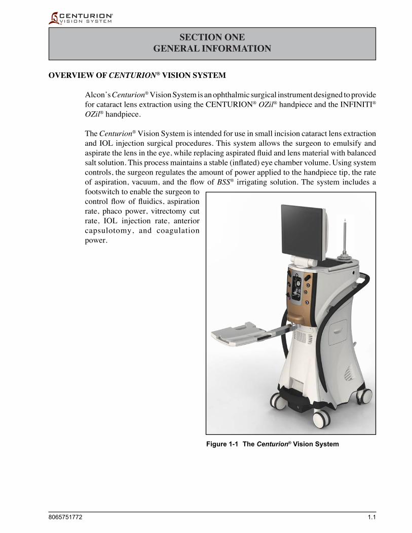
Alcon’s Centurion® Vision System is an ophthalmic surgical instrument designed to provide for cataract lens extraction using the CENTURION® OZil® handpiece and the INFINITI® OZil® handpiece.
The Centurion® Vision System is intended for use in small incision cataract lens extraction and IOL injection surgical procedures. This system allows the surgeon to emulsify and aspiratethelensintheeye,whilereplacingaspiratedfluidandlensmaterialwithbalancedsaltsolution.Thisprocessmaintainsastable(inflated)eyechambervolume.Usingsystemcontrols, the surgeon regulates the amount of power applied to the handpiece tip, the rate ofaspiration,vacuum,and theflowofBSS® irrigating solution. The system includes a footswitch to enable the surgeon to controlflowoffluidics, aspirationrate, phaco power, vitrectomy cut rate, IOL injection rate, anterior capsulotomy, and coagulation power.
Figure 1-1 The Centurion® Vision System

1.2 8065751772
Key Features of the Centurion® Vision System • Customizedcataractlensremovaloptions: - High performance CENTURION® OZil® handpiece with ultrasonic torsional
oscillations which can be used exclusively, combined, or alternated with traditional phaco. - High performance INFINITI® OZil® handpiece with ultrasonic torsional oscillations
which can be used exclusively, combined, or alternated with traditional phaco. • Advancedfluidicswithquick,smoothcontrolofaspiration. • AdvancedActive Fluidics™ technologywithquick,smoothcontrolofirrigationflow,
controlled via the front panel, footswitch, or remote control.. • AutomatedIVpolefortraditionalgravityfluidics,controlledviathefrontpanel,
footswitch, or remote control. • ProgrammableIOPtargetsetting. • Fullyprogrammable,multi-microprocessorcontrol. • ModularizedfluidicconnectionswithdisposableFluidicManagementSystem(FMS). • Emulationofventuri-likefluidicperformance. • PowerassistedIOLinsertionbywayoflightweight,autoclavableAutoSert® handpiece. • AbilitytodriveahighperformanceCENTURION® UltraVit® vitrectomy guillotine cutter. • Bipolarcoagulationcapability. • CapsulotomyusingtheINTREPID® capsulotomy device (ICD, future accessory). • Severaltraditionalmodalitiesofultrasonicpowercontrolincludingcontinuous,pulsed,
and burst application of ultrasonic power, as well as duty cycle management. • Wirelesslinearfootswitchcontrolofultrasonicpowerinphacosteps(sophisticated
control loop offers low-end control). • WirelesslinearfootswitchcontrolofaspirationflowrateinI/A,vit,andlensremoval
steps. • WirelesslinearfootswitchcontrolofvacuuminI/A,vit,andlensremovalsteps. • WirelesslinearfootswitchcontrolofIOLinsertion. • On-demandcontinuousirrigation. • Programmable,pressurizedrefluxviathefootswitch. • AbilitytosetIOP,vacuumlevels,andaspirationflowratestodesiredlevelsinphaco,
I/A, and vit steps. • Ability to switch between surgical steps using touch screen, remote control, or footswitch. • Emissionofvariabletonesforconfirmationofsystemoperationalstatus. • Voiceconfirmationduringsurgicalstepormodechanges. • Articulatingflatscreen:activematrixcolorLCDwithtouchscreen. • High-techgraphicaluserinterface. • Multi-channelIRremotecontrol.

8065751772 1.3
Indications For Use The Centurion®VisionSystemisindicatedforemulsification,separation,irrigation,and
aspiration of cataracts, residual cortical material and lens epithelial cells, vitreous aspiration and cutting associated with anterior vitrectomy, bipolar coagulation, and intra-ocular lens injection. The AutoSert®IOLInjectorHandpieceisintendedtodeliverqualifiedAcrySof® intraocular lenses into the eye following cataract removal.
The AutoSert® IOL Injector Handpiece achieves the functionality of injection of intraocular lenses. The AutoSert® IOL Injector Handpiece is indicated for use with AcrySof® lenses SN60WF, SN6AD1, SN6AT3 through SN6AT9, as well as approved AcrySof®lensesthatarespecificallyindicated for use with this inserter, as indicated in the approved labeling of those lenses.
The Centurion® Vision System, including accessories approved by Alcon, constitutes a complete surgical system and is intended exclusively for use by licensed ophthalmic surgeons and theirsurgicalteams.Thesesurgicalteamsareexperiencedatconductingphacoemulsificationproceduresinaproperlymaintainedsurgicalenvironment(qualifiedpersonnel,availabilityofbackup equipment) and are familiar with the operation of the equipment used as outlined in operator's manuals and directions for use (setup/checkout procedures to be completed before the surgical procedure; processing of reusable devices; maintenance; etc.).
Patient selection for use with the Centurion® Vision System (such as age, ophthalmic pathology, and other factors) is determined by the surgeon. The general patient age can range fromnewborntogeriatric,althoughtherehavebeenstudiesthathaveidentifiedthemeanageof patients that underwent cataract surgery was 72.32 yrs - men and 74.89 yrs - women.1
Intended Use Environments The Centurion® Vision System is intended for use in hospitals and ambulatory surgery centers.
Phaco Handpiece Note Throughout the rest of this manual the CENTURION® OZil® handpiece and the INFINITI®
OZil® handpiece will be referred to as phaco handpieces, unless one or the other must be referred to exclusively.
Trademark Note A button, mode, or step labeled OZil®, AutoSert®, or UltraChop refers to a display screen
control used with a phaco handpiece, INTREPID® AutoSert® IOL injector, or ALCON® UltraChopper® tip, respectively.
Abbreviation Descriptions Many of the abbreviations used in this manual and on the Centurion® Vision System are
describedinTable1-6.IconsareidentifiedinFigure1-2.
Accessory Equipment Accessoryequipmentconnectedtoorusedwiththisequipmentmustbecertifiedaccording
to the respective IEC Standard (e.g., IEC 60950-1 for data processing equipment, and IEC 60601-1formedicalequipment).Furthermore,allconfigurationsshallcomplywithclause16of IEC 60601-1:2005 (as amended). Anyone connecting additional equipment or otherwise
1. “Age and sex profile of patients having cataract surgery between 1986 and 2003”Philip O'Reilly, FRCSI (Ophth), U. Mahmound, FRCOphth, P. Hayes, FRCOphth, P. Tormey, FRCOphth, S. Beatty, MD.Journal of Cataract Refractive Surgery 2005; 31:2162-2166

1.4 8065751772
causingadifferentsystemconfigurationthanprovidedbyAlconisresponsibleforcontinuedcompliance to the requirements of clause 16 of IEC 60601-1:2005 (as amended). If in doubt, consult the Technical Services department or your local Alcon representative.
Follow local governing ordinances and recycling plans regarding disposal or recycling of device components and packaging.
User Information – Environmental Considerations The equipment that you have purchased requires the use of natural resources for its
production and operation. This equipment may also contain hazardous substances which could have potential effect on the environment and human health if disposed of improperly.
In order to avoid the entry of any such substances into our environment, and to promote natural resource conservation, please install, maintain, and operate the equipment in accordance with the instructions. Information on the location of hazardous substances, resource consumption and emissions of the equipment can be found throughout this Operator's Manual. Please use the appropriate take-back systems. Such take-back systems reuseorrecyclemanyofthematerialsinyourend-of-lifeequipmentinabeneficialway.PleasecontactyourlocalAlconofficeforassistanceintake-backoptionsthroughAlconor other providers.
The crossed-bin symbol located on this equipment reminds you to use take-back systems, while also emphasizing the requirement to collect waste equipment separately, and not dispose of it as unsorted municipal waste. The Pb notation, if present, indicates that the labeled device contains greater than 0.004% lead.
If you need more information on the collection, reuse or recycle systems available to you, please contact your local or regional waste administration, or contact your local Alconofficeformoreinformation.
Universal Precautions Universal precautions shall be observed by all people who come in contact with the
instrument and/or accessories to help prevent their exposure to blood-borne pathogens and/or other potentially infectious materials. In any circumstance, wherein the exact statusofbloodorbodyfluids/tissuesencounteredareunknown,itshallbeuniformlyconsidered potentially infectious and handled in accordance with OSHA or your own national guidelines.
EMC Statements It is important to install and use the equipment in accordance with the instructions in
order to prevent harmful interference with other devices in the vicinity. If this equipment causes harmful interference to other devices (determined by turning equipment off and on), the user is encouraged to try to correct interference by one or more of the following measures:
• Reorientorrelocatetheotherdevice(s). • Increasethedistancebetweentheequipment. • Connectthisequipmentintoanoutletonacircuitdifferentfromthattowhichthe
other device(s) is connected. • ConsultthemanufactureroryourAlconfieldserviceengineerforhelp.
Pb

8065751772 1.5
Table 1-1 Guidance and Manufacturer's Declaration - Electromagnetic Emissions - The Centurion® Vision System is intended for use in the electromagnetic environment specified below. The customer or the user of the Centurion® Vision System should assure that it is used in such an environment.
Emissions Test
RF emissionsCISPR 11
RF emissionsCISPR 11
Harmonic emissionsIEC 61000-3-2
Voltage fluctuations/Flicker emissionsIEC 61000-3-3
Electromagnetic Environment-Guidance
The Centurion® Vision System uses RF energy only for its internal function. Therefore, its RF emissions are very low and are not likely to cause any interference in nearby electronic equipment.
The Centurion® Vision System is suitable for use in all establishments other than domestic and those directly connected to a low voltage power supply network that supplies buildings used for domestic purposes.
The EMC Statement provides guidance on steps to take in case of electromagnetic interference.
Compliance
Group 1
Class A
Class A
Complies
Users should be aware of known RF sources, such as radio or TV stations and hand-held or mobile two-way radios, and consider them when installing a medical device or system.
Portable and mobile RF communications equipment such as cellular telephones can affect medical electrical equipment (see Table 1-3 for recommended separation distances).
Be aware that adding accessories or components, or modifying the medical device or system,maydegradetheEMIperformance.Consultwithqualifiedpersonnelregardingchangestothesystemconfiguration.
WARNINGS!
The use of accessories, transducers, and cables other than those specified, with the exception of transducers and cables sold by Alcon as replacement parts for internal components, may result in increased emissions or decreased immunity of the system.
The system should not be used adjacent to, or stacked with, other equipment; and that if adjacent to or stacked use is necessary, the system should be observed to verify normal operation in the configuration in which it will be used.
MAGNETIC AND ELECTRICAL INTERFERENCE - Magnetic and electrical fields are capable of interfering with the proper performance of the device. For this reason make sure that all external devices operated in the vicinity of the device comply with the relevant EMC requirements. X-ray equipment, magnetic resonance tomography (MRT), nuclear magnetic resonance (NMR), or magnetic resonance imaging (MRI) devices are possible sources of interference as they may emit higher levels of electromagnetic radiation. See the Magnetic Resonance Unsafe icon in Figure 1-2.

1.6 8065751772
Table 1-2 Guidance and Manufacturer's Declaration - Electromagnetic Immunity - The Centurion® Vision System is intended for use in the electromagnetic environment specified below. The customer or the user of the Centurion® Vision System should assure that it is used in such an environment.
Note: UT is the a.c. mains voltage prior to application of the test level.Note 1: At 80 MHz and 800 MHz, the higher frequency range applies.Note 2: These guidelines may not apply in all situations. Electromagnetic propagation is affected by absorption and reflection from
structures, objects, and people.a Field strengths from fixed transmitters, such as base stations for radio (cellular/cordless) and land mobile radios, amateur radio, AM and
FM radio broadcast, and TV broadcast cannot be predicted theoretically with accuracy. To access the electromagnetic environment due to fixed RF transmitters, an electromagnetic site survey should be considered. If the measured field strength in the location in which the (equipment or system) is used exceeds the applicable RF compliance level above, the (equipment or system) should be observed to verify normal operation. If abnormal performance is observed, additional measures may be necessary, such as re-orienting or relocating the Centurion® Vision System.
b Over the frequency range 150 kHz to 80 MHz, field strengths should be less than 3 V/m.
Immunity Test
Electrostatic discharge (ESD)IEC 61000-4-2
Electrical fasttransient/burstIEC 61000-4-4
SurgeIEC 61000-4-5
Voltage dips, short interruptions, and voltage variations on power supply input linesIEC 61000-4-11
Power frequency (50/60 Hz) magnetic fieldIEC 61000-4-8
Conducted RFIEC 61000-4-6
Radiated RFIEC 61000-4-3
IEC 60601 Test Level
• ±6 kV contact• ±8 kV air
• ±2 kV for power supply lines
• ±1 kV for input/output lines
• ±1 kV differential mode• ±2 kV common mode
• < 5 % UT (> 95 % dip in UT) for 0.5 cycle
• 40 % UT (60 % dip in UT) for 5 cycles
• 70 % UT (30 % dip in UT) for 25 cycles
• < 5 % UT (> 95 % dip in UT) for 5 s
3 A/m
3 Vrms150 kHz to 80 MHz
3 V/m80 MHz to 2.5 GHz
Compliance Level
• ±6 kV contact• ±8 kV air
• ±2 kV for power supply lines
• ±1 kV for input/output lines
• ±1 kV differential mode• ±2 kV common mode
• < 5 % UT (> 95 % dip in UT) for 0.5 cycle
• 40 % UT (60 % dip in UT) for 5 cycles
• 70 % UT (30 % dip in UT) for 25 cycles
• < 5 % UT (> 95 % dip in UT) for 5 s
3 A/m
3 Vrms
3 V/m
Electromagnetic Environment-Guidance
Floors should be wood, concrete, or ceramic tile. If floors are covered with synthetic material, the relative humidity should be at least 30 %.
Mains power quality should be that of a typical hospital (including ambulatory surgery center) environment. To avoid pre-mature shutdown due to fast transients avoid powering the Centurion® Vision System on the same branch circuit with sources that can generate fast transients (inductive switching; e.g., high current motors).
Mains power quality should be that of a typical hospital (including ambulatory surgery center) environment.
Mains power quality should be that of a typical hospital (including ambulatory surgery center) environment. If the use of the Centurion® Vision System requires continued operation during power mains interruptions, it is recommended that the Centurion® Vision System be powered from an uninterruptible power supply with a minimum rating of 1200VA.
Power frequency magnetic fields should be at levels characteristic of a typical location in a typical hospital (including ambulatory surgery center) environment.
Portable and mobile RF communications equipment should be used no closer to any part of the Centurion® Vision System, including cables, than the recommended separation distance calculated from the equation applicable to the frequency to the transmitter.
Recommended separation distance:
d = 1.2√P
d = 1.2 √ P 80 MHz to 800 MHz
d = 2.3 √ P 800 MHz to 2.5 GHz
where P is the maximum output power rating to the transmitter in watts (W) according to the transmitter manufacturer and d is the recommended separation distance in meters (m).
Field strength from fixed RF transmitters, as determined by an electromagnetic site surveya, should be less than the compliance level in each frequency rangeb.
Interference may occur in the vicinity ofequipment marked with following symbol.
8065751772 1.7
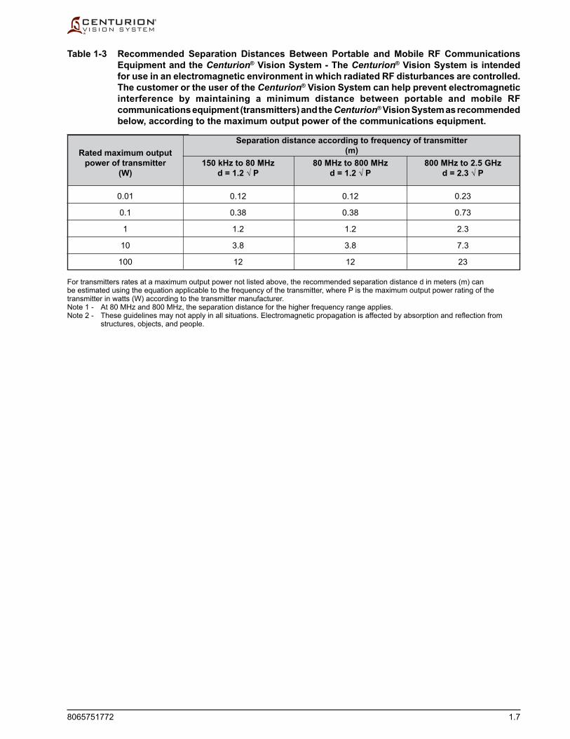
Table 1-3 Recommended Separation Distances Between Portable and Mobile RF Communications Equipment and the Centurion® Vision System - The Centurion® Vision System is intended for use in an electromagnetic environment in which radiated RF disturbances are controlled. The customer or the user of the Centurion® Vision System can help prevent electromagnetic interference by maintaining a minimum distance between portable and mobile RF communications equipment (transmitters) and the Centurion® Vision System as recommended below, according to the maximum output power of the communications equipment.
For transmitters rates at a maximum output power not listed above, the recommended separation distance d in meters (m) can be estimated using the equation applicable to the frequency of the transmitter, where P is the maximum output power rating of the transmitter in watts (W) according to the transmitter manufacturer.Note 1 - At 80 MHz and 800 MHz, the separation distance for the higher frequency range applies.Note 2 - These guidelines may not apply in all situations. Electromagnetic propagation is affected by absorption and reflection from
structures, objects, and people.
800 MHz to 2.5 GHzd = 2.3 √ P
0.23
0.73
2.3
7.3
23
80 MHz to 800 MHzd = 1.2 √ P
0.12
0.38
1.2
3.8
12
150 kHz to 80 MHzd = 1.2 √ P
0.12
0.38
1.2
3.8
12
Rated maximum outputpower of transmitter
(W)
0.01
0.1
1
10
100
Separation distance according to frequency of transmitter(m)

1.8 8065751772
Equipment Contains Radio Transmitters
The Centurion® Vision System is a medical device designed for Indoor Use Only, that incorporates short-range frequency radio transmitters for use solely by the Centurion® system for communication with system components. These short-range frequency radio transmitters meet the EU and AFTA countries requirements. They are also FCC; IC; R&TTE 1999/5/EC and Japanese Radio Law compliant.
• ZigBeeRadioModular(CommunicationlinkwithFootswitch,SGSandMediaCenter) - Frequency or frequency band of transmission: 2.405 – 2.480 GHz - Type and frequency characteristics of the modulation: OQPSK (Offset quadrature
phase-shift keying) - The Effective Radiated Power (ERP): 12.91 dBm (19.54 mW)
• WirelessLANdevice(Optional) - Frequency or frequency band of transmission: 2.412 – 2.484 GHz and 5.180 - 5.700 GHz - Type and frequency characteristics of the modulation: OFDM, DSSS, CCK, DQPSK,
DBPSK, 64 QAM, 16 QAM - The Effective Radiated Power (ERP): 17.09 dBm (51.17 mW)
• WirelessFootswitchCharger - Frequency or frequency band of charging transmission: 50 kHz - Frequency or frequency band communication transmission: 115 kHz - Type and frequency characteristics of the modulation: FSK (Frequency Shift Keying) - TheEffectiveRadiatedPower(ERP):-14.89dBm(53.18μW)
USA – Federal Communications Commission (FCC)
This device complies with part 15 of the FCC Rules. Operation is subject to the following two conditions: (1) This device may not cause harmful interference, and (2) this device must accept any interference received, including interference that may cause undesired operation.
CAUTIONChange or modifications made to this equipment (including antenna) not expressly approved by Alcon may void the FCC authorization to operate this equipment.
FCC Radiation Exposure Statement
CAUTIONTo ensure that the radio transmitter complies with current FCC regulations limiting both maximum output RF power and human exposure to radio frequency radiation, a separate distance of at least 20 cm must be maintained between the unit’s antenna and the body of the user and any nearby persons at all times, and unit’s antenna must not be co-located or operating in conjunction with any other antenna or transmitter.

8065751772 1.9
Canada – Industry of Canada (IC) This device complies with Industry Canada licence-exempt RSS standards. Operation
is subject to the following two conditions: (1) This device may not cause harmful interference, and (2) this device must accept any interference, including interference that may cause undesired operation of the device.
Cet appareil est conforme aux normes d’Industrie Canada RSS exemptes de licence. Son fonctionnement est soumis aux deux conditions suivantes: (1) Cet appareil ne doit pas provoquer d’interférences nuisibles, et (2) cet appareil doit accepter toute interférence, y compris les interférences pouvant provoquer un fonctionnement indésirable de l’appareil.
Transmitter Antenna: Under Industry Canada regulations, this radio transmitter may only operate using an
antenna of a type and maximum (or lesser) gain approved for the transmitter by Industry Canada. To reduce potential radio interference to other users, the antenna type and its gain should be so chosen that the equivalent isotropically radiated power (e.i.r.p.) is not more than that necessary for successful communication.
Conformément à la réglementation de l’industrie du Canada, cet émetteur de radio ne peut être utilisé qu’avec un type d’antenne approuvé pour l’émetteur par Industrie Canada et seulement avec une valeur de gain inferieur ou égale au gain maximum approuvé par Industrie Canada. Pour réduire les risques potentiels d’interférence à autrui, le type d’antenne et son gain doivent être choisis de sorte que la puissance isotrope rayonnée équivalente (p.i.r.e.) ne dépasse pas la valeur qui est nécessaire pour une communication réussi.
Exposure of Humans to RF Fields: This device complies with the RF exposure limits for humans as called out in RSS-102.
Cet appareil est conforme aux limites d’exposition RF pour les êtres humains comme elles le sont notifiées dans la norme RSS-102.

1.10 8065751772
Table 1-4 Information on the Location of Hazardous Substances in the Centurion® Vision System - The Centurion® Vision System contains hazardous substances which could have potential effect on the environment and human health if disposed of improperly.
Material Location Hazardous Substances Contained
Printed Circuit Board Assembly Lead, Polybrominated Biphenyls (PBB)
Other Electrical / Electronic Device Lead, Polybrominated Biphenyls (PBB)
Cable Assembly Lead
Power Supply Lead, Polybrominated Biphenyls (PBB)
Host PC Module Lead, Polybrominated Biphenyls (PBB)
Liquid Crystal Display Lead
Battery Lead, Lithium, Zn/MnO2
IV Pole Assembly Lead, Polybrominated Biphenyls (PBB)
Remote Control Lead
Fluidics Assembly Lead
Pneumatic Assembly Lead
Europe – R&TTE Directive 99/5/EC
This device complies with the requirements of the Council Directive 99/5/EC (R&TTE).
CAUTION The radio equipment is intended to be used in all EU and AFTA countries. Outdoor
use may be restricted to certain frequencies and/or may require a license for operation. Contact local Authority for procedure to follow.
PRECAUTION: Combinations of power levels and antennas resulting in a radiated power of above 100 mW equivalent isotropic radiated power (e.i.r.p) are considered as not compliant with the above mentioned directive and are not allowed for use within the European community and countries that have adopted the European R&TTE directive 1999/5/EC.
For more details on legal combinations of power levels and antennas, contact Alcon Compliance.
Japan
This device complies with Japanese Radio Law.

8065751772 1.11
WARNINGS AND CAUTIONS
Many of these warnings are stated elsewhere in this manual; however, for easy reference they are repeated in greater detail here. If additional information is required, please contact your local Alcon service representative, or the Technical Services Department.
There are no user serviceable components inside the Centurion® Vision System console or footswitch. Refer all service issues to your factory-trained Alcon service engineer.
WARNINGS!
To avoid risk of electric shock, this equipment must only be connected to a supply mains with protective earth (ground).
The Centurion® Vision System battery can only be serviced by a factory-trained Alcon service engineer. Access by untrained personnel can lead to injury.
A qualified technician must perform a visual inspection of the following components every twelve months: • Warning Labels (see Figure 1-3) • Power Cord • FusesIn case of a deficiency, do not use the system; call Alcon Technical Services.
A qualified technician must check ground continuity and leakage current every twelve months to ensure they are within the limits of the applicable standards (for example: EN60601-1/IEC60601-1). Values must be recorded, and if they are above the limits of the applicable standards, or 50 % above initial measurement, do not use the system; call Alcon Technical Services.
If the Centurion® Vision System is used at the 220 V - 240 V range in the United States or Canada, it should be used on a center-tapped, 240 V single phase circuit.
Console isolation from mains is achieved through a two pole power switch. Turn OFF power switch or unplug the power cord from wall outlet to achieve isolation from mains.
Do not use the Centurion® Vision System near flammable anesthetics.
Do not exceed maximum capacity of drain bag (500 ml). Excessive pressure can result from exceeding drain bag maximum capacity and potentially result in a hazardous condition for the patient.
Inadvertent actuation of Prime or Tune while a handpiece is in the eye can create a hazardous condition that may result in patient injury.
Keep clear of display base when raising display from stored position to prevent skin, hair, and /or clothing from being trapped at the base.
The maximum allowable load on the instrument tray is 20 lb. (9 kg).
Place the instrument tray in the stored position prior to transportation to avoid a situation that could cause the system to tip.
Console might overbalance when it is pushed and its wheels are immobilized (blocked).
Route the footswitch cable, power cord and any other cables connected to the Centurion® Vision System to avoid tripping.

1.12 8065751772
WARNINGS!
Appropriate use of Centurion® Vision System parameters and accessories is important for successful procedures. Use of low vacuum limits, low flow rates, low bottle heights, high power settings, extended power usage, power usage during occlusion conditions (beeping tones), failure to sufficiently aspirate viscoelastic prior to using power, excessively tight incisions, and combinations of the above actions may result in significant temperature increases at incision site and inside the eye, and lead to severe thermal eye tissue damage.
Good clinical practice dictates testing for adequate irrigation, aspiration flow, reflux, and operation as applicable for each handpiece prior to entering eye.
Ensure that the tubings are not occluded during any phase of operation.
If the handpiece test chamber is collapsed after tuning, there is a potential of low irrigation flow through the handpiece and may result in a fluidic imbalance. This, in turn, may cause a shallowing or collapsing of the anterior chamber.
Avoid setting the patient above the FMS unless PEL is used. Operating with the patient above the FMS without PEL adjustment will result in a lower irrigation pressure than indicated on the display, and possible underventing.
Use of BSS® irrigating fluid bags other than those approved by Alcon for use in the Active Fluidics™ system can result in patient injury or system damage.
Use of appropriate technique and settings is important to minimize fragments and turbulence.
Do not remove the FMS during the surgical procedure.
In the event of a system error release footswitch to the up position.
Improper handling or removal of dual irrigation handpiece tip from eye may cause draining of the fluidics system.
CAUTIONS
• Modification of the equipment is NOT allowed without prior authorization from the manufacturer. If this equipment is modified, appropriate inspection and testing must be conducted to ensure continued safe use of the equipment.
• Avoid spilling BSS® irrigating solution, or moisture of any kind, around the electrical handpiece connectors.
• Do not spray any liquid (i.e. cleaning solution or water) upward into the console vents.
• Do not push or pull the unit by the display, the instrument tray, or the IV pole. Wrapping around the rear and sides of the system is a handle provided for moving the instrument. The unit should be pulled and not pushed, especially over elevator and door thresholds.

8065751772 1.13
Phaco Handpiece Care
Phaco handpieces are surgical instruments and must be handled with care. The handpiece tip should not touch any solid object while in operation. Immediately following surgery the handpiece must be thoroughly cleaned. Be sure handpiece connector is completely dry before connecting it to console. For cleaning and sterilization procedures, see the Directions for Use (DFU) supplied with the handpiece.
WARNINGS!
If in the medical opinion of the physician a patient with a prion related disease undergoes a high risk procedure, the instrument should be destroyed or be processed according to local requirements.
Use of a phaco handpiece in the absence of irrigation flow and/or in the presence of reduced or lost aspiration flow and/or sideways orientation of the Kelman® and OZil® 12 tips can cause excessive heating and potential thermal injury to adjacent eye tissues.
Appropriate use of Centurion® Vision System parameters and accessories is important for successful procedures. Use of low vacuum limits, low flow rates, low bottle heights, high power settings, extended power usage, power usage during occlusion conditions (beeping tones), failure to sufficiently aspirate viscoelastic prior to using power, excessively tight incisions, and combinations of the above actions may result in significant temperature increases at incision site and inside the eye, and lead to severe thermal eye tissue damage.
Use of an ultrasonic handpiece other than an OZil® torsional handpiece, or use of a handpiece repaired without Alcon authorization, is not permitted, and may result in patient injury, including potential shock hazard to patient and/or operator.
The U/S tips supplied in the Centurion® Vision System pack are only to be used on an OZil® torsional handpiece. Each U/S tip is intended to be used only once per case, and then disposed of according to local governing ordinances.
Mismatching U/S tips and infusion sleeves may create potentially hazardous fluidic imbalances.
Directing energy toward non-lens material, such as iris or capsule, may cause mechanical and/or thermal tissue damage.
Perform visual inspection of accessories for burs or bent tips prior to use.
Use of appropriate technique and settings is important to minimize fragments and turbulence.

1.14 8065751772
CAUTIONS
Never ultrasonically clean the phaco handpiece; irreparable damage may result.
Prior to sterilization, the phaco handpiece should always have the connector end cap secured and placed in the sterilization tray. This will prevent damage to the connectors and handpieces during handling, and especially during autoclaving.
The phaco handpiece and INTREPID® AutoSert® IOL Injector must be at room temperature just before use. Allow the handpiece to air cool for at least 15 minutes after autoclaving; never immerse the handpiece in liquid when hot.
Do not operate the phaco handpiece unless the tip is immersed in BSS® sterile irrigating solution or distilled water or is in surgical use. Irreparable damage to the handpiece and tip can result if run dry.
Ensure that test chamber is filled with BSS® sterile irrigating solution before tuning the phaco handpiece. Tuning a handpiece dry may result in premature tip failure and breakage.
Quenching a hot handpiece in water can cause damage and will void warranty.
Be sure handpiece is completely dry before connecting it to console. Damage to handpiece and console may result if plugged in when wet.
Phaco Handpiece Tips
Ensure that handpiece tip is fully tightened to the handpiece. If not securely attached, an error may be generated and/or inadequate tuning will occur. Ensure that the tip is not too tight so that it can be removed after use.
Use of a tool other than tip wrenches supplied by Alcon may cause damage to the tip and/or handpiece.
WARNING!Poor clinical performance will result if tip is not secured tightly to the handpiece.
During any ultrasonic procedure, metal particles may result from inadvertent touching of the ultrasonic tip with a second instrument. Another potential source of metal particles resulting from any ultrasonic handpiece may be the result of ultrasonic energy causing micro abrasion of the ultrasonic tip.

8065751772 1.15
Ultraflow™* II I/A Handpiece
Prior to each procedure inspect the two O-rings where the tip screws onto the Ultraflow™* II I/A handpiece. If damaged or missing, replace the o-rings. If in doubt, contact Alcon's Technical Services Department.
WARNINGS!Use of non-Alcon surgical reusable or disposable I/A handpieces that do not meet Alcon surgical specifications, or use of an Alcon handpiece not specified for use with the Centurion® Vision System, may result in a fluidic imbalance. This, in turn, may cause a shallowing or collapsing of the anterior chamber.
Exceeding the recommended level of 100 mmHg (133 hPa) with a 0.5 mm or larger I/A tip may cause anterior chamber shallowing and/or incarceration or tearing of posterior capsule.
I/A tips are not to be used with a phaco handpiece.
Recommended Vacuum Range for I/A Tips
It is important that only the proper size I/A tip be used when operating with maximum vacuum. Only 0.2 mm or 0.3 mm I/A tips should be used with vacuum limits above 100 mmHg (133 hPa). I/A adjustable vacuum range is 0 - 700 mmHg (0 - 933 hPa).
Centurion® Vitrectomy Probe
The vitrectomy probe, a guillotine vitreous cutter, is intended for single use only.
Vitrectomy cutting performance may vary at high altitudes. Consult Alcon Technical Service for additional information.
WARNINGS!Do not test or operate vitrectomy probe unless tip of probe is immersed in BSS® sterile irrigating solution or distilled water or is in surgical use. Irreparable damage to the probe and tip can result if run dry.
Perform visual inspection of accessories for burs or bent tips prior to use.
Connect pneumatic tubing connectors from vitrectomy probe to console prior to initiating prime of probe. Initiating prime of the vitrectomy probe, or running the vitrectomy system, with one or both pneumatic connectors disconnected may cause the flow of non-sterile air over the sterile field for a brief moment.
Do not use vitrectomy probes that are not approved for use on Centurion® system.
After filling and testing, and before surgical use, verify that the probe is properly actuating and aspirating. This may require lowering cut rate to achieve good visualization. The port should always remain in open position in footpedal position 1. If cutting port is partially closed while in position 1, replace the probe. Prior to entry into the eye, and with tip of probe in sterile irrigating solution, the surgeon should step on the footpedal for visual verification that the probe is cutting:• If the cutter is observed to not fully close, or does not move when the probe
is actuated, replace the probe.• If cutting port is partially closed while idle, replace the probe.• If air bubbles are observed in the aspiration line or exiting the probe tip during
priming, replace the probe.• If a reduction of cutting capability or vacuum is observed during the surgical
procedure, stop immediately and replace the probe.

1.16 8065751772
INTREPID® AutoSert® IOL Injector
CAUTIONS•Do not ultrasonically clean the AutoSert® IOL Injector connector. Ultrasonic
cleaning will cause irreparable damage.•UsecarewhenhandlingAutoSert® IOL Injector, particularly when cleaning. Always
clean handpiece over a surface cushioned with a pad or rubber mat.• Besurehandpiececableconnectorisdrybeforeconnectingittotheconsole.•DonotdisconnectcableconnectorfromCenturion® system console until the IOL
Injector plunger is fully retracted.•Donot immerse theAutoSert® IOLInjector inanyfluidwhentheplunger isnot
retracted.•As part of a properlymaintained surgical environment, it is recommended that
a backup IOL injector be made available in the event the AutoSert® IOL injector handpiece does not perform as expected.
WARNINGS!• The INTREPID® AutoSert® IOL Injector is non-sterile and must be cleaned and
sterilized prior to, and immediately after, each use.• Never immerse the IOL injector in liquid after autoclaving; allow it to air cool for at
least 15 minutes. Quenching could result in a potentially hazardous condition for the patient.
• The AutoSert® IOL Injector delivery system is for the implantation of Alcon qualified AcrySof® foldable IOLs. Unqualified lenses shall not be used with the system. See INTREPID® AutoSert® IOL Injector DFU or AcrySof® IOL DFU, or contact your Alcon representative, for qualified lens/cartridge combinations.
• The cartridge/IOL combination listed in the DFU, along with Alcon settings, has been validated per section 5 of BS EN ISO 11979-3:2006. Appropriate use of injector handpiece settings is important for successful IOL implantation. Inappropriate use of settings may lead to a potentially hazardous condition for the patient.
• Fully retract plunger before detaching nosecone from AutoSert® IOL Injector; otherwise, this could expose non-sterile portion of shaft and result in a potentially hazardous condition for the patient.
• For the intended IOL to be implanted, the proper Cartridge profile must be selected from the driving console, and the proper plunger must be attached to the AutoSert® IOL Injector. Failure to do so can result in a potentially hazardous condition for patient.
• The metal reusable plunger must be sterilized after each use. The reusable plunger is to be installed onto the handpiece or into the wrench prior to sterilization.
Aspiration/Vacuum Adjustments
Adjusting aspiration rates or vacuum limits above the preset values may result in aspirationlevels(volumes)exceedingirrigationinflow.
WARNING!Adjusting aspiration rates or vacuum limits above the preset values, or lowering the IOP or IV pole below the preset values, may cause chamber shallowing or collapse which may result in patient injury.
8065751772 1.17
Presurgical Check-out Tests
Presurgical check-out tests must be performed as outlined in Section Three of this manual (Operating Instructions). If an Event message is displayed on the front panel, refer to the Troubleshooting section of this manual. If the problem persists, DO NOT PROCEED.
WARNINGS!When filling handpiece test chamber, if stream of fluid is weak or absent, good fluidics response will be jeopardized. Good clinical practice dictates the testing for adequate irrigation and aspiration flow prior to entering the eye.
Ensure that tubings are not occluded or pinched during any phase of operation.
Perform visual inspection of accessories for burrs or bent tips prior to use.
IV Pole
WARNINGS!
Keep clear of the IV pole when it is in motion to prevent skin, hair, and/or clothing from being trapped in the IV pole mechanism. The IV pole moves during power on/off, priming, and bottle height adjustment.
IV pole rises automatically. To avoid stretching drip chamber tubing, and possibly pulling drip chamber out of bottle, tubing must hang freely with no interference.
When out of use, remove fluid bottle from IV pole and flip bottle hanger into its storage position to avoid injury.
Empirical numbers for bottle heights are not a replacement for competent surgical technique. The surgeon should visually and physically monitor intraocular pressure.
Footswitch
If required, the footswitch may be wiped with alcohol, mild soap and water, or any germicidal solution that is compatible with the plastic parts.
WARNING!Route the footswitch cable properly to avoid tripping.
CAUTIONSDo not clean the footswitch using solvents, abrasives, or any cleaner that is not compatible with plastic parts made of LEXAN EXL9112. Damage may result.
Never pick up or move the footswitch by the cable. Dropping or kicking the footswitch can cause irreparable damage.

1.18 8065751772
Occlusion Tones
Two different occlusion tones (intermittent beeping tones during occlusion) indicate thatthevacuumisnearoratitspresetlimit,andaspirationflowisreducedorstoppedtoavoidexceedingthelimit.Thefirsttype,theI/Aocclusiontone,soundswhenocclusion occurs during aspiration only (in the absence of ultrasonic power). The I/A occlusion tone is a lower, intermittent single beep. The second type of occlusion tone, the phaco occlusion tone, is a higher, intermittent double beep, and sounds when occlusion occurs during application of ultrasonic power.
The I/A occlusion and phaco occlusion tones indicate that the vacuum has reached its maximum allowed preset value. The I/A occlusion tone can be turned off, while the phaco occlusion tone cannot be turned off.
WARNINGS!The phaco occlusion bell indicates no aspiration flow. Use of high phaco settings and/or prolonged use may lead to thermal injury.
Use of the phaco handpiece in the absence of irrigation flow and/or in the presence of reduced or lost aspiration flow can cause excessive heating and potential thermal injury to adjacent eye tissues.
In the event of a persistent loss of aspiration during the application of phaco power, remove phaco power via footswitch control.
Vacuum Tone
A vacuum tone is provided. The pitch will vary relative to the amount of vacuum. A highvacuumcanindicatethatlittletonoflowisoccuring.Thistonecanbereducedin volume, but not turned off.
WARNINGS!A moderate to high vacuum tone may indicate little to no flow is occuring. Use of the phaco handpiece in the absence of irrigation flow and/or in the presence of reduced or lost aspiration flow can cause excessive heating and potential thermal injury to adjacent eye tissues.
Do not exceed maximum capacity of drain bag (500 ml). Excessive pressure in drain bag can result from exceeding its maximum capacity and potentially result in a hazardous condition for the patient.
In the event of a persistent loss of aspiration during the application of phaco power, remove phaco power via footswitch control.
Cautery, Diathermy, Coagulation Definition
The Centurion® Vision System uses the word “Coagulation” in place of Cautery or Diathermy,basedonthefollowingdefinition:
Coagulation - Isolated, bipolar, high frequency current supplied to conductors (e.g. forceps). Current passes between these electrodes, halting bleeding. (Abbreviated “Coag” in some of the text of this operator’s manual.)
8065751772 1.19
Coagulation Function
Listed below are general precautions to be followed when using the Coagulation function:
• Toensuresafeoperationofthecoagulationfunction,onlyapprovedcablesand accessories must be used (See your Alcon representative). Coagulation performance can be guaranteed only when using Alcon components or Alcon-endorsed components.
• Toreducetheriskofaccidentalburns,cautionshouldalwaysbetakenwhenoperating high-frequency surgical equipment.
• Interferenceproducedbytheoperationofhigh-frequencysurgicalequipmentmayadverselyinfluencetheoperationofotherelectronicequipment.
• Accessoriesshouldbecheckedregularly;electrodecablesshouldparticularlybechecked for possible damage to the insulation.
• Operationofthecoagulationstepislimitedtoextraocularusesonly. • Thelowestpowerlevelincoagulationstepshouldalwaysbeselectedforthe
intended purpose. • Skin-to-skincontact(forexamplebetweenthearmsandbodyofthepatient)
should be avoided, for example by insertion of dry gauze. • WhenHF(highfrequency)surgicalequipmentandphysiologicalmonitoring
equipment are used simultaneously on the same patient, any monitoring electrodes should be placed as far as possible from the surgical electrodes. Needle monitoring electrodes are not recommended.
• Inallcases,monitoringsystemsincorporatinghighfrequencycurrent-limitingdevices are recommended.
• Thecablestothesurgicalelectrodesshouldbepositionedinsuchawaythatcontact with the patient or other leads is avoided.
• Temporarilyunusedactiveelectrodesshouldbestoredsothattheyareisolatedfrom the patient.
• Theuseofflammableanaestheticsoroxidizinggasessuchasnitrousoxide(N2O) and oxygen should be avoided if a surgical procedure is carried out in the region of the thorax or the head, unless these agents are sucked away.
• Non-flammableagentsshouldbeusedforcleaninganddisinfectionwhereverpossible. • Flammableagentsusedforcleaningordisinfecting,orassolventsofadhesives,
should be allowed to evaporate before the application of HF surgery. Some materials, for example cotton, wool and gauze, when saturated with oxygen may be ignited by sparks produced in normal use of the HF surgical equipment.
• Accessoriesshouldhavearatedvoltageequaltoorgreaterthanthemaximumcoagulation output voltage.
WARNINGS!Do not use the coagulation function on patients with pacemakers or implanted defibrillatory devices. If electrosurgery is used on patients with implanted cardiac pacemakers or defibrillatory devices or pacemaker electrodes, be aware that irreparable damage to the pacemaker or defibrillatory device and its function may occur and lead to ventricular fibrillation. Please check with the pacemaker or defibrillatory device manufacturers for their recommendations.
Failure of the HF surgical equipment (coagulation circuitry) could result in an unintended increase of output power.
1.20 8065751772
VideOverlay System
WARNINGS!Do not remove VideOverlay cover; there are no user-serviceable parts inside. Refer servicing to qualified service personnel.
Do not simultaneously touch the VideOverlay enclosure and the patient.
CAUTIONS•Do not use multiple portable socket outlets with this system.• Use only the Alcon-supplied serial cable to connect the Centurion® Vision
System to the VideOverlay System.

8065751772 1.21
Consumable Packs
Consumable items used with the Centurion® Vision System during surgery are designed to be used once and then discarded, unless labeled otherwise.
All Centurion® packs contain Directions for Use (DFU). It is important to read and understand the DFU’s prior to use.
In all cases, the instrument setup instructions contained in the manual should be thoroughlyunderstoodpriortousinganyofthepackconfigurations.
PRECAUTION: If an inconsistency exists between the instructions in the operator’s manual and the Directions For Use (DFU) supplied with a consumable pack or accessory, follow the DFU.
WARNINGS!
Mismatch of consumable components and use of settings not specially adjusted for a particular combination of consumable components may create a patient hazard.
Do not use packs that have exceeded the expiration date.
Sterile disposable medical devices should not be reused! These components have been designed for one time use only; do not reuse.
Potential risk from reuse or reprocessing the following products labeled for single use include:• Bipolar Coagulation Instruments - Thermal injury or electrical shock caused by a
damaged bipolar instrument, and foreign particle introduction into the eye.• Fluid Management Components - Fluid path leaks or obstruction resulting in reduced
fluidics performance, and foreign particle introduction into the eye.• Phacoemulsification Tips - Reduced tip cutting performance, presence of tip burrs,
fluid path obstruction, and foreign particle introduction into the eye.• Vitreous Cutting Instruments - Reduced vitreous cutting performance, fluid path
obstruction, and foreign particle introduction into the eye.
The equipment used in conjunction with the Alcon disposables constitutes a complete surgical system. Use of disposables other than Alcon disposables may affect system performance and create potential hazards, and if it is determined to have contributed to the malfunction of the equipment under contract, could result in the voidance of the contract and/or invoicing at prevailing hourly rates.
Perform visual inspection of accessories for burs or bent tips prior to use.
Do not remove the FMS during the procedure.
Do not use any Vitrectomy probes that have not been approved for use on the Centurion® Vision System.

1.22 8065751772
PRODUCT SERVICE
For product service, please contact Alcon’s Technical Services Department at the number provided below.
Operators experiencing problems with the system should refer to the Operating Instructions and Troubleshooting sections of this manual. A problem which persists should be referred to the Alcon Technical Services Department or your local authorized service representative.
For optimum performance, it is the user’s responsibility to schedule preventive maintenance service on the system and its accessories a minimum of one time per year. Additional preventive maintenance may be required based upon system use. Alcon’s Field Service Engineers are trained and equipped to provide the highest quality of workmanship.
Safetyperformanceshouldbeverifiedbytheuser(e.g.,qualifiedservicepersonnel)atleast twice a year. Ground resistance, leakage current, and dielectric withstand voltage must be checked to appropriate national standard.
To avoid unnecessary shipping, please contact your Alcon Technical Services Department prior to return of any system or accessories. If return of the equipment is deemed necessary, a Return Material Authorization will be issued with appropriate shipping instructions.
Alcon Technical Services Department15800 Alton Parkway
Irvine, California 92618-3818(800) 832-7827, or (949) 753-1393
8065751772 1.23
LIMITED WARRANTY
Alcon will repair or replace at its option, any system or accompanying accessories found to be defective in material and/or workmanship for a period of one (1) year from the date of initial installation. This warranty applies to the original purchaser of the system, when said system is properly installed, maintained, and operated in accordance with published instructions.
Alcon shall not be obligated to provide services under this warranty for damage to or destruction of systems covered where such damage or destruction is a result of orcausedbyfireorexplosionofanyorigin,riot,civilcommotion,aircraft,war,oranyActofGodincluding,butnotlimitedtolightning,windstorm,hail,floodoranearthquake.
This warranty does not cover damage resulting from service repair or other alteration by any person other than an Alcon-authorized service person, and any warranties provided by Alcon with respect to this equipment shall become void and of no further force and effect if this equipment is serviced by anyone other than Alcon-authorized service personnel. In particular, Alcon shall have no obligation to replace, repair or credit customer’s account for the cost of the equipment, which has been subject to service or other alteration by persons other than Alcon-authorized service personnel.
The express warranty above is the sole warranty obligation of Alcon, and the remedy provided above is in lieu of any and all other remedies. There are no other agreements, guarantees, or warranties – oral or written, expressed or implied – including,withoutlimitation,warrantiesofmerchantabilityorfitnessforaparticularpurpose. Alcon shall have no liability whatsoever for any incidental or consequential damages arising out of any defect, improper use, or unauthorized service or repair.
WARNING!The consumable products used in conjunction with ALCON® instrument products constitute a complete surgical system. Use of consumable products and handpieces other than those manufactured by Alcon may affect system performance and create potential hazards. If it is determined that consumable products or handpieces not manufactured by Alcon have contributed to the malfunction of the equipment during warranty period, service will be provided at prevailing hourly rates.

1.24 8065751772
Table 1-5 SPECIFICATIONS - This table is a quick reference point to identify basic system specifications, system requirements, and performance figures.
ABS Aspiration Bypass SystemAFR Aspiration Flow Rate Asp Aspiration BF Body Floating BSS Balanced Salt Solution cc/min Cubic centimeters per minute Coag Coagulation CPM Cuts Per Minute DFU Directions For Use ESD Electro Static Discharge FMS Fluidic Management System FTSW Footswitch HF High Frequency
Table 1-6 ABBREVIATIONS USED WITH THE CENTURION® VISION SYSTEM
Abbrev. Description Abbrev. Description Abbrev. Description UL Underwriters Laboratories U/S Ultrasound USB Universal Serial Bus V Volt Vac Vacuum Vit Vitrectomy IEC International Electrotechnical
Commission IPN1N2 International Protection Code N1 - solid objects (0 to 6, or X - not
required to be specified) N2 - ingress of water (0 to 8, or X - not
required to be specified)
HP Handpiece I/A Irrigation/Aspiration IOL Intraocular Lens IOP Intraocular Pressure IR Infra Red Irr Irrigation IVO Infiniti® Video Overlay kg Kilogram lb Pound LCD Liquid Crystal Diode mmHg Millimeters of Mercury PEL Patient Eye Level PPS Pulses Per Second
Product Requirements
Console Dimensions: Height: No greater than 165 cm (65 in) Width: No greater than 58.5 cm (23 in) Depth: No greater than 76 cm (30 in)Console Weight: Unpackaged: No greater than 107 kg (235 lb) Packaged: No greater than 150 kg (330 lb)Environmental Limitations – Operating: Altitude: 3,000 m (9,842 ft) Temperature: 10 °C to 35 °C (50 °F to 95 °F) Relative Humidity: 10 % to 95 % without condensationEnvironmental Limitations – Non-Operating: Altitude: 5600 m (18,300 ft) Temperature: -40 °C to 70 °C (-40 °F to 158 °F) Relative Humidity: 10 % to 95 % without condensationShock, Bump & Drop: The system conforms to EN ISO 15004-1 requirements for vibration, bump,
and shock.Caster Wheels: Unpackaged instrument must withstand two impacts under conditions: - 7.6 cm (3 in) free fall onto all four casters - 7.6 cm (3 in) tilt drop onto each caster (raise one caster 7.6 cm (3 in)
above the floor, then allow device to fall back to normal position)Console Stability: Meet IEC 60601-1 placed on incline of 10 ° from horizontalMaximum Weights: Rotating Work Surface: 4.55 kg (10 lb) Instrument Tray Arm: 9.1 kg (20 lb)Degree of Protection by Enclosure: Meets IP10 (console), IPX1 (IR remote control), IPX6 (footswitch) as
specified in IEC 60529 and IEC 60601-2-2, clause 201.11.6.5 (footswitch)IR Remote Control: Method: Infrared Channels: 6 Batteries: (2x) AAFootswitch: Dimension: 7.6 cm (3 in) tall x 22.9 cm (9 in) wide x 30.5 cm (12 in) deep Weight: No greater than 5.4 kg (12 lb) Environmental: Footswitch construction is water tight in compliance with
IEC 60601-1 and IEC 60601-2-2 Electrical: Footswitch is configured for wireless transfer Channels: 16AC Electrical Requirements: Input Voltage: 100 - 240 VAC 50 / 60 Hz Maximum Input Current: 10 AProtection against Electrical Shock: Class IClassification of All Applied Parts: Type BFData Card: USB data stick: 8 Gb min.
Performance Requirements
Phacoemulsification:(CENTURION® OZil® handpiece and INFINITI® OZil® handpiece) Submodes: Continuous, Burst, Pulse Longitudinal Tip Stroke @ 100 %: .0084 ± .0018 cm (.0033 ± .007 in) Resonant Frequency: 30 kHz to 60 kHz Torsional Tip Stroke @ 100 %: .0069 ± .0023 cm (.0027 ± .0009 in) Resonant Frequency: 30 kHz to 60 kHz Pulse Rate Range: 1 - 250 pps On Time: 0 - 100 % Burst On Time: 2 - 500 ms Burst Off Time: 2500 - 0 msAnterior Vitrectomy: Submodes: Anterior Vit, Epi Removal, I/A Cut, Peripheral Irid, Visco-Asp CENTURION® UltraVit® Probe: 1 to 4,000 cpmDiathermy (Coagulation): 10 W max, 75 Ω load 76 Vpp @ 1.5 MHz ± 5 %, 75 Ω load Waveshape: SinusoidalVacuum @ Sea Level: Phacoemulsification: 0 - 650 mmHg (0 - 867 hPa) max Vitrectomy: 0 - 650 mmHg (0 - 867 hPa) max Irrigation / Aspiration: 0 - 700 mmHg (0 - 933 hPa) maxPower IV Pole: Height Range: 20 to 110 cmIOP Controlled Infusion: Range: 26 - 110 mmHg (35 - 150 cmH2O) (35 - 147 hPa) Accuracy: ± 20 % of setpoint or 15 mmHg (20 hPa) Aspiration Flow Rate: 0 - 60 cc / min (0 - 60 mL / min) Usable Fluid Volume: ≥ 350 cc (350 mL)Voice Confirmation: Range: 0 to 65 dBTone Volumes @ 1 meter Errors/Faults/Invalid Key: 40 to 65 dB, short tone Diathermy: 40 to 65 dB, continuous tone Advisory/Time Expire: 0 to 65 dB, short tones Phaco/Vacuum: 0 to 65 dB, continuous tones Valid Key: Factory set and not adjustable Volume Accuracy: 6 dBProportional and Continuous* Reflux @ Sea Level Pressure Range: 26 to 140 mmHg (35 - 187 hPa) Pressure Accuracy: ± 10 % of setpoint + 5 mmHg (7 hPa) *Total available Reflux volume: 7 cc (7 mL) replenishable via AspirationINTREPID® AutoSert® IOL Injector: Max Speed: 4.4 mm / s
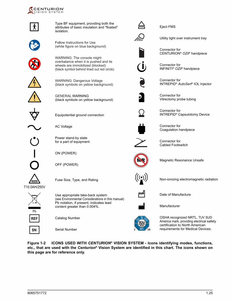
8065751772 1.25
Figure 1-2 ICONS USED WITH CENTURION® VISION SYSTEM - Icons identifying modes, functions, etc., that are used with the Centurion® Vision System are identified in this chart. The icons shown on this page are for reference only.
Eject FMS
Utility light over instrument tray
Connector forCENTURION® OZil® handpiece
Connector forINFINITI® OZil® handpiece
Connector forINTREPID® AutoSert® IOL Injector
Connector forVitrectomy probe tubing
Connector forINTREPID® Capsulotomy Device
Connector forCoagulation handpiece
Connector forCabled Footswitch
Magnetic Resonance Unsafe
Non-ionizing electromagnetic radiation
Date of Manufacture
Manufacturer
OSHA recognized NRTL, TUV SUDAmerica mark, providing electrical safetycertification to North Americanrequirements for Medical Devices.
Type BF equipment, providing both theattributes of basic insulation and "floated"isolation.
Follow Instructions for Use(white figure on blue background)
WARNING: The console mightoverbalance when it is pushed and itswheels are immobilized (blocked)(black symbol behind lined out red circle)
WARNING: Dangerous Voltage(black symbols on yellow background)
GENERAL WARNING (black symbols on yellow background)
Equipotential ground connection
AC Voltage
Power stand-by statefor a part of equipment
ON (POWER)
OFF (POWER)
Fuse Size, Type, and Rating
Use appropriate take-back system(see Environmental Considerations in this manual)Pb notation, if present, indicates leadcontent greater than 0.004%.
Catalog Number
Serial Number
Pb
SN
REF
T10.0AH/250V
MR
SUD
C US
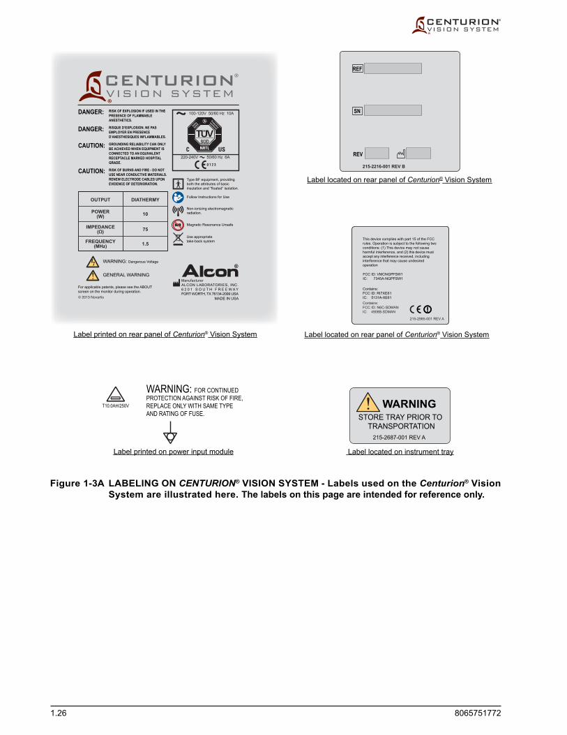
1.26 8065751772
Figure 1-3A LABELING ON CENTURION® VISION SYSTEM - Labels used on the Centurion® Vision System are illustrated here. The labels on this page are intended for reference only.
215-2216-001 REV B
Label printed on rear panel of Centurion® Vision System Label located on rear panel of Centurion® Vision System
Label printed on power input module
Label located on rear panel of Centurion® Vision System
Label located on instrument tray
T10.0AH/250V
WARNING: FOR CONTINUEDPROTECTION AGAINST RISK OF FIRE,REPLACE ONLY WITH SAME TYPEAND RATING OF FUSE.
®
© 2013 Novartis
For applicable patents, please see the ABOUTscreen on the monitor during operation.
ManufacturerALCON LABORATORIES, INC.6 2 0 1 S O U T H F R E E W A YFORT WORTH, TX 76134-2099 USA
MADE IN USA
®
®
DANGER:
DANGER:
CAUTION:
CAUTION:
RISK OF EXPLOSION IF USED IN THEPRESENCE OF FLAMMABLEANESTHETICS.
RISQUE D’EXPLOSION. NE PASEMPLOYER EN PRESENCED’ANESTHESIQUES INFLAMMABLES.
GROUNDING RELIABILITY CAN ONLYBE ACHIEVED WHEN EQUIPMENT ISCONNECTED TO AN EQUIVALENTRECEPTACLE MARKED HOSPITALGRADE.
RISK OF BURNS AND FIRE - DO NOTUSE NEAR CONDUCTIVE MATERIALS.RENEW ELECTRODE CABLES UPONEVIDENCE OF DETERIORATION.
This device complies with part 15 of the FCCrules. Operation is subject to the following twoconditions: (1) This device may not causeharmful interference, and (2) this device mustaccept any interference received, includinginterference that may cause undesiredoperation
FCC ID: VMCNGPFSW1IC: 7345A-NGPFSW1
Contains:FCC ID: RI7XE61IC: 5131A-XE61Contains:FCC ID: N6C-SDMANIC: 4908B-SDMAN
215-2985-001 REV A
REF
SN
REV
215-2687-001 REV A
STORE TRAY PRIOR TOWARNING
TRANSPORTATION
WARNING: Dangerous Voltage
GENERAL WARNING
Type BF equipment, providingboth the attributes of basicinsulation and “floated” isolation.
Follow Instructions for Use
Non-ionizing electromagneticradiation.
Magnetic Resonance Unsafe
Use appropriatetake-back system
MR

8065751772 1.27
Figure 1-3B LABELING ON CENTURION® VISION SYSTEM - Labels used on the Centurion® Vision System are illustrated here. The labels on this page are intended for reference only.
Label located on back of remote control
Label located on bottom of footswitch
215-3061-001 REV A© 2013 Novartis
(2) "AA" / LR6
REMOTE CONTROLFollow Instructions for Use
Use appropriatetake-back system
ManufacturerALCON LABORATORIES, INC.6 2 0 1 S O U T H F R E E W A YFORT WORTH, TX 76134-2099 USAMADE IN USA
SN
8065751774REF
IPX1Date of Mfg
0123
215-1994-001 REV. P14© 2012 Novartis
ManufacturerALCON LABORATORIES, INC.6 2 0 1 S O U T H F R E E W AYFORT WORTH, TX 76134-2099 USA MADE IN USA
8065751762
IPX6
FOOTSWITCHThis device complies with part 15 of the FCC Rules. Operation is subject to the following two conditions: (1) This device may not cause harmful interference, and (2) this device must accept any interference received including interference that may cause undesired operation.
FCC ID: VMCNGPFSW1IC: 7345A - NGPFSW1CONTAINS
Non-ionizing electromagneticradiationUse appropriate take-back system
IC: 5131A-XE61FCC ID: RI7XE61
Follow Instructions for Use
Date of Manufacture
GENERAL WARNING
For applicable patents, please see the “ABOUT” screen on the monitor during operation.
215-1016-502 REVREF
SN
REV
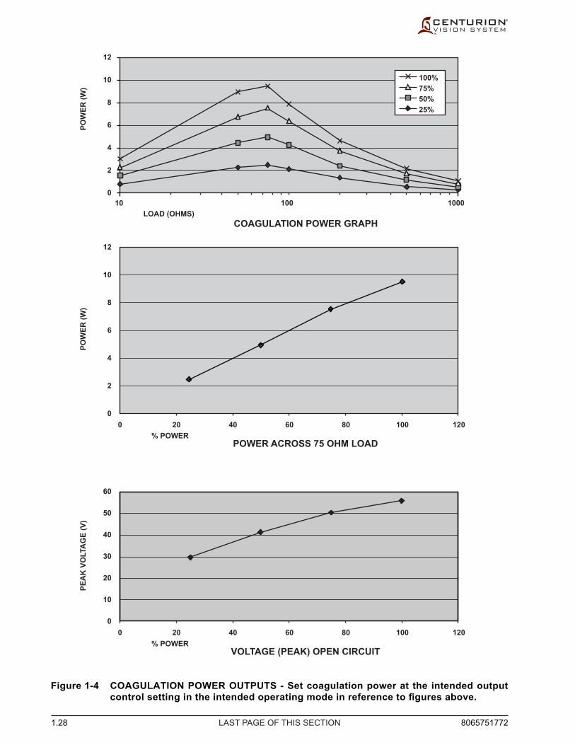
1.28 8065751772LAST PAGE OF THIS SECTION
Figure 1-4 COAGULATION POWER OUTPUTS - Set coagulation power at the intended output control setting in the intended operating mode in reference to figures above.
COAGULATION POWER GRAPHLOAD (OHMS)
POW
ER (W
)
VOLTAGE (PEAK) OPEN CIRCUIT% POWER
0 20 40 60 80 100 120
PEA
K V
OLT
AG
E (V
)
60
50
40
30
20
10
0
POWER ACROSS 75 OHM LOAD% POWER
POW
ER (W
)
0 20 40 60 80 100 120
12
10
8
6
4
2
0
12
10
8
6
4
2
010 100 1000
25% 50% 75% 100%

8065751772 1.29
Doctor Settings No. General Doctor Setting Default 3 Patient Eye Level Offset Default (PEL) -5 4 Irrigation Pressure Drop 60 5 Reflux Pressure Offset 30 6 Vent Time 0 7 Continuous Irrigation Mode Default OFF 8 Continuous Irrigation Auto-Off Threshold 5 11 Verify PEL Enabled 12 Estimated Incision Leakage 0 13 AutoSert® Full Extension Offset 0 14 AutoSert® Remote Control Default Preload Lens 15 Vitrectomy Setup ON
IP Settings No. Phaco IP Doctor Setting Default 1 Phaco IP Longitudinal Pulse Duration 10 2 Phaco IP Vacuum Threshold 95 3 Phaco IP Longitudinal Power 100
Default Procedures No. Default Procedure Procedure Description Default Steps 1 Procedure 1 Divide and Conquer PrePhaco, Sculpt, Quad, Epi, Cortex, Polish, Visco 2 Procedure 2 Phaco Chop PrePhaco, Chop, Epi, Cortex, Polish, Visco 3 Procedure 3 Vitrectomy Vitrectomy (Anterior Vitrectomy Mode), Vitrectomy (Epinucleus Removal Mode), Vitrectomy (I/A Cut Mode), Vitrectomy (Peripheral Iridectomy Mode), Vitrectomy (Visco Aspiration Mode)
Active Irrigation Surgical Parameters No. Procedure Surgical Parameter Default 1 IOP Ramp Time 1.0
I/A Step Passive Irrigation Surgical Parameters No. I/A Step Surgical Parameter Default 1 Irrigation Pressure 78
I/A Steps Active Irrigation Surgical Parameters No. I/A Step Surgical Parameter Default 1 Flow Compensation 1.0
I/A Steps Fluidics Parameters Cortex Polish Visco B/E Range 2 IOP 20/55 20/55 20/55 Control in Range 1 IOP Fixed Fixed Fixed Control in Range 2 IOP Fixed Fixed Fixed B/E Vacuum 0/500 0/20 0/650 Control in Range 2 Vacuum Linear Linear Fixed B/E Asp Rate 0/35 0/10 0/50 Control in Range 2 Asp Rate Fixed Linear Linear Vacuum Rise Time 0 0 0
Phaco Step Passive Irrigation Surgical Parameters No. Phaco Step Surgical Parameter Default 1 Irrigation Pressure 95
Phaco Step Active Irrigation Surgical Parameters No. Phaco Step Surgical Parameter Default 1 Flow Compensation 1.0
Table 1-7 SUMMARY OF ALCON DEFAULT SETTINGS

1.30 8065751772
UltraChop Phaco Steps Active Irrigation Surgical Parameters No. Phaco Step Surgical Parameter Default 1 Flow Compensation 1.0
Phaco Steps Fluidics Parameters PrePhaco UltraChop Chop Sculpting Quadrant Epinucleus Flip B/E/E IOP 20/55/55 20/55/55 20/55/55 20/55/55 20/55/55 20/55/55 20/55/55 Control in Range 1 IOP Fixed Fixed Fixed Fixed Fixed Fixed Fixed Control in Range 2 IOP Fixed Fixed Fixed Fixed Fixed Fixed Fixed Control in Range 3 IOP Fixed Fixed Fixed Fixed Fixed Fixed Fixed B/E/E Vacuum 0/180/180 0/380/380 0/380/380 0/ 80/80 0/380/380 0/380/ 380 0/380/380 Control in Range 2 Vacuum Fixed Fixed Fixed Fixed Fixed Linear Fixed Control in Range 3 Vacuum Fixed Fixed Fixed Fixed Fixed Fixed Fixed B/E/E Asp Rate 0/30/30 0/40/40 0/40/40 0/23/23 0/40/40 0/30/30 0/40/40 Control in Range 2 Asp Rate Fixed Fixed Fixed Fixed Fixed Linear Fixed Control in Range 3 Asp Rate Fixed Fixed Fixed Fixed Fixed Fixed Fixed Vacuum Rise Time 0 0 0 0 0 0 0
Phaco Step Surgical Parameters No. Phaco Step Surgical Parameter Default 1 Phaco IP ON 2 Phaco Mode Continuous
Continuous Phaco Mode Parameters PrePhaco UltraChop Chop Sculpting Quadrant Epinucleus Flip B/E Longitudinal 0/0 0/0 0/0 0/0 0/0 0/0 0/0 Control Longitudinal Linear Linear Linear Linear Linear Linear Linear B/E Torsional 0/20 0/60 0/60 0/60 0/60 0/60 0/60 Control Torsional Linear Linear Linear Linear Linear Linear Linear
Pulsed Phaco Mode Parameters PrePhaco UltraChop Chop Sculpting Quadrant Epinucleus Flip B/E Longitudinal 0/0 0/0 0/0 0/0 0/0 0/0 0/0 Control Longitudinal Linear Linear Linear Linear Linear Linear Linear B/E Torsional 0/20 0/60 0/60 0/60 0/60 0/60 0/60 Control Torsional Linear Linear Linear Linear Linear Linear Linear B/E Longitudinal DC 0/0 0/0 0/0 0/0 0/0 0/0 0/0 Control Longitudinal DC Fixed Fixed Fixed Fixed Fixed Fixed Fixed B/E Torsional DC 0/80 0/80 0/80 0/80 0/80 0/80 0/80 Control Torsional DC Fixed Fixed Fixed Fixed Fixed Fixed Fixed B/E Pulse Rate 1/20 1/20 1/20 1/20 1/20 1/20 1/20 Control Pulse Rate Fixed Fixed Fixed Fixed Fixed Fixed Fixed
Burst Phaco Mode Parameters PrePhaco UltraChop Chop Sculpting Quadrant Epinucleus Flip B/E Longitudinal 0/0 0/0 0/0 0/0 0/0 0/0 0/0 Control Longitudinal Linear Linear Linear Linear Linear Linear Linear B/E Torsional 0/20 0/60 0/60 0/60 0/60 0/60 0/60 Control Torsional Linear Linear Linear Linear Linear Linear Linear B/E Longitudinal On 2/35 2/35 2/35 2/35 2/35 2/35 2/35 Control Longitudinal On Fixed Fixed Fixed Fixed Fixed Fixed Fixed B/E Torsional On 2/70 2/70 2/70 2/70 2/70 2/70 2/70 Control Torsional On Fixed Fixed Fixed Fixed Fixed Fixed Fixed B/E Off 2500/0 2500/0 2500/0 2500/0 2500/0 2500/0 2500/0
IOL Injection Step Parameters Default IOL Plunger Type Standard Initial IOL Injection Rate 1.7 IOL Injection Pause Time 3.0 Beginning IOL Injection End Rate 1.2 Ending IOL Injection End Rate 1.7 Control of IOL Injection Rate Linear

8065751772 1.31
Coagulation Step Parameters No. Coagulation Step Surgical Parameter Default 1 Beginning Coagulation Power 0 2 Ending Coagulation Power 50 3 Control of Coagulation Power Fixed
Vitrectomy Modes Passive Irrigation Parameters Anterior Vitrectomy Epinucleus Removal Peripheral Iridectomy Visco Aspiration I/A Cut Irrigation Pressure 65 65 65 65 65
Vitrectomy Steps Active Irrigation Surgical Parameters No. Vitrectomy Step Surgical Parameter Default 1 Flow Compensation 1.4
Stand-Alone Vitrectomy Step Active Irrigation Surgical Parameters No. Stand-Alone Vitrectomy Step Surgical Parameter Default 1 Flow Compensation 1.4 2 IOP Ramp Time 1.0
Vitrectomy Modes Active Irrigation Parameters Anterior Vitrectomy Epinucleus Removal Peripheral Iridectomy Visco Aspiration I/A Cut B/E/E IOP 20/55 20/55 20/55 20/55 20/55/55 Control in Range 1 IOP Fixed Fixed Fixed Fixed Fixed Control in Range 2 IOP Fixed Fixed Fixed Fixed Fixed Control in Range 3 IOP N/A N/A N/A N/A Fixed Vacuum Rise Time 0 0 0 0 0
Vitrectomy Modes Fluidics Parameters Anterior Vitrectomy Epinucleus Removal Peripheral Iridectomy Visco Aspiration I/A Cut B/E/E Vacuum 0/350 0/500 0/350 0/650 0/350/500 Control in Range 2 Vacuum Linear Linear Linear Linear Linear Control in Range 3 Vacuum N/A N/A N/A N/A Fixed B/E/E Asp Rate 0/10 0/10 0/10 0/50 0/ 10/20 Control in Range 2 Asp Rate Fixed Linear Fixed Fixed Fixed Control in Range 3 Asp Rate N/A N/A N/A N/A Fixed
Vitrectomy Modes Parameters Anterior Vitrectomy Epinucleus Removal Peripheral Iridectomy Visco Aspiration I/A Cut B/E Range 2 Cut Rate 1/4000 1500/500 N/A/1 1/4000 N/A Control in Range 2 Cut Rate Fixed Linear N/A Fixed N/A B/E Range 3 Cut Rate N/A N/A N/A N/A 1/4000 Control in Range 3 Cut Rate N/A N/A N/A N/A Fixed
Irrigation Footswitch Step Passive Irrigation Surgical Parameters No. Irrigation Footswitch Step Surgical Parameter Default 1 Irrigation Pressure 78
Irrigation Footswitch Step Active Irrigation Surgical Parameters No. Irrigation Footswitch Step Surgical Parameter Default 1 Beginning Range 2 IOP Target 20 2 Ending Range 2 IOP Target 55 3 Control in Range 1 IOP Target Linear 4 Control in Range 2 IOP Target Fixed

1.32 8065751772LAST PAGE OF THIS SECTION
THIS PAGE INTENTIONALLY BLANK

8065751772 2.1
DESCRIPTION OF CENTURION® VISION SYSTEM
Description Alcon’s Centurion® Vision System is a multi microprocessor-controlled ophthalmic
surgical instrument with associated memory and input/output (I/O) circuitry. The systemcommunicatestotheuserviaitsFrontPaneldisplay,withvoiceconfirmations,and with tones. An automatic self-test is initiated each time system power is turned on.
This test checks a variety of functions including the following:
• HostCPUAssembly(includingDisplay&Touchscreen) • FootswitchInterface • MultifunctionAssembly • FluidicsAssembly • Active Fluidics™ Assembly • PhacoAssembly • IVPoleAssembly • PneumaticsAssembly
When the system successfully completes the self-test, it automatically goes into the Setup mode. If the system fails the self-test, an Event message is displayed.
Thissectionofthemanualisbrokenintotwomajorparts.Thefirstpartdescribestheconsole and its accessories. All the parts of the system will be described, including the display panel, Active Fluidics™ system,gravityfluidicssystem,connectors,fluidicsinterface, footswitch, remote control, and VideOverlay system. The second part of this section describes the operator interface. This is where the display screens for system setup, surgery, programming, and dialogs are shown.
Trademark Note A button, mode, or step labeled OZil®, AutoSert®, or UltraChop refers to a display
screen control used with an OZil® torsional handpiece, INTREPID® AutoSert® IOL injector, or ALCON® UltraChopper® tip, respectively.
SECTION TWODESCRIPTION

2.2 8065751772
CENTURION® VISION SYSTEM CONSOLE AND ACCESSORIES
DESCRIPTION OF CONSOLE
Fluidics Module
Thefluidicsmoduleislocatedinthecenterofthefrontpanel.Themoduleallowsfast and easy insertion of the Fluidic Management System (FMS; i.e., cassette), and because the module contains all the connections required, surgery can be started with minimal delay.
Figure 2-1 The Console - The console contains all the controls, connectors, and communication devices required by the surgeon to perform cataract lens extraction surgery.
Locking Caster Wheels (4)
Accessory Drawer
Standby Power Switch
Handle Bar
Connectors forWired Footswitch
Speakers (3)
Adjustable Instrument Tray
IR Remote Control
Fluidics Module
Convenience Lamp
Front Display Paneland Touch Screen
Wireless Footswitch
Rotating Work Surfaceand Locking Ring(Active Fluidics™ Bag Bayunderneath Work Surface)

8065751772 2.3
Figure 2-2 The Front Panel Connectors - The front connector panel allow quick and easy connection of handpieces and consumables.
Front Display Panel and Touch Screen The front display panel tilts and rotates, allowing easy maneuverability during setup and
surgery. For storage and transport, the front panel folds down. The front display is the user'smainsourceofsystemcontrol,allowingfingertipcommandofsystemfunctions.
Adjustable Instrument Tray The Centurion® Vision system provides an adjustable instrument tray within the
sterilefield.Thetrayiscapableofaccommodatingavarietyofpositionsintheoperating room environment—right, left, front, and rear of the surgeon—and the tray is height adjustable. There are curved metal rods on the tray that allow for creation of sterile pouches when covered with a sterile tray support cover, and also provide cradles for the IR remote control. Two rubber clips are built into the tray surface to neatly secure the handpiece cables and tubing up and off unsterilized surfaces.
CAUTIONThe maximum weight allowed on the instrument tray is 9.1 kg (20 lb.)
Front Panel Connectors The front panel connectors are located on both sides of the fluidicsmodule.The
front panel connectors provide three self-locking phaco handpiece connectors, two connectors for the INTREPID® AutoSert® IOL Injector, one connector for a bipolar coagulation handpiece, connectors for the INTREPID® Capsulotomy Device, and luer lock pneumatic connectors for the Centurion® UltraVit® Probe. The left row of connectors also includes a utility light for the instrument tray. Symbols near the connectorsfacilitatehandpieceidentification.
The CENTURION® OZil® handpiece is recognized in the top two phaco handpiece connectors; only the INFINITI® OZil® handpiece is recognized in the bottom. Only one phaco handpiece can be connected at one time in either connector, unless the UltraChop feature is enabled in which case the system will accept two phaco handpieces.
Coagulation Handpiece
Vitrectomy Handpiece
Utility Light forInstrument Tray CENTURION® OZil® Handpiece
INTREPID® AutoSert® IOL Injector
INTREPID® Capsulotomy Device
INFINITI® OZil® Handpiece
Fluidics Module

2.4 8065751772
Standby Power Switch This pushbutton switch is used to turn secondary power ON and OFF. If system
freezesandisunresponsivetooperatorcommands,pressStandbyswitchforfiveseconds to shut down system, then re-boot.
Accessory Drawer One drawer allows storage of miscellaneous accessories.
Audio Speakers Three audio speakers are located on the front and each side of the console. These
speakersproducevoiceconfirmations,inconjunctionwithmultipletones, to allow the Centurion® Vision System to communicate with the user. Audible tones are generated to indicate a change in the operating mode and to alert the operator of certain conditions such as an occluded line. Additionally, a varied pitch tone is generated to audibly indicate vacuum levels; the pitch increases as the vacuum level increases. Speaker volumes are adjustable via the Custom menus.
Irrigating Fluid Escape
Active Fluidics™ Bag Bay
Footswitch Hanger
AC Power Cord Hanger
Input/Output (I/O) Connector Panel
Wireless FootswitchCharging Station
Primary AC Power Switch
Rotating Work Surface
Power IV Pole and Hangerfor Gravity Fluidics
Figure 2-3 Rear and Side Panels

8065751772 2.5
Locking Caster Wheels Four large caster wheels support the Centurion® Vision System. The wheels rotate
360º for ease of system mobility, and all four wheels have a locking lever to secure the system in place. The wheels should always be locked when the unit is in use, and unlocked when being moved.
Handle Bar A handle bar wraps around the sides and back of the Centurion® Vision System, and
should always be used to move it.
CAUTIONThe system must be moved carefully, otherwise it could tip over and become damaged. Do not push or pull the unit by the display, the instrument tray, or the IV pole. The handle bar is provided for moving the instrument. The unit should be pulled and not pushed, especially over elevator and door thresholds.
Equipotential Ground Connector The equipotential ground connector may be used to provide a direct connection
between the Centurion® system and the potential equalization bus-bar of the electrical installation. This connector complies to the requirements of IEC/EN 60601-1.
AC Power Cord Hanger Used to store the power supply cord when system is out of use. Located in the middle
of the rear panel.
Primary AC Power Switch The power module contains an AC power switch, AC power connector, and a fuse
holder. The power module is located at the bottom of the rear panel. A standby power switch is located at the top of the right side panel.
• ACPowerConnector-PowercordfromACpoweroutletconnectshere.Ahospital grade power cord must be used.
• PrimaryACPowerSwitch-ConnectsACpowertopowersupply. • Fuse Door - Open the fuse door to gain access to the fuse holder. Refer to label on
back of system to identify fuse size and type.
Footswitch Hanger / Charging Station When out of use, the wireless footswitch hangs on the back of the Centurion® Vision
System. If used wirelessly, its internal lithium ion battery is charged inductively through the rear panel. If wired to the system, and system power is turned on, the footswitch battery is charged through the cable.
Input/Output (I/O) Connector Panel This panel contains inputs and outputs for Audio input, USB communications,
VideOverlay output (RS232), and Ethernet internet communications (RS422). An antenna for wireless communications is also located on this panel.
The USB port is provided for Service functions and for backing up and restoring Dr. memory. Plugging any other USB device into the port is not recommended.

2.6 8065751772
Rotating Work Surface A versatile rotating work surface is provided on the top of the Centurion® Vision
System. When stowed, this work surface covers the Active Fluidics™ bag bay and is locked in place. When open it allows the user to lower a bag of BSS® irrigatingfluidinto the bag bay.
To rotate the work surface and reveal the bag bay, press and hold the locking ring while pressing sideways on the work surface (see left image in Figure 2-4). The right image shows the work surface in the open position, allowing access to the bag bay. Once open, the surface can be rotated until the mechanical lockout feature prevents further rotation. When Active Fluidics™ technology is used, this lockout feature prevents inadvertent contact of the work surface against the bag of BSS® irrigating fluidanditstubing.Toreturntheworksurfacebacktoitsstowedposition,pressandhold the locking ring and press sideways on the work surface.
CAUTIONS• The maximum weight allowed on the rotating surface is 4.55 kg (10 lb.)• Work surface must not come in contact with bag of irrigating fluid.
Figure 2-4 Rotating Work Surface - To rotate working surface and gain access to the Active Fluidics™ bag bay, press down on locking ring and rotate work surface out of the way.
8065751772 2.7
FLUIDICS ADMINISTRATION
The Centurion® Vision system supports two types of fluidicsadministrationtodeliverandcontrolfluidicsfluidpressure:Gravity Fluidicsisusedforfluidadministrationusingthepower IV pole, and Active Fluidics™ technology is an automated system that administers fluidfromabagofBSS® irrigatingfluidwithinitsbagbay(seeFigure2-3).
Power IV Pole and Hanger for Gravity Fluidics ForgravityfluidicsacontainerofBSS®irrigatingfluidishungfromahangerontop
of the IV pole. Raising and lowering the pole increases and decreases the irrigation pressure delivered to the tip of the handpiece. The hanger can be installed in 45° increments by releasing the chrome nut at the bottom of the IV pole, lifting the pole up, and setting it back down at the desired angle.
Bag Bay for Active Fluidics™ Technology For Active Fluidics™ technology a bag of BSS®irrigatingfluidiscompressed
between two plates within the Active Fluidics™ bag bay, located under the rotating work surface on the top of the console. The pressure created by compressing the bagofirrigatingfluidismonitoredtoprovideanaccuratepressuresource,allowingcontrol of intraocular pressure (IOP).
This precise pressure control creates the opportunity to tailor IOP performance based on surgical preference. There are two functions related to Active Fluidics™ technology which allow the surgeon to tailor IOP performance: Irrigation Factor and IOP Ramp. These functions are described later in this section of the manual (Fluidics Controls).
WARNING!Use of BSS® irrigating fluid bags other than those approved by Alcon for use in the Active Fluidics™ system can result in patient injury or system damage.
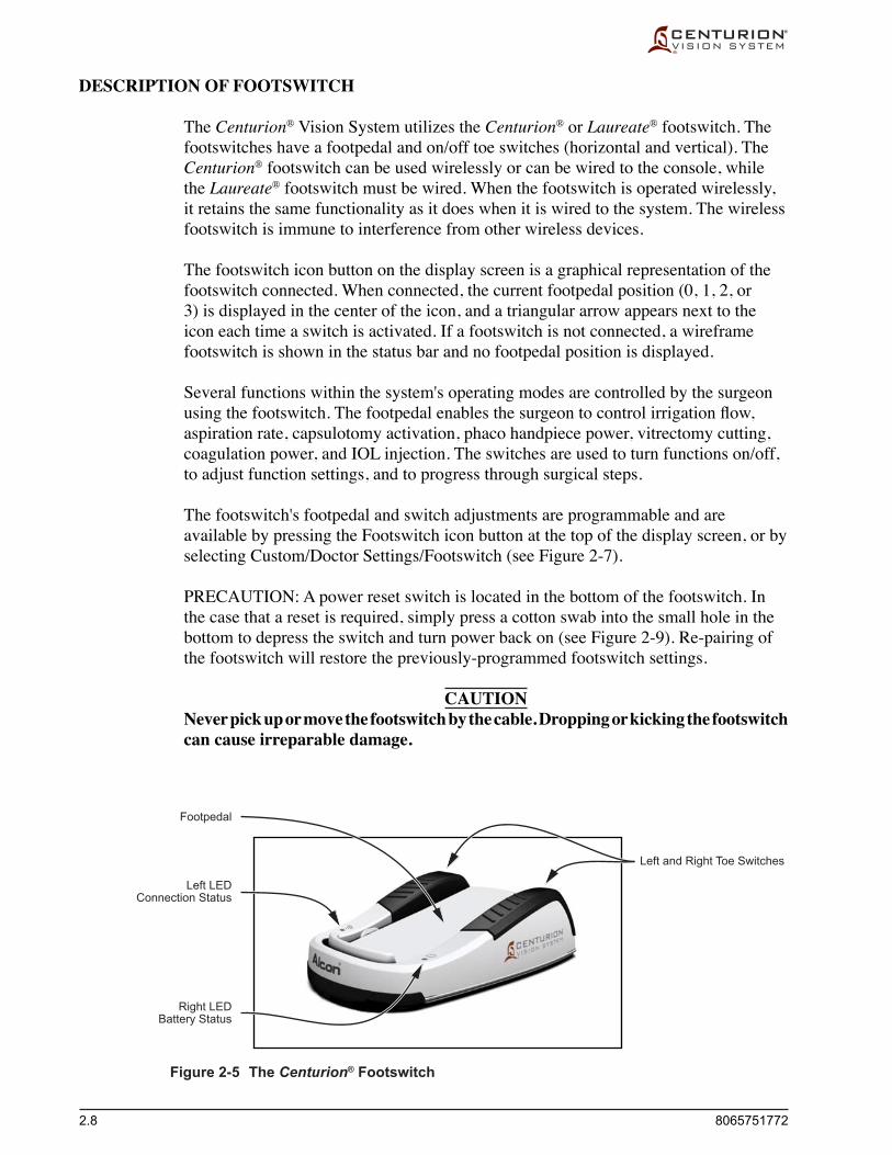
2.8 8065751772
Left LEDConnection Status
Right LEDBattery Status
Footpedal
Left and Right Toe Switches
DESCRIPTION OF FOOTSWITCH
The Centurion® Vision System utilizes the Centurion® or Laureate® footswitch. The footswitches have a footpedal and on/off toe switches (horizontal and vertical). The Centurion® footswitch can be used wirelessly or can be wired to the console, while the Laureate® footswitch must be wired. When the footswitch is operated wirelessly, it retains the same functionality as it does when it is wired to the system. The wireless footswitch is immune to interference from other wireless devices.
The footswitch icon button on the display screen is a graphical representation of the footswitch connected. When connected, the current footpedal position (0, 1, 2, or 3) is displayed in the center of the icon, and a triangular arrow appears next to the icon each time a switch is activated. If a footswitch is not connected, a wireframe footswitch is shown in the status bar and no footpedal position is displayed.
Several functions within the system's operating modes are controlled by the surgeon usingthefootswitch.Thefootpedalenablesthesurgeontocontrolirrigationflow,aspiration rate, capsulotomy activation, phaco handpiece power, vitrectomy cutting, coagulation power, and IOL injection. The switches are used to turn functions on/off, to adjust function settings, and to progress through surgical steps.
The footswitch's footpedal and switch adjustments are programmable and are available by pressing the Footswitch icon button at the top of the display screen, or by selecting Custom/Doctor Settings/Footswitch (see Figure 2-7).
PRECAUTION: A power reset switch is located in the bottom of the footswitch. In the case that a reset is required, simply press a cotton swab into the small hole in the bottom to depress the switch and turn power back on (see Figure 2-9). Re-pairing of the footswitch will restore the previously-programmed footswitch settings.
CAUTIONNever pick up or move the footswitch by the cable. Dropping or kicking the footswitch can cause irreparable damage.
Figure 2-5 The Centurion® Footswitch

8065751772 2.9
Footpedal Control Footpedal positions are shown in Figure 2-6, and footpedal positions/functions in each
mode of operation are listed in Table 2-1. Footpedal control can be programmed for each doctor's personal preferences by pressing the Footswitch icon button at the top of the display screen, or by selecting Custom/Doctor Settings/Footswitch (see Figure 2-7).
Depending on the surgery step, the user may have the option to select linear or fixed footpedal control of a surgical parameter (i.e., aspiration, vacuum, power, coagulation). With linear footpedal control, the angle of depression within the pedal range is directly proportional to the parameter output. The parameter output is 0 at
Figure 2-6 Diagram of Footpedal Positions
Table 2-1 Table of Footpedal Positions - The footpedal is used by the surgeon to control several surgical functions. This table shows the functions controlled, dependent on mode of operation and type of irrigation selected. As the footpedal is depressed it travels from the resting position into its active positions.
POSITION 0
POSITION 1
POSITION 2
POSITION 3
resting position
detent 1
detent 2
full footpedal depression
FOOTSWITCH ASSEMBLY
FOOTPEDAL
Footpedal Control of Surgical Functions
Position Position Position Position Mode 0 1 2 3
Capsulotomy Resting Capsulotomy
Resting Irrigation Irrigation/Aspiration Irrigation/Aspiration/ Phaco Power Phaco Continuous Irrigation Irrigation/Aspiration Irrigation/Aspiration Phaco Power
I/A Resting Irrigation Irrigation/Aspiration
Continuous Irrigation Irrigation/Aspiration
AutoSert® Resting IOL Injection Rate Injector Initial Velocity, Pause Time, End Velocity
Coag Resting Coagulation Power
Anterior Vit Resting Irrigation Irrigation/Aspiration Epi Removal Cutting Peripheral Irid Visco Asp Continuous Irrigation Irrigation/Aspiration Cutting
Resting Irrigation Irrigation/Aspiration Irrigation/Aspiration/ Cutting I/A Cut Continuous Irrigation Irrigation/Aspiration Irrigation/Aspiration Cutting

2.10 8065751772
the very start of the treadle range, and the parameter output is equal to the limit value specifiedattheendofthetreadlerange.Withfixed footpedal control, the parameter outputisfixedatitslimitvaluethroughoutthetreadlerange.
Figure 2-7 Doctor Settings Dialog Screen - Footswitch Tab
Figure 2-8 Doctor Settings Dialog Screen - Button Assignment SelectionsPressing one of the Button Assignment buttons brings up a drop-down menu of functions that can be activated with the surgeon's toe. Several selections are hidden below the selections shown here; the slide bar on the right is used to expose the other selections.

8065751772 2.11
Footswitch Range Spans The footswitch's footpedal spans in each Range are programmable and are available
by pressing the Footswitch icon button at the top of the display screen, or by selecting Custom/Doctor Settings/Footswitch (see Figure 2-7). The span of Range 0 is always set at 0 to 5 % of the footpedal range, while Ranges 1, 2, and 3 can be changed in the Footswitch Range Spans (%) window.
Detent Footpedal detents identify the transition from one footpedal position to another. When
turned On, the footpedal vibrates when pressing through the detent from one position into the next. The vibration power can be adjusted up and down with the two Strength arrow keys.
Toe Switch Control The footswitch has left and right toe switches that are assigned to control various
surgical functions. The two toe switches operate horizontally and vertically, each direction actuating a function switch, controlling up to four system functions.
If the footpedal is not depressed, any mutually exclusive switch may be engaged. If the footpedal is depressed, certain switches may or may not be allowed to engage.
Button Assignment Footswitch button assignments are programmable and are available by pressing
the Footswitch icon button at the top of the display screen, or by selecting Custom/Doctor Settings/Footswitch (see Figure 2-7). From this screen, press one of the blue oval buttons next to the footswitch and select a function from the dropdown list (see Figure 2-8).
Thelefthorizonalswitchistheonlyswitchwithafactorydefaultaction:Reflux.TheRefluxfunctioncanbeselectedforanotherswitch,allowingthelefthorizontalswitchtobegivenanotherfunction.TheRefluxfunctionmustalwaysbeassignedtoaswitch.
The other three switches are listed as None by default, their functions are mutually exclusive, and each must be programmed by the user. When a switch is given a function already designated to another switch, the other switch is given a None designation. ChoicesareReflux,IrrigationPressure+,IrrigationPressure-,IrrigationPressure+/-,ContinuousIrrigation,Step+,Step-,andNone.

2.12 8065751772
•Reflux The Refluxswitchhastriplefunctionality.Inmostmodesofoperationtheswitch
functionisReflux,whilewithintheAutoSert® injector step the switch function is to Retract the plunger. One other exception is that in the Capsulotomy step it is used to Enable the capsulotomy function. At least one toe switch must be dedicated to the Refluxfunction.
Reflux:ThedefaultrefluxpressureisequaltothecurrentbottleheightIOPpressure.TherefluxpressurecanbeincreasedusingtheRefluxOffsetcontrolintheCustom/Doctor Settings/Fluidics menu.Inallcases,refluxisnotavailablewhenthefootpedal is depressed, and is not available in a Coagulation step.
Retract: In the AutoSert® injector step this switch moves the plunger in a reverse direction. Control of this function is not allowed while the footpedal is depressed.
Enable: In the Capsulotomy step this switch enables the capsulotomy function.
•IrrigationPressure+,IrrigationPressure- Whenusinggravityfluidics,atoeswitchcanbeselectedtomovetheIVpoleupand
down to increase or decrease the irrigation pressure. These toe switch assignments are not functional when Active Fluidics™ technology is in use.
•IrrigationPressure+/-Whenusinggravityfluidics,thisswitchassignmentisusedto increase irrigation pressure by pressing and releasing the switch, and to reduce irrigation pressure by pressing and holding the switch. This toe switch assignment is not functional when Active Fluidics™ technology is in use.
•Continuous Irrigation Delegating Continuous Irrigation to a switch on the footswitch allows the user to turn
Continuous Irrigation on and off, whether or not it is enabled for the selected doctor.
•Step+,Step– Aswitchmaybeassignedasstepadvance(Step+)orstepback(Step–).TheSetup,
Coagulation, and Anterior Vitrectomy steps are excluded from this stepping sequence. If step advance or step back is assigned, when the switch is pressed, the next or previous step to the current step is selected in the surgery menu.
•None - This selection is made to eliminate functionality from the switch.
Vit Cutter Button Dual Assignment When in Anterior Vitrectomy mode of operation, a selected footpedal button can be
assigned the function of enabling and disabling the vitrectomy cutter function. This button, when in other modes, has a different assignment.

8065751772 2.13
Footswitch Status LEDs Two LEDs, one on the left and one on the right of the footpedal heel, illuminate to
indicate footswitch status. The following table shows the LED display patterns with respect to the footswitch's operation state.
Table 2-2 Footswitch Status LEDs
Left LED Indicating Connection Status with Centurion® System
Color and Behavior Description Solid Blue Connected (wired or wireless) Off When footswitch is in wireless mode and not engaged*, or in
wireless mode and does not hear beacons from console, or in shipping state
Right LED Indicating Battery Status
Color and Behavior Description Solid Green Battery level > 40 % of usable range Solid Yellow Battery level ≤ 40 % of usable range Blinking Green Battery level > 40 % while charging Blinking Yellow Battery level ≤ 40 % while charging Off When footswitch is in wireless mode and not engaged*, or in
shipping state
* LEDs remain on/blinking for a few seconds after disengagement of the footswitch; i.e., not pressing on the footpedal or any of the footswitch buttons.
Charging Footswitch Battery The footswitch battery can be charged using two different methods: • The footswitch can be charged wirelessly by cradling it on Centurion® system
footswitch hanger on the rear panel of the console. • The footswitch can be charged by cabling it to the connector at the bottom of the
Centurion® front panel. With system power turned on, the battery will be charged through the cable.
Pairing Footswitch with Centurion® System Tochangethewirelesschannelforthefootswitch,thefootswitchmustfirstbecradled
onto the back of the system. This "pairs" the footswitch with the system and allows the wireless channel to be changed in the Custom / System Settings / Wireless tab. Note that since the wireless footswitch and the Surgical Guidance System (SGS) device share the same network, changing the wireless channel for the footswitch will require a re-pairing of the SGS device.

2.14 8065751772
Footswitch Connectors
Centurion® System
Laureate® System
Spring-Loaded Ball Plungers
Rubber Sole
Spring-Loaded Ball Plungers
Reset Switch
Figure 2-9 Bottom of Centurion® System Footswitch
Footswitch Floor Security The Centurion® footswitch has four spring-loaded ball plungers at each corner of the
bottom plate (see Figure 2-9). These ball plungers are designed to allow easy sliding ofthefootswitchonasmoothfloor,andyetstilloffersecurefloorgriptionwhentheweight of the surgeon's foot is resting upon it.
The weight of the surgeon's foot on the footswitch causes the spring-loaded ball plungers to collapse, allowing the footswitch to rest on its rubber sole, thus preventingitfromslidingonthefloor.Thetensionofthespring-loadedballplungersisadjustabletothesurgeon'spreferenceusingawide,flat-tipscrewdriver.Simplyplace the screwdriver directly on top of the ball and press down until the screwdriver tip settles into the screw slot, then turn clockwise or counterclockwise to increase or decrease the spring tension.
Cabled Footswitch Connectors The Centurion® footswitch can be wired to the Centurion® Vision System, while
the Laureate® footswitch must be wired. Each footswitch cable has its own unique connector at the bottom-center of the Centurion® system's front panel (see Figure 2-10).
Figure 2-10 Cable Connectors for Cabled Footswitches
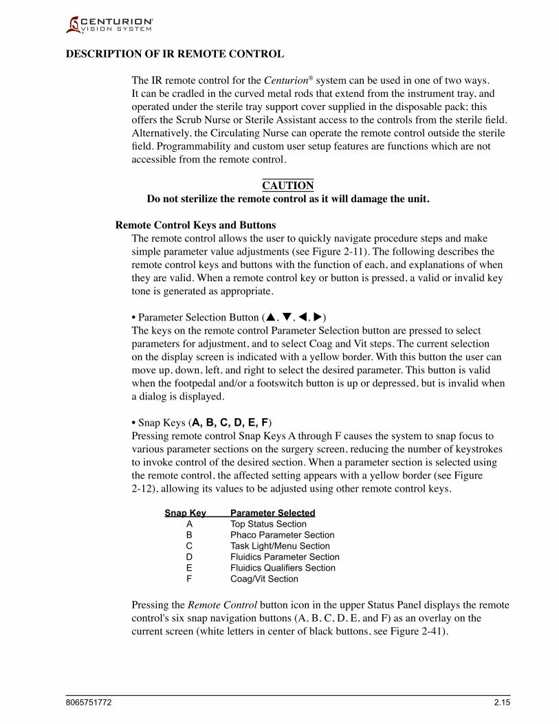
8065751772 2.15
DESCRIPTION OF IR REMOTE CONTROL
The IR remote control for the Centurion® system can be used in one of two ways. It can be cradled in the curved metal rods that extend from the instrument tray, and operated under the sterile tray support cover supplied in the disposable pack; this offerstheScrubNurseorSterileAssistantaccesstothecontrolsfromthesterilefield.Alternatively, the Circulating Nurse can operate the remote control outside the sterile field.Programmabilityandcustomusersetupfeaturesarefunctionswhicharenotaccessible from the remote control.
CAUTIONDo not sterilize the remote control as it will damage the unit.
Remote Control Keys and Buttons The remote control allows the user to quickly navigate procedure steps and make
simple parameter value adjustments (see Figure 2-11). The following describes the remote control keys and buttons with the function of each, and explanations of when they are valid. When a remote control key or button is pressed, a valid or invalid key tone is generated as appropriate.
•Parameter Selection Button (, , , ) The keys on the remote control Parameter Selection button are pressed to select
parameters for adjustment, and to select Coag and Vit steps. The current selection on the display screen is indicated with a yellow border. With this button the user can move up, down, left, and right to select the desired parameter. This button is valid when the footpedal and/or a footswitch button is up or depressed, but is invalid when a dialog is displayed.
•Snap Keys (A, B, C, D, E, F) Pressing remote control Snap Keys A through F causes the system to snap focus to
various parameter sections on the surgery screen, reducing the number of keystrokes to invoke control of the desired section. When a parameter section is selected using the remote control, the affected setting appears with a yellow border (see Figure 2-12), allowing its values to be adjusted using other remote control keys.
Snap Key Parameter Selected A Top Status Section B Phaco Parameter Section C Task Light/Menu Section D Fluidics Parameter Section E Fluidics Qualifiers Section F Coag/Vit Section
Pressing the Remote Control button icon in the upper Status Panel displays the remote control's six snap navigation buttons (A, B, C, D, E, and F) as an overlay on the current screen (white letters in center of black buttons, see Figure 2-41).

2.16 8065751772
Figure 2-11 IR Remote Control - The remote control fits securely on the instrument tray and allows rotation in any orientation. The sterile tray support cover is then draped over the remote and tray to maintain the sterile field.
Figure 2-12 Remote Control Snap Keys- Remote control snap keys A through F appear as small black buttons when the Remote Control icon button at the top of the screen is pressed. In this case the Remote Control B key was pressed to activate the Torsional (%) setting, as indicated with a yellow border. Pressing the remote + and – keys changes the torsional % value.
Snap Keys A-F
Parameter ValueAdjustment Keys
Parameter Selection Button
Enter Key
Prv and NxtNavigation Keys
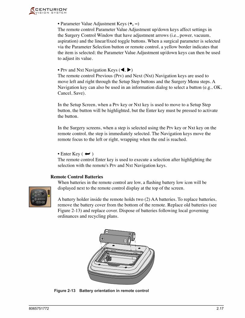
8065751772 2.17
•Parameter Value Adjustment Keys (+, –) The remote control Parameter Value Adjustment up/down keys affect settings in
the Surgery Control Window that have adjustment arrows (i.e., power, vacuum, aspiration)andthelinear/fixedtogglebuttons.Whenasurgicalparameterisselectedvia the Parameter Selection button or remote control, a yellow border indicates that the item is selected; the Parameter Value Adjustment up/down keys can then be used to adjust its value.
•Prv and Nxt Navigation Keys (, ) The remote control Previous (Prv) and Next (Nxt) Navigation keys are used to
move left and right through the Setup Step buttons and the Surgery Menu steps. A Navigation key can also be used in an information dialog to select a button (e.g., OK, Cancel, Save).
In the Setup Screen, when a Prv key or Nxt key is used to move to a Setup Step button, the button will be highlighted, but the Enter key must be pressed to activate the button.
In the Surgery screens, when a step is selected using the Prv key or Nxt key on the remote control, the step is immediately selected. The Navigation keys move the remote focus to the left or right, wrapping when the end is reached.
•Enter Key ( ) The remote control Enter key is used to execute a selection after highlighting the
selection with the remote's Prv and Nxt Navigation keys.
Remote Control Batteries Whenbatteriesintheremotecontrolarelow,aflashingbatterylowiconwillbe
displayed next to the remote control display at the top of the screen.
A battery holder inside the remote holds two (2) AA batteries. To replace batteries, remove the battery cover from the bottom of the remote. Replace old batteries (see Figure 2-13) and replace cover. Dispose of batteries following local governing ordinances and recycling plans.
Figure 2-13 Battery orientation in remote control
++ –
–

2.18 8065751772
Figure 2-14 Change Remote Channel Dialog
Select Remote Control Channel Theremotecontrolcanbeconfiguredtooperateonone-of-sixchannels.Thisfeature
allows six remote controls to independently control six Centurion® Vision Systems operating in the same room or area. Remote controls are factory preset to channel A. For proper remote operation, the Centurion® Vision System must be set to the same channel as the remote control.
To select a remote channel, press the Custom key and select System Settings/General tab. Select the Change Remote Channel button and follow the on-screen instructions (see Figure 2-14). No additional steps are needed once the remote channel is set, and only one remote channel is stored per unit.
PRECAUTION: If necessary to distinguish between remote controls, identify the remote controls and the units with unique labels.
CAUTIONDo not sterilize the remote control as it will damage the unit.

8065751772 2.19
HANDPIECES, TIPS, AND INFUSION SLEEVES
Different handpieces, tips, and infusion sleeves are required for different procedural steps and/or functions. A full selection of handpieces, along with tip styles and sizes are available. Please contact your Alcon representative for information regarding the appropriatehandpieces,tips,andinfusionsleevesforyourspecifictechniqueandneeds.
Following is a general description of the various handpieces, tips, and infusion sleeves used to perform lens removal procedures.
Phaco Handpieces Alcon'sphacohandpiecesintegrateirrigation,aspirationandemulsification(see
Figures 2-15 & 2-16). The three functions of the lens extraction step enable the surgeontosimultaneouslymaintainorinflatetheanteriorchamber,emulsifythelens,and aspirate the lens material from the eye.
These handpieces require no disassembly other than removal of the disposable tubing, the ultrasonic tip, and the infusion sleeve.
Figure 2-16 INFINITI® OZil® Handpiece
Figure 2-15 CENTURION® OZil® Handpiece
CENTURION

2.20 8065751772
Phaco handpieces are used for ultrasonic applications on the Centurion® Vision System with TurboSonics®tips,includingflared,ABS®, and/or ALCON® UltraChopper® tips. For best OZil® torsional handpiece performance, use tips recommended by your Alcon representative.
CAUTIONS
Do not test or operate a phaco handpiece unless the tip is immersed in BSS® sterile irrigating fluid or distilled water or is in surgical use. Irreparable damage to the handpiece and tip can result if run dry.
Ensure that test chamber is filled with BSS® sterile irrigating fluid before tuning the phaco handpiece. Tuning a handpiece dry may result in premature tip failure and breakage.
WARNINGS!
Use of an ultrasonic handpiece other than an OZil® handpiece, or use of a handpiece repaired without Alcon authorization, is not permitted, and may result in patient injury, including potential shock hazard to patient and/or operator.
Use of a phaco handpiece in the absence of irrigation flow and/or in the presence of reduced or lost aspiration flow can cause excessive heating and potential thermal injury to adjacent eye tissues.
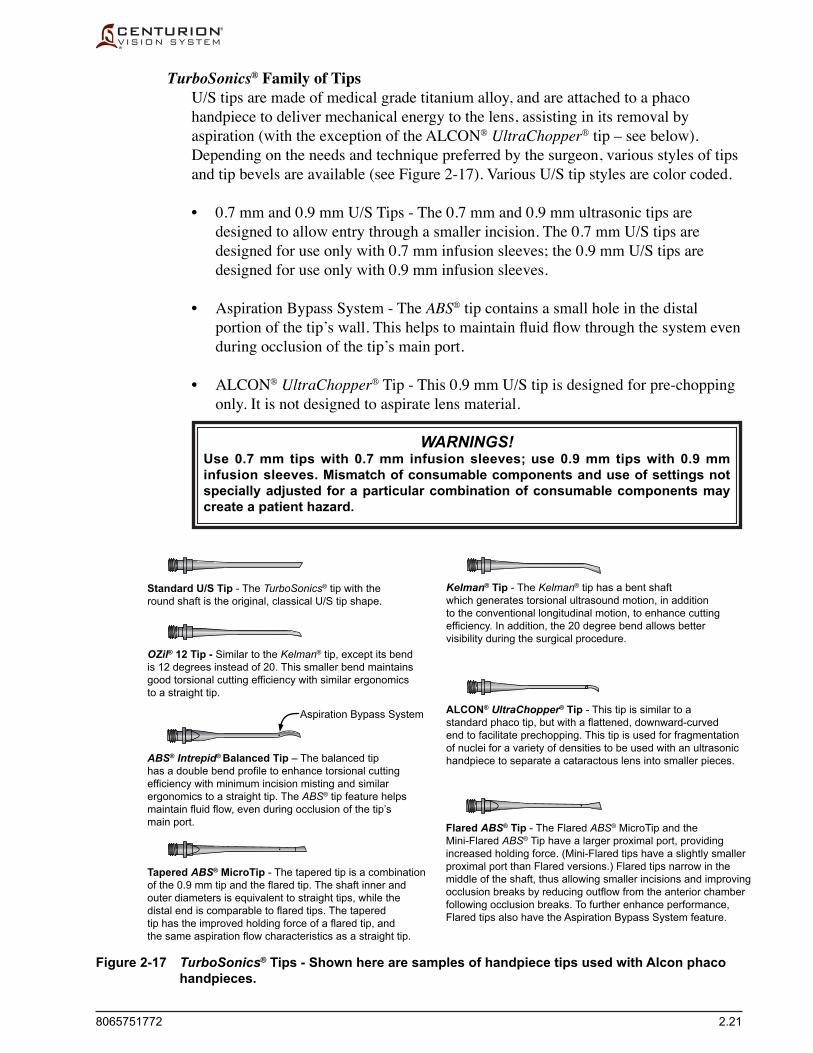
8065751772 2.21
Standard U/S Tip - The TurboSonics® tip with theround shaft is the original, classical U/S tip shape.
Kelman® Tip - The Kelman® tip has a bent shaftwhich generates torsional ultrasound motion, in additionto the conventional longitudinal motion, to enhance cuttingefficiency. In addition, the 20 degree bend allows bettervisibility during the surgical procedure.
Tapered ABS® MicroTip - The tapered tip is a combinationof the 0.9 mm tip and the flared tip. The shaft inner andouter diameters is equivalent to straight tips, while thedistal end is comparable to flared tips. The taperedtip has the improved holding force of a flared tip, andthe same aspiration flow characteristics as a straight tip.
ABS® Intrepid® Balanced Tip – The balanced tiphas a double bend profile to enhance torsional cuttingefficiency with minimum incision misting and similarergonomics to a straight tip. The ABS® tip feature helpsmaintain fluid flow, even during occlusion of the tip’smain port.
Aspiration Bypass System
Flared ABS® Tip - The Flared ABS® MicroTip and theMini-Flared ABS® Tip have a larger proximal port, providingincreased holding force. (Mini-Flared tips have a slightly smallerproximal port than Flared versions.) Flared tips narrow in themiddle of the shaft, thus allowing smaller incisions and improvingocclusion breaks by reducing outflow from the anterior chamberfollowing occlusion breaks. To further enhance performance,Flared tips also have the Aspiration Bypass System feature.
OZil® 12 Tip - Similar to the Kelman® tip, except its bendis 12 degrees instead of 20. This smaller bend maintainsgood torsional cutting efficiency with similar ergonomicsto a straight tip.
ALCON® UltraChopper® Tip - This tip is similar to astandard phaco tip, but with a flattened, downward-curvedend to facilitate prechopping. This tip is used for fragmentationof nuclei for a variety of densities to be used with an ultrasonichandpiece to separate a cataractous lens into smaller pieces.
TurboSonics® Family of Tips U/S tips are made of medical grade titanium alloy, and are attached to a phaco
handpiece to deliver mechanical energy to the lens, assisting in its removal by aspiration (with the exception of the ALCON® UltraChopper® tip – see below). Depending on the needs and technique preferred by the surgeon, various styles of tips and tip bevels are available (see Figure 2-17). Various U/S tip styles are color coded.
• 0.7mmand0.9mmU/STips-The0.7mmand0.9mmultrasonictipsaredesigned to allow entry through a smaller incision. The 0.7 mm U/S tips are designed for use only with 0.7 mm infusion sleeves; the 0.9 mm U/S tips are designed for use only with 0.9 mm infusion sleeves.
• Aspiration Bypass System - The ABS® tip contains a small hole in the distal portionofthetip’swall.Thishelpstomaintainfluidflowthroughthesystemevenduring occlusion of the tip’s main port.
• ALCON® UltraChopper® Tip - This 0.9 mm U/S tip is designed for pre-chopping only. It is not designed to aspirate lens material.
WARNINGS!Use 0.7 mm tips with 0.7 mm infusion sleeves; use 0.9 mm tips with 0.9 mm infusion sleeves. Mismatch of consumable components and use of settings not specially adjusted for a particular combination of consumable components may create a patient hazard.
Figure 2-17 TurboSonics® Tips - Shown here are samples of handpiece tips used with Alcon phaco handpieces.

2.22 8065751772
Infusion Sleeves Infusion sleevescoverthetipofthehandpiecetoprovideirrigatingfluidtothe
anterior chamber of the eye during surgery (see Figure 2-18). Infusion sleeves are used with phaco handpieces, and with the Ultraflow™* II I/A handpiece. Infusion sleevesmustbecorrectlymatchedtothespecifictiptype(seethefollowingdescriptions).
Depending on the needs and technique preferred by the surgeon, various styles of infusion sleeves are available.
Figure 2-18 CENTURION® OZil® Handpiece with Infusion Sleeve.
• StandardMicroSmooth® Infusion Sleeves - These are the original infusion sleeves. Standard infusion sleeves are 0.9 mm (purple), to be used with 0.9 mm tips.
• INTREPID® Ultra Infusion Sleeves - Ultra infusion sleeves have a smaller shaft diameter than original infusion sleeves. The smaller shaft diameter of the Ultra infusion sleeves is compatible with a 2.2 mm incision. Ultra infusion sleeves are available in 0.9 mm (rose) and 0.7 mm (yellow). Refer to consumable pack DFU for compatible tips.
• INTREPID® Nano Infusion Sleeves - Nano infusion sleeves have a smaller shaft taper and proximal outer diameter than Ultra infusion sleeves. The smaller proximal OD and decreased taper of the Nano sleeves are compatible with a smaller 1.8 mm incision. Nano infusion sleeves are available in 0.9 mm (orange) and 0.7 mm (gray). Refer to consumable pack DFU for compatible tips.
WARNINGS!
Use 0.7 mm tips exclusively with 0.7 mm infusion sleeves; use 0.9 mm U/S tips exclusively with 0.9 mm infusion sleeves. Mismatching U/S tips and infusion sleeves may create potentially hazardous fluidic imbalances.
Mismatch of consumable components and use of settings not specially adjusted for a particular combination of consumable components may create a patient hazard.
Read all packaging and Directions for Use supplied with the consumable packs prior to their use.
INFUSION SLEEVE
CENTURION

8065751772 2.23
Ultraflow™* II I/A Handpiece The Ultraflow™* II handpiece is used in I/A mode to maintain chamber pressure with
irrigation while removing cortical material via aspiration (see Figure 2-19). Refer to the Ultraflow™* II I/A Handpiece DFU for more information.
WARNINGS!
Use of non-ALCON® surgical reusable or disposable I/A handpieces that do not meet Alcon surgical specifications, or use of an Alcon handpiece not specified for use with the Centurion® Vision System, may result in a fluidic imbalance. This, in turn, may cause a shallowing or collapsing of the anterior chamber.
Exceeding the recommended level of 100 mmHg (133 hPa) with a 0.5 mm or larger I/A tip may cause anterior chamber shallowing and/or incarceration or tearing of the posterior capsule.
Perform visual inspection of accessories for burrs or bent tips prior to use.
I/A tips are not to be used with phaco handpieces.
Figure 2-19 ULTRAFLOW™* II HANDPIECE - Shown here is the Ultraflow® II hand-piece with I/A tip.
TM

2.24 8065751772
INTREPID® AutoSert® IOL Injector
The INTREPID® AutoSert® IOLInjectorisintendedtodeliverqualifiedAcrySof® intraocular lenses into the eye following cataract removal (see Figure 2-20). The IOL injector, after proper preparation with a loaded, single use cartridge, gives the surgeon footpedal control of AcrySof® lens insertion. The IOL injector supports the D/C cartridge or INTREPID® cartridge and associated lenses. Please refer to the INTREPID® AutoSert® IOLInjectorDFUforqualifiedcartridge/IOLcombinations.
The AutoSert® Injector step does not appear at the bottom of the surgery screen until it is added through the Custom/Procedure Builder dialog.
When connected, the Centurion® system begins calibrating the IOL injector, and if successful, it becomes ready for use, changing its icon in the adjustment bar from gray to green.
The IOL injector comes with a detachable and reusable plunger. Please refer to the INTREPID® AutoSert® IOL Injector DFU for instructions on proper preparation and use of the handpiece and plunger.
Figure 2-20 INTREPID® AutoSert® IOL INJECTOR - The AutoSert® Injector gives the surgeon footpedal control of IOL insertion (single use cartridge with lens not shown).
CAUTIONS•Do not ultrasonically clean the AutoSert® IOL Injector connector. Ultrasonic
cleaning of connector will cause irreparable damage.•Use care when handling AutoSert® IOL Injector, particularly when cleaning. Always
clean AutoSert® IOL Injector over a surface cushioned with a pad or rubber mat.•Be sure AutoSert® IOL Injector cable connector is dry before connecting it to console.•DonotimmerseAutoSert® IOLInjectorinanyfluidwhenplungerisnotretracted.•DonotdisconnectcableconnectorfromCenturion® system console until the
AutoSert® IOL Injector plunger is fully retracted.•Aspartofaproperlymaintainedsurgicalenvironment,itisrecommendedthat
a backup IOL injector be made available in the event the AutoSert® IOL injector handpiece does not perform as expected.
AutoSert® IOL Injector warnings are listed on next page

8065751772 2.25
WARNINGS!• The INTREPID® AutoSert® IOL Injector is non-sterile and must be cleaned and
sterilized prior to, and immediately after, each use.• Never immerse the IOL injector in liquid after autoclaving; allow it to air cool for at
least 15 minutes. Quenching could result in a potentially hazardous condition for the patient.
• The AutoSert® IOL Injector delivery system is for the implantation of Alcon qualified AcrySof® foldable IOLs. Unqualified lenses shall not be used with the system. See INTREPID® AutoSert® IOL Injector DFU or AcrySof® IOL DFU, or contact your Alcon representative, for qualified lens/cartridge combinations.
• The cartridge/IOL combination listed in the DFU, along with Alcon settings, has been validated per section 5 of BS EN ISO 11979-3:2006. Appropriate use of injector handpiece settings is important for successful IOL implantation. Inappropriate use of settings may lead to a potentially hazardous condition for the patient.
• Fully retract plunger before detaching nosecone from AutoSert® IOL Injector; otherwise, this could expose non-sterile portion of shaft and result in a potentially hazardous condition for the patient.
• For the intended IOL to be implanted, the proper Cartridge profile must be selected from the driving console, and the proper plunger must be attached to the AutoSert® IOL Injector. Failure to do so can result in a potentially hazardous condition for patient.
• The metal reusable plunger must be sterilized after each use. The reusable plunger is to be installed onto the handpiece or into the wrench prior to sterilization.
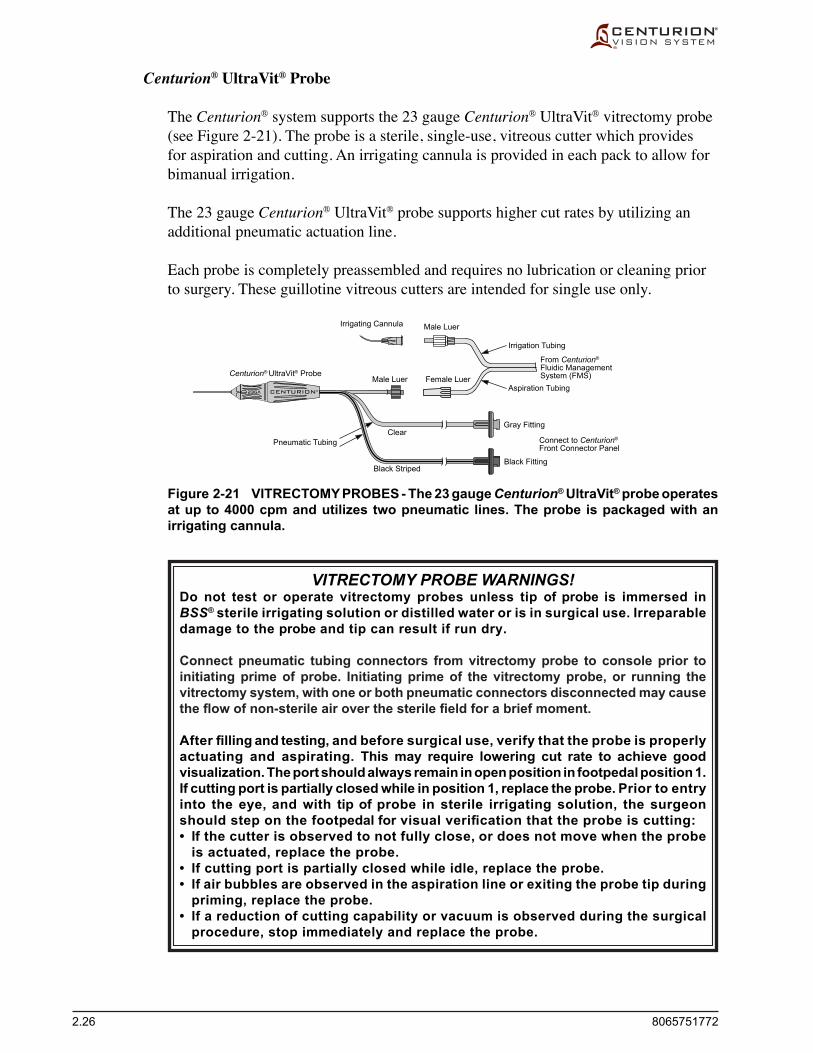
2.26 8065751772
Figure 2-21 VITRECTOMY PROBES - The 23 gauge Centurion® UltraVit® probe operates at up to 4000 cpm and utilizes two pneumatic lines. The probe is packaged with an irrigating cannula.
Centurion® UltraVit® Probe
The Centurion® system supports the 23 gauge Centurion® UltraVit® vitrectomy probe (see Figure 2-21). The probe is a sterile, single-use, vitreous cutter which provides for aspiration and cutting. An irrigating cannula is provided in each pack to allow for bimanual irrigation.
The 23 gauge Centurion® UltraVit® probe supports higher cut rates by utilizing an additional pneumatic actuation line.
Each probe is completely preassembled and requires no lubrication or cleaning prior to surgery. These guillotine vitreous cutters are intended for single use only.
VITRECTOMY PROBE WARNINGS!Do not test or operate vitrectomy probes unless tip of probe is immersed in BSS® sterile irrigating solution or distilled water or is in surgical use. Irreparable damage to the probe and tip can result if run dry.
Connect pneumatic tubing connectors from vitrectomy probe to console prior to initiating prime of probe. Initiating prime of the vitrectomy probe, or running the vitrectomy system, with one or both pneumatic connectors disconnected may cause the flow of non-sterile air over the sterile field for a brief moment.
After filling and testing, and before surgical use, verify that the probe is properly actuating and aspirating. This may require lowering cut rate to achieve good visualization. The port should always remain in open position in footpedal position 1. If cutting port is partially closed while in position 1, replace the probe. Prior to entry into the eye, and with tip of probe in sterile irrigating solution, the surgeon should step on the footpedal for visual verification that the probe is cutting:• If the cutter is observed to not fully close, or does not move when the probe
is actuated, replace the probe.• If cutting port is partially closed while idle, replace the probe.• If air bubbles are observed in the aspiration line or exiting the probe tip during
priming, replace the probe.• If a reduction of cutting capability or vacuum is observed during the surgical
procedure, stop immediately and replace the probe.
Male LuerIrrigating Cannula
Centurion® UltraVit® Probe
Irrigation Tubing
Pneumatic TubingClear
Black Striped
Aspiration Tubing
From Centurion®
Fluidic ManagementSystem (FMS)Female LuerMale Luer
Gray Fitting
Connect to Centurion®
Front Connector Panel
Black Fitting
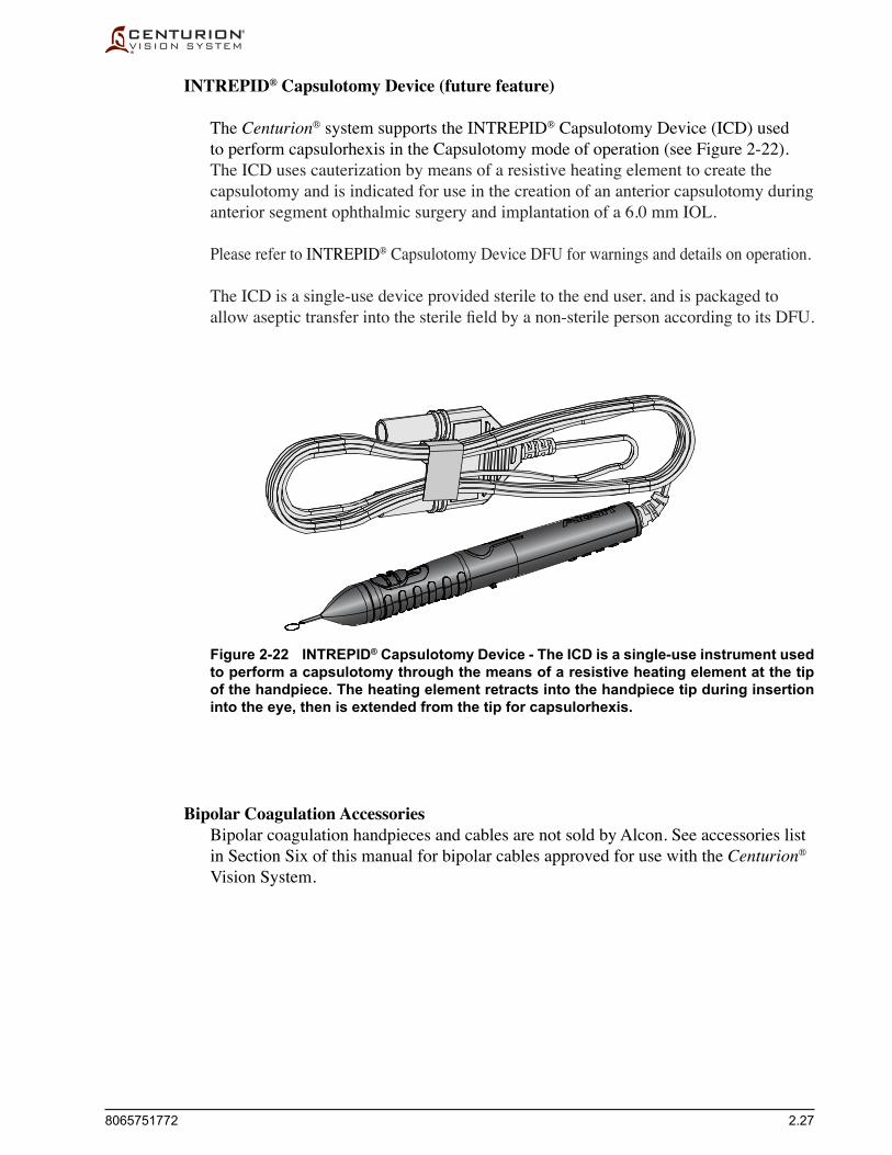
8065751772 2.27
INTREPID® Capsulotomy Device (future feature)
The Centurion® system supports the INTREPID® Capsulotomy Device (ICD) used to perform capsulorhexis in the Capsulotomy mode of operation (see Figure 2-22). The ICD uses cauterization by means of a resistive heating element to create the capsulotomy and is indicated for use in the creation of an anterior capsulotomy during anterior segment ophthalmic surgery and implantation of a 6.0 mm IOL.
Please refer to INTREPID® Capsulotomy Device DFU for warnings and details on operation.
The ICD is a single-use device provided sterile to the end user, and is packaged to allowaseptictransferintothesterilefieldbyanon-sterilepersonaccordingtoitsDFU.
Bipolar Coagulation Accessories Bipolar coagulation handpieces and cables are not sold by Alcon. See accessories list
in Section Six of this manual for bipolar cables approved for use with the Centurion® Vision System.
Figure 2-22 INTREPID® Capsulotomy Device - The ICD is a single-use instrument used to perform a capsulotomy through the means of a resistive heating element at the tip of the handpiece. The heating element retracts into the handpiece tip during insertion into the eye, then is extended from the tip for capsulorhexis.
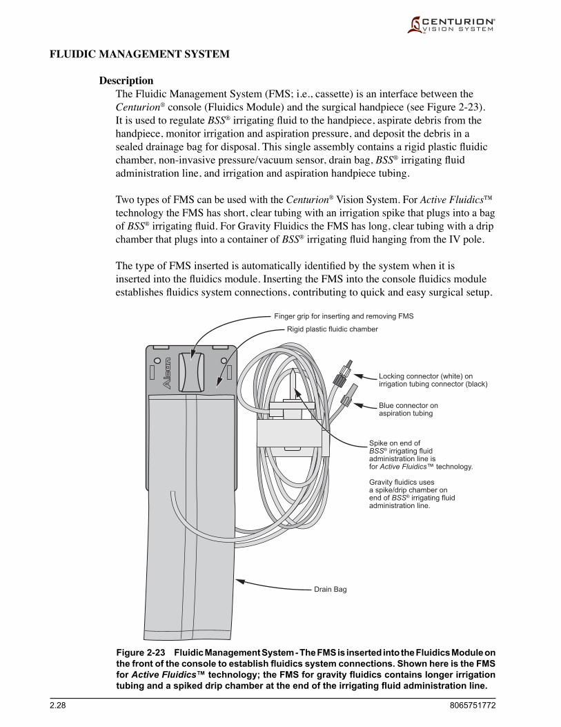
2.28 8065751772
FLUIDIC MANAGEMENT SYSTEM
Description The Fluidic Management System (FMS; i.e., cassette) is an interface between the
Centurion® console (Fluidics Module) and the surgical handpiece (see Figure 2-23). It is used to regulate BSS® irrigatingfluidtothehandpiece,aspiratedebrisfromthehandpiece, monitor irrigation and aspiration pressure, and deposit the debris in a sealeddrainagebagfordisposal.Thissingleassemblycontainsarigidplasticfluidicchamber, non-invasive pressure/vacuum sensor, drain bag, BSS®irrigatingfluidadministration line, and irrigation and aspiration handpiece tubing.
Two types of FMS can be used with the Centurion® Vision System. For Active Fluidics™ technology the FMS has short, clear tubing with an irrigation spike that plugs into a bag of BSS®irrigatingfluid.For Gravity Fluidics the FMS has long, clear tubing with a drip chamber that plugs into a container of BSS®irrigatingfluidhangingfromtheIVpole.
ThetypeofFMSinsertedisautomaticallyidentifiedbythesystemwhenitisinsertedintothefluidicsmodule.InsertingtheFMSintotheconsolefluidicsmoduleestablishesfluidicssystemconnections,contributingtoquickandeasysurgicalsetup.
Figure 2-23 Fluidic Management System - The FMS is inserted into the Fluidics Module on the front of the console to establish fluidics system connections. Shown here is the FMS for Active Fluidics™ technology; the FMS for gravity fluidics contains longer irrigation tubing and a spiked drip chamber at the end of the irrigating fluid administration line.
Blue connector onaspiration tubing
Spike on end ofBSS® irrigating fluidadministration line isfor Active Fluidics™ technology.
Gravity fluidics usesa spike/drip chamber onend of BSS® irrigating fluidadministration line.
Drain Bag
Locking connector (white) onirrigation tubing connector (black)
Finger grip for inserting and removing FMS
Rigid plastic fluidic chamber

8065751772 2.29
CONSUMABLE PACK CONFIGURATIONS
The family of Centurion®packsconsistofvariouscombinationsoffluidicmanagement systems (FMS), handpiece tips, infusion sleeves, and other components. Consumable items used with the Centurion® Vision System during surgery are designed to be used once and then discarded, unless labeled otherwise.
Please contact your Alcon Sales representative for complete up-to-date listings, and for in-service information prior to initial use of Alcon packs. All Centurion® packs contain Directions for Use (DFU). It is important to read and understand the DFU's prior to use.
In all cases, the instrument setup instructions contained in the manual should be thoroughlyunderstoodpriortousinganyofthepackconfigurations.
PRECAUTION: If an inconsistency exists between the instructions in the operator's manual and the Directions For Use (DFU) supplied with a consumable pack or accessory, follow the DFU.
Custom Pak™* Surgical Procedure Pack Configurations To better serve our customers we offer the opportunity for surgeons to specify a
Custom Pak™* surgical procedure pack for their own individual needs. Please contact your Alcon Sales representative for more information on how to design your own Custom Pak™* surgical procedure pack.
WARNINGS!
Mismatch of consumable components and use of settings not specially adjusted for a particular combination of consumable components may create a patient hazard.
Do not use packs that have exceeded the expiration date.
Sterile disposable medical devices should not be reused! These components have been designed for one time use only; do not reuse.
The equipment used in conjunction with the Alcon disposables constitutes a complete surgical system. Use of disposables other than Alcon disposables may affect system performance and create potential hazards, and if it is determined to have contributed to the malfunction of the equipment under contract, could result in the voidance of the contract and/or invoicing at prevailing hourly rates.

2.30 8065751772
Centurion® Fluidic Management System Packs Whenperformingaphacoemulsificationprocedure,one-of-twoCenturion® FMS packs
withhandpiecetipisused.OneFMSpackisspecificforActive Fluidics™ technology, (when using bag of BSS® irrigatingfluidinthebagbay)andtheotherisforgravityfluidics(whenusingcontainerofBSS®irrigatingfluidhangingfromIVpole).Thepackcan contain all the items listed below:
•Fluidic Management System (FMS) - This single assembly consists of a BSS® irrigatingfluidadministration line(tubingwithaspikeforActive Fluidics™ technology,orspike/dripchamberforgravityfluidics),irrigationtubing and aspiration tubing, a plastic body (containing pump, valves, and sensors), and a drainage bag (maximum capacity of 500 cc [500 mL]). Inserting the FMS into its console receptacle establishes the Centurion® fluidicsystem,allowingquickandeasysurgicalsetup.
•U/S Tip with Tip Holder/Wrench - The tip attaches to the ultrasonic handpiece. Securely tighten the tip with the all-in-one tip/wrench assembly, then remove the wrench from the tip. Several tip designs are available.
• InfusionSleeve-Thissingle-piecesiliconesleevefitsoverthehandpiecetiptoprovideirrigatingfluidintotheeye,protectiontothesurroundingtissues,andfluidicbalance.Twoinfusionsleevesareprovided;onetobeused with the phaco handpiece/tip, and a second to be used with the I/A handpiece/tip.
• TestChamber-Thetestchamberisasmallelastomericcapthatfitsoverthe handpiece tip to facilitate a functional irrigation and aspiration check of the handpiece and instrument prior to surgery.
• I/A Tip Wrench - A separate wrench is required to securely fasten the I/A tip to its handpiece, and also to remove the tip when the surgery is completed.
•Tray Support Cover - The tray support cover is a sterile plastic bag that is placed around the instrument tray and support arm. The cover is used to form a pouch in the tray to provide storage for the handpiece and tubing during surgery.
•Directions for Use (DFU) - Instructions for setup and removal of pack contents (not shown).
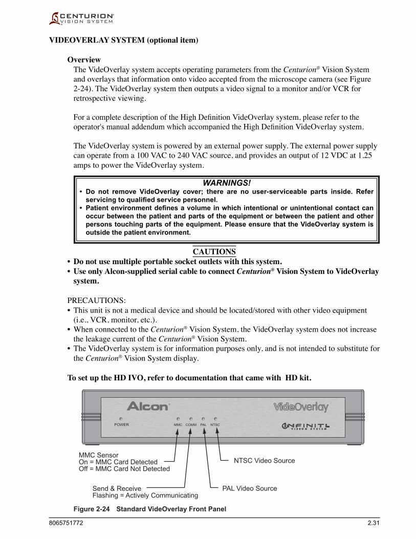
8065751772 2.31
VIDEOVERLAY SYSTEM (optional item)
Overview The VideOverlay system accepts operating parameters from the Centurion® Vision System
and overlays that information onto video accepted from the microscope camera (see Figure 2-24). The VideOverlay system then outputs a video signal to a monitor and/or VCR for retrospective viewing.
ForacompletedescriptionoftheHighDefinitionVideOverlay system, please refer to the operator'smanualaddendumwhichaccompaniedtheHighDefinitionVideOverlay system.
The VideOverlay system is powered by an external power supply. The external power supply can operate from a 100 VAC to 240 VAC source, and provides an output of 12 VDC at 1.25 amps to power the VideOverlay system.
WARNINGS!• Do not remove VideOverlay cover; there are no user-serviceable parts inside. Refer
servicing to qualified service personnel.• Patient environment defines a volume in which intentional or unintentional contact can
occur between the patient and parts of the equipment or between the patient and other persons touching parts of the equipment. Please ensure that the VideOverlay system is outside the patient environment.
CAUTIONS • Do not use multiple portable socket outlets with this system. • Use only Alcon-supplied serial cable to connect Centurion® Vision System to VideOverlay
system.
PRECAUTIONS: •This unit is not a medical device and should be located/stored with other video equipment
(i.e., VCR, monitor, etc.). •WhenconnectedtotheCenturion® Vision System, the VideOverlay system does not increase
the leakage current of the Centurion® Vision System. • TheVideOverlaysystemisforinformationpurposesonly,andisnotintendedtosubstitutefor
the Centurion® Vision System display.
To set up the HD IVO, refer to documentation that came with HD kit.
Figure 2-24 Standard VideOverlay Front Panel
POWER MMC COMM PAL NTSC
MMC SensorOn = MMC Card DetectedOff = MMC Card Not Detected
Send & ReceiveFlashing = Actively Communicating
PAL Video Source
NTSC Video Source

2.32 8065751772
Setup For Standard VideOverlay System
1. Ensure electric power to all systems is turned OFF. Attach the 12 V end of the external power supply to the VideOverlay system.
2. Attach the appropriate wall outlet adapter (USA, United Kingdom, Australia, or Europe) to the AC end of the external power supply, and plug it into an appropriate wall outlet (see Figure 2-26).
3. The VideOverlay system can operate using either Composite Video inputs/outputs or S-Videoinputs/outputs.AppropriatecablesshouldbeusedtoconfiguretheVideOverlaysystem. Connect the microscope camera output to the Composite or S-Video input of the VideOverlay system (see Figures 2-25 & 2-27).
PRECAUTION: If the microscope camera output has an RCA or BNC connector, connect the camera output to the VideOverlay Composite input. Do not use an adapter cable to connect the camera output to the VideOverlay S-Video input or loss of color will occur.
4. Connect the Composite or S-Video output of the VideOverlay system to a monitor or a VCR.Thevideooutputselectedmustbethesameconfigurationasthatusedforthevideoinput (Composite or S-Video).
5. With the video output connected to a monitor, turn the monitor and microscope camera power ON, and leave the VideOverlay system power OFF. If the video input and output cables are connected properly, the microscope camera image will appear on the monitor.
6. Connect the serial cable between the VideOverlay system and Centurion® Vision System.
7. Turn Centurion® Vision System power ON. Turn VideOverlay system power ON with its rear panel switch. The MMC light and either the PAL or NTSC Video source light should be illuminated (if not illuminated, check power supply connections).
8. With the Centurion® system touchscreen interface running, make sure the Send & Receive light blinks (if not blinking, check serial cable).
9. Observe the monitor video display. If the system does not operate correctly, contact an Alcon Technical Service representative.
COMPOSITEVIDEO
S-VIDEO
INFINITI™
IN OUT IN OUT
POWER
ON
OFF
12VDC1.25A
Figure 2-25 VideOverlay Rear Panel

8065751772 2.33
COMPOSITEVIDEO
S-VIDEO
INFINITI™ POWER
ON
OFF
12VDC1.25A
To Wall Outlet
Centurion® Vision System Rear Panel
ExternalPower Supply
Camera
Eye
Camera output to VideOverlay systeminput (S-Video or Composite Video)
Serial cable fromCenturion® Vision Systemto VideOverlay System
VCR outputto Monitor input
VideOverlay system output (Composite Video or S-Video)to VCR or Monitor input
VideOverlay Rear Panel
IN OUT IN OUT
Monitor
®
VCR
NOTE: On the VideOverlay system youmust use either Composite in/out orS-Video in/out. Do not use useC-in/S-out, or S-in/C-out.
Figure 2-26 Wall Outlet Adapters
USA, Japan, China
External Power Supply
United Kingdom Australia Europe
Figure 2-27 Standard VideOverlay Connection Diagram

2.34 8065751772
Figure 2-28 High Definition VideOverlay Connection Diagram
HD & SD COMPONENT
OUT
Y Cb CR
S-VIDEO CVBS
IN
USB
ANTENNA
6.0VDC2.1A ON
OFFRS232 PWRCONFIG
OUTIN
HD-SDISD-SDI
To Wall Outlet
ExternalPower Supply
HD Camerawith Component Video
Eye
Serial cable fromCenturion® Vision Systemto HD VideOverlay
HD VideOverlay
Sony PDW-70MD
Monitor
Centurion® Vision System Rear Panel
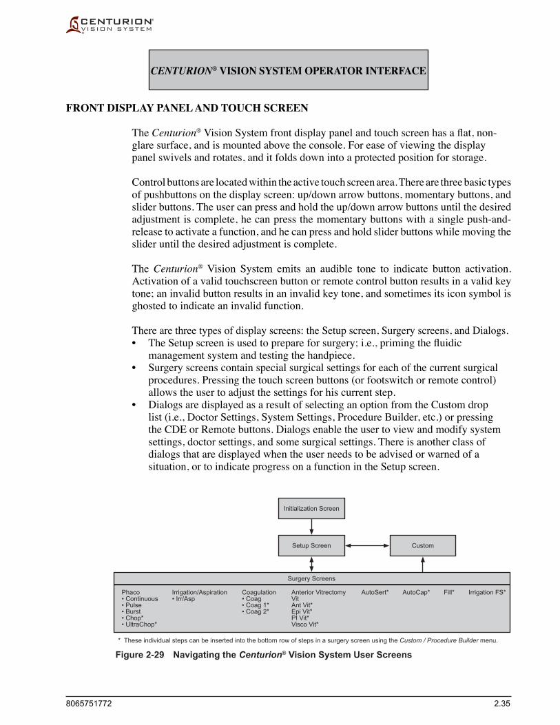
8065751772 2.35
CENTURION® VISION SYSTEM OPERATOR INTERFACE
FRONT DISPLAY PANEL AND TOUCH SCREEN
The Centurion® Vision System front display panel and touchscreenhasaflat,non-glare surface, and is mounted above the console. For ease of viewing the display panel swivels and rotates, and it folds down into a protected position for storage.
Control buttons are located within the active touch screen area. There are three basic types of pushbuttons on the display screen: up/down arrow buttons, momentary buttons, and slider buttons. The user can press and hold the up/down arrow buttons until the desired adjustment is complete, he can press the momentary buttons with a single push-and-release to activate a function, and he can press and hold slider buttons while moving the slider until the desired adjustment is complete.
The Centurion® Vision System emits an audible tone to indicate button activation. Activation of a valid touchscreen button or remote control button results in a valid key tone; an invalid button results in an invalid key tone, and sometimes its icon symbol is ghosted to indicate an invalid function.
There are three types of display screens: the Setup screen, Surgery screens, and Dialogs. • TheSetupscreenisusedtoprepareforsurgery;i.e.,primingthefluidic
management system and testing the handpiece. • Surgery screens contain special surgical settings for each of the current surgical
procedures. Pressing the touch screen buttons (or footswitch or remote control) allows the user to adjust the settings for his current step.
• Dialogs are displayed as a result of selecting an option from the Custom drop list (i.e., Doctor Settings, System Settings, Procedure Builder, etc.) or pressing the CDE or Remote buttons. Dialogs enable the user to view and modify system settings, doctor settings, and some surgical settings. There is another class of dialogs that are displayed when the user needs to be advised or warned of a situation, or to indicate progress on a function in the Setup screen.
Figure 2-29 Navigating the Centurion® Vision System User Screens
Initialization Screen
Setup Screen
Surgery Screens
* These individual steps can be inserted into the bottom row of steps in a surgery screen using the Custom / Procedure Builder menu.
Custom
Phaco Irrigation/Aspiration Coagulation Anterior Vitrectomy AutoSert* AutoCap* Fill* Irrigation FS* • Continuous • Irr/Asp • Coag Vit • Pulse • Coag 1* Ant Vit* • Burst • Coag 2* Epi Vit* • Chop* PI Vit* • UltraChop* Visco Vit*

2.36 8065751772
1.1 Doctor Name
2. Setup Status Window
3. Setup Steps
1. Status Panel
1.2 Procedure Type
1.4 Front Panel
1.6 Cumulative Dissipated Energy
1.7 SGS Pairing Indicator
1.3 Remote Control 1.5 Footswitch
SETUP SCREEN AND ITS FUNCTIONS
The Setup screen is displayed when one of the following occurs: • Thesystemispoweredupandinitializationissuccessful. • The screen is explicitly invoked by pressing the Setup button from a Surgery screen. • ACustomdialogscreenisexited. • TheFMSisremovedwhileinasurgeryscreenotherthanCoagulation. • Ahandpieceisselectedinasurgeryscreenandthehandpieceisnottuned. • AvalidFMSisinsertedwhiletheuserisinasurgeryscreen.
The Setup screen is divided into three sections. At the top is the Status Panel, below that is the Setup Status Window, and below that are the Setup Steps.
1. Status Panel The Status Panel (labeled 1 in Figure 2-30) consists of buttons and readouts that are
used to set up the system and then perform surgery. The Status Panel contains the same data in both the Setup screen and the Surgery screens, discussed later.
Figure 2-30 Functional Areas of the Setup Screen Using Active Fluidics™ technology

8065751772 2.37
1.1 Doctor Name Button The Doctor Name button in the Status Panel displays the currently-selected doctor.
Whenpressed,andalsowhensystemisfirstturnedon,thisbuttondisplaysadroplistofallthedoctorsenteredinthesystem(seeFigure2-31).Thefirstdoctoratthetopofthe list is the Alcon Settings doctor, which contains all the Alcon defaults. A summary of Alcon Settings defaults can be found in Table 1-7.
PRECAUTION: When the selected Doctor Name is Alcon Settings, changes to settings are temporary; although, when exiting Alcon Settings a dialog appears allowing the user to save the settings under a new doctor name.
At the bottom of the list is the Manage Doctors selection which allows the user to add a new doctor to the list, copy a doctor's settings to a new doctor name, rename a doctor, and delete a doctor from the list. The doctors are listed with the most-recently-selected doctor in the top position, immediately below Alcon Settings.
An asterisk is placed next to the doctor name if there are unsaved changes to surgical parameters. For Alcon Settings only, an asterisk appears if there are changes to doctor settings, but not if the only change is the addition or removal of steps.
WARNING!Ensure that appropriate Centurion® system parameters and system settings are selected prior to starting the procedure. Parameter and system settings include, but are not limited to, mode, power, vacuum, aspiration flow rate, etc.
Figure 2-31 Drop List of Doctors in System

2.38 8065751772
Manage Doctors… When Manage Doctors is selected from the Doctor Name drop list in the Status Panel
(see Figure 2-31), a dialog window appears with a window for the addition of new doctors (see Figure 2-32). Pressing the New Doctor button in the dialog prompts an alphanumeric keypad to appear upon which a new doctor name can be typed and acceptedbypressingtheConfirm() button (see Figure 2-33).
AdoctornamewithpreprogrammedsettingscanbeselectedandmodifiedfromtheManage Doctors dialog by pressing one of the following buttons (see Figure 2-34):
• Copy Doctor - An alphanumeric keypad appears where the settings used by the selected doctor can be copied to a new doctor name.
• Rename Doctor - An alphanumeric keypad appears where the selected doctor name can be changed.
• Delete Doctor - A dialog appears allowing the user to delete the selected doctor name and its settings.
Figure 2-32 Manage Doctors Dialog
Figure 2-33 Enter Doctor Name Keypad Dialog

8065751772 2.39
Figure 2-34 Manage Doctors Dialog
Figure 2-36 New Doctor Name Added to Drop List of Doctors
Figure 2-35 New Doctor Name
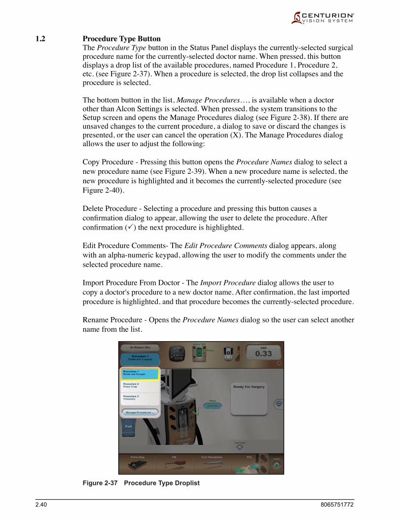
2.40 8065751772
1.2 Procedure Type Button The Procedure Type button in the Status Panel displays the currently-selected surgical
procedure name for the currently-selected doctor name. When pressed, this button displays a drop list of the available procedures, named Procedure 1, Procedure 2, etc. (see Figure 2-37). When a procedure is selected, the drop list collapses and the procedure is selected.
The bottom button in the list, Manage Procedures…, is available when a doctor other than Alcon Settings is selected. When pressed, the system transitions to the Setup screen and opens the Manage Procedures dialog (see Figure 2-38). If there are unsaved changes to the current procedure, a dialog to save or discard the changes is presented, or the user can cancel the operation (X). The Manage Procedures dialog allows the user to adjust the following:
Copy Procedure - Pressing this button opens the Procedure Names dialog to select a new procedure name (see Figure 2-39). When a new procedure name is selected, the new procedure is highlighted and it becomes the currently-selected procedure (see Figure 2-40).
Delete Procedure - Selecting a procedure and pressing this button causes a confirmationdialogtoappear,allowingtheusertodeletetheprocedure.Afterconfirmation() the next procedure is highlighted.
Edit Procedure Comments- The Edit Procedure Comments dialog appears, along with an alpha-numeric keypad, allowing the user to modify the comments under the selected procedure name.
Import Procedure From Doctor - The Import Procedure dialog allows the user to copyadoctor'sproceduretoanewdoctorname.Afterconfirmation,thelastimportedprocedure is highlighted, and that procedure becomes the currently-selected procedure.
Rename Procedure - Opens the Procedure Names dialog so the user can select another name from the list.
Figure 2-37 Procedure Type Droplist

8065751772 2.41
Figure 2-38 Manage Procedures Dialog
Figure 2-39 Procedure Names Dialog
Figure 2-40 Manage Procedures Dialog

2.42 8065751772
Table 2-3 Status of Handpiece Connectors
1.3 Remote Control Button Pressing the Remote Control button icon in the Status Panel displays the remote
control's six snap keys (A, B, C, D, E, and F) as an overlay on the current screen (white letters in center of black buttons, see Figure 2-41). This feature shows the user which buttons to press on the remote control to quickly navigate around the screen. Pressing the button again dismisses the overlay. The overlay is automatically dismissed after 60 seconds, upon a step change, or upon transition between the Setup Screen and Surgery Screen.
1.4 Front Panel Button The Front Panel Status icon button, at the top-center position in the Status Panel, is a
rendering of the front connector panel. If no FMS or handpiece is inserted, the front panel image is just shown as a ghosted outline of itself. If a FMS or handpiece is inserted, the Front Panel Status button becomes animated.
•The rectangular FMS icon is colored pink when unprimed, and it is green when primed. A label above the FMS icon indicates the type of FMS inserted into the fluidicsmodule(ActiveFMSorGravityFMSorCalibration),oritisblankifanFMS is not present. The label is red if FMS is not primed, and green when primed.
• Thethreehandpieceportsareplainwhennohandpieceisconnected,andcoloredwhen a handpiece is connected (see Table 2-3). The name of the connected handpiece (Phaco, PhacoT, UltraChop, UltraChopT, AutoSert®, AutoSertT, Not Used, Unknown, or blank if a handpiece is not present. AutoSert® not available in Infiniti® handpiece port 3) is printed to the right of its associated port. The handpiece name is printed red if the handpiece is not ready for use (not tested) and green when ready.
Figure 2-41 Remote Control Snap Navigation Buttons in Continuous Phaco Mode.
Port Color Name Color Indication Plain No name No handpiece Yellow Red Handpiece connected & selected, but not filled/tested Yellow Green Handpiece connected & selected, and is filled/tested Green Green Handpiece connected, not selected, and is filled/tested
Snap Button A
Snap Button D
Snap Button ESnap Button F
Snap Button C
Snap Button B

8065751772 2.43
1.5 Footswitch Button The Footswitch button icon depicts the type of footswitch connected to the Centurion®
Vision System (Centurion®, Centurion® Wired, or Constellation®). When button icon is pressed, the Custom/Doctor Settings/Footswitch tab dialog appears (see Figure 2-46).
The side switches on the footswitch button icon become animated, and the system emits a tone, when a switch is activated. Numbers on the footswitch's footpedal reflectthepositionofthefootpedal(0,1,2,3)asitisbeingdepressedandreleased.
The two paragraphs below apply to the Centurion® wireless footswitch, and do not apply to the Centurion® wired or Constellation® footswitches.
• AFootswitch Battery Status vertical bar, next to the Footswitch button, displays the wireless footswitch's battery charge with three cells. If the charge is low, one or two yellow cells are displayed; if charged, three green cells are displayed. The battery status bar is always displayed in the Setup screen. If the footswitch is not charging, and the battery charge is good, no icon is shown in the Surgery screen. If the footswitch is not charging, and the battery charge is low, the bar blinks slowly in both screens. If the footswitch is charging, the bar turns green with a lightning bolt in the middle, and is shown in both screens.
• Astairstepbar-graph,locatednexttotheFootswitch button, indicates the Footswitch Signal Strength. If the wireless signal strength is low it shows 1 red or 2 yellow bars; if signal strength is good it shows 3 to 5 green bars. If a wired footswitch is being used, nothing is displayed. The signal strength icon is always displayed in the Setup screen, but in the Surgery screen only when it is low.
1.6 Cumulative Dissipated Energy (CDE) The current CDE value is displayed on this button. The Metrics dialog appears when
the button is pressed (see Figure 2-42). Metrics for Ultrasonics and Fluidics are displayed for the current surgical procedure. Pressing the Cancel (X) button retains the metrics and returns the system to the last screen used. Pressing the Reset Metrics () button resets all metrics to zero and returns the system to the last screen used.
The CDE values are reached using the equations shown in Table 2-4.
1.7 SGS Pairing Indicator A ring of dots at the right end of the status panel indicates the status of the Surgical
Guidance System. A ring of dots indicates that the SGS is paired with the Centurion® system, while no ring of dots indicates that the SGS is not paired. Pairing is conducted in the Custom/System Settings/General window.
Centurion®
Centurion® Wired
Constellation®

2.44 8065751772
Figure 2-42 Metrics Dialog with Cumulative Dissipated Energy (CDE).
Total Case Time The timer starts (Case Begin) when first step is chosen and footpedal is depressed. The timer stops (Case Ended)
when the FMS and all active handpieces are removed. The timer pauses when system is placed in Set-up mode (Case is Inactive).
Ultrasonics U/S Total Time: Sum of Longitudinal Time and Torsional Time. Average Longitudinal Power: Average Longitudinal power over the time when Longitudinal power was applied.
For example, if Ultrasound Burst mode was selected and 100 mS burst pulses at 70% stroke were generated once a second, the Average Longitudinal Power would record 70%.
Average Longitudinal Power (FP3): Average Longitudinal power over the time when Longitudinal power was applied in footpedal position 3. This takes into account the U/S modulation aspects, resulting in a significantly lower reading than Average Longitudinal Power. For example, if Ultrasound Burst mode was selected and 100 mS burst pulses at 70% stroke were generated once a second, the Average Longitudinal Power in Position 3 would record 7%.
Total Longitudinal Power On Time: Total time Longitudinal power was active. This records the Longitudinal On-time, displayed in minutes and seconds.
Average Torsional Amplitude: Average torsional amplitude over the time when torsional power was applied. For example, if OZil® Burst mode was selected and 100 mS burst pulses at 70% amplitude were generated once a second, the Average torsional amplitude would record 70%.
Average Torsional Amplitude (FP3): Average torsional amplitude over the time when torsional power was applied in footpedal position 3. This takes into account the U/S modulation aspects, resulting in a significantly lower reading than Average Torsional Amplitude. For example, if Ultrasound Burst mode was selected and 100 mS burst pulses at 70% amplitude were generated once a second, the Average Torsional Amplitude in Position 3 would record 7%.
Total Torsional Amplitude On Time: Total time torsional power was active. This records the torsional On-time in minutes and seconds.
Equivalent Average Torsional Amplitude (FP3): Average U/S energy in footpedal position 3 calculated as:0.4 x Average Torsional Amplitude in Position 3.
Equivalent Average Ultrasonic Power (FP3): CDE U/S Total Time Cumulative Dissipated Energy (CDE): Total U/S energy in footpedal position 3 (both longitudinal and torsional)
calculated as:(Longitudinal Time x Average Longitudinal Power) + (Torsional Time x 0.4 x Average Torsional Amplitude)
The factor 0.4 represents approximate reduction of heat dissipated at incision as compared to conventional phaco.
Fluidics Total Aspiration Time: Total time the system was aspirating. Estimated Fluid Usage: An estimation of the volume of fluid aspirated based on system settings and time.
Table 2-4 CUMULATIVE DISSIPATED ENERGY (CDE) - CDE values are reached using formulas above.
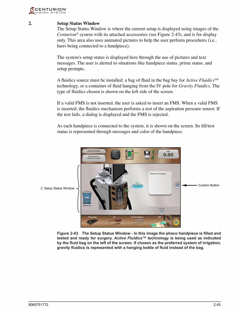
8065751772 2.45
2. Setup Status Window The Setup Status Window is where the current setup is displayed using images of the
Centurion® system with its attached accessories (see Figure 2-43), and is for display only. This area also uses animated pictures to help the user perform procedures (i.e., luers being connected to a handpiece).
The system's setup status is displayed here through the use of pictures and text messages. The user is alerted to situations like handpiece status, prime status, and setup prompts.
Afluidicssourcemustbeinstalled:abagoffluidinthebagbayfor Active Fluidics™ technology, or acontaineroffluidhangingfromtheIVpolefor Gravity Fluidics. The typeoffluidicschosenisshownontheleftsideofthescreen.
If a valid FMS is not inserted, the user is asked to insert an FMS. When a valid FMS isinserted,thefluidicsmechanismperformsatestoftheaspirationpressuresensor.Ifthe test fails, a dialog is displayed and the FMS is rejected.
Aseachhandpieceisconnectedtothesystem,itisshownonthescreen.Itsfill/teststatus is represented through messages and color of the handpiece.
Figure 2-43 The Setup Status Window - In this image the phaco handpiece is filled and tested and ready for surgery. Active Fluidics™ technology is being used as indicated by the fluid bag on the left of the screen. If chosen as the preferred system of irrigation, gravity fluidics is represented with a hanging bottle of fluid instead of the bag.
2. Setup Status WindowCustom Button

2.46 8065751772
Figure 2-44 Setup Screen with Custom Drop List Menu
Custom Button The Custom button, located half way up the right side of the Setup and Surgery
screens, enables the user to view and modify system settings, doctor settings, and some surgical settings. When the Custom button is pressed, a drop list menu appears with several available options (see Figure 2-44). When one of the options is selected from the menu, the respective dialog for that option is displayed and the drop list menu disappears. If no selection is made, the drop list menu disappears after about fiveseconds.
The following describes the purpose of each drop list menu item, the function of the controls in its dialog, and how the selections are invoked. The selections may be invoked whether the footswitch treadle and/or a footswitch button is depressed or not depressed, and the footswitch is functional when the dialog is displayed. The drop list menu items provide the user with options relating to viewing, copying, deleting, modifying, backing up, and restoring doctor/system settings.
• DoctorSettings • Save • SaveAs • SystemSettings • Backup/Restore • ProcedureBuilder • About • ViewEvents • ShutdownSystem
Custom Button

8065751772 2.47
2.1 Custom / Doctor Settings The Doctor Settings dialog is invoked when the user presses Doctor Settings on the
Custom drop list menu (see Figure 2-45). The Doctor Settings dialog enables the user to view and modify surgeon preferences for the currently-selected doctor. The firstscreentoappearcontainssettingsintheGeneral tab. Other tab settings are for Fluidics, Footswitch, Sounds, SGS, and Advanced.
EachdialoghasConfirm() and Cancel (X) buttons at the bottom of the screen. WhenConfirmisselected,allsettingschangedsincethedialogwasinvokedaresavedto persistent storage, the doctor dialog closes, and the settings take immediate effect. If the current doctor is the Alcon Settings default, the changes take immediate effect, but they are not saved to persistent storage; the changes are temporary. If Cancel is selected, the whole doctor dialog closes and the system returns to its prior settings.
Figure 2-45 Doctor Settings Dialog Screen - General Tab
Custom / Doctor Settings / General Tab • Default PEL (cm) - The (Patient Eye Level) adjustment is used to establish the
default PEL system offset for a particular surgeon. This is the value of PEL which will be used for the selected surgeon unless the value is changed through the Verify PEL function during system setup (see next description).
• Verify PEL (cm) - The Verify PEL button is used to automatically turn the Verify PEL dialog On or Off. When turned On, the Verify PEL dialog is automatically openedfollowingthehandpiecetest.UponcompletionofPELverification,theSurgery screen is automatically entered. When turned Off, the PEL step button at the bottom of the Setup screen must be manually pressed to open the Verify PEL dialog.
• Default Procedure - Press this button to display a list of procedures the doctor can select from to be his default procedure when beginning a case.
• Vit Setup - If the On button is selected, when entering the anterior vitrectomy mode a window appears to guide the user through the Vitrectomy Setup.

2.48 8065751772
Figure 2-46 Doctor Settings Dialog Screen - Fluidics Tab
Custom / Doctor Settings / Fluidics Tab • Continuous Irrigation Auto-Off Threshold - The Continuous Irrigation Auto-Off
feature is used to automatically turn continuous irrigation Off when the handpiece is removed from the eye. The threshold value ranges from 0 (Off) to 10 (Max). The threshold is used to customize the performance to the particular surgical environment such as tip/sleeve combination and height of instrument tray.
• Continuous Irrigation - Continuous Irrigation is applicable for lens removal, I/A, and vitrectomy surgical steps. When Continuous Irrigation is set to On (enabled), continuousirrigationwillbeactivefollowingthefirstfootpedaldepressionandthe continuous irrigation On tone is generated. When transitioning to another step of the same surgical type, continuous irrigation remains activated. When transitioning to a step that is a different surgical type, continuous irrigation is deactivated but then re-activated when the footpedal is depressed (except for Coagulation and AutoSert®).
• Reflux Offset (cmH2O [hPa])-RefluxpressureislimitedtoalevelequaltothecurrentinfusionpressureplusthevaluespecifiedfortheRefluxOffset,orthemaximum infusion pressure the system is capable of, whichever is less.
• Estimated Leakage Comp (cc/min [mL/min]) - Estimated Leakage Compensation adjusts for pressure losses due to incision leakage while the system is maintaining the programmed target IOP. Increasing this value is similar to adjusting the target IOP setting.

8065751772 2.49
Figure 2-47 Doctor Settings Dialog Screen - Footswitch Tab
• Irrigation Pressure Drop (%) - When the acquired value of the irrigation pressure sensorisbelowthevaluespecifiedbytheInfusionPressureDrop,thesystemwilldisplay an advisory dialog. When this setting is 100%, this feature is disabled.
• Vent Time Adjustment - This feature is used to adjust the degree of venting pressure at the handpiece tip that is adjusted in response to a vent (during transition from footpedal position 2 to position 1). There are three settings: Min, Medium,andMax.Minimumisthedefaultwhichprovidesunmodifiedventingperformance. Settings Mid and Max increase the net pressure experienced at the handpiece tip after a vent.
Custom / Doctor Settings / Footswitch Tab • Button Assignment - Pressing a button next to a switch activates a drop-down list
with functions that can be selected for that footswitch button. • Vit Cutter Button Dual Assignment - When in Anterior Vitrectomy mode of
operation, a selected footpedal button can be assigned the function of enabling and disabling the vitrectomy cutter function. This button, when in other modes, has a different assignment.
• Footswitch Range Spans (%) - The buttons on the screen allow you to adjust the treadle settings to your own personal preferences.
• Detent - The user can set the amount of Strength required to transition through the footpedal detents, and the footpedal Vibration feature can be turned On or Off.

2.50 8065751772
Custom / Doctor Settings / Sounds Tab The Sounds to Adjust dialog enables the surgeon to set a volume level for all tones
andvoiceconfirmations.Thevolume levels are set individually or all at the same time by pressing the Individual or All button at the top of the screen. When an individual button is selected, the volume level adjustment will pertain only to that selection. The tones and voices are adjusted with the Volume buttons located at the bottom of the screen. Each selection – except for Vacuum Level, Phaco Occlusion, Coagulation Power, and Low Bag Fluid Voice – may be turned Off so that no tone will be heard. Pressing the Play button emits a sample of the volume level selected.
Figure 2-48 Doctor Settings Dialog Screen - Sounds Tab
Custom / Doctor Settings / SGS Tab For details on the features associated with the optional Surgical Guidance System,
refer to your SGS operator's manual addendum.
Figure 2-49 Doctor Settings Dialog Screen - SGS Tab

8065751772 2.51
Custom / Doctor Settings / Advanced Tab • AutoSert® Full Extension Offset (mm) - When using a D/C cartridge, this feature is
used to adjust the full extension position at which the AutoSert® IOL injector stops moving forward. The adjustedpositionisdefinedinmillimetersrelativetothemaximum extension position. At the default setting (0) the AutoSert® IOL injector is at its maximum extension.
• AutoSert® Remote Default - When using a D/C cartridge, the Load Plunger and Preload IOL buttons are selected to set the default value of the remote control focus to be either Load Plunger or PreLoad IOL buttons.
• Irrigation Tone - Pressing the Irrigation Tone On or Off button determines whether or not the current doctor's preference is to hear a clicking sound as the footpedalisdepressedandfluidicsbeginflowing,andagainwhenthefootpedalisreleasedandfluidicsstop.
• CME Compliant Video Overlay - If the system is connected to a CME (Continuing Medical Education) Compliant Video Overlay, the On button should be selected; if not, select the Off button. This feature causes the Alcon logo to be displayed or not displayed on the VideOverlay.
Figure 2-50 Doctor Settings Dialog Screen - Advanced Tab

2.52 8065751772
Figure 2-51 Save As Dialog Screen
2.2 Custom / Save The Save dialog can be invoked when a change has been made to the current surgical
parameters and the user selects the Save option from the Custom drop list menu (see Figure 2-43). If there are no unsaved changes, or if no active surgery has taken place, the Save button is disabled.
The Save dialog provides the user with Save () and Cancel (X) buttons. If the Save Changes button is pressed, the changes are saved to the current doctor. If Cancel is selected, surgical parameters are not saved and the dialog closes.
The Alcon Settings doctor is the factory default and cannot be permanently changed, so the Save button is disabled when Alcon Settings is the current doctor.
2.3 Custom / Save As Pressing the Save As button (see Figure 2-43) opens the Enter Doctor Name dialog for
creation of a new doctor as a copy of the active doctor settings. A keyboard appears on the screen allowing the user to type a new doctor name. Adding a new doctor does not change the currently-selected doctor. If the maximum number of doctors has been reached,anotificationdialogappears.
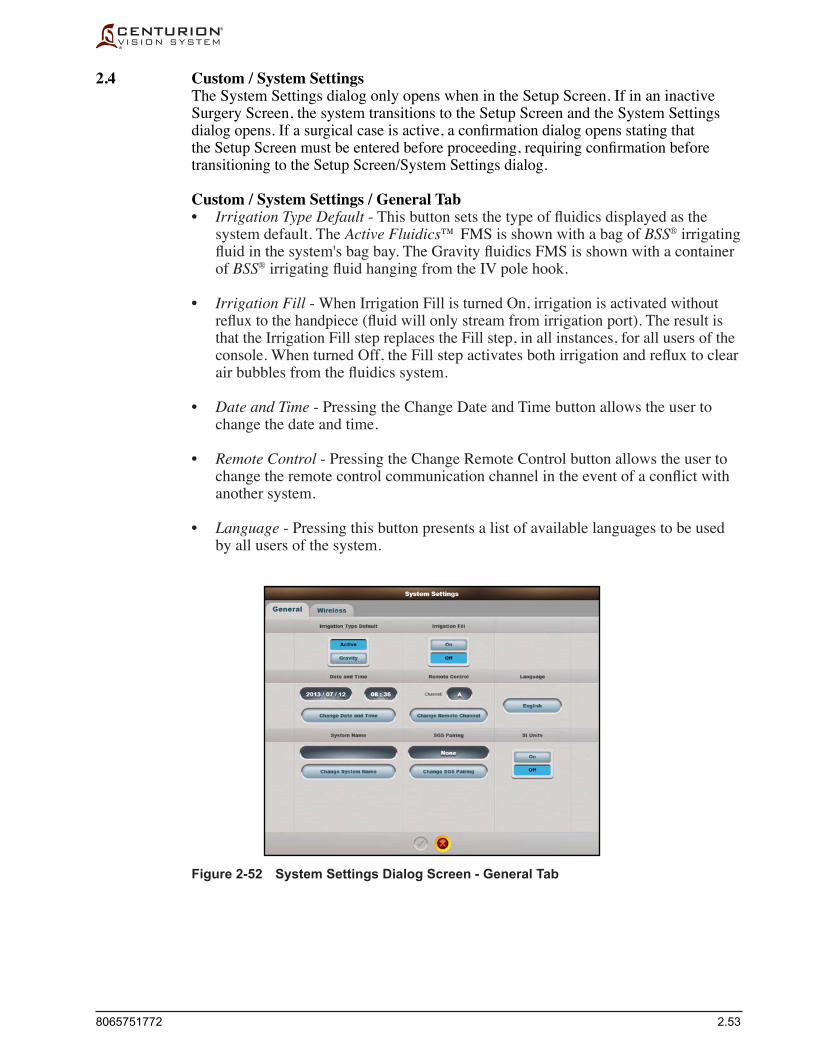
8065751772 2.53
Figure 2-52 System Settings Dialog Screen - General Tab
2.4 Custom / System Settings The System Settings dialog only opens when in the Setup Screen. If in an inactive
Surgery Screen, the system transitions to the Setup Screen and the System Settings dialogopens.Ifasurgicalcaseisactive,aconfirmationdialogopensstatingthattheSetupScreenmustbeenteredbeforeproceeding,requiringconfirmationbeforetransitioning to the Setup Screen/System Settings dialog.
Custom / System Settings / General Tab • Irrigation Type Default-Thisbuttonsetsthetypeoffluidicsdisplayedasthe
system default. The Active Fluidics™ FMS is shown with a bag of BSS® irrigating fluidinthesystem'sbagbay.TheGravityfluidicsFMSisshownwithacontainerof BSS®irrigatingfluidhangingfromtheIVpolehook.
• Irrigation Fill - When Irrigation Fill is turned On, irrigation is activated without refluxtothehandpiece(fluidwillonlystreamfromirrigationport). The result is that the Irrigation Fill step replaces the Fill step, in all instances, for all users of the console. WhenturnedOff,theFillstepactivatesbothirrigationandrefluxtoclearairbubblesfromthefluidicssystem.
• Date and Time - Pressing the Change Date and Time button allows the user to change the date and time.
• Remote Control - Pressing the Change Remote Control button allows the user to change the remotecontrolcommunicationchannelintheeventofaconflictwithanother system.
• Language - Pressing this button presents a list of available languages to be used by all users of the system.

2.54 8065751772
• System Name - Pressing the Change System Name button brings up a keyboard so theusercanchangethesystemnametofacilitateidentification.
• SGS Pairing - To change pairing of the Surgical Guidance System, press Change SGS Pairing to bring up its dialog. Press Find, and after the SGS device is located, the SGS ID number is displayed. Select the desired SGS device, then press the Pair button. The device ID number of the Paired SGS device will be displayed.
• SI Units - Display objects are converted to SI units when turned On. The unit labels and displayed values are converted as follows:
Default Units Label SI Units Label SI Value “mmHg” “hPa” hPa = mmHg * 1.33322 “cmH2O” “hPa” hPa = cmH2O * 0.980638 “cc/min” “mm3/sec” mm3/sec = cc/min * 16.667
Note that Equivalent Bottle Height is an alternate representation of the IOP surgical parameter. It is not itself a setting or actual value, and is never displayed in SI units.

8065751772 2.55
Custom / System Settings / Wireless Tab • Footswitch Network - This setting is used to turn the wireless footswitch network
on or off. When the wireless network is OFF, an icon appears in the status panel below the CDE display indicating that the wireless connection has been disabled.
• Footswitch Channel - Used to adjust the displayed channel value up or down, allowing user to select different frequency bands such that signal integrity can be maximized. For an indication of wireless channel integrity, a Green circle indicates high quality, yellow medium quality, amber low quality, and red indicates the signal is too weak to use. May be invisible for up to 10 seconds after Wireless tab is selected. If Footswitch Network setting is changed from Off to On, the Footswitch Channel Quality Status will not become visible until changes are saved.
• Footswitch Network Region - This feature establishes the appropriate network configurationfortheparticularregionoftheworld(Japan,NorthAmerica,World).Tochangethewirelesschannelforthefootswitch,thefootswitchmustfirstbecradled onto the back of the system. This "pairs" the footswitch with the system and allows the wireless channel to be changed. Note that since the wireless footswitch and the Surgical Guidance System (SGS) device share the same network, changing the wireless channel for the footswitch requires a re-pairing of the SGS device by depressing the Change SGS Pairing button under the General tab.
• Wi-Fi Network - These buttons turn the Wireless Footswitch/Surgical Guidance System wireless network On and Off. If it is desired to use the SGS or footswitch wirelessly, then the wireless network must be turned ON.
• Wi-Fi Channel-Setswirelesschannel.Changethissettingintheeventofaconflictwith another wireless device. See Footswitch Channel for wireless channel integrity.
• Wi-Fi Network Region - The Wi-Fi Network Region setting (Europe, Japan, North America) matches the system to its geographic location. This establishes the appropriatenetworkconfigurationfortheparticularregionoftheworld.
• Wi-Fi SSID - Shows Current Wi-Fi Network SSID system setting; this is the uniqueidentificationofthesystemontheWi-Finetwork.TheChangeSSIDbuttonisusedtomodifythesystemidentificationonthenetwork.
Figure 2-53 System Settings Dialog Screen - Wireless Tab

2.56 8065751772
Figure 2-54 Backup/Restore Dialog Screen - Backup Tab
2.5 Custom / Backup/Restore / Backup Tab This dialog contains a list of all doctors on the system, except Alcon Settings. When
a selected doctor name is highlighted, the Backup Doctor button is enabled. With USB removable media (flashdrive)insertedintotherearpanel'sUSBslot,pressingBackupDoctorcopiesthehighlighteddoctorfilefromtheconsoletotheflashdrive.With no doctor name highlighted, pressing the Backup All Doctors button copies the fullbackup(alldoctorfilesexceptAlconSettings)fromtheconsoletotheflashdrive.
Custom / Backup/Restore / Restore Tab WithUSBremovablemedia(flashdrive)insertedintotherearpanel'sUSBslot,this
dialog contains a list of all doctors on the removable media. When a selected doctor name is highlighted, the Restore Doctor button is enabled and can be pressed to copy thedoctorsettingstotheconsole.Withnodoctorshighlightedontheflashdrive,theRestore All Doctors button is enabled, allowing the system to perform a full backup fromthehighlighteddirectoryontheflashdrivetotheconsole.Ifadoctorfilealreadyexists,theResolveNameConflictdialogappearsandmustberesolved.
Figure 2-55 Backup/Restore Dialog Screen - Restore Tab
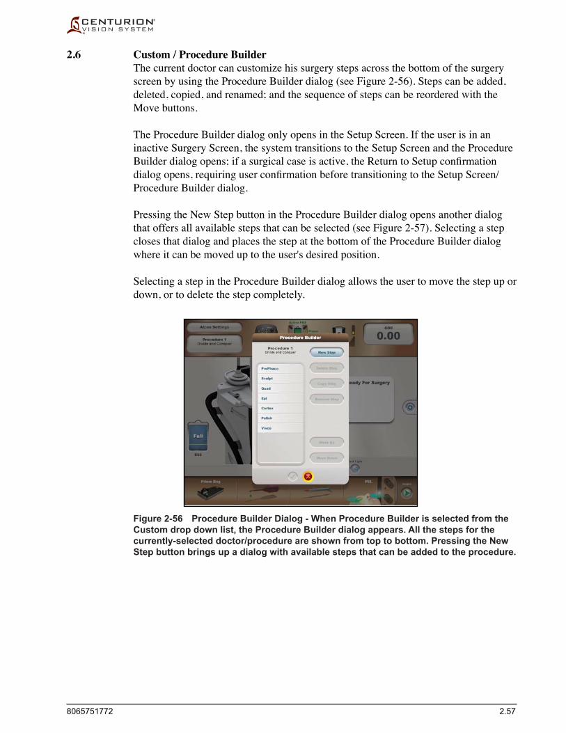
8065751772 2.57
2.6 Custom / Procedure Builder The current doctor can customize his surgery steps across the bottom of the surgery
screen by using the Procedure Builder dialog (see Figure 2-56). Steps can be added, deleted, copied, and renamed; and the sequence of steps can be reordered with the Move buttons.
The Procedure Builder dialog only opens in the Setup Screen. If the user is in an inactive Surgery Screen, the system transitions to the Setup Screen and the Procedure Builderdialogopens;ifasurgicalcaseisactive,theReturntoSetupconfirmationdialogopens,requiringuserconfirmationbeforetransitioningtotheSetupScreen/Procedure Builder dialog.
Pressing the New Step button in the Procedure Builder dialog opens another dialog that offers all available steps that can be selected (see Figure 2-57). Selecting a step closes that dialog and places the step at the bottom of the Procedure Builder dialog where it can be moved up to the user's desired position.
Selecting a step in the Procedure Builder dialog allows the user to move the step up or down, or to delete the step completely.
Figure 2-56 Procedure Builder Dialog - When Procedure Builder is selected from the Custom drop down list, the Procedure Builder dialog appears. All the steps for the currently-selected doctor/procedure are shown from top to bottom. Pressing the New Step button brings up a dialog with available steps that can be added to the procedure.

2.58 8065751772
Figure 2-57 Procedure Builder Dialog with Available Steps - Pressing the New Step button causes a dialog to appear with available steps that can be added to the selected doctor's procedure.
Figure 2-58 Procedure Builder Dialog with Fill Step Added - In this case the Fill step was selected from the right column of the Steps dialog (see prior figure). The Fill step appeared at the bottom of the existing steps, then the Move Up button was pressed to place the Fill step after the Epi step. More steps can be added, deleted, or moved prior to saving the action by pressing the Confirm () button.
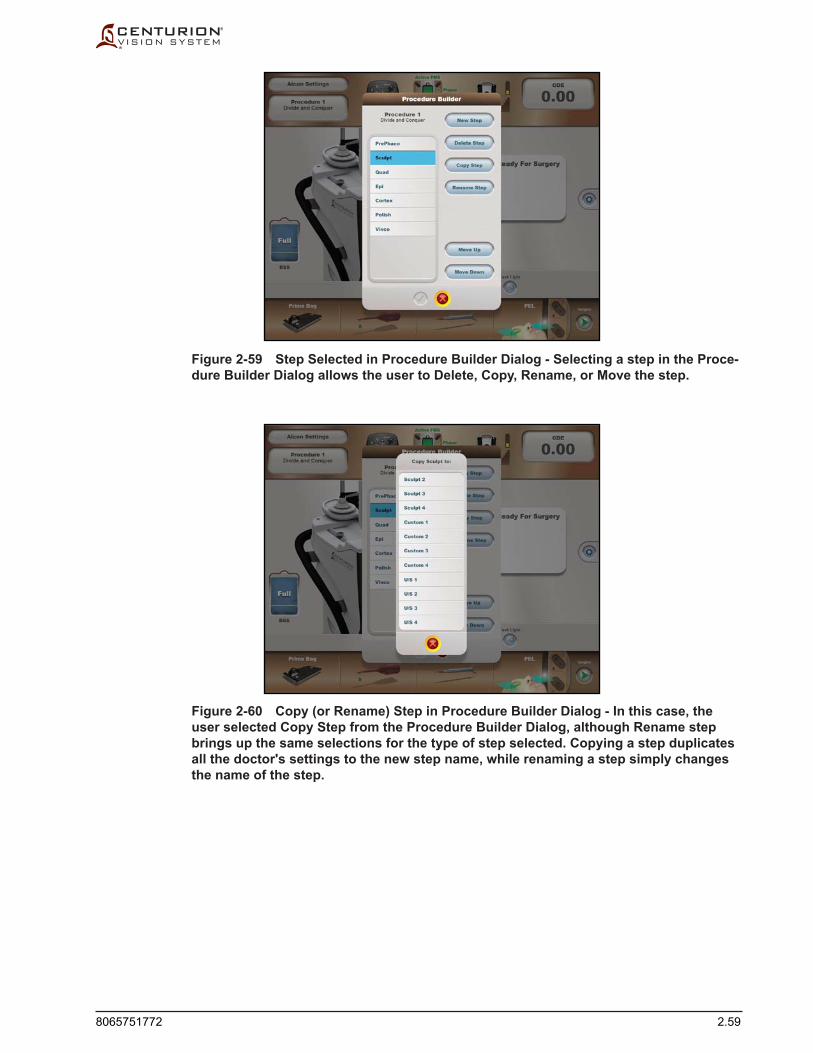
8065751772 2.59
Figure 2-59 Step Selected in Procedure Builder Dialog - Selecting a step in the Proce-dure Builder Dialog allows the user to Delete, Copy, Rename, or Move the step.
Figure 2-60 Copy (or Rename) Step in Procedure Builder Dialog - In this case, the user selected Copy Step from the Procedure Builder Dialog, although Rename step brings up the same selections for the type of step selected. Copying a step duplicates all the doctor's settings to the new step name, while renaming a step simply changes the name of the step.

2.60 8065751772
2.7 Custom / About For a quick reference to the Centurion® system'sconfiguration,open the Custom /
Aboutdialog.Itishereyouwillfindversions of Software, Hardware, and Logicware for system components (Host, I/A, Generator, MultiFunction, Footswitch) . Also shown are the versions of the Console and Footswitch Modems, and of the Footswitch Battery. Pressing the Patents button brings up a dialog of the Centurion® System's patent numbers. A phone number for technical assistance is printed at the bottom of the About dialog.
2.8 Custom / View Events This dialog contains information important to the service technician. The user can
select an Event in the upper dialog to read its Event Detail below.
Figure 2-61 The About Dialog - Upon installation by an Alcon service technician, a phone number for local technical assistance is programmed into the system and is displayed the bottom of the dialog (not shown in this image).
Figure 2-62 The Event Viewer Dialog.

8065751772 2.61
2.9 Custom / Shutdown System Pressing this button displays the Shutdownthesystem?confirmationdialog.If
canceled(X),thesystemwillnotshutdown.Ifconfirmed() the I/V pole lowers to its bottom position and the console shuts down.
Figure 2-63 The Shutdown System Dialog.
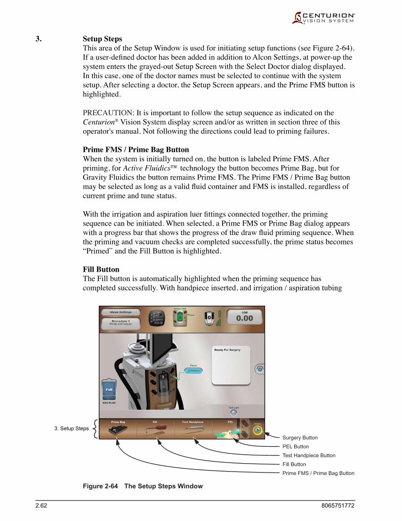
2.62 8065751772
3. Setup Steps
Surgery Button
PEL Button
Test Handpiece Button
Fill Button
Prime FMS / Prime Bag Button
3. Setup Steps This area of the Setup Window is used for initiating setup functions (see Figure 2-64).
Ifauser-defineddoctorhasbeenaddedinadditiontoAlconSettings,atpower-upthesystem enters the grayed-out Setup Screen with the Select Doctor dialog displayed. In this case, one of the doctor names must be selected to continue with the system setup. After selecting a doctor, the Setup Screen appears, and the Prime FMS button is highlighted.
PRECAUTION: It is important to follow the setup sequence as indicated on the Centurion® Vision System display screen and/or as written in section three of this operator's manual. Not following the directions could lead to priming failures.
Prime FMS / Prime Bag Button When the system is initially turned on, the button is labeled Prime FMS. After
priming, for Active Fluidics™ technology the button becomes Prime Bag, but for Gravity Fluidics the button remains Prime FMS. The Prime FMS / Prime Bag button maybeselectedaslongasavalidfluidcontainerandFMSisinstalled,regardlessofcurrent prime and tune status.
Withtheirrigationandaspirationluerfittingsconnectedtogether,theprimingsequence can be initiated. When selected, a Prime FMS or Prime Bag dialog appears withaprogressbarthatshowstheprogressofthedrawfluidprimingsequence.Whenthe priming and vacuum checks are completed successfully, the prime status becomes “Primed” and the Fill Button is highlighted.
Fill Button The Fill button is automatically highlighted when the priming sequence has
completed successfully. With handpiece inserted, and irrigation / aspiration tubing
Figure 2-64 The Setup Steps Window

8065751772 2.63
connectedtoit,pressingtheFillbuttonactivatesthefluidicssystemtofillthehandpiece.DuringthefillprocesstheFillHandpiecedialogappearsonthescreenwithaprogressbarthatshowstheprogressofthefillingsequence.Alsodisplayedinthe dialog is a Cancel button (X) and an Advance to Test Handpiece button.
OncethefillsequenceisinitiateditcanbeabortedbypressingtheCancel button (X), whereby the Fill Handpiece dialog closes and the Fill button darkens but remains highlighted. If Advance to Test Handpiece is pressed, the Fill dialog closes and the Test Handpiece function is selected.
Test Handpiece Button The Test Handpiece button may be selected only when the FMS is primed and a
phaco handpiece is connected.
The Centurion® Vision System allows a CENTURION® OZil® handpiece and INFINITI® OZil® handpiece to be connected at the same time, but the user must perform the Test Handpiece sequence for each handpiece. Pressing the Swap Phaco / UltraChop button switches handpieces for the testing sequence.
When the Test Handpiece button is selected the test handpiece dialog will display progressoftheflowcheckandvacuumcheck.ACancelbuttonalsoappears.Oncethetest sequence is initiated, it can be aborted by the user by pressing the Cancel button (X) or removing the FMS, or it can be left to proceed to completion.
PEL Button By default, the Verify PEL (cm) dialog appears upon successful completion of the
handpiece test sequence. This can be changed to a manual step by entering the Custom/Doctor Settings/General dialog and pressing the Verify PEL Off button.
Test ICD Button The Test ICD button may be selected only when a single-use INTREPID®
Capsulotomy Device (ICD) handpiece has been connected, and the current doctor has added the Capsulotomy step through the Custom / Procedure Builder feature. The color of the ICD image indicates its ready state: red for not ready (not tested or failed test), or green for ready (successfully tested).
When connected, the Test ICD button replaces the Test Handpiece button used with the phaco handpiece. The Test ICD button must be pressed to prepare it for a capsulotomy.
The ICD must be enabled upon entering the Capsulotomy step, but if the ICD has not yet been tested, the user will be asked to go back to the Setup screen for testing. Pressing the Enable button in the Capsulotomy step screen is the last preparatory step prior to performing the capsulotomy. Inthisstep,theRefluxswitchcanalsobeusedtoenable the the ICD.
Surgery Button If the Surgery button is pressed the system goes to the appropriate Surgery Screen as
determinedbytheprocedureselected.Thefirstsurgerystepforthedoctor’sprocedureis entered.

2.64 8065751772
Figure 2-65 The Centurion® Vision System Surgery Screen - This screen is for phaco modes of operation. The screens for other modes of operation look similar to this, but may have more or fewer oval display buttons and surgical parameters corresponding to the surgery step.
SURGERY SCREEN AND ITS FUNCTIONS
The Surgery Screen contains the buttons, readouts, and controls that allow the user to perform surgical functions. This screen is displayed when one of the following occurs:
• TheSurgerybuttonispressedfromtheSetupScreen. • ThehandpieceandprimingfunctionsarecompletedintheSetupScreenandno
other connected handpieces are “Not Tuned.”
The Surgery Screen is divided into three sections (see Figure 2-65). At the top is the Status Panel, below that is the Surgery Window, and below that is a row of Surgery Steps.
Depending on the procedure type and surgery step selected, the Surgery Screen contains tools and surgical parameters corresponding to the selections. Although several representative surgery screens are shown in this section of the manual, not all screens showing handpiece/procedure/steps are shown.
1. Status Panel The buttons in the surgery Status Panel are the same as the buttons in the setup Status
Panel (see Setup Screen earlier in this section of the manual for descriptions).
2. Surgery Window The Surgery Window occupies the center of the Surgery Screen and is broken into
upper and lower halves. The top half has the surgery controls, and the lower half has the fluidics controls, both of which are described on the following pages.
The actual values for certain parameters are shown in oval display buttons. With the exception of the Vacuum parameter, the upper limit for each setting represents
2. Surgery Window
3. Surgery Steps
1. Status Panel(descriptions are the same
as in the Setup Screen)

8065751772 2.65
its maximum setting. (For the Vacuum limit setting, if the vacuum limit is set to 700+mmHg[933+hPa],thentheupperlimitdoesnotexist.)
Each surgery step has operating parameter settings that are established by default. During surgery the user may change the parameters in any of the steps. Any parameter changes made may be explicitly saved by the user using the Save As option (if Alcon Settings is doctor) or the Save option (if other than Alcon Settings is doctor) from the Custom drop list. Also, if there are unsaved changes to the surgery steps and the user changes the doctor or lens removal procedure, a dialog box appears asking the user to save or discard any unsaved changes. Powering down the system automatically dismisses any unsaved changes.
2.1 Surgery Controls For Phaco steps, Coag steps, Vitrectomy steps, Coagulation steps, and AutoSert®
injector steps, the upper half of the Surgery Window contains the surgery controls (see Figure 2-66). The surgery controls available are dependent on the type of step selected.
Mode Button The Mode button in the top-center of the Surgery Controls area displays the current
mode for the step; in Figure 2-66 it is Continuous mode in the PrePhaco step. The Phaco and Anterior Vitrectomy modes can be changed by pressing the top-center Mode button and selecting another from a drop list. Depending on the current step, the Alcon Settings mode selections are:
Phaco Irrigation/Aspiration AutoSert® Coagulation Anterior Vitrectomy • Continuous • Irr / Asp • AutoSert® • Coagulation • Anterior Vit • Pulse • Epi Removal • Burst • I/A Cut • Peripheral Irid • Visco Asp
Figure 2-66 Surgery Control Window with Phaco Surgery Controls Identified - This upper half of the Surgery Control Window is used to observe current surgical performance levels, and to adjust surgery settings by pressing the oval display buttons and buttons to present control dialogs.
2.1 Surgery Controls
Mode Button IP (Intelligent Phaco) Button
Custom Button
Task Light Button
Oval Display Buttons
Status Panel
Fluidics Controls
Surgery Steps

2.66 8065751772
Oval Display Buttons Oval display buttons (see Figure 2-66) show parameter settings for a procedure in
its current step. Pressing an Oval Display Button brings up a dialog where the user can change settings for each footpedal position within a step (see Figure 2-67). This dialogincludesbuttonstotogglebetweenlinear(/)orfixed(–)footpedalcontrol,upand down buttons to adjust setting values in small increments, and slide buttons to quickly adjust setting values in large increments.
Figure 2-67 Oval Display Button Dialog - Oval display buttons on a surgical screen show parameter settings for a current step (see Figure 2-66). Pressing an oval display button brings up a dialog where the user can make adjustments to the settings according to doctor's preferences.
Press this button to toggle between linear (/) orfixed (–) footpedal control of surgical parameters
This oval display window is a visual representation oftorsional amplitude from left to right through footpedal position 3.
Up and Down buttons are used tomake incremental adjustments totorsional amplitude.
For torsional amplitude, 0% is the settingwhen footpedal enters position 3, and 20%is the upper limit setting when footpedalis fully depressed.
Slide button is used to quicklymake large adjustments totorsional amplitude.
This adjustment dialog is forfootpedal position 3
Task Light Button This button is pressed to turn the front panel task light on and off. When turned on the
icon in the Task Light button shows light rays; when turned off the light rays are muted.
Custom Button Pressing this button presents a list of features that can be selected, allowing the user
to adjust system settings to the surgeon's preferences. This feature is discussed at length earlier in this section of the operator's manual.
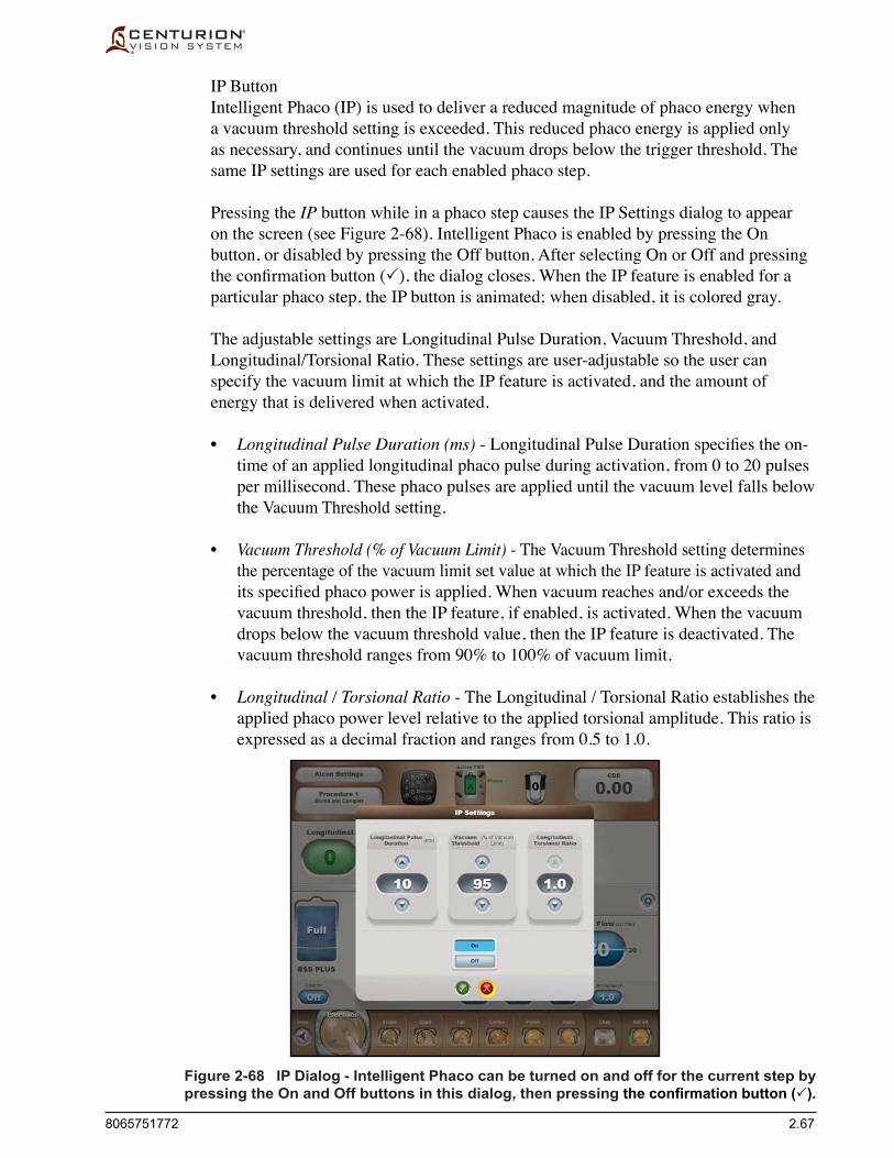
8065751772 2.67
Figure 2-68 IP Dialog - Intelligent Phaco can be turned on and off for the current step by pressing the On and Off buttons in this dialog, then pressing the confirmation button ().
IP Button Intelligent Phaco (IP) is used to deliver a reduced magnitude of phaco energy when
a vacuum threshold setting is exceeded. This reduced phaco energy is applied only as necessary, and continues until the vacuum drops below the trigger threshold. The same IP settings are used for each enabled phaco step.
Pressing the IP button while in a phaco step causes the IP Settings dialog to appear on the screen (see Figure 2-68). Intelligent Phaco is enabled by pressing the On button, or disabled by pressing the Off button. After selecting On or Off and pressing theconfirmationbutton(), the dialog closes. When the IP feature is enabled for a particular phaco step, the IP button is animated; when disabled, it is colored gray.
The adjustable settings are Longitudinal Pulse Duration, Vacuum Threshold, and Longitudinal/Torsional Ratio. These settings are user-adjustable so the user can specify the vacuum limit at which the IP feature is activated, and the amount of energy that is delivered when activated.
• Longitudinal Pulse Duration (ms)-LongitudinalPulseDurationspecifiestheon-time of an applied longitudinal phaco pulse during activation, from 0 to 20 pulses per millisecond. These phaco pulses are applied until the vacuum level falls below the Vacuum Threshold setting.
• Vacuum Threshold (% of Vacuum Limit) - The Vacuum Threshold setting determines the percentage of the vacuum limit set value at which the IP feature is activated and itsspecifiedphacopowerisapplied.Whenvacuumreachesand/orexceedsthevacuum threshold, then the IP feature, if enabled, is activated. When the vacuum drops below the vacuum threshold value, then the IP feature is deactivated. The vacuum threshold ranges from 90% to 100% of vacuum limit.
• Longitudinal / Torsional Ratio - The Longitudinal / Torsional Ratio establishes the applied phaco power level relative to the applied torsional amplitude. This ratio is expressed as a decimal fraction and ranges from 0.5 to 1.0.

2.68 8065751772
2.2 Fluidics Controls The lower half of the Surgery Window contains the Fluidics Controls (see Figures
2-69 and 2-70). These parameters always involve irrigation, vacuum, and aspiration controls, and are independent of the Surgery Controls. Fluidics Controls are available in all steps but AutoSert® and Coagulation.
Fluidics Administration The Centurion®Visionsystemsupportstwotypesoffluidicsadministrationtodeliver
andcontrolfluidpressure:Active Fluidics™ technology is an automated system that administersfluidfromabagofBSS®irrigatingfluidwithinitsbagbay(seeFigure2-69), and Gravity FluidicsisusedforfluidadministrationusingthepowerIVpole(see Figure 2-70).
IOP Control (used with Active Fluidics™ technology) When the Active Fluidics™ FMS is used, IOP (IntraOcular Pressure) control
functionality becomes enabled. Active Fluidics™ technology allows control and maintenance of intraocular pressure under the varying conditions experienced during surgery.Figures2-71(fixed)and2-72(linear)depictthesurgeryscreenwithActive Fluidics™ technology in use. The vertical lines within the oval display button depict the separation of footpedal positions.
IOP Fluid Bag (used with Active Fluidics™ technology) TheIOPfluidbag“fuelgauge”providesanestimatedvalueofremainingBSS®
irrigatingfluidwithintheirrigationbagwhenusingtheActive Fluidics™ FMS. As the procedure progresses the indicated value ranges from full (>500 ml) to empty (0 ml). If the volume drops to below 100 ml, the bag color changes from blue to red. An advisory is issued when the usable bag volume drops to 0 ml.
IOP Settings (used with Active Fluidics™ technology) Pressing the IOP oval display button brings up the IOP Setpoints dialog (see Figures
2-71 & 2-72). This dialog allows for tailoring of IOP level as a function of footswitch position. The vertical separation lines indicate the transition point between footswitch positions.ThedialoginFigure2-72showsthatlinear/fixedbuttonshavebeenpressedtoactivatefixedfootpedalcontrolinposition1,andlinearfootpedalcontrolin footpedal positions 2 and 3. The Up/Down buttons, or the Slide button, have been used to adjust new IOP settings.
IV Pole Settings (used with gravityfluidics) When the Gravity Fluidics FMS is used, traditional gravity-fed irrigation pressure is
provided from a container of BSS®irrigatingfluidhungfromahookonthemotorizedIV pole (see Figure 2-70). Irrigation pressure is increased or decreased by raising or lowering the IV pole.
Usinggravityfluidics,raisingtheIVpoletoitsmaximumheightof150cmresultsin maximum irrigation pressure (150 cm includes a 110 cm maximum vertical height above the pressure sensor plus a maximum PEL of -40 cm). In the event of power loss, bottle position is maintained; however, if the unit is turned off using the Standby switch, the IV pole automatically retracts to its storage position.
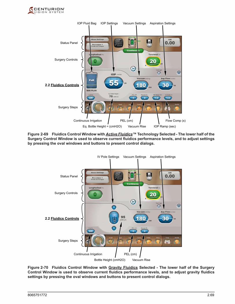
8065751772 2.69
Figure 2-69 Fluidics Control Window with Active Fluidics™ Technology Selected - The lower half of the Surgery Control Window is used to observe current fluidics performance levels, and to adjust settings by pressing the oval windows and buttons to present control dialogs.
Figure 2-70 Fluidics Control Window with Gravity Fluidics Selected - The lower half of the Surgery Control Window is used to observe current fluidics performance levels, and to adjust gravity fluidics settings by pressing the oval windows and buttons to present control dialogs.
IOP Fluid Bag
Continuous Irrigation
IOP Settings Vacuum Settings Aspiration Settings
PEL (cm) Flow Comp (x)
Vacuum Rise IOP Ramp (sec)Eq. Bottle Height = (cmH2O)
2.2 Fluidics Controls
Surgery Controls
Status Panel
Surgery Steps
Continuous Irrigation
IV Pole Settings Vacuum Settings Aspiration Settings
PEL (cm)
Vacuum RiseBottle Height (cmH2O)
2.2 Fluidics Controls
Surgery Controls
Status Panel
Surgery Steps
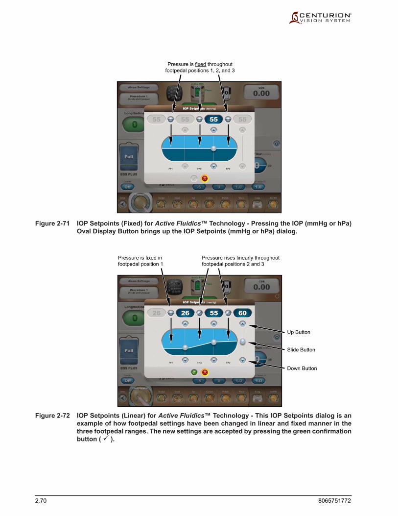
2.70 8065751772
Figure 2-72 IOP Setpoints (Linear) for Active Fluidics™ Technology - This IOP Setpoints dialog is an example of how footpedal settings have been changed in linear and fixed manner in the three footpedal ranges. The new settings are accepted by pressing the green confirmation button ( ).
Figure 2-71 IOP Setpoints (Fixed) for Active Fluidics™ Technology - Pressing the IOP (mmHg or hPa) Oval Display Button brings up the IOP Setpoints (mmHg or hPa) dialog.
Pressure is fixed throughoutfootpedal positions 1, 2, and 3
Pressure is fixed infootpedal position 1
Pressure rises linearly throughoutfootpedal positions 2 and 3
Slide Button
Down Button
Up Button

8065751772 2.71
Vacuum Settings The operator can adjust the vacuum limit (Vacuum / mmHg) using the front display
panelortheremotecontrol.Theadjustablevacuumlimitrangeis0to700+mmHg(0to933+hPa),where700+mmHg(933+hPa)islimitedbyatmosphericpressure.
Aspiration Settings The operator can adjust the aspiration limit (Asp Flow / cc/min) using the front
display panel or the remote control. The adjustable aspiration limit range is 12 to 60 cc/min (12 to 60 mL/min).
Continuous Irrigation Continuous Irrigation (Cont Irr) is available in most surgical steps (except
Capsulotomy, AutoSert®, Coag) and allows for irrigation of the eye during surgery by opening the irrigation valve, regardless of footswitch position. The Continuous Irrigation mode default setting can be set to On or Off through the Custom / Doctor Settings / Fluidics tab.
When Continuous Irrigation is enabled, footpedal range 1 is eliminated, thereby expanding the range of footpedal position 2. Continuous Irrigation remains enabled until transitioning to another step where Continuous Irrigation is disabled (irrigation valve off). Continuous Irrigation may also be automatically turned off when the tip is removed from the eye as determined by the Continuous Irrigation Auto-Off Threshold setting (Custom / Doctor Settings / Fluidics tab).
Continuous Irrigation can be turned On and Off by doing the following: - Press the Cont Irr button on the surgery screen. - Use the remote control's Parameter Selection keys to select the Cont Irr button, then
pressthe+or-keyontheremotecontrol. - Program a footswitch switch for the Continuous Irrigation function, then press the
designated switch on the footswitch.
PRECAUTION: Before switching handpieces it is advised to exit the eye, then turn Continuous Irrigation off to close the irrigation valve and prevent excess BSS® sterile irrigatingsolutionfromflowingoutofthehandpiece.
Eq. Bottle Height = (cmH2O) (used with Active Fluidics™ technology) Equivalent Bottle Height is calculated when using Active Fluidics™ technology
topresentthecomparativebottleheightiftheIVpolewasusedforfluidicadministration. The equivalent IV pole height is calculated from the value in the IOP oval display button (1 mmHg = 1.36 cmH20 = 1.33 hPa).
Bottle Height (cm) (used with gravityfluidics) This readout shows the irrigation pressure at the selected IV pole height.
PEL (cm) The PEL button allows adjustment of the Patient Eye Level setting from the surgery
screen. (For details on setting the PEL, see the Setup Screen description.)

2.72 8065751772
Vacuum Rise At the onset of an occlusion, it may be desired to slow down the activity at the
ultrasound tip. The Vacuum Rise feature slows the aspiration pump rate, decreasing the rate at which vacuum level rises when the ultrasound tip begins occluding. The setting values range from 0 (unadjusted rise time) to -1 to -2 (slowest rise time).
IOP Ramp (s) (used with Active Fluidics™ technology) IOP Ramp control applies whenever Active Fluidics™ technology is used and the
IOPfunctionissettoafixedpressurelevel.Itallowsadjustmentofthetimeittakestorampupfromnoirrigationpressuretoitspresetfixedvaluewhen entering, and traveling through, footpedal position 1; although, if the footpedal travels immediately fromposition0topositions2or3,theIOPgoesinstantlytoitsfixedIOPsetting.When the IOP Ramp button is depressed, an adjustment pop-up dialog is displayed which allows adjustment of the transition time from 0 seconds (Fast) to 2.0 seconds. The Anterior Vitrectomy IOP ramp setting is independent from phaco and I/A steps.
Irr Factor (x) (used with Active Fluidics™ technology) When Active Fluidics™ technology is used, the Irrigation Factor (Irr Factor) function
is available, and works in conjunction with the Estimated Leakage Comp feature (Custom/Doctor Settings/Fluidics). This feature attempts to compensate for the pressure losses along the irrigation path by adding a factor which is based on the estimatedirrigationfluidflow.ThescalefactorrangesfromOff(0)to2;thelargerthevalue the more compensation is employed. This scale factor is empirically adjusted to compensate for numerous factors including: tip, sleeve, wound architecture, wound size, and surgical technique.
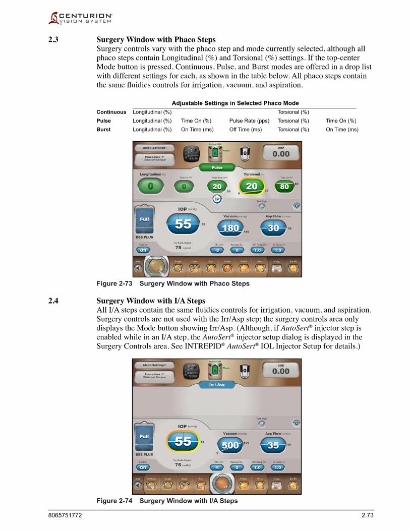
8065751772 2.73
2.3 Surgery Window with Phaco Steps Surgery controls vary with the phaco step and mode currently selected, although all
phaco steps contain Longitudinal (%) and Torsional (%) settings. If the top-center Mode button is pressed, Continuous, Pulse, and Burst modes are offered in a drop list with different settings for each, as shown in the table below. All phaco steps contain thesamefluidicscontrolsforirrigation,vacuum,andaspiration.
Adjustable Settings in Selected Phaco Mode Continuous Longitudinal (%) Torsional (%) Pulse Longitudinal (%) Time On (%) Pulse Rate (pps) Torsional (%) Time On (%) Burst Longitudinal (%) On Time (ms) Off Time (ms) Torsional (%) On Time (ms)
2.4 Surgery Window with I/A Steps AllI/Astepscontainthesamefluidicscontrolsforirrigation,vacuum,andaspiration.
Surgery controls are not used with the Irr/Asp step; the surgery controls area only displays the Mode button showing Irr/Asp. (Although, if AutoSert® injector step is enabled while in an I/A step, the AutoSert® injector setup dialog is displayed in the Surgery Controls area. See INTREPID® AutoSert® IOL Injector Setup for details.)
Figure 2-73 Surgery Window with Phaco Steps
Figure 2-74 Surgery Window with I/A Steps

2.74 8065751772
2.5 Surgery Window with AutoSert® Injector Step The AutoSert® injector step contains a dialog at the right side of the Surgery Controls
area to assist the user when setting up the INTREPID® AutoSert® IOL Injector. the Surgery Controls area also has oval display buttons that are used to set the rate of IOL lens insertion. Fluidics controls are not used with the AutoSert® injector step.
2.6 Surgery Window with Coagulation Step The Coagulation step contains just one surgical parameter: Power (%). This parameter
is displayed in the upper portion of the Surgery Controls window. This window also contains a mode indicator showing Coagulation. Fluidics controls are not used with the Coagulation step.
Figure 2-75 Surgery Window with AutoSert® Injector Step
Figure 2-76 Surgery Window with Coagulation Step

8065751772 2.75
2.7 Surgery Window with Anterior Vitrectomy Step TheVitrectomystepcontainsasurgerycontrolforCutRateparameters,andfluidics
controls for irrigation, vacuum, and aspiration parameters. The Surgery Controls area also contains a top-center Mode button indicating the current V itrectomy mode, of which four are available (Anterior Vit, Epi Removal, Peripheral Irid, Visco Asp).
Figure 2-77 Surgery Window with Anterior Vitrectomy Step

2.76 8065751772
Figure 2-78 Surgery Steps - At the bottom of the Surgery Screen are the Surgery Steps. The buttons in this area allow the surgeon to control the surgical step progression.
3. Surgery Steps Surgery screens contain step buttons at the very bottom of the screen (see Figure
2-78). These buttons represent all the surgery steps for the currently-selected doctor, plus a Setup button to quickly return to the Setup screen.
The row of Surgery Steps allows up to 12 visible buttons at one time across the bottom of the surgery screen. The Setup button is always on the far left, and the Coag & Ant Vit buttons are on the right for all surgical modes.
Procedural step buttons can be added or removed from a doctor's surgery steps by selecting or removing them in the Custom / Procedure Builder dialog.
Nine visible procedural step buttons are located between the Setup button and the Coag/Vit buttons; however, up to 16 procedural step buttons can be programmed into this space by the current doctor. When more than 9 procedural steps are programmed, and when selecting the step that is furthest left (next to the Setup button) or furthest right (next to the Coag/Vit buttons), the steps will scroll so that all steps before or after the selected step can be seen.
Setup Button
Procedural Step Buttons Stationary Step Buttons
Lens Removal Steps I/A StepsCoag Step Vit Step
Fluidics Controls
Surgery Controls
Status Panel
3. Surgery Steps

8065751772 2.77
3.1 Setup Button When the Setup button is pressed, the user will be taken to the Setup screen. To enter
the Setup screen the footpedal must be released, and the footswitch buttons must not be activated.
3.2 Procedural Step Buttons When a surgery step is selected, its button expands in size and becomes animated,
and the surgical parameters for the surgery step are displayed in the Surgery Window. Pressing Procedural Step Buttons is allowed regardless of footpedal position. A step change into Coag or Vit is allowed with the footpedal depressed, but the footpedal must be released to exit.
The Centurion®VisionSystemprovidesoperationalsurgicalstepstosupportefficientlens removal and IOL implantation. Each step allows for the adjustment of surgical parameters such as power, aspiration, and vacuum settings according to doctor preferences. These step buttons are arranged in sequential order from left to right across the bottom of the screen to provide a complete surgical procedure of different settings associated with different aspects of the procedure.
Factory-preset operating parameters for each step are programmed into the system as "AlconSettings."Thesedefaultoperatingparameterscanbetemporarilymodified,and then they can be permanently saved with a new doctor's name by using the Custom / Save As dialog.
The procedural steps are selectable from the unit’s front display screen, from the remote control unit, or from the footswitch. Selecting a new step results in a voice confirmation.(TheuserhastheabilitytoturnthevoicefeatureoffviatheCustom / Doctor Settings / Sounds dialog.)
3.3 Stationary Step Buttons Stationary step buttons are always present in Surgery screens to support Coag and
Ant Vit. These two steps are selectable from the display screen and remote control, but can be exited using either the display screen, remote control, or footswitch (if footswitchbuttonprogrammedforStep+,Step–,Step±)whenpedalisinposition0or 1.

2.78 8065751772
SURGERY MODES
Phaco Mode of Operation Whenaphaco (phacoemulsification) step is selected, IOP target, irrigation, aspiration,
longitudinal power (phaco power), and torsional amplitude (ultrasonic oscillations) are provided by the handpiece. In this mode of operation longitudinal power and ultrasonic oscillations alternately turn On and Off. Ultrasound power and torsional displacement of the phaco tip is proportional to the longitudinal and torsional settings displayed on the console front panel. The user has the ability to adjust the IOP target, aspiration rate, vacuum levels, longitudinal power, and torsional amplitude at any time during the surgical procedure via their respective adjustment dialogs or remote control. For best performance, use tips recommended by your Alcon representative.
Power/Amplitude The Longitudinal Power and Torsional Amplitude settings are increased or decreased
via adjustment dialogs in increments of 5% from a minimum of 0% to a maximum of 100%. Powerandamplitudetothehandpieceiscontrolledbyoneoftwomethods:fixedor linear footpedal control.
• Iffixedfootpedalcontrolisselected(equalstartandendvaluesinfootpedalposition3),theendvalueindicatesthefixedpoweroramplitude delivered to the handpiece. To increase or decrease the value, press an oval display button to bring up the adjustment dialog window (see left image in Figure 2-79 for example of fixedLongitudinalPoweradjustment) and use the adjustment buttons to increase ordecreasethefixedvalue.
• If linear footpedal control is selected (unequal start and end values through footpedal position 3), the starting and end values in the dialog indicate increasing or decreasing power or amplitude throughout footpedal position 3. To change the starting and end values, press an oval display button to bring up the adjustment dialog window (see right image in Figure 2-79 for example of Torsional Amplitude adjustment) and use the adjustment buttons to increase or decrease the starting and end values.
Figure 2-79 Power/Amplitude Dialogs - These two screens show a fixed Longitudinal Power dialog (left) and a linear Torsional Amplitude dialog (right), identified by the horizontal and diagonal lines in their oval display buttons. See Figure 2-67 for description of Oval Display Button Dialog.
Longitudinal Power
AmplitudeTo
rsional

8065751772 2.79
RESTING (position 0)
IRRIGATION (position 1)
IRR + ASPIRATION (position 2)
IRR + ASP + PHACO (position 3)
FOOTSWITCH ASSEMBLY
FOOTPEDAL
Figure 2-80 Continuous Phaco Surgery Screen - In this case Torsional amplitude is delivered at 20% amplitude for 100% of the time.
Figure 2-81 Footpedal Control In Phaco Modes of Operation
Phaco Timing Configurations In footpedal position 3, longitudinal power and torsional amplitude are delivered
tothephacotipthroughavarietyoftimingconfigurations.Dependingonthemodeselected (Continuous, Pulse, Burst) the timing can be continuous, or can include off-times between longitudinal/torsional pulses. The three modes are explained below.
• Continuous Phaco Mode - In this mode phaco power is delivered 100% of the time in footpedal position 3. When the Longitudinal power or Torsional amplitude setting is set to 0% (no power), then only torsional or longitudinal phaco power is delivered, for 100% of the time, to the handpiece tip. This allows the user to have continuous ultrasonic longitudinal power or torsional amplitude, if so desired. If longitudinal power and torsional amplitude are both used, then continuous phaco provides 20% of its duty cycle for longitudinal power and torsional ultrasonic oscillations for the remaining 80% when in footpedal position 3, and repeats this cycle over and over again as long as the footpedal is in position 3. This produces continuous alternations between longitudinal power and torsional amplitude.
TheusercanselectanyfixedvalueorlinearstartandendvaluesforbothLongitudinal Power % and Torsional Amplitude % when in footpedal position 3 by invoking their associated oval display button dialogs.
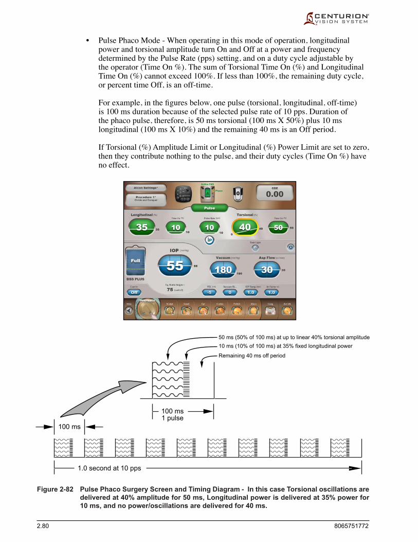
2.80 8065751772
Figure 2-82 Pulse Phaco Surgery Screen and Timing Diagram - In this case Torsional oscillations are delivered at 40% amplitude for 50 ms, Longitudinal power is delivered at 35% power for 10 ms, and no power/oscillations are delivered for 40 ms.
• Pulse Phaco Mode - When operating in this mode of operation, longitudinal power and torsional amplitude turn On and Off at a power and frequency determined by the Pulse Rate (pps) setting, and on a duty cycle adjustable by the operator (Time On %). The sum of Torsional Time On (%) and Longitudinal Time On (%) cannot exceed 100%. If less than 100%, the remaining duty cycle, or percent time Off, is an off-time.
Forexample,inthefiguresbelow,onepulse(torsional,longitudinal,off-time)is 100 ms duration because of the selected pulse rate of 10 pps. Duration of the phaco pulse, therefore, is 50 ms torsional (100 ms X 50%) plus 10 ms longitudinal (100 ms X 10%) and the remaining 40 ms is an Off period.
If Torsional (%) Amplitude Limit or Longitudinal (%) Power Limit are set to zero, then they contribute nothing to the pulse, and their duty cycles (Time On %) have no effect.
1.0 second at 10 pps
100 ms
100 ms1 pulse
50 ms (50% of 100 ms) at up to linear 40% torsional amplitude10 ms (10% of 100 ms) at 35% fixed longitudinal power
Remaining 40 ms off period
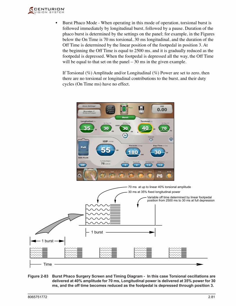
8065751772 2.81
Figure 2-83 Burst Phaco Surgery Screen and Timing Diagram - In this case Torsional oscillations are delivered at 40% amplitude for 70 ms, Longitudinal power is delivered at 35% power for 30 ms, and the off time becomes reduced as the footpedal is depressed through position 3.
• Burst Phaco Mode - When operating in this mode of operation, torsional burst is followed immediately by longitudinal burst, followed by a pause. Duration of the phaco burst is determined by the settings on the panel; for example, in the Figures below the On Time is 70 ms torsional, 30 ms longitudinal, and the duration of the Off Time is determined by the linear position of the footpedal in position 3. At the beginning the Off Time is equal to 2500 ms, and it is gradually reduced as the footpedal is depressed. When the footpedal is depressed all the way, the Off Time will be equal to that set on the panel – 30 ms in the given example.
If Torsional (%) Amplitude and/or Longitudinal (%) Power are set to zero, then there are no torsional or longitudinal contributions to the burst, and their duty cycles (On Time ms) have no effect.
1 burst
70 ms at up to linear 40% torsional amplitude30 ms at 35% fixed longitudinal power
Variable off time determined by linear footpedalposition from 2500 ms to 30 ms at full depression
1 burst
Time

2.82 8065751772
Irrigation/Aspiration Mode of Operation
Irrigation/Aspiration mode (Irr/Asp) provides irrigation and simultaneous peristaltic aspiration for use with I/A handpieces and tips. Irrigation/Aspiration control supports all surgical steps except coagulation.
In Irr/Asp mode there are only two footpedal positions. Irrigation is provided in footpedal positions 1 and 2; Aspiration is provided in footpedal position 2.
All Irr/AspstepscontainIOPtarget,vacuum,andaspirationfluidicscontrolparameters. These parameters are displayed in the lower control panel portion of the Surgery Screen. The Surgery Control Panel in the upper portion does not contain any surgical parameters, but does contain an indication of the step type; i.e., Irr /Asp.
The left screen in Figure 2-84 is an example of an Irr/Asp surgery screen. If the AutoSert® injector step is enabled (Custom/Procedure Builder/New Step/AutoSert®), the setup controls for the INTREPID® AutoSert® IOL Injector are displayed in the upper control panel, as shown in the right screen (D/C cartridge selected). This allows the nurse to prepare the AutoSert® Injector while the surgeon is performing Irr/Asp steps.
Figure 2-84 The Irrigation/Aspiration Surgery Screen
RESTING (position 0)
IRRIGATION (position 1)
IRR + ASPIRATION (position 2)
FOOTSWITCH ASSEMBLY
FOOTPEDAL
Figure 2-85 Footpedal Control in I/A Mode of Operation

8065751772 2.83
Vacuum Control The operator can adjust the vacuum limit using the front display panel or the remote
control.Theadjustablevacuumlimitrangeis0to700+mmHg(0to933+hPa),where700+mmHg(933+hPa)islimitedbyatmosphericpressure.
• Fixed Vacuum Control-Fixedvacuumcontrolprovidesafixedvacuumlimitwhen aspirating in footpedal position 2.
• Linear Vacuum Control - Linear vacuum control provides linear control of vacuum in footpedal position 2. The actual vacuum limit is proportional to the footpedal position, and tracks with footswitch penetration within the footpedal position.
Aspiration Control The operator can adjust the aspiration limit using the front display panel or the remote
control. The adjustable aspiration limit range is 5 to 60 cc/min (5 to 60 mL/min).
• Fixed Aspiration Control-Fixedaspirationcontrolprovidesafixedaspirationflowratethroughfootpedalposition2.
• Linear Aspiration Control - Linear aspiration control provides linear control of aspirationflowrateinfootpedalposition2.Aspirationflowrateiscontrolledlinearly based on settings and by footpedal penetration in position 2
Using Fill Step for Irrigation/Aspiration The Fill step can be added at any location in the procedure using the Custom/
Procedure Buildermenu.ItisrecommendedtoaddtheFillstepbeforethefirstI/Astep to facilitate removal of air from the I/A handpiece prior to use. Adding the Fill step after the last I/A step helps clean the I/A tip and handpiece.
WhentransitionedintotheFillstep,irrigationandrefluxwillbeenabledsimultaneously for up to 10 seconds. If Irrigation Fill is enabled in the Custom/System Settings/General menu, this step will be Irrigation Fill, and irrigation will be enabled withoutreflux.

2.84 8065751772
RESTING (position 0)
RESTING (position 1)
PRELOAD / INITIAL RATEPAUSEFINAL RATE (position 2)
FOOTSWITCH ASSEMBLY
FOOTPEDAL
AutoSert® IOL Injector Mode of Operation
The AutoSert® injector step can be added at any location in the procedure using the Custom/Procedure Builder menu. The AutoSert® step is typically positioned before the last I/A step.
The INTREPID® AutoSert® IOL Injector, after preparation with a loaded, single-use cartridge, gives the surgeon footpedal control of AcrySof® lens insertion in footpedal position 2. Prior to installation of the loaded cartridge, the user must select the cartridge type which is to be inserted (D/C or INTREPID® cartridge). The INTREPID® cartridge selection may not be available in all markets. Contact your Alconrepresentativeforthelatestqualifiedlens/cartridge.
When connected to the Centurion® system, the IOL injector is calibrated, and if successful, it becomes ready for use.
Figure 2-86 AutoSert® IOL Injector Screen
Figure 2-87 Footpedal Control in AutoSert® Injector Mode of Operation

8065751772 2.85
• TheCartridge Selection button is the green button located to the right of the Load Plunger button. Prior to selecting a cartridge, the button is labeled "None." After selection the button is labeled with the particular cartridge selected (see left image in Figure 2-88). The user must select either a D or C cartridge or an INTREPID® cartridge before the INTREPID® AutoSert® IOL Injector can be prepared. The cartridge type can be selected, the plunger can be loaded, and the IOL can be preloaded in an I/A step or in the AutoSert® injector step. In the AutoSert® injector step, once the cartridge type has be selected, the user can make changes to the Initial Rate/Pause/Final Rate settings.
• TheLoad Plunger button is used to install a plunger, should this be required.
• ThePreload IOL button is used by the nurse to prepare the IOL injector by advancing the lens to the preload lens position. Alternatively, the doctor can simply press the footpedal into position 2 and the preload activity will automatically proceed.
• TheRetract button is used to retract the handpiece plunger when lens insertion is completed or when otherwise necessary. Alternatively, pressing and holding the Retractbutton(Reflux)onthefootswitchcanalsobeusedtoretracttheinserter.
During each of these activities a blue Progress Bar appears to show the activity, and a red Cancel button also appears that allows the user to stop the activity at that point (see right image in Figure 2-88). Note: If the preload and retract activities are controlled with the footswitch, the progress bar and Cancel button do not appear.
After lens insertion (Initial Rate, Pause, Final Rate), the footpedal must be released and the Retract button pressed to retract the inserter.
The footpedal can be released out of position 2 during these steps, causing a pause in the insertion activity. Pressing into position 2 again causes the activity to resume from the point it stopped.
Figure 2-88 AutoSert® Injector Setup - Using the AutoSert® injector feature cannot be done until a cartridge type is selected by pressing the None button (left image). After selecting the cartridge type, the plunger can be loaded, the IOL can be preloaded (right image), the Initial Rate/Pause/Final Rate settings can be adjusted, and then the lens can be inserted.
Progress BarCancel Button

2.86 8065751772
• Initial Rate (mm/s) - Once the lens is at the Preload Lens position, the Initial Rate setting(mm/s)controlsthefixeddeliveryvelocityuptothePauseposition.
• Pause (s) - Once the Pause position is reached, a preprogrammed pause in forward advancement is initiated. This momentary pause allows internal stresses on the lens to be relieved, thus ensuring proper lens delivery.
• Final Rate (mm/s)-Thissettingcontrolsthefixedorlinearvelocityatwhichthelens is injected into the eye.
PRECAUTION: The default values for the Initial Rate and Pause ensure proper IOL injection over a worst case range of IOL size and ambient temperature conditions. Please refer to the INTREPID® AutoSert® IOL Injector DFU and consult with your Alcon representative for additional guidance in adjusting these parameters for your environment.
CAUTIONS•Do not ultrasonically clean the IOL injector connector. Ultrasonic cleaning of IOL
injector connector will cause irreparable damage.•Usecarewhenhandlinghandpiece,particularlywhencleaning.Alwaysclean
handpiece over a surface cushioned with a pad or rubber mat.• Besurehandpiececableconnectorisdrybeforeconnectingittotheconsole.•DonotdisconnectcableconnectorfromCenturion® system console until the
handpiece plunger is fully retracted.•DonotimmersetheIOLinjectorinanyfluidwhentheplungerisnotretracted.•Aspartofaproperlymaintainedsurgicalenvironment,itisrecommendedthat
a backup IOL injector be made available in the event the AutoSert® IOL injector handpiece does not perform as expected.
WARNINGS!• The INTREPID® AutoSert® IOL Injector is non-sterile and must be cleaned and
sterilized prior to, and immediately after, each use.• Never immerse the IOL injector in liquid after autoclaving; allow it to air cool for at
least 15 minutes. Quenching could result in a potentially hazardous condition for the patient.
• The AutoSert® IOL Injector delivery system is for the implantation of Alcon qualified AcrySof® foldable IOLs. Unqualified lenses shall not be used with the system. See INTREPID® AutoSert® IOL Injector DFU or AcrySof® IOL DFU, or contact your Alcon representative, for qualified lens/cartridge combinations.
• The cartridge/IOL combination listed in the DFU, along with Alcon settings, has been validated per section 5 of BS EN ISO 11979-3:2006. Appropriate use of injector handpiece settings is important for successful IOL implantation. Inappropriate use of settings may lead to a potentially hazardous condition for the patient.
• Fully retract plunger before detaching nosecone from AutoSert® IOL Injector; otherwise, this could expose non-sterile portion of shaft and result in a potentially hazardous condition for the patient.
• For the intended IOL to be implanted, the proper Cartridge profile must be selected from the driving console, and the proper plunger must be attached to the AutoSert® IOL Injector. Failure to do so can result in a potentially hazardous condition for patient.
• The metal reusable plunger must be sterilized after each use. The reusable plunger is to be installed onto the handpiece or into the wrench prior to sterilization.

8065751772 2.87
Coagulation Mode of Operation
The Coagulation mode provides approximately 1.5 MHz frequency bipolar coagulation to drive a brush or forceps in footpedal position 2. The percentage of maximum available coagulation power can be set from 0% to 100% by pressing the Power display button to bring up the adjustment dialog window. In the window select eitherfixedorlinearfootpedalcontrol,thenpresstheupordownarrowstoincreaseor decrease the power limit (s).
Coagulation begins upon entering footpedal position 2, and an audible tone is initialized. As in all other steps, coagulation settings are retained in memory so that when re-entering the Coagulation step, the previous settings are displayed.
• Fixed Coagulation Control -Fixed control provides bipolar coagulation at the preset limit when the footpedal enters position 2.
• Linear Coagulation Control - Coagulation Power begins at its lower setting when entering footpedal position 2, and it reaches its maximum setting when the footpedal is fully depressed.
Figure 2-89 The Coagulation Screen
RESTING (position 0)
RESTING (position 1)
COAGULATION (position 2)
FOOTSWITCH ASSEMBLY
FOOTPEDAL
Figure 2-90 Footpedal Control in Coagulation Mode of Operation

2.88 8065751772
WARNINGS!• Do not use the coagulation function on patients with pacemakers or implanted
defibrillatory devices. If electrosurgery is used on patients with implanted cardiac pacemakers or defibrillatory devices or pacemaker electrodes, be aware that irreparable damage to the pacemaker or defibrillatory device and its function may occur and lead to ventricular fibrillation. Please check with the pacemaker or defibrillatory device manufacturers for their recommendations.
• Failure of the HF surgical equipment (coagulation circuitry) could result in an unintended increase of output power.

8065751772 2.89
RESTING (position 0)
IRRIGATION (position 1)
IRR + ASPIRATION + CUTTING (position 2)
FOOTSWITCH ASSEMBLY
FOOTPEDAL
Anterior Vitrectomy Mode of Operation The Anterior Vitrectomy (Ant Vit) mode is used to drive a 23 gauge, pneumatically
operated, Centurion® vitrectomy cutter. Fixed and linear control of the Cut Rate is adjustable from 1 to 4000 cuts per minuteinfouroffivevitrectomymodes(onlyfixedcontrolinperipheraliridotomymode). Fixed and linear control of Vacuum and Aspirationisprovidedinallfivevitrectomymodes.
A switch on the footswitch may be assigned to enable and disable the Vit Cutter using the Custom/Doctor Settings/Footswitch tab. When the Vit Cutter is disabled, I/A functionality in footpedal position 2 is unchanged, but the Vit Cutter does not cut and the message “Cut Disabled” is displayed. The assigned Vit Cutter switch may be pressed in any footpedal position, and the function takes effect immediately.
If desired, an on-screen Vitrectomy Setup dialog appears when entering the I/A step to help the user prepare the vitrectomy cutter for surgery (see Figure 90). This feature can be enabled in the Custom/Doctor Settings/General tab, then pressing the On button in the Vit Setup window. Now when entering the Ant Vit step a window appears to guide the user through the vitrectomy setup.
Figure 2-92 Footpedal Control In Anterior Vitrectomy Mode of Operation (except for I/A Cut which is Resting/Irrigation/Irrigation+Aspiration/Irrigation+Aspiration+Cutting)
Figure 2-91 Anterior Vitrectomy Setup Dialog - This dialog appears when entering the Ant Vit step, but it must be enabled in the Custom/Doctor Settings/General tab.
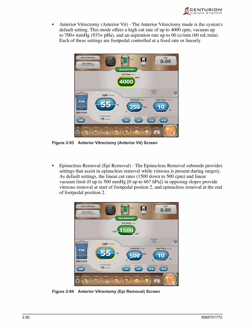
2.90 8065751772
Figure 2-93 Anterior Vitrectomy (Anterior Vit) Screen
• Anterior Vitrectomy (Anterior Vit) - The Anterior Vitrectomy mode is the system's default setting. This mode offers a high cut rate of up to 4000 cpm, vacuum up to700+mmHg(933+pHa),andanaspirationrateupto60cc/min(60mL/min).Eachofthesesettingsarefootpedalcontrolledatafixedrateorlinearly.
• Epinucleus Removal (Epi Removal) - The Epinucleus Removal submode provides settings that assist in epinucleus removal while vitreous is present during surgery. As default settings, the linear cut rates (1500 down to 500 cpm) and linear vacuum limit (0 up to 500 mmHg [0 up to 667 hPa]) in opposing slopes provide vitreous removal at start of footpedal postion 2, and epinucleus removal at the end of footpedal position 2.
Figure 2-94 Anterior Vitrectomy (Epi Removal) Screen

8065751772 2.91
• Peripheral Iridotomy (Peripheral Irid) - For a Peripheral Iridotomy using the vitrectomy probe, the open port of the probe is placed on the iris while aspirating. Once an occlusion of the iris has occurred and vacuum stability is reached, further pressingtotheveryendoffootpedaltravelwillengagethecutteratafixedcutrateas indicated by the Cut Rate setting.
Figure 2-96 Anterior Vitrectomy (Peripheral Irid) Screen
Figure 2-95 Anterior Vitrectomy (I/A Cut) Screen
• Irrigation/Aspiration Cut (I/A Cut) - Irrigation is provided in footpedal position 1; irrigation and aspiration in position 2; and irrigation, aspiration, and cutting in position 3.

2.92 8065751772LAST PAGE OF THIS SECTION
Figure 2-97 Anterior Vitrectomy (Visco Asp) Screen
• Visco Aspiration (Visco Asp) - Visco Aspiration is a submode that uses the vitrectomy probe for viscoelastic removal after an anterior vitrectomy. Using default settings, the high cut rate (4000 cpm), high linear vacuum (0 to 650 mmHg [0 to 867 hPa]), and higher aspiration rate (50 cc/min [50 mL/min]) facilitate easy viscoelastic removal with a Vitrectomy probe.

8065751772 3.1
SECTION THREEOPERATING INSTRUCTIONS
INTRODUCTION This section details a recommended setup and check-out procedure for the Centurion®
Vision System. The steps on the following pages cover preparation for cataract lens removal surgery including capsulotomy, irrigation and aspiration, coagulation, and vitrectomy using packs supplied by Alcon.
The Centurion® Vision System, including Alcon-approved consumables and accessories, constitutes a complete surgical system and is intended exclusively for use by licensed ophthalmic surgeons and their surgical teams. These surgical teams are experienced atconductingphacoemulsificationproceduresinaproperly-maintainedsurgicalenvironment(qualifiedpersonnel,availabilityofbackupequipment)andarefamiliarwiththe operation of the equipment used as outlined in operator’s manuals and directions for use (setup/checkout procedures to be completed before the surgical procedure; processing of reusable devices; maintenance; etc.).
The procedures are divided into two columns and presume a surgical team of four people: SurgeonandScrubNurseinthesterilefield,aCirculatingNurseinthenon-sterilefield,and a Sterilization Technician. In the left column a directive is given; in the right column theresponsibleteammemberisidentified.
Anyproblemspertainingtosetupandcheck-outproceduresshouldfirstbedirectedtothe Troubleshooting section of this manual. If questions still exist, contact the Alcon Technical Services Department or your local Alcon representative.
POWER UP SEQUENCE System power-up is initiated when when the Power switch is turned on and the Standby
switch is pressed. After some delay (during which the Alcon splash screen is displayed) a full-screen animation concluding with "Centurion® Vision System" is displayed. During power-up the following are displayed at the bottom of the Startup Screen:
Release: REL_xx.xx Copyright 2013 Novartis AG Access U.S. Patents list on About Dialog 2013/xx/xx 10:20
Afterpower-up,theSetupScreenisentered.Iftherearenouser-defineddoctors,thenAlconSettings becomes the currently-selected doctor, otherwise the Select Doctor dialog is opened.
SHUT DOWN SEQUENCE System shutdown may be initiated by pressing the Custom/Shutdown System button, or
by pressing the Standby switch for at least two seconds, then a Shut down the system? confirmationdialogisdisplayed.IfnoFMS,phacohandpiece,orIOLhandpieceisconnected to the system and the Standby switch is pressed, the shutdown proceeds immediately. In some system Fault conditions it may be necessary to press the Standby switchforatleastfivesecondsbeforeshutdownisinitiated.

3.2 8065751772
INITIAL SYSTEM SETUP
1. Removefootswitchfromcradleonrearofsystemandsetonfloor.Ifusingcabled footswitch, plug cable into one-of-two connectors at bottom of console's front panel. Ensure treadle and switches are not depressed.
2. Fold instrument tray down into the horizontal position. If remote control is to be used during surgery, pull a left or right loop out from the instrument tray and place the remote control in it.
3. Plug main power cord into a suitable wall outlet or receptacle. Turn Power switch ON (located at the bottom of the rear panel; this switch remains ON in the I position). Turn system power ON using the Standby switch located at the top of the right side panel.
WARNINGS! • To avoid risk of electric shock, this equipment must only be connected
to a supply mains with protective earth (ground). • Do not use multiple portable socket outlets with this system.
4. Afterpower-up,theSetupScreenisentered.Iftherearenouser-defineddoctors, then Alcon Settings becomes the currently-selected doctor. If thereareuser-defineddoctors,theSelectDoctordialogappearsallowingthe user to select an available doctor.
If creation of a new doctor is desired, press the Doctor Name button, press the Manage Doctors button, and follow the on-screen prompts.
WARNING!Ensure that appropriate Centurion® system parameters and system settings are selected prior to starting the procedure. Parameter and system settings include, but are not limited to, ultrasound mode, ultrasound power, vacuum, aspiration flow rate, bottle height, IOP, etc.
5. Verify remote control is functional by pressing its buttons and observing the system's actions.
6. Inspect the O-rings on the Ultraflow™* II I/A handpiece tip. If damaged, the O-rings must be replaced using the Ultraflow™* O-ring tool prior to sterilization.
7. Clean, inspect, and sterilize the instruments according to hospital procedure.
CAUTION The phaco handpiece must be at room temperature before use. Allow
handpiece to air cool after steam autoclave (at least 15 minutes). Never immerse in liquid to cool.
Circulating Nurse
Circulating Nurse
Circulating Nurse
Circulating Nurse
Circulating Nurse
SterilizationTechnician
SterilizationTechnician
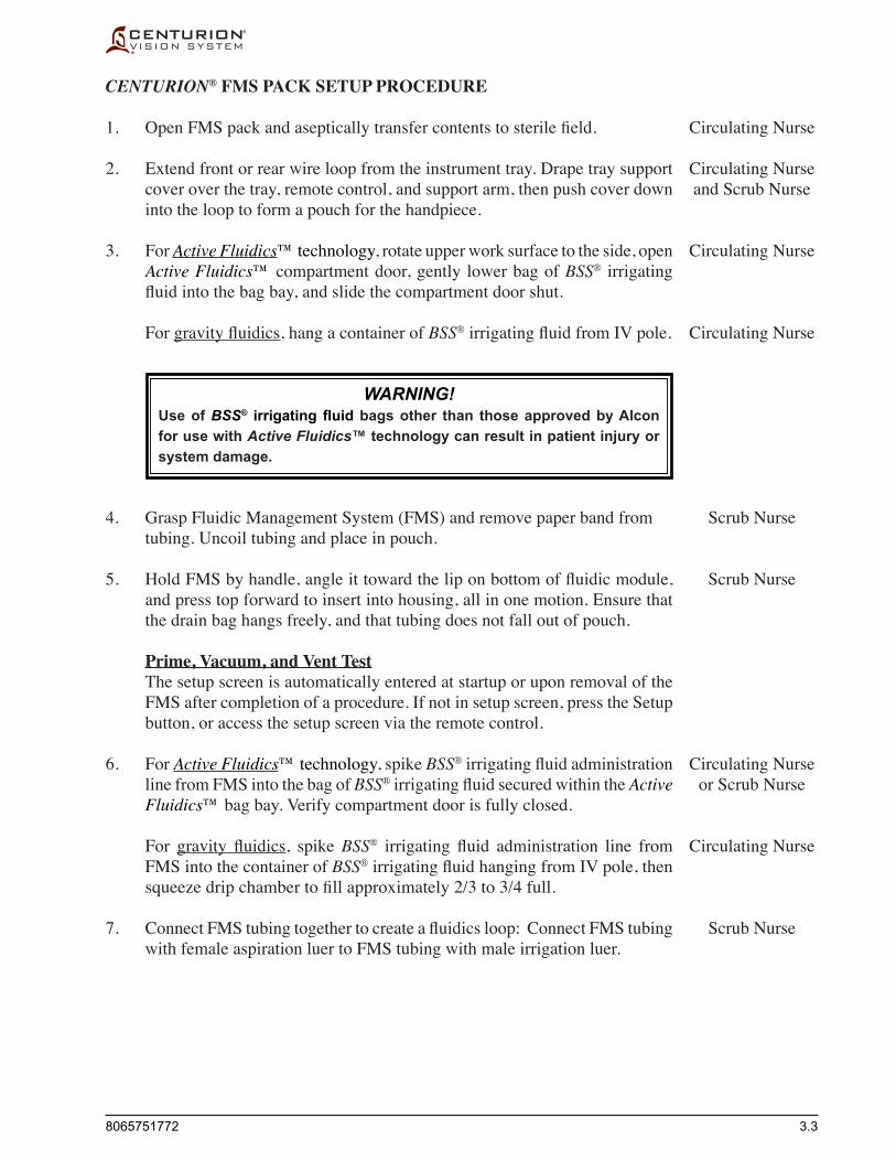
8065751772 3.3
CENTURION® FMS PACK SETUP PROCEDURE
1. OpenFMSpackandasepticallytransfercontentstosterilefield.
2. Extend front or rear wire loop from the instrument tray. Drape tray support cover over the tray, remote control, and support arm, then push cover down into the loop to form a pouch for the handpiece.
3. For Active Fluidics™ technology, rotate upper work surface to the side, open Active Fluidics™ compartment door, gently lower bag of BSS® irrigating fluidintothebag bay, and slide the compartment door shut.
For gravityfluidics, hang a container of BSS®irrigatingfluidfromIV pole.
WARNING!Use of BSS® irrigating fluid bags other than those approved by Alcon for use with Active Fluidics™ technology can result in patient injury or system damage.
4. Grasp Fluidic Management System (FMS) and remove paper band from tubing. Uncoil tubing and place in pouch.
5. HoldFMSbyhandle,angleittowardtheliponbottomoffluidicmodule,and press top forward to insert into housing, all in one motion. Ensure that the drain bag hangs freely, and that tubing does not fall out of pouch.
Prime, Vacuum, and Vent Test The setup screen is automatically entered at startup or upon removal of the
FMS after completion of a procedure. If not in setup screen, press the Setup button, or access the setup screen via the remote control.
6. For Active Fluidics™ technology, spike BSS®irrigatingfluidadministrationline from FMS into the bag of BSS®irrigatingfluidsecuredwithintheActive Fluidics™ bag bay. Verify compartment door is fully closed.
For gravity fluidics, spike BSS® irrigating fluid administration line fromFMS into the container of BSS®irrigatingfluid hanging from IV pole, then squeezedripchambertofillapproximately2/3to3/4full.
7. ConnectFMStubingtogethertocreateafluidicsloop:ConnectFMStubingwith female aspiration luer to FMS tubing with male irrigation luer.
Circulating Nurse
Circulating Nurseand Scrub Nurse
Circulating Nurse
Circulating Nurse
Scrub Nurse
Scrub Nurse
Circulating Nurseor Scrub Nurse
Circulating Nurse
Scrub Nurse

3.4 8065751772
Scrub Nurse8. Ensure correct Doctor and Procedure setting are selected. Press Prime FMS on the Setup screen or Enter on the remote control to initiate the priming/testsequence.Thesystemperformsthreefunctions:drawfluid,vacuum test, and vent test.
ForgravityfluidicstheIV pole automatically elevates to the priming position during the priming test, then returns to its home position after successful completion the testing sequence.
WARNINGS!• IV pole rises automatically. To avoid stretching drip chamber tubing,
and possibly pulling drip chamber out of bottle, tubing must hang freely with no interference.
• If using gravity fluidics, keep clear of IV pole when it is in motion to prevent skin, hair, and/or clothing from becoming trapped in the IV pole mechanism.
After successful completion of the priming sequence, the FMS prime status indicator at top of display screen (Active Fluidics™ FMS or Gravity FMS) changes from red (not primed) to green (primed), and the setup automatically switches to the Fill step.
If the priming/test sequence fails, an advisory message is displayed.
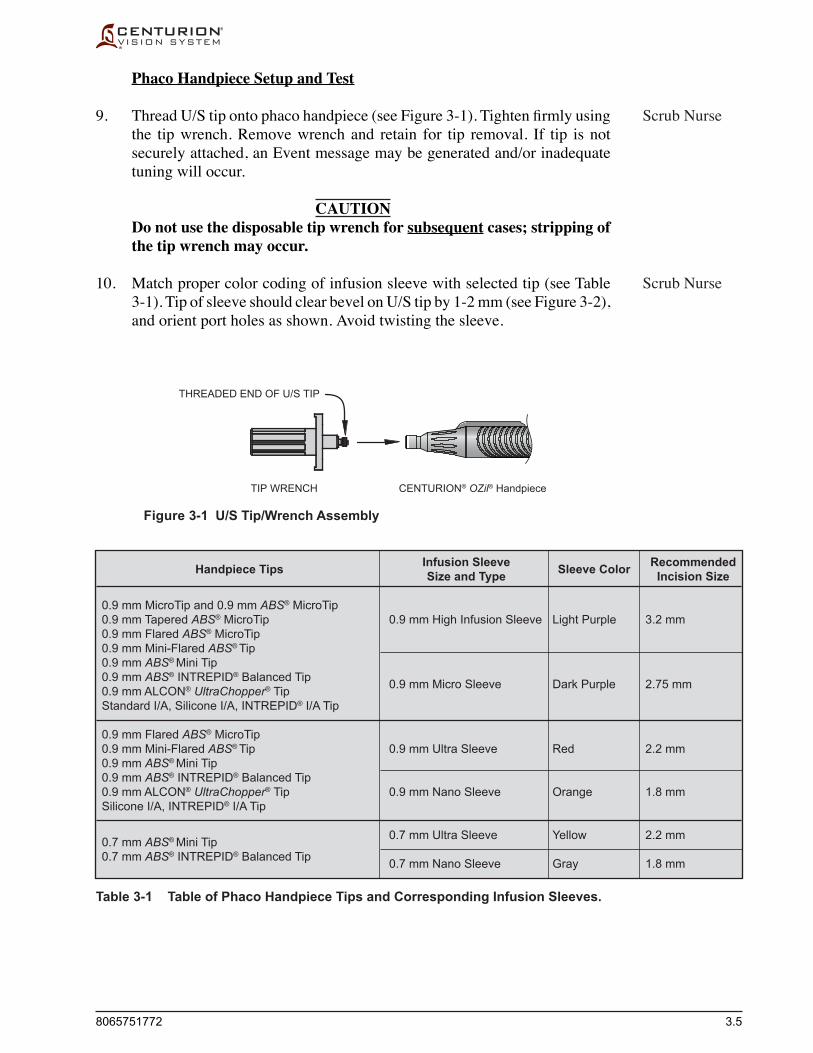
8065751772 3.5
Infusion SleeveSize and Type
0.9 mm High Infusion Sleeve
0.9 mm Micro Sleeve
0.9 mm Ultra Sleeve
0.9 mm Nano Sleeve
0.7 mm Ultra Sleeve
0.7 mm Nano Sleeve
Sleeve Color
Light Purple
Dark Purple
Red
Orange
Yellow
Gray
RecommendedIncision Size
3.2 mm
2.75 mm
2.2 mm
1.8 mm
2.2 mm
1.8 mm
Handpiece Tips
0.9 mm MicroTip and 0.9 mm ABS® MicroTip0.9 mm Tapered ABS® MicroTip0.9 mm Flared ABS® MicroTip0.9 mm Mini-Flared ABS® Tip0.9 mm ABS® Mini Tip0.9 mm ABS® INTREPID® Balanced Tip0.9 mm ALCON® UltraChopper® TipStandard I/A, Silicone I/A, INTREPID® I/A Tip
0.9 mm Flared ABS® MicroTip0.9 mm Mini-Flared ABS® Tip0.9 mm ABS® Mini Tip0.9 mm ABS® INTREPID® Balanced Tip0.9 mm ALCON® UltraChopper® TipSilicone I/A, INTREPID® I/A Tip
0.7 mm ABS® Mini Tip0.7 mm ABS® INTREPID® Balanced Tip
Table 3-1 Table of Phaco Handpiece Tips and Corresponding Infusion Sleeves.
Figure 3-1 U/S Tip/Wrench Assembly
Phaco Handpiece Setup and Test
9. ThreadU/Stipontophacohandpiece(seeFigure3-1).Tightenfirmlyusingthe tip wrench. Remove wrench and retain for tip removal. If tip is not securely attached, an Event message may be generated and/or inadequate tuning will occur.
CAUTIONDo not use the disposable tip wrench for subsequent cases; stripping of the tip wrench may occur.
10. Match proper color coding of infusion sleeve with selected tip (see Table 3-1). Tip of sleeve should clear bevel on U/S tip by 1-2 mm (see Figure 3-2), and orient port holes as shown. Avoid twisting the sleeve.
TIP WRENCH
THREADED END OF U/S TIP
CENTURION® OZil® Handpiece
Scrub Nurse
Scrub Nurse

3.6 8065751772
Figure 3-2 Phaco Handpiece Tip/Infusion Sleeve Preparation
Figure 3-3 Connect Phaco Handpiece to FMS Tubing and Centurion® System Connector Panel (CENTURION® OZil® handpiece shown).
CENTURION
Aspiration Line(blue female luer)
Connect cable to front panel connectoridentified by handpiece icon: • CENTURION® OZil® handpiece • INFINITI® OZil® handpiece
Irrigation Line(clear male luer with white luer lock)
U/S Tip
CENTURION® OZil® Handpiece
U/S Tip
Straight Kelman® FlaredStraight
FlaredKelman®
Infusion Sleeve
Infusion SleevePort Hole turned 90° to tip bevel
1.0 to 2.0 mm
Figure 3-4 Preparing Test Chamber and Placing Handpiece in Pouch.
BSS® irrigating fluidin test chamber
Slide test chamberover handpiece tip
Place handpiecevertically in pouchformed with drape

8065751772 3.7
11. Remove protective cap from handpiece cable connector by retracting its sheath and releasing cap. Line up red dot on handpiece cable connector with red dot on front panel connector and plug cable into console (see Figures 2-2 & 3-3). If CENTURION® OZil® handpiece, plug into one of the top two connectors. If INFINITI® OZil® handpiece, plug into bottom connector.
12. From FMS, connect the female luer on aspiration line to male aspiration port on handpiece. Connect male luer on irrigation line to female irrigation port on handpiece. If Centurion® handpiece, turn the white luer lock clockwise tolockirrigationfittingtohandpiece(seeFigure3-3).
13. Hold handpiece with tip pointed down into test chamber (see Figure 3-4) andactivateFillonthesetupscreen.Whileobservingstreamoffluidfromirrigation and aspiration ports, filltestchambercompletelyandslideitoverend of handpiece. Ensure no air bubbles are present in test chamber. Press handpiece into instrument tray pouch with tip pointed up, and secure irrigation/aspiration lines to clips on top of tray. Ensure tubing is not kinked.
WARNINGS!If stream of fluid is weak or absent while filling test chamber, good fluidics response will be jeopardized. Good clinical practice dictates the testing for adequate irrigation and aspiration flow prior to entering the eye.
Ensure that the tubings are not occluded during any phase of operation.
When using a bimanual procedure, ensure the irrigation handpiece and settings have sufficient flow characteristics. Use of irrigation handpieces or settings with insufficient flow characteristics may result in a fluidic imbalance and may cause a shallowing or collapsing of the anterior chamber.
If an INFINITI® OZil® handpiece is connected to the bottom connector, and Ultrachop step is added to surgery steps, press the Swap Phaco / UltraChop button and repeat steps 12 and 13.
14. Activate Test Handpiece on the setup screen. The test consists of a handpiece tuningexerciseandfluidicflowcheck.Ifhandpiecefailstuningorflowtest,an advisory is displayed. The handpiece tuning process can be aborted at any time by pressing cancel (X).
WARNINGS!If the handpiece test chamber is collapsed after tuning, there is a potential of low irrigation flow through the handpiece and may result in a fluidic imbalance. This, in turn, may cause a shallowing or collapsing of the anterior chamber.
Good clinical practice dictates testing for adequate irrigation, aspiration flow, reflux, and operation as applicable for each handpiece prior to entering eye.
Scrub Nurse
Scrub Nurse
Scrub Nurse
Scrub Nurse

3.8 8065751772
Bottle Height
Patient Eye Level (P
EL)
PEL ValueCENTURIONVISION SYSTEM
for Gravity Fluidics
15. After successfully testing handpiece you must adjust and verify the Patient Eye Level (PEL) until the console PEL light aligns with the patient's eye level(seeFigure3-5).Ifenabled,aPELverificationstepisprovidedinthesetup screen. When alignment is complete, press the green check mark to entertheSurgeryScreenforthefirststepoftheprocedure.
PRECAUTION: After a successful tuning of the handpiece, and if PEL verificationisdisabled,thefirststepofthelensremovalprocedureisenteredwithout verifying PEL.
Figure 3-5 Setting Patient Eye Level (PEL).
Scrub Nurse

8065751772 3.9
3. Remove aspiration and irrigation lines from the phaco handpiece and connect to the I/A handpiece. For I/A handpieces equipped with a locking irrigation luer, turn the white luer lock clockwise to lock irrigation line to handpiece.
4. In Surgery screen, and with handpiece level with instrument tray, depressfootswitchtoposition1tostreamirrigationfluidfromtheirrigationport.ActivatetherefluxfunctiontostreamfluidfromtheI/Atip’saspirationport.Observethestreamofirrigatingfluidfromtheirrigation and aspiration ports. Ensure no air bubbles remain in irrigation or aspiration pathways before continuing procedure.
WARNING!If stream of fluid is weak or absent, good fluidics response will be jeopardized. Good clinical practice dictates the testing for adequate irrigation and aspiration flow prior to entering the eye.
IRRIGATION/ASPIRATION HANDPIECE SETUP
1. If using Ultraflow™* II I/A handpiece with threaded tip adapter, follow the directions in this step.
ThreadI/AtipontoI/Ahandpiece.TightenfirmlyusingtheI/Atipwrench.Remove I/A tip wrench and retain for future tip removal.
CAUTIONUse of a tool other than Alcon tip wrench may cause damage to the I/A tip and handpiece.
2. Thread infusion sleeve over the I/A tip until sleeve clears end of I/A tip by 1-2 mm (see Figure 3-6). Avoid twisting of the Sleeve. Orient port holes as shown and ensure that aspiration holes are not obstructed.
Scrub Nurseor
SterilizationTechnician
Scrub Nurse
Scrub Nurse
Surgeonor
Scrub Nurse
Figure 3-6 I/A Handpiece Tip/Infusion Sleeve Preparation.
I/A Tip
Infusion Sleeve
UltraFlow™* II I/A HandpieceInfusion Sleeve
1.0 to 2.0 mm
Aspiration Holes in I/A Tip

3.10 8065751772
INTREPID® AUTOSERT® IOL INJECTOR SETUP
1. If AutoSert® injector step is not already shown at bottom of Surgery screen for this doctor, add it to the steps using the Custom/Procedure Builder/New Step window. The AutoSert® injector step is typically positioned before the last Irr/Asp step.
2. Plug INTREPID® AutoSert® IOL Injector Handpiece cable into one of the top two handpiece connectors on the front connector panel. (Usually itisthesecondofthetwoasthefirstisusedbythephacohandpiece.)
3. Enter the AutoSert® injector step (or Irr/Asp step with AutoSert® setup in its Surgery Controls area).
Select a Cartridge Prior to loading plunger and preloading IOL, the user must select the
cartridge type which is to be inserted (D/C or INTREPID® cartridge). With no cartridge selected, the cartridge type button is labeled "None."
4. Press the green cartridge type button to make a selection (INTREPID® cartridge selection may not be available in all markets). Contact your Alconrepresentativeforthelatestqualifiedlens/cartridge.
Remove a Plunger It may be necessary to remove one type of plunger and replace it with
anothertypeinthesterilefieldtoaccommodateeithertheD/C cartridge or INTREPID® cartridge.
5. With plunger fully retracted, remove cartridge from IOL injector handpiece.
6. Detach nosecone from IOL injector handpiece by rotating the nosecone counter-clock-wise, then carefully sliding it away from the IOL injector handpiecesoitdoesnotdeflecttheplunger.
7. With nosecone removed (see Figure 3-7), remove the plunger by grasping it where indicated and pulling it away from IOL injector handpiece.
8. Re-attach nosecone onto IOL injector handpiece.
Circulating Nurseor
Scrub Nurse
Scrub Nurse
Scrub Nurse
Scrub Nurse
Scrub Nurse
Scrub Nurse
Scrub Nurse
Figure 3-7 Removing Plunger from INTREPID® AutoSert® IOL Injector.
Grasp plunger here
and pull away from IOL handpiece

8065751772 3.11
Load a Plunger If a plunger needs to be installed, perform this procedure when an I/A
step or AutoSert® injector step is entered. The IOL injector handpiece can be prepared with two types of plungers: the reusable metal plunger or the single-use soft tip plunger. The reusable metal plunger is designed for use with Monarch C and D cartridges. The single-use soft tip plunger is designed for use with the INTREPID® cartridge.
9. Slide sterile plunger into sterile wrench, then connect plunger/wrench onto nosecone of sterile IOL injector handpiece. Press Load Plunger button (See Alcon® INTREPID® AutoSert® IOL Injector Handpiece DFU).
10. After plunger is loaded onto nosecone of sterile IOL injector handpiece, remove wrench. The IOL injector handpiece is ready for the IOL cartridge.
Preload an IOL Prior to entering the eye, the plunger must be moved forward to the
preload lens position.
11. Load IOL into cartridge, then insert loaded IOL cartridge onto tip of IOL injector handpiece (See Alcon® INTREPID® AutoSert® IOL Injector Handpiece DFU).
12. Press Preload IOL button. The AutoSert® handpiece is ready for use when the preload sequence is complete.
Make Final Adjustments
13. In the AutoSert® injector step, and prior to inserting the lens into the patient's eye, set the doctor's preferred Initial Rate (mm/s), Pause (s), and Final Rate (mm/s) settings. The FinalRatecanbesetforfixedorlineardelivery.
PRECAUTION: The default values for the Initial Rate and Pause ensure proper IOL injection over a worst case range of IOL size and ambient temperature conditions. Please refer to the INTREPID® AutoSert® IOL Injector DFU and consult with your Alcon representative for additional guidance in adjusting these parameters.
Cautions and Warnings for AutoSert® IOL injector on next page
Scrub Nurse
Scrub Nurse
Scrub Nurse
Scrub Nurse
Circulating Nurseor
Scrub Nurse

3.12 8065751772
CAUTIONS•Do not ultrasonically clean the AutoSert® IOL Injector connector. Ultrasonic
cleaning will cause irreparable damage.•UsecarewhenhandlingAutoSert® IOL Injector, particularly when cleaning. Always
clean handpiece over a surface cushioned with a pad or rubber mat.• Besurehandpiececableconnectorisdrybeforeconnectingittotheconsole.•DonotdisconnectcableconnectorfromCenturion® system console until the IOL
Injector plunger is fully retracted.•Donot immerse theAutoSert® IOLInjector inanyfluidwhentheplunger isnot
retracted.•As part of a properlymaintained surgical environment, it is recommended that
a backup IOL injector be made available in the event the AutoSert® IOL injector handpiece does not perform as expected.
WARNINGS!• The INTREPID® AutoSert® IOL Injector is non-sterile and must be cleaned and
sterilized prior to, and immediately after, each use.• Never immerse the IOL injector in liquid after autoclaving; allow it to air cool for at
least 15 minutes. Quenching could result in a potentially hazardous condition for the patient.
• The AutoSert® IOL Injector delivery system is for the implantation of Alcon qualified AcrySof® foldable IOLs. Unqualified lenses shall not be used with the system. See INTREPID® AutoSert® IOL Injector DFU or AcrySof® IOL DFU, or contact your Alcon representative, for qualified lens/cartridge combinations.
• The cartridge/IOL combination listed in the DFU, along with Alcon settings, has been validated per section 5 of BS EN ISO 11979-3:2006. Appropriate use of injector handpiece settings is important for successful IOL implantation. Inappropriate use of settings may lead to a potentially hazardous condition for the patient.
• Fully retract plunger before detaching nosecone from AutoSert® IOL Injector; otherwise, this could expose non-sterile portion of shaft and result in a potentially hazardous condition for the patient.
• For the intended IOL to be implanted, the proper Cartridge profile must be selected from the driving console, and the proper plunger must be attached to the AutoSert® IOL Injector. Failure to do so can result in a potentially hazardous condition for patient.
• The metal reusable plunger must be sterilized after each use. The reusable plunger is to be installed onto the handpiece or into the wrench prior to sterilization.

8065751772 3.13
CENTURION® ULTRAVIT® PROBE SETUP(using Vitrectomy Setup dialog)
When the Anterior Vitrectomy step is entered, the Vitrectomy Setup dialog appears (see Figure 3-8) unless turned Off in the Doctor Settings screen. This setup screen assists the user through the proper set up and test of the selected probe.
If the Vitrectomy Setup dialog is turned Off, you can either turn the Vitrectomy Setup dialog On (Custom/Doctor Settings/General), or proceed three more pages to CENTURION® ULTRAVIT® PROBE SETUP (without using Vitrectomy Setup dialog).
1. Peellidandasepticallytransfercontentsofpacktosterilefield.
2. Press the Ant Vit step button; the Vitrectomy Setup dialog appears.
NOTE: In the next few steps the user will be instructed to press buttons on the Vitrectomy Setup dialog. These buttons can be pressed on the display screen, or they can be activated using the Parameter Selection keys and Enter key on the remote control.
3. Connect to console Vit port - Connect black and gray pneumatic tubing connectors from the Centurion® UltraVit® Probe to left and right Vit ports, respectively, on the front panel of the Centurion® Vision System (see Figures 2-2 & 3-8 & 3-9). Turn tubing connectors clockwise until they click securely in place.
Figure 3-8 Vitrectomy Setup Dialog - After performing a Vitrectomy Setup step, pressing the Next button brings up the dialog for the next setup step. In step 6, the Fill button allows the user to prime the probe and to fill a test vessel for proper testing of the probe. Pressing the Test button initiates an automated test sequence which verifies secure pneumatic connections, then applies pneumatic activation at a reduced cut rate for visual verification of probe actuation.
Circulating Nurse
Scrub Nurse
Scrub Nurse

3.14 8065751772
4. Connect aspiration tubing - Disconnect FMS irrigation and aspiration tubing connectors from phaco handpiece. Connect FMS blue aspiration tubing connector to probe's blue aspiration tubing connector (see Figure 3-9). Press Next button.
5. Connect irrigating cannula - Connect FMS white irrigation tubing connector to irrigating cannula (see Figure 3-9). Press Next button.
6. Press Fill then press Test - Priming of the vitrectomy probe is required prior to use. With tip of probe and irrigating cannula in a cup of sterile fluid,presstheFill button. Ensure all air bubbles have been removed from all tubing connected to the probe prior to use.
Verify probe actuation - While observing cutting port of probe, held undersurfaceofsterilefluid,presstheTest button. The system intitiates anautomatedtestsequenceconfirmingsecureconnectionsandfacilitatesvisualization of probe cutter by applying a brief period of reduced cut rate. The cutter should fully open and close when actuated.
7. The Anterior Vit surgery screen appears on the front display panel. Switchingbetweenfivedifferentvitrectomytypesisdonebypressingthe Mode button (Anterior Vit) at top center of surgery screen. The vitrectomy probe is ready for surgery.
Cautions and Warnings for Centurion® UltraVit® Probe are on next page
Male LuerIrrigating Cannula
Centurion® UltraVit® Probe
Irrigation Tubing
Pneumatic TubingClear
Black Striped
Aspiration Tubing
From Centurion®
Fluidic ManagementSystem (FMS)Female LuerMale Luer
Gray Fitting
Connect to Centurion®
Front Connector Panel
Black Fitting
Figure 3-9 Preparation of Centurion® UltraVit® Probe and Irrigating Cannula with Irrigation/aspiration and pneumatic tubings.
Scrub Nurse
Scrub Nurse
Scrub Nurse
Scrub Nurse
Scrub Nurse
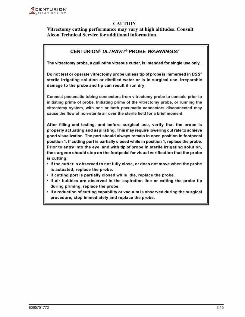
8065751772 3.15
CAUTIONVitrectomy cutting performance may vary at high altitudes. Consult Alcon Technical Service for additional information.
CENTURION® ULTRAVIT® PROBE WARNINGS!
The vitrectomy probe, a guillotine vitreous cutter, is intended for single use only.
Do not test or operate vitrectomy probe unless tip of probe is immersed in BSS® sterile irrigating solution or distilled water or is in surgical use. Irreparable damage to the probe and tip can result if run dry.
Connect pneumatic tubing connectors from vitrectomy probe to console prior to initiating prime of probe. Initiating prime of the vitrectomy probe, or running the vitrectomy system, with one or both pneumatic connectors disconnected may cause the flow of non-sterile air over the sterile field for a brief moment.
After filling and testing, and before surgical use, verify that the probe is properly actuating and aspirating. This may require lowering cut rate to achieve good visualization. The port should always remain in open position in footpedal position 1. If cutting port is partially closed while in position 1, replace the probe. Prior to entry into the eye, and with tip of probe in sterile irrigating solution, the surgeon should step on the footpedal for visual verification that the probe is cutting:• If the cutter is observed to not fully close, or does not move when the probe
is actuated, replace the probe.• If cutting port is partially closed while idle, replace the probe.• If air bubbles are observed in the aspiration line or exiting the probe tip
during priming, replace the probe.• If a reduction of cutting capability or vacuum is observed during the surgical
procedure, stop immediately and replace the probe.

3.16 8065751772
CENTURION® ULTRAVIT® PROBE SETUP(without using Vitrectomy Setup dialog)
1. Peellidandasepticallytransfercontentstosterilefield.
2. Press the Ant Vit step button; the Anterior Vit surgery screen appears. If it is desired to have a Vit step as a part of the procedure, then it must be added in the Procedure Builder.
3. Connect black and gray pneumatic tubing connectors from the CENTURION® UltraVit® Probe to left and right Vit ports, respectively, on the front panel of the Centurion® Vision System (see Figures 2-2 & 3-10). Turn tubing connectors clockwise until they click securely in place.
4. Disconnect FMS irrigation and aspiration tubing connectors from phaco handpiece. Connect FMS female luer aspiration connector to aspiration line of vitrectomy probe. Connect FMS male luer irrigation connector to irrigating cannula (see Figure 3-10).
Circulating Nurse
Scrub Nurse
Scrub Nurse
Scrub Nurse
Scrub Nurse
Scrub Nurse
Figure 3-10 Preparation of Centurion® UltraVit® Probe and Irrigating Cannula with Irrigation/aspiration and pneumatic tubings.
5. Priming of the vitrectomy probe is required prior to use, and can be performed using one of two methods. With tip of probe and irrigating cannulainacupofsterilefluid:
• Independentlyuseirrigationbydepressingthefootpedaltoposition1 to remove air bubbles from the probe’s irrigation line, and then use refluxtoremoveairbubblesfromtheprobe’saspirationtubing.
•UsetheFillcommand,ifenabledintheProcedureBuilderandplacedbefore the Vit step, to simultaneously remove air bubbles from the irrigation and aspiration lines. When completed, the system will proceed to the selected Vit step.
Ensure all air bubbles have been removed from all tubing connected to the probe prior to use.
6. Testing of the vitrectomy probe should be performed prior to use. With tipofprobeandirrigatingcannulainacupofsterilefluid,depressfootpedal to the cut position and observe probe's cutting port (to facilitate visualization, reduce cut rate). The cutter should fully open and close when actuated, and remain open when footpedal is released to position 0.
Cautions and Warnings for Centurion® UltraVit® Probe are on prior page
Male LuerIrrigating Cannula
Centurion® UltraVit® Probe
Irrigation Tubing
Pneumatic TubingClear
Black Striped
Aspiration Tubing
From Centurion®
Fluidic ManagementSystem (FMS)Female LuerMale Luer
Gray Fitting
Connect to Centurion®
Front Connector Panel
Black Fitting

8065751772 3.17
COAGULATION HANDPIECE SETUP
1. Using aseptic techniques, plug new or sterilized handpiece cable connectors into Centurion® Vision System front connector panel.
2. Plug connector into new or sterilized coagulation handpiece.
3. Coagulation handpiece is ready.
INTREPID® CAPSULOTOMY DEVICE SETUP
1. If the Capsulotomy step is not already shown at bottom of Surgery screen for this doctor, it can be added using the Custom/Procedure Builder/New Step window.
2. Carefully remove INTREPID® Capsulotomy Device from plastic tray by gently bending tray and exposing the top half of device.
CAUTIONCare should be taken as to not damage the distal end of the device.
3. Unwind cable and plug INTREPID® Capsulotomy Device into its designated connector on the front connector panel.
4. Press the Test ICD button at bottom of Setup Screen.
5. Device must be enabled by pressing the Enable button at bottom of Setup Screen, or by pressing the Refluxfootswitchbutton.
Scrub Nurse
Scrub Nurse
Circulating Nurse or
Scrub Nurse
Scrub Nurse
Scrub Nurse
Scrub Nurse
Scrub Nurseor
Surgeon

3.18 8065751772LAST PAGE OF THIS SECTION
THIS PAGE INTENTIONALLY BLANK

8065751772 4.1
INTRODUCTION
This section of the manual is designed to inform the operator of basic care and maintenance of the instrument. If a problem occurs on the instrument, contact Alcon Technical Support or your local Alcon representative and give details of the breakdown circumstances and effects. If there is an Event message, write down the number and message exactly as it appears on the screen. From these elements, a specialized technician will evaluate the problem and determine the maintenance requirements.
For optimum performance, it is the user’s responsibility to schedule preventive maintenance service on the system and its accessories at least one time each year. Alcon’s Field Service Engineers are trained and equipped to provide the highest quality of workmanship.
CAUTION
There are no operator replaceable parts other than the fuse. Contact Alcon Technical Services for all servicing issues.
WARNING!The Centurion® Vision System battery can only be serviced by a factory-trained Alcon service engineer. Access by untrained personnel can lead to injury.
SECTION FOURCARE AND MAINTENANCE

4.2 8065751772
UPON COMPLETION OF THE DAY'S SURGERY SCHEDULE
STEP ONE: Clean handpieces, cables, forceps, etc., as instructed in DFU's supplied with each accessory.
WARNING!If in the medical opinion of the physician a patient with a prion related disease undergoes a high risk procedure, the instrument should be destroyed or be processed according to local requirements.
STEP TWO: Remove bag of BSS®irrigatingfluidfromActive Fluidics™ bag bay, or remove irrigation container from IV pole hanger, and set aside. Remove spike from BSS®irrigatingfluidanddiscardtubing.
STEP THREE: Eject FMS and discard.
STEP FOUR: Slide door shut over Active Fluidics™ bagbay,orflipIVpolehangerto its storage position.
STEP FIVE: Select Custom/Shutdown from the Surgery Screen. Select OK. If used, IV pole will go down to storage position before unit shuts off.
or
Press Standby power switch located at top of right side panel to remove operating power from the system. If used, IV pole will go down to storage position before unit shuts off.
WARNING!If used, keep clear of the IV pole when it is in motion to prevent skin, hair, and/or clothing from being trapped in the IV pole mechanism.
STEP SIX: Turn the primary AC power switch OFF. It is located at the bottom of the rear panel.
STEP SEVEN: Disconnect the power cable from the wall receptacle and wind the cable around the cord wrap.

8065751772 4.3
STEP EIGHT: Inspect, and if required, clean footswitch bottom cover and under footpedal with water, alcohol, or mild soap and water. Remove any debris (see Figure 4-1).
CAUTIONDebris, including fluid residue, stuck on footswitch bottom or under rear section of treadle may cause temporary malfunction of the footswitch.
Figure 4-1 Footswitch Cleaning - Clean under footpedal and footswitch to remove debris that can interfere with its operation.
STEP NINE: If required, the console panels, the footswitch, and the remote control may be wiped with alcohol, mild soap and water, or any germicidal solution that is compatible with the plastic parts.
CAUTIONS• Do not clean console or accessories using solvents, abrasives, or any cleaner
that is not compatible with plastic parts made of LEXAN EXL9112. Damage may result.
• Avoid spilling BSS® solution, or moisture of any kind, around the electrical handpiece connectors.
• Do not spray any liquid (i.e. cleaning solution or water) upward into the console vents.
STEP TEN: Hang the footswitch on the footswitch hanger/charging station at the bottom of the rear panel.
Clean and remove debris fromthis area under the footpedal, andfrom bottom of footswitch.

4.4 8065751772
CARE AND CLEANING
The following tips are recommended for proper care of the Centurion® Vision System: • Theconsolepanels,thefootswitch,andtheremotecontrolmaybewipedwith
alcohol, mild soap and water, or any germicidal solution that is compatible with the plastic parts; instructions begin on the prior page.
• Thetouchscreenmaybecleanedwithasoft,non-abrasiveclothtowelandamildcommercially-available window cleaner. Apply the cleaner to the towel rather than the touch screen.
• Followcleaning and maintenance schedules outlined in this section of the manual. • Periodicallycheckchassisappearance. • Payattentiontocorrectoperationofcontrols,connectors,andindicators. • Damagedhardwaremustbereplacedtoensuresafeoperation.CallAlcon
Technical Services for assistance.
WARNING!A qualified technician must perform a visual inspection of the following components every twelve months: • Warning Labels (see section one of this manual) • Power Cord • FusesIn case of a deficiency, do not use the system; call Alcon Technical Services.
A qualified technician must check ground continuity and leakage current every twelve months to ensure they are within the limits of the applicable standards (for example: EN60601-1/IEC60601-1). Values must be recorded, and if they are above the limits of the applicable standards, or 50% above initial measurement, do not use the system; call Alcon Technical Services.

8065751772 4.5
STERILIZATION INSTRUCTIONS
The sterilization settings provided in Table 4-1 have been validated by Alcon Laboratories, Inc. as being CAPABLE of sterilizing the instruments for re-use. It remains the responsibility of the processor to ensure that the processing as actually performed using equipment, materials, and personnelinthefacilityachievethedesiredresult.Thisrequiresverificationandroutinemonitoringof the process. Likewise, any deviation by the processor from the instructions provided with the instrument's DFU should be properly evaluated for effectiveness and potential adverse consequences. Please refer to nationally recognized standards, or to your facility’s standard procedures.
STERILIZER TYPE SAMPLE TEMPERATURE MINIMUM EXPOSURE MINIMUM DRYING CONFIGURATION TIME (MINUTES) TIME (MINUTES)
Gravity Displacement Wrapped 132 ºC (270 ºF) 15 15
Gravity Displacement Unwrapped 132 ºC (270 ºF) 10 N/A
Pre-vacuum Wrapped 135 ºC (275 ºF) 3 16
Pre-vacuum Unwrapped 132 ºC (270 ºF) 4 N/A
Table 4-1 Sterilization Temperature and Time Settings.

4.6 8065751772
FUSE REPLACEMENT
1. Turn the primary AC power switch OFF. It is located at the bottom of the rear panel on the power module. Unplug power cord from power module.
2. Insertaflatsurfacedinstrumentalongtheleftsideofthepower module fuse door. Pressingtheflatinstrumenttotherightagainstthefusedoor,pullouttoreleasedoor.
CAUTION
The fuse door must be pressed gently to ensure it does not break.
3. With fuse door open, grasp the fuse holder and pull it out from the power module.
4. Gently remove and replace fuses. Contact Alcon Technical Services for the correct rating and size.
5. Reinsert fuse holder into power module and shut the fuse door.
6. Plug power cord into power source.
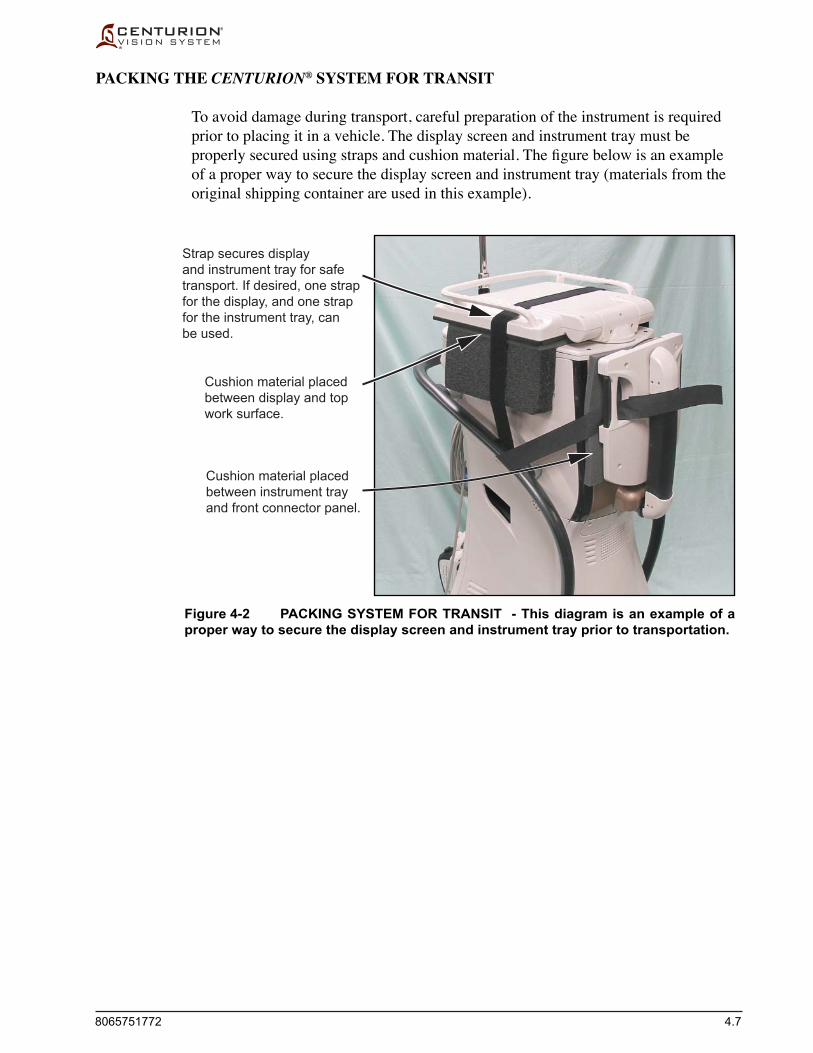
8065751772 4.7
Figure 4-2 PACKING SYSTEM FOR TRANSIT - This diagram is an example of a proper way to secure the display screen and instrument tray prior to transportation.
Strap secures displayand instrument tray for safetransport. If desired, one strapfor the display, and one strapfor the instrument tray, canbe used.
Cushion material placedbetween display and topwork surface.
Cushion material placedbetween instrument trayand front connector panel.
PACKING THE CENTURION® SYSTEM FOR TRANSIT
To avoid damage during transport, careful preparation of the instrument is required prior to placing it in a vehicle. The display screen and instrument tray must be properlysecuredusingstrapsandcushionmaterial.Thefigurebelowisanexampleof a proper way to secure the display screen and instrument tray (materials from the original shipping container are used in this example).

4.8 8065751772LAST PAGE OF THIS SECTION
SETTING UP THE RECONSTITUTION RACK
The reconstitutionrackisusedtoholduptosixfluidbagsfortheActive Fluidics™ system, making it convenient for the surgery team to prepare the system for each surgery. The rack comes in a box that must be opened and set up as instructed below.
STEP ONE: Remove reconstitution rack from shipping box. Discard all shipping materials (see Figures 4-3A & 4-3B).
STEP TWO:Unfoldrackintoitsstanduppositionandplaceitonaflat,firmsurface(see Figure 4-3C).
STEP THREE:Hangfluidicsbagsfromplastictrayasshown(seeFigure4-3D). STEP FOUR: Upon completion of the day's surgery schedule, remove any unused
fluidicsbagsandstoretherackinasafe,cleanplace.
CAUTIONPrior to using the rack for the first time, clean it in a hot dishwasher. Clean with an approved disinfecting solution after usage per facility protocol instructions. Do not attempt to clean this rack in an autoclave.
A B
C D
Figure 4-3 Setting Up the Reconstitution Rack
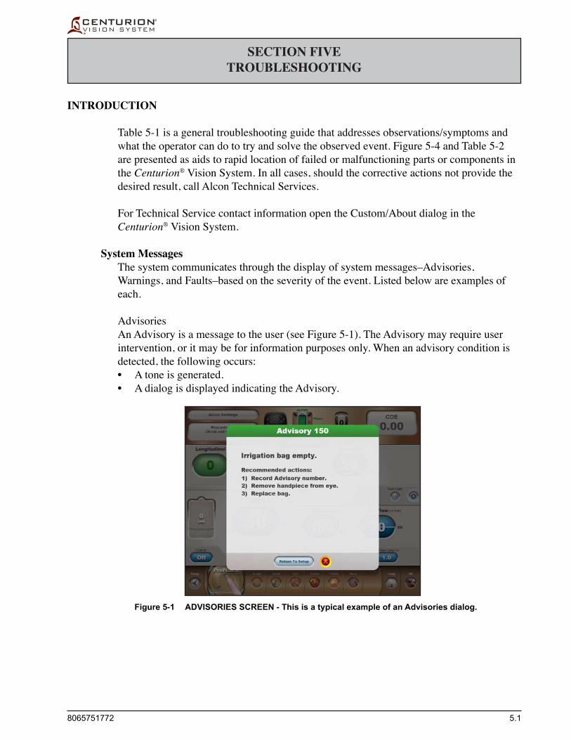
8065751772 5.1
INTRODUCTION
Table 5-1 is a general troubleshooting guide that addresses observations/symptoms and what the operator can do to try and solve the observed event. Figure 5-4 and Table 5-2 are presented as aids to rapid location of failed or malfunctioning parts or components in the Centurion® Vision System. In all cases, should the corrective actions not provide the desired result, call Alcon Technical Services.
For Technical Service contact information open the Custom/About dialog in the Centurion® Vision System.
System Messages The system communicates through the display of system messages–Advisories,
Warnings, and Faults–based on the severity of the event. Listed below are examples of each.
Advisories An Advisory is a message to the user (see Figure 5-1). The Advisory may require user
intervention, or it may be for information purposes only. When an advisory condition is detected, the following occurs:
• Atoneisgenerated. • AdialogisdisplayedindicatingtheAdvisory.
SECTION FIVETROUBLESHOOTING
Figure 5-1 ADVISORIES SCREEN - This is a typical example of an Advisories dialog.

5.2 8065751772
Figure 5-2 WARNINGS SCREEN - This is a typical example of a Warnings dialog.
Warnings Warnings are generated to indicate a non-system fault (see Figure 5-2) that is isolated and
does not affect the whole system. When a Warning is detected, the following occurs: • Atoneisgenerated. • AdialogisdisplayedindicatingtheWarning. • Affectedmechanismsareplacedinasafestate–thefunctionoftheaffected
mechanism is not available. • Ifdesired,continuewithlimitedfunctionality.
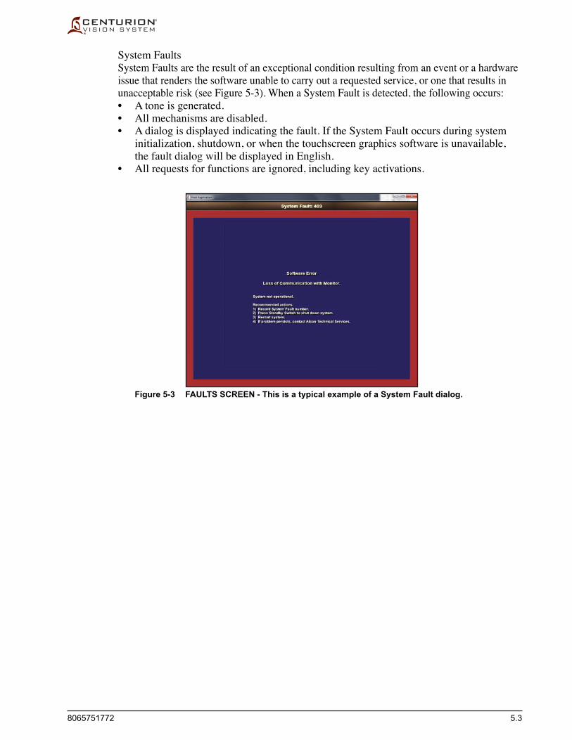
8065751772 5.3
Figure 5-3 FAULTS SCREEN - This is a typical example of a System Fault dialog.
System Faults System Faults are the result of an exceptional condition resulting from an event or a hardware
issue that renders the software unable to carry out a requested service, or one that results in unacceptable risk (see Figure 5-3). When a System Fault is detected, the following occurs:
• Atoneisgenerated. • Allmechanismsaredisabled. • Adialogisdisplayedindicatingthefault.IftheSystemFaultoccursduringsystem
initialization, shutdown, or when the touchscreen graphics software is unavailable, the fault dialog will be displayed in English.
• Allrequestsforfunctionsareignored,includingkeyactivations.
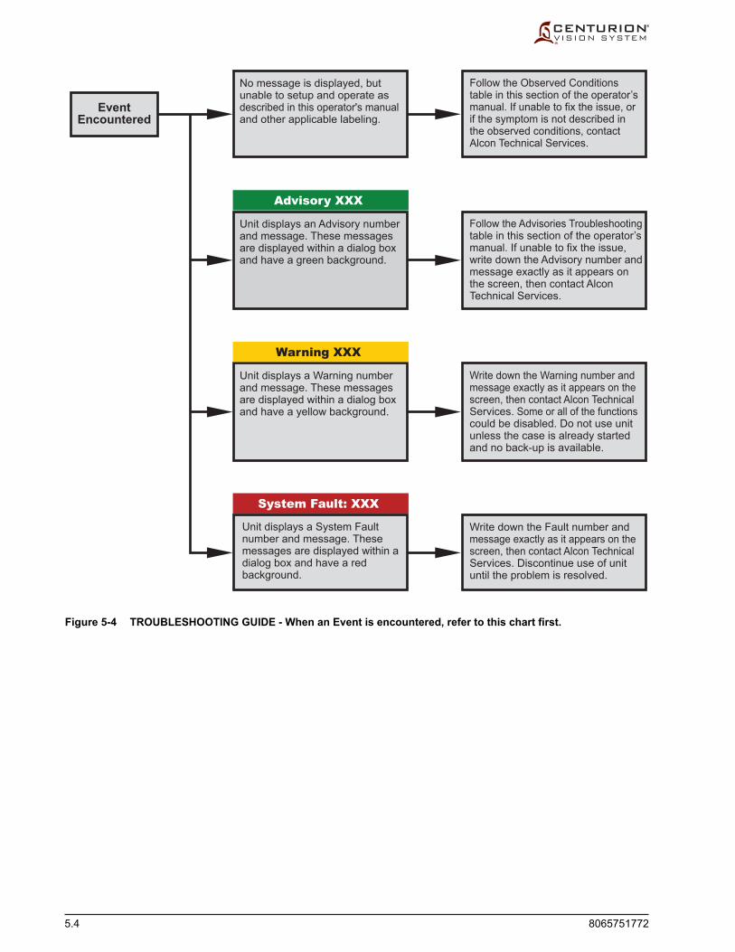
5.4 8065751772
Figure 5-4 TROUBLESHOOTING GUIDE - When an Event is encountered, refer to this chart first.
EventEncountered
Advisory XXX
Warning XXX
System Fault: XXX
Unit displays a System Faultnumber and message. Thesemessages are displayed within adialog box and have a redbackground.
Write down the Fault number andmessage exactly as it appears on thescreen, then contact Alcon TechnicalServices. Discontinue use of unituntil the problem is resolved.
Follow the Observed Conditionstable in this section of the operator’smanual. If unable to fix the issue, orif the symptom is not described inthe observed conditions, contactAlcon Technical Services.
Follow the Advisories Troubleshootingtable in this section of the operator’smanual. If unable to fix the issue,write down the Advisory number andmessage exactly as it appears onthe screen, then contact AlconTechnical Services.
No message is displayed, butunable to setup and operate asdescribed in this operator's manualand other applicable labeling.
Unit displays an Advisory numberand message. These messagesare displayed within a dialog boxand have a green background.
Unit displays a Warning numberand message. These messagesare displayed within a dialog boxand have a yellow background.
Write down the Warning number andmessage exactly as it appears on thescreen, then contact Alcon TechnicalServices. Some or all of the functionscould be disabled. Do not use unitunless the case is already startedand no back-up is available.

8065751772 5.5
System does not power-up.
Gravity Fluidics - Test chamber does not fill. There is insufficient irrigation.
Active Fluidics™ System - Test chamber does not fill. There is insufficient irrigation.
Gravity Fluidics - Vacuum check failure.
Active Fluidics™ System - Vacuum check failure.
1. Main power switch in OFF position.
2. Blown power fuse.
1. Restriction to irrigation inflow.
2. Bottle too low or handpiece too high.
3. Drip chamber not adequately filled with fluid.
4. Clogged handpiece or tips.
5. Faulty FMS.
1. Restriction to irrigation inflow.
2. Clogged handpiece or tips.
3. FMS.
1. Improper FMS insertion.
2. IRR and ASP fittings are not con-nected together securely.
3. Drip chamber not 2/3 to 3/4 full.
4. Test chamber not on handpiece, or not secured tightly onto handpiece.
5. Priming with HP attached.
6. Cracked blue luer fitting.
7. Faulty FMS.
1. Improper FMS insertion.
2. IRR and ASP fittings are not con-nected together securely.
3. Test chamber not on handpiece, or not secured tightly onto handpiece.
4. Priming with HP attached.
5. Cracked blue luer fitting.
6. Faulty FMS.
1. Turn main power switch near power cord to ON position.
2. Replace power fuse near power cord.
1. Check for kinks in irrigation line or twisted infusion sleeve.
2. Put bottle at 78 cm and put handpiece at patient eye level.
3. Squeeze drip chamber until 2/3 to 3/4 full.
4. Check handpiece and tips.
5. Replace FMS.
1. Check for kinks in irrigation line or twisted infusion sleeve.
2. Check handpiece and tips.
3. Replace FMS.
1. Reinsert FMS.
2. Ensure both fittings are tightly con-nected together.
3. Flush irrigation line and fill drip cham-ber halfway using Fill button in Setup mode. Reprime.
4. Secure test chamber tightly onto handpiece.
5. Remove HP, then connect blue and white luer fittings together.
6. Check fitting and replace FMS as necessary.
7. Replace FMS.
1. Reinsert FMS.
2. Ensure both fittings are tightly con-nected together.
3. Secure test chamber tightly onto handpiece.
4. Remove HP, then connect blue and white luer fittings together.
5. Check fitting and replace FMS as necessary.
6. Replace FMS.
SYMPTOM PROBABLE CAUSE CORRECTIVE ACTION
Table 5-1 OBSERVED CONDITIONS - Listed in this table are observed conditions that may be presented to the user. The observed Symptom is followed by the Probable Cause and its Corrective Action.
OBSERVED CONDITIONS

5.6 8065751772
SYMPTOM PROBABLE CAUSE CORRECTIVE ACTION
Gravity Fluidics - Vent test failure or vacuum and vent check failure.
Active Fluidics™ System - Vent test failure or vacuum and vent check failure.
Prime Complete / Test Handpiece Failed.
Test Handpiece Failed: Loose Tip.
Test Handpiece Failed: Tuning in Air.
Gravity Fluidics - Test chamber collapses after tuning completed—does not refill.
Active Fluidics™ System - Test chamber collapses after tuning completed—does not refill.
1. Restriction in irrigation or aspiration lines.
2. Machine insufficiently primed.
3. Faulty FMS.
1. Restriction in irrigation or aspiration lines.
2. Machine insufficiently primed.
3. Faulty FMS.
1. Faulty tip.
2. Faulty handpiece connector.
3. Bad connector port.
4. Faulty handpiece.
5. Other.
1. Loose tip.
2. Bad tip.
3. Bad connector port.
Attempted to tune tips in presence of air.
1. Clogged handpiece or tips.
2. Restriction to irrigation flow.
3. Wrong sleeve on tip.
1. Clogged handpiece or tips.
2. Restriction to irrigation flow.
3. Wrong sleeve on tip.
1. Check kinked irrigation or aspiration lines or twisted tip cap sleeve.
2. Press Test to reprime.
3. Reinsert FMS. Replace FMS if prob-lem persists.
1. Check kinked irrigation or aspiration lines or twisted tip cap sleeve.
2. Press Test to reprime.
3. Reinsert FMS. Replace FMS if prob-lem persists.
1. Remove tip and replace if faulty. Retighten. Retest.
2. Unplug, reinsert into port, retest. 3.Connect handpiece to other port and
retune.
4. Replace handpiece. Retest.
5. Record the failed code number and contact Alcon Technical Services Department.
1. Tighten tip and retune.
2. Replace tip and retune.
3. Connect handpiece to other port and retune.
Fill test chamber completely. Retune.
1. Check handpiece and tips irrigation flow.
2. Check for kinks in irrigation line or twisted infusion sleeve.
3. Check for proper sleeve and tip size.
1. Check handpiece and tips irrigation flow.
2. Check for kinks in irrigation line or twisted infusion sleeve.
3. Check for proper sleeve and tip size.
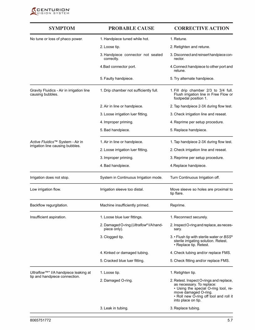
8065751772 5.7
SYMPTOM PROBABLE CAUSE CORRECTIVE ACTION
No tune or loss of phaco power.
Gravity Fluidics - Air in irrigation line causing bubbles.
Active Fluidics™ System - Air in irrigation line causing bubbles.
Irrigation does not stop.
Low irrigation flow.
Backflow regurgitation.
Insufficient aspiration.
Ultraflow™* I/A handpiece leaking at tip and handpiece connection.
1. Handpiece tuned while hot.
2. Loose tip.
3. Handpiece connector not seated correctly.
4.Bad connector port.
5. Faulty handpiece.
1. Drip chamber not sufficiently full.
2. Air in line or handpiece.
3. Loose irrigation luer fitting.
4. Improper priming.
5. Bad handpiece.
1. Air in line or handpiece.
2. Loose irrigation luer fitting.
3. Improper priming.
4. Bad handpiece.
System in Continuous Irrigation mode.
Irrigation sleeve too distal.
Machine insufficiently primed.
1. Loose blue luer fittings.
2. Damaged O-ring (Ultraflow® I/A hand-piece only).
3. Clogged tip.
4. Kinked or damaged tubing.
5. Cracked blue luer fitting.
1. Loose tip.
2. Damaged O-ring.
3. Leak in tubing.
1. Retune.
2. Retighten and retune.
3. Disconnect and reinsert handpiece con-nector.
4.Connect handpiece to other port and retune.
5. Try alternate handpiece.
1. Fill drip chamber 2/3 to 3/4 full. Flush irrigation line in Free Flow or footpedal position 1.
2. Tap handpiece 2-3X during flow test.
3. Check irrigation line and reseat.
4. Reprime per setup procedure.
5. Replace handpiece.
1. Tap handpiece 2-3X during flow test.
2. Check irrigation line and reseat.
3. Reprime per setup procedure.
4.Replace handpiece.
Turn Continuous Irrigation off.
Move sleeve so holes are proximal to tip flare.
Reprime.
1. Reconnect securely.
2. Inspect O-ring and replace, as neces-sary.
3. • Flush tip with sterile water or BSS® sterile irrigating solution. Retest.
• Replace tip. Retest.
4. Check tubing and/or replace FMS.
5. Check fitting and/or replace FMS.
1. Retighten tip.
2. Retest. Inspect O-rings and replace, as neces sary. To replace:
• Using the special O-ring tool, re-move damaged O-ring.
• Roll new O-ring off tool and roll it into place on tip.
3. Replace tubing.

5.8 8065751772
SYMPTOM PROBABLE CAUSE CORRECTIVE ACTION
“Calibration failed. Vitrectomy cut rate will be limited to 800 cpm” Advisory is displayed at power up.
Ineffective or poor Vit cutting.
Ant Vit probe does not work at all (no movement).
Gravity Fluidics - IV pole does not retract completely upon shutdown.
Remote control does not work.
Cabled Footswitch - Footpedal not responding properly.
Wireless Footswitch - Footpedal not responding properly.
Internal pneumatics valve calibration has failed.
1. Port not closing fully as the inner cutter moves.
2. Kinked, damaged or loose actuation tubing.
3. Faulty probe (activated in air instead of fluid).
1. An actuation line filling with BSS® fluid due to improper setup.
2. Faulty probe.
System error.
1. Remote control and system set on different channels.
2. Batteries discharged.
1. Footpedal was pressed when system was powered up, or footpedal was pressed while plugging in footswitch.
2. Footswitch connector not seated properly.
3. Debris or BSS® solution residue under rear section of treadle.
4. Console malfunction.
5. Faulty footswitch.
1. Footpedal was pressed down when system was powered up
2. Debris or BSS® solution residue under rear section of treadle.
3. Wireless communications not work-ing properly.
4. Faulty footswitch.
Continue vitrectomy procedure with lim-ited cut rate and contact Alcon Technical Services Department.
1. Reduce cutting speed until port closes completely.
2. Check for damaged or kinked tubing; straighten if necessary. Tighten any loose luer fittings. Replace probe if visual inspection shows any dam-aged components.
3. Replace probe.
1. Check for correct tubing connections, then replace probe.
2. Replace probe.
Turn system on, wait until system powers up, then turn system off using Standby power switch located on upper rear panel.
1. Verify system channel selection and remote channel select are set to same channel (A, B, C, D, E, or F).
2. Replace batteries in remote control.
1. Release footpedal and power off system. Make sure footswitch is properly connected to system, and turn power back on, with footpedal in full up position.
2. Disconnect and reconnect footswitch cable connector.
3. Clean and remove debris.
4. Disconnect and reconnect footswitch cable connector.
5. Replace footswitch.
1. Release footpedal and power off system. Turn power back on, with footpedal in full up position.
2. Clean and remove debris.
3. Connect footswitch to console with cable.
4. Replace footswitch.

8065751772 5.9
1. Verify proper insertion of footswitch cable connector (while footpedal/treadle is in full up position).
2. Disconnect and reconnect footswitch cable connector.
3. Replace footswitch.
1. Hang footswitch onto footswitch hooks on the rear of the unit for greater than 5 seconds then remove.
Carefully record all text appearing in Fault screen, on display. Press and hold Standby switch for a few seconds to turn system off, wait until screen goes dark, then turn system back on to see whether fault clears. Contact Technical Services.
Save data. U/S Occlusion settings will be removed.
1. Improperly connected or discon-nected footswitch.
2. Footswitch connector not seated properly.
3. Faulty footswitch.
1. Footswitch has not been “paired” with the console.
System Fault has several possible causes.
User restores, or selects Doctor Name that contains U/S Occlusion settings which are no longer available.
Cabled Footswitch - “Please Install Footswitch” Advisory is displayed.
Wireless Footswitch - “Please Install Footswitch” Advisory is displayed.
System Fault occurs; entire system inoperative, red screen with stop sign is displayed.
“Doctor data invalid, U/S Occlusion, Dr. XXXX” Advisory is displayed.
SYMPTOM PROBABLE CAUSE CORRECTIVE ACTION

5.10 8065751772
ADVISORIES
EVENT CODE MESSAGE DISPLAYED
Table 5-2 EVENT CODES - Listed in this table are messages shown on the Centurion® Vision System display panel when the system detects an event. The Event codes are separated between Advisories, Warnings, and Faults.
Advisory xxxActive Fluidics is not available.Recommended actions:1) Remove FMS.2) Use Gravity Fluidics.3) If condition persists, note Advisory number
and contact Alcon Technical Services.See the About Dialog for Alcon Technical Services contact information.
Advisory xxxAspiration, phaco power, and vitrectomy cutting are unavailable.Recommended actions:1) Check for irrigation path obstructions.2) Replace FMS.3) If condition persists, note Advisory number
and contact Alcon Technical Services.See the About Dialog for Alcon Technical Services contact information.
Advisory xxxIrrigation is unavailable.Recommended actions:1) Replace FMS.2) If condition persists, note Advisory number
and contact Alcon Technical Services.See the About Dialog for Alcon Technical Services contact information.
Advisory xxxFMS calibration failed.Recommended actions:1) Reinsert FMS.2) If condition persists, replace FMS.
Advisory xxxVacuum check failed.Recommended actions:1) Check luer fittings and reprime.2) If condition persists, reinsert or replace FMS.3) If condition persists, note Advisory number
and contact Alcon Technical Services.See the About Dialog for Alcon Technical Services contact information.
Advisory xxxFlow obstruction.Recommended actions:1) Check handpiece free flow.2) If condition persists, replace phaco tip or
sleeve.3) If condition persists, note Advisory number
and contact Alcon Technical Services.See the About Dialog for Alcon Technical Services contact information.
157
158
159
160
161-167
168
100 - Fluidics Mechanism
Warning xxxFluidics not available.Recommended actions:1) If in surgery, stabilize the eye then restart
system.2) If condition persists after restart, note
Warning number and contact Alcon Technical Services.
See the About Dialog for Alcon Technical Services contact information.
Advisory xxxIrrigation bag empty.Recommended actions:1) Release footswitch treadle.2) Remove handpiece from eye.3) Replace bag.
Advisory xxxIrrigation bag empty.Recommended actions:1) Replace bag.
Advisory xxxBag bay door open.Recommended actions:1) Close door.2) Proceed with surgery.Alternate actions:1) Remove handpiece from eye.2) Press ‘Return to Setup Screen’.
Advisory xxxBag bay door was opened.Recommended actions:1) Close bag door.2) Repeat operation.
Advisory xxxIrrigation bag is almost empty.Recommended actions:1) Replace bag.
Advisory xxxActive Fluidics is not available.Recommended actions:1) Remove FMS.2) Use Gravity Fluidics.3) If condition persists, note Advisory number
and contact Alcon Technical Services.See the About Dialog for Alcon Technical Services contact information.
101-149
150
151
153
154
155
156
EVENT CODE MESSAGE DISPLAYED

8065751772 5.11
ADVISORIES
169
170
171
179
180
181
182
190
Advisory xxxIrrigation pressure is low.Recommended actions:1) Check bottle fluid level.Alternate actions:1) Check for kinked lines or loose fittings.
Advisory xxxReflux terminated. Reflux fluid volume depleted. Reflux will be unavailable until fluid is aspirated.Recommended actions:1) Aspirate fluid.
Advisory xxxDrain bag is full.Recommended actions:1) Replace FMS.
Advisory xxxFMS barcode invalid.Recommended actions:1) Reinsert FMS2) If condition persists, replace FMS.
Advisory xxxInvalid FMS ID.Recommended actions:1) Reinsert FMS.2) If condition persists, replace FMS.
Advisory xxxFMS calibration failed.Recommended actions:1) Reinsert FMS.2) If condition persists, replace FMS.3) If condition persists, restart system.4) If condition persists, note Advisory number
and contact Alcon Technical Services.See the About Dialog for Alcon Technical Services contact information.
Advisory xxxActive Fluidics is not available.Recommended actions:1) Remove FMS.2) Use Gravity Fluidics.3) If condition persists, note Advisory number
and contact Alcon Technical Services.See the About Dialog for Alcon Technical Services contact information.
EVENT CODE MESSAGE DISPLAYED
EVENT CODE MESSAGE DISPLAYED
191
201-249
250
254-255
256-266
268
Advisory xxxActive Fluidics is not available.Recommended actions:1) Remove FMS.2) Use Gravity Fluidics.3) If condition persists, note Advisory number
and contact Alcon Technical Services.See the About Dialog for Alcon Technical Services contact information.
200 - Ultrasonics Mechanism
Warning xxxUltrasound not available.Recommended actions:1) If in surgery, stabilize the eye then restart
system.2) If condition persists after restart, note
Warning number and contact Alcon Technical Services.
See the About Dialog for Alcon Technical Services contact information.
Advisory xxxTesting in air.Recommended actions:1) Fill test chamber completely.2) Re-test handpiece.Alternate actions:1) Connect handpiece to other port and re-test.2) If condition persists, replace handpiece.3) If condition persists, note Advisory number
and contact Alcon Technical Services.See the About Dialog for Alcon Technical Services contact information.
Advisory xxxLoose tip.Recommended actions:1) Tighten or replace tip.2) Re-test handpiece.Alternate actions:1) Connect handpiece to other port.2) Re-test handpiece.3) If condition persists, replace handpiece.
Advisory xxxHandpiece test failed.Recommended actions:1) Remove and reconnect handpiece.2) If condition persists, try other port.3) If condition persists, replace handpiece.4) If condition persists and in surgery, stabilize
the eye then restart system.5) If condition persists after restart, note
Advisory number and contact Alcon Technical Services.
See the About Dialog for Alcon Technical Services contact information.
Advisory xxxHandpiece test failed.Recommended actions:1) Press ‘Return to Setup Screen’.2) Re-test handpiece.

5.12 8065751772
269
270-273
274
277
278
279-280
Advisory xxxHandpiece test failed.Recommended actions:1) Re-test handpiece.
Advisory xxxHandpiece fault detected.Recommended actions:1) Connect handpiece to other port.2) Re-test handpiece.3) If condition persists, replace handpiece.4) If condition persists and in surgery, stabilize
the eye then restart system.5) If condition persists after restart, note
Advisory number and contact Alcon Technical Services.
See the About Dialog for Alcon Technical Services contact information.
Advisory xxxUltrasound error.Recommended actions:1) Release footswitch treadle and retry.2) If condition persists and in surgery, stabilize
the eye then restart system.3) If condition persists after restart, note
Advisory number and contact Alcon Technical Services.
See the About Dialog for Alcon Technical Services contact information.
Advisory xxxHandpiece disconnected while applying U/S power.Recommended actions:1) Release footswitch treadle.2) Insert and test handpiece.
Advisory xxxHandpiece fault detected.Recommended actions:1) Connect handpiece to other port.2) Re-test handpiece.3) If condition persists, replace handpiece.4) If condition persists and in surgery, stabilize
the eye then restart system.5) If condition persists after restart, note
Advisory number and contact Alcon Technical Services.
See the About Dialog for Alcon Technical Services contact information.
Advisory xxxUnknown handpiece detected.Recommended actions:1) Remove and inspect cable connector for
debris.2) Verify handpiece compatibility.3) If condition persists, connect to other port.4) If condition persists, replace handpiece.5) If condition persists and in surgery, stabilize
the eye then restart system.6) If condition persists after restart, note Advisory
number and contact Alcon Technical Services.See the About Dialog for Alcon Technical Services contact information.
290
291
293
301-349
350
Advisory xxxUltrasound error.Recommended actions:1) Release footswitch treadle and retry.2) If condition persists and in surgery, stabilize
the eye then restart system.3) If condition persists after restart, note
Advisory number and contact Alcon Technical Services.
See the About Dialog for Alcon Technical Services contact information.
Advisory xxxUltrasound error.Recommended actions:1) Release footswitch treadle, wait 10 seconds,
then retry.2) If condition persists and in surgery, stabilize
the eye then restart system.3) If condition persists after restart, note
Advisory number and contact Alcon Technical Services.
See the About Dialog for Alcon Technical Services contact information.
Advisory xxxUltrasound error.Recommended actions:1) Release footswitch treadle and retry.2) If condition persists and in surgery, stabilize
the eye then restart system.3) If condition persists after restart, note
Advisory number and contact Alcon Technical Services.
See the About Dialog for Alcon Technical Services contact information.
300 - Footswitch Mechanism
Warning xxxSurgical functionality not available.Recommended actions:1) If in surgery, stabilize the eye then restart
system.2) If condition persists after restart, note
Warning number and contact Alcon Technical Services.
See the About Dialog for Alcon Technical Services contact information.
Advisory xxxFootswitch failure detected.Recommended actions:1) Inspect footswitch, clean under rear
section of treadle and remove debris if present. (Reference Maintenance section of Operator’s Manual.)
2) Inspect and reconnect footswitch connector.3) Ensure treadle is not depressed then reset
footswitch.4) If condition persists, replace footswitch.5) If condition persists, note Advisory number
and contact Alcon Technical Services.See the About Dialog for Alcon Technical Services contact information.
ADVISORIES
EVENT CODE MESSAGE DISPLAYED
EVENT CODE MESSAGE DISPLAYED

8065751772 5.13
ADVISORIES
351
352
358-359
360
361
362
Advisory xxxFootswitch failure detected.Recommended actions:1) Inspect and reset footswitch.2) If condition persists, replace footswitch.3) If condition persists, note Advisory number
and contact Alcon Technical Services.See the About Dialog for Alcon Technical Services contact information.
Advisory xxxFootswitch failure.Recommended actions:1) Inspect and reconnect footswitch connector.2) If condition persists, replace footswitch.3) If condition persists, note Advisory number
and contact Alcon Technical Services.See the About Dialog for Alcon Technical Services contact information.
Advisory xxxFootswitch charging while cradled is unavailable.Recommended actions:1) Cable the footswitch if charging is desired.2) If condition persists after restart, note
Advisory number and contact Alcon Technical Services.
See the About Dialog for Alcon Technical Services contact information.
Advisory xxxFootswitch battery is low.Recommended actions:1) Cradle the footswitch after surgical cases
have been completed.2) If condition persists, note Advisory number
and contact Alcon Technical Services.See the About Dialog for Alcon Technical Services contact information.
Advisory xxxFootswitch battery is critically low. Footswitch functionality may be lost unexpectedly.Recommended actions:1) Connect footswitch cable to console.2) Cradle the footswitch after surgical cases
have been completed.3) If condition persists, note Advisory number
and contact Alcon Technical Services.See the About Dialog for Alcon Technical Services contact information.
Advisory xxxFootswitch version not supported.Recommended actions:1) Replace footswitch.2) If condition persists, note Advisory and
contact Alcon Technical Services.See the About Dialog for Alcon Technical Services contact information.
EVENT CODE MESSAGE DISPLAYED
EVENT CODE MESSAGE DISPLAYED
363
364-365
366
367-368
369
370
371
372-376
377-380
381-382
Advisory xxxFootswitch communication lost.Recommended actions:1) Release footswitch treadle.2) If footswitch is wireless, move footswitch and
console closer, or eliminate obstruction.3) If footswitch is cabled, replace cable.4) If condition persists, replace footswitch.
Advisory xxxFootswitch failure detected.Recommended actions:1) Release footswitch treadle.2) If condition persists, replace footswitch.
Advisory xxxFootswitch detent failure detected. Detent vibration will not be provided.Recommended actions:1) Release footswitch treadle.2) Proceed with surgery.3) If condition persists after restart, replace
footswitch.
Advisory xxxFootswitch failure detected.Recommended actions:1) Release footswitch treadle.2) If condition persists, replace footswitch.
Advisory xxxFootswitch wireless operation unavailable.Recommended actions:1) Do not disconnect footswitch cable.2) If condition persists, replace footswitch.
Advisory xxxFootswitch failure detected.Recommended actions:1) Release footswitch treadle.2) If condition persists, replace footswitch.
Advisory xxxFootswitch failure detected.Recommended actions:1) Release footswitch treadle.2) If condition persists, replace footswitch.
Advisory xxxFootswitch failure detected.Recommended actions:1) Release footswitch treadle and buttons.2) Place footswitch in horizontal position.3) If condition persists, replace footswitch.
Advisory xxxFootswitch failure detected.Recommended actions:1) Release footswitch treadle.2) If condition persists, replace footswitch.
Advisory xxxFootswitch failure detected.Recommended actions:1) Connect footswitch cable to console.2) If condition persists, replace footswitch.
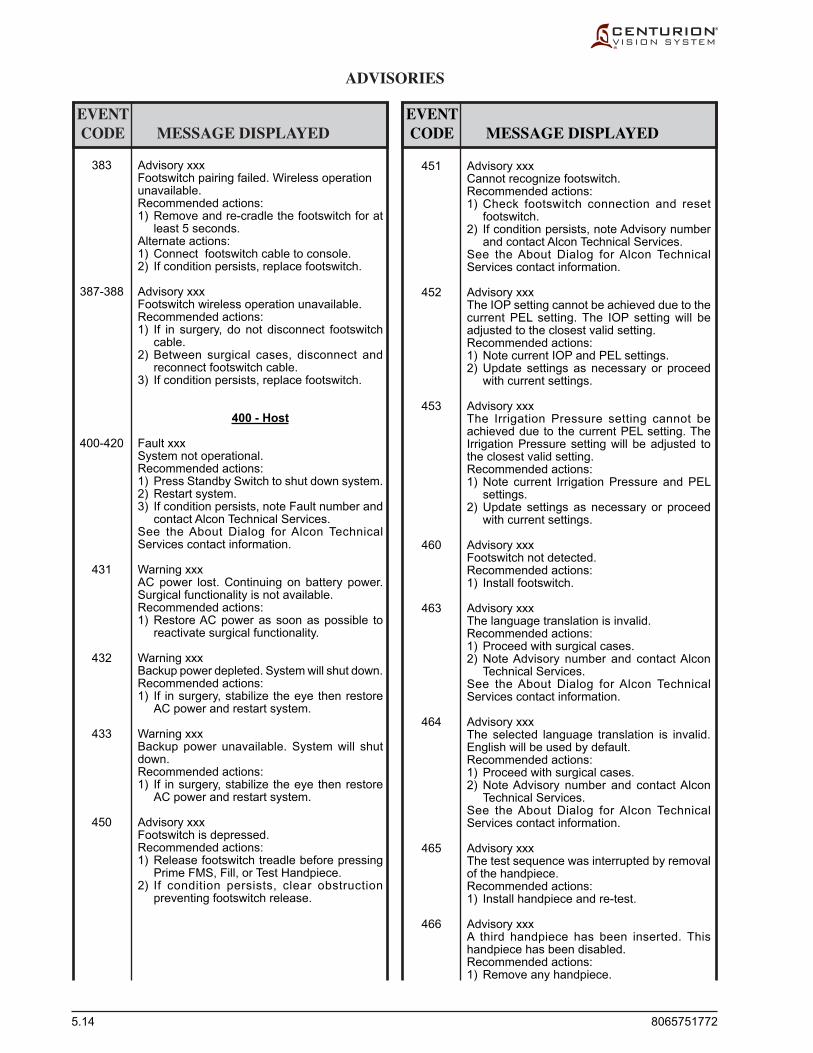
5.14 8065751772
ADVISORIES
383
387-388
400-420
431
432
433
450
Advisory xxxFootswitch pairing failed. Wireless operation unavailable.Recommended actions:1) Remove and re-cradle the footswitch for at
least 5 seconds.Alternate actions:1) Connect footswitch cable to console.2) If condition persists, replace footswitch.
Advisory xxxFootswitch wireless operation unavailable.Recommended actions:1) If in surgery, do not disconnect footswitch
cable.2) Between surgical cases, disconnect and
reconnect footswitch cable.3) If condition persists, replace footswitch.
400 - Host
Fault xxxSystem not operational.Recommended actions:1) Press Standby Switch to shut down system.2) Restart system.3) If condition persists, note Fault number and
contact Alcon Technical Services.See the About Dialog for Alcon Technical Services contact information.
Warning xxxAC power lost. Continuing on battery power. Surgical functionality is not available.Recommended actions:1) Restore AC power as soon as possible to
reactivate surgical functionality.
Warning xxxBackup power depleted. System will shut down.Recommended actions:1) If in surgery, stabilize the eye then restore
AC power and restart system.
Warning xxxBackup power unavailable. System will shut down.Recommended actions:1) If in surgery, stabilize the eye then restore
AC power and restart system.
Advisory xxxFootswitch is depressed.Recommended actions:1) Release footswitch treadle before pressing
Prime FMS, Fill, or Test Handpiece.2) If condition persists, clear obstruction
preventing footswitch release.
EVENT CODE MESSAGE DISPLAYED
EVENT CODE MESSAGE DISPLAYED
451
452
453
460
463
464
465
466
Advisory xxxCannot recognize footswitch.Recommended actions:1) Check footswitch connection and reset
footswitch.2) If condition persists, note Advisory number
and contact Alcon Technical Services.See the About Dialog for Alcon Technical Services contact information.
Advisory xxxThe IOP setting cannot be achieved due to the current PEL setting. The IOP setting will be adjusted to the closest valid setting.Recommended actions:1) Note current IOP and PEL settings.2) Update settings as necessary or proceed
with current settings.
Advisory xxxThe Irrigation Pressure setting cannot be achieved due to the current PEL setting. The Irrigation Pressure setting will be adjusted to the closest valid setting.Recommended actions:1) Note current Irrigation Pressure and PEL
settings.2) Update settings as necessary or proceed
with current settings.
Advisory xxxFootswitch not detected.Recommended actions:1) Install footswitch.
Advisory xxxThe language translation is invalid.Recommended actions:1) Proceed with surgical cases.2) Note Advisory number and contact Alcon
Technical Services.See the About Dialog for Alcon Technical Services contact information.
Advisory xxxThe selected language translation is invalid. English will be used by default.Recommended actions:1) Proceed with surgical cases.2) Note Advisory number and contact Alcon
Technical Services.See the About Dialog for Alcon Technical Services contact information.
Advisory xxxThe test sequence was interrupted by removal of the handpiece.Recommended actions:1) Install handpiece and re-test.
Advisory xxxA third handpiece has been inserted. This handpiece has been disabled.Recommended actions:1) Remove any handpiece.
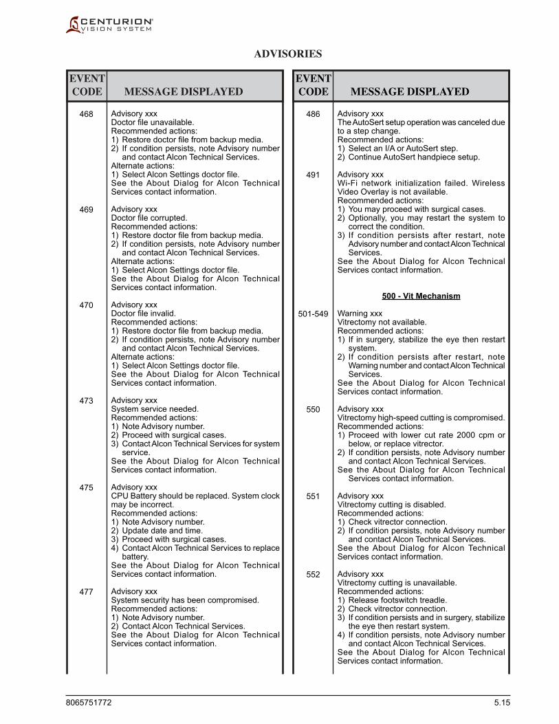
8065751772 5.15
ADVISORIES
468
469
470
473
475
477
Advisory xxxDoctor file unavailable.Recommended actions:1) Restore doctor file from backup media.2) If condition persists, note Advisory number
and contact Alcon Technical Services.Alternate actions:1) Select Alcon Settings doctor file.See the About Dialog for Alcon Technical Services contact information.
Advisory xxxDoctor file corrupted.Recommended actions:1) Restore doctor file from backup media.2) If condition persists, note Advisory number
and contact Alcon Technical Services.Alternate actions:1) Select Alcon Settings doctor file.See the About Dialog for Alcon Technical Services contact information.
Advisory xxxDoctor file invalid.Recommended actions:1) Restore doctor file from backup media.2) If condition persists, note Advisory number
and contact Alcon Technical Services.Alternate actions:1) Select Alcon Settings doctor file.See the About Dialog for Alcon Technical Services contact information.
Advisory xxxSystem service needed.Recommended actions:1) Note Advisory number.2) Proceed with surgical cases.3) Contact Alcon Technical Services for system
service.See the About Dialog for Alcon Technical Services contact information.
Advisory xxxCPU Battery should be replaced. System clock may be incorrect.Recommended actions:1) Note Advisory number.2) Update date and time.3) Proceed with surgical cases.4) Contact Alcon Technical Services to replace
battery.See the About Dialog for Alcon Technical Services contact information.
Advisory xxxSystem security has been compromised.Recommended actions:1) Note Advisory number.2) Contact Alcon Technical Services.See the About Dialog for Alcon Technical Services contact information.
EVENT CODE MESSAGE DISPLAYED
EVENT CODE MESSAGE DISPLAYED
486
491
501-549
550
551
552
Advisory xxxThe AutoSert setup operation was canceled due to a step change.Recommended actions:1) Select an I/A or AutoSert step.2) Continue AutoSert handpiece setup.
Advisory xxxWi-Fi network initialization failed. Wireless Video Overlay is not available.Recommended actions:1) You may proceed with surgical cases.2) Optionally, you may restart the system to
correct the condition.3) If condition persists after restart, note
Advisory number and contact Alcon Technical Services.
See the About Dialog for Alcon Technical Services contact information.
500 - Vit Mechanism
Warning xxxVitrectomy not available.Recommended actions:1) If in surgery, stabilize the eye then restart
system.2) If condition persists after restart, note
Warning number and contact Alcon Technical Services.
See the About Dialog for Alcon Technical Services contact information.
Advisory xxxVitrectomy high-speed cutting is compromised.Recommended actions:1) Proceed with lower cut rate 2000 cpm or
below, or replace vitrector.2) If condition persists, note Advisory number
and contact Alcon Technical Services.See the About Dialog for Alcon Technical
Services contact information.
Advisory xxxVitrectomy cutting is disabled.Recommended actions:1) Check vitrector connection.2) If condition persists, note Advisory number
and contact Alcon Technical Services.See the About Dialog for Alcon Technical Services contact information.
Advisory xxxVitrectomy cutting is unavailable.Recommended actions:1) Release footswitch treadle.2) Check vitrector connection.3) If condition persists and in surgery, stabilize
the eye then restart system.4) If condition persists, note Advisory number
and contact Alcon Technical Services.See the About Dialog for Alcon Technical Services contact information.

5.16 8065751772
600 - Coag Mechanism
Warning xxxCoagulation is not available.Recommended actions:1) If in surgery, stabilize the eye then restart
system.2) If condition persists after restart, note
Warning number and contact Alcon Technical Services.
See the About Dialog for Alcon Technical Services contact information.
Advisory xxxCoagulation is not available.Recommended actions:1) If condition persists and in surgery, stabilize
the eye then restart system.2) If condition persists, note Advisory number
and contact Alcon Technical Services.See the About Dialog for Alcon Technical Services contact information.
700 - IV Pole Mechanism
Warning xxxIV Pole not available.Recommended actions:1) If in surgery, stabilize the eye then restart
system.2) If condition persists after restart, note
Warning number and contact Alcon Technical Services.
See the About Dialog for Alcon Technical Services contact information.
Advisory xxxIV Pole jammed. Pole may not have achieved desired height.Recommended actions:1) Check for external obstacles.2) If condition persists and in surgery, stabilize
the eye then restart system.3) If condition persists, note advisory number
and contact Alcon Technical Services.See the About Dialog for Alcon Technical Services contact information.
800 - IOL Mechanism
Warning xxxAutoSert not available.Recommended actions:1) If in surgery, stabilize the eye then restart
system.2) If condition persists after restart, note
Warning number and contact Alcon Technical Services.
See the About Dialog for Alcon Technical Services contact information.
601-649
650
701-749
750
801-849
860
888
889
890
891
Advisory xxxTwo AutoSert Handpieces detected.Recommended actions:1) Remove one AutoSert Handpiece and
proceed.
Advisory xxxAutoSert error occurred.Recommended actions:1) Retry AutoSert operation.2) If condition persists, replace AutoSert
Handpiece.3) If condition persists and in surgery, stabilize
the eye then restart system.4) If condition persists after restart, note
Advisory number and contact Alcon Technical Services.
See the About Dialog for Alcon Technical Services contact information.
Advisory xxxHandpiece fault detected.Recommended actions:1) Replace AutoSert handpiece.2) If condition persists and in surgery, stabilize
the eye then restart system.3) If condition persists after restart, note
Advisory number and contact Alcon Technical Services.
See the About Dialog for Alcon Technical Services contact information.
Advisory xxxAutoSert error occurred.Recommended actions:1) Release footswitch treadle and retry.2) If condition persists, replace AutoSert
handpiece.3) If condition persists and in surgery, stabilize
the eye then restart system.4) If condition persists after restart, note
Advisory number and contact Alcon Technical Services.
See the About Dialog for Alcon Technical Services contact information.
Advisory xxxAutoSert handpiece impeded.Recommended actions:1) Release footswitch treadle and retry.2) If condition persists, replace AutoSert
handpiece.3) If condition persists and in surgery, stabilize
the eye then restart system.4) If condition persists after restart, note
Advisory number and contact Alcon Technical Services.
See the About Dialog for Alcon Technical Services contact information.
ADVISORIES
EVENT CODE MESSAGE DISPLAYED
EVENT CODE MESSAGE DISPLAYED

8065751772 5.17
Advisory xxxHandpiece fault detected.Recommended actions:1) Reinsert handpiece cable connector.2) If condition persists, replace AutoSert
Handpiece.3) If condition persists and in surgery, stabilize
the eye then restart system.4) If condition persists after restart, note
Advisory number and contact Alcon Technical Services.
See the About Dialog for Alcon Technical Services contact information.
Advisory xxxAutoSert handpiece calibration failed.Recommended actions:1) Replace AutoSert Handpiece.2) If condition persists and in surgery, stabilize
the eye then restart system.3) If condition persists after restart, note
Advisory number and contact Alcon Technical Services.
See the About Dialog for Alcon Technical Services contact information.
Advisory xxxHandpiece must be in fully retracted position prior to autoclave.Recommended actions:1) Reinsert AutoSert Handpiece.
Advisory xxxHandpiece fault detected.Recommended actions:1) Replace AutoSert Handpiece.2) If condition persists and in surgery, stabilize
the eye then restart system.3) If condition persists after restart, note
Advisory number and contact Alcon Technical Services.
See the About Dialog for Alcon Technical Services contact information.
892
893
894
895
897
900 - Pump Mechanism
Warning xxxVitrectomy not available.Recommended actions:1) If in surgery, stabilize the eye then restart
system.2) If condition persists after restart, note
Warning number and contact Alcon Technical Services.
See the About Dialog for Alcon Technical Services contact information.
Advisory xxxPump leak detected. Vitrectomy cutting may be unavailable.Recommended actions:1) Verify if vitrectomy cutter is disabled.2) If condition persists, note advisory number
and contact Alcon Technical Services.See the About Dialog for Alcon Technical Services contact information.
1000 - AutoCap Mechanism
Warning xxxCapsulotomy is not available.Recommended actions:1) If in surgery, stabilize the eye then restart
system.2) If condition persists after restart, note
Warning number and contact Alcon Technical Services.
See the About Dialog for Alcon Technical Services contact information.
Advisory xxxFootswitch is depressed.Recommended actions:1) Release footswitch treadle before enabling
Capsulotomy.
Advisory xxxICD test failed.Recommended actions:1) Re-test ICD.
Advisory xxxICD test failed.Recommended actions:1) Remove and reconnect ICD, then re-test
ICD.2) If condition persists, replace ICD.3) If condition persists and in surgery, stabilize
the eye then restart system.4) If condition persists after restart, note
Advisory number and contact Alcon Technical Services.
See the About Dialog for Alcon Technical Services contact information.
901-949
950
1001-1049
1050
1061
1062-1064
ADVISORIES
EVENT CODE MESSAGE DISPLAYED
EVENT CODE MESSAGE DISPLAYED

5.18 8065751772
ADVISORIES
EVENT CODE MESSAGE DISPLAYED
EVENT CODE MESSAGE DISPLAYED
Advisory xxxICD test failed.Recommended actions:1) Press ‘Return to Setup Screen’.2) Re-test ICD.
Advisory xxxICD failed.Recommended actions:1) Press ‘Return to Setup Screen’.2) Remove and reconnect ICD, then re-test
ICD.3) If condition persists, replace ICD.4) If condition persists and in surgery, stabilize
the eye then restart system.5) If condition persists after restart, note
Advisory number and contact Alcon Technical Services.
See the About Dialog for Alcon Technical Services contact information.
Capsulotomy is not supported.Recommended actions:1) Select a different procedure or remove the
Capsulotomy step.
1100 - Power Control Mechanism
Warning xxxMechanism power control error.Recommended actions:1) If in surgery, stabilize the eye.2) Press Standby Switch for 5 seconds to
shutdown system.3) Restart system.4) If condition persists, note Warning number
and contact Alcon Technical Services.See the About Dialog for Alcon Technical Services contact information.
Advisory xxxBackup power service needed. System will shut down immediately if AC Power is lost.Recommended actions:1) You may proceed with surgery.2) If condition persists, note Advisory number
and contact Alcon Technical Services.See the About Dialog for Alcon Technical Services contact information.
Advisory xxxBackup power temporarily unavailable. Battery is recharging. System will shut down immediately if AC Power is lost.Recommended actions:1) You may proceed with surgery.2) If condition persists, note Advisory number
and contact Alcon Technical Services.See the About Dialog for Alcon Technical Services contact information.
1065
1072-1076
1099
1101-1149
1150
1151
Advisory xxxBackup power unavailable. System will shut down immediately if AC Power is lost.Recommended actions:1) You may proceed with surgery.2) If condition persists, note Advisory number
and contact Alcon Technical Services.See the About Dialog for Alcon Technical Services contact information.
1200 - Wireless Mechanism
Warning xxxWireless features not available.1) If in surgery, stabilize the eye then restart
system.2) If condition persists after restart, note
Warning number and contact Alcon Technical Services.
See the About Dialog for Alcon Technical Services contact information.
Advisory xxxWireless channel is already in use by another Centurion console.Recommended actions:1) Open the System Settings dialog and change
the Wireless Channel.
1300 - Tone Mechanism
Warning xxxFluidics and Coagulation not available.Recommended actions:1) If in surgery, stabilize the eye then restart
system.2) If condition persists after restart, note
Warning number and contact Alcon Technical Services.
See the About Dialog for Alcon Technical Services contact information.
1400 - Operator Control Mechanism
Warning xxxFluidics not available.Recommended actions:1) If in surgery, stabilize the eye then restart
system.2) If condition persists after restart, note
Warning number and contact Alcon Technical Services.
See the About Dialog for Alcon Technical Services contact information.
1153-1156
1201-1249
1250
1301-1349
1401-1449

8065751772 5.19
ADVISORIES
EVENT CODE MESSAGE DISPLAYED
EVENT CODE MESSAGE DISPLAYED
2000-2006
2015
2100-2106
2115
2200-2206
2000 - IA Subsystem
Warning xxxFluidics, Vitrectomy, and Coagulation not available.Recommended actions:1) If in surgery, stabilize the eye then restart
system.2) If condition persists after restart, note
Warning number and contact Alcon Technical Services.
See the About Dialog for Alcon Technical Services contact information.
Warning xxxFluidics, Vitrectomy, and Coagulation not available.Recommended actions:1) Restart system.2) If condition persists after restart, note
Warning number and contact Alcon Technical Services.
See the About Dialog for Alcon Technical Services contact information.
2100 - Generator Subsystem
Ultrasonics, Capsulotomy, and AutoSert not available.Recommended actions:1) If in surgery, stabilize the eye then restart
system.2) If condition persists after restart, note
Warning number and contact Alcon Technical Services.
See the About Dialog for Alcon Technical Services contact information.
Warning xxxUltrasonics, Capsulotomy, and AutoSert not available.Recommended actions:1) Restart system.2) If condition persists after restart, note
Warning number and contact Alcon Technical Services.
See the About Dialog for Alcon Technical Services contact information.
2200 - Multifunction Subsystem
Warning xxxFootswitch, IV Pole, Pump, Audio, and Operator Control not available.Recommended actions:1) If in surgery, stabilize the eye then restart
system.2) If condition persists after restart, note
Warning number and contact Alcon Technical Services.
See the About Dialog for Alcon Technical Services contact information.
Warning xxxFootswitch, IV Pole, Pump, Audio, and Operator Control not available.Recommended actions:1) Restart system.2) If condition persists after restart, note
Warning number and contact Alcon Technical Services.
See the About Dialog for Alcon Technical Services contact information.
2215

5.20 8065751772LAST PAGE OF THIS SECTION
THIS PAGE INTENTIONALLY BLANK

8065751772 6.1
SECTION SIXACCESSORIES AND PARTS
In this section of the Centurion® Operator's Manual is a list of accessories, replacement items, and parts approved by Alcon. Use of non-approved accessories cannot be permitted.
Please contact the Alcon Sales Department for in-service information prior to initial use of handpieces, accessories, or packs.
For additional information, please contact the Alcon Sales Department.
Phone: Write: (800) 862-5266 or Alcon, Inc. (817) 293-0450 6201 South Freeway Ask for Customer Service Fort Worth, TX. 76134-2099
INTERNATIONAL: PleasecontactyourlocalAlconSalesOffice.

6.2 8065751772
DESCRIPTION CATALOG NUMBER
AccessoriesCENTURION® OZil® Handpiece . . . . . . . . . . . . . . . . . . . . . . . . . . . . . .8065751761OZil® Torsional Handpiece . . . . . . . . . . . . . . . . . . . . . . . . . . . . . . . . .8065750469AutoSert® INTREPID® IOL Injector (with plunger and wrench) . . . . . . . . . . . . . .8065751755Plunger, IOL Injector . . . . . . . . . . . . . . . . . . . . . . . . . . . . . . . . . . . .8065751776Wrench, IOL Injector . . . . . . . . . . . . . . . . . . . . . . . . . . . . . . . . . . . .8065751775Remote Control . . . . . . . . . . . . . . . . . . . . . . . . . . . . . . . . . . . . . . .8065751774Footswitch, Centurion® . . . . . . . . . . . . . . . . . . . . . . . . . . . . . . . . . . .8065751762Footswitch, Centurion® Wired . . . . . . . . . . . . . . . . . . . . . . . . . . . . . . .8065752572Footswitch, Constellation® . . . . . . . . . . . . . . . . . . . . . . . . . . . . . . . . .8065750977Operator’s Manual . . . . . . . . . . . . . . . . . . . . . . . . . . . . . . . . . . . . .8065751772Dust Cover . . . . . . . . . . . . . . . . . . . . . . . . . . . . . . . . . . . . . . . . .8065751773Centurion® Media Stick . . . . . . . . . . . . . . . . . . . . . . . . . . . . . . . . . . .8065751771Centurion® Tray Arm Cover . . . . . . . . . . . . . . . . . . . . . . . . . . . . . . . .8065752229Reconstitution Rack . . . . . . . . . . . . . . . . . . . . . . . . . . . . . . . . . . . . .8065752527
CENTURION® FMS Packs for Active Fluidics™ Technology, 0.9 mmActive FMS Pack, Basic . . . . . . . . . . . . . . . . . . . . . . . . . . . . . . . . . .8065752180Active FMS Pack, 0.9 mm Tipless . . . . . . . . . . . . . . . . . . . . . . . . . . . . .8065752181Active FMS Pack, 0.9 mm INTREPID® Ultra Tipless . . . . . . . . . . . . . . . . . . .8065752182Active FMS Pack, 0.9 mm INTREPID® Nano Tipless . . . . . . . . . . . . . . . . . . .8065752183Active FMS Pack, 0.9 mm ABS® 30° Kelman® . . . . . . . . . . . . . . . . . . . . . . .8065752184Active FMS Pack, 0.9 mm ABS® 45° Kelman® . . . . . . . . . . . . . . . . . . . . . . .8065752185Active FMS Pack, 0.9 mm Tapered ABS® 30° Kelman® . . . . . . . . . . . . . . . . . .8065752186Active FMS Pack, 0.9 mm Tapered ABS® 45° Kelman® . . . . . . . . . . . . . . . . . .8065752187Active FMS Pack, 0.9 mm Mini-Flared ABS® 30° Kelman® . . . . . . . . . . . . . . . .8065752188Active FMS Pack, 0.9 mm Mini-Flared ABS® 45° Kelman® . . . . . . . . . . . . . . . .8065752189Active FMS Pack, 0.9 mm Mini-Flared ABS® 30° OZil® . . . . . . . . . . . . . . . . . .8065752190Active FMS Pack, 0.9 mm Mini-Flared ABS® 45° OZil® . . . . . . . . . . . . . . . . . .8065752191Active FMS Pack, 0.9 mm INTREPID® Ultra, Mini-Flared ABS® 30° Kelman® . . . . . .8065752192Active FMS Pack, 0.9 mm INTREPID® Ultra, Mini-Flared ABS® 45° Kelman® . . . . . .8065752193Active FMS Pack, 0.9 mm INTREPID® Ultra, Mini-Flared ABS® 30° OZil® . . . . . . .8065752194Active FMS Pack, 0.9 mm INTREPID® Ultra, Mini-Flared ABS® 45° OZil® . . . . . . .8065752195Active FMS Pack, 0.9 mm INTREPID® Nano, Mini-Flared ABS® 30° Kelman® . . . . .8065752196Active FMS Pack, 0.9 mm INTREPID® Nano, Mini-Flared ABS® 45° Kelman® . . . . .8065752197Active FMS Pack, 0.9 mm INTREPID® Nano, Mini-Flared ABS® 30° OZil® . . . . . . .8065752198Active FMS Pack, 0.9 mm INTREPID® Nano, Mini-Flared ABS® 45° OZil® . . . . . . .8065752199Active FMS Pack, 0.9 mm INTREPID® Ultra, ABS® INTREPID® Balanced 30° . . . . .8065752200Active FMS Pack, 0.9 mm INTREPID® Ultra, ABS® INTREPID® Balanced 45° . . . . .8065752201Active FMS Pack, 0.9 mm INTREPID® Nano, ABS® INTREPID® Balanced 30° . . . . .8065752202Active FMS Pack, 0.9 mm INTREPID® Nano, ABS® INTREPID® Balanced 45° . . . . .8065752203Active FMS Pack, 0.9 mm INTREPID® Ultra, ABS® Mini 30° Kelman® . . . . . . . . .8065752244Active FMS Pack, 0.9 mm INTREPID® Ultra, ABS® Mini 45° Kelman® . . . . . . . . .8065752245Active FMS Pack, 0.9 mm INTREPID® Nano, ABS® Mini 30° Kelman® . . . . . . . . .8065752246Active FMS Pack, 0.9 mm INTREPID® Nano, ABS® Mini 45° Kelman® . . . . . . . . .8065752247

8065751772 6.3
DESCRIPTION CATALOG NUMBER
CENTURION® FMS Packs for Active Fluidics™ Technology, 0.7 mmActive FMS Pack, Basic . . . . . . . . . . . . . . . . . . . . . . . . . . . . . . . . . .8065752180Active FMS Pack, 0.7 mm INTREPID® Ultra Tipless . . . . . . . . . . . . . . . . . . .8065752479Active FMS Pack, 0.7 mm INTREPID® Ultra, ABS® Mini 30° Kelman® . . . . . . . . .8065752480Active FMS Pack, 0.7 mm INTREPID® Ultra, ABS® Mini 45° Kelman® . . . . . . . . .8065752481Active FMS Pack, 0.7 mm INTREPID® Ultra, ABS® Mini 30° OZil® . . . . . . . . . . .8065752482Active FMS Pack, 0.7 mm INTREPID® Ultra, ABS® Mini 45° OZil® . . . . . . . . . . .8065752483Active FMS Pack, 0.7 mm INTREPID® Ultra, ABS® Mini 30° Reverse OZil® . . . . . . .8065752484Active FMS Pack, 0.7 mm INTREPID® Ultra, ABS® INTREPID® Balanced 30° . . . . .8065752485Active FMS Pack, 0.7 mm INTREPID® Ultra, ABS® INTREPID® Balanced 45° . . . . .8065752486Active FMS Pack, 0.7 mm INTREPID® Nano Tipless . . . . . . . . . . . . . . . . . . .8065752487Active FMS Pack, 0.7 mm INTREPID® Nano, 30° Kelman® ABS® Mini . . . . . . . . .8065752488Active FMS Pack, 0.7 mm INTREPID® Nano, 45° Kelman® ABS® Mini . . . . . . . . .8065752489Active FMS Pack, 0.7 mm INTREPID® Nano, 30° OZil® ABS® Mini . . . . . . . . . . .8065752490Active FMS Pack, 0.7 mm INTREPID® Nano, 45° OZil® ABS® Mini . . . . . . . . . . .8065752491Active FMS Pack, 0.7 mm INTREPID® Nano, 30° Reverse OZil® ABS® Mini . . . . . .8065752492Active FMS Pack, 0.7 mm INTREPID® Nano, ABS® INTREPID® Balanced 30° . . . . .8065752493Active FMS Pack, 0.7 mm INTREPID® Nano, ABS® INTREPID® Balanced 45° . . . . .8065752494
CENTURION® FMS Packs for Gravity FluidicsGravity FMS Pack, Basic . . . . . . . . . . . . . . . . . . . . . . . . . . . . . . . . . .8065752212Gravity FMS Pack, 0.9 mm Tipless . . . . . . . . . . . . . . . . . . . . . . . . . . . . .8065752213Gravity FMS Pack, 0.9 mm INTREPID® Ultra Tipless . . . . . . . . . . . . . . . . . . .8065752214Gravity FMS Pack, 0.9 mm INTREPID® Nano Tipless . . . . . . . . . . . . . . . . . .8065752215Gravity FMS Pack, 0.9 mm INTREPID® Ultra, ABS® INTREPID® Balanced 30° . . . . .8065752216Gravity FMS Pack, 0.9 mm INTREPID® Ultra, ABS® INTREPID® Balanced 45° . . . .8065752217
BSS® Irrigating Solution(Catalog numbers provided for U.S. customers. International customers should contact their local distributor for order information.)BSS® Sterile Irrigating Solution, 500 ml Bag . . . . . . . . . . . . . . . . . . . . . . . .0007950185BSS® Sterile Irrigating Solution, 500 ml Bottle . . . . . . . . . . . . . . . . . . . . . . .0065079550BSS® Sterile Irrigating Solution, 250 ml Bottle . . . . . . . . . . . . . . . . . . . . . . .0065079525BSS PLUS® Sterile Intraocular Irrigating Solution, 500 ml Bottle . . . . . . . . . . . . .0065080050BSS PLUS® Sterile Intraocular Irrigating Solution, 250 ml Bottle . . . . . . . . . . . . .0065080025BSS PLUS® Sterile Intraocular Irrigating Solution, 500 ml Bag . . . . . . . . . . . . . .0008000086
Phaco TipsALCON® UltraChopper® Tip . . . . . . . . . . . . . . . . . . . . . . . . . . . . . . . .806575178930° Round, 0.9 mm ABS ® . . . . . . . . . . . . . . . . . . . . . . . . . . . . . . . . . .806579002045° Round, 0.9 mm ABS ® . . . . . . . . . . . . . . . . . . . . . . . . . . . . . . . . . .806579002130° Kelman®, 0.9 mm ABS ® . . . . . . . . . . . . . . . . . . . . . . . . . . . . . . . .806579002245° Kelman®, 0.9 mm ABS ® . . . . . . . . . . . . . . . . . . . . . . . . . . . . . . . .806579002330° Round, 0.9 mm MicroTip Flared ABS® . . . . . . . . . . . . . . . . . . . . . . . . .8065740837
6.4 8065751772
DESCRIPTION CATALOG NUMBER
45° Round, 0.9 mm MicroTip Flared ABS® . . . . . . . . . . . . . . . . . . . . . . . . .806574083830° Kelman®, 0.9 mm MicroTip Flared ABS® . . . . . . . . . . . . . . . . . . . . . . .806574083945° Kelman®, 0.9 mm MicroTip Flared ABS® . . . . . . . . . . . . . . . . . . . . . . .806574084030° Round, 0.9 mm Tapered ABS® . . . . . . . . . . . . . . . . . . . . . . . . . . . . .806575026145° Round, 0.9 mm Tapered ABS® . . . . . . . . . . . . . . . . . . . . . . . . . . . . .806575026230° Kelman®, 0.9 mm Tapered ABS® . . . . . . . . . . . . . . . . . . . . . . . . . . . .806575026345° Kelman®, 0.9 mm Tapered ABS® . . . . . . . . . . . . . . . . . . . . . . . . . . . .806575026430° Kelman®, 0.9 mm Mini Flared ABS® . . . . . . . . . . . . . . . . . . . . . . . . . .806575085245° Kelman®, 0.9 mm Mini Flared ABS® . . . . . . . . . . . . . . . . . . . . . . . . . .806575085330° OZil® 12, 0.9 mm Mini Flared ABS® . . . . . . . . . . . . . . . . . . . . . . . . . .806575117645° OZil® 12, 0.9 mm Mini Flared ABS® . . . . . . . . . . . . . . . . . . . . . . . . . .806575117730° Reverse OZil® 12, 0.9 mm Mini Flared ABS® . . . . . . . . . . . . . . . . . . . . .806575117830° Kelman®, 0.9 mm Mini ABS® . . . . . . . . . . . . . . . . . . . . . . . . . . . . . .806575206545° Kelman®, 0.9 mm Mini ABS® . . . . . . . . . . . . . . . . . . . . . . . . . . . . . .8065752066
Irrigation/Aspiration AccessoriesINTREPID® Bimanual Polymer I/A Set . . . . . . . . . . . . . . . . . . . . . . . . . .8065751922INTREPID® Coaxial Polymer I/A Handpiece – Flared Tip, Straight . . . . . . . . . . . .8065751919INTREPID® Coaxial Polymer I/A Handpiece – Flared Tip, Angled . . . . . . . . . . . .8065751920INTREPID® Coaxial Polymer I/A Handpiece – Flared Tip, Curved . . . . . . . . . . . .8065751921INTREPID® Coaxial Polymer I/A Handpiece – Tapered Tip, Straight . . . . . . . . . . .8065752144INTREPID® Coaxial Polymer I/A Handpiece – Tapered Tip, Angled . . . . . . . . . . .8065752145INTREPID® Coaxial Polymer I/A Handpiece – Tapered Tip, Curved . . . . . . . . . . .8065752146INTREPID® Polymer I/A Tip, Straight . . . . . . . . . . . . . . . . . . . . . . . . . . .8065751510INTREPID® Polymer I/A Tip, Angled . . . . . . . . . . . . . . . . . . . . . . . . . . .8065751511INTREPID® Polymer I/A Tip, Curved . . . . . . . . . . . . . . . . . . . . . . . . . . .8065751512I/A Tip 0.3 mm Small Bore . . . . . . . . . . . . . . . . . . . . . . . . . . . . . . . . . . 356-1007I/A Tip 0.3 mm Bent . . . . . . . . . . . . . . . . . . . . . . . . . . . . . . . . . . . . . 356-1010Ultraflow™* II Handpiece . . . . . . . . . . . . . . . . . . . . . . . . . . . . . . . . .8065751795Ultraflow™* Tip Protector, Standalone . . . . . . . . . . . . . . . . . . . . . . . . . . .8065817002I/A Tip .033 OD, .3 mm, INTREPID® . . . . . . . . . . . . . . . . . . . . . . . . . . .8065751012I/A Tip .033 OD, .3 mm Bent, INTREPID®. . . . . . . . . . . . . . . . . . . . . . . . .8065751013Silicone I/A Tip, Bent . . . . . . . . . . . . . . . . . . . . . . . . . . . . . . . . . . . .8065740969Silicone I/A Tip, Straight . . . . . . . . . . . . . . . . . . . . . . . . . . . . . . . . . .8065740970

8065751772 6.5
Bipolar AccessoriesBrush (20 Ga) . . . . . . . . . . . . . . . . . . . . . . . . . . . . . . . . . . . . . . . . . . . . . . . . . . . . . . . . . . . 8065804201Brush (18 Ga) . . . . . . . . . . . . . . . . . . . . . . . . . . . . . . . . . . . . . . . . . . . . . . . . . . . . . . . . . . . 8065804001Brush (23 Ga) . . . . . . . . . . . . . . . . . . . . . . . . . . . . . . . . . . . . . . . . . . . . . . . . . . . . . . . . . . . 8065807901Straight Iris Forceps Without Cable . . . . . . . . . . . . . . . . . . . . . . . . . . . . . . . . . . . . . . . . . . 8065129501Coaptation Forceps Without Cable . . . . . . . . . . . . . . . . . . . . . . . . . . . . . . . . . . . . . . . . . . . 8065129301Curved Iris Bipolar Forceps . . . . . . . . . . . . . . . . . . . . . . . . . . . . . . . . . . . . . . . . . . . . . . . . 80651291014" Straight Forceps . . . . . . . . . . . . . . . . . . . . . . . . . . . . . . . . . . . . . . . . . . . . . . . . . . . . . . . 80651275013-1/2" Curved Iris . . . . . . . . . . . . . . . . . . . . . . . . . . . . . . . . . . . . . . . . . . . . . . . . . . . . . . . . 80651280014-1/4" Coaptation, Extra Fine . . . . . . . . . . . . . . . . . . . . . . . . . . . . . . . . . . . . . . . . . . . . . . . 8065128201Kirwan Surgical Products (cables) 12 ft (3.6m) Silicone (Reuse) . . . . . . . . . . . . . . . . . . . . . . . . . . . . . . . . 10-6000V 12 ft (3.6m) Thermoplastic Rubber (Reuse) . . . . . . . . . . . . . . . . . . . . . . . . 10-5000V 28.6 mm Disposable Bipolar Cable, 12ft (3.6m, SU) . . . . . . . . . . . . . . . . . . . . 10-4000V 28.6 mm Disposable Bipolar Cable, 12ft (3.6m, SU) . . . . . . . . . . . . . . . . . . . . 10-4001VBraun (cables) Aesculap . . . . . . . . . . . . . . . . . . . . . . . . . . . . . . . . . . . . . . . . . . GK291 SU Aesculap . . . . . . . . . . . . . . . . . . . . . . . . . . . . . . . . . . . . . . . . . . . . GK331
Anterior Vitrectomy23 Ga CENTURION® UltraVit® Anterior Vitrectomy Probe . . . . . . . . . . . . . . . .8065752134

6.6 8065751772LAST PAGE OF THIS SECTION
THIS PAGE INTENTIONALLY BLANK

8065751772 7.1
Symbols
23 gauge Centurion® UltraVit® probe . . . . . . . . . . . . .2.26
A
Abbreviations . . . . . . . . . . . . . . . . . . . . . . . . .1.24About dialog . . . . . . . . . . . . . . . . . . . . . . . . . .2.60ABS® phaco tip. . . . . . . . . . . . . . . . . . . . . . . . .2.21Accessories . . . . . . . . . . . . . . . . . . . . . . . . 6.1, 6.2Accessory drawer . . . . . . . . . . . . . . . . . . . . . . . 2.4Accessory equipment . . . . . . . . . . . . . . . . . . . . . 1.3AC power cord hanger . . . . . . . . . . . . . . . . . . . . 2.5AC power switch . . . . . . . . . . . . . . . . . . . . . . . 2.5AcrySof® intraocular lenses . . . . . . . . . . . . . . . . . .2.24Active Fluidics™ system . . . . . . . . . . . . . . . . 2.7, 2.68Active Fluidics™ bag bay . . . . . . . . . . . . . . . . . 2.6, 2.7Active Fluidics™ technology . . . . . . . . . . . . . . . . .2.69Advisories . . . . . . . . . . . . . . . . . . . . . . . . 5.1, 5.10Alcon default settings . . . . . . . . . . . . . . . . . . . . .1.29Alcon Laboratories . . . . . . . . . . . . . . . . . . . . . . . iAlcon Laboratories (UK) Ltd. . . . . . . . . . . . . . . . . . . iAlcon Research . . . . . . . . . . . . . . . . . . . . . . . . . iAlcon Sales Department . . . . . . . . . . . . . . . . . . . 6.1Alcon settings . . . . . . . . . . . . . . . . . . . . . .2.37, 2.77Alcon Technical Services Department . . . . . . . . . xii, 1.22Logicware . . . . . . . . . . . . . . . . . . . . . . . . . . .2.60Notes . . . . . . . . . . . . . . . . . . . . . . . . . . . . . xiiVent test . . . . . . . . . . . . . . . . . . . . . . . . . . . . 3.3Antenna . . . . . . . . . . . . . . . . . . . . . . . . . . . . 2.5Anterior vitrectomy (Anterior Vit) . . . . . . . . . . .2.90, 3.13Anterior vitrectomy mode of operation . . . . . . . . . . . .2.89Anterior vitrectomy probe . . . . . . . . . . . . . . . . . . . 6.5Ant Vit . . . . . . . . . . . . . . . . . . . . . . . . . . . . .2.89Ant Vit step . . . . . . . . . . . . . . . . . . . . . . .3.13, 3.16Aspiration Bypass System (ABS) . . . . . . . . . . . . . . .2.21Aspiration control . . . . . . . . . . . . . . . . . . . . . . .2.83Aspiration settings . . . . . . . . . . . . . . . . . . . . . .2.71Aspiration/Vacuum adjustments . . . . . . . . . . . . . . .1.16Audio input . . . . . . . . . . . . . . . . . . . . . . . . . . 2.5Audio speakers . . . . . . . . . . . . . . . . . . . . . . . . 2.4AutoSert® IOL Injector Setup . . . . . . . . . . . . . .2.73, 3.10AutoSert® full extension offset . . . . . . . . . . . . . . . .2.51AutoSert® IOL Injector . . . . . . . . . . . . . .2.24, 2.84, 3.10AutoSert® mode of operation . . . . . . . . . . . . . . . . .2.84AutoSert® remote default . . . . . . . . . . . . . . . . . . .2.51AutoSert® injector step . . . . . . . . . . . . . .2.74, 2.82, 3.10
B
Backup doctor . . . . . . . . . . . . . . . . . . . . . . . . .2.56Bag bay for Active Fluidics™ technology . . . . . .2.6, 3.3, 2.7Battery status . . . . . . . . . . . . . . . . . . . . . . . . .2.43Bipolar coagulation accessories . . . . . . . . . . . . . 2.27, 6.5Bottle height . . . . . . . . . . . . . . . . . . . . . . . . . .2.71BSS®irrigatingfluid . . . . . . . . . . . .2.6, 2.7, 2.28, 2.30, 6.3Burst Phaco mode . . . . . . . . . . . . . . . . . . . . . . .2.81Button assignment . . . . . . . . . . . . . . . . . . . .2.11, 2.49
C
Cannula . . . . . . . . . . . . . . . . . . . . . . . . . . . .2.26Capsulorhexis . . . . . . . . . . . . . . . . . . . . . . . . .2.27Capsulotomy . . . . . . . . . . . . . . . . . . . . . . . . .2.63Capsulotomy device . . . . . . . . . . . . . . . . . . . . . .2.27Capsulotomy step . . . . . . . . . . . . . . . . . . . .2.12, 3.17Care and maintenance . . . . . . . . . . . . . . . . . . . . . 4.1Care of the Centurion® Vision System . . . . . . . . . . . . 4.4Cartridge selection button . . . . . . . . . . . . . . . . . . .2.85Cartridge type button . . . . . . . . . . . . . . . . . . . . .3.10Caster wheels . . . . . . . . . . . . . . . . . . . . . . . . . 2.5Cautions . . . . . . . . . . . . . . . . . . . . . . . . . . . . xiiCDE . . . . . . . . . . . . . . . . . . . . . . . . . . . . . .2.43Centurion®fluidicmanagementsystempacks . . . . . . . .2.30Centurion® FMS pack setup procedure . . . . . . . . . . . . 3.3Centurion® footswitch . . . . . . . . . . . . . . . . . . . . . 2.8Centurion® OZil® handpiece . . . . . . . . . . . . . . . . .2.19Centurion® UltraVit® anterior vitrectomy probe . . . . . . . 6.5Centurion® UltraVit® probe . . . . . . . . . . . . . . . . . .2.26Centurion® UltraVit® probe setup . . . . . . . . . . . .3.13, 3.16Centurion® Vision System . . . . . . . . . . . . . . . . . . 1.1Centurion® vitrectomy cutter . . . . . . . . . . . . . . . . .2.89Change remote channel dialog . . . . . . . . . . . . . . . .2.18Charging footswitch battery . . . . . . . . . . . . . . . . . .2.13Charging station . . . . . . . . . . . . . . . . . . . . . . . . 2.5Check-out procedure . . . . . . . . . . . . . . . . . . . . . 3.1Check-out tests . . . . . . . . . . . . . . . . . . . . . . . .1.17Clean footswitch . . . . . . . . . . . . . . . . . . . . . . . 4.3Clean handpieces . . . . . . . . . . . . . . . . . . . . . . . 4.2Cleaning . . . . . . . . . . . . . . . . . . . . . . . . . . . . 4.4Clean the footswitch . . . . . . . . . . . . . . . . . . . . .1.17CME compliant video overlay . . . . . . . . . . . . . . . .2.51Coagulation . . . . . . . . . . . . . . . . . . . . . . . . . .1.19Coagulation sccessories . . . . . . . . . . . . . . . . . . . .2.27Coagulation handpiece setup . . . . . . . . . . . . . . . . .3.17Coagulation mode of operation . . . . . . . . . . . . . . . .2.87Coagulation power . . . . . . . . . . . . . . . . . . . . . .1.28Connectors . . . . . . . . . . . . . . . . . . . . . . . . . . 2.3Connect phaco handpiece . . . . . . . . . . . . . . . . . . . 3.6Console . . . . . . . . . . . . . . . . . . . . . . . . . . . . 2.2Constellation® footswitch . . . . . . . . . . . . . . . . . . . 2.8Consumable items . . . . . . . . . . . . . . . . . . . . . . .2.29Consumablepackconfigurations . . . . . . . . . . . . . . .2.29Consumable packs . . . . . . . . . . . . . . . . . . . . . .1.21Contact information . . . . . . . . . . . . . . . . . . . . . . 5.1Continuous irrigation . . . . . . . . . . . . . . .2.12, 2.48, 2.71Continuous irrigation auto-off threshold . . . . . . . . . . .2.48Continuous phaco mode . . . . . . . . . . . . . . . . . . . .2.79Copy doctor . . . . . . . . . . . . . . . . . . . . . . . . . .2.38Copy procedure . . . . . . . . . . . . . . . . . . . . . . . .2.40Corrective action . . . . . . . . . . . . . . . . . . . . . . . 5.5Cumulative Dissipated Energy (CDE) . . . . . . . . . . . .2.43Custom / About . . . . . . . . . . . . . . . . . . . . . . . .2.60Custom / Backup/Restore / Backup Tab . . . . . . . . . . .2.56Custom / Backup/Restore / Restore Tab . . . . . . . . . . .2.56Custom button . . . . . . . . . . . . . . . . . . . . . .2.46, 2.66Custom / Doctor Settings / Advanced Tab . . . . . . . . . .2.51Custom / Doctor Settings / Fluidics Tab . . . . . . . . . . .2.48
SECTION SEVENINDEX

7.2 8065751772
Custom / Doctor Settings / Footswitch Tab . . . . . . . . . .2.49Custom / Doctor Settings / General Tab . . . . . . . . . . .2.47Custom / Doctor Settings / SGS Tab . . . . . . . . . . . . .2.50Custom / Doctor Settings / Sounds Tab . . . . . . . . . . . .2.50Custom Pak™* . . . . . . . . . . . . . . . . . . . . . . . .2.29Custom / Procedure Builder . . . . . . . . . . . . . . . . . .2.57Custom / Save . . . . . . . . . . . . . . . . . . . . . . . . .2.52Custom / Save As . . . . . . . . . . . . . . . . . . . . . . .2.52Custom / Shutdown . . . . . . . . . . . . . . . . . . . . . . 4.2Custom / Shutdown System . . . . . . . . . . . . . . . . . .2.61Custom / System Settings / General Tab . . . . . . . . . . .2.53Custom / System Settings / Wireless Tab . . . . . . . . . . .2.55Custom / View Events . . . . . . . . . . . . . . . . . . . . .2.60
D
Date and time . . . . . . . . . . . . . . . . . . . . . . . . .2.53D/C cartridge . . . . . . . . . . . . . . . . . . . . . .2.24, 3.10Default PEL . . . . . . . . . . . . . . . . . . . . . . . . . .2.47Default procedure . . . . . . . . . . . . . . . . . . . . . . .2.47Default settings . . . . . . . . . . . . . . . . . . . . . . . .1.29Delete doctor . . . . . . . . . . . . . . . . . . . . . . . . .2.38Delete procedure . . . . . . . . . . . . . . . . . . . . . . .2.40Description of Centurion® Vision System . . . . . . . . . . 2.1Description of console . . . . . . . . . . . . . . . . . . . . 2.2Description of footswitch . . . . . . . . . . . . . . . . . . . 2.8Description of IR remote control . . . . . . . . . . . . . . .2.15Detents . . . . . . . . . . . . . . . . . . . . . . . . .2.11, 2.49DFU . . . . . . . . . . . . . . . . . . . . . . . . . . .2.29, 2.30Dialogs . . . . . . . . . . . . . . . . . . . . . . . . . . . .2.35Directions for use . . . . . . . . . . . . . . . . . . . .2.29, 2.30Disable the vit cutter . . . . . . . . . . . . . . . . . . . . .2.89Display panel . . . . . . . . . . . . . . . . . . . . . . 2.3, 2.35Display screens . . . . . . . . . . . . . . . . . . . . . . . .2.35Doctor Name button . . . . . . . . . . . . . . . . . . . . . .2.37Doctor Name dialog . . . . . . . . . . . . . . . . . . . . . .2.52Doctor settings . . . . . . . . . . . . . . . . . . . . . . . .2.46Doctor Settings dialog . . . . . . . . . . . . . . . . . . . . .2.47Doctor Settings dialog screen . . . . . . . . . . . . . . . . .2.10D or C cartridge . . . . . . . . . . . . . . . . . . . . . . . .2.85Drawer . . . . . . . . . . . . . . . . . . . . . . . . . . . . . 2.4Drop list menu items . . . . . . . . . . . . . . . . . . . . .2.46
E
Edit procedure comments . . . . . . . . . . . . . . . . . . .2.40EMC statements . . . . . . . . . . . . . . . . . . . . . . . . 1.4Enable . . . . . . . . . . . . . . . . . . . . . . . . . .2.12, 3.17Enable and disable the Vit cutter . . . . . . . . . . . . . . .2.89Enter key . . . . . . . . . . . . . . . . . . . . . . . . . . .2.17Environmental considerations . . . . . . . . . . . . . . . . . 1.4Epinucleus removal (Epi removal) . . . . . . . . . . . . . .2.90Eq. bottle height . . . . . . . . . . . . . . . . . . . . . . . .2.71Equipotential ground connector . . . . . . . . . . . . . . . . 2.5Estimated leakage comp . . . . . . . . . . . . . . . . . . .2.48Ethernet internet communications (RS422) . . . . . . . . . . 2.5Event . . . . . . . . . . . . . . . . . . . . . . . . . . 2.60, 5.1Event codes . . . . . . . . . . . . . . . . . . . . . . . . . .5.10Event message . . . . . . . . . . . . . . . . . . . . . . . . . 4.1
F
Faults . . . . . . . . . . . . . . . . . . . . . . . . 5.1, 5.3, 5.10FAX . . . . . . . . . . . . . . . . . . . . . . . . . . . . . . . iFederal Communications Commission (FCC) . . . . . . . . 1.8Field service engineers . . . . . . . . . . . . . . . . . . . . 4.1
Fill button . . . . . . . . . . . . . . . . . . . . . . . .2.62, 3.13Fill step . . . . . . . . . . . . . . . . . . . . . . . . . . . . 3.4Fill step for Irrigation/Aspiration . . . . . . . . . . . . . . .2.83Fill test chamber . . . . . . . . . . . . . . . . . . . . . . . . 3.7Final Rate (mm/s) . . . . . . . . . . . . . . . . . . . .2.86, 3.11Fixed aspiration control . . . . . . . . . . . . . . . . . . . .2.83Fixed coagulation control . . . . . . . . . . . . . . . . . . .2.87Fixed footpedal control . . . . . . . . . . . . . . . . . 2.9, 2.78Fixed vacuum control . . . . . . . . . . . . . . . . . . . . .2.83Flash drive . . . . . . . . . . . . . . . . . . . . . . . . . . .2.56Fluidic Management System (FMS) . . . . . . . 2.28, 2.30, 3.3Fluidics administration . . . . . . . . . . . . . . . . . 2.7, 2.68Fluidics bags . . . . . . . . . . . . . . . . . . . . . . . . . 4.8Fluidics controls . . . . . . . . . . . . . . . . . . . . .2.64, 2.68Fluidics control window . . . . . . . . . . . . . . . . . . .2.69Fluidics module . . . . . . . . . . . . . . . . . . . 2.2, 2.3, 2.28FMS . . . . . . . . . . . . . . . . . . . . . . . . 2.28, 2.30, 3.3FMS packs . . . . . . . . . . . . . . . . . . . . . . . . . . 6.2FMS pack setup procedure . . . . . . . . . . . . . . . . . . 3.3Footpedal control . . . . . . . . . . . . . . . . . . . . . . . 2.9Footpedal detents . . . . . . . . . . . . . . . . . . . . . . .2.11Footpedal positions . . . . . . . . . . . . . . . . . . . . . . 2.9Footpedal spans . . . . . . . . . . . . . . . . . . . . . . . .2.11Footpedal vibration . . . . . . . . . . . . . . . . . . .2.11, 2.49Footswitch . . . . . . . . . . . . . . . . . . . . . . . . 1.17, 2.8Footswitch battery . . . . . . . . . . . . . . . . . . . . . . .2.13Footswitch battery status . . . . . . . . . . . . . . . . . . .2.43Footswitch button . . . . . . . . . . . . . . . . . . . . . . .2.43Footswitch button assignments . . . . . . . . . . . . . . . .2.11Footswitch cable . . . . . . . . . . . . . . . . . . . . . . .2.14Footswitch channel . . . . . . . . . . . . . . . . . . . . . .2.55Footswitch cleaning . . . . . . . . . . . . . . . . . . . . . . 4.3Footswitch connectors . . . . . . . . . . . . . . . . . . . .2.14Footswitchfloorsecurity . . . . . . . . . . . . . . . . . . .2.14Footswitch hanger / charging station . . . . . . . . . . . . . 2.5Footswitch icon button . . . . . . . . . . . . . . . . . . . . 2.8Footswitch network . . . . . . . . . . . . . . . . . . . . . .2.55Footswitch network region . . . . . . . . . . . . . . . . . .2.55Footswitch range spans . . . . . . . . . . . . . . . . . . . .2.49Footswitch signal strength . . . . . . . . . . . . . . . . . .2.43Footswitch status . . . . . . . . . . . . . . . . . . . . . . .2.13Front connector panel . . . . . . . . . . . . . . . . . . . . .2.42Front display panel and touch screen . . . . . . . . . . . . .2.35Front panel button . . . . . . . . . . . . . . . . . . . . . . .2.42Front panel connectors . . . . . . . . . . . . . . . . . . . . 2.3Fuse door . . . . . . . . . . . . . . . . . . . . . . . . . . . 2.5Fuse replacement . . . . . . . . . . . . . . . . . . . . . . . 4.6
G
Gravityfluidics . . . . . . . . . . . . . . . . . . 2.7, 2.68, 2.69GravityfluidicsFMS . . . . . . . . . . . . . . . . . . . . .2.68Ground connector . . . . . . . . . . . . . . . . . . . . . . . 2.5Guidance and manufacturer's declaration . . . . . . . . . 1.5,1.6
H
Handle bar . . . . . . . . . . . . . . . . . . . . . . . . . . . 2.5Handpiece connectors . . . . . . . . . . . . . . . . . . 2.3, 2.42Handpieces . . . . . . . . . . . . . . . . . . . . . . . . . .2.19Handpiece tips . . . . . . . . . . . . . . . . . . . . . . . . . 3.5Hardware . . . . . . . . . . . . . . . . . . . . . . . . . . .2.60Hazardous substances . . . . . . . . . . . . . . . . . . . . .1.10

8065751772 7.3
I
I/A cut . . . . . . . . . . . . . . . . . . . . . . . . . . . . .2.91I/A handpiece . . . . . . . . . . . .1.15, 2.23, 2.82, 3.2, 3.9, 6.4I/A tip . . . . . . . . . . . . . . . . . . . . . . . . . . . . . 6.4I/A tip wrench . . . . . . . . . . . . . . . . . . . . . . . . .2.30ICD . . . . . . . . . . . . . . . . . . . . . . . . . . .2.27, 2.63Icons . . . . . . . . . . . . . . . . . . . . . . . . . . . . . .1.25Import procedure from doctor . . . . . . . . . . . . . . . . .2.40Indications for use . . . . . . . . . . . . . . . . . . . . . . . 1.3Industry of Canada (IC) . . . . . . . . . . . . . . . . . . . . 1.9INFINITI® OZil® handpiece . . . . . . . . . . . . . . . . . .2.19Infusion sleeves . . . . . . . . . . . . . 2.30, 2.19, 2.22, 3.5, 3.9Initial rate (mm/s) . . . . . . . . . . . . . . . . . . . .2.86, 3.11Initial system setup . . . . . . . . . . . . . . . . . . . . . . 3.2Injector . . . . . . . . . . . . . . . . . . . . . . . . . . . .2.24Input/Output (I/O) connector panel . . . . . . . . . . . . . . 2.5Instrument tray . . . . . . . . . . . . . . . . . . . . . . . . 2.3Intelligent Phaco (IP) . . . . . . . . . . . . . . . . . . . . .2.67Intraocular lenses . . . . . . . . . . . . . . . . . . . . . . .2.24Intraocular pressure (IOP) . . . . . . . . . . . . . . . . 2.7, 2.68INTREPID® AutoSert® IOL injector . . . . . . .2.24, 2.84, 3.10INTREPID® AutoSert® IOL injector setup . . . . . . . . . .3.10INTREPID® capsulotomy device . . . . . . . . . . . . . . .2.63INTREPID® capsulotomy device . . . . . . . . . . . . . . .3.17INTREPID® capsulotomy device setup . . . . . . . . . . . .3.17INTREPID® cartridge . . . . . . . . . . . . . . .2.24, 2.85, 3.10INTREPID® Nano infusion sleeves . . . . . . . . . . . . .2.22INTREPID® Ultra infusion sleeves . . . . . . . . . . . . .2.22IOL cartridge . . . . . . . . . . . . . . . . . . . . . . . . .3.11IOL injector . . . . . . . . . . . . . . . . .1.16, 2.24, 2.84, 3.10IOP . . . . . . . . . . . . . . . . . . . . . . . . . . . . . . 2.7IOP control . . . . . . . . . . . . . . . . . . . . . . . . . .2.68IOP ramp . . . . . . . . . . . . . . . . . . . . . . . . . . .2.72IOP setpoints . . . . . . . . . . . . . . . . . . . . . . . . .2.70IP button . . . . . . . . . . . . . . . . . . . . . . . . . . . .2.67IP settings dialog . . . . . . . . . . . . . . . . . . . . . . .2.67Irr/Asp mode . . . . . . . . . . . . . . . . . . . . . . . . .2.82IR remote control . . . . . . . . . . . . . . . . . . . . . . .2.15Irr factor . . . . . . . . . . . . . . . . . . . . . . . . . . . .2.72Irrigating cannula . . . . . . . . . . . . . . . . . . . .2.26, 3.14Irrigatingfluid . . . . . . . . . . . . . . . . . 2.6, 2.7, 2.28, 2.30Irrigating solution . . . . . . . . . . . . . . . . . . . . . . . 6.3Irrigation/Aspiration accessories . . . . . . . . . . . . . . . 6.4Irrigation/Aspiration Cut (I/A Cut) . . . . . . . . . . . . . .2.91Irrigation/Aspiration handpiece setup . . . . . . . . . . . . . 3.9Irrigation/Aspiration mode of operation . . . . . . . . . . .2.82Irrigationfill . . . . . . . . . . . . . . . . . . . . . . . . . .2.53Irrigation pressure . . . . . . . . . . . . . . . . . . . . . . .2.12Irrigation pressure drop . . . . . . . . . . . . . . . . . . . .2.49Irrigation tone . . . . . . . . . . . . . . . . . . . . . . . . .2.51Irrigation type default . . . . . . . . . . . . . . . . . . . . .2.53IV pole. . . . . . . . . . . . . . . . . . . . . .1.17, 2.7, 3.3, 3.4IV pole settings . . . . . . . . . . . . . . . . . . . . . . . .2.68
K
Key features of the Centurion® Vision System . . . . . . . . 1.2
L
Labels used on the Centurion® Vision System . . . . . . . .1.26Language . . . . . . . . . . . . . . . . . . . . . . . . . . .2.53Lens insertion . . . . . . . . . . . . . . . . . . . . . . . . .2.85Light button . . . . . . . . . . . . . . . . . . . . . . . . . .2.66Limited warranty . . . . . . . . . . . . . . . . . . . . . . .1.23
Linear aspiration control . . . . . . . . . . . . . . . . . . .2.83Linear coagulation control . . . . . . . . . . . . . . . . . .2.87Linear footpedal control . . . . . . . . . . . . . . . . . 2.9, 2.78Linear vacuum control . . . . . . . . . . . . . . . . . . . .2.83Listoffigures . . . . . . . . . . . . . . . . . . . . . . . . . viiiList of tables . . . . . . . . . . . . . . . . . . . . . . . . . . . xiLoad a plunger . . . . . . . . . . . . . . . . . . . . . . . .3.11Load plunger button . . . . . . . . . . . . . . . . . . .2.85, 3.11Locking caster wheels . . . . . . . . . . . . . . . . . . . . . 2.5Longitudinal power . . . . . . . . . . . . . . . . . . . . . .2.78Longitudinal pulse duration . . . . . . . . . . . . . . . . . .2.67Longitudinal / Torsional ratio . . . . . . . . . . . . . . . . .2.67
M
Maintenance . . . . . . . . . . . . . . . . . . . . . . . . . . 4.1Maintenance schedules . . . . . . . . . . . . . . . . . . . . 4.4Malfunctioning parts or components . . . . . . . . . . . . . 5.1Manage doctors . . . . . . . . . . . . . . . . . . . . .2.37, 2.38Manage doctors dialog . . . . . . . . . . . . . . . . . . . .2.38Manage procedures dialog . . . . . . . . . . . . . . . . . .2.40Manage procedures dialog . . . . . . . . . . . . . . . . . .2.41Manual revision record . . . . . . . . . . . . . . . . . . . . . iiMetal plunger . . . . . . . . . . . . . . . . . . . . . . . . .3.11Metrics dialog . . . . . . . . . . . . . . . . . . . . . . . . .2.43MicroSmooth® infusion sleeves . . . . . . . . . . . . . . . .2.22Mode button . . . . . . . . . . . . . . . . . . . . . . . . . .2.65Modify system settings . . . . . . . . . . . . . . . . . . . .2.46
N
Nano infusion sleeves . . . . . . . . . . . . . . . . . . . . .2.22New doctor . . . . . . . . . . . . . . . . . . . . . . . . . .2.38New step . . . . . . . . . . . . . . . . . . . . . . . . . . . .2.57Next button . . . . . . . . . . . . . . . . . . . . . . . . . .3.13
O
Observations/symptoms . . . . . . . . . . . . . . . . . . . . 5.1Observed conditions . . . . . . . . . . . . . . . . . . . . . . 5.5Occlusion tones . . . . . . . . . . . . . . . . . . . . . . . .1.18Operating instructions . . . . . . . . . . . . . . . . . . . . . 3.1Operating parameter settings . . . . . . . . . . . . . . . . .2.65Oval display buttons . . . . . . . . . . . . . . . . . . . . .2.66
P
Packing system for transit . . . . . . . . . . . . . . . . . . . 4.7Packs . . . . . . . . . . . . . . . . . . . . . . . 1.21, 2.30, 6.2Pairing footswitch with Centurion® system . . . . . . . . . .2.13Pairing of the footswitch . . . . . . . . . . . . . . . . . . . 2.8Pairing of the SGS device . . . . . . . . . . . . . . . . . . .2.13Pairing of the surgical guidance system . . . . . . . . . . . .2.54Parameter selection button . . . . . . . . . . . . . . . . . .2.15Parameter settings . . . . . . . . . . . . . . . . . . . .2.65, 2.66Parameter value adjustment keys . . . . . . . . . . . . . . .2.17Parts . . . . . . . . . . . . . . . . . . . . . . . . . . . . . . 6.1Patents . . . . . . . . . . . . . . . . . . . . . . . . . . . . .2.60Patient Eye Level (PEL) . . . . . . . . . . . . . . . . 2.47, 3.8Pause . . . . . . . . . . . . . . . . . . . . . . . . . .2.86, 3.11PEL . . . . . . . . . . . . . . . . . . . . . . . . 2.47, 2.71, 3.8PEL button . . . . . . . . . . . . . . . . . . . . . . . . . .2.63PELverification . . . . . . . . . . . . . . . . . . . . . . . . 3.8Performance requirements . . . . . . . . . . . . . . . . . .1.24Peripheral iridotomy (Peripheral Irid) . . . . . . . . . . . .2.91Phaco handpiece care . . . . . . . . . . . . . . . . . . . . .1.13Phaco handpiece connectors . . . . . . . . . . . . . . . . . 2.3
7.4 8065751772
Phaco handpieces . . . . . . . . . . . . . . . . . . . . . . .2.19Phaco handpiece setup and test . . . . . . . . . . . . . . . . 3.5Phaco handpiece tip/infusion sleeve preparation . . . . . . . 3.6Phaco handpiece tips . . . . . . . . . . . . . . . . . . . . .1.14Phaco handpiece tips and corresponding infusion sleeves . . 3.5Phaco mode of operation . . . . . . . . . . . . . . . . . . .2.78Phacotimingconfigurations . . . . . . . . . . . . . . . . .2.79Phaco tips . . . . . . . . . . . . . . . . . . . . . . . . . . . 6.3Phone number . . . . . . . . . . . . . . . . . . . . . . . . .2.60Power/Amplitude . . . . . . . . . . . . . . . . . . . . . . .2.78Power/Amplitude dialogs . . . . . . . . . . . . . . . . . . .2.78Power cord hanger . . . . . . . . . . . . . . . . . . . . . . 2.5Power IV pole . . . . . . . . . . . . . . . . . . . . . . . . . 2.7Power module fuse door . . . . . . . . . . . . . . . . . . . 4.6Power switch . . . . . . . . . . . . . . . . . . 2.4, 2.5, 3.1, 4.2Power up sequence . . . . . . . . . . . . . . . . . . . . . . 3.1Precautions . . . . . . . . . . . . . . . . . . . . . . . . . . xiiPreface . . . . . . . . . . . . . . . . . . . . . . . . . . . . . xiiPreload an IOL . . . . . . . . . . . . . . . . . . . . . . . .3.11Preload IOL button . . . . . . . . . . . . . . . . . . .2.85, 3.11Preparing test chamber . . . . . . . . . . . . . . . . . . . . 3.6Preventive maintenance . . . . . . . . . . . . . . . . . 1.22, 4.1Primary AC power switch . . . . . . . . . . . . . . . . . . . 2.5Prime . . . . . . . . . . . . . . . . . . . . . . . . . . . . . 3.3Prime bag . . . . . . . . . . . . . . . . . . . . . . . . . . .2.62Prime FMS . . . . . . . . . . . . . . . . . . . . . . . 2.62, 3.4Priming/test sequence . . . . . . . . . . . . . . . . . . . . . 3.4Probable cause . . . . . . . . . . . . . . . . . . . . . . . . 5.5Procedural step . . . . . . . . . . . . . . . . . . . . . . . .2.76Procedural step buttons . . . . . . . . . . . . . . . . . . . .2.77Procedure builder dialog . . . . . . . . . . . . . . . . . . .2.57Procedure type . . . . . . . . . . . . . . . . . . . . . . . .2.40Product requirements . . . . . . . . . . . . . . . . . . . . .1.24Product service . . . . . . . . . . . . . . . . . . . . . . . .1.22Prv and Nxt navigation keys . . . . . . . . . . . . . . . . .2.17Pulse phaco mode . . . . . . . . . . . . . . . . . . . . . . .2.80
R
Radio transmitters . . . . . . . . . . . . . . . . . . . . . . . 1.8Recommended separation distances . . . . . . . . . . . . . 1.7Reconstitution rack . . . . . . . . . . . . . . . . . . . . . . 4.8Refluxfootswitchbutton . . . . . . . . . . . . . . . . . . .3.17Refluxoffset . . . . . . . . . . . . . . . . . . . . . . . . . .2.48Refluxswitch . . . . . . . . . . . . . . . . . . . . . . . . .2.12Remote control . . . . . . . . . . . . . . . . . . . . . . . .2.15Remote control batteries . . . . . . . . . . . . . . . . . . .2.17Remote control button . . . . . . . . . . . . . . . . . . . . .2.42Remote control channel . . . . . . . . . . . . . . . . . . . .2.18Remote control communication channel . . . . . . . . . . .2.53Remote control Enter key . . . . . . . . . . . . . . . . . . .2.17Remote control keys and buttons . . . . . . . . . . . . . . .2.15Remote control Parameter selection button . . . . . . . . . .2.15Remote control Parameter Value adjustment keys . . . . . .2.17Remote control Previous and Next navigation keys . . . . .2.17remote control snap keys . . . . . . . . . . . . . . . . . . .2.15Remove a plunger . . . . . . . . . . . . . . . . . . . . . . .3.10Rename doctor . . . . . . . . . . . . . . . . . . . . . . . .2.38Rename procedure . . . . . . . . . . . . . . . . . . . . . .2.40Replacement items . . . . . . . . . . . . . . . . . . . . . . 6.1Reset switch is located in the bottom of the footswitch . . . . 2.8Restore doctor . . . . . . . . . . . . . . . . . . . . . . . . .2.56Retract . . . . . . . . . . . . . . . . . . . . . . . . . .2.12, 2.85Retract button . . . . . . . . . . . . . . . . . . . . . . . . .2.85Rotating work surface . . . . . . . . . . . . . . . . . . . . . 2.6
S
Safety performance . . . . . . . . . . . . . . . . . . . . . .1.22Sales department . . . . . . . . . . . . . . . . . . . . . . . 6.1Save dialog . . . . . . . . . . . . . . . . . . . . . . . . . .2.52Secure the display screen and instrument tray . . . . . . . . 4.7Select a cartridge . . . . . . . . . . . . . . . . . . . . . . .3.10Select Doctor dialog . . . . . . . . . . . . . . . . . . . . . .2.62Self-test . . . . . . . . . . . . . . . . . . . . . . . . . . . . 2.1Service . . . . . . . . . . . . . . . . . . . . . . . . . . . . .1.22Setting Patient Eye Level (PEL) . . . . . . . . . . . . . . . 3.8Setup and check-out . . . . . . . . . . . . . . . . . . . . . . 3.1Setup button . . . . . . . . . . . . . . . . . . . . . . . . . .2.77Setup screen . . . . . . . . . . . . . . . . . . . . . . .2.35, 2.36Setup status window . . . . . . . . . . . . . . . . . . . . .2.45Setup steps . . . . . . . . . . . . . . . . . . . . . . . . . .2.62SGS . . . . . . . . . . . . . . . . . . . . . . . .2.43, 2.50, 2.54SGS pairing . . . . . . . . . . . . . . . . . . . . . . . . . .2.54SGS pairing indicator . . . . . . . . . . . . . . . . . . . . .2.43Shut down sequence . . . . . . . . . . . . . . . . . . . . . . 3.1Shut down the system . . . . . . . . . . . . . . . . . . . . .2.61Signal strength . . . . . . . . . . . . . . . . . . . . . . . .2.43Sleeves . . . . . . . . . . . . . . . . . . . . . . . . . . . .2.22Snap keys . . . . . . . . . . . . . . . . . . . . . . . .2.15, 2.42Soft tip plunger . . . . . . . . . . . . . . . . . . . . . . . .3.11Software . . . . . . . . . . . . . . . . . . . . . . . . . . . .2.60Sounds . . . . . . . . . . . . . . . . . . . . . . . . . . . . .2.50Speakers . . . . . . . . . . . . . . . . . . . . . . . . . . . . 2.4Specifications . . . . . . . . . . . . . . . . . . . . . . . . .1.24Standby power switch . . . . . . . . . . . . . . . . .2.4, 3.1, 4.2Stationary step buttons . . . . . . . . . . . . . . . . . . . .2.77Status panel . . . . . . . . . . . . . . . . . . . . . . .2.36, 2.64Steps . . . . . . . . . . . . . . . . . . . . . . . .2.57, 2.64, 2.76Sterilization . . . . . . . . . . . . . . . . . . . . . . . . . . 4.5Surgery button . . . . . . . . . . . . . . . . . . . . . . . . .2.63Surgery controls . . . . . . . . . . . . . . . . . . . . .2.64, 2.65Surgery modes. . . . . . . . . . . . . . . . . . . . . . . . .2.78Surgery screen . . . . . . . . . . . . . . . . . . . . . .2.35, 2.64Surgery steps . . . . . . . . . . . . . . . . . . .2.57, 2.64, 2.76Surgery window . . . . . . . . . . . . . . . . . . . . . . . .2.64Surgery window with Anterior Vitrectomy step . . . . . . .2.75Surgery window with AutoSert® step . . . . . . . . . . . . .2.74Surgery window with Coagulation step . . . . . . . . . . . .2.74Surgery window with I/A steps . . . . . . . . . . . . . . . .2.73Surgery window with Phaco steps . . . . . . . . . . . . . .2.73Surgical guidance system . . . . . . . . . . . . .2.43, 2.50, 2.54Surgical settings . . . . . . . . . . . . . . . . . . . . . . . .2.46Symptoms . . . . . . . . . . . . . . . . . . . . . . . . . 5.1, 5.5System faults . . . . . . . . . . . . . . . . . . . . . . . . . 5.3System messages . . . . . . . . . . . . . . . . . . . . . . . 5.1System name . . . . . . . . . . . . . . . . . . . . . . . . .2.54System power-up . . . . . . . . . . . . . . . . . . . . . . . 3.1System'sconfiguration . . . . . . . . . . . . . . . . . . . .2.60System settings . . . . . . . . . . . . . . . . . . . . . . . .2.46System settings dialog. . . . . . . . . . . . . . . . . . . . .2.53System setup . . . . . . . . . . . . . . . . . . . . . . . . . 3.2System shutdown . . . . . . . . . . . . . . . . . . . . . . . 3.1
8065751772 7.5
T
Table of contents . . . . . . . . . . . . . . . . . . . . . . . . iiiTask light button . . . . . . . . . . . . . . . . . . . . . . .2.66Technical service contact information . . . . . . . . . . . . 5.1Technical Services Department . . . . . . . . . . . . . xii, 1.22Telephone . . . . . . . . . . . . . . . . . . . . . . . . . . . . iTest button . . . . . . . . . . . . . . . . . . . . . . . . . . .3.13Test chamber . . . . . . . . . . . . . . . . . . . . . . 2.30, 3.6Test handpiece . . . . . . . . . . . . . . . . . . . . . . . . . 3.7Test handpiece button . . . . . . . . . . . . . . . . . . . . .2.63Test ICD . . . . . . . . . . . . . . . . . . . . . . . . . . . .3.17Test ICD Button . . . . . . . . . . . . . . . . . . . . . . . .2.63Timingconfigurations . . . . . . . . . . . . . . . . . . . . .2.79Tip/Infusion sleeve preparation . . . . . . . . . . . . . . . . 3.6Tips . . . . . . . . . . . . . . . . . . . . . 1.14, 2.19, 2.21, 6.3Tip with tip holder/wrench . . . . . . . . . . . . . . . . . .2.30Tip/Wrench assembly . . . . . . . . . . . . . . . . . . . . . 3.5Toe switch control . . . . . . . . . . . . . . . . . . . . . . .2.11Tones . . . . . . . . . . . . . . . . . . . . . . . . . . 2.4, 2.50Tones . . . . . . . . . . . . . . . . . . . . . . . . . . . . .1.18Torsional amplitude . . . . . . . . . . . . . . . . . . . . . .2.78Touch screen . . . . . . . . . . . . . . . . . . . . . . . . .2.35Touch Screen . . . . . . . . . . . . . . . . . . . . . . . . . 2.3Tray . . . . . . . . . . . . . . . . . . . . . . . . . . . . . . 2.3Tray support cover . . . . . . . . . . . . . . . . . . . . . .2.30Troubleshooting . . . . . . . . . . . . . . . . . . . . . . . . 5.1Troubleshooting Guide . . . . . . . . . . . . . . . . . . . . 5.4TurboSonics® family of tips . . . . . . . . . . . . . . . . . .2.21
U
UltraChopper® tip . . . . . . . . . . . . . . . . . . . . . . .2.21Ultraflow™* II I/A handpiece . . . . . .1.15, 2.23, 3.2, 3.9, 6.4Ultra infusion sleeves . . . . . . . . . . . . . . . . . . . . .2.22UltraVit® anterior vitrectomy probe . . . . . . . . . . . 2.26, 6.5UltraVit® probe setup . . . . . . . . . . . . . . . . . .3.13, 3.16Universal precautions . . . . . . . . . . . . . . . . . . . . . 1.4USB communications . . . . . . . . . . . . . . . . . . . . . 2.5USBremovablemedia(flashdrive) . . . . . . . . . . . . . .2.56U/S tips . . . . . . . . . . . . . . . . . . . . . . . . . . . .2.21U/S tip/wrench assembly . . . . . . . . . . . . . . . . . . . 3.5Utility light . . . . . . . . . . . . . . . . . . . . . . . . . . 2.3
V
Vacuum . . . . . . . . . . . . . . . . . . . . . . . . . . . . 3.3Vacuum adjustments . . . . . . . . . . . . . . . . . . . . .1.16Vacuum control . . . . . . . . . . . . . . . . . . . . . . . .2.83Vacuum range for I/A tips . . . . . . . . . . . . . . . . . . .1.15Vacuum rise . . . . . . . . . . . . . . . . . . . . . . . . . .2.72Vacuum settings . . . . . . . . . . . . . . . . . . . . . . . .2.71Vacuum test . . . . . . . . . . . . . . . . . . . . . . . . . . 3.4Vacuum threshold . . . . . . . . . . . . . . . . . . . . . . .2.67Vacuum tone . . . . . . . . . . . . . . . . . . . . . . . . . .1.18Vent test . . . . . . . . . . . . . . . . . . . . . . . . . . . . 3.4Vent time adjustment . . . . . . . . . . . . . . . . . . . . .2.49Verify PEL . . . . . . . . . . . . . . . . . . . . . . . .2.47, 2.63VideOverlay . . . . . . . . . . . . . . . . . . . . . . . . . .2.31VideOverlay output (RS232) . . . . . . . . . . . . . . . . . 2.5VideOverlay system . . . . . . . . . . . . . . . . . . . . . .1.20Visco aspiration (Visco Asp) . . . . . . . . . . . . . . . . .2.92Vit cutter button dual assignment . . . . . . . . . . . . . . .2.49Vit port . . . . . . . . . . . . . . . . . . . . . . . . . . . .3.13Vitrectomy cutter . . . . . . . . . . . . . . . . . . . . . . .2.89Vitrectomy mode of operation . . . . . . . . . . . . . . . .2.89
Vitrectomy probe . . . . . . . . . . . . . . . . . . . . . . .1.15Vitrectomy setup . . . . . . . . . . . . . . . . .2.89, 3.13, 3.16Vitrectomy setup dialog . . . . . . . . . . . . . . . . . . . .3.13Vit setup . . . . . . . . . . . . . . . . . . . . . . . . . . . .2.47Volume levels . . . . . . . . . . . . . . . . . . . . . . . . .2.50
W
Warnings . . . . . . . . . . . . . . . . . . . . xii, 5.1, 5.2, 5.10Warnings and cautions . . . . . . . . . . . . . . . . . . . .1.11Warranty . . . . . . . . . . . . . . . . . . . . . . . . . . . .1.23Wi-Fi channel . . . . . . . . . . . . . . . . . . . . . . . . .2.55Wi-Fi network . . . . . . . . . . . . . . . . . . . . . . . . .2.55Wi-Fi region . . . . . . . . . . . . . . . . . . . . . . . . . .2.55Wi-Fi SSID . . . . . . . . . . . . . . . . . . . . . . . . . .2.55Wireless footswitch . . . . . . . . . . . . . . . . . . . . . . 2.8Wireless signal strength . . . . . . . . . . . . . . . . . . . .2.43Wire loop . . . . . . . . . . . . . . . . . . . . . . . . . . . 3.3Work surface . . . . . . . . . . . . . . . . . . . . . . . . . 2.6

7.6 8065751772
THIS PAGE INTENTIONALLY BLANK
LAST PAGE OF THIS SECTION