CENTROID · CENTROID RT-150 Rotary Table Operator’s Manual Serial # _____ Rev. 082704 ©2004...
37
CENTROID RT-150 Rotary Table Operator’s Manual Serial # _____________________________ Rev. 082704 ©2004 Centroid Corp. Howard, PA 16841
Transcript of CENTROID · CENTROID RT-150 Rotary Table Operator’s Manual Serial # _____ Rev. 082704 ©2004...

CENTROID
RT-150 Rotary Table
Operator’s Manual
Serial # _____________________________
Rev. 082704
©2004 Centroid Corp. Howard, PA 16841


Operation Manual
─ 0 ─ RT-150
INDEX
1. PREFACE ....................................................................................................1 2. TECHNICAL DATA ......................................................................................2
2.1. Specifications.........................................................................................................2 2.1.1. Outside Features of Rotary Table...........................................................................................2
2.2. Outside dimensions ...............................................................................................3 2.3. Optional components.............................................................................................4
3. INSTALLATION ...........................................................................................5 3.1. Installation steps....................................................................................................5 3.2. Notice ....................................................................................................................5 3.3. How to avoid interference between Rotary table and M/C.....................................6
4. MAINTENANCE & LUBRICATION ..............................................................7 4.1. Lubrication replacement time and condition ..........................................................7 4.2. Steps to change lubricant ......................................................................................7 4.3. Recommended lubricants: .....................................................................................7 4.4. Note: ......................................................................................................................7
5. MAINTENANCE...........................................................................................8 5.1. Trouble shooting ....................................................................................................8 5.2. Checking the backlash.........................................................................................10
5.2.1. Worm gear and worm wheel backlash adjustment ...............................................................10 5.3. Origin mechanism................................................................................................11 5.4. System drawing ...................................................................................................12 5.5. Part list.................................................................................................................13
6. RECYCLE AND DISPOSAL.......................................................................16 7. APPENDIX.................................................................................................17
7.1. Load capacity and torque data ............................................................................17 7.2. CNC Rotary Table cutting speed chart ................................................................18 7.3. Example of programming.....................................................................................19 7.4. Machine computer and rotary table control connection .......................................20
7.4.1. Machine with 3 axes..............................................................................................................20 7.4.2. Machine with 4 axes..............................................................................................................20
7.5. How to use tailstock.............................................................................................21 7.5.1. Manual tailstock ....................................................................................................................21 7.5.2. Power tailstock (pneumatic or hydraulic) ..............................................................................21 7.5.3. Maintenance:.........................................................................................................................21
7.6. Parameter setting for Rotary Tables ...................................................................22 7.7. Using a 4th axis on Offline Mill Intercon ...............................................................25 7.8. Converting inches(mm)/minute to degrees/minute..............................................26 7.9. 110 Volt Rotary Table MS Connectors ................................................................27 7.10. Plumbing Diagram for Air Line on GS Rotary Tables ........................................29 7.11. DC Wiring Schematic ........................................................................................30 7.12. AC Wiring Schematic ........................................................................................31 7.13 DC Rotary Table Connections............................................................................32 7.14 AC Rotary Table Connections............................................................................33
Operation Manual
─ 1 ─ RT-150
1. PREFACE Centroid INC. is dedicated to providing precision CNC Rotary Tables. Our
products provide customers with quality machine tools that speed up production through less downtime.
The CNC Rotary Table is assembled using quality parts and precision servo
motors. We hope Centroid Rotary Tables increase your production and sales volume.
The CNC Rotary Table provides easy programming and operation. The
special Multi-Point spindle brake offers superior clamp torque on a uniformly dispersed clamp disc, and ensures precision machining without deflection under a heavy load. Also, indexing accuracy will not change with rotating machining.
We appreciate your loyalty in Centroid products. They increase part
accuracy and profitability by reducing part handling during operations. Please study the user's guide before you install and operate the rotary table to ensure long life and reliable indexing accuracy. Please keep the user's guide in your files for future reference.

Operation Manual
─ 2 ─ RT-150
2. TECHNICAL DATA
2.1.Specifications Model RT-150 Table diameter (mm) ∅150
Over all height in vertical (without motor cover) (mm) 240
Center height in vertical (mm) 135
Table height in horizontal (mm) 165
Thru-hole diameter (mm) 35
Width of T-slot (mm) 12
Width of guide block (mm) 18 MODEL MAX. R.P.M GEAR RATIO
Centroid 17 in/lb DC 22.2 90:1 Servo motor type Centroid 35 in/lb AC 35.8 90:1
Min. increment (degree) 0.001°
Clamp pressure resource (kg/Cm2) Pneumatic 5 kg/Cm2
Clamp torque (kgf•m) 25
Load capacity horizontal (kgs) 150
Load capacity vertical (kgs) 75
Max. machining force (kgf•m) 23
Repeatability (sec.) ± 2 ″
Indexing accuracy (sec.) A 25 ″
N.W. (kgs) 70
2.1.1.Outside Features of Rotary Table

Operation Manual
─ 3 ─ RT-150
2.2.Outside dimensions
Operation Manual
─ 4 ─ RT-150
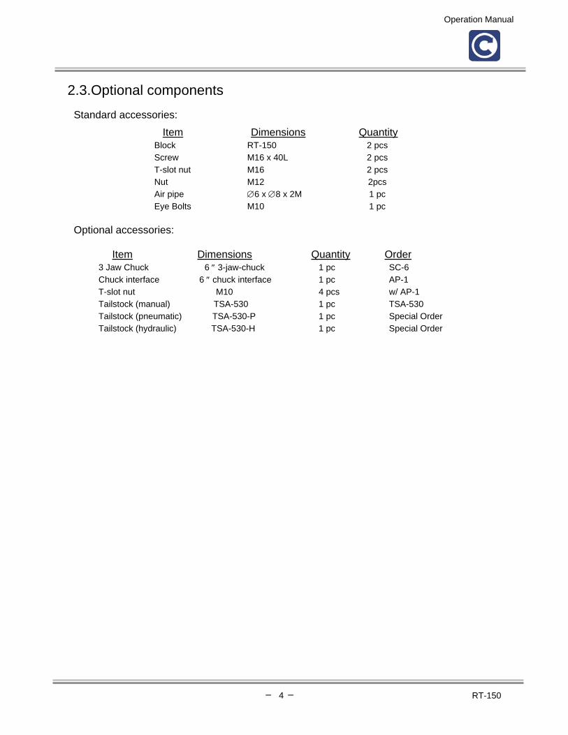
2.3.Optional components
Standard accessories: Item Dimensions Quantity
Block RT-150 2 pcs Screw M16 x 40L 2 pcs T-slot nut M16 2 pcs Nut M12 2pcs Air pipe ∅6 x ∅8 x 2M 1 pc Eye Bolts M10 1 pc
Optional accessories:
Item Dimensions Quantity Order
3 Jaw Chuck 6 ″ 3-jaw-chuck 1 pc SC-6 Chuck interface 6 ″ chuck interface 1 pc AP-1 T-slot nut M10 4 pcs w/ AP-1 Tailstock (manual) TSA-530 1 pc TSA-530 Tailstock (pneumatic) TSA-530-P 1 pc Special Order Tailstock (hydraulic) TSA-530-H 1 pc Special Order

Operation Manual
─ 5 ─ RT-150
3. INSTALLATION
3.1.Installation steps [ Installation method ] 1. Remove rust-preventing grease, then put rotary table on the machine table. 2. Connect MS connector and conduit and air line. 3. Align the table to the machine. 4. Clamp the rotary table on the machine table. 5. Make sure the 4th axis is turned on.
3.2.Notice Clamping force is driven by air, it is very important to install filter, regulator, and lubrication as close as possible to the pneumatic equipment for which they are used.
A. To protect all components from rust it is necessary to install filter, regulator & lubricator for pneumatic supply. B. The pneumatic pressure should be set between 57-85psi. When pressure is under 57psi, the mechanism’s
clamping accuracy will be reduced. C. Drain the water inside filter container everyday before operation.

Operation Manual
─ 6 ─ RT-150
3.3.How to avoid interference between Rotary table and M/C
A Width from center of guide-block on the CNC rotary table to the end of motor cover. B Height of motor cover. C M/C moving to end of the Y axis, the distance between locking center of CNC
rotary table to the safety door.
[Attention] Before you purchase or install the rotary table, check the width of 'A'. It should be smaller than the dimension of 'C'. Also consider the height of the table 'B', so it doesn’t interfere with the machine surround.
The most probable interference spot
Operation Manual
─ 7 ─ RT-150
4. MAINTENANCE & LUBRICATION
4.1. Lubrication replacement time and condition
1. Normal operation : Change lubricant every six months. 2. Continuous operation : Change lubricant every three months.
3. If machine is idle over six months, change lubricant oil before use.
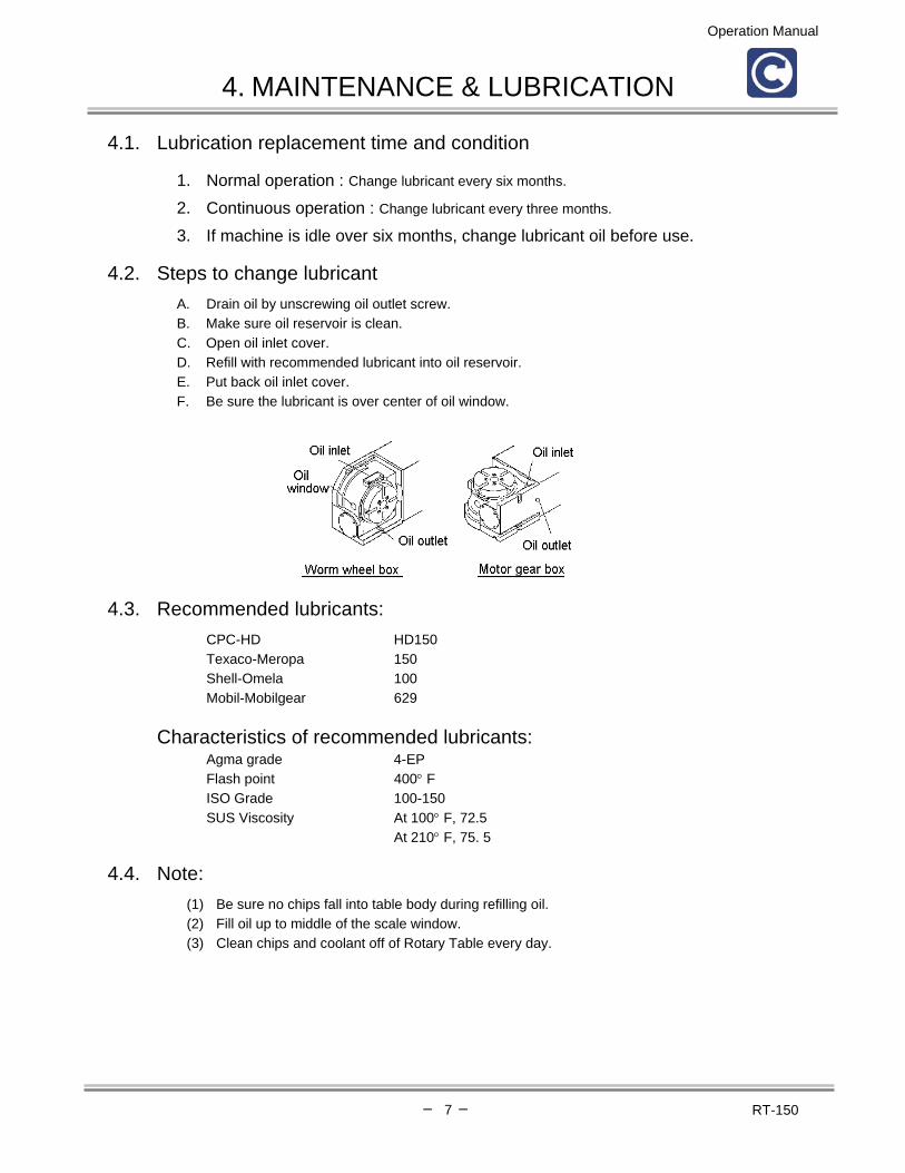
4.2. Steps to change lubricant A. Drain oil by unscrewing oil outlet screw. B. Make sure oil reservoir is clean. C. Open oil inlet cover. D. Refill with recommended lubricant into oil reservoir. E. Put back oil inlet cover. F. Be sure the lubricant is over center of oil window.
4.3. Recommended lubricants: CPC-HD HD150 Texaco-Meropa 150 Shell-Omela 100 Mobil-Mobilgear 629
Characteristics of recommended lubricants:
Agma grade 4-EP Flash point 400° F ISO Grade 100-150 SUS Viscosity At 100° F, 72.5 At 210° F, 75. 5
4.4. Note: (1) Be sure no chips fall into table body during refilling oil. (2) Fill oil up to middle of the scale window. (3) Clean chips and coolant off of Rotary Table every day.
Operation Manual
─ 8 ─ RT-150
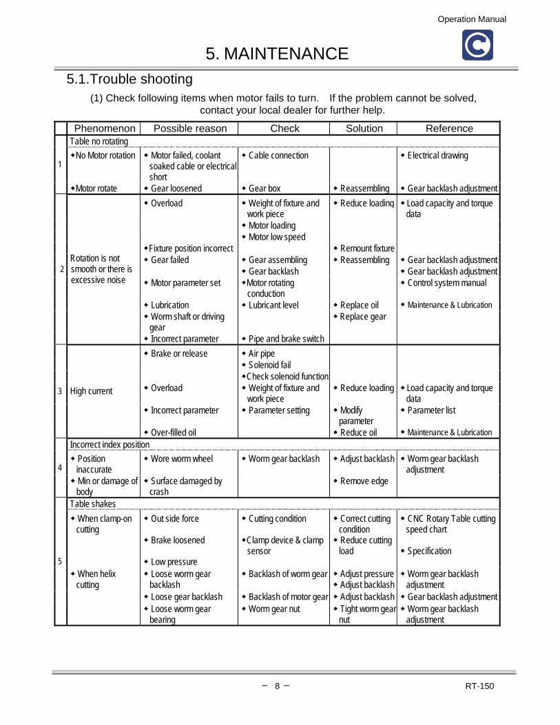
5. MAINTENANCE 5.1.Trouble shooting
(1) Check following items when motor fails to turn. If the problem cannot be solved, contact your local dealer for further help.
Phenomenon Possible reason Check Solution Reference Table no rotating
No Motor rotation Motor failed, coolant soaked cable or electrical short
Cable connection Electrical drawing 1
Motor rotate Gear loosened Gear box Reassembling Gear backlash adjustment Overload Weight of fixture and
work piece Reduce loading
Motor loading
Load capacity and torque data
Motor low speed Fixture position incorrect Remount fixture Gear failed Gear assembling Reassembling Gear backlash adjustment
Gear backlash Gear backlash adjustment Motor parameter set Motor rotating
conduction Control system manual
Lubrication Lubricant level Replace oil Maintenance & Lubrication Worm shaft or driving gear
Replace gear
2 Rotation is not smooth or there is excessive noise
Incorrect parameter Pipe and brake switch Brake or release Air pipe
Solenoid fail Check solenoid function
Overload Weight of fixture and work piece
Reduce loading Load capacity and torque data
Incorrect parameter Parameter setting Modify parameter
Parameter list
3 High current
Over-filled oil Reduce oil Maintenance & Lubrication Incorrect index position
Position inaccurate
Wore worm wheel Worm gear backlash Adjust backlash Worm gear backlash adjustment 4
Min or damage of body
Surface damaged by crash
Remove edge
Table shakes When clamp-on cutting
Out side force
Brake loosened
Low pressure
Cutting condition
Clamp device & clamp sensor
Correct cutting condition Reduce cutting load
CNC Rotary Table cutting speed chart
Specification
When helix cutting
Loose worm gear backlash
Backlash of worm gear Adjust pressure Adjust backlash
Worm gear backlash adjustment
Loose gear backlash Backlash of motor gear Adjust backlash Gear backlash adjustment
5
Loose worm gear bearing
Worm gear nut Tight worm gearnut
Worm gear backlash adjustment

Operation Manual
─ 9 ─ RT-150
Phenomenon Possible reason Check Solution ReferenceBrake function fail
Clamp fail Low pressure Air pressure regulator No brake signal O-ring worn out O-ring Replace O-ring
Seal worn out Piston seal Replace seal Pressure switch Pressure function
Pressure less than 71 psi Replace pressure switch Adjust pressure
Piston jammed O-ring and seal Replace O-ring or seal Brake cable Signal cable Reconnection
Signal delay Delay time too long Air line jammed
Parameter Air line
Reset parameter Clean air line
Piston jammed Piston and cylinder Clean piston and cylinder Rust cylinder Air filter and regulator Refill oil
6
Air leak Check air line Replace line or joint Zero return
Table no rotation Signal fail Signal cable Reconnection Non stop rotation Signal fail Signal cable Reconnection
Limit switch fail Limit switch Replace limit switch Dog fail Zero return dog Adjusting zero return dog
Position error Signal fail Signal cable Reconnection
7
Dog fail Zero return dog Adjusting zero return dog
(2) There are some things that can hamper machining. Please, take precautions to prevent the following possible problems to protect your machine and table.
Wrong method Precaution Rotary isn’t secured Please refer to installation chapter for securing rotary table on machine.
1. Check cutting tools for sharpness before use. 2. Avoid interference of tools and work piece. 3. Make sure the part is held securely to rotary table. 4. The height tolerance between table and tailstock is less than 0.03 5. Avoid cutting force greater than suggested value. 6. Return to zero point before working.
Cutting method
7. Backlash parameter should be set to the proper value, if needed.
Crashed Crashed machine may cause parts damage, inaccurate index or noise during indexing. We recommend that you send the table back to Centroid for repair if crashed

Operation Manual
─ 10 ─ RT-150
5.2.Checking the backlash 1. Turn off power and remove air supply. 2. The backlash can be measured with a dial indicator by inserting a flat steel bar into a T-slot of
the rotary table and applying force to the bar CW to CCW. 3. Measure the backlash again and make sure the backlash is between 0.0004 - 0.0008in.
Adjustment is required when a backlash of above 0.002in is observed. 4. The measurement is to be done on eight spots of the table by rotating it every 45°。
5.2.1.Worm gear and worm wheel backlash adjustment
A. Take off the motor cover (5-2), and loosen the 4 A screws then loosen screw B and tighten screw C to lift up motor.
B. Take off the worm shaft cover (5-3), loosen the 4 D screws, align the ∅8mm hole to T-slot to screw E position. C. Take out screw E’ and screw F’. Loosen screw F to free the eccentric shaft and tighten screw E to turn the
eccentric shaft closer to the worm wheel. Check the backlash again and make sure the backlash is between 0.0004in ~ 0.0008in by adjusting screw E and F.
D. Make sure the 4 screws D are tight and use screw E’ and screw F’ with tape seal to lock the adjusting screws. E. Loosen two C screws and tighten screw B (5-2) to adjust motor gear backlash, secure the motor by tightening
A screws. F. Connect the power then test the motor load and gear noise. Readjust the gear if the gear is noisy or motor
load is too high.
Dial gauge
Flat steel bar
(RT-150)

Operation Manual
─ 11 ─ RT-150
5.3.Origin mechanism A. A limit switch is used for origin or home as shown in Fig. ( 5 - 4 ) B. Origin dog attached internally to the rotary table, actuates the limit switch to have it
output a signal 1°~2° before home position.
C. To adjust the dog position, bring the dog, under jog mode to the position of the oil inlet (Cover No.31), where the adjustment can be done easily.
D. Loosen the cap-screws of dog. Move the dog to a proper position. The dog has slots for
about ± 0.3in of movement.
E. CAUTION : When you loosen the cap-screws, don't loosen them completely – this will
prevent them from dropping into the interior of the machine.

Operation Manual
─ 12 ─ RT-150
5.4.System drawing
RT-
150

Operation Manual
─ 13 ─ RT-150
5.5.Part list RT-150
Part No. Description Q'ty Material Drawing No. Remark 1 Top cover 1 FC30 CNC150-001 2 Top cover 1 SS41 CNC150-002 3 Spindle 1 SCM4 CNC150-003 4 Worm wheel 1 ALBC2 CNC150-004 6 Compression ring 1 S45C CNC150-043 7 Base 1 FC30 CNC200R-007 8 Brake piece 1 SUS304 CNC150-008 9 Brake plate 6 S45C CNC150-010 10 Piston 1 S45C CNC150-011 11 Base cover 1 FC30 CNC150-012 12 Worm shaft back cover 1 S45C CNC150-013 13 Packing 1 S45C CNC150-014 14 Nut 1 S45C CNC150-015 15 Worm shaft 1 SNCM21 CNC150-016 16 Eccentric tube 1 FCD55 CNC150-017 17 Worm shaft back cover 1 S45C CNC150-018 18 Gear 1 SCM21 CNC150-019 19 Gear 1 SCM21 CNC150-020 Centroid DC 19 Gear 1 SCM21 CNC150-020-1 Centroid AC 19 Gear 1 SCM21 CNC150-020-2 19 Gear 1 SCM21 CNC150-020-3 19 Gear 1 SCM21 CNC150-020-4 20 Taper sleeve 1 S45C CNC150-021 21 Adjustable plate 1 FCD55 CNC150-022 Centroid 22 Packing 4 S45C CNC150-023 23 Adjustable bracket 1 SS41 CNC150-024 Centroid 24 Zero point 1 S45C CNC150-025 28 Indicator 1 SS41 CNC150-029-1 29 Screw 1 S45C CNC150-030 30 key 1 S45C CNC251-048 31 cover 1 S45C CNC150-032 32 key 1 SK2 CNC150-033 33 Motor cover 1 SS41 CNC150-034-4 Centroid 34 Cover 1 SS41 CNC150-035-2 Centroid DC 34 Cover 1 SS41 CNC150-035-3 Centroid AC 35 Protecting cover for
adapter 1 SS41 CNC150-037 Centroid
36 Fixed plate for adapter 1 SS41 CNC150-038-4 Centroid DC 36 Fixed plate for adapter 1 SS41 CNC150-038-5 Centroid AC 37 Block 2 S45C CNC150-041-1 38 Fixed plate 1 S45C CNCT201-022

Operation Manual
─ 14 ─ RT-150
RT-150
Part No. Description Specification Q'ty Brand Remark A1 Needle bearing NK17/20 2 IKO A2 Needle bearing RNA4911 1 IKO A3 Thrust bearing AZ17309 2 IKO A4 Thrust bearing AXK75100 2 IKO A5 Thrust bearing plate AS75100 4 IKO A6 O-ring G30 1 NOK A7 O-ring G50 1 NOK A8 O-ring G60 1 NOK A9 O-ring G70 1 NOK Centroid A10 O-ring G80 1 NOK A11 O-ring G145 1 NOK A12 O-ring G155 1 NOK A13 O-ring P8 1 NOK A14 O-ring P18 1 NOK A15 O-ring P41 1 NOK A16 O-ring P80 1 NOK A17 Oil seal TC1/2"x1"x1/4" 1 NOK CMC ME3528 A18 Oil seal TC17x30x8 1 NOK A19 Oil seal TC80x105x13 1 NOK A20 O-ring G100 1 NOK A21 Oil seal UHS60A 1 NOK A22 Screw M4x12L (CAP) 4 YM A23 Screw M4x14L (CAP) 3 YM A24 Screw M5x12L (CAP) 3 YM A25 Screw M5x20L (CAP) 4 YM A26 Screw M5x25L (CAP) 3 YM Centroid A27 Screw M6x12L (CAP) 2 YM A28 Screw M6x20L (CAP) 8 YM Centroid A29 Screw M6x25L (CAP) 2 YM Centroid A30 Screw M6x30L (CAP) 4 YM Centroid A31 Screw M6x60L (CAP) 6 YM A32 Screw M8x35L (CAP) 4 YM A33 Screw M8x40L (CAP) 4 YM Centroid A34 Screw M4x8L (BH) 25 YM Centroid A35 Screw M5x10L (BH) 12 YM A36 Screw M5x14L (BH) 4 YM A37 Screw M6x6L (SET) 2 YM A38 Screw M6x8L (SET) 1 YM A39 Screw M6x20L (SET) 2 YM

Operation Manual
─ 15 ─ RT-150
RT-150
Part No. Description Specification Q'ty Brand Remark A40 Nut M16 2 YM A41 Screw M16x75L 2 YM A42 T-key M16 2 YM A43 Eye bolts M10 1 TG A44 Stopper PT1/4 3 A45 Pin NO.4x32L 4 Yoeng Feng A46 C ring φ 25 1 Yoeng Feng
A47 Oil window PF1/2 1 Nok A48 Motor 1 Centroid A48 Motor 35 in/lb AC 1 Centroid A49 Pressure
switch PSA-SD 1 Nisshingauge
A50 Limit switch SHL-Q2155 1 Omron A51 Solenoid TZ511T-S9-WA 1 Nok Tec A52 PU-belt φ 2x300L 1

Operation Manual
─ 16 ─ RT-150
6. RECYCLING AND DISPOSAL
A. Drain all lubricant oil from CNC Rotary Table. B. Disassemble the plastic and rubber form CNC Rotary Table (refer the system drawing) C. Sort all parts according to material.
[ Note ] : Please refer to local recycle laws for recycling and disposal.

Operation Manual
─ 17 ─ RT-150
7. APPENDIX
7.1. Load capacity and torque data
RT-150
Item Example Allowable value
Vertical W = 165 lbs / 75 kg
Max. Load
Horizontal
fgtyy
W = 330 lbs / 150 kg
F = 1,763 lbs / 800 kg
F x L = 11.2 kg m
22.5 lbs x 3ft Max. Radial Load
F x L = 40 kg m
80.6 lbs x 3ft
Max. Working Inertia
4.08 kg cm sec2
22.8 lbs x in x sec2
Spindle Drive Torgue
9 kg m
18.1 lbs x 3 ft
J= WD (8x980)
2

Operation Manual
─ 18 ─ RT-150
7.2. CNC Rotary Table cutting speed chart The direct instruction system under F code is employed for giving instructions of CNC Rotary Table feeding speed (movements of degree per minute).such as [ example : F100 = 100 °/min. = 0.28 R.P.M. ] Relation between a feed of tool and a circular arc dia. D at a time of cutting is listed in the following chart. How to use chart : When an outer periphery of work D = ∅ 160 mm is to be cut by end milling at a speed of 110 mm / min. F value obtained as f = 80 from 111 mm / min. corresponding to D = ∅ 160 mm at the topmost line.
F
R.P.M.
30
40
50
60
80
100
120
140
160
180
200
230
250
300
400 ∅D500
F
F 10 0.03 3 4 5 6 8 9 11 13 15 17 19 22 24 28 38 47 F 10F 20 0.06 6 8 9 11 15 19 23 26 30 34 38 43 47 57 75 94 F 20F 30 0.08 8 10 13 15 20 25 30 35 40 45 50 58 63 75 100 125 F 30F 40 0.11 10 14 17 21 28 35 42 48 55 62 69 80 87 104 138 173 F 40F 50 0.14 13 18 22 26 35 44 53 62 70 79 88 101 110 132 176 220 F 50F 60 0.16 15 20 25 30 40 50 60 70 80 91 101 116 126 151 201 252 F 60F 70 0.19 18 24 30 36 48 60 72 84 96 107 119 137 149 179 239 299 F 70F 80 0.22 21 28 35 41 55 69 83 97 111 124 138 159 173 207 276 346 F 80F 90 0.25 24 31 39 47 63 79 94 110 126 141 157 181 196 236 314 393 F90F100 0.28 26 35 44 53 70 88 106 123 141 158 176 202 220 264 352 440 F100F110 0.31 29 39 49 58 78 97 117 136 156 175 195 224 244 292 390 487 F110F120 0.33 31 41 52 62 83 104 124 145 166 187 207 239 259 311 415 519 F120F130 0.36 34 45 57 68 90 113 136 158 181 204 226 260 283 339 452 566 F130F140 0.39 37 49 61 74 98 123 147 172 196 221 245 282 306 368 490 613 F140F150 0.42 40 53 66 79 106 132 158 185 211 237 264 303 330 396 528 660 F150F160 0.44 41 55 69 83 111 138 166 193 221 249 276 318 346 415 553 691 F160F170 0.47 44 59 74 89 118 148 177 207 236 266 295 340 369 443 591 739 F170F180 0.50 47 63 79 94 126 157 189 220 251 283 314 361 393 471 628 786 F180F190 0.53 50 67 83 100 133 167 200 233 266 300 333 383 416 500 666 833 F190F200 0.55 52 69 86 104 138 173 207 242 276 311 346 397 432 518 691 864 F200F210 0.58 55 73 91 109 146 182 219 255 292 328 364 419 456 547 729 911 F210F220 0.61 57 77 96 115 153 192 230 268 307 345 383 441 479 575 766 958 F220F230 0.64 60 80 101 121 161 201 241 282 322 362 402 463 503 603 804 1006 F230F240 0.67 63 84 105 126 168 211 253 295 337 379 421 484 526 632 842 1053 F240F250 0.69 65 87 108 130 173 217 260 304 347 390 434 499 542 650 867 1084 F250F260 0.72 68 90 113 136 181 226 271 317 362 407 452 520 566 679 905 1131 F260F270 0.75 71 94 118 141 188 236 283 330 377 424 471 542 589 707 942 1178 F270F280 0.77 73 97 121 145 194 242 290 339 387 435 484 556 605 726 968 1210 F280F290 0.81 76 102 127 153 204 255 305 356 407 458 509 585 636 764 1018 1273 F290F300 0.83 78 104 130 156 209 261 313 365 417 469 522 600 652 782 1043 1304 F300F310 0.86 81 108 135 162 216 270 324 378 432 486 540 624 676 811 1081 1351 F310F320 0.90 85 113 141 170 226 283 339 396 452 509 565 650 707 848 1131 1414 F320F330 0.92 87 116 145 173 231 289 347 405 462 520 578 665 723 867 1156 1445 F330F340 0.94 89 118 148 177 236 295 354 413 472 531 591 679 738 886 1181 1476 F340F350 0.97 91 122 152 183 244 305 366 427 488 548 609 701 762 914 1219 1524 F350F360 1.00 94 126 157 189 251 314 377 440 503 566 628 723 786 943 1257 1571 F360F370 1.03 97 129 162 194 259 324 388 458 518 582 647 744 809 971 1294 1618 F370F380 1.06 100 133 167 200 266 333 400 466 533 599 666 766 833 999 1332 1665 F380F390 1.08 102 136 170 204 271 339 407 475 543 611 679 780 848 1018 1357 1697 F390F400 1.11 105 139 174 209 279 349 418 488 558 628 697 802 872 1046 1395 1744 F400F410 1.14 107 143 179 215 286 358 430 501 573 645 716 824 895 1074 1432 1791 F410F420 1.17 110 147 184 221 294 368 441 515 588 662 735 845 919 1103 1470 1838 F420F430 1.19 112 150 187 224 299 374 449 523 598 673 743 860 935 1121 1495 1869 F430F440 1.22 115 153 192 230 307 383 460 537 613 690 767 882 958 1150 1533 1917 F440F450 1.25 118 157 196 236 314 398 471 550 628 707 785 908 982 1178 1571 1964 F450F460 1.28 121 161 201 241 322 402 483 563 643 724 804 925 1005 1206 1608 2011 F460F470 1.31 123 165 206 247 329 412 494 576 658 741 823 946 1029 1235 1646 2058 F470F480 1.33 125 167 209 251 334 418 501 585 668 752 836 961 1045 1253 1671 2089 F480F490 1.36 128 171 214 256 342 427 513 598 684 769 855 983 1068 1282 1709 2187 F490F500 1.39 131 175 218 262 349 437 524 611 699 786 873 1004 1092 1310 1747 2184 F500
30 40 50 60 80 100 120 140 160 180 200 230 250 300 400 500
Operation Manual
─ 19 ─ RT-150
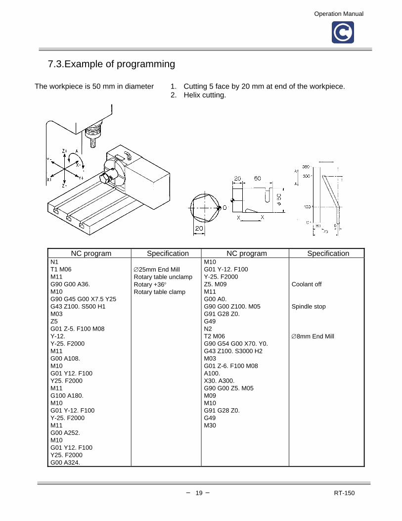
7.3.Example of programming The workpiece is 50 mm in diameter 1. Cutting 5 face by 20 mm at end of the workpiece. 2. Helix cutting.
NC program Specification NC program Specification N1 T1 M06 M11 G90 G00 A36. M10 G90 G45 G00 X7.5 Y25 G43 Z100. S500 H1 M03 Z5 G01 Z-5. F100 M08 Y-12. Y-25. F2000 M11 G00 A108. M10 G01 Y12. F100 Y25. F2000 M11 G100 A180. M10 G01 Y-12. F100 Y-25. F2000 M11 G00 A252. M10 G01 Y12. F100 Y25. F2000 G00 A324.
∅25mm End Mill Rotary table unclamp Rotary +36° Rotary table clamp
M10 G01 Y-12. F100 Y-25. F2000 Z5. M09 M11 G00 A0. G90 G00 Z100. M05 G91 G28 Z0. G49 N2 T2 M06 G90 G54 G00 X70. Y0. G43 Z100. S3000 H2 M03 G01 Z-6. F100 M08 A100. X30. A300. G90 G00 Z5. M05 M09 M10 G91 G28 Z0. G49 M30
Coolant off Spindle stop ∅8mm End Mill

Operation Manual
─ 20 ─ RT-150
7.4.Machine computer and rotary table control connection 7.4.1.Machine with 3 axes
7.4.2.Machine with 4 axes
Centroid Controller
Air Line
Air Line

Operation Manual
─ 21 ─ RT-150
7.5.How to use tailstock 7.5.1.Manual tailstock
1. To lock piston: Turn locking handle CCW to release piston or CW to lock the piston (7-1). 2. To move forward and backward: Turn handwheel CW to move piston forward and
CCW for backward. 3. To remove the center: Move the piston backward CCW to the end, this will release the center.
7.5.2.Power tailstock (pneumatic or hydraulic)
1. To lock piston: Turn locking handle CCW to release piston or CW to lock the piston (7-2). 2. To move forward and backward: Operating the pneumatic (hydraulic) solenoid will move
the piston forward or backward (7-3). 3. To replace the center: Move the piston forward until the oval hole is complete out of body
then stick in the taper tool to remove the center.
7.5.3.Maintenance: It is recommended to add grease to the lubricant holes every six months for maintenance.
Taper tool

Operation Manual
─ 22 ─ RT-150
7.6.Parameter Setting for Rotary Tables See also the following TECH NEWS Documents:
1.TB012 Removing and installing Servo Drives. 2.TB013 3 axis to 4 axis upgrade with an RTK1 PLC. 3.TB022 Modifying CNC7.hom file for homing program.
Steps
*Set the Machine Configuration as below for the 4th axis only. *DO NOT CHANGE THE VALUES FOR 1, 2, 3 AXIS!
1. Place jumpers on the RTK2-B H1 between pins 1 and 2, and pins 3 and 4. See Diagram
Go to the proper screens as follows: F1<Setup>, F3<Config>, Password= 137 <Enter>; then F3<Params> or F2<Machine> as instructed below. Always be sure to use F10 <Save> before exiting.
2. In the F2<Machine> configuration, set the #4 Axis label to W and edit this same line as
indicated below to replicate the proper configuration for the proper rotary table.

Operation Manual
─ 23 ─ RT-150
Rotary Table Parameters:
Rotary Table Mtr/T
bl
Ratio
Slow
Jog
Fast
Jog
Max
Rate
Rev/
degree
Encod
e
counts
Limit
+ -
Home
+ -
Dir
Troyke 180:1 360 720 1,200 0.5 8,000 0 0 * * N
Yuasa SUDX
220 w/5.27
90:1 2,000 3,937 3,937 0.25 8,000 0 0 * * N
Yuasa SUDX
220 w/6.00
90:1 2,000 12,000 12,000 0.25 8,000 0 0 * * N
Yuasa SUDX
140 w/5.27
70:1 2,000 3,937 3,937 0.2 8,000 0 0 * * N
Yuasa SUDX
140 w/6.00
70:1 2,000 12,000 12,000 0.2 8,000 0 0 * * N
DC 90:1 2,000 9,000 9,000 .25 8,000 0 0 * * N Centroid
RT-200 AC 90:1 5,000 11,500 11,500 .25 8192 0 0 * * N
DC 90:1 2,000 9,000 9,000 .25 8,000 0 0 * * N Centroid
RT-150 AC 90:1 5,000 11,500 11,500 .25 8192 0 0 * * N * Determined by PLC
TABLE 1
3. To figure your Revs/degree you need to divide the Motor Revs./ Table Revs. ratio by 360. See table 1.
4. In the F3<Params> screen, change parameter 94 to 1.0 (this will flag that axis as rotary). The conversational software will then display degrees, minutes, and seconds for that axis in linear moves. Also change parameter 98 to 45.0 (the autotune move distance).
*To find feedrate for a rotary axis in degrees/min, you must do the following: (Surface Velocity/Part Diameter) * (114.591559) = Deg/Min
The degree per minute is the input required for the feedrate.
5. From the main screen of CNC7, press F6<Edit> and open the file c:\cnc7\cnc7.hom. Add these lines at the end of the file for homing the rotary axis. If you have a home/limit switch add these lines - M92/W M26/W If you don't have a home/limit switch just add this line - M26/W 6. Some earlier Centroid Controls may require an updated RTK2 assembly if you find that H1
is not installed on the circuit board and/or a PLC Program modification in order to use the "Clamp" feature. Call Tech Support if this applies.

Operation Manual
─ 24 ─ RT-150
Special Note For Rotary Table with DC brush motor: The Kd parameter will need to be adjusted for the 17 lb/in motor that is installed in the table.
Follow the instructions below. Go to the proper screens as follows: F1<Setup>, F3<Config>, Password= 137 <Enter>; then
F4<PID>, F1<PID> Use the right arrow key to move over to the Kd column then the down arrow key to get to the correct row and axis, in this case W. Change the value in this field to 5.000. Always be sure to use F10 <Save> before exiting.
Testing • Check the clamp. With proper air supply, press <F3> for MDI then M10<enter>(clamp
on). Verify that the table is clamped, or locked, into position so that it cannot rotate. Issue an M11<enter>(clamp off) to unclamp the table.
• Jog the 4th axis in both directions to verify proper motor wiring. (Note: If the motor power leads are reversed, an axis will move the same direction a small amount no matter which jog key is pressed. If this is the case call Tech Support)
• Verify proper homing. During homing sequence, the table will turn at the slow jog rate to the switch and then come off the switch at 24 deg/min a short amount before setting home. (Note: If the input is not connected, the table will turn at 24deg/min indefinitely.)
• Go into MDI. If the rotary table is labeled W, enter the following commands: W0<cycle start> W360 <cycle start>. Verify that the table completes one revolution.
• If the table is the 4th axis, set parameter 98 to 45. This will cause autotune to move 45 degrees on the rotary table. See chapter 10 in the manual. Run Autotune.
Field upgrade checklist: - a new PLC program for 4 axis system - a new wiring diagram - a 4th axis drive similar to the one in the machine (i.e.. is the 3 axis 12,12,15 brake? or a 12,12,12? etc.) - a new limit switch cable that goes from the PLC to the drive. - a wiring harness for the inside of the magnetics cabinet and tools to install the connector in the bottom of the magnetics cabinet. (If applicable)

Operation Manual
─ 25 ─ RT-150
7.7. Using 4th Axis on Offline Mill Intercon In order to enable 4th axis support using Off-line Intercon, the control parameter and configuration files must be set correctly. Follow the steps below to enable 4th axis in off-line programming. Setting correct parameters on the control (1) At the control, be sure that parameter 94 = 1.0, which is a signal to Intercon that the 4th axis is rotary. To access the parameters screen starting form the main screen, use <F1> Setup, <F3> Config, enter the password of 137, and then <F3> Params. Remember to press <F10> to save changes. (2) The 4th axis should be labeled in the Machine Configuration with a letter other than N, typically B or W. To access the Machine Configuration screen starting form the main screen, use <F1> Setup, <F3> Config, enter the password of 137, and then <F2> Machine, followed by <F2> Motor. Remember to press <F10> to save changes. (3) Another good idea is to set the Console type in the Control Configuration to be Offline, so that the function keys will also be labeled, as the off-line keyboard function keys obviously will not line up with the off-line computer monitor. To access the Control Configuration screen starting form the main screen, use <F1> Setup, <F3> Config, enter the password of 137, and then <F1> Control. Remember to press <F10> to save changes. The console type should be changed back to the original setting after the files have been copied to a floppy disk. Copying the information from the control to a floppy disk (4) Insert a blank, formatted floppy disk into the floppy drive. (5) From the main screen, exit to DOS by pressing <CTRL + ALT + X>, i.e., all three keys at the same time. (6) Execute the following commands: copy cnc7.prm a:\ <ENTER> copy cnc7.cfg a:\ <ENTER>
Copying the information from the floppy disk to the off-line system There are several ways to accomplish this task, especially when the off-line computer operating system is Windows. What needs to be done is that the two files on the floppy disk (cnc7.prm and cnc7.cfg) must be copied into the \CNC7 directory of the off-line computer system, replacing the ones that are there. Assuming the off-line system is DOS based, here would be the commands to type at the command line. Using a Windows 9x operating system, the same commands could be typed into the Run dialog box accessible via the Start Menu. copy a:\*.* c:\cnc7 <ENTER> Try using the offline Intercon and verfiy that 4th axis is enabled.

Operation Manual
─ 26 ─ RT-150
7.8.Converting inches(mm)/minute to degrees/minute Overview This document gives the formulas for calculating the feed for a rotary axis. The feed rate for rotary axis on a Centroid Control is in degrees per minute. Formulas for Converting inches (millimeters) per minute to degrees per minute. Degrees per minute = Inches per minute / Diameter * 114.5916 Degrees per minute = Millimeters per minute / Diameter * 114.5916 Example #1: 20 inches per minute, Cutting 3 inch diameter Degrees per minute = 20/3*114.5916 Degrees per minute = 6.6667*114.5916 Degrees per minute = 763.9478 Example #2: 508 millimeters per minute, Cutting 76.2 millimeter diameter Degrees per minute = 508/76.2*114.5916 Degrees per minute = 6.6667*114.5916 Degrees per minute = 763.9478 Formulas for Converting Degrees per minute to inches (millimeters) per minute. Inches per minute = Degrees per minute * Diameter / 114.5916 Millimeters per minute = Degrees per minute * Diameter / 114.5916 Example #3: 4000 Degrees per minute, Cutting 2 Inch Diameter Inches per minute = 2000 * 2 / 114.5916 Inches per minute = 4000 / 114.5916 Inches per minute = 34.907 Example #4: 4000 Degrees per minute, Cutting 50 millimeter diameter Millimeter per minute = 4000 * 50 / 114.5916 Millimeter per minute = 200000 / 114.5916 Millimeter per minute = 1745.329

Operation Manual
─ 27 ─ RT-150
7.9.110 Volt Rotary Table MS Connectors Problem Description: This Tech Bulletin is about the 4th Axis Rotary table connectors on Centroid Controls configured for 110 Volt rotary tables. Before the week ending April 26th 2002 Centroid shipped every Control setup for 4th axis in the same way, regardless of whether it was setup for 24V or 110V operation. This has been known to cause problems if someone would try and connect the Rotary table setup for 24V operation to a Control set for 110V.
Solution: To combat this problem Centroid will begin shipping Controls setup for 110V Rotary operation with the MS connector in a different configuration. The new configuration for the MS connector is what is called the ‘Z’ position. The cables shipped for 110V operation will also be set to the ‘Z’ position. You can clearly see the difference between the ‘Z’ position and the normal position in the diagrams below. All diagrams show the connectors when looking from the front.
Female MS Connector Set For 24V: Female MS Connector in ‘Z’ For 110V:
Male MS ConnectorSet For 24V: Male MS Connector in ‘Z’ For 110V:

Operation Manual
─ 28 ─ RT-150
It is recommended that all Controls in the field have the connectors changed to the ‘Z’ position if they are set for 110V operation. This ensures that there will be no confusion in the future with these machines and the cables. Note. It is still just as important to have the correct cable for the rotary table in use.
Instructions for changing connector configuration: To set up the connectors to the ‘Z’ position you need to follow the simple steps below:
Female:
1. Remove socket from cabinet 2. Remove snap ring on back of socket holding connector together 3. Slide out center of connector 4. Rotate to ‘Z’ position. Note: You may have to remove some material from the center section in order for it to slide into the ‘Z’ position. To do this simply use a Dremel or an exacto-knife to remove the material as needed 5. Slide center back into connector body 6. Replace snap ring 7. Replace socket back in cabinet
Male:
1. Unscrew back of connector 2. Remove snap ring in back of connector 3. Slide out center section of connector 4. Rotate center c\section to the ‘Z’ position. Note: You may have to remove some material from the center section in order for it to slide into the ‘Z’ position. To do this simply use a Dremel or an exacto-knife to remove the material as needed 5. Slide center section back into socket 6. Replace snap ring 7. Screw back of connector back into place

Operation Manual
─ 29 ─ RT-150
7.10.Plumbing Diagram for Air Line on Centroid Rotary Tables

Operation Manual
─ 30 ─ RT-150
7.11.DC Wiring

Operation Manual
─ 31 ─ RT-150
7.12.AC Wiring

Operation Manual
─ 32 ─ RT-150
7.13.DC Rotary Table Connections

Operation Manual
─ 33 ─ RT-150
7.14.AC Rotary Table Connections