Centro de Transferencia de Tecnología en Transportación...
176
Centro de Transferencia de Tecnología en Transportación Departamento de Ingeniería Civil y Agrimensura UPR-Recinto Universitario de Mayagüez Call Box 9000 * Mayagüez, PR 00681 Tel. 787-834-6385 * Fax: 787-265-5695 * www.uprm.edu/prt2 22 y 24 de septiembre de 2015 Instructora Dra. Beatriz I. Camacho Padrón Departamento de Ingeniería Civil y Agrimensura UPR – Recinto Universitario de Mayagüez 29 Años de Excelencia en el Adiestramiento de Oficiales de Transportación a Nivel Municipal, Estatal, y Federal en Puerto Rico e Islas Vírgenes
Transcript of Centro de Transferencia de Tecnología en Transportación...

Centro de Transferencia de Tecnología en TransportaciónDepartamento de Ingeniería Civil y Agrimensura
UPR-Recinto Universitario de MayagüezCall Box 9000 * Mayagüez, PR 00681
Tel. 787-834-6385 * Fax: 787-265-5695 * www.uprm.edu/prt2
22 y 24 de septiembre de 2015
Instructora
Dra. Beatriz I. Camacho PadrónDepartamento de Ingeniería Civil y Agrimensura
UPR – Recinto Universitario de Mayagüez
29 Años de Excelencia en el Adiestramiento de Oficiales de Transportación
a Nivel Municipal, Estatal, y Federal en Puerto Rico e Islas Vírgenes

9/24/2015
1
Dr. Beatriz Camacho
Professor
Department of Civil Engineering
and Surveying
University of Puerto Rico at
Mayaguez
1
Definition
Historical Development
Applications
Advantages & Disadvantages
Relative Costs
Systems Differentiation
Site Evaluation
Project Evaluation
Design
Contracting Methods
2

9/24/2015
2
Generic term that includes reinforced soil
When multiple layers of inclusions act as
reinforcement in soils placed as fill.
Multiple horizontal layers of man-made
elements that act as reinforcements for
the soil used as infill materials.
Constructed with artificial reinforcing.
Usually steel or geosynthetics.
3
Retaining structures
Reinforced concrete
Designed as gravity or cantilever walls
Essentially rigid structures and cannot
accommodate significant differential
settlements unless founded on deep
foundations.
4

9/24/2015
3
Many primitive people used sticks and
branches to reinforce mud dwellings.
French settlers along the Bay of Fundy in
Canada used sticks to reinforce mud dikes.
Some other early examples include dikes of
earth and tree branches, which have been
used in China and along the Mississippi River
in the 1880s.
Other examples include wooden pegs used
for erosion and landslide control in England,
and bamboo or wire mesh, used universally
for revetment erosion control.
5
The modern methods of soil
reinforcement
Pioneered by the French architect and
engineer Henri Vidal in the early 1960s.
His research led to the invention and
development of Reinforced Earth®, a
system in which steel strip reinforcement
is used.
First wall to use this technology in the
United States was built in 1972 on
California State Highway 39, northeast of
Los Angeles.
6

9/24/2015
4
Geogrids for soil reinforcement were
developed around 1980.
The first use of geogrid in earth
reinforcement was in 1981.
7
Typical Section of a Reinforced Earth
Structure 8
9/24/2015
5
9
ORIGINAL
GROUND
RANDOM BACKFILL
SELECT BACKFILL
SOIL REINFORCEMENT
FILTER FABRICWALL/REINFORCEMENT
CONNECTION
COPING
WALL
FACING
PANELS
WOODEN
WEDGES
SPACERS
LEVELING
PAD
Retained backfill
Fill material located between the
mechanically stabilized soil mass and the
natural soil.
Reinforced backfill
Fill material in which the reinforcements
are placed.
10

9/24/2015
6
Facing
To prevent the soil from raveling out
between the rows of reinforcement.
11Precast concrete panels
precast concrete panels,
12http://precast.org/tag/mse-walls/

9/24/2015
7
dry cast modular blocks,
13http://armaterra.com/?page_id=24
gabions,
14

9/24/2015
8
sheets of geosynthetics,
15http://www.flexmse.com/vegetated-retaining-wall/
wire mesh, shortcrete, wood lagging and panels.
16

9/24/2015
9
Modular Block wall
(MBW)
Most common
retaining wall
constructed today.
17
Modular Block Retaining
Wall
Modular Block wall (MBW)
One of the advantages of MBW is that they
are individual blocks so if a block shifts a
little, the wall won't break.
They are porous so water will pass through
the wall which makes them less susceptible
to hydrostatic pressure.
18

9/24/2015
10
20
Geosynthetics
Polymeric materials
21
Geostrip

9/24/2015
11
Geosynthetics
geotextiles, geomembranes, geonets, and grids.
22
GeogridGeotextile
Coping The coping is used to tie in the top of the wall panels
and to provide a pleasing finish to the wall top. It can be cast-in-place or prefabricated segments.
Extensible Reinforcement Polymeric reinforcement materials (exhibits creep
characteristics under stress).
Filter Fabric A geotextile filter fabric is used to cover the joint
between panels. It is placed on the backside of the panels. This keeps the soil from being eroded through the joints and allows any excess water to flow out.
Inextensible Reinforcement Metallic reinforcement material (both strips and grids)
(does not exhibit creep characteristics under stress).
23

9/24/2015
12
Leveling Pad The leveling pad is a non-reinforced concrete pad
used to provide a level, consistent surface at the proper grade to place the panels.
Original Ground This is the existing ground surface at the site.
Soil Reinforcement Soil reinforcement holds the wall facing panels in
position and provides reinforcement for the soil.
Can be strips, grids, or mesh.
Can be made of steel (inextensible materials) or polymers (extensible materials).
24
Spacers
Wall panel spacers are typically ribbed elastomeric or
polymeric pads.
inserted between panels to help provide the proper spacing.
Proper spacing keeps the panels from having point contact and spalling
the concrete.
Wall/Reinforcement Connection
This is where the connection is made between the wall facing
panel and the soil reinforcement
Wooden Wedges
Used to help hold the panels at the correct batter during the
filling operation.
Should be made from hard wood (such as oak, maple or ash).
25

9/24/2015
13
Used for:
retaining walls,
access ramps,
bridge abutments,
waterfront structures (seawalls),
dams,
dikes,
among others.
26
27

9/24/2015
14
28
Retaining Wall
29

9/24/2015
15
I-25 South Broadway Access Ramp-Denver, Colorado-photo simulation
32
Access Ramp
http://www.poitra.com/DesignVisualization_I-25BroadwayAccessRamp.html
33

9/24/2015
16
34
Bridge Abutment
35

9/24/2015
17
36
Waterfront structure-Seawall
37
California

9/24/2015
18
38
39

9/24/2015
19
Simple construction procedure
Reduced construction time.
No need of special skills for construction
Requires less site preparation than other
alternatives.
For construction need less space in front
of the structure
40
Reduce right-of-way acquisition.
Tolerant to deformations
No need of rigid unyielding foundation
support
Higher resistance to seismic loading
Cost effective construction technique.
Can be built to heights larger than 100ft
(30m)
41

9/24/2015
20
Requires a large space behind the wall for
internal and external stability.
cost of importing suitable fill material
may increase construction cost
At sites where there is a lack of granular soils
Suitable design criteria are required to
address corrosion of steel reinforcing
elements,
deterioration of certain types of exposed
facing elements and
potential degradation of polymer
reinforcement in the ground.
42
Specifications and contracting practices
have not been fully standardized.
The design of soil-reinforced systems
often requires a shared design
responsibility between material suppliers
and owners.
43

9/24/2015
21
Site specific costs of a soil-reinforced
structure are a function of:
cut-fill requirements,
wall/slope size and type,
in-situ soil type,
available backfill materials,
facing finish,
temporary or permanent application.
44
MSE walls result in savings on the order of
25 to 50 percent in comparison with a
conventional reinforced concrete
retaining structure
Substantial savings is obtained by
elimination of the deep foundations.
Savings are evident in walls larger than 10 ft
(3m)
45

9/24/2015
22
For segmental precast concrete faced structures, typical relative costs are: Erection of panels and contractors profit
- 20 to 30 percent of total cost.
Reinforcing materials - 20 to 30 percent of total cost.
Facing system - 25 to 30 percent of total cost.
Backfill materials including placement -35 to 40 percent of total cost
46
A system is defined as a complete
supplied package that includes:
design, specifications and all
prefabricated materials.
Often technical assistance during the
planning and construction phase is also
included.
47

9/24/2015
23
MSE systems can be described by:
reinforcement geometry,
stress transfer mechanism,
reinforcement material,
extensibility of the reinforcement material, and
type of facing and connections.
48
Reinforcement Geometry
Linear unidirectional – e.g Strips, including smooth or ribbed steel
strips, or
coated geosynthetic strips over a load-carrying fiber.
Composite unidirectional – Grids or bar mats
Planar bidirectional – Continuous sheets of geosynthetics,
welded wire mesh, and
woven wire mesh.
49

9/24/2015
24
Reinforcement Material:
Metallic reinforcements - Typically of mild
steel.
Usually galvanized or may be epoxy coated.
Nonmetallic reinforcements - Generally
polymeric materials
polypropylene, polyethylene, or polyester.
50
Reinforcement Extensibility
Inextensible –
Deformation of the reinforcement at failure is
much less than the deformability of the soil.
Steel strip and bar mats
Extensible –
Deformation of the reinforcement at failure is
comparable to or greater than the deformability
of the soil.
Geogrid, geobar, woven steel wire mesh
51
9/24/2015
25
A wide range of finishes and colors can be
provided in the facing.
Provides protection against backfill sloughing
and erosion
In certain cases provides drainage paths.
The type of facing influences settlement
tolerances.
52
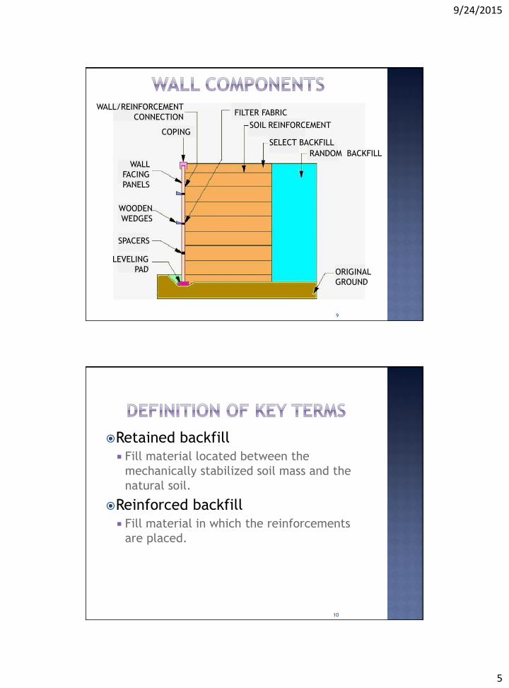
Types:
Segmental precast concrete panels
cruciform, square, rectangular, diamond,
or hexagonal geometry.
53

9/24/2015
26
Types:
Segmental precast concrete panels
cruciform, square, rectangular, diamond,
or hexagonal geometry.
Dry cast modular block wall (MBW) units
Relatively small, squat concrete units that
have been specially designed and
manufactured for retaining wall
applications.
Full height cores are filled with aggregate
during erection.
54
Metallic Facings
Appropriate in structures where difficult
access or difficult handling requires lighter
facing elements.
Welded Wire Grids and Twisted Wire
Can be bent up at the front of the wall to form
the wall face.
Gabion Facing
Rock-filled wire baskets can be used as facing
with reinforcing elements consisting of welded
wire mesh, welded bar-mats, geogrids,
geotextiles or the double-twisted woven mesh.
55

9/24/2015
27
56
57

9/24/2015
28
Facings using welded wire or gabions Disadvantages uneven surface, exposed backfill materials,
more tendency for erosion of the retained soil, possible shorter life from corrosion of the wires, and more susceptibility to vandalism.
Can be countered by providing shortcrete or by hanging facing panels on the exposed face and compensating for possible corrosion.
Advantages low cost, ease of installation, design
flexibility, good drainage that provides increased stability, and possible treatment of the face for vegetative and other architectural effects.
58
Geosynthetic Facing Looped around at the facing to form the
exposed face of the retaining wall.
Susceptible to ultraviolet light degradation, vandalism and damage due to fire.
Alternately, a geosynthetic grid used for soil reinforcement can be looped around to form the face of the completed retaining structure.
Vegetation can grow through the grid structure to provide both ultraviolet light protection for the geogrid and a pleasing appearance.
59

9/24/2015
29
60
Vegetation growing through
the grid structure
Postconstruction Facing
For wrapped faced walls, the facing can be
attached after construction of the wall by
shortcreting, cast-in-place concrete or attaching
prefabricated facing panels made of concrete,
wood, or other materials.
Adds cost but is advantageous where significant
settlement is anticipated.
61

9/24/2015
30
62
Shotcreting Cast In-Place Concrete
Two types of steel reinforcements
are in current use:
Steel strips
Ribbed top and bottom
Steel grids
Welded wire grid
Some MBW systems use steel grids with 2
longitudinal wires.
63

9/24/2015
31
64
Welded Wire GridSteel strips
Most MBW systems use geosynthetic
reinforcement, principally geogrids.
High Density Polyethylene (HDPE)
geogrid.
PVC coated polyester (PET) geogrid.
Geotextiles
65

9/24/2015
32
Require high quality backfill for:
durability, good drainage,
constructability, and good soil
reinforcement interaction.
In most cases a material with high
friction characteristics is specified and
required.
generally eliminate soils with high clay
contents.
66
Lower quality backfills could be used
for MSEW structures.
However, a high quality granular
backfill has the advantages of
being free draining, providing better
durability for metallic reinforcement,
and requiring less reinforcement,
increased rate of wall erection and
improved maintenance of wall
alignment tolerances.
67

9/24/2015
33
All joints are covered with a
polypropylene (PP) geotextile strip
to prevent the migration of fines
from the backfill.
68
Site Exploration
Feasibility of using any type of earth retention
system depends on the existing topography,
subsurface conditions, and soil/rock
properties.
Perform a comprehensive subsurface
exploration program to evaluate site stability,
settlement potential, need for drainage,
among others.
Investigations must be conducted to locate and
test locally available materials that can be
used for backfill with the selected system.
69

9/24/2015
34
Field Reconnaissance Preliminary subsurface investigation,
consists in collecting data relating to subsurface conditions and making a field visit to obtain data on: Limits and intervals for topographic cross
sections. Access conditions for work forces and
equipment. Surface drainage patterns, seepage, and
vegetation characteristics. Surface geologic features. The extent, nature, and locations of existing
or proposed below-grade utilities and substructures.
Available right-of-way. Areas of potential instability.
70
Subsurface Exploration
Soil soundings, borings, and test pits.
Minimum guidelines for subsurface
exploration:
Soil borings should be performed at intervals
of:
30 m (100 ft) along the alignment of the
soil-reinforced structure
45 m (150 ft) along the back of the
reinforced soil structure
71

9/24/2015
35
Causes for problems in projects
often traced to inadequate subsurface
exploration programs that did not disclose local
or significant areas of soft soils causing local
differential settlement and distress to the facing
panels.
Select backfill is to be obtained from on-site
sources
Extent and quality must be fully explored to
minimize contractor claims for changed
conditions.
72
Laboratory Testing
Soil samples should be visually examined
and appropriate tests performed for
classification according to the Unified
Soil Classification System (ASTM D 2488-
69).
Test results will provide:
Necessary information for planning
degradation protection measures.
Will help in the selection of reinforcement
elements with adequate durability.
73
9/24/2015
36
Structure Selection Factors
The major factors that influence the selection of an MSE alternative for any project:
Geologic and topographic conditions.
Environmental conditions.
Size and nature of the structure.
Aesthetics.
Durability considerations.
Performance criteria.
Availability of materials
Experience with a particular system or application.
Cost.74
Geologic and Topographic Conditions
Where soft compressible soils are
encountered, preliminary stability analyses
must be made to determine if sufficient
shear strength is available to support the
weight of the reinforced fill.
Where these conditions are not satisfied,
ground improvement techniques must be
considered to increase the bearing capacity
at the foundation level.
75

9/24/2015
37
Ground improvement techniques
include but are not limited to:
Excavation and removal of soft soils and
replacement with a compacted structural
fill.
Use of lightweight fill materials
In situ densification by dynamic compaction
or improvement by use of surcharging with
or without wick drains.
Construction of stone columns.
76
Environmental Conditions
Primary environmental issue: Aggressiveness of the in situ ground regime
that can cause deterioration to the reinforcement.
Post construction changes must be considered where de-icing salts or fertilizers are subsequently used.
A secondary environmental issue: Site accessibility
lightweight facings such as metal skins, modular blocks (MBW), or the use of geotextile or geogrid wrapped facings and vegetative covers
77

9/24/2015
38
Size and nature of structure Theoretically there is no upper limit to
the height of MSEW that can be constructed.
The lower limit to height is usually dictated by economy.
Practical limits are often dictated by: economy
available R.O.W.
tensile strength of commercially available soil reinforcing materials.
78
Aesthetics
Precast concrete facing panels may be
cast with an unlimited variety of texture
and color.
Modular block wall facings are often
comparable in cost to precast concrete
panels.
MBW facings may be manufactured in
color and with a wide variety of surface
finishes.
79

9/24/2015
39
Questionable Applications MSE walls should not be used under the
following conditions: When utilities other than highway drainage
must be constructed within the reinforced zone where future access for repair would require the reinforcement layers to be cut.
With galvanized metallic reinforcements exposed to surface or contaminated ground water.
When floodplain erosion may undermine the reinforced fill zone.
80
Working Stress analyses
Limit Equilibrium analyses
Check of the overall stability of the
structure.
Deformation Evaluations
Evaluation of the anticipated performance
of the structure with respect to horizontal
and vertical displacement
81

9/24/2015
40
Selecting the location for
reinforcement.
Checking that stresses in the
stabilized soil mass are compatible
with the properties of the soil and
inclusions.
Evaluating local stability at the level
of each reinforcement.
Predicting progressive failure.
82
Types of stability that must be
considered:
External stability
Involves the overall stability of
the stabilized soil mass
considered as a whole and is
evaluated using slip surfaces
outside the stabilized soil mass.
83

9/24/2015
41
Types of stability that must be considered: Internal stability analysis
Evaluation of potential slip surfaces within the reinforced soil mass.
Combined stability analysis
For when the critical slip surface is partially outside and partially inside the stabilized soil mass.
84
Influence and variations in the type of
reinforcement on the performance of the
structure can be evaluated.
Horizontal analysis is done so that the
usual factors of safety against external or
internal stability failure will ensure that
deformations will be within tolerable
limits.
Vertical deformation analyses are
obtained from conventional settlement
computations.85

9/24/2015
42
State of stress for external stability
Assumed to be equivalent to a Coulomb
state of stress with a wall friction angle
δ equal to zero.
State of stress for internal stability
A variable state of stress varying from a
multiple of Ka to an active earth
pressure state.
86
For external stability
The method assumes an earth pressure
distribution, consistent with the method
used for inextensible reinforcements.
For internal stability
A Rankine failure surface is considered,
because the extensible reinforcements
can elongate more than the soil, before
failure.
87

9/24/2015
43
Potential external failure
mechanisms:
Sliding on the base.
Limiting the location of the resultant of
all forces.
Bearing capacity.
Deep seated stability
rotational slip-surface or slip along a
plane of weakness.
88
89
Sliding

9/24/2015
44
90
Overturning (eccentricity)
91
Bearing Capacity

9/24/2015
45
92
Deep Seated Stability (Rotational)
External stability evaluations treat
the reinforced section as a
composite homogeneous soil mass.
Evaluate the stability according to
conventional failure modes for
gravity type wall systems.
93

9/24/2015
46
94
Must be defined by the designer:
Wall height, batter.
Soil surcharges, live load surcharges, dead load surcharges, etc.
Seismic loads.
Engineering properties of foundation soils (γ, c, φ).
Engineering properties of the reinforced soil volume (γ, c, φ).
Engineering properties of the retained fill (γ, c, φ).
Groundwater conditions.
95

9/24/2015
47
Should reflect site conditions and agency or AASHTO code requirements.
External stability factors of safety (Sliding, bearing capacity location of resultant force).
Global stability factor of safety.
Maximum differential settlement.
Maximum horizontal displacement.
Seismic stability factor of safety.
Design life
96
Process begins by adding the
required embedment to the wall
height to determine the design
heights for each section.
Preliminary length of reinforcement
is chosen to be greater than 0.7H
and 2.5 m.
H - design height of the structure.
97

9/24/2015
48
Structures with sloping surcharge
fills or other concentrated loads,
generally require longer
reinforcements for stability, often
from 0.8H to 1.1H.
98
Customarily designed on a project-
specific basis.
Most agencies use a line-and-grade
contracting approach, with the contractor
selected providing the detailed design.
However, standard designs can be
developed and implemented by an agency
for MSEW structures.
Similar to standard concrete cantilever wall
designs used by many agencies.
99

9/24/2015
49
Require generic designs and generic
materials.
Generic designs require definition of:
wall geometry and surcharge loads
soil reinforcement strength
structure height limit
Modular block wall (MBW) unit properties of
width and batter.
100
Definition of generic material properties
for the standard designs requires the
development of an approved product list
for MBW units, soil reinforcement and
MBW unit-soil reinforcement
combinations.
The combinations require a separate
approved product list.
An additional requirement for MBW units
is an approved manufacturing quality
control plan on file with the agency. 101

9/24/2015
50
102Figure 9: Design Cross Section
103
Reinforcement layout table from
the MN/DOT

9/24/2015
51
MSE wall contracted using two approaches: Agency or material supplier designs system components, drainage details, erosion
measures, and construction execution explicitly specified in the contracting documents
Performance or end-result approach Uses approved or generic systems or
components, with lines and grades noted on the drawings and geometric and design criteria specified.
104
This approach includes the development of a detailed set of plans and material specifications in the bidding documents.
Advantage
The complete design, details, and material specifications can be developed and reviewed over a longer design period.
Disadvantage
For alternate bids, additional sets of designs and plans must be processed.
Newer and potentially less expensive systems or components may not be considered during the design stage.
105

9/24/2015
52
Fully detailed plans shall include:
Plan and Elevation Sheets
Plan view.
Elevation views.
Length, size, and type of soil reinforcement.
Panel and MBW unit layout and the designation of the type or module.
Internal drainage alignment, elevation, and method of passing reinforcements around such structures.
Cross sections.
Limits and extent of reinforced soil volume.
All construction constraints.
Payment limits and quantities.
106
Facing/Panel Details Facing details for erosion control, reinforced
slopes, and all details for facing modules.
All details of the architectural treatment or surface finishes.
Drainage Facilities/Special Details All details for construction around drainage
facilities, overhead sign footings, and abutments.
All details for connection to traffic barriers, copings, parapets, noise walls, and attached lighting.
All details for temporary support including slope face support where warranted.
107

9/24/2015
53
Design Computations
Plans shall be supported by detailed
computations for internal and external stability
and life expectancy for the reinforcement.
Geotechnical Report
Engineering properties of the foundation soils.
Engineering properties of the reinforced soil.
Engineering properties of the fill or in situ soil
behind the reinforced soil mass.
Groundwater or free water conditions and
required drainage schemes if required
Construction Specifications
108
Often referred as "line and grade" or "two line drawing"
The agency prepares drawings of the geometric requirements for the structure or reinforced slope and material specifications for the components or systems that may be used.
The components or systems that are permitted are specified or are from a pre-approved list maintained by the agency, from its prequalification process.
Performed by trained and experienced staff.
109

9/24/2015
54
Advantage
The system specification approach lessens
engineering costs and manpower for an
agency and transfers some of the project's
design cost to construction.
Disadvantages
Agency engineers may not fully understand
the technology at first, therefore may not
be fully qualified to review and approve
construction modifications.
Complex phasing and special details are not
addressed until after the contract has been
awarded.110
As part of the contract documents: Geometric RequirementsPlan and elevation of the areas to be
retained.
Typical cross section.
Elevation view of each structure.
Location of utilities and signs.
Construction constraints.
Mean high water level, design high water level, and drawdown conditions where applicable.
111

9/24/2015
55
Geotechnical Requirements
The same as in Agency or Supplier
Design except that the design
responsibility is delineated as to areas
of contractor/supplier and agency
responsibility.
112
Structural and Design Requirements Reference to specific governing sections of
the agency design manual, construction specifications and special provisions.
Magnitude, location, and direction of external loads.
Limits and requirements of drainage features.
Slope erosion protection requirements for reinforced slopes.
Size and architectural treatment of concrete panels for MSE walls.
113

9/24/2015
56
Performance Requirements
Tolerable movement of the structure both
horizontal and vertical.
Tolerable face panel movement.
Monitoring and measurement requirements.
114
115

9/24/2015
57
Visual simulation Proposed MSE wall
Highway construction
Los Angeles
116
Video from You Tube for MSE wall
construction
https://www.youtube.com/watch?v=HIeBFF
mwis4
Contact information
(787) 832-4040
X6342 (office extension)
X3434 (civil engineering department)
117

9/24/2015
58
Elias, V., Christopher, B., Berg, R. (2001). Mechanically Stabilized Earth Walls and Reinforced Soil Slopes Design and Construction Guidelines. FHWA-NHI-00-043. Washington, D.C. :National Highway Institute.
http://www.tencate.com/pt/lam/Images/bro_mse0208_tcm31-10770.pdf.
http://www.dot.state.oh.us/Divisions/ConstructionMgt/OnlineDocs/2009MOP/SS%20840,%20850,851,%20S-1015/SS-840/SS.htm
http://www.tensarcorp.com/Systems-and-Products/Ares-Retaining-Wall-Systems
http://www.terrasiteco.com/construction-services/
119
http://www.geostructures.com/solutions/structures-walls/retaining-walls
https://teddywanders.wordpress.com/2013/06/28/yangsan-site-visit-geosynthetics-course/
http://www.ensolretaining.com/portfolio.php?do=hmc
https://www.rocscience.com/usage/use/4/Retaining-Walls
http://www.earthteccorp.com/
http://www.tencate.com/pt/lam/Images/bro_mse0208_tcm31-10770.pdf
http://www.icainversiones.com/?cat=1004..
120

11/10/15
1
Dr. Beatriz CamachoAssociate Professor
Department of Civil Engineering and Surveying
University of Puerto Rico at Mayagüez
1
�External stability Design Process�Internal stability Design Process
2

11/10/15
2
�Reinforced section for external stability evaluations treated as:¡ a composite homogeneous soil mass.
�Stability evaluated according to conventional failure modes for gravity type wall systems.
3
4
For ASD Method

11/10/15
3
5
Basic Design Steps for MSE Walls
6
Basic Design Steps for MSE Walls

11/10/15
4
7
Basic Design Steps for MSE Walls
� Important points regarding LRFD methodology to prevent any confusion in application of the various theories and equations presented:
¡ The symbol φ (phi) is used for both the¢ soil friction angle and ¢ LRFD resistance factor.
¡ The symbol γ (gamma) is used for both ¢ soil unit weight and ¢ LRFD load factor.
8
LRFD METHOD
11/10/15
5
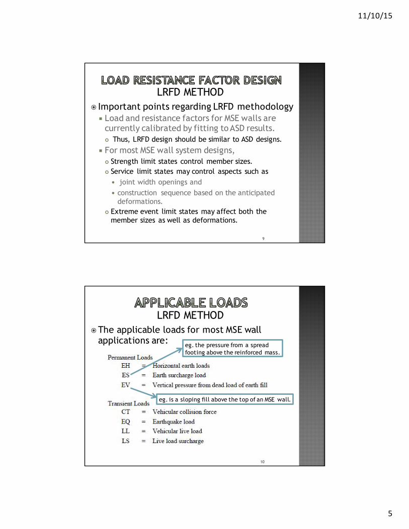
� Important points regarding LRFD methodology¡ Load and resistance factors for MSE walls are
currently calibrated by fitting to ASD results.¢ Thus, LRFD design should be similar to ASD designs.
¡ For most MSE wall system designs, ¢ Strength limit states control member sizes. ¢ Service limit states may control aspects such as
� joint width openings and � construction sequence based on the anticipated
deformations. ¢ Extreme event limit states may affect both the
member sizes as well as deformations.
9
LRFD METHOD
�The applicable loads for most MSE wall applications are:
10
LRFD METHOD
eg. the pressure from a spread footing above the reinforced mass.
eg. is a sloping fill above the top of an MSE wall.

11/10/15
6
11
LRFD METHOD
CT=Vehicular collision force
12
LRFD METHOD

11/10/15
7
� In general, AASHTO’s guidance can be applied by¡ using minimum load factors if permanent loads
increase stability and ¡ use maximum load factors if permanent loads
reduce stability. ¡ For simple walls, e.g., level backfill with or
without surcharges due to traffic, or sloping backfill, the load factor (minimum or maximum) to use for a particular stability check may be readily identifiable.
13
LRFD METHOD
14
LRFD METHOD

11/10/15
8
15
LRFD METHOD
�External Stability ¡ Limiting Eccentricity¡ Sliding¡ Bearing Resistance
� Internal Stability¡ Tensile Resistance of Reinforcement¡ Pullout Resistance of Reinforcement¡ Structural Resistance of Face Elements¡ Structural Resistance of Face Element
Connections
Specific checks for the strength limit states required for MSE wall design

11/10/15
9
� Service Limit States for MSE walls¡ External Stability
¢ Vertical Wall Movements¢ Lateral Wall Movements
� Global Stability of MSE walls¡ Overall Stability¡ Compound Stability
Specific checks for the service limit states and global stability required for MSE wall design

11/10/15
10
�Geometry¡ Wall height,¡ Wall batter,¡ Backslope¡ Toe slope
�Loading conditions¡ Soil surcharges,¡ live load surcharges, ¡ dead load surcharges, ¡ loads from adjacent structures¡ Seismic loads.
19
Must be defined by the designer (owner):
�Performance Criteria¡ Design code¡ Maximum tolerable differential settlement ¡ Maximum tolerable horizontal displacement ¡ Design life¡ Construction Constrains
20
Must be defined by the designer (owner):

11/10/15
11
�Existing and proposed topography� Subsurface conditions across the site
¡ Engineering properties of foundation soils (γf, c’f, φ’f, cu).
¡ Groundwater conditions.�Reinforced wall fill
¡ Engineering properties of the reinforced soil volume (γr, φr).
�Retained backfill¡ Engineering properties of the retained fill (γb,
cb, φb), cohesion usually assumed cero
21
Must be defined by the designer (owner):
�Process begins by determining ¡ required embedment and ¡ Final exposed wall height
(combination of these two = design height, H)
22

11/10/15
12
Horizontal slope
Minimum depth
Slope in Front of wall=Sloping toe
Minimum depth

11/10/15
13
�Preliminary length of reinforcement is chosen to be the greater of:¡ 0.7H and ¡ 2.5 m (8ft)
�Structures with sloping surcharge fills or other concentrated loads, ¡ generally require longer reinforcements for
stability, ¡ often on the order of 0.8H to 1.1H.
25
�Reinforcement should be uniform¡However, it is recommended to add an
extra 3ft (0.9m) on the upper two layers of soil reinforced
26(Where post-construction movement occurs)

11/10/15
14
�Computations for walls with a vertical face¡ Made assuming that wall mass acts as a rigid
body with earth pressures developed on a vertical pressure plane arising from the back end of the reinforcements.
¡ This is because, when properly designed, the wall facing and the reinforced soil act as a coherent block with lateral earth pressures acting on the back side of that block
27
�The primary sources of external loading on an MSE wall are ¡ the earth pressure from the retained backfill
behind the reinforced zone and ¡ any surcharge loadings above the reinforced
zone.
�Thus, the loads for MSE walls may include:¡ loads due to horizontal earth pressure(EH), ¡ vertical earth pressure (EV), ¡ live load surcharge (LS), and ¡ earth surcharge (ES),¡ water (WA) and seismic (EQ) should also be
evaluated if applicable28

11/10/15
15
29
Forces acting on wall with horizontal backslope and traffic surcharge (Earth pressure / eccentricity)
30
Forces acting on wall with sloping backslope
Earth pressure/eccentricity
11/10/15
16
31
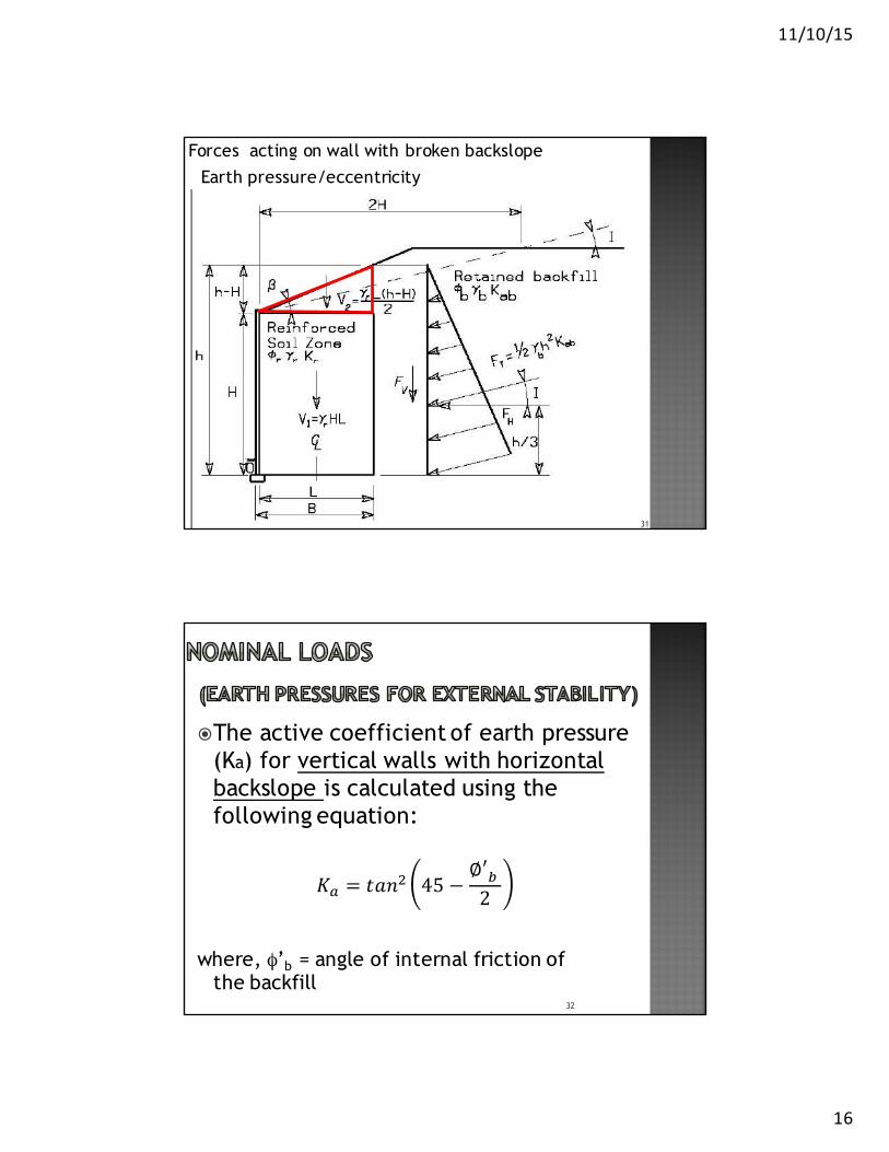
Forces acting on wall with broken backslope
Earth pressure/eccentricity
32
�The active coefficient of earth pressure (Ka) for vertical walls with horizontal backslope is calculated using the following equation:
𝐾" = 𝑡𝑎𝑛' 45 −∅′-2
where, φ’b = angle of internal friction of the backfill

11/10/15
17
�For vertical wall with a surcharge slope:
33
Where:δ = angle of friction between retained backfill and reinforced soil, set equal to βθ = 90o for vertical, or near (<10o) vertical wallsΓ= next slide
34
�For vertical wall with a surcharge slope (cont..):

11/10/15
18
�For vertical wall with broken backslope:¡ Same equations as before, but:
¢ Design β angle and interface angle δ = I
I=Atan (012)'2
35
�For battered wall –inclined front face equal to or greater than 10 degrees from vertical , Ka calculated with:¡ Same equations as before ¡ Where:
¢ θ - face inclination from horizontal¢β - surcharge slope angle¢The wall friction angle δ is assumed to be
equal to β.
36

11/10/15
19
�Should be treated as uniform surcharge live load of not less than 2.0 ft (0.6m).¡ For external and internal stability, walls
parallel to traffic, the equivalent height of soil, heq = 2.0 ft.
¡ For retaining wall abutments use values on the table
38

11/10/15
20
�Consider¡ Sliding on base¡ Limiting eccentricity (overturning)¡ Bearing resistance¡ Overall/global stability
�Resistance factor used:
39
φ =φ =
φ =
φ =
40
Sliding

11/10/15
21
�Check the preliminary sizing with respect to sliding at the base layer:
𝐶𝐷𝑅 =𝑅7𝑃9
≥ 1.0
where, CDR=capacity to demand ratioRr = factored sliding resistancePd = factored driving force
41
�Calculate thrust:¡Wall with horizontal backslope
¡Wall with uniform surcharge:
42
𝐹? =12 𝐾"- 𝛾-𝐻
'
𝐹' = 𝐾"-𝑞𝐻where,
F1 = retained backfill resultantF2 = resultant due to uniform surchargeKab = active earth pressure coefficient for the
retained backfill γb= moist unit weight of the retained backfillH = height of the retaining wallq = uniform live load surcharge = (γb)(heq)

11/10/15
22
�Calculate thrust:¡Wall with sloping backfill:
43
𝑭𝑻 =𝟏𝟐𝑲𝒂𝒃 𝜸𝒃𝒉𝟐
whereFT = nominal retained backfill resultant per unit
width,Kab = active earth pressure coefficient for the
sloping backfill h = total height of wall and slope at the back of
the reinforced zoneh = H + L tan β
�Calculate the nominal and factored horizontal driving forces:¡Wall with horizontal backslope and uniform
live load surcharge:
44
M𝑭 =𝑭𝟏 + 𝑭𝟐
Horizontal backslopeUniform surcharge

11/10/15
23
�Calculate the nominal and factored horizontal driving forces:¡Wall with sloping backfill:
45
Use the maximum EH load factor (γEH= 1.50) in these equations because it creates the maximum driving force effect for the sliding limit state.
�Determine the most critical frictional properties at the base. Choose the minimum φ for:¡ Sliding along the foundation soil (φ’f).¡ Sliding along the reinforced backfill (φ’r).¡ For sheet type reinforcement
¢ sliding along the weaker of the upper and lower soil-reinforcement interfaces.
¢ soil-reinforcement friction angle (ρ) = 2/3 tan φ’ror measured with direct shear test.
46

11/10/15
24
�Calculate nominal components of resisting force and factored resisting force per unit length of wall :¡ For horizontal backslope and uniform live
load surcharge: (surcharge not considered because increases stability)
where,µ = min soil friction angle [tan φ’f , tan φ’r , or (for continuous reinforcement) tan ρ]
47
𝑹𝒓 = 𝜸𝑬𝑽𝑽𝟏 𝐱 𝝁
�Calculate nominal components of resisting force and factored resisting force per unit length of wall :¡ For sloping backfill:
External loads that increase sliding resistance considered ONLY if they are PERMANENT
48
𝑹𝒓 = 𝜸𝑬𝑽(𝑽𝟏+𝑽𝟐) + 𝜸𝑬𝑯(𝑭𝒔𝒊𝒏𝜷) 𝝁
Use the minimum EV load factor (γEV = 1.00) in these equations because it results in minimum resistance for the sliding limit state.

11/10/15
25
�Check the capacity demand ratio:
𝑪𝑫𝑹 =𝑹𝒓𝑷𝒅
≥ 𝟏. 𝟎
�If CDR < 1.0 increase length of reinforcement (L) and repeat
49
� Is a strength limit state check
�Weight and width of wall neglected
�Only considers live load above retained backfill
50
Limiting Eccentricity

11/10/15
26
51
Earth pressures/eccentricity; horizontal backslope with traffic surcharge
Applies live load (surcharge) above retained backfill only
52
Distance between resultant of vertical forces (R) and the center of the reinforced zone
Kabq

11/10/15
27
53
Obtained from sum of overturning and resisting moments about the bottom center of the base compared with sum of vertical forces
𝑒 =∑𝑀b − ∑𝑀c
∑𝑉
Kabq
Bottom center of the base
54
Kabq
For wall with horizontal backslope and traffic surcharge
γ‘s are load factors, EH=horizontal earth, LS=live surcharge

11/10/15
28
55
For wall with sloping backfill
e
�Check the eccentricity criteria:¡ For wall base over soil
𝒆𝒎𝒂𝒙 =𝑳𝟒
¡ For wall base over rock
𝒆𝒎𝒂𝒙 =𝟑𝟖𝑳
56

11/10/15
29
�For each strength limit group ¡ e < emax
�If e > emax then longer length reinforcement is needed
57
58
Calculation of vertical stress σv at the foundation level
Sloping backslope

11/10/15
30
�Two modes exist:¡ general shear failure ¡ local shear failure
¢Characterized by punching or squeezing of the foundation soil when soft or loose soils exist the below wall
59
Bearing Capacity
�This analysis require two types of calculations:¡ Strength limit state and
¢ Check soil strength
¡ Service limit state¢ Used in settlement calculations
60

11/10/15
31
�To prevent bearing capacity failure¡ The factored vertical pressure at the base
of the wall (qR), should not exceed the factored bearing resistance of the foundation soil (quniform)
61
𝒒𝑹 ≥ 𝒒𝒖𝒏𝒊𝒇𝒐𝒓𝒎
62
Kabq
Applies live load (surcharge) above both:reinforced zone and retained backfill
Also assumes: σv uniform throughout length = L-2e

11/10/15
32
�The uniform vertical pressure (σv) at the base of the wall is defined as:
¡ ΣV = summation of vertical forces¡ L = reinforcement length¡ eB = eccentricity for bearing calculation
(different from limit eccentricity check)
63
�Calculate eccentricity, eB, of the resulting force at base of wall¡ For wall with horizontal backslope and
uniform live load surcharge centered about reinforced zone:
64
11/10/15
33
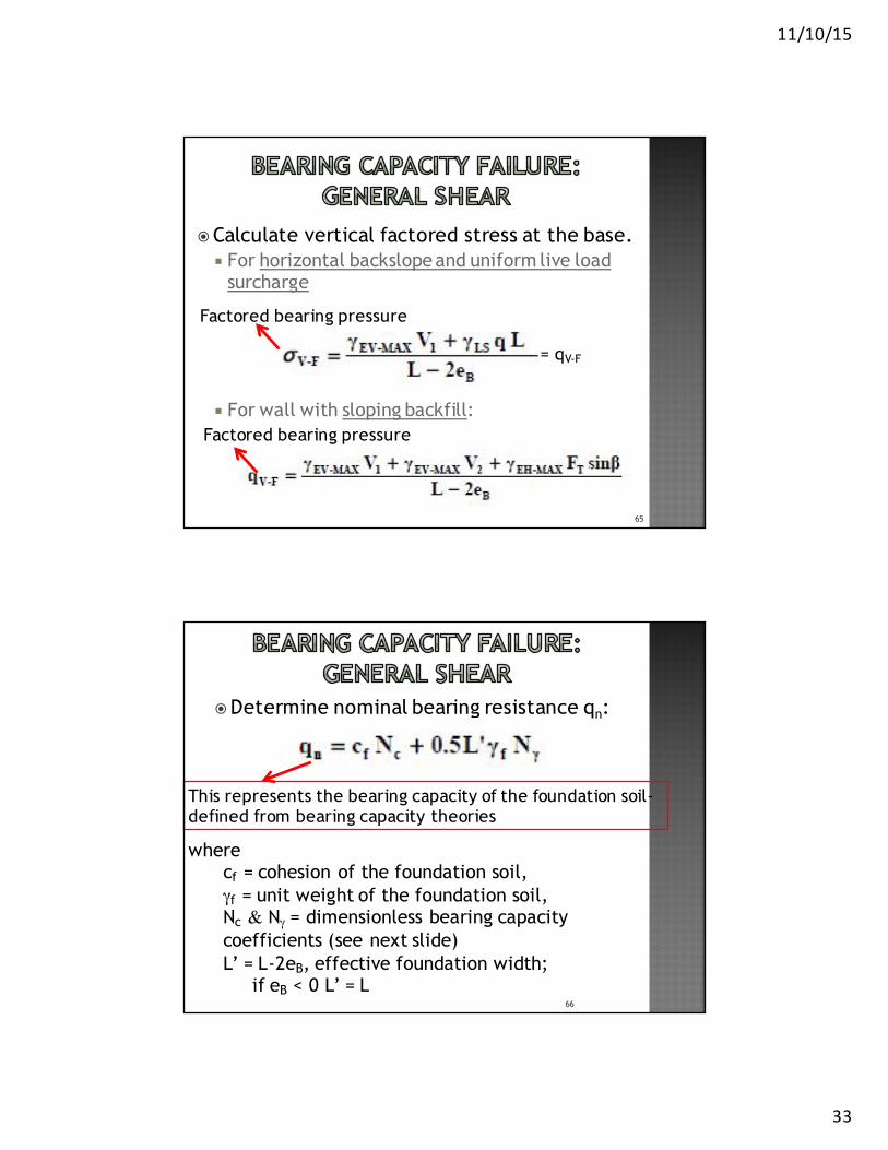
�Calculate vertical factored stress at the base. ¡ For horizontal backslopeand uniform live load
surcharge
¡ For wall with sloping backfill:
65
Factored bearing pressure
Factored bearing pressure
= qV-F
�Determine nominal bearing resistance qn:
66
wherecf = cohesion of the foundation soil,γf = unit weight of the foundation soil,Nc & Nγ = dimensionless bearing capacity coefficients (see next slide)L’ = L-2eB, effective foundation width;
if eB < 0 L’ = L
This represents the bearing capacity of the foundation soil-defined from bearing capacity theories

11/10/15
34
Bearing resistance factors
Bearing resistance factors (cont…)

11/10/15
35
�Determine factored bearing resistance qR:𝑞c = ∅𝑞}
69
whereφ = resistance factor for MSE = 0.65
�Check bearing capacity criteria:
𝑞c ≥ 𝑞~1�
qV-F can be decreased and qR increased by increasing the length of the reinforcement
�To prevent local shear of structures on weak cohesive soil:
𝛾7𝐻 ≤ 3𝑐�
¡ If adequate support conditions cannot be achieved, ¢ soft soils should be removed or¢ ground improvement of the foundation soils
should be considered. 70
Nominal unit weight of
reinforced fill
Nominal total stress cohesion
of the foundation soil
Wall height

11/10/15
36
71
�Determined using¡ rotational analyses or wedge analyses¡ Computer programs
�Based on Limit Equilibrium Analysis the reinforced soil wall is considered as a rigid body and only failure surfaces outside the reinforced mass are analyzed.
� If the minimum safety factor (FS) is less than 1.3, increase the reinforcement length or improve the foundation soil.
72

11/10/15
37
�During an earthquake, the retained fill exerts a dynamic horizontal thrust, PAE, on the MSE wall in addition to the static thrust.
�Force PAE can be evaluated by the pseudo-static Mononobe-Okabe analysis and added to the static forces acting on the wall (weight, surcharge, and static thrust).
73
�The dynamic stability with respect to external stability is then evaluated. ¡ Allowable minimum dynamic safety factors
are assumed as 75 percent of the static safety factors.
𝐹𝑆9�}"��� = 0.75𝐹𝑆��"���
74

11/10/15
38
�The seismic external stability evaluation:¡ Select a peak horizontal ground acceleration
based on the design earthquake. ¡ Calculate the maximum acceleration Am
developed in the wall:
¢ where:� A = max. ground acceleration coefficient,
AASHTO, Division 1A.� Am = max. wall acceleration coefficient at
the centroid of the wall mass.
75
�Calculate the horizontal inertia force PIR and seismic thrust PAE.
�Add to the static forces acting onthe structure, 50 percent of theseismic thrust PAE and the fullinertial force PIR.
76

11/10/15
39
�For structures with sloping backfills¡ The inertial force (PIR) and the dynamic
horizontal thrust (PAE) shall be based on a height H2 near the back of the wall mass determined as follows:
77
�For structures with sloping backfills� PIR for sloping backfills should be
calculated as follows:
� Pir = inertial force caused by acceleration of the reinforced backfill
� Pis = inertial force caused by acceleration of the sloping soil surcharge above the reinforced backfill.
78

11/10/15
40
�Total seismic earth pressure coefficient KAE based on the Mononobe-Okabe general expression is computed from:
¡ Where:¢ I = the backfill slope angle = β ¢ ξ = arc tan (Kh/1 - Kv) ¢φ = the soil angle of friction ¢θ = the slope angle of the face
79
�To complete the design:¡ Evaluate sliding stability, eccentricity
and bearing capacity as detailed previously.
¡ Check:¢Computed safety factors are equal to
or greater than 75 percent of the minimum static safety factors
¢Eccentricity falls within L/3 for both soil and rock.
80
11/10/15
41
�Should define the CDR as previously explained for the different failure modes but considering the additional dynamic loading
81
�Conventional settlement analyses should be carried out to ensure:¡ Immediate consolidation and secondary
settlement of the wall are less than the performance requirements of the project.
82

11/10/15
42
�Significant total settlements at the end of construction indicate that the planned top of wall elevations need to be adjusted. ¡ Can be accomplished by increasing the
top of wall elevations during design, by delaying the casting of the top row of panels to the end of erection.
83
¡Where the anticipated settlements and their duration, cannot be accommodated by these measures, consider ground improvement techniques:¢wick drains, stone columns, and
dynamic compaction
84

11/10/15
43
85
Vibro replacement to form stone columns
86
Dynamic Compaction, Installation Process
Dynamic Compaction

11/10/15
44
87
Wick Drain
�Internal failure of MSE wall can occur in two ways:
¡ Failure by elongation or breakage of the reinforcement¢Tensile forces on the inclusions too large
¡ Failure by pullout¢Tensile forces in the reinforcement becomes
larger than pullout resistance
88

11/10/15
45
�Treated as a response of discrete elements in a soil mass. ¡ Deformations are controlled by the
reinforcements rather than total mass.
�Determines the reinforcement required,¡ In the development of the internal lateral
stress and ¡The assumption as to the location of the
most critical failure surface.
89
�Consists on determining:¡ maximum developed tension forces and
their location along a locus of critical slip surfaces.
¡ resistance provided by the reinforcements both in pullout capacity and tensile strength.
90

11/10/15
46
91
92

11/10/15
47
� Select a reinforcement type (inextensible or extensible).
� Select the location of the critical failure surface.
� Select a reinforcement spacing.� Calculate the maximum tensile force at each
reinforcement level, static and dynamic.� Calculate the maximum tensile force at the
connection to the facing.� Calculate the pullout capacity at each
reinforcement level.93
�Inextensible - Mostly metallic
94http://www.fhwa.dot.gov/publications/researc h/infra structure/ struc tures/11027/001 .cfm
Steel stripWire mesh

11/10/15
48
�Extensible - Mostly polymeric material
95http://www.fhwa.dot.gov/publications/researc h/infra structure/ struc tures/11027/001 .cfm
Geogrid
�Extensible - Mostly polymeric material
96
Geogrid
https://teddywanders.files.wordpress.c om/2013/06/cam00367.jpg

11/10/15
49
� It is assumed to coincide with the locus of maximum tensile force, Tmax.
�When failure develops, the reinforcement may elongate and be deformed at its intersection with the failure surface. ¡ The tensile force in the reinforcement would
increase and rotate. ¡ The component in the direction of the failure
surface would increase and the normal component may increase or decrease.
97
(Bilinear Surface)

11/10/15
50
(Linear Surface)
(Linear Surface)

11/10/15
51
�Using an economical design may be possible by varying the reinforcement density with depth.
�To provide a coherent reinforced soil zone, vertical spacing of primary reinforcement should not exceed 32 inches (800 mm )
101
�Ways to accomplish this for MSEW with segmental precast concrete facings:¡ Reinforcements consisting of strips, grids, or
mats:¢ Vertical spacing is maintained constant ¢ reinforcement density is increased with depth by
increasing the number and/or size of the reinforcements.
¡ Continuous sheet reinforcements, made of geotextiles or geogrids¢ Change the vertical spacing Sv.
102

11/10/15
52
�Low-to-medium-height walls (<16ft = 5m)¡ Usually constructed with one strength
geosynthetic
�Taller walls¡ Multiple strength geosynthetic
�Walls with modular blocks ¡ Sv-max = 2 times block depth (front face to back
face) or 32in. (810mm)¡ Top row limited to 1.5 block depth
103
�Large face units e.g. 3 ft x 3 ft gabions (9.0mx0.9m)¡ Vertical spacing (Sv) = face height
(i.e., 3 ft = 0.9m)
104

11/10/15
53
�The resulting Kr/Ka for inextensible reinforcements ratio decreases from the top of the wall to a constant value below 6 m (20 ft).
�Ratio of Kr/Ka obtained from figure in next slide
105
106
VARIATION OF Kr/Ka

11/10/15
54
�Once the ratio of K/Ka is obtained need to define Ka.
�For a vertical wall the earth pressure coefficient defined by Coulomb reduces to the Rankine equation:
107
�For wall face batters equal to or greater than 8 degrees from the vertical:
108

11/10/15
55
�Calculate at each reinforcement level the horizontal stresses σH
¡ Where:
109
Weight of the reinforced zone
Stress due to sloping backfill

11/10/15
56
� The supplemental factored horizontal pressure, Δσh, could be from a variety of sources. Two examples of supplemental horizontal pressures are as follows:
1. Horizontal pressures due to the horizontal (shear) stresses at the bottom of a spread footing on top of reinforced soil zone.
2. Horizontal pressures from deep foundation elements extending through the reinforced soil zone.
�Calculate maximum tension Tmax in each reinforcement layer per unit width based on the vertical spacing Sv
� σH, calculated at the level of the reinforcement, is at the center of the contributory height.¡ The contributory height is defined as the midpoint
between vertically adjacent reinforcement elevations, except for the top and bottom layers reinforcement.
112

11/10/15
57
�Calculate factored tensile resistance Tr𝑇7 = ∅𝑇"�
� Where ¡ φ = reduction factor for tensile resistance ¡ Tal = allowable tension force per unit width of
the reinforcement.
� Stability with respect to breakage of the reinforcements requires that:
TMAX ≤ Tr
114

11/10/15
58
� where:¡ b = the gross width of the strip, sheet or grid¡ Fy = yield stress of steel
¡ Ac = design cross section area of the steel, defined as the original cross section area minus corrosion losses anticipated to occur during the design life of the wall.
Resistance Factors φ for tensile resistance

11/10/15
59
� The following criteria must be satisfied:
¡ Where¢ FSPO = Safety factor against pullout ≥ 1.5. ¢ Tmax = Maximum reinforcement tension.¢ C = 2 for strip, grid, and sheet type
reinforcement. ¢ α = Scale correction factor.¢ F* = Pullout resistance factor.¢ Rc = Coverage ratio. ¢ γ Zp = The overburden pressure¢ Le = The length of embedment in the resisting
zone. 117
�The required embedment length in the resistance zone
� If the criterion is not satisfied¡ Reinforcement length has to be increased
and/or reinforcement with a greater pullout resistance per unit width must be used, or the vertical spacing may be reduced which would reduce Tmax.
118

11/10/15
60
�The total length of reinforcement, L, required is determined using:
�For MSEW with extensible reinforcement, vertical face and horizontal backfill
¡ Where:¢Z = depth to the reinforcement level
119
�For walls with inextensible reinforcement from the base up to H/2:
�For the upper half of a wall with inextensible reinforcements
120

11/10/15
61
� Elias, V., Christopher, B., Berg, R. (2001). Mechanically Stabilized Earth Walls and Reinforced Soil Slopes Design and Construction Guidelines. FHWA-NHI-00-043. Washington, D.C. :National Highway Institute.
122

9/24/2015
1
Design of Reinforced Slope (RSS)Dr. Beatriz Camacho
Professor
Department of Civil Engineering and Surveying
University of Puerto Rico at Mayaguez
1
Reinforced Soil Slopes (RSS)
• Incorporates multiple horizontal layers of geosynthetics or wire mesh that act as reinforcements for the soil with face inclinations of less than 70 degrees.
• By placing tensile reinforcing elements in the soil, the strength of the soil can be improved significantly such that the vertical face of the soil/reinforcement system is essentially self supporting.
• Can tolerate larger settlements than reinforced concrete walls.
2

9/24/2015
2
Reinforced Soil Slopes (RSS)
3
Reinforced Soil Slope using
Geogrids
Definition of key terms
• Geosynthetics▫ Polymeric materials
geotextiles, geomembranes, geonets, and geogrids.
The use of geotextiles in RSS started after noticing the beneficial effect in highway embankments over weak subgrades.
The first geotextile reinforced wall was constructed in France in 1971.
4
Geogrids
Geonets
9/24/2015
3
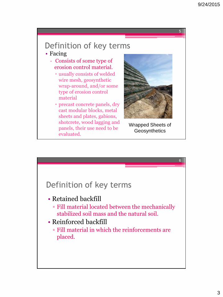
Definition of key terms • Facing
▫ Consists of some type of erosion control material.
usually consists of welded wire mesh, geosyntheticwrap-around, and/or some type of erosion control material
precast concrete panels, dry cast modular blocks, metal sheets and plates, gabions, shotcrete, wood lagging and panels, their use need to be evaluated.
5
Wrapped Sheets of
Geosynthetics
Definition of key terms
• Retained backfill▫ Fill material located between the mechanically
stabilized soil mass and the natural soil.
• Reinforced backfill▫ Fill material in which the reinforcements are
placed.
6

9/24/2015
4
Purposes for using reinforcement
in slopes• Improved stability for steepened slopes and
slope repair.
• Compaction aids, for support of construction equipment and improved face stability.
7
Purpose for using reinforcement in
slopes
• Principal purpose ▫ Construct an RSS embankment at an angle
steeper than could otherwise be safely constructed with the same soil. Roadways can also be widened over existing flatter
slopes without invading existing right-of-ways.
If repairing a slope failure, the new slope will be safer, and reusing the slide debris rather than importing higher quality backfill may result in substantial cost savings.
8

9/24/2015
5
Application for reinforced soil slope
9
For a New Construction
10
As a Wall Alternative
Application for reinforced soil slope

9/24/2015
6
11
For Road Widening
Application for reinforced soil slope
12
For Slide Repair
Application for reinforced soil slope

9/24/2015
7
Purpose for using reinforcement in
slopes• Second purpose
▫ To provide lateral resistance during compaction at the edges of a compacted fill slope.
Increased lateral resistance allows for an increase in compacted soil density which provides increased lateral confinement for the soil at the face.
13
Other Applications
• Upstream/downstream face improvements to increase height of dams.
• Permanent levees.
• Temporary flood control structures.
• Decreased bridge spans.
• Temporary road widening for detours.
• Prevention of surface sloughing during periods of saturation.
• Embankment construction with wet, fine-grained soils.
14

9/24/2015
8
Applications
15
Highway Embankment RSS to prevent surface
sloughing
Advantages
• Material and right-of-way savings.
• In some cases, RSS can be constructed at about one-half the cost of MSEW structures.
• The use of vegetated-faced reinforced soil slopes can be landscaped to blend with natural environments.
• Lower risk of long-term stability problems developing in the slopes due to more conservative designs.
16

9/24/2015
9
Disadvantages
• Requires large space behind the wall for internal and external stability.
• Suitable design criteria is required to address corrosion of steel reinforcing elements, deterioration of certain types of exposed facing elements and potential degradation of polymer reinforcement in the ground.
• Specifications and contracting practices have not been fully standardized.
• Requires a shared design responsibility between material suppliers and owners and greater input from agencies geotechnical specialists .
17
Relative Costs
• The economy must be assessed on a case-by-case basis, where use is not dictated by space constraints.
▫ An appropriate benefit to cost ratio analysis should be carried out.
▫ Guardrails or traffic barriers are often necessary for steeper embankment slopes and additional costs such as erosion control systems for slope face protection must be considered.
18

9/24/2015
10
Relative Costs• The factors to consider are as follows:
▫ Cut or fill earthwork quantities.
▫ Size of slope area.
▫ Average height of slope area.
▫ Angle of slope.
▫ Cost of nonselect versus select backfills.
▫ Temporary and permanent erosion protection requirements.
▫ Cost and availability of right-of-way needed.
▫ Horizontal and vertical alignment changes.
▫ Need for temporary excavation support systems.
▫ Maintenance of traffic during construction.
▫ Aesthetics.
▫ Requirements for guardrails and traffic barriers.
19
Relative Costs
• The bid cost of a specific RSS structure depends on the cost of:▫ Reinforcement - 45 to 65 % of total cost
▫ Backfill - 30 to 45 % of total cost
▫ Face treatment - 5 to 10 % of total cost
20
9/24/2015
11
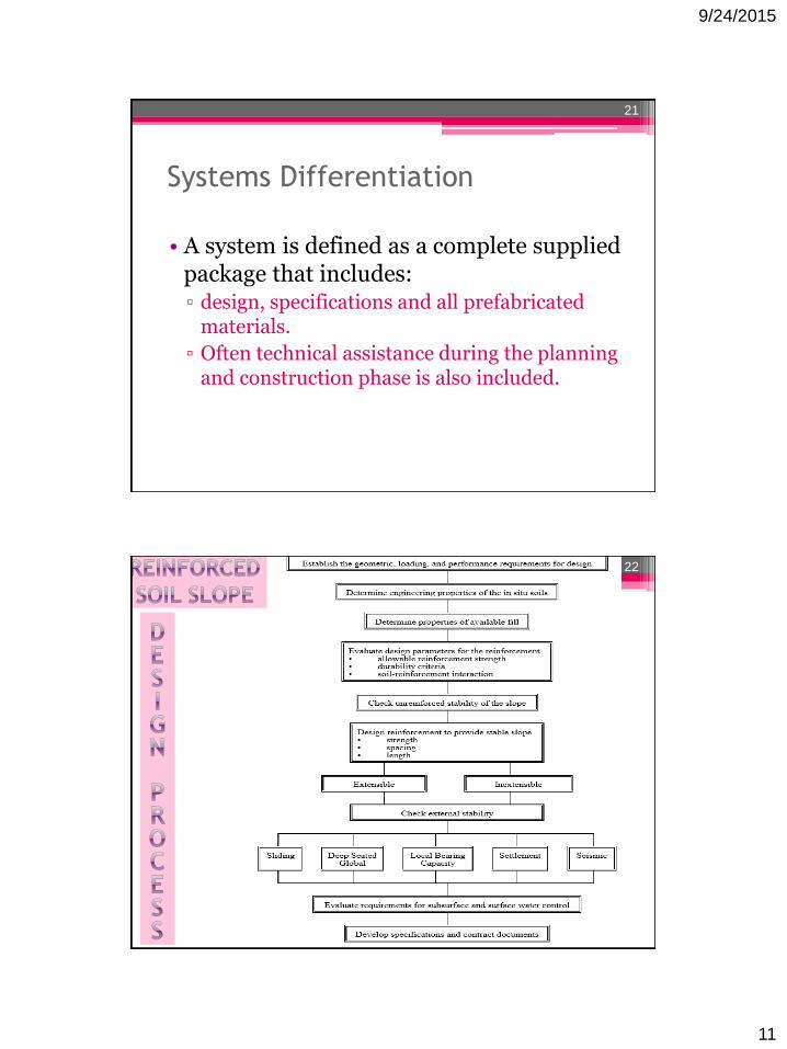
Systems Differentiation
• A system is defined as a complete supplied package that includes:▫ design, specifications and all prefabricated
materials.
▫ Often technical assistance during the planning and construction phase is also included.
21
22

9/24/2015
12
Types of Systems
• RSS systems can be described by:
▫ Reinforcement geometry
▫ Stress transfer mechanism
▫ Reinforcement material
▫ Extensibility of the reinforcement material
▫ Type of facing and connections
23
Reinforcement Geometry
• Three types that can be considered:
▫ Linear unidirectional
Strips: smooth or ribbed steel strips
Coated geosynthetic strips over a load-carrying fiber
▫ Composite unidirectional
Grids or bar mats characterized by grid spacing greater than 150 mm (6 inches).
▫ Planar bidirectional
▫ Continuous sheets of geosynthetics, welded wire mesh, and woven wire mesh.
24

9/24/2015
13
Reinforcement Material
• Metallic reinforcements▫ Typically of mild steel
Usually galvanized or epoxy coated.
• Nonmetallic reinforcements▫ Generally polymeric materials
polypropylene, polyethylene, or polyester
25
Reinforcement Extensibility
• Classes of extensibility:
▫ Inextensible
The deformation of the reinforcement at failure is much less than the deformability of the soil.
▫ Extensible
The deformation of the reinforcement at failure is comparable to or even greater than the deformability of the soil.
26

9/24/2015
14
Construction Materials:
Reinforcement Types
• Even though discrete strip type reinforcing elements can be used, the majority of the systems are constructed with continuous sheets of geosynthetics or wire mesh.
• Small, discrete micro reinforcing elements such as fibers, yarns, and microgrids have also been used.
27
Construction Materials:
Reinforced Fill Requirements• The recommended reinforced fill is limited
to low-plasticity, granular material
• However, with good drainage, careful evaluation of soil and soil-reinforcement interaction characteristics, field construction control, and performance monitoring, most indigenous soil can be considered.
28

9/24/2015
15
Reinforced Backfill Materials• Slopes constructed with a flexible face can
tolerate minor distortions that could result from settlement, freezing and thawing, or wet-drying of the backfill.
• Any soil meeting the requirements for embankment construction could be used in a reinforced slope system.
• A higher quality material offers less durability concerns for the reinforcement, and is easier to handle, place and compact, which speeds up construction.
29
Structure Selection Factors• Major factors that influence the selection of an
RSS alternative for any project include:
▫ Geologic and topographic conditions.
▫ Environmental conditions.
▫ Size and nature of the structure.
▫ Aesthetics.
▫ Durability considerations.
▫ Performance criteria.
▫ Availability of materials.
▫ Experience with a particular system or application.
▫ Cost
30

9/24/2015
16
Geologic and Topographic Conditions
• For RSS embankments the required foundation strength is somewhat less than for MSE walls and depends on the actual slope considered.
• If these conditions are not satisfied, ground improvement techniques must be considered. The techniques include but are not limited to:
▫ Excavation and removal of soft soils and replacement with a compacted structural fill.
▫ Use of lightweight fill materials.
▫ In situ densification by dynamic compaction or improvement by use of surcharging with or without wick drains.
▫ Construction of stone columns.
31
Environmental Conditions
• RSS construction with an organic vegetative cover must be carefully chosen to
▫ be consistent with native perennial cover that would establish itself quickly.
▫ thrive with available site rainfall.
32

9/24/2015
17
Size and nature of structure
• RSS may be cost effective in
▫ rural environments
where ROW restrictions exist or on widening projects where long sliver fills are necessary.
▫ urban environments
they should be considered where ROW is available, as they are always more economical than MSEW structures.
33
Aesthetics
• Outward face treatment▫ generally by vegetation
Initially more economical than the concrete facing used for MSE structures.
Maintenance costs may be considerably higher, and the long-term performance of many outward face treatments has not been established.
34

9/24/2015
18
Establishment of project criteria
• The engineer should consider each topic area at a preliminary design stage and determine appropriate elements and performance criteria.
• The process consists of:
▫ Consider all possible alternatives.
▫ Choose a system (MSEW or RSS).
▫ Consider facing options.
▫ Develop performance criteria.
▫ Consider effect of site on corrosion/degradation of reinforcements.
35
Facing Considerations
• The choice of slope facing may be controlled by climatic and regional factors.
• For structures of less than 10 m (33 ft) height with slopes of 1:1 or flatter
▫ a vegetative "green slope" can be usually constructed using an erosion control mat or mesh and local grasses.
▫ if vegetation cannot be established, armored slopes using natural or manufactured materials may be the only choice.
36

9/24/2015
19
Design Approach
• Determine the purpose for using reinforcement
• Design of Reinforcement for Compaction Aid
• Design of Reinforcement for Steepening Slopes and Slope Repair
• Computer-Assisted Design
• Evaluation of External Stability
37
Use Considerations
• Determine the purpose for using RSS:
▫ Improved stability for steepened slopes and slope repair.
▫ Compaction aids, for support of construction equipment and improved face stability.
38

9/24/2015
20
Use considerations
• Failure Modes
▫ Internal
Failure plane passes through the reinforcing elements.
▫ External
Failure surface passes behind and underneath the reinforced mass.
▫ Compound
Failure surface passes behind and through the reinforced soil mass.
39
Failure Modes
40
Figure : Failure Modes for Reinforced Slopes
Failure surface passes through
the reinforcing elements
Failure surface passes behind and
underneath the reinforced mass
Failure surface passes behind and
through the reinforced soil mass

9/24/2015
21
Design of Reinforcement for
Compaction Aid• For geosynthetics as compaction aids
▫ If the slope is safe without reinforcement, no reinforcement design is required.
Only narrow strips, about 4 to 6 ft (1.2 to 1.8 m) in width, at 8 to 18 in. (200 to 500 mm) vertical spacing are required.
Where the slope angle approaches the angle of repose of the soil, it is recommended that a face stability analysis be performed.
▫ Where reinforcement is required by analysis
the narrow strip reinforcement may be considered as secondary reinforcement used to improve compaction and stabilize the slope face between primary reinforcing layers.
41
Design of Reinforcement for
Steepening Slopes and Slope Repair
• For steepened reinforced slopes (face inclination up to 70 degrees) and slope repair, design is based on modified versions of the classical limit equilibrium slope stability methods:
▫ Circular or wedge-type potential failure surface is assumed.
▫ The relationship between driving and resisting forces or moments determines the slope factor of safety.
42

9/24/2015
22
Design of Reinforcement for Steepening
Slopes and Slope Repair (cont.)
▫ Reinforcement layers intersecting the potential failure surface are assumed to increase the resisting force or moment based on their tensile capacity and orientation.
▫ The tensile capacity of a reinforcement layer is taken as the minimum of its allowable pullout resistance behind (or in front of) the potential failure surface and its long-term allowable design strength, Tal.
43
Modified limit equilibrium analysis
for reinforced slope design
44
9/24/2015
23
Design of Reinforcement for
Steepening Slopes and Slope Repair
• A wide variety of potential failure surfaces must be considered.▫ Internal analysis
The critical slope stability factor of safety is taken from the internal unreinforced failure surface requiring the maximum reinforcement.
This is the failure surface with the largest unbalanced driving moment to resisting moment.
45
Design of Reinforcement for Steepening
Slopes and Slope Repair: Internal analysis
▫ The failure surface is equivalent to the critical reinforced failure surface with the lowest factor of safety.
▫ Detailed design of reinforced zone is performed by determining the factor of safety with successively modified reinforcement layouts until the target factor of safety is achieved.
▫ External and compound stability of the reinforced zone are then evaluated.
46
9/24/2015
24
Design of Reinforcement for
Steepening Slopes and Slope Repair
• For slope repair applications
▫ Important to identify the cause of the original failure to make sure that the new reinforced soil slope will not have the same problems.
▫ In natural soils, it is necessary to identify any weak seams that might affect stability.
• The computer program ReSSA (ADAMA, 2001) was developed by the FHWA to perform this analysis.
47
Design of Reinforcement for
Steepening Slopes and Slope Repair
• The rotational slip surface approach is used for slopes up to 70 degrees, although technically it is a valid method for evaluating even steeper slopes.
• Slopes steeper than 70 degrees are considered walls.
48

9/24/2015
25
Computer-Assisted Design
• Ideal method for reinforced slope design ▫ Conventional slope stability computer
programs that have been modified to account for the stabilizing effect of reinforcement.
▫ A number of reinforced slope programs are commercially available.
▫ The development of program ReSSA was initially sponsored by the FHWA.
49
Computer-Assisted Design • ReSSA also provides alternate methods of
analysis.
• Some of the less sophisticated programs do not design the reinforcement but allow for an evaluation of a given reinforcement layout.
▫ Many are limited to simple soil profiles and, in some cases, simple reinforcement layouts.
• With computerized analyses, the factor of safety value (FS) is dependent upon how the program accounts for the reinforcement tension in the moment equilibrium equation.
50

9/24/2015
26
Computer-Assisted Design • Method of analysis in ReSSa
▫ Assumes the reinforcement force as contributing to the resisting moment:
▫ where,
FSR = the required stability factor of safety
MR = resisting moment provided by the strength of the soil
MD = driving moment about the center of the failure circle
TS= sum of tensile force per unit width of reinforcement in all reinforcement layers intersecting the failure surface
R = moment arm of TS about the center of failure circle
51
Evaluation of External Stability
• Depends on the ability of the reinforced zone to act as a stable block and withstand all external loads without failure.
• Identify any weak soil layers in the retained fill and natural soils.
• Conventional soil mechanics stability methods should be used to evaluate the global stability of the reinforced soil zone.
• Evaluation of potential seepage forces is especially critical for global stability analysis.
52

9/24/2015
27
Failure Possibilities
Sliding Instability
Deep Seated
Overall Instability
53
Sliding Instability
• The reinforced zone must be sufficiently wide at any level to resist wedge and block type sliding.
• To evaluate sliding stability▫ A wedge type failure surface defined by the
limits of the reinforcement can be analyzed using the conventional sliding block method of analysis.
54

9/24/2015
28
Failure Possibilities
Local Bearing
Capacity FailureExcessive Settlement
55
Evaluating External Stability
• Settlement should be evaluated for:▫ total and differential movement.
• While settlement of the reinforced slope is not of concern, adjacent structures or structures supported by the slope may not tolerate such movements.
• Reinforced slopes are flexible systems and, unless used for bridge abutments, they are not laterally restrained.
56

9/24/2015
29
Evaluating External Stability• If any of the external stability safety factors are less
than the required, the following foundation improvement options should be considered: ▫ Excavate and replace soft soil.
▫ Flatten the slope.
▫ Construct a berm at the toe of the slope to provide an equivalent flattened slope.
▫ Stage construct the slope to allow time for consolidation of the foundation soils.
▫ Embed the slope below grade (> 3 ft), or construct a shear key at the toe of the slope.
▫ Use ground improvement techniques (e.g., wick drains, stone columns, etc.)
57
CONSTRUCTION SEQUENCE
• Construction of reinforced slopes is very similar to normal slope construction. The elements of construction consist of: ▫ Placing the soil
▫ Placing the reinforcement
▫ Constructing the face
58

9/24/2015
30
Usual construction sequence
• Site Preparation
• Reinforcing Layer Placement
• Reinforced fill Placement
• Compaction
• Face Construction
59
Site Preparation
• Clear and grub site.
• Remove all slide debris.
• Prepare a level subgrade for placement of the first level of reinforcement.
• Proof-roll subgrade at the base of the slope with a roller or rubber-tired vehicle.
• Observe and approve foundation prior to fill placement.
60
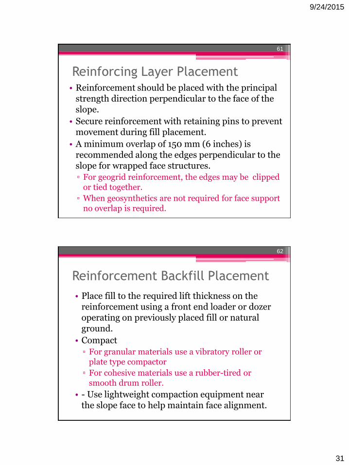
9/24/2015
31
Reinforcing Layer Placement• Reinforcement should be placed with the principal
strength direction perpendicular to the face of the slope.
• Secure reinforcement with retaining pins to prevent movement during fill placement.
• A minimum overlap of 150 mm (6 inches) is recommended along the edges perpendicular to the slope for wrapped face structures.
▫ For geogrid reinforcement, the edges may be clipped or tied together.
▫ When geosynthetics are not required for face support no overlap is required.
61
Reinforcement Backfill Placement
• Place fill to the required lift thickness on the reinforcement using a front end loader or dozer operating on previously placed fill or natural ground.
• Compact
▫ For granular materials use a vibratory roller or plate type compactor
▫ For cohesive materials use a rubber-tired or smooth drum roller.
• - Use lightweight compaction equipment near the slope face to help maintain face alignment.
62

9/24/2015
32
Compaction Control
• Provide close control on the water content and density of the backfill.
• If the backfill is a coarse aggregate▫ A relative density or a method type
compaction specification should be used.
63
Face Construction
• Slope facing requirements will depend on soil type, slope angle and the reinforcement spacing
• A face wrap may not be required for slopes up to 1H:1V.
▫ The reinforcement can be extended to the face.
• Slopes steeper than approximately 1:1 typically require facing support during construction.
64

9/24/2015
33
RSS slope facing options65
Treatment of outward face
• Grass Type Vegetation
• Soil Bioengineering (Woody Vegetation)
• Armored
66

9/24/2015
34
Grass Type Vegetation
• Erosion control and revegetation measures must be an integral part of all reinforced slope system designs and specifications.
• Reinforced slopes should be vegetated after construction to prevent or minimize erosion due to rainfall and runoff on the face.
• For the soil surface exposed, erosion control measures are necessary to prevent raveling and sloughing of the face.
67
Grass Type Vegetation
• A wrapped face helps reduce erosion problems▫ treatments are still required on the face to
shade geosynthetic soil reinforcement and prevent ultraviolet light exposure that will degrade the geosynthetic over time.
• A synthetic erosion control mat is normally used to improve the performance of grass cover.
68

9/24/2015
35
Grass Type Vegetation
• The erosion control mat serves to: ▫ protect the bare soil face against erosion until
the vegetation is established
▫ assist in reducing runoff velocity for increased water absorption by the soil
▫ reinforce the superficial root system of the vegetative cover.
69
Grass Type Vegetation
• Maintenance issues, must be carefully considered.
• The low erosion tolerance combined with other factors creates a need to evaluate revegetation measures as an integral part of the design.
• Guidance should be obtained from maintenance and regional landscaping groups to select the most appropriate low maintenance vegetation.
70

9/24/2015
36
Soil Bioengineering
(Woody Vegetation)
• Alternative to low growth, grass type vegetation
• Soil bioengineering uses living vegetation purposely arranged and imbedded in the ground to prevent shallow mass movement and superficial erosion.
▫ limited to stable slope masses.
▫ Combining it with geosynthetic reinforcement produces a durable and low maintenance structure.
• Woody vegetation improves the hydrology and mechanical stability of slopes through root reinforcement and surface protection.
71
Soil Bioengineering
(Woody Vegetation)
72

9/24/2015
37
Soil Bioengineering (Woody Vegetation)
73
Soil Bioengineering
(Woody Vegetation)• The use of deeply-installed and rooted woody
plant materials, purposely arranged and imbedded during slope construction offers:
▫ Immediate erosion control.
▫ Improved face stability.
▫ Reduced maintenance costs.
▫ Modification of soil moisture regimes.
▫ Enhanced wildlife habitat and ecological diversity.
▫ Improved aesthetic quality and naturalization.
74

9/24/2015
38
Soil Bioengineering
(Woody Vegetation)
• Plant science and horticulture are needed to select and establish the appropriate vegetation for:
▫ root reinforcement
▫ erosion control
▫ aesthetics
▫ the environment.
75
76

9/24/2015
39
Soil Bioengineering
(Woody Vegetation)• The vegetation used in the VRSS system is
typically in the form of:▫ live woody branch cuttings from species that
root adventitiously
▫ bare root and/or container plants.
77
Armored
• A permanent facing such as gunite or emulsified asphalt may be applied to provide long-term ultra-violet protection.
• Galvanized welded wire mesh reinforcement or gabions may also be used to facilitate face construction and provide permanent facing systems.
▫ Other armored facing elements may include riprap, stone veneer, articulating modular units, or fabric-formed concrete.
▫ Structural elements.
78

9/24/2015
40
Establish the geometric, loading, and
performance requirements for design
• Geometric and loading requirements▫ Slope height, H.
▫ Slope angle, θ.
▫ External (surcharge) loads Surcharge load, q
Temporary live load, ∆q
Design seismic acceleration, Am
▫ Traffic Barrier
79
Establish the geometric, loading, and
performance requirements for design
• Performance requirements.
▫ External stability and settlement.
Sliding: F.S. ≥ 1.3.
Deep seated (overall stability): F.S. ≥ 1.3.
Local bearing failure (lateral squeeze) : F.S. ≥ 1.3.
Dynamic loading: F.S. ≥ 1.1.
Settlement-post construction magnitude and time rate based on project requirements.
▫ Compound failure: F.S. ≥ 1.3.
▫ Internal slope stability: F.S. ≥ 1.3.
80

9/24/2015
41
Determine the engineering properties
of the in situ soils
• The foundation and retained soil profiles.
• Strength parameters for each soil layer
▫ cu and φu, or c´ and φ´
• Unit weights
▫ γwet and γdry
• Consolidation parameters
▫ Cc, Cr, cv and σ´p
• Location of the ground water table dw, and piezometric surfaces.
• For failure repair
▫ Identify location of previous failure surface and cause of failure.
81
Requirements for design of
reinforced soil slopes
82

9/24/2015
42
Determine the properties of reinforced
fill and, if different, the retained fill
• Gradation and plasticity index.
• Compaction characteristics based on 95% AASHTO T-99, γd and ±2% of optimum moisture, wopt.
• Compacted lift thickness.
• Shear strength parameters▫ cu, φu or c´, and φ´
• Chemical composition of soil (pH)
83
Evaluate design parameters for the
reinforcement• Allowable geosynthetic strength
▫ Significant cost advantage in obtaining lower RF from test data supplied by the manufacture and/or from agency evaluation.
• Allowable steel strength
• Pullout Resistance
▫ F.S. = 1.5 for granular soils.
▫ F.S. = 2 for cohesive soils.
▫ Minimum anchorage length, Le, = 1 m (3 ft)
84

9/24/2015
43
Check unreinforced stability
• Evaluate unreinforced stability to determine: ▫ If reinforcement is require
▫ critical nature of the design
▫ potential deep-seated failure problems
▫ extent of the reinforced zone.
▫ Use circular-arc and sliding-wedge methods to consider failure through
Toe, face (at several elevations), and deep-seated below the toe.
85
Check unreinforced stability
• Determine the size of the critical zone to be reinforced.▫ Examine full range of potential failure
surfaces:
Unreinforced safety factor (FSU) ≤ Required safety factor (FSR)
▫ Plot surfaces on the cross-section of the slope.
▫ The surfaces that just meet the required safety factor roughly envelope the limits of the critical zone to be reinforced.
86

9/24/2015
44
Critical zone defined by rotational
and sliding surfaces
87
Check unreinforced stability
• Critical failure surfaces extending below the toe of the slope are indications of deep foundation and edge bearing capacity. ▫ More extensive foundation analysis is
warranted.
▫ Foundation improvement measures should be considered.
88

9/24/2015
45
Design reinforcement to provide a
stable slope
• Calculate the total reinforcement tension per unit width of slope (TS) required to obtain the required factor of safety FSR for each potential failure surface inside the critical zone:
Where
89
Rotational shear approach to determine
required strength of reinforcement
90
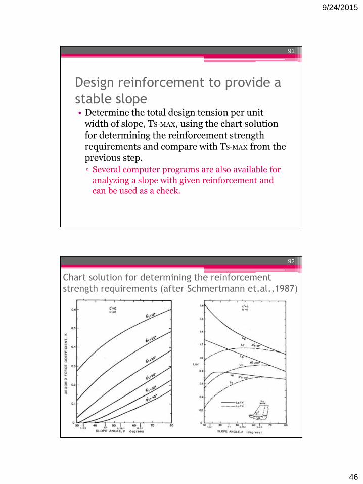
9/24/2015
46
Design reinforcement to provide a
stable slope• Determine the total design tension per unit
width of slope, TS-MAX, using the chart solution for determining the reinforcement strength requirements and compare with TS-MAX from the previous step.
▫ Several computer programs are also available for analyzing a slope with given reinforcement and can be used as a check.
91
Chart solution for determining the reinforcement
strength requirements (after Schmertmann et.al.,1987)
92

9/24/2015
47
Limiting Assumptions• Extensible reinforcement
• Slopes constructed with uniform, cohesionless soil, (c = 0)
• No pore pressures within the slope
• Competent, level foundation soils
• No seismic forces
• Uniform surcharge not greater than 0.2 γr H
• Relatively high soil/reinforcement interface friction angle, φsg = 0.9 φr
▫ may not be appropriate for some geosynthetics
93
Design reinforcement to provide a
stable slope
• Determine reinforcement vertical spacing Sv or the maximum design tension TMAX
requirements for each reinforcement layer.
▫ For each zone, calculate TMAX :
• Where
94

9/24/2015
48
Design reinforcement to provide a
stable slope• Use short 4 to 6.5 ft (1.2 to 2 m) lengths of
intermediate reinforcement layers to maintain a maximum vertical spacing of 16 in.
• To ensure that the rule-of-thumb reinforcement force distribution is adequate for critical or complex structures
▫ recalculate TS using equation
to determine potential failure above each layer of primary reinforcement
95
Design reinforcement to provide a
stable slope• Determine the reinforcement lengths required:
▫ Minimum value of Le is 3 ft (1 m).
▫ For long-term design
Φ’r and c’r = 0
▫ For short-term evaluation
φr with cr = 0 from consolidated undrained triaxialor direct shear tests or run pullout tests
96

9/24/2015
49
Design reinforcement to provide a
stable slope• Plot the reinforcement lengths as obtained from the
pullout evaluation on a slope cross section containing the rough limits of the critical zone determined in the check unreinforced stability step.
▫ The length required for sliding stability at the base will generally control the length of the lower reinforcement levels.
▫ Lower layer lengths must extend at least to the limits of the critical zone. Longer reinforcements may be required to resolve deep seated failure problems.
▫ Upper levels of reinforcement may not be required to extend to the limits of the critical zone.
97
Design reinforcement to provide a
stable slope• Check that the sum of the reinforcement forces
passing through each failure surface is greater than Ts required for that surface.
▫ If the available reinforcement force is not sufficient
increase the length of reinforcement not passing through the surface or increase the strength of lower level reinforcement.
98

9/24/2015
50
Developing reinforcement lengths
99
Check external stability
• Sliding resistance
▫ Evaluate the width of the reinforced soil zone at any level to resist sliding along the reinforcement.
▫ The analysis can best be performed using a computerized method which takes into account all soil strata and interface friction values.
▫ The frictional resistance provided by the weakest layer should be used in the analysis.
100

9/24/2015
51
Check external stability
• Deep seated global stability
▫ Evaluate potential deep-seated failure surfaces behind the reinforced soil zone:
F.S. ≥ 1.3 is recommended as a minimum and that value should be increased based on the criticality of the slope
101
Deep seated (global) stability
analysis
102

9/24/2015
52
Check external stability• Local bearing failure
at the toe
▫ If a weak soil layer exists beneath the embankment to a limited depth DS, the factor of safety against failure by squeezing may be calculated from:
• Where
103
Check external stability
• Foundation settlement.
▫ Determine the magnitude and rate of total and differential foundation settlements using classical geotechnical engineering procedures
104

9/24/2015
53
Seismic stability
• Dynamic stability
▫ Perform a pseudo-static type analysis using a seismic ground coefficient A, obtained from local building code and a design seismic acceleration Am equal to Am = A/2.
105
Seismic stability analysis
106

9/24/2015
54
Evaluate requirements for subsurface
and surface water runoff control
• Subsurface water control.
▫ Design should address
flow rate, filtration, placement, and outlet details
▫ Drains are typically placed at the rear of the reinforced zone.
Geocomposite drainage systems or conventional granular blanket and trench drains could be used (see Chapter 5).
107
Ground water and surface drainage
108

9/24/2015
55
Typical drain details
109
Evaluate requirements for subsurface
and surface water runoff control
• Geosynthetic drainage composites can be used in subsurface water drainage design.
• Should be designed with consideration of:
▫ Geotextile filtration/clogging
▫ Long-term compressive strength of polymeric core
▫ Reduction of flow capacity due to intrusion of geotextile into the core
▫ Long-term inflow/outflow capacity
110

9/24/2015
56
Questions?
111
References
• http://www.tencate.com/pt/lam/Images/bro_mse0208_tcm31-10770.pdf
• Elias, V., Christopher, B., Berg, R. (2001). Mechanically Stabilized Earth Walls and Reinforced Soil Slopes Design and Construction Guidelines. FHWA-NHI-00-043. Washington, D.C. :National Highway Institute.
112