Centripetal Force Lab Edited 1.9 · 2020-01-10 · 3 Just like the centripetal acceleration, the...
10
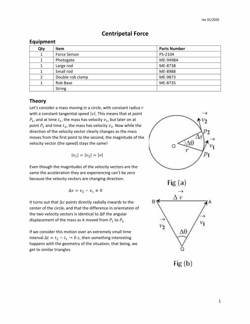
1 Centripetal Force Equipment Qty Item Parts Number 1 Force Sensor PS‐2104 1 Photogate ME‐9498A 1 Large rod ME‐8738 1 Small rod ME‐8988 2 Double rob clamp ME‐9873 1 Rob Base ME‐8735 String Theory Let’s consider a mass moving in a circle, with constant radius with a constant tangential speed ||. This means that at point ଵ , and at time ଵ , the mass has velocity ଵ , but later on at point ଵ and time ଶ , the mass has velocity ଶ . Now while the direction of the velocity vector clearly changes as the mass moves from the first point to the second, the magnitude of the velocity vector (the speed) stays the same! | ଵ | ൌ | ଶ | ൌ || Even though the magnitudes of the velocity vectors are the same the acceleration they are experiencing can’t be zero because the velocity vectors are changing direction. ∆ ൌ ଶ െ ଵ 0 It turns out that ∆ points directly radially inwards to the center of the circle, and that the difference in orientation of the two velocity vectors is identical to ∆ the angular displacement of the mass as it moved from ଵ to ଶ. If we consider this motion over an extremely small time interval ∆ ൌ ଶ െ ଵ → 0 , then something interesting happens with the geometry of the situation; that being, we get to similar triangles. rev 01/2020
Transcript of Centripetal Force Lab Edited 1.9 · 2020-01-10 · 3 Just like the centripetal acceleration, the...
1
Centripetal Force Equipment
Qty Item Parts Number
1 Force Sensor PS‐2104
1 Photogate ME‐9498A
1 Large rod ME‐8738
1 Small rod ME‐8988
2 Double rob clamp ME‐9873
1 Rob Base ME‐8735
String
TheoryLet’s consider a mass moving in a circle, with constant radius 𝑟 with a constant tangential speed |𝑣|. This means that at point
𝑃 , and at time 𝑡 , the mass has velocity 𝑣 , but later on at point 𝑃 and time 𝑡 , the mass has velocity 𝑣 . Now while the direction of the velocity vector clearly changes as the mass
moves from the first point to the second, the magnitude of the
velocity vector (the speed) stays the same!
|𝑣 | |𝑣 | |𝑣|
Even though the magnitudes of the velocity vectors are the
same the acceleration they are experiencing can’t be zero
because the velocity vectors are changing direction.
∆𝑣 𝑣 𝑣 0
It turns out that ∆𝑣 points directly radially inwards to the center of the circle, and that the difference in orientation of
the two velocity vectors is identical to ∆𝜃 the angular displacement of the mass as it moved from 𝑃 to 𝑃 .
If we consider this motion over an extremely small time
interval ∆𝑡 𝑡 𝑡 → 0 𝑠, then something interesting
happens with the geometry of the situation; that being, we
get to similar triangles.
rev 01/2020
2
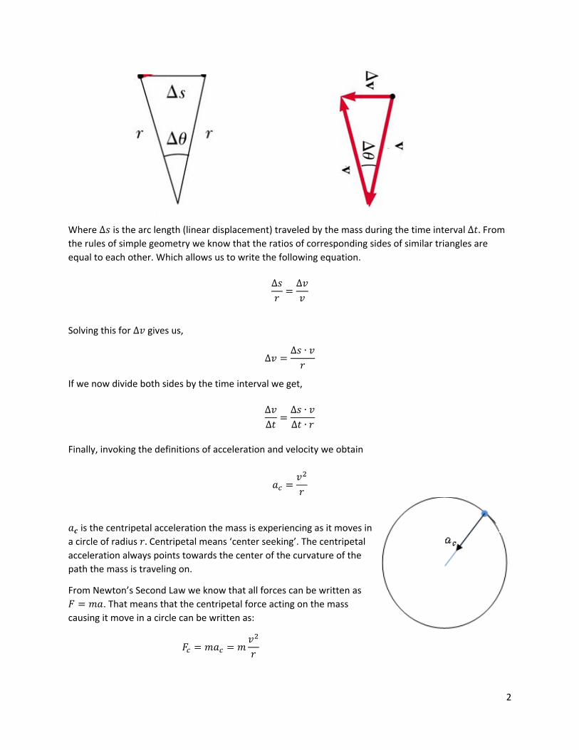
Where ∆𝑠 is the arc length (linear displacement) traveled by the mass during the time interval ∆𝑡. From
the rules of simple geometry we know that the ratios of corresponding sides of similar triangles are
equal to each other. Which allows us to write the following equation.
∆𝑠𝑟
∆𝑣𝑣
Solving this for ∆𝑣 gives us,
∆𝑣∆𝑠 ∙ 𝑣
𝑟
If we now divide both sides by the time interval we get,
∆𝑣∆𝑡
∆𝑠 ∙ 𝑣∆𝑡 ∙ 𝑟
Finally, invoking the definitions of acceleration and velocity we obtain
𝑎𝑣𝑟
𝑎𝒄 is the centripetal acceleration the mass is experiencing as it moves in
a circle of radius 𝑟. Centripetal means ‘center seeking’. The centripetal
acceleration always points towards the center of the curvature of the
path the mass is traveling on.
From Newton’s Second Law we know that all forces can be written as
𝐹 𝑚𝑎. That means that the centripetal force acting on the mass
causing it move in a circle can be written as:
𝐹 𝑚𝑎 𝑚𝑣𝑟
3
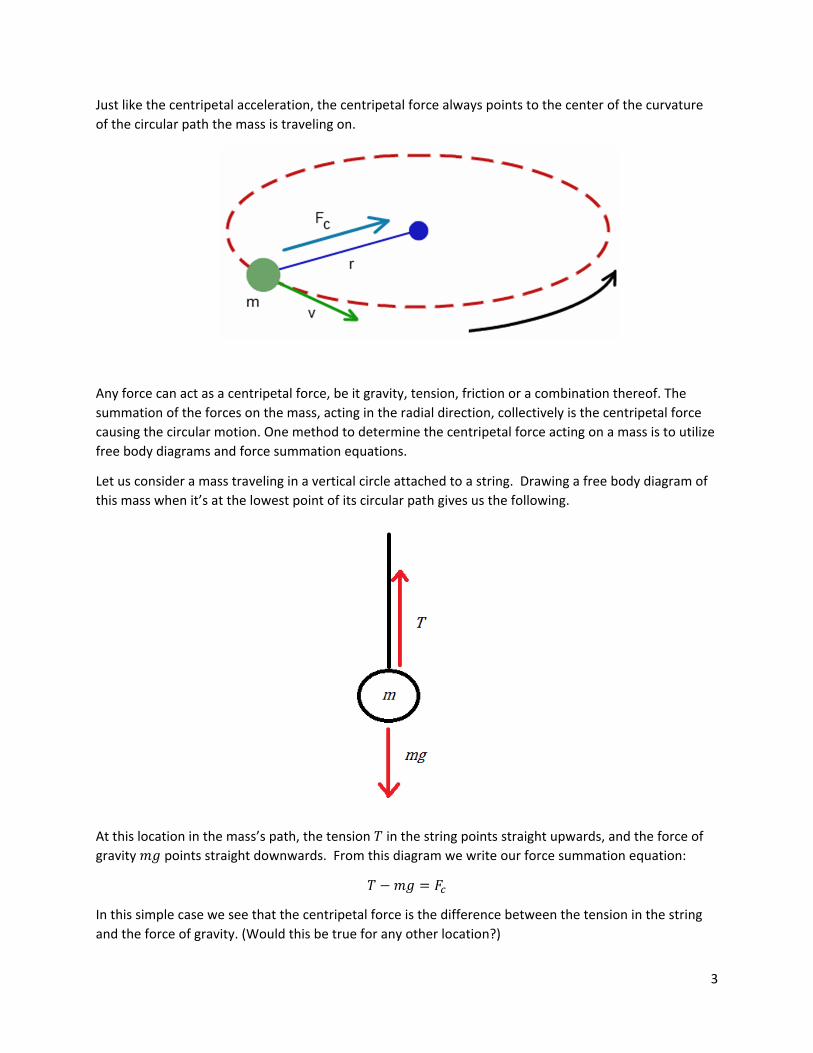
Just like the centripetal acceleration, the centripetal force always points to the center of the curvature
of the circular path the mass is traveling on.
Any force can act as a centripetal force, be it gravity, tension, friction or a combination thereof. The
summation of the forces on the mass, acting in the radial direction, collectively is the centripetal force
causing the circular motion. One method to determine the centripetal force acting on a mass is to utilize
free body diagrams and force summation equations.
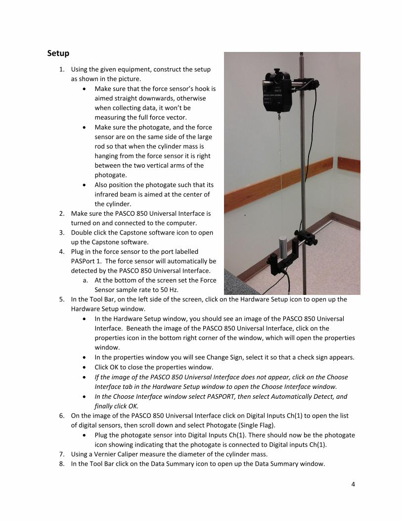
Let us consider a mass traveling in a vertical circle attached to a string. Drawing a free body diagram of
this mass when it’s at the lowest point of its circular path gives us the following.
At this location in the mass’s path, the tension 𝑇 in the string points straight upwards, and the force of gravity 𝑚𝑔 points straight downwards. From this diagram we write our force summation equation:
𝑇 𝑚𝑔 𝐹
In this simple case we see that the centripetal force is the difference between the tension in the string
and the force of gravity. (Would this be true for any other location?)
4
Setup
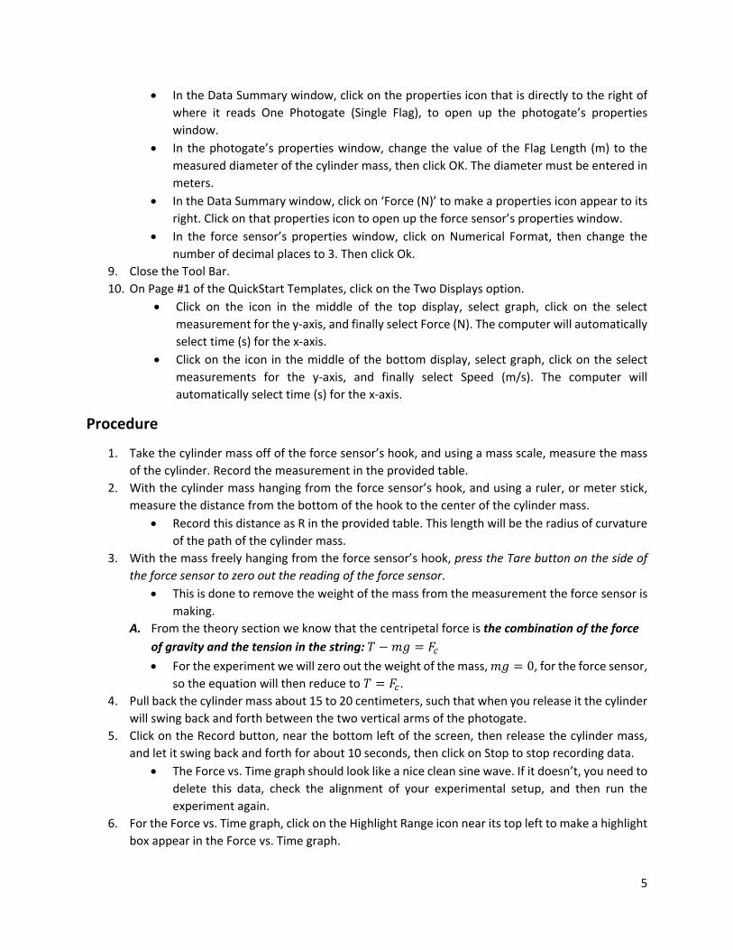
1. Using the given equipment, construct the setup
as shown in the picture.
Make sure that the force sensor’s hook is
aimed straight downwards, otherwise
when collecting data, it won’t be
measuring the full force vector.
Make sure the photogate, and the force
sensor are on the same side of the large
rod so that when the cylinder mass is
hanging from the force sensor it is right
between the two vertical arms of the
photogate.
Also position the photogate such that its
infrared beam is aimed at the center of
the cylinder.
2. Make sure the PASCO 850 Universal Interface is
turned on and connected to the computer.
3. Double click the Capstone software icon to open
up the Capstone software.
4. Plug in the force sensor to the port labelled
PASPort 1. The force sensor will automatically be
detected by the PASCO 850 Universal Interface.
a. At the bottom of the screen set the Force
Sensor sample rate to 50 Hz.
5. In the Tool Bar, on the left side of the screen, click on the Hardware Setup icon to open up the
Hardware Setup window.
In the Hardware Setup window, you should see an image of the PASCO 850 Universal
Interface. Beneath the image of the PASCO 850 Universal Interface, click on the
properties icon in the bottom right corner of the window, which will open the properties
window.
In the properties window you will see Change Sign, select it so that a check sign appears.
Click OK to close the properties window.
If the image of the PASCO 850 Universal Interface does not appear, click on the Choose
Interface tab in the Hardware Setup window to open the Choose Interface window.
In the Choose Interface window select PASPORT, then select Automatically Detect, and
finally click OK.
6. On the image of the PASCO 850 Universal Interface click on Digital Inputs Ch(1) to open the list
of digital sensors, then scroll down and select Photogate (Single Flag).
Plug the photogate sensor into Digital Inputs Ch(1). There should now be the photogate
icon showing indicating that the photogate is connected to Digital inputs Ch(1).
7. Using a Vernier Caliper measure the diameter of the cylinder mass.
8. In the Tool Bar click on the Data Summary icon to open up the Data Summary window.
5
In the Data Summary window, click on the properties icon that is directly to the right of
where it reads One Photogate (Single Flag), to open up the photogate’s properties
window.
In the photogate’s properties window, change the value of the Flag Length (m) to the
measured diameter of the cylinder mass, then click OK. The diameter must be entered in
meters.
In the Data Summary window, click on ‘Force (N)’ to make a properties icon appear to its
right. Click on that properties icon to open up the force sensor’s properties window.
In the force sensor’s properties window, click on Numerical Format, then change the
number of decimal places to 3. Then click Ok.
9. Close the Tool Bar.
10. On Page #1 of the QuickStart Templates, click on the Two Displays option.
Click on the icon in the middle of the top display, select graph, click on the select
measurement for the y‐axis, and finally select Force (N). The computer will automatically
select time (s) for the x‐axis.
Click on the icon in the middle of the bottom display, select graph, click on the select
measurements for the y‐axis, and finally select Speed (m/s). The computer will
automatically select time (s) for the x‐axis.
Procedure
1. Take the cylinder mass off of the force sensor’s hook, and using a mass scale, measure the mass
of the cylinder. Record the measurement in the provided table.
2. With the cylinder mass hanging from the force sensor’s hook, and using a ruler, or meter stick,
measure the distance from the bottom of the hook to the center of the cylinder mass.
Record this distance as R in the provided table. This length will be the radius of curvature
of the path of the cylinder mass.
3. With the mass freely hanging from the force sensor’s hook, press the Tare button on the side of
the force sensor to zero out the reading of the force sensor.
This is done to remove the weight of the mass from the measurement the force sensor is
making.
A. From the theory section we know that the centripetal force is the combination of the force
of gravity and the tension in the string: 𝑇 𝑚𝑔 𝐹
For the experiment we will zero out the weight of the mass, 𝑚𝑔 0, for the force sensor, so the equation will then reduce to 𝑇 𝐹 .
4. Pull back the cylinder mass about 15 to 20 centimeters, such that when you release it the cylinder
will swing back and forth between the two vertical arms of the photogate.
5. Click on the Record button, near the bottom left of the screen, then release the cylinder mass,
and let it swing back and forth for about 10 seconds, then click on Stop to stop recording data.
The Force vs. Time graph should look like a nice clean sine wave. If it doesn’t, you need to
delete this data, check the alignment of your experimental setup, and then run the
experiment again.
6. For the Force vs. Time graph, click on the Highlight Range icon near its top left to make a highlight
box appear in the Force vs. Time graph.
6
Rescale the highlight box. Move and adjust it until it covers one complete wave cycle.
7. Near the top left of the Force vs. Time graph, click on the down arrow next to the capital sigma to
open up the highlighted data list.
Select maximum, and minimum, make sure nothing else is selected, then click on the
capital sigma itself to make the selected values appear on the Force vs. Time graph.
Record those two values in the provided table.
8. Near the top right of the Speed vs. Time graph, click on the Add a Coordinate Tool icon to add a
coordinate tool to the Speed vs. Time graph.
Use the coordinate tool to find the value of the speed of the mass that corresponds to
the same time interval as the wave cycle that you highlighted in the Force vs. Time graph,
and record that value in the table provided.
9. Repeat procedure steps 1 – 8 for the second cylinder mass.
7
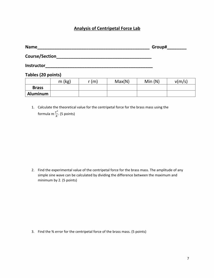
Analysis of Centripetal Force Lab
Name______________________________________________ Group#________
Course/Section_______________________________________
Instructor____________________________________________
Tables (20 points)
m (kg) r (m) Max(N) Min (N) v(m/s)
Brass
Aluminum
1. Calculate the theoretical value for the centripetal force for the brass mass using the
formula 𝑚 . (5 points)
2. Find the experimental value of the centripetal force for the brass mass. The amplitude of any
simple sine wave can be calculated by dividing the difference between the maximum and
minimum by 2. (5 points)
3. Find the % error for the centripetal force of the brass mass. (5 points)
8
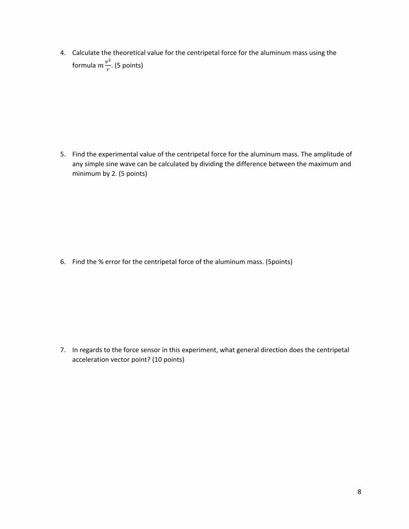
4. Calculate the theoretical value for the centripetal force for the aluminum mass using the
formula 𝑚 . (5 points)
5. Find the experimental value of the centripetal force for the aluminum mass. The amplitude of
any simple sine wave can be calculated by dividing the difference between the maximum and
minimum by 2. (5 points)
6. Find the % error for the centripetal force of the aluminum mass. (5points)
7. In regards to the force sensor in this experiment, what general direction does the centripetal
acceleration vector point? (10 points)
9
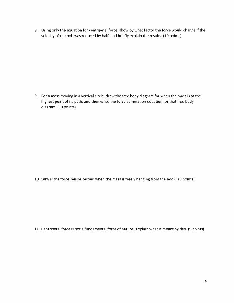
8. Using only the equation for centripetal force, show by what factor the force would change if the
velocity of the bob was reduced by half, and briefly explain the results. (10 points)
9. For a mass moving in a vertical circle, draw the free body diagram for when the mass is at the
highest point of its path, and then write the force summation equation for that free body
diagram. (10 points)
10. Why is the force sensor zeroed when the mass is freely hanging from the hook? (5 points)
11. Centripetal force is not a fundamental force of nature. Explain what is meant by this. (5 points)
10
12. Do the results of the experiment confirm the theory? Explain your answer. (5 points)
13. What are possible reasons for the differences between the experimental and theoretical values
of centripetal force? (5 points)