Centrifugal Water Chillersfile.upi.edu/Direktori/FPTK/JUR._PEND._TEKNIK_MESIN/...Centrifugal Water...
46
Air Conditioning Clinic TRG-TRC010-EN © American Standard Inc. 1999 Centrifugal Water Chillers period three Refrigeration Cycle Lubrication System
Transcript of Centrifugal Water Chillersfile.upi.edu/Direktori/FPTK/JUR._PEND._TEKNIK_MESIN/...Centrifugal Water...

Air Conditioning Clinic TRG-TRC010-EN© American Standard Inc. 1999
Centrifugal Water
Chillers
period three
Refrigeration Cycle
Lubrication System

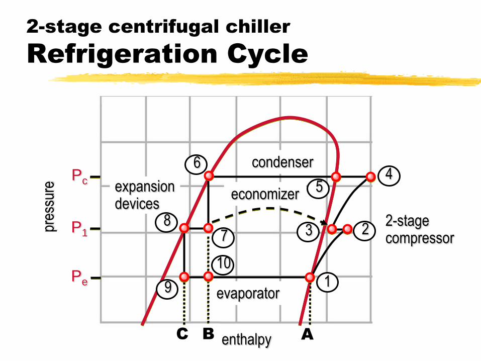
2-stage centrifugal chiller
Refrigeration Cycle
condenserevaporator
expansion devices
economizer
2-stagecompressor


Pressure-Enthalpy (p-h)
Chart
enthalpy
subcooledliquid
mixture of liquid and vapor
15.5 Btu/lb[201.0 kJ/kg]
pres
sure
superheatedvapor
BA5 psia
[0.034 MPa]
92.4 Btu/lb[380.4 kJ/kg]

2-stage centrifugal chiller
Refrigeration Cycle
1
23
46
7
pres
sure
enthalpy
evaporator
condenser
2-stage compressor
expansion devices
8
9Pe
Pc
P1
5economizer
2-stage centrifugal chiller
Refrigeration Cycle
enthalpy
pres
sure
Pe
Pc
P1
C B A
2-stage compressor
4
1
2
evaporator
condenser6
7
9
5economizer
3
expansion devices
10
8

Motor Cooling & Lubrication
System
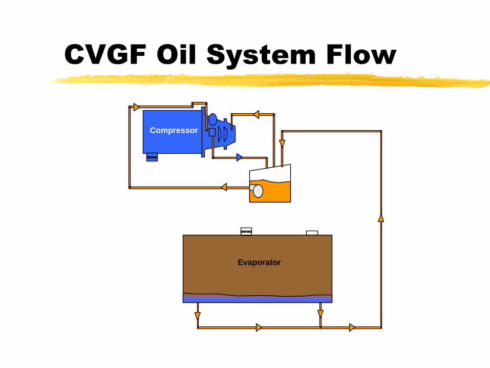
CVGF Oil System Flow
Evaporator
Compressor

CVGF Oil Cooling System
Brazed Plate H/E
Liquid
Refrigerant
Sat Liquid + Vapor
Refrigerant Compressor
Thermosiphon
Action

CVGF Oil Return System
99% refrigerant
+ 1% Oil
Refrigerant
vapor
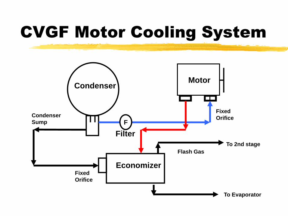
CVGF Motor Cooling System
CondenserMotor
Economizer
F
Filter
Fixed
Orifice
Condenser
Sump
Fixed
Orifice
Flash Gas
To Evaporator
To 2nd stage

Hermetic Motor Cooling
stator
rotor
Drain
(to Economizer)Liquid refrigerant
(from Condenser Sump)

Air Conditioning Clinic TRG-TRC010-EN© American Standard Inc. 1999
Centrifugal Water
Chillers
period four
Compressor Capacity Control

Multistage Compressor
inlet vanes
impellers
VrR
Vt
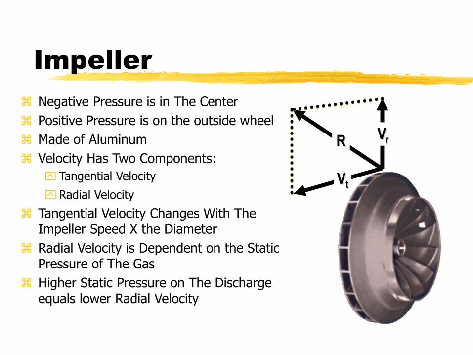
Impeller
Negative Pressure is in The Center
Positive Pressure is on the outside wheel
Made of Aluminum
Velocity Has Two Components:
Tangential Velocity
Radial Velocity
Tangential Velocity Changes With The Impeller Speed X the Diameter
Radial Velocity is Dependent on the Static Pressure of The Gas
Higher Static Pressure on The Discharge equals lower Radial Velocity

Impeller Dynamics
Vr refrigerant flow rate
Vt rotational speed × diameter
diameter
rotational
speed
VrR
Vt
refrigerant flow rate
Output is Equal to the Diameter, Speed and Volume of the Impeller.
Change the Static Pressure, Output Changes
Static Pressure Can Rise Due To:
Water Flow
Dirty Coils
High Differential Compressor Pressures
High Discharge Pressures

Compressor Unloading
VrR
Vt
Vr
Vt
full
load
part
load
R

Surge
Vr < static pressure
Vr
Vt
R
High Condenser Water Temperature Causes Surge
Low Load Conditions Causes Surge
Surge Causes:
Inefficiency
Static Pressure Fluctuations
Vibration
Noise

Inlet Vanes
inlet vanes impeller
Impeller Volume Changes Are Controlled By Inlet Vanes
Inlet Vanes Pre-spin The Entering Gas
Inlet Vanes are Electronically Controlled By a Stepper Motor
System Design Curves Tell The Story

Compressor Map
refrigerant flow rate
25
75
10 14
63
pres
sure
diff
eren
ce
vane position(degrees)
90
36
51

Operating Point
pres
sure
diff
eren
ce
refrigerant flow rate
operatingpoint
Operating Point at Design Conditions
Specific Unit Tonnage or kW
Specific Wheel Design
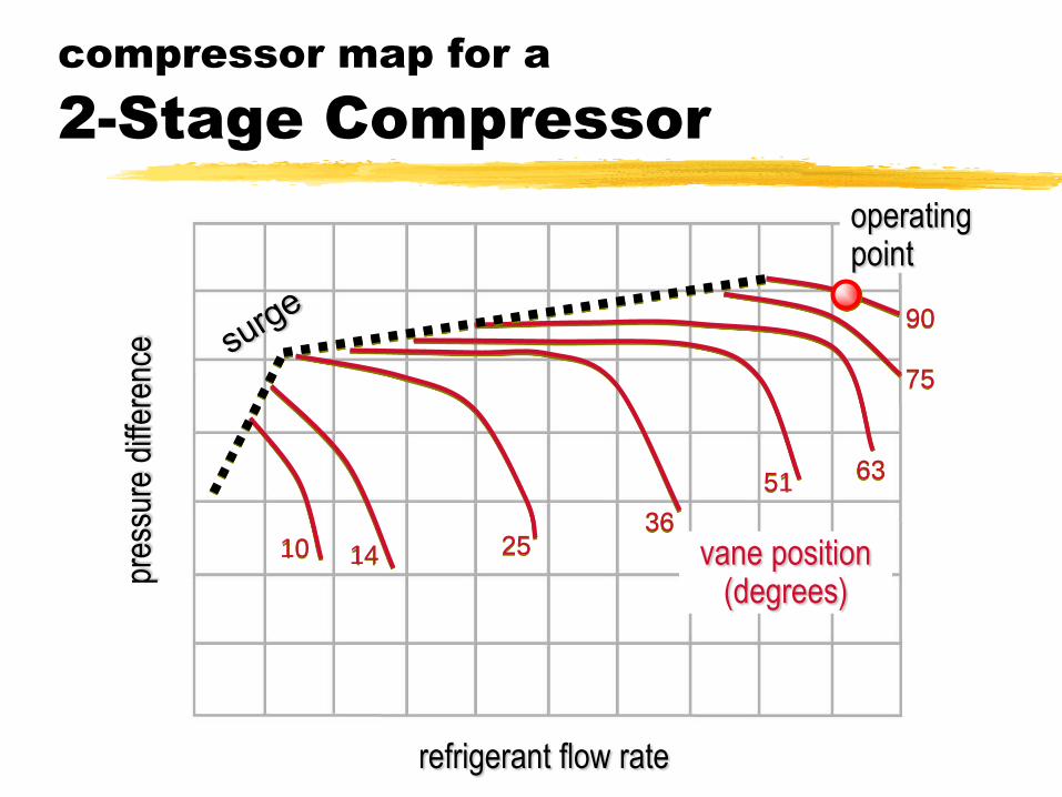
compressor map for a
2-Stage Compressor
25
75
10 14
63
pres
sure
diff
eren
ce
refrigerant flow rate
90
36
51
operatingpoint
vane position(degrees)

compressor map for a
2-Stage Compressor
25
75
10 14
63
pres
sure
diff
eren
ce
refrigerant flow rate
90
36
51
CB
A
unloading line

Operating Point Unloader Changes
As Vanes Close, CFM - m3/s Changes
CVGF Impeller Curve
Load Charts
Del
ta P
90°60°40°20°
2
15o

Air Conditioning Clinic TRG-TRC010-EN© American Standard Inc. 1999
Centrifugal Water
Chillers
period five
Features and Benefits

CVGF Features and Benefits
Performance
Competitive Performance
High efficiency (0.59 Kw/Ton @ARI)
Standard efficiency (0.64 Kw/Ton @ARI)
With two stage compressor and inter stage economizer
Economizer cycle adds 3% improvement on efficiency
Advanced heat transfer technology
Advanced evaporator design reduces the refrigerant charge (1.3 ~ 1.5 lbs Refrigerant per ton)
No eliminator necessary with an advanced suction baffle design
Low noise

CVGF Features and Benefits
REFRIGERANT CHARGE
Refrigerant Charge - 134a
Evaporator Single
Size Bundle Condenser
LBS KG
500 A 650 295
B 701 318 Constant for LBS. Conversion
C 750 340 2.20462
700 A 875 397
B 924 419
C 974 442
1000 A 1225 556
B 1275 578
C 1325 601
D 1375 624

CVGF Features and Benefits
MODEL CVGF 400 – 500
Sound Level
Sound pressure level (at 1 meter) at full load, 50 % and 25 % part load conditions:
CVGF 400 – 500 NTON 100 % load 50 % load 25 % load
Asia Conditions **
Without condenser relief
82 dBA 85 dBA 86 dBA
Sound Pressure Levels (anticipated) – dB re 20 micropascal
Octave
Band
Constant Condenser Water
100 % load 50% load 25% load
63 Hz 67 73 75.5
125 Hz 70 84.5 82
250 Hz 69 74 75.5
500 Hz 70.5 72 76
1000 Hz 79 78 81.5
2000 Hz 74.5 81.5 81
4000 Hz 71 74.5 76
8000 Hz 60.5 62.5 70
* ARI Standard 550 / 590 rating conditions.
** Asia conditions LEWT = 44.6 F / ECWT = 89.6 F.
Test conducted in accordance with ARI Standard 575.
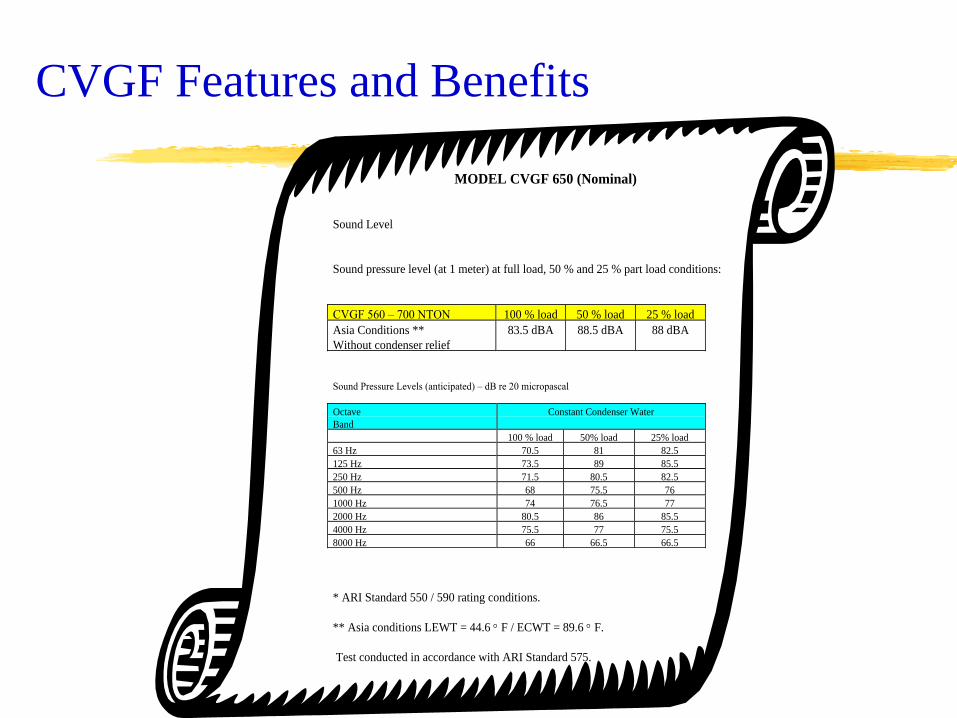
CVGF Features and Benefits
MODEL CVGF 650 (Nominal)
Sound Level
Sound pressure level (at 1 meter) at full load, 50 % and 25 % part load conditions:
CVGF 560 – 700 NTON 100 % load 50 % load 25 % load
Asia Conditions **
Without condenser relief
83.5 dBA 88.5 dBA 88 dBA
Sound Pressure Levels (anticipated) – dB re 20 micropascal
Octave
Band
Constant Condenser Water
100 % load 50% load 25% load
63 Hz 70.5 81 82.5
125 Hz 73.5 89 85.5
250 Hz 71.5 80.5 82.5
500 Hz 68 75.5 76
1000 Hz 74 76.5 77
2000 Hz 80.5 86 85.5
4000 Hz 75.5 77 75.5
8000 Hz 66 66.5 66.5
* ARI Standard 550 / 590 rating conditions.
** Asia conditions LEWT = 44.6 F / ECWT = 89.6 F.
Test conducted in accordance with ARI Standard 575.

CVGF Features and Benefits
MODEL CVGF 800 -1000
Sound Level
Sound pressure level (at 1 meter) at full load, 50 % and 25 % part load conditions:
CVGF 800 – 1000 NTON 100 % load 50 % load 25 % load
Without condenser relief ** 81 dBA 79.5 dBA 88 dBA
Sound Pressure Levels (anticipated) – dB re 20 micropascal
Octave
Band
Constant Condenser Water
100 % load 50% load 25% load
63 Hz 66.5 70 67.5
125 Hz 74 76 81
250 Hz 73 73.5 79
500 Hz 70.5 70.5 72
1000 Hz 72 71.5 75.5
2000 Hz 77.5 76 86.5
4000 Hz 73 69 72.5
8000 Hz 63 61 67
** Rating conditions LEWT = 44 F / ECWT = 85 F.
Test conducted in accordance with ARI Standard 575

CVGF Features and Benefits
Reliability
With hermetic motor design, motor is cooled by liquid refrigerant. Better motor efficient
Patented integral heater imbedded into the compressor casting, no seals, no leaks
Beaded flat gasket technology instead of O-rings, lower susceptibility to developing leaks
No NPT pipe threads on compressor, SAE O-ring boss fitting, lower leak potential
Oil sump internal to Compressor / motor assembly with internal pump / motor, eliminates vent & drain lines, less leak paths.

CVGF Features and Benefits
Reliability
UL / CUL recognized
CE / PED
ASME shell design
Patented polygon attachment instead of a keyed shaft, self balancing
Heaters, oil filter, oil differential pressure switch and temp sensors are all replaceable w/o removing system charge

Reliability
UCP-2 Intelligent Control
Provides over 120 Diagnostics and Operating Points
Standard Report Groupings
User Tailored Custom Reports
Levels of Security
CVGF Features and Benefits

Reliability
Integrated Comfort System Trane Tracer Summit Control
Chiller Plant Manager Control
ICS -- UCP-2 Chiller Control System
BACNet Compatible and Modbus Compatible
CVGF Features and Benefits

Low maintenance
Zero maintenance motor, liquid cooled
No shaft seal will make sure no risk of refrigerant loss through shaft
No shaft alignment problem
No couplings
No purge
CVGF Features and Benefits

Ease of installation Compact size
CVGF500 fits through a double-width door
Excellent choice for retrofit and replacement jobs due to compact size
No oil cooler or purge system connections
Unit mounted starter eliminates additional jobsite labor requirements
Factory wired UCP2 and united mounted starter
CVGF Features and Benefits

Optional Features
Special tubing material (CuNi, Titanium)
Special thickness
Titanium clatted tubesheet
Heresite coated waterbox
IQD (digital ammeter and digital voltmeter)
PFCC (power factor correction capacitor)
NEMA 4A for control panel; NEMA 12/3R for starter
150# / 300# MAR waterboxes for evap or cond
Factory-applied thermal insulation
Spring Isolators
BAS Interface
Factory testing
CVGF Features and Benefits

Low Medium High Low Medium
240 298 221 276
266 332 254 318
301 376 285 358
338 424 316 398
374 470 357 452
430 541 401 509
484 609 444 564
535 675 511 650
594 750 574 731
674 854 641 810
751 950 719 910
808 1025
Available NOW Available NOW
Available NOW Available 5/9/01
50 Hz 60 Hz
Volt RangeKW HP
Volt RangeKW HP
5000
Frame 5000
Frame
440E
Frame440E
Frame
400 &
440E
Frame
400 &
440E
Frame
5000
Frame
5000
Frame
CVGF Features and Benefits
Optional Features Medium / High Voltage (60Hz : 3300, 4160, 6600V)
(50Hz : 3300, 6600V)

Air Conditioning Clinic TRG-TRC010-EN© American Standard Inc. 1999
Centrifugal Water
Chillers
period six
Competitions
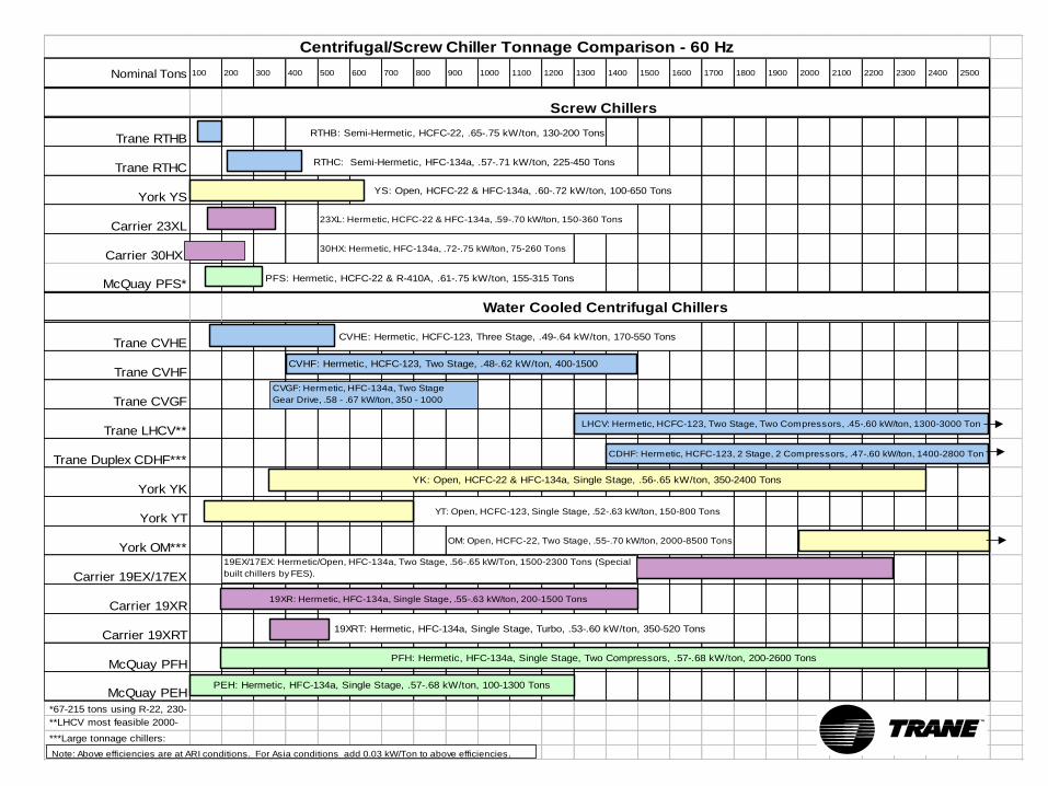
Centrifugal/Screw Chiller Tonnage Comparison - 60 Hz
Nominal Tons 100 200 300 400 500 600 700 800 900 1000 1100 1200 1300 1400 1500 1600 1700 1800 1900 2000 2100 2200 2300 2400 2500
Screw Chillers
Trane RTHB RTHB: Semi-Hermetic, HCFC-22, .65-.75 kW/ton, 130-200 Tons
Trane RTHC RTHC: Semi-Hermetic, HFC-134a, .57-.71 kW/ton, 225-450 Tons
York YS YS: Open, HCFC-22 & HFC-134a, .60-.72 kW/ton, 100-650 Tons
Carrier 23XL 23XL: Hermetic, HCFC-22 & HFC-134a, .59-.70 kW/ton, 150-360 Tons
Carrier 30HX 30HX: Hermetic, HFC-134a, .72-.75 kW/ton, 75-260 Tons
McQuay PFS* PFS: Hermetic, HCFC-22 & R-410A, .61-.75 kW/ton, 155-315 Tons
Water Cooled Centrifugal Chillers
Trane CVHE CVHE: Hermetic, HCFC-123, Three Stage, .49-.64 kW/ton, 170-550 Tons
Trane CVHF
Trane CVGF
Trane LHCV**
Trane Duplex CDHF***
York YK
York YT YT: Open, HCFC-123, Single Stage, .52-.63 kW/ton, 150-800 Tons
York OM*** OM: Open, HCFC-22, Two Stage, .55-.70 kW/ton, 2000-8500 Tons
Carrier 19EX/17EX
Carrier 19XR
Carrier 19XRT 19XRT: Hermetic, HFC-134a, Single Stage, Turbo, .53-.60 kW/ton, 350-520 Tons
McQuay PFH
McQuay PEH
*67-215 tons using R-22, 230-
310 tons using R410A. **LHCV most feasible 2000-
3000 tons. Theoretically ***Large tonnage chillers:
York OM 2000-8500 tons with
CVHF: Hermetic, HCFC-123, Two Stage, .48-.62 kW/ton, 400-1500
LHCV: Hermetic, HCFC-123, Two Stage, Two Compressors, .45-.60 kW/ton, 1300-3000 Ton
YK: Open, HCFC-22 & HFC-134a, Single Stage, .56-.65 kW/ton, 350-2400 Tons
PEH: Hermetic, HFC-134a, Single Stage, .57-.68 kW/ton, 100-1300 Tons
PFH: Hermetic, HFC-134a, Single Stage, Two Compressors, .57-.68 kW/ton, 200-2600 Tons
19XR: Hermetic, HFC-134a, Single Stage, .55-.63 kW/ton, 200-1500 Tons
CDHF: Hermetic, HCFC-123, 2 Stage, 2 Compressors, .47-.60 kW/ton, 1400-2800 Ton
CVGF: Hermetic, HFC-134a, Two Stage
Gear Drive, .58 - .67 kW/ton, 350 - 1000
19EX/17EX: Hermetic/Open, HFC-134a, Two Stage, .56-.65 kW/Ton, 1500-2300 Tons (Special
built chillers by FES).
Note: Above efficiencies are at ARI conditions. For Asia conditions add 0.03 kW/Ton to above efficiencies.

Centrifugal/Screw Chiller Tonnage Comparison - 50 Hz
Nominal Tons 100 200 300 400 500 600 700 800 900 1000 1100 1200 1300 1400 1500 1600 1700 1800 1900 2000 2100 2200 2300 2400 2500
Screw Chillers
Trane RTHB RTHB: Semi-Hermetic, HCFC-22, .65-.75 kW/ton, 130-200 Tons
Trane RTHC RTHC: Semi-Hermetic, HFC-134a, .57-.71 kW/ton, 225-450 Tons
York YS YS: Open, HCFC-22 & HFC-134a, .60-.72 kW/ton, 100-650 Tons
Carrier 23XL 23XL: Hermetic, HCFC-22 & HFC-134a, .59-.70 kW/ton, 150-360 Tons
Carrier 30HX 30HX: Hermetic, HFC-134a, .72-.75 kW/ton, 75-260 Tons
McQuay PFS* PFS: Hermetic, HCFC-22 & R-410A, .61-.75 kW/ton, 155-315 Tons
Water Cooled Centrifugal Chillers
Trane CVHE CVHE: Hermetic, HCFC-123, Three Stage, .49-.64 kW/ton, 170-500 Tons
Trane CVHG
Trane CVGF
Trane LHCV**
Trane Duplex CDHF***
York YK
York YT YT: Open, HCFC-123, Single Stage, .52-.63 kW/ton, 150-800 Tons
York OM*** OM: Open, HCFC-22, Two Stage, .55-.70 kW/ton, 2000-8500 Tons
Carrier 19EX/17EX
Carrier 19XR
Carrier 19XRT 19XRT: Hermetic, HFC-134a, Single Stage, Turbo, .53-.60 kW/ton, 350-520 Tons
McQuay PFH
McQuay PEH
*67-215 tons using R-22, 230-
310 tons using R410A. **LHCV most feasible 2000-
3000 tons. Theoretically ***Large tonnage chillers:
York OM 2000-8500 tons with
CVHG: Hermetic, HCFC-123, Three Stage, .48-.62
kW/ton, 400-1250 Tons
LHCV: Hermetic, HCFC-123, 3 Stage, 2 Compressors, .45-.60 kW/ton, 1250-2500 Tons
YK: Open, HCFC-22 & HFC-134a, Single Stage, .56-.65 kW/ton, 350-2400 Tons
PEH: Hermetic, HFC-134a, Single Stage, .57-.68 kW/ton, 100-1300 Tons
PFH: Hermetic, HFC-134a, Single Stage, Two Compressors, .57-.68 kW/ton, 200-2600 Tons
19XR: Hermetic, HFC-134a, Single Stage, .55-.63 kW/ton, 200-1500 Tons
CDHG: Hermetic, HCFC-123, 3 Stage, 2 Compressors, .47-.60 kW/ton, 1250-2500 Tons
CVGF: Hermetic, HFC-134a, Two Stage
Gear Drive, .58 - .68 kW/ton, 350 - 1000
19EX/17EX: Hermetic/Open, HFC-134a, Two Stage, .56-.65 kW/Ton, 1500-2300 Tons (Special
built chillers by FES).
Note: Above efficiencies are at ARI conditions. For Asia conditions add 0.03 kW/Ton to above efficiencies.

Competition
Tonnage Range 150~850 RT
Single stage Comp.
Open Motor - heat rejection, shaft alignment, shaft seal.
Efficiency 0.52kw/RT~
0.63kW/RT
HCFC-123
YORK YT

Competition
Tonnage Range350~2000RT
Single stage Comp
Open Motor - heat rejection, shaft alignment, shaft seal.
Efficiency 0.56kW/RT~0.65kW/RT
HFC-134a
York YK

Competition
Tonnage Range
19XR; 200~1500RT
19XRT; 350~525RT
Single stage Comp
Slight efficiency improvement over 19XL
19XR; .55~.63 kW/RT
19XRT; .53~.60 kW/RT
HFC-134a only
Still Noisy like 19XL
Carrier 19XR

Competition
Tonnage Range 70~1350 RT
HFC134a only
Efficiency 0.57~.68kW/RT
Single stage Comp.
Noisy
Old technology
McQuay PEH

Competition
Manufacturer Trane McQuay McQuay Carrier Carrier Carrier York
Model CVGF PEH PFH 19XL 17/19EX 19XR/19XRT YKTonnage 350 ~ 1000 70~1350 130~2350 200~530 800-2200/1500-2300 350~1500/350~525 325~2100
Stage 2 1 1 (2 comp) 1 2 1 1
- better stability Yes No No No Medium No No
- sound level Lower Higher Higher Higher Higher Higher Higher
- better cycle eff Yes No No No No No No
RPM 7.3~10.4K 16~36K 16~36K 7~16K 7~12K 7~16K 7.5~12K
No. of gear sets 1 1 1*2 1 2 1 1
No. of bearing 7 6 6*2 6 5 6 8
Hot gas bypass N/A often spec often std often spec often spec sometime spec Yes
Refrigerant R-134a R-134a R-134a R-134a R-134a R-134a R-134a
Ref. Charge (#/ton) 1.3 ~ 1.5 3 ~ 5 3~5 3~5 3~5 3~5 2~4
Expansion device orifice Exp. Valve Exp. Valve Float vavle Float valve Float valve orifice
Motor Type S-hermetic Hermetic Hermetic Hermetic Hermetic Hermetic Open
- cooling liquid ref. liquid ref. liquid ref. liquid ref. liquid ref. liquid ref.
- heat to eg.room No No No No No No Yes
- power factor 89~90% 89~90% 89~90% 87~89% 89~90% 89~90% 86~89%