Centrifugal Shot Blasting - Pollution Prevention Regional...
40
DOE/EM-0441 Centrifugal Shot Blasting Deactivation and Decommissioning Focus Area Prepared for U.S. Department of Energy Office of Environmental Management Office of Science and Technology July 1999
Transcript of Centrifugal Shot Blasting - Pollution Prevention Regional...

DOE/EM-0441
Centrifugal ShotBlasting
Deactivation and DecommissioningFocus Area
Prepared forU.S. Department of Energy
Office of Environmental ManagementOffice of Science and Technology
July 1999

Centrifugal ShotBlasting
OST Reference #1851
Deactivation and DecommissioningFocus Area
Demonstrated atFernald Environmental Management Project – Plant 1
Fernald, Ohio

U.S. Department of Energy
Purpose of this document
Innovative Technology Summary Reports are designed to provide potential users with theinformation they need to quickly determine whether a technology would apply to a particularenvironmental management problem. They are also designed for readers who mayrecommend that a technology be considered by prospective users.
Each report describes a technology, system, or process that has been developed and testedwith funding from DOE’s Office of Science and Technology (OST). A report presents the fullrange of problems that a technology, system, or process will address and its advantages to theDOE cleanup in terms of system performance, cost, and cleanup effectiveness. Most reportsinclude comparisons to baseline technologies as well as other competing technologies.Information about commercial availability and technology readiness for implementation is alsoincluded. Innovative Technology Summary Reports are intended to provide summaryinformation. References for more detailed information are provided in an appendix.
Efforts have been made to provide key data describing the performance, cost, and regulatoryacceptance of the technology. If this information was not available at the time of publication,the omission is noted.
All published Innovative Technology Summary Reports are available on the OST Web site athttp://ost.em.doe.gov under “Publications.”

U. S. Department of Energy
SUMMARY page 1
TECHNOLOGY DESCRIPTION page 8
PERFORMANCE page 16
TECHNOLOGY APPLICABILITY & ALTERNATIVES page 21
COST page 24
REGULATORY/POLICY ISSUES page 27
LESSONS LEARNED page 30
APPENDICES
References
List of Acronyms and Abbreviations
Summary of Cost Elements
1
2
3
4
5
6
7
A
TABLE OF CONTENTS
B
C

1 U. S. Department of Energy
SECTION 1
Introduction
The United States Department of Energy (DOE) continually seeks safer and more cost-effectiveremediation technologies for use in the decontamination and decommissioning (D&D) of nuclearfacilities. To this end, the Deactivation and Decommissioning Focus Area (DDFA) of the DOE’s Office ofScience and Technology sponsors Large-Scale Demonstration and Deployment Projects (LSDDPs) inwhich developers and vendors of improved or innovative technologies showcase products that arepotentially beneficial to the DOE’s projects and to others in the D&D community. Benefits sought includedecreased health and safety risks to personnel and the environment, increased productivity, anddecreased cost of remediation work.
At the U.S. Department of Energy (DOE) Fernald Environmental Management Project (FEMP), theFacilities Closure and Demolition Projects Integrated Remedial Design/Remedial Action (RD/RA) workplan calls for the removal of one inch (1 in) depth of concrete surface in areas where contamination withtechnetium-99 has been identified. This report describes a comparative demonstration between twoconcrete removal technologies: an innovative system using Centrifugal Shot Blasting (CSB) and amodified baseline technology called a rotary drum planer.
Technology Summary
Problem
At the FEMP and throughout the DOE complex there are large areas of radiologically and chemicallycontaminated concrete that represent a costly, time-consuming and potentially hazardous removalproblem for D&D managers. Much of the contamination resides within the upper 1 in of concrete.Removing this top layer of concrete in a safe, dustless fashion has been a challenging, expensive andlengthy process in the past. In certain areas at the FEMP, regulators overseeing the remediation haveagreed that if the top 1 in of contaminated concrete can be removed and sent off-site for disposal, therest of the concrete can be broken up and sent to the On Site Disposal Facility (OSDF), resulting insignificant cost and schedule savings. The total volume of concrete being disposed has not changed, butthis approach maximizes the amount of concrete being disposed in the less costly OSDF. Off-siteshipment and disposal of the top 1 in of concrete at the FEMP is necessary due to regulatoryrequirements limiting the amount of technetium-99 allowed in the OSDF.
Technetium is a fission fragment generated when uranium is split in a nuclear reactor. Technetium ishighly water-soluble, and the concern is that it could seep out of the OSDF should a leak develop in theliner system. Therefore, great care is exercised to exclude technetium from the OSDF.
Methods previously used to remove the surface of concrete floors have included diamond wire sawing,scarifiers and jackhammering. Each method has its own drawbacks, such as extremely slow productionrates, large crew requirements, and the creation of airborne contamination. The only other alternative toremove surface layers of concrete has been to break the entire pad into pieces and ship it off-site fordisposal, which is much more costly.
How it works (centrifugal shot blast ing)
The CSB system propels hardened steel shot at high velocities (220 feet per second) onto concrete floorsurfaces. After the shot is propelled onto the floor, the resulting impact causes the cement to fracture intosmall pieces, which are then captured by an integrated dust collection system. The majority of steel shotis conveyed back into the CSB technology for reuse by two mechanisms that complement each other:rebound and vacuum. After the shot is pulled into the CSB technology, it is separated from the concretedust by an air-wash system consisting of strategically placed baffles. The shot is continually reused untilit is reduced to the size of dust and conveyed to the dust collection system. The dust collector was a
SUMMARY

U.S. Department of Energy 2
modified FARR model Mark IV TENKAY self-cleaning dust collector capable of generating 1,700 cubicfeet per minute (cfm) of negative airflow at the face of the CSB technology. Figure 1 depicts the CSBmachine, while Figure 2 depicts the CSB dust collection system.How it works (rotary drum planer)
Attached to the front of a Bobcat high-flow model skid-steer loader, the rotary drum planer system uses the skid-steer’s hydraulic system for power. The rotary drumplaner used at the FEMP contained 62 replaceabletungsten-carbide teeth that cut a swath 16 in wide and upto 6 in deep (there are various models available from themanufacturer). The depth of cut is controlled by right andleft shoes attached to twin hydraulic cylinders that can belowered up and down by the operator. Another hydrauliccylinder allows the planer to move laterally across thefront of the skid steer loader to remove concrete close towalls, curbs and other obstructions. When removingconcrete, the rotary drum planer can be pushed or pulledby the skid-steer.
The rotary drum planer was modified to provide dustlessoperation with the capability to simultaneously capturethe waste it generated by utilizing a VecLoader HEPA-Vac attached to a custom fabricated vacuum shroudcovering the rotary drum planer, via a dust hose. Whenthe VecLoader’s hopper becomes full of material, theconcrete removal operation is suspended while theVecLoader tender opens a chute on the machine and theresulting material is deposited in a 55 gallon drum. Thedrum filling process is HEPA filtered and takes only a few
Figure 1. Centrifugal shot blasting technology.
Figure 2. Dust collector for CSBtechnology.

3 U. S. Department of Energy
minutes to complete.
The VecLoader was a successful technology demonstrated earlier in the Fernald Plant 1 LSDDP where itwas proven to be more productive at removing insulation via vacuuming than the baseline method ofremoving insulation by hand. To learn more about the VecLoader, you can visit the OST Web site athttp://em-50.em.doe.gov under “Publications” to read the Innovative Technology Summary Report(ITSR) on the technology. Figure 3 depicts the VecLoader dust collection system and Figure 4 depictsthe Rotary Drum Planer used in Plant 9.
Potential markets
Figure 3. VecLoader HEPAVac of type used in Plant 9.
Figure 4. Rot ary drum planer inside of Fernald's Plant 9.

U.S. Department of Energy 4
The CSB technology demonstrated at the FEMP was originally designed to remove mastic from decks ofaircraft carriers and has been modified to remove coatings and other surfaces, including concrete. Inaddition to remediating contaminated floors in the DOE complex, the CSB technology has been used toremediate floors in the commercial nuclear power industry, to remove chemically contaminated concrete,to prepare concrete surfaces for coatings, and to roughen slippery surfaces like those found onwarehouse loading docks. The CSB technology demonstrated at the FEMP was a model 420Emanufactured by Georg Fischer Disa Goff, Inc and operated by Concrete Cleaning Inc. Themanufacturer has a variety of models available for different applications. This technology has beensuccessfully used on floors only and has not been modified to accommodate concrete removal onvertical surfaces.
The rotary drum planer, with modifications to work in a nuclear environment has potential applicationsacross the DOE complex and the commercial nuclear sector where heavy concrete removal is requiredover a relatively large area. Coupled with the VecLoader HEPA Vac, the rotary drum planer is a robustand reliable technology for horizontal concrete and asphalt removal in any contaminated environment.
Advantages over the base line
Although the rotary drum planer generally outperformed the CSB technology at the FEMP, the CSBtechnology has advantages over other methods of concrete removal, including some advantages overthe rotary drum planer. Compared to scarifiers, diamond wire sawing and jackhammering, the CSBtechnology is faster and safer for concrete removal. The CSB machine is less labor intensive than theother technologies, and it is less prone to generate airborne contamination when coupled with a suitabledust collector. Advantages that the CSB technology has over the rotary drum planer include the ability toblast over reinforcing wire, rebar, floor bolts, steel drains and other obstructions, the ability to work andmaneuver in tight quarters, and the capability to remove very thin layers (e.g. 1/16 in) and leave the floorin a safe, smooth, useable condition.
While the CSB technology easily removed the top 1/8 in to 3/16 in of concrete, the technology hadconsiderable difficulty in removing the remaining concrete down to the 1 in removal requirement. Thedifficulty can be attributed mainly to the large (up to 2 in diameter) natural riverine pebbles in theconcrete. The large riverine pebbles caused the rebound/recycle mechanism of the CSB technology tobe less effective, requiring more work to retrieve the shot from the floor with a magnet and refill themachine. The riverine pebbles were also harder than the concrete, leading to slower than expectedproduction rates. Conversely, the rotary drum planer easily removed the concrete down to 1 in and inmany places exceeded two inches in removal depth. The major delays associated with the rotary drumplaner can be attributed to its vulnerability to reinforcing steel bars and wire mesh that was in closeproximity to the surface, which resulted in broken teeth and entwined mesh on the drum. For concreteremoval at depths equal to or greater than 3/16 in, in relatively large open areas, the rotary drum planeris the recommended technology for concrete removal. For concrete removal at depths between 1/8 inand 3/16 in and in confined areas, even at 1 in depth, the CSB technology is recommended because ithas greater maneuverability and generates less waste per unit area. Table 1 highlights production ratesand other parameters between the CSB technology and the rotary drum planer demonstrated and usedat the FEMP.
Table 1. Comparison between two concrete removal tec hnologies at the FEMPCSB Technology Rotary Drum Planer
Production Rate 17.7 ft2/hour 52.2 ft2/hourRemoval Capability Between 1/16 in and 1 in Between 3/16 in and 6 in
Gap From Wall Between 4 in and 5 in Between 6 in and 10 inCut Width 20 in 16 in
Demonstration Summary

5 U. S. Department of Energy
Figure 5. Large ri verine aggregate found inPlant 8 concrete a long with wire mesh.
This report covers concrete removal activities of the CSB technology and the rotary drum planer fromJune through September 1998.
The demonstration sites and d escript ions
The CSB technology was demonstrated inside Fernald’s Plant 8 in the muffle furnace area (process area4) over an area of 1,464 ft2. Plant 8, known as the Scrap Recovery Plant, processed various uraniumbearing materials for re-use including uranium metal chips and turnings, off-specification green salt fromthe hydrofluorination plant, dust collector residues and sump cakes.
The rotary drum planer was deployed in Fernald’s former Plant 9 (Special Products Plant), over an areaof 22,600 ft2. The handling of technetium-99 contaminated, recycled uranium materials from Hanford isbelieved to be the primary source of contamination in Plant 9.
Key results
The key results of the demonstration are as follows:
• The CSB technology easily removed the first 1/8 in to 3/16 in of concrete but had considerabledifficulty removing the remaining concrete down to 1 in total depth.
• CSB would be ideal in situations where only a coating or thin layer of concrete needed to beremoved.
• When removing only thin layers of concrete, 1/16 in to 1/4 in deep, the CSB technology is idealbecause it leaves the floor in reusable condition (i.e., it is not so rough that it cannot be repaintedand used safely).
• The CSB technology was able to blast overobstructions such as rebar, wire mesh and floordrains without any difficulty.
• Large diameter (≥ 2 in) riverine pebbles foundjust below the surface of the concrete impededthe technology’s ability to remove theremaining concrete and also significantlycontributed to poor maneuverability of thetechnology across the surface, which resultedin mechanical problems with the hydrostaticdrive system (see Figure 5 for a picture of thelarge, exposed aggregate).
• Increasing the size of steel shot used fromSAE size # S460 to SAE size # S550increased the CSB technology’s ability toabrade away the large riverine aggregate andsurrounding concrete matrix.
• The CSB dust collector did not provide enoughvacuum or velocity, which resulted in dustoverloading the system when shot blastingover softer areas of concrete.
• Loose shot left on smooth concrete floorsurfaces resulted in a serious slipping hazard.

U.S. Department of Energy 6
• Rubber seals around the base of the CSB technology needed frequent adjustment or replacement tocontain errant shot.
• The CSB technology achieved a production rate of 17.7 ft2 per hour at a cost of $34.25/ft2, while therotary drum planer achieved a production rate of 52.2 ft2 per hour at a cost of $9.44/ft2, as calculatedby the United States Army Corps of Engineers (USACE).
• The rotary drum planer proved to be a more viable and robust technology for heavy concreteremoval.
• Productivity using the rotary drum planer was improved when a second drum was made available foruse; two drums allowed the subcontractor to continue running when a drum needed maintenance.
• The 6 in diameter vacuum hose leading from the rotary drum planer to the VecLoader wouldoccasionally clog when the machine encountered a rubberized reinforcing material within theconcrete.
• The rotary drum planer, equipped with the 3 in diameter cutting teeth, did not leave the floor in areusable condition and was less precise in achieving 1 in depth removal; all areas > 1 in with some≥ 3 in.
• Noise generated during the operation of the rotary drum planer and associated VecLoader requiredthe use of double hearing protection but did not result in limited stay times.
Regulatory consid erat ions
Regulatory considerations were limited to the generation of airborne dust during the CSB demonstration.The vendor was prohibited from generating visible dust during the demonstration and the HEPA filtrationsystem had to pass a DOP test, whereby the efficiency of the filter had to be ≥ 99.97% at removingDioctyl Phthalate (DOP) particulates 0.3 microns and larger in size. Air monitoring was performed duringthe demonstration to ensure that airborne radioactivity levels did not exceed 10 percent of the DerivedAir Concentration (DAC) limits. Technical guidance and site training in the areas of radiation protection,health and safety and regulatory compliance were provided to the vendors by Fluor Daniel Fernald(FDF).
Commercial availa bility
Both technologies and their components are commercially available. However, the respective vendorsperformed modifications on the technologies and their components to enhance efficiency andproductivity and to be able to conduct work in a radiological environment.
Contacts
Technical
Martin J. Prochaska, Project Engineer-Technology Programs, Fluor Daniel FernaldP.O. Box 538704, Mail Stop 50, Cincinnati, Ohio 45253-8704Tel. 513-648-4089, Fax 513-648-3941, e-mail, [email protected]
Paul Cromer, Project Engineer-Technology Programs, Fluor Daniel FernaldP.O. Box 538704, Mail Stop 50, Cincinnati, Ohio 45253-8704Tel. 513-648-5924, Fax 513-648-3941, e-mail, [email protected]
Mike Connacher, Proprietor, Concrete Cleaning Inc.5110 North Ormond, Otis Orchards, WA 99027Tel. 509-226-0315, Fax. 509-226-0315Management

7 U. S. Department of Energy
Steve Bossart, Project Manager, Fernald Large Scale Demonstration and Deployment Project (LSDDP)Federal Energy Technology Center, 3610 Collins Ferry Road, Morgantown, West Virginia, 26507-0880Tel. 304-285-4643, Fax 304-285-4403, e-mail, [email protected]
Bob Danner, Technical Program Officer, DOE Fernald Area OfficeP.O. Box 538704, Mail Stop 45, Cincinnati, Ohio 45253-8704Tel. 513-648-3167, Fax 513-648-3076, e-mail, [email protected]
Larry Stebbins, Project Manager-Technology Programs, Fluor Daniel FernaldP.O. Box 538704, Mail Stop 50, Cincinnati, Ohio 45253-8704Tel. 513-648-4785, Fax 513-648-3941, e-mail, [email protected]
Paul Pettit, Program Manager-Technology Programs, Fluor Daniel FernaldP.O. Box 538704, Mail Stop 50, Cincinnati, Ohio 45253-8704Tel. 513-648-4960, Fax 513-648-4040, e-mail, [email protected]
Jim Staehr, Project Manager-Plant 9 D&D project, NSC Energy Services9908 Giverny CircleKnoxville, Tennessee 37922Tel. 423-777-2367
Cost Analysis
Fred Huff, Civil Engineer, United States Army Corps of Engineer-Huntington District502 Eighth Street, Huntington, West Virginia, 25701-2070Tel. 304-529-5937, Fax 304-529-5364, e-mail, [email protected]
Licensing
Centrifugal Shot Blasting is available as a service from Concrete Cleaning Inc.
The Rotary Drum Planer System described in this report is available as a service from NSC EnergyServices, Inc.
Other
All published Innovative Technology Summary Reports are available on the OST Web site at http://em-50.em.doe.gov under “Publications.” The Technology Management System, also available through theOST Web site, provides information about OST programs, technologies, and problems. The OSTReference number for Centrifugal Shot Blasting is 1851.

U.S. Department of Energy 8
Figure 6. Hardened steel shot used by CSB Tec hnology.
SECTION 2
Overall Process Definition CSB and rotary drum planer
Baseline approaches to remove contaminated concrete at the FEMP have included using jackhammers,scarifiers, or heavy equipment to break the entire pad into large pieces. Each of these concrete removalmethods used various means of controlling airborne contamination, such as spraying water, integralHEPA filtration, and area HEPA filtration. Each of these D&D methods has drawbacks, such as slowproduction rates, excess waste generation, generation of airborne contamination and secondary waste,and large crew requirements. In an effort to find a better method of removing contaminated concrete, theCSB technology was demonstrated at the FEMP in an area that required the removal of 1 in of concreteto assess its ability to satisfy the following objectives:
• Reduce the quantity of concrete dispositioned off-site.
• Reduce the amount of secondary waste generated during the concrete removal process.
• Provide a cost-effective concrete decontamination process.
• Provide a direct comparison to baseline concrete removal technologies.
The CSB technology
At the FEMP, the CSB technology had three integral sub-systems: A dust collector with HEPA filtration,an air compressor capable of supplying 100 pounds per square inch (psi) of air at 50 cfm, and agenerator capable of supplying 100 amps, 480 volts, in three-phase. The CSB technology consists of a40 hp, 480 volt, three-phase motor; a blast wheel; a hopper for holding steel shot; a 5 hp booster motorattached to a material handling fan, and a control panel. The CSB technology abrades concrete bypropelling hardened steel shot at the surface at high velocities (220 ft/sec). The impact of the shotcauses the cement to fracture into small pieces (dust), which is then conveyed to the dust collectionsystem. The operator of the CSB technology first starts the dust collector so that there is negativepressure at the blasting face. Next the 40-hp blast wheel motor is started, followed by the small boostermotor and fan. After actuating the hydrostatic drive, the operator pulls a level that opens a gate from thesteel shot hopper to the blastwheel. By opening or closingthe feed gate, the operator cancontrol the amount of shotfeeding to the blast wheel andhence impacting the floor. Theamount of concrete removed isa function of four variables:The amount and size of shotfed to the blast wheel, thespeed of the CSB machine andthe hardness of the concrete.Figure 6 shows the steel shotused in the demonstration.
The operator can determinethe loading of shot fed to theblast wheel by reading an ampmeter connected to the 40 hpmotor; more shot fed to theblast wheel corresponds to agreater amp loading on the
TECHNOLOGY DESCRIPTION

9 U. S. Department of Energy
motor. A low reading on the amp meter tells the operator that the blast wheel is not loading with shot,hence the machine needs to be stopped and refilled. When blasting, another worker is required to use alarge push-type magnet to pick up shot that is not captured by the rebound/recycle mechanism of theCSB technology. When the magnet picks up a full load of shot, it is positioned over a tarp and dumped.When the tarp becomes full, two people pick it up and pour the shot into a bucket. The CSB machine isthen filled with recycled and, if required, new shot.
While blasting across the floor, the concrete dust and spent shot is continuously vacuumed into the CSBmachine where the shot is separated from the dust by an air-wash system. The dust is then conveyed tothe collector where it is fed into two 55-gallon drums. Eight canister type pre-filters clean the air before itis pulled through a nuclear grade HEPA filter, capable of removing ≥ 99.97% of particulates 0.3 micronsand larger. The pre-filters are kept clean by an automatic blown-down system that is actuated when asensor detects a programmable differential pressure threshold across the filters. A compressed air supplyof at least 100-psi at 50 cfm is required to operate the filter blow-down system. When the drums becomefull, shot blasting is stopped and the drums are capped, lot marked, and replaced with two empty ones.The drum changeout operation required the service of two laborers and a fork-truck driver. Figure 7represents a process schematic of the CSB technology and subsystems.A smaller CSB machine has been previously demonstrated at Argonne National Laboratory CP-5LSDDP. In addition to a demonstration at CP-5, Concrete Cleaning Inc, has also performed concrete
removal work for Babcock and Wilcox at their Parks Township, PA facility. The CSB technologydemonstrated by Concrete Cleaning, Inc., is an applicable technology for coatings and concrete removalbetween depths of 1/16 and 5/16 in on flat horizontal surfaces, depending on the composition of theconcrete. The CSB technology is also capable of decontaminating or removing coatings from flat platesteel in the same manner as concrete.
Figure 7. Centrifugal shot blast system.

U.S. Department of Energy 10
Figure 8. Rot ary drum planer system process.
The rotary drum planer
The rotary drum planer machine used at the FEMP by NSC Energy Services consisted of a model 863HBobcat skid steer loader equipped with an exhaust scrubber, a Melroe 16 in concrete planer and a Model522 VecLoader HEPA Vac. While the rotary drum planer is being called the baseline in thisdemonstration, it could be considered an innovative technology as well, due to the modifications made toit by the subcontractor. A major change involved modifying the concrete removal process to make itdustless with simultaneous capture and drumming of waste. Additional modifications includedconstructing a vacuum shroud for the planer, adding insulation to dampen noise made by the planer andmodifications to the drum and skid-steer to dampen harmonic vibrations. NSC Energy Services claimsownership of its modifications to the rotary drum planer for concrete removal in a radiologicalenvironment. Figure 8 represents a process schematic of the rotary drum planer concrete removalsystem.
The only objective of modifying and operating the rotary drum planer by the Plant 9 D&D subcontractor,
was to provide a robust, cost-effective and reliable method of removing 1 in of concrete over 22,600 ft2.
The skid steer’s hydraulic system provides the power for turning the drum, raising, lowering and movingthe planer from side to side. The rotary drum planer can remove concrete in either a forward or reversedirection. Concrete removal is a function of how fast the skid-steer is traveling and the hardness of theconcrete. The rotary drum planer rips the concrete up into a combination of chunks (3 in to 4 indiameter), small pieces and dust, whereas practically all of the concrete waste generated by the CSBtechnology is in a fine, powdery form. The powerful vacuum of the VecLoader (up to 15 in mercury at theend of 150 ft of hose) easily picks up the dust, medium, and larger pieces of concrete. Chunks ofconcrete that are too large to fit through the hose are picked up by hand and placed in a drum. Waste

11 U. S. Department of Energy
entering the VecLoader is initially separated from the air via a cyclone separator where the majority ofthe waste drops out of the airstream and to the bottom of the hopper. The air is then pulled through a setof pre-filters and finally through a HEPA filter removing ≥ 99.97% of particulates 0.3 microns and larger,before being exhausted to the atmosphere.
The rotary drum planer system represents an applicable technology for concrete removal on flatsurfaces, for depths between 3/16 in and 1 in depth over relatively large, open areas. Even though therotary drum planer can achieve concrete removal depths to 6 in, this is relatively impractical due to theincreased likelihood of running into rebar and other obstructions. Additionally, the extra time it would taketo plane down 6 in of concrete over a large area would negate any cost savings and would be moreexpensive and labor intensive than removing the entire pad in pieces with heavy equipment.
System Operation
Table 2 summarizes the operational parameters and conditions, material and energy requirements,manpower needs, waste streams, and operational concerns and risks for the CSB and rotary drum planertechnologies. It should be noted that the information presented below is specific to conditionsencountered at the FEMP and may differ from site to site.
Table 2. Demonstration conditions
Working ConditionsRotary drum planer CSB tec hnology
Work area locationFernald’s Plant 9 (Special Products Plant) processareas 2 and 4.
Fernald’s Plant 8 (Scrap Recovery Plant).
Work area description1 in of concrete was removed over an area of22,600 ft2.
1 in of concrete was removed over an areaof 1,464 ft2.
Concrete characteristicsAverage concrete strength tested; 8,890 psi plus orminus 1,100 psi. Concrete was 45 + years oldcontaining aggregate from 1/2 in to 1.25 indiameter.
Average concrete strength tested; 8,700 psi plus orminus 1,100 psi. Concrete was 45 + years oldcontaining aggregate from 3/4 in to 2 in diameter.
Work area hazardsAirborne contaminants including dust andradionuclides.
Elevated noise levels.
Moving, heavy machinery.
Extreme vacuum in dust hose created byVecLoader.
Tripping hazard from dust hose.
Airborne contaminates including dust andradionuclides.
Elevated noise levels.
Flying shot.
Slipping hazard from loose shot left on the floor,
Tripping hazard from electrical cords, airlines anddust hoses.
Heavy machinery including the CSB technology,dust collector and a forklift.
Working Conditions continuedRotary drum planer CSB tec hnology
Equipment configurationThe VecLoader was operated outside of Plant 9 The generator and air compressor were operated
U.S. Department of Energy 12
inside of a temporary containment structure andwas connected to the rotary drum planer by up to150 ft of 6 in diameter material handling hose.
outside of Plant 8 with electrical cords and anairline running to the equipment. The CSBtechnology, dust collector and HEPA unit wereoperated inPlant 8.
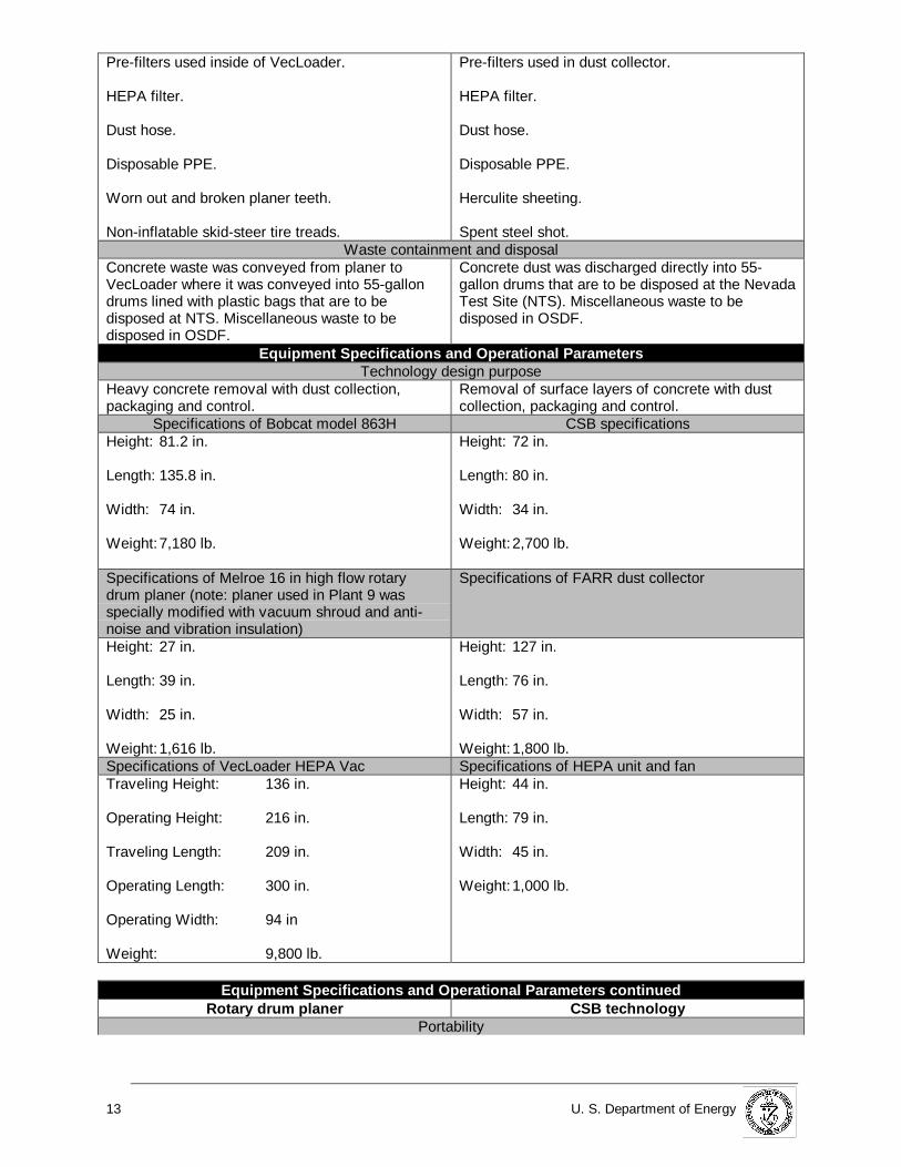
Labor, Support P ersonnel, Specialized Skills and TrainingWork crew
One full time equipment operator.
Two full-time laborers.
One full-time equipment tender (oiler).
One part-time forklift operator.
One CSB operator.
Two full time laborers.
Part time forklift operator.
Additional support personnel utilized during the demonstrationSupport personnel (surveyors) to verify 1 in depthremoval requirement.
Part-time radiological control technician.
Support personnel to conduct DOP testing ofHEPA filter on VecLoader.
Electricians, millwrights and pipe fitters to assistwith assembly and disassembly of equipment.
Mechanic to make repairs to planer and Bobcat.
Health and Safety personnel to perform soundlevel meter surveys and dosimetry and providesafety guidance.
One full-time data taker.
Radiological technician.
Support personnel (surveyors) to verify 1 in depthremoval requirement.
Support personnel to conduct DOP testing ofHEPA filter.
Electricians, millwrights and pipe fitters to assistwith assembly and disassembly of equipment.
Health and Safety personnel to perform soundlevel meter surveys and dosimetry and providesafety guidance.
Specialized skillsOperator experience or training needed to operatethe rotary drum planer and VecLoader.
Operator experience for operating CSB technology
TrainingAll of the subcontractor’s employees received 48 hof FEMP site specific training. Employeesoperating the VecLoader and rotary drum planerwere either previously experienced or receivedtraining from the subcontractor’s personnel whowere previously experienced.
CSB vendor received 48 h of FEMP site specifictraining. FEMP laborers supporting thedemonstration received briefing on the hazards ofthe CSB technology from the vendor.
Waste ManagementPrimary waste generated
Rotary drum planer CSB tec hnologyFine concrete dust and concrete pieces (from 3 into 4 in diameter).
Fine concrete dust packaged in 55-gallon drums.
Waste Management cont inuedRotary drum planer CSB tec hnology
Secondary waste generated
13 U. S. Department of Energy
Pre-filters used inside of VecLoader.
HEPA filter.
Dust hose.
Disposable PPE.
Worn out and broken planer teeth.
Non-inflatable skid-steer tire treads.
Pre-filters used in dust collector.
HEPA filter.
Dust hose.
Disposable PPE.
Herculite sheeting.
Spent steel shot.Waste containment and disposal
Concrete waste was conveyed from planer toVecLoader where it was conveyed into 55-gallondrums lined with plastic bags that are to bedisposed at NTS. Miscellaneous waste to bedisposed in OSDF.
Concrete dust was discharged directly into 55-gallon drums that are to be disposed at the NevadaTest Site (NTS). Miscellaneous waste to bedisposed in OSDF.
Equipment Specifications and Op erat ional P arametersTechnology design purpose
Heavy concrete removal with dust collection,packaging and control.
Removal of surface layers of concrete with dustcollection, packaging and control.
Specifications of Bobcat model 863H CSB specificationsHeight: 81.2 in.
Length: 135.8 in.
Width: 74 in.
Weight:7,180 lb.
Height: 72 in.
Length: 80 in.
Width: 34 in.
Weight:2,700 lb.
Specifications of Melroe 16 in high flow rotarydrum planer (note: planer used in Plant 9 wasspecially modified with vacuum shroud and anti-noise and vibration insulation)
Specifications of FARR dust collector
Height: 27 in.
Length: 39 in.
Width: 25 in.
Weight:1,616 lb.
Height: 127 in.
Length: 76 in.
Width: 57 in.
Weight:1,800 lb.Specifications of VecLoader HEPA Vac Specifications of HEPA unit and fanTraveling Height: 136 in.
Operating Height: 216 in.
Traveling Length: 209 in.
Operating Length: 300 in.
Operating Width: 94 in
Weight: 9,800 lb.
Height: 44 in.
Length: 79 in.
Width: 45 in.
Weight:1,000 lb.
Equipment Specifications and Op erat ional P arameters cont inuedRotary drum planer CSB tec hnology
Portability

U.S. Department of Energy 14
The Bobcat and rotary drum planer can be towedon a suitable trailer by a one-ton or larger truck.The VecLoader HEPA Vac is already mounted ona trailer and can be towed by a one-ton or largertruck.
The CSB technology, dust collector and HEPA unitcan be towed on a suitable trailer by a one-tontruck or hauled on a two-ton or larger truck.
Materials ConsumedRotary drum planer CSB tec hnology
Tungsten-carbide replacement teeth for rotarydrum planer
Steel shot
Teeth were replaced every 40 h; approximately470 teeth consumed for entire project.
800 lb.
Temporary enclosure for VecLoader HEPA Vac Preparing work area2 in x 4 in lumber and nails for framing enclosure.
Herculite sheeting, nylon tie straps, and duct tapefor covering the enclosure.
80 ft of yellow Herculite for constructing a barrier tocontain stray shot.
Personal Protective Equipment (PPE)Reusable yellow coveralls.Reusable yellow rubber shoe covers.Reusable yellow hoods.Disposable yellow shoe covers.Disposable cotton glove liners.Disposable nitrile gloves.Disposable cotton work gloves.Disposable ear plugs.Ear protectionhead phones (reusable).Powered Air Purifying Respirator (PAPR-reusable).Hard Hat (reusable).Breathing zone monitor (reusable).
Reusable yellow coveralls.Reusable yellow rubber shoe covers.Reusable yellow hood.Disposable yellow shoe covers.Disposable cotton glove liners.Disposable nitrile gloves.Disposable cotton work gloves.Disposable ear plugs.Hard Hat (reusable).Powered Air Purifying Respirator (PAPR–reusable).Breathing zone monitor (reusable).Personal Ice Cooling System (PICS) “cool suits” asneeded for heat stress prevention.
Dust hose150 ft of 6 in diameter hose. 75 ft of 6 in diameter, smooth bore dust hose.
FuelDiesel fuel to supply the Bobcat, VecLoader HEPAVac and forklift.
Diesel fuel to supply the generator and aircompressor. Propane to supply the forklift.
Insulation IceFiberglass, rubber and expanding foam insulationfor dampening noise and vibrations from the rotarydrum planer.
2-liter frozen ice bottles to supply cooling for thePICS.
Supporting EquipmentJackhammers Air Compressor
Various size jackhammers used to removeconcrete from around drains, floor bolts and otherobstructions.
1 Ingersoll-Rand 750 cfm diesel powered aircompressor (requirements are 100 cfm @ 50 psi).
Forklifts1 Yale model YA-12 rated at 5,000 lb. 1 Yale model YA-12 rated at 5,000 lb.
1 Hyster model rated at 8,600 lb.Vacuum cart Generator
1 custom fabricated vacuum cart attached to theVecLoader dust hose to vacuum up loose concreteand miscellaneous loose waste.
1 Onan model 067IT diesel generator with 125 kWoutput (requirements are 100 amps, 480 volts,three-phase).
Supporting Equipment continuedRotary drum planer CSB tec hnology
Spare rotary drum planer Manlift

15 U. S. Department of Energy
A spare 16 in high-flow Melroe planer was keptready to keep downtime at a minimum duringmaintenance and breakdowns.
1 Grove model SM 2632E manlift.
Lazy Susan CraneA “Lazy Susan” or rotating turntable was used torotate a pallet, containing four drums, underneaththe VecLoader.
1 mobile 15-ton capacity crane.
Potential Operat ional Con cernsRotary drum planer CSB tec hnology
During rotary drum planer operation During CSB technology operationMoving equipment creates a potential collisionhazard.
Vacuum created by VecLoader can cause looseclothing and even appendages to become trappedin dust hose, causing potential injury.
Communications are impaired when rotary drumplaner and VecLoader are running and areimpaired by respirators and hearing protection.
Escaping shot from underneath the machinerepresents a flying projectile hazard—proper PPEis necessary to prevent eye injuries and welting ofthe skin.
Loose shot laying on un-scabbled concrete(smooth finish) represents an extreme slippinghazard.
Communications are impaired when CSBtechnology and dust collector are running and areimpaired by respirators and hearing protection.
Safety, health and environmentalHigh noise levels.
Heat stress.
A catalytic scrubber was required on the exhaust ofthe Bobcat’s diesel engine to prevent release ofpotentially harmful emissions.
Potential release of radioactively contaminateddust to the environment
High noise levels.
Heat stress.
Potential release of radioactively contaminateddust to the environment.

U.S. Department of Energy 16
SECTION 3
Demonstration Plan
Demonstration Site Description
The CSB demonstration was conducted in accordance with the approved FDF Project Safe Work PlanFor The Demonstration of Centrifugal Shot Blasting Technology, Revision 2, August 19, 1998. The CSBtechnology was demonstrated inside of Fernald’s Plant 8, in the Muffle Furnace Area (process area 4), toremove 1 in of contaminated concrete, over an area of 1,464 ft2. The removal and off-site disposal of thetop 1 in of concrete from the first floor of the Plant 8 Muffle Furnace Area was identified as a requirementin the OU3 Record of Decision for Final Remedial Action (ROD), (DOE, 1996), along with other areas inOU3 (Plant 9) containing the highest levels of technetium-99 in debris. Plant 8, the Scrap RecoveryPlant, is a two-story structure measuring 239 ft x 280 ft x 37 ft high and consists of a structural steelframe on a reinforced poured concrete foundation with reinforced concrete ground floors, transite interiorand exterior siding panels (insulation material between panels), and transite roof panels.
The rotary drum planer, for the surface removal of concrete, was operated in accordance with the NSCEnergy Services Surface Removal Of Concrete At Thorium/Plant 9 Complex, 1998. The rotary drumplaner was used to remove 1 in of concrete inside of Fernald’s Plant 9, in process areas 2 and 4 over anarea of 22,600 ft2. Plant 9 (Special Products Plant), was a single-level, irregularly shaped building,measuring approximately 200 ft x 260 ft x 20 ft high. Plant 9 consisted of a structural steel frame withtransite siding and roofing panels and a poured concrete base and floor.
Concrete in each of the locations was similar in cube compressive strength as measured by a GilsonModel HM-75 rebound hammer. The average cube compressive strength measured in Plant 9 was 8,890psi, while the average cube compressive strength measured in the Muffle Furnace Area of Plant 8 was8,700 psi with a variation of 1,100 psi for both areas. The aggregate uncovered in Plant 9 was slightlysmaller (1/2 in to 1.25 in diameter) versus the aggregate uncovered in Plant 8 (3/4 in to 2 in diameter).
Demonstration Objectives
The primary reason for demonstrating the CSB technology was to assess its ability to remove 1 in ofsurface concrete, in a safer, more efficient and productive fashion than other methods. The objectives ofthe demonstration were to determine the CSB technology’s ability to:
• reduce the quantity of concrete for off-site disposition (i.e., top 1 in versus the whole slab);
• remove 1 in of concrete more productively than other methods;
• reduce the amount of secondary waste generated during the process;
• remove concrete more cost effectively than other methods and;
• provide a direct comparison to other concrete removal technologies.
Demonstration Boundaries
The specific scope of work for the CSB technology was the removal of the top 1 in of concrete on thefirst floor of the Muffle Furnace Area (process area 4) of Plant 8, an area having dimensions of 31 ft x 55ft, or 1,705 ft2. Due to fixed pillars, steel floor drains, and raised piers supporting the legs of the MuffleFurnace, only 1,611 ft2 had concrete that could be scabbled. The frame, sheet-metal, and other featureson the CSB prevented it from scabbling concrete flush with vertical surfaces. This aspect, know as astandoff distance meant that the CSB removed 1 in of concrete from 1,464 ft2 of the 1,611 ft2 in theMuffle Furnace Area. Removal of the remaining concrete will occur during the D&D of Plant 8. Although
PERFORMANCE

17 U. S. Department of Energy
the CSB technology was only used to remove concrete, the vendor reported that the machine is alsocapable of cleaning flat, plate steel as well. At this time, the CSB technology is not capable of removingconcrete on vertical or non-flat surfaces. Figure 9 depicts the CSB technology in operation in Plant 8.
The rotary drum planer was utilized to remove 1 in of concrete on the first floor of Plant 9, in process
areas 2 and 4 (enriched uranium casting and uranium machining areas, respectively), over an area of22,600 ft2. In addition to removing concrete, the rotary drum planer is also capable of removing asphalt,although it was not used for this task at Fernald.
Results
The CSB technology
After the CSB removed the first 1/4 in to 3/8 in of concrete, the aggregate, consisting of large diameterriverine pebbles, started to be exposed. The riverine pebbles proved to be much harder than thesurrounding concrete matrix and were much harder to wear away. The matrix surrounding the riverinepebbles was more easily removed via the CSB technology; however, the pebbles tended to remain untilthe surrounding matrix was completely removed. Significantly greater quantities of riverine pebbles wereencountered as the depth approached 1 in. These riverine pebbles were much stronger than thesurrounding matrix and their removal was mostly as a result of erosion of the surrounding concretematrix by steel shot rather than fragmentation of the stone itself.
Due to the rough (large, exposed pebbles) surface left after removing approximately 1/2 in of concrete,the CSB technology had difficulty traversing the exposed subsurface. The CSB technology was equippedwith hard rubber tires, similar to the type found on a grocery cart, which would easily become stuck onthe exposed pebbles. The operator would have to compensate for the stuck wheel by increasing thespeed of the hydraulic drive on the side that was stuck in order to move the machine. This phenomenon
Figure 9. CSB technology op erat ing in Fernald's Plant 8.

U.S. Department of Energy 18
would leave the floor uneven and cause the CSB technology to “crab-walk” across the floor, exacerbatingthe situation. Eventually, the wear and tear caused from traversing the rough, uneven floor, caused thehydraulic pump, which powered the hydrostatic drive, to fail.
For most of the Muffle Furnace Area, the CSB technology had to make on average, ten passes toachieve the 1 in removal requirement. However, in one small area approximately 2 ft by 10 ft where theoriginal floor had been replaced with newer, softer concrete, the CSB technology achieved the 1 inremoval requirement in only 3 passes.
The rotary drum planer
The rotary drum planer removed at least 1 in of concrete over 22,600 ft2 in Plant 9, achieving aproduction rate of 52.2 ft2/hr. More capable of removing 1 in of the FEMP’s concrete than the CSBsystem, the rotary drum planer system also suffered fewer breakdowns, cost less per unit area to operateand had a stronger dust collection system than the CSB technology. Figure 10 depicts the rotary drumplaner operating in Fernald's Plant 9.
The waste created by the rotary drum planer was a combination of concrete dust and chunks up to 4 indiameter, which resulted in less efficient waste packing than the dust created by the CSB.
The rotary drum planer achieved the 1 in removal requirement in only 1 pass. In fact, the challenge forthe operator of the rotary drum planer was to keep the depth above 2 in to attain a higher productivityand to reduce the quantity of waste generated. As concrete removal operations progressed in Plant 9,the operators of the rotary drum planer became more adept at maintaining removal depths to between1.5 in and 2 in.
When encountering reinforcing steel bar, anchor bolts, or wire mesh less than 1 in from the surface, the
rotary drum planer would break off its tungsten-carbide teeth, causing a breakdown. The rotary drumplaner system also experienced difficulties when it encountered concrete reinforced with a rubber mesh
Figure 10. Rot ary drum planer operat ing inFernald's Plant 9.

19 U. S. Department of Energy
substance. The planer would remove the concrete and rubber mix, but the resulting waste would plug inthe dust hose leading to the VecLoader. After a loss of vacuum at the planer was noticed, scabblingoperations would cease until D&D laborers using sledgehammers could jolt the clogs loose.
After scabbling for several weeks, the Plant 9 subcontractor purchased and modified a second planer sothat during maintenance or breakdowns, the planers could be exchanged, increasing productivity.
The noise generated by the rotary drum planer was greater than that generated by the CSB technology,although the evaluation of worker noise exposure was limited to a representative characterization.Additional exposure monitoring would be required to more accurately reflect worker noise exposureconditions. Table 3 compares key operational and performance factors between the two concreteremoval technologies.
Table 3. Comparison of key operat ional and perfo rmance factors for the CSB tec hnology androtary drum planer system
CSB Technology Rot ary Drum Planer SystemArea of concrete removed to 1
in depth1,464 ft2 22,600 ft2
Number of passes re quired toachieve 1 in removal
requirement
Average of 10 1
Number of 55-gallon drums ofconcrete waste generated;estimated to be 5.88 ft 3 of
waste per drum
35 779
Drums of waste generated perft 2 of concrete sca bbled
0.024 0.034
Type of Secondary wastegenerated
8 pre-filters, 1 HEPA filter, 75 ftof 6 in diameter dust hose, misc.disposable PPE
28 pre-filters, 1 HEPA filter, 1 setof tire treads for skid-steer, 150 ftof 6 in diameter dust hose, misc.disposable PPE
Man hours required forremoval
191 h 1,885 h
Crew hours required forremoval
86 h 449 h
Production rate (ft 2/crew h) 17.7 ft2/ha 52.2 ft2/ha
Crew size 3.25b 4.2c
Noise level 88 dBAd 98 dBAe
Airborne radioactivity levelsdetected
The Derived Air Concentration (DAC) values reported were for U-238because U-238 was the isotope of concern in both areas. All samplesshowed scabbling activities emitted less than 10% DAC except onewhich was reported at 16.09 DAC. Greater than 10% DAC is theaction level for respiratory protection at the FEMP. As an addedsafety precaution, workers in both areas were wearing Powered AirPurifying Respirators (PAPRs).
Standoff distance from verticalsurfaces
4 in – 6 in 6 in – 10 in
CSB Technology Rot ary Drum Planer SystemDevelopment status Commercially available Components commercially
available, but specialmodifications made by NSCEnergy Services to operate in aradiological environment.
Floor condition after scabbling Between 1/16 in and 3/16 in, theCSB technology leaves the
Floor is left rough with groovemarks running parallel to the

U.S. Department of Energy 20
surface slightly rough, but in acondition suitable for re-using. Atdepths greater than 1/4 in, thesurface becomes increasinglyrougher.
direction of scabbling.
PPE Single set of PPE, including asingle set of hearing protection.
Single set of PPE with doublehearing protection.
Ease of Use Vendor training or priorexperience running CSBtechnology required.
Vendor training or priorexperience running equipmentrequired.
Health and Safety Flying shot represents a potentialsafety hazard and loose shot onun-scabbled floor represents anextreme slipping hazard.
High noise level and strongvacuum created by VecLoaderrepresents potential healthhazards.
a – production rates based on total area of concrete required to be scabbled.b – 0.25, is equal to the amount of time required of a forklift operator to support the demonstration.C - 0.2 is equal to the amount of time required of a forklift operator to support the rotary drum planer.d – Based upon the average of three noise dosimetry measurements ranging in duration fromapproximately 5.5 h to 8.5 h.e – Based upon one noise dosimetry measurement with a duration of approximately 3.5 h.

21 U. S. Department of Energy
SECTION 4
Competing Technologies
The rotary drum planer was the baseline technology to which the CSB technology was compared duringthe demonstration. However, there are many other concrete removal technologies on the market. At theFEMP, the process had to be dustless and not require the use of water. Some of the other technologieslisted below are capable of removing concrete, but create dust or use water. Some of the othertechnologies also create a considerable amount of secondary waste, such as water or chemical waste.
Other concrete removal tec hnologies:
• diamond wire sawing• scarifiers (Pentek Moose®)• jack-hammering• large pneumatic concrete breakers and crushers mounted on heavy equipment to break up and
remove entire concrete pad• grit blasting• high pressure and ultra-high pressure water blasting• wet ice blasting
The advantages of the CSB technology o ver the rotary drum planer: • greater maneuverability• more precise in removing thin layers of concrete• at depths between 1/16 in and 3/16 in, it leaves the floor in re-usable condition• generates less waste per unit area due to the dust-like nature of the concrete waste• can blast over floor drains, rebar, wire mesh, etc,
The disadvantages of the CSB technology:
• flying shot creates a potential safety hazard• loose shot on finished floor surfaces represents a slipping hazard• not adept at removing more than 3/4 in over a large area• operating costs are more expensive compared to the rotary drum planer• production rate slower compared to the rotary drum planer
The advantages of the rotary drum planer over the CSB tec hnology:
• faster production rate• lower operating costs• more rugged; operated for longer periods of time without breakdowns
The disadvantages of the rotary drum planer:
• not as precise at removing thin layers of concrete, i.e., ≤ 3/16 in• ineffective if rebar, wire mesh or floor anchors are in proximity to surface• cannot remove concrete close to floor drains, or operate over them• cannot operate very effectively in small or cluttered spaces
TECHNOLOGY APPLICABILITY ANDALTERNATIVES

U.S. Department of Energy 22
Technology Applicability
Both the CSB and rotary drum planer are commercially available and fully mature. The rotary drumplaner system, however, was specially modified to allow for dust and waste collection with thesimultaneous drumming of waste. Both systems’ dust collectors were fitted with a nuclear grade HEPAfilter capable of removing ≥ 99.97% of all particles larger than 0.3 microns. The CSB technology wasinitially designed to remove the mastic off of aircraft carrier decks. Since then, however, the technologyhas been used to remove floor coatings, roughen slippery floor surfaces, and prepare floor surfaces fornew coatings or substances. Concrete Cleaning Inc., the vendor who operated the CSB technology at theFEMP, reports that the machine is capable of cleaning flat plate steel as well as concrete.
The rotary drum planer technology has been widely used for the removal of concrete and asphalt inhighways and parking lots for many years. The VecLoader HEPA Vac has been utilized in the asbestosabatement business and in the industrial sector for the removal of many different types of loose materialfor a considerable time. Both the rotary drum planer and the VecLoader HEPA Vac are self-powered andeasily transported. These features make this system ideal for heavy concrete or asphalt removal inrelatively large areas where the utilities have been disconnected. For health and safety purposes, theVecLoader should be isolated to minimize loud noise sources in the work area. If the skid-steer used torun the rotary drum planer is diesel, then a catalytic scrubber is needed on the exhaust system to limitthe emission of harmful substances.
Patents/Commercialization/Sponsor
The CSB technology demonstrated at the FEMP was manufactured by Georg Fischer Disa Goff, Inc. ofSeminole, Oklahoma. The manufacturer also makes different models of both portable and stationaryshot blasting equipment. The dust collector used in the CSB demonstration was manufactured by FARRCompany of Los Angeles, California. Concrete Cleaning Inc., of Otis Orchards, Washington was thevendor who performed the concrete removal using the CSB technology. The CSB technologydemonstration was sponsored by the DOE’s Office of Science and Technology, Large ScaleDemonstration and Deployment Project. No regulatory permits were required to demonstrate the CSBtechnology at the FEMP.
The Bobcat skid steer loader and rotary drum planer used at the FEMP were manufactured by theMelroe Company of Fargo, North Dakota. The VecLoader HEPA VAC was manufactured by VectorTechnologies, Ltd., of Milwaukee, Wisconsin. NSC Energy Services was the Fernald Plant 9 D&Dsubcontractor, who specially modified and coupled the two technologies together to offer a safe andefficient dust free process. No regulatory permits were required to operate the rotary drum planer systemat the FEMP.
Technology contacts:
CSB TechnologyGeorg Fischer Disa Goff, Inc.P.O. Box 1607Seminole, Oklahoma 74868Ph. 405-382-6900http://www.goff.thomasregister.com
CSB Dust CollectorFARR Company2201 Park PlaceEl Segundo, California 90245Ph. 310-727-6300http://www.farrco.com
Technology contacts continued

23 U. S. Department of Energy
Bobcat skid steer and Melroe PlanerMelroe CompanyP.O. Box 6019Fargo, North Dakota 58108Ph. 701-241-8700http://www.bobcat.com
VecLoader HEPA VacVector Technologies, Ltd.6220 North 43rd StreetMilwaukee, Wisconsin 53209Ph. 800-832-4010http://www.vector-vacuums.com

U.S. Department of Energy 24
SECTION 5
Methodology
A cost analysis was performed to evaluate and summarize the CSB technology against the rotary drumplaner for removing the top 1 in of concrete floors contaminated with technetium-99. The objective is toassist decision-makers who are selecting from among competing technologies. This analysis strives todevelop realistic estimates that represent actual D&D work within the DOE weapons complex. However,this is a limited representation of actual cost, because the analysis uses only data observed during thedemonstration. Some of the observed costs were eliminated or adjusted to make the estimates morerealistic. These adjustments were allowed only when they would not distort the fundamental elements ofthe observed data (i.e. does not change the production rates, quantities, work element, etc.,) andeliminated only those activities which are atypical of normal D&D work. Descriptions contained in laterportions of this analysis detail any changes to the observed data.
This cost analysis compares the CSB technology to a rotary drum planer modified by a D&D contractor.The CSB was demonstrated in Fernald’s Plant 8, while the rotary drum planer was demonstrated inFernald’s Plant 9. The Technetium-99 contaminated concrete removed during the demonstrations wasloaded into 55-gallon drums and will be disposed at the Nevada Test Site. The rotary drum planer wasassembled from commercially available components and demonstrated by a D&D contractor. SurfaceRemediation Specialists demonstrated CSB with support from FDF. The CSB equipment was included aspart of a vendor-provided service.
FDF observed both demonstrations. For CSB, a representative of FDF monitored the demonstrationsand collected cost and performance data. For the Rotary Drum Planer, the D&D contractor conductingthe demonstration collected the cost and performance data, with quality assurance oversight provided byFDF.
Cost Analysis
The following cost elements were identified in advance of the demonstrations, and data were collected tosupport a cost analysis based on those elements: • mobilization (including necessary training)• monitoring, sampling, testing, analysis (including DOP tests)• D&D work (including surveying for verification of removal depth)• waste disposal• demobilization (including equipment decontamination)• personal protective equipment
Mobilization includes the cost of getting technology equipment to the site, costs for training D&D workerson use of the technology equipment, costs for training vendor personnel, installation of temporary workareas, and installation of temporary utilities. The initial DOP test of filter systems is also included.
Monitoring, testing, sampling and analysis include the cost of performing DOP tests on the filter systemsfor each HEPA filter change.
D&D work includes removal of 1 in of contaminated concrete from the floors of Plants 8 and 9. Surveywork to verify the depth of concrete removal is also included.
Waste disposal includes the cost of shipping all primary and secondary waste streams to the NevadaTest Site. Cost data for disposal at NTS were provided by FDF and are derived from historical data. Costfor disposal of the remaining concrete in the OSDF was not included because the cost would be almostthe same for both technologies on a ft2 basis; the following scenario illustrates this point. Assuming the
COST

25 U. S. Department of Energy
rotary drum planer removed 3 in instead of the required 1 in (most areas between 1.5 in and 2 in depth),the thickness of the pad would be 21 in whereas the thickness of the pad remaining in Plant 8 would be23 in because the CSB technology was more exact in removing only 1 in. The cost to dispose of an inplace yd3 of material in the OSDF is $7.50 or $.28 per ft3. Therefore, the cost difference for disposing theremaining concrete slab in the OSDF is 2 in per ft2 or .17 ft3, which equates to the disposal cost beingonly $.05 more per ft2 for the CSB technology.
Demobilization includes removal of temporary work areas and utilities, decontamination of technologyequipment, disposal of wastes generated by removal of temporary work areas and utilities andtechnology equipment decontamination and removal of technology equipment from the site. The finalDOP test is also included.
PPE costs include all clothing, respirator equipment, etc., required for protection of crewmembers duringthe demonstration. It was assumed that four changes of reusable PPE clothing items per day wererequired for each crewmember. Reusable PPE items were assumed to have a life expectancy of 200 h.The cost of laundering reusable PPE clothing items is included in the analysis. It was assumed that fourchanges of disposable PPE clothing items per day were required for each crew member. DisposablePPE items were assumed to have a life expectancy of 10 h (the shift length).
Comparative unit costs were determined per ft2 of floor remediated.
Based on observation, the following modifications were made to cost and performance data to reflect amore realistic deployment of the technologies. Because of the huge difference in the areas remediatedby the two technologies, the variable costs (dependent on areas remediated) for CSB were prorated tothe same quantity as the rotary drum planer (22,600 ft2). The rotary drum planer initially showed aproduction rate of 15.8 ft2/h, which was less than CSB. This low production was due to the shutdown timerequired for planer maintenance. The D&D contractor countered this low production by adding a secondplaner to the crew. Thus, when the planer in use required maintenance, it could be quickly changed out.This additional planer boosted production to 52.2 ft2/h. Because this is a modification that any prudentD&D contractor would make, the cost analysis for the rotary drum planer was based on use of twoplaners. The make-up and size of crews for both technologies are for a typical deployment of thetechnologies.
Cost Conclusions
A comparison of the major cost elements for removing one inch of contaminated concrete is shown inTable 4.
Table 4. Summary Cost Comparison
CENTRIFUGAL SHOT BLASTING(Innovative)
ROTARY DRUM PLANER(Baseline)
Cost Driver Unit Cost ProductionRate
Cost Driver Unit Cost ProductionRate
Mobilization1 $9,500 N/A Mobilization1 $3,386 N/ATesting2 $586 N/A Testing2 $195 N/AD&D Work $30.21/ft2 17.7 ft2/h D&D Work $4.30/ft2 52.2 ft2/hWaste Disposal $2.23/ft2 N/A Waste Disposal $3.35/ft2 N/ADemobilization1 $6,195 N/A Demobilization1 $5,895 N/APPE $1.82/ft2 N/A PPE $1.79/ft2 N/A1 Total costs that are independent of the quantity of D&D work.
2 Includes tests at each change of HEPA filters. Initial and final DOP tests are included in Mobilization and
Demobilization.
Waste disposal costs were slightly higher for the rotary drum planer because it typically removedconcrete to a greater depth than did CSB, thus generating a greater volume of waste. The rotary drumplaner had less control over the depth of concrete removed than the CSB technology.
Demobilization costs were significantly higher for CSB due to the cost of equipment decontamination.

U.S. Department of Energy 26
PPE costs were less for the rotary drum planer because it had a higher production rate. This shortens theduration required to remediate a given area and thus requires less PPE. Both technologies requiredessentially the same PPE system. The rotary drum planer required double hearing protection; however,the impact on unit cost was insignificant.
The comparative unit costs for the two technologies for the demonstrated application are:
$9.44/ft2 - Rotary Drum Planer
$34.25/ft2 - Centrifugal Shot Blasting
Therefore, for removal of the top 1 in of contaminated concrete floor slabs, CSB is more costly than therotary drum planer. CSB was more costly for mobilization, D&D work, demobilization and personalprotective equipment.
Because CSB showed no cost advantage over the rotary drum planer, no break-even or paybackanalyses were performed.

27 U. S. Department of Energy
SECTION 6
Regulatory Considerations
The operation of the CSB technology and the rotary drum planer at the FEMP were governed by thefollowing health and safety regulations:
• Occupational Safety and Health Adm inistration (OSHA) 29 CFR 1926
1926.300 to 1926.307 Tools-Hand and Power 1926.400 to 1926.449 Electrical – Definitions 1926.28 Personal Protective Equipment 1926.52 Occupational Noise Exposure 1926.102 Eye and Face Protection 1926.103 Respiratory Protection
• OSHA 29 CFR 1910
1910.101 to 1910.120 (App E) Hazardous Materials1910.211 to 1910.219 Machinery and Machine Guarding1910.241 to 1910.244 Hand and Portable Powered Tools and Other Hand-Held
Equipment
1910.301 to 1910.399 Electrical – Definitions1910.95 Occupational Noise Exposure1910.132 General Requirements (Personal Protective Equipment)1910.133 Eye and Face Protection1910.134 Respiratory Protection1910.147 The Control of Hazardous Energy (Lockout/Tagout)
• 10 CFR 835 Occupational Radiation Protection
Disposal requirements/criteria inc lude the following issued by the U.S. Department ofTransportation (DOT) and DOE:
• 49 CFR Subchaptor C Hazardous Materials Regulations
171 General Information, Regulations and Definitions172 Hazardous Materials Table, Special Provisions, Hazardous
Materials Communications, Emergency Response Informationand Training Requirements
173 Shippers – General Requirements for Shipments and Packaging174 Carriage by Rail177 Carriage by Public Highway178 Specifications for Packaging
• 10 CFR Subchapter 1 Packaging and Transportation of Radioactive Material
Fernald site specific requirements
REGULATORY AND POLICY ISSUES

U.S. Department of Energy 28
• RM – 0021 Fluor Daniel Fernald Safety Performance Requirements Manual.
• DOE order 440.1A Worker Protection Management for DOE Federal andContractor
Employees.
If the waste is determined to be hazardous solid waste, the following Environmental Protection Agency(EPA) requirements should be considered:
• 40 CFR Subchapter 1 Solid Waste
Before either the CSB technology or the rotary drum planer could be operated at the FEMP, a number ofsite-specific requirements had to be fulfilled. Those requirements were as follows:
• An approved Safe Work Plan• Complete a Project Evaluation For Air Permit/Notification Requirements – Checklist• An approved Waste Management Plan• Complete a Clean Air Act Assessment of potential radionuclide emissions during operations• Complete a Nevada Test Site (NTS) Waste Acceptance Criteria Form• Complete an Environmental As Low As Reasonably Achievable (ALARA) Review/Evaluation –
Report And Check List• Apply and receive an Approved Site Safety Assessment
Safety, Risks, Benefits, and Community Reaction
Since both the CSB and rotary drum planer technologies were designed for the decontamination ofconcrete floor surfaces, there is no regulatory requirement to apply CERCLA’s nine evaluation criteria.Nonetheless, some evaluation criteria are discussed below. Other criteria such as cost and performancewere discussed in Sections 3 and 5.
Worker Safety (CSB tec hnology)
With respect to the CSB technology, flying shot escaping from underneath the machine and loose shotlaying on smooth surfaces represent hazards to workers. Better seals need to be developed to preventthe shot from escaping underneath the machine when it is in operation. Instead of using the rubber seals,which quickly come out of adjustment and let shot escape, a better approach might be to use a “chainskirt” around the bottom of the machine. These “chain skirts” have been used for many years byagricultural machine manufacturers to prevent objects from flying out underneath chopper-type mowers.A “chain skirt” for the CSB technology, however, would consist of much smaller diameter chain than thatused on a large chopper type mower, and would be several rows deep to contain the shot. Anotheradvantage of the “chain skirts” is that they continue to provide coverage when the machine is traversingover uneven surfaces.
At the FEMP, a herculite shield was erected on stanchions around the work area to keep the loose shotoff pathways and other areas outside of process area 4. Additionally, one laborer continuously pushedthe shot collection-magnet over any areas with smooth surfaces. Loose shot on rough surfaces, such asthose previously blasted did not represent a slipping hazard.
Worker Safety (rotary drum planer)
The powerful vacuum created at the end of the dust hose by the VecLoader represents a potential safetyhazard to workers. Should the dust hose make a complete seal around an appendage, allowing thevacuum to reach maximum potential, then the possibility of serious injury increases. This can beprevented by a couple of simple measures such as using an angled dust hose tip and/or having a tenderin radio contact at the VecLoader at all times. Another potential risk to workers is the buildup of carbonmonoxide or other harmful emissions from the skid-steer running the planer. In Plant 9, NSC EnergyServices lessened these risks by installing a catalytic scrubber on the exhaust of the skid-steer and set

29 U. S. Department of Energy
up carbon dioxide and carbon monoxide monitors inside of the work area. There were no reportedproblems with emissions during scabbling operations in Plant 9. Noise levels generated by both therotary drum planer and VecLoader are potentially injurious and appropriate hearing protection measuresmust be utilized.
Community Safety, Community React ion and Socioeconomic Impacts
The use of either the CSB or rotary drum planer technologies would have no measurable impact oncommunity safety or socioeconomic issues. Community reaction to the two technologies would likely bepositive since they are useful tools in helping to remediate the site. Additionally, by removing andsending only the top 1 in of concrete off-site for disposal, the DOE and taxpayer can expect significantcost savings.
Environmental Impact
The only potential negative environmental impact that could occur with either technology would be arelease of contaminated dust to the environment by the dust collectors. However, this event would behighly unlikely, because the dust collector for the CSB technology was located inside of Plant 8 and theVecLoader HEPA Vac was located inside of a containment structure. A potential release of dust wasmade even more unlikely by electrical lockouts on the dust collectors, which prevented the scabblingtechnologies from operating in the event of a dust collector failure.

U.S. Department of Energy 30
SECTION 7
Implementation Considerations
The CSB technology, FARR dust collector, rotary drum planer, Bobcat skid steer and VecLoader HEPAVac are commercially available systems. The rotary drum planer system was specially modified by NSCEnergy Services to operate in a nuclear environment, providing dustless operation with simultaneouscollection and bagging of waste. Each technology was operated by experienced personnel, with manyyears experience in their respective fields. Due to the complicated nature of each technology and theprocess knowledge needed to remove concrete safely and efficiently in a radiological environment, it isnot recommended that either concrete removal process be attempted by inexperienced vendors.
Another factor to consider when undertaking a concrete removal process is not only determining thestrength of the concrete to be removed but also its composition. The natural riverine pebbles turned outto be much harder than the surrounding concrete matrix leading to slower than expected productionrates. The large riverine pebbles were also detrimental to the shot recycling mechanism, steering, andthe hydrostatic drive of the CSB technology. Had the composition of the concrete been identified prior tothe demonstration, adaptations such as using a larger sized shot and pneumatic tires could have beentaken to compensate.
Technology Limitations and Needs for Future Development
The CSB technology and dust collector demonstrated at the FEMP could benefit from the followingdesign improvements.
• An improved seal, such as a “chain skirt,” around the bottom of the machine to prevent flying shotfrom escaping.
• A more powerful dust collector capable of generating greater airflow and vacuum. The dust collectorused during the demonstration did not generate the required vacuum or airflow (12 in water, and2,000 cfm are recommended by the CSB manufacturer).
• A better waste-to-drum transfer system on the dust collector; when full drums where removed fromunderneath the dust collector, residual dust would fall out of the dust collector, even after the flowgates had been tightly shut.
• An improved shot recycle mechanism, whereby more shot is captured by the machine instead ofbeing left on the floor.
NSC Energy Service made design changes to the rotary drum planer system during the course ofscabbling 22,600 ft2 of concrete that made remarkable improvements in productivity. Thoseimprovements included:
• Making available a second planer to utilize during breakdowns and regularly scheduled maintenance.
• Using flat, rubber treads instead of tires to eliminate harmonic distortions created during scabbling.
• Using a high-flow hydraulic model skid-steer to properly operate the planer attachment.
Technology Selection Considerations
For concrete removal at depths equal to or greater than 3/16 in, in relatively large open areas, the rotarydrum planer is the recommended technology. For concrete removal at depths between 1/8 in and 3/16 in
LESSONS LEARNED

31 U. S. Department of Energy
and in confined areas, even at 1 in depth, the CSB technology is recommended because it has greatermaneuverability and generates less waste per unit area.

U. S. Department of Energy A-1
APPENDIX A
Fluor Daniel Fernald (FDF), May 1993. Operable Unit 3 (OU3) Work Plan Addendum, RemedialInvestigation Feasibility Study (RI/FS). Volume 2 of 2.
Fluor Daniel Fernald (FDF). 1998. Technology Evaluation White Paper Report; Centrifugal Shot BlastingFor Heavy Concrete Scabbling. FDF.
Fluor Daniel Fernald (FDF). August 1998. Project Safe Work Plan For The Demonstration of CentrifugalShot Blasting Technology. Revision 2. FDF.
Fluor Daniel Fernald (FDF). October 1998. Project Completion Report For Surface Concrete RemovalDemonstration In The Plant 8 Muffle Furnace Area. FDF.
Melroe Company. 1999. Melroe Bobcat Skid-Steer Loaders and Melroe Attachments. Melroe Company.World Wide Web. http://bobcat.com.
NSC Energy Services (NSC). 1998. Surface Removal of Concrete At Thorium/Plant 9 Complex. NSCEnergy Services.
U.S. Army Corps of Engineers (USACE). 1996. Hazardous, Toxic, and Radioactive Waste RemedialAction Work Breakdown Structure and Data Dictionary. USACE.
U.S. Army Corps of Engineers (USACE). August 1995.Construction Equipment Ownership and OperatingExpense Schedule. Region II, USACE.
REFERENCES

B-1 U. S. Department of Energy
APPENDIX B
Acronym/Abbreviat ion Description
ALARA As Low As Reasonably AchievableCERCLA Comprehensive Environmental Response, Compensation & Liability Actcfm cubic feet per minuteCFR Code of Federal RegulationsCSB Centrifugal Shot BlastingD&D Decontamination & DecommissioningDOE U.S. Department of EnergyDOP Dioctyl PhthalateDOT U.S. Department of TransportationEPA Environmental Protection AgencyFDF Fluor Daniel FernaldFEMP Fernald Environment Management Projectft foot/feetft2 square feetHEPA High Efficiency Particulate Air filterhp horsepowerh hourin inchLSDDP Large Scale Demonstration and Deployment ProjectM&I Management and IntegrationNTS Nevada Test SiteOSDF On Site Disposal FacilityOSHA Occupational Safety and Health AdministrationOST U.S. DOE’s Office of Science and TechnologyOU3 Operable Unit 3PAPR Powered Air Purifying RespiratorPPE Personal Protective Equipmentpsi pounds per square inchSAE Society of Automotive EngineersROD Record of DecisionUSACE United States Army Corps of Engineers
LIST OF ACRONYMS AND
ABBREVIATIONS

U.S. Department of Energy
APPENDIX C
This sheet summarizes the fixed costs. It represents the start-up costs necessaryto deploy a technology.
ID Description Quantity Unit Output Manhrs Labor E quipmnt Materials Other Total
Planing ( Baseline) 22600 SF01 Mobilization 1 EA 8 $1,046 $0 $0 $2,340 $3,3802 Monitoring, Sampling, Testing 1 EA 8 $195 $0 $0 $0 $19521 Demobilization 1 EA 8 $195 $0 $0 $5,700 $5,89
Total Planing 22600 SF 24 $1,436 $0 $0 $8,040 $9,47
Shot Blasting (Innovative) 22600 SF01 Mobilization 1 EA 0 $0 $0 $0 $9,500 $9,5002 Monitoring, Sampling, Testing 1 EA 24 $586 $0 $0 $0 $58621 Demobilization 1 EA 8 $195 $0 $0 $6,000 $6,19
Total Shot Blasting 22600 SF 32 $781 $0 $0 $15,500 $16, 2
SUMMARY OF COST ELEMENTS

B-1 U. S. Department of Energy
This sheet summarizes the scaleable costs (costs dependent on quantity)
Description Quantity Unit Output Manhrs Labor E quipmnt Materials Other Total
laning ( Baseline) 22600 SFlaning 1-in From Conc. Floor 22600 SF 1885 $46,061 $20,279 $30,736 $0 $97,076isposal 22600 SF 0 $0 $0 $0 $75,711 $75,711PE 22600 SF 0 $0 $0 $0 $40,528 $40,528
otal Planing 22600 SF 1885 $46,061 $20,279 $30,736 $116,239 $213,315
hot Blasting (Innovative) 22600 SFlasting 1-in From Conc. Floor 22600 SF 2963 $72,221 $1,815 $53,336 $555,282 $682,654isposal 22600 SF 0 $0 $0 $0 $50,386 $50,386PE 22600 SF 0 $0 $0 $0 $41,041 $41,041
otal Shot Blasting 22600 SF 2963 $72,221 $1,815 $53,336 $646,709 $774,081

U.S. Department of Energy
This sheet summarizes the total costs incurred for the CSB demonstration andthe rotary drum planer
Description Quantity Unit Output Manhrs Labor E quipmnt Materials Other Total
laning ( Baseline) 22600 SFMobilization 1 EA 8 $1,046 $0 $0 $2,340 $3,386Monitoring, Sampling, Testing 1 EA 8 $195 $0 $0 $0 $195
laning 1-in From Conc. Floor 22600 SF 1885 $46,061 $20,279 $30,736 $0 $97,076isposal 22600 SF 0 $0 $0 $0 $75,711 $75,711emobilization 1 EA 8 $195 $0 $0 $5,700 $5,895PE 22600 SF 0 $0 $0 $0 $40,528 $40,528
otal Planing 22600 SF 1909 $47,497 $20,279 $30,736 $124,279 $222,791
hot Blasting (Innovative) 22600 SFMobilization 1 EA 0 $0 $0 $0 $9,500 $9,500Monitoring, Sampling, Testing 1 EA 24 $586 $0 $0 $0 $586
lasting 1-in From Conc. Floor 22600 SF 2963 $72,221 $1,815 $53,336 $555,282 $682,654isposal 22600 SF 0 $0 $0 $0 $50,386 $50,386emobilization 1 EA 8 $195 $0 $0 $6,000 $6,195PE 22600 SF 0 $0 $0 $0 $41,041 $41,041
otal Shot Blasting 22600 SF 2995 $73,002 $1,815 $53,336 $662,209 $790,362