ANDRITZ centrifugal pump - ACP/ARE series · ANDRITZ centrifugal pump ACP/ARE series
description

Pump is an important rotating equipment which you will come across all type of industry. Pump section,
performance. Installation of pump to get desired performance and connection of pump piping. We can
understand classification , working and standard engineers practice of pump from this article.
Terms to Remember :
Pump type, Head, Head loss , NPSH.
Sizing of centrifugal pump:
The centrifugal is like the ‘WORK HORSE’ in a process industry. The following figure shows major
components in a centrifugal pump.
Liquid is pressured in to the suction of pump where the impeller imparts a centrifugal velocity to the fluid. As
the liquid discharges from the pump its velocity head converts to pressure head because of typical shape of
the casing.
Pumps are usually specified early in the Process Schedule , when lines are ‘SKETCHILY’ located and sized
when control valves have not been Sized and when pump performances must be estimated rather than
established .
A complex relationship exists between the system head, Pump head and valve drop
characteristics .Methods of selecting control valve drop and impeller performance are not readily
Systematized .API-610 fixed many mechanical and procedural details and it is often included in all
Refinery/Petrol chemical industries when pumps are specified.
A Design Engineer must consider two characteristics of a centrifugal pump., their discharge pressure and
volumetric flow rate through them. The designer’s heat and material balance will give the required flow rate
hydraulic Calculations will dictate the head.
1. HOW TO CALCULATE FLOW REQUIRED?
The kg/hr of liquid to be pumped is calculated from heat and material balance.

Case-1
Suppose we have a simple equation
HCL+ NaOH = = > NaCL + H2O
= = => (1 mole + 1 mole = = => 1 mole + 1 mole ) Mol. wts
= = => 36.5 kg + 40 kg = = => 58.5 kg+18 kg .
Hence for manufacturing 100 kg of NaCL you have to pump 62.40 kg of HCL &
68.37 kg of NaOH .
Case –2
Some times to take away the reaction heat , you’ve to add excess reactant .It may be as high as 5 to 6 times
the actual requirement .
Case – 3
For some reactions , we have to keep some excess reactant to ensure
completion of (100 %) reaction.
Case – 4
As a design engineer, we have to consider about 20% flow as re -circulation to avoid cavitations problems in
the pump.
Hence designed flow rate shall be 20% more than the actual flow rate. From
above pump flow ratio is calculated by following equation.
For example , if one has to pump 1000 kg/hr of H2SO4 (which has specific gravity
1.8 (98% H2SO4 ) , the required m3/hr is
II. HOW TO CALCULATE HEAD?
The figure on next page shows a typical process application.
The basic calculation consists of five components.

a. Differential pressure between two vessels.
b. Head to lift the liquid.
c. Friction head loss in the piping
d. Pressure drop allowed to Control flow
e. NPSH for the pump.
COMPONENTS CALCULATION
(a) Differential pressure:
To calculate the differential pressure I head, the following formula to be used.
Where Sp gr. is the specific gravity of the liquid pumped at the process
temperature.
(b) Head to lift the liquid
This is simply the difference between the liquid level in the first & second vessels.
(c) Friction head loss :
Actually a design Engineer does not lay the piping .Just consider that he can allow 0.3kg/cm2 Pr. drop for
each other 100m of piping and estimate the approximate distance the piping will run . Double the calculated
pr.drop to allow for elbows, bends, valves and other pipe fittings. Convert the friction pressure drop in to
head by same formula.
(d) Control valves / instruments:
As a thumb rule , the loss across a control valve is equivalent to half the friction loss of pipe line or 1.50
kg/cm whichever is greater .
(e) NPSH required by pump:
NPSH required by a pump is normally given in the manufacture’s pump curve which is normally 0.5-4m .
As a summary , one can calculate the total pump head required for above pump
can be calculated as (sp.gr=0.8)

Some people may like it to play safe allow larger pr. drops in control valves and other instruments. This will
lead to a bad selection of a pump where in sometimes you may get lower models of pumps.
Now we have arrived two basic requirements of selecting the pump that is Q & H(volumetric flow rate and
head).
As in the case of turbines , specific speed is a sound design basis for a technical
classification of centrifugal pumps .
Specific speed is defined as the speed of geometrically similar impeller (pump)
when delivering one m3./sec against a head of 1 m.
Depending on the specific speed , the type of impeller can be selected from the following table:

Pumps having a specific speed less than 12 are generally not recommended. Infect the efficiency falls
drastically if the specific speed is less than 20. This is because impeller becomes disproportionate, the dia.
being too large relative to width.
It results in leakage and higher disc friction and fluid friction losses owing to narrow passage of fluid . It is
therefore advisable to use impellers of small diameters consequently high specific speed.
This will reduce the disc friction losses which vary with the radius. The efficiency will rise & cost will fall in
such case. Thus using higher stage pumps came in to picture.
If we select higher stages, H will be divided for that many stages and single impeller head reduce and Ns
increases.
Depending on the blade shape, the efficiency changes and it can have one of the following different shapes.

In order to have high efficiency, the blades bent backward shall be selected. Straight blades can be used for
small pumps where economy is important. Blades bent forward yield very low efficiency and hence rarely
used.
Selecting a pump’s impeller
The enclosed figure shows the typical set of curves, representing characteristic of an individual impeller .The
top curve is for the largest size impeller that can physically fit in to the pump. Impellers are easily machined
for any intermediate size between those indicated on pump curves.
-Never select a pump which requires maximum size of impeller, when selecting the size to avoid future
modifications impossible .
Selecting a Pump motor
An experienced design engineer shall usually select a motor for centrifugal pumps based not on the size of
impeller used but on the max. impeller dia that will fit in to the pumps .The reasons for selecting higher KW
rating motors are :-
- It doesn’t trip for higher initial torque
- If engineer want to expand the pump capacity .
Otherwise the motor shall be selected at the end of the curve power OR with the following correlations as
per normal practice depend on the absorbed power .

CONCEPT OF SHUT IN PRESSURE
SHUT IN pressure is the pressure the pump will put up at zero flow .The larger the impeller, the larger the
shut in pressure . The max. allowable shut in pr. is the critical variable when selecting the size of an impeller.
The design engineer shall be assured that eventually the operator will block in a pump down stream.
For the illustration of importance of shut in pressure , see following figure.
If operator accidentally closes this valve , the shell of heat of heat exchanger shall be subjected to shut in pr.
of the pump . In case HE shell is not designed for shut in pr. , we get three options.
a. Use small impeller
b. Install relief valve on shell
c. Eliminate valve
A design engineer ignores the consequences to downstream equipment when expanding the capacity of
pump. The need to design all process equipment between pump and a block valve for the pump shut in
pressure is a legal requirement.

HOW TO EXPAND PUMP CAPACITY
These are two inexpensive method to expand pumping capacity .
1. Reduce down stream pr. drop
2. Increase size of impeller
1. Reduce downstream pressure drop :
The typical causes of excessive pr. drop and suggested remedies are listed below , identified by many
practical experiments .
a. High tube side pr. drop thro’ a shell & tube HE .
-Reduce no. of tube side passes
Going from 4 to 2 passes . pr. drop cuts by 7/8 ths.
b. High shell side pr. drop in a S/T HE
-A new tube bundle with larger spaces between baffles . (Expensive)
c. High pr. drop thro’ a wide open control valve
-change control valve port size or trim to the max. size permitted in the control valve body . e.g. 3” control
valve can accommodate 2 port size .
d. Excessive piping Losses –
- Increase diameter of piping or parallel piping runs .
2. Large impeller :

The trick to select a larger impeller when expanding a pump capacity is to match the impeller size to the
capacity existing motor drive. The changing of impeller is easy and cheaper when compared to changing the
motor and its associate compounds .
The changing of the dia . of impeller is done thro’ following empirical relations .
To decide on the maximum size impeller that can be used existing motor , it is best to observe following in
field .
a. Place the control valve position WIDE OPEN .
b. Measure amperage drawn by motor .
The rated capacity of the motor (in amps) can be multiplied by its service factor (typically 10-15 %). To
calculate max. size of impeller that can be used with existing motor shall be
Where are is the rated amperage of motor including its service factor .
IMPORTANCE OF LOW DISCHARGE FLOW
When discharge of pump is closed .pump will overheat . The motor’s electric power is converted to heat as
the pump churns the trapped liquid . The pump’s case and bearings become hotter and hotter and
eventually the bearings will burn out also damage the pump seal .

In addition many large head pumps are subjected to a phenomenon called “internal recirculation”, which
damages pumps internal parts when the pump is operated at reduced rate .
A simple modification in the process as shown below will automatically prevent pump damage due to low
flow .
The designer should consider whether the min. flow by pass is necessary, considering the process variables
of the plant designed .Never tie the min. flow discharge line in to the suction of pump .This defeats the
purpose of line ; it must be routed back to a point in the process where the pumping heat is dissipated .
IMPORTANCE OF LOW NPSH
When a centrifugal pump loses suction due to low NPSH , the pumped fluid begins to flash at the eye of
impeller .This results bubbles of vapors which when carried towards discharge are compressed and
collapse. This phenomenon is called cavitations , which is a common cause for failure of pump .
A designer can prevent damage to many pumps by applying a few simple ideas .
a) Locate coolers on suction side of pumps .The decreased pump suction pressure will be usually more than
offset by the reduction in the fluid’s bubble point .
b) Provide vortex breakers in bottom of all vessels regardless of the anticipated liquid level in vessel .

c) Provide adequate liquid hold in process vessels acting as surge drums . As a thumb rule 5-15 min. hold
up is a typical range.
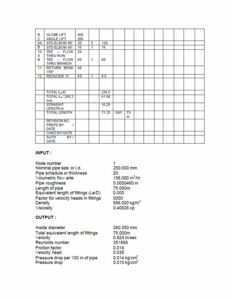
HOW TO CALCULATE NPSH AVAILABLE:
The following parameters shall be considered when calculating NPSH.
a. Vapour pressure
b. Static head
c. Friction .
d. Strainer drop
e. Suction pressure

The empirical formula to calculate NPSH is
1. Assume some line configuration to get total equivalent lengths and convert that
in to friction drop.


LS1 –LS2 LEVEL HIGH ALARM
LS3-LS4 LEVEL LOW ALARM
LS5-LS6 LEVEL LOW ALARM & TRIP OF PUMP
LEVEL SWITCH IS OF DISPLALER TYPE.
SETTING IS 70 MM BELOW THE LEVEL.