Centrifugal Pumps Sterling Cap_5
7
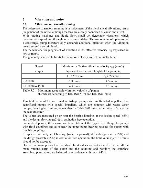
171 5 Vibration and noise 5.1 Vibration and smooth running The reference to smooth running, is a judgement of the mechanical vibrations, less a judgement of the noise, although the two are closely connected as cause and effect. With rotating machines and liquid flow, small yet detectable vibrations, which increase with speed and throughput, are unavoidable. The smoothness of operation of a centrifugal pump therefore only demands additional attention when the vibration levels exceed a certain level. The benchmark for judgement of vibration is its effective velocity v eff expressed in m/s or mm/s. The generally acceptable limits for vibration velocity are set out in Table 5.01 Speed n rpm Maximum effective vibration velocity v eff (mm/s) dependent on the shaft height of the pump h 1 h 1 < 225 mm h 1 > 225 mm n < 1800 2.8 mm/s 4.5 mm/s n > 1800 to 4500 4.5 mm/s 7.1 mm/s Table 5.01 Maximum acceptable vibration velocity of pumps (Limits set according to DIN ISO 5199 and DIN ISO 9905) This table is valid for horizontal centrifugal pumps with multibladed impellers. For centrifugal pumps with special impellers, which are common with waste water pumps, then higher limiting values than in Table 5.01 may be permitted if stated by the manufacturer. The values are measured on or near the bearing housing, at the design speed ( 5%) and the design flowrate ( 5%) in cavitation free operation. For vertical pumps, the measurements are taken at the upper drive flange for pumps with rigid couplings and at or near the upper pump bearing housing for pumps with flexible couplings. Irrespective of the type of bearing, (roller or journal), at the design speed ( 5%) and the design flowrate ( 5%) in cavitation free operation, the limit value v eff = 7.1 mm/s should not be exceeded. One of the assumptions that the above limit values are not exceeded is that all the main rotating parts of the pump and the coupling and possibly the complete assembled pump rotor, are balanced in accordance with ISO 1940-1.
-
Upload
cuervohijoguacho -
Category
Documents
-
view
108 -
download
2
Transcript of Centrifugal Pumps Sterling Cap_5
171
5 Vibration and noise5.1 Vibration and smooth running The reference to smooth running, is a judgement of the mechanical vibrations, less a judgement of the noise, although the two are closely connected as cause and effect. With rotating machines and liquid flow, small yet detectable vibrations, which increase with speed and throughput, are unavoidable. The smoothness of operation of a centrifugal pump therefore only demands additional attention when the vibration levels exceed a certain level. The benchmark for judgement of vibration is its effective velocity veff expressed in m/s or mm/s. The generally acceptable limits for vibration velocity are set out in Table 5.01
Speedn rpm
Maximum effective vibration velocity veff (mm/s) dependent on the shaft height of the pump h1
h1 < 225 mm h1 > 225 mm
n < 1800 2.8 mm/s 4.5 mm/s n > 1800 to 4500 4.5 mm/s 7.1 mm/s Table 5.01 Maximum acceptable vibration velocity of pumps (Limits set according to DIN ISO 5199 and DIN ISO 9905)
This table is valid for horizontal centrifugal pumps with multibladed impellers. For centrifugal pumps with special impellers, which are common with waste water pumps, then higher limiting values than in Table 5.01 may be permitted if stated by the manufacturer. The values are measured on or near the bearing housing, at the design speed ( 5%)and the design flowrate ( 5%) in cavitation free operation. For vertical pumps, the measurements are taken at the upper drive flange for pumps with rigid couplings and at or near the upper pump bearing housing for pumps with flexible couplings. Irrespective of the type of bearing, (roller or journal), at the design speed ( 5%) and the design flowrate ( 5%) in cavitation free operation, the limit value veff = 7.1 mm/s should not be exceeded. One of the assumptions that the above limit values are not exceeded is that all the main rotating parts of the pump and the coupling and possibly the complete assembled pump rotor, are balanced in accordance with ISO 1940-1.
© Sterling Fluid Systems B.V

172
The smooth running of a centrifugal pump which was acceptable during commissioning, can deteriorate during operation due to imbalance resulting from:
asymmetric build up of deposits
asymmetric corrosion
asymmetric erosion due to abrasive solids in the pumped liquid
asymmetric material loss due to cavitation
foreign body jammed in impeller
damage to one or more impeller blades
Other factors which can influence the smooth running of the pump can include an increase in bearing play or clearances or incorrect assembly after repair or inspection. Excessive forces transmitted from the pipework can also impact on smooth running.
5.2 Noise 5.2.1 General concepts SoundPressure oscillations in the air are denoted by sound. Human hearing can detect air vibrations and pressure waves in the range 16 to 16000 Hz. Infrasound below 16 Hz and ultrasound above 16000 Hz are outside the audible range. As well as in air and other gases, sound waves can be propagated in solids and liquids. Sound transmitted through solids or liquids cannot be detected by the human ear unless they are transformed into airborne sound. In the following discussions therefore sound refers to airborne sound.
Tone, timbre, noiseDepending on the source of the noise, the pressure oscillations manifest themselves in various ways described as :
Tone: a sinusoidal (single) frequency within the audible range Timbre: a mixture of basic and higher frequencies which have a simple numerical
relationship to each other. Noise: a term for multiple frequency sound, often simply used for machinery
derived sound.
© Sterling Fluid Systems B.V

173
Sound pressure, sound pressure levelThe sound pressure p is the oscillating pressure which is superimposed on the atmospheric pressure as a result of the sound oscillations. For the measurement of sound pressure level L, the logarithmic ratio of the sound pressure p to a reference level po has been established;
pLp = 20 · lg —— in dB p0
with p in µbar and p0 = 2 · 10– 4 µbar (reference sound pressure) The value of sound pressure is non-dimensional, but in honour of the inventor of the first functional telephone, Graham Bell, it is quoted in the unit of Bel, or the more manageable deciBel (dB).
Weighted sound pressure levelIn order to relate sound measurements to the actual audible sensitivity of the ear, the sound pressures at low and high frequencies are differently weighted by the incorporation of filters in the measuring instrument. These weighted sound pressure levels are designated A, B, C & D to denote the filter used and expressed with the units dB(A), dB(B), dB(C) & dB(D) respectively. The standardised weighted curve A (filter characteristic), roughly takes account of the ears sensitivity for moderate engineering noise and therefore dB(A) is the weighting which should be used for evaluation of noise in the workplace.
Sound power, sound power levelThe sound power W (unit Watt) is the quotient of the emitted sound energy and associated duration and proportional to the square of the sound pressure. The sound power level is given by:
WLw = 10 · lg—— in dB W0
with W in Watt and W0 = 10– 12 W (reference sound power)
5.2.2 Sound (noise) measurement, unitsThe procedures for measuring sound are defined in standards such as EN 12639. The sound pressure level is measured by a sound pressure meter on a hypothetical measurement surface S. This surface follows the actual surface of the machine at a distance of 1m, normally in the simple geometric form of a rectangular geometric solid whose six faces are parallelograms. The A-sound pressure level is averaged over the measuring surface S and if necessary corrected for the influence of background noise and reflections is referred to as the sound pressure level LpA and expressed in dB(A).As a measure of the noise emitted by the machine to the surrounding air, under defined positional conditions, the A-weighted sound power level LwA is used. It can be determined from the sum of the sound pressure level at the measurement surface LpA and the value of LS for the measurement surface:
© Sterling Fluid Systems B.V

174
SLwA = LpA + LS in dB(A) where LS = 10 · lg—— in dB S0
S = measurement area in m² and S0 = 1 m² (reference area). For similar types of machines, where the measurement surface value does not differ by more than 1 dB, it is usually sufficient to compare the sound pressure level at the surface directly. For machines where the sound pressure level at the measurement surface has been determined for which the measurement surface value differs by more than 1 dB, the A-sound power level should be used for comparison. For more accurate investigations, a sound level measurement covering the entire frequency range is inadequate. The range must be subdivided into individual sound bands, as only by this method can clear conclusions be drawn as to the source of the sound and the appropriate measure to reduce it. For such sound analyses, filters are used which only allow the passage of a defined band. The entire range of frequencies is divided into octaves and the sound pressure level is noted for each mid point frequency. These mid point frequencies have the following series: 63 Hz - 125 Hz - 250 Hz - 500 Hz - 1000 Hz - 2000 Hz - 4000 Hz - 8000 Hz
5.2.3 Noise emissions of centrifugal pumpsIn centrifugal pumps, mechanical energy is transferred to the pumped liquid through the shaft and impellers, resulting in periodic pressure oscillations. This is because the number of impeller and guide vanes is finite and is due to turbulent flow, friction and vortex shedding from boundary layers. The pump casing and attached pipework are excited by these oscillations, which are transmitted to the surrounding air and manifested as noise. A particularly distinctive noise is generated if the required (NPSHR) value of the pump is not achieved and cavitation ensues, (see section 1.6). The unit of measurement for the noise generated by a pump and emitted to the environment is the A-weighted sound pressure level LWA in Decibel, dB(A). Investigation and measurements of the sound pressure levels emitted by the vast range of centrifugal pumps, shows that it is primarily dependent on the design and power absorbed. For a few selected designs, within a specific performance range, the expected A-weighted sound pressure level can be calculated from the following formula.
© Sterling Fluid Systems B.V
175
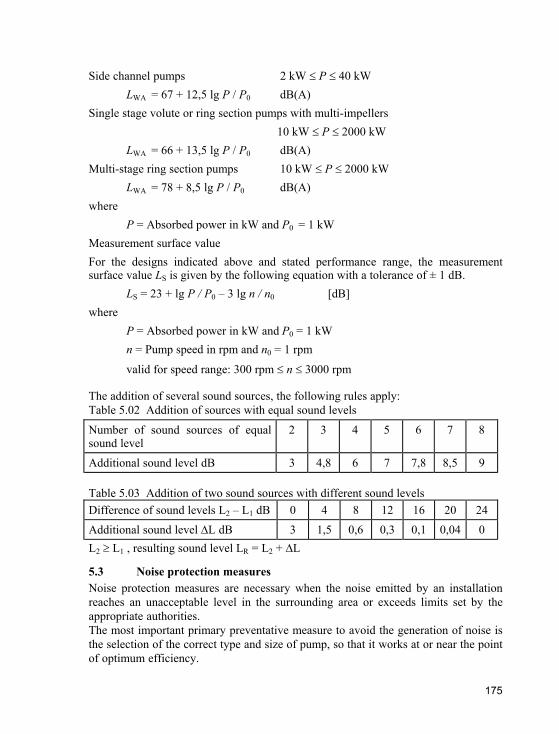
Side channel pumps 2 kW P 40 kW LWA = 67 + 12,5 lg P / P0 dB(A)
Single stage volute or ring section pumps with multi-impellers 10 kW P 2000 kW
LWA = 66 + 13,5 lg P / P0 dB(A) Multi-stage ring section pumps 10 kW P 2000 kW
LWA = 78 + 8,5 lg P / P0 dB(A) where
P = Absorbed power in kW and P0 = 1 kW Measurement surface value For the designs indicated above and stated performance range, the measurement surface value LS is given by the following equation with a tolerance of ± 1 dB.
LS = 23 + lg P / P0 – 3 lg n / n0 [dB] where
P = Absorbed power in kW and P0 = 1 kW n = Pump speed in rpm and n0 = 1 rpm
valid for speed range: 300 rpm n 3000 rpm
The addition of several sound sources, the following rules apply: Table 5.02 Addition of sources with equal sound levels
Number of sound sources of equal sound level
2 3 4 5 6 7 8
Additional sound level dB 3 4,8 6 7 7,8 8,5 9
Table 5.03 Addition of two sound sources with different sound levels Difference of sound levels L2 – L1 dB 0 4 8 12 16 20 24 Additional sound level L dB 3 1,5 0,6 0,3 0,1 0,04 0 L2 L1 , resulting sound level LR = L2 + L
5.3 Noise protection measures Noise protection measures are necessary when the noise emitted by an installation reaches an unacceptable level in the surrounding area or exceeds limits set by the appropriate authorities. The most important primary preventative measure to avoid the generation of noise is the selection of the correct type and size of pump, so that it works at or near the point of optimum efficiency.
© Sterling Fluid Systems B.V
176
This presupposes that the HAQ characteristics of the system have been determined as accurately as possible. Excessive safety factors lead to the selection of an unnecessarily oversized pump, which therefore operates under partial load condition, resulting in higher noise levels. Further primary measures to minimise the flow noise and thus the mechanical resonance include the following:
Avoid operation in the region of cavitationSelecting a low pump speed Selection giving low flow velocities in the connecting pipework Use of low noise fittings Locating fittings at a distance from the pump flanges Avoiding sudden changes in cross section of the pipework Use of long radius bends Careful alignment of pump, motor and coupling Mounting the baseplate on vibration dampers Connecting pipework to the pump with flexible bellows Use of vibration reducing pipework mountings and bushes when passing through walls etc.
Noise reduction is also achieved by the use of low noise motors, which have unidirectional cooling fans. If a gearbox drive is necessary, then this should also be of a low noise construction. If satisfactory results are not obtained by the above measures, or the sound level is basically too high because of the design and absorbed power of the pump, then secondary measures must be adopted. This means the use of insulation and silencing materials. A distinction is drawn between active measures to reduce the noise emission at source (sound reduction) and passive measures to reduce the effect on people working in the area (personnel protection). Active measures in the main, comprise of sound reflecting or sound absorbing walls or complete enclosures. If maintenance access is required during operation, then the enclosure will be fitted with lockable service hatches or access doors. Passive measures include the provision of sound proofed cabins and control rooms or ear protection.
© Sterling Fluid Systems B.V
177
To obtain the best sound reduction, it is necessary to have a sound / frequency analysis to decide on the most suitable protection measures to adopt.
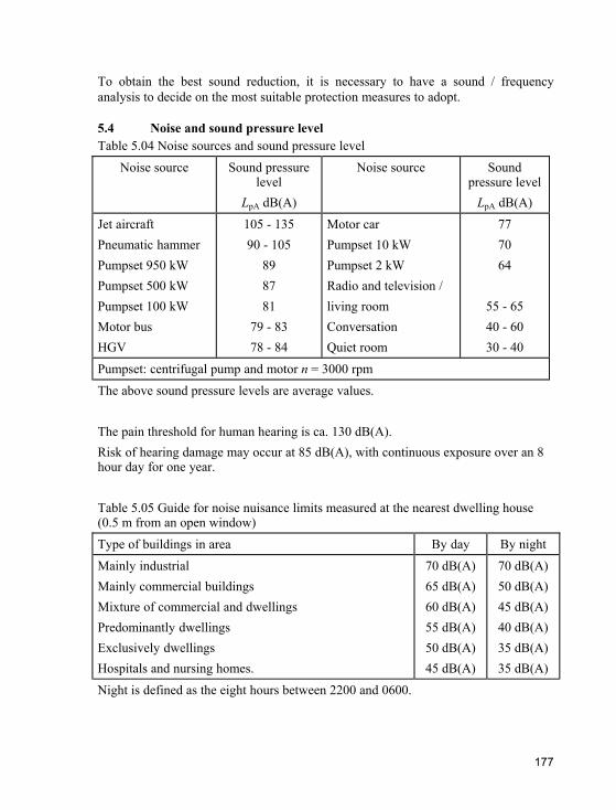
5.4 Noise and sound pressure levelTable 5.04 Noise sources and sound pressure level
Noise source Sound pressure level
LpA dB(A)
Noise source Sound pressure level
LpA dB(A) Jet aircraft Pneumatic hammer Pumpset 950 kW Pumpset 500 kW Pumpset 100 kW Motor bus HGV
105 - 135 90 - 105
898781
79 - 83 78 - 84
Motor car Pumpset 10 kW Pumpset 2 kW Radio and television / living room Conversation Quiet room
777064
55 - 65 40 - 60 30 - 40
Pumpset: centrifugal pump and motor n = 3000 rpm The above sound pressure levels are average values.
The pain threshold for human hearing is ca. 130 dB(A). Risk of hearing damage may occur at 85 dB(A), with continuous exposure over an 8 hour day for one year.
Table 5.05 Guide for noise nuisance limits measured at the nearest dwelling house (0.5 m from an open window) Type of buildings in area By day By night Mainly industrial Mainly commercial buildings Mixture of commercial and dwellings Predominantly dwellings Exclusively dwellings Hospitals and nursing homes.
70 dB(A) 65 dB(A) 60 dB(A) 55 dB(A) 50 dB(A) 45 dB(A)
70 dB(A) 50 dB(A) 45 dB(A) 40 dB(A) 35 dB(A) 35 dB(A)
Night is defined as the eight hours between 2200 and 0600.
© Sterling Fluid Systems B.V