CENTRIFUGAL PUMPS -...
34
CENTRIFUGAL PUMPS LIST OF TROUBLES Page No . 1. Pump not starting. 1 2. No liquid delivered. 2 3. Not enough liquid delivered. 3 4. Pump discharge pressure is low. 5 5. Pump looses prime after starting. 6 6. Pump overloads driver. 7 7. Excessive vibration. 8 8. Bearing overheat. 9 9. Bearing wears rapidly. 11 10. Text paras. 12
Transcript of CENTRIFUGAL PUMPS -...

CENTRIFUGAL PUMPS
LIST OF TROUBLES Page No. 1. Pump not starting. 1
2. No liquid delivered. 2
3. Not enough liquid delivered. 3
4. Pump discharge pressure is low. 5
5. Pump looses prime after starting. 6
6. Pump overloads driver. 7
7. Excessive vibration. 8
8. Bearing overheat. 9
9. Bearing wears rapidly. 11
10. Text paras. 12

CAMTECH
Maintenance Instructions Series for Centrifugal Pumps. Ver. 1.0
1
TROUBLE 1 : PUMP DOES NOT START
Is N motor Y running.
Is
3 Ph. supply Y Is N
available at motor coupling
terminals. OK
Y
N
Is
impeller rotation N
Ok.
Y
Chart No. 1
Check the induction motor control panel/ TPI switch & cable & fuses.
Check for pump motor coupling.
Coupling defective.
Check for impeller rotation.
Motor is defective.
Impeller defective.
Power supply not available.
Contact your foreman.
Check for running of driving motor.

CAMTECH
Maintenance Instructions Series for Centrifugal Pumps. Ver. 1.0
2
Check for the speed.
Prime the pump manually. Refer text para 1.
Refer text para 3.
Refer text para 6.1 on plugging of Impeller.
TROUBLE 2 : NO WATER DELIVERED.
Check for pump prime It may be lack of prime Y Is N Priming OK Check Y Is N whether Y speed low . sluice valve closed. N Check with gauges normal N Is Y suction should not discharge head exceed 15 ft. or 4.5 m. too high Is Y suction N lift too high N Is N Is Y dis impeller plugged Y Is N rotation wrong
Chart No. 2
Check for sucti- on. It may be too high.
Check for impeller rotation,it may be in wrong direction.
Refer text para 5 on suction head.
Check pipe / impeller for plugging.
Contact your electrical foreman.
Check valtage & Refer text para 2
Open sluice valve.
Inspect piping suction strainer and impeller.
Refer text para 4.

CAMTECH
Maintenance Instructions Series for Centrifugal Pumps. Ver. 1.0
3
TROUBLE 3 : NOT ENOUGH WATER BEING DELIVERED
Is
N Air Y leakage present
Is Y Speed N Y too low
Is N discharge Y head too high. Is Y suction N lift too high. Is N there Y any plugging
Chart No. 3
Check for air leak in suction line or stuffing box.
Refer text para 7 on air leakage.
Check for speed, it may be low.
Check for sluice valve, it may be closed.
Refer taxt para 5 on suction head.
Check for plugging of pmpeller or suction line.
Refer taxt para 6.1 on plugging.
Check for impeller damage or worn.
Check voltage. Refer para 2.
Open the sluice valve.
Check for suction lift. It may be too high.
Check with gauges. Normal suction should not exceed 15 ft. or 4.5 m.
Refer text para 3 on discharge head.
CAMTECH
Maintenance Instructions Series for Centrifugal Pumps. Ver. 1.0
4
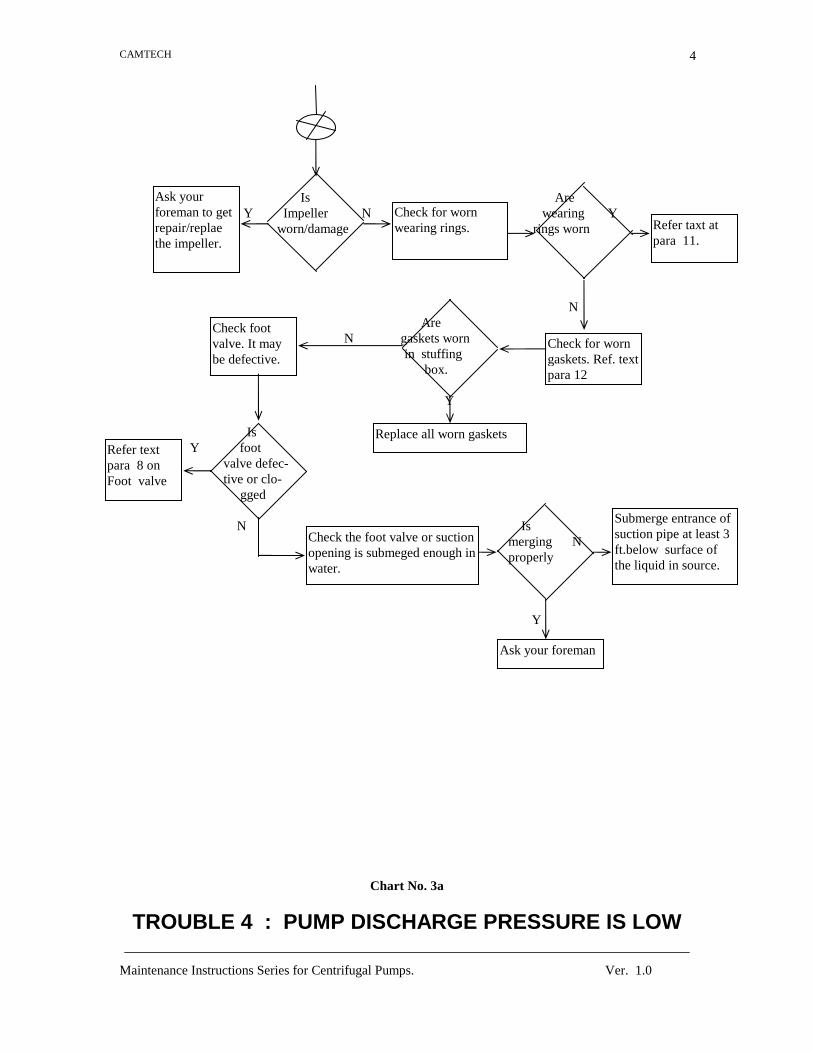
Is Are Y Impeller N wearing Y worn/damage rings worn N Are N gaskets worn in stuffing box. Y Is Y foot valve defec- tive or clo- gged N Is merging N properly Y
Chart No. 3a
TROUBLE 4 : PUMP DISCHARGE PRESSURE IS LOW
Check for worn wearing rings. Refer taxt at
para 11.
Check for worn gaskets. Ref. text para 12
Refer text para 8 on Foot valve
Replace all worn gaskets
Check the foot valve or suction opening is submeged enough in water.
Submerge entrance of suction pipe at least 3 ft.below surface of the liquid in source.
Ask your foreman
Ask your foreman to get repair/replae the impeller.
Check foot valve. It may be defective.

CAMTECH
Maintenance Instructions Series for Centrifugal Pumps. Ver. 1.0
5
Is gauge Y defective N Is gas/air Y present in the suction N Is N there Y any obstruction in the pipe Is impeller Y damage N
Chart No. 4
Check for gas or air in liquid. Ref. text para 5.1
Remove the gas/ air present in pipe. Ref. para 5.1.
Check for water obstruction in suction pipe.
Clear the obstruction in the pipe.
Check for the impeller damaged. Ref. para 6.
Replace the impeller.
Contact your electrical foreman
Discharge pressure reading is too low.
Repair/replace gauge.

CAMTECH
Maintenance Instructions Series for Centrifugal Pumps. Ver. 1.0
6
TROUBLE 5 : PUMP LOOSES PRIME AFTER STARTING
Is Y priming N OK. Is there any N Are Y leakage there air/gas of air pockets Y N Is suction head Y too high N Is Y inlet suff- N iciently sub- merged
Chart No. 5
Check for imcomplete priming. Ref. para .1.
Check for air leakages. Ref para 7.
Complete priming in proper manner. Ref. text para 1.
Check for air or gas pockets in pipe.
Remove/reduce the air pockets. .
Arrest the leakage. Ref. para 7. Check for suction
head. Ref. text para 5.
Reduce the suction head.
Submerge the pipe inlet suffciently.
Contact your Electrical foreman.

CAMTECH
Maintenance Instructions Series for Centrifugal Pumps. Ver. 1.0
7
TROUBLE 6 : PUMP OVERLOADS THE DRIVER If N discharge Y head is too low. Is Y pump speed too low. N Is packing too Y tight. N Is Y shaft bent. N Is Y casing distorted N Is there any Y misalignment . N
Chart No. 6
Check for low discharge head
Make proper discharge head according to text para 3.
Check for pump speed.
Check for distorted casing.
Repair/replace the casing. Ref. text para 15.
Check for misalignment
Make proper tightening of the packing. Ref. 12.
Make proper alignment of pump. Ref. text para 16.
Check for packing. Ref. text para 12
Check for bent shaft.
Ask your electrical foreman.
Repair/replace the bent shaft. Ref. text para 14.
Check voltages. Ref. text para 2.

CAMTECH
Maintenance Instructions Series for Centrifugal Pumps. Ver. 1.0
8
Check the foundation of pump for vibration
TROUBLE 7 : EXCESSIVE VIBATION OF PUMP
Is foundation N of pump vibrating Y Is Y gas or air present in the pipe N Is Y beaing worn or loose. N Is position N of control valve proper Y Is Y rotor shaft bent. N Is rotor Y unbalance N
Chart No. 7
Make proper and rigid foundation. Ref text para 13.
Check for air in liquid. Ref text para 5.1
Remove the air/gas in the pipe.
Repair/replace the bearings.
Check for position of control valve in discharge.
Position the control valve in proper way.
Check for shaft bending. Ref text para 14.
Repair /replace the rotor shaft. Ref para 14.
Balance the rotor.
Check for rotor unbalancing.
Contact your Electrical foreman.
Check the slack or loose bearings. Ref text para 10.
CAMTECH
Maintenance Instructions Series for Centrifugal Pumps. Ver. 1.0
9
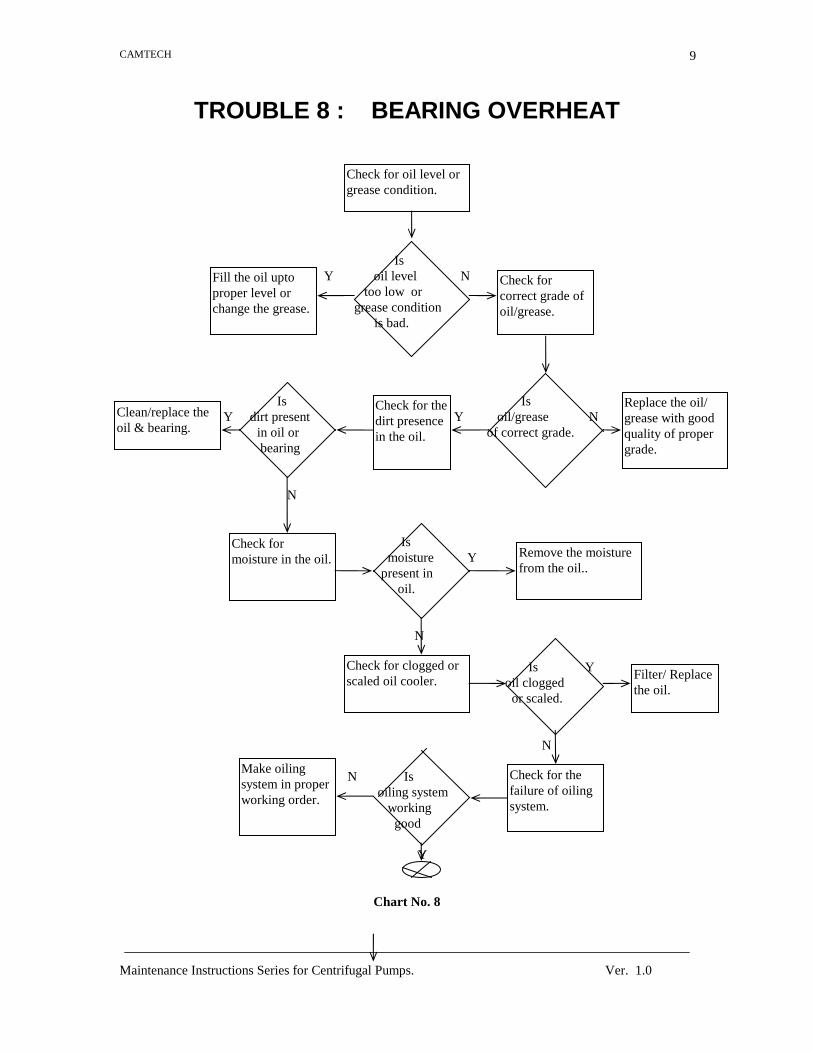
TROUBLE 8 : BEARING OVERHEAT Is Y oil level N too low or grease condition is bad. Is Is Y dirt present Y oil/grease N in oil or of correct grade. bearing N Is moisture Y present in oil. N Is Y oil clogged or scaled. N N Is oiling system working good Y
Chart No. 8
Check for oil level or grease condition.
Check for correct grade of oil/grease.
Check for the dirt presence in the oil.
Fill the oil upto proper level or change the grease.
Clean/replace the oil & bearing.
Replace the oil/ grease with good quality of proper grade.
Check for moisture in the oil. Remove the moisture
from the oil..
Check for clogged or scaled oil cooler.
Filter/ Replace the oil.
Check for the failure of oiling system.
Make oiling system in proper working order.

CAMTECH
Maintenance Instructions Series for Centrifugal Pumps. Ver. 1.0
10
Is bearing N cooling water enough Y Is Y bearing too tight. N Is oil seal Y fitted too closely on the shaft N
Chart No. 8a
TROUBLE 9 : BEARING WEAR RAPIDLY
Check for not enough cooling water.
Make arrangement for enough cooling water.
Checking for tightness of the bearing.
Tight the bearing properly.
Check for oil seal fitting.
Make proper fitting of the oil seal on shaft.
Ask your foreman.

CAMTECH
Maintenance Instructions Series for Centrifugal Pumps. Ver. 1.0
11
Is Is pump Y rotor shaft Y alingment N bent. proper. N Is Is their N excessive Y any vibration. thrust from inside pump Y N Is Is Y dirt N lack Y present in of lubrication bearing. there. N Is N bearing Y cooling is excess
Chart No. 9
TEXT-PARAS
Check for alignment. Ref para 16
Make proper alignment. Ref para 16.
Check for bent shaft. Ref para 14
Repair/ replace the rotor shaft. Ref para 14
Check for excessive cooling of the bearing.
Check for vibration. Ref text para 13.
Reduce the cooling of bearing.
Check for excessive thrust.
Ask your electrical foreman.
Reduce the thrust of mechanical failure.
Clear the vibratation. Ref para 13.
Check for lack of lubrication. Ref para 10.
Lubricate the bearing ref para 10
Check for dirt in bearing. Ref para 10d
Clean /replace the bearing. Ref pra 10 d.
CAMTECH
Maintenance Instructions Series for Centrifugal Pumps. Ver. 1.0
12
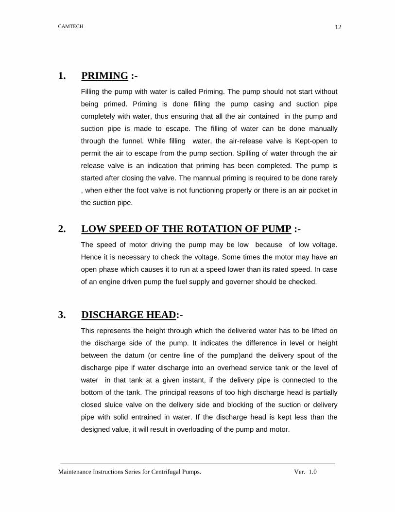
1. PRIMING :-
Filling the pump with water is called Priming. The pump should not start without
being primed. Priming is done filling the pump casing and suction pipe
completely with water, thus ensuring that all the air contained in the pump and
suction pipe is made to escape. The filling of water can be done manually
through the funnel. While filling water, the air-release valve is Kept-open to
permit the air to escape from the pump section. Spilling of water through the air
release valve is an indication that priming has been completed. The pump is
started after closing the valve. The mannual priming is required to be done rarely
, when either the foot valve is not functioning properly or there is an air pocket in
the suction pipe.
2. LOW SPEED OF THE ROTATION OF PUMP :-
The speed of motor driving the pump may be low because of low voltage.
Hence it is necessary to check the voltage. Some times the motor may have an
open phase which causes it to run at a speed lower than its rated speed. In case
of an engine driven pump the fuel supply and governer should be checked.
3. DISCHARGE HEAD:-
This represents the height through which the delivered water has to be lifted on
the discharge side of the pump. It indicates the difference in level or height
between the datum (or centre line of the pump)and the delivery spout of the
discharge pipe if water discharge into an overhead service tank or the level of
water in that tank at a given instant, if the delivery pipe is connected to the
bottom of the tank. The principal reasons of too high discharge head is partially
closed sluice valve on the delivery side and blocking of the suction or delivery
pipe with solid entrained in water. If the discharge head is kept less than the
designed value, it will result in overloading of the pump and motor.

CAMTECH
Maintenance Instructions Series for Centrifugal Pumps. Ver. 1.0
13
4. DIRECTION OF ROTATION :-
The pump must be run in the direction indicated by an arrow on the casing which
is always toward the discharge nozzel. Rotation, right-hand or left hand, is
determined by facing the pump from the drive end. It is noted that the impeller
rotates in a direction away from the vane curvature.
5. SUCTION HEAD:-
Suction head represents the difference in level between the centre line of the
pump (also called datum or datum line) and the water level in the source. It
indicates the vertical height through which the water has to be lifted or sucked on
the suction side of the pump. The suction lift may be too high due to the clogging
of the pump inlet with mud, gravel or some other obstruction. The other reason
could be a broken disk or a clogged strainer of the foot valve. In case the pump
is being started for the first time, the actual suction lift could be execessive. In
such a case the pump is to be lowered so that the total suction lift is with in 6.5
meter ( preferably within 4.5m to ensure efficient operation)
5.1 VAPOUR LOCK IN SUCTION LINE :-
Vapour pockets may develop in the pump suction line due to excessive suction
head and inadequate submergence of the foot valve. The possible remedies
include lowering the pump and increasing the submergence of the foot valve
below the pumping water level.
6. IMPELLER:-
Impeller is the rotary element of the pump. It is a wheel or discmounted on the
shaft and provided with a number of vanes are arranged in a circular array
around an inlet opening at the centre. The impeller is secured on a shaft
mounted on suitable bearings. The design of the impeller greatly influences the
efficiency and operating characteristics of centrifugal pump.
6.1 PLUGGING OF IMPELLER :-

CAMTECH
Maintenance Instructions Series for Centrifugal Pumps. Ver. 1.0
14
In case of cavity wells, solids in the water may get a accumulated in the impeller.
This may block the pump either completely or partially. Under such situation, the
pump casing should be opened and all the parts of the impeller cleaned
periodically.
6.2 IMPELLER EYE TOO SMALL :-
The capacity of a pump is a function of diameter of the impeller eye. Therefore,
incorrect choice of a pump or moving it from one base to the other may result in
this trouble. The only remedy in such a case replacement of the pump with a
properly selected one.
7. AIR LEAKAGE :-
Air leakage may take place either in the stuffing box or in the suction pipe. The
stuffing box should leak a small amount of water during pump operation. First of
all, one should check for the desired leakage by making suitable adjustments. If
this adjustments fails to give the desired results, the pump should be stopped
and the gland packing checked for damage. A damaged gland packing should be
replaced by a new one. The leakage from the stuffing box is again checked. If
even after replacement of the gland packing, the defect is not removed, the
suction line will have to be checked for air leakage. The flanges and screwed
joints are tightened first. In case the leakage is not traceable the same can be
located by using a flame or a lighted match stick. The flame if held close to the
pipe and flanges, will be drawn towards any leak.

CAMTECH
Maintenance Instructions Series for Centrifugal Pumps. Ver. 1.0
15
8. FOOT VALVE :-
Foot valve is an integral component of a centrifugal pump. It is fixed at the
bottom of the suction pipe. It keeps the centrifugal pump primed and restricts the
entry of foreign matter, specially floating debris and aquatic plants into the
suction pipe. The valve is a one way flap piece made of leather or rubber and
hinged to the valve body. When the pump is not working the valve rests on a well
machine base plate and prevents the return flow of water to the well or other
source. Thus water is retained in the pump casing and suction pipe. The total
area of the opening in the strainer of the footvalve should be about 2.5 times the
cross sectional area of the suction pipe. Any reduction in the open area results in
heavy friction losses and reduced pump discharge. Similarly, the flap valve in the
valve body should open fully.
9. SLUICE VALVE :-
If sluice valve is provided, it is kept closed at the time of starting. This will allow
the motor to be started without load. When the pump reaches its full speed, the
sluice valve is opened gradually until the desired quantity of water is delivered.
Care is taken not to run the pump for a long period with the sluice valve closed,
as this may over heat the pump.
10. BEARING:-
(a) Grease lubrication:-
For grease lubricated ball bearing, only a small amount of lubricant is required
and lubrication intervals are generally long. How long a bearing can run without
grease being added or replaced, depends upon the grease properties, the size
and design of the bearing and housing, the speed and other operating
conditions. For pumps operating under severe service, perhaps greasing is
required every three months and for normal service 1 year to be on the safe side,
the addition of grease should be determined from experience.

CAMTECH
Maintenance Instructions Series for Centrifugal Pumps. Ver. 1.0
16
(b) Oil lubrication :-
For oil-lubricated ball bearings mineral oil of the best quality should be used.
Bearing housing with oil-bath lubrication or with an oil sump which is to be filled
to a given level, ordinarily are equipped with oil gauges. Oil is added when the oil
level due to loss, has dropped below the established low limit. In general, the oil
level should never reach higher than centre of the lowest rolling element when
the bearing is not rotating.
(c) Heating of bearing :-
Heating of bearing invariably means too much grease. Careful inspection to
determine the trouble should be made before more grease is added.
(d) Cleaning of bearing:-
Great care should be exercised to keep the bearing housing immaculately clean,
and only clean grease should be used. Under no circumstances should grease
which has been used before be applied. Foreign solids or liquids invading the
housing can completely ruin the bearings in a short time. It is important to use
clean instruments and clothes when cleaning housing. The housing should be
flushed clean, using gasoline or a high grade of water free kerosene.
11. WEARING RINGS :-
Wearing ring clearances should be checked from time to time. When the wearing
ring clearance is increased, a loss in capacity and head is caused . If the
clearance is approximately twice the original, or if the loss in capacity and head
does not meet requirements, it is time to replace the rings.
12. STUFFING BOX AND SHAFT PACKINGS :-
Stuffing box should be carefully cleaned and the packing placed in them.
Generally a leakage of 15-30 drops of liquid per minute from the stuffing box is
excessive or the packing is worn, the entire packing in the box will have to be
replaced. Replacing just a ring or two will not result in an effective sealing. The
shaft and shaft sleeve surface are properly cleaned before inserting the packing

CAMTECH
Maintenance Instructions Series for Centrifugal Pumps. Ver. 1.0
17
rings. There should not be any burrs or scores on the working surface. If the
shaft sleeve is badly worn or scored, it is replaced.
The radial clearance between the shaft and the stuffing box is measured
for determining the size of a new gland packing to be provided.
Be sure that sufficient packing is placed at the back of the water seal
cage. If the water is to be pumped is dirty or gritty, sealing water should be piped
to the stuffing box from clean outside source of supply in order to prevent
damage to the packing and shaft. In placing the packing each packing ring
should be cut to the proper length so that end comes together but do not overlap.
The succeding rings of packing should be placed in the stuffing box having
packing joints staggered. The packing should not be pressed too tight as it may
result in burning the packing and cutting the shaft. If the stuffing is not properly
packed, friction in stuffing box prevents turning the rotor by hand. On starting the
pump it is advised to have the packing slightly loose without causing an air leak,
and if it seems to leak, instead of putting too much pressure initially tightened
up the gland gradually. The packing should be occassionally changed.
13. Pump Foundation :-
The foundation should be sufficiently substantial to absorb any vibration and to
form a permanent rigid support for the base plate. This is important for
maintaining the alignment of a direct connected unit. A concrete fondation on a
solid base is advisable . Foundation bolts of the proper size should be embedded
in the concrete located by a drawing or emplate. Apipe sleeve of about two and
one half diameter larger than the bolts should be used to allow movement for the
final position of the foundation bolts.

CAMTECH
Maintenance Instructions Series for Centrifugal Pumps. Ver. 1.0
18
14. BENT SHAFT :-
Thermal distoration, damage during pump overhaul or wrong assembly of the
rotating assembly can cause the bent shaft. Check the shaft deflection by means
of a dial gauge by turning the shaft between lathe centres.
The average run out of the shaft should not be more than 0.075 mm and
0.150 mm for high speed and low speed pumps respectively. The shaft deflection
should be checked with a dial gauge by turning the shaft between the lathe
centres. If the shaft is found damaged it should be replaced.
15 DISTORTED CASING :-
Many a time, the casing gets distorted because of poorly aligned suction and
discharge piping. This results in excessive friction between the impeller and
casing. The piping and the alignment of the primemover should be checked. The
wearing rings should also be checked and replaced, if found damaged.
16. PUMP ALIGNMENT :-
The alignment of the shaft is one of the important considerations. Realignment of
pump is necessary after complete unit has been levelled on the foundation and
again after the grout has been set and foundation both has been tightened. The
alignment must be checked after the unit is piped up and rechecked periodically.
Type of misalignment
(a) Angular misalignment:-
Shaft with axis concentric but not parallel.
(b) Parallel misalignment:-
Shaft with axis parallel but not conentric.
The two halves of the coupling should be at least 4 mm apart so that they
cannot touch each other when the driver shaft is rotated. Necessary tools for
approximately checking are a straight edge and an out side caliper.

CAMTECH
Maintenance Instructions Series for Centrifugal Pumps. Ver. 1.0
19
A check for parallel alignment is made by placing a straight edge across
both coupling periphery at the top, bottom and both the sides. The unit will be in
parallel alignment when the straight edge rests evenly on the coupling periphery
at all positions Care must be taken to have the straight edge parallel to the axis
of the shafts.
A check for angular misalignment is made by using an out side caliper
across the width of the coupling faces at various points.

CAMTECH
Maintenance Instructions Series for Centrifugal Pumps. Ver. 1.0
20
OPERATIONAL CHECKS FOR THE PUMPS
1. Checks for the pump before starting.
a) The shaft rotates freely.
b) The pump is primed.
c) If there is any valve in delivery branch, it is open.
d) The stuffing box (gland) is properly tightened (in case of gland packed
pump)
2. Checks during running conditions :
a) The direction of rotation is correct.
b) The pump is running smoothly.
c) See that the prime mover is not overloaded.
d) Leakage through stuffing box is normal i.e. 50 to 60 drops per minute
In the gland packing pump.
e) There is no leakage from mechanical seal.
f) The ball bearing do not get excessive hot.
g) Avoid idle running on operation against closed discharge valve for a
longer period of time.
CAMTECH
Maintenance Instructions Series for Centrifugal Pumps. Ver. 1.0
21
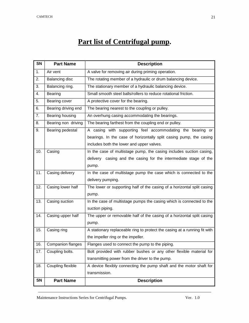
Part list of Centrifugal pump. SN Part Name Description
1. Air vent A valve for removing air during priming operation.
2. Balancing disc The rotating member of a hydraulic or drum balancing device.
3. Balancing ring. The stationary member of a hydraulic balancing device.
4. Bearing Small smooth steel balls/rollers to reduce rotational friction.
5. Bearing cover A protective cover for the bearing.
6. Bearing driving end The bearing nearest to the coupling or pulley.
7. Bearing housing An overhung casing accommodating the bearings.
8. Bearing non driving The bearing farthest from the coupling end or pulley.
9. Bearing pedestal A casing with supporting feel accommodating the bearing or
bearings. In the case of horizontally split casing pump, the casing
includes both the lower and upper valves.
10. Casing In the case of multistage pump, the casing includes suction casing,
delivery casing and the casing for the intermediate stage of the
pump.
11. Casing delivery In the case of multistage pump the case which is connected to the
delivery pumping.
12. Casing lower half The lower or supporting half of the casing of a horizontal split casing
pump.
13. Casing suction In the case of multistage pumps the casing which is connected to the
suction piping.
14. Casing upper half The upper or removable half of the casing of a horizontal split casing
pump.
15. Casing ring A stationary replaceable ring to protect the casing at a running fit with
the impeller ring or the impeller.
16. Companion flanges Flanges used to connect the pump to the piping.
17. Coupling bolts. Bolt provided with rubber bushes or any other flexible material for
transmitting power from the driver to the pump.
18. Coupling flexible A device flexibly connecting the pump shaft and the motor shaft for
transmission.
SN Part Name Description

CAMTECH
Maintenance Instructions Series for Centrifugal Pumps. Ver. 1.0
22
19. Coupling prime
mover
The half of the flexible coupling half, which is fitted on the prime
mover shaft.
20. Coupling pump half The half of the flexible coupling.
21. Deflector liquid A device to protect bearings by slinging off stuffing box leakage.
22. Diffuser A component adjacent to the impeller discharge which has multiple
passages of increasing area for converting velocity head into
pressure head.
23. Gasket A joining to provide leakage proof joint.
24. Gland A follower which comprises packing in a stuffing box.
25. Grease nipple A non return valve through which grease is pumped to the bearing.
26. Impeller A rotating element producing head.
27. Impeller enclosed An impeller having shrouds (walls) on both sides.
28. Impeller open An impeller without any shrouds.
29. Impeller semi open An impeller with a single shroud.
30. Impeller hub sleeve A replaceable, cylinder wearing part mounted on the extended pump
impeller hub.
31. Impeller key A parallel side piece used to prevent the impeller from rotating
relative to the shaft.
32. Impeller nut A threaded piece used to secure the impeller on the shaft usually
provided complete with locking device.
33. Impeller ring A replaceable ring fitted on the impeller shroud hub where it rotates in
the casing or casing ring.
34. Interstage bushing A replaceable bushing fitted into the stage through which the shaft or
shaft sleeve rotates.
35. Interstage
crossover
A specially designed piece that carries the flow from one stage to
another in a multistage pump.
36. Interstage
diaphragm
A removable stationary portion between stages of multistage pump.
37. Interstage sleeve A cylindrical piece mounted on the pump shaft between impellers of a
multistage pump.
38 Jack shaft An auxiliary shaft through which the pump shaft is driven.
39. Lantern ring Sealing liquid is supplied through the lantern ring into the stuffing box
to prevent air leakage into the pump.
40. Lubricator A device for applying lubricant to the point of use,
SN Part Name Description

CAMTECH
Maintenance Instructions Series for Centrifugal Pumps. Ver. 1.0
23
41. Mechanical seal
(rotating)
A flexible device mounted on the shaft in the stuffing box and lapped
rotating element sealing face held against stationary face.
42. Mechanical seal
(Stationary)
A sub assembly consisting of one or more parts mounted on the
stuffing stationary element box and having lapped sealing face.
43. Packing stuffing box A pliable lubricated material used to provide a seal around the portion
of the shaft located in the stuffing box.
44 Priming funnel A funnel used for priming the pump.
45. Priming funnel cock A valve to control liquid supply.
46. Pump bracket A casing in monosets accommodating pump on one side and motor
on the other.
47. Pump shaft A shaft which holds the rotating impeller and transmits the power.
48. Shaft sleeve A replaceable sleeve for protecting the shaft where it passes through
the stuffing box and stage bushing.
49 Shaft sleeve nut A threaded piece used to locate the shaft sleeve on the shaft.
50. Sleeve bearing A bush type bearing
51. Stuffing box A portion of the casing or cover through which the shaft extends and
in which the packing and gland or a mechanical seal is placed to
prevent leakage.
52 Stuffing box
bushing
A replaceable bushing fitted into the stuffing box throat through which
shaft or shaft sleeve rotates.
53. Suction cover A removable piece (with which the inlet nozzle may be integral) used
to enclose the suction side of the casing of an end suction pump.
54. Wear plate A replaceable plate against which the semi open impeller rotates.

CAMTECH
Maintenance Instructions Series for Centrifugal Pumps. Ver. 1.0
24
Maintenance schedule of Centrifugal pumps
1. Daily observations
a) Leakage through packing.
b) Bearing temperature
c) Whether any under noise or vibration is present and
d) Pressure, Voltage and current reading.
2. Half yearly attention
a) Free movement of the gland of the stuffing box
b) Cleaning and oiling of the gland bolts.
c) Inspection of packing and repacking , if necessary.
d) Alignment of the pump and the drive.
e) Cleaning of the oil lubricated bearings and replenishing fresh oil. If
bearings are grease lubricated, the condition of grease should be
checked and replaced to correct quantity, if necessary.
3. Annual attention
Complete overhaul, painting and output test.
Note : Never neglect maintenance just to adhere to arbitrary schedule. On
the other hand, do not perform unnecessary maintenance
operation because this defects the purpose of the routine
preventive programe.

CAMTECH
Maintenance Instructions Series for Centrifugal Pumps. Ver. 1.0
25
Daily observations
1. Leakage through packing : Water leak of 40 to 60 drops per minute is required for adequate cooling. If
leakage from the stuffing box is excessive or the packing is badly worn, replace
all the packings in the box. Never replace just one or two rings, they will not sent
effectively. Be certain to use only the grade of packing recommended by the
pump builder.
2. Bearing temperature : In general the temperature of any bearing in a centrifugal pump should not
exceed 160 °F. Before allowing a bearing to operate at any temperature above
the recommended, check with the pump manufacturer. Much depend on the type
of bearing, its lubricant and the duty of the bearing performs in the pump.
If any bearing is running hot, check for the cause. Ball or roller bearings
may be over lubricated. Remove some grease and test under load. Hot sleeve
bearing may not have enough oil, the oil rings may be stuck or broken, or the
lubricant may be too thick for its job. If the oil is thought to be too thick, change it.
Run the pump again. If the bearing still runs hot, dis-assemble, wash and inspect
the bearing. Replace bearing. Replace worn or damaged parts.
3. Any undue noise or vibration : If any undue noise or vibration present check for the cause and rectify, see the
trouble shooting charts.
4. Pressure, Voltage and current readings :

CAMTECH
Maintenance Instructions Series for Centrifugal Pumps. Ver. 1.0
26
Maintenance activities (overhaul) of the pump
Maintenance of rotating parts
1. Impeller : a) Removing of the impeller :
Before the impeller can be removed for inspection, scale and burrs must be
removed from the shaft with a file. To prevent the damage of the unbolting &
removing the case, use a screw driver to loosen the impeller set screw, clean the
shaft as the work progress.
If a bronze impeller is a shrink fit on the shaft, slip a metal sleeve over
shaft, while the impeller is heated. Start heating of the impeller with a torch from
the outside of the shroud, working towards the hub. Remove the impeller while
heating it, so its temperature will be equalise. When the impeller is loose pry it off
the shaft being carefull to press only against the shroud. Wear asbestos globes
when lifting the next impeller or use special lifting claims supplied by the pump
manufacturers.
b) Cleaning of impeller : If the impeller is dirty, clean it carefully before its inspection. Use a soft wire
brush or a steam lance to remove thick gummy residues. Scale, cock and other
deposits can be removed by chemical cleaning or sand blasting. In either case,
precautions must be taken to see that the impeller material is not damaged by
the cleaning methods chosen. Petting of the impeller may be caused by
condition, which can occur without audible noise.
c) Inspection : After removing the impeller from a pump inspect its eye, vanes, shrouds, wearing
rings, passages, hub and other parts. Wear may occur at the eye, vanes,
shrouds and other impeller parts. Corrosion, cavitation and erosion are generally
accompanied by a wasting away of the impeller or vane surfaces. Where the

CAMTECH
Maintenance Instructions Series for Centrifugal Pumps. Ver. 1.0
27
attack is severe, the thinned suction may have holes through them or may wrap
and defect.
d) Impeller Runout :
With pumps having bearings at each end of the shaft, mount the impellers,
wearing rings, spacer, and shaft sleeves on the shaft and support the assembly
between between centers. Set a dial gauge at zero and take readings at each
and at the centre of each shaft sleeve. Also take similar readings at each
impeller wearing ring. For most pumps, if the runout is not more than 0.0015 in.,
the assembly can be considered accurate and the shaft installed as is. If the
reading is greater, check for a bent shaft, out of square, dirty, or burred impeller
end of a shaft or spacer sleeve.
Check the runout on single-stage cantilevered-shaft pumps as shown in
fig. If the shaft binds or the dial gage shows a runout greater than 0.0015 in.,
loosen the ball bearing lock nut the check the runout again. If the impeller and
shaft assembly runs true, either the loc-nut washer is burred or the faces of it
and the bearing are not parallel. Smooth out the burrs, tighten the lock nut, and
check the runout. If there are no burrs, install a new washer and check the
runout.
If the assembly runs out more than 0.0015 in. after the lock nut is
loosened, dismantle and check for a bent shaft, cocked or loose ball bearing, or
out-of-square abutting faces of parts on the shaft. All abutting faces should be
square with the shaft centre line and parallel to each other. True up the faces in
a lathe, if necessary .
e) Balance : Badly worn or corroded impellers may vibrate excessively. While the presence of
vibration is usually easy to detect, a special balancing machine is need to detect
how much unbalance exists. It is usually necessary to return the impeller and
shaft to the manufacturer for a check of this type.
To balance an impeller by hand, press it on an Arbor, the ends of which
rest on two parallel and leel knife-edges. If out of balance, the impeller will turn
and come to rest with its heavy side down. To balance the impeller, metal must

CAMTECH
Maintenance Instructions Series for Centrifugal Pumps. Ver. 1.0
28
be removed from the heavy side. This must be done without imparting the pump
performance or accelerating erosion. For this reason, drilling holes in the heavy
side is undesirable. The best practice is to mount a shrouded impeller off centre
in a lathe and take a cut from the shroud, deepest at the rim . This may be done
on one or both shrouds, depending on their thickness and the amount the metal
to be removed. In semiopen impellers, remove metal from the shroud If the
design permits, or from the underside of the vanes of open impellers.
To check the diametrical clearance of an impeller, place it in its stage
piece, and move it laterally against a dial gage. Compare this reading with
manufacturer’s recommendation..
2. Shaft : Check for a bent shaft by means of a dial gauge. Badly bent shaft should be
returned to the pump manufacturer for straightening. A shaft may also be
checked for trueness by swinging bewton lathe or other centers and checking the
runout with a dial gauge. Tap the impeller shaft key to see that it is right twist of
the shaft under load, expansion or corrosion will progressively loosen the
impeller.
Reconditioning a shaft :
Centrifugal pump shafts wear while in use. Typical wear points are at the packing
box and other places where the friction load is high. Keep the friction wear low by
using a good grade of packing and adjusting the glands evenly. Be sure that the
glands follower does not ride on the shaft. As soon as the packing becomes dry,
replace it.
If a new shaft is costly or wear is rapid it may pay to add tougher wear-
resistance surface to the shaft at pints of sliding or rotating contact. This process
is known as hard surfacing and can increase the life of some parts from four to
thirty times.
3. Wearing Rings :

CAMTECH
Maintenance Instructions Series for Centrifugal Pumps. Ver. 1.0
29
These are installed in the casing or impeller, or both, to take the wear resulting
from rotation of the impeller, grit and other abrasives in the liquid handled and
any other cause. They are replaceable at a far lower cost than either the impeller
or casing, whose wear they prevent. Although wearing rings are designed for
uniform clearance around their circumstances, certain conditions may cause
them to rub during pump operation,
Wearing ring clearance is of extreme importance because as the
clearance increase in a given pump, leakage of liquid past the rings becomes
greater reducing the efficiency.
Installation in the pump :
Centrifugal pump fitted with wearing rings come supplied with the rings. So it is
not necessary to install rings on a new pump. Once the rings wear, they must
replaced. To do this first secure suitable replacements for the rings in the pump
from the manufacturer. Remove worn impeller rings which are threaded or
shrunk in place, by heating the ring with a torch, being careful not to heat the
impeller. Or inset a few pieces of dry ice in the impeller eye to shrink the impeller
away from the ring.
Since many impeller rings are shrink fits, heat the ring before slipping into
place and pining. Insert the pin after the ring is in place.
4. Shaft Sleeves : These wear when packed too tightly. They may be reconditioned by welding or
metalling. Where the wear is extereme, replacement of worn sleeves with a new
one is often recommended. Use sleeve puller to remove the old sleeves from
the shaft. When the sleeve is rusted to the shaft , use the impeller nut to help
loosen the sleeve. In extreme cases hammer and chisel may be needed to split
the sleeve before removal. After installing a new shaft sleeve check its
concentricity on the shaft.
4. Bearings :

CAMTECH
Maintenance Instructions Series for Centrifugal Pumps. Ver. 1.0
30
Modern pump are supplied with a ball or roller antifriction bearings. These
bearings on pumps and motors, as delivered from the factory, are usually
furnished with sufficient lubrication to last for 2 or 3 months of operation. No
additional lubrication should be added when first putting the unit in the service.
Injury to antifriction bearings is more likely to result from too much lubricant than
too little. The real purpose of the lubricant for these bearings is to form a coating
on the highly polished surface as a protection against corrosion, rather than for
lubrication. An oversupply of lubricant will cause excessive heating due to
pumping action o the bearing. Properly lubricated antifriction bearing will require
additional lubricant only two or three times a year, depending on the continuity of
a service. About once a year, it is desirable that the bearings should be cleaned
and flushed out thoroughly with gasoline or kerosene and then filled with fresh
lubricant. In addition fresh lubricant, the bearing housing (cover) should be filled
about one-forth to one-third.
Pumps fitted with plain bearings are usually supplied without any
lubricant. Before starting the pump, clean the bearings thoroughly, as dirt or
other foreign matter may have got into the bearing housing during transport or
erection. The bearings should then be filled with a neutral mineral oil of about
300 S.S.U. viscosity at 20°C. This oil should be changed when it becomes dirty
and the bearings should be cleaned again.
The bearings should be examined for wear, at frequent intervals. When
first starting the pump make sure that the oil rings turn freely. During the first
hour or two after the pump is started for the first, watch the bearings carefully for
overheating.

CAMTECH
Maintenance Instructions Series for Centrifugal Pumps. Ver. 1.0
31
Maintenance of stationary parts
Usually the repairs of stationary components is negligible. The bed plate is kept clean of
grease and oil at regular intervals. The joints and piping are checked regularly for
leakage etc. The foundations are kept clean. The cracks in foundation, if any are
repaired in time. The surface of casing may require painting to safe guard against
rusting.
Spare parts required a) Consumable & lubricants Adequate stocks of the following :
1. Gland packings.
2. Bolts
3. Lubricating oils.
4. Greases.
b) Replacement spares 1. Set of ball bearings.
2. Set of casing rings
3. Glands packing (in case of gland packed pump)
4. Mechanical seal (in case of mechanical seal pumps)
5. Shaft sleeve (In case of gland packed pump)
6. Bush bearing (if provided)
7. Wearing ring(If provided)
8. Capacitors (in case of single phase monoblock pump)
9. Water deflector
10. Packings.
11. Impeller

CAMTECH
Maintenance Instructions Series for Centrifugal Pumps. Ver. 1.0
32
Do’s and Dont’s for Pumps
DO’s
1. Keep the friction wear low by using a good grade of packing and
adjusting the gland evenly.
2. Put the pump near the source of water, is it minimise adjusting the
suction lift.
3. Plateform should be plane & rigid.
4. Pump should be proper aligned.
5. Bend should be of 90° (right angled).
6. Keep the friction wear on shaft low by using a good grade of packing
and adjusting the glands evenly.
7. Spray the impeller with a rubber, plastic or metallic coating to reduce
wear from liquids coating abrasives.
8. DO use recommended grade of oil or grease.
9. Do provide ample space on all sides of pump so that the pump can be
Inspected while in operation and cane be serviced conveniently
whenever required.
10. Keep sufficient space around the foot valve.

CAMTECH
Maintenance Instructions Series for Centrifugal Pumps. Ver. 1.0
33
Dont’s
1. Don’t use any oil heavier than light motor oil (SAE 10) for bearing
cleaning.
2. Don’t press the packing tightly by over tightening of the gland-nut as
this may result in burning of the packing and cutting of the shaft.
3. Don’t back off the gland nut while the pump is running.
4. Dot use the pump without lubricating the bearing with grease or oil as
the case may be.
5. Dot use the pump outside the recommended.
6. Dot use the pump with liquid other than specified.
7. Dot use the pump with less NOSH than recommended.
8. Dot use the pump with delivery valve fully shut for longer period.
9. Dot use the pump when misaligned.
10. Dont use the pump without lubricant to the stuffing box either external
or internal.
11. Don’t use the pump unless the periodical checks as suggested.
12. Don’t use the pump with under weight on suction and delivery pipe
flanges.
13. Don’t use the pump when strainer removed from the suction.
14. Never over lubricate the bearing.