
Centrifugal - grainger.com · Operating Instructions Parts Manual EN Centrifugal Direct-Drive...
24
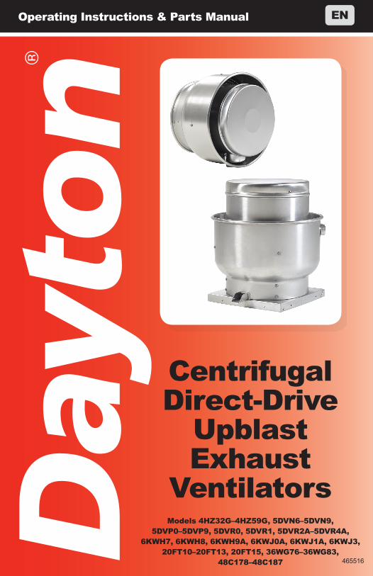
Operating Instructions & Parts Manual EN Centrifugal Direct-Drive Upblast Exhaust Ventilators 465516 Models 4HZ32G–4HZ59G, 5DVN6–5DVN9, 5DVP0–5DVP9, 5DVR0, 5DVR1, 5DVR2A–5DVR4A, 6KWH7, 6KWH8, 6KWH9A, 6KWJ0A, 6KWJ1A, 6KWJ3, 20FT10–20FT13, 20FT15, 36WG76–36WG83, 48C178–48C187
-
Upload
duongduong -
Category
Documents
-
view
227 -
download
0
Transcript of Centrifugal - grainger.com · Operating Instructions Parts Manual EN Centrifugal Direct-Drive...
Operating Instructions & Parts Manual EN
Centrifugal Direct-Drive
Upblast Exhaust
Ventilators
465516
Models 4HZ32G–4HZ59G, 5DVN6–5DVN9, 5DVP0–5DVP9, 5DVR0, 5DVR1, 5DVR2A–5DVR4A,
6KWH7, 6KWH8, 6KWH9A, 6KWJ0A, 6KWJ1A, 6KWJ3, 20FT10–20FT13, 20FT15, 36WG76–36WG83,
48C178–48C187
465516_CenDDUpblast V3_EN_ES_FR.indd 1 10/28/2015 4:13:02 PM
PLEASE READ AND SAVE THESE INSTRUCTIONS.
READ CAREFULLY BEFORE ATTEMPTING
TO ASSEMBLE, INSTALL, OPERATE OR MAINTAIN THE
PRODUCT DESCRIBED.
PROTECT YOURSELF AND OTHERS BY OBSERVING ALL
SAFETY INFORMATION. FAILURE TO COMPLY WITH INSTRUCTIONS
COULD RESULT IN PERSONAL INJURY AND/OR PROPERTY
DAMAGE! RETAIN INSTRUCTIONS FOR FUTURE REFERENCE.
PLEASE REFER TO BACK COVER FOR INFORMATION REGARDING
DAYTON’S WARRANTY AND OTHER IMPORTANT INFORMATION.
Model #: ___________________
Serial #: ___________________
Purch. Date: _______________
Form 5S6829 / Printed in USA04632 Version 3 06/2015
© 2004 - 2015 Dayton Electric Manufacturing Co.All Rights Reserved
465516_CenDDUpblast V3_EN_ES_FR.indd 2 10/28/2015 4:13:02 PM
1
SAFETY /
SPECIFIC
ATION
SA
SSEMB
LY / IN
STALLATIO
NO
PERATIO
NTR
OU
BLESH
OO
TING
MA
INTEN
AN
CE /
REPA
IRG
ETTING
STAR
TED
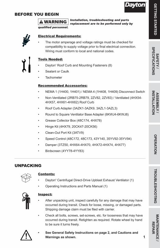
BEFORE YOU BEGINInstallation, troubleshooting and parts replacement are to be performed only by
qualified personnel.
Electrical Requirements:
• The motor amperage and voltage ratings must be checked for compatibility to supply voltage prior to final electrical connection. Wiring must conform to local and national codes.
Tools Needed:
• Dayton® Roof Curb and Mounting Fasteners (8)
• Sealant or Caulk
• Tachometer
Recommended Accessories:
• NEMA 1 (1H400, 1H401) / NEMA 4 (1H408, 1H409) Disconnect Switch
• Non-Ventilated (2RB75-2RB79, 2ZV82, 2ZV83) / Ventilated (4HX54-4HX57, 4HX61-4HX62) Roof Curb
• Roof Curb Adapter (3AZK1-3AZK9, 3AZL1-3AZL3)
• Round to Square Ventilator Base Adapter (6KWJ4-6KWJ8)
• Grease Collector Box (48C174, 4HX78)
• Hinge Kit (4HX79, 20CK47-20CK56)
• Clean-Out Port Kit (3ATV9)
• Speed Control (48C172, 48C173, 43Y140, 35YV92-35YV94)
• Damper (3TZ50, 4HX64-4HX70, 4HX72-4HX74, 4HX77)
• Birdscreen (4YY78-4YY83)
UNPACKING
Contents:
• Dayton® Centrifugal Direct-Drive Upblast Exhaust Ventilator (1)
• Operating Instructions and Parts Manual (1)
Inspect:
• After unpacking unit, inspect carefully for any damage that may have occurred during transit. Check for loose, missing, or damaged parts. Shipping damage claim must be filed with carrier.
• Check all bolts, screws, set-screws, etc. for looseness that may have occurred during transit. Retighten as required. Rotate wheel by hand to be sure it turns freely.
• See General Safety Instructions on page 2, and Cautions and Warnings as shown.
465516_CenDDUpblast V3_EN_ES_FR.indd 1 10/28/2015 4:13:03 PM
MA
INTE
NA
NC
E /
REP
AIR
TRO
UB
LESH
OO
TIN
GO
PER
ATIO
NA
SSEM
BLY
/ IN
STA
LLAT
ION
GET
TIN
G S
TAR
TED
2
SAFE
TY /
SPEC
IFIC
ATIO
NS
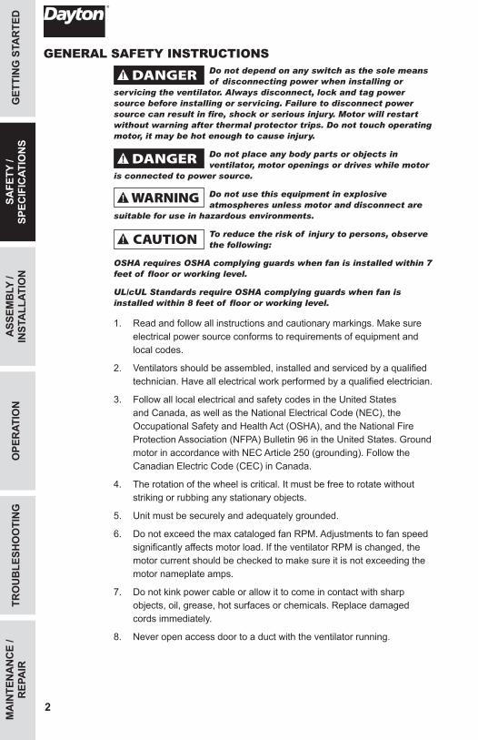
GENERAL SAFETY INSTRUCTIONSDo not depend on any switch as the sole means of disconnecting power when installing or
servicing the ventilator. Always disconnect, lock and tag power source before installing or servicing. Failure to disconnect power source can result in fire, shock or serious injury. Motor will restart without warning after thermal protector trips. Do not touch operating motor, it may be hot enough to cause injury.
Do not place any body parts or objects in ventilator, motor openings or drives while motor
is connected to power source.
Do not use this equipment in explosive atmospheres unless motor and disconnect are
suitable for use in hazardous environments.
To reduce the risk of injury to persons, observe the following:
OSHA requires OSHA complying guards when fan is installed within 7 feet of floor or working level.
UL/cUL Standards require OSHA complying guards when fan is installed within 8 feet of floor or working level.
1. Read and follow all instructions and cautionary markings. Make sure electrical power source conforms to requirements of equipment and local codes.
2. Ventilators should be assembled, installed and serviced by a qualified technician. Have all electrical work performed by a qualified electrician.
3. Follow all local electrical and safety codes in the United States and Canada, as well as the National Electrical Code (NEC), the Occupational Safety and Health Act (OSHA), and the National Fire Protection Association (NFPA) Bulletin 96 in the United States. Ground motor in accordance with NEC Article 250 (grounding). Follow the Canadian Electric Code (CEC) in Canada.
4. The rotation of the wheel is critical. It must be free to rotate without striking or rubbing any stationary objects.
5. Unit must be securely and adequately grounded.
6. Do not exceed the max cataloged fan RPM. Adjustments to fan speed significantly affects motor load. If the ventilator RPM is changed, the motor current should be checked to make sure it is not exceeding the motor nameplate amps.
7. Do not kink power cable or allow it to come in contact with sharp objects, oil, grease, hot surfaces or chemicals. Replace damaged cords immediately.
8. Never open access door to a duct with the ventilator running.
465516_CenDDUpblast V3_EN_ES_FR.indd 2 10/28/2015 4:13:04 PM
3
GETTIN
G STA
RTED
ASSEM
BLY /
INSTA
LLATION
OPER
ATION
TRO
UB
LESHO
OTIN
GM
AIN
TENA
NC
E / R
EPAIR
SAFETY /
SPECIFIC
ATION
S
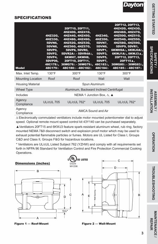
SPECIFICATIONS
Model
4HZ32G, 4HZ33G, 5DVN6, 5DVN8, 5DVP0, 5DVP2, 5DVP4, 5DVP06, 48C178∆, 48C179∆
20FT10, 20FT11, 4HZ40G, 4HZ41G, 4HZ44G, 4HZ45G, 4HZ48G, 4HZ49G, 4HZ52G, 4HZ53G, 4HZ56G, 4HZ57G,
5DVP8, 5DVR0, 5DVR2A∆ - 5DVR4A∆,
6KWH7, 6KWH8, 20FT10, 20FT11,
36WG76∆ - 36WG79∆, 48C180∆ - 48C182∆
4HZ34G, 4HZ35G, 5DVN7, 5DVN9, 5DVP1, 5DVP3, 5DVP5, 5DVP7,
48C183∆, 48C184∆
20FT12, 20FT13, 4HZ42G, 4HZ43G, 4HZ46G, 4HZ47G, 4HZ50G, 4HZ51G, 4HZ54G, 4HZ55G, 4HZ58G, 4HZ59G,
5DVP9, 5DVR1, 6KWH9A∆, 6KWJ0A∆, 6KWJ1A∆, 6KWJ3▲,
20FT12, 20FT13, 20FT15▲,
36WG80∆ - 36WG83∆, 48C185∆ - 48C187∆
Max. Inlet Temp. 130°F 300°F 130°F 300°F
Mounting Location Roof Roof Wall Wall
Housing Material Spun Aluminum
Wheel Type Aluminum, Backward Inclined Centrifugal
Includes NEMA 1 Junction Box, ∆, ▲Agency Compliance UL/cUL 705 UL/cUL 762* UL/cUL 705 UL/cUL 762*
Agency Compliance AMCA Sound and Air
∆ Electronically commutated ventilators include motor mounted potentiometer dial to adjust speed. Optional remote mount speed control kit 43Y140 can be purchased separately.▲Ventilators 20FT15 and 6KWJ3 feature spark-resistant aluminum wheel, rub ring, factory mounted NEMA 7&9 disconnect switch and explosion proof motor which may be used to exhaust potential flammable particles or fumes. Motors are UL Listed for Class I, Groups C&D and Class II, Groups F&G for hazardous locations. * Ventilators are UL/cUL Listed Subject 762 (YZHW) and comply with all requirements set forth in NFPA 96 Standard for Ventilation Control and Fire Protection Commercial Cooking Operations.
Dimensions (inches)
Figure 1 — Roof-Mount
B
CD
A
13/4"
Wal
l Op
enin
g
B
C
D
A E
Figure 2 — Wall-Mount
E53236MH12596
465516_CenDDUpblast V3_EN_ES_FR.indd 3 10/28/2015 4:13:05 PM
MA
INTE
NA
NC
E /
REP
AIR
TRO
UB
LESH
OO
TIN
GO
PER
ATIO
NA
SSEM
BLY
/ IN
STA
LLAT
ION
GET
TIN
G S
TAR
TED
4
SAFE
TY /
SPEC
IFIC
ATIO
NS
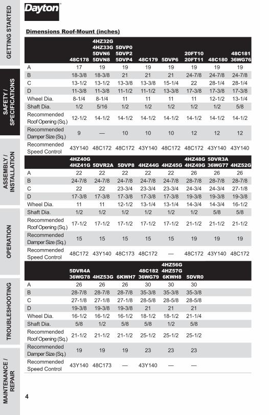
Dimensions Roof-Mount (inches)
48C178
4HZ32G 4HZ33G 5DVN6 5DVN8
5DVP0 5DVP2 5DVP4 48C179 5DVP6
20FT10 20FT11 48C180
48C18136WG76
A 17 19 19 19 19 19 19 19B 18-3/8 18-3/8 21 21 21 24-7/8 24-7/8 24-7/8C 13-1/2 13-1/2 13-3/8 13-3/8 15-1/4 22 28-1/4 28-1/4D 11-3/8 11-3/8 11-1/2 11-1/2 13-3/8 17-3/8 17-3/8 17-3/8Wheel Dia. 8-1/4 8-1/4 11 11 11 11 12-1/2 13-1/4Shaft Dia. 1/2 5/16 1/2 1/2 1/2 1/2 1/2 5/8Recommended Roof Opening (Sq.) 12-1/2 14-1/2 14-1/2 14-1/2 14-1/2 14-1/2 14-1/2 14-1/2
Recommended Damper Size (Sq.) 9 — 10 10 10 12 12 12
Recommended Speed Control 43Y140 48C172 48C172 43Y140 48C172 48C172 43Y140 43Y140
4HZ40G 4HZ41G 5DVR2A 5DVP8 4HZ44G 4HZ45G
4HZ48G 4HZ49G
5DVR3A36WG77 4HZ52G
A 22 22 22 22 22 26 26 26B 24-7/8 24-7/8 24-7/8 24-7/8 24-7/8 28-7/8 28-7/8 28-7/8C 22 22 23-3/4 23-3/4 23-3/4 24-3/4 24-3/4 27-1/8D 17-3/8 17-3/8 17-3/8 17-3/8 17-3/8 19-3/8 19-3/8 19-3/8Wheel Dia. 11 11 12-1/2 13-1/4 13-1/4 14-3/4 14-3/4 16-1/2Shaft Dia. 1/2 1/2 1/2 1/2 1/2 1/2 5/8 5/8Recommended Roof Opening (Sq.) 17-1/2 17-1/2 17-1/2 17-1/2 17-1/2 21-1/2 21-1/2 21-1/2
Recommended Damper Size (Sq.) 15 15 15 15 15 19 19 19
Recommended Speed Control 48C172 43Y140 48C173 48C172 — 48C172 43Y140 48C172
5DVR4A36WG78 4HZ53G 6KWH7
48C18236WG79
4HZ56G 4HZ57G 6KWH8 5DVR0
A 26 26 26 30 30 30B 28-7/8 28-7/8 28-7/8 35-3/8 35-3/8 35-3/8C 27-1/8 27-1/8 27-1/8 28-5/8 28-5/8 28-5/8D 19-3/8 19-3/8 19-3/8 21 21 21Wheel Dia. 16-1/2 16-1/2 16-1/2 18-1/2 18-1/2 21-1/4Shaft Dia. 5/8 1/2 5/8 5/8 1/2 5/8Recommended Roof Opening (Sq.) 21-1/2 21-1/2 21-1/2 25-1/2 25-1/2 25-1/2
Recommended Damper Size (Sq.) 19 19 19 23 23 23
Recommended Speed Control 43Y140 48C173 — 43Y140 — —
465516_CenDDUpblast V3_EN_ES_FR.indd 4 10/28/2015 4:13:05 PM
5
GETTIN
G STA
RTED
ASSEM
BLY /
INSTA
LLATION
OPER
ATION
TRO
UB
LESHO
OTIN
GM
AIN
TENA
NC
E / R
EPAIR
SAFETY /
SPECIFIC
ATION
S
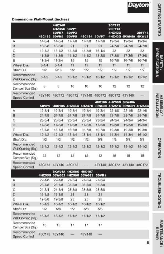
Dimensions Wall-Mount (inches)
48C183
4HZ34G 4HZ35G 5DVN7 5DVN9
5DVP1 5DVP3 5DVP5 48C184 5DVP7
20FT12 20FT13 4HZ42G 4HZ43G 6KWH9A
20FT15 6KWJ3
A 14-3/4 14-3/4 17-7/8 17-7/8 17-7/8 19-3/4 19-3/4 19-3/4B 18-3/8 18-3/8 21 21 21 24-7/8 24-7/8 24-7/8C 13-1/2 13-1/2 13-3/8 13-3/8 15-1/4 22 22 22D 11-3/8 11-3/8 11-1/2 11-1/2 13-3/8 17-3/8 17-3/8 17-3/8E 11-3/4 11-3/4 15 15 15 16-7/8 16-7/8 16-7/8Wheel Dia. 8-1/4 8-1/4 11 11 11 11 11 11Shaft Dia. 1/2 5/16 1/2 1/2 1/2 1/2 1/2 1/2Recommended Wall Opening (Sq.) 8-1/2 8-1/2 10-1/2 10-1/2 10-1/2 12-1/2 12-1/2 12-1/2
Recommended Damper Size (Sq.) 8 8 10 10 10 12 12 12
Recommended Speed Control 43Y140 48C172 48C172 43Y140 48C172 48C172 43Y140 —
5DVP9 48C185 4HZ46G 4HZ47G48C18636WG80
4HZ50G 4HZ51G
6KWJ0A36WG81 4HZ54G
A 19-3/4 19-3/4 19-3/4 19-3/4 19-3/4 22-1/8 22-1/8 22-1/8B 24-7/8 24-7/8 24-7/8 24-7/8 24-7/8 28-7/8 28-7/8 28-7/8C 23-3/4 23-3/4 23-3/4 23-3/4 23-3/4 24-3/4 24-3/4 24-3/4D 17-3/8 17-3/8 17-3/8 17-3/8 17-3/8 19-3/8 19-3/8 19-3/8E 16-7/8 16-7/8 16-7/8 16-7/8 16-7/8 19-3/8 19-3/8 19-3/8Wheel Dia. 12-1/2 12-1/2 13-1/4 13-1/4 13-1/4 14-3/4 14-3/4 16-1/2Shaft Dia. 1/2 1/2 1/2 1/2 5/8 1/2 5/8 5/8Recommended Wall Opening (Sq.) 12-1/2 12-1/2 12-1/2 12-1/2 12-1/2 15-1/2 15-1/2 15-1/2
Recommended Damper Size (Sq.) 12 12 12 12 12 15 15 15
Recommended Speed Control 48C173 43Y140 48C172 — 43Y140 48C172 43Y140 48C172
4HZ55G6KWJ1A36WG82
4HZ58G 4HZ59G
48C18736WG83 5DVR1
A 22-1/8 22-1/8 27-3/4 27-3/4 27-3/4B 28-7/8 28-7/8 35-3/8 35-3/8 35-3/8C 24-3/4 24-3/4 28-5/8 28-5/8 28-5/8D 19-3/8 19-3/8 21 21 21E 19-3/8 19-3/8 25 25 25Wheel Dia. 16-1/2 16-1/2 18-1/2 18-1/2 18-1/2Shaft Dia. 1/2 5/8 1/2 5/8 5/8Recommended Wall Opening (Sq.) 15-1/2 15-1/2 17-1/2 17-1/2 17-1/2
Recommended Damper Size (Sq.) 15 15 17 17 17
Recommended Speed Control 48C173 43Y140 — 43Y140 —
465516_CenDDUpblast V3_EN_ES_FR.indd 5 10/28/2015 4:13:05 PM
MA
INTE
NA
NC
E /
REP
AIR
TRO
UB
LESH
OO
TIN
GO
PER
ATIO
NA
SSEM
BLY
/ IN
STA
LLAT
ION
GET
TIN
G S
TAR
TED
6
SAFE
TY /
SPEC
IFIC
ATIO
NS
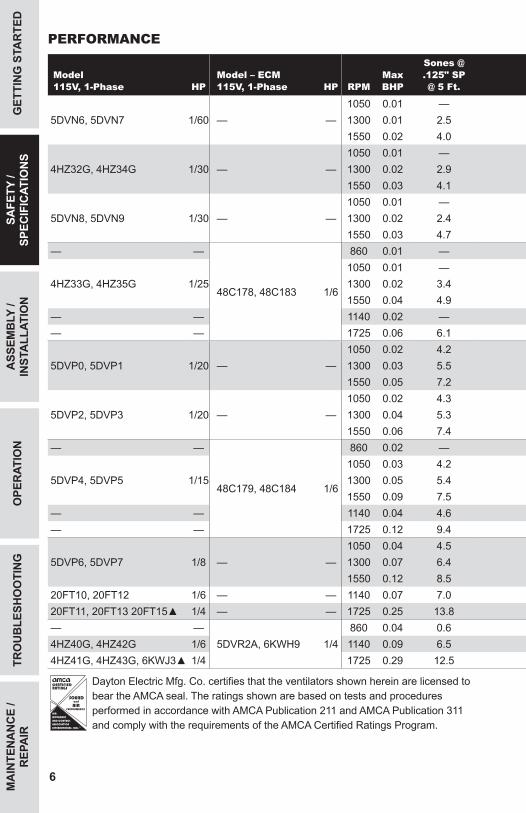
PERFORMANCE
Model115V, 1-Phase HP
Model – ECM115V, 1-Phase HP RPM
Max BHP
Sones @ .125" SP @ 5 Ft.
CFM Air Delivery @ Static Pressure Shown.000" .125" .250" .375" .500" .750" 1.00" 1.25" 1.50"
5DVN6, 5DVN7 1/60 — —1050 0.01 — 133 81 — — — — — — —1300 0.01 2.5 165 126 70 — — — — — —1550 0.02 4.0 197 164 128 — — — — — —
4HZ32G, 4HZ34G 1/301050 0.01 — 180 109 — — — — — — —
— — 1300 0.02 2.9 223 170 97 — — — — — —1550 0.03 4.1 266 222 172 95 — — — — —
5DVN8, 5DVN9 1/30 — —1050 0.01 — 250 171 — — — — — — —1300 0.02 2.4 309 255 152 — — — — — —1550 0.03 4.7 369 325 269 160 — — — — —
— —
48C178, 48C183 1/6
860 0.01 — 235 95 — — — — — — —
4HZ33G, 4HZ35G 1/251050 0.01 — 287 188 — — — — — — —1300 0.02 3.4 356 279 185 — — — — — —1550 0.04 4.9 424 359 291 204 — — — — —
— — 1140 0.02 — 312 222 — — — — — — —— — 1725 0.06 6.1 472 413 355 289 199 — — — —
5DVP0, 5DVP1 1/201050 0.02 4.2 325 247 133 — — — — — —
— — 1300 0.03 5.5 403 343 272 173 — — — — —1550 0.05 7.2 480 431 376 314 235 — — — —
5DVP2, 5DVP3 1/201050 0.02 4.3 389 305 182 — — — — — —
— — 1300 0.04 5.3 481 416 340 235 — — — — —1550 0.06 7.4 574 520 461 395 312 — — — —
— —
48C179, 48C184 1/6
860 0.02 — 450 324 — — — — — — —
5DVP4, 5DVP5 1/151050 0.03 4.2 549 451 306 — — — — — —1300 0.05 5.4 680 600 517 391 — — — — —1550 0.09 7.5 811 744 677 604 501 — — — —
— — 1140 0.04 4.6 596 505 395 — — — — — —— — 1725 0.12 9.4 903 842 782 722 652 420 — — —
5DVP6, 5DVP7 1/81050 0.04 4.5 711 570 381 — — — — — —
— — 1300 0.07 6.4 880 774 641 484 199 — — — —1550 0.12 8.5 1049 964 861 747 616 — — — —
20FT10, 20FT12 1/6 — — 1140 0.07 7.0 833 754 665 565 408 — — — —20FT11, 20FT13 20FT15▲ 1/4 — — 1725 0.25 13.8 1260 1209 1156 1100 1041 918 759 639 —— —
5DVR2A, 6KWH9 1/4860 0.04 0.6 732 625 481 — — — — — —
4HZ40G, 4HZ42G 1/6 1140 0.09 6.5 970 897 806 707 — — — — —4HZ41G, 4HZ43G, 6KWJ3▲ 1/4 1725 0.29 12.5 1468 1422 1373 1315 1255 1129 970 — —
R
®
AIR
MOVEMENT
AND CONTROL
ASSOCIATION
INTERNATIONAL, INC.
AIRPERFORMANCE
SOUNDand
Dayton Electric Mfg. Co. certifies that the ventilators shown herein are licensed to bear the AMCA seal. The ratings shown are based on tests and procedures performed in accordance with AMCA Publication 211 and AMCA Publication 311 and comply with the requirements of the AMCA Certified Ratings Program.
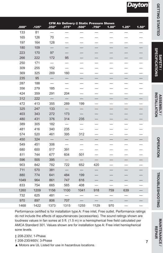
Performance certified is for installation type A: Free inlet, Free outlet. Performance ratings do not include the effects of appurtenances (accessories). The sound ratings shown are loudness values in fan sones at 5 ft. (1.5 m) in a hemispherical free field calculated per AMCA Standard 301. Values shown are for installation type A: Free inlet hemispherical sone levels.
‡ 208-230V, 1-Phase † 208-230/460V, 3-Phase ▲ Motors are UL Listed for use in hazardous locations.
465516_CenDDUpblast V3_EN_ES_FR.indd 6 10/28/2015 4:13:06 PM
7
GETTIN
G STA
RTED
ASSEM
BLY /
INSTA
LLATION
OPER
ATION
TRO
UB
LESHO
OTIN
GM
AIN
TENA
NC
E / R
EPAIR
SAFETY /
SPECIFIC
ATION
SPERFORMANCE
Model115V, 1-Phase HP
Model – ECM115V, 1-Phase HP RPM
Max BHP
Sones @ .125" SP @ 5 Ft.
CFM Air Delivery @ Static Pressure Shown.000" .125" .250" .375" .500" .750" 1.00" 1.25" 1.50"
5DVN6, 5DVN7 1/60 — —1050 0.01 — 133 81 — — — — — — —1300 0.01 2.5 165 126 70 — — — — — —1550 0.02 4.0 197 164 128 — — — — — —
4HZ32G, 4HZ34G 1/301050 0.01 — 180 109 — — — — — — —
— — 1300 0.02 2.9 223 170 97 — — — — — —1550 0.03 4.1 266 222 172 95 — — — — —
5DVN8, 5DVN9 1/30 — —1050 0.01 — 250 171 — — — — — — —1300 0.02 2.4 309 255 152 — — — — — —1550 0.03 4.7 369 325 269 160 — — — — —
— —
48C178, 48C183 1/6
860 0.01 — 235 95 — — — — — — —
4HZ33G, 4HZ35G 1/251050 0.01 — 287 188 — — — — — — —1300 0.02 3.4 356 279 185 — — — — — —1550 0.04 4.9 424 359 291 204 — — — — —
— — 1140 0.02 — 312 222 — — — — — — —— — 1725 0.06 6.1 472 413 355 289 199 — — — —
5DVP0, 5DVP1 1/201050 0.02 4.2 325 247 133 — — — — — —
— — 1300 0.03 5.5 403 343 272 173 — — — — —1550 0.05 7.2 480 431 376 314 235 — — — —
5DVP2, 5DVP3 1/201050 0.02 4.3 389 305 182 — — — — — —
— — 1300 0.04 5.3 481 416 340 235 — — — — —1550 0.06 7.4 574 520 461 395 312 — — — —
— —
48C179, 48C184 1/6
860 0.02 — 450 324 — — — — — — —
5DVP4, 5DVP5 1/151050 0.03 4.2 549 451 306 — — — — — —1300 0.05 5.4 680 600 517 391 — — — — —1550 0.09 7.5 811 744 677 604 501 — — — —
— — 1140 0.04 4.6 596 505 395 — — — — — —— — 1725 0.12 9.4 903 842 782 722 652 420 — — —
5DVP6, 5DVP7 1/81050 0.04 4.5 711 570 381 — — — — — —
— — 1300 0.07 6.4 880 774 641 484 199 — — — —1550 0.12 8.5 1049 964 861 747 616 — — — —
20FT10, 20FT12 1/6 — — 1140 0.07 7.0 833 754 665 565 408 — — — —20FT11, 20FT13 20FT15▲ 1/4 — — 1725 0.25 13.8 1260 1209 1156 1100 1041 918 759 639 —— —
5DVR2A, 6KWH9 1/4860 0.04 0.6 732 625 481 — — — — — —
4HZ40G, 4HZ42G 1/6 1140 0.09 6.5 970 897 806 707 — — — — —4HZ41G, 4HZ43G, 6KWJ3▲ 1/4 1725 0.29 12.5 1468 1422 1373 1315 1255 1129 970 — —
R
®
AIR
MOVEMENT
AND CONTROL
ASSOCIATION
INTERNATIONAL, INC.
AIRPERFORMANCE
SOUNDand
Dayton Electric Mfg. Co. certifies that the ventilators shown herein are licensed to bear the AMCA seal. The ratings shown are based on tests and procedures performed in accordance with AMCA Publication 211 and AMCA Publication 311 and comply with the requirements of the AMCA Certified Ratings Program.
Performance certified is for installation type A: Free inlet, Free outlet. Performance ratings do not include the effects of appurtenances (accessories). The sound ratings shown are loudness values in fan sones at 5 ft. (1.5 m) in a hemispherical free field calculated per AMCA Standard 301. Values shown are for installation type A: Free inlet hemispherical sone levels.
‡ 208-230V, 1-Phase † 208-230/460V, 3-Phase ▲ Motors are UL Listed for use in hazardous locations.
465516_CenDDUpblast V3_EN_ES_FR.indd 7 10/28/2015 4:13:06 PM
MA
INTE
NA
NC
E /
REP
AIR
TRO
UB
LESH
OO
TIN
GO
PER
ATIO
NA
SSEM
BLY
/ IN
STA
LLAT
ION
GET
TIN
G S
TAR
TED
8
SAFE
TY /
SPEC
IFIC
ATIO
NS
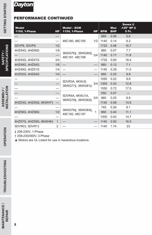
PERFORMANCE CONTINUED
Model115V, 1-Phase HP
Model – ECM115V, 1-Phase HP RPM
Max BHP
Sones @ .125" SP @
5 Ft.CFM Air Delivery @ Static Pressure Shown
.000" .125" .250" .375" .500" .750" 1.00" 1.25" 1.50"
— —48C180, 48C185 1/2
860 0.06 5.6 1015 905 781 581 — — — — —— — 1140 0.14 8.2 1346 1261 1180 1091 981 — — — —5DVP8, 5DVP9 1/2 1725 0.48 16.7 2037 1979 1923 1869 1816 1710 1571 1406 11764HZ44G, 4HZ46G 1/8
36WG76‡, 36WG80‡, 48C181, 48C186 3/4
860 0.07 7.7 1180 1057 914 675 — — — — —— — 1140 0.17 11.8 1564 1471 1379 1280 1144 — — — —4HZ45G, 4HZ47G 3/4 1725 0.60 18.4 2366 2305 2244 2183 2122 1994 1838 1646 13654HZ48G, 4HZ50G 1/8 — — 860 0.12 7.1 1558 1427 1264 1034 — — — — —4HZ49G, 4HZ51G 1/4 — — 1140 0.29 11.0 2065 1973 1864 1745 1605 1167 — — —4HZ52G, 4HZ54G 1/4 — — 860 0.25 9.9 2472 2315 2126 1918 1680 — — — —— —
5DVR3A, 6KWJ0, 36WG77‡, 36WG81‡
3/41050 0.22 9.8 1902 1800 1680 1540 1372 — — — —
— — 1300 0.43 12.8 2355 2277 2186 2086 1979 1717 1269 — —— — 1550 0.72 17.5 2808 2743 2671 2594 2509 2329 2110 1823 1349— —
5DVR4A, 6KWJ1A, 36WG78‡, 36WG82‡
3/4550 0.07 — 1581 1303 — — — — — — —
— — 860 0.25 9.9 2472 2315 2156 1918 1680 — — — —4HZ53G, 4HZ55G, 6KWH7† — 1140 0.58 14.8 3277 3161 3035 2896 2745 2421 1983 — —— —
36WG79‡, 36WG83‡, 48C182, 48C187 1
745 0.26 8.1 2815 2617 2448 2143 1763 — — — —4HZ56G, 4HZ58G 1/2 860 0.40 11.1 3249 3074 2922 2732 2474 — — — —— — 1000 0.63 14.7 3778 3625 3486 3362 3190 2738 — — —4HZ57G, 4HZ59G, 6KWH8† 1 — — 1140 0.93 16.5 4307 4173 4045 3927 3822 3470 3072 2477 —5DVR0†, 5DVR1† 2 — — 1140 1.74 23 6412 6224 6036 5855 5674 5283 4837 4276 3445
‡ 208-230V, 1-Phase † 208-230/460V, 3-Phase ▲ Motors are UL Listed for use in hazardous locations.
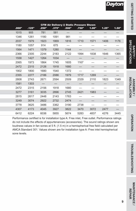
Performance certified is for installation type A: Free inlet, Free outlet. Performance ratings do not include the effects of appurtenances (accessories). The sound ratings shown are loudness values in fan sones at 5 ft. (1.5 m) in a hemispherical free field calculated per AMCA Standard 301. Values shown are for installation type A: Free inlet hemispherical sone levels.
465516_CenDDUpblast V3_EN_ES_FR.indd 8 10/28/2015 4:13:06 PM
9
GETTIN
G STA
RTED
ASSEM
BLY /
INSTA
LLATION
OPER
ATION
TRO
UB
LESHO
OTIN
GM
AIN
TENA
NC
E / R
EPAIR
SAFETY /
SPECIFIC
ATION
S
PERFORMANCE CONTINUED
Model115V, 1-Phase HP
Model – ECM115V, 1-Phase HP RPM
Max BHP
Sones @ .125" SP @
5 Ft.CFM Air Delivery @ Static Pressure Shown
.000" .125" .250" .375" .500" .750" 1.00" 1.25" 1.50"
— —48C180, 48C185 1/2
860 0.06 5.6 1015 905 781 581 — — — — —— — 1140 0.14 8.2 1346 1261 1180 1091 981 — — — —5DVP8, 5DVP9 1/2 1725 0.48 16.7 2037 1979 1923 1869 1816 1710 1571 1406 11764HZ44G, 4HZ46G 1/8
36WG76‡, 36WG80‡, 48C181, 48C186 3/4
860 0.07 7.7 1180 1057 914 675 — — — — —— — 1140 0.17 11.8 1564 1471 1379 1280 1144 — — — —4HZ45G, 4HZ47G 3/4 1725 0.60 18.4 2366 2305 2244 2183 2122 1994 1838 1646 13654HZ48G, 4HZ50G 1/8 — — 860 0.12 7.1 1558 1427 1264 1034 — — — — —4HZ49G, 4HZ51G 1/4 — — 1140 0.29 11.0 2065 1973 1864 1745 1605 1167 — — —4HZ52G, 4HZ54G 1/4 — — 860 0.25 9.9 2472 2315 2126 1918 1680 — — — —— —
5DVR3A, 6KWJ0, 36WG77‡, 36WG81‡
3/41050 0.22 9.8 1902 1800 1680 1540 1372 — — — —
— — 1300 0.43 12.8 2355 2277 2186 2086 1979 1717 1269 — —— — 1550 0.72 17.5 2808 2743 2671 2594 2509 2329 2110 1823 1349— —
5DVR4A, 6KWJ1A, 36WG78‡, 36WG82‡
3/4550 0.07 — 1581 1303 — — — — — — —
— — 860 0.25 9.9 2472 2315 2156 1918 1680 — — — —4HZ53G, 4HZ55G, 6KWH7† — 1140 0.58 14.8 3277 3161 3035 2896 2745 2421 1983 — —— —
36WG79‡, 36WG83‡, 48C182, 48C187 1
745 0.26 8.1 2815 2617 2448 2143 1763 — — — —4HZ56G, 4HZ58G 1/2 860 0.40 11.1 3249 3074 2922 2732 2474 — — — —— — 1000 0.63 14.7 3778 3625 3486 3362 3190 2738 — — —4HZ57G, 4HZ59G, 6KWH8† 1 — — 1140 0.93 16.5 4307 4173 4045 3927 3822 3470 3072 2477 —5DVR0†, 5DVR1† 2 — — 1140 1.74 23 6412 6224 6036 5855 5674 5283 4837 4276 3445
‡ 208-230V, 1-Phase † 208-230/460V, 3-Phase ▲ Motors are UL Listed for use in hazardous locations.
Performance certified is for installation type A: Free inlet, Free outlet. Performance ratings do not include the effects of appurtenances (accessories). The sound ratings shown are loudness values in fan sones at 5 ft. (1.5 m) in a hemispherical free field calculated per AMCA Standard 301. Values shown are for installation type A: Free inlet hemispherical sone levels.
465516_CenDDUpblast V3_EN_ES_FR.indd 9 10/28/2015 4:13:06 PM
MA
INTE
NA
NC
E /
REP
AIR
TRO
UB
LESH
OO
TIN
GO
PER
ATIO
NSA
FETY
/ SP
ECIF
ICAT
ION
SG
ETTI
NG
STA
RTE
D
10
ASS
EMB
LY /
INST
ALL
ATIO
N
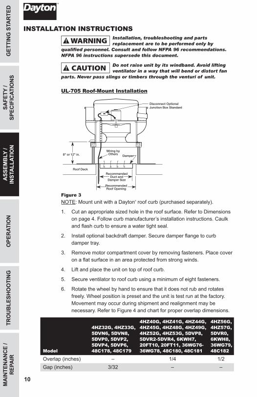
INSTALLATION INSTRUCTIONSInstallation, troubleshooting and parts replacement are to be performed only by
qualified personnel. Consult and follow NFPA 96 recommendations. NFPA 96 instructions supersede this document.
Do not raise unit by its windband. Avoid lifting ventilator in a way that will bend or distort fan
parts. Never pass slings or timbers through the venturi of unit.
UL-705 Roof-Mount Installation
Damper
RecommendedWall Opening
MountingBolt Hole
Circle
RecommendedDuct and
Damper Size
Wall
Wiring byothersRecommended
Duct andDamper Size
RecommendedRoof Opening
Wiring byOthers
Disconnect OptionalJunction Box Standard
Roof Deck
Damper8" or 12" in.
DisconnectOptional
Figure 3NOTE: Mount unit with a Dayton® roof curb (purchased separately).
1. Cut an appropriate sized hole in the roof surface. Refer to Dimensions on page 4. Follow curb manufacturer’s installation instructions. Caulk and flash curb to ensure a water tight seal.
2. Install optional backdraft damper. Secure damper flange to curb damper tray.
3. Remove motor compartment cover by removing fasteners. Place cover on a flat surface in an area protected from strong winds.
4. Lift and place the unit on top of roof curb.
5. Secure ventilator to roof curb using a minimum of eight fasteners.
6. Rotate the wheel by hand to ensure that it does not rub and rotates freely. Wheel position is preset and the unit is test run at the factory. Movement may occur during shipment and realignment may be necessary. Refer to Figure 4 and chart for proper overlap dimensions.
Model
4HZ32G, 4HZ33G, 5DVN6, 5DVN8, 5DVP0, 5DVP2, 5DVP4, 5DVP6, 48C178, 48C179
4HZ40G, 4HZ41G, 4HZ44G, 4HZ45G, 4HZ48G, 4HZ49G, 4HZ52G, 4HZ53G, 5DVP8, 5DVR2-5DVR4, 6KWH7, 20FT10, 20FT11, 36WG76-36WG78, 48C180, 48C181
4HZ56G, 4HZ57G, 5DVR0, 6KWH8, 36WG79, 48C182
Overlap (inches) – 1/4 1/2Gap (inches) 3/32 – –
465516_CenDDUpblast V3_EN_ES_FR.indd 10 10/28/2015 4:13:07 PM
11
GETTIN
G STA
RTED
SAFETY /
SPECIFIC
ATION
SO
PERATIO
NTR
OU
BLESH
OO
TING
MA
INTEN
AN
CE /
REPA
IR
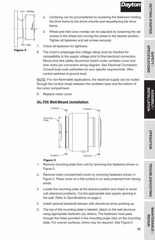
a. Centering can be accomplished by loosening the fasteners holding the drive frame to the shock mounts and repositioning the drive frame.
b. Wheel and inlet cone overlap can be adjusted by loosening the set screws in the wheel and moving the wheel to the desired position. Tighten all fasteners and set screws securely.
7. Check all fasteners for tightness.
8. The motor’s amperage and voltage rating must be checked for compatibility to the supply voltage prior to final electrical connection. Mount and wire safety disconnect switch under ventilator cover and wire motor per connection wiring diagram. See Electrical Connection. Consult local code authorities for your specific requirements. Wire control switches at ground level.
NOTE: For non-flammable applications, the electrical supply can be routed through the conduit chase between the ventilator base and the bottom of the motor compartment.
9. Replace motor cover.
UL-705 Wall-Mount Installation
Figure 51. Remove mounting plate from unit by removing the fasteners shown in
Figure 5.
2. Remove motor compartment cover by removing fasteners shown in Figure 5. Place cover on a flat surface in an area protected from strong winds.
3. Locate the mounting plate at the desired position and check to avoid unit clearance problems. Cut the appropriate size square opening in the wall. Refer to Specifications on page 5.
4. Install optional backdraft damper with directional arrow pointing up.
5. The top of the mounting plate is labeled, attach to the wall structure using appropriate fasteners (by others). The fasteners must pass through the holes provided in the mounting angle clips on the mounting plate. For uneven surfaces, shims may be required. See Figure 6.
ASSEM
BLY /
INSTA
LLATION
Figure 4
Disconnect (Optional)
Junction Box(Standard)
Damper
RecommendedWall Opening
MountingBolt Hole
Circle
RecommendedDuct and
Damper Size
Wiring(by others)
Wall
MountingPlate
Fastener Fastener
Fastener Fastener
Mounting PlateFront View
“TOP” Decal
Wall
BreatherTube
HorizontalSupport Channel
Fasteners
TOP
Square Wall
Opening
MountingPlate
MountingAngle Clip
MountingAngle Clip
Fastener(by others)
Fastener(by others)
Breather Tube
Overlap
Gap
465516_CenDDUpblast V3_EN_ES_FR.indd 11 10/28/2015 4:13:07 PM
MA
INTE
NA
NC
E /
REP
AIR
TRO
UB
LESH
OO
TIN
GO
PER
ATIO
NSA
FETY
/ SP
ECIF
ICAT
ION
SG
ETTI
NG
STA
RTE
D
12
ASS
EMB
LY /
INST
ALL
ATIO
N
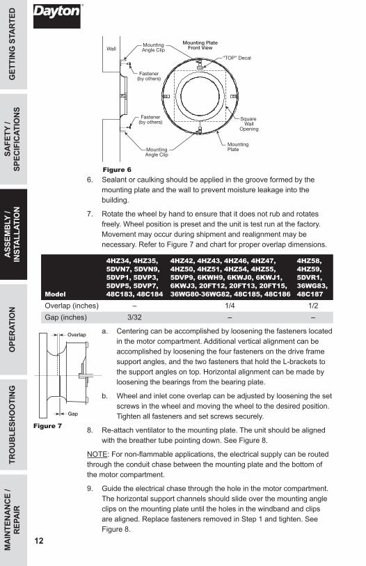
Figure 66. Sealant or caulking should be applied in the groove formed by the
mounting plate and the wall to prevent moisture leakage into the building.
7. Rotate the wheel by hand to ensure that it does not rub and rotates freely. Wheel position is preset and the unit is test run at the factory. Movement may occur during shipment and realignment may be necessary. Refer to Figure 7 and chart for proper overlap dimensions.
Model
4HZ34, 4HZ35, 5DVN7, 5DVN9, 5DVP1, 5DVP3, 5DVP5, 5DVP7, 48C183, 48C184
4HZ42, 4HZ43, 4HZ46, 4HZ47, 4HZ50, 4HZ51, 4HZ54, 4HZ55, 5DVP9, 6KWH9, 6KWJ0, 6KWJ1, 6KWJ3, 20FT12, 20FT13, 20FT15, 36WG80-36WG82, 48C185, 48C186
4HZ58, 4HZ59, 5DVR1, 36WG83, 48C187
Overlap (inches) – 1/4 1/2Gap (inches) 3/32 – –
a. Centering can be accomplished by loosening the fasteners located in the motor compartment. Additional vertical alignment can be accomplished by loosening the four fasteners on the drive frame support angles, and the two fasteners that hold the L-brackets to the support angles on top. Horizontal alignment can be made by loosening the bearings from the bearing plate.
b. Wheel and inlet cone overlap can be adjusted by loosening the set screws in the wheel and moving the wheel to the desired position. Tighten all fasteners and set screws securely.
8. Re-attach ventilator to the mounting plate. The unit should be aligned with the breather tube pointing down. See Figure 8.
NOTE: For non-flammable applications, the electrical supply can be routed through the conduit chase between the mounting plate and the bottom of the motor compartment.
9. Guide the electrical chase through the hole in the motor compartment. The horizontal support channels should slide over the mounting angle clips on the mounting plate until the holes in the windband and clips are aligned. Replace fasteners removed in Step 1 and tighten. See Figure 8.
Disconnect (Optional)
Junction Box(Standard)
Damper
RecommendedWall Opening
MountingBolt Hole
Circle
RecommendedDuct and
Damper Size
Wiring(by others)
Wall
MountingPlate
Fastener Fastener
Fastener Fastener
Mounting PlateFront View
“TOP” Decal
Wall
BreatherTube
HorizontalSupport Channel
Fasteners
TOP
Square Wall
Opening
MountingPlate
MountingAngle Clip
MountingAngle Clip
Fastener(by others)
Fastener(by others)
Breather Tube
Overlap
Gap
Figure 7
465516_CenDDUpblast V3_EN_ES_FR.indd 12 10/28/2015 4:13:07 PM
13
GETTIN
G STA
RTED
SAFETY /
SPECIFIC
ATION
SO
PERATIO
NTR
OU
BLESH
OO
TING
MA
INTEN
AN
CE /
REPA
IRA
SSEMB
LY / IN
STALLATIO
N
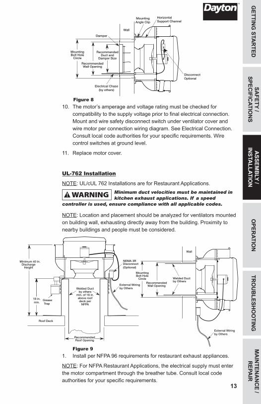
Figure 810. The motor’s amperage and voltage rating must be checked for
compatibility to the supply voltage prior to final electrical connection. Mount and wire safety disconnect switch under ventilator cover and wire motor per connection wiring diagram. See Electrical Connection. Consult local code authorities for your specific requirements. Wire control switches at ground level.
11. Replace motor cover.
UL-762 Installation
NOTE: UL/cUL 762 Installations are for Restaurant Applications.Minimum duct velocities must be maintained in kitchen exhaust applications. If a speed
controller is used, ensure compliance with all applicable codes.
NOTE: Location and placement should be analyzed for ventilators mounted on building wall, exhausting directly away from the building. Proximity to nearby buildings and people must be considered.
Figure 91. Install per NFPA 96 requirements for restaurant exhaust appliances.
NOTE: For NFPA Restaurant Applications, the electrical supply must enter the motor compartment through the breather tube. Consult local code authorities for your specific requirements.
Damper
RecommendedWall Opening
MountingBolt Hole
Circle
RecommendedDuct and
Damper Size
Wall
Electrical Chase(by others)Recommended
Duct andDamper Size
RecommendedRoof Opening
Wiring byOthers
Disconnect OptionalJunction Box Standard
Roof Deck
Damper8" or 12" in.
DisconnectOptional
HorizontalSupport Channel
MountingAngle Clip
Welded Ductby others
min. of 18 in.above roofdeck per
NFPA
NEMA 3RDisconnect(Optional)
by Others
RecommendedRoof Opening
Roof Deck
Minimum 40 in.Discharge
Height
18 in.min.
GreaseTrap
External Wiring
Wal
l Op
enin
g
Dam
per
Fra
me
Siz
e
Dam
per
Siz
e
Mo
untin
g H
ole
Bo
lt C
ircle
Welded Ductby OthersRecommended
Wall Opening
MountingBolt Hole
Circle
Wall
by Others
Welded Ductby others
min. of 18 in.above roofdeck per
NFPA
NEMA 3RDisconnect(Optioanl)
by Others
RecommendedRoof Opening
Roof Deck
Minimum 40 in.Discharge
Height
8 in. min.
GreaseTrap
Vented CurbExtension
External Wiring
External Wiring
465516_CenDDUpblast V3_EN_ES_FR.indd 13 10/28/2015 4:13:08 PM
MA
INTE
NA
NC
E /
REP
AIR
TRO
UB
LESH
OO
TIN
GO
PER
ATIO
NSA
FETY
/ SP
ECIF
ICAT
ION
SG
ETTI
NG
STA
RTE
D
14
ASS
EMB
LY /
INST
ALL
ATIO
N
2. Duct size must be equal to or larger than inlet opening. Some local codes require a continuous weld between duct and inlet.
3. Keep motor cooling tube clear from obstructions.
4. The following accessories may be required by NFPA-96 depending upon installation; Grease Collector Box, Hinge Kit, Clean-out Port, Vented Roof Curb and External Junction Box.
NOTE: A drain trough is provided on all Dayton roof mount upblast ventilators. Collection for grease and residue must be provided.
Do not use a damper in any kitchen exhaust application.
Electrical ConnectionComply with all local codes including the National Electrical Code (NEC) and National Fire
Protection Act (NFPA).
Install in accordance to NEC 70 and NFPA requirements.
IMPORTANT: Exhaust ventilators used in kitchen ventilation applications must have external wiring.
NOTE: Refer to motor nameplate for wiring procedures. Refer to switch manufacturer for installation and wiring procedures.
1. Motor and ventilator must be securely grounded (bare metal) to a suitable electric ground, such as a grounded water pipe or ground wire system.
NOTE: Motor and disconnect must be classified as hazardous for 20FT15 and 6KWJ3 ventilators to be suitable for use in hazardous environments. Installation must be performed by qualified personnel with suitable motor and disconnect for application.
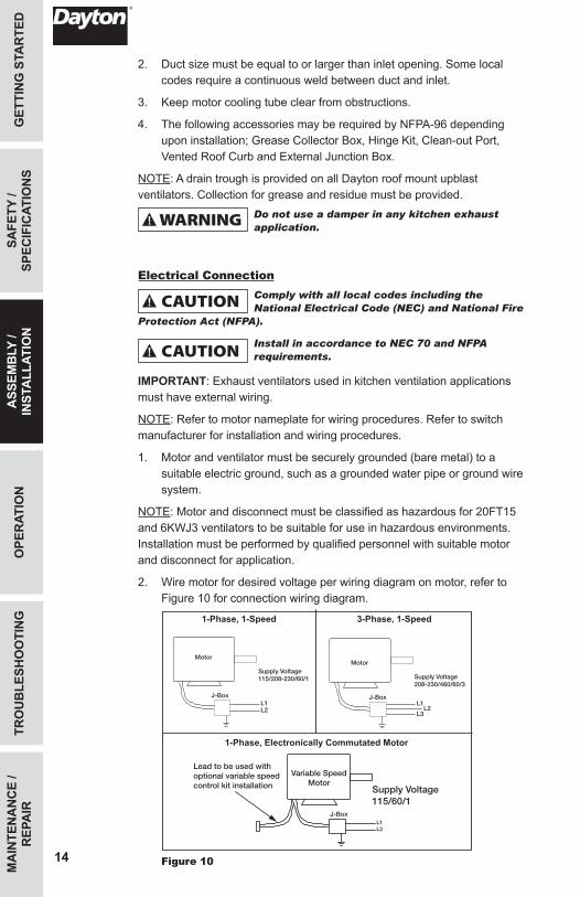
2. Wire motor for desired voltage per wiring diagram on motor, refer to Figure 10 for connection wiring diagram.
Motor
Supply Voltage115/208-230/60/1
L1L2
L1
L3L2
Motor
J-Box
J-Box
Supply Voltage208-230/460/60/3
Motor
Supply Voltage115/208-230/60/1
L1L2
L1
L3L2
Motor
J-Box
J-Box
Supply Voltage208-230/460/60/3
1-Phase, 1-Speed
1-Phase, Electronically Commutated Motor
3-Phase, 1-Speed
Variable SpeedMotor
L1
115/60/1J-Box
Supply Voltage
L2
Lead to be used withoptional variable speedcontrol kit installation
Figure 10
465516_CenDDUpblast V3_EN_ES_FR.indd 14 10/28/2015 4:13:09 PM
15
GETTIN
G STA
RTED
SAFETY /
SPECIFIC
ATION
SA
SSEMB
LY / IN
STALLATIO
NTR
OU
BLESH
OO
TING
MA
INTEN
AN
CE /
REPA
IRO
PERATIO
N
OPERATION1. Before starting up or operating the unit, check all fasteners for
tightness. In particular, check set screws in wheel hub. While in the OFF position, or before connecting the ventilator to power, turn the ventilator wheel by hand to be sure it is not striking the orifice or any obstacle.
2. Check wheel rotation (viewing from the shaft side) by momentarily energizing the unit. Rotation should be clockwise and correspond to the rotation decal on the unit.
IMPORTANT: Rotation of the wheel is critical and incorrect rotation will result in reduced air performance, increased motor loading and possible motor burnout.
3. When the ventilator is started, observe the operation and check for any unusual noises.
4. With the system in full operation and all ductwork attached, measure current (amps) input to the motor and compare with the nameplate rating (full-load amps) to determine if the motor is operating under safe load conditions.
5. Keep inlets and approaches to ventilator clean and free from obstruction.
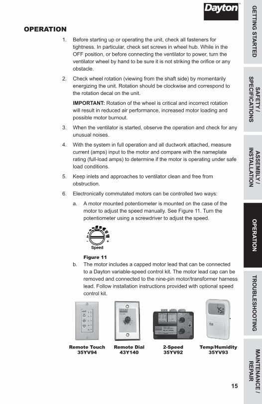
6. Electronically commutated motors can be controlled two ways:
a. A motor mounted potentiometer is mounted on the case of the motor to adjust the speed manually. See Figure 11. Turn the potentiometer using a screwdriver to adjust the speed.
Figure 11b. The motor includes a capped motor lead that can be connected
to a Dayton variable-speed control kit. The motor lead cap can be removed and connected to the nine-pin motor/transformer harness lead. Follow installation instructions provided with optional speed control kit.
Remote Touch
35YV94
Remote Dial
43Y140
2-Speed 35YV92
Temp/Humidity
35YV93
465516_CenDDUpblast V3_EN_ES_FR.indd 15 10/28/2015 4:13:09 PM
MA
INTE
NA
NC
E /
REP
AIR
OPE
RAT
ION
ASS
EMB
LY /
INST
ALL
ATIO
NSA
FETY
/ SP
ECIF
ICAT
ION
SG
ETTI
NG
STA
RTE
D
16
TRO
UB
LESH
OO
TIN
G
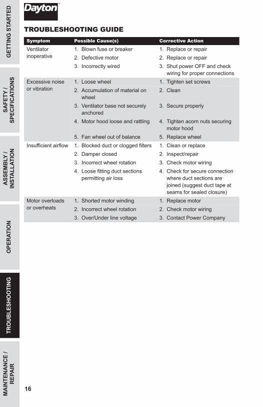
TROUBLESHOOTING GUIDESymptom Possible Cause(s) Corrective Action
Ventilator inoperative
1. Blown fuse or breaker 1. Replace or repair2. Defective motor 2. Replace or repair3. Incorrectly wired 3. Shut power OFF and check
wiring for proper connectionsExcessive noise or vibration
1. Loose wheel 1. Tighten set screws2. Accumulation of material on
wheel2. Clean
3. Ventilator base not securely anchored
3. Secure properly
4. Motor hood loose and rattling 4. Tighten acorn nuts securing motor hood
5. Fan wheel out of balance 5. Replace wheelInsufficient airflow 1. Blocked duct or clogged filters 1. Clean or replace
2. Damper closed 2. Inspect/repair3. Incorrect wheel rotation 3. Check motor wiring4. Loose fitting duct sections
permitting air loss4. Check for secure connection
where duct sections are joined (suggest duct tape at seams for sealed closure)
Motor overloads or overheats
1. Shorted motor winding 1. Replace motor2. Incorrect wheel rotation 2. Check motor wiring3. Over/Under line voltage 3. Contact Power Company
465516_CenDDUpblast V3_EN_ES_FR.indd 16 10/28/2015 4:13:09 PM
17
GETTIN
G STA
RTED
SAFETY /
SPECIFIC
ATION
SA
SSEMB
LY / IN
STALLATIO
NO
PERATIO
NTR
OU
BLESH
OO
TING
MA
INTEN
AN
CE /
REPA
IR
MAINTENANCEDisconnect and lockout power source before servicing.
Uneven cleaning of the wheel will produce an out of balance condition that will cause
vibration in the ventilator.
1. Depending on the usage and severity of the contaminated air, a regularly scheduled inspection for cleaning the ventilator wheel, housing and surrounding areas should be established. Severe applications may require weekly inspection.
IMPORTANT: Follow NEC 70 for cleaning when ventilator is installed on restaurant exhaust appliances.
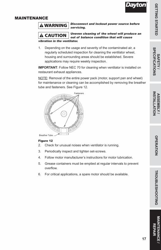
NOTE: Removal of the entire power pack (motor, support pan and wheel) for maintenance or cleaning can be accomplished by removing the breather tube and fasteners. See Figure 12.
Fasteners
Breather Tube
Figure 122. Check for unusual noises when ventilator is running.
3. Periodically inspect and tighten set-screws.
4. Follow motor manufacturer’s instructions for motor lubrication.
5. Grease containers must be emptied at regular intervals to prevent overflow.
6. For critical applications, a spare motor should be available.
465516_CenDDUpblast V3_EN_ES_FR.indd 17 10/28/2015 4:13:10 PM
For Repair Parts, call 1-800-Grainger24 hours a day – 365 days a year
Please provide following information:-Model number-Serial number (if any)-Part description and number as shown in parts list
MA
INTE
NA
NC
E /
REP
AIR
TRO
UB
LESH
OO
TIN
GO
PER
ATIO
NA
SSEM
BLY
/ IN
STA
LLAT
ION
SAFE
TY /
SPEC
IFIC
ATIO
NS
GET
TIN
G S
TAR
TED
18
MA
INTE
NA
NC
E /
REP
AIR
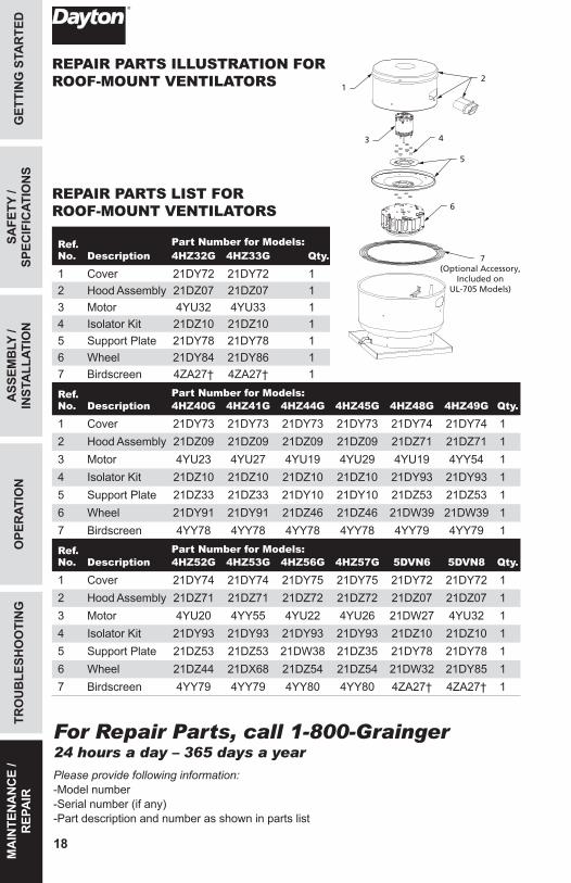
Ref. No. Description
Part Number for Models:4HZ32G 4HZ33G Qty.
1 Cover 21DY72 21DY72 12 Hood Assembly 21DZ07 21DZ07 13 Motor 4YU32 4YU33 14 Isolator Kit 21DZ10 21DZ10 15 Support Plate 21DY78 21DY78 16 Wheel 21DY84 21DY86 17 Birdscreen 4ZA27† 4ZA27† 1
Ref. No. Description
Part Number for Models: Qty.4HZ40G 4HZ41G 4HZ44G 4HZ45G 4HZ48G 4HZ49G
1 Cover 21DY73 21DY73 21DY73 21DY73 21DY74 21DY74 12 Hood Assembly 21DZ09 21DZ09 21DZ09 21DZ09 21DZ71 21DZ71 13 Motor 4YU23 4YU27 4YU19 4YU29 4YU19 4YY54 14 Isolator Kit 21DZ10 21DZ10 21DZ10 21DZ10 21DY93 21DY93 15 Support Plate 21DZ33 21DZ33 21DY10 21DY10 21DZ53 21DZ53 16 Wheel 21DY91 21DY91 21DZ46 21DZ46 21DW39 21DW39 17 Birdscreen 4YY78 4YY78 4YY78 4YY78 4YY79 4YY79 1
Ref. No. Description
Part Number for Models: Qty.4HZ52G 4HZ53G 4HZ56G 4HZ57G 5DVN6 5DVN8
1 Cover 21DY74 21DY74 21DY75 21DY75 21DY72 21DY72 12 Hood Assembly 21DZ71 21DZ71 21DZ72 21DZ72 21DZ07 21DZ07 13 Motor 4YU20 4YY55 4YU22 4YU26 21DW27 4YU32 14 Isolator Kit 21DY93 21DY93 21DY93 21DY93 21DZ10 21DZ10 15 Support Plate 21DZ53 21DZ53 21DW38 21DZ35 21DY78 21DY78 16 Wheel 21DZ44 21DX68 21DZ54 21DZ54 21DW32 21DY85 17 Birdscreen 4YY79 4YY79 4YY80 4YY80 4ZA27† 4ZA27† 1
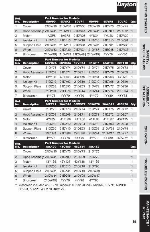
REPAIR PARTS LIST FOR ROOF-MOUNT VENTILATORS
2
5
4
6
7(Optional Accessory,
Included onUL-705 Models)
1
3
REPAIR PARTS ILLUSTRATION FOR ROOF-MOUNT VENTILATORS
465516_CenDDUpblast V3_EN_ES_FR.indd 18 10/28/2015 4:13:11 PM
19
GETTIN
G STA
RTED
SAFETY /
SPECIFIC
ATION
SA
SSEMB
LY / IN
STALLATIO
NO
PERATIO
NTR
OU
BLESH
OO
TING
MA
INTEN
AN
CE /
REPA
IR
Ref. No. Description
Part Number for Models: Qty.5DVP0 5DVP2 5DVP4 5DVP6 5DVP8 5DVR0
1 Cover 21DW30 21DW30 21DW30 21DW30 21DY73 21DY75 12 Hood Assembly 21DW41 21DW41 21DW41 21DW41 21DZ09 21DZ72 13 Motor 1AGF8 1AGF8 21DW28 4YU34 4YU28 21DW29 14 Isolator Kit 21DZ10 21DZ10 21DZ10 21DZ10 21DZ10 21DV98 15 Support Plate 21DW31 21DW31 21DW31 21DW31 21DZ31 21DW38 16 Wheel 21DW33 21DP30 21DW34 21DY87 21EC48 21DW37 17 Birdscreen 21DW49† 21DW49 21DW49† 21DW49† 4YY78 4YY80 1
Ref. No. Description
Part Number for Models: Qty.5DVR2A 5DVR3A 5DVR4A 6KWH7 6KWH8 20FT10
1 Cover 21DY73 21DY74 21DY74 21DY74 21DY75 21DY73 12 Hood Assembly 21DZ09 21DZ71 21DZ71 21DZ05 21DV76 21DZ09 13 Motor 43Y136 43Y138 43Y138 21DV61 21DV66 4YU23 14 Isolator Kit 21DZ10 21DY93 21DZ10 21DZ10 21DV98 21DZ10 15 Support Plate 21DZ33 21DZ53 21DZ53 21DV79 21DV77 21DZ30 16 Wheel 21DY91 29PH76 21DZ44 21DZ44 21DV74 29PH74 17 Birdscreen 4YY78 4YY79 4YY79 4YY79 4YY80 4YY78 1
Ref. No. Description
Part Number for Models: Qty.20FT11 36WG76 36WG77 36WG78 36WG79 48C178
1 Cover 21DY73 21DY73 21DY74 21DY74 21DY75 21DY72 1
2 Hood Assembly 21DZ09 21DZ09 21DZ71 21DZ71 21DZ72 21DZ07 13 Motor 4YU27 41TL06 41TL06 41TL06 41TL07 43Y135 14 Isolator Kit 21DZ10 21DZ10 21DY93 21DZ10 21DY93 21DZ08 15 Support Plate 21DZ30 21DY10 21DZ53 21DZ53 21DW38 21DY78 16 Wheel 29PH74 21DY09 29PH76 21DZ44 21DW17 21DY77 17 Birdscreen 4YY78 4YY78 4YY79 4YY79 4YY80 4ZA27† 1
Ref. No. Description
Part Number for Models: Qty.48C179 48C180 48C181 48C182
1 Cover 21DW30 21DY73 21DY73 21DY75 1
2 Hood Assembly 21DW41 21DZ09 21DZ09 21DZ72 13 Motor 43Y135 43Y137 43Y138 43Y139 14 Isolator Kit 21DZ08 21DZ10 21DZ10 21DY93 15 Support Plate 21DW31 21DZ31 21DY10 21DW38 16 Wheel 21DW34 21EC48 21DY09 21DW17 17 Birdscreen 21DW49† 4YY78 4YY78 4YY80 1† Birdscreen included on UL-705 models: 4HZ32, 4HZ33, 5DVN6, 5DVN8, 5DVP0,
5DVP4, 5DVP6, 48C178, 48C179.
465516_CenDDUpblast V3_EN_ES_FR.indd 19 10/28/2015 4:13:11 PM
For Repair Parts, call 1-800-Grainger24 hours a day – 365 days a year
Please provide following information:-Model number-Serial number (if any)-Part description and number as shown in parts list
MA
INTE
NA
NC
E /
REP
AIR
TRO
UB
LESH
OO
TIN
GO
PER
ATIO
NA
SSEM
BLY
/ IN
STA
LLAT
ION
SAFE
TY /
SPEC
IFIC
ATIO
NS
GET
TIN
G S
TAR
TED
20
1
2
3
4
6
7(Optional Accessory,
Included on UL-705 Models)
5
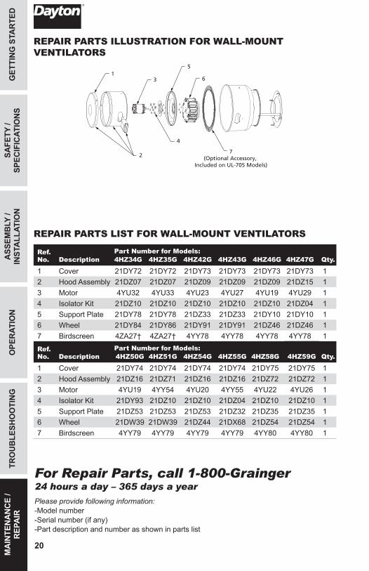
Ref. No. Description
Part Number for Models: Qty.4HZ34G 4HZ35G 4HZ42G 4HZ43G 4HZ46G 4HZ47G
1 Cover 21DY72 21DY72 21DY73 21DY73 21DY73 21DY73 12 Hood Assembly 21DZ07 21DZ07 21DZ09 21DZ09 21DZ09 21DZ15 13 Motor 4YU32 4YU33 4YU23 4YU27 4YU19 4YU29 14 Isolator Kit 21DZ10 21DZ10 21DZ10 21DZ10 21DZ10 21DZ04 15 Support Plate 21DY78 21DY78 21DZ33 21DZ33 21DY10 21DY10 16 Wheel 21DY84 21DY86 21DY91 21DY91 21DZ46 21DZ46 17 Birdscreen 4ZA27† 4ZA27† 4YY78 4YY78 4YY78 4YY78 1
Ref. No. Description
Part Number for Models: Qty.4HZ50G 4HZ51G 4HZ54G 4HZ55G 4HZ58G 4HZ59G
1 Cover 21DY74 21DY74 21DY74 21DY74 21DY75 21DY75 12 Hood Assembly 21DZ16 21DZ71 21DZ16 21DZ16 21DZ72 21DZ72 13 Motor 4YU19 4YY54 4YU20 4YY55 4YU22 4YU26 14 Isolator Kit 21DY93 21DZ10 21DZ10 21DZ04 21DZ10 21DZ10 15 Support Plate 21DZ53 21DZ53 21DZ53 21DZ32 21DZ35 21DZ35 16 Wheel 21DW39 21DW39 21DZ44 21DX68 21DZ54 21DZ54 17 Birdscreen 4YY79 4YY79 4YY79 4YY79 4YY80 4YY80 1
REPAIR PARTS LIST FOR WALL-MOUNT VENTILATORS
REPAIR PARTS ILLUSTRATION FOR WALL-MOUNT VENTILATORS
465516_CenDDUpblast V3_EN_ES_FR.indd 20 10/28/2015 4:13:12 PM
21
GETTIN
G STA
RTED
SAFETY /
SPECIFIC
ATION
SA
SSEMB
LY / IN
STALLATIO
NO
PERATIO
NTR
OU
BLESH
OO
TING
MA
INTEN
AN
CE /
REPA
IR
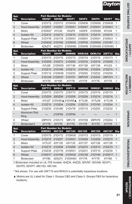
Ref. No. Description
Part Number for Models: Qty.5DVN7 5DVN9 5DVP1 5DVP3 5DVP5 5DVP7
1 Cover 21DY72 21DY72 21DW30 21DW30 21DW30 21DW30 12 Hood Assembly 21DZ07 21DZ07 21DW41 21DW41 21DW41 21DW41 13 Motor 21DW27 4YU32 1AGF8 1AGF8 21DW28 4YU34 14 Isolator Kit 21DZ10 21DZ10 21DZ10 21DZ10 21DZ10 21DZ10 15 Support Plate 21DY78 21DY78 21DW31 21DW31 21DW31 21DW31 16 Wheel 21DW32 21DY85 21DW33 21DP30 21DW34 21DY87 17 Birdscreen 4ZA27† 4AZ27† 21DW49† 21DW49 21DW49† 21DW49† 1
Ref. No. Description
Part Number for Models: Qty.5DVP9 5DVR1 6KWH9A 6KWJ0A 6KWJ1A 20FT12
1 Cover 21DY73 21DY75 21DY73 21DY74 21DY74 21DY73 12 Hood Assembly 21DZ09 21DZ72 21DZ09 21DZ16 21DZ16 21DZ09 13 Motor 4YU28 21DW29 43Y136 43Y138 43Y138 4YU23 14 Isolator Kit 21DZ10 21DV98 21DZ10 21DY93 21DZ04 21DZ10 15 Support Plate 21DY10 21DW38 21DZ33 21DZ53 21DZ32 21DZ30 16 Wheel 21EC48 21DW37 21DY91 29PH76 21DZ44 29PH74 17 Birdscreen 4YY78 4YY80 4YY78 4YY79 4YY79 4YY78 1
Ref. No. Description
Part Number for Models: Qty.20FT13 6KWJ3 20FT15 36WG80 36WG81 36WG82
1 Cover 21DY73 21DY73 21DY73 21DY73 21DY74 21DY74 12 Hood Assembly 21DZ09 20DZ09 21DZ09 21DZ09 21DZ16 21DZ16 13 Motor 4YU27 21DV65▲21DV65▲ 41TL06 41TL06 41TL06 14 Isolator Kit 21DZ10 21DZ04 21DZ04 21DZ10 21DY93 21DZ04 15 Support Plate 21DZ30 21DV80 21DV78 21DY10 21DZ53 21DZ32 1
*Aluminum Rub Ring
— 21DP94 21DP94 — — — 1
6 Wheel 29PH74 21DV73 36FL76 21DY09 29PH76 21DZ44 17 Birdscreen† 4YY78 4YY78 4YY78 4YY78 4YY79 4YY79 1
Ref. No. Description
Part Number for Models: Qty.36WG83 48C183 48C184 48C185 48C186 48C187
1 Cover 21DY75 21DY72 21DW30 21DY73 21DY73 21DY75 12 Hood Assembly 21DZ72 21DZ07 21DW41 21DZ09 21DZ09 21DZ72 13 Motor 41TL07 43Y135 43Y135 43Y137 43Y138 43Y139 14 Isolator Kit 21DZ10 21DZ08 21DZ08 21DZ10 21DZ10 21DZ10 15 Support Plate 21DZ35 21DY78 21DW31 21DZ31 21DY10 21DZ35 16 Wheel 21DW17 21DY86 21DW34 21EC48 21DY09 21DW17 17 Birdscreen 4YY80 4ZA27† 21DW49† 4YY78 4YY78 4YY80 1† Birdscreen included on UL-705 models: 4HZ34, 4HZ35, 5DVN7, 5DVN9, 5DVP1,
5DVP5, 5DVP7, 48C183, 48C184.
* Not shown. For use with 20FT15 and 6KWJ3 in potentially hazardous locations.
▲ Motors are UL Listed for Class I, Groups C&D and Class II, Groups F&G for hazardous locations.
465516_CenDDUpblast V3_EN_ES_FR.indd 21 10/28/2015 4:13:13 PM
DAYTON ONE-YEAR LIMITED WARRANTYDAYTON ONE-YEAR LIMITED WARRANTY. All Dayton® product models covered in this manual are warranted by Dayton Electric Mfg. Co. (“Dayton”) to the original user against defects in workmanship or materials under normal use for one year after date of purchase. If the Dayton product is part of a set, only the portion that is defective is subject to this warranty. Any product or part which is determined to be defective in material or workmanship and returned to an authorized service location, as Dayton or Dayton’s designee designates, shipping costs prepaid, will be, as the exclusive remedy, repaired or replaced with a new or reconditioned product or part of equal utility or a full refund given, at Dayton’s or Dayton’s designee’s option, at no charge. For limited warranty claim procedures, see “Warranty Service” below. This warranty is void if there is evidence of misuse, mis-repair, mis-installation, abuse or alteration. This warranty does not cover normal wear and tear of Dayton products or portions of them, or products or portions of them which are consumable in normal use. This limited warranty gives purchasers specific legal rights, and you may also have other rights which vary from jurisdiction to jurisdiction.
WARRANTY DISCLAIMERS AND LIMITATIONS OF LIABILITY RELATING TO ALL CUSTOMERS FOR ALL PRODUCTS
LIMITATION OF LIABILITY. TO THE EXTENT ALLOWABLE UNDER APPLICABLE LAW, DAYTON’S LIABILITY FOR CONSEQUENTIAL AND INCIDENTAL DAMAGES IS EXPRESSLY DISCLAIMED. DAYTON’S LIABILITY IN ALL EVENTS IS LIMITED TO AND SHALL NOT EXCEED THE PURCHASE PRICE PAID.
WARRANTY DISCLAIMER. A DILIGENT EFFORT HAS BEEN MADE TO PROVIDE PRODUCT INFORMATION AND ILLUSTRATE THE PRODUCTS IN THIS LITERATURE ACCURATELY; HOWEVER, SUCH INFORMATION AND ILLUSTRATIONS ARE FOR THE SOLE PURPOSE OF IDENTIFICATION, AND DO NOT EXPRESS OR IMPLY A WARRANTY THAT THE PRODUCTS ARE MERCHANTABLE, OR FIT FOR A PARTICULAR PURPOSE, OR THAT THE PRODUCTS WILL NECESSARILY CONFORM TO THE ILLUSTRATIONS OR DESCRIPTIONS. EXCEPT AS PROVIDED BELOW, NO WARRANTY OR AFFIRMATION OF FACT, EXPRESSED OR IMPLIED, OTHER THAN AS STATED IN THE “LIMITED WARRANTY” ABOVE IS MADE OR AUTHORIZED BY DAYTON.
PRODUCT SUITABILITY. MANY JURISDICTIONS HAVE CODES AND REGULATIONS GOVERNING SALES, CONSTRUCTION, INSTALLATION, AND/OR USE OF PRODUCTS FOR CERTAIN PURPOSES, WHICH MAY VARY FROM THOSE IN NEIGHBORING AREAS. WHILE ATTEMPTS ARE MADE TO ASSURE THAT DAYTON PRODUCTS COMPLY WITH SUCH CODES, DAYTON CANNOT GUARANTEE COMPLIANCE, AND CANNOT BE RESPONSIBLE FOR HOW THE PRODUCT IS INSTALLED OR USED. BEFORE PURCHASE AND USE OF A PRODUCT, REVIEW THE SAFETY/SPECIFICATIONS, AND ALL APPLICABLE NATIONAL AND LOCAL CODES AND REGULATIONS, AND BE SURE THAT THE PRODUCT, INSTALLATION, AND USE WILL COMPLY WITH THEM.
CONSUMERS ONLY. CERTAIN ASPECTS OF DISCLAIMERS ARE NOT APPLICABLE TO CONSUMER PRODUCTS SOLD TO CONSUMERS; (A) SOME JURISDICTIONS DO NOT ALLOW THE EXCLUSION OR LIMITATION OF INCIDENTAL OR CONSEQUENTIAL DAMAGES, SO THE ABOVE LIMITATION OR EXCLUSION MAY NOT APPLY TO YOU; (B) ALSO, SOME JURISDICTIONS DO NOT ALLOW A LIMITATION ON HOW LONG AN IMPLIED WARRANTY LASTS, SO THE ABOVE LIMITATION MAY NOT APPLY TO YOU; AND (C) BY LAW, DURING THE PERIOD OF THIS LIMITED WARRANTY, ANY IMPLIED WARRANTIES OF MERCHANTABILITY OR FITNESS FOR A PARTICULAR PURPOSE APPLICABLE TO CONSUMER PRODUCTS PURCHASED BY CONSUMERS, MAY NOT BE EXCLUDED OR OTHERWISE DISCLAIMED.
THIS LIMITED WARRANTY ONLY APPLIES TO UNITED STATES PURCHASERS FOR DELIVERY IN THE UNITED STATES.
WARRANTY SERVICE
To obtain warranty service if you purchased the covered product directly from W.W. Grainger, Inc. (“Grainger”), (i) write or call or visit the local Grainger branch from which the product was purchased or another Grainger branch near you (see www.grainger.com for a listing of Grainger branches); or (ii) contact Grainger by going to www.grainger.com and clicking on the “Contact Us” link at the top of the page, then clicking on the “Email us” link; or (iii) call Customer Care (toll free) at 1-888-361-8649. To obtain warranty service if you purchased the covered product from another distributor or retailer, (i) go to www.grainger.com for Warranty Service; (ii) write or call or visit a Grainger branch near you; or (iii) call Customer Care (toll free) at 1-888-361-8649. In any case, you will need to provide, to the extent available, the purchase date, the original invoice number, the stock number, a description of the defect, and anything else specified in this Dayton One-Year Limited Warranty. You may be required to send the product in for inspection at your cost. You can follow up on the progress of inspections and corrections in the same ways. Title and risk of loss pass to buyer on delivery to common carrier, so if product was damaged in transit to you, file claim with carrier, not retailer, Grainger or Dayton. For warranty information for purchasers and/or delivery outside the United States, please use the following applicable contact information:
Dayton Electric Mfg. Co., 100 Grainger Parkway, Lake Forest, IL 60045 U.S.A. or call +1-888-361-8649
DM_US 44930530-6.019350.0029
465516_CenDDUpblast V3_EN_ES_FR.indd 22 10/28/2015 4:13:13 PM


![Index [ ] · PDF fileIndex Page Roof-Exhaust-Centrifugal-Aluminum Direct Drive Mushroom Style TKS 3 Direct Drive Mushroom Style DR 4 Direct Drive Upblast DU 5 Belt Drive Mushroom](https://static.fdocuments.in/doc/165x107/5abc74437f8b9a321b8e0c7c/index-page-roof-exhaust-centrifugal-aluminum-direct-drive-mushroom-style-tks.jpg)


