
CENTRIFUGAL FANS, BLOWERS AND COMPRESSORS · In general the centrifugal compressor may be known as...
28
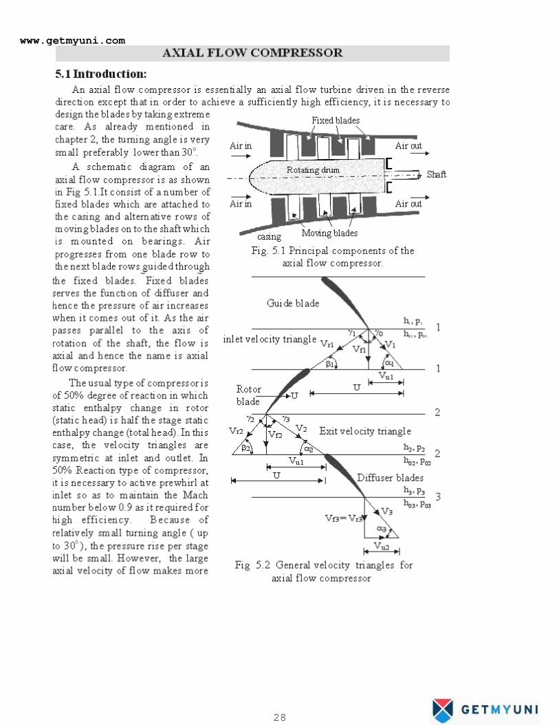
CENTRIFUGAL FANS, BLOWERS AND COMPRESSORS 4.1 Introduction Power absorbing turbomachines used to handle compressible fluids like air, gases etc, can be broadly classified into: (i) Fans (ii)Blowers and (iii)Compressors. These machines produce the head (pressure) in the expense of mechanical energy input. The pressure rise in centrifugal type machines are purely due to the centrifugal effects. A fan usually consists of a single rotor with or without a stator. It causes only a small pressure rise as low as a few centimeters of water column. Generally it rises the pressure upto a maximum of 0.07 bar (70 cm WG). In the analysis of the fan, the fluid will be treated as incompressible as the density change is very small due to small pressure rise. Fans are used for air circulation in buildings, for ventilation, in automobiles in front of engine for cooling purposes etc. Blower may consists of one or more stages of compression with its rotors mounted on a common shaft. The air is compressed in a series of successive stages and is passed through a diffuser located near the exit to recover the pressure energy from the large kinetic energy. The overall pressure rise may be in the range of 1.5 to 2.5 bars. Blowers are used in ventilation, power station, workshops etc. Compressor is used to produce large pressure rise ranging from 2.5 to 10 bar or more. A single stage compressor can generally produce a pressure rise up to 4 bar. Since the velocities of air flow are quite high, the Mach number and compressibility effects may have to be taken into account in evaluating the stage performance of a compressor. In general the centrifugal compressor may be known as a fan, blower, supercharger etc, depending on the need to be served. Broadly speaking, fans are the low-pressure compressors; blowers are the medium pressure compressors. It is therefore the analysis of one, say centrifugal compressor, will also holds good to the other machines like blower, fans. 4.2 Important Elements of a Centrifugal Compressor Fig.4.1 shows the essential parts of a typical centrifugal compressor. It mainly consists of (i) inlet casing with the converging nozzle (ii) the impeller (iii) the diffuser and (iv) the outlet casing. The function of the inlet casing with the conversant nozzle is to accelerate the entering fluid to the impeller inlet. The inlet nozzle accelerate the fluid from the initial condition (state 0 ) to the entry of the Inlet Guide Vanes (IGV) which direct the flow in the desired direction at the inlet of the impeller (state 1). The impeller convert the supplied mechanical energy into fluid energy whereby the fluid kinetic energy and the static pressure rises. An impeller is made of radial blades which are brazed to the shroud. It can be made from a single piece consisting of both the inducer and a largely radial portion. The inducer receives the flow between the hub and tip diameters (dh and dt ) of the impeller eye and passes on to the radial portion of the impeller blades. The flow approaching the impeller may be with or without swirl. The inlet diameter 4.2 Important Elements of a Centrifugal Compressor Fig.4.1 shows the essential parts of a typical centrifugal compressor. It mainly consists of (i) inlet casing with the converging nozzle (ii) the impeller (iii) the diffuser and (iv) the outlet casing. www.getmyuni.com 1
Transcript of CENTRIFUGAL FANS, BLOWERS AND COMPRESSORS · In general the centrifugal compressor may be known as...
CENTRIFUGAL FANS, BLOWERS AND COMPRESSORS 4.1 Introduction
Power absorbing turbomachines used to handle compressible fluids like air, gases etc,
can be broadly classified into: (i) Fans (ii)Blowers and (iii)Compressors. These machines
produce the head (pressure) in the expense of mechanical energy input. The pressure rise in
centrifugal type machines are purely due to the centrifugal effects.
A fan usually consists of a single rotor with or without a stator. It causes only a small
pressure rise as low as a few centimeters of water column. Generally it rises the pressure upto a
maximum of 0.07 bar (70 cm WG). In the analysis of the fan, the fluid will be treated as
incompressible as the density change is very small due to small pressure rise. Fans are used for
air circulation in buildings, for ventilation, in automobiles in front of engine for cooling purposes
etc.
Blower may consists of one or more stages of compression with its rotors mounted on a
common shaft. The air is compressed in a series of successive stages and is passed through a
diffuser located near the exit to recover the pressure energy from the large kinetic energy. The
overall pressure rise may be in the range of 1.5 to 2.5 bars. Blowers are used in ventilation,
power station, workshops etc.
Compressor is used to produce large pressure rise ranging from 2.5 to 10 bar or more. A
single stage compressor can generally produce a pressure rise up to 4 bar. Since the velocities of
air flow are quite high, the Mach number and compressibility effects may have to be taken into
account in evaluating the stage performance of a compressor.
In general the centrifugal compressor may be known as a fan, blower, supercharger etc,
depending on the need to be served. Broadly speaking, fans are the low-pressure compressors;
blowers are the medium pressure compressors. It is therefore the analysis of one, say centrifugal
compressor, will also holds good to the other machines like blower, fans.
4.2 Important Elements of a Centrifugal Compressor
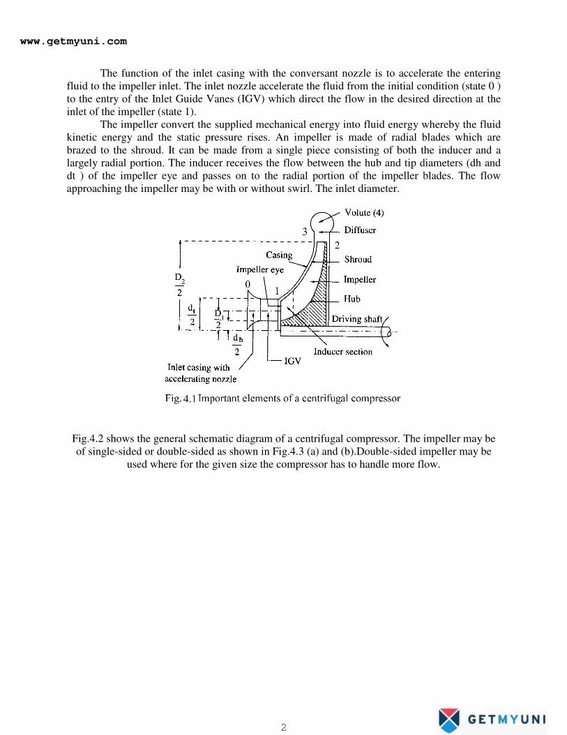
Fig.4.1 shows the essential parts of a typical centrifugal compressor. It mainly consists of
(i) inlet casing with the converging nozzle (ii) the impeller (iii) the diffuser and (iv) the outlet
casing.
The function of the inlet casing with the conversant nozzle is to accelerate the entering
fluid to the impeller inlet. The inlet nozzle accelerate the fluid from the initial condition (state 0 )
to the entry of the Inlet Guide Vanes (IGV) which direct the flow in the desired direction at the
inlet of the impeller (state 1).
The impeller convert the supplied mechanical energy into fluid energy whereby the fluid
kinetic energy and the static pressure rises. An impeller is made of radial blades which are
brazed to the shroud. It can be made from a single piece consisting of both the inducer and a
largely radial portion. The inducer receives the flow between the hub and tip diameters (dh and
dt ) of the impeller eye and passes on to the radial portion of the impeller blades. The flow
approaching the impeller may be with or without swirl. The inlet diameter 4.2 Important
Elements of a Centrifugal Compressor
Fig.4.1 shows the essential parts of a typical centrifugal compressor. It mainly consists of
(i) inlet casing with the converging nozzle (ii) the impeller (iii) the diffuser and (iv) the outlet
casing.
www.getmyuni.com
1
The function of the inlet casing with the conversant nozzle is to accelerate the entering
fluid to the impeller inlet. The inlet nozzle accelerate the fluid from the initial condition (state 0 )
to the entry of the Inlet Guide Vanes (IGV) which direct the flow in the desired direction at the
inlet of the impeller (state 1).
The impeller convert the supplied mechanical energy into fluid energy whereby the fluid
kinetic energy and the static pressure rises. An impel
brazed to the shroud. It can be made from a single piece consisting of both the inducer and a
largely radial portion. The inducer receives the flow between the hub and tip diameters (dh and
dt ) of the impeller eye and passes on to the radial portion of the impeller blades. The flow
approaching the impeller may be with or without swirl. The inlet diameter.
Fig.4.2 shows the general schematic diagram of a centrifugal compressor. The impeller may be
of single-sided or double-sided as shown in Fig.4.3 (a) and (b).Double
used where for the given size the compressor has to handle more flow.
The function of the inlet casing with the conversant nozzle is to accelerate the entering
fluid to the impeller inlet. The inlet nozzle accelerate the fluid from the initial condition (state 0 )
e Inlet Guide Vanes (IGV) which direct the flow in the desired direction at the
The impeller convert the supplied mechanical energy into fluid energy whereby the fluid
kinetic energy and the static pressure rises. An impeller is made of radial blades which are
brazed to the shroud. It can be made from a single piece consisting of both the inducer and a
largely radial portion. The inducer receives the flow between the hub and tip diameters (dh and
d passes on to the radial portion of the impeller blades. The flow
approaching the impeller may be with or without swirl. The inlet diameter.
Fig.4.2 shows the general schematic diagram of a centrifugal compressor. The impeller may be
sided as shown in Fig.4.3 (a) and (b).Double-sided impeller may be
used where for the given size the compressor has to handle more flow.
The function of the inlet casing with the conversant nozzle is to accelerate the entering
fluid to the impeller inlet. The inlet nozzle accelerate the fluid from the initial condition (state 0 )
e Inlet Guide Vanes (IGV) which direct the flow in the desired direction at the
The impeller convert the supplied mechanical energy into fluid energy whereby the fluid
ler is made of radial blades which are
brazed to the shroud. It can be made from a single piece consisting of both the inducer and a
largely radial portion. The inducer receives the flow between the hub and tip diameters (dh and
d passes on to the radial portion of the impeller blades. The flow
Fig.4.2 shows the general schematic diagram of a centrifugal compressor. The impeller may be
sided impeller may be
used where for the given size the compressor has to handle more flow.
www.getmyuni.com
2
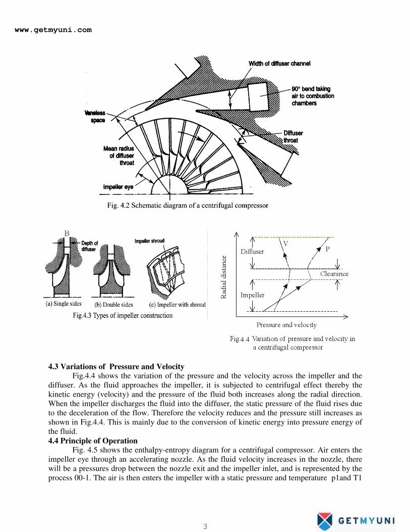
4.3 Variations of Pressure and Velocity
Fig.4.4 shows the variation of the pressure and the
diffuser. As the fluid approaches the impeller, it is subjected to centrifugal effect thereby the
kinetic energy (velocity) and the pressure of the fluid both increases along the radial direction.
When the impeller discharges the fluid into the diffuser, the static pressure of the fluid rises due
to the deceleration of the flow. Therefore the velocity reduces and the pressure still increases as
shown in Fig.4.4. This is mainly due to the conversion of kinetic energy into
the fluid.
4.4 Principle of Operation
Fig. 4.5 shows the enthalpy
impeller eye through an accelerating nozzle. As the fluid velocity increases in the nozzle, there
will be a pressures drop between the nozzle exit and the impeller inlet, and is represented by the
process 00-1. The air is then enters the impeller with a static pressure and temperature p1and T1
4.3 Variations of Pressure and Velocity
Fig.4.4 shows the variation of the pressure and the velocity across the impeller and the
diffuser. As the fluid approaches the impeller, it is subjected to centrifugal effect thereby the
kinetic energy (velocity) and the pressure of the fluid both increases along the radial direction.
harges the fluid into the diffuser, the static pressure of the fluid rises due
to the deceleration of the flow. Therefore the velocity reduces and the pressure still increases as
shown in Fig.4.4. This is mainly due to the conversion of kinetic energy into pressure energy of
Fig. 4.5 shows the enthalpy-entropy diagram for a centrifugal compressor. Air enters the
impeller eye through an accelerating nozzle. As the fluid velocity increases in the nozzle, there
pressures drop between the nozzle exit and the impeller inlet, and is represented by the
1. The air is then enters the impeller with a static pressure and temperature p1and T1
velocity across the impeller and the
diffuser. As the fluid approaches the impeller, it is subjected to centrifugal effect thereby the
kinetic energy (velocity) and the pressure of the fluid both increases along the radial direction.
harges the fluid into the diffuser, the static pressure of the fluid rises due
to the deceleration of the flow. Therefore the velocity reduces and the pressure still increases as
pressure energy of
entropy diagram for a centrifugal compressor. Air enters the
impeller eye through an accelerating nozzle. As the fluid velocity increases in the nozzle, there
pressures drop between the nozzle exit and the impeller inlet, and is represented by the
1. The air is then enters the impeller with a static pressure and temperature p1and T1
www.getmyuni.com
3
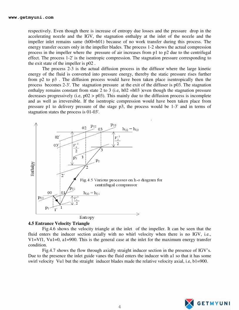
respectively. Even though there is increase of entropy due losses and the pressure drop in the
accelerating nozzle and the IGV, the stagnation enthalpy at the inlet of the nozzle and the
impeller inlet remains same (h00=h01) because of no work transfer during this process. The
energy transfer occurs only in the impeller blades. The process 1-2 shows the actual compression
process in the impeller where the pressure of air increases from p1 to p2 due to the centrifugal
effect. The process 1-2' is the isentropic compression. The stagnation pressure corresponding to
the exit state of the impeller is p02 .
The process 2-3 is the actual diffusion process in the diffusor where the large kinetic
energy of the fluid is converted into pressure energy, thereby the static pressure rises further
from p2 to p3 . The diffusion process would have been taken place isentropically then the
process becomes 2-3'. The stagnation pressure at the exit of the diffuser is p03. The stagnation
enthalpy remains constant from state 2 to 3 (i.e, h02 =h03 )even though the stagnation pressure
decreases progressively (i.e, p02 > p03). This mainly due to the diffusion process is incomplete
and as well as irreversible. If the isentropic compression would have been taken place from
pressure p1 to delivery pressure of the stage p3, the process would be 1-3' and in terms of
stagnation states the process is 01-03'.
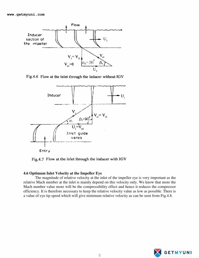
4.5 Entrance Velocity Triangle
Fig.4.6 shows the velocity triangle at the inlet of the impeller. It can be seen that the
fluid enters the inducer section axially with no whirl velocity when there is no IGV, i.e.,
V1=Vf1, Vu1=0, a1=900. This is the general case at the inlet for the maximum energy transfer
condition.
Fig.4.7 shows the flow through axially straight inducer section in the presence of IGV’s.
Due to the presence the inlet guide vanes the fluid enters the inducer with a1 so that it has some
swirl velocity Vu1 but the straight inducer blades made the relative velocity axial, i.e, b1=900.
www.getmyuni.com
4
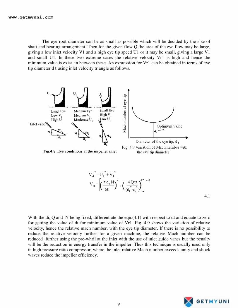
4.6 Optimum Inlet Velocity at the Impeller Eye
The magnitude of relative velocity at the inlet of the impeller eye is very important as the
relative Mach number at the inlet is mainly depend on this velocity only. We know that more the
Mach number value more will be the compressibility effect and hence it reduces the compressor
efficiency. It is therefore necessary to keep the relative velocity value as low as possible. There is
a value of eye tip speed which will give minimum relative velocity as can be seen from Fig.4.8.
www.getmyuni.com
5
The eye root diameter can be as small as possible which will b
shaft and bearing arrangement. Then for the given flow Q the area of the eye flow may be large,
giving a low inlet velocity V1 and a high eye tip speed U1 or it may be small, giving a large V1
and small U1. In these two extreme cas
minimum value is exist in between these. An expression for Vr1 can be obtained in terms of eye
tip diameter d t using inlet velocity triangle as follows.
With the di, Q and N being fixed, differentiate the eqn.(4.1) with respect to dt and equate to zero
for getting the value of dt for minimum value of Vr1. Fig. 4.9 shows the variation of relative
velocity, hence the relative mach number, with the eye tip diameter. If
reduce the relative velocity further for a given machine, the relative Mach number can be
reduced further using the pre-whril at the inlet with the use of inlet guide vanes but the penalty
will be the reduction in energy transf
in high pressure ratio compressor, where the inlet relative Mach number exceeds unity and shock
waves reduce the impeller efficiency.
The eye root diameter can be as small as possible which will be decided by the size of
shaft and bearing arrangement. Then for the given flow Q the area of the eye flow may be large,
giving a low inlet velocity V1 and a high eye tip speed U1 or it may be small, giving a large V1
and small U1. In these two extreme cases the relative velocity Vr1 is high and hence the
minimum value is exist in between these. An expression for Vr1 can be obtained in terms of eye
tip diameter d t using inlet velocity triangle as follows.
, Q and N being fixed, differentiate the eqn.(4.1) with respect to dt and equate to zero
for getting the value of dt for minimum value of Vr1. Fig. 4.9 shows the variation of relative
velocity, hence the relative mach number, with the eye tip diameter. If there is no possibility to
reduce the relative velocity further for a given machine, the relative Mach number can be
whril at the inlet with the use of inlet guide vanes but the penalty
will be the reduction in energy transfer in the impeller. Thus this technique is usually used only
in high pressure ratio compressor, where the inlet relative Mach number exceeds unity and shock
waves reduce the impeller efficiency.
e decided by the size of
shaft and bearing arrangement. Then for the given flow Q the area of the eye flow may be large,
giving a low inlet velocity V1 and a high eye tip speed U1 or it may be small, giving a large V1
es the relative velocity Vr1 is high and hence the
minimum value is exist in between these. An expression for Vr1 can be obtained in terms of eye
4.1
, Q and N being fixed, differentiate the eqn.(4.1) with respect to dt and equate to zero
for getting the value of dt for minimum value of Vr1. Fig. 4.9 shows the variation of relative
there is no possibility to
reduce the relative velocity further for a given machine, the relative Mach number can be
whril at the inlet with the use of inlet guide vanes but the penalty
er in the impeller. Thus this technique is usually used only
in high pressure ratio compressor, where the inlet relative Mach number exceeds unity and shock
www.getmyuni.com
6
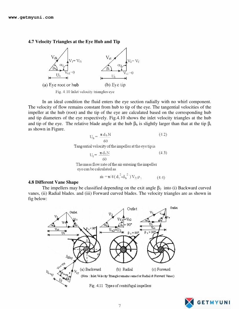
4.7 Velocity Triangles at the Eye Hub and Tip
In an ideal condition the fluid enters the eye section radially with no whirl component.
The velocity of flow remains constant from hub to tip of the eye. The tangential velocities of the
impeller at the hub (root) and the tip of the eye are calculated based on the corresponding hub
and tip diameters of the eye respectively. Fig.4.10 shows the inlet velocity triangles at the hub
and tip of the eye. The relative blade angle at the hub βh is slightly larger than that at the tip βt
as shown in Figure.
4.8 Different Vane Shape
The impellers may be classified depending on the exit angle β2 into (i) Backward curved
vanes, (ii) Radial blades. and (iii) Forward curved blades. The velocity triangles are as shown in
fig below:
www.getmyuni.com
7
Backward curved blades are those which make an angle less than 90 o
((β2 <90 o
)at the exit of
the impeller with respect to the tangential direction, radial blades will make an angle of 90 o
(β2 =
90 o
)and the forward curved blades will make an angle more than 90o
((β2 >90 o
)as shown in
Fig.4.11.
In centrifugal compressors generally radial blades are used but the backward curved
vanes are also used more often in practice for special purposes. Forward curved vanes are rarely
used.
4.9 Degree of Reaction (R)
The degree of reaction (R) for the radial flow power absorbing machines is already
discussed in chapter-2 and hence from eqn.(2.55) it is given by
The above equation can also be expressed using velocity triangles as
Since it is assumed that the flow velocity is constant through out, i.e, Vf1= Vf2, the degree of
reaction can be expressed as
4.10 Effects of Exit Blade Angle
The effect of vane shape on its efficiency can be studied by considering the constant
value of tangential tip speed (U2) and constant radial velocity of flow (Vf2)
When β2 < 90o as in Fig 4.11(a), the value of V2 will be low and its tangential component
(Vu2) also low. Hence the absolute velocity of air at exit of the impeller is less and therefore the
losses at exit are reduced to get high pressure rise. Thus, the efficiency of the backward curved
vanes are considerably high and the losses are less.
When β2 = 90o , Fig 4.11(b), the value of V2 will more or moderate and V2 is also
slightly high. Correspondingly, exit velocity of air V2 will have a slightly higher value and hence
losses at exit is slightly high for this type machine. Therefore, in the radial vanes impeller, the
efficiency is moderate and the losses are also moderate.
www.getmyuni.com
8
When β2 > 90o , Fig.4.11(c), the value of V2 will be very more and correspondingly the
loss at the exit is much more. Consequently , an extremely well efficient diffuser has to be used
to recover the pressure energy from the large kinetic energy at the exit. But due to high
turbulence and thick boundary layers a complete conversion of kinetic energy for the
corresponding pressure rise is impossible in the diffuser. Hence the forward curved vanes are
unstable and less efficient. They need more input energy to operate.
Therefore from the above discussion it can be concluded that the impeller with large exit
blade angles are less efficient than that of the impeller with smaller exit angles. Thus the
backward vanes are used where high efficiency is desired and the radial blades are used when
the high pressure rise is needed though the efficiency is not high. Forward curved blades are
used very rarely. Generally the centrifugal compressor impellers are of radial type because of
their easy manufacture and suitable for high speed.
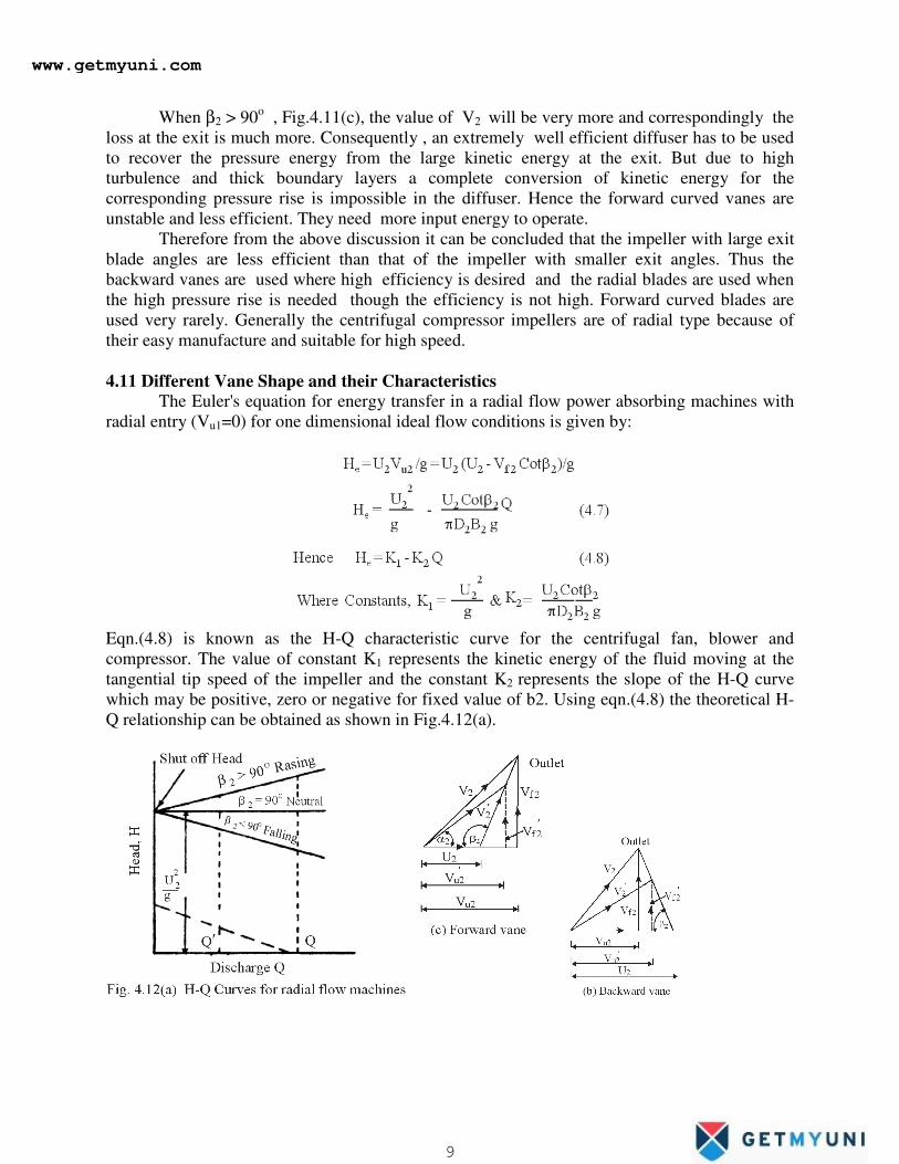
4.11 Different Vane Shape and their Characteristics
The Euler's equation for energy transfer in a radial flow power absorbing machines with
radial entry (Vu1=0) for one dimensional ideal flow conditions is given by:
Eqn.(4.8) is known as the H-Q characteristic curve for the centrifugal fan, blower and
compressor. The value of constant K1 represents the kinetic energy of the fluid moving at the
tangential tip speed of the impeller and the constant K2 represents the slope of the H-Q curve
which may be positive, zero or negative for fixed value of b2. Using eqn.(4.8) the theoretical H-
Q relationship can be obtained as shown in Fig.4.12(a).
www.getmyuni.com
9
In backward curved blades, i.e., β2 < 90o, the value of Cot β2 is positive, hence such type
machine has a negative slope (i.e.,K2 is positive) & therefore H-Q curves is falling type as shown
in Fig.4.12(a). In backward curved blades as the discharge increases, the head or the total
enthalpy rise, ∆h0, reduces as Vu2 decreases for a given value of β2 as can be seen in Fig.(b).
The dashed line shows the initial value of flow, and the solid line represents the velocity triangle
for a increased flow.
In radial blades i.e., β2 =90o, the value of Cot β2 is Zero. For such type of machine for
any value of flow rates , the head remains constant as shown in Fig.4.12(a).
In forward curved blade, i.e., β2 > 90o , the value of Cot β2 is negative, and H-Q curve
has a positive slope as shown in Fig.4.12(a). Hence for increased discharge, head also increases
as Vu2 increases for a given β2 as shown in Fig.4.12(c)and it has rising characteristics.
In eqn. (4.8), if Q=0, He=Hs = U22/g. This head which is independent of vane shape is
called “Shut-off head ”. The actual measured head at shut-off is much less than the value
of (U22/g) due to high turbulence and shock when pre-whirl exist as shown in inclined dash line
as in Fig.4.12(a).
From Fig.4.12(b), it seen that for large value of β2 , the value of V2 also more. For
backward curved vanes, the value of Vu2 is less and hence energy transfer is less, but losses at
exit is also less for forward curved vanes, Vu2 is large, hence it transfer more energy but as the
value of V2 is more, the losses cannot be diffused in a fixed casing.
Hence backward curved vanes are generally used. The radial vanes are used for high
pressure rise and are a reasonable compromise between high exit K.E. and high energy transfer,
and also easy to design.
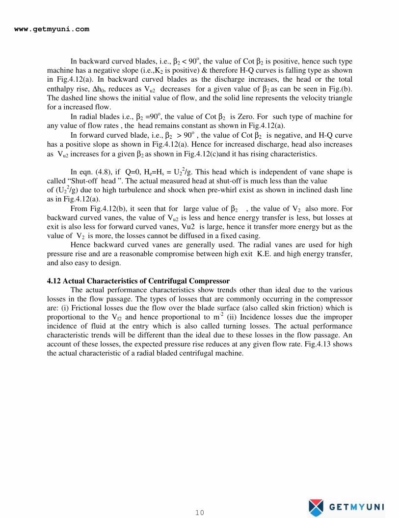
4.12 Actual Characteristics of Centrifugal Compressor
The actual performance characteristics show trends other than ideal due to the various
losses in the flow passage. The types of losses that are commonly occurring in the compressor
are: (i) Frictional losses due the flow over the blade surface (also called skin friction) which is
proportional to the Vf2 and hence proportional to m·2
(ii) Incidence losses due the improper
incidence of fluid at the entry which is also called turning losses. The actual performance
characteristic trends will be different than the ideal due to these losses in the flow passage. An
account of these losses, the expected pressure rise reduces at any given flow rate. Fig.4.13 shows
the actual characteristic of a radial bladed centrifugal machine.
www.getmyuni.com
10
Actual head produced can therefore be obtained by deducting these losses from ideal (Euler’s)
head
developed by the machine, i.e.,
H=He- hf (4.12)
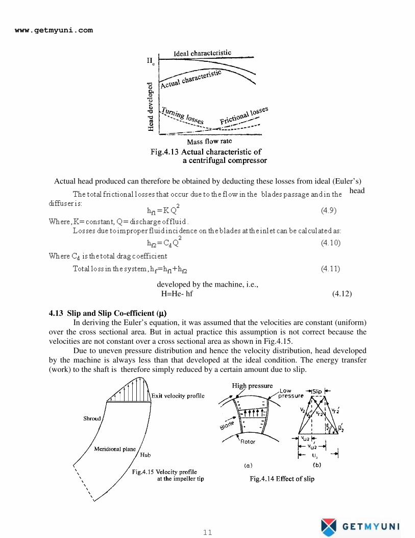
4.13 Slip and Slip Co-efficient (µ)µ)µ)µ) In deriving the Euler’s equation, it was assumed that the velocities are constant (uniform)
over the cross sectional area. But in actual practice this assumption is not correct because the
velocities are not constant over a cross sectional area as shown in Fig.4.15.
Due to uneven pressure distribution and hence the velocity distribution, head developed
by the machine is always less than that developed at the ideal condition. The energy transfer
(work) to the shaft is therefore simply reduced by a certain amount due to slip.
www.getmyuni.com
11
The general Euler’s energy transfer without slip is given by
Ee = ( U2 Vu2 - U1 Vu1 )/gc
For ideal condition at inlet the fluid enters radially with no whirl component, the
energy equation becomes
Ee = U2 Vu2 / gc
For the maximum energy transfer the blades are assumed to be radial, i.e, U2 = Vu2,
hence the energy becomes
Ee,max = U22
/ gc
Now the ideal energy transfer with slip, using eqn.(4.14), is
E =m U22 / gc (4.15)
Eqn.(4.15) represents the theoretical or maximum work done on the air.
In Fig.4.14, the components drawn with dash referred to the ideal conditions without slip
and without dash refers to a ideal condition after considering the slip and non-uniform velocity
distribution at the tip. The head based on the ideal velocity diagrams without slip is called
Euler’s head (He) and the head obtained corresponding to the slip is called ideal head (Hi) as the
fluid is ideal. The actual head developed by the machine is related to the ideal head through the
adiabatic or diagram efficiency (h) of a machine.
The difference between the Euler’s head (He) and the ideal head (Hi) is called the slip. It
can also be defined as the difference between tangential component of the velocity Vu2 and
Vu2’ . Therefore
Slip, S = V’u2 - Vu2 (4.13)
The ratio of ideal head with the slip to the Euler’s head without slip is called the slip
coefficient. Therefore the slip coefficient is given by
µ = Hi / H e = Vu2 /V’u2 (4.14)
The slip factor is a parameter which limits the work capacity of the compressor even
under ideal conditions and this quantity should be as high as possible. More the number of vanes,
greater will be the value of slip factor, but increases the solidity of the impeller eye, i.e.,a
decrease in the effective flow area. This gives an additional frictional loss at the eye which is not
recommended. It is therefore necessary to select the number of vanes in the impeller so as to give
minimum losses. Generally, in practice, 19-20 vanes will be selected so that the slip factor value
is around 0.9.
4.14 Energy Transfer
4.15
Power
Input
Factor
or
Work
dine
Factor
(ΨΨΨΨ )
In real fluid, some part of the power supplied by the impeller on the air is used to
overcome the losses like windage, disc friction and casing losses. Therefore the power required
is greater than the actual power to be supplied on the air and hence the actual power to be
supplied is taken care by the term power input factor. The power input factor is defined as the
ratio of actual work supplied to the theoretical work supplied. The power input factor or work
done factor (Ψ ) is
4.16 Overall Pressure ratio (pro)
www.getmyuni.com
12
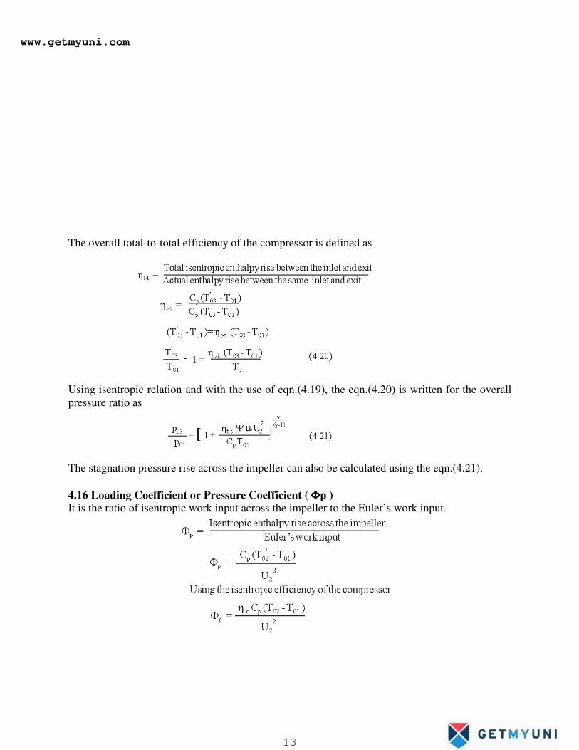
The overall total-to-total efficiency of the compressor is defined as
Using isentropic relation and with the use of eqn.(4.19), the eqn.(4.20) is written for the overall
pressure ratio as
The stagnation pressure rise across the impeller can also be calculated using the eqn.(4.21).
4.16 Loading Coefficient or Pressure Coefficient ( ΦΦΦΦp ) It is the ratio of isentropic work input across the impeller to the Euler’s work input.
www.getmyuni.com
13
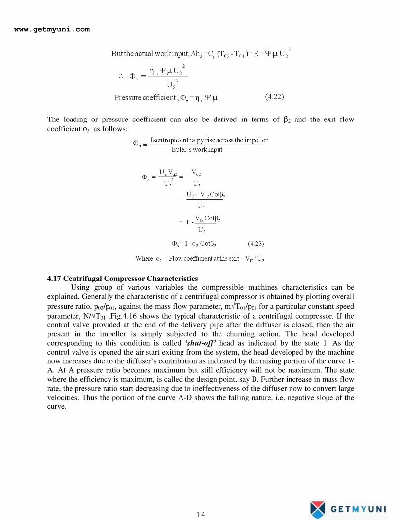
The loading or pressure coefficient can also be derived in terms of β2 and the exit flow
coefficient φ2 as follows:
4.17 Centrifugal Compressor Characteristics
Using group of various variables the compressible machines characteristics can be
explained. Generally the characteristic of a centrifugal compressor is obtained by plotting overall
pressure ratio, p03/p01, against the mass flow parameter, m√T01/p01 for a particular constant speed
parameter, N/√T01 .Fig.4.16 shows the typical characteristic of a centrifugal compressor. If the
control valve provided at the end of the delivery pipe after the diffuser is closed, then the air
present in the impeller is simply subjected to the churning action. The head developed
corresponding to this condition is called ‘shut-off’ head as indicated by the state 1. As the
control valve is opened the air start exiting from the system, the head developed by the machine
now increases due to the diffuser’s contribution as indicated by the raising portion of the curve 1-
A. At A pressure ratio becomes maximum but still efficiency will not be maximum. The state
where the efficiency is maximum, is called the design point, say B. Further increase in mass flow
rate, the pressure ratio start decreasing due to ineffectiveness of the diffuser now to convert large
velocities. Thus the portion of the curve A-D shows the falling nature, i.e, negative slope of the
curve.
www.getmyuni.com
14
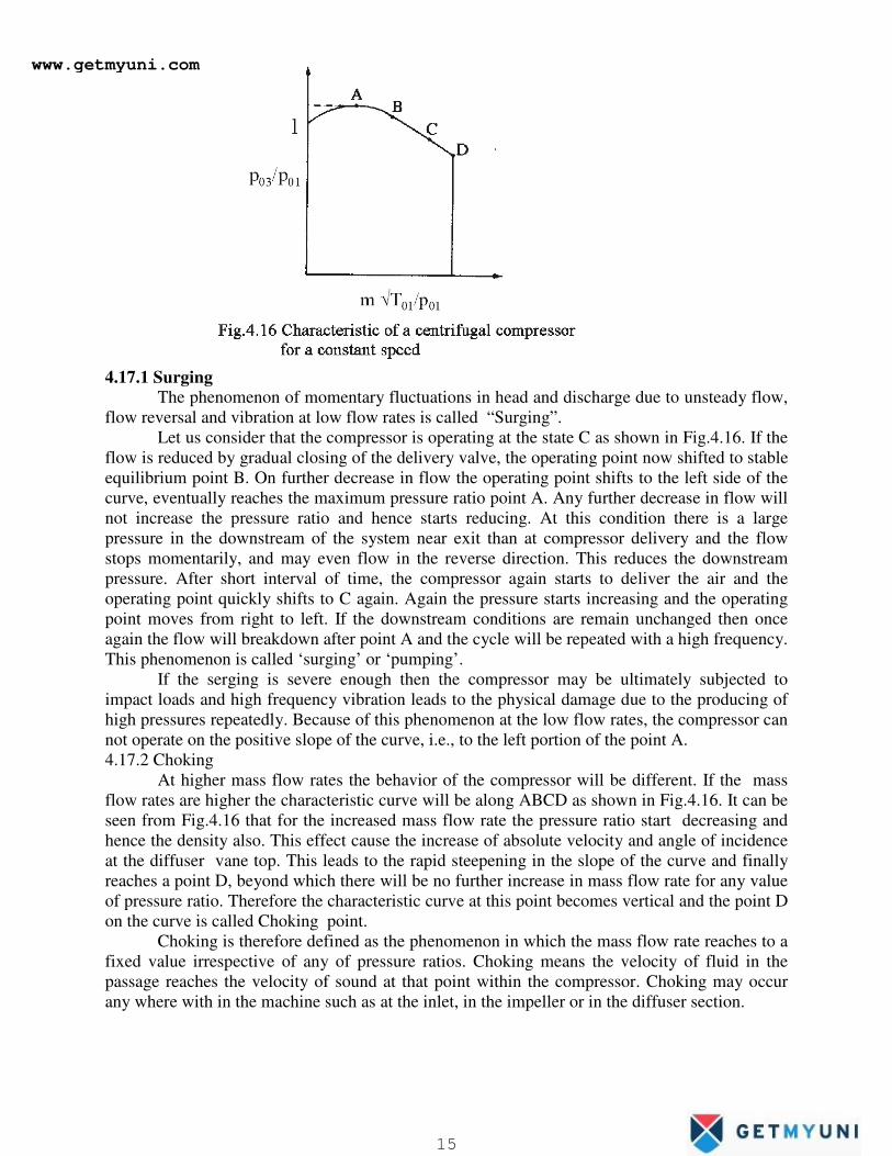
4.17.1 Surging
The phenomenon of momentary fluctuations in head and discharge due to unsteady flow,
flow reversal and vibration at low flow rates is called “Surging”.
Let us consider that the compressor is operating at the state C as shown in Fig.4.16. If the
flow is reduced by gradual closing of the delivery valve, the operating point now shifted to stable
equilibrium point B. On further decrease in flow the operating point shifts to the left side of the
curve, eventually reaches the maximum pressure ratio point A. Any further decrease in flow will
not increase the pressure ratio and hence starts reducing. At this condition there is a large
pressure in the downstream of the system near exit than at compressor delivery and the flow
stops momentarily, and may even flow in the reverse direction. This reduces the downstream
pressure. After short interval of time, the compressor again starts to deliver the air and the
operating point quickly shifts to C again. Again the pressure starts increasing and the operating
point moves from right to left. If the downstream conditions are remain unchanged then once
again the flow will breakdown after point A and the cycle will be repeated with a high frequency.
This phenomenon is called ‘surging’ or ‘pumping’.
If the serging is severe enough then the compressor may be ultimately subjected to
impact loads and high frequency vibration leads to the physical damage due to the producing of
high pressures repeatedly. Because of this phenomenon at the low flow rates, the compressor can
not operate on the positive slope of the curve, i.e., to the left portion of the point A.
4.17.2 Choking
At higher mass flow rates the behavior of the compressor will be different. If the mass
flow rates are higher the characteristic curve will be along ABCD as shown in Fig.4.16. It can be
seen from Fig.4.16 that for the increased mass flow rate the pressure ratio start decreasing and
hence the density also. This effect cause the increase of absolute velocity and angle of incidence
at the diffuser vane top. This leads to the rapid steepening in the slope of the curve and finally
reaches a point D, beyond which there will be no further increase in mass flow rate for any value
of pressure ratio. Therefore the characteristic curve at this point becomes vertical and the point D
on the curve is called Choking point.
Choking is therefore defined as the phenomenon in which the mass flow rate reaches to a
fixed value irrespective of any of pressure ratios. Choking means the velocity of fluid in the
passage reaches the velocity of sound at that point within the compressor. Choking may occur
any where with in the machine such as at the inlet, in the impeller or in the diffuser section.
www.getmyuni.com
15
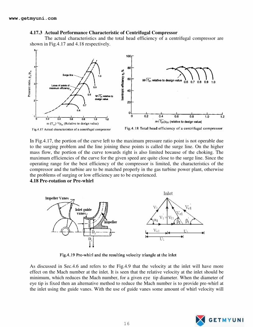
4.17.3 Actual Performance Characteristic of Centrifugal Compressor
The actual characteristics and the total head efficiency of a centrifugal compressor are
shown in Fig.4.17 and 4.18 respectively.
In Fig.4.17, the portion of the curve left to the maximum pressure ratio point is not operable due
to the surging problem and the line joining these points is called the surge line. On the higher
mass flow, the portion of the curve towards right is also limited because of the choking. The
maximum efficiencies of the curve for the given speed are quite close to the surge line. Since the
operating range for the best efficiency of the compressor is limited, the characteristics of the
compressor and the turbine are to be matched properly in the gas turbine power plant, otherwise
the problems of surging or low efficiency are to be experienced.
4.18 Pre-rotation or Pre-whirl
As discussed in Sec.4.6 and refers to the Fig.4.9 that the velocity at the inlet will have more
effect on the Mach number at the inlet. It is seen that the relative velocity at the inlet should be
minimum, which reduces the Mach number, for a given eye tip diameter. When the diameter of
eye tip is fixed then an alternative method to reduce the Mach number is to provide pre-whirl at
the inlet using the guide vanes. With the use of guide vanes some amount of whirl velocity will
www.getmyuni.com
16
The continuity equation at any radius for the uniform width (B) of the diffuser is written as
Mass flow rate, m. = ρ A Vf = ρ (2π R B) Vf (4.24)
The flow in a vaneless space is a free-vertex flow in which the angular momentum remains constant.
For constant width of the impeller, the ratio of tangential velocity at the exit to that at the inlet is given by
be created so that the relative velocity is reduced. With the pre-whirl at the inlet the energy
transfer to the air by the impeller is reduced by the amount U1Vu1. Compare to the energy
transfer on ideal condition using U2Vu2 , the amount of U1Vu1 is negligible, but the advantage of
using pre-whirl that even smaller eye tip diameter can be used which gives smaller value of U1.
Limiting value of Mach number is usually in the range of 0.7 - 0.8 for neglecting the
compressible effects.
4.19 Diffuser
Diffuser is used in the centrifugal compressors to convert large kinetic energy of fluid
exiting from the impeller into useful fluid or pressure energy. Therefore it plays an important
role in static pressure rise. For a radial bladed impeller, the diffuser will compress and increase
the pressure nearly equal to 50% of the overall static pressure rise. Diffuser may be (i) Vaneless
type or (ii) Vaned type.
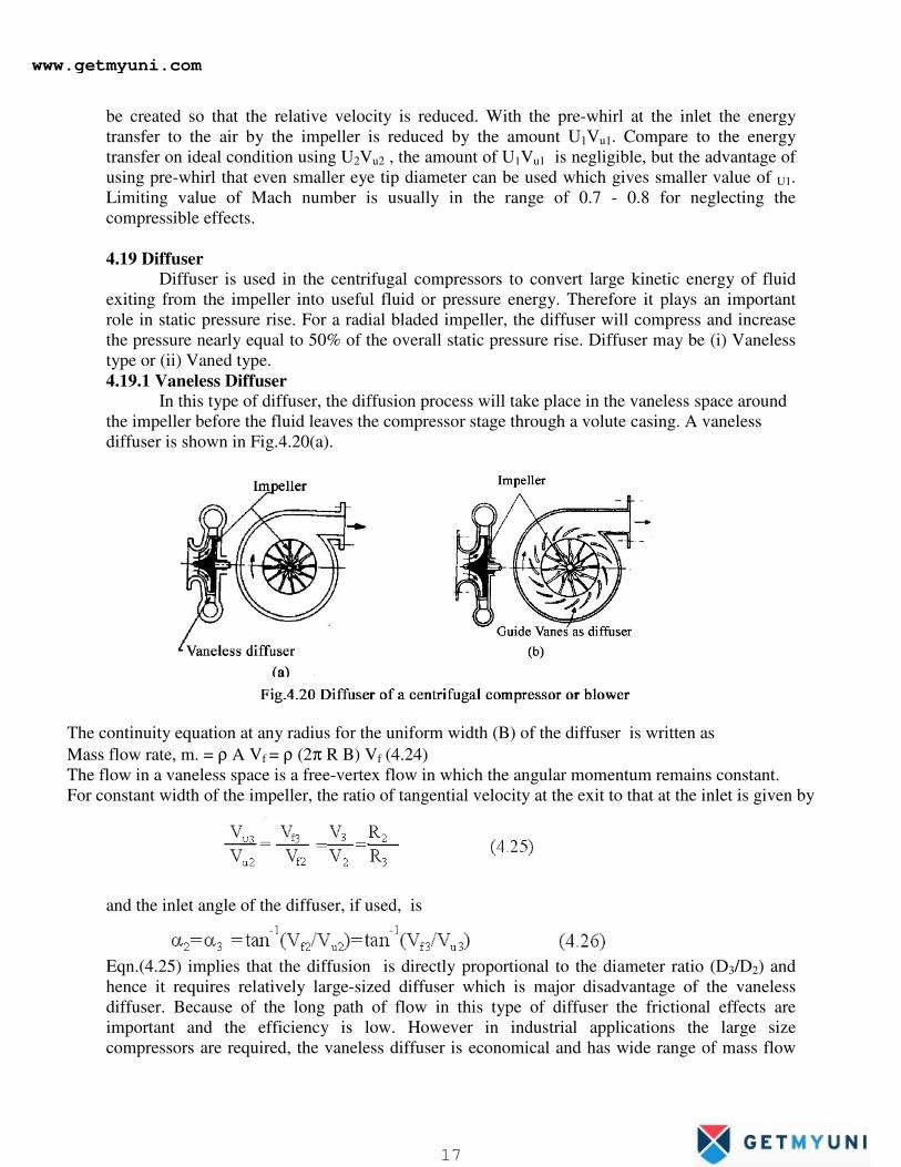
4.19.1 Vaneless Diffuser
In this type of diffuser, the diffusion process will take place in the vaneless space around
the impeller before the fluid leaves the compressor stage through a volute casing. A vaneless
diffuser is shown in Fig.4.20(a).
and the inlet angle of the diffuser, if used, is
Eqn.(4.25) implies that the diffusion is directly proportional to the diameter ratio (D3/D2) and
hence it requires relatively large-sized diffuser which is major disadvantage of the vaneless
diffuser. Because of the long path of flow in this type of diffuser the frictional effects are
important and the efficiency is low. However in industrial applications the large size
compressors are required, the vaneless diffuser is economical and has wide range of mass flow
www.getmyuni.com
17
rates. The most advantage of the vaneless diffuser is that it will not suffer from stalling and
shock waves.
4.19.2 Vaned Diffuser
In vaned diffuser as shown in Fig.4.20(b)the vanes either straight type or aerofoil type are
used to diffuse the large kinetic energy with shorter length and high efficiency compared to the
vaneless diffuser. In this case the length of flow travel and the diameter are reduced. It consists
of a ring of diffuser vanes around the impeller and the fluid enters the diffuser through the short
vaneless space. The diffuser blades are such that the area towards the exit is keep on increasing
so that more diffusion can be achieved with less travel length. The rate of diffusion mainly
controlled by the diffuser blade angle which is usually kept less than 120 to avoid the boundary
layer separation. More number of vanes also can not employed since they increase the frictional
losses. To avoid possibilities of rotating stall, boundary layer separation and frictional losses, less
number of diffuser vanes are used than that of the impeller. In some cases the number of
diffuser blades is kept one-third of the number of the impeller blades.
The diffuser efficiency is defined as
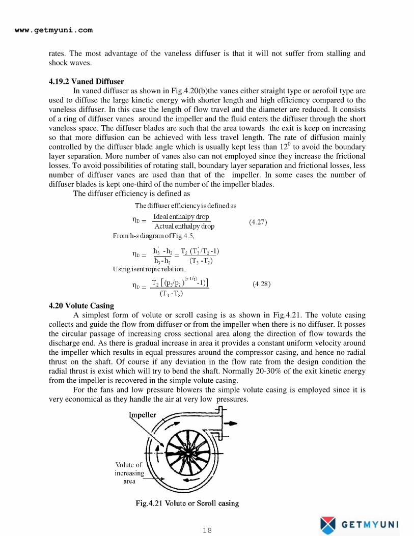
4.20 Volute Casing
A simplest form of volute or scroll casing is as shown in Fig.4.21. The volute casing
collects and guide the flow from diffuser or from the impeller when there is no diffuser. It posses
the circular passage of increasing cross sectional area along the direction of flow towards the
discharge end. As there is gradual increase in area it provides a constant uniform velocity around
the impeller which results in equal pressures around the compressor casing, and hence no radial
thrust on the shaft. Of course if any deviation in the flow rate from the design condition the
radial thrust is exist which will try to bend the shaft. Normally 20-30% of the exit kinetic energy
from the impeller is recovered in the simple volute casing.
For the fans and low pressure blowers the simple volute casing is employed since it is
very economical as they handle the air at very low pressures.
www.getmyuni.com
18
www.getmyuni.com
19
www.getmyuni.com
20
www.getmyuni.com
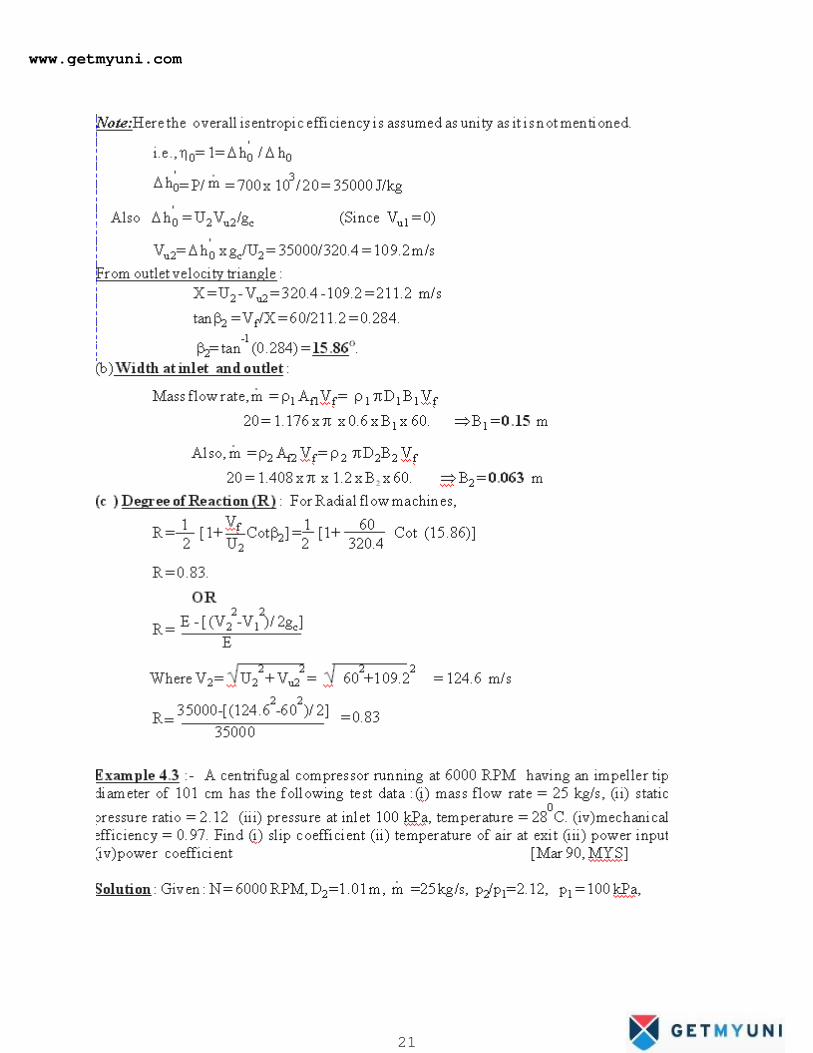
21
www.getmyuni.com
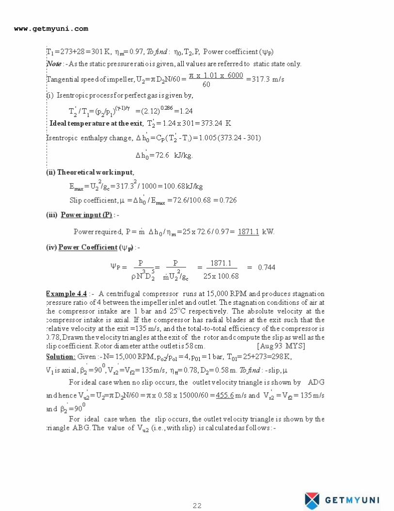
22
www.getmyuni.com
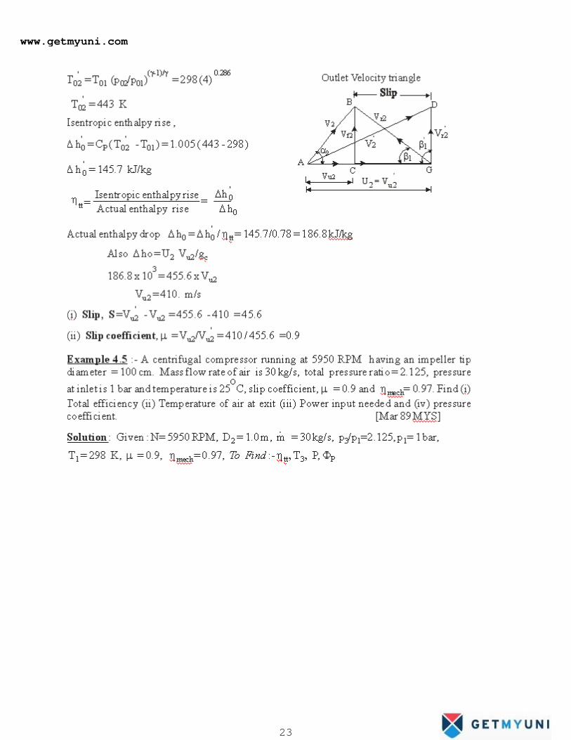
23
www.getmyuni.com
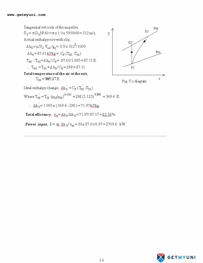
24
www.getmyuni.com
25
www.getmyuni.com
26
www.getmyuni.com
27
www.getmyuni.com
28