CENTRIFUGAL COMPRESSORS Pushing the Envelope · PDF fileCENTRIFUGAL COMPRESSORS ... Pushing...
5
© 2013 ANSYS, INC. ANSYS ADVANTAGE Volume VII | Issue 3 | 2013 16 CENTRIFUGAL COMPRESSORS Dresser-Rand designs compressor stages to operate at higher flow coefficients and higher machine or inlet-relative Mach numbers. Pushing the Envelope CFD simulation contributes to increasing the operating envelope of a centrifugal compressor stage. By James M. Sorokes, Principal Engineer; Jorge E. Pacheco, Manager, Aero/Thermo Design Engineering; and Kalyan C. Malnedi, Manager, Solid Mechanics Group, Dresser-Rand Company, Olean, U.S.A. C entrifugal compressors, also called radial compressors, play a critical role in many process industries, including oil and gas, petro- chemical, and gas transmission. These machines are used to compress a gas or a gas–liquid mixture into a smaller volume while increasing its pressure and temperature. COMPRESSOR DESIGN CHALLENGES Process industries are looking for smaller- footprint compressors for space-sensi- tive applications, such as offshore, subsea and compact plant designs. Dresser-Rand reduces compressor footprints by design- ing stages to operate at higher flow coefficients and higher machine or inlet- relative Mach numbers. The company is among the largest global suppliers of rotating equipment solutions for long-life, critical applications. In recent years, the industry has placed greater emphasis on achieving a wide operating range so that, for exam- ple, compressors can handle a wider range of flow rates at different stages of a well’s lifecycle. Engineering simulation is an important tool in addressing these market challenges. Dresser-Rand has been using ANSYS CFX software since the 1990s to develop many new compressor designs for process industries and other applications. Two factors limit the overall operating range of a compressor: surge or stall mar- gin, and overload capacity. Surge or stall margin limits the compressor’s ability to operate at flow rates lower than design, while overload capacity limits the ability to operate at higher rates. Rotating stall arises when small regions of low momen- tum or low pressure (referred to as stall cells) form in the flow passages and begin to rotate around the circumference of the compressor. These flow and/or pressure
Transcript of CENTRIFUGAL COMPRESSORS Pushing the Envelope · PDF fileCENTRIFUGAL COMPRESSORS ... Pushing...

© 2013 ANSYS, INC. ANSYS ADVANTAGE Volume VII | Issue 3 | 2013 16
CENTRIFUGAL COMPRESSORS
Dresser-Rand designs compressor stages to operate at higher flow coefficients and higher machine or inlet-relative Mach numbers.
Pushing the Envelope
CFD simulation contributes to increasing the operating envelope of a centrifugal compressor stage.By James M. Sorokes, Principal Engineer; Jorge E. Pacheco, Manager, Aero/Thermo Design Engineering; and Kalyan C. Malnedi, Manager, Solid Mechanics Group, Dresser-Rand Company, Olean, U.S.A.
C�entrifugal compressors, also called radial compressors, play a critical role in many process
industries, including oil and gas, petro-chemical, and gas transmission. These machines are used to compress a gas or a gas–liquid mixture into a smaller volume while increasing its pressure and temperature.
COMPRESSOR DESIGN CHALLENGESProcess industries are looking for smaller-footprint compressors for space-sensi-tive applications, such as offshore, subsea and compact plant designs. Dresser-Rand reduces compressor footprints by design-ing stages to operate at higher flow coefficients and higher machine or inlet-relative Mach numbers. The company is among the largest global suppliers of rotating equipment solutions for long-life, critical applications.
In recent years, the industry has placed greater emphasis on achieving a wide operating range so that, for exam-ple, compressors can handle a wider range of flow rates at different stages of a well’s lifecycle. Engineering simulation is an important tool in addressing these market challenges. Dresser-Rand has been using ANSYS CFX software since the 1990s to develop many new compressor designs for process industries and other applications.
Two factors limit the overall operating range of a compressor: surge or stall mar-gin, and overload capacity. Surge or stall margin limits the compressor’s ability to operate at flow rates lower than design, while overload capacity limits the ability to operate at higher rates. Rotating stall arises when small regions of low momen-tum or low pressure (referred to as stall cells) form in the flow passages and begin to rotate around the circumference of the compressor. These flow and/or pressure
© 2013 ANSYS, INC. ANSYS ADVANTAGE Volume VII | Issue 3 | 2013 17
� Centrifugal compressors operate by adding velocity pressure or kinetic energy to the fluid stream and then converting that kinetic energy into potential energy in the form of static pressure. Kinetic energy is added by rotating impellers, while the conversion of velocity pressure to static pressure occurs in downstream stationary components such as diffusers, return channels and volutes.
disturbances cause unbalanced forces on the compressor rotor, leading to unwanted vibration issues and reduced compres-sor performance. Surge occurs when the compressor is no longer able to overcome the pressure in the downstream pip-ing and pressure vessels, and the flow is forced backward through the compressor.
For most centrifugal stages that oper-ate at high inlet-relative Mach numbers, low-momentum regions can form along the shroud side of parallel-wall vaneless diffusers. Typically the size of this region increases as flow is reduced until diffuser stall results. In developing a new high-head stage for a high–Mach number com-pressor, the Dresser-Rand team observed an interesting phenomenon both in com-putational fluid dynamics (CFD) simula-tion and test results: A sudden migration
of the low-momentum region from the shroud side to the hub side of the diffuser occurred as the flow rate reduced, just prior to stall [1]. The impeller used in the study is operated over a machine Mach number range of 0.85 to 1.20. The initial design had a vaneless diffuser that was pinched at the shroud and then followed by a parallel wall section. In analyzing test results, engineers established that the shift of the high-momentum region occurred much earlier for this high-head stage than for lower-head stages. As a result, the surge margin was significantly lower than low-head stages, an unac-ceptable drop in operating range. Since the stationary components were stalling before the impeller due to low momentum shift, the team decided to use CFD to opti-mize the diffuser and return channel.
USING CFD TO OPTIMIZE THE DESIGNDresser-Rand engineers conducted all analyses using ANSYS CFX software for a sector model that included the upstream inlet guide vane, impeller, diffuser, return bend, return channel and exit section. In this case, the grid was composed of more than 5 million total elements using a tet-rahedral mesh with wedge elements for the boundary layers. Engineers modeled the interfaces between stationary and rotating components using a stage inter-face that performs a circumferential aver-aging of the fluxes through bands on the interface. The k-epsilon turbulence model and a high-resolution discretization scheme were used.
The team evaluated several combi-nations of pinch, shroud-tapered and

© 2013 ANSYS, INC. ANSYS ADVANTAGE Volume VII | Issue 3 | 2013 18
CENTRIFUGAL COMPRESSORS
hub-tapered diffusers. Engineers iterated to a diffuser design that is pinched and tapered on both hub and shroud sides to significantly reduce low-momentum regions that were forming on either side of the diffuser exit at low flow. They reduced the return channel width and redesigned the return channel vanes to match the new flow incidence. CFD results showed that the new design significantly reduced the size of the low-momentum region in the diffuser and return channel. It also considerably delayed the shift of the low-momentum region from the shroud side to the hub side, delaying the onset of stall.
Comparison between the original and optimized designs shows a substantial reduction in the absolute velocity flow angle
� Velocity profile at 90 percent flow for the optimized stationary component design shows a much smaller low-momentum region.
� Absolute velocity flow angle at the diffuser exit for the original design shows high tangential-flow angles, indicative of low-momentum flow that often leads to formation of stall cells.
� Absolute velocity flow angle at the diffuser exit for the optimized design shows greatly reduced high tangential-flow angles.
Inlet
Inlet guide vane
Impeller
Hub
� Velocity profile at 90 percent flow for the original stationary component design shows a large low-momentum region at the hub side in the vaneless diffuser and return bend.
relative to the radial line at the diffuser exit plane. Highly tan-gential flow angles greater than 75 degrees generally are indic-ative of very low momentum, which leads to formation of stall cells in stationary components. The pressure recovery plots for both original and optimized geometries show that the optimized geometry has lower pressure recovery on the overload side but better performance on the surge side. The lower recovery at over-load for the optimized geometry is most likely due to the nar-row stationary component passages, which results in higher gas velocities and lower pressure recovery. However, this geometry also contributes to improving the flow in the stationary compo-nents, resulting in better pressure recovery at lower flow. The
Return bend
Vaneless diffuser
ShroudReturn channel vanes

© 2013 ANSYS, INC. ANSYS ADVANTAGE Volume VII | Issue 3 | 2013 19
Structural AnalysisDresser-Rand structural engineers optimize the impeller design to keep the static stresses both below those seen in similar families of impellers and below allowable mate-rial yield strengths. The lower the stresses, the faster the impeller can be run. During the design process, engineers also analyze the design to see if there are any possible res-onance issues caused by upstream or downstream station-ary components.
Most of the time, structural damages to the impellers are due to mechanical fatigue. Dresser-Rand follows the in-house dynamic audit process [3] to evaluate the fatigue life of the impellers. The dynamic audit process involves a series of successive analysis runs, starting with a modal analysis and plotting of a SAFE diagram [4] for identifying interfer-ences. This is followed by harmonic response analyses to compute dynamic stress levels in an impeller at identified SAFE interferences. A minimum factor of safety is then com-puted for all locations in the impeller based on the static and dynamic stresses, material properties and the construction method used for that impeller. The structural team has auto-mated much of the structural design process by writing APDL macros and FORTRAN programs, which have reduced sim-ulation time from more than a week to one to two days per design iteration.
� Typical steady-state plot of impeller
� Industrial centrifugal compressor COURTESY DRESSER-RAND.
Tests validated CFD simulation prediction of about 10 percent improvement in the surge margin of the new design.
CFD results predicted an improvement in surge margin of approx-imately 15 percent.
Tests validated CFD simulation prediction of an improve-ment of about 10 percent in the surge margin of the new design. Flow angle measurements at the diffuser inlet, diffuser exit and return channel inlet confirmed the CFD prediction of a delay in the low-momentum shift. Further, the redesign was successful in maintaining the same head and efficiency levels as the pre-vious design had. About 1.5 percent of overload margin was lost due to the reduced passage areas in the stationary compo-nents. However, this was deemed acceptable, as the stage is not expected to be operated at high flow levels close to choke.
Impellers are subjected to inlet and exit flow variations through the stage, and therefore they must be designed to with-stand the alternating pressure loads due to these variations in addition to withstanding steady loads. The structural team used ANSYS Mechanical software and in-house tools to ensure that the new design meets the static and dynamic stress requirements.
Dresser-Rand’s use of CFD simulation to optimize the sta-tionary components of a new centrifugal compressor design
© 2013 ANSYS, INC. ANSYS ADVANTAGE Volume VII | Issue 3 | 2013 20
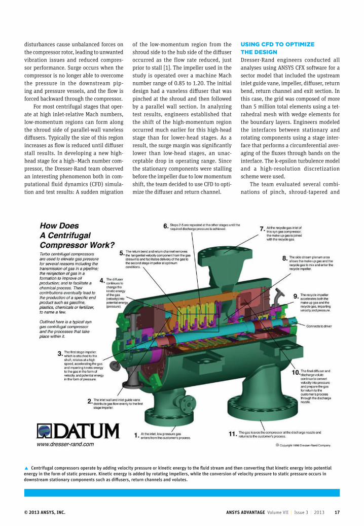
� The optimized design shows better pressure recovery on the surge (left) side of the pressure recovery curve.
� CFD results and physical tests provide similar estimates of compressor efficiency.
� Testing shows that optimized design improves the operating range.
Performance Parameter Original Design Optimized Design
Normalized polytropic efficiency at design flow 1.000 1.001
Normalized polytropic head coefficient at design flow 1.000 1.003
Surge margin 6.1 16.0
Overload margin 13.4 12.1
accomplished several goals: This new design delayed the transfer of the low-momentum zone from the shroud side of the diffuser to the hub side, and it shows how proper sizing of stationary compo-nents in the early stages of the design process can increase the compressor’s operating range. The end result is that Dresser-Rand delivered a highly efficient compressor with a wide operating range in a small footprint [2].
References[1] Sorokes, J. M.; Pacheco, J. E.; Vezier, C.; Fakhri, S.
"An Analytical and Experimental Assessment of
a Diffuser Flow Phenomenon as a Precursor to
Stall". Proceedings of ASME Turbo Expo 2012, 2012,
Volume 8: Turbomachinery, Parts A, B and C.
[2] Fakhri, S.; Sorokes, J. M.; Vezier, C.; Pacheco,
J. E. "Stationary Component Optimization and
the Resultant Improvement in the Performance
Characteristics of a Radial Compressor Stage".
Proceedings of ASME Turbo Expo 2013, 2013.
[3] Schiffer, D. M.; Syed, A. An "Impeller Dynamic
Risk Assessment Toolkit". Proceedings of the 35th
Turbomachinery Symposium, 2006, pp. 49–54.
[4] Singh, M. P.; Vargo, J. J.; Schiffer, D. M.;
Dello, J. D. "SAFE Diagram — A Design and
Reliability Tool for Turbine Blading". Proceedings of
the Seventeenth Turbomachinery Symposium, 1988,
pp. 93–101.
Dresser-Rand delivered a highly efficient compressor with a wide operating range in a small footprint.
CENTRIFUGAL COMPRESSORS