
Centralized Lubrication for Wheel+Rail - GRUPO VEI · Fittings and accessories ... This catalog...
36
1-8092-US Centralized Lubrication for Wheel+Rail Standard systems and special solutions based on decades of experience Wheel flange lubrication systems for: • High-speed trains • Local trains • Shunting engines • Subway and elevated trains • Streetcars
-
Upload
nguyenthien -
Category
Documents
-
view
219 -
download
0
Transcript of Centralized Lubrication for Wheel+Rail - GRUPO VEI · Fittings and accessories ... This catalog...
1-8092-US
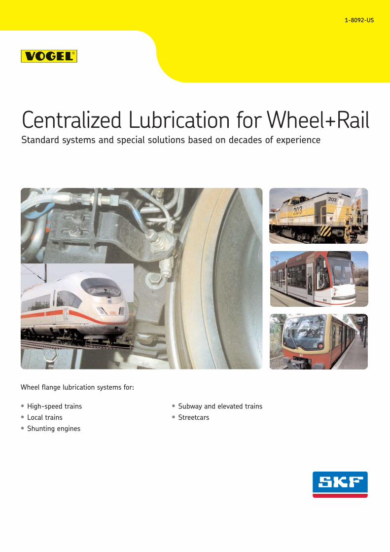
Centralized Lubrication for Wheel+RailStandard systems and special solutions based on decades of experience
Wheel flange lubrication systems for:
• High-speed trains• Local trains• Shunting engines
• Subway and elevated trains• Streetcars
Centralized Lubrication for Wheel+Rail
2 1-8092-US
Page
Indroduction . . . . . . . . . . . . . . . . . . . . . . . . . . . . . . . . . . . . . . . . . . . . . . . . . . . . . . . . . . . . . . . . . . . . . . 4 Comparison of systems . . . . . . . . . . . . . . . . . . . . . . . . . . . . . . . . . . . . . . . . . . . . . . . . . . . . . . . . . . . . . 4Lubricants . . . . . . . . . . . . . . . . . . . . . . . . . . . . . . . . . . . . . . . . . . . . . . . . . . . . . . . . . . . . . . . . . . . . . . . 5
System SP8 . . . . . . . . . . . . . . . . . . . . . . . . . . . . . . . . . . . . . . . . . . . . . . . . . . . . . . . . . . . . . . . . . . . . . . 6
SP10, SP8-4, SP8-2 Spray nozzle . . . . . . . . . . . . . . . . . . . . . . . . . . . . . . . . . . . . . . . . . . . . . . . . 7PF-100-21 Piston pump with reservoir . . . . . . . . . . . . . . . . . . . . . . . . . . . . . . . . . . . . . . . . . . . . 8112-508-042 Piston pump with reservoir . . . . . . . . . . . . . . . . . . . . . . . . . . . . . . . . . . . . . . . . . . 9SF10 Grease control valve . . . . . . . . . . . . . . . . . . . . . . . . . . . . . . . . . . . . . . . . . . . . . . . . . . . . . . 10STG12-2, STG13 Valve unit . . . . . . . . . . . . . . . . . . . . . . . . . . . . . . . . . . . . . . . . . . . . . . . . . . . . . 11
System SP9 . . . . . . . . . . . . . . . . . . . . . . . . . . . . . . . . . . . . . . . . . . . . . . . . . . . . . . . . . . . . . . . . . . . . . 12
SP9-2, SP9-2-S7 Spray nozzle . . . . . . . . . . . . . . . . . . . . . . . . . . . . . . . . . . . . . . . . . . . . . . . . . 13BF4.5 Grease reservoir . . . . . . . . . . . . . . . . . . . . . . . . . . . . . . . . . . . . . . . . . . . . . . . . . . . . . . . . . 14BF6-S3 Grease reservoir . . . . . . . . . . . . . . . . . . . . . . . . . . . . . . . . . . . . . . . . . . . . . . . . . . . . . . . 15
System Tram with its own supply of compressed air . . . . . . . . . . . . . . . . . . . . . . . . . . . . . . . . . . . 16
169-000-208, 169-000-209 Spray nozzle . . . . . . . . . . . . . . . . . . . . . . . . . . . . . . . . . . . . . . . . 17PEF-98 Piston pump with reservoir . . . . . . . . . . . . . . . . . . . . . . . . . . . . . . . . . . . . . . . . . . . . . . 18PEU-98 Piston pump with reservoi . . . . . . . . . . . . . . . . . . . . . . . . . . . . . . . . . . . . . . . . . . . . . . . 19169-000-205 Mixing block . . . . . . . . . . . . . . . . . . . . . . . . . . . . . . . . . . . . . . . . . . . . . . . . . . . . . . 20VKSO Piston distributor . . . . . . . . . . . . . . . . . . . . . . . . . . . . . . . . . . . . . . . . . . . . . . . . . . . . . . . . . 21
CS200 Curve sensor control unit . . . . . . . . . . . . . . . . . . . . . . . . . . . . . . . . . . . . . . . . . . . . . . . . . . 22
CS200-S1+902 Curve sensor control unit . . . . . . . . . . . . . . . . . . . . . . . . . . . . . . . . . . . . . . . . . . 23
IG665, IG666, IG667 Control units . . . . . . . . . . . . . . . . . . . . . . . . . . . . . . . . . . . . . . . . . . . . . . 24/25
3/2-way valve, valve manifolds . . . . . . . . . . . . . . . . . . . . . . . . . . . . . . . . . . . . . . . . . . . . . . . . . . 26/27
169-000-084 Topping-up pump . . . . . . . . . . . . . . . . . . . . . . . . . . . . . . . . . . . . . . . . . . . . . . . . . . 28
Fittings and accessories . . . . . . . . . . . . . . . . . . . . . . . . . . . . . . . . . . . . . . . . . . . . . . . . . . . . . . . . 29/32
Checklist – wheel-flange lubrication . . . . . . . . . . . . . . . . . . . . . . . . . . . . . . . . . . . . . . . . . . . . . 33/34
Table of Contents
Centralized Lubrication for Wheel+Rail
3 1-8092-US
VOGEL Centralized Lubrication for Wheel+Rail Cuts Life Cycle Costs (LCC), Friction and Wear!
�� Track resistance drops by 30 to 35%, more energy available. No effect on traction or braking.
�� 12 to 15% less energy consumed Lower energy costs make themselves felt at once.
�� Wear cut by 30 to 80%.Longer intervals between reshaping or replacement of wheel sets ans rails, maintenance time is minimized.
�� Greater safety Less danger of derailment because it is harder for wheel flanges to climb out of the tracks.
VOGEL systems are in use around the world. Our products provide solutions to problems in any operating conditions:Pin-point accuracy with no compromises!
This catalog will show you how VOGEL wheel flange lubrication sys-tems work so that you can plan, install and properly maintain corre-sponding systems.
A wheel flange lubrication system is installed either by the manufac-turer at the factory or at a later date by trained shop staff, our skilledpersonnel or by you yourself if you have the requisite knowledge. Weprovide supportive technical training and assembly training coursesfor this purpose.
VOGEL sells wheel flange lubrication systems for nearly every kind ofrail vehicle such as locomotives, multiple-train units, subways, elevat-ed trains and streetcars as well as other rail-bound vehicles. Systemplans and parts lists are available for a large number of applications.
VOGEL's field staff will be pleased to advise you. Make use of ourexperience!
Importance of wheel flange lubricationWhen rail vehicles are in motion the frictionbetween the wheel and rail leads to highwear and tear on the wheel flanges and railfaces, undesirable screeching (above all incurves) and considerable energy losses during acceleration. Moreover, the danger ofderailment also grows when wheel flangesare left unlubricated.
Selective, precision application of lubricant tothe flange faces of the locomotive or motorcar wheels lubricates not only these wheelsand rail face but also all the following wheels,e.g. of passenger or freight cars.
The lubricant sprayed on the first wheelflange in the direction of travel is transferredto the rail face, thus lubricating the followingwheel flanges.
Optimally configured wheel flange lubricationsystems supply as many as 250 axles. A largenumber of motor cars with wheel flangelubrication assures requisite lubrication of therail network, the basis on which wheel flangelubrication systems achieve the desiredeffect.
The service life of wheelsets and tracks canbe considerably extended. Travel of up to500,000 km before the wheelsets have to berecontoured is no longer a rarity. A wheelflange lubrication system often pays for itselfin just one year's time. And that doesn'tinclude the savings resulting from longer raillife, above all in curves.
Thanks to their high reliability and importantdevelopments in control and monitoringtechniques, VOGEL wheel flange lubricationsystems can be adapted to any type of railvehicle.
Types of wheel flange lubricationVOGEL has been producing and selling vari-ous types of wheel flange lubrication systemsfor rail vehicles for many years now.
The systems assure high metering accuracy,regardless of fluctuations in air pressure ortemperature. That is one of their mainadvantages and the reason for their world-wide spread.
A large number of possible combinations andperfected control technology make it possibleto choose the optimal wheel flange lubrica-tion system for the respective operating con-ditions.
Control and monitoringIf until recently the control of wheel flangelubrication systems was generally seen to bythe vehicle's control system, e.g. the locomo-tive, increasing use is now being made ofspecial control and monitoring equipmentdesigned exclusively for wheel flange lubrica-tion. This is especially the case when theusual functional range of the vehicle's controlsystem isn't up to the special needs of wheelflange lubrication, or when a clear separationof responsibility is desired and the usershould be able to make necessary changes inlube operations (e.g. shorter lube intervals,switchover from time- to distance-dependentcontrol) without having to interfere with thevehicle software.
Centralized Lubrication for Wheel+Rail
4 1-8092-US
Introduction
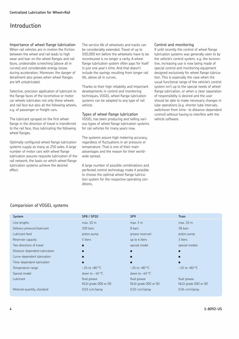
System SP8 / SP10 SP9 Tram
Line lengths max. 10 m max. 5 m max. 10 m
Delivery pressure/lubricant 100 bars 8 bars 38 bars
Lubricant feed piston pump grease reservoir piston pump
Reservoir capacity 5 liters up to 6 liters 3 liters
Two directions of travel � special model special models
Distance-dependent lubrication � � �
Curve-dependent lubrication � � �
Time-dependent lubrication � � �
Temperature range –25 to +80 °C –25 to +80 °C –25 to +80 °C
Special model down to –40 °C down to –40 °C
Lubricant fluid grease fluid grease fluid greaseNLGI grade 000 or 00 NLGI grade 000 or 00 NLGI grade 000 or 00
Metered quantity, standard 0.03 ccm/spray 0.03 ccm/spray 0.04 ccm/spray
Comparision of VOGEL systems
The quality of the lubricants has a decisiveinfluence on the efficacy of the lubricationapplied to the wheel-rail interface. In theend, it determines the friction, wear andnoise. In the last few years attempts havebeen made to achieve optimal surfacesmoothness and minimal wear with the helpof increasingly higher percentages of solids.Regardless of the fact that a certain amountof wheel flange wear is necessary for properfunctioning of the wheel-rail interface, sinceundesirable growth in the diameter of thewheel flange likewise increases the danger ofderailment, solid particles in the lubricant areonly good as long as they do not lead toclogged systems, thereby jamming the wheelflange lubrication installation.
That is why the makers of lubricants andwheel flange lubrication systems as well asthe operators of rail vehicles have all worked
together to develop a number of special bio-degradable lubricants for wheel flange lubri-cation systems and separating agents forrailhead lubrication. The greases are made of substances that are broken down into theirbasic ingredients by ubiquitous microorgan-isms as quickly and completely as possible.They have to be usable not only for newwheel flange lubrication systems but also forthe thousands of systems installed years ago.
In general, NLGI grade 000 and 00 fluidgrease is used in the systems made byVOGEL. The grease can contain as much as30% solids. The systems can also be operat-ed with all the wheel flange lubricatinggrease approved by the Deutsche Bahn AG(German Railways).
The lubricants recommended for certaintypes of systems by the manufacturers canbe found in corresponding lists of approvedproducts. After extensive testing theDeutsche Bahn AG, for instance, also assignsso-called “material numbers” to suitablelubricants and approves them for use in itsvehicles.
The lubricants approved for VOGEL's wheelflange lubrication systems can be found in an updated list on the Internet atwww.vogelag.com.
Centralized Lubrication for Wheel+Rail
5 1-8092-US
Lubricants
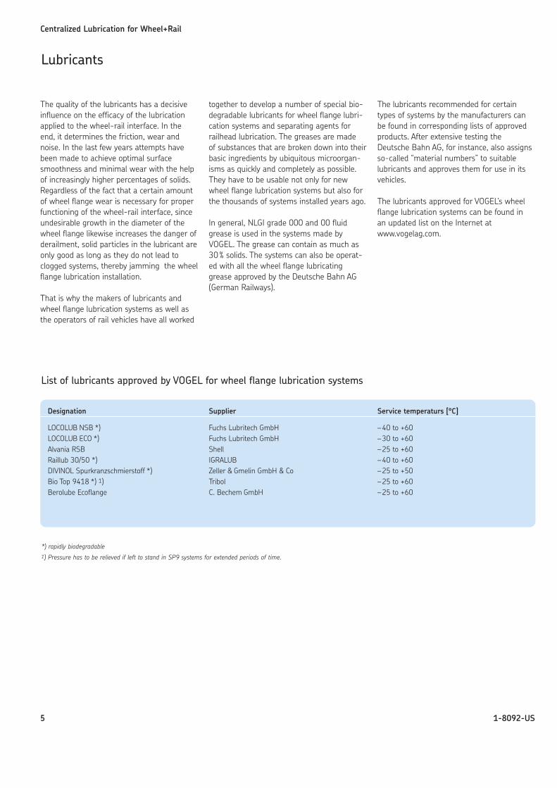
Designation Supplier Service temperaturs [°C]
LOCOLUB NSB *) Fuchs Lubritech GmbH –40 to +60LOCOLUB ECO *) Fuchs Lubritech GmbH –30 to +60Alvania RSB Shell –25 to +60Raillub 30/50 *) IGRALUB –40 to +60DIVINOL Spurkranzschmierstoff *) Zeller & Gmelin GmbH & Co –25 to +50Bio Top 9418 *) 1) Tribol –25 to +60Berolube Ecoflange C. Bechem GmbH –25 to +60
List of lubricants approved by VOGEL for wheel flange lubrication systems
*) rapidly biodegradable1) Pressure has to be relieved if left to stand in SP9 systems for extended periods of time.
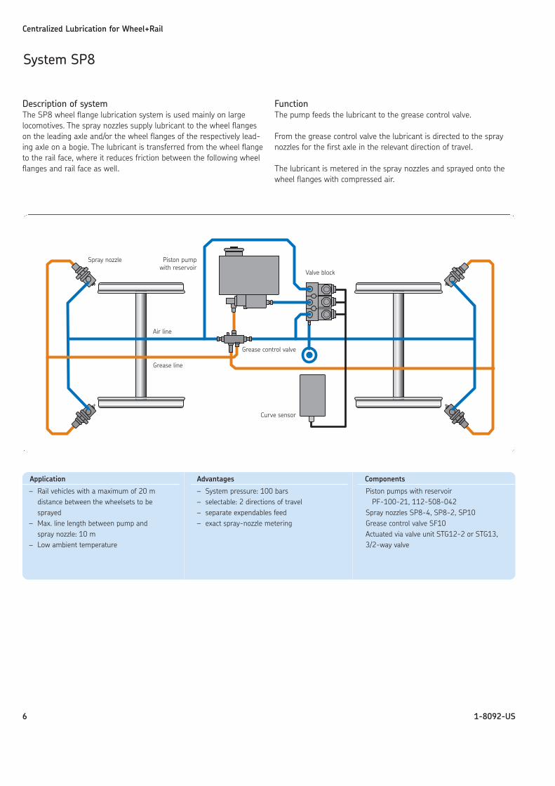
Description of systemThe SP8 wheel flange lubrication system is used mainly on largelocomotives. The spray nozzles supply lubricant to the wheel flangeson the leading axle and/or the wheel flanges of the respectively lead-ing axle on a bogie. The lubricant is transferred from the wheel flangeto the rail face, where it reduces friction between the following wheelflanges and rail face as well.
FunctionThe pump feeds the lubricant to the grease control valve.
From the grease control valve the lubricant is directed to the spraynozzles for the first axle in the relevant direction of travel.
The lubricant is metered in the spray nozzles and sprayed onto thewheel flanges with compressed air.
Centralized Lubrication for Wheel+Rail
6 1-8092-US
System SP8
Application
– Rail vehicles with a maximum of 20 m distance between the wheelsets to besprayed
– Max. line length between pump and spray nozzle: 10 m
– Low ambient temperature
Advantages
– System pressure: 100 bars – selectable: 2 directions of travel– separate expendables feed– exact spray-nozzle metering
Components
Piston pumps with reservoirPF-100-21, 112-508-042
Spray nozzles SP8-4, SP8-2, SP10Grease control valve SF10Actuated via valve unit STG12-2 or STG13,3/2-way valve
Air line
Grease line
Valve block
Grease control valve
Curve sensor
Piston pump with reservoir
Spray nozzle
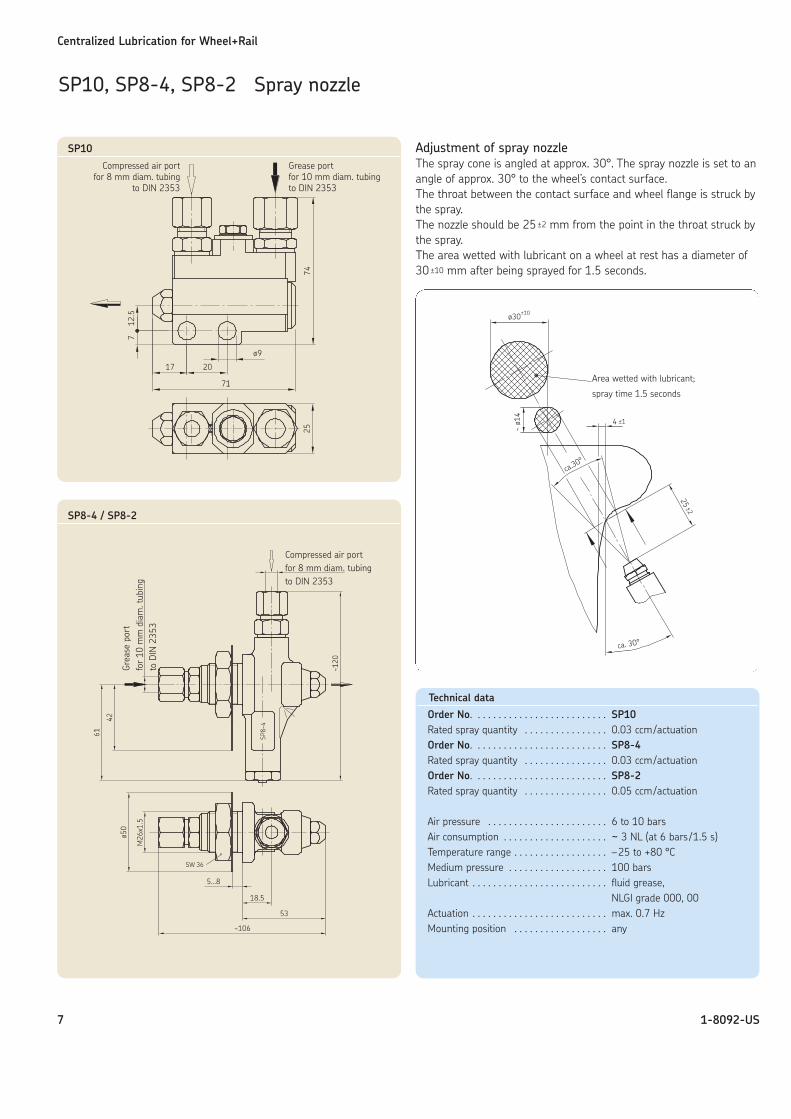
Adjustment of spray nozzleThe spray cone is angled at approx. 30°. The spray nozzle is set to anangle of approx. 30° to the wheel’s contact surface.The throat between the contact surface and wheel flange is struck bythe spray.The nozzle should be 25 ±2 mm from the point in the throat struck bythe spray.The area wetted with lubricant on a wheel at rest has a diameter of30 ±10 mm after being sprayed for 1.5 seconds.
Centralized Lubrication for Wheel+Rail
7 1-8092-US
SP10, SP8-4, SP8-2 Spray nozzle
SP10
SP8-4 / SP8-2
Technical data
Order No. . . . . . . . . . . . . . . . . . . . . . . . . . SP10Rated spray quantity . . . . . . . . . . . . . . . . 0.03 ccm/actuationOrder No. . . . . . . . . . . . . . . . . . . . . . . . . . SP8-4Rated spray quantity . . . . . . . . . . . . . . . . 0.03 ccm/actuationOrder No. . . . . . . . . . . . . . . . . . . . . . . . . . SP8-2Rated spray quantity . . . . . . . . . . . . . . . . 0.05 ccm/actuation
Air pressure . . . . . . . . . . . . . . . . . . . . . . . 6 to 10 barsAir consumption . . . . . . . . . . . . . . . . . . . . ~ 3 NL (at 6 bars /1.5 s)Temperature range . . . . . . . . . . . . . . . . . . –25 to +80 °CMedium pressure . . . . . . . . . . . . . . . . . . . 100 barsLubricant . . . . . . . . . . . . . . . . . . . . . . . . . . fluid grease,
NLGI grade 000, 00Actuation . . . . . . . . . . . . . . . . . . . . . . . . . . max. 0.7 HzMounting position . . . . . . . . . . . . . . . . . . any
Area wetted with lubricant;
spray time 1.5 seconds
Compressed air portfor 8 mm diam. tubing
to DIN 2353
Grease portfor 10 mm diam. tubingto DIN 2353
Compressed air portfor 8 mm diam. tubing to DIN 2353
Grea
se p
ort
for
10 m
m d
iam
. tub
ing
to D
IN 2
353
Centralized Lubrication for Wheel+Rail
8 1-8092-US
Technical data
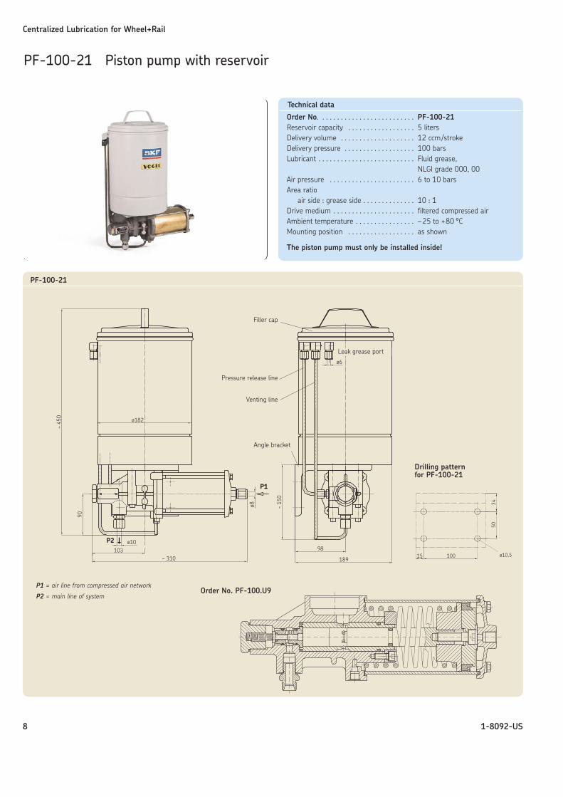
Order No. . . . . . . . . . . . . . . . . . . . . . . . . . PF-100-21Reservoir capacity . . . . . . . . . . . . . . . . . . 5 litersDelivery volume . . . . . . . . . . . . . . . . . . . . 12 ccm/strokeDelivery pressure . . . . . . . . . . . . . . . . . . . 100 barsLubricant . . . . . . . . . . . . . . . . . . . . . . . . . . Fluid grease,
NLGI grade 000, 00Air pressure . . . . . . . . . . . . . . . . . . . . . . . 6 to 10 barsArea ratio
air side : grease side . . . . . . . . . . . . . . 10 : 1Drive medium . . . . . . . . . . . . . . . . . . . . . . filtered compressed airAmbient temperature . . . . . . . . . . . . . . . . –25 to +80 °CMounting position . . . . . . . . . . . . . . . . . . as shown
The piston pump must only be installed inside!
PF-100-21 Piston pump with reservoir
Filler cap
Pressure release line
Venting line
Angle bracket
Leak grease port
P1
P2
PF-100-21
Drilling pattern for PF-100-21
Order No. PF-100.U9P1 = air line from compressed air network
P2 = main line of system
Centralized Lubrication for Wheel+Rail
9 1-8092-US
Technical data
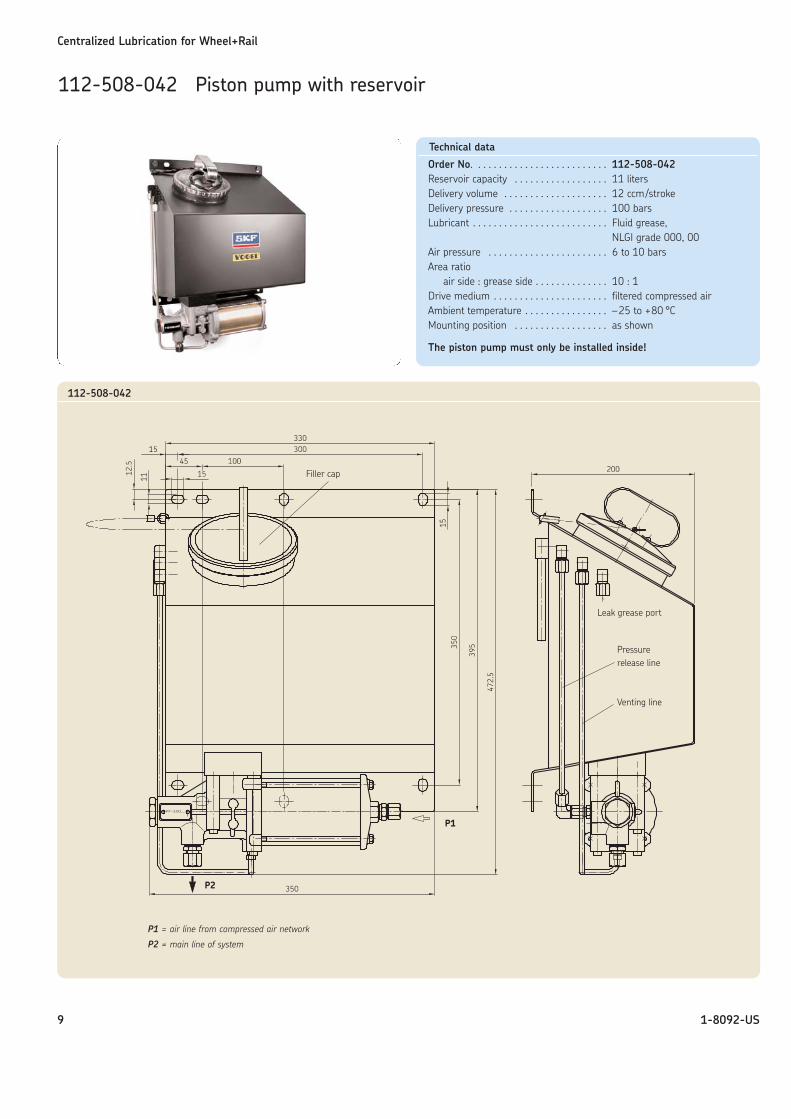
Order No. . . . . . . . . . . . . . . . . . . . . . . . . . 112-508-042Reservoir capacity . . . . . . . . . . . . . . . . . . 11 litersDelivery volume . . . . . . . . . . . . . . . . . . . . 12 ccm/strokeDelivery pressure . . . . . . . . . . . . . . . . . . . 100 barsLubricant . . . . . . . . . . . . . . . . . . . . . . . . . . Fluid grease,
NLGI grade 000, 00Air pressure . . . . . . . . . . . . . . . . . . . . . . . 6 to 10 barsArea ratio
air side : grease side . . . . . . . . . . . . . . 10 : 1Drive medium . . . . . . . . . . . . . . . . . . . . . . filtered compressed airAmbient temperature . . . . . . . . . . . . . . . . –25 to +80 °CMounting position . . . . . . . . . . . . . . . . . . as shown
The piston pump must only be installed inside!
112-508-042 Piston pump with reservoir
112-508-042
Leak grease port
P1
P2
P1 = air line from compressed air network
P2 = main line of system
Filler cap
Pressure release line
Venting line
Centralized Lubrication for Wheel+Rail
10 1-8092-US
Technical data
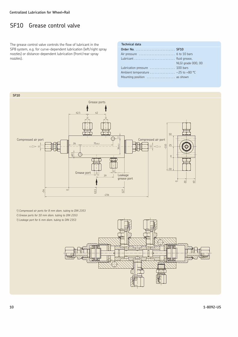
Order No. . . . . . . . . . . . . . . . . . . . . . . . . . SF10Air pressure . . . . . . . . . . . . . . . . . . . . . . . 6 to 10 barsLubricant . . . . . . . . . . . . . . . . . . . . . . . . . . fluid grease,
NLGI grade 000, 00Lubrication pressure . . . . . . . . . . . . . . . . 100 barsAmbient temperature . . . . . . . . . . . . . . . . –25 to +80 °CMounting position . . . . . . . . . . . . . . . . . . as shown
SF10 Grease control valve
The grease control valve controls the flow of lubricant in theSP8 system, e.g. for curve-dependent lubrication (left/right spraynozzles) or distance-dependent lubrication (front/rear spray nozzles).
SF10
1) Compressed air ports for 8 mm diam. tubing to DIN 23532) Grease ports for 10 mm diam. tubing to DIN 23533) Leakage port for 6 mm diam. tubing to DIN 2353
Grease ports
Compressed air port Compressed air port
Grease portLeakagegrease port
Centralized Lubrication for Wheel+Rail
11 1-8092-US
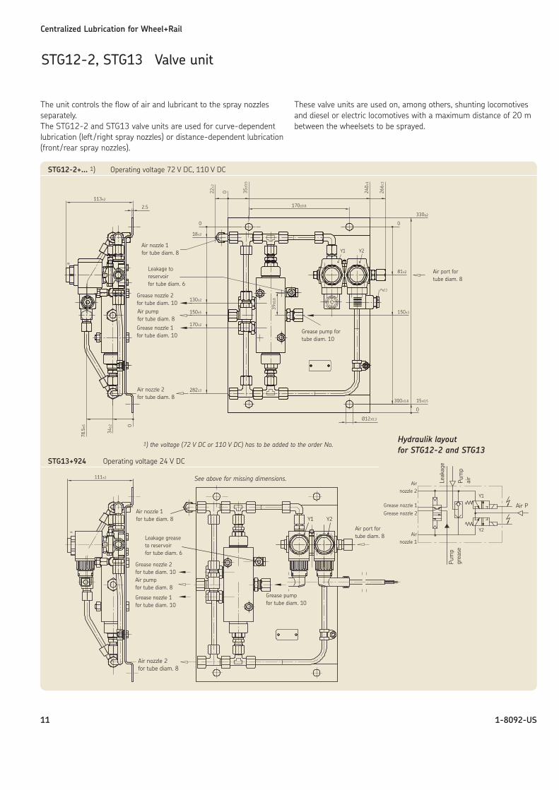
STG12-2, STG13 Valve unit
Grease nozzle 2Grease nozzle 1
The unit controls the flow of air and lubricant to the spray nozzlesseparately.The STG12-2 and STG13 valve units are used for curve-dependentlubrication (left /right spray nozzles) or distance-dependent lubrication(front/rear spray nozzles).
These valve units are used on, among others, shunting locomotivesand diesel or electric locomotives with a maximum distance of 20 mbetween the wheelsets to be sprayed.
Air nozzle 1for tube diam. 8
Leakage toreservoirfor tube diam. 6
Grease nozzle 2for tube diam. 10Air pumpfor tube diam. 8
Grease nozzle 1for tube diam. 10
Air nozzle 2for tube diam. 8
Airnozzle 2
Airnozzle 1
Grease nozzle 1Grease nozzle 2
Leak
age
Pum
pgr
ease
Pum
pai
r
Air P
Grease pump fortube diam. 10
Air port fortube diam. 8
Hydraulik layoutfor STG12-2 and STG13
1) the voltage (72 V DC or 110 V DC) has to be added to the order No.
See above for missing dimensions.
STG12-2+... 1) Operating voltage 72 V DC, 110 V DC
Air port fortube diam. 8
Air nozzle 1for tube diam. 8
Leakage greaseto reservoirfor tube diam. 6
Grease pumpfor tube diam. 10
STG13+924 Operating voltage 24 V DC
Air nozzle 2for tube diam. 8
Grease nozzle 1for tube diam. 10
Air pumpfor tube diam. 8
Grease nozzle 2for tube diam. 10
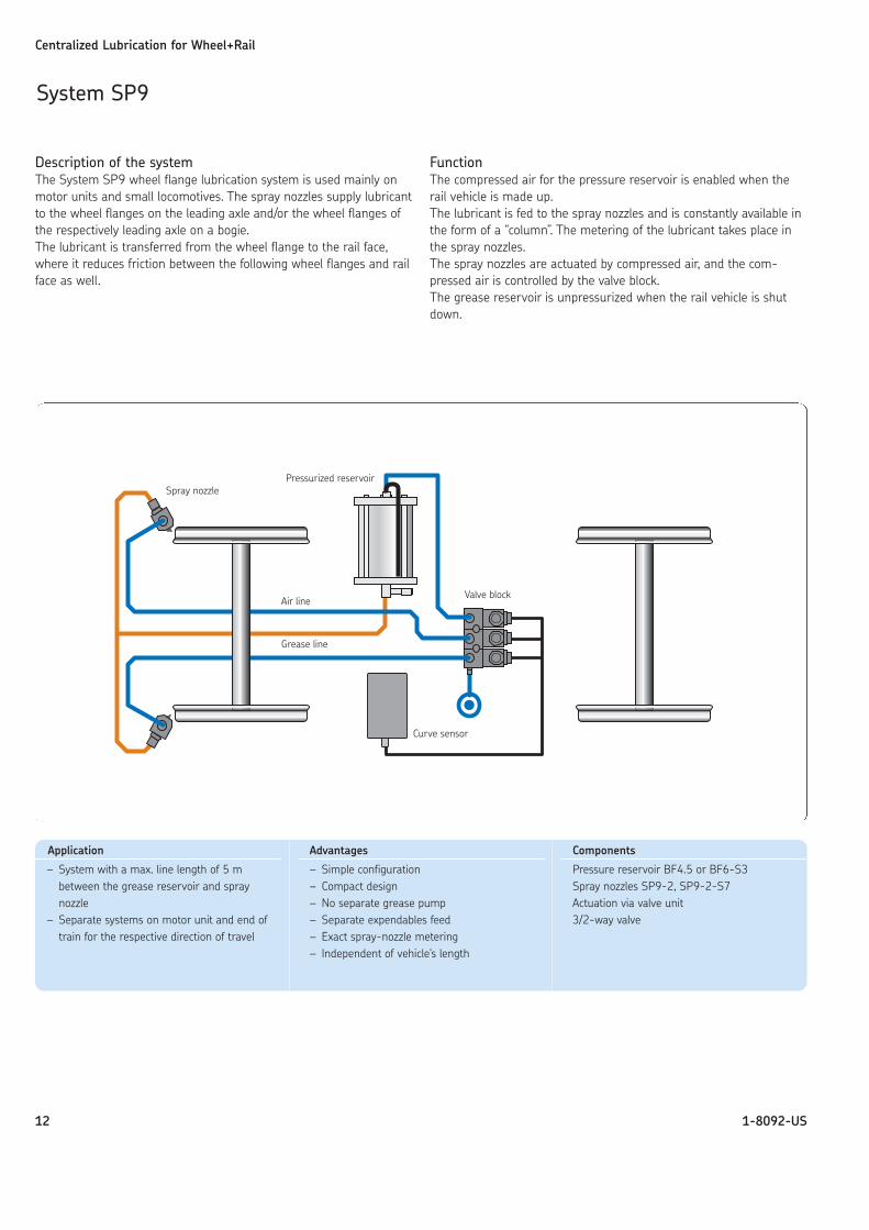
Description of the systemThe System SP9 wheel flange lubrication system is used mainly onmotor units and small locomotives. The spray nozzles supply lubricantto the wheel flanges on the leading axle and/or the wheel flanges ofthe respectively leading axle on a bogie. The lubricant is transferred from the wheel flange to the rail face,where it reduces friction between the following wheel flanges and railface as well.
FunctionThe compressed air for the pressure reservoir is enabled when therail vehicle is made up.The lubricant is fed to the spray nozzles and is constantly available inthe form of a “column”. The metering of the lubricant takes place inthe spray nozzles.The spray nozzles are actuated by compressed air, and the com-pressed air is controlled by the valve block.The grease reservoir is unpressurized when the rail vehicle is shutdown.
Centralized Lubrication for Wheel+Rail
12 1-8092-US
System SP9
Application
– System with a max. line length of 5 m between the grease reservoir and spraynozzle
– Separate systems on motor unit and end oftrain for the respective direction of travel
Advantages
– Simple configuration– Compact design– No separate grease pump– Separate expendables feed– Exact spray-nozzle metering– Independent of vehicle's length
Components
Pressure reservoir BF4.5 or BF6-S3Spray nozzles SP9-2, SP9-2-S7Actuation via valve unit3/2-way valve
Air line
Grease line
Valve block
Curve sensor
Pressurized reservoirSpray nozzle
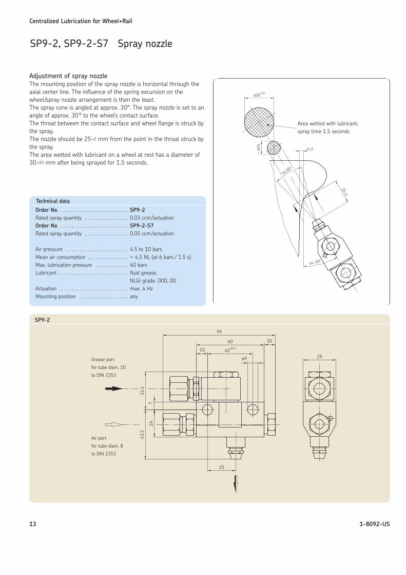
Adjustment of spray nozzleThe mounting position of the spray nozzle is horizontal through theaxial center line. The influence of the spring excursion on thewheel/spray nozzle arrangement is then the least.The spray cone is angled at approx. 30°. The spray nozzle is set to anangle of approx. 30° to the wheel’s contact surface.The throat between the contact surface and wheel flange is struck bythe spray.The nozzle should be 25 ±2 mm from the point in the throat struck bythe spray.The area wetted with lubricant on a wheel at rest has a diameter of30 ±10 mm after being sprayed for 1.5 seconds.
Centralized Lubrication for Wheel+Rail
13 1-8092-US
SP9-2, SP9-2-S7 Spray nozzle
Technical data
Order No. . . . . . . . . . . . . . . . . . . . . . . . . . SP9-2Rated spray quantity . . . . . . . . . . . . . . . . 0.03 ccm/actuationOrder No. . . . . . . . . . . . . . . . . . . . . . . . . . SP9-2-S7Rated spray quantity . . . . . . . . . . . . . . . . 0.05 ccm/actuation
Air pressure . . . . . . . . . . . . . . . . . . . . . . . 4.5 to 10 barsMean air consumption . . . . . . . . . . . . . . . ~ 4,5 NL (at 6 bars / 1.5 s)Max. lubrication pressure . . . . . . . . . . . . 40 barsLubricant . . . . . . . . . . . . . . . . . . . . . . . . . . fluid grease,
NLGI grade. 000, 00Actuation . . . . . . . . . . . . . . . . . . . . . . . . . . max. 4 HzMounting position . . . . . . . . . . . . . . . . . . any
Area wetted with lubricant;spray time 1.5 seconds
SP9-2
Grease port
for tube diam. 10
to DIN 2353
Air port
for tube diam. 8
to DIN 2353
Centralized Lubrication for Wheel+Rail
14 1-8092-US
BF4.5 Grease reservoir
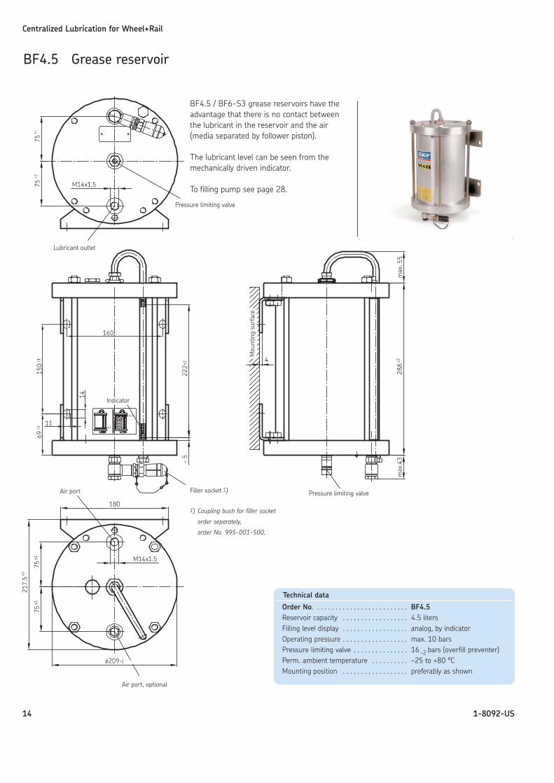
BF4.5 / BF6-S3 grease reservoirs have theadvantage that there is no contact betweenthe lubricant in the reservoir and the air(media separated by follower piston).
The lubricant level can be seen from themechanically driven indicator.
To filling pump see page 28.
Pressure limiting valve
Lubricant outlet
Indicator
Filler socket 1)
1) Coupling bush for filler socket
order separately,
order No. 995-001-500.
Pressure limiting valve
Mou
ntin
g su
rfac
e
Air port
Air port, optional
Technical data
Order No. . . . . . . . . . . . . . . . . . . . . . . . . . BF4.5Reservoir capacity . . . . . . . . . . . . . . . . . . 4.5 litersFilling level display . . . . . . . . . . . . . . . . . . analog, by indicatorOperating pressure . . . . . . . . . . . . . . . . . . max. 10 barsPressure limiting valve . . . . . . . . . . . . . . . 16–2 bars (overfill preventer)Perm. ambient temperature . . . . . . . . . . –25 to +80 °CMounting position . . . . . . . . . . . . . . . . . . preferably as shown
Centralized Lubrication for Wheel+Rail
151-8092-US
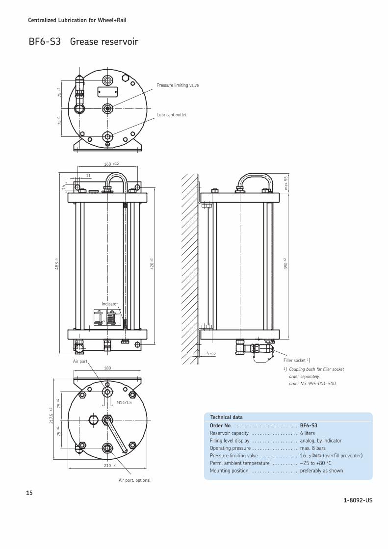
BF6-S3 Grease reservoir
Pressure limiting valve
Lubricant outlet
Air port Filler socket 1)
1) Coupling bush for filler socket
order separately,
order No. 995-001-500.
Air port, optional
Technical data
Order No. . . . . . . . . . . . . . . . . . . . . . . . . . BF6-S3Reservoir capacity . . . . . . . . . . . . . . . . . . 6 litersFilling level display . . . . . . . . . . . . . . . . . . analog, by indicatorOperating pressure . . . . . . . . . . . . . . . . . . max. 8 barsPressure limiting valve . . . . . . . . . . . . . . . 16–2 bars (overfill preventer)Perm. ambient temperature . . . . . . . . . . –25 to +80 °CMounting position . . . . . . . . . . . . . . . . . . preferably as shown
Indicator
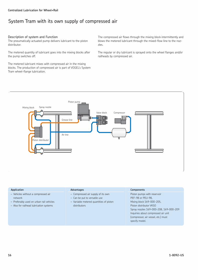
Description of system and FunctionThe pneumatically actuated pump delivers lubricant to the piston distributor.
The metered quantity of lubricant goes into the mixing blocks afterthe pump switches off.
The metered lubricant mixes with compressed air in the mixingblocks. The production of compressed air is part of VOGEL’s SystemTram wheel-flange lubrication.
The compressed air flows through the mixing block intermittently andblows the metered lubricant through the mixed-flow line to the noz-zles.
The regular or dry lubricant is sprayed onto the wheel flanges and/orrailheads by compressed air.
Centralized Lubrication for Wheel+Rail
16 1-8092-US
System Tram with its own supply of compressed air
Mixing block Spray nozzle
Piston distributor
Piston pump
CompressorValve block
Application
– Vehicles without a compressed airnetwork
– Preferably used on urban rail vehicles– Also for railhead lubrication systems
Advantages
– Compressed air supply of its own– Can be put to versatile use– Variable metered quantities of piston
distributors
Components
Piston pumps with reservoirPEF-98 or PEU-98, Mixing block 169-000-205, Piston distributor VKSOSpray nozzles 169-000-208, 169-000-209Inquiries about compressed air unit(compressor, air vessel, etc.) mustspecify model.
Grease line
Air line
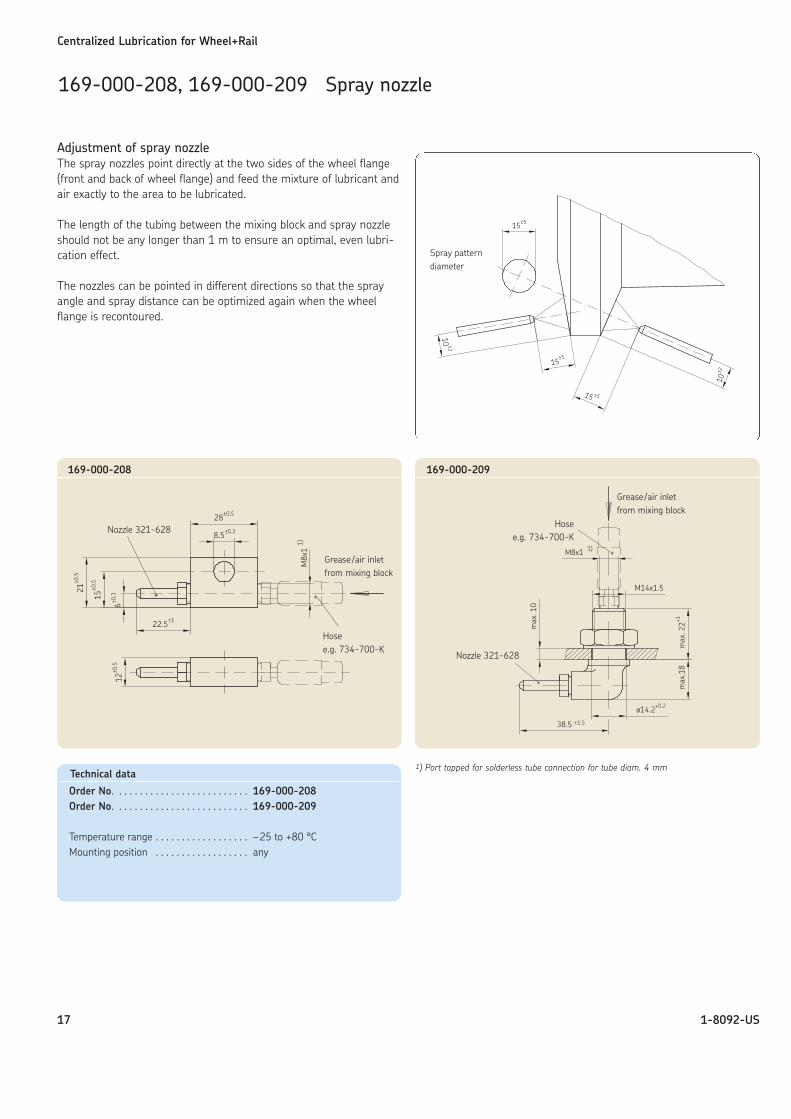
Adjustment of spray nozzle The spray nozzles point directly at the two sides of the wheel flange(front and back of wheel flange) and feed the mixture of lubricant andair exactly to the area to be lubricated.
The length of the tubing between the mixing block and spray nozzleshould not be any longer than 1 m to ensure an optimal, even lubri-cation effect.
The nozzles can be pointed in different directions so that the sprayangle and spray distance can be optimized again when the wheelflange is recontoured.
Centralized Lubrication for Wheel+Rail
17 1-8092-US
169-000-208, 169-000-209 Spray nozzle
Technical data
Order No. . . . . . . . . . . . . . . . . . . . . . . . . . 169-000-208Order No. . . . . . . . . . . . . . . . . . . . . . . . . . 169-000-209
Temperature range . . . . . . . . . . . . . . . . . . –25 to +80 °CMounting position . . . . . . . . . . . . . . . . . . any
Spray patterndiameter
Nozzle 321-628
Hosee.g. 734-700-K
Grease/air inletfrom mixing block
169-000-208 169-000-209
Nozzle 321-628
1) Port tapped for solderless tube connection for tube diam. 4 mm
Grease/air inletfrom mixing block
Hosee.g. 734-700-K
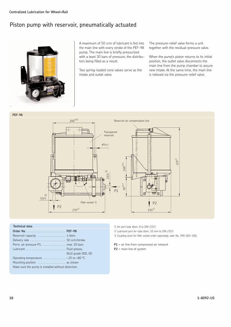
A maximum of 50 ccm of lubricant is fed intothe main line with every stroke of the PEF-98pump. The main line is briefly pressurizedwith a least 30 bars of pressure, the distribu-tors being filled as a result.
Two spring-loaded cone valves serve as theintake and outlet valve.
The pressure-relief valve forms a unittogether with the residual-pressure valve.
When the pump's piston returns to its initialposition, the outlet valve disconnects themain line from the pump chamber to assurenew intake. At the same time, the main lineis relieved via the pressure-relief valve.
Centralized Lubrication for Wheel+Rail
18 1-8092-US
Piston pump with reservoir, pneumatically actuated
Transparentreservoir
Filler socket 3)
Reservoir air compensation line
PEF-98
1) Air port tube diam. 8 to DIN 23532) Lubricant port for tube diam. 10 mm to DIN 23533) Coupling bush for filler socket order separately, oder No. 995-001-500.
P1 = air line from compressed air networkP2 = main line of system
Technical data
Order No. . . . . . . . . . . . . . . . . . . . . . . . . . PEF-98Reservoir capacity . . . . . . . . . . . . . . . . . . 4 litersDelivery rate . . . . . . . . . . . . . . . . . . . . . . . 50 ccm/strokePerm. air pressure P1. . . . . . . . . . . . . . . . max. 10 barsLubricant . . . . . . . . . . . . . . . . . . . . . . . . . . Fluid grease,
NLGI grade 000, 00Operating temperature . . . . . . . . . . . . . . –25 to +80 °CMounting position . . . . . . . . . . . . . . . . . . as shownMake sure the pump is installed without distortion.
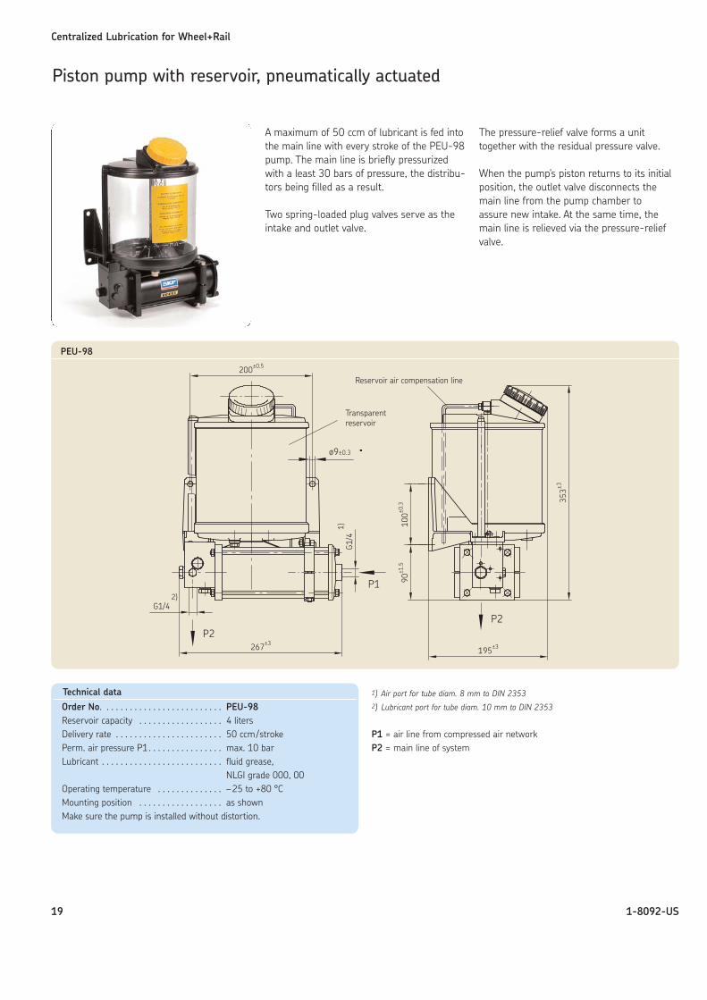
A maximum of 50 ccm of lubricant is fed intothe main line with every stroke of the PEU-98pump. The main line is briefly pressurizedwith a least 30 bars of pressure, the distribu-tors being filled as a result.
Two spring-loaded plug valves serve as theintake and outlet valve.
The pressure-relief valve forms a unittogether with the residual pressure valve.
When the pump's piston returns to its initialposition, the outlet valve disconnects themain line from the pump chamber to assure new intake. At the same time, themain line is relieved via the pressure-reliefvalve.
Centralized Lubrication for Wheel+Rail
19 1-8092-US
Piston pump with reservoir, pneumatically actuated
Transparentreservoir
Reservoir air compensation line
PEU-98
1) Air port for tube diam. 8 mm to DIN 23532) Lubricant port for tube diam. 10 mm to DIN 2353
P1 = air line from compressed air networkP2 = main line of system
Technical data
Order No. . . . . . . . . . . . . . . . . . . . . . . . . . PEU-98Reservoir capacity . . . . . . . . . . . . . . . . . . 4 litersDelivery rate . . . . . . . . . . . . . . . . . . . . . . . 50 ccm/strokePerm. air pressure P1. . . . . . . . . . . . . . . . max. 10 barLubricant . . . . . . . . . . . . . . . . . . . . . . . . . . fluid grease,
NLGI grade 000, 00Operating temperature . . . . . . . . . . . . . . –25 to +80 °CMounting position . . . . . . . . . . . . . . . . . . as shownMake sure the pump is installed without distortion.
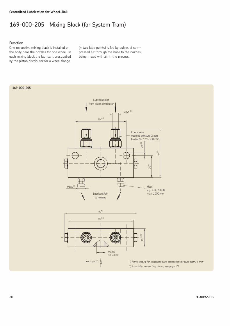
FunctionOne respective mixing black is installed onthe body near the nozzles for one wheel. Ineach mixing block the lubricant presuppliedby the piston distributor for a wheel flange
(= two lube points) is fed by pulses of com-pressed air through the hose to the nozzles,being mixed with air in the process.
Centralized Lubrication for Wheel+Rail
20 1-8092-US
169-000-205 Mixing Block (for System Tram)
Lubricant inletfrom piston distributor
Check valveopening pressure 2 bars(order No. 161-300-099)
Hosee.g. 734-700-Kmax. 1000 mmLubricant /air
to nozzles
Air input *)
12.5 deep
1) Ports tapped for solderless tube connection for tube diam. 4 mm
*) Associated connecting pieces, see page 29
169-000-205
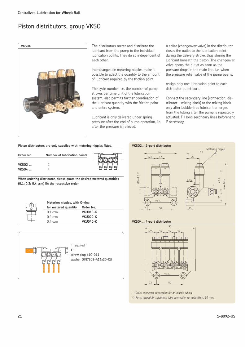
The distributors meter and distribute thelubricant from the pump to the individuallubrication points. They do so independent ofeach other.
Interchangeable metering nipples make itpossible to adapt the quantity to the amountof lubricant required by the friction point.
The cycle number, i.e. the number of pumpstrokes per time unit of the lubrication system, also permits further coordination ofthe lubricant quantity with the friction pointand entire system.
Lubricant is only delivered under springpressure after the end of pump operation, i.e.after the pressure is relieved.
A collar (changeover valve) in the distributorcloses the outlet to the lubrication pointduring the delivery stroke, thus storing thelubricant beneath the piston. The changeovervalve opens the outlet as soon as the pressure drops in the main line, i.e. when the pressure relief valve of the pump opens.
Assign only one lubrication point to each distributor outlet port.
Connect the secondary line (connection: dis-tributor - mixing block) to the mixing blockonly after bubble-free lubricant emergesfrom the tubing after the pump is repeatedlyactuated. Fill long secondary lines beforehandif necessary.
Centralized Lubrication for Wheel+Rail
21 1-8092-US
Piston distributors, group VKSO
VKSO4
Piston distributors are only supplied with metering nipples fitted.
Order No. Number of lubrication points
VKSO2 … 2VKSO4 … 4
When ordering distributor, please quote the desired metered quantities(0.1; 0.2; 0.4 ccm) iin the respective order.
Metering nipples, with O-ringfor metered quantity Order No.0.1 ccm VKU010-K0.2 ccm VKU020-K0.4 ccm VKU040-K
If required:←←screw plug 410-011 washer DIN7603-A16x20-CU
VKSO2... 2-port distributor
VKSO4... 4-port distributor
Metering nipple
1) Quick connector connection for ø4 plastic tubing.2) Ports tapped for solderless tube connection for tube diam. 10 mm.
Centralized Lubrication for Wheel+Rail
22 1-8092-US
CS200 Curve sensor control unit
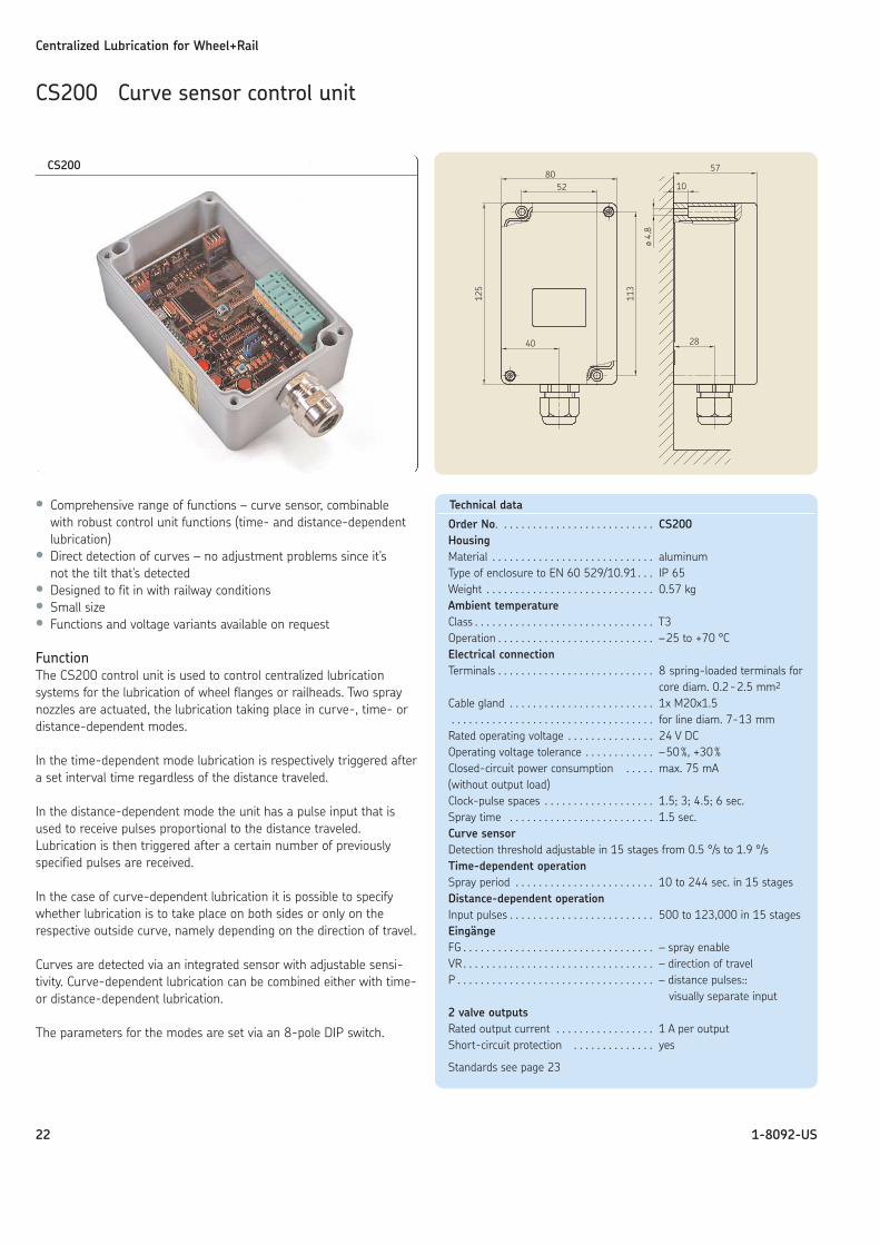
• Comprehensive range of functions – curve sensor, combinablewith robust control unit functions (time- and distance-dependentlubrication)
• Direct detection of curves – no adjustment problems since it'snot the tilt that's detected
• Designed to fit in with railway conditions• Small size• Functions and voltage variants available on request
FunctionThe CS200 control unit is used to control centralized lubrication systems for the lubrication of wheel flanges or railheads. Two spraynozzles are actuated, the lubrication taking place in curve-, time- ordistance-dependent modes.
In the time-dependent mode lubrication is respectively triggered aftera set interval time regardless of the distance traveled.
In the distance-dependent mode the unit has a pulse input that isused to receive pulses proportional to the distance traveled.Lubrication is then triggered after a certain number of previouslyspecified pulses are received.
In the case of curve-dependent lubrication it is possible to specifywhether lubrication is to take place on both sides or only on therespective outside curve, namely depending on the direction of travel.
Curves are detected via an integrated sensor with adjustable sensi-tivity. Curve-dependent lubrication can be combined either with time-or distance-dependent lubrication.
The parameters for the modes are set via an 8-pole DIP switch.
CS200
Technical data
Order No. . . . . . . . . . . . . . . . . . . . . . . . . . . CS200HousingMaterial . . . . . . . . . . . . . . . . . . . . . . . . . . . . aluminumType of enclosure to EN 60 529/10.91 . . . IP 65Weight . . . . . . . . . . . . . . . . . . . . . . . . . . . . . 0.57 kgAmbient temperatureClass . . . . . . . . . . . . . . . . . . . . . . . . . . . . . . . T3Operation . . . . . . . . . . . . . . . . . . . . . . . . . . . –25 to +70 °CElectrical connectionTerminals . . . . . . . . . . . . . . . . . . . . . . . . . . . 8 spring-loaded terminals for
core diam. 0.2-2.5 mm2
Cable gland . . . . . . . . . . . . . . . . . . . . . . . . . 1x M20x1.5. . . . . . . . . . . . . . . . . . . . . . . . . . . . . . . . . . . for line diam. 7-13 mm
Rated operating voltage . . . . . . . . . . . . . . . 24 V DCOperating voltage tolerance . . . . . . . . . . . . –50%, +30%Closed-circuit power consumption . . . . . max. 75 mA(without output load)Clock-pulse spaces . . . . . . . . . . . . . . . . . . . 1.5; 3; 4.5; 6 sec.Spray time . . . . . . . . . . . . . . . . . . . . . . . . . 1.5 sec.Curve sensorDetection threshold adjustable in 15 stages from 0.5 °/s to 1.9 °/sTime-dependent operationSpray period . . . . . . . . . . . . . . . . . . . . . . . . 10 to 244 sec. in 15 stagesDistance-dependent operationInput pulses . . . . . . . . . . . . . . . . . . . . . . . . . 500 to 123,000 in 15 stagesEingängeFG . . . . . . . . . . . . . . . . . . . . . . . . . . . . . . . . . – spray enableVR. . . . . . . . . . . . . . . . . . . . . . . . . . . . . . . . . – direction of travelP . . . . . . . . . . . . . . . . . . . . . . . . . . . . . . . . . . – distance pulses::
visually separate input2 valve outputsRated output current . . . . . . . . . . . . . . . . . 1 A per outputShort-circuit protection . . . . . . . . . . . . . . yes
Standards see page 23
Centralized Lubrication for Wheel+Rail
23 1-8092-US
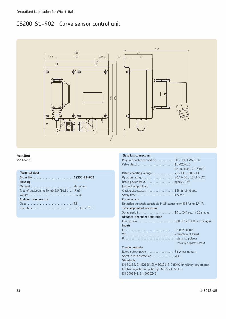
CS200-S1+902 Curve sensor control unit
Functionsee CS200
Technical data
Order No. . . . . . . . . . . . . . . . . . . . . . . . . . . CS200-S1+902HousingMaterial . . . . . . . . . . . . . . . . . . . . . . . . . . . . aluminumType of enclosure to EN 60 529/10.91 . . . IP 65Weight . . . . . . . . . . . . . . . . . . . . . . . . . . . . . 1.6 kgAmbient temperatureClass . . . . . . . . . . . . . . . . . . . . . . . . . . . . . . . T3Operation . . . . . . . . . . . . . . . . . . . . . . . . . . . –25 to +70 °C
Electrical connectionPlug and socket connection . . . . . . . . . . . HARTING HAN 15 DCable gland . . . . . . . . . . . . . . . . . . . . . . . . 1x M20x1.5
for line diam. 7-13 mmRated operating voltage . . . . . . . . . . . . . . 72 V DC …110 V DCOperating range . . . . . . . . . . . . . . . . . . . 50.4 V DC …137.5 V DCRated power input . . . . . . . . . . . . . . . . . . . approx. 8 W(without output load)Clock-pulse spaces . . . . . . . . . . . . . . . . . . 1.5; 3; 4.5; 6 sec.Spray time . . . . . . . . . . . . . . . . . . . . . . . . 1.5 sec.Curve sensorDetection threshold adustable in 15 stages from 0.5 °/s to 1.9 °/sTime-dependent operationSpray period . . . . . . . . . . . . . . . . . . . . . . . 10 to 244 sec. in 15 stagesDistance-dependent operationInput pulses . . . . . . . . . . . . . . . . . . . . . . . . 500 to 123,000 in 15 stagesInputsFG . . . . . . . . . . . . . . . . . . . . . . . . . . . . . . . . – spray enableVR. . . . . . . . . . . . . . . . . . . . . . . . . . . . . . . . – direction of travelP . . . . . . . . . . . . . . . . . . . . . . . . . . . . . . . . . – distance pulses:
visually separate input2 valve outputsRated output power . . . . . . . . . . . . . . . . . 36 W per outputShort-circuit protection . . . . . . . . . . . . . yesStandardsEN 50153, EN 50155, ENV 50121-3-2 (EMC for railway equipment);Electromagnetic compatibility EMC 89/336/EEC:EN 50081-1, EN 50082-2
Centralized Lubrication for Wheel+Rail
24 1-8092-US
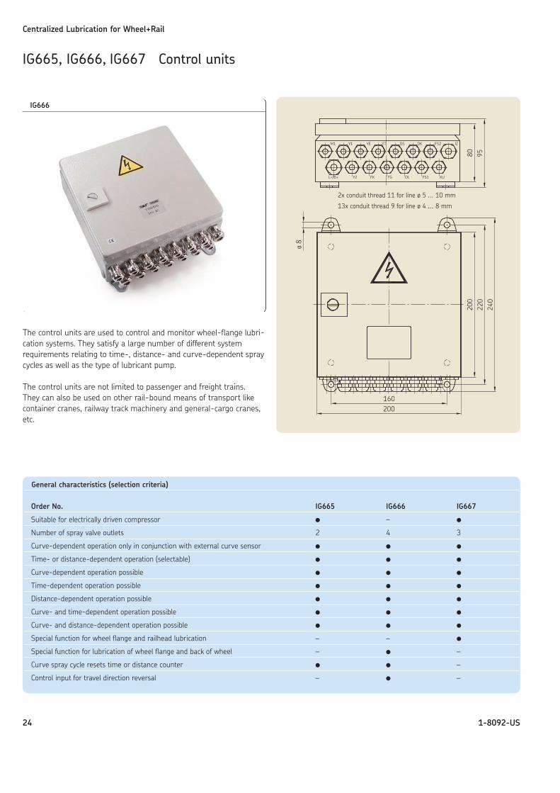
IG665, IG666, IG667 Control units
The control units are used to control and monitor wheel-flange lubri-cation systems. They satisfy a large number of different systemrequirements relating to time-, distance- and curve-dependent spraycycles as well as the type of lubricant pump.
The control units are not limited to passenger and freight trains. They can also be used on other rail-bound means of transport likecontainer cranes, railway track machinery and general-cargo cranes,etc.
General characteristics (selection criteria)
Order No. IG665 IG666 IG667
Suitable for electrically driven compressor � – �
Number of spray valve outlets 2 4 3
Curve-dependent operation only in conjunction with external curve sensor � � �
Time- or distance-dependent operation (selectable) � � �
Curve-dependent operation possible � � �
Time-dependent operation possible � � �
Distance-dependent operation possible � � �
Curve- and time-dependent operation possible � � �
Curve- and distance-dependent operation possible � � �
Special function for wheel flange and railhead lubrication – – �
Special function for lubrication of wheel flange and back of wheel – � –
Curve spray cycle resets time or distance counter � � –
Control input for travel direction reversal – � –
IG666
2x conduit thread 11 for line ø 5 ... 10 mm
13x conduit thread 9 for line ø 4 ... 8 mm
Centralized Lubrication for Wheel+Rail
25 1-8092-US
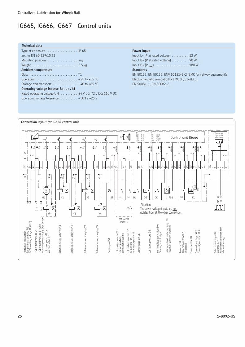
IG665, IG666, IG667 Control units
Connection layout for IG666 control unit
Technical data
Type of enclosure . . . . . . . . . . . . . . . . . . IP 65acc. to EN 60 529/10.91Mounting position . . . . . . . . . . . . . . . . . . anyWeight . . . . . . . . . . . . . . . . . . . . . . . . . . . . 3.5 kgAmbient temperatureClass . . . . . . . . . . . . . . . . . . . . . . . . . . . . . T1Operation . . . . . . . . . . . . . . . . . . . . . . . . . –25 to +55 °CStorage and transport . . . . . . . . . . . . . . . –40 to +85 °COperating voltage inputse B+, L+ / MRated operating voltage UN . . . . . . . . . . 24 V DC; 72 V DC; 110 V DCOperating voltage tolerance . . . . . . . . . . . –30% / +25%
Power inputInput L+ (P at rated voltage) . . . . . . . . . . 12 WInput B+ (P at rated voltage) . . . . . . . . . . 90 WInput B+ (Pmax.) . . . . . . . . . . . . . . . . . . . . 180 WStandardsEN 50153, EN 50155, ENV 50121-3-2 (EMC for railway equipment);Electromagnetic compatibility EMC 89/336/EEC:EN 50081-1, EN 50082-2.
Technical data
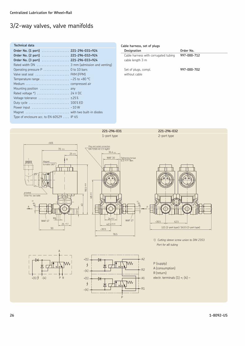
Order No. (1 port) . . . . . . . . . . . . . . . . . 221-296-031+924Order No. (2 port) . . . . . . . . . . . . . . . . . 221-296-032+924Order No. (3 port) . . . . . . . . . . . . . . . . . 221-296-033+924Rated width DN . . . . . . . . . . . . . . . . . . . . 3 mm (admission and venting)Operating pressure P . . . . . . . . . . . . . . . . 0 to 10 barsValve seat seal . . . . . . . . . . . . . . . . . . . . . FKM (FPM)Temperature range . . . . . . . . . . . . . . . . . . –25 to +80 °CMedium . . . . . . . . . . . . . . . . . . . . . . . . . . . compressed airMounting position . . . . . . . . . . . . . . . . . . anyRated voltage *) . . . . . . . . . . . . . . . . . . . . 24 V DCVoltage tolerance . . . . . . . . . . . . . . . . . . . ±25%Duty cycle . . . . . . . . . . . . . . . . . . . . . . . . . 100% EDPower input . . . . . . . . . . . . . . . . . . . . . . . ~10 WMagnet . . . . . . . . . . . . . . . . . . . . . . . . . . . with two built-in diodesType of enclosure acc. to EN 60529 . . . . IP 65
Centralized Lubrication for Wheel+Rail
26 1-8092-US
1) Cutting sleeve screw union to DIN 2353
Port for ø8 tubing
Cable harness, set of plugsDesignation Order No.Cable harness with corrugated tubing 997-000-712cable length 3 m
Set of plugs, compl. 997-000-702without cable
3/2-way valves, valve manifolds
221-296-031 221-296-0321-port type 2-port type
P (supply)A (consumption)R (return)electr. terminals (1) +; (4) –
Centralized Lubrication for Wheel+Rail
27 1-8092-US
3/2-way valves, valve manifolds
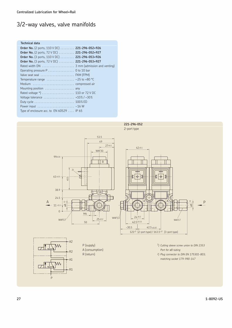
1) Cutting sleeve screw union to DIN 2353
Port for ø8 tubing2) Plug connector to DIN EN 175301-803;
matching socket 179-990-147
P (supply)A (consumption)R (return)
Technical data
Order No. (2 ports, 110 V DC) . . . . . . . . . 221-296-052+926Order No. (2 ports, 72 V DC) . . . . . . . . . . 221-296-052+927Order No. (3 ports, 110 V DC) . . . . . . . . . 221-296-053+926Order No. (3 ports, 72 V DC) . . . . . . . . . . 221-296-053+927Rated width DN . . . . . . . . . . . . . . . . . . . . . 3 mm (admission and venting)Operating pressure P . . . . . . . . . . . . . . . . . 0 to 10 barValve seat seal . . . . . . . . . . . . . . . . . . . . . . FKM (FPM)Temperature range . . . . . . . . . . . . . . . . . . –25 to +80 °CMedium . . . . . . . . . . . . . . . . . . . . . . . . . . . compressed airMounting position . . . . . . . . . . . . . . . . . . . anyRated voltage *) . . . . . . . . . . . . . . . . . . . . . 110 or 72 V DCVoltage tolerance . . . . . . . . . . . . . . . . . . . . +10% / –30%Duty cycle . . . . . . . . . . . . . . . . . . . . . . . . . . 100% EDPower input . . . . . . . . . . . . . . . . . . . . . . . . ~16 WType of enclosure acc. to EN 60529 . . . . IP 65
221-296-0522-port type
Centralized Lubrication for Wheel+Rail
28 1-8092-US
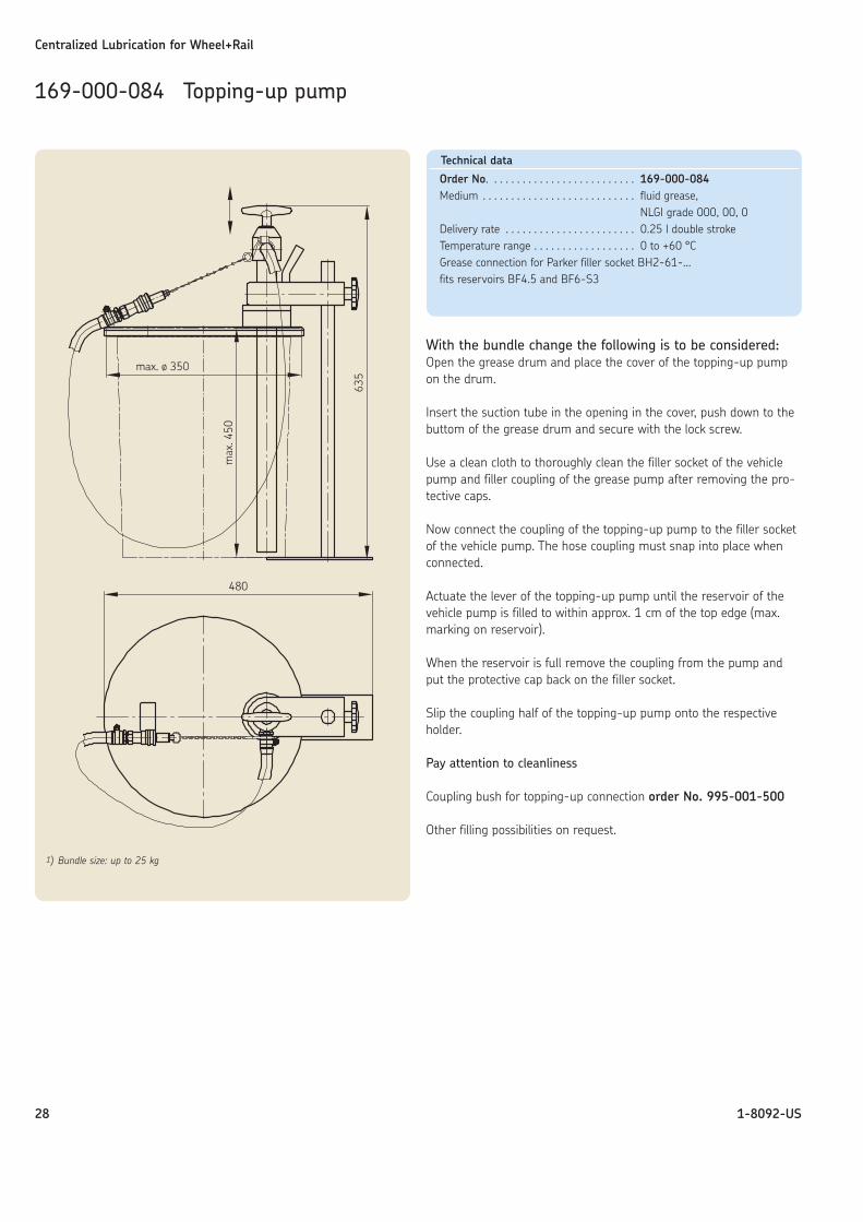
With the bundle change the following is to be considered:Open the grease drum and place the cover of the topping-up pumpon the drum.
Insert the suction tube in the opening in the cover, push down to thebuttom of the grease drum and secure with the lock screw.
Use a clean cloth to thoroughly clean the filler socket of the vehiclepump and filler coupling of the grease pump after removing the pro-tective caps.
Now connect the coupling of the topping-up pump to the filler socketof the vehicle pump. The hose coupling must snap into place whenconnected.
Actuate the lever of the topping-up pump until the reservoir of thevehicle pump is filled to within approx. 1 cm of the top edge (max.marking on reservoir).
When the reservoir is full remove the coupling from the pump andput the protective cap back on the filler socket.
Slip the coupling half of the topping-up pump onto the respectiveholder.
Pay attention to cleanliness
Coupling bush for topping-up connection order No. 995-001-500
Other filling possibilities on request.
169-000-084 Topping-up pump
1) Bundle size: up to 25 kg
Technical data
Order No. . . . . . . . . . . . . . . . . . . . . . . . . . 169-000-084Medium . . . . . . . . . . . . . . . . . . . . . . . . . . . fluid grease,
NLGI grade 000, 00, 0Delivery rate . . . . . . . . . . . . . . . . . . . . . . . 0.25 l double strokeTemperature range . . . . . . . . . . . . . . . . . . 0 to +60 °CGrease connection for Parker filler socket BH2-61-…fits reservoirs BF4.5 and BF6-S3
Centralized Lubrication for Wheel+Rail
29 1-8092-US
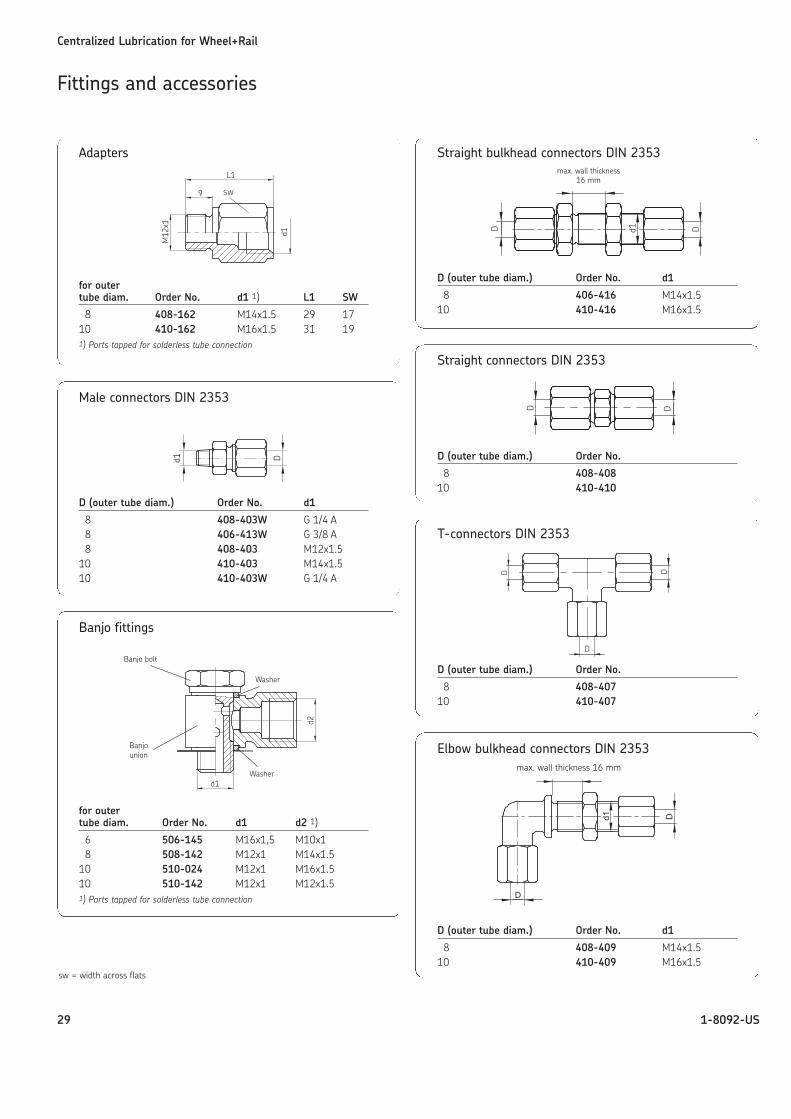
Straight bulkhead connectors DIN 2353
D (outer tube diam.) Order No. d1
8 406-416 M14x1.510 410-416 M16x1.5
Fittings and accessories
Straight connectors DIN 2353
D (outer tube diam.) Order No.
8 408-40810 410-410
max. wall thickness16 mm
Elbow bulkhead connectors DIN 2353
D (outer tube diam.) Order No. d1
8 408-409 M14x1.510 410-409 M16x1.5
max. wall thickness 16 mm
T-connectors DIN 2353
D (outer tube diam.) Order No.
8 408-40710 410-407
Male connectors DIN 2353
D (outer tube diam.) Order No. d1
8 408-403W G 1/4 A8 406-413W G 3/8 A8 408-403 M12x1.5
10 410-403 M14x1.510 410-403W G 1/4 A
Adapters
for outertube diam. Order No. d1 1) L1 SW
8 408-162 M14x1.5 29 1710 410-162 M16x1.5 31 191) Ports tapped for solderless tube connection
Banjo fittings
for outertube diam. Order No. d1 d2 1)
6 506-145 M16x1,5 M10x18 508-142 M12x1 M14x1.5
10 510-024 M12x1 M16x1.510 510-142 M12x1 M12x1.51) Ports tapped for solderless tube connection
Banjo bolt
Washer
Washer
Banjounion
sw = width across flats
Centralized Lubrication for Wheel+Rail
30 1-8092-US
Fittings and accessories
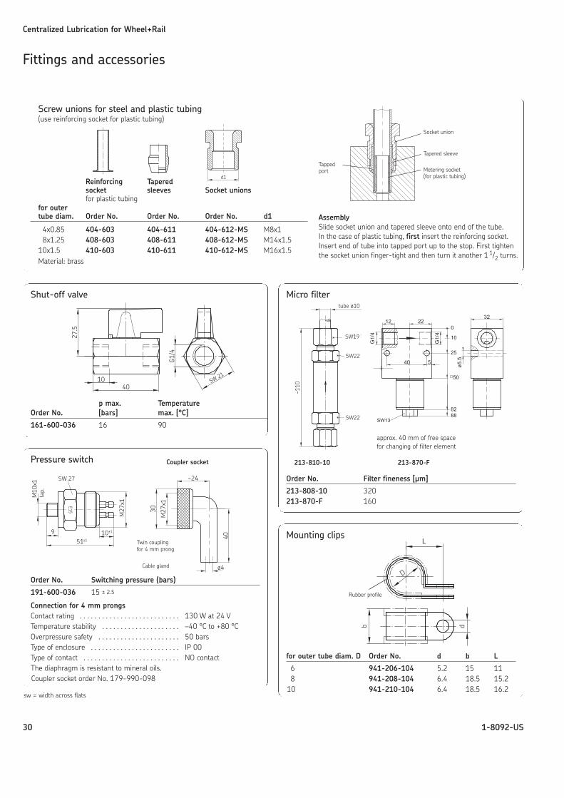
Micro filter
Order No. Filter fineness [μm]
213-808-10 320213-870-F 160
Mounting clips
for outer tube diam. D Order No. d b L
6 941-206-104 5.2 15 118 941-208-104 6.4 18.5 15.2
10 941-210-104 6.4 18.5 16.2
Rubber profile
Shut-off valve
p max. TemperatureOrder No. [bars] max. [°C]
161-600-036 16 90
Pressure switch
Order No. Switching pressure (bars)
191-600-036 15 ± 2.5
Connection for 4 mm prongsContact rating . . . . . . . . . . . . . . . . . . . . . . . . . . . 130 W at 24 VTemperature stability . . . . . . . . . . . . . . . . . . . . . –40 °C to +80 °COverpressure safety . . . . . . . . . . . . . . . . . . . . . . 50 barsType of enclosure . . . . . . . . . . . . . . . . . . . . . . . . IP 00Type of contact . . . . . . . . . . . . . . . . . . . . . . . . . . NO contactThe diaphragm is resistant to mineral oils.Coupler socket order No. 179-990-098
213-810-10 213-870-F
approx. 40 mm of free spacefor changing of filter element
tube ø10
Screw unions for steel and plastic tubing(use reinforcing socket for plastic tubing)
Reinforcing Taperedsocket sleeves Socket unionsfor plastic tubing
for outertube diam. Order No. Order No. Order No. d1
4x0.85 404-603 404-611 404-612-MS M8x18x1.25 408-603 408-611 408-612-MS M14x1.5
10x1.5 410-603 410-611 410-612-MS M16x1.5Material: brass
AssemblySlide socket union and tapered sleeve onto end of the tube.In the case of plastic tubing, first insert the reinforcing socket.Insert end of tube into tapped port up to the stop. First tightenthe socket union finger-tight and then turn it another 1 1/2 turns.
Tappedport Metering socket
(for plastic tubing)
Tapered sleeve
Socket union
Coupler socket
Cable gland
Twin coupling for 4 mm prong
sw = width across flats
tap.
Centralized Lubrication for Wheel+Rail
31 1-8092-US
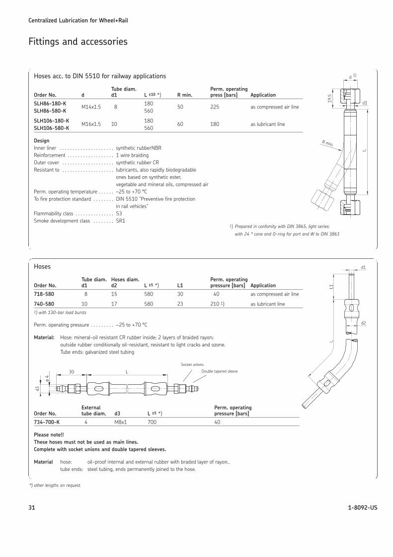
Hoses acc. to DIN 5510 for railway applications
Tube diam. Perm. operatingOrder No. d d1 L ±10 *) R min. press [bars] Application
SLH86-180-K M14x1.5 8 180 50 225 as compressed air lineSLH86-580-K 560
SLH106-180-K M16x1.5 10 180 60 180 as lubricant lineSLH106-580-K 560
DesignInner liner . . . . . . . . . . . . . . . . . . . . . synthetic rubberNBRReinforcement . . . . . . . . . . . . . . . . . . 1 wire braidingOuter cover . . . . . . . . . . . . . . . . . . . . synthetic rubber CRResistant to . . . . . . . . . . . . . . . . . . . . lubricants, also rapidly biodegradable
ones based on synthetic ester,vegetable and mineral oils, compressed air
Perm. operating temperature . . . . . . –25 to +70 °CTo fire protection standard . . . . . . . . DIN 5510 “Preventive fire protection
in rail vehicles”Flammability class . . . . . . . . . . . . . . . S3Smoke development class . . . . . . . . SR1
Hoses
Tube diam. Hoses diam. Perm. operatingOrder No. d1 d2 L ±5 *) L1 pressure [bars] Application
718-580 8 15 580 30 40 as compressed air line
740-580 10 17 580 23 210 1) as lubricant line1) with 130-bar load bursts
Perm. operating pressure . . . . . . . . . –25 to +70 °C
Material: Hose: mineral-oil resistant CR rubber inside; 2 layers of braided rayon;outside rubber conditionally oil-resistant, resistant to light cracks and ozone.Tube ends: galvanized steel tubing
External Perm. operatingOrder No. tube diam. d3 L ±5 *) pressure [bars]
734-700-K 4 M8x1 700 40
Please note!!These hoses must not be used as main lines.Complete with socket unions and double tapered sleeves.
Material hose: oil-proof internal and external rubber with braded layer of rayon..tube ends: steel tubing, ends permanently joined to the hose.
1) Prepared in confomity with DIN 3865, light series:
with 24 ° cone and O-ring for port and W to DIN 3861
Double tapered sleeve
Socket unions
*) other lengths on request.
Fittings and accessories
Centralized Lubrication for Wheel+Rail
32 1-8092-US
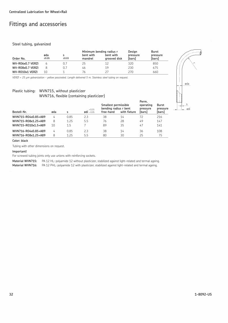
Steel tubing, galvanized
Minimum bending radius r Design Burstøda s bent with bent with pressure pressure
Order No. ±0.05 ±0.03 mandrel grooved disk [bars] [bars]
WV-RO6x0.7 VERZI 6 0.7 25 12 320 850WV-RO8x0.7 VERZI 8 0.7 46 19 230 675WV-RO10x1 VERZI 10 1 76 27 270 660
VERZI = 25 μm galvanization - yellow passivated. Length delivered 5 m. Stainless steel tubing on request.
Plastic tubing: WVN715, without plasticizerWVN716, flexible (containing plasticizer)
Perm.Smallest permissible operating Burst
+ 0.15 bending radius r bent pressure pressureBestell-Nr. øda s ødi – 0.05 free-hand with fixture [bars] [bars]
WVN715-RO4x0.85+A89 4 0.85 2.3 38 14 72 216WVN715-RO8x1.25+A89 8 1.25 5.5 76 28 49 147WVN715-RO10x1.5+A89 10 1.5 7 89 35 47 141
WVN716-RO4x0.85+A89 4 0.85 2.3 38 14 36 108WVN716-RO8x1.25+A89 8 1.25 5.5 80 30 25 75
Color: black
Tubing with other dimensions on request.
Important!For screwed tubing joints only use unions with reinforcing sockets.
Material WVN715: PA 12 HL: polyamide 12 without plasticizer, stabilized against light-related and termal ageing. Material WVN716: PA 12 PHL: polyamide 12 with plasticizer, stabilized against light-related and termal ageing.
Fittings and accessories
Centralized Lubrication for Wheel+Rail
33 1-8092-US
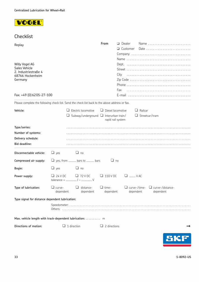
Checklist
Please complete the following check list. Send the check list back to the above address or fax.
Vehicle: ❑❑ Electric locomotive ❑❑ Diesel locomotive ❑❑ Railcar
❑❑ Subway/underground ❑❑ Interurban train / ❑❑ Streetcar / tramrapid rail system
Type/series: . . . . . . . . . . . . . . . . . . . . . . . . . . . . . . . . . . . . . . . . . . . . . . . . . . . . . . . . . . . . . . . . . . . . . . . . . . . . . . . . . . . .
Number of systems: . . . . . . . . . . . . . . . . . . . . . . . . . . . . . . . . . . . . . . . . . . . . . . . . . . . . . . . . . . . . . . . . . . . . . . . . . . . . . . . . . . . .
Delivery schedule: . . . . . . . . . . . . . . . . . . . . . . . . . . . . . . . . . . . . . . . . . . . . . . . . . . . . . . . . . . . . . . . . . . . . . . . . . . . . . . . . . . . .
Bid deadline: . . . . . . . . . . . . . . . . . . . . . . . . . . . . . . . . . . . . . . . . . . . . . . . . . . . . . . . . . . . . . . . . . . . . . . . . . . . . . . . . . . . .
Disconnectable vehicle: ❑❑ yes ❑❑ no
Compressed air supply: ❑❑ yes, from ........... bars to ........... bars ❑❑ no
Bogie: ❑❑ yes ❑❑ no
Power supply: ❑❑ 24 V DC ❑❑ 72 V DC ❑❑ 110 V DC ❑❑ ......... V ACtolerance + ............... / – ............... V
Type of lubrication: ❑❑ curve- ❑❑ distance- ❑❑ time- ❑❑ curve-/ time- ❑❑ curve-/distance-dependent dependent dependent dependent dependent
Type signal for distance dependent lubrication:
Speedometer: . . . . . . . . . . . . . . . . . . . . . . . . . . . . . . . . . . . . . . . . . . . . . . . . . . . . . . . . . . . . . . . . . . . . . . . . . . . . . . . . . . Others: . . . . . . . . . . . . . . . . . . . . . . . . . . . . . . . . . . . . . . . . . . . . . . . . . . . . . . . . . . . . . . . . . . . . . . . . . . . . . . . . . . . . . . .
Max. vehicle length with track-dependent lubrication: . . . . . . . . . . m
Directions of motion: ❑❑ 1 direction ❑❑ 2 directions ��
Willy Vogel AGSales Vehicle2. Industriestraße 468766 HockenheimGermany
Fax: +49 (0) 6205-27-100
From ❑ Dealer Name . . . . . . . . . . . . . . . . . . . . . . . . . . ❑ Customer Date . . . . . . . . . . . . . . . . . . . . . . . . . . . Company . . . . . . . . . . . . . . . . . . . . . . . . . . . . . . . . . . . . Name . . . . . . . . . . . . . . . . . . . . . . . . . . . . . . . . . . . . . . . Dept. . . . . . . . . . . . . . . . . . . . . . . . . . . . . . . . . . . . . . . . Street . . . . . . . . . . . . . . . . . . . . . . . . . . . . . . . . . . . . . . . City . . . . . . . . . . . . . . . . . . . . . . . . . . . . . . . . . . . . . . . Zip Code . . . . . . . . . . . . . . . . . . . . . . . . . . . . . . . . . . . . . Phone . . . . . . . . . . . . . . . . . . . . . . . . . . . . . . . . . . . . . . . Fax . . . . . . . . . . . . . . . . . . . . . . . . . . . . . . . . . . . . . . . E-mail . . . . . . . . . . . . . . . . . . . . . . . . . . . . . . . . . . . . . .
Replay
Principal scheme of system layout
Centralized Lubrication for Wheel+Rail
34 1-8092-US
Driving speed: Maximum speed . . . . . . . . . . . . . . . . . . . . . . . . . . . . . . . . . . . . . . . . . . . . . . . . . . . . . . . . . . . . . . km/h
Operational speed . . . . . . . . . . . . . . . . . . . . . . . . . . . . . . . . . . . . . . . . . . . . . . . . . . . . . . . . . . . . . km/h
Competitors (Wheel-flange lubrication): Company . . . . . . . . . . . . . . . . . . . . . . . . . . . . . . . . . . . . . . . . . . . . . . . . . . . . . . . . . . . . . . . . . . . . . . . . . .
Special requirements/options: . . . . . . . . . . . . . . . . . . . . . . . . . . . . . . . . . . . . . . . . . . . . . . . . . . . . . . . . . . . . . . . . . . . . . . . . . . . . . . . . . . . . . . . . . . . . . . . . . . . . . . . . . . . . . . . . . . . . . . . . . . . . . . . . . . . . . . . . . . . . . . . . . . . . . . . . . . . . . . . . . . . . . . . . . . . . . . . . . . . . . . . . . . . . . . . . . . . . . . . . . . . . . . . . . . . . . . . . . . . . . . . . . . . . . . . . . . . . . . . . . . . . . . . . .
Photographs/catalogues of rail vehicles?❑❑ yes (attached) ❑❑ yes (will be supplied ❑❑ no

35 1-8092-US
Notice!All products from VOGEL may be used only for their intended pur-pose. If operating instructions are supplied together with the pro-ducts, the provisions and information therein of specific relevance tothe equipment must be observed as well.In particular, we call your attention to the fact that hazardous mate-rials of any kind, especially the materials classified as hazardous byEC Directive 67/548/EEC, Article 2, Par. 2, may only be filled intoVOGEL centralized lubrication systems and components and deliveredand/or distributed with the same after consultation with and writtenapproval from VOGEL.All products manufactured by VOGEL are not approved for use inconjunction with gases, liquefied gases, pressurized gases in solutionand fluids with a vapor pressure exceeding normal atmosphericpressure (1013 mbars) by more than 0.5 bar at their maximumpermissible temperature.
Competence Center for Railhead Lubrication
Willy Vogel AktiengesellschaftA company of the SKF GroupHockenheim plant2. Industriestrasse 4 · 68766 Hockenheim · GermanyTel. +49 (0)6205 27-0 · Fax +49 (0)6205 [email protected] · www.vogelag.com · www.skf.com
Order No. 1-8092-US (Subject to change without notice ! 09/2006))
This brochure was presented by:


