
Edinburgh Central Heating Installation - Platinum Heating Services 07738 498 799

Central Heating CookerOil
Instructions for Use,Installation and ServicingFor use in GB, IE (Great Britain and Eire)
C601972 Issue 4 (December 2007)
IMPORTANTThe front and top of this cooker will become hot whilst in operation. It is therefore recommended that a suitable guard should be
used for the protection of young children, the elderly or infirm.Please read these instructions carefully before installation or use.
Keep them in a safe place for future reference and when servicing the cooker.The commissioning sheet found at the end of the User Sections of these instructions should be completed by the installer.
This appliance has been certified for use in countries other than those stated. To install this appliance in these countries, it is essential to obtain the translated instructions and in some cases the appliance will require modification. Contact Redfyre for further information.
2
CONTENTS
Appliance Commissioning Checklist 3
USER INSTRUCTIONS 4
Cooker Features and Control 5 Oven Cooking Guide 9 Care of the Cooker 10 User Cooker Fault Finding 11 After Sales Service Information 12
INSTALLATION INSTRUCTIONS 13
Technical Specification 13 Site Requirements 14 Oil Supply 15 Site Requirements 22 General 17 Regulations 17 Health and Safety 17 Oil Systems 19 Flue Systems 23 Water Systems 25 Open Systems 26 Electrical Systems 27 CD10 Form 31
SERVICING INSTRUCTIONS 32
Technical Specifications 32 Boiler Flue ways 33 Cooker Flue ways 35 Priming and Adjusting of Pumps 38
Technical Data 39 Nozzle Output 39 Guide to Fault Finding 41 Fault Finding 42 Oil Cooker Burner Spare Parts 43 Cooker Spares 44
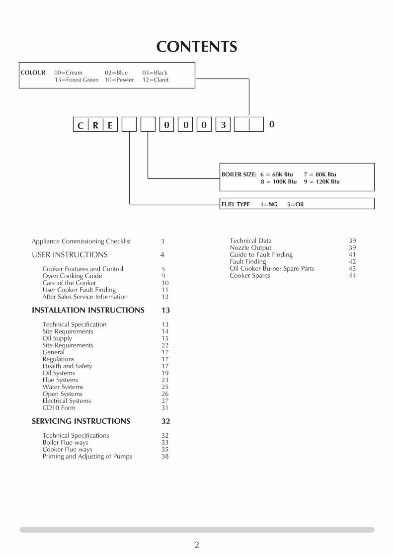
C R E
BOILER SIZE: 6 = 60K Btu 7 = 80K Btu 8 = 100K Btu 9 = 120K Btu
FUEL TYPE 1=NG 5=Oil
COLOUR 00=Cream 02=Blue 03=Black 13=Forest Green 10=Pewter 12=Claret
00 00 3

3
FLUE CHECK PASS FAIL
1. Flue is correct for appliance
2. Flue flow test
3. Spillage test
4. Chimney flue draught reading mm wg
OIL CHECK
1. Are all joints and connections airtight?
2. Check KBB operation
3. Check burner operation
4. CD10 and CD11 completed and returned
APPLIANCE COMMISSIONING CHECKLIST
Dealer . . . . . . . . . . . . . . . . . . . . . . . . . . . . . . . . . . . . . . . . . . . . . . . . . . . . . . . . . . . . . . . . . . . . .
. . . . . . . . . . . . . . . . . . . . . . . . . . . . . . . . . . . . . . . . . . . . . . . . . . . . . . . . . . . . . . . . . . . . . . . . . . . . . . .
. . . . . . . . . . . . . . . . . . . . . . . . . . . . . . . . . . . . . . . . . . . . . . . . . . . . . . . . . . . . . . . . . . . . . . . . . . . . . . .
Contact No. . . . . . . . . . . . . . . . . . . . . . . . . . . . . . . . . . . . . . . . . . . . . . . . . . . . . . . . . . . . . . .
Date of Purchase . . . . . . . . . . . . . . . . . . . . . . . . . . . . . . . . . . . . . . . . . . . . . . . . . . . . . . .
Model No. . . . . . . . . . . . . . . . . . . . . . . . . . . . . . . . . . . . . . . . . . . . . . . . . . . . . . . . . . . . . . . . .
Serial No. . . . . . . . . . . . . . . . . . . . . . . . . . . . . . . . . . . . . . . . . . . . . . . . . . . . . . . . . . . . . . . . . .
Gas Type . . . . . . . . . . . . . . . . . . . . . . . . . . . . . . . . . . . . . . . . . . . . . . . . . . . . . . . . . . . . . . . . . .
Installation Company . . . . . . . . . . . . . . . . . . . . . . . . . . . . . . . . . . . . . . . . . . . . . . . .
. . . . . . . . . . . . . . . . . . . . . . . . . . . . . . . . . . . . . . . . . . . . . . . . . . . . . . . . . . . . . . . . . . . . . . . . . . . . . . . .
. . . . . . . . . . . . . . . . . . . . . . . . . . . . . . . . . . . . . . . . . . . . . . . . . . . . . . . . . . . . . . . . . . . . . . . . . . . . . . . .
Engineer . . . . . . . . . . . . . . . . . . . . . . . . . . . . . . . . . . . . . . . . . . . . . . . . . . . . . . . . . . . . . . . . . . .
Contact No. . . . . . . . . . . . . . . . . . . . . . . . . . . . . . . . . . . . . . . . . . . . . . . . . . . . . . . . . . . . . . . .
OFTEC Reg No. . . . . . . . . . . . . . . . . . . . . . . . . . . . . . . . . . . . . . . . . . . . . . . . . . . . . . . . . . .
Date of Installation . . . . . . . . . . . . . . . . . . . . . . . . . . . . . . . . . . . . . . . . . . . . . . . . . . . .
IMPORTANT NOTICEExplain the operation of the appliance to the end user, hand the completed instructions to them for safe keeping. The following
information will be required when making any guaranteed claims.
DEALER AND INSTALLER INFORMATION
This product is guaranteed for 2 years from the date of installation, as set out in the terms and conditions of sale between Redfyre and your local Redfyre dealer. This guarantee will be invalid, to the extent permitted by law, if the above Appliance Commissioning Checklist is not fully completed by the installer and available for inspection by a Redfyre engineer. The guarantee will only be valid during the second year, to the extent permitted by law, if the annual service recommended in the Instructions for Use has been completed by an OFTEC registered engineer, and a copy of the service visit report is available for inspection by a Redfyre engineer.

4
USER INSTRUCTIONS
1. DESCRIPTION
1.1 Congratulations, you are now the proud owner of the new Redfyre central heating cooker capable of providing full central heating and domestic hot water. As manufacturers we are proud of the features and quality of construction of all our cookers.
2. GENERAL
2.1 As manufacturers and suppliers of cookers and heating products we take care to ensure these products are designed and constructed to meet all safety requirements when properly used and installed. To this end, our products are thoroughly examined and tested before delivery.
2.2 These Instructions explain the features of your new cooker and how you can achieve the best results. They describe cleaning, maintenance, installation and servicing. Please read these instructions with care so you can enjoy cooking and can maintain your cooker to give many years of service.
2.3 A qualified installer must install, commission, service or carry out any remedial work, i.e. electrical fault finding.
2.4 The cooker must not be altered in any way. A cooker that is incorrectly installed, altered in any way or not serviced can invalidate approval of the appliance, its warranty and may affect your statutory rights
2.5 The cooker must be operated by adults; children should not play with or near the cooker and a suitable guard used for protection of young children and the infirm.
2.6 Parts of the cooker become very hot when in use (e.g. hotplates and ovens) and remain hot for a long period after use. Take great care when using the cooker and use oven gloves whenever appropriate.
2.7 This Redfyre cooker is designed for cooking, domestic hot water and central heating and must not be used for other purposes.
2.8 Make sure you use stable saucepans and always position handles away from the edge of the hotplate.
2.9 Do not place combustible materials onto the hotplate surfaces even when the cooker is off.
2.10 Do not spray aerosols in the vicinity of this appliance while it is operating.
2.11 Do not cover the outlet on the top rear splash back cover.2.12 Do not allow clothes, furnishings or any combustible
material to come into contact with any flue pipe.
3. RUNNING-IN
3.1 The new surface coating on your Redfyre cooker "burns off" to create a harmless odour during its first hours of use. This smell disappears after a short period but if it persists ask your installer for advice. You should open windows or doors to keep the room well ventilated until the odour disappears.
4. VENTILATION
4.1 Heat and moisture are produced by oil range cookers. Ensure the kitchen is well ventilated.
4.2 You may need to open a window or increase mechanical ventilation during prolonged use of the cooker.
4.3 Air for combustion is taken in through the cooker’s burner door. DO NOT shut off or block this door or any additional air vents fitted by your installer in any compartment or to the outside.
4.4 Any purpose-provided ventilation must be periodically checked to ensure it is free from obstruction.
5. SERVICING & SPARE PARTS
5.1 The cooker must be serviced every 12 months by a qualified gas engineer. In all correspondence, always quote the Model and Serial Number found on the data badge inside the bottom left door.
5.2 You must turn off your cooker 12 hours before servicing. Your cooker cannot be serviced while it is hot.
5.3 All Redfyre products must be serviced annually by a competent person using approved spare parts available from Redfyre.
6. FROST PROTECTION
6.1 During severe cold weather, if the DHW boiler is out of use for a lengthy period, we recommend you drain down the whole system to avoid the risk of freezing, but frequent draining is not recommended, especially in hard water areas where this may lead to a build up of scale inside the boiler.
6.2 For short periods of absence, leave the cooker operating at a low thermostat setting.

5
USER INSTRUCTIONSCOOKER FEATURES AND CONTROLS
The cooker has two ovens to be used as and when you want: the programmable main oven and the baking oven beneath. The main oven works like a conventional oven being controlled by it own thermostat. This thermostat also controls the rest of the appliance. This oven reaches a roasting temperature in approximately 20-25 minutes from cold, or in less time if it has already been in use. The baking oven works by heat conduction.
Two pressure jet burners give you complete control of the appliance; one for central heating and one for cooking.
1. MAIN OVEN
1.1 The main oven operates in similar fashion to a conventional oven, reaching high temperatures in approximately 20-25 minutes from cold. It has its own programmer and a thermostatic control that also serves the rest of the appliance.
Position shelves on runners as follows:1.2 Top Shelf - used to grill meats, vegetables and so on, or
brown dishes such as gratins under heat radiating from the roof.
1.3 Second Shelf down – used for roasting potatoes, cooking scones and so on. Covered dishes and hot puddings can be quickly reheated here.
1.4 Middle Shelf – used for roasting meats, jacket potatoes, pastry, bread rolls, loaves and pizzas.
1.5 Grid Shelf on oven floor – used for large loaves of bread and slower roasts (e.g. pork, poultry).
1.6 Direct onto oven floor – for pastry, tarts and pies or crisping up the bottom of bread loaves. The frying pan can be heated on the floor before transferring to the hotplates and then transferred back to the oven floor to finish off. This helps to keep the area around the hotplate clean and free.
1.7 Spillages inside this oven are automatically burnt off and can be easily removed with a brush.
2. BAKING OVEN
2.1 This oven operates at approximately 100°C lower than the main oven. If the main oven is set to 200°C, then the lower oven is simply used as a warming oven.
2.2 Use the moderate heat of this oven for baking cakes and biscuits and cooking fish. Slow, long-cooking dishes are often started on one of the hotplates, then transferred to this oven.
3. HOTPLATE
3.1 The dog bone hotplate is large enough to support seven various sized saucepans. The heat distribution is graduated across the hotplate, the left side becoming hottest first. The higher the oven temperature setting, the hotter the hotplates.
3.2 Two insulated lids conserve heat and should be closed when the hotplate is not in use.
3.3 When hot, wear gloves to remove the decorative centre cover.
4. CONTROL PANEL
4.1 One control panel is behind the top left door of the cooker.
1
AR1825
Cooker timer
Cooker thermostat
Overheat warning
Boiler/oven operating
Boiler thermostat
Reset
It has: a) a Cooker Timer you must program b) two Thermostats: – Boiler Thermostat (controlling the temperature of the
Central Heating water) – Cooker Thermostat (controlling the temperature of the
oven and other cooking surfaces) Both the oven and boiler have orange neon indicators that
are lit until the oven or boiler have reached their set temperature.
c) two Overheat Thermostats you might need to reset. For safety, there are two manual overheat thermostats for
the oven and boiler inside the top left door. Each overheat thermostat has a red neon indicator. If these are lit you must reset each thermostat. The reset buttons spring out if overheating occurs.
For the oven:• PressintheredresetbuttonbeneaththeredindicatorFor the boiler:• Pressinthebrowncross-shapedbuttonbeneaththered
indicatorIf frequent resetting is required, contact your distributor; the appliance may need servicing.
4.2 A further control panel is behind the lower left door. It has: a) Two Reset buttons: one for the Cooker and one for the
Boiler Burner

6
6. SWITCHING OFF
6.1 If you want to switch off the appliance for short periods: - For the boiler: • TurnalltheexternalcontrolstoOFFandturntheboiler
thermostat to OFF- For the cooker: • TurnthecookerthermostatandprogrammertoOFF
6.2 To switch off the appliance for longer periods:• Turnallexternalandinternalcontrolstooffandswitch
off the electricity supply to the appliance.
See the previous section for information on Frost Protection
7. COOKER PROGRAM
You have a choice of either a manual or automatic setting to turn your boiler ON and OFF.
Make sure the cooker thermostat is demanding heat if you want the cooker to fire up after setting the program.
Setting the Cooker Timer
7.1 When the appliance is first powered-up you need to remove the cover protecting the Timer buttons. To start the Timer:• Pressandholddownthefourbuttonsshowningreyin
the following diagram, 2.
2
AR1624
Re-setting the Time of Day
7.2 Remove the cover protecting the programming buttons• PressPROGforProgrammingMode
You see a time displayed. The colon dividing hours and minutes does not flash.
• PressandreleasethePlus(+)orMinus(-)buttononceto
change the time in one minute increments. Ifyouholddownthe+or-buttonthetimechangesinten
minute increments.
USER INSTRUCTIONSCOOKER FEATURES AND CONTROLS
These buttons are lit if either the cooker or boiler burners are extinguished by some kind of blockage or restriction.
For either the cooker or boiler:• Pressthelitbuttontore-firetheburner,ensuringthe
appropriate thermostat is demanding heat
You must contact your distributor if either of these burners continually needs resetting.
1
AR1826Boiler burner reset switch Cooker burner reset switch
Blocked flue resetBlocked flue light
b) a Blocked Flue Reset Button and red indicator at top right corner of panel
This light is lit if there is a problem with the flue system. It can be reset:
• Presstheresetbuttonbesidethelight If this happens more than twice, call a service engineer to
check the flue for blockages, refer to Section 9.
5. LIGHTING THE BURNERS
Oven Burner
5.1 Lighting the oven burner is a fully automatic process:• EnsuretheprogrammerisinONmodeandthe
programmer’s neon is lit• Turntheoventhermostattothedesiredtemperature.
The oven’s orange indicator lights up and remains lit until the correct temperature is reached.
Boiler Burner
5.2 Lighting the boiler is a fully automatic process:• MakesureanyexternalcontrolsareONanddemanding
heat• Turntheboilerthermostattothedesiredtemperature

7
3
AR1625
• PressandreleasethePlus(+)orMinus(-)buttononcetochange the time in one minute increments
• Pressandholdthe+or-buttonthetimechangesintenminute increments
Factory Settings
7.2 The appliance has 3 pre-settings for each day to automatically switch the cooker ON and OFF which you can alter to suit your lifestyle. A morning afternoon and evening Event is set:
Event 1 ON = 06:30 am OFF = 08:30 am Event 2 ON = 12:00 pm OFF = 02:00 pm Event 2 ON = 05:00 pm OFF = 10:30 pm
Adjusting Factory Settings
7.3 To change the factory settings:• PressPROG You will see the following display:
4
AR1626
The Event Number is displayed at the top left. • PressandreleasethePlus(+)orMinus(-)buttononce
to change the time in one minute increments • Pressandholdthe+or-buttonthetimechangesin
ten minute increments • PressPROGagaintoselectthetimeatwhichtheboiler
switches OFF for this event • PressandreleasethePlus(+)orMinus(-)buttononce
to change the time in one minute increments.
5
AR1627
• PressandreleasethePlus(+)orMinus(-)buttononceto change the time in one minute increments.
• Pressandholdthe+or-buttonthetimechangesinten minute increments
The Event number automatically changes after setting each Event.
7.4 To change the factory settings for Events 2 and 3, repeat the procedure at 7.3.
• PressPROGagaintoreturntotheRUNmode •SelectAUTOifyounowanttoruntheprogram • ReplacethecoverprotectingtheTimerbuttons
Choosing Manual or Automatic Settings
7.5 • UsetheSELECTbuttontochoosebetween: ON Run continuously OFF Off continuously AUTO Follows programme ALL DAY Turns first programmed event ON
and turns OFF at the end of last programmed event.
System Overrides
7.6 • UsetheADVor+1HRbuttontochooseanoverride: ADV Advancesappliancetothenextevent 1HR Adds 1 further hour onto the current event.
7.7 Any Timer settings are retained for 14 days following a power failure, after which the appliance goes to sleep mode. If this happens, you must reset the Timer when power is restored, see 7.1 above.
USER INSTRUCTIONSCOOKER FEATURES AND CONTROLS

8
USER INSTRUCTIONSCOOKER FEATURES AND CONTROLS
8. CENTRAL HEATING
8.1 The heating or hot water are regulated simply by turning the Boiler thermostat to the temperature you want.
• MakesureyourexternalProgrammerisONandaskingfor heat before adjusting the thermostat
1
AR1825
Boiler thermostat
9. BLOCKED FLUE
9.1 This is a blocked flue sensing device. This is an important safety device to prevent the products of combustion entering the room due to a flue problem. Under no circumstances must this device be put out of operation whilst the cooker is in use.
9.2 When this device operates it will turn both burners off and the red neon illuminates. It is not possible to relight the appliance for approximately 30 minutes after which time the reset button must be pressed.
9.3 In the event of repeated activation of the blocked flue device the chimney / flue problem must be investigated and corrective action taken immediately.
9.4 Access to the reset button is achieved by opening the control lower left-hand door and pressing the red reset button.

9
USER INSTRUCTIONSOVEN COOKING GUIDE
2. POULTRY
2.1 Cook Poultry or Game on a trivet in a roasting tin to prevent the meat stewing in its own juice. Add on time where there is stuffing.
Setting Shelf Approx TimeChicken - 170°C 3 20-25minper500g+20- 25 minTurkey -slow 170°C 3 20-25minper500g+20-(under 4.5kg) 25 min -quick 200°C 3 15-20minper500g+15- 20 minTurkey -slow 170°C 3 30-35minper500g+30-(over 4.5kg) 35 min -quick 200°C 3 25-30minper500g+25- 30 minPorkorVeal -slow 170°C 3 35-40minper500g+35- 40 min -quick 200°C 3 25-30minper500g+25- 30 min
3. CASSEROLES
3.1 Sear or seal meat over a high heat before adding to a casserole and bring liquid to boil if required for the casserole.
Setting Shelf Approx TimeTop Oven 140-150°C 3 Hours according to recipeOven-baked Fish 180°C 3 According to size cut, preparation and recipe
4. CAKES
Setting Shelf Approx TimeRich Fruit Cake 140-150°C 4 Approximately 45 min per 500g of mixture (7-8") 2-3 hrsVictoriaSandwich 180°C 3Queens cakes 180-190°C 2 (2 trays) 3 15-25 minScones 200°C 2 10-15 min
5. PASTRIES
Setting Shelf Approx TimeShortcrust 200°C 4 According to recipeFlaky 220°C 2 According to recipe Rough puff 220°C 2 According to recipePuff pastry 220°C 2 According to recipe
Heat storage cookers have a reputation for producing very fine cooking but if you are new to cooking on this type of stove you need to understand the difference between this cooker and a conventional cooker. Once the cooker has reached a desired temperature, there is no quick way of reducing the heat; you cannot simply turn a knob to lower the temperature. To keep dishes from boiling over or over-cooking, you must move your dish from one position on a hotplate (or in an oven) to another. If you have not used this type of cooker before you may need to think about your approach to cooking. This section gives you some typical examples and guidelines to help you adjust.
From cold, your top right oven should reach a Roasting Temperature in approximately half an hour.
1. MEAT
1.1 Roast meat cooked inside this type of heat storage cooker retains its size and shape and rarely needs extra cooking fat. There are two methods:• QuickRoastat200oC for superior cuts• SlowRoastat170oC for coarser cuts
We recommend searing or sealing an inferior cut at high temperature for 20/30 minutes before reducing the heat. You can rest the meat for a few minutes at the end of cooking by putting it in the lower oven to settle the juices and allow for easy carving.
1.2 To calculate cooking times, always consider the shape of a joint as well as its weight. A narrow joint cooks faster than a solid, even-shaped joint.
1.3 The oven settings and cooking times below are given as a guide only. Individual tastes may require you to adjust the settings or reposition the dish being cooked. (If temperatures seem to vary hugely to those listed, then the oven thermostat may be faulty and may need replacing.
Note: The tables below are for guidance only. Each cooker installation varies slightly.
Setting Shelf Approx TimeBeefwith -slow 170°C 3 20-25minper500g+20- bone 25 min -quick 200°C 3 15-20minper500g+15- 20 minBeefboneless -slow 170°C 3 30-35minper500g+30- 35 min -quick 200°C 3 20-25minper500g+20- 25 minLamb -slow 170°C 3 30-35minper500g+30- 35 min -quick 200°C 3 25-30minper500g+25- 30 minPorkorVeal -slow 170°C 3 35-40minper500g+35- 40 min -quick 200°C 3 25-30minper500g+25- 30 min

10
USER INSTRUCTIONS
CARE OF THE COOKER
IMPORTANT:• Neverusecaustic,citricorabrasivecleanersasthesewill
scratch or damage the surface.• Alwaystrytowipeupanyspillagesastheyhappen.• Amoresatisfactoryresultisachievedifthecookeriscool
when cleaning.• Usehotsoapywaterandaclothfortheenamel,dryingoff
with a soft cloth to avoid streaking.• Tocleaninsideovens,wirebrushcarbonstainsandvacuum
up deposits. The wire brush scratches the internal oven surface but this does not damage its natural surface. Ensure the natural surface is dry after cleaning to prevent oxidation.
Top Plate ¸ ¸ Hot Plate Dome Chrome ¸ Hot Plates ¸ ¸ Oven ¸ Chrome Shelves ¸ ¸ ¸ Oven Door ¸ Door Liner ¸ ¸ Seal ¸ Colour Parts ¸ Front ¸ Sides ¸ Doors ¸ Chrome Handles ¸ Tower Rail ¸
Nyl
on B
rush
CreamCleanerVEApproved
Wire
Bru
sh
Hot
Wat
er &
Soa
p

11
USER INSTRUCTIONSCOOKER FAULT FINDING
CO
OKE
R D
OES
NO
T ST
ART
CH
ECK
THE
FUSE
IN C
OO
KER
AND
BO
ILER
MAI
NS
SUPP
LY H
AS N
OT
BLO
WN
REPL
ACE
FUSE
IF F
USE
BLO
WS
AGAI
N C
ALL
YOU
R EN
GIN
EER
IS T
HE
CO
OKE
R PR
OG
RAM
MER
SW
ITC
HED
ON
? (N
OTE
: PR
OG
RAM
MER
WIL
L G
O T
O S
LEEP
IF
PO
WER
SU
PPLY
IS
INTE
RRU
PTED
FO
R M
ORE
TH
AN 1
4 D
AYS)
- R
EFER
TO
PRO
GRA
MM
ER
INST
RUC
TIO
NS
TO W
AKE
UP
THE
PRO
GRA
MM
ER
CH
ECK
CO
OKE
R TH
ERM
OST
AT IS
SW
ITC
HED
ON
– A
MBE
R N
EON
IS L
IT
IS T
HE
CO
OKE
R RE
SET
NEO
N L
IT?
PRES
S RE
SET
BUTT
ON
– (D
O N
OT
RESE
T M
ORE
TH
AN T
WIC
E . I
F FA
ULT
PER
SIST
S C
ALL
YOU
R EN
GIN
EER)
No
IS T
HE
CO
OKE
R BU
RNER
RES
ET B
UTT
ON
LIT
?
PRES
S RE
SET
BUTT
ON
- (D
O N
OT
RESE
T M
ORE
TH
AN T
WIC
E . I
F FA
ULT
PE
RSIS
TS C
ALL
YOU
R EN
GIN
EER)
Yes
IF B
OTH
BO
ILER
& C
OO
KER
RESE
T BU
TTO
NS
ARE
LIT,
IT M
AY B
E TH
AT
YOUHAVERUNOUTOFFUEL
Yes
Yes
Yes
No
Yes
Yes
BOIL
ER W
ILL
NO
T W
ORK
IS Y
OU
R EX
TERN
AL P
ROG
RAM
MER
CA
LLIN
G F
OR
HEA
T?
IS T
HE
BOIL
ER B
URN
ER R
ESET
BU
TTO
N L
IT?
IS T
HE
CO
OKE
R TE
MPE
RATU
RE N
EON
LIT
WH
EN T
HE
CO
OKE
R TH
ERM
OST
AT IS
TU
RNED
TO
MAX
IMU
M?
SET
EXTE
RNA
L PR
OG
RAM
MER
IS T
HE
BOIL
ER H
IGH
LIM
IT R
ESET
N
EON
LIT
ON
TH
E C
ON
TRO
L PA
NEL
?
CH
ECK
THE
FUSE
IN C
OO
KER
BOIL
ER M
AIN
S SU
PPLY
REPL
ACE
FUSE
.IF
FU
SE B
LOW
S A
GA
IN C
ALL
YOU
R EN
GIN
EER
PRES
S RE
SET
BUTT
ON
. (D
O N
OT
RESE
T M
ORE
TH
AN
TW
ICE.
IF
FAU
LT P
ERSI
STS
CA
LL Y
OU
R EN
GIN
EER)
IF B
OTH
BO
ILER
& C
OO
KER
RESE
T BU
TTO
NS
ARE
LIT
IT M
AY B
E TH
AT
YOUHAVERUNOUTOFFUEL
Yes
Yes
Yes
Yes
Yes
No
No
No
No

12
USER INSTRUCTIONSAFTER SALES SERVICE INFORMATION
1. GUIDE TO REPORTING A FAULT
1.1 A qualified Field Service Engineer is available to attend breakdown or manufacturing faults whilst this appliance is under guarantee.
1.2 A charge is made where:• OurFieldServiceEngineerfindsnofaultwiththe
appliance• Thecauseofabreakdownisoutsidetheappliance,being
part of the plumbing or heating system, including oil line or oil deficiency or other equipment not supplied by Redfyre
• Wheretheappliancefallsoutsidetheguaranteeperiod,(see Terms and Conditions)
• Theappliancehasnotbeencorrectlyinstalled,commissioned or serviced as recommended (see Commissioning, Installation and Servicing Instructions)
• Thebreakdownoccursimmediatelyafteranannualservice visit. In this instance, your appointed Service Agent must check all his work before requesting Redfyre to attend
1.3 Over 50% of all service calls are found to have no appliance fault.
1.4 In the event of an appliance fault or breakdown:Step 1: Always contact your installer or commissioning
engineer in the first instance. He must thoroughly check his work before requesting a service visit from Redfyre.
Step 2: If your appliance has developed an in-guarantee fault, your installer should contact Redfyre Service Centre for assistance.
What happens if my installer/engineer is not available?Step 3: Contact Redfyre Direct. We provide you with the
name and telephone number of our Service Agent. However, a charge can apply if the fault is not covered by the appliance guarantee (payment is requested on site by our independent Service Agent).
Note: Unauthorised invoices for attendance and repair work to this appliance by any third party are not accepted by Redfyre.
2. THE COOKER ENAMEL
2.1 Every enamelled part of your cooker is unique and has its own individual characteristics. Coloured parts may differ slightly in shading. This does not impair performance in any way and is quite normal.
IMPORTANT CUSTOMER NOTICE Cosmetic damage, stains and scratches produced by cooking
and cleaning are NOT covered by the statutory guarantee. The user MUST be aware of this before the cooker is installed and commissioned.
Refer to the Appliance Commissioning Checklist on page 1 of these Instructions for the product guarantee.

13
Model Cooker 60 80 100 120
Rated input kW 17 18.9 23.8 32.2 39.1
Rated output kW 17.6 21.9 29.3 35.2
Case Emission kW 0.5 0.8 1.0 1.0
Efficiency (NETT) 93% 92% 91% 90%
SAP Rating 88.4% 87.6% 86.2% 85.2%
Efficiency Band B B B C
Burner Minor 1 Minor 1 Minor 1 Minor 4 Minor 8
Oil pump pressure (PSI) 6.8 (100) 6.8 (100) 7.5 (110) 9.5 (140) 7.8 (115)
C02 % 11 11 11.5 12 12
Max fuel per hour – kg 1.42 1.58 2.13 2.66 3.2
INSTALLATION INSTRUCTIONSTECHNICAL SPECIFICATION
1
AR1581
AR1582
Fuel 28 sec kerosene (BS 28695)
Weight – dry kg 500
Water content – litre 38
Flow and return tappings 2 x 11/4" BSP
Test pressure 4.5 bar
Operating pressure 3 bar max
Water side resistance – mbar
10oC diff 26
12oC diff 8.3
Flue sockets – inside Flue dia. Dia.145mm 5" (125 mm)
Starting current – Amp 3.5
Running current – Amp 1.2
14
1. COOKER CLEARANCE
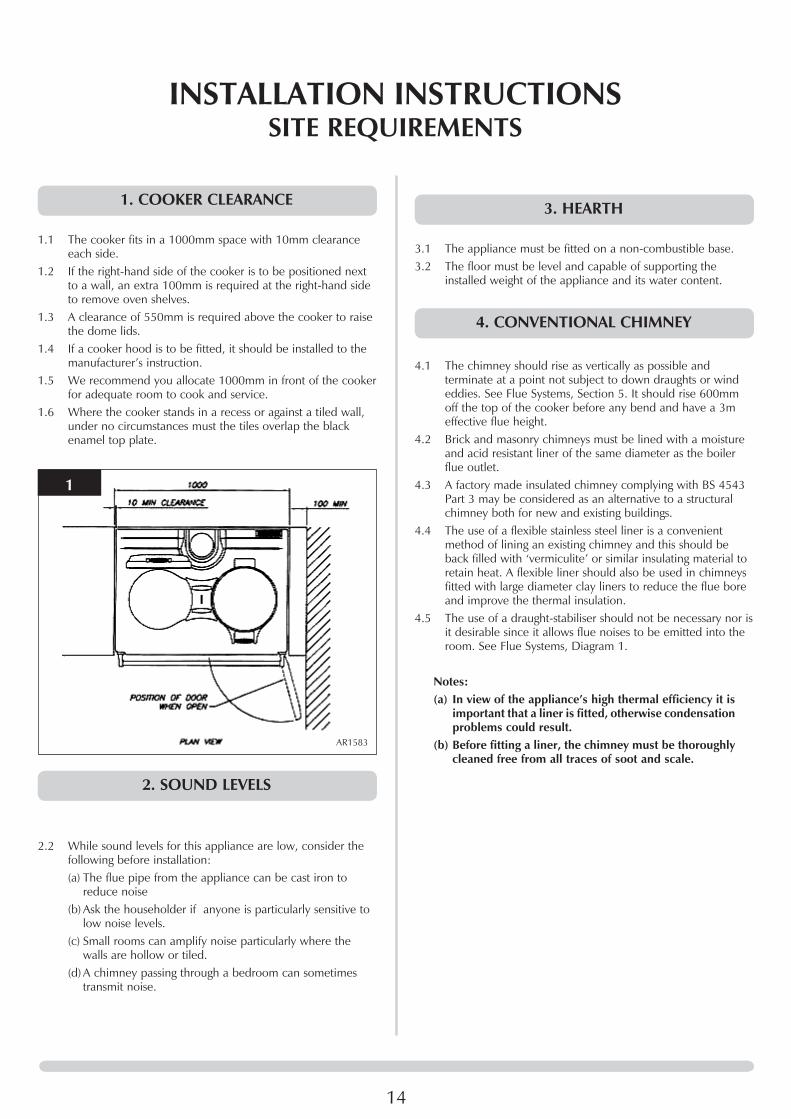
1.1 The cooker fits in a 1000mm space with 10mm clearance each side.
1.2 If the right-hand side of the cooker is to be positioned next to a wall, an extra 100mm is required at the right-hand side to remove oven shelves.
1.3 A clearance of 550mm is required above the cooker to raise the dome lids.
1.4 If a cooker hood is to be fitted, it should be installed to the manufacturer’s instruction.
1.5 We recommend you allocate 1000mm in front of the cooker for adequate room to cook and service.
1.6 Where the cooker stands in a recess or against a tiled wall, under no circumstances must the tiles overlap the black enamel top plate.
1
AR1583
2. SOUND LEVELS
2.2 While sound levels for this appliance are low, consider the following before installation:(a) The flue pipe from the appliance can be cast iron to
reduce noise(b) Ask the householder if anyone is particularly sensitive to
low noise levels.(c) Small rooms can amplify noise particularly where the
walls are hollow or tiled.(d) A chimney passing through a bedroom can sometimes
transmit noise.
INSTALLATION INSTRUCTIONSSITE REQUIREMENTS
3. HEARTH
3.1 The appliance must be fitted on a non-combustible base.3.2 The floor must be level and capable of supporting the
installed weight of the appliance and its water content.
4. CONVENTIONAL CHIMNEY
4.1 The chimney should rise as vertically as possible and terminate at a point not subject to down draughts or wind eddies. See Flue Systems, Section 5. It should rise 600mm off the top of the cooker before any bend and have a 3m effective flue height.
4.2 Brick and masonry chimneys must be lined with a moisture and acid resistant liner of the same diameter as the boiler flue outlet.
4.3 A factory made insulated chimney complying with BS 4543 Part 3 may be considered as an alternative to a structural chimney both for new and existing buildings.
4.4 The use of a flexible stainless steel liner is a convenient method of lining an existing chimney and this should be back filled with ‘vermiculite’ or similar insulating material to retain heat. A flexible liner should also be used in chimneys fitted with large diameter clay liners to reduce the flue bore and improve the thermal insulation.
4.5 The use of a draught-stabiliser should not be necessary nor is it desirable since it allows flue noises to be emitted into the room. See Flue Systems, Diagram 1.
Notes:(a) In view of the appliance’s high thermal efficiency it is
important that a liner is fitted, otherwise condensation problems could result.
(b) Before fitting a liner, the chimney must be thoroughly cleaned free from all traces of soot and scale.
15
5. OIL SUPPLY
5.1 The burners are factory set to burn 28 sec. Kerosene.
Oil Storage Tanks
5.2 The tank should be large enough to allow for economic deliveries and be located in the most unobtrusive position, having regard to the need for safety, filling, maintenance (if steel tank) and the head of oil required.
5.3 It is highly unlikely that a fire could start from a domestic oil tank, but the tanks needs to be protected from any fire originating in a nearby building. The tank should not be located closer than 1.8 metres from a building, nor closer than 760mm from a site boundary. Where a tank has to be less than 1.8 metres, the building wall must not have any openings other than small ventilation openings. The wall shall have a half hour resistance to an internal fire and extend 1.8 metres from any part of the tank.
5.4 Alternatively, a non-combustible radiation barrier must be provided which meets the requirements of BS 5410 Part 1, 1997. This standard applies to tanks up to a capacity of 3,400 litres which is deemed the maximum size for a single family dwelling.
Steels Tanks
5.5 Steel tanks should comply with the requirements BS799 Part 5: 1987 and mounted on brick or block piers with a waterproof membrane between the piers and the tank.
5.6 The tank should be fitted with fill and vent connections (weather protected), a drain-off cock, shut-off valve and an oil level indicator.
Plastic Tanks
5.7 Polyethylene tanks are now widely used because of their advantages over traditional steel tanks:a) They do no need pier supports and can be mounted
directly on any flat surface giving uniform support for the tank base.
b) They do not corrode and therefore never need painting.c) They are easier to handle because of their lower weight.d) They have a 10 year manufacturer’s guarantee.
5.8 Plastic tanks should be fitted with similar components to those used with steel tanks.
INSTALLATION INSTRUCTIONSSITE REQUIREMENTS
6. MAINS ELECTRIC SUPPLY
Note: THIS APPLIANCE MUST BE EARTHED.6.1 All electrical wiring must be carried out by a qualified
electrician in accordance with current I.E.E. Regulations and any Local Regulations that may apply. The 230v - 50Hz electrical supply to the unit and auxiliary controls must be fused by a double pole switch with a contact separation of at least 3mm in both poles and shuttered socket (both complying with the requirements of BS 1363) adjacent to the boiler.
7. WATER SYSTEMS
7.1 The appliance is suitable for fully pumped open vent & sealed systems only and the installation must comply with the requirements of BS 6798 and BS 5449. Fit a drain off cock in the lowest part of the system. Where the boiler is also to be used for providing domestic hot water, a double feed indirect cylinder to BS 1566 Part must be used. Flush out the system to remove any swarf or residues before fitting the circulating pump
Note: Where the boiler is installed on a gravity type system ensure its high efficiency is considered alongside the
gravitational flow. Failure may result in a temperature build-up within the boiler causing noisy operation.
8. COMBUSTION AIR
8.1 Adequate supply of combustion air is essential for the efficient and safe operation of the appliance.
8.2 The air opening should be positioned where it causes the least draught to the house occupants and is not liable to be accidentally blocked.
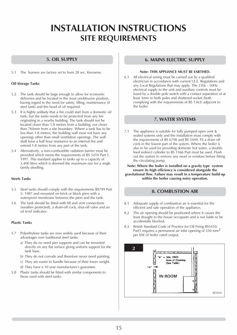
8.3 British Standard Code of Practice for Oil Firing BS5410: Part1 requires a permanent air inlet opening of 550 mm2 per kW of boiler rated output.
2
AR1650

Model Minimum FREE Area opening "A" 60 166 cm2 (15 in2) 80 198 cm2 (19.5 in2) 100 230 cm2 (24.5 in2) 120 262 cm2 (30 in2)
10. ExTRACTOR FAN
10.1 The combustion performance of the appliance must not be affected when the kitchen’s extractor fan is running and all doors and windows are closed. A flue gas check on the CO2 % and smoke number should be carried out.
16
INSTALLATION INSTRUCTIONSSITE REQUIREMENTS

17
1. GENERAL
1.1 This appliance has been designed to conform to European Directive/StandardsBED92/42EECLVDEN60335-1EMC89/336/EEC
1.2 The Redfyre is supplied suitably equipped for connection to a conventional chimney.
1.3 The matched pressure jet burners are exceptionally quiet in operation and ensure clean and efficient combustion with low NOx emissions.
1.4 The central heating boiler has been designed for use on open vent or sealed systems. If it is to be used on a sealed water system up to a maximum working pressure of 3bar, additional safety devices are required.
1.5 A flow and return socket is provided to facilitate connection to the heating/hot water system.
1.6 Because of the high efficiency of this range of boilers, it is recommended they are fitted on a fully pumped system.
1.7 All servicing can be carried out from the front and top of the appliance. This allows the cooker to be fitted between kitchen units. The front mounted flue-cover permits easy access for the removal of the flue baffles and cleaning of heating surfaces.
1.8 The boiler is fully automatic in operation and incorporates all the necessary safety controls to ensure safe and reliable operation.
1.9 The appliance is supplied with the burners set for Kerosene 28 sec. Class C fuel only.
The person(s) who installs this appliance, commissions, services or carries out any remedial work, i.e. electrical fault
finding, must have suitable engineering qualifications.
2. REGULATIONS
2.1 Installation of the appliance must comply with the following British Standards and Regulations:• BS5410LPart1–CodeofPracticeforOilFiring• BS5449–ForceCirculationHotWaterCentralHeating
Systems• TheBuildingRegulations Part ‘J’ (England and Wales) Part ‘F’ Section 111 (Scotland) Part ‘L’ (Northern Ireland)• TheControlofPollution(Oil)Regulations• CurrentI.E.E.Regulations• LocalWaterUndertakingsBy-laws• OFTECInstallationRequirementsforOilFiredBoilersand
Oil Storage Tanks
3. HEALTH & SAFETY AT WORK ACT
3.1 The installer should be aware of his responsibilities under the Act and provide, where necessary, appropriate protection for persons carrying out the installation.
3.2 In the interest of safety, the cooker should be installed and commissioned by a competent engineer, preferably OFTEC trained and registered.
3.3 A useful guide to Safe Working Practices for Oil Firing Technicians is published by OFTEC.
Health & Safety
INFORMATION FOR THE INSTALLER AND SERVICE ENGINEERS3.4 Under the Consumer Protection Act 1987 and the Health &
Safety at Work Act 1974, it is a requirement to provide information on substances hazardous to health (COSHH Regulations 1988).
3.5 The Company takes every reasonable care to ensure these products are designed and constructed to meet these general safety requirements, when properly used and installed.
3.6 To fulfil this requirement, products are comprehensively tested and examined before despatch.
3.7 When working on the appliance, it is the Users/Engineers responsibility to ensure that any necessary personal protective clothing or equipment is worn appropriate to parts that could be considered as being hazardous to health and safety.
3.8 This appliance may contain some of the items below.
INSULATION AND SEALS3.9 Glass Rope, Mineral Wool, Insulation Pads, Ceramic Fibre,
Glass Insulation:• Maybeharmfulifinhaled.• Maybeirritatingtotheskin,eyes,noseorthroat.• Whenhandling,avoidinhalationandcontactwitheyes.
Use (disposable) gloves, face masks and eye protection.• Afterhandling,washhandsandotherexposedparts.• Whendisposing,reducedustwithwatersprayand
ensure parts are securely wrapped.• FullMaterialSafetyDataSheetsareavailablefromGazco
if required.
GLUES, SEALANTS & PAINT3.10 Glues, Sealants and Paints are used in the product and
present no known hazards when used in the manner for which they are intended.
INSTALLATION INSTRUCTIONS
18
KEROSENE & GAS OIL FUELS (MINERAL OILS)3.11.1 The effect of mineral oils on the skin vary according to the
duration of exposure.3.11.2 The lighter fractions also remove the protective grease
normally present on the surface of the skin rendering the skin dry, liable to crack and more prone to damage caused by cuts and abrasions.
•Avoid,asfaraspossible,anyskincontactwithmineraloilor with clothing contaminated with mineral oil.
•Donotfiretheburneroutsidethecookeranddonotbreath in mineral oil vapour.
3.11.3 Barrier cream containing lanolin such as Rosalex Antisolv, is highly recommended together with a strict routine of personal cleaning.
3.11.4 Under no circumstances should mineral oils be taken internally.
INSTALLATION INSTRUCTIONSGENERAL
19
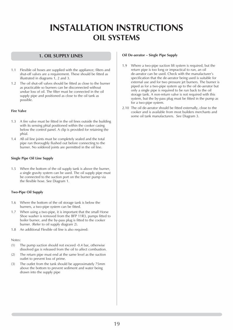
1. OIL SUPPLY LINES
1.1 Flexible oil hoses are supplied with the appliance; filters and shut-off valves are a requirement. These should be fitted as illustrated in diagrams 1, 2 and 3.
1.2 The oil shut-off valves should be fitted as close to the burner as practicable so burners can be disconnected without undue loss of oil. The filter must be connected in the oil supply pipe and positioned as close to the oil tank as possible.
Fire Valve
1.3 A fire valve must be fitted in the oil lines outside the building with its sensing phial positioned within the cooker casing below the control panel. A clip is provided for retaining the phial.
1.4 All oil line joints must be completely sealed and the total pipe run thoroughly flushed out before connecting to the burner. No soldered joints are permitted in the oil line.
Single Pipe Oil Line Supply
1.5 When the bottom of the oil supply tank is above the burner, a single gravity system can be used. The oil supply pipe must be connected to the suction port on the burner pump via the flexible hose. See Diagram 1.
Two-Pipe Oil Supply
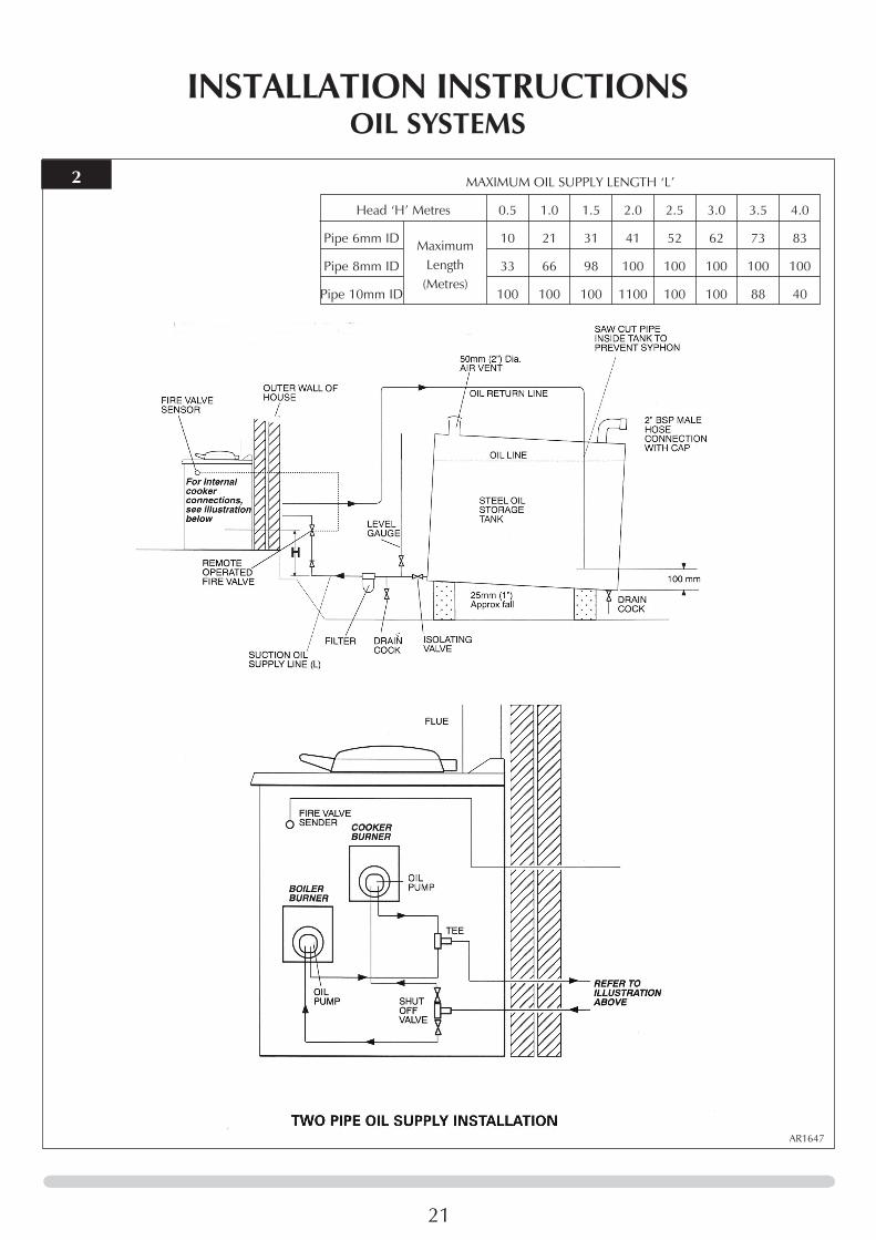
1.6 Where the bottom of the oil storage tank is below the burners, a two-pipe system can be fitted.
1.7 When using a two-pipe, it is important that the small Horse Shoe washer is removed from the BFP 11R3, pumps fitted to boiler burner, and the by-pass plug is fitted to the cooker burner. (Refer to oil supply diagram 2).
1.8 An additional Flexible oil line is also required:
Notes:(1) The pump suction should not exceed -0.4 bar, otherwise
dissolved gas is released from the oil to affect combustion.(2) The return pipe must end at the same level as the suction
outlet to prevent loss of prime.(3) The outlet from the tank should be approximately 75mm
above the bottom to prevent sediment and water being drawn into the supply pipe
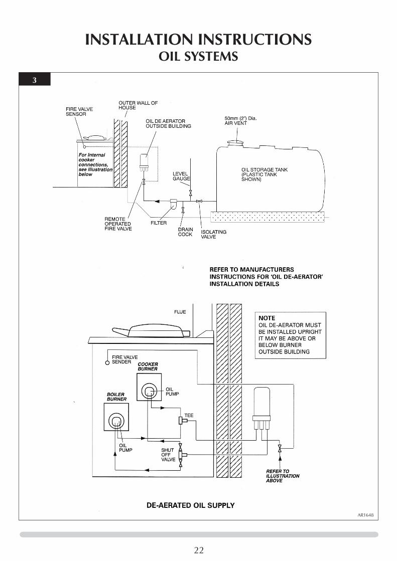
Oil De-aerator – Single Pipe Supply
1.9 Where a two-pipe suction lift system is required, but the return pipe is too long or impractical to run, an oil de-aerator can be used. Check with the manufacturer’s specification that the de-aerator being used is suitable for external use and for two pressure jet burners. The burner is piped as for a two-pipe system up to the oil de-aerator but only a single pipe is required to be run back to the oil storage tank. A non-return valve is not required with this system, but the by-pass plug must be fitted in the pump as for a two-pipe system.
2.10 The oil de-aerator should be fitted externally, close to the cooker and is available from most builders merchants and some oil tank manufacturers. See Diagram 3.
INSTALLATION INSTRUCTIONSOIL SYSTEMS

20
1
AR1649
MAXIMUM OIL SUPPLY LENGTH ‘L’
Head ‘H’ Metres 0.5 1.0 1.5 2.0 2.5 3.0 3.5 4.0
Pipe 6mm ID 10 21 31 41 52 62 73 83
Pipe 8mm ID 33 66 98 100 100 100 100 100
Maximum Length
(Metres)
INSTALLATION INSTRUCTIONSOIL SYSTEMS
21
2
AR1647
MAXIMUM OIL SUPPLY LENGTH ‘L’
Head ‘H’ Metres 0.5 1.0 1.5 2.0 2.5 3.0 3.5 4.0
Pipe 6mm ID 10 21 31 41 52 62 73 83
Pipe 8mm ID 33 66 98 100 100 100 100 100
Pipe 10mm ID 100 100 100 1100 100 100 88 40
Maximum Length
(Metres)
INSTALLATION INSTRUCTIONSOIL SYSTEMS
22
3
AR1648
INSTALLATION INSTRUCTIONSOIL SYSTEMS
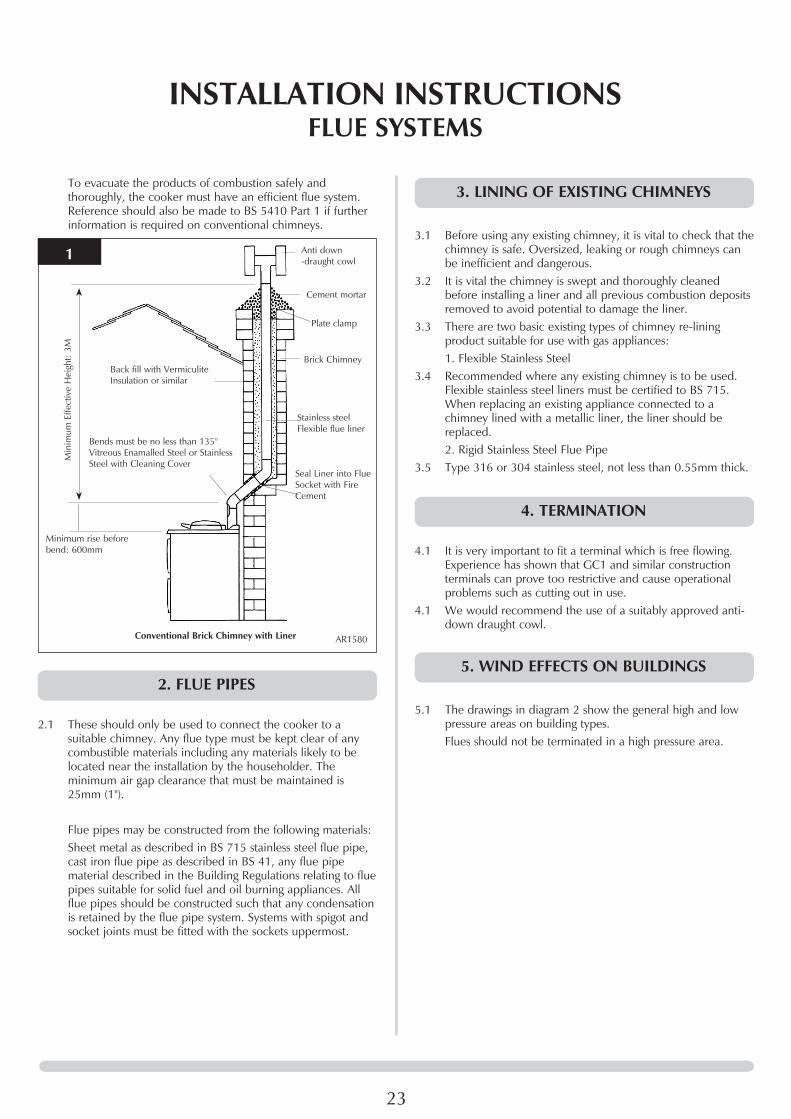
To evacuate the products of combustion safely and thoroughly, the cooker must have an efficient flue system. Reference should also be made to BS 5410 Part 1 if further information is required on conventional chimneys.
1
AR1580
Anti down -draught cowl
BackfillwithVermiculiteInsulation or similar
Bends must be no less than 135° VitreousEnamalledSteelorStainlessSteel with Cleaning Cover
Cement mortar
Plate clamp
Brick Chimney
Stainless steel Flexible flue liner
Seal Liner into Flue Socket with Fire Cement
Min
imum
Effe
ctiv
e H
eigh
t: 3M
Minimum rise before bend: 600mm
Conventional Brick Chimney with Liner
2. FLUE PIPES
2.1 These should only be used to connect the cooker to a suitable chimney. Any flue type must be kept clear of any combustible materials including any materials likely to be located near the installation by the householder. The minimum air gap clearance that must be maintained is 25mm (1'').
Flue pipes may be constructed from the following materials: Sheet metal as described in BS 715 stainless steel flue pipe,
cast iron flue pipe as described in BS 41, any flue pipe material described in the Building Regulations relating to flue pipes suitable for solid fuel and oil burning appliances. All flue pipes should be constructed such that any condensation is retained by the flue pipe system. Systems with spigot and socket joints must be fitted with the sockets uppermost.
23
INSTALLATION INSTRUCTIONSFLUE SYSTEMS
3. LINING OF ExISTING CHIMNEYS
3.1 Before using any existing chimney, it is vital to check that the chimney is safe. Oversized, leaking or rough chimneys can be inefficient and dangerous.
3.2 It is vital the chimney is swept and thoroughly cleaned before installing a liner and all previous combustion deposits removed to avoid potential to damage the liner.
3.3 There are two basic existing types of chimney re-lining product suitable for use with gas appliances:
1. Flexible Stainless Steel3.4 Recommended where any existing chimney is to be used.
Flexible stainless steel liners must be certified to BS 715. When replacing an existing appliance connected to a chimney lined with a metallic liner, the liner should be replaced.
2. Rigid Stainless Steel Flue Pipe3.5 Type 316 or 304 stainless steel, not less than 0.55mm thick.
4. TERMINATION
4.1 It is very important to fit a terminal which is free flowing. Experience has shown that GC1 and similar construction terminals can prove too restrictive and cause operational problems such as cutting out in use.
4.1 We would recommend the use of a suitably approved anti-down draught cowl.
5. WIND EFFECTS ON BUILDINGS
5.1 The drawings in diagram 2 show the general high and low pressure areas on building types.
Flues should not be terminated in a high pressure area.

24
2
AR1645
INSTALLATION INSTRUCTIONSFLUE SYSTEMS

25
INSTALLATION INSTRUCTIONSWATER SYSTEMS
1. GENERAL
1.1 The appliance is suitable for fully pumped open vent & sealed systems only and the installation must comply with the requirements of BS 6798 and BS 5449. Fit a drain off cock in the lowest part of the system. Where the boiler is also to be used for providing domestic hot water, a double feed indirect cylinder to BS 1566 Part must be used.
1.2 An adjustable bypass valve must be fitted between the flow and return and it must be adjusted so that the return temperature to the boiler is always above 60°C. After setting this, the bypass should then be fixed. This increases the life of the heat exchanger and failure to fit a correctly adjusted bypass can invalidate the warranty.
1.3 Flush out the system to remove any swarf or residues before fitting the circulating pump.
2. SYSTEM CONTROLS
2.1 Operation of the system under control of the boiler thermostat alone does not produce the optimum efficiency. The heating system should include a control system. This should have at least a single channel programmer or thermostaticradiatorvalves(TRV).Inthecaseoftheboilerbeing used for central heating and domestic hot water, a 2- channel programmer should be used.
3. SEALED SYSTEMS
3.1 The appliance is suitable for connection to a sealed system and the installer needs to fit an expansion vessel of the correct size, pressure relief valve, pressure gauge, pump and automatic air vents and provide for filling. See diagram 1 for schematic piping diagram.
1
AR1651
4. ExPANSION VESSEL REQUIREMENTS
Bar 0.5 1 1.5 VesselCharge&Initial psi 7.31 4.5 21.8System Pressure
To calculate the expansion vessel required, multiply the total system volume (including 38L for boiler) by the following factor 0.08 0.11 0.16
Note: If the system pressure gauge indicates 2.6 bar or higher with the appliance at maximum temperature and
all radiators in circulation, an additional vessel is required.
Total water content of boiler is 38 litres.
5. SYSTEM FILLING
5.1 A sealed system must only be filled by a competent person using one of the approved methods shown in diagram 2. The system should incorporate the connections appropriate to one of these methods. It is recommended that a suitable inhibitor is added to the system after the final hot flushing.
Method of Makeup:
5.2 Water loss from the system should be replaced from a makeup vessel connected to the system through a non return valve on the return side of the heating circuit. This vessel should be higher than the top of the system.
2
AR1652
5.3 Alternatively provision can be made by pre-pressurisation of the system via a temporary hose connection and through a double check valve (non-return) and stop valve.

26
INSTALLATION INSTRUCTIONSOPEN SYSTEMS
3
AR1629
PLUMBING ‘Y’ PLAN
4
AR1630
PLUMBING ‘S’ PLAN

27
1. ELECTRICITY SUPPLY
Note: THIS APPLIANCE MUST BE EARTHED
1.1 All electrical wiring must be carried out by a qualified electrician in accordance with current I.E.E. Regulations and any Local Regulations that may apply. The 230v - 50Hz electrical supply to the unit and auxiliary controls must be fused by a double pole switch with a contact separation of at least 3mm in both poles and shuttered socket (both complying with the requirements of BS 1363) adjacent to the boiler. Fuse supply at 3 amp. The minimum requirement forthepowersupplycableshouldbeaPVCsheathedflexible cord, at least 0.75mm 2 (24x0.2mm) (code designationH05VV-ForH05VVH2-F)asspecifiedintable16 of BS 6500. The appliance MUST be earthed and the electrical supply earth cable must be of a greater length than the current carrying conductor cables (i.e. live and neutral supply cables). All external cables entering the appliance must be secured in position by strain relief bushes supplied (see diagram on how to secure cable below). Terminal connections are also provided in the control panel for ancillary controls. See wiring diagram 2.
1
AR1631
INSTALLATION INSTRUCTIONSELECTRICAL SYSTEMS
2
AR1644

28
INSTALLATION INSTRUCTIONSELECTRICAL SYSTEMS
3
AR1656
INTE
RNAL
WIR
ING
OF
CO
OKE
R

29
1.1 Independent control or space and water heating circulation in a fully pumped system with two motorised valves (see System Diagrams below).
1.2 This scheme provides the optimum degree of control over a fully pumped installation. Separate two-port motorised valves are fitted in the space heating and water heating circuits controlled by room and cylinder thermostats respectively.
1.3 It operates when the room or the cylinder thermostats call for heat, and open the motorised valve controlling their circuit. The auxiliary switch in the valve switches on both pump and boiler. When either thermostat is satisfied, its motors shut and the auxiliary ceases to provide power for the pump and boiler. When thermostats are satisfied, both valves are closed and the pump and boiler cannot run because their auxiliary switches have opened.
INSTALLATION INSTRUCTIONSWIRING ‘S’ PLAN
4

30
1.1 Independent control of space and water heating circulation in a fully pumped system with one motorised diverting valve (See System Diagram below).
1.2 This scheme provides control over a fully pumped installation by means of a single motorised diverting valve. This provides flow to the space heating circuit or to the water heating circuit. The valve also has a mid position to enable circulating water to flow to both circuits simultaneously. Control is via room and cylinder thermostats.
1.3 The method of operation is that when the room thermostat calls for heat, the valve motors over so that the port serving the space heating circuit is opened and the pump and boiler are both switched on. If the cylinder thermostat calls for heat, the valve motors over to open its domestic hot water port only, and again to switch on the pump and boiler. If both thermostats are calling for heat, the valve motors to open both of its ports and to switch on both pump and boiler. When both thermostats are satisfied, the valve motors to the closed position and the pump and boiler are switched off.
INSTALLATION INSTRUCTIONSWIRING ‘Y’ PLAN
5

31
CD10 FORM
IT IS A REQUIREMENT UNDER OFTEC REGULATIONS THAT THE INSTALLATION IS RECORDED ON A
CD10 FORM (A COPY CAN BE FOUND WITH THIS BOOK). ONCE COMPLETED:
-ONECOPYMUSTBEGIVENTOTHEENDUSER- ONE COPY MUST BE SENT TO GAZCO LTD.
FAILURETODOSOMAYINVALIDATETHEGUARANTEE
COMPLETE THIS FORM NOW

32
SERVICING • Checksetting(seetechnicaldetails) • Examineporcelaininsulatorsforsignsofcracksorglazing,
• Replace,ifnecessary • Carefullypulloutthephotocellandcleanglassface • Cleananydepositsfromimpellerandcheckthatitis
securely fixed to the motor shaft • Removeendcapfromoilpumpsecuredby4allenkey
screws • Takeoutfilterandcleanbywashinginkerosene • Checkflexibleoillinesforwearoroilleaksandreplaceif
necessary • Reassembleinreverseorder-DO NOT REFIT BURNER
UNTIL THE BOILER FLUE WAYS HAVE BEEN CLEANED.
1
AR1642
2
AR1643
To maintain the appliances high thermal efficiency and reliable operation, it must be serviced annually which is also a requirement of the appliances guarantee. If the boiler is used to provide central heating and hot water, we recommend that the appliances annual service is carried out just before the start of the heating season.
NOTE: THE PERSON(S) WHO SERVICES OR CARRIES OUT ANY REMEDIAL WORK, i.e. ELECTRICAL FAULT FINDING, MUST BE
OFTEC APPROVED.
IMPORTANT: ISOLATE ELECTRICAL SUPPLY TO THEAPPLIANCE BEFORE CARRYING OUT ANY WORK
1. OIL TANK
• Opentankanddrainoffanyaccumulatedwaterandsludge
2. LINE FILTERS
• Turnoffoilsupplyatthetank • Removeanyfilterbowl • Washfilterelementcleanwithkerosene • Renewifnecessary • Turnonoilsupply
Important - Oil spillages cause smells
3. BURNER REMOVAL
• Ensureoilsupplyisturned‘off’ • Disconnectthemainspowerplug. Both burners are fitted behind the burner access panel • Removebyremovingthe4securingscrews • Disconnectboththecookerandboilerplugs3.1 The burners can now be removed but it is not necessary to
remove the oil lines.3.2 The boiler burner MUST be removed first by removing the 2
securing nuts.3.3 The cooker burner is removed by unscrewing the 2 burner
securing nuts.3.4 To access: • Removethefourscrewsandflatlidonthetopofthe
burner • Loosentheallenkeygrubscrewholdingtheblasttubein
place • Rotatetheblasttubeandremove • Removethenozzleandreplacewithanewoneofthe
correct specification (see technical data details) - DO NOT ATTEMPT TO CLEAN THE OLD NOZZLE
• Cleanignitionelectrodes,

33
SERVICING
4.COOKER BURNER
4.1 To remove blast tube: • Unscrew4fixingscrewsanddisconnectoilpipefrom
pump • Followthesameprocedureforservicingasboilerburner • Reassembleinreverseorder-DO NOT REFIT THE
BURNER UNTIL THE COOKER FLUE WAYS HAVE BEEN CLEANED.
5. BOILER FLUE WAYS
5.1 The boiler access door is behind the programmer mounting panel.
• Carefullyremovetheprogrammermountingpanelsecured with fixing screws and disconnect the electrical plug
• Removetheboileraccessdoorbyunscrewingthe4nuts • Checksealandrenewifnecessary • Removethebafflesinorder-notingtheorientationas
shown in Baffle Arrangements under the next section: Boiler Heat Exchanger
• Brushandremovealldepositsfromtheinnersurfaceofthe heat exchanger and clean baffles if necessary
• Removefluedepositsfromthechamberusingavacuumcleaner
• Replacebafflesinthecorrectorder
BOILER HEAT ExCHANGER
The following Diagram shows how the baffles look once inside the cooker:
1
AR1573
5.2 First Metal Baffle Diagram 2 shows the first metal baffle being inserted at the
correct angle to start the build.
NOTE: You must tilt the baffle to insert it, keeping the metal legs towards the floor of the cooker.
The end of the baffle with two legs is inserted into the cooker first.
2
AR1574
5.3 First Ceramic Baffle The ceramic baffle is inserted on top of the first metal baffle.
NOTE: The ceramic block must fit onto the lugs of the first metal baffle and sit flat.
3
AR1575
5.4 Second Metal Baffle
Insert the second metal baffle on top of the ceramic baffle with lugs uppermost.
NOTE: Ensure the uneven edge of the metal baffle
is towards the front. See photo.

34
6
AR1578
NOTE: The uneven edge of this metal baffle is now positioned towards the rear of the cooker. See Diagram.
5.7 The following shows the completed baffle assembly:
7
AR1579
• Completethere-assemblybyreferringtotheoriginalinstructions
• Replaceboileraccessdoorensuringthatthesealmakesagas tight seal.
DO NOT FIT THE BOILER BURNER UNTIL THE COOKER BURNER HAS BEEN FITTED
SERVICING
4
AR1576
5.5 Second Ceramic Baffle
• Insertthesecondceramicbaffleontopofthemetalbaffle
5
AR1577
NOTE: The ceramic block engages onto the front and rear lugs of the baffle below. See Diagram.
5.6 Final Metal Baffle
• Insertthelastmetalbaffleontopofthesecondceramicbaffle to complete the assembly

35
Top Plate
• Loosen the M8 nuts under the front left and right edge of the cooker
• Remove the chrome caps from the left and right rear fixings:
12
• Unscrew these two rear fixings • Remove the top plate washer at centre back of cooker:
13
• Lift the top plate clear of the cooker
Without the hotplate and top plate the flue way and combustion chambers can be accessed for inspection and cleaning.
SERVICING
6. COOKER FLUE WAYS
Removal and Replacement of Top for Servicing
To service the combustion chamber or reach the access panel to the flue ways, you need to carefully:
• Remove the cast iron hot plate • Remove the enamel top plate
10
Hotplate • Use an Allen key to unscrew the 4 countersunk screws • Remove the two dummy screws that fix handles at each
end of the hotplate • Fit carrying handles to the hotplate and lift the plate clear
of the cooker:
11
WARNING: THE HOTPLATE IS VERY HEAVY AND IT MAY TAKE TWO PEOPLE TO LIFT OUT – CARE MUST BE TAKEN NOT TO DAMAGE THE BLACK VITREOUS ENAMEL SURROUND.

36
SERVICING
Inspection of Flue Ways
14
At the back left and right of the cooker there are two service hatches
• Unscrew the M5 nuts on the access panel • Carefully remove each washer • Replace gasket if necessary • Inspect and clean the interior chamber
Inspection of Combustion Chamber
15
•Removeboltbyliftingitout •Slidecover •Inspectandcleantheinteriorchamber
Re-assembling the Top Plate after Servicing
IT IS IMPORTANT TO PUT A SPACER BETWEEN THE COOKER TOP PLATE AND THE FOLDED CENTRE WASHER AT THE CENTRE REAR OF THE COOKER TOP WHEN SERVICING OR REPLACING PARTS.
•Refittheaccesspanelcoversoverbothfluewayservicehatches ensuring the washers are used
•Refitthecoveroverthecombustionchamber •Restoretheinsulationontherightandleftsideoftherear
manifold
16
•Restthespaceroverthefixingholeforthecentrewasher.[It can be difficult to do this once the top plate is in place]
17
•Liftthetopplatebackontothecooker •Catchthethreadsontherightandleftfearfixings •Fitthecentrewasherwithgasket MAKE SURE THE FIBRE WASHER SITS UNDER THE
FOLDED CENTRE WASHER AT THIS POINT.
•Catchthethreadonthetorxboltfixing •TightentheM8nutsandgrubscrewsonthefrontof
the top plate ensuring washers are correctly seated •Tightentherightandleftrearfixingsdownandreplace
the chrome caps •Nipuptorxstylefixings

37
Refitting the Hot Plate
WARNING:THEHOTPLATEISVERYHEAVYANDITMAYTAKE TWO PEOPLE TO LIFT OUT – CARE MUST BE TAKENNOTTODAMAGETHEBLACKVITREOUSENAMELSURROUND.
•Usethecarryinghandlestomovethehotplatebackintoposition
•Refitthefourfixingsintothecastironhotplateandthrough the lugs of the top plate beneath
•UseSilverGooptolubricatethesefourfixings •Refitthedummyscrewswherehandlesfix The hotplate should be slightly proud of the top plate: •Restatwo-pencepieceontheenamelsurface.The
hotplate surface should be level with the surface of the two-pence piece.
•Ensurethatagastightsealisachievedaroundthehotplate. Tighten as necessary.
7. RE-ASSEMBLY
When the appliance is thoroughly cleaned and free from any obstruction -
IT IS VERY IMPORTANT THAT ALL SEALS/GASKETS ARE IN GOOD CONDITION, IF NOT REPLACE
Refit all parts in reverse order, again ensuring all access panels are sealed correctly, including the flue way top plates, hotplate and oven access plate.
FAILURE TO DO SO WILL ENABLE FLUE GASES TO ENTER THE ROOM
• Rememberwhenfittingthetopplateandhotplatethatthey are VERY HEAVY AND IT MAY TAKE TWO PEOPLE TO LIFT. CARE MUST BE TAKEN AS DAMAGE TO THE BLACK VITREOUS ENAMEL COULD OCCUR.
• Refitbothburners(cookerburnerfirst,includingairhoseensuring blast tubes are free from deposits.
• Turnonoilandelectricitysupplies. • Checkthecombustionofbothburnersandadjustif
necessary, referring to burner data.

38
1. COOKER
8
AR1638
NOTE: To prime the pump first of all remove the pressure gauge bleed port plug until oil is seen to be present. Replace the pressure gauge/bleed port plug. If the burner goes to lock out after the pre purging time due to lack of pressure in the oil pump, restart the burner
ONE-PIPE SYSTEMS - BFP 21 R3 pumps are supplied for one pipe systems.
TWO-PIPE SYSTEMS - When fitting a two pipe system, the by-pass plug must be fitted, see diagram.
2. BOILER
9
AR1639
NOTE: To prime the pump, first of all remove the pressure gauge bleed port plug until oil is seen to be present. Replace the pressure gauge/bleed port plug. If the burner goes to lock out after the pre-purging time due to lack of pressure in the oil pump, restart the burner.
One Pipe Systems
BFP 11 R3 Pumps are fitted with a small ‘horse shoe’ washer behind the third fixing screw. This allows oil to circulate around the pump on one pipe installations.
Two Pipe Systems
When fitting a two pipe system, the small horse shoe washer must be removed.1. REMOVETHIRDFIXINGSCREW2. REMOVESMALLHORSESHOEWASHER3. REPLACE THIRD FIXING SCREW AND TIGHTEN
DOWN.
SERVICINGPRIMING AND ADjUSTING OF THE PUMP

39
TEST POINT LOCATIONS ON CENTRAL HEATING COOKERS
Boiler
• Removethecontrolpanelhousingtheelectronicprogrammer
• Removetestpointwhichisontheright-handsideofthepanel
Cooker
On right-hand side of the main hotplate:• Removethecentrestud(normallythefixtureforthelifting
handles) DONOTREMOVETHE4STUDSTHATSECURETHE
MAIN HOT PLATE OR STUD AT THE LEFT CENTRE OF THE PLATE
Boiler 60, 80, 100 & 120
The air regulator may have to be adjusted to obtain the correct combustion figures.
MODELS MINOR 1 MINOR 1 MINOR 4 MINOR 8 MINOR1
60/80 80 100 120 COOKERVoltagesinglephase50Hz(V) 230 230 230 230 230
Motor (W) 70 70 90 90 70Rpm (No) 2800 2800 2800 2800 2800Capacitor (uF) 3 3 3 3 3.5Ignitiontransformer(kV/mA) 8.20 8/20 8/20 8/20 8/20Control Box (SATRONIC) TF830.3 TF830.3 TF830.3 TF.803.3 TF803.3Fuel: Kerosene (M.kg)
SERVICINGTECHNICAL DATA
NOZZLE OUTPUTMODELS
Nozzle Spray Spray Pump CO2(%) Usgal/h Angle Pattern Pressure Minor 1 Cooker 0.55 (C.E.N.) 60° Danfoss EH 6.8 bar (100 p.s.i.) 11Minor 1 60 0.60 (C.E.N.) 80° Danfoss EH 6.8 bar (100 p.s.i.) 11Minor 4 80 0.75 (C.E.N.) 80° Danfoss EH 7.5 bar (110 p.s.i.) 11.5Minor 4 100 0.85 (C.E.N.) 80° Danfoss EH 9.5 bar (140 p.s.i.) 12Minor 8 120 1.1 (C.E.N.) 80° Danfoss EH 7.8 bar (115 p.s.i.) 12
10
AR1640
11
AR1641

40
1. BLAST TUBE ASSEMBLY 2. COMBUSTION HEAD SETTINGS
13
AR1636
3. NOZZLE REPLACEMENT
14
AR1637
• Switchoffelectricalsupplytoboilerandturnoffoil• Removeburnerplugfromcontrolbox The burner can now be removed from the boiler• Removetheblasttubefromtheburnerexposingnozzle
holder assembly The nozzle can now be carefully removed taking care not to
damage the electrodes.• Fitanewnozzleofthesamespecification• Checkthepositionoftheelectrodesafterreplacingthe
nozzle to ensure they have not moved.• Refittheblasttubetotheburner
SERVICING
12
AR1635c
AR1635a
AR1635b

41
SERVICINGGUIDE TO FAULT FINDING
BOIL
ER N
OT
WO
RKIN
G –
EN
SURE
TH
ERM
OST
AT IS
SW
ITC
HED
ON
ISTHERE230VONTERMINALS3
OF
MAI
NS
INLE
T PL
UG
?
IS T
HE
BURN
ER L
OC
K O
UT
LIG
HT
LIT?
REFE
R TO
BU
RNER
FAU
LT
FIN
DIN
G S
ECTI
ON
No
Yes
CH
ECK
FUSE
/EXT
ERN
AL
HEA
TIN
G C
ON
NEC
TIO
NS
No
ISTHERE230VONTERMINAL2
OF
BOIL
ER S
TAT
(RED
WIR
E)?
Yes
CH
ECK
FUN
CTI
ON
OF
BOIL
ER
THER
MO
STAT
No
ISTHERE230VONTERMINAL
ON
BO
ILER
LIM
IT W
ITH
RED
AN
D P
URP
LE W
IRE?
Yes
CH
ECK
FUN
CTI
ON
OF
BOIL
ER L
IMIT
TH
ERM
OST
AT (C
HEC
K FU
NC
TIO
N
OFOVERHEATINDICATORLIGHT)
No
CH
ECK
CO
NN
ECTI
ON
OF
PLU
GS
TO B
URN
ER C
ON
TRO
L BO
X
Yes
COOKERNOTWORKING–SWITCHONATCLOCK+THERMOSTAT
ISTHERE230VONTERMINAL
OF
MAI
NS
INLE
T PL
UG
?
IS T
HE
CO
OKE
R BU
RNER
LO
CK
OU
T LI
GH
T LI
T?
REFE
R TO
BU
RNER
FA
ULT
FI
ND
ING
SEC
TIO
N
No
Yes
CH
ECK
7 A
MP
FUSE
SU
PPLY
No
ISTHERE230VONTERMINALL
OF
CO
OKE
R PR
OG
RAM
MER
?
Yes
CH
ECK
PLU
G C
ON
NEC
TIO
NS
No
ISTHERE230VONBLACKWIRE
(SWITCHLIVE)FROM
PRO
GRA
MM
ER?
Yes
CH
ECK
PLU
G C
ON
NEC
TIO
N T
O C
ON
TRO
L BO
XES
No
CH
ECK
OPE
RATI
ON
OF
PRO
GRA
MM
ER (N
OTE
PR
OG
RAM
MER
WIL
L G
O T
O
SLEE
P IF
LEF
T W
ITH
PO
WER
OFF
FO
R 14
DA
YS)
No
ISTHERE230VONBLACKWIRE
ON
CO
OKE
R LI
MIT
STA
T?
Yes
CH
ECK
OPE
RATI
ON
OF
CO
OKE
R TH
ERM
OST
AT
No
ISTHERE230VONDOUBLE
BRO
WN
WIR
E O
N C
OO
KER
LIM
IT S
TAT
Yes
CH
ECK
OPE
RATI
ON
OF
LIM
IT
THER
MO
STA
T AN
D N
EON
IN
DIC
ATO
R
No

42
Electricity safety – Before making any electrical check, switch off mains supply to boiler.
FAULT POSSIBLE CAUSE ACTIONBURNER WILL NOT START Control box locked out – Light on Press reset button on front of burner N.B. ONLY TRY TWICE Boiler thermostat or other system Ensure all controls are calling for heat Controls satisfied Fuse blown Fit new 5 amp fuse. If it bows again, check for short circuit in wiring. Check for live supply continuity up If live supply confirmed, change control box to burner Motor or pump seized Check for rotation and replace as necessary.BURNER STARTS BUT FLAME No oil supply Check oil level in tank and fee to burnerIS NOT ESTABLISHED Photo-cell not seeing flame Clean photo-cell and ensure it is fully plugged in. Air trapped in pump Bleed off air through pressure gauge tapping Solenoid valve faulty Check coil for continuity and replace if faulty Nozzle blocked Replace nozzle with one of same specification Electrodes incorrectly set Reset gap and position electrodes as shown in burner diagram Electrode insulator cracked Check and replace if insulator cracked or crazed Ignition transformer and H.T. Check for spark and condition of HT Contacts contacts. Replace as necessary. Low oil pressure Check pump pressure and adjust to correct setting.FLAME ESTABLISHED BUT Oil contaminated with water Run off oil at burner until free ofBURNER LOCKS OUT AFTER water and drain condensation from tankFEW SECONDS Oil filter partially blocked Wash filter clean with kerosene Photo-cell fault Clean photo-cell and ensure it is fully plugged in. Replace if faulty. Oil pressure low Check pump pressure and adjust to correct setting. Low voltage Check with local Electricity Board. Combustion readings incorrect Check combustion under normal running conditions and compare readings with those given under ‘Burner Settings’. Oil level in tank falling below burner Raise tank or fit a 2-pipe system.DELAYED IGNITION – Nozzle partially blocked Replace nozzle
BURNER PULSATES ON Oil pressure too low Check and decommissionSTART UP Flue blocked or damaged Check and rectify Fan slipping on shaft Check and retighten Pump coupling loose or worn Check and replaceBURNER STARTS VIOLENTLY Delayed ignition Check electrode setting and adjust to correct gap Check electrodes for damage Check H.T. leads for damage and positive connection
FAULT FINDING
43
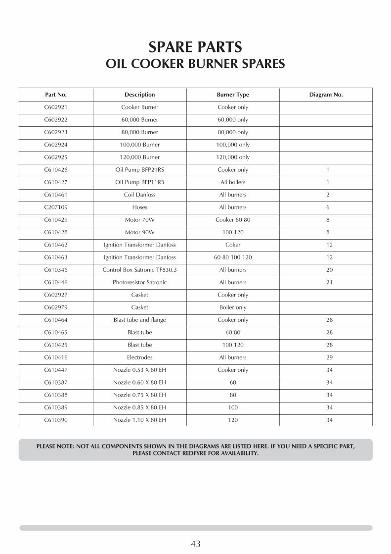
Part No. Description Burner Type Diagram No.
C602921 Cooker Burner Cooker only
C602922 60,000 Burner 60,000 only
C602923 80,000 Burner 80,000 only
C602924 100,000 Burner 100,000 only
C602925 120,000 Burner 120,000 only
C610426 Oil Pump BFP21RS Cooker only 1
C610427 Oil Pump BFP11R3 All boilers 1
C610461 Coil Danfoss All burners 2
C207109 Hoses All burners 6
C610429 Motor 70W Cooker 60 80 8
C610428 Motor 90W 100 120 8
C610462 Ignition Transformer Danfoss Coker 12
C610463 Ignition Transformer Danfoss 60 80 100 120 12
C610346 Control Box Satronic TF830.3 All burners 20
C610446 Photoresistor Satronic All burners 21
C602927 Gasket Cooker only
C602979 Gasket Boiler only
C610464 Blast tube and flange Cooker only 28
C610465 Blast tube 60 80 28
C610425 Blast tube 100 120 28
C610416 Electrodes All burners 29
C610447 Nozzle 0.53 X 60 EH Cooker only 34
C610387 Nozzle 0.60 X 80 EH 60 34
C610388 Nozzle 0.75 X 80 EH 80 34
C610389 Nozzle 0.85 X 80 EH 100 34
C610390 Nozzle 1.10 X 80 EH 120 34
PLEASE NOTE: NOT ALL COMPONENTS SHOWN IN THE DIAGRAMS ARE LISTED HERE. IF YOU NEED A SPECIFIC PART, PLEASE CONTACT REDFYRE FOR AVAILABILITY.
SPARE PARTSOIL COOKER BURNER SPARES

44
Item Description
C602209 Programmer
C602685 Boiler thermostat
C602686 Boiler limit thermostat
C602687 Over-run thermostat
C610467 Combustion chamber r/h side brick
C610467 Combustion chamber l/h side brick
C610467 Combustion chamber front and rear brick
C602844 Flue cover sealing strip (boiler)
C602845 Flue cover insulation (boiler)
C602905 Cooker limit thermostat
C602906 Cooker thermostat
C602935 Flue box gasket (flue manifold)
C602938 Flue service box cover (flue manifold)
C602992 Air hose (fits to burner air intake)
C610254 Top plate spacer (rear centre burner)
C610398 Lower baffle - oil
C610400 Top baffle - oil
C610403 Baffle insulation
SPARE PARTSCOOKER SPARES - (OIL)

45

46

47

Redfyre Limited, Osprey Road, Sowton Industrial Estate, Exeter, Devon, England Ex2 7jGTel: (01392) 444070 Fax: (01392) 444804 E-mail: [email protected]
A Division of Gazco Limited


