Cellulose-derived conductive nanofibrous materials for...
70
THESIS FOR THE DEGREE OF DOCTOR OF PHILOSOPHY Cellulose-derived conductive nanofibrous materials for energy storage and tissue engineering applications VOLODYMYR KUZMENKO Department of Microtechnology and Nanoscience CHALMERS UNIVERSITY OF TECHNOLOGY Göteborg, Sweden 2017
Transcript of Cellulose-derived conductive nanofibrous materials for...
THESIS FOR THE DEGREE OF DOCTOR OF PHILOSOPHY
Cellulose-derived conductive nanofibrous materials
for energy storage and tissue engineering applications
VOLODYMYR KUZMENKO
Department of Microtechnology and Nanoscience
CHALMERS UNIVERSITY OF TECHNOLOGY
Göteborg, Sweden 2017

Cellulose-derived conductive nanofibrous materials for energy storage and tissue
engineering applications
VOLODYMYR KUZMENKO
ISBN 978-91-7597-558-0
© VOLODYMYR KUZMENKO, 2017
Doktorsavhandlingar vid Chalmers tekniska högskola
Ny series nr 4239
ISSN 0346-718X
Micro and Nanosystems group
Electronics Material and Systems Laboratory
Department of Microtechnology and Nanoscience
Chalmers University of Technology
SE-412 96 Göteborg, Sweden
Telephone + 46 (0) 31 772 1000
Technical report MC2-358
ISSN 1652-0769
Cover: The Dala horse made of different cellulose-derived nanofibrous materials
Printed by Chalmers Reproservice
Göteborg, Sweden 2017

iii
Cellulose-derived conductive nanofibrous materials for energy storage and tissue
engineering applications
VOLODYMYR KUZMENKO
Department of Microtechnology and Nanoscience
Chalmers University of Technology
ABSTRACT
There is no doubt that nanofibrous materials are among the most opportune materials used in advanced
applications nowadays. To supply anticipated high demand for these materials sustainable resources such as
plant derived polymers should be explored. In this thesis, I demonstrate that the most abundant natural polymer
cellulose is an excellent raw material for synthesis of new nanofibrous materials with valuable combination of
properties such as electrical conductivity, porosity and topography. These materials can contribute to the solution
of two rather different but equally important problems faced by modern society: lack of high power energy
storage devices able to keep up with the technical progress and increased rate of neurodegenerative diseases,
which inevitably accompanies an ageing population.
In connection with the first problem, supercapacitors are considered to be devices of choice when high power
energy supply is needed. However, the effectiveness of supercapacitors mostly depends on active materials traditionally made of porous carbons which are used for accumulation of electrostatic charges. At the moment,
the production of carbon materials mostly relies on unsustainable fossil precursors. In the present work, I
describe the fabrication of freestanding functional carbon nanofibrous (CNF) materials derived from cellulose
via consecutive steps of cellulose acetate electrospinning, subsequent deacetylation to cellulose, and
carbonization. I report innovative technologically simple and environmentally friendly method of CNF synthesis
that significantly increases carbon yield (from 13% to 20%) and allows time reduction of the regeneration step.
The obtained CNF materials are mechanically stable, have hydrophobic surface and consist of nitrogen-doped
randomly oriented nanofibrous network.
Moreover, the prospect of effective using of various modified CNF-based materials as electrodes in
supercapacitors is demonstrated. Nitrogen-doped CNF materials have about 2.5 times higher specific capacitance
than non-doped CNF materials due the positive effect of pseudocapacitance. Incorporation of highly conductive
carbon nanotubes (double-walled CNTs, multi-walled CNTs and chemical vapor deposited CNTs) and reduced
graphene oxide into the CNF frameworks further improves electrical conductivity and increases the surface area
of the produced composite materials, which leads to high specific capacitance values (up to 241 F/g), cyclic
stability, and power density of these materials. These results show that cellulose is a relevant precursor for the
synthesis of sustainable and efficient carbonaceous electrodes for supercapacitors. Functionalization methods
used in this study proved to be effective in enhancing the electrochemical performance of carbonized cellulose
materials.
In connection with the second problem, an emerging tissue engineering approach can help to cure
neurodegenerative diseases of elderly population via development of healthy replacement neural tissues or in
vitro models for drug testing. In this thesis, several cellulose-derived nanostructures, such as above-mentioned
CNFs and fibrous electrospun cellulose incorporated with CNTs, are assessed as scaffolds for the growth of
neural tissue. These scaffold materials are characterized with good biocompatibility, optimal nanosized
topography and electrical conductivity to support adhesion, growth and differentiation of SH-SY5Y
neuroblastoma cells. Possibility of using inks from nanofibrillated cellulose for 3D printing allows even more
effective assembly of designed conductive patterns for cell guidance. The results show prolific cell attachment,
proliferation and differentiation of neural cells along the guidelines.
In overall, the positive implementation of the cellulose-derived nanofibrous materials in the above mentioned
applications suggest that the synthesis of sustainable and efficient materials based on renewable resources is a
very prospective approach. Such materials should play a major role in our future effort to satisfy the increasing
demand on functional high-tech products.
Keywords: cellulose, electrospinning, carbonization, carbon nanofibers, carbon composites, energy storage,
supercapacitors, hydrogel inks, 3D printing, tissue engineering, neural cells

iv

v
List of publications
The thesis is based on the work contained in the following papers:
Paper I
V. Kuzmenko, O. Naboka, P. Gatenholm and P. Enoksson, Ammonium chloride promoted
synthesis of carbon nanofibers from electrospun cellulose acetate, Carbon 67 (2014) 694–703.
Paper II
V. Kuzmenko, O. Naboka, H. Staaf, M. Haque, G. Göransson, P. Lundgren, P. Gatenholm
and P. Enoksson, Capacitive effects of nitrogen doping on cellulose-derived carbon
nanofibers, Materials Chemistry and Physics 160 (2015) 59–65.
Paper III
V. Kuzmenko, O. Naboka, M. Haque, H. Staaf, G. Göransson, P. Gatenholm and
P. Enoksson, Sustainable carbon nanofibers/nanotubes composites from cellulose as
electrodes for supercapacitors, Energy 90 (2015) 1490–1496.
Paper IV
V. Kuzmenko, A. M. Saleem, H. Staaf, M. Haque, A. Bhaskar, M. Flygare, K. Svensson,
V. Desmaris and P. Enoksson, Hierarchical cellulose-derived CNF/CNT composites for
electrostatic energy storage, Journal of Micromechanics and Microengineering 26 (2016)
124001–7.
Paper V
V. Kuzmenko, N. Wang, M. Haque, O. Naboka, M. Flygare, K. Svensson, P. Gatenholm,
J. Liu and P. Enoksson, Highly conductive cellulose-derived carbon nanofibers/graphene
composite electrodes for powerful compact supercapacitors, submitted.
Paper VI
V. Kuzmenko, T. Kalogeropoulos, J. Thunberg, S. Johannesson, D. Hägg, P. Enoksson and
P. Gatenholm, Enhanced growth of neural networks on conductive cellulose-derived
nanofibrous scaffolds, Materials Science and Engineering C 58 (2016) 14–23.
Paper VII
K. M. O. Håkansson, I. C. Henriksson, C. de la Peña Vázquez, V. Kuzmenko, K. Markstedt,
P. Enoksson and P. Gatenholm, Solidification of 3D printed nanofibril hydrogels into
functional 3D cellulose structures, Advanced Materials Technologies (2016) 1600096.
Paper VIII
V. Kuzmenko, E. Karabulut, E. Pernevik, P. Enoksson and P. Gatenholm, Tailor-made
conductive inks from cellulose nanofibers for 3D printing of neural guidelines for study of
neurodegenerative disorders, submitted.

vi
Other publications by the Author not included in the thesis:
V. Kuzmenko, S. Sämfors, D. Hägg and P. Gatenholm, Universal method for protein
bioconjugation with nanocellulose scaffolds for increased cell adhesion, Materials Science
and Engineering C 33 (2013) 4599–4607.
M. Innala, I. Riebe, V. Kuzmenko, J. Sundberg, P. Gatenholm, E. Hanse and S. Johannesson,
3D Culturing and diff erentiation of SH-SY5Y neuroblastoma cells on bacterial nanocellulose
scaffolds, Artificial Cells, Nanomedicine, and Biotechnology 42 (2014) 302–308.
V. Kuzmenko, D. Hägg, G. Toriz and P. Gatenholm, In situ forming spruce xylan-based
hydrogel for cell immobilization, Carbohydrate Polymers 102 (2014) 862–868.
J. Thunberg, T. Kalogeropoulos, V. Kuzmenko, D. Hägg, S. Johannesson, G. Westman and P.
Gatenholm, In situ synthesis of conductive polypyrrole on electrospun cellulose nanofibers:
scaffold for neural tissue engineering, Cellulose 22 (2015) 1459–1467.
V. Kuzmenko, A. Bhaskar, H. Staaf, P. Lundgren and P. Enoksson, Sustainable
supercapacitor components from cellulose, 11th IEEE International Conference on
Automation Science and Engineering, CASE 2015, Gothenburg, Sweden, 24-28 August 2015.
V. Kuzmenko, A. M. Saleem, A. Bhaskar, H. Staaf, V. Desmaris and P. Enoksson,
Hierarchical cellulose-derived carbon nanocomposites for electrostatic energy storage,
Journal of Physics: Conference Series 660 (2015) 012062.
N. Wang, S. Pandit, L. Ye, M. Edwards, V. R. S. S. Mokkapati, M. Murugesan,
V. Kuzmenko, C. Zhao, F. Westerlund, I. Mijakovic and J. Liu, Efficient surface modification
of carbon nanotubes for fabricating high performance CNT based hybrid nanostructures,
Carbon 111 (2017) 402–410.
Q. Li, M. Haque, V. Kuzmenko, N. Ramani, P. Lundgren, A. D. Smith, P. Enoksson, Redox
enhanced energy storage in an aqueous high-voltage electrochemical capacitor with a
potassium bromide electrolyte, Journal of Power Sources 348 (2017) 219–228.

vii
Acknowledgements
The Wallenberg Wood Science Center funded by the Knut and Alice Wallenberg
Foundation is greatly acknowledged for its financial support.
I would like to address special thanks to my main supervisor Peter Enoksson and co-
supervisors Paul Gatenholm and Olga Naboka for their precious help. I truly appreciate an
opportunity to work with Professionals and Great People such as you.
Thanks to Henrik and Sofia for creating a productive working atmosphere in our office. It
is much fun to have room neighbors like you.
Thanks to Qi, Mazharul, Agin, Amin, Per, Elof, Markus and other colleagues at MC2 who
make this building such an effective tool for producing valuable things for our society.
Thanks to BBV colleagues for having good and productive time there.
And finally, I want to thank my dear wife Julia and son Oskar for their love, inspiration
and sleepless nights You make me a better person and thus a better scientist…
Göteborg, May 2017
Volodymyr Kuzmenko
“Nothing in the world can take the place of perseverance. Talent will not; nothing is
more common than unsuccessful people with talent. Genius will not; unrewarded genius
is almost legendary. Education will not; the world is full of educated derelicts.
Perseverance and determination alone are omnipotent.”
(Calvin Coolidge)

viii
ix
Table of contents
Abstract .................................................................................................................................... iii
List of publications ................................................................................................................... v
Acknowledgements ................................................................................................................. vii
1. Introduction .......................................................................................................................... 1
1.1. Background ...................................................................................................................... 1
1.1.1. Energy storage .......................................................................................................... 1
1.1.2. Tissue engineering (TE) ............................................................................................ 2
1.2. Scope and outline ............................................................................................................. 4
2. Enhanced synthesis of carbon nanofibers (CNFs) from cellulose .................................... 7
2.1. Electrospinning as a fiber production method ................................................................. 8
2.1.1. Basic principles and parameters ............................................................................... 8
2.1.2. Electrospinning of cellulose and its derivatives ..................................................... 10
2.2. CNF fabrication from spun cellulose ............................................................................. 11
2.2.1. Regeneration of cellulose from cellulose acetate.................................................... 11
2.2.2. Carbonization of cellulose ...................................................................................... 13
2.2.3. Effect of ammonium chloride impregnation on cellulosic precursor ..................... 14
2.2.4. Properties of cellulose-derived CNFs ..................................................................... 18
3. CNF-based electrodes for energy storage ........................................................................ 21
3.1. Functionalized CNF materials ....................................................................................... 21
3.1.1. Nitrogen-doped CNFs (NCNFs) ............................................................................. 21
3.1.2. CNF/CNT composites ............................................................................................. 23
3.1.3. CNF/rGO composite ............................................................................................... 25
3.2. Electrochemical performance of CNF-based electrodes ............................................... 28
4. Conductive scaffolds for neural TE .................................................................................. 37
4.1. 2D fibrous scaffolds ....................................................................................................... 37
4.1.1. Scaffold properties .................................................................................................. 37
4.1.2. Cell development on 2D scaffolds .......................................................................... 40
4.2. 3D printed scaffolds ....................................................................................................... 43

x
4.2.1. Optimization of conductive inks for 3D printing .................................................... 43
4.2.2. Scaffold properties .................................................................................................. 44
4.2.3. Cell development on 3D scaffolds .......................................................................... 46
5. Conclusions ......................................................................................................................... 49
Outlook .................................................................................................................................... 51
References ............................................................................................................................... 53

1
Chapter 1
Introduction
1.1. Background
Advanced technologies have become an essential part of human progress. No doubt, one of
the biggest challenges is the development of novel materials with unique properties for
various applications. In the last decades a great deal of attention has been paid to
nanomaterials that have proved to be very promising. This study is concentrated on two of the
possible applications where valuable properties of conductive nanofibrous materials can be
efficiently utilized: energy storage and tissue engineering.
1.1.1. Energy storage
Modern society consumes huge amounts of energy which entails unprecedented scientific
attention towards the development of efficient methods of energy harvesting, storage and
delivery. The boundaries of energy storage field have been tremendously expanded in order to
satisfy various evolving applications. As a result, supercapacitors, whose working mechanism
is based on electrostatic charge accumulations at interfaces between electrodes and electrolyte
ions (Figure 1.1), occupied their niche as high-power energy storage devices with long cycle
life, low maintenance cost, safe pollution-free operation and capability to function at high
temperatures [1-3]. Distinctive advantages promote an extensive use of supercapacitors in
wearable electronics [4,5], uninterruptible power supplies [6], wireless sensors [7], electric
hybrid vehicles [8,9], and energy harvesters, for instance, wind turbines [10], solar cells or
piezoelectric systems [11]. Over the last century, energy consumption in the world has been
constantly increasing, which has brought up the need for efficient devices that can be used to
store and deliver energy on demand. A major contribution to satisfy this need can be made
through implementation of supercapacitors as safe and long-lasting energy storage devices
[12-14].
Figure 1.1. Schematic illustration of the supercapacitor used in the research.
2
Carbonaceous materials, for instance, activated carbons, carbon aerogels, carbon nanotubes
(CNTs), carbon nanofibers (CNFs) and graphene, are the most suitable materials for
supercapacitor electrodes as they have important characteristics necessary for effective
electrical double layer (EDL) energy storage [15-18]. First of all, carbon materials are
electrically conductive, mechanically stable and chemically inert, which helps them to
withstand sufficient number of charge and discharge cycles without significant deterioration.
In addition, they can in a relatively easy and cheap way obtain a high surface area with
controllable porous morphology accessible to an electrolyte [9,17,19,20].
High demand for carbon materials creates the problem of resource availability, thus
orientation on sustainable/renewable resources is vital for the future of energy storage devices
[21]. Deployment of resources of fossil origin for the production of carbon materials is an
immense drawback in the large scale production of carbons, while biomass-derived
nanocarbons are much more cost-effective and do minimal harm to the environment [22].
This is very important aspect as these resources are, firstly, extremely limited, and secondly,
they cause emission of a large amount of greenhouse gases. The search of innovative carbon
materials should be motivated not only by the outlook of consistent performance, but also by
low cost, easy preparation, and minimal detrimental impact on the environment. From the cost
and sustainability point of view, utilization of renewable resources should be considered as a
future alternative to coal tar pitch and synthetic polymers which are usually used as CNF
precursors [23,24]. For the above mentioned reason, plant cellulose is obviously an attractive
candidate for the synthesis of carbons, being the most abundant biopolymer on Earth [25].
Advantages of this biomass source are especially evident in the countries with valuable forest
industry, i.e. in Nordic countries and Canada. And no doubt, the trend of biomass utilization
has a long-term life ahead of it. It becomes even more relevant after the adoption of the Paris
Agreement which makes the world’s biggest economies finally unite their efforts in order to
slow down detrimental climate changes through substantial reductions of greenhouse gas
emissions [26].
1.1.2. Tissue engineering (TE)
In modern society, recovery from spinal cord injuries (SCI) and neurodegenerative diseases
(NDD), such as Alzheimer's disease (AD) and Parkinson's disease, accounts for one of the
biggest global public health challenges in terms of the number of patients and the healthcare
costs. In 2015 it was estimated that over 46 million people in the world suffer from AD,
which lifts the global costs of care for this disease to nearly $818 billion. Unfortunately, these
numbers are expected to grow up even further due to the absence of a permanent cure, the
remaining poor healthcare systems in many underdeveloped regions and continuously ageing
population in the most developed countries [27].
The common current treatments of neurodegenerative health problems include either
invasive surgery or drugs that solely delay or temporarily ameliorate symptoms, and no
permanent cure has yet been developed [28-30]. TE can serve as a novel approach for
improving the activity of nervous systems impaired by SCI and NDD. The neural tissue
supported by tailor-made scaffolds can be used in different ways such as a replacement for
injured tissue (Figure 1.2), as a mechanism of therapeutics delivery or as a drug screening
model for the study of the degenerative neural disorders in vitro [31,32].

3
Figure 1.2. Schematic illustration of a neural TE concept.
For in vitro studies, the support material needs to be non-cytotoxic and to have appropriate
morphology. In addition, the mechanical characteristics of scaffolds are supposed to be
suitable for neural tissue development and furthermore provide stability of structure
throughout the necessary time. Cells are able to attach to non-cytotoxic scaffolds without any
detrimental impact [33]. Additionally, cell adhesion, migration, proliferation and
differentiation, as well as oxygen diffusion and exchange of nutritive and metabolic
substances, are greatly affected by external topography and internal porosity of a scaffold
which should provide required space for cell development processes [34,35]. Furthermore,
electrical conductivity is an inherent characteristic of carbon materials, which is particularly
important for neural TE applications. Since neurons are capable of using electrochemical
signals for transmitting information, scaffolds with electrical conductivity have a positive
influence on the development of neural tissue. In earlier studies, conductive carbon
nanostructures showed a beneficial impact on the performance of neurons at both the single
cell level and the neuronal network level [36-39].
So far, most scaffolds have been implemented as 2-dimensional (2D) models with cells
layered at the flat surface of scaffolds. It is due to the practical handling of such robust
scaffolds, which allows convenient cell monitoring, sufficient cell survival and exchange of
nutrients. However, cell studies in 2D conditions are very dissimilar with a real brain model,
since an actual brain tissue has a 3-dimensional (3D) structure with interconnected functional
layers. A higher spatial freedom for cells to interact with other cells and matrix at the 3D level
makes the developed tissues rather different compared to the ones grown on flat 2D scaffolds
[40,41].
In 3D printing, the mechanical quality of an ink is usually an issue, as an ink has to be
stable, easily printable and result in a scaffold with high shape fidelity in addition to
compatibility with living cells after printing. Cellulose-based inks seem to be able to satisfy
the above-mentioned requirements even better than more popular synthetic polymers.
Although synthetic polymers can be useful for specific applications, the biopolymers such as
cellulose more accurately mimic genuine extra cellular matrix (ECM) conditions [42].
Biopolymer-based scaffolds have already showed good results in TE applications [43].
Despite this, cellulose has been paid very little attention until now in terms of its use in
engineering of new scaffold materials. Since cellulose is a biocompatible polymer [44,45],
mechanically strong cellulose-based materials are inexpensive and sustainable candidates for

4
nerve regeneration. Moreover, cellulose-based materials are able to enhance the host-implant
integration [46] and increase neural attachment and survival [47]. The possibility to
mechanically disintegrate long cellulosic fibers from wood into so-called nanofibrillated
cellulose (NFC) with a diameter of fibers down to 3-6 nm and a length range of few microns
[48,49], provides even more opportunities for cellulose. At very small concentrations around
2 wt.% NFC forms extensively entangled strong hydrogel networks that have essential
properties for a 3D printing ink such as shear thinning, strong thickening and yield stress [50].
The colloidal stability of NFC-based hydrogels is very high due to the introduction of charged
functional groups to the NFC interface [51], which keeps inks integral for a long time.
Besides, NFC is easily miscible with conductive additives to form highly opportune
composites [52]. In particular, charged NFC can act as excellent aqueous dispersion agents for
CNTs [53,54], which is critical for homogeneous CNT distribution and thus sufficient
electrical conductivity of inks.
1.2. Scope and outline
In this thesis, different cellulosic sources, i.e. electrospun cellulose and NFC, were used to
fabricate conductive nanofibrous scaffolds for the advanced applications.
Previous studies have shown a possibility to obtain suitable low cost carbon materials from
cellulose [13,55,56], however low yield of carbonization prevents using cellulose as a
precursor in large scale production. In Chapter 2 an enhanced sustainable method of high-
yield CNF synthesis from cellulose is described [Paper I].
Cellulose-derived CNFs fabricated with different methods were used for application in
energy storage devices such as supercapacitors. In Chapter 3, methods generating four types
of carbon composites based on such CNFs are demonstrated.
Impregnation with NH4Cl was successfully used for high-yield fabrication of nitrogen
doped CNFs from cellulose. Such N-doped carbonaceous materials are perceived as
sustainable electrodes that show promising capacitive effects by the complementation of two
different principles of energy storage: electrostatic from EDL capacitance and electrochemical
from pseudocapacitance [57]. The pseudocapacitance implies transfer of charges across the
double layer at the electrode surface and can be reached by addition of such n-type dopant as
nitrogen [58]. This phenomenon substantially increases the total amount of accumulated
charge and thus the energy density of the supercapacitor [59] [Paper II].
Besides, several different CNF/CNT composite electrodes are described in the thesis. They
are obtained through either carbonization of the cellulosic precursors functionalized with
double-walled carbon nanotubes (CNF/DWCNT) or multi-walled carbon nanotubes
(CNF/MWCNT) [Paper III] or chemical vapor deposition of CNTs on top of CNFs
(CNF/cvdCNT) [Paper IV]. Though there were earlier attempts to integrate CNTs with CNFs
[55,56], the present research offers new fabrication approaches of CNF/CNT composites,
which leads to improved electrochemical performance of the electrode materials. As a result,
one obtains hierarchical electrode materials with strong fusion between two constituents: a
continuous network made of thick CNFs in diameter range of 50-250 nm and much thinner
CNTs with a diameter range of 1-20 nm. On the one hand, the presence of CNTs, which have
high surface-to-volume ratio and electrical conductivity, is expected to have a positive impact
on electrochemical results of the pristine CNF material [15,60,61]. On the other hand,
freestanding CNF network with well-structured pore interconnectivity, high mechanical and
electrochemical stability can maintain the efficiency of the composite without using an
unfavorable polymeric binder [72,62].
Finally, a composite carbon electrode material consisting of CNFs and reduced graphene
oxide (rGO), which is named CNF/rGO, is presented [Paper V]. It was fabricated via
carbonization of the electrospun fibrous cellulose functionalized with graphene oxide (GO).

5
Water-soluble GO has strong affinity to hydrophilic cellulose due to abundant polar surface
functionalities from both sides [63,64], which results in homogeneous coverage of cellulosic
fibers with GO flakes. This structure remains integral and freestanding after simultaneous
one-step carbonization/reduction of cellulose/GO into CNF/rGO at 800 °C. The presented
approach solved the typical problem of graphene sheet restacking due to the following factors:
1) solid-state high temperature reduction, which prevents agglomeration between graphene
layers [65], and 2) the nanospacer effect of CNFs that stick in between graphene layers. Dense
packing of interpenetrated rGO sheets and CNFs makes this structure suitable for
supercapacitors with high volumetric demands in comparison with vast majority of the
previously reported carbon electrodes [19]. Moreover, due to the capability of CNFs to act as
excellent conductive bridges between rGO sheets, the composite’s electrical conductivity is
one of the highest among the 3D graphene nanomaterials [66]. This exceptional feature leads
to efficient electron transport crucial for high power applications [64].
For application in neural TE described in Chapter 4, the focus is made on the production of
conductive nanofibrous scaffolds that can promote neural cell development. Conductive
scaffolds are aimed to support adhesion, growth and differentiation of neural cells, which
could be used in the development of a future disease screening model or a biomaterial for the
regeneration of neural tissue. 2D scaffolds based on electrospun cellulose as a precursor have
suitable properties to mimic the neural ECM environment including its structural,
topographical and mechanical features [67-69] [Paper VI]. 3D scaffolds consist of 3D printed
conductive guidelines on NFC-based films. To print these guidelines, a NFC/CNT composite
conductive ink was developed [Paper VII]. Further, I describe the influence of guidelines’
beneficial features such as nanotopography and conductivity on the attachment, proliferation
and differentiation of human-derived neuroblastoma cells (SH-SY5Y cell lines) [Paper VIII].
This work can open new prospects for cellulose-based low cost 3D printable inks in
fabricating mass affordable reliable scaffolds desperately needed in the TE field.

6

7
Chapter 2
Enhanced synthesis of carbon nanofibers (CNFs) from
cellulose
Today fibers occupy a big niche in the world market. The majority of them are still produced
from organic sources such as cotton or wool; however the contribution of inorganic fibers
increases continuously. Among the inorganic ones it is worth to put more emphasis on carbon
fibers due to the opportunity of their utilization in different high-performance applications
[70-72]. The reduction of the fiber dimensions to nano-size level leads to even better specific
properties [70]. CNFs are monomolecular carbon fibers with diameters ranging from tens of
nanometers to several hundred nanometers, length range is 100 nm – 1000 µm. Carbon fibers
with “nano” dimensions are very prospective as they have high specific surface area owing to
their small diameters [70,72]. The structure of CNFs is different from CNTs which are
composed of one-atom-thick sheets of carbon (graphene sheets). Though CNF mechanical
and electrical properties are not as good as those of nanotubes, they possess one substantial
advantage – they are relatively easy to synthesize with predetermined properties such as
orientation, diameter, and distribution [73].
Carbon nanofibers have very high tensile strength and Young’s modulus (can reach values
of about 12,000 MPa and 600 GPa respectively) which are approximately 10 times that of
steel. The superb mechanical properties of CNFs make them a good reinforcement agent for
different synthetic materials. In comparison with macroscopic fibers, a lower quantity of
nanofibers is required to attain the same reinforcement result and reduce brittleness; their
large specific surface area promotes relaxation processes in the matrix as well, which
improves the impact strength of the reinforced matrix. More than that, the small diameters of
CNFs provide very limited refraction of light which makes them transparent in matrices [70].
Chemical stability with relatively big surface area of a porous nanofibrous material can be
used in energy conversion and storage. Most of the batteries nowadays use sponge-like
electrodes with high discharge current and capacity, and a porous separator between the
electrodes which can prevent short circuit and allow free exchange of ions. CNFs with well
interconnected pores, high mechanical strength and electrochemical stability can be used as
supercapacitor electrodes that improve reversible capacity (long life-time when cycling) or as
hydrogen-storage materials [7,72].
The large surface area and chemical inertness of CNFs can be applied in catalysis. For
example, nanofibers loaded with metallic nanoparticles (Rh, Pt, Pd) are appropriate catalyst
carriers for hydrogenation reactions. The elimination and recycling of the catalyst after the
reaction is not a problem, nanofibers are very effective in the terms of time and conversion,
and they can serve several times without loss of activity [70].
Membranes made of CNFs can be an efficient tool for filtration providing a rather
insignificant decrease in permeability and a higher capability to trap fine particles compared
to conventional filter fibers. The adsorption of particles is determined by the sieve effect for
large particles and by static electrical attraction for particles smaller than the pores. It is a
suitable method to collect airborne particles in the wide diameter range of 0.5-200 µm [72].
CNFs have also found their way into the medical field. The reason is that the dimensions of
proteins, viruses, and bacteria belong to the nanoscale size range. At the moment, vivid
examples of this phenomenon can be observed in TE. Impalefection, a method of gene
delivery, uses CNFs to attach plasmid DNA containing the gene that is intended for entering
the cell. Then this gene-activated matrix is pressed against cells or tissue causing the

8
subsequent gene expression [74]. The similarity in dimensions of CNFs compared to
crystalline hydroxyapatite found in bone, as well as its high strength to weight ratio, can make
it applicable as an orthopedic/dental implant material [75], while electrically conductivity
allows CNF usage as supporting scaffolds for neural regeneration [38].
Magnificent properties of CNFs give a huge number of opportunities of their future
applications in all spheres of life [76], which is the main reason of the growing demand on
them. Improvements in the production process result in the gradual decrease in cost (from
$330 per kilogram in 1970 to less than $11 at the moment) [77], however their current
production is far from being sustainable. In this Chapter, I demonstrate the enhanced method
of CNF synthesis from cellulose via consecutive steps of cellulose acetate electrospinning,
mild deacetylation (regeneration to cellulose), impregnation with ammonium chloride and
carbonization at 800 °C [Paper I].
2.1. Electrospinning as a fiber production method
Electrospinning is the most flexible and easily controlled process of nanofibers production
nowadays. It has several important advantages compared to other methods (melt-spinning,
dry-spinning, template synthesis, self-assembly, phase separation). First of all, electrospinning
allows obtaining continuous nanofibers with desired properties in a relatively simple and fast
way. Secondly, a large variety of fiber assemblies (nonwoven, aligned, patterned etc.) and
fiber diameters (from 3 nm and up to around 10 µm) is possible to get by simple changes in
the process parameters. Thirdly, the produced fibers have an extremely high surface-to-mass
ratio due to a developed porous structure. Finally, electrospinning gives the opportunity to
fabricate nanofibers from completely different materials such as polymers, metals, ceramics,
or to combine them to form composites [72,78,79].
2.1.1. Basic principles and parameters
The electrospinning process is based on the uniaxial stretching of a viscoelastic solution by
electrostatic forces. Continuous fiber formation takes place as long as the solution keeps on
feeding the electrospinning jet. The whole set-up for electrospinning includes a high voltage
source (up to 30 kV), a solution container with milliliter size capillary (e.g. a syringe with a
flat tip needle), and a conducting collector. The solution is usually fed through a positively
charged spinneret with the help of a pump. When it comes out of the needle tip a high voltage
is required to form a jet shooting towards a collector. Once the electric field reaches a critical
value at which the repulsive electric force overcomes the surface tension of polymer solution,
the polymer solution is ejected from the tip to the collector. Strong electrostatic forces make
the solution jet come out from the needle to form a so-called Taylor cone and subsequently
stretch into thin fibers in the direction of the grounded collector. As a result, while the solvent
evaporates solid fibers are collected to produce a nonwoven fibrous mat [72,78,80-82].
The most important parameters that influence the electrospinning process can be divided
into three main categories: 1) solution properties (including viscosity of solution or
concentration, solution charge density, surface tension, polymer molecular weight, dipole
moment, and dielectric constant); 2) controlled variables (applied voltage, distance from
spinneret tip to collector, flow rate, collector and needle tip design); 3) ambient factors
(temperature, humidity, air velocity). Obviously, it is impossible to isolate the effect of many
of the parameters because they all are interrelated. The best way to obtain uniform, smooth
fibers is to try spinning at varied parameters until perfection is reached [80,83,84]. The effects
of electrospinning parameters on fiber size and morphology are described below.
Solution properties: The polymer concentration is directly proportional to the solution
viscosity, which has the biggest influence on the size and morphology of electrospun fibers.
Previous experience of polymer electrospinning shows that a lower concentration leads to the

9
formation of defects such as beads and droplets since the viscosity is too low to create a
strong thin fiber. As a result, the solution is not sufficiently stretched to the collector, but
rather sprayed onto it [85-88]. It also allows some solvent to get to collector and cause wet
fibers to form junctions and bundles [86]. Increasing the solution viscosity significantly
reduces these defects, producing fibers which are more uniform. However, a too viscous
solution is impossible to electrospin due to clogging of the needle tip (solvent evaporates
faster than jet is initiated) [88,89]. The diameter of the electrospun fiber correlates to the
polymer concentration as well. A higher viscosity of the solution results in thicker fibers
[72,86,90,91]. A higher solution conductivity or charge density generally helps to produce
more uniform fibers with fewer defects [87,89,92,93]. The conductivity can be increased by
addition of a volatile salt, alcohol [94], or a surfactant [95].
Controlled variables: The applied voltage has a significant impact on the fiber fine
structure. First and most important of all, the electric field must be strong enough to overcome
the surface tension in order to induce spinning. On the other hand, spinning at as low voltage
as possible is desirable for the production bead-free fibers. In this case the Taylor cone is
formed at the needle tip followed by smooth stretching of the solution. Higher voltages lead to
a jet originating from the liquid surface within the tip (without the Taylor cone being formed)
resulting in beading. A further increase in the electric field can even split the jet into several
[86,88,89]. The flow rate indicates the speed at which the solution is fed to the needle tip.
Different studies prove that lower flow rates allow obtaining uniform fibers with smaller
diameter [89], while higher flow rates yield beaded fibers due to solvent inability to evaporate
before reaching the collector [94,96]. The distance between the tip and the collector (distance
between two electrodes) should be sufficient to let the fibers dry before reaching their final
destination. The distance also affects the shape and diameter of the obtained fibers. The most
suitable distance has to be found experimentally for each electrospinning setup [72,97]. The
designs of the needle tip and the collector also play important roles in electrospinning. Their
huge diversity nowadays allows getting fibers with absolutely unique structures. For example,
coaxial spinning with a two-capillary spinneret makes it possible to produce hollow fibers
[98], spinnerets with multiple tips can produce fibers with various weight ratios of blended
polymers with a controlled distribution [99]. Metal collectors with conductive surfaces
generally help to form fibers with uniform structure without any shrinking or swelling [100].
Non-conductive collectors cause repulsion between the fibers resulting in lower packing
density [91]. Versatile geometries of collectors bring electrospinning to a new level. Obtained
fibers can have different alignment, wide range of diameters and assemblies [101-103].
Ambient factors: Some previous investigations show that the fiber diameter is inversely
proportional to temperature. It can be explained by a correlation between temperature and the
viscosity of a solution [93]. Increasing the humidity results in the appearance of small circular
pores on the surface of the fibers [104].
In this this research work, for electrospinning of precursors for carbon materials, 1.7 g of
CA (Mn = 30 000, 39.8% acetyl groups) was dissolved in 10 mL of solvent mixture (volume
ratio 2:1) of acetone and dimethylacetamide (DMAc) at room temperature. At such CA
concentration, the viscosity of the solution was optimal for continuous electrospinning
without spraying. CA solution was transferred to a 10 mL disposable syringe and then fed
continuously by a syringe pump at a flow rate of 1 mL/h through a stainless steel needle with
a flat tip. The inner diameter of needle was 0.643 mm. The steel needle was connected to a
high voltage supply with a positively charged electrode. A grounded collector (10×10 cm2
steel mesh covered tightly with aluminum foil) was connected to a negatively charged
electrode (Figure 2.1). Voltage between needle and collector was 25 kV, distance – 25 cm.
Temperature was 20-23 °C, relative humidity was artificially controlled with a humidifier and
kept in the range from 45 to 60%. The amount of electrospun CA solution was around 2 mL
for one sample. For electrospinning of TE scaffolds, few parameters (flow rate, voltage and

10
distance to collector) were slightly modified [Paper VI]. Moreover, in this setup the grounded
collector of fiber mats was a rotating at 25 rpm cylinder with a diameter of 10 cm.
Figure 2.1. Electrospinning setup used in this study.
2.1.2. Electrospinning of cellulose and its derivatives
Cellulose is a naturally occurring polysaccharide that consists of D-glucose monomer units
joined by 1–4 glucosidic bonds, forming an ether linkage by the elimination of water (one
molecule may include up to ten thousand units) (Figure 2.2). Strong stabilization of cellulose
crystalline nanofibrils by intermolecular hydrogen bonding and stacking interactions between
cellulose sheets make cellulose relatively stiff and hard to dissolve [105]. It is not soluble in
the most common solvents, which leads to extremely difficult processing of cellulose.
Solvents that can dissolve cellulose have low volatility and high melting temperature, which
makes it hard to remove them completely from the fibers and requires electrospinning to be
performed at relatively high temperatures [106-110].
Figure 2.2. Chemical structure of cellulose.
On the other hand, its derivatives are much easier to handle (using different modifications)
with spinning processes [111]. Cellulose acetate (CA) is a common ester of cellulose. They
are synthesized by a reaction of cellulose with acetic anhydride or acetic acid in the presence
of sulfuric acid. The degree of substitution (DS) of hydroxyls on acetic groups in cellulose
may vary from 0 to 3, the range of 2-2.5 is predominantly used [112]. DS affects the solubility
of CA and hence determines the options for further processing for different applications. For
example, CA with DS of 2–2.5 is soluble in such solvents as acetone, dioxane or methyl
acetate, while celluloses with higher degree of acetylation are soluble in dichloromethane.
11
Generally, acetylation makes cellulose more soluble in organic solvents, so it makes more
suitable for electrospinning processes [23,113], which was used in this study to obtain fibrous
precursor materials from CA. In order to choose a good solvent several factors should be
taken into consideration. First of all, the solvent must have a high enough boiling point and
dipole moment in order to evaporate during the stretching of the fibers towards the collector
and not before. Otherwise clogging of the needle tip is observed. Secondly, the resulting
solution should not be too viscous, but it should have high conductivity and low surface
tension [114-116]. That is why the presence of solvents with a high dielectric constant and
boiling point like dimethylacetamide, methanol, dimethylformamide or water improves the
spinnability of CA solutions. Usually they are mixed with low-boiling solvents (acetone,
chloroform, dichloromethane) in different weight ratios to obtain the best suitable solvent for
a particular molecular weight of CA and a target structure [84]. After getting cellulose acetate
fibers they are regenerated to cellulose by aqueous or ethanolic hydrolysis [111].
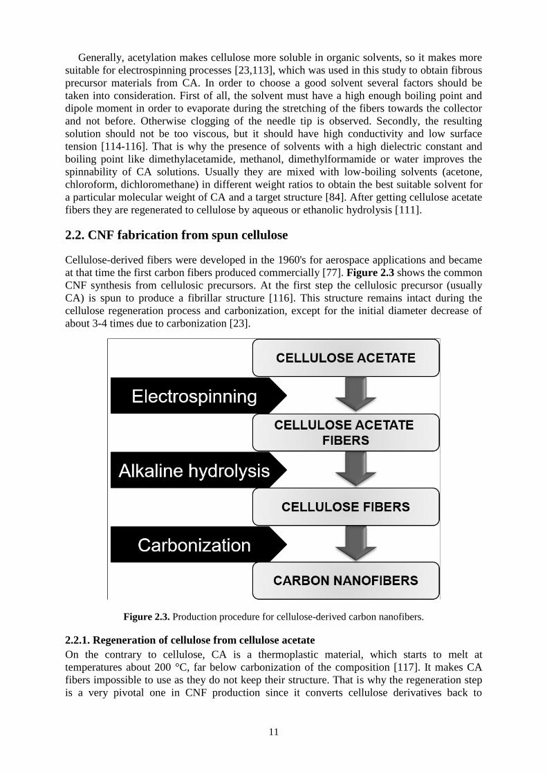
2.2. CNF fabrication from spun cellulose
Cellulose-derived fibers were developed in the 1960's for aerospace applications and became
at that time the first carbon fibers produced commercially [77]. Figure 2.3 shows the common
CNF synthesis from cellulosic precursors. At the first step the cellulosic precursor (usually
CA) is spun to produce a fibrillar structure [116]. This structure remains intact during the
cellulose regeneration process and carbonization, except for the initial diameter decrease of
about 3-4 times due to carbonization [23].
Figure 2.3. Production procedure for cellulose-derived carbon nanofibers.
2.2.1. Regeneration of cellulose from cellulose acetate
On the contrary to cellulose, CA is a thermoplastic material, which starts to melt at
temperatures about 200 °C, far below carbonization of the composition [117]. It makes CA
fibers impossible to use as they do not keep their structure. That is why the regeneration step
is a very pivotal one in CNF production since it converts cellulose derivatives back to

12
cellulose, thus creating a proper precursor for carbonization. The distinctive property of
cellulose to decompose before it melts is the main reason for that [23].
Figure 2.4. Deacetylation of cellulose diacetate with KOH.
The treatment of cellulose esters in alkaline solutions leads to the removal of the
carboxylic groups and the regeneration of the cellulose. The hydrolysis of carboxylic esters
catalyzed by alkali agents in liquid solution takes place via a three-step process as it is shown
in the example of cellulose acetate in Figure 2.4. In the first step, the negative ion RO- (R is
usually hydrogen atom if alkali bases are used) from the base regenerative agent attacks the
ester carbon creating delocalized negative charge between oxygen atoms. This step is
reversible and the slowest one, which means that it determines the overall rate of cellulose
regeneration. The other two steps are fast and irreversible resulting in acetic acid and alcohol
as the products. At the end, the acetate groups of cellulose acetate turn into cellulose-OH by
hydrogen abstraction [113].
Yet there are several disadvantages that make a traditional method of deacetylation with
alkali economically and environmentally unfavorable. Firstly, deacetylation should be
executed at extreme pH levels in order to reach the lowest degree of acetyl substitution.
Moreover substantial amounts of water are required to wash the product from reagents, which
is unacceptable for application in green processes [118]. Ammonium hydroxide as a mild
reagent could be a viable alternative to strong inorganic bases. It does not need time- and
water-consuming washing since it is a volatile compound and is entirely removed during
drying of the carbonization precursor. However, the limiting factor for NH4OH use is the
extensive time required for complete CA hydrolysis (up to a few weeks) [119].

13
2.2.2. Carbonization of cellulose
At the last stage of CNF production, cellulosic precursors are carbonized. In this work, cellulosic samples were placed between two silicon wafers into a quartz tube furnace with
inert N2 flow. Temperature was raised with rate of 5 °C/min up to 800 °C and was held there
for 2 h. After that the furnace was turned off, the samples were left in the oven until the
temperature inside reached room temperature in flowing nitrogen. Carbonization allows
transformation of the organic precursor into a material that contains predominantly carbon.
The precursor has to be heated in a reducing or inert environment. The temperatures may vary
depending on the nature of the particular precursor, sometimes extending to 1300 °C. As the
result, after the complex process that includes different reactions the initial organic precursor
turns into a valuable carbon material, while volatile compounds diffuse out of the system. The
carbon content of this residue differs depending on the nature of the precursor and the
pyrolysis temperature, but usually stays in the range 90 to 99 wt.%. Another important aspect
of carbonization is the carbon yield, which is the ratio between the weights of the carbon
material after and before carbonization. The yield is influenced by the heating rate, the
carbonization atmosphere, and the pressure. Typically, carbon yield does not exceed 60%. In
order to avoid disruption and rupture of the carbon network the diffusion of volatile
compounds should be slow. The duration of carbonization depends on the desired structure of
the product, the type of precursor, and the thickness of the material. At the end of
carbonization “amorphous carbon” is typically obtained. X-ray diffraction shows that it lacks
long-range crystalline order and the deviation of the interatomic distances of the carbon atoms
from the perfect graphite crystal is more than 5% in both the basal plane and between planes
[77]. To obtain a more ordered structure of carbon (graphitizing carbon) carbonization should
be conducted at higher pressures or with the use of a catalyst [120].
Cellulose is a renewable and abundant biopolymer [25] and could be an inexhaustible
source for the synthesis of CNFs. However a cellulosic precursor (C6H10O5)n suffers from low
carbonization yields that do not exceed 10-15% while the initial carbon content in cellulose is
44.4% [121-123]. During pyrolysis and carbonization the cellulosic precursor continuously
releases some compounds. At the first stage absorbed water is lost at temperatures up to about
120 °C, after that a dehydration process occurs up to 300 °C resulting in dehydrocellulose
(Figure 2.5). At about 250 °C simultaneously with dehydration cellulose starts to
depolymerize mostly forming 1,6-anhydro-b-D-glucopyranose (levoglucosan). This chain-
splitting reaction is not desirable since it lowers the yield. At the last stage highly volatile
gases, a tarry distillate and a carbon char are formed [77].

14
Figure 2.5. Changes in chemical structure of cellulose during the first stages of carbonization cycle.
2.2.3. Effect of ammonium chloride impregnation on cellulosic precursor
In order to produce economically viable carbon fibers, a precursor should be easily converted
to carbon at as high yield as possible [124]. One of the approaches that can be used to increase
the carbonization yield and decrease shrinkage is control of a heating rate [125,126]. For
example, holding the temperature at the beginning of carbonization below 250 °C for few
hours can prolong desired dehydration process and postpone excessive chain-splitting
depolymerization [127]. Yet the approach mentioned above is time-consuming and cannot
increase the carbon yield significantly. Impregnation of the cellulosic precursor with various
flame retardants capable of creating covalent crosslinks has proved to be a more efficient
method [128,129]. Unlike some highly corrosive carbonization promoters that require special
equipment [122,129,130] or contaminate carbon with the products of their thermal destruction
[131], ammonium chloride is seen to be very promising additive from the point of view of its
low cost and efficiency. Generally, halogenated flame retardants act during carbonization in a
vapor phase by preventing free-radical chain splitting reactions of cellulose [132], while
ammonium salts stimulate oxidation of C6-atom to an aldehyde group resulting in the
decreased evolution of low-molecular weight compounds in the temperature range of 180-230
°C [133].
The positive influence of ammonium chloride as a flame retardant on the synthesis of
CNFs from cellulose is further discussed in this Section. For cellulose regeneration,
electrospun CA mats were deacetylated/hydrolyzed. For this purpose, they were immersed
into different solutions of sodium hydroxide (NaOH, different concentrations) and ammonium
hydroxide (NH4OH, 28%) in 100 mL plastic beakers as shown in Table 2.1. After this,
samples hydrolyzed in NaOH (CNF005 and CNF01) and pure NH4OH (CNFam) were
washed in deionized water several times until neutral pH was reached. Samples hydrolyzed in

15
NH4OH + NH4Cl (CNFam031, CNFam034) were not washed after the hydrolysis. For drying
procedure, all samples were spread inside PS Petri dishes at a room temperature with lids
slightly open.
Table 2.1. Conditions of cellulose regeneration [Paper I].
Final sample name Regeneration agent Concentration Time (days)
CNF005 NaOH 0.05 m 1
CNF01* NaOH 0.1 M 1
CNFam NH4OH 28 wt.% 4
CNFam031 NH4OH + NH4Cl 28 wt.% + 0.3 M 1
CNFam034 NH4OH + NH4Cl 28 wt.% + 0.3 M 4
*The sample was denoted as “CNF” and used as a reference in the later studies.
Morphology of samples was investigated using scanning electron microscopy (SEM).
Flexible 50-100 μm thick mats, consisting of randomly oriented fibers with 0.5-1.5 μm in
diameter, were fabricated by electrospinning of CA. After the regeneration process cellulose
fibers retained very similar morphology to native electrospun CA fibers (Figure 2.6).
Figure 2.6. SEM images of electrospun CA fibers (a) and cellulosic precursor for CNFam sample
after the regeneration (b).
The Fourier-transform infrared (FTIR) spectroscopy was used to analyze the changes in the
chemical structure after deacetylation (Figure 2.7). The main adsorption bands of the FTIR
spectrum of pure CA are represented by stretching vibrations of C=O from ester groups (1770
cm-1), C–O from carboxylic group (1270, 1085 and 920 cm-1) and acetal linkage of cellulose
backbone (1160 cm-1), O–H group (around 3500 cm-1), as well as by bending vibrations of
CH3 deformation for groups of acetate substituent (1385 cm-1) [134,135]. Spectra of the
cellulosic precursors for the samples CNF005, CNF01 and CNFam were characterized by the
absence of C=O bands and the decrease of C–O and CH3 bands, and significant increase of
the O–H peak at 3500 cm-1. These spectra are comparable with the ones of native cellulose
[136,137], which points to almost complete deacetylation of the mentioned samples. FTIR
spectra of NH4Cl-impregnated cellulose have bands at 1400, 1680, 3040 and 3145 cm-1
caused by stretching vibrations of NH4+, and bands assigned to bending vibrations of the
crystal lattice at 1760 and 2000 cm-1 [138]. The peaks designated for C–O stretching
vibrations still have decreased considerably after the regeneration, while it is hard to judge
about the presence of alkyl CH3 bending because of its overlapping with NH4+ vibrations at
1400 cm-1. The similar effect is observed for C=O stretching vibrations (1770 cm-1) [135]
overlapping with two adjacent stretching and bending modes of NH4Cl (1680 and 1760 cm-1

16
respectively) [138]. The peak at 2000 cm-1 is assigned to bending vibration of the ammonium
chloride crystal lattice, and the broad peaks at 3100-3300 cm-1 are assigned to NH4Cl
stretching band [139, 140].
Even though assignment of FTIR spectra of CA hydrolyzed in the presence of NH4Cl is
complicated, no signs of NH4Cl influence on the cellulose regeneration were observed.
Figure 2.7. FTIR spectra of the regenerated cellulosic precursors in comparison with CA.
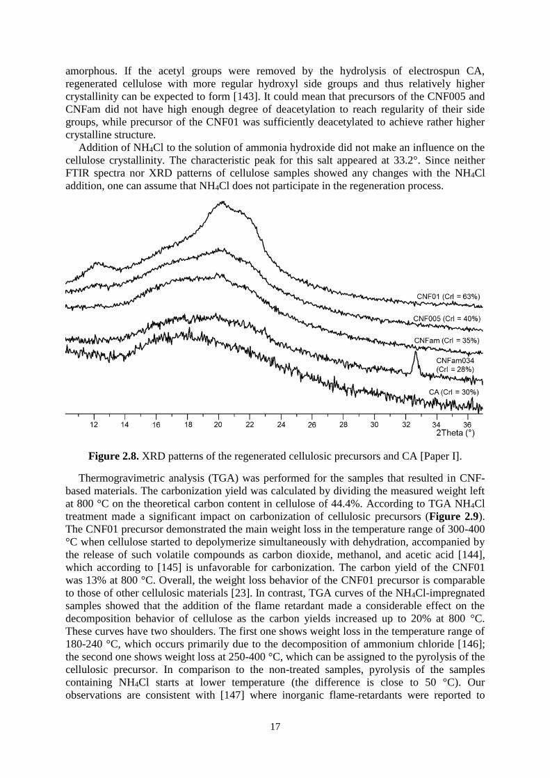
Figure 2.8 shows X-ray diffraction (XRD) patterns of the differently regenerated cellulose
samples. XRD pattern of cellulosic precursor for CNF01 sample regenerated with 0.1 M
NaOH showed presence of peaks around 12°, 20° and 22°, which were assigned to crystalline
structure of cellulose II [141]. Crystallinity index (CrI) of regenerated cellulose was
determined as in Eq. (1) [142]:
CrI = 100(Imax−Imin )
Imax (1)
where Imax is the scattered intensity of the main peak for the regenerated cellulose at
maximum (2θ = 18-22°), and Imin is the scattered intensity at the minimum (2θ = 13-15°).
XRD spectra of rest of the samples showed less defined crystalline peaks similar to the
amorphous electrospun CA. CrI of CNF01 precursor was 63%, while for the other samples it
was in the range of 25-40%. CrI of CA was 30%. Similarity of the XRD patterns of the
CNF005 and CNFam precursors with the XRD pattern of CA could point to incomplete
regeneration of cellulose from electrospun CA (on the contrary to the results of FTIR
spectroscopy). The heterogeneous distribution of the acetyl groups and the hydroxyl groups
along the CA chain leads to a low regularity of the segments, which makes the polymer
17
amorphous. If the acetyl groups were removed by the hydrolysis of electrospun CA,
regenerated cellulose with more regular hydroxyl side groups and thus relatively higher
crystallinity can be expected to form [143]. It could mean that precursors of the CNF005 and
CNFam did not have high enough degree of deacetylation to reach regularity of their side
groups, while precursor of the CNF01 was sufficiently deacetylated to achieve rather higher
crystalline structure.
Addition of NH4Cl to the solution of ammonia hydroxide did not make an influence on the
cellulose crystallinity. The characteristic peak for this salt appeared at 33.2°. Since neither
FTIR spectra nor XRD patterns of cellulose samples showed any changes with the NH4Cl
addition, one can assume that NH4Cl does not participate in the regeneration process.
Figure 2.8. XRD patterns of the regenerated cellulosic precursors and CA [Paper I].
Thermogravimetric analysis (TGA) was performed for the samples that resulted in CNF-
based materials. The carbonization yield was calculated by dividing the measured weight left
at 800 °C on the theoretical carbon content in cellulose of 44.4%. According to TGA NH4Cl
treatment made a significant impact on carbonization of cellulosic precursors (Figure 2.9).
The CNF01 precursor demonstrated the main weight loss in the temperature range of 300-400
°C when cellulose started to depolymerize simultaneously with dehydration, accompanied by
the release of such volatile compounds as carbon dioxide, methanol, and acetic acid [144],
which according to [145] is unfavorable for carbonization. The carbon yield of the CNF01
was 13% at 800 °C. Overall, the weight loss behavior of the CNF01 precursor is comparable
to those of other cellulosic materials [23]. In contrast, TGA curves of the NH4Cl-impregnated
samples showed that the addition of the flame retardant made a considerable effect on the
decomposition behavior of cellulose as the carbon yields increased up to 20% at 800 °C.
These curves have two shoulders. The first one shows weight loss in the temperature range of
180-240 °C, which occurs primarily due to the decomposition of ammonium chloride [146];
the second one shows weight loss at 250-400 °C, which can be assigned to the pyrolysis of the
cellulosic precursor. In comparison to the non-treated samples, pyrolysis of the samples
containing NH4Cl starts at lower temperature (the difference is close to 50 °C). Our
observations are consistent with [147] where inorganic flame-retardants were reported to

18
decrease the threshold decomposition temperature of cellulose. Such a decrease of pyrolysis
temperature can explain the successful carbonization of incompletely regenerated cellulose.
Even though incompletely regenerated cellulose retains thermoplasticity, its melting
temperature increases with a decrease of the degree of substitution. Chen with coworkers
reported melting temperatures for hydrolyzed cellulose acetate to be in the range of 278-313
°C [148]. This temperature range is higher than the temperature of pyrolysis observed in TGA
in our work. Thus, carbonization of cellulosic precursors starts before melting and fibers
retain their morphology. Significant carbon yield increase for ammonium chloride treated
samples is observed because NH4Cl prevented chain splitting reactions of cellulose and
decreased evolution of low-molecular weight compounds [132,133].
Figure 2.9. TGA of the cellulose precursors without (CNF01) and with (CNFam031) NH4Cl
impregnation.
2.2.4. Properties of cellulose-derived CNFs
SEM images of the CNF materials obtained from carbonization of non-impregnated cellulose
are shown in Figure 2.10. Carbonization of CNF01 precursor resulted granular nanofibers
with the diameter of 50-250 nm (Figure 2.10a). The morphology of the produced CNFs
essentially resembled the structure of cellulose precursor shown in Figure 10. The shrinkage
of fibers occurred due to the weight loss. The fibrous structure of cellulose samples
regenerated with NH4OH, as well as the samples regenerated with 0.05 M NaOH vanished
during the carbonization. The fibers almost completely melted together; only at some areas
fibrous patterns may be observed (Figures 2.10b,c). These results point to the thermoplasticity
of CNF005 and CNFam precursors. It is most probably attributed to the presence of acetate
groups caused by the incomplete hydrolysis of the CA [149]. Even though carbonization
results are contradictory to the FTIR spectroscopy data, they are consistent with the XRD data
showing low crystalline order for these precursors.
Figure 2.10. SEM images of the CNFs synthesized from non-impregnated cellulosic precursors: (a)
CNF01, (b) CNF005, (c) CNFam.

19
On the other hand, carbonization of the regenerated cellulose samples impregnated with
NH4Cl led to the formation of fibrous mats with the larger diameter of fibers (70-400 nm)
compared with the samples carbonized in absence of NH4Cl (Figure 2.11). On the contrary to
non-impregnated CNFam sample mentioned above, no fusing of fibers was observed for the
samples CNFam031 and CNFam034, though in both cases NH4OH was used as the main
regeneration agent.
There is also some difference in the morphology between the CNFs synthesized from the
NH4OH-regenerated cellulose samples and the NaOH-regenerated ones. The latter have
relatively smooth surface, while the NH4OH-regenerated samples (CNFam031 and
CNFam034) have rough surface. The similar effect was observed in [150] where NH4+ might
have acted as an activating agent increasing the total surface area.
Figure 2.11. SEM images of the CNFs synthesized from the non-impregnated precursor (a. CNF01) in
comparison with the NH4Cl-impregnated precursor (b. CNFam031 and c. CNFam034).
Taking into account that NH4Cl did not induce changes either in the chemical or in the
crystalline structure of deacetylated samples (according to FTIR and XRD), it is the flame
retardant properties that are most probably responsible for the thermal stabilizing effect of
cellulose. The results presented above could be used as an alternative and greener way of
CNF synthesis which has not only the environmental advantages but also economic benefits
in comparison to the already existing ones. Furthermore, the nitrogen doping achieved via this
method improves CNF performance as an electrode material for application in energy storage
devices, which is analyzed in the Paper II (Section 3.1.1).

20

21
Chapter 3
CNF-based electrodes for energy storage
3.1. Functionalized CNF materials
CNFs are one of the most convenient materials for effective energy storage due to their
mechanical strength, electrochemical stability and high electrical conductivity. However, their
performance can be substantially improved with value-added functionalization. In this study,
few different methods of CNF functionalization were used. First of all, regular electrostatic
principle of energy accumulation on CNF material was complemented with pseudocapacitive
effects reached by nitrogen dopant. Furthermore, addition of CNTs and rGO with high
surface-to-volume ratio and electrical conductivity was aimed at the increase of an active
surface area and general capacitive performance of CNF-based electrodes. For comparable
results, all the electrode materials were fabricated from the same cellulosic precursor (CNF01
precursor). Non-functionalized resulting material was named CNF.
3.1.1. Nitrogen-doped CNFs (NCNFs)
Pseudocapacitive effects from faradaic reactions that involve heteroatoms such as nitrogen
can bring the performance of storage systems to a next level [57]. To incorporate nitrogen
heteroatoms into CNFs, prior to carbonization, regenerated cellulosic samples were immersed
into 0.3 M and 0.5 M solutions of NH4Cl with different concentration (0.3 M and 0.5 M) for
different time (1 and 4 days) to obtain precursors for NCNFs. Afterwards these precursors
were transferred to polystyrene Petri dishes for drying at ambient conditions in air [for details,
see Paper II] and further carbonized. This convenient method of doping provides efficient
incorporation of nitrogen atoms into freestanding carbon nanomaterials via carbonization of
NH4Cl-treated electrospun cellulosic precursors. As a result, capacitive performance of such
carbons is enhanced by doping with an intention to combine two different principles of energy
storage: electrostatic from EDL and electrochemical from pseudocapacitance.
In Figure 3.1 the morphology of the functionalized electrodes is shown. In general, NCNF
material consists of smooth fibers with the diameter of fibers in the range of 70-400 nm,
which is similar to the pure CNFs shown, but there are differences as well. The CNF fibers
have smaller diameter (50-250 nm) and are characterized with the partial fusion of fibers that
can possibly be attributed to residues of non-hydrolyzed acetate groups, which results in the
remaining thermoplastic behavior [149]. In contrast, impregnation with NH4Cl before
carbonization allows obtaining NCNFs with a much more open structure due to less
contraction of the samples. NH4Cl thermally stabilizes incompletely regenerated cellulose
fibers and increases the carbon yield of the CNFs, as was discussed above in Section 2.2.3.
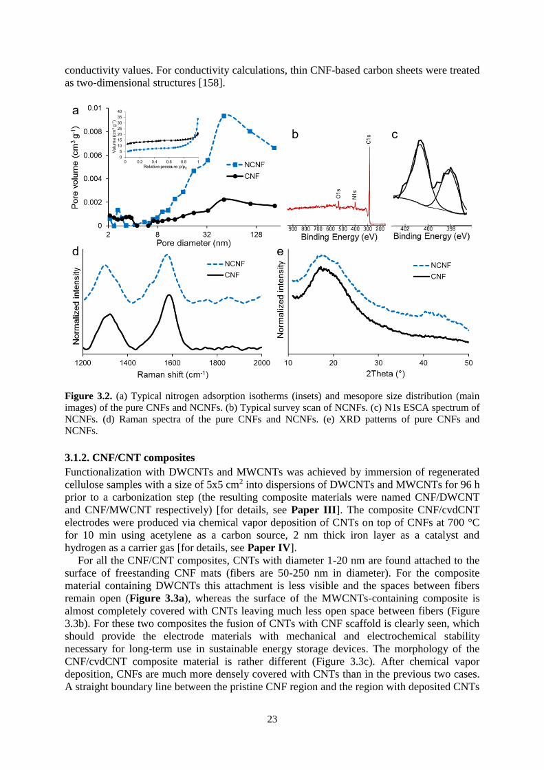
The NCNF materials have slightly lower surface areas than the pure CNF material (≈25 m2
g-1 vs 45 m2 g-1). The diameter of N-doped fibers is higher compared to the non-doped CNFs
due to the reduced loss of carbon, which explains the different values of the specific surface
area. In Figure 3.2a nitrogen adsorption isotherms and mesopore size distribution for the N-
doped electrode materials are shown. Referring to the International Union of Pure and
Applied Chemistry the nitrogen adsorption isotherms of this CNF-based material can be
characterized as type III isotherms. The shape of the isotherms is typical for pure carbons
without developed microporous structure which show small interaction potentials with an
adsorbate gas [151]. In addition, mesopore size distribution indicates that mesopores make up

22
a substantial fraction of the total pore volume for the NCNFs with open and accessible
structure.
Figure 3.1. SEM images of the functionalized CNF-based electrode materials: (a) CNF, (b) NCNF.
The electron spectroscopy for chemical analysis (ESCA) revealed that surfaces of all
NCNFs samples mostly consist of carbon, oxygen and nitrogen (Figure 3.2b). According to
ESCA, the nitrogen content is dependent on the concentration of NH4Cl and on the time of
impregnation. Manipulations with these two parameters allow synthesis of materials with a
gradient of nitrogen concentration. The longer time of impregnation and the higher
concentrations of NH4Cl result in the higher nitrogen incorporation. The typical N1s ESCA
spectrum of NCNFs is shown in Figure 3.2c. The spectrum has two major components: –N=
(398.2 eV) and –NH– (400.7 eV) which should be correspondingly related to nitrogen-
containing heterocyclic compounds such as pyridine and pyrrole/pyridone [152,153].
Nitrogen atoms can replace carbon atoms in aromatic five- and six-membered rings when
condensation process takes place during the carbonization of the cellulosic precursor at
temperatures above 400 °C [153,154]. N-doped samples also have a slightly higher amount of
oxygen containing groups (2.9 at.% for the pure CNFs and up to 5 at.% for NCNFs). It can be
assumed that due to weaker C–N bonds compared to C–C bonds the NCNFs are easier to
oxidize upon exposure to the air [153], which is reflected in the higher percentage of oxygen-
containing groups.
According to the Raman spectra shown in Figure 3.2d, all the samples demonstrate two
broad bands at ∼1320 cm−1 (D-band) and ∼1590 cm−1 (G-band) that can be correspondingly
assigned to in-plane vibrations of amorphous sp2-bonded carbon in structural defects and
crystalline sp2-bonded carbon [155]. Additionally, ID/IG ratios were used to assess the level of
disorder in the carbonaceous materials. For all the synthesized carbons the ratios are below or
slightly higher than 1.0, suggesting the presence of graphitic domains [156]. In comparison
with the pure CNFs, the N-doped samples have higher ID/IG ratios which increase along with
the increase in nitrogen content. This can be explained by the inclusion of nitrogen
heteroatoms into the graphite-like structure of CNFs, which generates more defects and thus
more disordered carbon lattice [157].
CNFs synthesized from the regenerated cellulose have amorphous structure (Figure 3.2e),
which is typical for carbon materials synthesized by carbonization of cellulose at temperatures
below 3000 °C [77]. Major amorphous peak can be recognized at 18-20° (002) and minor one
at 44° (110).
The influence of N-doping on electrical conductivity of CNF-based materials is almost
negligible, which is due to counteractive nature of incorporated nitrogen atoms [Paper II]. As
a result, N-doped samples with nitrogen content of 4.0 and 4.4 at.% have the highest
23
conductivity values. For conductivity calculations, thin CNF-based carbon sheets were treated
as two-dimensional structures [158].
Figure 3.2. (a) Typical nitrogen adsorption isotherms (insets) and mesopore size distribution (main
images) of the pure CNFs and NCNFs. (b) Typical survey scan of NCNFs. (c) N1s ESCA spectrum of
NCNFs. (d) Raman spectra of the pure CNFs and NCNFs. (e) XRD patterns of pure CNFs and
NCNFs.
3.1.2. CNF/CNT composites
Functionalization with DWCNTs and MWCNTs was achieved by immersion of regenerated
cellulose samples with a size of 5x5 cm2 into dispersions of DWCNTs and MWCNTs for 96 h
prior to a carbonization step (the resulting composite materials were named CNF/DWCNT
and CNF/MWCNT respectively) [for details, see Paper III]. The composite CNF/cvdCNT
electrodes were produced via chemical vapor deposition of CNTs on top of CNFs at 700 °C
for 10 min using acetylene as a carbon source, 2 nm thick iron layer as a catalyst and
hydrogen as a carrier gas [for details, see Paper IV].
For all the CNF/CNT composites, CNTs with diameter 1-20 nm are found attached to the
surface of freestanding CNF mats (fibers are 50-250 nm in diameter). For the composite
material containing DWCNTs this attachment is less visible and the spaces between fibers
remain open (Figure 3.3a), whereas the surface of the MWCNTs-containing composite is
almost completely covered with CNTs leaving much less open space between fibers (Figure
3.3b). For these two composites the fusion of CNTs with CNF scaffold is clearly seen, which
should provide the electrode materials with mechanical and electrochemical stability
necessary for long-term use in sustainable energy storage devices. The morphology of the
CNF/cvdCNT composite material is rather different (Figure 3.3c). After chemical vapor
deposition, CNFs are much more densely covered with CNTs than in the previous two cases.
A straight boundary line between the pristine CNF region and the region with deposited CNTs

24
validates reliable space controllable deposition of iron catalytic particles. Figure 3.3d reveals
slightly uneven growth of CNTs on different sides of CNF, which could be due to the
heterogeneous distribution of heat or catalytic particles within a CNF substrate during CNT
growth. The number of tube walls typically varied between 3 and 8, with rare occurrences of
single- and double walled tubes (Figure 3.3d, inset).
Figure 3.3. SEM images of the CNF/CNT composite materials: (a) CNF/DWCNT, (b)
CNF/MWCNT, (c) CNF/cvdCNT. TEM images of the CNF/cvdCNT.
All the CNF/CNT composites have higher surface area than the pure CNFs, especially big
difference is observed for the CNF/MWCNT and the CNF/cvdCNT materials (Table 3.1).
The increase in the values of CNF/CNT composite surface areas is due to the contribution of
attached CNTs with much higher individual surface area than 45 m2 g-1 of the CNFs. For the
pure DWCNTs used in this study the average specific surface area is estimated to be ≈730 m2
g-1, and for the pure MWCNTs – ≈300 m2 g-1 [159]. Nevertheless, the MWCNT-containing
material has higher specific surface area among two composites. Such a significant variance
in surface area contribution between DWCNTs and MWCNTs can be explained by the greater
adsorption of MWCNTs in comparison with DWCNTs during preparation of the
functionalized cellulosic precursor [Paper III]. Figure 3.4a shows pore size distribution for
the CNF/CNT materials. The shape of the isotherm is characteristic for meso- and
macroporous (pores with a size range of 2-50 and >50 nm, respectively) materials without a
developed microporous structure [151]. Mesoporous voids between incorporated CNTs are
very important for electrostatic energy storage as they provide sufficient access of electrolyte
ions to surface, support charge propagation and accumulation, and, as a result, increase power
capability of a supercapacitor [160]. Sufficient diffusion of electrolyte ions within pores of an
electrode material makes surface more available for EDL charge accumulation, and therefore
capacitance and power capability are not restricted [161]. Besides, aerial pore size distribution

25
points to the presence of pores with a diameter below 10 nm, which makes a substantial
contribution to the total surface area of the synthesized composites [Paper IV].
XPS analysis provides further characterization of the electrode surface. The analysis
confirmed that all the CNF/CNT materials almost completely consist of carbon (96-97%) with
predominant C–C bonds assigned to the peak at 284.5 eV (Figure 3.4b, main image).
Negligible amounts of polar heteroatoms makes the analyzed materials moderately
hydrophobic, which is indicated by the measured water contact angles of all the samples being
close to 90° (Figure 3.4b, inset). Taking into account that in this work an aqueous solution of
KOH was used as an electrolyte, hydrophobic materials such as the CNF-based may decrease
the distance of aqueous electrolyte ion diffusion to an electrode surface [56]. Despite this, the
wettability of the synthesized electrodes is not critically low to prevent fast diffusion of
relatively small OH- and K+ ions [162,163]. CNF-based materials have mesoporous structure
suitable for an unrestricted transport of ions within the material during charge/discharge
cycles.
Figure 3.4. (a) Pore size distribution of different CNF/CNT composites. Typical C1s XPS spectrum
(main image) and water contact angle inset) of the composites.
Addition of highly conductive CNTs also makes an impact on the electrical conductivity of
the synthesized composites presenting about 20 times higher values than for pristine CNFs,
(Table 3.1). For CNF/CNT composites, the higher conductivity of the CNF/MWCNT
composite indirectly indicates the higher amount of CNTs on its surface compared with the
CNF/DWCNT composite, which also agrees with the preceding assumption of better
adsorption of MWCNTs. The methods of composite electrode synthesis used in this research
work allow the surface of CNF scaffolds to be covered with continuous layers of conductive
CNTs. In all the composites the amounts of CNTs are big enough to reach the critical
percolation threshold, which explains such a high values of electrical conductivity for the
CNT-containing materials [164]. At the same time, functionalized samples retain 3D porous
network necessary for conductivity of the electrolyte ions [165]. Carbon materials that have
the prolific combination of high electrical conductivity and a large surface area with
developed mesoporosity are always desired in supercapacitors [20,166].
3.1.3. CNF/rGO composite
The beaker with cellulosic mats immersed into GO dispersion was subjected to continuous
gentle shaking for 2 days in order to get homogenous adsorption of GO flakes onto surface of
the cellulosic fibers. After the GO treatment, the cellulose/GO mats were dried in a fume hood
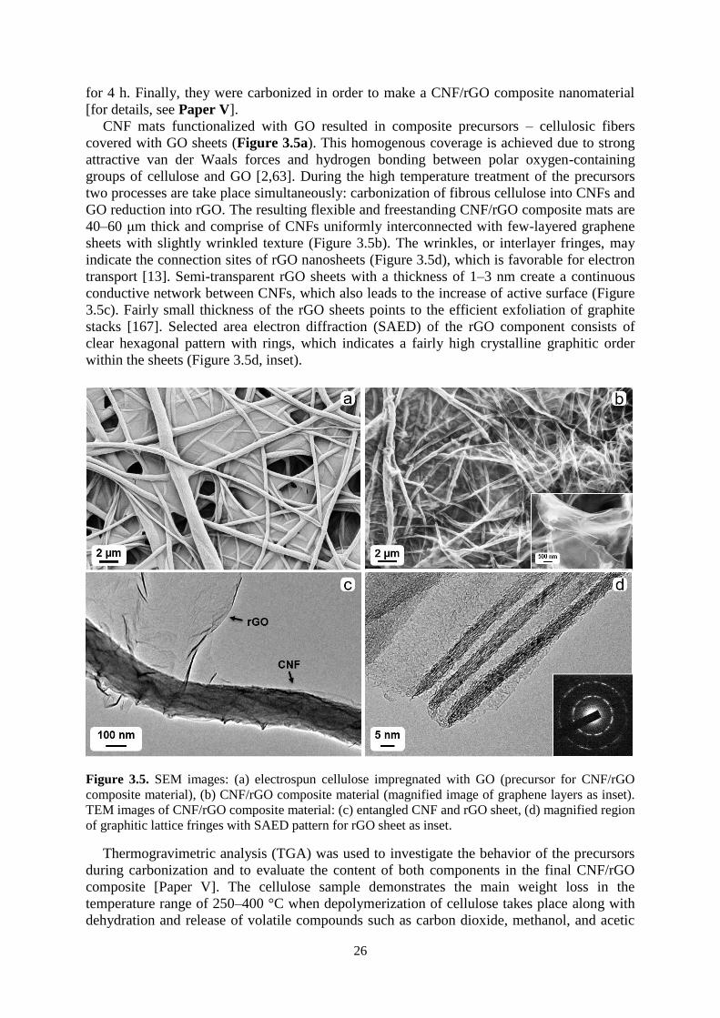
26
for 4 h. Finally, they were carbonized in order to make a CNF/rGO composite nanomaterial
[for details, see Paper V].
CNF mats functionalized with GO resulted in composite precursors – cellulosic fibers
covered with GO sheets (Figure 3.5a). This homogenous coverage is achieved due to strong
attractive van der Waals forces and hydrogen bonding between polar oxygen-containing
groups of cellulose and GO [2,63]. During the high temperature treatment of the precursors
two processes are take place simultaneously: carbonization of fibrous cellulose into CNFs and
GO reduction into rGO. The resulting flexible and freestanding CNF/rGO composite mats are
40–60 μm thick and comprise of CNFs uniformly interconnected with few-layered graphene
sheets with slightly wrinkled texture (Figure 3.5b). The wrinkles, or interlayer fringes, may
indicate the connection sites of rGO nanosheets (Figure 3.5d), which is favorable for electron
transport [13]. Semi-transparent rGO sheets with a thickness of 1–3 nm create a continuous
conductive network between CNFs, which also leads to the increase of active surface (Figure
3.5c). Fairly small thickness of the rGO sheets points to the efficient exfoliation of graphite
stacks [167]. Selected area electron diffraction (SAED) of the rGO component consists of
clear hexagonal pattern with rings, which indicates a fairly high crystalline graphitic order
within the sheets (Figure 3.5d, inset).
Figure 3.5. SEM images: (a) electrospun cellulose impregnated with GO (precursor for CNF/rGO
composite material), (b) CNF/rGO composite material (magnified image of graphene layers as inset).
TEM images of CNF/rGO composite material: (c) entangled CNF and rGO sheet, (d) magnified region
of graphitic lattice fringes with SAED pattern for rGO sheet as inset.
Thermogravimetric analysis (TGA) was used to investigate the behavior of the precursors
during carbonization and to evaluate the content of both components in the final CNF/rGO
composite [Paper V]. The cellulose sample demonstrates the main weight loss in the
temperature range of 250–400 °C when depolymerization of cellulose takes place along with
dehydration and release of volatile compounds such as carbon dioxide, methanol, and acetic

27
acid (Figure 3.6a) [144]. All these losses result in the low carbonizate weight yield of only
5.65% at 800 °C. Though for the cellulose/GO sample the weight loss starts at 150 °C, the
decomposition behavior is much less abrupt in comparison to the cellulosic sample. After
oxygen-containing groups are decomposed on the GO surface, the weight yield of the
composite is 23.53% at 800 °C. Of course, this tremendous increase of the yield for the
composite can be attributed to the presence of rGO with the characteristic weight yield of
around 40% after thermal reduction [168,169], however previously reported flame-retarding
characteristics of GO in polymeric composites may play even bigger role in preservation of
cellulose degradation [170].
Figure 3.6b shows XRD patterns of the precursors and the resulting carbon materials. The
XRD pattern of the cellulose sample contains three distinctive peaks at 12.1° (101), 20.0° (10-
1) and 21.9° (002) which are typical lattice planes of regenerated cellulose [171]. GO pattern
has a strong diffraction peak at 11.6° corresponding to turbostratic structure of GO layers. The
calculated interlayer spacing of the GO is 7.65 Å, which is much larger than the 3.34 Å
spacing of the (002) graphite lattice plane. Apparently, the distance is expanded due to the
incorporation of bulky oxygen-containing groups between graphite layers during GO
preparation [2]. The emerging broad peak at 26.1° and the disappearing peak at 11.6° for the
rGO point out the effective thermal reduction of GO which brings back the interlayer distance
close to the graphitic one (3.41 Å) and restores the π-conjugated system [63]. The pure CNFs
demonstrate a broad peak at 18-20°, which is typical for the amorphous structures obtained
after the cellulose carbonization [Paper I].
Due to the strong fusion between CNF network and graphene sheets in the final CNF/rGO
composite, the rGO layers act as perfect conductive connectors between CNFs. As a result,
the CNF/rGO composites have electrical conductivity of 49 S cm-1, which is about 10 times
higher than conductivity of the pure CNFs (4.2 S cm-1). Having such a high electrical
conductivity helps to avoid conventionally used fillers and volume-consuming redundant
binders thus substantially increasing the volumetric capacitance and energy density [18].
Moreover, all these leads to very low internal resistance and contact resistance with collectors,
which will be shown further in Section 3.2.
Figure 3.6. (a) TGA of cellulose and cellulose/GO. (b) XRD patterns of cellulose, GO, CNF/rGO and
CNF.
28
3.2. Electrochemical performance of CNF-based electrodes
In this thesis, two different electrochemical systems were implemented for electrochemical
evaluation of the CNF-based electrode materials. NCNFs and two CNF/CNT materials
(CNF/DWCNT and CNF/MWCNT) were tested in 3-electrode system, while CNF/cvdCNT
and CNF/rGO composites were tested in two-electrode system.
3-electrode system: CNF-based carbon nanomaterials were used as working electrodes, an
Ag/AgCl electrode was used as a reference electrode, a Pt net was used as a counter electrode
and aqueous solution of KOH was used as an electrolyte. The working electrodes were
punched out from the fibrous carbonaceous mats and had an area of 1 cm2. Prior to the
measurements the electrodes were kept in the electrolyte solution for 24 h and degassed with
N2 for 30 min. Electrochemical measurements were performed with a Gamry Reference600
potentiostat. A voltage range between -0.4 V and 0.4 V was used for the cyclic voltammetry
(CV) measurements and galvanostatic charge-discharge (GCD) tests. Electrochemical
impedance spectroscopy (EIS) was performed at open circuit potential with an amplitude of
10 mV over a frequency range from 100 kHz to 10 mHz. Electrochemical stability tests were
performed by potential cycling between -0.2 V and 0.2 V for 1000 cycles with a scan rate of
20 mV s-1.
2-electrode system: Symmetric Swagelok supercapacitor cells consisted of CNF-based
carbon nanomaterials as working electrodes, electrospun cellulose [Paper IV] or glass fiber
mats (Whatman) [Paper V] as separators, and 6 M aqueous solution of KOH as an electrolyte.
The working electrodes and separators were cut to a circular area of 0.5 cm2 [Paper IV] or 0.8
cm2 [Paper V] to fit current collectors (d = 1.2 cm). Before starting the measurements, the
electrodes were immersed in the electrolyte solution for at least 6 h. Electrochemical
measurements were performed with Gamry Reference 3000 potentiostat/galvanostat/ZRA. A
voltage range of 0–1.0 V was used for CV and GCD measurements. EIS was completed at an
open circuit potential with an AC amplitude of 5 mV over a frequency range from 100 kHz–
10 mHz. Electrochemical stability was evaluated via by cyclic charge–discharge (CCD)
measurements for 2000 cycles with a current density of 1 A g−1 [Paper IV] or for 4000 cycles
with a current density of 2 A g−1 [Paper V].
For the 2-electrode system, the evaluation of the material specific capacitance Cs (F g-1)
and the volumetric capacitance Cv (F cm-3) from the CV curves was made according to Eq 2
and 3, respectively (for the 3-electrode system factor of 4 was not used). The specific energy
density Ed (Wh kg-1) and power density Pd (W kg-1) were estimated from the GCD curves
following Eq 4 and 5, respectively. The volumetric energy density Edv (Wh L-1) and power
density Pdv (W L-1) were estimated from the GCD curves following Eq 6 and 7, respectively.
Cs = 4 ∫ I(V)dV
m∆Vs (2)
C𝜈 = 4 ∫ I(V)dV
v∆Vs (3)
Ed = I∆tV2
7.2m∆V (4)
Pd = 3600Ed
∆t (5)
Edv = I∆tV2
7.2v∆V (6)

29
Pdv = 3600Edv
∆t (7)
In the equations, ∫I(V)dV specifies the integrated area of the CV curves, i.e. current
response to voltage (A∙V), m is the total mass of two electrodes for the 2-electrode system and
the mass of a working electrode for the 3-electrode system (g) and v is the total volume of two
electrodes (cm3), ∆V is the potential window (V), s is the scan rate (mV s-1), ∆t is the
discharge time (s).
CV curves in Figure 3.7a-e demonstrate the typical scan rate dependence for the CNF-
based electrode materials. For all the materials, CV curves at lower scan rates show more
stable and moderately rectangular shape without apparent faradaic peaks within the potential
range used in the measurements. This indicates a reasonably good EDL capacitive behavior
with a fast current response on a voltage reversal and low resistance of ion transport within
the electrode [63, 172]. For higher scan rates, up to 100 mV s-1, distortion of the rectangular
shape takes place due to the increased resistance of electrolyte ion transport [13]. The CV
curves of the N-doped samples demonstrate a greater deviation from a rectangular shape,
which should be attributed to doping-induced faradaic reactions in the doped electrodes [173].
In Figure 3.7f the dependence of specific capacitance on the scan rate is shown. At 5 mV s-
1 specific capacitance is several times higher than at 100 mV s-1 for the all the electrode
materials. These differences are due to a lack of time for the electrolyte ions to diffuse to and
from the surface of the inner cavities of the electrode at the higher scan rates. The ions can
access only to the outer surface resulting in a smaller gathering of charge, whereas at the
lower scan rates they have time to occupy more of the available electrode surface and thus
provide a high accumulative charge [174]. The fact that even at the highest scan rate of 100
mV s-1 the materials retained about 70% of their initial capacitance, verifies the surface
accessibility of the synthesized materials, and hence the enhanced diffusion ability of the
electrolyte ions despite the hydrophobic nature of the surface [20].
Despite their lower values of surface area all the NCNFs show about 2.5 times higher
values of capacitance than the non-doped CNFs (measured in the 3-electrode system), which
could be attributed to a pseudocapacitance effect caused by doping [175,176]. For NCNFs,
the nitrogen content of 4-4.6 at.% can be regarded as an optimal range of doping that yields
the highest capacitances. This phenomenon correlates well with the electrical conductivity of
the electrode materials (Table 3.1). A plausible explanation to this behavior can be obtained
by considering two conflicting processes induced by the incorporation of nitrogen atoms into
the graphitic domains in the CNFs. On the one hand, these nitrogen atoms promote n-type
conductivity (via the donation of electrons into delocalized π-system of carbon atoms) and
pseudocapacitance (via redox reactions of nitrogen-containing groups). On the other hand, the
inclusion of nitrogen generates more defects and increases scattering in graphitic domains
leading to a less conductive material [146]. At some optimal atomic concentration of nitrogen
these two processes provide a material with a peak electrochemical performance.
As expected, CNFs functionalized with MWCNTs and DWCNTs reveal superior specific
capacitance in comparison with the pristine CNF. Regardless of the substandard surface area
for supercapacitor electrode materials, the capacitance values of both composites are among
the highest ones shown by the reported electrodes based on plant cellulose
[13,55,56,177,178]. Such a high results can be explained by the steady incorporation of CNTs
into the CNF scaffolds, which significantly improves the electrical conductivity of the
material and allows all the surface area to be active and accessible for charge accumulation
[60]. However, it should be mentioned that these two electrode materials were only tested in
the 3-electrode system. It is known that 3-electode systems with a single working electrode
have intensified sensitivity, which can result in large deviations of electrochemical values
from a real supercapacitor cell consisting of two electrodes [179].

30
Figure 3.7. CV curves of different electrode materials tested in 3-electrode systems ((a) NCNFs and
(b) CNF/MWCNT) and 2-electrode systems ((c) CNFs, (d) CNF/cvdCNT and (e) CNF/rGO). (f)
Combined capacitance dependence on scan rate.
The CNF/cvdCNT composite electrodes show about two times higher values of
capacitance in comparison to the pure CNF electrodes. Similar to the previous CNT-
containing composites, addition of CNTs has a big influence on the performance of the CNF-
based electrodes as CNTs significantly increase their surface area and electrical conductivity
(Table 3.1), which are key factors in making electrostatic charge accumulation process more
efficient [14].
For the composite CNF/rGO electrodes big attention is also paid to their volumetric
capacitance values which are found to be very promising (46 F cm-3). The thickness of these
ele (40-60 μm) is comparable to that of commercial electrodes (100-200 μm), which makes
these values trustworthy [180]. Despite having much lower specific surface area than common
electrodes made of activated carbons, the volumetric capacitance value of the CNF/rGO
composite stands very high among the reported carbon electrodes and conducting polymer-
based electrodes [19,181], This outstanding performance can be explained by three possible

31
factors: 1) relatively high packing density (≈ 0.5 g cm-3) of the material due to its low porosity
[180]; 2) really high electrical conductivity due to the absence of a binder material and
apparently due to abundant conductive interconnections between rGO sheets and CNFs,
which facilitates effective charge transfer throughout the material; 3) reorganization of rGO
sheets during intercalation of electrolyte ions, which leads to a higher accessible surface area
[182].
Furthermore, GCD measurements were used to investigate the electrochemical behavior of
the electrode materials. From these measurements their ability to accumulate electrical energy
(energy density) and release it within a certain time frame (power density) can be estimated.
Energy density and power density are among the most essential characteristics of a
supercapacitor.
Figure 3.8 represents the typical GCD curves of the electrodes at different current
densities. All the charge/discharge curves show the linear nearly symmetrical shape
specifying pure EDL capacitive behavior. Small deviations from a triangular shape in the
beginning of the discharge curves are attributed to the IR drop which arises due to the
equivalent series resistance (ESR) within the system [12]. The specific capacitance decreases
with an increasing current density, which correlates with the CV measurements where the
specific capacitance decreases with an increasing scan rate.
GCD curves of the NCNFs and CNF/MWCNT electrodes tested in 3-electrode system
show their fast current-voltage response (Figure 3.8a-b), which is a vital characteristic feature
for supercapacitors with high power density. In general, these two electrode types have
relatively short time of response in comparison to previous studies [17,173]. Very short
charge/discharge time for NCNFs can be explained by their rather low capacitance; while for
the CNT-containing electrodes fast current-voltage response can be the outcome of their
excellent electrical conductivity and developed porous structure which facilitates the
electrolyte ion transport decreasing the time of charge/discharge cycle to just a few seconds.
GCD curves of the CNF/cvdCNT and CNF/rGO electrodes tested in 2-electrode system show
relatively different behavior in terms of current-voltage response, which is typical for real
supercapacitor devices (Figure 3.8c-d).
From the GCD test power and energy density values were found to be reasonably high for
the composite electrode materials (Table 3.1). The specific capacitance, as well as energy
density, is dependent on current density. For instance, at 10 A g-1 the values of specific
capacitance of the CNF-based composite electrodes are about 40% higher than the ones at 0.5
A g-1, which is due to their fairly large thickness and subsequent inability of the electrolyte
ions to diffuse quickly enough to the inner cavities at the higher current density [182], which
negatively effects accumulation of charges, i.e. decreases capacitance [174]. These GCD
results are consistent with the dependence of specific capacitance on a scan rate shown by the
CV measurements. The ions need to be as close as possible to the electrode surface in order
for a supercapacitor to maintain high rate capability, and non-porous CNFs are not able to
keep ions attached to the surface. On the contrary to them, highly conductive components
such as rGO sheets or CNTs can retain ions within nanometer sized voids, thus creating ion-
buffering reservoirs and reducing ion diffusion length. These confined ions have instant
access to the electrode surface even at the highest current density [183]. High rate capability
is very important for compact supercapacitors with volumetric limitations [181].

32
Figure 3.8. GCD curves of the functionalized electrode materials tested in 3-electrode systems ((a)
NCNFs and (b) CNF/MWCNT) and 2-electrode systems ((c) CNF/cvdCNT and (d) CNF/rGO).
The electrochemical behavior of the electrode materials was further analyzed with EIS
which helps to describe important electrochemical characteristics such as charge transfer
resistance (Rct), which arises mostly due to the electron transfer events or faradic processes
[184], and ESR, which mostly comprises of bulk electrolyte resistance (Rs) and interfacial
resistance between an electrolyte and an electrode material [185].
Figure 3.9 shows Nyquist plots of all the measured samples. In the high frequency region
ESR is expressed as an initial intercept of the plot with the X-axis, while charge transfer
resistance is expressed as an intercept of a semicircle with the X-axis [185,186].
The ESR values for the samples measured in the 3-electrode system are around 7.5 Ω
(Figure 3.9a), which are very high values that might be attributed to very high Rs due to the
use of KOH electrolyte with low concentration of 1M. Rct vary between the samples,
indicating a difference in electrolyte ion interaction for the different electrode surfaces. For
the NCNFs the Rct is in the range of 2-6 Ω depending on the doping content [Paper II]. The
smaller semicircle on the plot of the pure CNF electrode in comparison with the CNT-
containing composites indicates a facilitated ion-surface interaction of the pristine sample
[187]. The reason of this difference might be to some extent hindered diffusion ability of the
electrolyte ions to travel through the layer of the entangled CNTs from the aqueous solution to
the electrode surface. This hypothesis also suggests that Rct of the CNF/MWCNT composite
is higher than that of the CNF/DWCNT due to the denser layer of CNTs covering the
electrode surface of the CNF/MWCNT composite. In addition, Figure 3.9b shows Nyquist
plots in the low and medium frequency regions. In these regions, the slope of the 45° segment
of the curve is known as Warburg impedance which is used to analyze the resistance within a
porous electrode material. The shorter the line is the less hindered is the ion diffusion path
within an electrode. The short length of the Warburg lines of all the samples demonstrates

33
their enhanced pore accessibility for the electrolyte ion diffusion and nearly ideal EDL
capacitive behavior [20,56].
Figure 3.9. Nyquist impedance plots of the electrode materials tested in 3-electrode systems
(a-b) and 2-electrode systems (c-d) at higher frequency and at wide range frequency.
On the contrary to the measurements in the 3-electrode system, the ESR values for the
samples measured in the 2-electrode system are below 1 Ω (Figure 3.9c), which are
satisfactory values for effective supercapacitor devices. Though the same electrolyte solution
is used for the cells with different electrodes, the one containing the CNF/rGO electrode has
lower ESR (0.16 Ω) than the one containing the pure CNF (0.38 Ω) or the CNF/cvdCNT
composite (0.57 Ω). It is due to the fact that Rs is determined not only by the conductivity of
the electrolyte, but also by the thickness of its layer [2]. Apparently, the electrolyte layer
between rGO sheets is thinner, which is due to ion-buffering reservoirs mentioned previously.
Whereas a slightly higher value for the CNF/cvdCNT material can be explained by its slightly
worse wettability with the aqueous KOH electrolyte due to the negligible amount of
hydrophilic oxygen-containing groups (according to the XPS analysis in Paper IV). What is
more important, Rct is very low for both types of the composite electrodes compared to the
pure CNF electrodes (≈ 0.5 Ω for the CNF/cvdCNT, 0.35 Ω for the CNF/rGO, and ≈ 1 Ω for
the CNFs. Very low value of Rct can be attributed to few characteristic features of the
composite materials: their hierarchical meso- and macroporosity, which decreases the
interfacial resistance between the electrolyte and the electrode material (ionic resistance), and
their high conductivity and binder-free elastic nature, which decreases intrinsic resistance and

34
resistance between the electrode material and the collectors (electronic resistance) [66].
Figure 3.9d shows Nyquist plots in the medium-low frequency region, where the short
Warburg region along with good line verticality indicate the composite electrodes’ proper
pore accessibility for the electrolyte ion diffusion and flawless EDL capacitive behavior [2].
In general, EIS results agree very well with the GCD tests in terms of time needed for the
electrolyte ions to diffuse to an electrode surface during charge/discharge cycles.
To validate the long time usage of the electrode materials, electrochemical cycle stability
tests were performed for thousands of cycles to resemble the work of a real capacitor. Having
a good cyclic stability is very important for supercapacitor since it has continuously to deliver
the harvested energy in short intervals through rapid charging and discharging [188]. In
Table 3.1 the cyclic stability of the synthesized materials is listed. In the 3-electrode system,
the pure CNFs and the CNFs functionalized with MWCNTs and DWCNTs show good
retention of their initial capacity (93-95%) after 1000 cycles, which indicates satisfactory
cycle stability of this type of composites. This ability to withstand a big number of
charge/discharge cycles without worsening performance confirms strong fusion between CNF
scaffold and incorporated CNTs, which remains stable throughout the experiment. In contrast,
the N-doped samples even show a continuous increase in capacitance over the 1000 cycles
that may be due to successive diffusion of positively charged potassium ions (K+) during the
cyclic stability test into the spaces within the structure of the electrodes through the defects
created by N-doping. Besides that, for positively charged ions it should be energetically more
favorable to attach closer to the N-doped sites with higher electronegativity [189]. In
comparison to the N-doped samples, the pure CNFs and CNF/CNT composites only have
intrinsic defects, which may be the reason why their capacitance is more stable.
In the 2-electrode system, the CNF/cvdCNT electrodes retain 96.6% of the initial
capacitance after 2 000 cycles. Strong adhesion of vapor-grown CNTs to CNFs is confirmed
by such an excellent stability of the composite. The device with the CNF/rGO electrodes
retain even higher capacitance – 97% over 4000 cycles, while for the ones with the pure CNF
electrodes it even goes up to 106% of their initial capacitance. The latter result is most
probably related to etching, i.e. activation, of the CNF electrodes at the initial part of the
cycling [181].
Overall, in both systems electrodes demonstrate superb capacitance retention, which
confirms great electrochemical stability of all the CNF-based materials and the huge potential
of CNFs as a matrix for efficient composite electrodes.
Table 3.1. Properties of the electrode materials.
Electrode
material
Specific
surface area
(m2 g-1)
N
content
(at.%)
Electrical
conductivity
(S cm-1)
Specific
capacitance
(F g-1)
Energy
density
(W h kg-1)
Power
density
(kW kg-1)
Capacitance
retention
(%)
Papera
CNF3s 45 - 4.2 11 0.035 3.2 93 II,III
NCNF 21-29 4.0-5.6 6.3-10.2 21-28 ≈0.6 2.1-6.8 133-145 II
CNF/DWCNT 60 - 85.3 163 3.6 24.8 94 III
CNF/MWCNT 168 - 98.2 241 4.1 19.6 95 III
CNF2s 45 - 4.2 47 1.2 1.7 106 IV,V
CNF/cvdCNT 131 - 69.4 92 2.6 2.0 97 IV
CNF/rGO 143 - 49.0 102 1.3 2.4 97 V
aParameters of electrochemical measurements varied for different electrode materials. See details in the referred papers.
35
This study shows that limitations such as deficient values of surface area and electrical
conductivity of fibrous electrode materials derived from cellulosic precursors can be greatly
reduced by the functionalization: N-doping, incorporation of CNTs via impregnation or vapor
growth, coverage with rGO. Carbon composite materials are designed in a way to combine
the beneficial properties of its constituents. Inclusion of nitrogen heteroatoms can improve
capacitive performance via pseudocapacitive effect. CNTs and rGO enhance active surface
for charge accumulation with high packing density, while their high electrical conductivity
results in low charge transfer resistance. At the same time, freestanding and mesoporous
nature of CNFs as the main component provides convenient handling and sufficient ionic
transport through the electrodes. I believe that these sustainable electrodes for supercapacitors
can be viewed as legitimate future substitutes to commonly used electrodes made of
exhaustible resources.

36

37
Chapter 4
Conductive scaffolds for neural TE
The cell line used in this study was SH-SY5Y, originating from a bone marrow biopsy of a
patient suffering from neuroblastoma. This cell line is commonly used as a neuronal model
since it is characterized by a high proliferation capacity and a homogenous cell population.
Furthermore, these cells can also be subjected to differentiation in order to acquire the
functional phenotype of mature neurons [190,191]. Details of cell culturing, seeding, growth
and differentiation are described in Papers VI and VIII, as well as experimental procedures of
cell fixation for SEM, cell staining for confocal microscopy and cytotoxicity assays.
4.1. 2D fibrous scaffolds
In the following section, synthesized 2D scaffolds, i.e. material sheets without controllable
3D patterns on the surface, are evaluated and compared with regard to their influence on
neural tissue development. This development is greatly dependent on the scaffold surface
properties, such as topography, hydrophilicity and electrical conductivity. To compare the
responses of the neural cells to different scaffold properties, the following cell parameters are
used in this study: cell adhesion to surface, neurite extensions from soma and intercellular
connectivity.
4.1.1. Scaffold properties
Morphology and topography of the scaffold materials were evaluated using SEM and
AFM, respectively (Figure 4.1). Figure 4.1a shows the pure cellulose scaffold. It has an open
fibrous structure with a range of fiber diameters between 300 nm and 1500 nm. The fiber
surface is smooth according to the AFM image. Figure 4.1b clearly demonstrates that
functionalization of cellulose with CNTs results in a material with totally different
topography. Electrospun cellulosic material is densely covered with CNTs in a range of
diameters between a few nanometers to 20nm. AFM image reveals that the nanotubes provide
the fiber surface with a fairly high roughness at the nanometer level. Figure 4.1c shows the
CNF material obtained after carbonization of cellulosic precursor according to the
experimental procedure described in Paper I. The morphology of this scaffold material is
similar to the pure cellulose, except for the smaller diameter of the fibers (50-250 nm), which
also makes the CNF scaffold denser than the cellulosic precursor. The shrinkage of the fibers
is due to the loss of material during pyrolysis discussed in details in Paper I.
Nanometer dimensions of the CNFs and, especially, CNTs should make these two
cellulose-derived materials effective scaffolds for neural TE. Such scaffolds can provide
contact guidance to cells through topological features in the nanometer range, which can be
reflected in enhanced cellular adhesion, migration and differentiation. The mechanism of cell
responsiveness to nanosized surface features involves the formation of focal adhesions
between cell transmembrane proteins (integrins) and ECM providing intracellular-
extracellular connectivity. Integrins have a size range of 10-20 nm, and that is why they prefer
to interact with scaffolds that have topological features, such as roughness or diameter, with a
relatively similar size (usually up to few hundred nanometers) [192,193]. For the
cellulose/CNT samples, the surface is substantially covered with the aptly sized CNTs (≈5–20
nm), creating a rough surface with a large amount of available anchoring points In the case of
the CNF material, a small diameter of fibers (around 100-200 nm) are supposed to have a
positive effect on cell behavior.
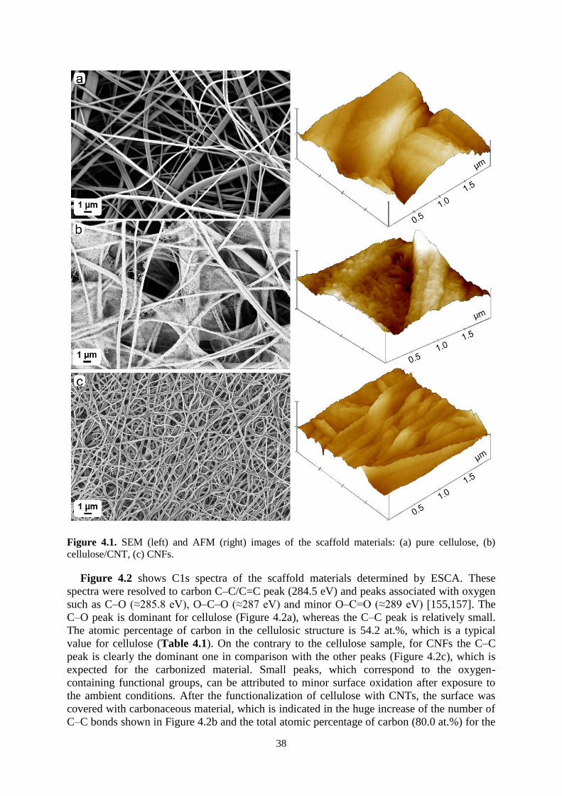
38
Figure 4.1. SEM (left) and AFM (right) images of the scaffold materials: (a) pure cellulose, (b)
cellulose/CNT, (c) CNFs.
Figure 4.2 shows C1s spectra of the scaffold materials determined by ESCA. These
spectra were resolved to carbon C–C/C=C peak (284.5 eV) and peaks associated with oxygen
such as C–O (≈285.8 eV), O–C–O (≈287 eV) and minor O–C=O (≈289 eV) [155,157]. The
C–O peak is dominant for cellulose (Figure 4.2a), whereas the C–C peak is relatively small.
The atomic percentage of carbon in the cellulosic structure is 54.2 at.%, which is a typical
value for cellulose (Table 4.1). On the contrary to the cellulose sample, for CNFs the C–C
peak is clearly the dominant one in comparison with the other peaks (Figure 4.2c), which is
expected for the carbonized material. Small peaks, which correspond to the oxygen-
containing functional groups, can be attributed to minor surface oxidation after exposure to
the ambient conditions. After the functionalization of cellulose with CNTs, the surface was
covered with carbonaceous material, which is indicated in the huge increase of the number of
C–C bonds shown in Figure 4.2b and the total atomic percentage of carbon (80.0 at.%) for the

39
cellulose/CNT sample. However, the substantial presence of oxygen (incorporated into C–O
and O–C–O bonds) indicates the traces of uncovered spots of cellulose.
The measurements of advancing water contact angles show a good correlation with the
chemical composition of the surface determined with ESCA for the same scaffold materials
(Figure 4.2 (insets) and Table 4.1). Pure cellulose has a very low contact angle of 14.6°
typical for the highly hydrophilic nature of cellulose, which is attributed to a strong influence
of abundant polar OH groups (correspond to C–O peaks in C1s spectra) [25]. Treatment of
cellulose with CNTs results in a sample with a higher contact angle (34.3°) due to the
influence of hydrophobic CNTs [194]. However, the surface still remains considerably
hydrophilic as its coverage with CNTs is not homogeneously dense or too thin, which is
consistent with the ESCA analysis. CNF is the most hydrophobic scaffold material in this
study as it has low amount of polar groups on the surface according to ESCA. The earlier
studies have proven that the more hydrophilic the surface of the material is, the greater the
enhancement of cell adhesion is [195].
Figure 4.2. C1s ESCA spectra and water contact angles (insets) of the scaffold materials: (a) cellulose,
(b) cellulose /CNT, (c) CNFs.
Table 4.1 provides the values of electrical conductivity for all the scaffold types. The
untreated cellulose sample, as a typical insulator material [196], demonstrates very low value
of electrical conductivity. In contrast, the CNT-functionalized cellulose sample has about a
105 times higher conductivity value, which confirms that the amount of CNTs on top of
cellulose is sufficient to reach the critical percolation threshold and enable the movement of
an electric charge [164]. The CNF samples show much higher value of electrical conductivity,
which is about 107 times higher than the unmodified cellulose material. Taking into account
the electrical properties of neural cells, stimulus-responsive scaffolds with electrical activity
are expected to promote neuron contact guidance, growth and differentiation of neurons.
Conductive carbon nanomaterials are thought to excite the electrical activity of neurons,
which leads to an increased functional expression of signaling receptors and nerve growth
factor proteins. These receptors and proteins may in turn be involved in a mechanism that
changes neuronal migratory phenotype to synaptic connectivity, i.e. differentiation of neural
cells into mature neurons is occurring [197,198]. Ostrakhovitch et al. previously showed the
dependence of neural differentiation on the degree of scaffold conductivity, indicating that the
higher scaffold conductivity results in an enhanced differentiation of neurons [199].
According to cytotoxicity analysis, the cellulose and CNF scaffold materials show
extremely good biocompatibility with cell viability above 90% (Table 4.1). The sample
containing CNTs can be considered potentially cytotoxic as the cell viability rate was only
about 40%. The viability threshold for the cytotoxicity analysis is 70%. This study confirms
the biocompatibility of the pure cellulose sample shown previously [44,45]. In contrast, it has
previously been shown that carbonaceous nanostructures can cause a cytotoxic response due

40
to issues such as residual metal catalysts or dispersants left from their preparation,
functionalization with carbonyl, carboxyl or hydroxyl groups, inappropriate length for
integration into phagocytes, and a needle-like shape [38,200]. All these factors may be valid
in our study regarding the CNT-modified samples, which led to a decrease of the cell viability
on this scaffold material. The successful example of the CNF material demonstrated the
importance of a preparation technique for carbon materials, as none of the negative cytotoxic
factors seem to concern the CNFs obtained by carbonization of electrospun cellulose. This
synthesis method allows the formation of a continuous fiber network made essentially of pure
carbon, which proves to be totally non cytotoxic.
Table 4.1. Properties of the scaffold materials.
Sample C (at.%) O (at.%) Water contact
angle (°)
Electrical
conductivity (S cm-1)
Cell
viability (%)
Cellulose 54.2 55.8 14.6 7.8·10-7 90.1
Cellulose/CNT 80.0 19.3 34.3 1.8·10-1 38.3
CNF 96.4 3.6 87.2 11.2 95.6
4.1.2. Cell development on 2D scaffolds
SH-SY5Y cells were differentiated for 15 days on the conductive cellulose/CNT and CNF
scaffolds, while the pure cellulose was used as a control. In order to obtain a clear view of the
differentiation progress and general interaction with the scaffold material, analyses were made
at different distinct time points: 5 and 15 days of differentiation.
SEM images of cells on the analyzed scaffolds are presented in Figure 4.3. These images
show a representative view of cell adhesion and morphology after 5 days of differentiation.
On the pure cellulose scaffolds cells mostly form aggregates rather than spread on the scaffold
surface (Figure 4.3a). In contrast, on the conductive scaffolds one can observe considerable
cell spreading and the formation of long neurites extending from soma, which is typical
neuronal-like morphology and a good sign of cell communication (Figure 4.3b-c). More dead
cells are detected on the cellulose/CNT scaffolds (Figure 4.3b), which agrees with the
cytotoxicity results.
Confocal microscopy is a necessary tool for the investigation of cell morphology
throughout the differentiation. This type of analysis clearly indicates the neurite extensions
from soma. These neural processes are characterized as very thin fiber-like assemblies that are
difficult to identify with SEM due to the resembling fibrous environment. Rhodamine-
phalloidine is used to stain cell cytoplasms in red and DAPI is used to stain cell nuclei in blue.
Figure 4.4 shows the SH-SY5Y cells on different scaffolds after 15 days of culturing. The
cells on the cellulose scaffolds assemble in large aggregates. Cells have poorly developed
cytoplasm and very few neurite extensions (Figure 4.4a). On the other hand, cells on the
conductive surfaces have morphology that is similar to the one that mature neurons have,
which is well shown in images with higher magnification (Figure 4.4b-c). Cell cytoplasm is
much larger in comparison with the cells grown the pure cellulose scaffolds. Moreover,
noticeable extensions connect the neighboring cells and promote cell network formation
[Paper VI].

41
Figure 4.3. SEM images of SH-SY5Y cells on the pure cellulose (a), cellulose/CNT (b) and CNF (c)
scaffolds after 5 of culturing (magnifications: 1.000× (main images) and 5.000× (insets)).
Despite good biocompatibility and hydrophilicity, cells on the untreated cellulose scaffolds
grow in large clusters and exhibit no signs of differentiation throughout 15 days of cell study.
These results suggest that neural cell behavior on scaffolds is more dependent on other factors
such as surface topography and electrical conductivity of scaffold materials. The electrospun
cellulose material lacks these advantageous features on the contrary to the cellulose/CNT and
CNF materials. Cell differentiation towards mature neurons is distinctively better on
electrically conductive scaffolds with nanotopographical features. Already within 5 days of
differentiation, cells start to form a network, which is a pleasing result for SH-SY5Y
neuroblastoma cells [191].
This TE research proves that conductive cellulose-derived nanofibrous materials can be
effective scaffolds for neural tissue development, which should contribute to the treatment of
neurodegenerative disorders and the construction of sustainable drug screening models [Paper
VI].

42
Figure 4.4. Confocal microscopy images of SH-SY5Y cells on the pure cellulose (a) cellulose/CNT
(b) and CNF (c) scaffolds after 15 days of culturing. Cell nuclei stained with DAPI appear in blue;
actin filaments of cytoplasm stained with rhodamine-phalloidin appear in red.
43
4.2. 3D printed scaffolds
In the following section, 3D printed scaffolds, i.e. material sheets with well-regulated 3D
patterns on the surface, are prepared, characterized and evaluated with regard to their ability
to enhance and guide neural tissue development. Similar to the previous section, scaffold
surface properties such as topography and electrical conductivity are taken into account as the
most influential ones.
Recent studies showed that 3D frameworks improve neural differentiation and cell
survival. One reason for that can be a higher spatial freedom for cells to interact with other
cells and matrix within such 3D constructs compared to cells grown on flat 2D scaffolds
[41,201,202]. At the moment, 3D printing offers the biggest variety of options for 3D
manufacturing. 3D printing is a facile method that allows production of materials with
advanced functionality, versatile design and precise reproducing architecture. From
sustainability point of view, the technique produces minimal resource waste and can utilize
biocompatible biopolymer inks for the assembly of bulk structures [Paper VII-VIII,203].
4.2.1. Optimization of conductive inks for 3D printing
Ink printability is mostly determined by its composition and rheological properties. In order to
provide a homogeneous steady structure at the end, the components of a composite ink must
be well dispersed and compatible with each other and a dispersing solvent. Besides, the flow
of an ink is supposed to be smooth in the printer, while after deposition from a printer nozzle
a desired shape has to be maintained [204].
NFC-based hydrogel inks can satisfy the above-mentioned requirements for the production
of 3D printed structures. After chemical and mechanical pretreatment, wood fibers can be
disintegrated into nanofibrils that form a stable aqueous dispersion at 2 wt.%. Furthermore,
the introduction of negatively charged deprotonated carboxyl groups to the fibril surface
provides strong electrostatic repulsion between nanofibrils and thus prevents their aggregation
[49,51]. That is why at the concentration of 2 wt.% relatively weak gel network of entangled
fibrils can be easily disrupted upon applied shear stress [205]. Viscosity of the NFC ink
decreases upon increased stress or shear rate (Figure 4.5), i.e. shear thinning effect takes
place, and the ink starts to flow inside a printer nozzle. Outside the nozzle stress is released
and shear viscosity of the ink goes back to its initial high value due to intermolecular
association of NFC [Paper VIII]; a 3D printed structure solidifies either in its intact shape or
collapses in a controlled manner [Paper VII].
In order to make an electrically conductive ink, NFC hydrogels are mixed with CNTs. This
is the first reported NFC/CNT composite ink for 3D printing [Paper VII]. The common
method to achieve the dispersibility of hydrophobic CNTs in water relies on the addition of
surfactant molecules to the mixture [206]. Unfortunately, ionic surfactants are detrimental to
living cells [207] and, besides, they decrease the conductivity of CNT-containing composites
[206]. Using carboxylated CNTs with negatively charged carboxylic groups can partially
solve the problem of CNT dispersibility in water by establishing repulsive forces between
CNTs [208]. It has been shown previously that charged NFC can also act as an aqueous
dispersion agent for CNTs via long-range electrostatic repulsion and short-range hydrophobic
interactions [53]. In this study, respective ζ-potentials for NFC and CNT dispersions are -33.4
and -58.8 mV, which results in strong repulsion between nanofibrils and nanotubes. The
composite ink has ζ-potential of -40.2 mV (pH = 6.5), however it is not printable due to its too
low viscosity caused by higher negative charge within the ink compared to the pure NFC ink
[Paper VIII]. The addition of NaOH moderatly decreases electrostatic repulsion between
colloidal particles (ζ-potential = -34.5, pH = 8.5), which leads to satisfactory rheological
properties for 3D printing (Figure 4.5). It is assumed that in the resulting composite
NFC/CNT ink specific interactions of Na+ counterions with deprotonated carboxyl groups

44
have stronger effect on the overall charge than the increased degree of carboxylic dissociation
at higher pH [Paper VIII,209].
Figure 4.5. Flow curves of the different inks.
4.2.2. Scaffold properties
A 3D printer (RegenHU 3D Discovery) was used to form 3D scaffolds through a piezoelectric
microvalve and a 300 μm nozzle. The printing time of one batch of scaffolds was around 10 s
(Figure 4.6a). The structures were printed on the robust NFC film substrates. The scaffolds
were air-dried at ambient conditions for 24 h. The dry NFC-based scaffolds have few
advantages for in vitro TE analysis in comparison with bioprintable hydrogels: 1) strong
cross-linking is not required immediately after printing due to prevailing attractive van der
Waals forces upon reaching certain critical concentration during drying [210], 2) possibility to
use charge-stabilized NFC/CNT inks with presumably cytotoxic carboxylic groups which
disappear after drying [200,207], 3) wide fabrication window on the contrary to tough
physical and biological requirements imposed on bioinks [204].
Morphological and topographical features of the printed scaffolds were evaluated using
various microscopy methods. Figure 4.6c-d show guidelines 3D printed with the pure NFC
ink and the conductive NFC/CNT ink. The lines are 2-3 times as wide as the nozzle diameter
of 300 μm, while their height is around 10 μm (Figure 4.6b), which is 30 times lower than the
initially deposited one. This controllable collapse can be considered as a benefit since it
increase the printing resolution after water evaporation without any technical modifications
[Paper VII]. Nevertheless, the width of guidelines below 1 mm can be achieved even without
cross-linking, and the height of guidelines around 10 μm cannot hinder free cell migration
throughout the scaffold. AFM images show that topography of guidelines printed with two
different inks is very similar and is characterized uniform fibrils (Figure 4.6e-f). It is
impossible to differentiate cellulosic nanofibrils and SWCNTs from each other due to their
almost identical diameter of, i.e. 3-6 nm and 4-5 nm, respectively [48,49].

45
Figure 4.6. (a) Schematic drawing of printed two layers with an offset resulting in a step (wet state).
The lower SEM image shows the dried structure corresponding to a red square in the schematic image
above. (b) 3D printed NFC/CNT guidelines on a pure NFC substrate film. SEM images of guidelines
3D printed on NFC substrates using (c) the pure NFC ink and (d) the composite NFC/CNT ink (mag =
100 ×). AFM images of the guidelines 3D printed using (e) the pure NFC ink and (f) the composite
NFC/CNT ink.
3D printed composite guidelines have electrical conductivity of 3.8·10-1 S cm-1, while
reference guidelines from pure NFC ink show isolative behavior. The volume fraction of
CNTs in the composite ink equals 21.7 vol.%, which is definitely sufficient amount to reach a
percolation threshold after drying at ambient conditions without any pressure manipulations,
increased velocity of injection or temperature [208].
Hierarchical structure of wood cellulose with nanoscale order and orientation of fibrils
along the fiber axis are the reasons why the printed NFC structures form a densely packed
aggregate with very high elastic modulus of around 4.3 GPa upon drying [211]. The addition
of CNTs to an ink results in the structure with the modulus up to 5.7 GPa, which should be
attributed to very sufficient dispersibility and directed orientation of CNTs during dispensing
[208].

46
4.2.3. Cell development on 3D scaffolds
The Live/Dead staining is used to determine cell attachment, proliferation and survival after
10 days of culturing on the scaffolds (Figure 4.7a). Cells on the composite NFC/CNT
scaffolds have exceptional proliferation and spreading exactly along the guidelines, while it is
hard to find any cells on the pure NFC substrates. At the reciprocal scaffold, i.e. with 3D
printed pure NFC guidelines on the NFC/CNT substrate, such a significant difference in cell
proliferation on two different surfaces is confirmed as cells stay committed to the NFC/CNT
material and abandon the pure NFC material (Figure 4.7b).
Cell behavior on the conductive NFC/CNT guidelines after 10 days of culturing is further
evaluated using SEM and confocal microscopy. SEM images reveal good cell adhesion to the
scaffold surface and clear signs of cell communication via extension of neurites between
neighboring cells (Figure 4.7c). Confocal microscopy image demonstrates neuronal-like
dendritic morphology of cells along with their elongated neurites (Figure 4.7d), which is the
indication of cell differentiation [212].
Figure 4.7. (a) Live/Dead staining of cells after 10 days of culturing on guidelines 3D printed using
the composite NFC/CNT ink. Green fluorescent spots indicate alive cells and red fluorescent spots
indicate dead cells. (b) Fluorescence microscopy image of cells cultured on the reciprocal scaffold
with the NFC guidelines 3D printed on the conductive NFC/CNT substrate. (c) SEM images of cells
attached to the surface of NFC/CNT guidelines after 10 days of culturing (mag = 2 k× (main image),
mag = 10 k× (inlet)). (d) Confocal microscopy images of cells after 10 days of differentiation on
guidelines 3D printed using the composite ink. Cell nuclei are stained in blue with NucBlue and
neuronal microtubules are stained in green with primary antibody MAP2.
The nanosized topographical features of scaffolds are supposed to help the scaffolds to
establish multiple focal adhesion points with cell transmembrane proteins (integrins) of 10–20

47
nm size [193,213]. However, nanotopography cannot explain huge difference in neural cell
development on two printed scaffolds. The texture of both surfaces is similar according to
AFM, moreover, the diameters of the cellulose nanofibrils and SWCNTs used in this work (≈
5 nm) are too close to be distinguished by integrins.
Elastic modulus is the other possible factor that could influence cell viability. It was shown
previously that this factor has a slight impact on cell differentiation on scaffolds with the
elasticity range corresponding to an actual neural tissue of around 2-35 kPa [214], but it is
doubtful that for the scaffolds with a 105-106 times higher modulus this effect is still viable.
Furthermore, the initial development of immature neurons does not depend on elastic modulus
[215].
Finally, the influence of electrical conductivity was investigated. Electrical conductivity of
the composite NFC/CNT guidelines is enough to promote neural tissue development
according to previously shown studies [199], which can be explained by promoted
spontaneous electrical activity of neurons on such scaffolds and ability of a conductive
scaffold surface to provide direct electrotonic current transfer between separated neurons
[216]. This positive effect of scaffold’s electrical conductivity on neural cells is the best
explanation for such a different cell attachment and development between the composite
NFC/CNT substrates and the pure NFC substrates.

48

49
Chapter 5
Conclusions
In this thesis, I focused on the application of cellulose-derived conductive nanofibrous
materials within two fields: electrostatic energy storage in supercapacitors and neural TE. In
the first case, the composite carbon materials were fabricated from cellulosic precursors and
tested as electrodes; in the second case, carbon materials were utilized both as conductive TE
scaffolds on their own and as conductive additives that made insulating cellulosic substrates
conductive enough for enhanced tissue growth.
In the second chapter of the thesis, I reported the new sustainable and technologically
simple method of CNF synthesis from regenerated electrospun cellulose, which helped to
reduce or even to avoid the time- and water-consuming stages of conventional cellulose
regeneration. The method was based on using NH4Cl as an additive which led to the thermal
stabilization of incompletely regenerated cellulose fibers and consequent increase of the
carbon yield in the final product from 13% to 20%.
Furthermore, in the third chapter of the thesis, I showed that sustainable cellulose-derived
CNFs could be modified in order to obtain efficient freestanding electrode materials for
supercapacitors either through nitrogen doping or through incorporation of CNTs or rGO.
Nitrogen doped CNFs synthesized through NH4Cl impregnation of electrospun cellulose
showed an improved electrode performance in terms of a specific capacitance (increased 2-2.5
times depending on the nitrogen content) in comparison to the pristine CNFs. These results
could be explained by the beneficial combination of EDL and pseudocapacitive energy
storage principles in the doped carbons.
CNF/CNT composite electrode materials for supercapacitors were synthesized via
carbonization of electrospun cellulosic precursor impregnated with DWCNTs and MWCNTs
or via chemical vapor deposition of CNTs on top of CNF mats. Obtained materials showed
capacitance up to 241 F g-1, which is among the highest reported values for biomass-derived
electrode materials so far. Two factors made these CNF/CNT composites show much
improved electrochemical performance: 1) CNTs contributed to the significant increase of the
active surface area of the electrodes, which is an essential feature that allows higher
electrolyte uptake and thus accumulation of charges; 2) incorporation of CNTs with superb
electrical conductivity considerably expanded electrode’s ability to transfer charges.
CNF/rGO composites were synthesized via impregnation of electrospun cellulose with GO
and subsequent heat treatment which led not only to cellulose carbonization but also to GO
reduction. Intrinsic hydrophilic properties of cellulose and GO allowed excellent
interconnection of these two components into a precursor that was further transformed into an
efficient CNF/rGO electrode material. Formed CNFs played the role of nanospacers between
rGO sheets, which resulted in a dense nanostructure with a great electrical conductivity. The
synthesized materials had an impressive volumetric capacitance value of 46 F cm-3, which
exceeds values of the majority of previously reported carbon electrodes. These features of the
CNF/rGO electrodes can be utilized in compact supercapacitors with high volumetric
demands.
The fourth chapter of the thesis was dedicated to the use of cellulose-derived materials as
effective scaffolds for the development of neural networks. At the beginning, I showed that
2D fibrous mats with satisfactory electrical conductivity and appropriate nanotopography
have good perspectives within the neural TE field. After 15 days of culturing, SH-SY5Y cells
clearly showed much better proliferation and differentiation on the conductive CNFs and

50
cellulose/CNT scaffolds in comparison with the non-conductive cellulose scaffolds. Using the
composite NFC/CNT inks to 3D print the conductive guidelines for the culturing of neural
cells opened up even bigger possibilities in neural TE. SH-SY5Y cells exhibited prolific
attachment and proliferation along the guidelines, which once again proved their inclination
towards conductive scaffold surfaces with nanofibrous texture. I am sure that nanofibrous
cellulose-derived scaffolds have a perfect ability to mimic a natural ECM for neural cells,
which should be further developed into cost-effective disease screening models or into
biomaterials for the regeneration of neural tissue.

51
Outlook
I hope this work showed bright perspectives of using sustainable resources for the
synthesis of new efficient materials within very advanced fields. Yet, this is just a beginning
of an exciting era of transformation to so-called “green society” with absolutely different
vision on manufacturing and implementation of products.
I am sure that further tuning of composite electrode materials based on biomass-derived
nanocarbons is the future of cost-effective large-scale production of energy storage devices.
That is why continuation of work concentrated on sustainable wood-derived electrode
materials in various energy storage devices (supercapacitors and Li-ion batteries) is foreseen
by me to be the most imperative goal in the near future. Carbon nanomaterials with a high
surface area, superb interconnectivity of pores, high mechanical strength and electrochemical
stability can be fabricated from different cellulosic precursors, including rapidly emerging
NFC, and also from another abundant source such as lignin. Above-mentioned positive
features can improve the performance of devices by increasing their capacitance, energy
density, power density and cycle life. The controllable increment of the surface area with
activation is a promising next step in the fabrication of even more efficient electrodes.
Furthermore, it would be very interesting to construct environmentally friendly and efficient
supercapacitor consisting of all sustainable components, i.e. electrodes, separators and
electrolytes.
TE approach is far from being able to solve all medical problems, however it already
delivers amazingly impressive results. I believe that appropriate biocompatibility, mechanical
stability and topography of cellulose-derived fibrous nanomaterials can be further utilized for
TE purposes. In situ electrical stimulation of cells at the conductive scaffolds should lift cell
development even further. Muscle and neural tissues are especially interesting for us since
their growth or regeneration can be electrically stimulated using conductive scaffolds.
Certainly, I see big perspectives in the further improvement of 3D printed scaffolds made of
cellulose in terms of their shape fidelity via cross-linking, which is the next step towards the
growth of organs. Moreover, efficient bioprinting of cellulose-based inks with cells in vivo is
another chest with treasure that needs to be opened.

52
53
References
1. C. Chen, G. Xu, X. Wei, L. Yang, A macroscopic three-dimensional tetrapod-separated graphene-like
oxygenated N-doped carbon nanosheet architecture for use in supercapacitors, J. Mater. Chem. A 2016, 4, 9900–
9909.
2. Q. Zhou, X. Ye, Z. Wan, C. Jia, A three-dimensional flexible supercapacitor with enhanced performance
based on lightweight, conductive graphene-cotton fabric electrode, J. Power Sources 2015, 296, 186–196.
3. T. Hibino, K. Kobayashi, M. Nagao, S. Kawasaki, High-temperature supercapacitor with a proton-conducting
metal pyrophosphate electrolyte, Sci. Rep. 2015, 5, 7903.
4. K. Jost, D. Stenger, C.R. Perez, J.K. McDonough, K. Lian, Y. Gogotsi, G. Dion, Knitted and screen printed
carbon-fiber supercapacitors for applications in wearable electronics, Energy Environ. Sci. 2013, 6, 2698–2705.
5. L. Bao, X. Li, Towards textile energy storage from cotton t-shirts, Adv. Mater. 2012, 24, 3246–3252.
6. A. Lahyani, P. Venet, A. Guermazi, A. Troudi, Battery/supercapacitors combination in uninterruptible power
supply (UPS), IEEE Trans. Power Electron. 2013, 28, 1509–1522.
7. L.G.H. Staaf, P. Lundgren, P. Enoksson, Present and future supercapacitor carbon electrode materials for
improved energy storage used in intelligent wireless sensor systems, Nano Energy 2014, 9, 128–141.
8. R. Kühne, Electric buses – an energy efficient urban transportation means, Energy 2010, 35, 4510–4513.
9. J.R. Miller, P. Simon, Electrochemical capacitors for energy management, Science 2008, 321, 651–652.
10. D. Pavković, M. Hoić, J. Deur, J. Petrić, Energy storage systems sizing study for a high-altitude wind energy
application, Energy 2014, 76, 91–103.
11. L. Yuan, X. Xiao, T. Ding, J. Zhong, X. Zhang, Y. Shen, B. Hu, Y. Huang, J. Zhou, Z.L. Wang, Paper-based
supercapacitors for self-powered nanosystems, Angew. Chem., Int. Ed. 2012, 51, 4934–4938. 12. Z. Zhou, X.F. Wu, H. Fong, Electrospun carbon nanofibers surface-grafted with vapor-grown carbon
nanotubes as hierarchical electrodes for supercapacitors, Appl. Phys. Lett. 2012, 100, 023115-4.
13. K. Gao, Z. Shao, J. Li, X. Wang, X. Peng, W. Wang, F. Wang, Cellulose nanofiber-graphene all solid-state
flexible supercapacitors, J. Mater. Chem. A 2013, 1, 63–67.
14. J. Chmiola, C. Largeot, P.L. Taberna, P. Simon, Y. Gogotsi, Monolithic carbide-derived carbon films for
micro-supercapacitors, Science 2010, 328, 480–483.
15. C. Portet, G. Yushin, Y. Gogotsi, Electrochemical performance of carbon onions, nanodiamonds, carbon
black and multiwalled nanotubes in electrical double layer capacitors, Carbon 2007, 45, 2511–2518.
16. X.L. Wu, A.W. Xu, Carbonaceous hydrogels and aerogels for supercapacitors, J. Mater. Chem. A 2014, 2,
4852–4864.
17. J.S. Bonso, G.D. Kalaw, J.P. Ferraris, High surface area carbon nanofibers derived from electrospun PIM-1
for energy storage applications, J. Mater. Chem. A 2014, 2, 418–424.
18. M.D. Stoller, S. Park, Y. Zhu, J. An, R.S. Ruoff, Graphene-based ultracapacitors, Nano Lett. 2008, 8, 3498–
3502.
19. F. Béguin, V. Presser, A. Balducci, E. Frackowiak, Carbons and electrolytes for advanced supercapacitors,
Adv. Mater. 2014, 26, 2219–2251.
20. Y. Gao, G.P. Pandey, J. Turner, C.R. Westgate, B. Sammakia, Chemical vapor-deposited carbon nanofibers
on carbon fabric for supercapacitor electrode applications, Nanoscale Res. Lett. 2012, 7, 651–658.
21. D. Larcher, J.M. Tarascon, Towards greener and more sustainable batteries for electrical energy storage, Nat.
Chem. 2015, 7, 19−29.
22. M.M. Titirici, R.J. White, N. Brun, V.L. Budarin, D.S. Su, F. del Monte, J.H. Clark, M.J. MacLachlan,
Sustainable carbon materials, Chem. Soc. Rev. 2015, 44, 250–290.
23. P. Morgan, Carbon fibers and their composites, CRC Press (Taylor & Francis Group), Boca Raton, 2005.
24. V.K.K. Upadhyayula, D.E. Meyer, M.A. Curran, M.A. Gonzalez, Life cycle assessment as a tool to enhance
the environmental performance of carbon nanotube products: a review, J. Cleaner Prod. 2012, 26, 37–47.
25. D. Klemm, B. Heublein, H.-P. Fink, A. Bohn, Cellulose: fascinating biopolymer and sustainable raw
material, Angew. Chem. Int. Ed. 2005, 44, 3358–3393.
26. UNFCCC, Adoption of the Paris agreement, FCCC/CP/2015/L.9/Rev.1, (Dec. 12, 2015).
27. M. Prince, A. Wimo, M. Guerchet, G.-C. Ali, Y.-T. Wu, M. Prina, World Alzheimer Report 2015. The
Global Impact of Dementia, Alzheimer's Disease International (ADI), London, 2015. 28. N.A. Silva, N. Sousa, R.L. Reis, A.J. Salgado, From basics to clinical: a comprehensive review on spinal
cord injury, Prog. Neurobiol. 2014, 114, 25–57.
29. R. Anand, K.D. Gill, A.A. Mahdi, Therapeutics of Alzheimer's disease: past, present and future,
Neuropharmacology 2014, 76, 27–50.
30. R.A. Hauser, New considerations in the medical management of early Parkinson's disease: impact of recent
clinical trials on treatment strategy, Parkinsonism Relat. Disord. 2009, 3, 17–21.

54
31. A. Subramanian, U.M. Krishnan, S. Sethuraman, Development of biomaterial scaffold for nerve tissue
engineering: biomaterial mediated neural regeneration, J. Biomed. Sci. 2009, 16, 108.
32. G.J. Delcroix, P.C. Schiller, J.P. Benoit, C.N. Montero-Menei, Adult cell therapy for brain neuronal damages
and the role of tissue engineering, Biomaterials 2010, 31, 2105–2120. 33. M. Yeganegi, R.A. Kandel, J.P. Santerre, Characterization of a biodegradable electrospun polyurethane
nanofiber scaffold: mechanical properties and cytotoxicity, Acta Biomater. 2010, 6, 3847–3855.
34. D.W. Hutmacher, Scaffold design and fabrication technologies for engineering tissues — state of the art and
future perspectives, J. Biomater. Sci. Polym. Ed. 2001, 12, 107–124.
35. S.J. Hollister, Porous scaffold design for tissue engineering, Nat. Mater. 2005, 4, 518–524. 36. A. Fabbro, M. Prato, L. Ballerini, Carbon nanotubes in neuroregeneration and repair, Adv. Drug Delivery
Rev. 2013, 65, 2034–2044.
37. K. Zhou, G.A. Thouas, C.C. Bernard, D.R. Nisbet, D.I. Finkelstein, D. Li, J.S. Forsythe, Method to impart
electro- and biofunctionality to neural scaffolds using graphene−polyelectrolyte multilayers, ACS Appl. Mater.
Interfaces 2014, 4, 4524–4531.
38. P.A. Tran, L. Zhang, T.J Webster, Carbon nanofibers and carbon nanotubes in regenerative medicine, Adv.
Drug Delivery Rev. 2009, 61, 1097–1114.
39. L. Ghasemi-Mobarakeh, M.P. Prabhakaran, M. Morshed, M.H. Nasr-Esfahani, H. Baharvand, S. Kiani, S.S.
Al-Deyab, S. Ramakrishna, Application of conductive polymers, scaffolds and electrical stimulation for nerve
tissue engineering, J. Tissue Eng. Regener. Med. 2011, 5, 17–35.
40. S. Ortinau, J. Schmich, S. Block, A. Liedmann, L. Jonas, D.G. Weiss, C.A Helm, A. Rolfs, M.J. Frech,
Effect of 3D-scaffold formation on differentiation and survival in human neural progenitor cells, Biomed. Eng.
Online 2010, 9, 70.
41. M. Frega, M. Tedesco, P. Massobrio, M. Pesce, S. Martinoia, Network dynamics of 3D engineered neuronal
cultures: A new experimental model for in-vitro electrophysiology, Sci. Rep. 2014, 4, 5489.
42. A.V. Do, B. Khorsand, S.M. Geary, A.K. Salem, 3D printing of scaffolds for tissue regeneration
applications, Adv. Healthcare Mater. 2015, 4, 1742–1762. 43. J. Velema, D. Kaplan, Biopolymer-based biomaterials as scaffolds for tissue engineering, Adv. Biochem.
Eng. Biotechnol. 2006, 102, 187–238.
44. T. Miyamoto, S. Takahashi, H. Ito, H. Inagaki, Y. Noishiki, Tissue biocompatibility of cellulose and its
derivatives, J. Biomed. Mater. Res. 1989, 23, 125–133.
45. M.V. Risbud, S. Bhargava, R.R Bhonde, In vivo biocompatibility evaluation of cellulose macrocapsules for
islet immunoisolation: implications of low molecular weight cut-off, J. Biomed. Mater. Res. A 2003, 66, 86–92.
46. S.E. Stabenfeldt, G. Munglani, A.J. García, M.C. LaPlaca, Biomimetic microenvironment modulates neural
stem cell survival, migration, and differentiation, Tissue Eng. Part A 2010, 16, 3747–3758.
47. M.C. Tate, D.A. Shear, S.W. Hoffman, D.G. Stein, M.C. LaPlaca, Biocompatibility of methylcellulose-based
constructs designed for intracerebral gelation following experimental traumatic brain injury, Biomaterials 2001,
22, 1113–1123.
48. T. Saito, R. Kuramae, J. Wohlert, L.A. Berglund, A. Isogai, An ultrastrong nanofibrillar biomaterial: The
strength of single cellulose nanofibrils revealed via sonication-induced fragmentation, Biomacromolecules 2013,
14, 248–253.
49. M. Pääkkö, M. Ankerfors, H. Kosonen, A. Nykänen, S. Ahola, M. Österberg, J. Ruokolainen, J. Laine, P.T.
Larsson, O. Ikkala, T. Lindström, Enzymatic hydrolysis combined with mechanical shearing and high-pressure
homogenization for nanoscale cellulose fibrils and strong gels, Biomacromolecules 2007, 8, 1934−1941.
50. K. Markstedt, A. Mantas, I. Tournier, H. Martínez Avila, D. Hagg, P. Gatenholm, 3D bioprinting human
chondrocytes with nanocellulose−alginate bioink for cartilage tissue engineering applications,
Biomacromolecules 2015, 16, 1489−1496.
51. B.A. Fall, B.S. Lindström, O. Sundman, L. Ödberg, L. Wågberg, Colloidal stability of aqueous
nanofibrillated cellulose dispersions, Langmuir 2011, 27, 11332–11338.
52. Z. Shi, G.O. Phillips, G. Yang, Nanocellulose electroconductive composites, Nanoscale 2013, 5, 3194–3201.
53. H. Koga, T. Saito, T. Kitaoka, M. Nogi, K. Suganuma, A. Isogai, Transparent, conductive, and printable
composites consisting of TEMPO-oxidized nanocellulose and carbon nanotube, Biomacromolecules 2013, 14,
1160–1165.
54. M.M. Hamedi, A. Hajian, A.B. Fall, K. Håkansson, M. Salajkova, F. Lundell, L. Wågberg, L.A. Berglund,
Highly conducting, strong nanocomposites based on nanocellulose-assisted aqueous dispersions of single-wall
carbon nanotubes, ACS Nano 2014, 8, 2467–2476.
55. L. Deng, R.J. Young, I.A. Kinloch, A.M. Abdelkader, S.M. Holmes, D.A. De Haro-Del Rio, S.J. Eichhorn,
Supercapacitance from cellulose and carbon nanotube nanocomposite fibers, ACS Appl. Mater. Interfaces 2013,
5, 9983–9990.

55
56. K. Gao, Z. Shao, X. Wang, Y. Zhang, W. Wang, F. Wang, Cellulose nanofibers/multi-walled carbon
nanotube nanohybrid aerogel for all-solid-state flexible supercapacitors, RSC Adv. 2013, 3, 15058–15064.
57. B.E. Conway, Electrochemical supercapacitors: Scientific fundamentals and technological applications,
Kluwer Academic/Plenum Publishers, New York, 1999.
58. S. Majeed, J. Zhao, L. Zhang, S. Anjum, Z. Liu, G. Xu, Synthesis and electrochemical applications of
nitrogen-doped carbon nanomaterials, Nanotechnol. Rev. 2013, 2, 615–635.
59. P.M. Biesheuvel, Y. Fu, M.Z. Bazant, Diffuse charge and faradaic reactions in porous electrodes, Phys. Rev.
E: Stat., Nonlinear, Soft Matter Phys. 2011, 83, 061507.
60. L.L. Zhang, X.S. Zhao, Carbon-based materials as supercapacitor electrodes, Chem. Soc. Rev. 2009, 38,
2520–2531.
61. G. Lota, K. Fic, E. Frackowiak, Carbon nanotubes and their composites in electrochemical applications,
Energy Environ. Sci. 2011, 4, 1592–1605.
62. C. Kim, K.S. Yang, Electrochemical properties of carbon nanofiber web as an electrode for supercapacitor
prepared by electrospinning, Appl. Phys. Lett. 2003, 83, 1216–1218.
63. Q. Zheng, Z. Cai, Z. Ma, S. Gong, Cellulose nanofibril/reduced graphene oxide/carbon nanotube hybrid
aerogels for highly flexible and all-solid-state supercapacitors, ACS Appl. Mater. Interfaces 2015, 7, 3263−3271.
64. Z. Li, J. Liu, K. Jiang, T. Thundat, Carbonized nanocellulose sustainably boosts the performance of activated
carbon in ionic liquid supercapacitors, Nano Energy 2016, 25, 161–169.
65. Q. Du, M. Zheng, L. Zhang, Y. Wang, J. Chen, L. Xue, W. Dai, G. Ji, J. Cao, Preparation of functionalized
graphene sheets by a low-temperature thermal exfoliation approach and their electrochemical supercapacitive
behaviors, Electrochim. Acta 2010, 55, 3897–3903. 66. S. He, W. Chen, 3D graphene nanomaterials for binder-free supercapacitors: scientific design for enhanced
performance, Nanoscale 2015, 7, 6957–6990. 67. S.K. Seidlits, J.Y. Lee, C.E. Schmidt, Nanostructured scaffolds for neural applications, Nanomedicine
(London, U. K.) 2008, 3, 183–199.
68. A. Tamayol, M. Akbari, N. Annabi, A. Paul, A. Khademhosseini, D. Juncker, Fiber-based tissue engineering:
progress, challenges, and opportunities, Biotechnol. Adv. 2013, 31, 669–687.
69. T.M. Dinis, R. Elia, G. Vidal, A. Auffret, D.L. Kaplan, C. Egles, Method to form a fiber/growth factor dual-
gradient along electrospun silk for nerve regeneration, ACS Appl. Mater. Interfaces 2014, 6, 16817–16826.
70. A. Greiner, J.H. Wendorff, Electrospinning: a fascinating method for the preparation of ultrathin fibers,
Angew. Chem. Int. Ed. 2007, 46, 5670–5703.
71. N. Hedin, V. Sobolev, L. Zhang, Z. Zhu, H. Fong, Electrical properties of electrospun carbon nanofibers, J.
Mater. Sci. 2011, 46, 6453–6456.
72. J. Fang, H.T. Niu, T. Lin, X.G. Wang, Applications of electrospun nanofibers, Chin. Sci. Bull. 2008, 53,
2265–2286.
73. K.P. De Jong, J.W. Geus, Carbon nanofibers: catalytic synthesis and applications, Catal. Rev.: Sci. Eng.
2000, 42, 481–510. 74. T.E. McKnight, A.V. Melechko, D.K. Hensley, D.G.J. Mann, G.D. Griffin, M.L. Simpson, Tracking gene
expression after DNA delivery using spatially indexed nanofiber arrays, Nano Lett. 2004, 4, 1213–1219.
75. R.L. Price, M.C. Waid, K.M. Haberstroh, T.J. Webster, Selective bone cell adhesion on formulations
containing carbon nanofibers, Biomaterials 2003, 24, 1877–1887.
76. V. Khanna, B.R. Bakshi, L.J. Lee, Carbon nanofiber production: life cycle energy consumption and
environmental impact, J. Ind. Ecol. 2008, 12, 394–410.
77. H.O. Pierson, Handbook of carbon, graphite, diamond, and fullerenes: properties, processing, and
applications, Noyes Publications, Mill Road, NJ, 1993. 78. W.E. Teo, S. Ramakrishna, A review on electrospinning design and nanofibre assemblies, Nanotechnology
2006, 17, 89–106.
79. J.S. Park, Electrospinning and its applications, Adv. Nat. Sci.: Nanosci. Nanotechnol. 2010, 1, 1–5.
80. J. Doshi, D.H. Reneker, Electrospinning process and applications of electrospun fibers, J. Electrostatics
1995, 35, 151–160.
81. D.H. Reneker, I.S. Chun, Nanometre diameter fibres of polymer, produced by electrospinning,
Nanotechnology 1996, 7, 216–223.
82. P. Gibson, H. Schreuder-Gibson, D. Rivin, Transport properties of porous membranes based on electrospun
nanofibers, Colloids Surf. A 2001, 187-188, 469–481.
83. Q.P. Pham, U. Sharma, A.G. Mikos, Electrospinning of polymeric nanofibers for tissue engineering
applications: a review, Tissue Eng. 2006, 12, 1197–1211.
84. K. Rodríguez, P. Gatenholm, S. Renneckar, Electrospinning cellulosic nanofibers for biomedical
applications: structure and in vitro biocompatibility, Cellulose 2012, 19, 1583–1598.

56
85. C.S. Ki, D.H. Baek, K.D. Gang, K.H. Lee, I.C. Um, Y.H. Park, Characterization of gelatin nanofiber
prepared from gelatin-formic acid solution, Polymer 2005, 46, 5094–5102.
86. J.M. Deitzel, J. Kleinmeyer, D. Harris, N.C.B. Tan, The effect of processing variables on the morphology of
electrospun nanofibers and textiles, Polymer 2001, 42, 261–272.
87. H. Fong, I. Chun, D.H. Reneker, Beaded nanofibers formed during electrospinning, Polymer 1999, 40, 4585–
4592.
88. M.M. Demir, I. Yilgor, E. Yilgor, B. Erman, Electrospinning of polyurethane fibers, Polymer 2002, 43,
3303–3309.
89. X.H. Zong, K. Kim, D.F. Fang, S.F. Ran, B.S. Hsiao, B. Chu, Structure and process relationship of
electrospun bioabsorbable nanofiber membranes, Polymer 2002, 43, 4403–4412.
90. M.G. Mckee, G.L. Wilkes, R.H. Colby, T.E. Long, Correlations of solution rheology with electrospun fiber
formation of linear and branched polyesters, Macromolecules 2004, 37, 1760–1767.
91. H.Q. Liu, Y.L. Hsieh, Ultrafine fibrous cellulose membranes from electrospinning of cellulose acetate, J.
Polym. Sci., Part B: Polym. Phys. 2002, 40, 2119–2129.
92. H.L. Jiang, D.F. Fang, B.S. Hsiao, B. Chu, W.L. Chen, Optimization and characterization of dextran
membranes prepared by electrospinning, Biomacromolecules 2004, 5, 326–333.
93. C. Mit-uppatham, M. Nithitanakul, P. Supaphol, Ultrafine electrospun polyamide-6 fibers: effect of solution
conditions on morphology and average fiber diameter, Macromol. Chem. Phys. 2004, 205, 2327–2338.
94. W.W. Zuo, M.F. Zhu, W. Yang, H. Yu, Y.M. Chen, Y. Zhang, Experimental study on relationship between
jet instability and formation of beaded fibers during electrospinning, Polym. Eng. Sci. 2005, 45, 704–709.
95. T. Lin, H.X. Wang, H.M. Wang, X.G. Wang, The charge effect of cationic surfactants on the elimination of
fibre beads in the electrospinning of polystyrene, Nanotechnology 2004, 15, 1375–1381.
96. C.X. Zhang, X.Y. Yuan, L.L. Wu, Y. Han, J. Sheng, Study on morphology of electrospun poly(vinyl alcohol)
mats, Eur. Polym. J. 2005, 41, 423–432.
97. X.Y. Geng, O.H. Kwon, J.H. Jang, Electrospinning of chitosan dissolved in concentrated acetic acid solution,
Biomaterials 2005, 26, 5427–5432.
98. D. Li, Y.N. Xia, Direct fabrication of composite and ceramic hollow nanofibers by electrospinning, Nano
Lett. 2004, 4, 933–938.
99. B. Ding, E. Kimura, T. Sato, S. Fujita, S. Shiratori, Fabrication of blend biodegradable nanofibrous
nonwoven mats via multi-jet electrospinning, Polymer 2004, 45, 1895–1902.
100. H.S. Kim, K. Kim, H.J. Jin, I.J. Chin, Morphological characterization of electrospun nano-fibrous
membranes of biodegradable poly(L-lactide) and poly(lactideco- glycolide), Macromol. Symp. 2005, 224, 145–
154.
101. J.A. Matthews, G.E. Wnek, D.G. Simpson, G.L. Bowlin, Electrospinning of collagen nanofibers,
Biomacromolecules 2002, 3, 232–238.
102. P.D. Dalton, D. Klee, M. Moller, Electrospinning with dual collection rings, Polymer 2005, 46, 611–614.
103. J.M. Deitzel, J.D. Kleinmeyer, J.K. Hirvonen, N.C.B. Tan, Controlled deposition of electrospun
poly(ethylene oxide) fibers, Polymer 2001, 42, 8163–8170.
104. C.L. Casper, J.S. Stephens, N.G. Tassi, D.B. Chase, J.F. Rabolt, Controlling surface morphology of
electrospun polystyrene fibers: effect of humidity and molecular weight in the electrospinning process,
Macromolecules 2004, 37, 573–578.
105. R. Parthasarathi, G. Bellesia, S.P.S. Chundawat, B.E. Dale, P. Langan, S. Gnanakaran, Insights into
hydrogen bonding and stacking interactions in cellulose, J. Phys. Chem. A 2011, 115, 14191–14202.
106. L. Zhang, T.J. Menkhaus, H. Fong, Fabrication and bioseparation studies of adsorptive membranes/felts
made from electrospun cellulose acetate nanofibers, J. Membr. Sci. 2008, 319, 176–184.
107. C. Kim, M.W. Frey, M. Marquez, Y.L. Joo, Preparation of submicron-scale, electrospun cellulose fiber via
direct dissolution, J. Polym. Sci., Part B: Polym. Phys. 2005, 43, 1673–1683.
108. C. Kim, D. Kim, S. Kang, M. Marquez, Y.L. Joo, Structural studies of electrospun cellulose nanofibers,
Polymer 2006, 47, 5097–5107.
109. P. Kulpinski, Cellulose nanofibers prepared by the N-methylmorpholine-N-oxide method, J. Appl. Polym.
Sci. 2005, 98, 1473–1482.
110. S.O. Han, W.K. Son, J.H. Youk, W.H. Park, Electrospinning of ultrafine cellulose fibers and fabrication of
poly(butylene succinate) biocomposites reinforced by them, J. Appl. Polym. Sci. 2008, 107, 1954–1959.
111. K.Y. Lee, L. Jeong, Y.O. Kang, S.J. Lee, W.H. Park, Electrospinning of polysaccharides for regenerative
medicine, Adv. Drug Delivery Rev. 2009, 61, 1020–1032.
112. S. Fischer, K. Thümmler, B. Volkert, K. Hettrich, I. Schmidt, K. Fischer, Properties and applications of
cellulose acetate, Macromol. Symp. 2008, 262, 89–96.
113. K.S. Kang, K.Y. Cho, H.K. Lim, J. Kim, Investigation of surface morphology of cellulose acetate micro-
mould after deacetylation, J. Phys. D: Appl. Phys. 2008, 41, 1–5.

57
114. T. Jarusuwannapoom, W. Hongrojjanawiwat, S. Jitjaicham, L. Wannatong, M. Nithitanakul, C.
Pattamaprom, P. Koombhongse, R. Rangkupan, P. Supaphol, Effect of solvents on electro-spinnability of
polystyrene solutions and morphological appearance of resulting electrospun polystyrene fibers, Eur. Polym. J.
2005, 41, 409–421.
115. C. Pattamaprom, W. Hongrojjanawiwat, P. Koombhongse, P. Supaphol, T. Jarusuwannapoom, R.
Rangkupan, The influence of solvent properties and functionality on the electrospinnability of polystyrene
nanofibers, Macromol. Mater. Eng. 2006, 291, 840–847.
116. S. Tungprapa, T. Puangparn, M. Weerasombut, I. Jangchud, P. Fakum, S. Semongkhol, C. Meechaisue, P.
Supaphol, Electrospun cellulose acetate fibers: effect of solvent system on morphology and fiber diameter,
Cellulose 2007, 14, 563–575.
117. F. Hajji, Engineering renewable cellulosic thermoplastics, Rev. Environ. Sci. Biotechnol. 2011, 10, 25–30.
118. R.R. Nigmatullin, M.T. Bryk, I.D. Atamanenko, Alkaline saponification and its effect on the properties of
cellulose acetate ultrafiltration membranes, Polym. Sci. U.S.S.R. 1990, 32, 1583–1588.
119. W. Kasai, T. Kondo, Fabrication of honeycomb-patterned cellulose films, Macromol. Biosci. 2004, 4, 17–
21.
120. M. Inagaki, K.C. Park, M. Endo, Carbonization under pressure, New Carbon Mater. 2010, 25, 409–420.
121. F. Shafizadeh, A.G.W. Bradbury, Thermal degradation of cellulose in air and nitrogen at low temperature,
J. Appl. Polym. Sci. 1979, 23, 1431–1442.
122. D.Y. Kim, Y. Nishiyama, M. Wada, S. Kuga, High-yield carbonization of cellulose by sulfuric acid
impregnation, Cellulose 2001, 8, 29–33.
123. D.N.S. Hon, N. Shiraishi, Wood and cellulosic chemistry, Marcel Dekker, New York, 1991.
124. M. Inagaki, New carbons – control of structure and functions, Elsevier, 2000.
125. D.M. Mackay, P.V. Roberts, The dependence of char and carbon yield on lignocellulosic precursor
composition, Carbon 1982, 20, 87–94.
126. A.V. Bridgwater, Biomass pyrolysis technologies, Elsevier Applied Science, London, 1990.
127. A. Broido, M.A. Nelson, Char yield on pyrolysis of cellulose, Combust. Flame 1975, 24, 263–268.
128. C.H. Mack, D.J. Donaldson, Effects of bases on the pyrolysis of cotton cellulose, Text. Res. J. 1967, 37,
1063–1071.
129. A. Shindo, Y. Nakanishi, I. Soma, Carbon fibers from cellulose fibers, Appl. Polym. Symp. 1969, 9, 271–
284.
130. D.Y. Kim, H. Im, Effects of freeze drying and silver staining on carbonization of cellulose: carbon nano-
materials, J. Korean Phys. Soc. 2012, 60, 1535–1538.
131. M. Lewin, Handbook of Fiber Chemistry, 3rd ed., Taylor & Francis Group, Boca Raton, 2007.
132. P.D. Garn, C.L. Denson, Pyrolysis products from cellulose treated with flame retardants: part I: halogen-
containing flame retardants, Text. Res. J. 1977, 47, 485–491.
133. G.I. Kurnevich, E.M. Loiko, E.V. Gert, A.S. Skoropanov, V.K. Buyanova, U.F. Gridina, Study of the
influence of ammonium salts on the regenerated cellulose thermodestruction, Thermochim. Acta 1985, 90, 335–
338.
134. W.K. Son, J.H. Youk, T.S. Lee, W.H. Park, Electrospinning of ultrafine cellulose acetate fibers: studies of a
new solvent system and deacetylation of ultrafine cellulose acetate fibers, J. Polym. Sci., Part B: Polym. Phys.
2004, 42, 5–11.
135. J.L. Braun, J.F. Kadla, Diffusion and saponification inside porous cellulose triacetate fibers,
Biomacromolecules 2005, 6, 152–160.
136. R.T. O’Connor, E.F. Duprè, E.R. McCall, Infrared spectrophotometric procedure for analysis of cellulose
and modified cellulose, Anal. Chem. 1957, 29, 998–1005.
137. H.G. Higgins, C.M. Stewart, K.J. Harrington, Infrared spectra of cellulose and related polysaccharides, J.
Polym. Sci. 1961, 51, 59–84.
138. E.L. Wagner, D.F. Hornig, The vibrational spectra of molecules and complex ions in crystals III.
Ammonium chloride and deuteroammonium chloride, J. Chem. Phys. 1950, 18, 296–304.
139. C.L. Mangun, K.R. Benak, J. Economy, K.L. Foster, Surface chemistry, pore sizes and adsorption
properties of activated carbon fibers and precursors treated with ammonia, Carbon 2001, 39, 1809–1820.
140. X. Cao, S.K. Coulter, M.D. Ellison, H. Liu, J. Liu, R.J. Hamers, Bonding of nitrogen-containing organic
molecules to the silicon(001) surface: the role of aromaticity, J. Phys. Chem. B 2001, 105, 3759–3768.
141. H.P. Fink, D. Hofmann, B. Philipp, Some aspects of lateral chain order in cellulosics from X-ray scattering,
Cellulose 1995, 2, 51–70.
142. G Buschle-Diller, S.H. Zeronian, Enhancing the reactivity and strength of cotton fibers, J. Appl. Polym. Sci.
1992, 45, 967–979.
143. R.W. Workt, The effect of variations in degree of structural order on some physical properties of cellulose
and cellulose acetate yarns, Text. Res. J. 1949, 19, 381–393.

58
144. F.J. Kilzer, A. Broido, Speculations on the nature of cellulose pyrolysis, Pyrodynamics 1965, 2, 151–163.
145. W.G. Parks, M. Antoni, A.E. Petrarca, A.R. Pitochelli, The catalytic degradation and oxidation of cellulose,
Text. Res. J. 1955, 25, 789–796.
146. G.I. Kurnevich, A.S. Skoropanov, J.F. Gridina, V.K. Buyanova, Ammonium chloride influence on
regenerated cellulose thermodestruction process, Thermochim. Acta 1985, 93, 429–431.
147. W.K. Tang, W.K. Neill, Effect of flame retardants on pyrolysis and combustion of α-cellulose, J. Polym.
Sci., Part C: Polym. Symp. 1964, 6, 65–81.
148. Y. Chen, X. Xiong, G. Yang, L. Zhang, S. Lei, H. Liang, Characterization of regenerated cellulose
membranes hydrolyzed from cellulose acetate, Chin. J. Polym. Sci. 2002, 20, 369–375.
149. K.J. Edgar, C.M. Buchanan, J.S. Debenham, P.A. Rundquist, B.D. Seiler, M.C. Shelton, D. Tindall,
Advances in cellulose ester performance and application, Prog. Polym. Sci. 2001, 26, 1605–1688.
150. O.V. Astashkina, N.F. Bogdan, A.A. Lysenko, E.P. Kuvaeva, Production of activated carbon fibres by
solid-phase (chemical) activation, Fibre Chem. 2008, 40, 179–185.
151. K.S.W. Sing, Reporting physisorption data for gas/solid systems with special reference to the determination
of surface area and porosity, Pure Appl. Chem. 1982, 54, 2201–2218.
152. R.J.J. Jansen, H. van Bekkum, XPS of nitrogen-containing functional groups on activated carbon, Carbon
1995, 33, 1021–1027.
153. J.R. Pels, F. Kapteijn, J.A. Moulijn, Q. Zhu, K.M. Thomas, Evolution of nitrogen functionalities in
carbonaceous materials during pyrolysis, Carbon 1995, 33, 1641–1653.
154. L. Wei, M. Sevilla, A.B. Fuertes, R. Mokaya, G. Yushin, Hydrothermal carbonization of abundant
renewable natural organic chemicals for high-performance supercapacitor electrodes, Adv. Energy Mater. 2011,
1, 356–361. 155. Y.R. Rhim, D. Zhang, D.H. Fairbrother, K.A. Wepasnick, K.J. Livi, R.J. Bodnar, D.C. Nagle, Changes in
electrical and microstructural properties of microcrystalline cellulose as function of carbonization temperature,
Carbon 2010, 48, 1012–1024.
156. W. Luo, B. Wang, C.G. Heron, M.J. Allen, J. Morre, C.S. Maier, W.F. Stickle, X. Ji, Pyrolysis of cellulose
under ammonia leads to nitrogen-doped nanoporous carbon generated through methane formation, Nano Lett.
2014, 14, 2225–2229.
157. Z. Lin, G. Waller, Y. Liu, M. Liu, C.P. Wong, Facile synthesis of nitrogen-doped graphene via pyrolysis of
graphene oxide and urea, and its electrocatalytic activity toward the oxygen-reduction reaction, Adv. Energy
Mater. 2012, 2, 884–888.
158. F.M. Smits, Measurements of sheet resistivity with the four-point probe, Bell Syst. Tech. J. 1958, 37, 711.
159. A. Peigney, C. Laurent, E. Flahaut, R.R. Bacsa, A. Rousset, Specific surface area of carbon nanotubes and
bundles of carbon nanotubes, Carbon 2001, 39, 507–514.
160. E. Frackowiak, Carbon materials for supercapacitor application, Phys. Chem. Chem. Phys. 2007, 9, 1774–
1785.
161. A.G. Pandolfo, A.F. Hollenkamp, Carbon properties and their role in supercapacitors, J. Power Sources
2006, 157, 11–27.
162. L. Eliad, G. Salitra, D. Aurbach, A. Soffer, Ion sieving effects in the electrical double layer of porous
carbon electrodes: estimating effective ion size in electrolytic solutions, J. Phys. Chem. B 2001, 105, 6880–6887.
163. G. Gryglewicz, J. Machnikowski, E. Lorenc-Grabowska, G. Lota, E. Frackowiak, Effect of pore size
distribution of coal-based activated carbons on double layer capacitance, Electrochim. Acta 2005, 50, 1197–
1206.
164. A.V. Kyrylyuk, M.C. Hermant, T. Schilling, B. Klumperman, C.E. Koning, P. van der Schoot, Controlling
electrical percolation in multicomponent carbon nanotube dispersions, Nat. Nanotechnol. 2011, 6, 364–369.
165. B. Xu, F. Wu, R. Chen, G. Cao, S. Chen, Z. Zhou, Y. Yang, Highly mesoporous and high surface area
carbon: a high capacitance electrode material for EDLCs with various electrolytes, Electrochem. Comm. 2008,
10, 795–797.
166. L. Sun, C.G. Tian, M.T. Li, X.Y. Meng, L. Wang, R.H. Wang, J. Yin, H.G. Fu, From coconut shell to
porous graphene-like nanomats for high-power supercapacitors, J. Mater. Chem. A 2013, 1, 6462−6470.
167. S. Zhang, Y. Yan, Y. Huo, Y. Yang, J. Feng, Y. Chen, Electrochemically reduced graphene oxide and its
capacitance performance, Mater. Chem. Phys. 2014, 148, 903–908.
168. M. Fang, K. Wang, H. Lu, Y. Yang, S. Nutt, Covalent polymer functionalization of graphene nanosheets
and mechanical properties of composites, J. Mater. Chem. 2009, 19, 7098–7105.
169. V. Loryuenyong, K. Totepvimarn, P. Eimburanapravat, W. Boonchompoo, A. Buasri, Preparation and
characterization of reduced graphene oxide sheets via water-based exfoliation and reduction methods, Adv.
Mater. Sci. Eng. 2013, 2013, 1–5.
170. A.L. Higginbotham, J.R. Lomeda, A.B. Morgan, J.M. Tour, Graphite oxide flame-retardant polymer
nanocomposites, ACS Appl. Mater. Interfaces 2009, 1, 2256–2261.

59
171. S.Y. Oh, D.I. Yoo, Y. Shin, H.C. Kim, H.Y. Kim, Y.S. Chung, W.H. Park, J.H. Youk, Crystalline structure
analysis of cellulose treated with sodium hydroxide and carbon dioxide by means of x-ray diffraction and FTIR
spectroscopy, Carbohydr. Res. 2005, 340, 2376–2391.
172. R. Madhu, K.V. Sankar, S.M. Chen, R.K. Selvan, Eco-friendly synthesis of activated carbon from dead
mango leaves for the ultrahigh sensitive detection of toxic heavy metal ions and energy storage applications,
RSC Adv. 2014, 4, 1225–1233.
173. G. Lei, X. Hu, Z. Peng, J. Hu, H. Liu, Facile synthesis of reduced graphene oxide-modified, nitrogen-doped
carbon xerogel with enhanced electrochemical capacitance, Mater. Chem. Phys. 2014, 148, 1171–1177.
174. S.K. Meher, P. Justin, G.R. Rao, Microwave-mediated synthesis for improved morphology and
pseudocapacitance performance of nickel oxide, ACS Appl. Mater. Interfaces 2011, 3, 2063–2073.
175. N.D. Kim, D.B. Buchholz, G. Casillas, M. José-Yacaman, R.P.H. Chang, Hierarchical design for
fabricating cost-effective high performance supercapacitors, Adv. Funct. Mater. 2014, 24, 4186–4194.
176. Y.S. Yun, H.H. Park, H.J. Jin, Pseudocapacitive effects of N-doped carbon nanotube electrodes in
supercapacitors, Materials 2012, 5, 1258–1266.
177. V.L. Pushparaj, M.M. Shaijumon, A. Kumar, S. Murugesan, L. Ci, R. Vajtai, R.J. Linhardt, O. Nalamasu,
P.M. Ajayan, Flexible energy storage devices based on nanocomposite paper, PNAS 2007, 104, 13574–13577.
178. Z. Gui, H. Zhu, E. Gillette, X. Han, G.W. Rubloff, L. Hu, S.B. Lee, Natural cellulose fiber as substrate for
supercapacitor, ACS Nano 2013, 7, 6037–6046.
179. M.D. Stoller, R.S. Ruoff, Best practice methods for determining an electrode material’s performance for
ultracapacitors, Energy Environ. Sci. 2010, 3, 1294–1301. 180. Y. Gogotsi, P. Simon, True performance metrics in electrochemical energy storage, Science 2011, 334,
917–918.
181. Z. Wang, P. Tammela, P. Zhang, M. Strømme, L. Nyholm, High areal and volumetric capacity sustainable
all-polymer paper-based supercapacitors, J. Mater. Chem. A 2014, 2, 16761–16769. 182. S. Ban, X. Jing, H. Zhou, L. Zhang, J. Zhang, Experimental and modeling study on charge storage/transfer
mechanism of graphene-based supercapacitors, J. Power Sources 2014, 268, 604–609.
183. Y. Li, Z. Li, P.K. Shen, Simultaneous formation of ultrahigh surface area and three-dimensional
hierarchical porous graphene-like networks for fast and highly stable supercapacitors, Adv. Mater. 2013, 25,
2474–2480. 184. J. Huang, P. Xu, D. Cao, X. Zhou, S. Yang, Y. Li, G. Wang, Asymmetric supercapacitors based on b-
Ni(OH)2 nanosheets and activated carbon with high energy density, J. Power Sources 2014, 246, 371-376.
185. H.D. Yoo, J.H. Jang, J.H. Ryu, Y. Park, S.M. Oh, Impedance analysis of porous carbon electrodes to predict
rate capability of electric double-layer capacitors, J. Power Sources 2014, 267, 411–420.
186. T. Bordjiba, M. Mohamedi, L.H. Dao, Synthesis and electrochemical capacitance of binderless
nanocomposite electrodes formed by dispersion of carbon nanotubes and carbon aerogels, J. Power Sources
2007, 172, 991–998.
187. Y. Xie, Y. Wang, H. Du, Electrochemical capacitance performance of titanium nitride nanoarray, Mater.
Sci. Eng., B 2013, 178, 1443–1451. 188. A. Davies, A. Yu, Material advancements in supercapacitors: from activated carbon to carbon nanotube and
graphene, Can. J. Chem. Eng. 2011, 89, 1342–1357.
189. W.H. Shin, H.M. Jeong, B.G. Kim, J.K. Kang, J.W. Choi, Nitrogen-doped multiwall carbon nanotubes for
lithium storage with extremely high capacity, Nano Lett. 2012, 12, 2283–2288.
190. N.D. Das, M.R. Choi, K.H. Jung, J.H. Park, H.T. Lee, S.H. Kim, Y.G. Chai, Lipopolysaccharide-mediated
protein expression profiling on neuronal differentiated SH-SY5Y cells, BioChip J. 2012, 6, 165–173.
191. J. Selinummi, J.R. Sarkanen, A. Niemistö, M.L. Linne, T. Ylikomi, O. Yli-Harja, T.O. Jalonen,
Quantification of vesicles in differentiating human SH-SY5Y neuroblastoma cells by automated image analysis,
Neurosci. Lett. 2006, 396, 102–107.
192. C.Y. Tay, S.A. Irvine, F.Y.C. Boey, L.P. Tan, S. Venkatraman, Micro-/nano-engineered cellular responses
for soft tissue engineering and biomedical applications, Small 2011, 7, 1361–1378.
193. K. Yang, K. Jung, E. Ko, J. Kim, K.I. Park, J. Kim, S.-W. Cho, Nanotopographical manipulation of focal
adhesion formation for enhanced differentiation of human neural stem cells, ACS Appl. Mater. Interfaces 2013,
5, 10529–10540.
194. X. Dong, J. Chen, Y. Ma, J. Wang, M.B. Chan-Park, X. Liu, L. Wang, W. Huang, P. Chen,
Superhydrophobic and superoleophilic hybrid foam of graphene and carbon nanotube for selective removal of
oils or organic solvents from the surface of water, Chem. Commun. 2012, 48, 10660–10662. 195. H.I. Chang, Y. Wang, In Regenerative Medicine and Tissue Engineering – Cells and Biomaterials; Eberli,
D., Ed.; InTech, 2011; Ch. 27, 569–588.

60
196. D.J.T. Hill, T.T. Le, M. Darveniza, T. Sah, A study of degadation of cellulosic insulation materials in a
power transformer, part 1. Molecular weight study of cellulose insulation paper, Polym. Degrad. Stab. 1995, 48,
79–87.
197. L. Meng, R. Chen, A. Jiang, L. Wang, P. Wang, C.-z. Li, R. Bai, Y. Zhao, H. Autrup, C. Chen, Short
multiwall carbon nanotubes promote neuronal differentiation of PC12 cells via up-regulation of the neurotrophin
signaling pathway, Small 2013, 9, 1786–1798.
198. W. Liedtke, M. Yeo, H. Zhang, Y. Wang, M. Gignac, S. Miller, K. Berglund, J. Liu, Highly conductive
carbon nanotube matrix accelerates developmental chloride extrusion in central nervous system neurons by
increased expression of chloride transporter KCC2, Small 2013, 9, 1066–1075.
199. E.A. Ostrakhovitch, J.C. Byers, K.D. O'Neil, O.A Semenikhin, Directed differentiation of embryonic P19
cells and neural stem cells into neural lineage on conducting PEDOT-PEG and ITO glass substrates, Arch.
Biochem. Biophys. 2012, 528, 21–31.
200. A. Magrez, S. Kasas, V. Salicio, N. Pasquier, J.W. Seo, M. Celio, S. Catsicas, B. Schwaller, L. Forro,
Cellular toxicity of carbon-based nanomaterials, Nano Lett. 2006, 6, 1121–1125.
201. A. Kunze, M. Giugliano, A. Valero, P. Renaud, Micropatterning neural cell cultures in 3D with a
multilayered scaffold, Biomaterials 2011, 32, 2088−2098. 202. A. Odawara, M. Gotoh, I. Suzuki, A three-dimensional neuronal culture technique that controls the
direction of neurite elongation and the position of soma to mimic the layered structure of the brain, RSC Adv.
2013, 3, 23620–23630. 203. S.V. Murphy, A. Atala, 3D bioprinting of tissues and organs, Nat. Biotechnol. 2014, 32, 773–785. 204. J. Malda, J. Visser, F.P. Melchels, T. Jüngst, W.E. Hennink, W.J.A. Dhert, J. Groll, D.W. Hutmacher, 25th
anniversary article: engineering hydrogels for biofabrication, Adv. Mater. 2013, 25, 5011−5028.
205. A.B. Fall, S.B. Lindström, J. Sprakel, L. Wågberg, A physical cross-linking process of cellulose nanofibril
gels with shear-controlled fibril orientation, Soft Matter 2013, 9, 1852–1863.
206. J.-W. Han, B. Kim, J. Li, M. Meyyappan, Carbon nanotube ink for writing on cellulose paper, Mater. Res.
Bull. 2014, 50, 249–253.
207. L. Alexandrescu, K. Syverud, A. Gatti, G. Chinga-Carrasco, Cytotoxicity tests of cellulose nanofibril-based
structures, Cellulose 2013, 20, 1765–1775.
208. M.T. Byrne, Y.K. Gun’ko, Recent advances in research on carbon nanotube–polymer composites, Adv.
Mater. 2010, 22, 1672–1688.
209. L. Wågberg, G. Decher, M. Norgren, T. Lindström, M. Ankerfors, K. Axnäs, The build-up of
polyelectrolyte multilayers of microfibrillated cellulose and cationic polyelectrolytes, Langmuir 2008, 24, 784–
795.
210. A.K. SenGupta, K.D. Papadopoulos, Stability of concentrated colloids: the controlling parameters, J.
Colloid Interface Sci. 1998, 203, 345–353.
211. S.J. Eichhorn, C.A. Baillie, N. Zafeiropoulos, L.Y. Mwaikambo, M.P. Ansell, A. Dufresne, K.M. Entwistle,
P.J. Herrera-Franco, G.C. Escamilla, L. Groom, M. Hughes, C. Hill, T.G. Rials, P.M. Wild, Review: current
international research into cellulosic fibres and composites, J. Mater. Sci. 2001, 36, 2107–2131.
212. S. Kim, W.-K. Oh, Y.S. Jeong, J. Jang, Dual-functional poly(3,4-ethylenedioxythiophene)/MnO2
nanoellipsoids for enhancement of neurite outgrowth and exocytosed biomolecule sensing in PC12 cells, Adv.
Funct. Mater. 2013, 23, 1947–1956.
213. C.A.R. Chapman, L. Wang, H. Chen, J. Garrison, P.J. Lein, E. Seker, Nanoporous gold biointerfaces:
modifying nanostructure to control neural cell coverage and enhance electrophysiological recording
performance, Adv. Funct. Mater. 2017, 27, 1604631.
214. K. Saha, A.J. Keung, E.F. Irwin, Y. Li, L. Little, D.V. Schaffer, K.E. Healy, Substrate modulus directs
neural stem cell behavior, Biophys. J. 2008, 95, 4426–4438.
215. S. Ali, I.B. Wall, C. Mason, A.E. Pelling, F.S. Veraitch, The effect of Young’s modulus on the neuronal
differentiation of mouse embryonic stem cells, Acta Biomater. 2015, 25, 253–267.
216. V. Lovat, D. Pantarotto, L. Lagostena, B. Cacciari, M. Grandolfo, M. Righi, G. Spalluto, M. Prato, L.
Ballerini, Carbon nanotube substrates boost neuronal electrical signaling, Nano Lett. 2005, 5, 1107–1110.