Cellular network planning_and_optimization_part7
59
Cellular Network Planning and Optimization Part VII: WCDMA RRM Jyri Hämäläinen, Communications and Networking Department, TKK, 1.2.2008
-
Upload
mohsen-karami -
Category
Mobile
-
view
166 -
download
2
Transcript of Cellular network planning_and_optimization_part7

Cellular Network Planning and Optimization
Part VII: WCDMA RRMJyri Hämäläinen,
Communications and Networking Department, TKK, 1.2.2008

2
Quality of Service (QoS)

3
TE MT UTRAN CN IuEDGENODE
CNGateway
TE
UMTS
End-to-End Service
TE/MT LocalBearer Service
UMTS Bearer Service External BearerService
UMTS Bearer Service
Radio Access Bearer Service CN BearerService
BackboneBearer Service
Iu BearerService
Radio BearerService
UTRAFDD/TDD
Service
PhysicalBearer Service
Radio Access Bearer
UE BS, RNC

4
Radio Access Bearer
� Main task of the UTRAN is to create and maintain RA B for communication between UE and CN.
� RAB is build up in order to give for CN elements an illusion about fixed communication path to UE.
� The network builds up the end-to-end QoS connection from small pieces, which compose a complete chain withou t bottlenecks
� These pieces are called Bearers� When the connection is set up, the network elements
negotiate the QoS requirements of the bearers set u p between them
� The result is a compromise, in which the QoS requir ements and network’s capacity is taken into account

5
UMTS QoS Classes
File downloading, e-mailsBackground class
Web surfingInteractive class
Real-time streaming videoStreaming class
Speech and video callsConversational class
Example applicationTraffic Class

6
UMTS QoS Classes
Big variable delay, buffering allowed, asymmetric traffic, no guaranteed bit rate
Background class
Moderate variable delay, buffering allowed, asymmetric traffic, no guaranteed bit rate
Interactive class
Minimum variable delay, buffering allowed, asymmetric traffic, guaranteed bit rate
Streaming class
Minimum fixed delay, no buffering, symmetric traffic, guaranteed bit rate
Conversational class
PropertiesTraffic Class

7
UMTS QoS Parameters
QoS of some services are not negotiable (speech), packet data services admit various QoS classes
QoS negotiable
Set the limits for delay (>80ms)Allowed transfer delay
Defines the bit rate that the UMTS bearer must carry between its end points
Guaranteed bit rate
Defines the maximum bit rate when delivering information between end points of UMTS bearer (<2Mbps)
Maximum bit rate
ExplanationParameter

8
QoS Negotiation
UE UTRAN(NB, RNC)
CN
UMTS bearer service: Request for UMTS QoS Class
RAB assignment request
QoS negotiationRadio bearer and radio link establishment
UMTS Bearer service with negotiated QoS
E2E service request
Maximum bit rateGuaranteed bit rateTransfer delayQoS negotiable (y/n) Maximum bit rate
Guaranteed bit rateTransfer delayQoS negotiable (y/n)
RRM: Admission control
RAB assignment response

9
� In early UMTS Release 99 allconversational and streaming classtraffic were offered over the CS bearer
� Voice� RT multimedia (e.g videotelephony)
� In early Release 99 only Interactiveand background class trafficutilisises the PS bearer
� Release 4 capable networksintroduce some streaming classtraffic on PS bearer as well
� Release 5 brings along a fullportfolio of PS bearers also utilisedfor conversational traffic
QoS in UMTS

10
� The QoS over the air interface is implemented by ma tching each radio bearer with a transport channel whose format set defines the QoS parameters
� The mapping is performed during the establishment o f the RAB� RNC performs the mapping of RAB characteristics to actual resource
requirements (vendor dependent)� Example of mapping for web service, which belongs t o the interactive
classParameters Interactive Class Radio Resource mapping
Maximum bit rate 128 kbps SF=16Maximum SDU size 1500 Map to Transport formatsResidual BER 10^-6 1/3 turbo encoderTransfer Delay NA Interleaver = 40 or 80 msecGuaranteed bit rate 64 kbpsDelivery order yes Use Acknowledged RLC
SDU Error Ratio 1 %Set appropriate threshold for outer
loop power controlDelivery of erroneous SDU No Use Acknowledged RLC
SF=16
QoS in UMTS

11
� Operators can define the wanted QoS profile (in HLR) per subscriber
� Users can be categorised (QoS differentiation) for various tariffing schemes
� Traffic handling priorities can be set (THP)
Business Remote office Basic free time
Traffic class All four allowed All four allowed
Only converational (voice calls) and background
Max bit rate 400 kbps 800 kbps 64 kbps
Guaranteed bit rate 384 kbps 64 kbps 12 kbps
Allowed THPsTHP 1 (e.g. for e-mail downloads)
THP 2 (e.g. for file transfer) THP 3
QoS in UMTS

12
QoS in UMTS

13
Radio resource management
14
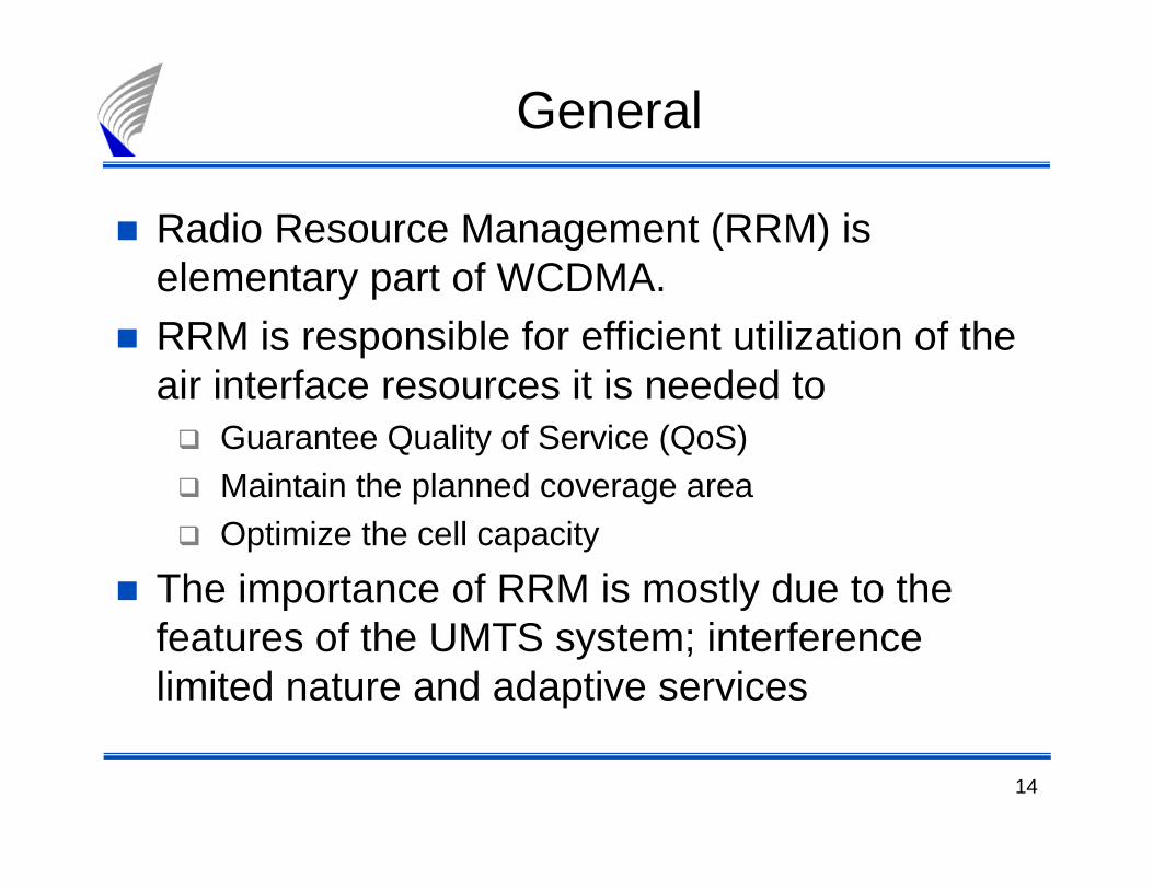
General
� Radio Resource Management (RRM) is elementary part of WCDMA.
� RRM is responsible for efficient utilization of the air interface resources it is needed to � Guarantee Quality of Service (QoS)� Maintain the planned coverage area� Optimize the cell capacity
� The importance of RRM is mostly due to the features of the UMTS system; interference limited nature and adaptive services

15
Introduction to RRM/objectives
Cell coverage Cell capacity
QoS
OPTIMISATION
Objectives of RRM• Ensure planned coverage for each service
• Ensure required connectionquality
• Ensure planned max blocking
• Optimise the usage of systemcapacity resources

16
Introduction to RRM/Functions
Packet Scheduler
Load Control
AdmissionControl
Power Control
HandoverControl

17
Introduction to RRM/Logical model
MS
Node B RNC
• Power Control• Power Control• Load Control
• Power Control • Load Control
• Handover Control • Admission Control
(also in SGSN) • Packet Scheduler
18
RRM algorithms
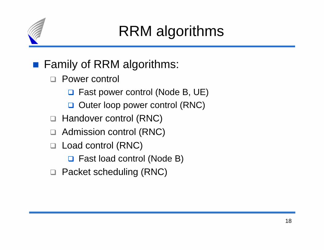
� Family of RRM algorithms:� Power control
� Fast power control (Node B, UE)� Outer loop power control (RNC)
� Handover control (RNC) � Admission control (RNC)� Load control (RNC)
� Fast load control (Node B)
� Packet scheduling (RNC)

19
Power control

20
Power control
� Objectives
� Maintain the link quality in uplink and in downlink by controlling the transmission powers
� Prevents near-far effect� Minimise effects of fast and slow fading� Minimises interference in network
� Accuracy of the power control is important
� No time-frequency separation of users, all use the same bandwidth
� Inaccuracy in power control immediately lifts the n etwork’s interference level, which correspondingly lowers th e capacity
� Due to users mobility the speed of power control is also a critical issue

21
Near-far problem in uplink
� There can large path loss difference between UE1 (c ell centre) and UE2 (cell edge)
� If both UEs are transmitting with the same power th en UE1 will block UE2 (and other cell edge users too)
� Power control will drive transmission powers of UE1 and UE2 to the minimum level that is required to meet QoS
� In Node B received powers from UE1 and UE2 will be the same for same services
UE1
UE2

22
Power control
� Power Control on the common channels ensures that their coverage is sufficient both to set up UE-originating and UE-terminating calls.
� Power Control on the dedicated channels ensures an agreed quality of connection in terms of Block Error Rate ( BLER), while minimizing the impact on other UEs.
� Uplink Power Control increases the maximum number of connections that can be served with the required Qua lity of Service (QoS), while reducing both the interference and the total amount of radiated power in the network.
� Downlink Power Control minimizes the transmission power of the NodeB and compensates for channel fading. Minimizing transmittedpower maximizes the downlink capacity.

23
Power control
� Main power control approaches� Fast power control:
� Aim is to compensate the effect of fast fading� Gain from fast power control is largest for slowly
moving UEs and when fading is flat, i.e. there is multi-path diversity
� Fast power control drives the received power to a target SIR. This value is discussed more closely in connection with dimensioning.
� Outer loop power control� Adjust the target SIR according to service QoS.
24
PC mechanism
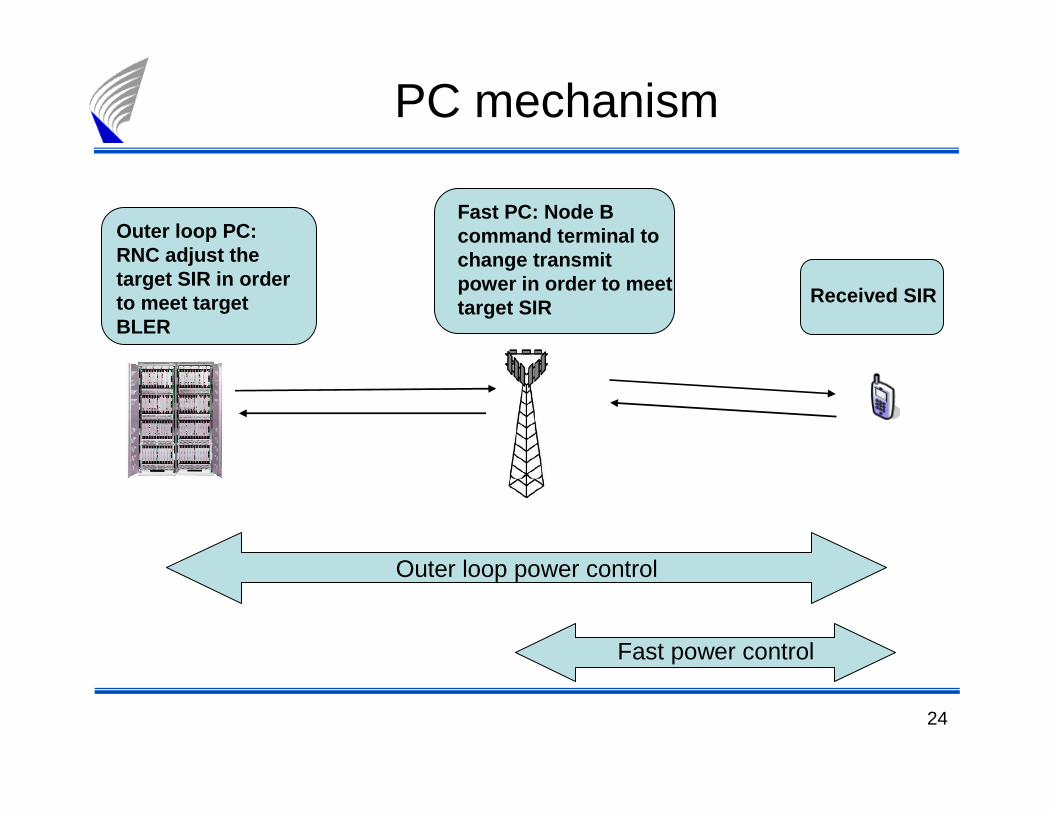
Outer loop PC: RNC adjust the target SIR in order to meet target BLER
Fast PC: Node B command terminal to change transmit power in order to meet target SIR
Received SIR
Outer loop power control
Fast power control
25
Uplink outer loop PC
� The goal is to control the target SIR in order to su stain the wanted QoS with minimum transmit power
� The target BLER is defined with the admission contr ol algorithm
� The uplink algorithm is controlled in RNC � Update frequency from 10 Hz up to 100 Hz� Outer loop power control will raise or lower the ta rget
SIR according to step size, which is defined by rad io network planning.
� The equipments’ performance defines the minimum value for target SIR

26
Downlink outer loop PC
� Implemented in UE to set SIR target on DL traffic channels
� Quality target: BLER of each transport channelas set by RNC
� Admission control determines the value of DL BLER.
� No SIR target change if NodeB power reachesmaximum or network congestion occurs.

27
Transmit Power Control (TPC)
� Ideal fast power control invert the channel� In practice power control accuracy is reduced by
feedback errors, � Better figure, PC headroom etc
Fast fading channel
Transmitted power
Note: It is usual to talk about ‘fast power control ’ when power control is build up to mitigate fast fading. Transmit power control is WCDMA specific term

28
Uplink TPC
� Update rate 1.5 kHz => fast enough to track and compensate fast fading up to x km/h mobile speed
� If received SIR > target SIR in Node B => UE is commanded to decrease its transmit power. Similarly UE is commanded to increase its transmission power ifreceived SIR < target SIR
� Network planning defines the step size. Usual step sizevalues are between 0.5dB and 2dB.
� Soft handover:� UE can receive contradictory PC commands from different
node Bs� UE transmission power will be increased if all node B’s ask for
it and decreased if at least one node B demands it

29
Downlink TPC
� Similar as UL TPC:� UE measures SIR on DL DPCCH during the pilot
period (or use CPICH)� UE maintains the QoS by sending fast power control
commands (TPC bits) requesting power adjustment
� Power offsets can be used in DL in order to improvecontrol reliability. Offsets are network parameters thatcan be set in planning phase

30
TPC characters
� Main interference migitation means in UMTS
� TPC (1500Hz) is able to follow fast fading up to ~50km/h MS speed, afterthat the fading dips are averaged out
� In high MS speeds TPC can have even negative impact
� TPC lowers the required Eb/No, not so much tx-powers directly• Concerns in practise:
•In SHO, DL powers can drift apart due to the inaccurate reception of uplink PC
commands → Degraded SHO performance in case drift prevention not working
•In SHO, DL PC commands cannot be combined in RAKE (becau se theycontain different information). Data bits however can be combined → Worse
reability for PC commands.
=> Can be improved by allocating more power to CCHs
•Building corners in the urban areas
• Average TPC headroom (4dB) must be assumed to pathloss.

31
Handover control

32
Handover types in WCDMA
Inter-system HandoverIntra-system Handover
UMTS -Handover
Intra-frequencyHandover
Soft Hard
UMTS<>GSM
UMTS <> GPRSUMTS <> GPRSetc.
HardSofter
Inter-frequencyHandover
UMTS<>EDGE

33
WCDMA Handover control
Hard HO (HHO)� All the old radio links of an UE are released befor e the new radio links
are established.� Real time bearers: short disconnection in transmission.� Non real time bearers: HHO is lossless.� Shared & common channels used for hard handover (cell reselection)
Soft HO (SHO). � MS always keeps at least one radio link to UTRAN .
� Soft HO: MS is simultaneously controlled by two or more cells belonging to diffetrent BTS of the same RNC or to different RNC.
� Softer HO. MS is controlled by at least two cells under on e BTS.� Dedicated channels (Cell_DCH state) used for SHO
� Handover can be either network or UE initiated � Serving RNC makes the decisions in both cases

34
WCDMA Handover control
Core network
RNC1 RNC2 RNC3 RNC4 BSC
Node B Node B Node B Node B Node B BTS
Iur
Combining (Softer HO)
Soft HandoverSofter Handover
Soft Handover Hard HandoverHard Handover Hard Handover

35
Hard handovers
� Intra & Inter-frequency HHO’s� Usually triggered to maintain mobility� Not recommended in WCDMA unless there is an urgent need,
because� Hard HO increases interference easily, since the re al-time user
is disconnected temporarily and the used power must be re-evalueted
� This decreases the capacity in heavy traffic situations and canworsen the near-far effect
� Absence of Iur (connection between RNC’s) will caus e hard HOs� Compressed mode used in HOs between carriers and sy stems
� In compressed mode UE stop UL transmission for few milliseconds within a radio frame (10ms) in order to enable meas urements of different carriers/systems

36
Inter frequency handover
� IFHO can be used in planning to
� provide coverage (micro ֏ macro cell)
� provide capacity (reduce cell loading)
� 2nd carrier can be enabled on cell basis
� Not so straightforward to perform in UE due to need of compressed mode
� Most Network vendors’ equipment supports IFHO
� IFHO is generally seen as a means of optimisation as the traffic evolves, but can be used also e.g. to provideindoor coverage

37
Soft Handover (SHO)
� SHO helps avoid near-far effect for real-time connection
� For high mobility users shadow fading + (slow) hardhandovers would create near-far situations
� SHO is an essential interference mitigation tool in WCDMA

38
DOWNLINK:� SHO utilises two separate codes in DL (RAKE fingers in UE are
assigned for reception)
� Maximum ratio combining done in UE for the signals
� Produced gain 1-3 dB, however...
�Gain depends on the difference of the signals’ stren gth
�Gain depends on channel conditions and accuracy of the received
channel estimate → In some circumstanses the gain can be lost!
� The more multipath diversity is available the less SHO gain is achived
Soft Handover

39
UPLINK:
� More complex situation than in DL
� During softer HO, same procedure in node B’s RAKE than in DL case
�Produced gain 1-3 dB
�Better performance in terms of strenght differences, since the signals
come from the same source
� During Soft HO, the combining of signals is done in the RNC
�Selection combining performed for baseband signal
�Based on selecting the frame with better FER or BER
�Better frame send to be used in open loop PC (target SIR estimation)
�Gain achieved through more stable UE tx-powers (1-2dB)
→ No actual gain to the radio link
Softer/Soft Handover

40
The cells in a WCDMA RAN are, from UE point of view, divided in different mutual excluding sets defined by 3GPP:
� Active Set� The cells involved in soft handover and measured by the U E
� Monitored Set� The cells only measured by the UE and not part of the Act ive Set. The
monitored set can consist of intra-frequency, Inter-Frequency and Inter-RAT cells
� The cells measured by the UE are the sum of the Active Se t and the Monitored Set.
� The number of Intra-frequency cells in the Monitored Set + the ActiveSet cells is limited by 3GPP to 32.
� The number of Inter-Frequency cells in the Monitored set is limited to 32.
� The number of Inter-RAT cells in the Monitored set is l imited to 32.
Soft Handover

41
Active Set� As UE moves, node Bs are continuously added to and remov ed from the
active set. When added, they are also updated to the neighbor cell list.
� UE measures the monitored set of cells and Handover Control evaluates if
any node B should be added to, removed from or replaced in the active set
� Maximum Active Set Size parameter� is used to determine the maximum allowed number of SHO
connections (varies between 1-5, typical default 3)� Too high value decreases capacity (signalling increases and multiple
connections occur too often)
� Too low value degreases the SHO performance (best candidate cells may
be excluded in some situations)
Soft Handover

42
� The handover measurements for Intra-Frequency HO are based on P-CPICH Ec/Io
� Ec/Io is the received signal code power divided by the total received power. It is calculated from signal before the signal de-spreading operation while Eb/No is calculated after de-spreading.
� Ec/Io can be be determined for the signal ”in the air”
� Eb/No depends on the service (bit rate, CS/PS, receiving end) and Ec/Io is service independent
� The accuracy of the Ec/Io measurements is essential for HO performance
� Depends on filtering lenght and mobile speed
� Filter length for slowly moving & stationary UE’s should be just long enough to avoid Fast Fading errors
� Too long filter length for will cause HO delays to fast moving UE
Soft Handover

43
Event based triggered measurements and reporting
� Basic reporting events 1A, 1B and 1C (Ref. 3GPP)� 1A: Primary CPICH enters the reporting range� 1B: P-CPICH leaves the reporting range� 1C: Non-active P-CPICH becomes better than an active P-
CPICH� 1D: Change of current best cell with new P-CPICH
Handover decision� Done by RNC based on measurements and available
resources
Soft Handover

44
� Picture of events 1A and 1B. Example: The terminal s ends an event 1Areport to the RNC, if the new cell belongs to the m onitored cells list and Active Set is not full. Then new cell is proposed t o be added to the Active Set. If the Active Set is full, the cell is propose d as a replacement of the worst cell in the Active Set (1C)
Soft Handover

45
� Picture of event 1C. Example: The terminal sends an event 1C report to the RNC if the new cell belongs to the monitored ce lls list and Active Set is not full. Then new cell is proposed to be added to the Active Set. If the Active Set is full, theen new cell is proposed as a replacement of the worst cell in the Active Set
Soft Handover
46
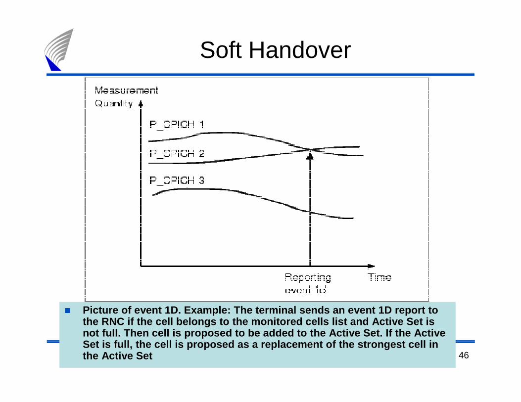
� Picture of event 1D. Example: The terminal sends an event 1D report to the RNC if the cell belongs to the monitored cells list and Active Set is not full. Then cell is proposed to be added to the Active Set. If the Active Set is full, the cell is proposed as a replacement of the strongest cell in the Active Set
Soft Handover

47
� Time-to-trigger
Soft Handover

48
� Inter-Frequency Handover is a hard handover where t he UE is ordered by the network to tune to another frequency.
� This means that there will be small interuptions in the data flow to and from the UE
• When Inter-Frequency HO is considered, first the UE measures the conditions to startCompressed Mode
• Usually Ec/Io of current carrier• Events 2d and 2f defined for
IFHO
• Time to trigger used
Inter-Frequency HO (IFHO)

49
Soft handoverwindow
21
Soft handover margin, which is
defined by radio network
planning
Received signal level inNode B
SHO margin in planning tools
� Some 3G planning tools use one single SHO planning parameter (=SHO margin/SHO gain)
� Default Value varies between 2 and 6 dB
� Value for this parameter should be defined as:
Reporting range1a + Reporting range1b
2Handover margin =

50
HO related topics in network planning
� Network topology: How sites are located relative to each other, how many sectors/site
� Node B antenna radiation patterns� Overlapping patterns => more softer HOs� Antenna tilt => Number of potential Node B’s in Act ive
Set
� Path loss and shadow fading characteristics � The average number of Node B’s that a UE can
synchronise to� HO parameter adjustments is part of the network
optimization

51
Admission and Congestion control

52
Congestion and Admission Control
� Congestion/Load Control’s general responsibility is to remain the network in a stable state and preventoverloading
� Congestion/Load control is in close co-operation withfunctions of admission control and packet schedulerLoad control operates in RNC:
Admissioncontrol
Packet scheduler
Load control
Information of network loading level
Loading status
NRT (Non-Real Timetraffic) load

53
� Admission control� If air interface loading is allowed to increase too much the
coverage of the cell will be reduced below the plan ned value.
� Admission control decides whether to accept the terminal’srequest for new radio access bearer by calculating howmuch interference new bearer would create to the cell in both UL and DL
� Congestion control� Responsible of returning the network back into desi red
target load in case of overload � Target load is set in network planning and overload should
be an exceptional situation
Admission and Congestion Control

54
Load
Interference power
Maximum interference level defined by radio network planning
?
Estimated growth in interference when new UE arrives to the cell
New bearer’sload factor
Maximum load leveldefined by radio network planning
�There are predefined UL and DL thresholds for interference power. Thresholds are set in network planning.
�If either UL or DL threshold is exceeded the RAB is not admitted.
�For decision AC may derive the transmitted bit rate, processing gain, radio link initial qualityparameters, target BER, BLER, Eb/No, SIR target.
Admission Control

55
� In case of congestion the use of resources are scaled do wn to reachnormal loading status
� The priorisation and order of congestion control actions is based on vendor algorithms.
� Actions that can be carried out in order to decrease the load� Deny power control commands received from UE
� Reduce the UL Eb/No target used in UL fast power control
� Reduce the throughput of packet data traffic� Handover to other WCDMA carrier or to GSM
� Decrease bit rates in real time services
� Drop low priority data calls
Congestion control

56
� Determines the available radio resources for NRT radi o bearers� Share the available radio resources between NRT radi o bearers.� Monitor the allocations for NRT radio bearers.� Initiate the switching between common, shared and d edicated
channels when necessary.� Monitor the system loading.� Perform load control actions for the NRT radio beare rs when
necessary.
Packet scheduler

57
� Capacity can be divided between non-controllable and controllable traffic
� Load caused by real time traffic, interference from other cell users and noise together is called non-controllable load
� The part of the available capacity that is not used for non-controllable load can be used for NRT radio bearers on best effort basis (= controllable load).
� PS is implemented for dedicated (DCH) as well as common control transport channels (RACH/FACH).
� PS takes care of filling the controllable capacity with NRT traffic
• The amount of scheduled capacity depends on:• UE and BTS capabilities,• the current load in the cell,• the availability of physical resources.
Packet Scheduler

58
� For dimensioning purposes radio network planning can define packetaccess features per service, e.g.bynext parameters:
� Amount of packet bursts per session� Reading time between bursts� Size of packets� Arrival rate packets� Amount of packets per burst� Number of retransmission
Packet Scheduler

59
Load
InterferenceAdmissioncontrol
Congestioncontrol
Packet Scheduler
Target level for interference
Target level for interference+offset
Threshold
Maximum level
Decrease bit ratesand NRT Bearers
are droppedOverload actions
No actions New RT bearers areadmitted normally
NRT bearers areincreased
NRT load is not increased, but bit rate changes are allowed
No actions No new bearers areadmitted
Preventive load control actions
Decrease bit ratesNo new bearers areadmitted
Control summary