Cellular Mobile Communication Systems Lecture 3
25
TI - 1011 1 Cellular Mobile Communication Systems Lecture 3 Engr. Shahryar Saleem Assistant Professor Department of Telecom Engineering University of Engineering and Technology Taxila TI - 1011
description
Cellular Mobile Communication Systems Lecture 3. Engr. Shahryar Saleem Assistant Professor Department of Telecom Engineering University of Engineering and Technology Taxila TI - 1011. Communication Issues and Radio Propagation. Small scale/Fast fading. - PowerPoint PPT Presentation
Transcript of Cellular Mobile Communication Systems Lecture 3

TI - 1011 1
Cellular Mobile Communication Systems
Lecture 3
Engr. Shahryar SaleemAssistant Professor
Department of Telecom EngineeringUniversity of Engineering and Technology
TaxilaTI - 1011
TI - 1011 2
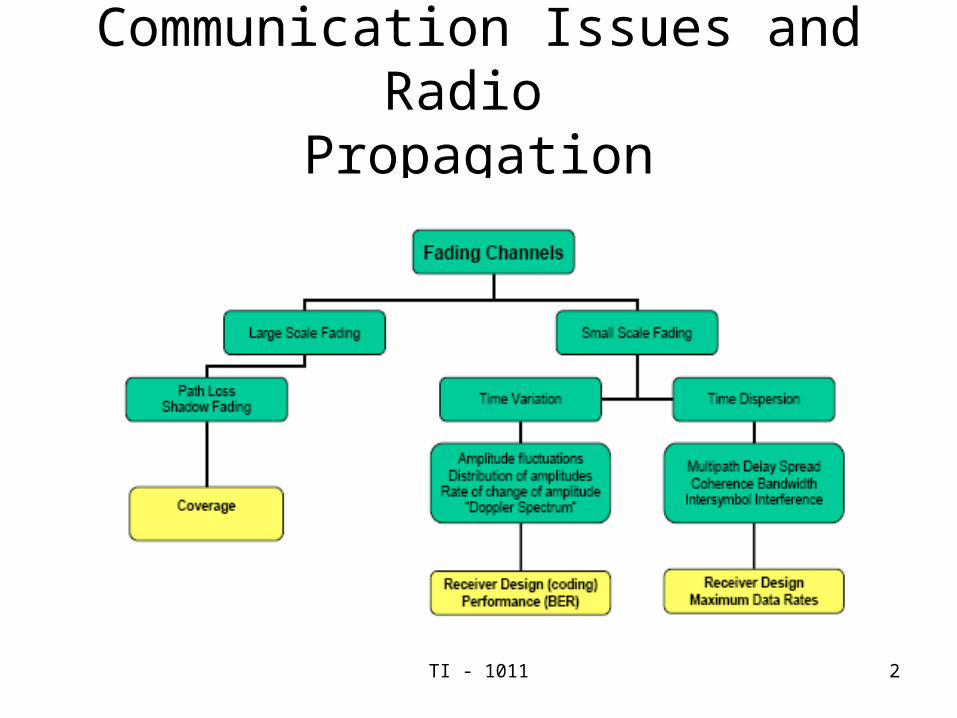
Communication Issues and Radio Propagation

TI - 1011 3
Small scale/Fast fading
• Multipath = several delayed replicas of the signal arriving at the receiver
• Fading = constructive and destructive adding of the signals
• Rapid fluctuation in amplitude with time
• Results in poor signal quality
• Digital communications
– High bit error rates

TI - 1011 4
Constructive and Destructive Fading

TI - 1011 5
Modeling of Multipath Fading
• Fluctuations of the signal amplitude results due to the addition of signals arriving with different phases
• Phase difference because the signals have travelled different distance by different paths
• Phase difference causes rapid fluctuations in the received signal amplitude

TI - 1011 6
Modeling of Multipath Fading
• Fluctuations are modeled as a random variable with a particular distribution
• Generate a histogram of the received signal strength• The density function corresponds to the distribution of
the fluctuating values of the received signal strength• Commonly used distribution for multipath fading is
Rayleigh distribution, whose PDF is given by
• Where r is the random variable corresponding to signal amplitude

TI - 1011 7
Modeling of Multipath Fading
• When a strong LOS signal component also exists• The distribution is found to be Ricean• The PDF of such a distribution is
• K determines how strong the LOS component is with respect to the rest of the multipath
• Small scale fading results in very high bit errors• Techniques used to mitigate the effects of small scale fading
– Error Control coding with interleaving– Diversity schemes– Directional antennas

TI - 1011 8
Small Scale Fading Multipath Delay Spread
• Small scale fading is divided into fading based on– Multipath time delay spread– Doppler spread
• Multipath Delay Spread– In Time Domain
• a transmitted narrow pulse arrives as multiple paths with different strengths and delay
– In Frequency Domain• the response is not flat (suffers from frequency selective
fading)
• Inter Symbol Interference (ISI) caused due to multipath delay spread > the symbol Period

TI - 1011 9
Small Scale Fading Multipath Delay Spread
• ISI results in irreducible errors that are caused in the detected signal
• The effect of ISI can be modeled using a Wideband multipath channel, whose impulse response is:
• Where αi = Rayleigh distributed amplitude of multipath
E{αi}= 2σi => mean local strength,
Ti = multipath arrival time
• Two types of fading based on multipath delay spread
• Flat Fading: where the multipath delay spread < symbol period
• Frequency Selective Fading: where Delay spread > symbol Period

TI - 1011 10
Small Scale Fading/ Time Dispersion Parameters
• In order to compare different multipath channels and to develop general guidelines for wireless systems parameter which quantify the multipath channel are used.
• Mean Excess delay, Rms delay spread and excess delay spread defines the parameters of multipath channel that can be determined form the power delay profile
• Mean excess delay is;
• RMS multipath delay spread is the measure of the data rate that can be supported and is given as;

TI - 1011 11
Small Scale Fading/ Time Dispersion Parameters (cont)
• Where
• Coherence bandwidth is the range of frequencies over which the channel can be considered “flat” i.e. two frequencies of the same signal experience equal amplitude fading.
• Bc= 1/5 σt

TI - 1011 12
Example

TI - 1011 13
Small Scale Fading Doppler Spectrum
• Delay spread and coherence bandwidth describe the time dispersive nature of the channel
• These parameters do not give any information about the time varying nature of the channel caused by either relative motion between the mobile and base station, or movements of objects in the channel
• Doppler spread and coherence time are the parameters which describe the time varying nature of the channel
• Doppler spread BD, is the measure of the spectral broadening caused by the time rate of change of mobile radio channel
• Defined as the range of frequencies over which the received Doppler spectrum is non-zero

TI - 1011 14
Small Scale Fading Doppler Spectrum
• When a sinusoidal tone of frequency fc is transmitted• The received signal spectrum also known as the Doppler spectrum
will have components in the range of fc-fd to fc+fd • fd is the Doppler shift• The amount of spectral broadening depends on fd which is the
function of the relative velocity of the mobile, and the angle θ between the direction of motion of the mobile and the direction of arrival of the scattered waves
• If the based band signal bandwidth is much greater than BD, the effect of the Doppler spread are negligible at the receiver
• This type of channel is a slow fading channel
TI - 1011 15
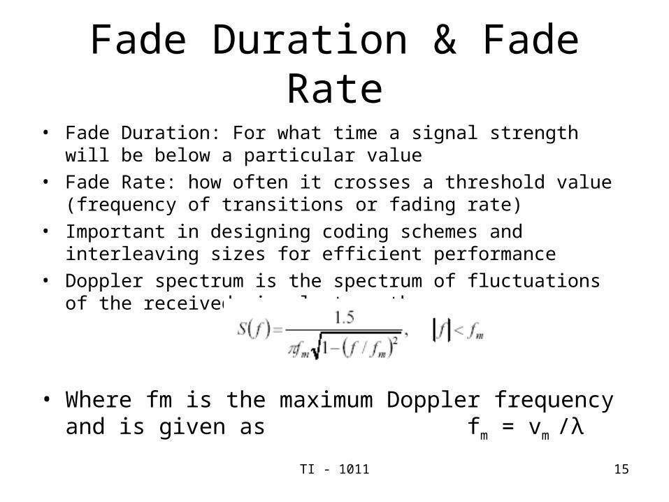
Fade Duration & Fade Rate
• Fade Duration: For what time a signal strength will be below a particular value
• Fade Rate: how often it crosses a threshold value (frequency of transitions or fading rate)
• Important in designing coding schemes and interleaving sizes for efficient performance
• Doppler spectrum is the spectrum of fluctuations of the received signal strengths
• Where fm is the maximum Doppler frequency and is given as fm = vm /λ

TI - 1011 16
Coherence Time
• It is the average time for which the channel can be assumed to be constant
• A good approximation for the coherence time is
• If the symbol duration > Tc, symbol is distorted (Fast Fading)• If the symbol duration < Tc, symbol is not distorted (Slow Fading)
TI - 1011 17
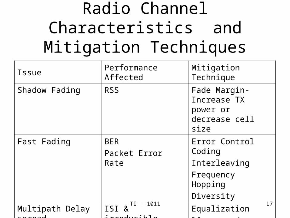
Radio Channel Characteristics and Mitigation Techniques
Issue Performance Affected Mitigation Technique
Shadow Fading RSS Fade Margin- Increase TX power or decrease cell size
Fast Fading BER
Packet Error Rate
Error Control Coding
Interleaving
Frequency Hopping
Diversity
Multipath Delay spread
ISI & irreducible error rates
Equalization
DS- spread spectrum
OFDM
Directional Antennas

TI - 1011 18
Emerging Channel Models
• Position location important for emergency and location-aware applications
• Models developed for communication systems are no longer sufficient to address the performance of Geolocation schemes
• Smart antennas and adaptive antennas needs to know the Angle of Arrival (AOA) of the multipath components

TI - 1011 19
Wideband Channel Models for Geolocation
• Position location applications• Civilian
– Intelligent Transportation System– Public safety (Enhanced 911 or E-911)– Cargo Tracking – Accident reporting
• Military application– Small Unit Operations (SUO) in restrictive RF environment e.g.
buildings, tunnels etc
• Traditional GPS system fails due to lack of sufficient power indoors and the harsh multipath environment

TI - 1011 20
Requirements for Position Based Systems
• For PBS applications detecting the Direct Line of Sight (DLOS) path between TX and RX is extremely important
• DLOS is the straight line connecting the TX and RX even if there are obstacles in between them
• Detecting DLOS is important because the Time of Arrival (TOA) or AOA of the DLOS path corresponds to the distance between the TX and RX
• For telecom application bit error rate is important• For PBS apps, error in detecting the right multipath component can
result in different distance measurements• Thus, PBS using AOA require wide bandwidth to resolve multipath
component and detect the arrival of first path

TI - 1011 21
Classification of channel Profiles for Geolocation Apps
• Channel profiles for Geolocation Apps are divided into three categories
• DDP (Dominant Direct Path)
– In this case traditional GPS receiver (designed for outdoor applications) where multipath components are weaker detects the DLOS path which is the strongest in channel profile (thus accurately detecting the TOA)
• NDDP (Nondominant Direct Path)
– GPS receiver detects a DLOS path but it is not the Dominant path
– For these profiles traditional GPS receivers which is expected to lock to the strongest path
– Detects a TOA that leads to error in position estimation
– The amount of error is the distance associated with the difference between the TOA of the strongest path and the TOA of the DLOS path

TI - 1011 22
Classification of channel Profiles for Geolocation Apps
• Rake Receivers can be used to detect the TOA of the DLOS path for NDDP
• UDP (Undetected Direct Path)
– The GPS system cannot detect the DLOS path
• If dynamic range of receiver is power of strongest signal/power of the weakest detectable path
• UDP can be neglected

TI - 1011 23
Rake Receivers
• Radio receiver designed to counter the effects of multipath
• Uses several “sub- receivers” each delay slightly to tune in to the individual multipath components
• Each component is decoded independently• Later recombined to make the most of the different
transmission x-tics of each transmission path• Results in higher signal - to - noise ratio in multipath
environment than in clean environment

TI - 1011 24
SIMO and MIMO Channel Models
• Spatial wide band channels – Provide the delay-power spectrum as in multipath delay spread – AOA of the multipath components
• SIMO (single input multiple output)– Typical cellular environment
• Mobile transmitters are simple• Base Station
– Complex receiver with smart antennas with M antenna elements– L multipath components arrive at the BS from different MT (l)
with different• Amplitudes (α)• Phases (φ)• Delay (T)• Directions(θ)

TI - 1011 25
MIMO
• Stands for Multiple Input Multiple Output• N mobile antennas• M base station antennas• Spectral efficiency improves• Example• MIMO channel• Experimental results with a 4X4 antenna array system• For MIMO, spectral efficiency of 27.9 b/s/Hz as
compared with spectral efficiencies of 2 b/s/Hz in traditional radio system