CELLU M6 Alliance Medical - lpgsystems.com · 1 In order to respond better to customer requirements...
24
1 In order to respond better to customer requirements and expectations, LPG Systems is continuously researching ways of improving the design and quality of its products. This will explain the few minor differences between your equipment and the item described in this guide. ≥ ATTENTION GU 1601 - Kr Edition A - 02/18 OPERATOR’S MANUAL Registered trademark Congratulations on the purchase of your CELLU M6 ® Alliance Medical. This model represents the fruits of numerous years of experience in the design and production of cutaneous tissue treatment systems. You will experience fully the technical perfection and reliability of LPG Systems, which is the leader in this sector. With the aim to continuously provide satisfaction, your device is equipped with a specific software devised to ensure connection with the LPG dedicated server. The data collected through this software will allow LPG to give you better services in respect of support and maintenance. This operator’s manual contains the operating description, basic maintenance instructions to be performed periodically and the safety instructions. Your device is intended for use in the treatment of connective tissue. It should be used only by a professional who has attended the manufacturer’s training provided by LPG Systems or an approved provider, if you live outside of France. If you have any doubts whatsoever concerning the operation or maintenance of your equipment, please do not hesitate to contact LPG via the Customer Service Department of your distributor. +33 (0)4 75 78 69 00 Please read the complete manual carefully before using your equipement. © Copyright 2016. LPG, CELLU M6 and Alliance are registered trademarks of LPG. Reproduction, even in part, is strictly prohibited. CELLU M6 ® Alliance Medical
Transcript of CELLU M6 Alliance Medical - lpgsystems.com · 1 In order to respond better to customer requirements...

1
In order to respond better to customer requirements and expectations, LPG Systems is continuously researching ways of improving the design and quality of its products. This will explain the few minor differences between your equipment and the item described in this guide.
≥ A T T E N T I O N
GU 1601 - KrEdition A - 02/18
OPERATOR’S MANUAL
Registered trademark
Congratulations on the purchase of your CELLU M6® Alliance Medical. This model
represents the fruits of numerous years of experience in the design and production
of cutaneous tissue treatment systems. You will experience fully the technical
perfection and reliability of LPG Systems, which is the leader in this sector.
With the aim to continuously provide satisfaction, your device is equipped with
a specific software devised to ensure connection with the LPG dedicated server.
The data collected through this software will allow LPG to give you better services
in respect of support and maintenance.
This operator’s manual contains the operating description, basic maintenance
instructions to be performed periodically and the safety instructions.
Your device is intended for use in the treatment of connective tissue. It should be
used only by a professional who has attended the manufacturer’s training provided
by LPG Systems or an approved provider, if you live outside of France.
If you have any doubts whatsoever concerning the operation or maintenance of
your equipment, please do not hesitate to contact LPG via the Customer Service
Department of your distributor.
+33 (0)4 75 78 69 00
Please read the complete manual carefullybefore using your equipement.
© Copyright 2016. LPG, CELLU M6 and Alliance are registered trademarks of LPG. Reproduction, even in part, is strictly prohibited.
CELLU M6® Alliance Medical

2 3
Unpackaging instructions to be retained.
≥ A T T E N T I O N
> PACKAGE CONTENTS
> One CELLU M6® Alliance Medical device
> One Alliance 80 head
> One Alliance 50 head
> One TR30 head
> One set of micro-nozzles and micro-heads
> One Ergolift® head
> Two Ergolift® chamber (Lift20 and Lift10)
> One electrical power cord
> One unpackaging instructions and quick installation guide
> One marketing set
Pack body
Pack face
Pack therapeutic
Pack aesthetical medicine
Pack spa
Alliance 80 √
Alliance 50 √ √ √
TR30 √ √ √
Micro-nozzleset micro-heads
√ √
Ergolift √ √ √
Ergolift chamber (Lift 10, Lift 20)
√ √ √
Unpackaging instructions and quick installation
guide
√ √ √ √ √
Cord √ √ √ √ √
Marketing set √ √ √ √ √
Depending on the version you have, (see serial number on the nameplate), some protocols are not activated and their accessories are not provided. Accordingly, the paragraphs describing them do not concern this version (see table below). In any doubt about the operation of your unit or to evolve into a complete model, please contact the Customer Service of LPG Systems or your distributor.
Liste of accessories provided with your device :

54
The manufacturer reserves the right to amend the product technical specifications without prior notice. Any reproduction – even in part – is prohibited. All the illustrations in this operator’s manual are non-binding.
≥ A T T E N T I O N
> DESCRIPTION OF THE DEVICE
DE
SC
RIP
TIO
N O
F T
HE
DE
VIC
E
1 > SOMMAIRE
INTENTED USE
The CELU M6® Alliance Medical device is intended for therapeutic use. It can be used to :
1. Reduce secondary lymphedema of the arm after a mastectomy
2. Improve secondary lymphedema
3. Improve lymphatic circulation in the treated area
4. Relief of minor muscle aches and pains
5. Relieve muscle spasms
6. Temporary improvement in local blood circulation
7. Temporary relief of the minor muscular pain associated with DOMS (Delayed Onset Muscle Soreness)
8. Improves local circulation during burn rehabilitation
9. Reduce the appearance of cellulite and the circumference of treated areas
10. Temporarily improve lymphatic circulation and local blood circulation to improve skin trophicity in the treated areas
11. Improvement of skin quality, scars, fibrosis
12. Improvement of skin aging (wrinkles, fine lines, skin sagging, fat infiltration, firmness, elasticity, complexion, eye bags)
13. Stimulation of fibroblasts (collagen, elastin, hyaluronic acid synthesis)
The machine can be used in hospitals and rehabilitation clinics by specialists and physical therapists. It can be used on patients of any age, any weight, any sex. It is an independent device that cannot be combined with other machines. It should only be used by professionals who have been specially trained by LPG Systems how to use it and is not suitable for use at home.
OPERATING PRINCIPES :
The operating principles of the medical device CELLU M6® Alliance Medical consist of a suction force coupled with movements of rolls / valves, performed with treatment heads. These heads are placed on the healthy skin of the patient and then moved across the area to be treated by the professional who has been trained by LPG Systems.
1. DESCRIPTION OF THE DEVICE . . . . . . . . . . . . . . . . . . . 5
2. DESCRIPTION OF THE CONTROLS . . . . . . . . . . . . . . . . . 7
3. PRECAUTION FOR USE . . . . . . . . . . . . . . . . . . . . . . 10
4. MAINTENANCE . . . . . . . . . . . . . . . . . . . . . . . . . . 14
5. TROUBLESHOOTING . . . . . . . . . . . . . . . . . . . . . . . 22
6. TECHNICAL SPECIFICATIONS . . . . . . . . . . . . . . . . . . 23
7. TREATMENT HEADS . . . . . . . . . . . . . . . . . . . . . . . 24
8. ENDERMOWEAR . . . . . . . . . . . . . . . . . . . . . . . . . . 39
9. GENERAL WARRANTY CONDITIONS . . . . . . . . . . . . . . . 40
10.APPENDIX: ELECTROMAGNETIC COMPATIBILITY . . . . . . . . 44
76
For detailed instructions on using the touch interface, refer to the touch interface operating manual received during training and available from customer service.
≥ A T T E N T I O N
The unit can only operate if it is connected to the mains by its power cord and provided the ON switch has been actuated and the green voltage light is on. After switching on the unit, please wait a few seconds for the screen to display information.
≥ A T T E N T I O N
> ACCES TO FILTER
DE
SC
RIP
TIO
N O
F T
HE
CO
NT
RO
LS
2
> CONTROL SCREEN
DE
SC
RIP
TIO
N O
F T
HE
DE
VIC
E
1 > THE CELLU M6® ALLIANCE MEDICAL DEVICE
LEFT HOSE FILTER
RIGHT HOSE FILTER
ACCES TO FILTERS
The filters are accessible via the back of the unit.
CASTER LOCKING MECHANISM
LEFT HOSE
FORWARD-FACING TOUCH SCREEN
HEAD HOLDER
IDENTIFICATION PLATE
FILTER ACCESS DOOR
POWER SWITCH, SOCKET, AND POWER INDICATION
Before use, ensure that the power cord is completely unwound. POWER INDICATOR
TOUCH SCREEN
ACCES USB PORT
RIGHT HOSE
HEAD HOLDER
HEAD STORAGE DRAWER
HEAD STORAGE TRAY
CASTERS

98
In cases where the unit has not been moved for a long time, it is possible that marks may form on the ground where the casters are. This phenomenon is the result of a chemical reaction between the components of some floorings and those of the wheels of the CELLU M6® Alliance.
≥ A T T E N T I O N
> ADAPTATER ERGOLIFT HEAD
> CASTERS
2 > ALLIANCE 80 HEAD2
> ALLIANCE 50 AND TR30 HEADS
DE
SC
RIP
TIO
N O
F T
HE
CO
NT
RO
LS
DE
SC
RIP
TIO
N O
F T
HE
CO
NT
RO
LS
SELECTION BUTTON TOR TREATMENT TYPE
POWER INCREASE BUTTON
POWER DECREASE BUTTON
ON/OFF BUTTON
HOSE CONNECTION
ERGOLIFT CHAMBER CONNECTION
They can be connected and disconnected by a simple push-pull action.
UNLOCKED TO LOCK LOCKED
The CELLU M6® Alliance Medical is equipped with locking casters. Please follow the procedure indicated below to lock or unlock the casters :
PARAMETER SETTING BUTTONS
EMBELLISHER FLAP
BRIGHT LEDS
ADJUSTEMENT SLIDER POSITION ROLLER AND FLAP
MOTORIZED ROLLER AND FLAP
PARAMETER SETTING BUTTONS
EMBELLISHER FLAP
MOTORIZED ROLLER AND FLAP
ADJUSTEMENT SLIDER POSITION ROLLER
AND FLAP
ALLIANCE 50 TR 30
SEALING FLAP
MOTORIZED ROLLER
ADJUSTEMENT SLIDER POSITION ROLLER

1 01 0 1 1
Europe VII-H05VVF3G1,50-C19; Italy I/3/16-H05VVF3G1,50-C19; Switzerland 23G-H05VVF3G1.50-C19; UK BS13/13-H05VVF3G1,50-C19; Japan 498GJ-VCTF3X2.00-C19; USA, Canada, Mexico N5/15-SJT3X14AWG-C19 (connect to Hospital grade receptacle in hospital environnement).
> IMPORTANT SAFETY INFORMATION
PR
EC
AU
TIO
NS
FO
R U
SE
3
PR
EC
AU
TIO
NS
FO
R U
SE
3
> PRECAUTIONS FOR USE
> IMPORTANT SAFETY INFORMATION
> WARNING
All safety precautions must be observed whilst using electrical equipment. Please read all safety notices and precautions prior to use of the equipment.
• Never touch the patient and the device’s unprotected cables or connectors simultaneously.
• Never use the adapter as a treatment head or allow it to come into direct contact with the skin.
• Only use treatment heads supplied with your unit or recommended by LPG.
• Do not use the treatment heads directly on the skin. Wear the treatment suit provided by LPG Systems, ENDERMOWEAR.
• LPG Systems will not be liable for any inappropriate use of the equipment.
• Improper use of the device can cause tissue damage or pain.
• The operator must be particularly attentive to the sensations felt by the person undergoing treatment.
• The operator must ensure that the parameters (intensity, sequentiality, differential...) are always adapted to the tissue being treated.
• Do not lean, rest, or sit on the unit.• When crossing a threshold or step, we
recommend moving the unit carefully by firmly holding the central arm monitor stand to avoid the risk of tipping.
• Do not use the USB connection during treatment.• Do not operate the unit in unsuitable
environmental conditions (see technical specifications).
• The power plug is used as disconnect device. The disconnection of the unit is disconnecting the power plug.
• Please position your device so that the mains unit is always accessible.
• Do not touch the patient and the hose connectors simultaneous
• Do not use the treatment heads in contact with vegetable oils
≥ A T T E N T I O N
• Always disconnect the equipment from the electrical supply outlet after use and before cleaning and maintenance.
• Check that the supply voltage of the unit indicated on the data plate complies with the mains voltage.
• The unit must be connected by the power cord1 supplied to a grounded outlet in accordance with current electrical standards. Electrical adapters must not be used with this equipment.
• Ensure that the unit is connected to a system with a differential protection against DC and AC.
DANGER - TO MINIMISE THE RISK OF ELECTRICAL SHOCK:
• TO MINIMISE THE RISK OF BURNS, FIRE, ELECTRICAL SHOCK OR INJURY:
• The equipment must not be left unattended whilst connected to the electrical supply.
• Disconnect the unit from the electrical supply if it is not going to be used for a long period.
• Special attention is required whilst using the equipment with, or in the proximity of children or disabled persons.
• Never use the unit for purposes other than those recommended by LPG Systems. Only use the treatment heads supplied with your unit or recommended by LPG.
• Never use the equipment if: The electrical power cord or outlet is damaged. The equipment does not function correctly. The equipment is damaged or has fallen or been dropped. The equipment has been exposed to excessive humidity.
• Do not move the unit by pulling the electrical power cord.
• Fully unwind the electrical power cord and keep it away from warm surfaces.
• Never use the equipment if the ventilation ports are obstructed. Ensure that the ventilation ports are kept clear of dust or other contaminants.
• Do not allow solid debris, liquid or other foreign bodies to fall or be sucked into the unit, as these could cause damage.
• Never use the equipment on a dusty, uneven floor, or in a moist atmosphere.
• Never use the equipment in the presence of aerosols or oxygen.
• Before disconnecting the unit from the electrical supply, set all controls to the ‘off’ position and unplug the unit. The disconnection of the unit is disconnecting the power outlet.
• It is prohibited to modify this equipment without prior authorisation from the manufacturer.
• It is prohibited to use components or spare parts non recommended by LPG.
• Return the device to LPG Systems Service Center for examination and repair.
ATTENTION: KEEP THESE INSTRUCTIONS.Your device should be used on healthy skin. It is important to read and respect the following precautions and contraindications before using your device.

1 2 1 3
This unit contains programs to help the operator obtain the best anticipated results for each case undergoing treatment. Under no circumstances may these programs be construed as a guarantee of successful treatment, which varies, depending on the morphology, physiology and eating behavior of each patient.
≥ A T T E N T I O N
> ELECTROMAGNETIC COMPATIBILITY > CONTRA-INDICATIONS3
PR
EC
AU
TIO
NS
FO
R U
SE
PR
EC
AU
TIO
NS
FO
R U
SE
3• Do not treat open wounds, the eyes,
intra-cavity areas, mucous membranes, the genitals or breasts.
• This device is not recommended for pregnant women. In the event of pregnancy, do not treat the lumbar-abdominal region. Consult with a doctor with regard to this treatment.
• Do not treat a patient with an infectious disease, a growing tumour, a phlebitis, a wound, or an infected area.
• Do not treat a patient with skin cancer, a visible tumor, or other cancerous lesions. Consult with a doctor in cases where the patient has a case history of tumours or is in remission.
• Do not treat inflamatory areas or scars without medical advice and LPG technical training for the affected areas.
• Do not treat people with circulatory problems without first consulting their doctor and without training in LPG technology for the affected areas.
• Do not treat a patient with an unexplained and persistent pain without medical advice and without training in LPG technology for the affected areas.
• Do not treat a patient after an invasive medical treatment without medical advice or surgeon who carried out the treatment and without training in LPG technology for the affected areas.
• To avoid bruising, exercise caution when determining a patient’s level of sensitivity and avoid use on patients taking anticoagulant drugs.
• Stop treatment immediately if the patient experiences pain and consult a doctor.
• This device should not be used on all dermatoses, skin rashes, herpes, inflammatory or infectious acne or vitiligo.
• Because of the risk of interference, it is important that the professional ensures the patient is not equipped with a personal medical device such as a pacemaker. If this is the case, the professional should obtain details about the device in question to ensure that any interference will not affect the correct use of the equipment.
• As this list is not exhaustive, always seek out medical advice in the event of doubt.
• For a more detailed list of indications and against indications, refer to training manuals.
• Your CELLU M6® Alliance Medical device requires special care concerning the EMC, it must be installed and service according to the information provided in this user guide.
• Portable and mobile RF communication devices must not be used near your device, they can cause undesired operation.
• The use of other treatment heads than those provided by LPG may result in increased emissions or decreased immunity of the device.
• Your CELLU M6® Alliance Medical device should not be used adjacent to or stacked with other medical devices.
• Interference may occur near equipment marked with the following symbol:
For more information concerning the electromagnetic compatibility, refer to appedix « Electromagnetic compatibilty »

1 4 1 5
The identification rating plate is located on the underside, at the back of the unit. Identification rating plates may vary. The approved one is one on your machine.
Proscribe aggressive products such as acetone, trichlorethylene or alcohol at 90°.
≥ ≥A T T E N T I O N A T T E N T I O N
MA
INT
EN
AN
CE
4
MA
INT
EN
AN
CE
4 > IDENTIFICATION RATING PLATE > CLEANING THE UNIT
This icon indicates that the unit was sold after August 13, 2006. In conformity with the 2002/96/CE directive, it cannot be thrown away with standard household waste but must be disposed of by means of recycling. When your device reaches the end of its useful life, it must be brought to an appropriate recycling center or returned to your dealer. By doing so, you help the environment by contributing to the conservation of natural resources and the protection of human health.
This icon indicates that some specific warnings or precautions associated with this device are not on the label.
This symbol means you must consult the accompanying documents before using your device.
This symbol indicates the name and address of the manufacturer.
This symbol means that your device has type BF applied parts which come into contact with the patient. These parts are electrically isolated from all of the device’s other parts. These applied parts are: the treatment heads.
This symbol means store the device somewhere protected from inclement weather.
This symbol indicates temperature limits.
This symbol indicates the weight of the device
This symbol indicates relative humidity limits.
This symbol means « Do not push »
This symbol means « danger: High Voltage »
This symbol means
« use under prescription » (US only).
This symbol indicates the year of the manufacturing
This symbol indicates fragile, handle with care
This symbol indicates keep it vertical
This symbol indicates not reverse
This symbol indicates athospheric pressure limits.
Your unit is identified by a serial number shown on the rating plate. The rating plate also shows the permitted supply voltage for the unit. If you need to contact LPG Systems because of a technical problem, please indicate the serial number of your CELLU M6® Alliance Medical. This serial number provides information on the year and month of manufacture of your unit.
The letter indicates the year the device was manufactured. Z=2009, A=2010, B=2011, etc.
The two digits indicate the production month: 01=January; 02=February; 03=March; etc.
serial number
voltage, frenquency and power
It is recommended that you clean your unit as often as possible, not only for reasons of hygiene and aesthetics but also because cleaning the unit will help keep it in a good state of repair and extend its useful life.
Using a vacuum cleaner with a fine nozzle, clean the following sections:
• Interior of the head storage drawer. • Interior of the head storage tray. • Interior of the filter access door.
Using a moist sponge, clean the following sections:
• All the external hoods. • Hoses. • The electrical power cord.
Using a cloth soaked with a small amount of alcohol-free domestic cleaning product, clean the following sections:
• Control screen and control panel. • Interior of the head storage drawer. • Interior of the head storage tray. • Interior of the filter access door.
Using an antistatic cloth soaked or wipes, clean:
• The touch screen.
The maintenance of the treatement heads should be performed before the first use, see chapter «treatment heads».

1 71 6≥ A T T E N T I O N
MA
INT
EN
AN
CE
4
MA
INT
EN
AN
CE
4
FILTER METER
FIG. 6
1. Open the filter access door. (Fig 1)
2-3. Unscrew and remove the filter cartridges and replace them with new ones. (Fig 2 et Fig 3)
4. Remove the filter foam and replace it with a new one. (Fig 4 et Fig 5)
Remember to purchase new filter cartridges from the LPG Systems Customer Service Department so you always have a spare.
FIG. 1 FIG. 2
FIG. 3
5. Once the filter cartridge is replaced, the filter meter should be reset by pressing the icon indicated: (Fig 6)
> REPLACING THE FILTER CARTRIDGES AND FOAM
FIG. 5
FIG. 4
FIG. 1
FIG. 3
FIG. 2
FIG. 4 FIG. 5
The device must never be used without a filter. If no filter is fitted, the device must be switched off.
Your device contains two filter cartridges and one filter foam. These components guarantee the efficiency of your unit and prolongs its useful life.
The ‘filter change’ screen indicates which filter requires changing (Fig. 5).
Ensure that they are changed as soon as the command screen displays one of these messages (Fig 1-2) :
Icon indicating a filter change is required (Fig. 2).
Access the ‘filter change’ menu as follows : Select the ‘maintenance’ menu by pressing the icon indicated (Fig. 3). Select the ‘filter’ menu by pressing the icon indicated (Fig. 4).
Replace the filter cartridges as follows :
> REPLACING THE FILTER CARTRIDGES AND FOAM
FILTER TO CHANGE
PRESS THIS ICONPRESS THIS ICON
CHANGE THE FILTERS

1 8 1 9
> CONNECTING / DISCONNECTING THE MOTORIZED TREATMENT HEADS
MA
INT
EN
AN
CE
4
MA
INT
EN
AN
CE
4
FIG. 2
FIG. 4 FIG. 5
To connect the heads to the hose, follow the procedure below.Position the locking ring in the locked position (Fig.1)Position the end of the hose so that the hose key is lined-up with the key slot of the treatment head connection (Fig.2)
Push the hose into the treatment head connection until it cliks into place.
FIG. 3
> CONNECTING / DISCONNECTING THE ADAPTER
ADAPTER CONNECTION MICRO-HEADS AND MICRO-NOZZLES CONNEXION
To connect or disconnect the hose adapter, follow the procedures described on the chapter 4.4 « Connecting /Disconnecting the motorized treatment heads ».
The connection is made with a simple push/pull movement.
HOSE CONNECTION
TREATMENT HEADCONNECTION
FIG. 1
LOCKING RING
ORNEMENTAL RING
LOCKEDPOSITION HOSE KEY
KEYSLOT
To disconnect the heads to the hose, follow the procedure below.
Position the locking ring in the unlocked position (Fig.3)Pull the locking ring towards the hose (Fig.4)Carefully remove the hose by pulling it by the white ring (Fig.5)
UNLOCKEDPOSITION
Only the micro-heads and the micro-nozzles can be connected to the adapter.The connexion is made with a simple push/pull movement.
UNLOCKED LOCKED

2 12 02 0
> INSTRUCTION TO REMOVE USB PROTECTIVE COVER
MA
INT
EN
AN
CE
4 > MAINTENANCE LOG SHEET
Replacement of filter cartridges: To be done when the warning message.Replacement of sealing flap: To be done when the flaps no longer treat the skin properly. They should be replaced after every 100 hours of use.
DATE N° OF HOURS OPERATION PERFORMED
MA
INT
EN
AN
CE
4
> REPLACING THE POWER CORD
If the power cord of your device is damaged, please contact LPG Systems Customer Service for a replacement.
LPG Systems Customer Service: +33(0)4 75 78 69 00
Remove the access cover to the USB port by using the appropiate tool.

2 2 2 3
TE
CH
NIC
AL
SP
EC
IFIC
AT
ION
S
6 > WHAT IF I’VE A PROBLEM ?
TR
OU
BL
ES
HO
OT
ING
5 > TECHNICAL SPECIFICATIONS
Dimensions LxWxH: . . . . . . . . . . . . . . . . . . . . . . . . . . . . . . . . . . . . . . . . . . . . . . . . . 61x70x140 cmNet weight: . . . . . . . . . . . . . . . . . . . . . . . . . . . . . . . . . . . . . . . . . . . . . . . . . . . . . . . . . . . . . . . 80,5 kgMaximum set depression: . . . . . . . . . . . . . . . . . . . . . . . . . . . . . . . . . . . . . . . . .69 kPa (690 mbar)Cooling: . . . . . . . . . . . . . . . . . . . . . . . . . . . by mechanical ventilation incorporated in the pumpProtection index: . . . . . . . . . . . . . . . . . . . . . . . . . . . . . . . . . . . . . . . . . . . . . . . . . . . . . . . . . . . . IP 20Electrical protection class: . . . . . . . . . . . . . . . . . . . . . . . . . . . . . . . . . . . . . . . . . . . . . . . . . . . . . . . 1Wifi: . . . . . . . . . . . . . . . . . . . . . . . . . . . . . . . . . . . . . . . . . . . . . . . . . . . . . . . . . . . . . . . 2,4Ghz b/g/nElectrical features: . . . . . . . . . . . . . . . . . . . . . . . . . . . . . . . . . . . . . . . . . . . . 100-240V 50Hz 730W . . . . . . . . . . . . . . . . . . . . . . . . . . . . . . . . . . . . . . . . . . . . . . . . . . . . . . . . . . . . . 100-230V 60Hz 730W
Operating environmental features:Ambient temperature: . . . . . . . . . . . . . . . . . . . . . . . . . . . . . . . . . . + 10 à + 30°C for normal use.Ambient relative humidity: . . . . . . . . . . . . . . . . . . . . . . . . . . . . . 30 à 75% without condensation.Atmospheric pressure: . . . . . . . . . . . . 800 à 1050 hPa (For use in a normally ventilated room)Max altitude: . . . . . . . . . . . . . . . . . . . . . . . . . . . . . . . . . . . . . . . . . . . . . . . . . . . . . . . . . . . . . 2500m
Environmental characteristics of transport and storage:Temperature: . . . . . . . . . . . . . . . . . . . . . . . . . . . . . . . . . . . . . . . . . . . . . . . . . . . . . -20°C to +70°CAmbient relative humidity: . . . . . . . . . . . . . . . . . . . . . . . . . . . . 10 to 90% without condensationAtmospheric pressure : . . . . . . . . . . . 800 to1050 hPa (For use in a normally ventilated room)
Your device is equipped with patented treatment heads (applied parts type of BF).
The CELLU M6® Alliance Medical device is marked as a medical device by virtue of Annex II of regulation 93/42/EEC (applicable standards IEC 60601-1 Ed3 and related standards).
If your unit is not working properly, proceed with the following checks before calling Customer Services:
• Is the unit properly connected to a mains plug? • Is the mains plug live? • Is the ON switch lit up? • Are the filter cartridges clean and correctly placed? • Are the hoses properly connected? • Are the treatment heads properly connected ? • Is the connected treatment head connected corresponds to that shown on the screen?
Once these checks have been carried out and if the malfunction persists, please contact Customer Services of LPG Systems or the nearest authorized dealer, indicating the model of your unit and its serial number.
Service Client de LPG Systems :+33 (0)4 75 78 69 00

2 4 2 5
TÊ
TE
S D
E T
RA
ITE
ME
NT
7
TR
EA
TM
EN
T H
EA
DS
7 > INDEX
CELLU M6® Alliance MedicalDESCRIPTION OF ALLIANCE 80 HEAD. . . . . . . . . . . . . . . . . . . . . . . . . . . . . . . . . . . . . . . 26
DESCRIPTION OF ALLIANCE 50 HEAD. . . . . . . . . . . . . . . . . . . . . . . . . . . . . . . . . . . . . . . 28
DESCRIPTION OF TR30 HEAD . . . . . . . . . . . . . . . . . . . . . . . . . . . . . . . . . . . . . . . . . . . . . 30
DESCRIPTION OF ERGOLIFT HEAD . . . . . . . . . . . . . . . . . . . . . . . . . . . . . . . . . . . . . . . . . 31
DESCRIPTION OF MICRO-HEADS AND MICRO-NOZZLES . . . . . . . . . . . . . . . . . . . . . . . . 32
MAINTENANCE . . . . . . . . . . . . . . . . . . . . . . . . . . . . . . . . . . . . . . . . . . . . . . . . . . . . . . . . . 33
TREATMENT HEADS
Registered trademark

2 6 2 7
TR
EA
TM
EN
T H
EA
DS
7
TR
EA
TM
EN
T H
EA
DS
7 > DESCRIPTION OF THE ALLIANCE 80 HEAD > DESCRIPTION OF THE ALLIANCE 80 HEAD
BRIGHT LEDS
ADJUSTMENT OF ROLLER AND FLAP POSITION
Alliance head 80 has an adjustable stop with 2 positions for adjusting the distance between the motorized roller and of the damper.
When the cursor is in the horizontal position, the maximum mobility of the rollers is ensured.
When the cursor is in the vertical position, the minimum mobility of the rollers is ensured.
START / STOP BUTTONThe Alliance 80 head can be used to the Endermologie body treatment.
PARAMETER SETTING BUTTONS
EMBELLISHER FLAP
NAVIGATION BUTTONS
ADJUSTEMENT SLIDER
POSITION ROLLER AND FLAP
EMBELLISHER FLAP
MOTORIZED FLAP
MOTORIZED ROLLER
MINIMUM SPACING POSITION
MAXIMAL SPACING
POSITION
To change the adjustment slider turns it into the holding down to the desired position, as shown in the photo below:

2 92 8
7
TÊ
TE
S D
E T
RA
ITE
ME
NT
7 > DESCRIPTION OF ALLIANCE 50 HEAD > DESCRIPTION OF ALLIANCE 50 HEAD
TÊ
TE
S D
E T
RA
ITE
ME
NT
The Alliance 50 head can be used to the therapeutic treatment (fibrosis, edema, inflammation …).
PARAMETER SETTING BUTTONS
NAVIGATION BUTTONS
START / STOP BUTTON
EMBELLISHER FLAP
MOTORIZED FLAP
ADJUSTEMENT SLIDER POSITION ROLLER AND FLAP
MOTORIZED ROLLER
MOTORIZED FLAP
TREATMENT CHAMBER
ADJUSTMENT OF ROLLER AND FLAP POSITION
Alliance head 80 has an adjustable stop with 2 positions for adjusting the distance between the motorized roller and of the damper.
When the cursor is in the horizontal position, the maximum mobility of the rollers is ensured.
When the cursor is in the vertical position, the minimum mobility of the rollers is ensured.
MINIMUM SPACING POSITION
MAXIMAL SPACING
POSITION
To change the adjustment slider turns it into the holding down to the desired position, as shown in the photo below:

3 13 0 3 1
TR
EA
TM
EN
T H
EA
DS
7
TR
EA
TM
EN
T H
EA
DS
7 > DESCRIPTION OF THE ERGOLIFT HEAD
> DESCRIPTION OF ERGOLIFT CHAMBERS
> DESCRIPTION OF TR30 HEAD
Lift 20 Treatment
chamber with removable flap
Only the LIFT 20 and LIFT 10 can be connected to the Ergolift head. Thay can be connected and disconnected by a simple push-pull action.
Lift 10 Treatment
chamber with removable flap
SELECTION BUTTON FOR TREATMENT TYPE
POWER INCREASE BUTTON
POWER DECREASE BUTTON
ON / OFF BUTTON
HOSE CONNECTION
ERGOLIFT CHAMBER CONNECTION
They can be connected and disconnected by a simple
push-pull action.
PARAMETER SETTING BUTTONS
ROLLER LOCKING MECHANISM
START / STOP BUTTON
SEALING FLAP
MOTORIZED ROLLERS
The Egolift chamber Lift 20 can be used to the treatment of large areas with fine tissues, and sensible areas. The Ergolift chamber Lift 10 can be used to the treatment to tight areas, eyes and lip contour, hands and figers.

3 33 2
TR
EA
TM
EN
T H
EA
DS
7 > DESCRIPTION OF MICRO-HEADS AND MICRO-NOZZLES
TR
EA
TM
EN
T H
EA
DS
7 > MAINTENANCE
For reasons of hygiene, the maintenance of the treatment heads should be performed after each use, using antiseptic wipes impregnated with a bactericidal and fungicidal solution.Special attention must be given to the maintenance of the parts that are in contact with the patient.
THE ALLIANCE 80 HEAD 1. Remove the sealing flaps (2 up flaps and 1 down flap) as showed in the pictures below
(fig 1 à 4). 2. Thoroughly rub for at least one minute with the wipes as describe here below.: a) Flaps and their housing (fig 5 to 7). b) The casing on both sides of the rollers (turn the head over, rotate the rollers
manually to clean the entire surface) (fig. 8). c) The motorized flap (Don’t mobilize the motorized flap) (fig 9 & 10). d) Le sabot3. Reattach the sealing flaps4. Maintain the storage drawer using LPG wipes, then place the head in it.
NOZZLE CONNECTIVE
TR 15 HEAD
MICRO-NOZZLES
MICRO-HEADS
Fig 1 Fig 2 Fig 3 Fig 4
Fig 5 Fig 6 Fig 7 Fig 8
Fig 9 Fig 10
3 53 4
> MAINTENANCE 77 > MAINTENANCE
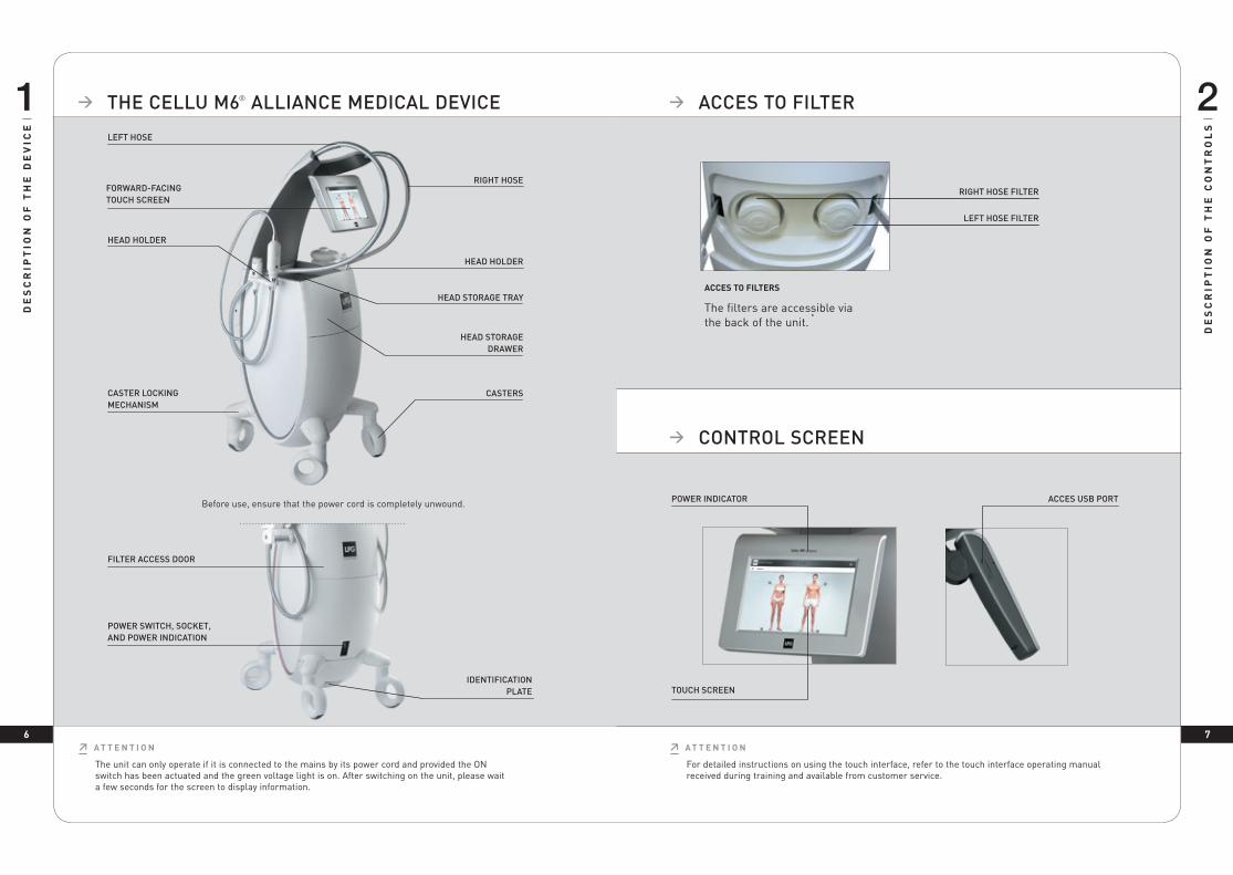
Don’t mobilize the motorized flap manually.
≥ A T T E N T I O N
THE ALLIANCE 50 HEAD 1. Remove the sealing flaps (2 up flaps and 1 down flap) as showed in the pictures below
(fig 1 to 4).
2. Thoroughly rub for at least one minute with the wipes as describe here below.: a) Flaps and their housing (fig 5 to 7). b) The casing on both sides of the rollers (turn the head over, rotate the rollers
manually to clean the entire surface) (fig. 8) c) The motorized flap (Don’t mobilize the motorized flap) (fig 9 & 10). d) Le sabot
3. Reattach the sealing flaps
4. Maintain the storage drawer using LPG wipes, then place the head in it.
THE TR30 HEAD 1. Remove the sealing flaps as showed in the pictures below (fig 1).
2. Thoroughly rub for at least one minute with the wipes as describe here below: a) The flaps and their housing (fig 2 & 3). b) The casing on both sides of the rollers (turn the head over, rotate the rollers
manually to clean the entire surface) (fig. 4) c) Le sabot
3. Reattach the sealing flaps
4. Maintain the storage drawer using LPG wipes, then place the head in it.
TR
EA
TM
EN
T H
EA
DS
TR
EA
TM
EN
T H
EA
DS
Fig 1 Fig 2 Fig 3 Fig 4
Fig 5 Fig 6
Fig 7
Fig 8
Fig 9 Fig 10
Fig 1
Fig 2
Fig 3 Fig 4
3 73 6
77
TR
EA
TM
EN
T H
EA
DS
TR
EA
TM
EN
T H
EA
DS
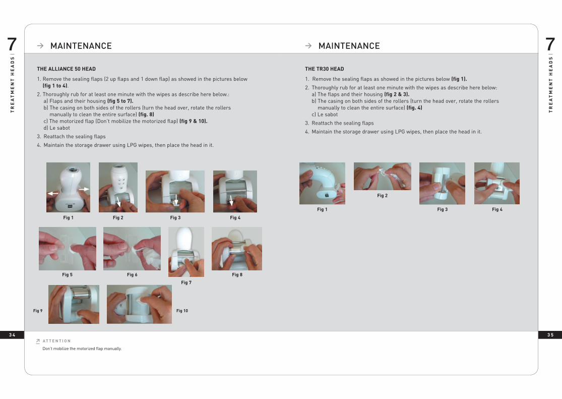
FIG. 3
FIG. 1
FIG. 2
1. Disconnect the micro-heads or micro-nozzles from the adapter.
2. For the micro-heads, use the dedicated tool provided (fig 1 & 2).
3. Thoroughly rub for at least 1 minute the rollers, seal, treatment chamber, microheads disassembly tool, and micro-nozzles with LPG wipes soaked in a bactericide and fungicide solution (fig. 3).
4. Refit the rollers and check they spin freely.
5. To maintain the micro-heads use cotton soaked with the same solution.
6. Maintain the storage drawer using LPG wipes, then place the heads in it.
MICRO-HEADS AND MICRO-NOZZLES
> MAINTENANCE > MAINTENANCE
DESINFECTING THE MICRO-HEADS AND MICRO-NOZZLES The motorized treatment heads (Alliance 80, Alliance 50 and TR30) need to be used with an Endermowear suit. Non-motorized treatment heads (micro-nozzles, and micro-heads) can be used directly on the skin in specific cases.
In these cases, the heads need to be disinfected after each use:
1. Use the maintenance procedure described above.2. Soak the rollers, micro-heads, disassembly tool, and micro-nozzles in a disinfectant for
12 minutes at 20° C, as recommend on the disinfectant packaging.3. Carefully rinse the flap and the treatment chamber with sterile or drinking water for at
least 1 minute using a large volume of water (approximately 8 liters). Repeat twice for a total of 3 rinses.
4. Dry the parts.5. Pre-clean the storage drawer using LPG wipes, then place the head in it.
Use a disinfectant whose active ingredient is ortho-phthalaldehyde (OPA). Before using the disinfectant, read and follow the recommendations, contraindications, and warnings associated with this product. Refer to the instructions for using this solution. All the procedures described in this section must be carried out with the machine turned off and the power cord unplugged. - Do not use corrosive products such as acetone, trichloroethylene, or rubbing alcohol, nor abrasive sponges.
≥ A T T E N T I O N

3 93 8 3 9
87 > MAINTENANCE
> ENDERMOWEARTM
LPG EndermowearTM is available in several sizes for men and women and has been specially designed for body treatments. It is intended for personal use, guarantees hygiene, and its opaque areas cover the patient’s intimate parts during the treatment. EndermowearTM’s unique material guarantees excellent adhesion to the skin which facilitates movement of the treatment head.
The products are delivered in a bag that the customer can personalize by putting their name on the label. It becomes the customer’s property and can be used for several sessions. For esthetic reasons and hygiene, it should be washed after each use. Please refer to the washing instructions indicated on the bag label.
TR
EA
TM
EN
T H
EA
DS
EN
DE
RM
OW
EA
RTM
ERGOLIFT HEAD AND ERGOLIFT CHAMBERS
FIG. 3
FIG. 1 REMOVAL TOOLS
FIG. 2 ROTATION 90°
ROTATION 90° FIG. 4
DESINFECTING OF ERGOLIFT CHAMBERS
The use of aggressive products, such as acetone, trichloroethylene, or alcohol at 90°, and abrasive sponges, ultrasound or UV lamps is strictly prohibited. All cleaned and/or disinfected heads should be placed in the storage drawer to avoid any confusion. Use a disinfectant whose active ingredient is ortho-phthalaldehyde (OPA). Before using the disinfectant, read and follow the recommendations, contraindications, and warnings associated with this product. Refer to the instructions for using this solution. All the procedures described in this section must be carried out with the machine turned off and the power cord unplugged.
≥ A T T E N T I O N
For reasons of hygiene, the maintenance of the treatment heads should be performed after each use, using antiseptic wipes impregnated with a bactericidal and fungicidal solution. Special attention must be given to the rub of the parts that are in contact with the patient.
1. Disconnect the chamber from the Ergolift treatment head. (fig. 1) 2. Remove the flap thanks to the dedicated tool. (fig. 2)3. Thoroughly rub the Ergolift chamber, the flap and the tool for at least one minute with the wipes as describe here below. (fig. 3)4. Put the flap back in the Ergolift chamber by following the same steps in the reverse order (fig. 4)
The Ergolift head is in direct contact with patient’s skin. Under certain specific applications, it needs to be disinfected after each use:
1. Follow the maintenance procedure described above.
2. Soak the flap and Ergolift chamber in an OPA disinfectant for 12 minutes at 20° C, as recommended on the disinfectant packaging.
3. Carefully rinse the flap and the Ergolift chamber with sterile or drinking water for at least 1 minute using a large volume of water (approximately 8 liters). Repeat twice for a total of 3 rinses.
4. Dry the Ergolift chamber and flap.
5. Clean the storage drawer with antiseptic wipes, then place the Ergolift chamber and flap in it.
> MAINTENANCE

4 0 4 1
GE
NE
RA
L W
AR
RA
NT
Y C
ON
DIT
ION
S
9
GE
NE
RA
L W
AR
RA
NT
Y C
ON
DIT
ION
S
9 > GENERAL WARRANTY CONDITIONS > GENERAL WARRANTY CONDITIONS
You have recently acquired an appliance distributed by LPG Systems or an LPG Systems approved distributor. It is the purchaser/user’s responsibility to find out from the local authorities the conditions and professional qualifications required before using the appliance.
The purchase of this equipment implies the legal acceptance by the purchaser/ professional user of these general warranty conditions. If the appliance was sold to you by an approved LPG Systems distributor, the purchaser/user should refer to the supplier’s warranty conditions. These may in no way increase the undertakings made by LPG in these present warranty conditions. The warranty can only be implemented and is only valid if the warranty slip has been duly filled out and returned to LPG Systems within two weeks of delivery, irrespective of the country. Warranty slips that are only partially completed will be rejected. The appliance is guaranteed against manufacturing flaws and defects in the raw materials.
The warranty extends for the shorter of the following two periods: one (1) year OR two thousand (2000) hours of use from the invoice date. During this period, LPG Systems undertakes to exchange or repair free of charge, as quickly as possible, any part that LPG Systems acknowledges as defective,
however LPG Systems does not undertake to replace the entire appliance.
Traveling and living expenses for our technicians and transportation costs of the appliance or parts to and from the aftersales service workshop are not covered by this warranty. Replacements and repairs performed within this warranty, with or without immobilization of the equipment, shall not have the effect of extending the warranty period.
Replaced parts become the property of LPG Systems or the approved distributor. No compensation shall be paid for loss of use. Subject to other conditions hereafter, warranty shall apply if the purchaser/professional user has allowed LPG to proceed to necessary repair works.
Warranty exclusion:
• Damage occurring during transportation. Transportation of this equipment and/or spare parts is at the recipient’s own risk. Before taking delivery, it is the recipient’s responsibility to verify the state of the goods and to make a claim against the transport company in the manner usual in the delivery country.
• Non-observance of the installation and operating instructions, failure to carry out maintenance and/or negligence in maintaining the appliance and/or its filter cartridges, connection to a faulty electricity supply or a non-earthed electricity supply or a power supply whose voltage is different to the one indicated on the appliance.
• If an appliance is sold before the end of the warranty period, the warranty is transferred to the purchaser for the remaining warranty period, on the condition that: I The original invoice is provided. II That the initial vendor is informed of the
sale.• Modification, mounting of accessories or
dismantling of the equipment.
• Any operation and/or intervention not specified in the LPG Systems Operating Instructions and performed on the equipment by the purchaser/user and/or any party not approved by LPG Systems.
• Use of consumables, spare parts, inappropriate components or parts not supplied by LPG Systems.
• Blockage of the appliance through aspiration of a foreign body.
• Normal wear and tear of any of the equipment’s parts resulting from normal usage.
• Damages or default resulting of accidental events (falls, impacts...) Damages or default resulting of natural disasters (lightening, water damages...) Fire, negligence or abuses.

4 2 4 3
GE
NE
RA
L W
AR
RA
NT
Y C
ON
DIT
ION
S
9
GE
NE
RA
L W
AR
RA
NT
Y C
ON
DIT
ION
S
9 > GENERAL WARRANTY CONDITIONS > WARRANTY ACTIVATION
> OR FILL IN THE FORM AND RETURN TO LPG SYSTEMS
The warranty is limited to the replacement of the components of the device which comply with conditions described above. Under no circumstances shall LPG be liable for any loss or damage as a result or in connection with the device and/or its use, including any financial loss, loss of margin, loss of use, etc. This clause shall apply under any and all legal basis.Whenever the above restriction may not be applicable or enforceable, LPG liability shall be limited to the price for the device and/or the service.
You can activate your warranty online by connecting to our warranty webpage:
http://warranty.lpgsystems.com
≥ A T T E N T I O N
The personal data collected in this form are sent to LPG Systems, which is responsible for processing it in order to manage customers relations, including after-sales service and warranties. Information with an asterisk must be provided in order for this form to be processed. According to modified French law 78-17 from January 6, 1978 relating to computers, digital files, and freedoms, also known as the “Informatique et Libertés” law, you have a right of access, rectify, and remove personal data about you by contacting LPG Systems in writing at the following address: LPG SYSTEMS – 30, rue Dr Abel – Technoparc de la Plaine – 26000 VALENCE (FRANCE).
Name*: . . . . . . . . . . . . . . . . . . . . . . . . . . . . . . . . . . . . . . . . . . . . . . . . . . . . . . . . . . . . . . . . . . . . . . . .
Address*: . . . . . . . . . . . . . . . . . . . . . . . . . . . . . . . . . . . . . . . . . . . . . . . . . . . . . . . . . . . . . . . . . . . . . .
Country*: . . . . . . . . . . . . . . . . . . . . . . . . . . . . . . . . . . . . . . . . . . . . . . . . . . . . . . . . . . . . . . . . . . . . . .
Tel*: . . . . . . . . . . . . . . . . . . . . . . . . . . . . . . . . . . . . . . . . . . . . . . . . . . . . . . . . . . . . . . . . . . . . . . . . . . .
Email: . . . . . . . . . . . . . . . . . . . . . . . . . . . . . . . . . . . . . . . . . . . . . . . . . . . . . . . . . . . . . . . . . . . . . . . . .
Type of business: . . . . . . . . . . . . . . . . . . . . . . . . . . . . . . . . . . . . . . . . . . . . . . . . . . . . . . . . . . . . . . . .
Profession: . . . . . . . . . . . . . . . . . . . . . . . . . . . . . . . . . . . . . . . . . . . . . . . . . . . . . . . . . . . . . . . . . . . . .
Type of unit: CELLU M6® ALLIANCE MEDICAL
Serial number*: . . . . . . . . . . . . . . . . . . . . . . . . . . . . . . . . . . . . . . . . . . . . . . . . . . . . . . . . . . . . . . . . .
Date: . . . . . . . . . . . . . . . . . . . . . . . . . . . . . . . . . . . . . . . . . . . . . . . . . . . . . . . . . . . . . . . . . . . . . . . . . .
To validate the warranty, detach this slip and return to the address below within 15 days following use of the unit:
LPG SYSTEMS® SA – Technoparc de la plaine-30, rue du docteur Abel – CS 90035 – 26902 VALENCE Cedex 9 – France

4 54 4
EL
EC
TR
OM
AG
NE
TIC
CO
MP
AT
IBIL
ITY
10
EL
EC
TR
OM
AG
NE
TIC
CO
MP
AT
IBIL
ITY
10 > APPENDIX: ELECTROMAGNETIC COMPATIBILITY > APPENDIX: ELECTROMAGNETIC COMPATIBILITY
TABLE 1: DIRECTIVES AND MANUFACTURER DECLARATION – ELECTROMAGNETIC EMISSIONS
CELLU M6® ALLIANCE is intended for use in the electromagnetic environment specified below. The CELLU M6® ALLIANCE customer or patient should ensure that it is used in such an environment.
Emissions test Conformity Electromagnetic Environment - Directives
RF emissions CISPR 11 Group 1 CELLU M6® ALLIANCE uses RF energy only for its internal functions. Therefore, its RF emissions are very low and unlikely to cause interference in nearby electronic devices.
RF emissions CISPR 11 Class B CELLU M6® ALLIANCE may be used in all establishments, including domestic sites and sites that are directly connected to the low voltage public power grid, which supplies domestic buildings.
Harmonic emissions IEC 61000-3-2 Class A
Voltage fluctuations and flicker IEC 61000-3-3 Conforms
TABLE 2: DIRECTIVES AND MANUFACTURER DECLARATION – ELECTROMAGNETIC IMMUNITY – EMISSIONS TESTS
CELLU M6® ALLIANCE is intended for use in the electromagnetic environment specified below. The CELLU M6® ALLIANCE customer or patient should ensure that it is used in such an environment.
Emissions test Conformity Conformity Electromagnetic Environment - Directives
Electrostatic discharge (ESD)IEC 61000-4-2
± 6 kV on contact± 8 kV in the air
± 6 kV on contact± 8 kV in the air
Flooring should be made of wood, concrete, or ceramic tile.If the floor is covered with synthetic material, relative humidity should be at least 30%.
Fast transient/burst IEC 61000-4-4
± 2 kV for electrical power lines± 1 kV for input/output lines
± 2 kV for electrical power lines± 1 kV for input/output lines
The quality of the electrical power network should be equivalent to that of a typical commercial or hospital environment.
Surge IEC 61000-4-5
± 1 kV between phases± 2 kV between phase and earth
± 1 kV between phases± 2 kV between phase and earth
The quality of the electrical power network should be equivalent to that of a typical commercial or hospital environment.
Voltage dips, short interruptions, and voltage variationsIEC 61000-4-11
<5% UT(>95% voltage dip)during 0.5 cycle40% UT(60% UT voltage dip)during 5 cycles70% UT(30 % UT voltage dip)during 25 cycles<5% UT(>95% voltage dip)during 5s
<5% UT(>95% voltage dip)during 0.5 cycle40 % UT(60% UT voltage dip)during 5 cycles70% UT(30 % UT voltage dip)during 25 cycles<5% UT(>95% voltage dip)during 5s
The quality of the electrical power network should be equivalent to that of a typical commercial or hospital environment. If the CELLU M6® ALLIANCE patient requires operation to continue during power outages, the CELLU M6® ALLIANCE should be powered through an uninterruptible power supply or a battery.
Power frequency magnetic fieldIEC 61000-4-8
3 A/m 3 A/m Power frequency magnetic fields should have levels that are characteristic of a typical hospital or commercial environment.
NOTE: UT is the AC voltage prior to the application of the test level.
TABLE 3: DIRECTIVES AND MANUFACTURER DECLARATION – ELECTROMAGNETIC IMMUNITY – IMMUNITY TESTS
CELLU M6® ALLIANCE is intended for use in the electromagnetic environment specified below. The CELLU M6® ALLIANCE customer or patient should ensure that it is used in such an environment.
Immunity Test
Test level according to IEC 60601
Conformity level
Electromagnetic environment - directives
Conducted RF disturbances IEC 61000-4-6
3 Veff150 kHz to 80 MHz
3V Portable and mobile RF communications devices should not be used closer to any part of the CELLU M6® ALLIANCE, including its cables, than the recommended separation distance, calculated from the applicable equation on transmitter frequency.Recommended separation distance:d = 1,16√Pd = 1,6√P 80 MHz à 800MHzd = 2,33√P de 800 MHz à 2,5 GHzwhere P is the transmitter’s maximum power output in watts (W), according to the transmitter’s manufacturer, and d is the recommended separation distance in meters (m). The field strength for fixed RF transmitters, as determined by an electromagnetic survey at site a, should be less than the conformity level for each range of frequencies b. Interference may be produced near the device marked with the following symbol:
Perturbations RF rayonnéesCEI 61000-4-3
3 V/mDe 80 MHz to 2,5 GHz
3 V/m
NOTE 1: At 80 MHz and 800 MHz, the highest frequency range applies. NOTE 2: These directives may not apply in all situations. Electromagnetic propagation is affected by absorption and by reflections of structures, objects, and people.
a The field strength of fixed transmitters, such as radio/telephone (cellular/wireless) base stations and land mobile radios, amateur radios, AM and FM radio broadcasting, and TV broadcasting cannot be theoretically predicted with accuracy. To measure the electromagnetic environment due to fixed RF transmitters, consider performing an electromagnetic survey of the site. If the field strength, measured where the CELLU M6® ALLIANCE is used, exceeds the applicable RF conformity level above, watch the CELLU M6® ALLIANCE to ensure that it is operating as normal. If there is any abnormal performance, additional measures may be necessary, such as reorienting or repositioning the CELLU M6® ALLIANCE.
b For the frequency range of 150 kHz to 80 MHz, field strength should be less than 3 V/m.
TABLE 4: RECOMMENDED SEPARATION DISTANCES BETWEEN PORTABLE AND MOBILE RF COMMUNICATION DEVICES AND CELLU M6 ALLIANCE
CELLU M6® ALLIANCE is intended for use in an electromagnetic environment in which radiated RF disturbances are controlled. The CELLU M6® ALLIANCE patient or customer can prevent electromagnetic interference by maintaining a minimal distance between the portable or mobile RF communications device (transmitter) and the CELLU M6® ALLIANCE, as recommended below, based on the maximum transmission power of the communication device.
Maximum rated output of the
transmitter W
Separation distance according to the transmitter frequency m
150KKz à 80Mhz d=1,2√P
80Mhz à 800Mhz d=1,2√P
800Mhz à 2,5 Ghz d = 2,3√P
0,01 0,12 0,12 0,23
0,1 0,38 0,38 0,73
1 1,2 1,2 2,3
10 3,8 3,8 7,3
100 12 12 23
For transmitters whose maximum rated output is not shown above, the recommended separation distance d in meters (m) can be estimated using the applicable equation for the transmitter frequency, where P is the transmitter’s maximum output in watts (W), according to its manufacturer. NOTE 1: At 80 MHz and 800 MHz, the separation distance for the highest frequency range applies. NOTE 2: These directives may not apply in all situations. Electromagnetic propagation is affected by absorption and by reflections of structures, objects, and people.
1571
- E
d 02
/18
- G
B -
© L
PG
Sys
tem
s 20
18 -
LP
G S
yste
ms
SA
au
capi
tal d
e 2
124
950
euro
s -
Sire
n R
CS
335
.183
.836
Rom
ans
- A
ny re
prod
uctio
n –
even
in p
art –
is s
tric
tly p
rohi
bite
d. N
on-b
indi
ng p
hoto
s.
HEADQUARTERS : LPG SYSTEMSTECHNOPARC DE LA PLAINE
30, RUE DU DR. ABEL - CS 9003526902 VALENCE CEDEX 09 - FRANCE
TEL.: +33 (0)4 75 78 69 00 - FAX: +33 (0)4 75 42 80 85
INTERNATIONAL/MARKETING2753, ROUTE DES DOLINES - BP 243
06905 SOPHIA-ANTIPOLIS CEDEX - FRANCETEL.: +33 (0)4 92 38 39 00 - FAX: +33 (0)4 92 96 09 65