Cell Libraries and Design Hierarchy Libraries and... · primitive library cells added as to higher...
14
Cell Libraries and Design Hierarchy Instructor S. Demlow ECE 410 February 1, 2012
Transcript of Cell Libraries and Design Hierarchy Libraries and... · primitive library cells added as to higher...
Cell Libraries and Design Hierarchy
Instructor S. Demlow ECE 410 February 1, 2012
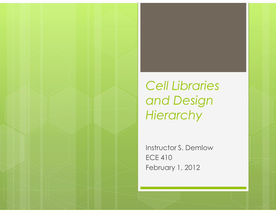
Stick Diagrams Simplified NAND Layout
Metal supply rails blue
n and p Active green
Poly gates red
Metal connections supply, outputs
Contacts black X
N-Well (optional) dashed rectangle
VDD
ground
a
out
b X X X
X X
Simplified NOR Layout
VDD
ground
a
out
b X
X
X
X X
Overview We previously covered layouts of basic
logic functions like NAND and NOR We’ve extended our discussion to the
physical layouts of complex logic gates How can we use these kinds of designs to
implement more complex functions?
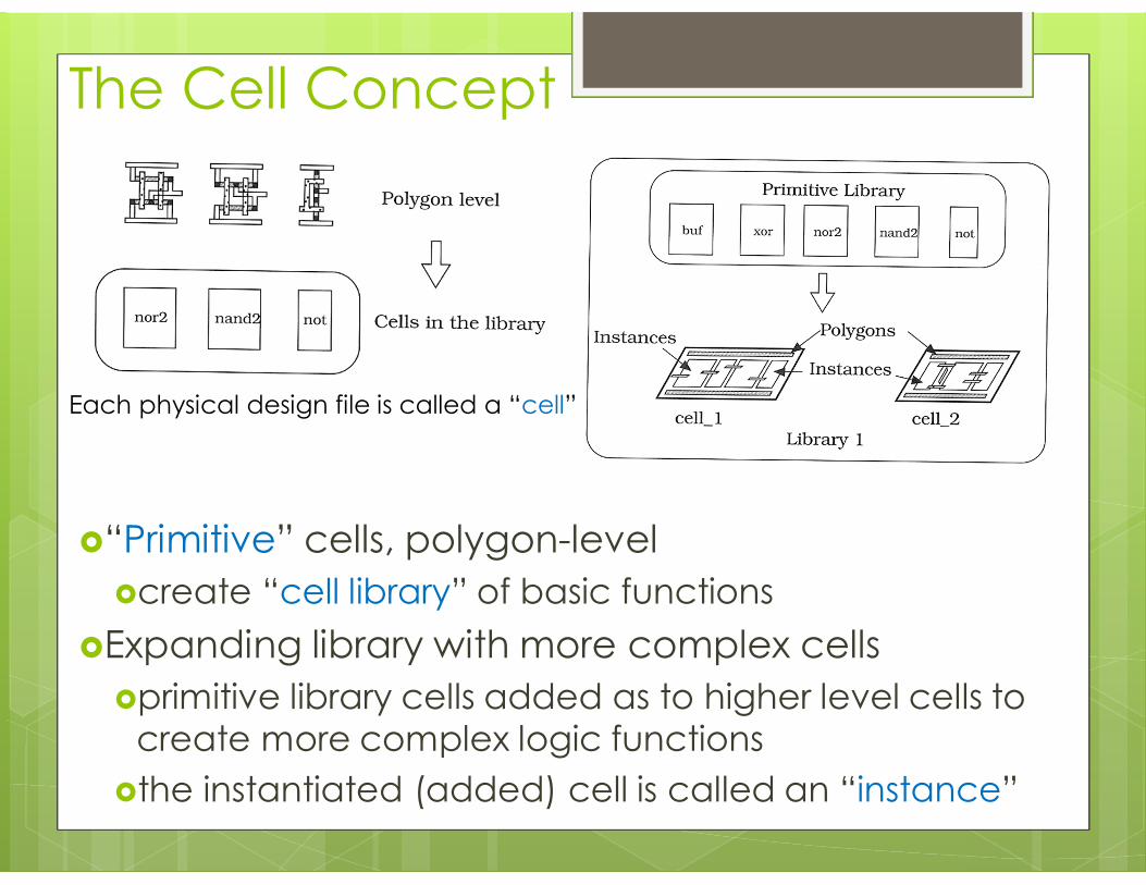
The Cell Concept
“Primitive” cells, polygon-level create “cell library” of basic functions
Expanding library with more complex cells primitive library cells added as to higher level cells to
create more complex logic functions the instantiated (added) cell is called an “instance”
Each physical design file is called a “cell”
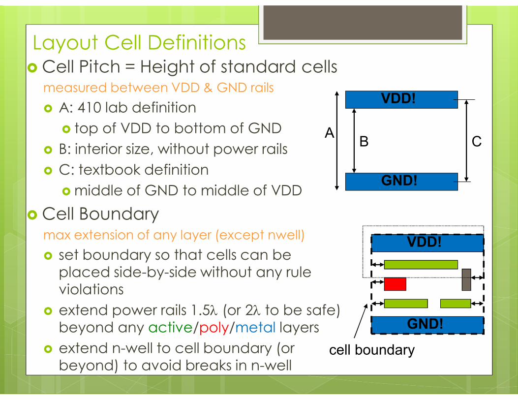
Layout Cell Definitions Cell Pitch = Height of standard cells
measured between VDD & GND rails A: 410 lab definition
top of VDD to bottom of GND B: interior size, without power rails C: textbook definition
middle of GND to middle of VDD Cell Boundary
max extension of any layer (except nwell) set boundary so that cells can be
placed side-by-side without any rule violations
extend power rails 1.5l (or 2l to be safe) beyond any active/poly/metal layers
extend n-well to cell boundary (or beyond) to avoid breaks in n-well
VDD!
GND!
A B C
VDD!
GND!
cell boundary
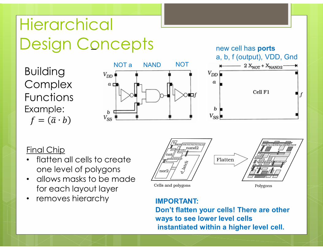
Hierarchical Design Concepts
NOT a NAND NOT
new cell has ports a, b, f (output), VDD, Gnd
IMPORTANT: Don’t flatten your cells! There are other ways to see lower level cells instantiated within a higher level cell.
Building Complex Functions Example: 푓 = 푎 ∙ 푏
Final Chip • flatten all cells to create
one level of polygons • allows masks to be made
for each layout layer • removes hierarchy
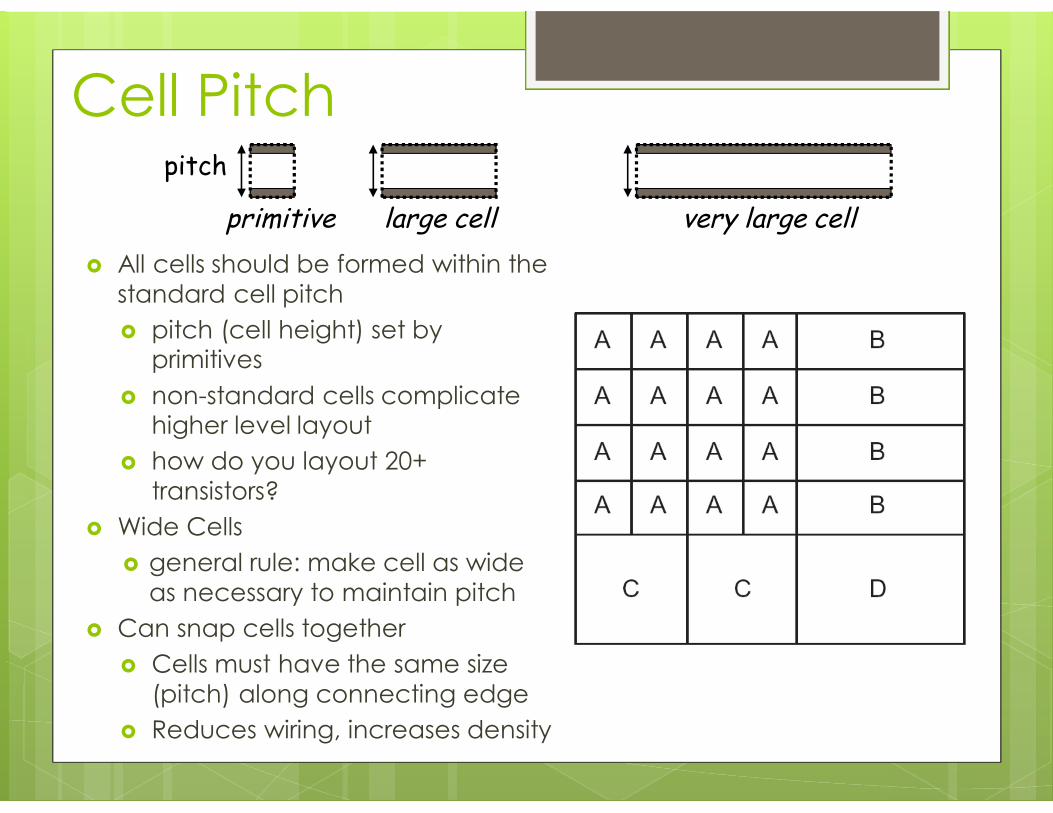
Cell Pitch
All cells should be formed within the standard cell pitch pitch (cell height) set by
primitives non-standard cells complicate
higher level layout how do you layout 20+
transistors? Wide Cells
general rule: make cell as wide as necessary to maintain pitch
Can snap cells together Cells must have the same size
(pitch) along connecting edge Reduces wiring, increases density
primitive
pitch
large cell very large cell

Application of pitch matched cells: Microprocessor datapath bitslices
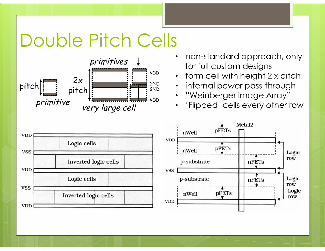
Double Pitch Cells
primitive
pitch
very large cell
primitives
2x pitch
VDD GND GND VDD
• non-standard approach, only for full custom designs
• form cell with height 2 x pitch • internal power pass-through • “Weinberger Image Array” • ‘Flipped’ cells every other row

Pitch selection tradeoffs
Horizontal Tx (W runs vertically) can increase tx W with
fixed pitch
cells short & wide Vertical Tx
(W runs horizontally) pitch sets max tx W cells taller & narrow Often best packing
density – 2 active region design methodology
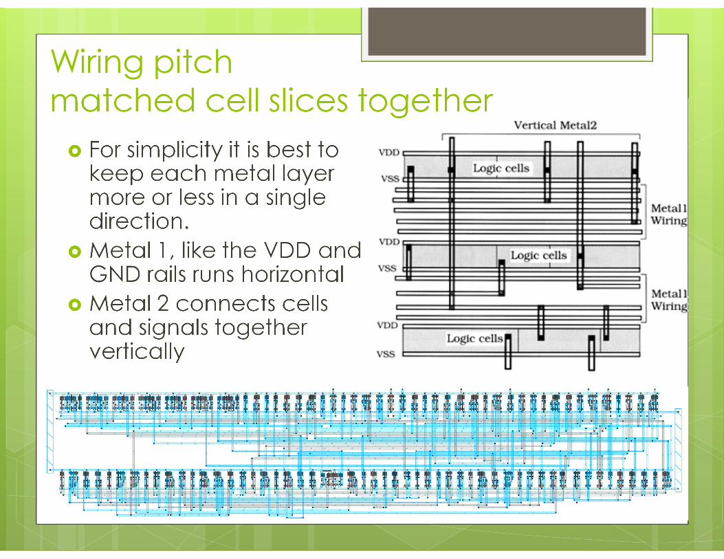
Wiring pitch matched cell slices together For simplicity it is best to
keep each metal layer more or less in a single direction.
Metal 1, like the VDD and GND rails runs horizontal
Metal 2 connects cells and signals together vertically

NAND/NOR Layout Alternatives vertical transistors
for smaller pitch (height) and wider cell
large horizontal transistors for larger pitch
(height) and narrower cell
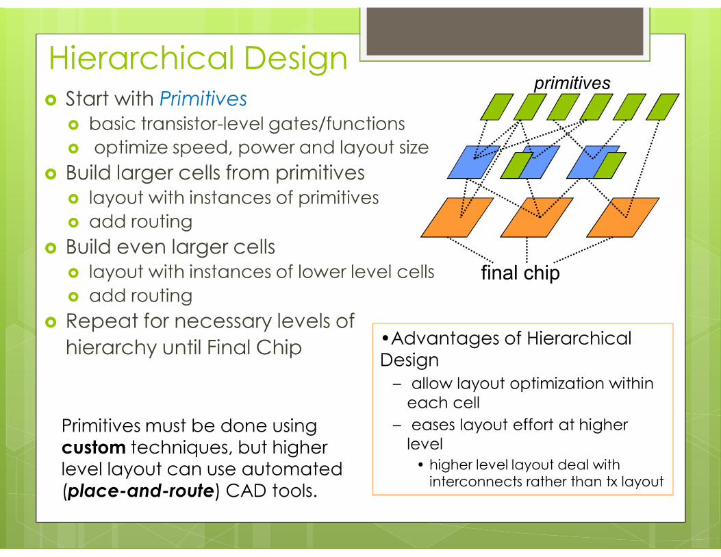
Hierarchical Design Start with Primitives
basic transistor-level gates/functions optimize speed, power and layout size
Build larger cells from primitives layout with instances of primitives add routing
Build even larger cells layout with instances of lower level cells add routing
Repeat for necessary levels of hierarchy until Final Chip
final chip
primitives
Primitives must be done using custom techniques, but higher level layout can use automated (place-and-route) CAD tools.
•Advantages of Hierarchical Design
– allow layout optimization within each cell
– eases layout effort at higher level
• higher level layout deal with interconnects rather than tx layout
Overview We’ve learned about pitch matching, cells,
libraries, and hierarchical design We discussed the tradeoffs between
vertical and horizontal transistors, and the factors to consider when selecting cell pitch
We saw the advantages of hierarchical design and pitch matched cells, including automation and simplification of design