CEILING WALL SYSTEMS - Armstrong
24
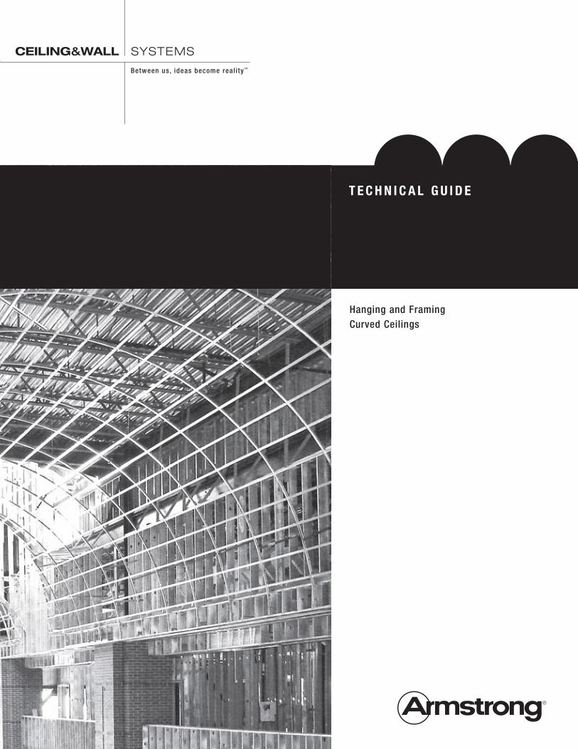
DRYWALL Grid Systems Hanging and Framing Curved Ceilings TECHNICAL GUIDE CEILING&WALL SYSTEMS Between us, ideas become reality ™
Transcript of CEILING WALL SYSTEMS - Armstrong
DrywallGrid Systems
Hanging and FramingCurved Ceilings
T e c h n i c a l G u i D e
CEILING&WALL SYSTEMS
Between us, ideas become real i ty ™
co
nte
nts
Drywall Grid Systems
Table of Contents
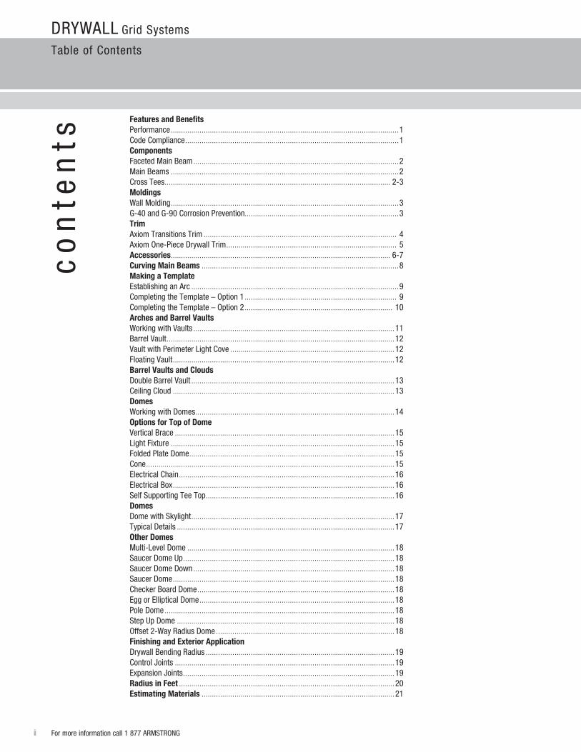
Features and BenefitsPerformance ...............................................................................................................1Code Compliance ........................................................................................................1componentsFaceted Main Beam ....................................................................................................2Main Beams ...............................................................................................................2Cross Tees .............................................................................................................. 2-3Moldingswall Molding ...............................................................................................................3G-40 and G-90 Corrosion Prevention...........................................................................3Trimaxiom Transitions Trim .............................................................................................. 4axiom One-Piece Drywall Trim ................................................................................... 5accessories ........................................................................................................... 6-7curving Main Beams ................................................................................................8Making a Template Establishing an arc .....................................................................................................9 Completing the Template – Option 1 .......................................................................... 9Completing the Template – Option 2 ........................................................................ 10arches and Barrel Vaultsworking with Vaults ..................................................................................................11Barrel Vault ...............................................................................................................12Vault with Perimeter light Cove ................................................................................12Floating Vault ............................................................................................................12Barrel Vaults and cloudsDouble Barrel Vault ...................................................................................................13Ceiling Cloud ............................................................................................................13Domesworking with Domes .................................................................................................14Options for Top of DomeVertical Brace ...........................................................................................................15light Fixture .............................................................................................................15Folded Plate Dome ....................................................................................................15Cone .........................................................................................................................15Electrical Chain .........................................................................................................16Electrical Box ............................................................................................................16Self Supporting Tee Top ............................................................................................16DomesDome with Skylight ...................................................................................................17Typical Details ..........................................................................................................17Other DomesMulti-level Dome .....................................................................................................18Saucer Dome Up .......................................................................................................18Saucer Dome Down ..................................................................................................18Saucer Dome ............................................................................................................18Checker Board Dome ................................................................................................18Egg or Elliptical Dome ...............................................................................................18Pole Dome ................................................................................................................18Step Up Dome ..........................................................................................................18Offset 2-way radius Dome .......................................................................................18Finishing and exterior applicationDrywall Bending radius ............................................................................................19Control Joints ...........................................................................................................19Expansion Joints .......................................................................................................19radius in Feet .........................................................................................................20estimating Materials ..............................................................................................21
ii For more information call 1 877 arMSTrONG
fea
ture
s a
nd
be
ne
fits
Drywall Grid Systems
Features and Benefits
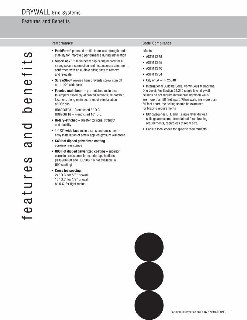
Performance Code Compliance
• PeakForm® patented profile increases strength and stability for improved performance during installation
• Superlock™ 2 main beam clip is engineered for a strong secure connection and fast accurate alignment confirmed with an audible click; easy to remove and relocate
• ScrewStop® reverse hem prevents screw spin off on 1-1/2" wide face
• Faceted main beam – pre-notched main beam to simplify assembly of curved sections; all notched locations along main beam require installation of rC2 clip
HD8906F08 – Prenotched 8" O.C. HD8906F16 – Prenotched 16" O.C.
• rotary-stitched – Greater torsional strength and stability
• 1-1/2" wide face main beams and cross tees – easy installation of screw applied gypsum wallboard
• G40 hot dipped galvanized coating – corrosion resistance
• G90 hot dipped galvanized coating – superior corrosion resistance for exterior applications (HD8906F08 and HD8906F16 not available in G90 coating)
• cross tee spacing: 24" O.C. for 5/8" drywall 16" O.C. for 1/2" drywall 8" O.C. for tight radius
For more information call 1 877 arMSTrONG 1
Meets:
• ASTMC635
• ASTMC645
• ASTMC840
• ASTMC754
• CityofLA–RR25348
• InternationalBuildingCode,ContinuousMembrane, One level. Per Section 25.210 single level drywall ceilings do not require lateral bracing when walls are more than 50 feet apart. when walls are more than 50feetapart,theceilingshouldbeexamined for bracing requirements
• IBCcategoriesD,EandFsinglelayerdrywall ceilings are exempt from lateral force bracing requirements,regardlessofroomsize.
• Consultlocalcodesforspecificrequirements.
Drywall Grid Systems
Components
2 For more information call 1 877 arMSTrONG
co
mp
on
en
ts
1/4"
9/16"
1-11/16"
1-1/2"
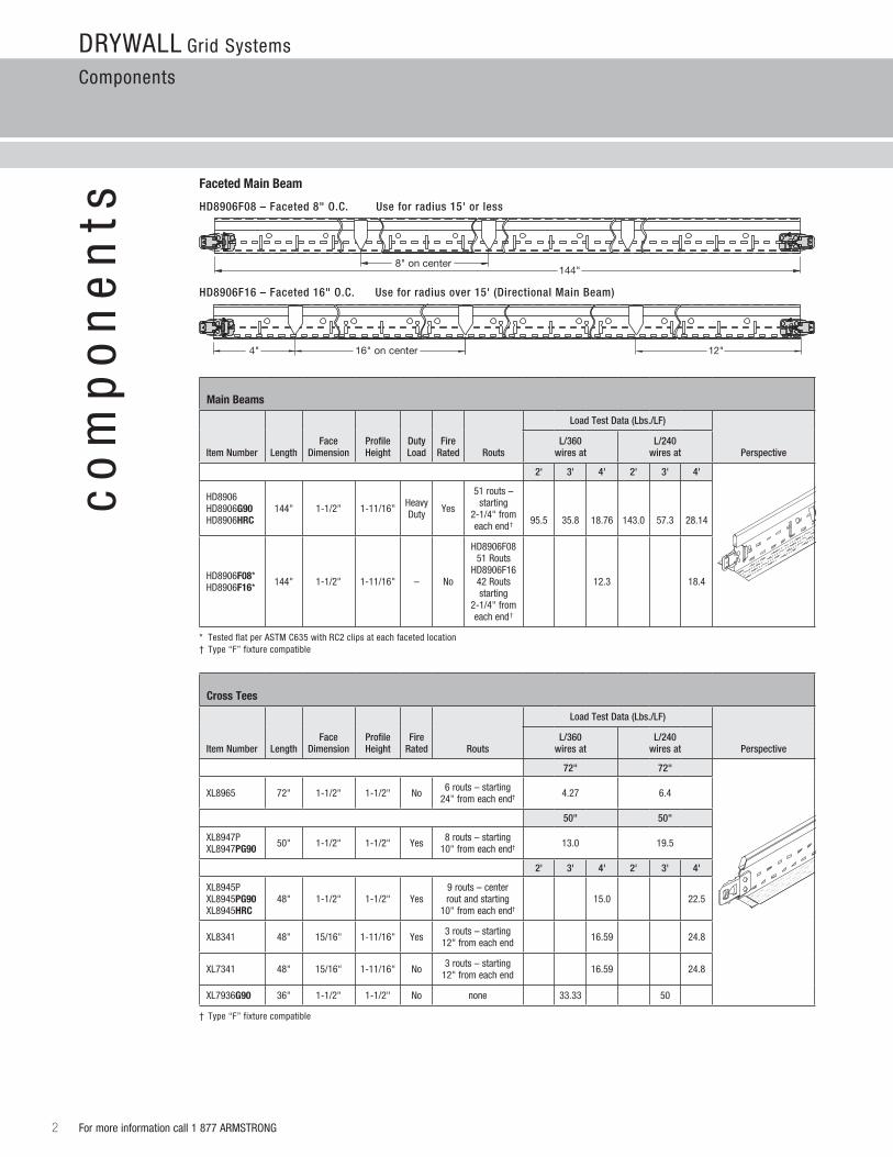
Main Beams
Item Number
LengthFace
DimensionProfileHeight
DutyLoad
FireRated Routs
Load Test Data (Lbs./LF)
PerspectiveL/360
wires atL/240
wires at
2' 3' 4' 2' 3' 4'
HD8906HD8906G90HD8906hrc
144" 1-1/2" 1-11/16" Heavy Duty yes
51 routs – starting
2-1/4" from each end† 95.5 35.8 18.76 143.0 57.3 28.14
HD8906F08*HD8906F16* 144" 1-1/2" 1-11/16" – No
HD8906F08 51 routs
HD8906F16 42 routs starting
2-1/4" from each end†
12.3 18.4
* Tested flat per aSTM C635 with rC2 clips at each faceted location† Type “F” fixture compatible
Faceted Main Beam
1/4"
9/16"
1-11/16"
1-1/2"
cross Tees
Item Number
LengthFace
DimensionProfileHeight
FireRated Routs
Load Test Data (Lbs./LF)
PerspectiveL/360
wires atL/240
wires at
72" 72"
Xl8965 72" 1-1/2" 1-1/2" No 6 routs – starting 24" from each end† 4.27 6.4
50" 50"
Xl8947P Xl8947PG90 50" 1-1/2" 1-1/2" yes 8 routs – starting
10" from each end† 13.0 19.5
2' 3' 4' 2' 3' 4'
Xl8945P Xl8945PG90 Xl8945hrc
48" 1-1/2" 1-1/2" yes9 routs – center rout and starting
10" from each end†15.0 22.5
Xl8341 48" 15/16" 1-11/16" yes 3 routs – starting 12" from each end 16.59 24.8
Xl7341 48" 15/16" 1-11/16" No 3 routs – starting 12" from each end 16.59 24.8
Xl7936G90 36" 1-1/2" 1-1/2" No none 33.33 50
† Type “F” fixture compatible
HD8906F08 – Faceted 8" O.C. Use for radius 15' or less
HD8906F16 – Faceted 16" O.C. Use for radius over 15' (Directional Main Beam)
8" on center 144"
16" on center4" 12"
8" on center 144"
16" on center4" 12"
Drywall Grid Systems
Components and Moldings
3For more information call 1 877 arMSTrONG
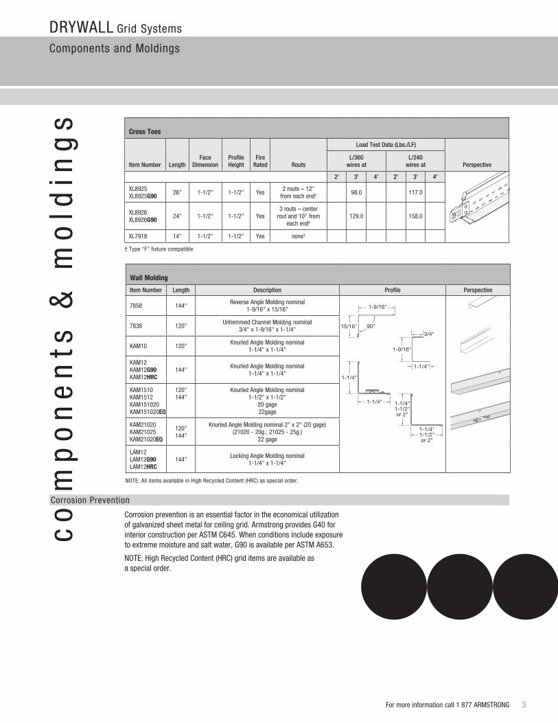
Corrosionpreventionisanessentialfactorintheeconomicalutilizationofgalvanizedsheetmetalforceilinggrid.ArmstrongprovidesG40forinterior construction per aSTM C645. when conditions include exposure toextrememoistureandsaltwater,G90isavailableperASTMA653.
NOTE: High recycled Content (HrC) grid items are available as a special order.
Corrosion Prevention
1/4"
9/16"
1-11/16"
1-1/2"
cross Tees
Item Number
LengthFace
DimensionProfileHeight
FireRated Routs
Load Test Data (Lbs./LF)
PerspectiveL/360
wires atL/240
wires at
2' 3' 4' 2' 3' 4'
Xl8925Xl8925G90 26" 1-1/2" 1-1/2" yes 2 routs – 12"
from each end† 98.0 117.0
Xl8926 Xl8926G90 24" 1-1/2" 1-1/2" yes
3 routs – center rout and 10" from
each end†129.0 158.0
Xl7918 14" 1-1/2" 1-1/2" yes none†
† Type “F” fixture compatible
co
mp
on
en
ts &
mo
ldin
gs
11/2/987858PRO
90°
12/14/98
1/28/99
15/16"
1-9/16"
3/4"
1-9/16"
1-1/4"
1-1/4"
1-1/4"
NOTE: all items available in High recycled Content (HrC) as special order.
1-1/4"1-1/2"or 2"
1-1/4"1-1/2"or 2"
wall Molding
Item Number Length Description Profile Perspective
7858 144"reverse angle Molding nominal
1-9/16" x 15/16"
7838 120"Unhemmed Channel Molding nominal
3/4" x 1-9/16" x 1-1/4"
KaM10 120"Knurled angle Molding nominal
1-1/4" x 1-1/4"
KaM12 KaM12G90 KaM12hrc
144" Knurled angle Molding nominal1-1/4" x 1-1/4"
KaM1510 KaM1512KaM151020 KaM151020eQ
120" 144"
Knurled angle Molding nominal 1-1/2" x 1-1/2"
20 gage 22gage
KaM21020 KaM21025 KaM21020eQ
120" 144"
Knurled angle Molding nominal 2" x 2" (20 gage) (21020 - 20g.; 21025 - 25g.)
22 gage
laM12laM12G90laM12hrc
144" locking angle Molding nominal 1-1/4" x 1-1/4"
tra
ns
itio
ns
tri
mDrywall Grid Systems
axiom Trim
4 For more information call 1 877 arMSTrONG
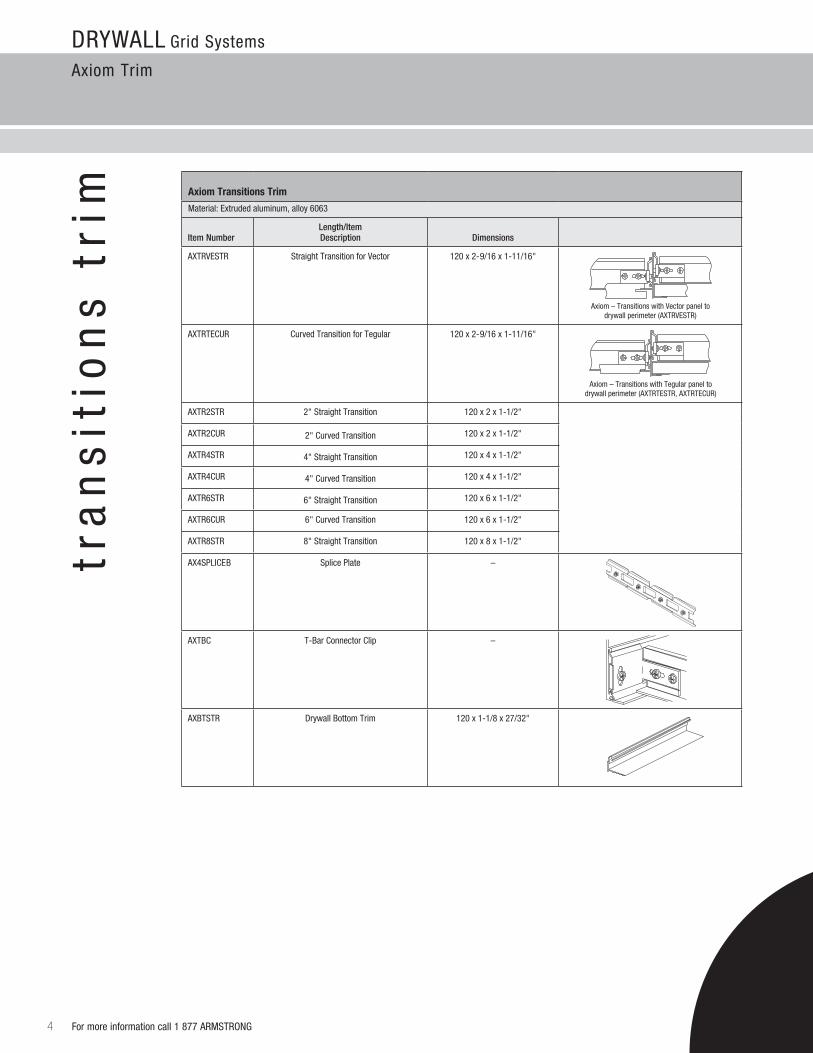
axiom Transitions Trim
Material:Extrudedaluminum,alloy6063
Item NumberLength/Item Description
Dimensions
aXTrVESTr Straight Transition for Vector 120 x 2-9/16 x 1-11/16"
aXTrTECUr Curved Transition for Tegular 120 x 2-9/16 x 1-11/16"
aXTr2STr 2" Straight Transition 120 x 2 x 1-1/2"
aXTr2CUr 2" Curved Transition 120 x 2 x 1-1/2"
aXTr4STr 4" Straight Transition 120 x 4 x 1-1/2"
aXTr4CUr 4" Curved Transition 120 x 4 x 1-1/2"
aXTr6STr 6" Straight Transition 120 x 6 x 1-1/2"
aXTr6CUr 6" Curved Transition 120 x 6 x 1-1/2"
aXTr8STr 8" Straight Transition 120 x 8 x 1-1/2"
AX4SPLICEB Splice Plate –
aXTBC T-Bar Connector Clip –
aXBTSTr Drywall Bottom Trim 120 x 1-1/8 x 27/32"
axiom – Transitions with Vector panel to drywall perimeter (aXTrVESTr)
axiom – Transitions with Tegular panel to drywall perimeter (AXTRTESTR,AXTRTECuR)
AXTBC - TEE-BAR CONNECTIONCLIP
Drywall Grid Systems
axiom Trim
5For more information call 1 877 arMSTrONG
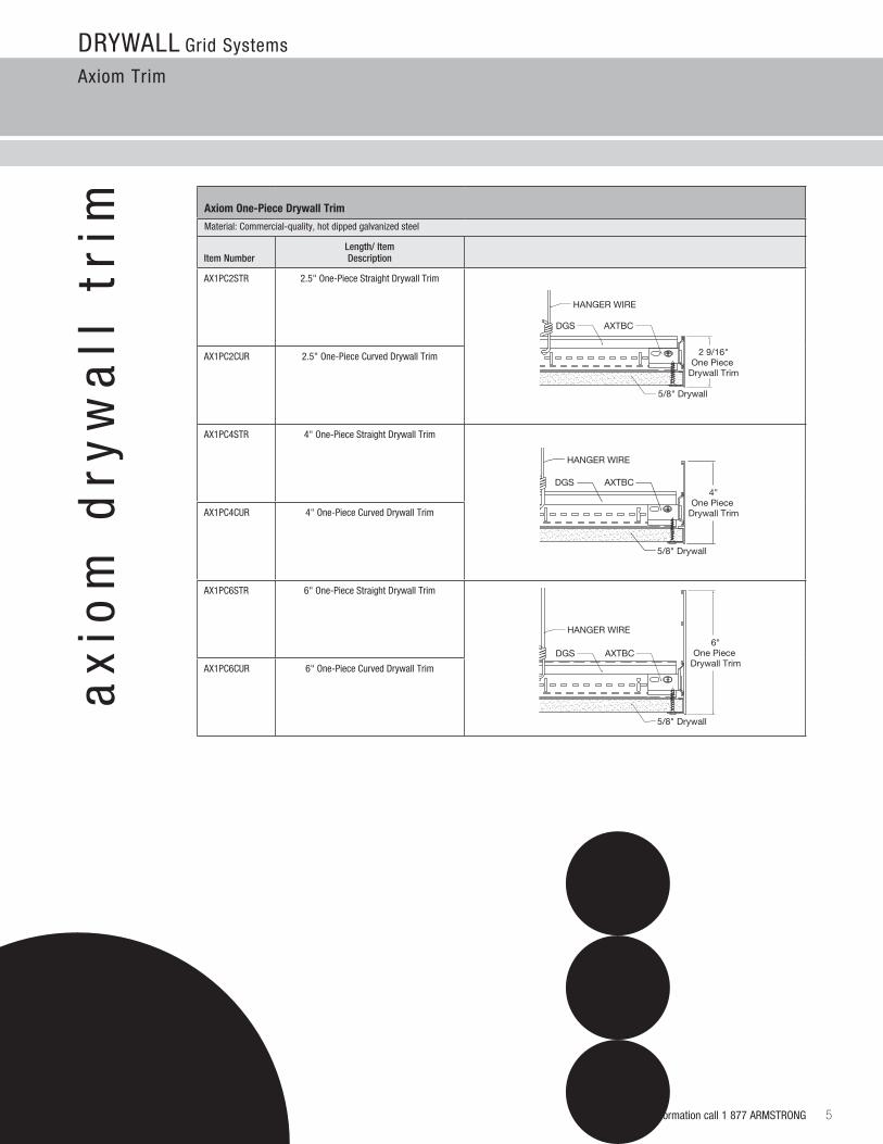
axiom One-Piece Drywall Trim
Material:Commercial-quality,hotdippedgalvanizedsteel
Item NumberLength/ Item Description
aX1PC2STr 2.5" One-Piece Straight Drywall Trim
aX1PC2CUr 2.5" One-Piece Curved Drywall Trim
aX1PC4STr 4" One-Piece Straight Drywall Trim
aX1PC4CUr 4" One-Piece Curved Drywall Trim
aX1PC6STr 6" One-Piece Straight Drywall Trim
aX1PC6CUr 6" One-Piece Curved Drywall Trim
5/8" Drywall
2 9/16"One Piece
Drywall Trim
DGS AXTBC
HANGER WIRE
5/8" Drywall
DGS AXTBC
HANGER WIRE
4"One Piece
Drywall Trim
5/8" Drywall
DGS AXTBC
HANGER WIRE6"
One Piece Drywall Trim
ax
iom
dry
wa
ll t
rim
Drywall Grid Systems
accessories
6 For more information call 1 877 arMSTrONG
ac
ce
ss
ori
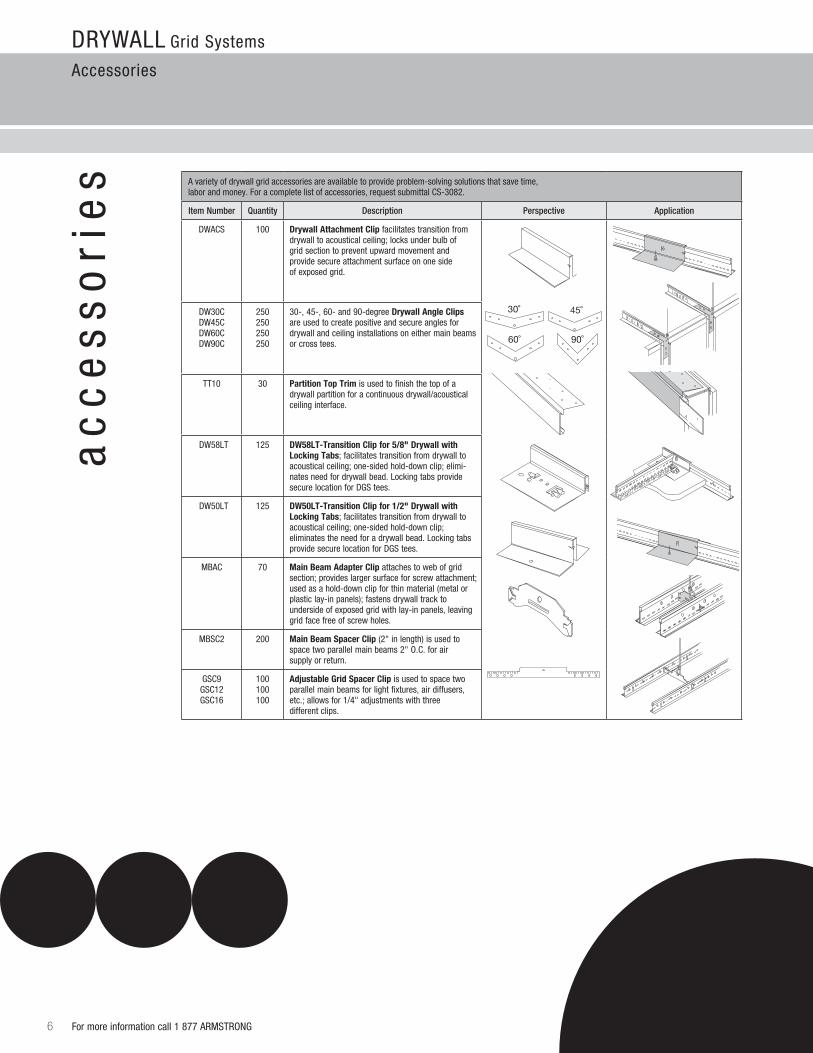
es Avarietyofdrywallgridaccessoriesareavailabletoprovideproblem-solvingsolutionsthatsavetime,
laborandmoney.Foracompletelistofaccessories,requestsubmittalCS-3082.
Item Number Quantity Description Perspective Application
DwaCS 100 Drywall attachment clip facilitates transition from drywall to acoustical ceiling; locks under bulb of grid section to prevent upward movement and provide secure attachment surface on one side of exposed grid.
Dw30CDw45CDw60CDw90C
250250250250
30-,45-,60-and90-degreeDrywall angle clips are used to create positive and secure angles for drywall and ceiling installations on either main beams or cross tees.
TT10 30 Partition Top Trim is used to finish the top of a drywall partition for a continuous drywall/acoustical ceiling interface.
Dw58lT 125 Dw58lT-Transition clip for 5/8" Drywall with locking Tabs; facilitates transition from drywall to acoustical ceiling; one-sided hold-down clip; elimi-nates need for drywall bead. locking tabs provide secure location for DGS tees.
Dw50lT 125 Dw50lT-Transition clip for 1/2" Drywall with locking Tabs; facilitates transition from drywall to acoustical ceiling; one-sided hold-down clip; eliminates the need for a drywall bead. locking tabs provide secure location for DGS tees.
MBaC 70 Main Beam adapter clip attaches to web of grid section; provides larger surface for screw attachment; used as a hold-down clip for thin material (metal or plastic lay-in panels); fastens drywall track to undersideofexposedgridwithlay-inpanels,leavinggrid face free of screw holes.
MBSC2 200 Main Beam Spacer clip (2" in length) is used to space two parallel main beams 2" O.C. for air supply or return.
GSC9 GSC12GSC16
100100 100
adjustable Grid Spacer clip is used to space two parallelmainbeamsforlightfixtures,airdiffusers,etc.; allows for 1/4" adjustments with three different clips.
DWACDWAC
MBACMBAC
30˚ 45˚
60˚ 90˚
For more information call 1 877 arMSTrONG 7
Drywall Grid Systems
accessories
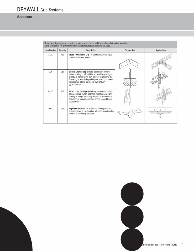
Avarietyofdrywallgridaccessoriesareavailabletoprovideproblem-solvingsolutionsthatsavetime, laborandmoney.Foracompletelistofaccessories,requestsubmittalCS-3082.
Item Number Quantity Description Perspective Application
XTaC 100 cross Tee adapter clip - is used to attach field cut cross tees to main beams
DDC 250 Double Drywall clip to hang suspension system belowexisting1-1/2"gridface,transferringweightdirectly to hanger wire; may be used to preserve the fire rating of an existing ceiling and to support heavy accessories; allows for double layer of 5/8" gypsum board.
DlCC 250 Direct load ceiling clip to hang suspension system belowexisting15/16"gridface,transferringweightdirectly to hanger wire; may be used to preserve the fire rating of an existing ceiling and to support heavy accessories.
DwC 250 Drywall clip allows for a “second” ceiling to be in-stalled below a drywall ceiling; attach through installed drywall to supporting structure.
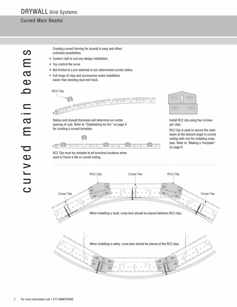
Wheninstallingavault,crossteesshouldbeplacedbetweenRC2clips.
Drywall Grid Systems
Curved Main Beams
8 For more information call 1 877 arMSTrONG
cu
rve
d m
ain
be
am
s Creating curved framing for drywall is easy and offers unlimited possibilities.
• Customradiitosuitanydesigninstallation.
• Youcontrolthecurve.
• Notlimitedtoapre-selectedorpre-determinedcurvedradius.
•Fullrangeofclipsandaccessoriesmakeinstallation easier than bending stud and track.
radius and drywall thickness will determine on-center spacing of cuts. refer to “Establishing an arc” on page 9 for creating a curved template.
rC2 Clip must be installed at all knockout locations when used to frame a flat or curved ceiling.
InstallRC2clipusingfourscrewsper clips.
rC2 Clip is used to secure the main beam at the desired angle in curved ceiling with rout for installing cross tees. refer to “Making a Template” on page 9.
RC2 Clip
RC2 Clip RC2 Clip
Cross Tee Cross Tee
Cross Tee
Wheninstallingavalley,crossteesshouldbeplacedattheRC2clips.
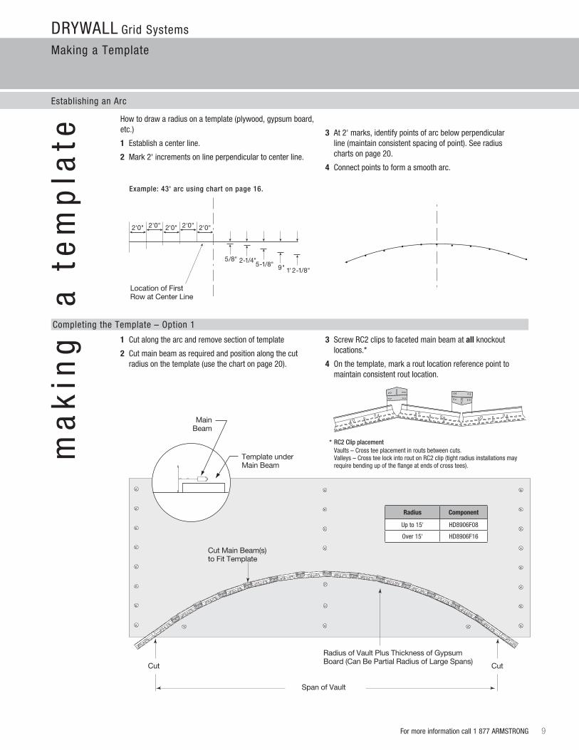
Cut Main Beam(s) to Fit Template
Radius of Vault Plus Thickness of Gypsum Board (Can Be Partial Radius of Large Spans)
CutCut
radius component
Up to 15' HD8906F08
Over 15' HD8906F16
Span of Vault
Main Beam
Template under Main Beam
2'0"2'0"2'0"2'0"2'0"
1' 2-1/8"9"5-1/8"2-1/4"5/8"
Location of First Row at Center Line
Drywall Grid Systems
Making a Template
Establishing an arc
For more information call 1 877 arMSTrONG 9
ma
kin
g
a t
em
pla
te
Completing the Template – Option 1
Howtodrawaradiusonatemplate(plywood,gypsumboard,etc.)
1 Establish a center line.
2 Mark 2' increments on line perpendicular to center line.
3At2'marks,identifypointsofarcbelowperpendicular line (maintain consistent spacing of point). See radius charts on page 20.
4 Connect points to form a smooth arc.
Example: 43' arc using chart on page 16.
1 Cut along the arc and remove section of template
2 Cut main beam as required and position along the cut radius on the template (use the chart on page 20).
3 Screw rC2 clips to faceted main beam at all knockout locations.*
4 Onthetemplate,markaroutlocationreferencepointto maintain consistent rout location.
* RC2 Clip placement Vaults – Cross tee placement in routs between cuts. Valleys – Cross tee lock into rout on rC2 clip (tight radius installations may require bending up of the flange at ends of cross tees).
2'0"2'0"2'0"2'0"2'0"
1' 2-1/8"9"5-1/8"2-1/4"5/8"
Drywall Grid Systems
Making a Template
10 For more information call 1 877 arMSTrONG
Completing the Template – Option 2
ma
kin
g a
te
mp
late
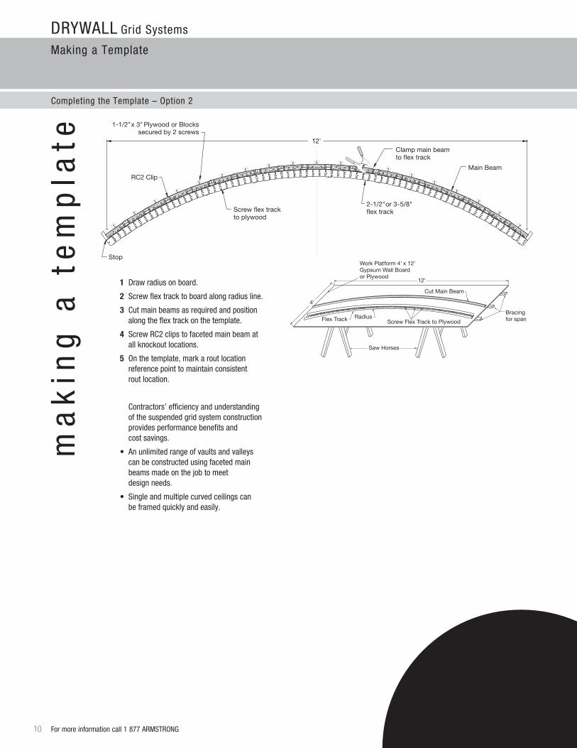
1 Draw radius on board.
2 Screw flex track to board along radius line.
3 Cut main beams as required and position along the flex track on the template.
4 Screw rC2 clips to faceted main beam at all knockout locations.
5 Onthetemplate,markaroutlocation reference point to maintain consistent rout location.
Contractors’ efficiency and understanding of the suspended grid system construction provides performance benefits and cost savings.
• Anunlimitedrangeofvaultsandvalleys can be constructed using faceted main beams made on the job to meet design needs.
• Singleandmultiplecurvedceilingscan be framed quickly and easily.
1-1/2" x 3" Plywood or Blockssecured by 2 screws
2-1/2" or 3-5/8" �ex track
12'
RC2 Clip
Screw �ex trackto plywood
Clamp main beamto �ex track
Stop
Main Beam
Bracing for span
Work Platform 4' x 12' Gypsum Wall Boardor Plywood
Saw Horses
Flex Track Radius
Cut Main Beam
Screw Flex Track to Plywood
4'
12'
For more information call 1 877 arMSTrONG 11
Drywall Grid Systems
working with Vaults
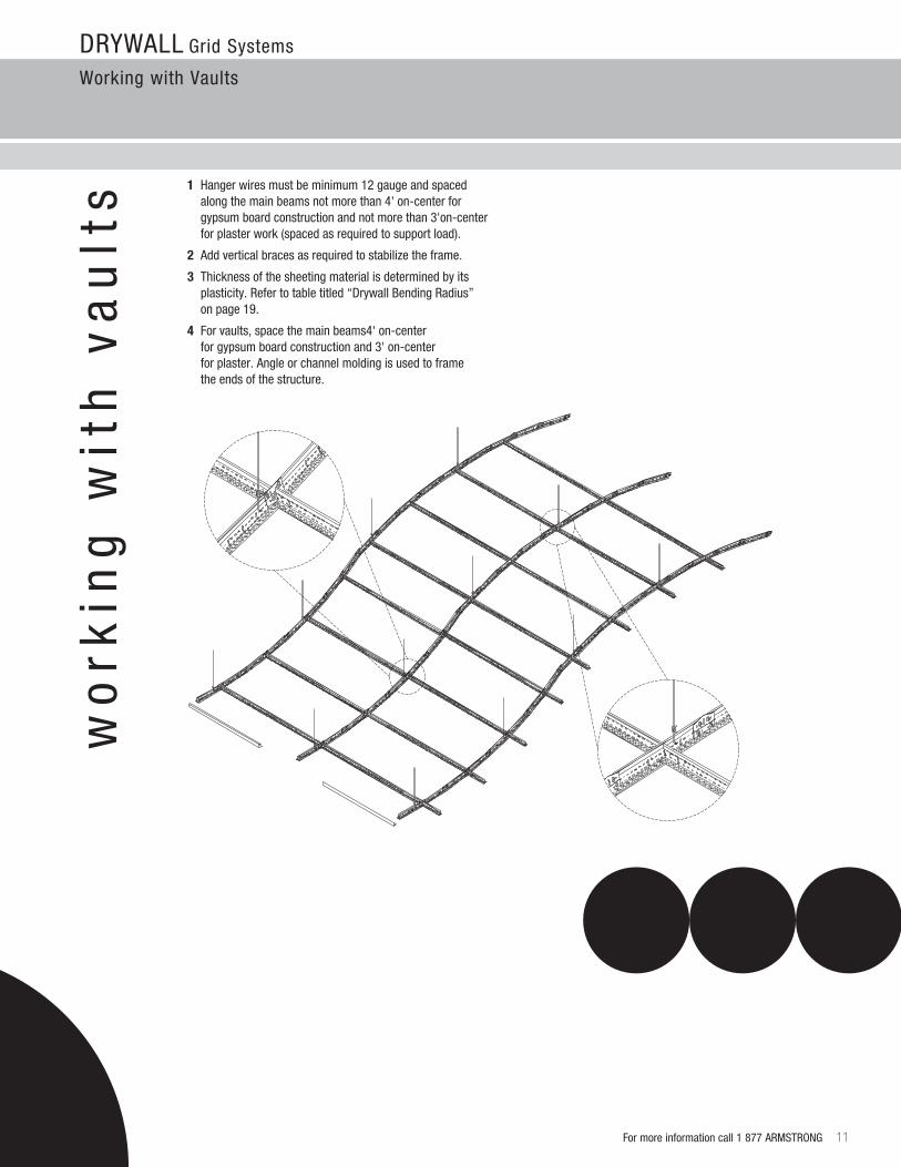
1 Hanger wires must be minimum 12 gauge and spaced along the main beams not more than 4' on-center for gypsum board construction and not more than 3'on-center for plaster work (spaced as required to support load).
2 Addverticalbracesasrequiredtostabilizetheframe.
3 Thickness of the sheeting material is determined by its plasticity. refer to table titled “Drywall Bending radius” on page 19.
4 Forvaults,spacethemainbeams4'on-center for gypsum board construction and 3' on-center for plaster. angle or channel molding is used to frame the ends of the structure.
wo
rkin
g w
ith
va
ult
s
· Combine valley and vault methods in a continuous ribbon.
· Pre-form main beams with cross tees between (spacing as required for gypsum wall board used)
· Splayed wires and stiffening braces as required
Hanger Wire
Vertical Brace
Main Beam
Cross Tee
DOME 66 FOOT RADIUS
Main Beam
RC2DW90C
Track or Channel Molding
Hanger Wire
arc
he
s
& b
arr
el
va
ult
sDrywall Grid Systems
arches and Barrel Vaults
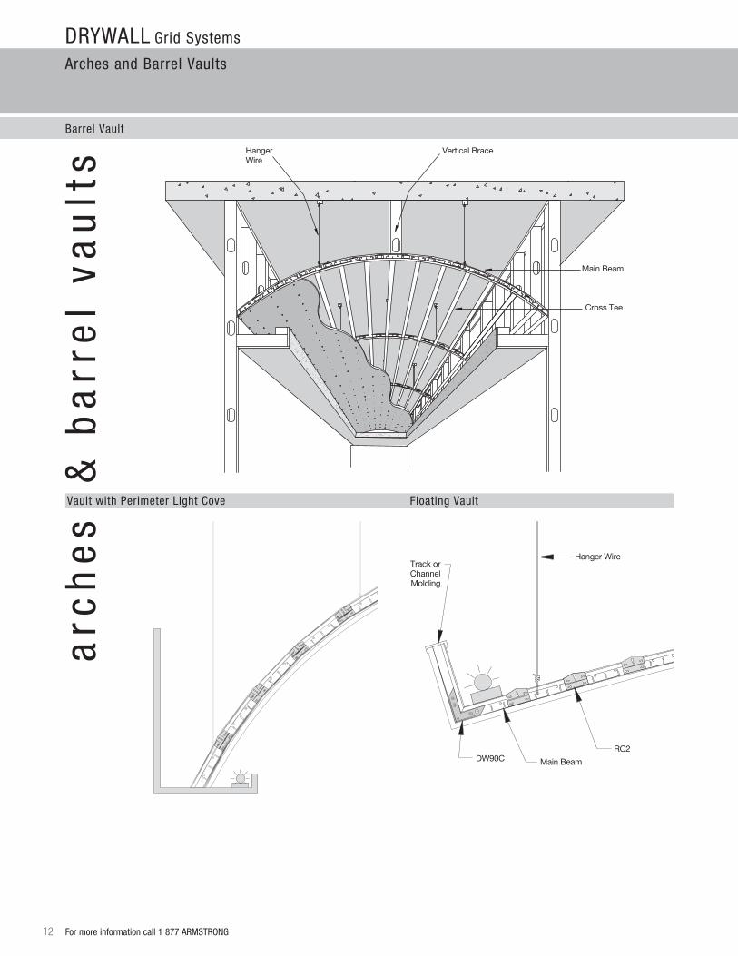
Barrel Vault
12 For more information call 1 877 arMSTrONG
Vault with Perimeter light Cove Floating Vault
CEILING CLOUD
RC2 Clip
8'-0"
1'-0" VerticalBrace
12' Radius 1 5/8" Track
GypsumWall Board
1'-0"
Gypsum Wall Board
Hanger Wire
RC2 Clip
Track or channel molding
Vertical Brace
45°
Gypsum Wall Board
Hanger Wire
Cross Tee
Main Beam
Track or channel molding
Upside Down Main Beam (for End Panel)
Gypsum Board
Angle Brace to Stabilize
Vertical Brace
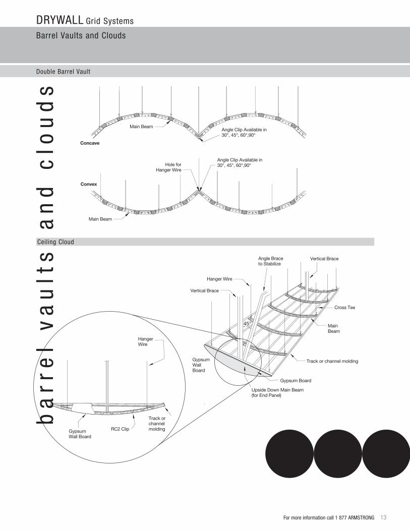
Concave
Convex
Main Beam
Main Beam
Hole for Hanger Wire
Angle Clip Available in 30°, 45°, 60°,90°
Angle Clip Available in 30°, 45°, 60°,90°
Drywall Grid Systems
Barrel Vaults and Clouds
Double Barrel Vault
For more information call 1 877 arMSTrONG 13
Ceiling Cloud
ba
rre
l v
au
lts
a
nd
clo
ud
s
Hanger Wires Spaced as RequiredVertical Brace
Cut & Screw Cross Tees
Cross Tee
Main Beam
Main Beam
Sheet Metal .040", 12" Dia.
Drywall Grid Systems
working with Domes
14 For more information call 1 877 arMSTrONG
do
me
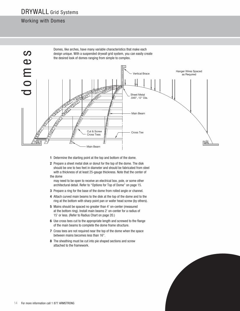
s Domes,likearches,havemanyvariablecharacteristicsthatmakeeach designunique.Withasuspendeddrywallgridsystem,youcaneasilycreatethe desired look of domes ranging from simple to complex.
1 Determine the starting point at the top and bottom of the dome.
2 Prepare a sheet metal disk or donut for the top of the dome. The disk should be one to two feet in diameter and should be fabricated from steel with a thickness of at least 25-gauge thickness. Note that the center of the dome mayneedtobeopentoreceiveanelectricalbox,pole,orsomeother architectural detail. refer to “Options for Top of Dome” on page 15.
3 Prepare a ring for the base of the dome from rolled angle or channel.
4 attach curved main beams to the disk at the top of the dome and to the ring at the bottom with sharp point pan or wafer head screw (by others).
5 Mains should be spaced no greater than 4' on-center (measured atthebottomring).Installmainbeams2'on-centerforaradiusof 15' or less. (refer to radius Chart on page 20.)
6 Use cross tees cut to the appropriate length and screwed to the flange of the main beams to complete the dome frame structure.
7 Cross tees are not required near the top of the dome when the space between mains becomes less than 16".
8 The sheathing must be cut into pie shaped sections and screw attached to the framework.
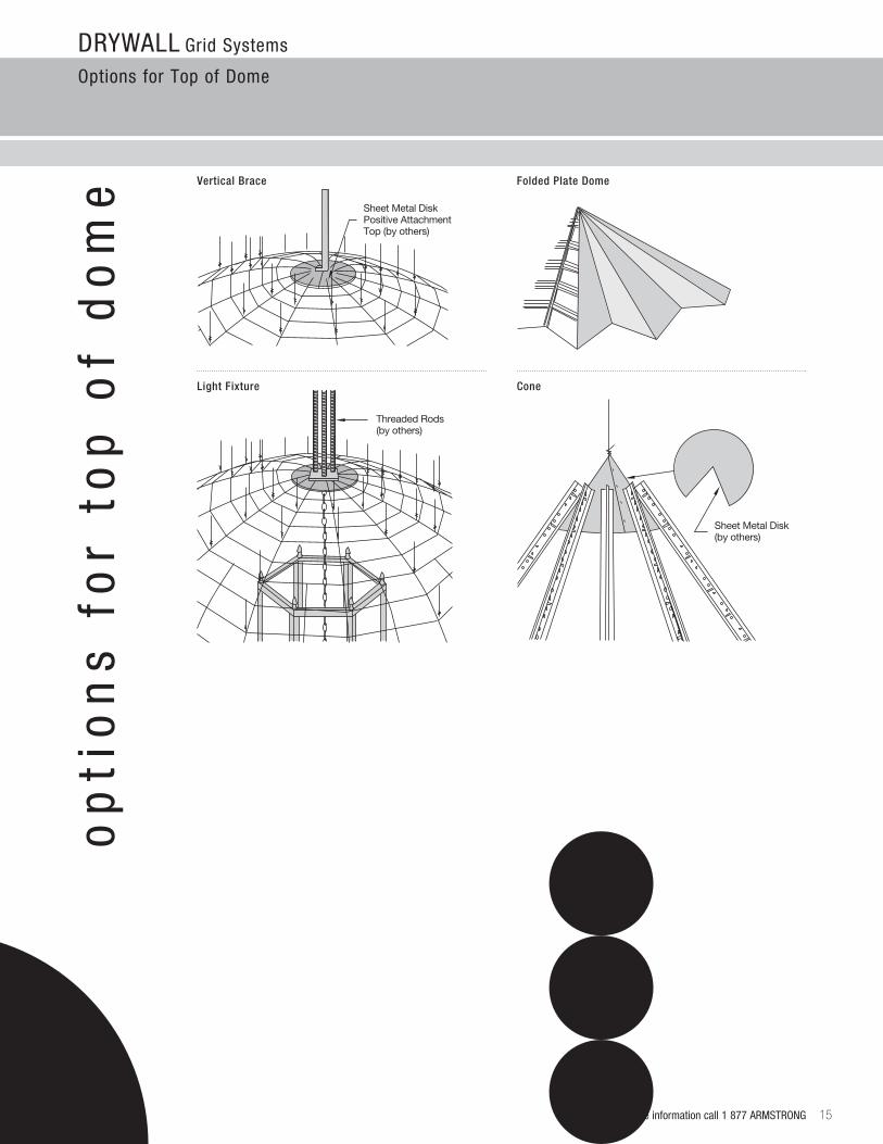
Sheet Metal Disk Positive Attachment Top (by others)
Sheet Metal Disk (by others)
Threaded Rods (by others)
Drywall Grid Systems
Options for Top of Dome
For more information call 1 877 arMSTrONG 15
op
tio
ns
fo
r to
p o
f d
om
e
Light Fixture
Vertical Brace Folded Plate Dome
Cone
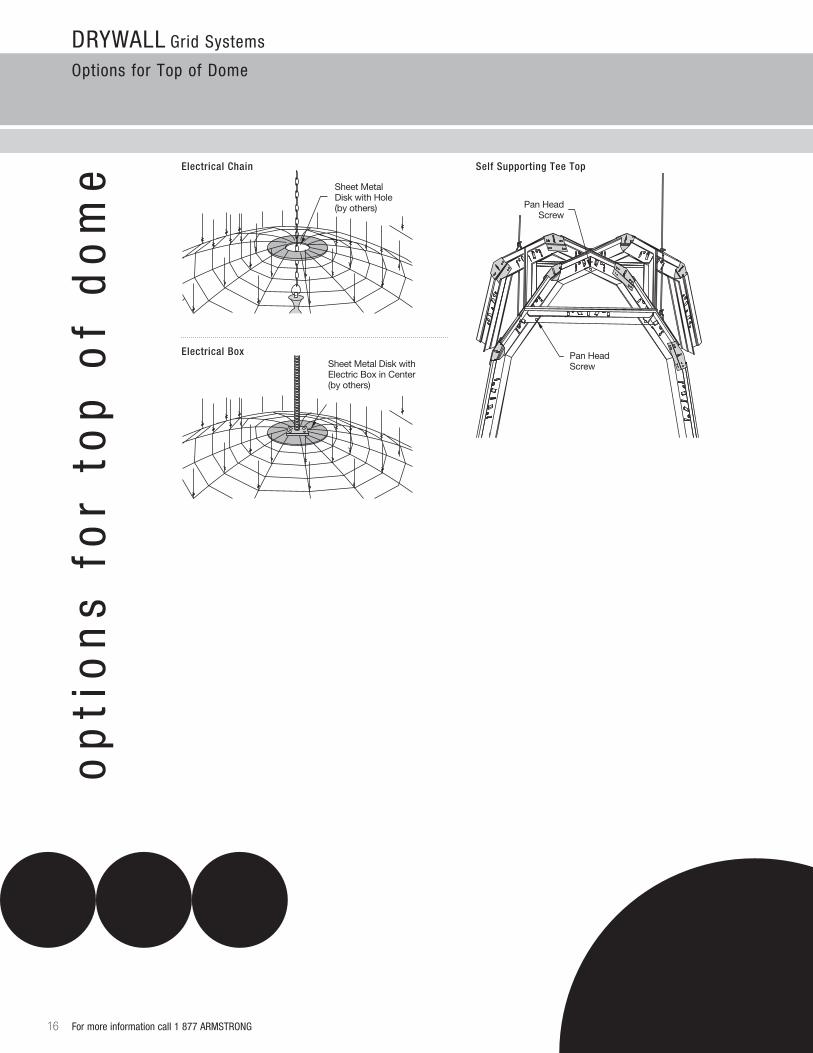
Sheet Metal Disk with Hole(by others)
Sheet Metal Disk with Electric Box in Center (by others)
Pan Head Screw
Pan Head Screw
Drywall Grid Systems
Options for Top of Dome
16 For more information call 1 877 arMSTrONG
op
tio
ns
fo
r to
p o
f d
om
e Electrical Chain Self Supporting Tee Top
Electrical Box
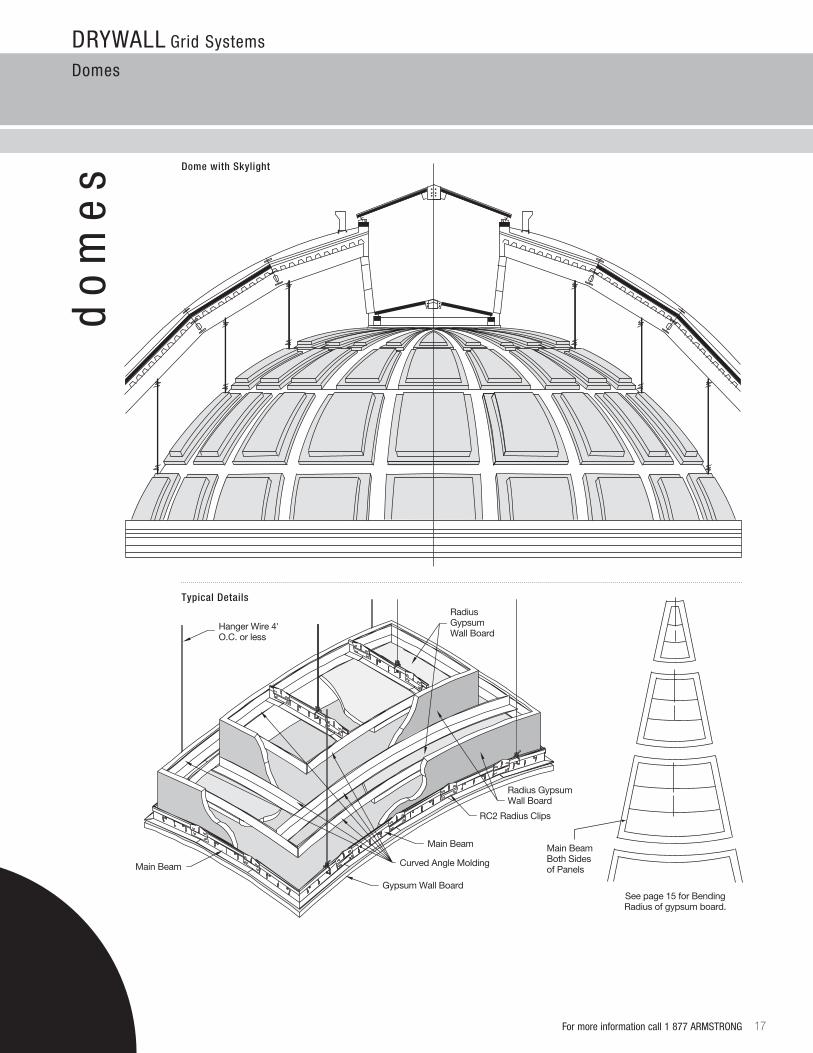
Main BeamBoth Sides of Panels
See page 15 for Bending Radius of gypsum board.
Main Beam
Main Beam
Hanger Wire 4' O.C. or less
Gypsum Wall Board
RadiusGypsum Wall Board
Curved Angle Molding
RC2 Radius Clips
Radius Gypsum Wall Board
Drywall Grid Systems
Domes
For more information call 1 877 arMSTrONG 17
do
me
s Dome with Skylight
Typical Details
Drywall Grid Systems
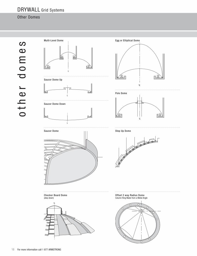
Other Domes
18 For more information call 1 877 arMSTrONG
oth
er
do
me
s
CL
CL
CL
CL
CL
44' Radius
CL
Main Beam
8"
RC-1 Radius Clip
ColumnAngle ClipOr Screw
Wire4' O.C.
#12 Wire
Column Ring Made From a Shiny 90 Metal Angle
1 5/8" Track 1 5/8"
Track
DOME 66 FOOT RADIUS
Cove Light
CL
CL
CL
CL
CL
CL
44' Radius
CL
Main Beam
8"
RC-1 Radius Clip
ColumnAngle ClipOr Screw
Wire4' O.C.
#12 Wire
Column Ring Made From a Shiny 90 Metal Angle
1 5/8" Track 1 5/8"
Track
DOME 66 FOOT RADIUS
Cove Light
CL
CL
CL
CL
CL
CL
44' Radius
CL
Main Beam
8"
RC-1 Radius Clip
ColumnAngle ClipOr Screw
Wire4' O.C.
#12 Wire
Column Ring Made From a Shiny 90 Metal Angle
1 5/8" Track 1 5/8"
Track
DOME 66 FOOT RADIUS
Cove Light
CL
CL
CL
CL
CL
CL
44' Radius
CL
Main Beam
8"
RC-1 Radius Clip
ColumnAngle ClipOr Screw
Wire4' O.C.
#12 Wire
Column Ring Made From a Shiny 90 Metal Angle
1 5/8" Track 1 5/8"
Track
DOME 66 FOOT RADIUS
Cove Light
CL
CL
CL
CL
CL
CL
44' Radius
CL
Main Beam
8"
RC-1 Radius Clip
ColumnAngle ClipOr Screw
Wire4' O.C.
#12 Wire
Column Ring Made From a Shiny 90 Metal Angle
1 5/8" Track 1 5/8"
Track
DOME 66 FOOT RADIUS
Cove Light
CL
CL
CL
CL
CL
CL
44' Radius
CL
Main Beam
8"
RC-1 Radius Clip
ColumnAngle ClipOr Screw
Wire4' O.C.
#12 Wire
Column Ring Made From a Shiny 90 Metal Angle
1 5/8" Track 1 5/8"
Track
DOME 66 FOOT RADIUS
Cove Light
CL
CL
CL
CL
CL
CL
44' Radius
CL
Main Beam
8"
RC-1 Radius Clip
ColumnAngle ClipOr Screw
Wire4' O.C.
#12 Wire
Column Ring Made From a Shiny 90 Metal Angle
1 5/8" Track 1 5/8"
Track
DOME 66 FOOT RADIUS
Cove Light
CL
Saucer Dome Up
Multi-Level Dome Egg or Elliptical Dome
Pole Dome
Saucer Dome Step Up Dome
Checker Board Dome(step down)
Offset 2 way Radius DomeColumn ring Made from a Metal angle
CL
CL
CL
CL
CL
44' Radius
CL
Main Beam
8"
RC-1 Radius Clip
ColumnAngle ClipOr Screw
Wire4' O.C.
#12 Wire
Column Ring Made From a Shiny 90 Metal Angle
1 5/8" Track 1 5/8"
Track
DOME 66 FOOT RADIUS
Cove Light
CL
Saucer Dome Down
Drywall Grid Systems
Finishing and Exterior application
For more information call 1 877 arMSTrONG 19
fin
ish
ing
& e
xter
ior
ap
pli
cati
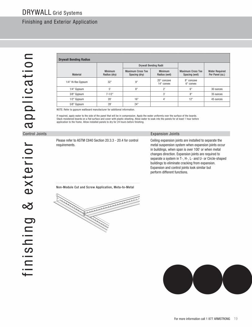
on Drywall Bending radius
MaterialMinimum
Radius (dry)
Drywall Bending Radii
Maximum Cross TeeSpacing (wet)
Water Required Per Panel (oz.)
Maximum Cross TeeSpacing (dry)
MinimumRadius (wet)
1/4" Hi-flex Gypsum 32" 9" 20" concave 14" convex
8" concave 6" convex
1/4" Gypsum 5' 8" 2' 6" 30 ounces
3/8" Gypsum 7-1/2" 3' 8" 35 ounces
1/2" Gypsum 20' 16" 4' 12" 45 ounces
5/8" Gypsum 28' 24"
NOTE: refer to gypsum wallboard manufacturer for additional information. Ifrequired,applywatertothesideofthepanelthatwillbeincompression.Applythewateruniformlyoverthesurfaceoftheboards. Stack moistened boards on a flat surface and cover with plastic sheeting. allow water to soak into the panels for at least 1 hour before application to the frame. allow installed panels to dry for 24 hours before finishing.
Control Joints Expansion Joints
Please refer to aSTM C840 Section 20.3.3 - 20.4 for control requirements.
Ceiling expansion joints are installed to separate the metal suspension system when expansion joints occur inbuildings,whenspanisover100'orwhenmetalchanges direction. Expansion joints are required to separateasysteminT-,H-,L-andu-orCircle-shaped buildings to eliminate cracking from expansion. Expansion and control joints look similar but perform different functions.
Non-Module Cut and Screw Application, Meta-to-Metal
Drywall Grid Systems
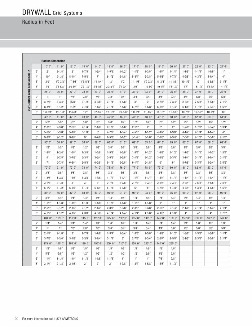
radius in Feet
20 For more information call 1 877 arMSTrONG
2' increments from
center line
radius Dimension
10' 0" 11' 0" 12' 0" 13' 0" 14' 0" 15' 0" 16' 0" 17' 0" 18' 0" 19' 0" 20' 0" 21' 0" 22' 0" 23' 0" 24' 0"
2' 2" 2-1/4" 2" 1-7/8" 1-3/4" 1-5/8" 1-1/2" 1-1/2" 1-3/8" 1-1/4" 1-1/4" 1-1/8" 1-1/8" 1-1/8" 1"
4' 10" 9-1/8" 8-1/4" 7-5/8" 7" 6-1/2" 6-1/8" 5-3/4" 5-3/8" 5-1/8" 4-7/8" 4-5/8" 4-3/8" 4-1/4" 4"
6' 2'0" 1'9-3/8" 1'7-3/8" 1'5-5/8" 1'4-1/4" 1'3" 1'2" 1'1-1/8" 1'0-3/8" 11-3/4" 11-1/8" 10-1/2" 10" 9-5/8" 9-1/8"
8' 4'0" 3'5-5/8" 3'0-3/4" 2'9-1/8" 2'6-1/8" 2'3-3/4" 2'1-3/4" 2'0" 1'10-1/2" 1'9-1/4" 1'8-1/8" 1'7" 1'6-1/8" 1'5-1/4" 1'4-1/2"
25' 0" 26' 0" 27' 0" 28' 0" 29' 0" 30' 0" 31' 0" 32' 0" 33' 0" 34' 0" 35' 0" 36' 0" 37' 0" 38' 0" 39' 0"
2' 1" 1" 7/8" 7/8" 7/8" 7/8" 3/4" 3/4" 3/4" 3/4" 3/4" 3/4" 5/8" 5/8" 5/8"
4' 3-7/8" 3-3/4" 35/8" 3-1/2" 3-3/8" 3-1/4" 3-1/8" 3" 3" 2-7/8" 2-3/4" 2-3/4" 2-5/8" 2-5/8" 2-1/2"
6' 8-3/4" 8-1/2" 81/2" 7-7/8" 7-1/2" 7-1/4" 7-1/8" 6-7/8" 6-5/8" 6-3/8" 6-1/4" 6-1/8" 5-7/8" 5-3/4" 5-5/8"
8' 1'3-3/4" 1'3-1/8" 1'25/8" 1'2" 1'2-1/2" 1'1-1/8" 1'0-5/8" 1'0-1/4" 11-1/2" 11-1/2" 11-1/8" 10-7/8" 10-1/2" 10-1/4" 10"
40' 0" 41' 0" 42' 0" 43' 0" 44' 0" 45' 0" 46' 0" 47' 0" 48' 0" 49' 0" 50' 0" 51' 0" 52' 0" 53' 0" 54' 0"
2' 5/8" 5/8" 5/8" 5/8" 5/8" 5/8" 1/2" 1/2" 1/2" 1/2" 1/2" 1/2" 1/2" 1/2" 1/2"
4' 2-3/8" 2-3/8" 2-3/8" 2-1/4" 2-1/8" 2-1/8" 2-1/8" 2-1/8" 2" 2" 2" 1-7/8" 1-7/8" 1-3/4" 1-3/4"
6' 5-1/2" 5-3/8" 5-1/4" 5-1/8" 5" 4-7/8" 4-3/4" 4-5/8" 4-1/2" 4-1/2" 4-3/8" 4-1/4" 4-1/4" 4-1/4" 4"
8' 9-3/4" 9-1/2" 9-1/4" 9" 8-7/8" 8-5/8" 8-1/2" 8-1/4 “ 8-1/8" 7-7/8" 7-3/4" 7-5/8" 7-1/2" 7-3/8" 7-1/8"
55' 0" 56' 0" 57' 0" 58' 0" 59' 0" 60' 0" 61' 0" 62' 0" 63' 0" 64' 0" 65' 0" 66' 0" 67' 0" 68' 0" 69' 0"
2' 1/2" 1/2" 1/2" 1/2" 1/2" 3/8" 3/8" 3/8" 3/8" 3/8" 3/8" 3/8" 3/8" 3/8" 3/8"
4' 1-3/4" 1-3/4" 1-3/4" 1-3/4" 1-5/8" 1-5/8" 1-5/8" 1-5/8" 1-1/2" 1-1/2" 1-1/2" 1-1/2" 1-1/2" 1-1/2" 1-3/8"
6' 4" 3-7/8" 3-7/8" 3-3/4" 3-3/4" 3-5/8" 3-5/8" 3-1/2" 3-1/2" 3-3/8" 3-3/8" 3-1/4" 3-1/4" 3-1/4" 3-1/8"
8' 7" 6-7/8" 6-3/4" 6-5/8" 6-5/8" 6-1/2" 6-3/8" 6-1/4" 6-1/8" 6" 6" 5-7/8" 5-3/4" 5-3/4" 5-5/8"
70' 0" 71' 0" 72' 0" 73' 0" 74' 0" 75' 0" 76' 0" 77' 0" 78' 0" 79' 0" 80' 0" 81' 0" 82' 0" 83' 0" 84' 0"
2' 3/8" 3/8" 3/8" 3/8" 3/8" 3/8" 3/8" 3/8" 3/8" 3/8" 3/8" 3/8" 3/8" 3/8" 3/8"
4' 1-3/8" 1-3/8" 1-3/8" 1-3/8" 1-3/8" 1-1/4" 1-1/4" 1-1/4" 1-1/4" 1-1/4" 1-1/4" 1-1/4" 1-1/4" 1-1/4" 1-1/8"
6' 3-1/8" 3-1/8" 3" 3" 3" 2-7/8" 2-7/8" 2-7/8" 2-3/4" 2-3/4" 2-3/4" 2-3/4" 2-5/8" 2-5/8" 2-5/8"
8' 5-1/2" 5-1/2" 5-3/8" 5-1/4" 5-1/4" 5-1/8" 5-1/8" 5" 5" 4-7/8" 4-7/8" 4-3/4" 4-3/4" 4-5/8" 4-5/8"
85' 0" 86' 0" 87' 0" 88' 0" 89' 0" 90' 0" 91' 0" 92' 0" 93' 0" 94' 0" 95' 0" 96' 0" 97' 0" 98' 0" 99' 0"
2' 3/8" 1/4" 1/4" 1/4" 1/4" 1/4" 1/4" 1/4" 1/4" 1/4" 1/4" 1/4" 1/4" 1/4" 1/4"
4' 1-1/8" 1-1/8" 1-1/8" 1-1/8" 1-1/8" 1-1/8" 1-1/8" 1-1/8" 1-1/8" 1" 1" 1" 1" 1" 1"
6' 2-5/8" 2-1/2" 2-1/2" 2-1/2" 2-1/2" 2-3/8" 2-3/8" 2-3/8" 2-3/8" 2-3/8" 2-1/4" 2-1/4" 2-1/4" 2-1/4" 2-1/4"
8' 4-1/2" 4-1/2" 4-1/2" 4-3/8" 4-3/8" 4-1/4" 4-1/4" 4-1/4" 4-1/8" 4-1/8" 4-1/8" 4" 4" 4" 3-7/8"
100' 0" 105' 0" 110' 0" 115' 0" 120' 0" 125' 0" 130' 0" 135' 0" 140' 0" 145' 0" 150' 0" 155' 0" 160' 0" 165' 0" 170' 0"
2' 1/4" 1/4" 1/4" 1/4" 1/4" 1/4" 1/4" 1/4" 1/4" 1/4" 1/4" 1/4" 1/8" 1/8" 1/8"
4' 1" 1" 7/8" 7/8" 7/8" 3/4" 3/4" 3/4" 3/4" 3/4" 5/8" 5/8" 5/8" 5/8" 5/8"
6' 2-1/4" 2-1/8" 2" 1-7/8" 1-7/8" 1-3/4" 1-3/4" 1-5/8" 1-5/8" 1-1/2" 1-1/2" 1-3/8" 1-3/8" 1-3/8" 1-1/4"
8' 3-7/8" 3-3/4" 3-1/2" 3-3/8" 3-1/4" 3-1/8" 3" 2-7/8" 2-3/4" 2-3/4" 2-5/8" 2-1/2" 2-3/8" 2-3/8" 2-1/4"
175' 0" 180' 0" 185' 0" 190' 0" 195' 0" 200' 0" 210' 0" 220' 0" 230' 0" 240' 0" 250' 0"
2' 1/8" 1/8" 1/8" 1/8" 1/8" 1/8" 1/8" 1/8" 1/8" 1/8" 1/8"
4' 5/8" 5/8" 1/2" 1/2" 1/2" 1/2" 1/2" 1/2" 3/8" 3/8" 3/8"
6' 1-1/4" 1-1/4" 1-1/4" 1-1/8" 1-1/8" 1-1/8" 1" 1" 1" 7/8" 7/8"
8' 2-1/4" 2-1/8" 2-1/8" 2" 2" 2" 1-7/8" 1-3/4" 1-5/8" 1-5/8" 1-1/2"
Drywall Grid Systems
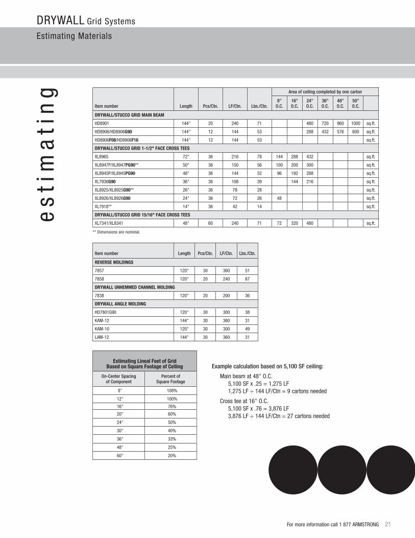
Estimating Materials
For more information call 1 877 arMSTrONG 21
es
tim
ati
ng
estimating lineal Feet of Grid Based on Square Footage of ceiling
On-Center Spacing of Component
Percent of Square Footage
8" 108%
12" 100%
16" 76%
20" 60%
24" 50%
30" 40%
36" 33%
48" 25%
60" 20%
Example calculation based on 5,100 SF ceiling:
Main beam at 48" O.C. 5,100SFx.25=1,275LF 1,275LF÷144LF/Ctn=9cartonsneeded
Cross tee at 16" O.C. 5,100SFx.76=3,876LF 3,876LF÷144LF/Ctn=27cartonsneeded
** Dimensions are nominal.
Item number Length Pcs/Ctn. LF/Ctn. Lbs./Ctn.
Area of ceiling completed by one carton
8"O.C.
16"O.C.
24"O.C.
36"O.C.
48"O.C.
50"O.C.
Drywall/STuccO GriD Main BeaM
HD8901 144" 20 240 71 480 720 960 1000 sq.ft.
HD8906/HD8906G90 144" 12 144 53 288 432 576 600 sq.ft.
HD8906F08/HD8906F16 144" 12 144 53 sq.ft.
Drywall/STuccO GriD 1-1/2" Face crOSS TeeS
Xl8965 72" 36 216 78 144 288 432 sq.ft.
Xl8947P/Xl8947PG90** 50" 36 150 56 100 200 300 sq.ft.
Xl8945P/Xl8945PG90 48" 36 144 52 96 192 288 sq.ft.
Xl7936G90 36" 36 108 39 144 216 sq.ft.
Xl8925/Xl8925G90** 26" 36 78 28 sq.ft.
Xl8926/Xl8926G90 24" 36 72 26 48 sq.ft.
Xl7918** 14" 36 42 14 sq.ft.
Drywall/STuccO GriD 15/16" Face crOSS TeeS
Xl7341/Xl8341 48" 60 240 71 72 320 480 sq.ft.
Item number Length Pcs/Ctn. LF/Ctn. Lbs./Ctn.
reVerSe MOlDinGS
7857 120" 30 360 51
7858 120" 20 240 67
Drywall unheMMeD channel MOlDinG
7838 120" 20 200 36
Drywall anGle MOlDinG
HD7801G90 120" 30 300 38
KaM-12 144" 30 360 31
KaM-10 120" 30 300 49
laM-12 144" 30 360 31

TechlineSM / 1 877 arMSTrONG
1 877 276 7876
armstrong.com/drywallgrid
BPCS-3540-812
AlltrademarksusedhereinarethepropertyofAWILicensingCompanyand/oritsaffiliates©2012AWILicensingCompany • PrintedintheunitedStatesofAmerica
c e i l i n G S y s t e m s
1 8 7 7 A R M S T R O N G ( 1 8 7 7 2 7 6 7 8 7 6 )
•NameofyourInnerCircleContractoror Gold Circle Distributor or Sales representative
•CustomerServiceRepresentatives 7:30a.m.to5:00p.m.EST,MondaythroughFriday
•Techline – Technical information 8:00a.m.to5:30p.m.EST,MondaythroughFriday FaX 1-800-572-8324 or email: [email protected]
•Productliteratureandsamples Express service or regular delivery
•request a personal copy of the armstrong Ceiling Systems catalog
a r m s t r o n g . c o m / d r y w a l l g r i d
•Latestproductandprogramnews
•Realtimeselectionandtechnicalinformation
•Contacts–reps,wheretobuy,howtoinstall
•Submittalpages
•Literatureandsamplesinformation
•CADrenderings
These drawings show typical conditions in which the armstrong product depicted is installed. They are not a substitute for an architect’s or engineer’s plan and do not reflect the unique requirements oflocalbuildingcodes,laws,statutes,ordinances,rules and regulations (legal requirements) that may be applicable for a particular installation.
armstrong does not warrant and assumes no liability for the accuracy or completeness of the drawings for a particular installation or their fitness for a particular purpose. The user is advised to consult with a duly licensed architect or engineer in the particular locale of the installation to assure compliance with all legal requirements.
armstrong is not licensed to provide professional architecture or engineering design services.
Engineering data included provided by outside engineering company.
For additional information regarding armstrong Drywall Systems visit armstrong.com/drywallgrid or reference:
CS-3950 QuikStix Drywall wall liner System
CS-3542 Synthetic Stucco Grid Systems
CS-3541 Stucco/Plaster Grid Systems
CS-3539 Drywall Grid Systems for Flat applications
D r y w a l l G r i d S y s t e m s