CEILING MOUNT FAN COIL UNIT - SurnaThe Surna ceiling mount fan coil uses a chilled water system to...
20
CEILING MOUNT FAN COIL UNIT OPERATING AND MAINTENANCE MANUAL surna.com Models: 2-18-01, 2-18,02, 2-36-01, 2-36-02, 2-60-02 August 2017
Transcript of CEILING MOUNT FAN COIL UNIT - SurnaThe Surna ceiling mount fan coil uses a chilled water system to...

CEILING MOUNT FAN COIL UNITOPERATING AND MAINTENANCE MANUAL
s u r n a . c o m
Models: 2-18-01, 2-18,02, 2-36-01, 2-36-02, 2-60-02
August 2017


TABLE OF CONTENTS
Specifications 4
Technical Description 5
Warnings 6
Warranty Information 8
Installation Instructions 10
Routine Maintenance 19
3

SPECIFICATIONS
PHYSICAL1.5 TON2-18-01
1.5 TON2-18-02
3 TON2-36-01
3 TON2-36-02
5 TON2-60-02
Length 37.72 in 49.68 in 56.10 in
Width 21.65 in 20 in
Height 10.25 in 13.78 in
Weight 68.20 lbs 83.60 lbs 72.80 lbs
Water Inlet 1/2 in FNPT 3/4 in FNPT
Water Outlet 1/2 in FNPT 1/2 in FNPT* 1/2 in FNPT 1/2 in FNPT* 3/4 in FNPT
Condensation Drain 3/4 in NPT 3/4 in SLIP
ELECTRICAL
Electric Heat None 3kW None 5kW None
Volts - Phase 208/230V Single Phase
Minimum Circuit Ampacity (MCA) 1.48A 20.08A 2.26A 32.84A 3.40A
Maximum Overcurrent Protection (MOP)
3A 20A 5A 35A 8A
PERFORMANCE & MECHANICAL
Nominal Cooling Capacity 1.5 Tons 1.5 Tons 3 Tons 3 Tons 5 Tons
2-18-01, 2-18-02
2-36-01, 2-36-02
2-60-02
0.000.501.001.502.002.503.003.504.004.505.00
1 2 3 4 5 6
Co
olin
g P
erfo
rman
ce (T
R)
Nominal Size (TR)
Cooling Performance at 80°F, 50%RH
Total Cooling
Sensible Cooling
Latent Cooling
WATER OUTLET
BALL VALVE
1/2" NPT
1/2" FNPT
1/2" FNPT*Unit includes necessary 1/2” motorized ball valve
4

The Surna ceiling mount fan coil uses a chilled
water system to remove heat and moisture from
the environment. The water/glycol mixture flows
from the supply plumbing through the heat
exchanger/coil, where warm air is passed across the
heat exchanger via the fan. As the fan pulls warm,
humid air from the room and passes it across the
copper heat exchanger, heat is transferred from
the incoming air to the water/glycol solution. The
large temperature difference between the hot air
and chilled water leads to condensation, reducing
relative humidity. The water/glycol mix is then
circulated from the heat exchanger back into the
return manifold and is pumped through the chillers
to reject heat outside.
Figure 1 - Ceiling mount fan coil
TECHNICAL DESCRIPTION
5

DEFINITIONS
CAUTION: Risk of minor/moderate injury if precaution not taken.
WARNING: Risk of death/serious injury if warning isn’t heeded.
DANGER: Risk of death/serious injury if danger isn’t avoided.
SAFET Y SYMBOLS USED
CAUTION: Important information, read the provided instructions carefully
WARNING: Potential electric shock hazard
WARNING: High voltage
WARNING: Cut/Crush hazard
Protective earth connection
Action prohibited
FAN COIL SAFET Y GUIDE
Please read the information in this document carefully prior to attempting the installation, operation and/or servicing of the fan coil. This document contains all information required to install and operate the Surna ceiling mount fan coil unit. Failure to follow the directions provided herein may impair the safeties provided and could cause damage to the fan coil equipment and/or accessory equipment, damage to building facilities, and/or cause serious injury or death to the operator. Please adhere to all applicable safety guideline requirements in this document and all applicable electrical and mechanical jurisdictional codes.
Prior to providing power to the equipment, inspect the area for water spills, which may present a shock hazard to the user. Take extra care to mount accessory electrical equipment away from areas regularly exposed to water and provide secure wire and cable routing to protect personnel from shock hazards.
Only operate the equipment with an appropriately sized breaker in place and wire sizes with adequate current carrying capacity. Consult with an electrician before attempting electrical installation.
Using Surna fan coils in a manner not described in this manual may void its warranty and any safeties provided herein.
WARNINGS
6

After installation and maintenance activities, observe the system operation to verify that the fan coil is operating normally before leaving equipment to operate unattended.
Only use Surna supplied or recommended equipment with the Surna ceiling mount fan coil.
CAUTION: Care must be taken when handling sheet metal. Sheet metal parts have sharp edges and could cause injury.
The components of this fan coil have been inspected at the factory and readied for shipment. Upon receiving the shipment, a visual inspection of the packaging must be performed.
Care must be taken to ensure the structural integrity of the supporting members when mounting these devices. Verify that the load bearing capacity of any mounting surface is rated for the load of the fan coil.
DO NOT use ethylene glycol with this system. Only propylene glycol is to be used.
Adequate clearance shall be provided around the unit for regular servicing. After installation, service and maintenance personnel shall be able to access the power supply, coil connections and condensate drain.
This unit must be connected to a protective earthing system prior to operation. DO NOT remove the grounded connection while power is being supplied to the Surna fan coil. Doing so presents an electric shock hazard to users and service personnel.
7

Equipment manufactured by Surna (“Company”), the
warranty shall exist for a period of twelve (12) months
from initial start-up or eighteen (18) months from date
of shipment, whichever period is shorter, against failure
due to defects in material and/or manufacturing and
warranted to the capacities and ratings set forth in
Company’s catalogs and bulletins (“Warranty”).
Equipment, material, and/or parts that are not
manufactured by Company are not warranted by
Company and carry such warranties as may be extended
by the respective manufacturer.
Exclusions from this Warranty include damage or failure
arising from: wear and tear; corrosion, erosion,
deterioration; modifications made by others to the
Equipment; repairs or alterations by a party other than
Company that adversely affect the stability or reliability
of the Equipment; vandalism; neglect; accident; adverse
weather or environmental conditions; abuse or improper
use; improper installation; commissioning by a party
other than Company; unusual physical, electrical or
mechanical stress; lack of proper startup or maintenance
as recommended by Company; operation with any
accessory, equipment or part not specifically approved
by Company; and/or refrigerant not recommended or
supplied by Company.
Company shall not be obligated to pay for the cost of
lost refrigerant or lost product or any other direct,
indirect, or consequential damages. Company’s
obligations and liabilities under this Warranty are limited
to furnishing replacement equipment or parts, at its
option, FCA (Incoterms 2000) factory or warehouse
(f.o.b. factory or warehouse for US domestic purposes) at
Company-designated shipping point, freight allowed to
Company’s warranty agent’s stock location, for all
non-conforming Company manufactured Equipment
which have been returned by Customer to Company.
Returns must have prior written approval by Company
and are subject to restocking and replacement charges
where applicable.
No warranty liability whatsoever shall attach to Company
until Customer’s complete order has been paid for in full
and Company’s liability under this Warranty shall be
limited to the purchase price of the Equipment shown to
be defective.
Additional warranty and service protection is available
on an extra-cost basis and must be in writing and
agreed to by an authorized signatory of the Company.
The warranty excludes: (a) labor, transportation and
related costs incurred by the Dealer or Customer; (b)
re-installation costs of repaired equipment; (c) re-
installation costs of replacement equipment; (d) removal
costs of equipment; (e) consequential damages of any
kind; and, (f) reimbursement for loss caused by
interruption of service.
EQUIPMENT MANUFACTURED BY COMPANY THAT
INCLUDES A REQUIRED START-UP AND SOLD IN
NORTH AMERICA WILL NOT BE WARRANTED BY
COMPANY UNLESS COMPANY OR ITS AUTHORIZED
WARRANTY INFORMATION
8

AGENT PERFORMS THE EQUIPMENT STARTUP.
COMPANY MAKES NO REPRESENTATION OR
WARRANTY, EXPRESS OR IMPLIED, REGARDING
PREVENTION OF MOLD/MOULD, FUNGUS, BACTERIA,
MICROBIAL GROWTH, OR ANY OTHER
CONTAMINATES.
EXCEPT FOR COMPANY’S WARRANTY EXPRESSLY
SET FORTH HEREIN, COMPANY DOES NOT MAKE,
AND HEREBY EXPRESSLY DISCLAIMS, ANY
WARRANTIES, EXPRESS OR IMPLIED CONCERNING
ITS PRODUCTS, EQUIPMENT OR SERVICES,
INCLUDING, WITHOUT LIMITATION, ANY WARRANTY
OF DESIGN, MERCHANTABILITY OR OF FITNESS FOR
A PARTICULAR PURPOSE, OR OTHERS THAT ARE
ALLEGED TO ARISE FROM COURSE OF DEALING OR
TRADE.
FAN COIL ORDER
Below is a list of all parts provided with each Surna
ceiling mount fan coil. The following are included with
the order (quantities are dependent on individual order).
1. Surna ceiling mount fan coil
2. Surna ceiling mount fan coil manual
3. Flowmeter (Dwyer VFC II-143)
9

MECHANICAL
This fan coil unit is designed to be mounted in a horizontal configuration only. The weight information for each model can be found in the specifications section of this document; take care to ensure the supporting members are rated to support the fan coil load. When installing, clearances must be provided as a provision to allow maintenance/service of the unit. Additionally, clearance around the unit increases performance by allowing airflow.
General Installation guidelines:
1. Leave a minimum of 36 inches (91.5 cm) of horizontal clearance on intake side of the unit and 72 inches (182.8 cm) on discharge side.
2. Do not point the intake/discharge of the unit at the discharge/intake of another nearby fan coil or dehumidifier.
3. Do not mount fan coil using a unistrut trapeze. Directly mount the unit with threaded rod through the four top plate mounting holes, as shown in figure 2.
NOTE: Extend unistrut beyond mounting holes for more precise slope adjustments.
4. Mount sloped to drain, 0.25-0.5 in/foot. Do not exceed 5 degrees.
RETURN AND SUPPLY AIR CONNECTIONS
Surna fan cois are supplied and operated without air
supply or return ducting. The unit is supplied without
air filtration components. Incoming air filtration is not
required; however, the condensing coils must be cleaned
on a quarterly basis. Failure to clean condensing coils
periodically can result in reduced cooling efficiency. See
the routine maintenance section of this manual for the
recommended cleaning schedule.
INSTALLATION INSTRUCTIONS
1 0

WIRING
WARNING: Turn off the breaker until all electrical connections are made.
WARNING: This unit must be connected to a protective grounding system.
All wiring shall comply with local and national codes. Before attempting system
installation, verify that the electrical system and wiring are adequate for supplying
the required ampacity to the fan coil unit (see specifications section of this
document). High and low voltage terminal blocks are provided in the unit’s
electrical panel. Reference figures 3 - 5 for wiring diagrams. Making improper
electrical connections could cause damage to the equipment or harm to servicing
personnel. Never perform electrical work unless properly trained and licensed and
aware of relevant electrical codes and requirements.
There are different wiring configurations depending on selected options, but
all units will include high and low voltage terminals as well as a ground terminal.
Usual locations are shown in figure 6.
1 1

PLUMBING The fan coil has a dedicated water inlet connection and
a dedicated water outlet connection. When installing
these connections, verify these connections are not
reversed or the unit will not operate properly. Refer to
the specifications section of this document for water
connection sizes and types. Proper insulation is needed
for the water lines in accordance with local and national
building codes.
The fan coil has one condensate drain connection on
either side of the drain pan for either left or right hand
drain connection. The drain connection not being used
must be capped off by the installing contractor. The
middle drain connection is the safety condensate drain
connection. Ensure that all condensate drain lines have
at least 1/4 inch (6.35 mm) of fall per foot for proper
drainage. Install P-Traps to avoid air lock.
The fan coil also comes with a manual air bleed and a
manual coil drain fitting. They are located on the same
side as the supply and return water line connections.
The water supply line is connected to the coil connection
furthest away from the fans. The water return line is
connected to the coil connection closest to the fans.
Ensure that both the supply and return water lines are
insulated to prevent them from sweating.
Following plumbing installation, the system should be
checked for leaks prior to unattended operation of the
system.
IMPORTANT PLUMBING TIPS
1. All hydronic piping should be schedule 80 PVC or
schedule 40 black iron pipe. All condensate piping
should be schedule 40 PVC.
2. Manifold size will vary depending on size and quantity
of equipment connected to it. Piping should be sized
based on total flow required for all equipment being
supplied by it.
3. Return manifold should be equivalent to supply
manifold.
4. Install isolation valves on all supply and return
manifolds near each fan coil unit inlet/outlet for ease
of service. Isolation valve on fan coil unit outlet may be
used to throttle flow during system balancing.
5. Install a hose end drain valve near pump inlet and
upstream of wye strainer for system fill and flush.
6. Use long radius elbow fittings whenever possible to
reduce flow restrictions.
7. Insulate all condensate, supply and return piping to
avoid condensation outside of equipment. UV
protective insulation with aluminum jacket should be
used on all outdoor piping.
8. Fan coil unit flow rate requirement is 2.5 GPM per
nominal ton to operate at maximum efficiency. For
example, the 5-Ton fan coil unit requires 12.5 GPM.
9. Fan coil unit inlet/outlet connections are either ½ inch
(1.27 cm) or ¾ inch (1.90 cm) FNPT depending on size
of unit. Downsize PVC as close to inlet/outlet as
possible to reduce flow restrictions.
1 2

10. The fan coil unit is marked with “IN” and “OUT” water connections for proper direction
of flow. The unit will not operate properly if these connections are reversed.
11. Chiller temperature should be set at 55°F (13°C) to start. Adjust the temperature up or
down depending on specific circumstances. Do not adjust the chillers set-
point temperature below 45°F (7°C).
12. Colored, 95% corrosion inhibited USP grade propylene glycol and dionized or distilled
water should be utilized at a minimum of 25%/75% (glycol/water) solution. This
prohibits freezing and acts as a system lubricant/anti-corrosive to keep the chiller
and fan coils working at peak performance. DO NOT use ethylene glycol (standard car
antifreeze). Percentage of glycol will vary depending on location and should be
approved by Surna.
13. Once all plumbing is complete, run clean water through the system to flush out all
residue and check for leaks. Run system for approximately 5 minutes and then drain
water from the system. Correct any leaks and clean wye strainer. Lastly, refill with
prescribed glycol/water mixture (presented in #12 above). When complete, turn on
system and top off as necessary.
14. Install air vents at high points of all supply and return lines to reduce air in system.
Install drain valves at all low points and slope piping to low points for service drainage.
1 31 3

UNISTRUT GRID
3/8” All-Thread
Hex Nut (TYP)
Lock Washer (TYP)
Crush Washer (TYP)
Figure 2 - Mounting detail for ceiling mount fan coil
MOUNTING DETAIL
1 4
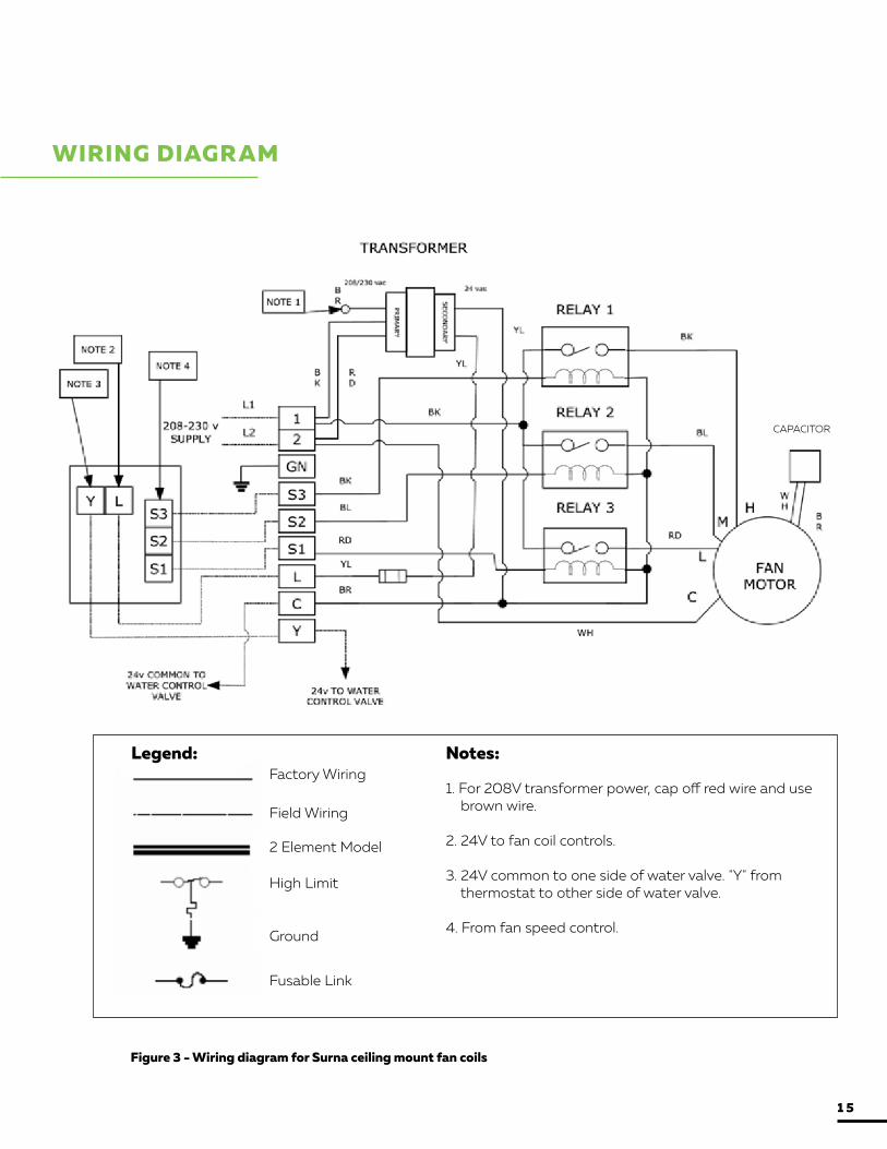
WIRING DIAGRAM
Legend:Factory Wiring
Field Wiring
2 Element Model
High Limit
Ground
Fusable Link
Notes:
1. For 208V transformer power, cap off red wire and use brown wire.
2. 24V to fan coil controls.
3. 24V common to one side of water valve. "Y" from thermostat to other side of water valve.
4. From fan speed control.
Figure 3 - Wiring diagram for Surna ceiling mount fan coils
CAPACITOR
1 5

3KW HEAT KIT WIRING DIAGRAM
Figure 4 - Wiring diagram for ceiling mount fan coil with optional 3kW heat kit
Legend:Factory Wiring
Field Wiring
2 Element Model
High Limit
Ground
Fusable Link
Notes:
1. For 208V transformer power, cap off red wire and use brown wire.
2. 24V to fan coil controls.
3. 24V common to one side of water valve. "Y" from thermostat to other side of water valve.
4. From fan speed control.
CAPACITOR
1 6

5KW HEAT KIT WIRING DIAGRAM
Figure 5 - Wiring diagram for Surna ceiling mount fan coils with optional 5kW heat kit
Legend:Factory Wiring
Field Wiring
2 Element Model
High Limit
Ground
Fusable Link
Notes:
1. For 208V transformer power, cap off red wire and use brown wire.
2. 24V to fan coil controls.
3. 24V common to one side of water valve. "Y" from thermostat to other side of water valve.
4. From fan speed control.
CAPACITOR
1 7

Figure 6 - Wiring installation connections- typical terminal block locations
INSTALLATION CONNECTIONS
A Low voltage terminal block
B High voltage terminal block
C Grounding terminal
Figure 7 - Plumbing installation connections
A Air vent B Water supply C Water return
D Coil drain E Condensate drain F Secondary condensate drain
F
A
B
C
DE
ABC
ACB
1 8

This product is designed to provide many years of dependable, trouble free comfort when properly maintained. Proper maintenance will consist of routine filter cleanings/changes, bi-annual check-ups that include (but are not limited to) filter inspections and electric heater inspections/cleaning of the internal electrical and heat transfer components by a qualified service technician. Failure to provide periodic check-ups and cleaning can result in excessive operating cost and/or equipment failure.
CONTACT US
Contact Surna via email at [email protected] or via phone at 303.993.5271.
ROUTINE MAINTENANCE
Task Description for Fan-coil Units Frequency*
Check condensate lines are draining and free of blockage and/or debris. Treat drains and remove any foreign debris.
Q1, SA, Q3, A
Verify condensate line meets minimum insulation requirements. Verify insulation is free of excessive moisture buildup. Advise on adjustments and/or repairs.
Q1, SA, Q3, A
Check batteries in temperature controller. Replace batteries as needed to ensure proper operation.
Q1, SA, Q3,A
Verify fan-coil unit flow rate meets manufacturer specifications. Advise on adjustments or repairs to restore flow and ensure proper operation and optimal energy efficiency.
Q1, SA, Q3, A
Check fan blade housing for signs of damage or excessive wear. Advise on re-pairs to ensure proper operation.
Q1, SA, Q3, A
Visually inspect coil for evidence of damage. Advise on repairs to restore proper operation.
SA, A
Check coil has appropriate airflow. Clean as needed. Advise on repairs to ensure proper airflow for optimal energy efficiency.
SA, A
Check system temperatures. If outside of recommended set points, find cause, advise on adjustments or repairs to achieve and/or maintain optimal energy efficiency.
A
Legend*
Q1 First Quarter
SA Semi-Annually
Q3 Third Quarter
A Annually
1 9