
CEE Relays Ltd
17
CEE Relays Ltd 87C Whitby Road, Slough, SL1 3DR (Registered Office) Tel: +44 1753 576477 Fax: +44 1753 825661 Web: www.ceerelays.co.uk Registered in England No. 1977107 Power*Tools for Windows (PTW) Enhancement List V9.0 Please remember to visit our FAQs section (ceerelays.co.uk/ptw_faqs.htm) if you have any questions.
Transcript of CEE Relays Ltd

CEE Relays Ltd 87C Whitby Road, Slough, SL1 3DR (R e g is te re d O f f i c e )
Tel: +44 1753 576477 Fax: +44 1753 825661
Web: www.ceerelays.co.uk
Registered in England No. 1977107
Power*Tools for Windows (PTW)
Enhancement List
V9.0
Please remember to visit our FAQs section (ceerelays.co.uk/ptw_faqs.htm) if you have any
questions.

SKM Power*Tools Version 9.0 Enhancement List
Page | 1
IEEE 1584 2018 EQUIPMENT DATA TABLE
The updated IEEE 1584 2018 “Guide for Performing Arc-Flash Hazard Calculations” provides greater
flexibility when analyzing enclosure sizes for various types of equipment. Enclosure sizes can
significantly affect the resulting incident energy and arc flash boundary calculations. Smaller enclosures
will have more concentrated energy that can be directed towards the worker. Larger enclosures will
have less of an effect. IEEE 1584 2018 provides typical enclosure sizes for commonly manufactured
enclosures. However, an automatic Correction Factor (as detailed in 1584 section 4.8) can be applied in
the software when enclosure sizes differ from the IEEE 1584 2018 typical values.
In the SKM Power*Tools software, there is an Equipment Data table within the Arc Flash study module
that can be used to specify the enclosure sizes for all buses and protective devices. This Equipment Data
table is open for users to define their own custom enclosure sizes and is used for all buses and
protective devices in your project (globally). This table is project specific and can also be used in other
projects by saving the current project's table as the default table.
The operation of the Equipment Data is simple. As long as the bus contains data, either typed in or
linked from the bus library, the software will refer to the Equipment Data table to find a match and
automatically populate the enclosure size.
Required Bus data consists of the Voltage, Equipment Type (PNL, SWG, MCC), and Equipment Category
(Lighting, Power, Switchboard, etc.). When a match is located, the Height, Width, Depth, Working
Distance, Gap, and Electrode Configuration (VCB, VCBB, HCB) values are automatically populated for
that bus.
Custom enclosure sizes can also be specified in the Arc Flash spreadsheet where it may be easier to view
all buses and enclosure sizes together. The Equipment Category will be read-only in the Arc Flash
spreadsheet if the bus is linked to a model in the library.

SKM Power*Tools Version 9.0 Enhancement List
Page | 2
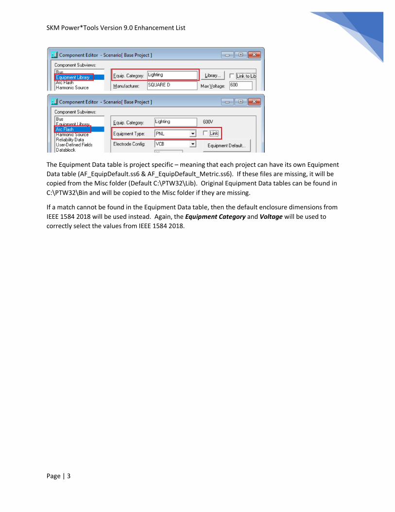
Component Editor now shows Box Dimensions
Equipment Type is taken directly from IEEE 1584 2018. Type consists of SWG, PNL, CBL, AIR, and MCC.
When linked, the software contains intelligence to correctly select the appropriate Type based on the
Equipment Category and Voltage. For example, if the software sees certain keywords in the Equipment
Category such as Panel in the word Panelboard, PNL will be selected for the Equipment Type. Refer to
IEEE 1584 2018 for a list of typical Equipment based on Voltage levels.
The Equipment Category is taken from the Bus library model. Additional entries may also be created by
directly typing into this field in the library model.
The Equipment Type and Equipment Category information may also be manually entered directly in the
Component Editor in lieu of selecting a Bus library model.
SKM Power*Tools Version 9.0 Enhancement List
Page | 3
The Equipment Data table is project specific – meaning that each project can have its own Equipment
Data table (AF_EquipDefault.ss6 & AF_EquipDefault_Metric.ss6). If these files are missing, it will be
copied from the Misc folder (Default C:\PTW32\Lib). Original Equipment Data tables can be found in
C:\PTW32\Bin and will be copied to the Misc folder if they are missing.
If a match cannot be found in the Equipment Data table, then the default enclosure dimensions from
IEEE 1584 2018 will be used instead. Again, the Equipment Category and Voltage will be used to
correctly select the values from IEEE 1584 2018.

SKM Power*Tools Version 9.0 Enhancement List
Page | 4
Using Data Visualizer to change enclosure dimensions for multiple equipment simultaneously
1. Unlink the Box Dimensions. This can easily be done within Arc Flash.
2. Open Data Visualizer and click on Components. Select the buses (or protective devices) that you
want to change the box dimensions for.

SKM Power*Tools Version 9.0 Enhancement List
Page | 5
3. Click on Datablock and create a new Format. Enter a format name of “Change Box Dimensions”.
Add the attributes shown below.
4. Click on Options. Under Group Data By, select Attribute.

SKM Power*Tools Version 9.0 Enhancement List
Page | 6
5. Now that all the dimensions are sorted together, select multiple rows, right-click and select
Global Change. You can now enter the new desired value.

SKM Power*Tools Version 9.0 Enhancement List
Page | 7
ANALYZE MULTIPLE ELECTRODE CONFIGURATIONS
Electrode configuration plays a crucial factor in the determination of the incident energy. What happens
when a VCBB configuration becomes VCB during an arc flash incident? The PTW software can now
automatically analyze other possible electrode configurations and report the higher incident energy
result. This is available for equipment configured as VCBB or HCB. Note that HCB is almost always result
in a higher incident energy compared to VCB or VCBB. The option is made available for peace of mind
and should not be needed on a regular basis.
When another electrode configuration is found to produce a higher incident energy, a (*N25a), (*N25b),
or (*N25c) indication will be displayed for that bus.
Alternative approach to analyzing different Electrode Configurations:
Scenarios can be created of the Base project where each scenario has all equipment set to a particular
electrode configuration. In the example below:
• Scenario S1 has VCB set as the electrode configuration for all equipment.
• Scenario S2 has VCBB set as the electrode configuration for all equipment.
• Scenario S3 has HCB set as the electrode configuration for all equipment.
In the Arc Flash Scenario options, select “Display Incident Energy From – Worst Case Scenario”. The Arc
Flash spreadsheet will compare all scenarios and report the highest incident energy from all selected
scenarios. Graphically, the results can also be viewed by applying new Datablock attributes introduced
in Version 9.0. AFWC_ElectrodeConfig will show the electrode configuration used to determine the

SKM Power*Tools Version 9.0 Enhancement List
Page | 8
highest incident energy. AFWC_IncidentEnergy will show the actual highest incident energy across all
scenarios.
SKM Power*Tools Version 9.0 Enhancement List
Page | 9
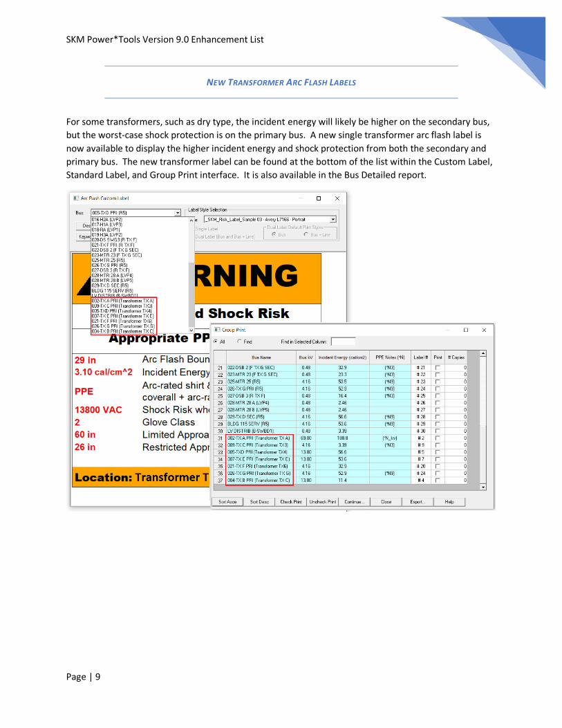
NEW TRANSFORMER ARC FLASH LABELS
For some transformers, such as dry type, the incident energy will likely be higher on the secondary bus,
but the worst-case shock protection is on the primary bus. A new single transformer arc flash label is
now available to display the higher incident energy and shock protection from both the secondary and
primary bus. The new transformer label can be found at the bottom of the list within the Custom Label,
Standard Label, and Group Print interface. It is also available in the Bus Detailed report.

SKM Power*Tools Version 9.0 Enhancement List
Page | 10
FREESTANDING EQUIPMENT
When protective devices are located in separate enclosures within switchgears or MCCs, it is now
possible to enter another set of data for electrode configuration, enclosure size, gap, and working
distance. This allows arc flash evaluation at this separate location within the same equipment and
printing of its own arc flash label.
Setting a protective device to be a Freestanding Equipment can also be done within Arc Flash Evaluation.

SKM Power*Tools Version 9.0 Enhancement List
Page | 11
The Bus, Line Side, and Load Side Calculations will have its own equipment parameters that are
independent of each other providing flexibility to simulate actual conditions. The Equipment Category is
always enabled in the Component Editor and within the Arc Flash spreadsheet. Box dimensions, Gap,
and Working Distance will automatically be populated based on the Equipment Default Table.

SKM Power*Tools Version 9.0 Enhancement List
Page | 12
ENHANCE ARC FLASH LABEL PRINTING OF OVERDUTIED EQUIPMENT
To help sort and print custom Deficient arc flash labels for Overdutied equipment, the text “OVERDUTY”
is now shown for equipment that have a Failed status in Equipment Evaluation. First select a Deficient
label and go to the Group Print interface. Sorting by OVERDUTY allows easy selection and printing of a
custom label.

SKM Power*Tools Version 9.0 Enhancement List
Page | 13
NEW DATABLOCK ATTRIBUTES
AF_BoxDepth- The depth of an enclosed equipment such as Panelboards, Switchgears, and MCCs. Used
as a parameter in Incident Energy and Flash Boundary calculations for types VCB, VCBB, and HCB.
AF_BoxHeight - The height of an enclosed equipment such as Panelboards, Switchgears, and MCCs. Used
as a parameter in Incident Energy and Flash Boundary calculations for types VCB, VCBB, and HCB.
AF_BoxWidth - The width of an enclosed equipment such as Panelboards, Switchgears, and MCCs. Used
as a parameter in Incident Energy and Flash Boundary calculations for types VCB, VCBB, and HCB.
AF_BoxSizeCF – Shows the enclosure correction factor used for calculating the incident energy and flash
boundary using the IEEE 1584-2018 method.
AF_ElectrodeConfig - Bus electrode configuration of the equipment with 5 choices: VCB - Vertical
Electrodes in Cubic Box, VCBB - Vertical Electrodes in Cubic Box with Barrier, HCB - Horizontal
Electrodes in Cubic Box, VOA - Vertical Electrodes in Open Air, and HOA - Horizontal Electrodes in Open
Air.
AF_UnLinkedBoxDimensions - indicate if the bus box dimensions are linked.
AFWC_ElectrodeConfig – The bus electrode configuration of the equipment used for the worst case
scenario incident energy.
AF_MinArcingFault - Shows the arcing current variation correction factor used for calculating the
incident energy and flash boundary using the IEEE 1584-2018 method.
AF_MaxFaultInScenarios – Shows the highest Short Circuit Fault current (Bolted Fault) among all the
scenarios regardless of the incident energy value.

SKM Power*Tools Version 9.0 Enhancement List
Page | 14
UPDATED CRYSTAL REPORTS

SKM Power*Tools Version 9.0 Enhancement List
Page | 15
NEW RELAY SEGMENT
IEC 60255-8 Thermal Overload Protection (49) - New relay modeling segment for creating libraries that
are based on the IEC 60255-8 thermal overload protection. Added for Siemens 7SK80, GE 869, and SEL
700G in the library.

SKM Power*Tools Version 9.0 Enhancement List
Page | 16
OTHER MISCELLANEOUS ENHANCEMENTS
Speed improvements in conducting Arc Flash studies
Improved Arc Flash miscoordination reporting when an ATS is involved.
Improved input data formatting for the new Arc Flash IEEE 1584 2018 standard.
Improved Arc Flash worst case result Datablock reporting.
Enhanced Arc Flash Evaluation to better handle 3-winding transformers where loops are involved.
Improved Arc Flash Incident Energy Lines in TCC drawings.
Improved the Arc Flash Line and Load Side minimal arcing fault calculations using IEEE 1584 2018.
Added ANSI LLG to Equipment Evaluation.
Updated the protective device library. Refer to "Readme V9.0 Lib Changes.pdf" for more information.


![[ 3000 Series Time Delay Relays and Measuring Relays ... · [ 3000 Series Time Delay Relays and Measuring Relays ] ... Measuring Relays ] • Time Delay Relays ... Dear Reader, Dear](https://static.fdocuments.in/doc/165x107/5b85683b7f8b9aec488e43dd/-3000-series-time-delay-relays-and-measuring-relays-3000-series-time.jpg)