CEA Standardread.pudn.com/downloads178/ebook/828201/EIA-CEA-861E.pdf · NOTICE Consumer Electronics...
160
CEA Standard A DTV Profile for Uncompressed High Speed Digital Interfaces CEA-861-E March 2008 Copyright Consumer Electronics Association Provided by IHS under license with CEA Sold to:GARY LI, W0519542 Not for Resale,2008/5/29 21:49:15 GMT No reproduction or networking permitted without license from IHS --``````,``,`,```,``,-`-`,,`,,`,`,,`---
Transcript of CEA Standardread.pudn.com/downloads178/ebook/828201/EIA-CEA-861E.pdf · NOTICE Consumer Electronics...

CEA Standard
A DTV Profile for Uncompressed High Speed Digital Interfaces
CEA-861-E
March 2008
Copyright Consumer Electronics Association Provided by IHS under license with CEA Sold to:GARY LI, W0519542
Not for Resale,2008/5/29 21:49:15 GMTNo reproduction or networking permitted without license from IHS
--``````,``,`,```,``,-`-`,,`,,`,`,,`---

NOTICE
Consumer Electronics Association (CEA®) Standards, Bulletins and other technical publications are designed to serve the public interest through eliminating misunderstandings between manufacturers and purchasers, facilitating interchangeability and improvement of products, and assisting the purchaser in selecting and obtaining with minimum delay the proper product for his particular need. Existence of such Standards, Bulletins and other technical publications shall not in any respect preclude any member or nonmember of CEA from manufacturing or selling products not conforming to such Standards, Bulletins or other technical publications, nor shall the existence of such Standards, Bulletins and other technical publications preclude their voluntary use by those other than CEA members, whether the standard is to be used either domestically or internationally. Standards, Bulletins and other technical publications are adopted by CEA in accordance with the American National Standards Institute (ANSI) patent policy. By such action, CEA does not assume any liability to any patent owner, nor does it assume any obligation whatever to parties adopting the Standard, Bulletin or other technical publication. This CEA Standard is considered to have International Standardization implication, but the International Electrotechnical Commission activity has not progressed to the point where a valid comparison between the CEA Standard and the IEC document can be made. This Standard does not purport to address all safety problems associated with its use or all applicable regulatory requirements. It is the responsibility of the user of this Standard to establish appropriate safety and health practices and to determine the applicability of regulatory limitations before its use. (Formulated under the cognizance of the CEA’s R4.8 DTV Interface Subcommittee.) Published by ©CONSUMER ELECTRONICS ASSOCIATION 2008 Technology & Standards Department 1919 S. Eads Street Arlington, Virginia 22202 PRICE: Please call Information Handling Services, USA and Canada (1-800-854-7179) International (303-397-7956), or
http://global.ihs.com All rights reserved Printed in U.S.A.
Copyright Consumer Electronics Association Provided by IHS under license with CEA Sold to:GARY LI, W0519542
Not for Resale,2008/5/29 21:49:15 GMTNo reproduction or networking permitted without license from IHS
--``````,``,`,```,``,-`-`,,`,,`,`,,`---

PLEASE!
DON'T VIOLATE THE
LAW!
This document is copyrighted by the Consumer Electronics Association (CEA®) and may not be reproduced without permission.
Organizations may obtain permission to reproduce a limited number of copies by
entering into a license agreement. For information contact:
Information Handling Services 15 Inverness Way East
Englewood, Colorado 80112-5704 or call U.S.A. and Canada 1-800-854-7179, International (303) 397-7956
See http://global.ihs.com or email [email protected]
Copyright Consumer Electronics Association Provided by IHS under license with CEA Sold to:GARY LI, W0519542
Not for Resale,2008/5/29 21:49:15 GMTNo reproduction or networking permitted without license from IHS
--``````,``,`,```,``,-`-`,,`,,`,`,,`---

Copyright Consumer Electronics Association Provided by IHS under license with CEA Sold to:GARY LI, W0519542
Not for Resale,2008/5/29 21:49:15 GMTNo reproduction or networking permitted without license from IHS
--``````,``,`,```,``,-`-`,,`,,`,`,,`---

CEA-861-E
i
Contents
1 Scope ......................................................................................................................................................... 1
2 General ...................................................................................................................................................... 1 2.1 References ........................................................................................................................................ 1
2.1.1 Normative References ................................................................................................................ 1 2.1.1.1 Normative Reference List .................................................................................................. 1 2.1.1.2 Normative Reference Acquisition .................................................................................... 3
2.1.2 Informative References .............................................................................................................. 3 2.1.2.1 Informative Document List ................................................................................................ 4 2.1.2.2 Informative Document Acquisition .................................................................................. 5
2.2 Definitions ......................................................................................................................................... 6 2.3 Symbols and Abbreviations .......................................................................................................... 10 2.4 Compliance Notation ...................................................................................................................... 11 2.5 Hexidecimal Notation ..................................................................................................................... 11 2.6 HxV Video Timing Notation ........................................................................................................... 11 2.7 Bit Naming Conventions ................................................................................................................ 12 2.8 ASCII Codes, Characters & Strings .............................................................................................. 12
3 Overview ................................................................................................................................................. 12 3.1 General Video Format Requirements ........................................................................................... 13
4 Video Formats and Waveform Timings ............................................................................................... 14 4.1 Aspect Ratio .................................................................................................................................... 26 4.2 Frame Rate Relationships ............................................................................................................. 29
5 Color Encoding, Sampling, & Conversion ........................................................................................... 29 5.1 Default Encoding Parameters ....................................................................................................... 29 5.2 Color Component Samples ........................................................................................................... 30
5.2.1 RGB-to-YCBCR Conversion Matrices ....................................................................................... 30 5.2.2 Sample Lattice ........................................................................................................................... 30
5.3 Transfer Characteristic (e.g. gamma correction) ........................................................................ 31 5.4 Color Coding & Quantization ........................................................................................................ 32
6 ––Auxiliary Information Carried from Source to Sink ........................................................................ 32 6.1 Vendor Specific InfoFrames .......................................................................................................... 33 6.2 Auxiliary Video Information (AVI) InfoFrame ............................................................................... 34 6.3 Format of Version 1 AVI InfoFrame .............................................................................................. 35 6.4 Format of Version 2 AVI InfoFrame .............................................................................................. 35 6.5 Source Product Description (SPD) InfoFrame ............................................................................. 46 6.6 Audio InfoFrame ............................................................................................................................. 47
6.6.1 Audio Identification Information ............................................................................................. 48 6.6.2 Speaker Mapping and Down-mix Information ....................................................................... 50
6.7 MPEG Source InfoFrame ............................................................................................................... 54 6.8 NTSC VBI InfoFrame ....................................................................................................................... 55
7 EDID Data Structure ............................................................................................................................... 55 7.1 Use of CEA Extensions .................................................................................................................. 56 7.2 Describing Video Formats in EDID ............................................................................................... 57
7.2.1 Use of EDID Detailed Timing Descriptors .............................................................................. 57 7.2.2 Order of Dual-Aspect Ratio Detailed Timing Descriptors .................................................... 58 7.2.3 Source Requirements and Recommendations ...................................................................... 59
7.3 CEA Extension Version 1 ............................................................................................................... 59
Copyright Consumer Electronics Association Provided by IHS under license with CEA Sold to:GARY LI, W0519542
Not for Resale,2008/5/29 21:49:15 GMTNo reproduction or networking permitted without license from IHS
--``````,``,`,```,``,-`-`,,`,,`,`,,`---

CEA-861-E
ii
7.4 CEA Extension Version 2 ............................................................................................................... 60 7.5 CEA Extension Version 3 ............................................................................................................... 61
7.5.1 Video Data Block ....................................................................................................................... 65 7.5.2 Audio Data Block ...................................................................................................................... 65 7.5.3 Speaker Allocation Data Block ................................................................................................ 66 7.5.4 Vendor Specific Data Block ..................................................................................................... 67 7.5.5 Colorimetry Data Block ............................................................................................................ 67 7.5.6 Video Capability Data Block .................................................................................................... 68 7.5.7 Vendor-Specific Video Data Block..................................................................................... 70 7.5.8 Vendor-Specific Audio Data Block .................................................................................... 70
Annex A Baseline Example EDID and Detailed Timing Descriptors (Informative) ............................. 72 A.1 Background .................................................................................................................................... 72 A.2 EDID Tables .................................................................................................................................... 72
A.2.1 EDID Table Construction ......................................................................................................... 72 A.2.2 Detailed Explanation of EDID Block Zero .............................................................................. 73 A.2.3 Block Zero Header Section ..................................................................................................... 73 A.2.4 Vendor / Product Identification ............................................................................................... 73 A.2.5 EDID Version ............................................................................................................................. 75 A.2.6 Basic Display Parameters and Features ................................................................................ 75 A.2.7 Color Characteristics ............................................................................................................... 78 A.2.8 Established Timings ................................................................................................................ 79 A.2.9 Standard Timing ID #1 – 8 ....................................................................................................... 80 A.2.10 Detailed Timing Descriptor Block ......................................................................................... 80
A.2.10.1 First Detailed Timing Descriptor .................................................................................. 80 A.2.10.2 Second Detailed Timing Descriptor ............................................................................ 81 A.2.10.3 First Monitor Descriptor (Monitor Name) .................................................................... 82 A.2.10.4 Second Monitor Descriptor (Monitor Range Limits) .................................................. 83
A.2.11 Extension Flag and Checksum ............................................................................................. 84 A.2.11.1 Block One Details .......................................................................................................... 85
A.2.12 Overview of Extensions ......................................................................................................... 85 A.2.13 Block One CEA Extension Header ....................................................................................... 86 A.2.14 Third Detailed Timing Descriptor ......................................................................................... 87 A.2.15 Fourth Detailed Timing Descriptor ....................................................................................... 87 A.2.16 Descriptor Defined by Manufacturer .................................................................................... 88 A.2.17 Monitor Serial Number ........................................................................................................... 89 A.2.18 Residual Byte Padding and Check Sum .............................................................................. 89 A.2.19 Hot Plugging Sequence ......................................................................................................... 91
A.3 Complete Example EDID Table (Informative) .............................................................................. 92 A.4 Example EDID Detailed Timing Descriptors ................................................................................ 99
Annex B Application to DVI 1.0 (Normative) ........................................................................................ 111 B.1 Connector and Cable ................................................................................................................... 111 B.2 Digital Content Protection ........................................................................................................... 111
Annex C Application to Open LDI (Normative) .................................................................................... 112 C.1 Open LDI Data and Control Signals ........................................................................................... 112 C.2 Non DC Balanced Mode .............................................................................................................. 112 C.3 OpenLDI Cabling Information ..................................................................................................... 112
C.3.1 Cable Length ........................................................................................................................... 113 C.3.2 Number of Signal Conductors .............................................................................................. 113 C.3.3 Wire Gauge ............................................................................................................................. 113 C.3.4 Conductor Resistance ........................................................................................................... 113 C.3.5 Insulation ................................................................................................................................ 113 C.3.6 Shield Requirement ............................................................................................................... 113 C.3.7 Single Twisted Pair Transmission Skew ............................................................................. 113
Copyright Consumer Electronics Association Provided by IHS under license with CEA Sold to:GARY LI, W0519542
Not for Resale,2008/5/29 21:49:15 GMTNo reproduction or networking permitted without license from IHS
--``````,``,`,```,``,-`-`,,`,,`,`,,`---
CEA-861-E
iii
C.3.8 Multiple Twisted Pair Transmission Skew ........................................................................... 113 C.3.9 USB Cable Requirements ...................................................................................................... 113 C.3.10 DDC Cable Requirements .................................................................................................... 113
Annex D Application to HDMI (Informative) ......................................................................................... 114 D.1 InfoPackets ................................................................................................................................... 114 D.2 EDID ............................................................................................................................................... 114 D.3 Audio ............................................................................................................................................. 114 D.4 HDCP ............................................................................................................................................. 114 D.5 Additional Information ................................................................................................................. 114 D.6 Example EDID Using Elements of CEA Block Tag Extension (Applicable to HDMI) ............ 114
D.6.1 First Monitor Descriptor (Monitor Name) and Second Monitor Descriptor (Monitor Range Limits) ............................................................................................................................................... 114 D.6.2 Extension Flag and Checksum ............................................................................................. 115 D.6.3 CEA Extension Header (Block 1) .......................................................................................... 115 D.6.4 CEA Data Block Collection .................................................................................................... 115 D.6.5 Video Data Block .................................................................................................................... 115 D.6.6 CEA Audio Block .................................................................................................................... 116 D.6.7 Speaker Allocation Block ...................................................................................................... 116 D.6.8 Vendor Specific Block ........................................................................................................... 117 D.6.9 Complete CEA-861-E Example with Block Tag Extension ................................................. 118
Annex E [Reserved for Future Use] ...................................................................................................... 127
Annex F Guidance for Source & Sinks (Informative) .......................................................................... 128 F.1 Overview ........................................................................................................................................ 128 F.2 Background ................................................................................................................................... 128 F.3 Guidance for Sources .................................................................................................................. 128
F.3.1 Stable Video Format ............................................................................................................... 129 F.3.2 Changing Video Format ......................................................................................................... 129 F.3.3 Optional User Controlled Setting .......................................................................................... 131 F.3.4 Non-Default Scenarios ........................................................................................................... 131 F.3.5 Errors Reading the EDID ........................................................................................................ 132
F.4 Guidance for Sinks ....................................................................................................................... 132 F.4.1 Valid Read-Only EDID ............................................................................................................ 133 F.4.2 Ordering of the Video Formats in the EDID ......................................................................... 133 F.4.3 Video Information Code (VIC) Transition ............................................................................. 133
Annex G InfoPacket Framework (Informative) ..................................................................................... 134
Annex H Active Format Description (Informative) ............................................................................... 135 H.1 ATSC Active Format Description ............................................................................................... 135 H.2 DVB Active Format Description .................................................................................................. 137
Annex I Picture Aspect Ratio Conversion Example (Informative) ..................................................... 140
Annex J [ Intentionally Omitted ] ........................................................................................................... 141
Annex K Audio Speaker Placement & Channel Allocation Compatibility (Informative) .................. 142
Annex L Video Timing Examples (Informative) .................................................................................... 144
Copyright Consumer Electronics Association Provided by IHS under license with CEA Sold to:GARY LI, W0519542
Not for Resale,2008/5/29 21:49:15 GMTNo reproduction or networking permitted without license from IHS
--``````,``,`,```,``,-`-`,,`,,`,`,,`---

CEA-861-E
iv
Figures Figure 1. General Progressive Video Format Timing (Negative Sync) ................................................ 21 Figure 2. General Progressive Video Format Timing (Positive Sync) ................................................. 22 Figure 3 General Interlaced Video Format Timing (Negative Sync) .................................................... 23 Figure 4. General Interlaced Video Format Timing (Positive Sync) ..................................................... 24 Figure 5 Special Interlaced Video Format Timing (Even Vtotal) .......................................................... 25 Figure 6 Speaker Placement .................................................................................................................... 51 Figure 7 OpenLDI Synchronization ....................................................................................................... 112 Figure 8 Video Processing Chain .......................................................................................................... 128 Figure 9 Example of Options for Format Conversion ......................................................................... 130 Figure 10 Multiple Conversions Example ............................................................................................. 131 Figure 11. Active Format Illustration (ATSC) ....................................................................................... 135 Figure 12 Active Format Illustration (DVB) ........................................................................................... 138 Figure 13 Example of Problem Resulting from Double Stretch ......................................................... 140 Figure 14 General Progressive Example for Video ID Codes 2 & 3 (720x480p @ 60 Hz) ................ 144 Figure 15 General Interlace Example for Video ID Code 5 (1920x1080i @ 60 Hz) ............................ 145 Figure 16 Special Interlace Example for Video ID Code 39 (1920x1080i-1250 Vtotal @ 50 Hz) ...... 146
Tables Table 1 Video Format Timings—Support Requirements and Recommendations ............................. 14 Table 2 Video Format Timings—Detailed Timing Information ............................................................. 16 Table 3 Video Format Timings—Detailed Sync Information ................................................................. 18 Table 4 Video Formats—Video ID Code and Aspect Ratios ................................................................. 27 Table 5 Frame Rate Relationships—Base to High Frame Rate VICs ................................................... 29 Table 6 List of InfoFrame Type Codes .................................................................................................... 33 Table 7 Vendor Specific InfoFrame ......................................................................................................... 34 Table 8 Auxiliary Video Information InfoFrame format (Version 1) ..................................................... 35 Table 9 Auxiliary Video Information (AVI) InfoFrame Format (Version 2) ........................................... 36 Table 10 AVI InfoFrame Data Byte 1 ........................................................................................................ 37 Table 11 AVI InfoFrame Data Byte 2 ........................................................................................................ 38 Table 12 Common Active Formats .......................................................................................................... 39 Table 13 AVI InfoFrame Data Byte 3 ........................................................................................................ 39 Table 14 Picture Colorimetry Indicated by the RGB or YCBCR (Y), Colorimetry (C) and Extended
Colorimetry (EC) Field Settings ...................................................................................................... 41 Table 15 AVI InfoFrame Pixel Repetition Field, Data Byte 5 ................................................................. 41 Table 16 AVI Info Frame IT Contents Type, Data Byte 5 ....................................................................... 42 Table 17 AVI Info Frame YCC Quantization Range, Data Byte 5 .......................................................... 43 Table 18 Valid Pixel Repeat Values for Each Video Format Timing .................................................... 44 Table 19 Typical Gaming Format AVI InfoFrame Parameters ............................................................. 45 Table 20 Video Format Information (Informative) ................................................................................. 45 Table 21 Source Product Description InfoFrame Format ..................................................................... 46 Table 22 Source Product Description InfoFrame Data Byte 25 ............................................................ 47 Table 23 Audio InfoFrame Format ........................................................................................................... 48 Table 24 Audio InfoFrame Data Byte 1 ................................................................................................... 49 Table 25 Audio InfoFrame Data Byte 2 ................................................................................................... 50 Table 26 Audio Format Code Extension (Data Byte 3) .......................................................................... 50 Table 27 Speaker Placement .................................................................................................................... 51 Table 28 Audio InfoFrame Data Byte 4 ................................................................................................... 53 Table 29 Audio InfoFrame Data Byte 5, Level Shift Value .................................................................... 53
Copyright Consumer Electronics Association Provided by IHS under license with CEA Sold to:GARY LI, W0519542
Not for Resale,2008/5/29 21:49:15 GMTNo reproduction or networking permitted without license from IHS
--``````,``,`,```,``,-`-`,,`,,`,`,,`---
CEA-861-E
v
Table 30 Audio InfoFrame Data Byte 5, Down-mix Inhibit Flag ............................................................ 53 Table 31 Audio InfoFrame Data Byte 5, LFE Playback Level Information .......................................... 54 Table 32 MPEG Source InfoFrame format .............................................................................................. 54 Table 33 MPEG Source InfoFrame Data Byte 5 ...................................................................................... 55 Table 34 NTSC VBI InfoFrame.................................................................................................................. 55 Table 35 Video Timing Code 39 Detailed Timing Descriptor ................................................................ 58 Table 36 CEA Extension Version 1 .......................................................................................................... 60 Table 37 CEA Extension Version 2 .......................................................................................................... 61 Table 38 CEA Extension Version 3 .......................................................................................................... 62 Table 39 General Format of “CEA Data Block Collection” ................................................................... 63 Table 40 Data Block Header Byte ............................................................................................................ 64 Table 41 CEA Data Block Tag Codes ...................................................................................................... 64 Table 42 Extended Tag Format (2nd Byte of Data Block) ....................................................................... 64 Table 43 CEA Data Block Tag Codes ...................................................................................................... 64 Table 44 Short Video Descriptor ............................................................................................................. 65 Table 45 CEA Short Audio Descriptor for Audio Format Code = 1 (LPCM) ........................................ 66 Table 46 CEA Short Audio Descriptor for Audio Format Codes 2 to 8 ............................................... 66 Table 47 CEA Short Audio Descriptor for Audio Format Codes 9 to 13 ............................................. 66 Table 48 CEA Short Audio Descriptor for Audio Format Code 14 (WMA Pro) ................................... 66 Table 49 CEA Short Audio Descriptor for Audio Format Code 15 (extension) ................................... 66 Table 50 Speaker Allocation Data Block Payload .................................................................................. 67 Table 51 Colorimetry Data Block ............................................................................................................. 67 Table 52 Data Byte 3 Colorimetry Support Flags .................................................................................. 67 Table 53 Data Byte 4 Colorimetry Metadata Support Flags .................................................................. 68 Table 54 Video Capability Data Block (VCDB) ....................................................................................... 68 Table 55 Video Capability Descriptor Data Byte 3 ................................................................................. 68 Table 56 Vendor-Specific Video Data Block (VSVDB) ........................................................................... 70 Table 57 Vendor-Specific Audio Data Block (VSADB) .......................................................................... 71 Table 58 Standard Data Lengths ............................................................................................................. 73 Table 59 Block Zero Header ..................................................................................................................... 73 Table 60 Vendor / Product Identification; Showing Manufacturer Week and year ............................. 75 Table 61 Vendor / Product Identification ................................................................................................ 75 Table 62 Example 0x15, 0x16 EDID Screen Size Data and Certain Display Categories .................... 76 Table 63 Feature Support Detail .............................................................................................................. 77 Table 64 Basic Display Parameters and Features Block ...................................................................... 78 Table 65 Binary to Decimal Conversion Example ................................................................................. 78 Table 66 Color Characteristics Block ..................................................................................................... 79 Table 67 Established Timings Block ....................................................................................................... 79 Table 68 Standard Timing ID Block ......................................................................................................... 80 Table 69 First Detailed Timing Descriptor Block (1920x1080i Example) ............................................. 81 Table 70 Second Detailed Timing Descriptor Block (720x480p, 4:3 Example) ................................... 82 Table 71 First Monitor Descriptor Block (Monitor Name) ..................................................................... 83 Table 72 Second Monitor Descriptor Block (Monitor Range Limits) ................................................... 84 Table 73 Extension Flag Block ................................................................................................................ 85 Table 74 Block One CEA Extension Header ........................................................................................... 86 Table 75 Third Detailed Timing Descriptor Block (720p, 16:9 Example) ............................................. 87 Table 76 Fourth Detailed Timing Descriptor Block (480i, 4:3 Example) .............................................. 88 Table 77 Descriptor Defined by Manufacturer Block ............................................................................ 89 Table 78 Monitor Serial Number Block ................................................................................................... 89 Table 79 Residual Byte Stuffing and Check Sum Block ....................................................................... 90 Table 80 Complete EDID Example ........................................................................................................... 92 Table 81 Example EDID Detailed Timing Descriptor for 1280x720p (60 Hz, 16:9) .............................. 99 Table 82 Example EDID Detailed Timing Descriptor for 1920x1080i (60 Hz, 16:9) ........................... 100 Table 83 Example EDID Detailed Timing Descriptor for 720x480p (59.94 Hz, 4:3) ........................... 101 Table 84 Example EDID Detailed Timing Descriptor for 720x480p (59.94Hz, 16:9) .......................... 102 Table 85 Example EDID Detailed Timing Descriptor for 720x480i (59.94Hz, 4:3) ............................. 103
Copyright Consumer Electronics Association Provided by IHS under license with CEA Sold to:GARY LI, W0519542
Not for Resale,2008/5/29 21:49:15 GMTNo reproduction or networking permitted without license from IHS
--``````,``,`,```,``,-`-`,,`,,`,`,,`---

CEA-861-E
vi
Table 86 Example EDID Detailed Timing Descriptor for 720x480i (59.94Hz, 16:9) ........................... 104 Table 87 Example EDID Detailed Timing Descriptor for 1280x720p (50 Hz, 16:9) ............................ 105 Table 88 Example EDID Detailed Timing Descriptor for 1920x1080i (50 Hz, 16:9) ........................... 106 Table 89 Example EDID Detailed Timing Descriptor for 720x576p (50 Hz, 4:3) ................................ 107 Table 90 Example EDID Detailed Timing Descriptor for 720x576p (50 Hz, 16:9) .............................. 108 Table 91 Example EDID Detailed Timing Descriptor for 720x576i (50 Hz, 4:3) ................................. 109 Table 92 Example EDID Detailed Timing Descriptor for 720x576i (50 Hz, 16:9) ............................... 110 Table 93 OpenLDI Control Signals ........................................................................................................ 112 Table 94 CEA Extension Header (Block 1) ........................................................................................... 115 Table 95 Video Data Block ..................................................................................................................... 116 Table 96 Audio Data Block ..................................................................................................................... 116 Table 97 Speaker Data Block ................................................................................................................. 117 Table 98 Vendor Specific Data Block .................................................................................................... 117 Table 99 CEA-861-E EDID Example with Block Tag Extension .......................................................... 118 Table 100 Illustrated ATSC AFD Coding ............................................................................................... 137 Table 101 Illustrated DVB AFD Coding ................................................................................................. 139 Table 102 SMPTE/CEA Audio Channel Description & Abbreviation Comparison ........................... 142 Table 103 SMPTE/CEA Audio Channel Assignment Comparison ..................................................... 143
Copyright Consumer Electronics Association Provided by IHS under license with CEA Sold to:GARY LI, W0519542
Not for Resale,2008/5/29 21:49:15 GMTNo reproduction or networking permitted without license from IHS
--``````,``,`,```,``,-`-`,,`,,`,`,,`---

CEA-861-E
vii
FOREWORD
This standard was developed under the auspices of the Consumer Electronics Association (CEA) R4.8 DTV Interface Subcommittee. CEA-861-E supersedes CEA-861-D.
Copyright Consumer Electronics Association Provided by IHS under license with CEA Sold to:GARY LI, W0519542
Not for Resale,2008/5/29 21:49:15 GMTNo reproduction or networking permitted without license from IHS
--``````,``,`,```,``,-`-`,,`,,`,`,,`---
CEA-861-E
viii
(This page intentionally left blank.)
Copyright Consumer Electronics Association Provided by IHS under license with CEA Sold to:GARY LI, W0519542
Not for Resale,2008/5/29 21:49:15 GMTNo reproduction or networking permitted without license from IHS
--``````,``,`,```,``,-`-`,,`,,`,`,,`---

CEA-861-E
1
A DTV Profile for Uncompressed High Speed Digital Interfaces
1 Scope CEA-861-E establishes protocols, requirements, and recommendations for the utilization of uncompressed digital interfaces by consumer electronics devices such as digital televisions (DTVs), digital cable, satellite or terrestrial set-top boxes (STBs), and related peripheral devices including, but not limited to DVD players/recorders, and other related sources or sinks. CEA-861-E is applicable to a variety of standard DTV-related high-speed digital physical interfaces - such as Digital Visual Interface (DVI) 1.0 [4], Open LVDS Display Interface (LDI) [8], and High-Definition Multimedia Interface (HDMI) [50] specifications. Protocols, requirements, and recommendations that are defined include video formats and waveforms; colorimetry and quantization; transport of compressed and uncompressed, as well as Linear Pulse Code Modulation (LPCM), audio; carriage of auxiliary data; and implementations of the Video Electronics Standards Association (VESA) Enhanced Extended Display Identification Data Standard (E-EDID) [10], which is used by sinks to declare display capabilities and characteristics. CEA-861-E adopters are strongly encouraged to implement High-bandwidth Digital Content Protection (HDCP) [3] content protection, defined by the Digital Content Protection, LLC (DCP) method, in order to be compatible with digital cable STBs as authorized by 47 C.F.R. § 76.602 [48] and 47 C.F.R. §76.640 [49]. HDCP [3] permits viewing of high-value content that may be available from other video sources in a home network.
2 General
2.1 References CEA-861-E includes mechanisms that allow a digital video source (such as a cable, satellite or terrestrial STB, digital VCR, or DVD player) to supply displayable, baseband, digital video to High Definition Television (HDTV) and Enhanced Definition Television (EDTV) devices, as well as peripheral devices such as repeaters, switchers, and recorders, as defined in CEA Expands Definitions for Digital Television Products [43].
2.1.1 Normative References The following standards contain provisions that, through reference in this text, constitute normative provisions of this standard. At the time of publication, the editions indicated were valid. All standards are subject to revision, and parties to agreements based on this standard are encouraged to investigate the possibility of applying the most recent editions of the standards listed in Sec. 2.1.1.1. If the referenced standard is dated, the reader is advised to use the version specified.
2.1.1.1 Normative Reference List 1. SMPTE 170M (2004), Composite Analog Video Signal—NTSC for Studio Applications 2. SMPTE 274M (2005), SMPTE Standard for Television—1920x1080 Image Sample Structure, Digital
Representation and Digital Timing Reference Sequences for Multiple-Picture Rates 3. DCP, L.L.C., HDCP Specification, Revision 1.1, June 9, 2003 4. DDWG, Digital Visual Interface, Revision 1.0, April 2, 1999 5. IEC 61966-2-4: Multimedia systems and equipment - Colour measurement and management - Part 2-
4: Colour management - Extended-gamut YCC colour space for video applications, January 2006 6. ITU-R BT.601-5, Studio Encoding parameters of digital television for standard 4:3 and wide-screen
16:9 aspect ratios, 1995 7. ITU-R BT.709-5, Parameter Values for the HDTV standards for production and International
Programme Exchange, 2002 8. Open LVDS Display Interface (Open LDI) Specification, Version 0.95, May 13, 1999 9. VESA E-DDC™ Standard, VESA Enhanced Display Data Channel Standard, Version 1.1, March 24,
2004 10. VESA E-EDID™ Standard, VESA Enhanced Extended Display Identification Data Standard, Release
A, Revision 1, February 9, 2000 --- Defines EDID Structure Version 1, Revision 3
Copyright Consumer Electronics Association Provided by IHS under license with CEA Sold to:GARY LI, W0519542
Not for Resale,2008/5/29 21:49:15 GMTNo reproduction or networking permitted without license from IHS
--``````,``,`,```,``,-`-`,,`,,`,`,,`---

CEA-861-E
2
11. VESA DDC/CI Standard, VESA Display Data Channel Command Interface (DDC/CI) Standard, Version 1.1, October 29, 2004
12. ATSC Standard A/52B, Digital Audio Compression Standard (AC-3, E-AC-3) Revision B, June 14, 2005
13. IEC 60958-3 Digital Audio Interface - Part 3: Consumer Applications, First Edition, 1999 14. IEC 61909, Audio recording - Minidisc system 15. IEC 61937-3:2007 Digital audio - Interface for non-linear PCM encoded audio bitstreams applying
IEC 60958 - Part 3: Non-linear PCM bitstreams according to the AC-3 and enhanced AC-3 formats 16. IEC 61937-4:2003 Digital audio - Interface for non-linear PCM encoded audio bitstreams applying
IEC 60958 - Part 4: Non-linear PCM bitstreams according to the MPEG audio formats 17. IEC 61937-5:2006, Digital audio - Interface for non-linear PCM encoded audio bitstreams applying
IEC 60958 - Part 5: Non-linear PCM bitstreams according to the DTS (Digital Theater Systems) format(s)
18. IEC 61937-6:2006 Digital audio - Interface for non-linear PCM encoded audio bitstreams applying IEC 60958 - Part 6: Non-linear PCM bitstreams according to the MPEG-2 AAC and MPEG-4 AAC audio formats
19. IEC 61937-7:2004, Digital audio - Interface for non-linear PCM encoded audio bitstreams applying IEC 60958 - Part 7: Non-linear PCM bitstreams according to the ATRAC, ATRAC2/3 and ATRAC-X formats
20. IEC 61937-8:2006, Digital audio - Interface for non-linear PCM encoded audio bitstreams applying IEC 60958 - Part 8: Non-linear PCM bitstreams according to the Windows Media Audio (WMA) Professional format
21. IEC 61937-9:2007 Digital audio - Interface for non-linear PCM encoded audio bitstreams applying IEC 60958 - Part 9: Non-linear PCM bitstreams according to the MAT format
22. ISO/IEC 11172-3:1993, Information Technology - Coding of moving pictures and associated audio for digital storage media at up to about 1.5 Mbit/sec, Part 3: Audio, 1993
23. ISO/IEC 13818-3, Information Technology - Generic coding of moving pictures and associated audio information, Part 3: Audio, Second Edition, 1998-04-15
24. ISO/IEC 14496-3:2005, Information Technology – Coding of audio-visual objects – Part 3: Audio 25. ISO/IEC 14496-3:2005/AMD2:2006, Information Technology - Coding of audio-visual objects - Part 3:
Audio, Amendment 2: Audio Lossless Coding (ALS), new audio profiles and BSAC extensions 26. ISO/IEC 23003-1:2007 Information technology -- MPEG audio technologies -- Part 1: MPEG
Surround 27. DVD Forum, DVD Specifications for Read-Only Disc, Part 4, Audio Specifications, Version 1.0,
Meridian Lossless Packing 28. DVD Forum, DVD Specifications for High Definition Video, Version 1.0, DTS-HD Reference
Information 29. SCTE 127:2007, Carriage of Vertical Blanking Interval (VBI) Data in North American Digital Television
Bitstreams 30. Microsoft, WMA Pro Decoder Specification: An Overview of Windows Media Audio Professional
decoder 31. CEA-770.2-D, Standard Definition TV Analog Component Video Interface, April 2007 32. CEA-770.3-C, High Definition TV Analog Component Video Interface, August 2001 33. IEC 61966-2-5, Multimedia systems and equipment - Colour measurement and management - Part 2-
5: Colour management - Optional RGB colour space – opRGB 34. IEC 61966-2-1:1999, Multimedia systems and equipment - Colour measurement and management -
Part 2-1: Colour management - Default RGB colour space – sRGB 35. IEC 61966-2-1/Amendment 1:2003 Multimedia systems and equipment - Colour measurement and
management - Part 2-1: Colour management - Default RGB colour space – sRGB 36. SMPTE 2016-1 (2007) Television - Format for Active Format Description and Bar Data 37. ETSI 102 114 v1.1.1, DTS Coherence Acoustics; Core and Extensions, 2002-08 38. ANSI INCITS 4-1986 (R2002) Coded Character Sets - 7-Bit American National Standard Code for
Information Interchange (7-Bit ASCII), Table 8
Copyright Consumer Electronics Association Provided by IHS under license with CEA Sold to:GARY LI, W0519542
Not for Resale,2008/5/29 21:49:15 GMTNo reproduction or networking permitted without license from IHS
--``````,``,`,```,``,-`-`,,`,,`,`,,`---

CEA-861-E
3
2.1.1.2 Normative Reference Acquisition ANSI/CEA Standards • Global Engineering Documents, World Headquarters, 15 Inverness Way East, Englewood, CO USA
80112-5776; Phone 800-854-7179; Fax 303-397-2740; Internet global.ihs.com; Email [email protected]
ANSI/SMPTE Standards • Society of Motion Picture and Television Engineers, 595 W. Hartsdale Avenue, White Plains, NY
10607-1824; Phone 914-761-1100; Fax 914-761-3115; Internet http://www.smpte.org DDWG • Contact Digital Display Working Group (DDWG); Attn: DDWG Administrator; M/S JF3-361; 2111 NE
25th Avenue, Hillsboro, OR 97124-5961, USA; Fax: 503-264-5959; Internet http://www.ddwg.org; Email [email protected]
DTS • DTS, Inc., 5171 Clareton Drive, Agoura Hills, CA 91301, USA; Phone 818-706-3525; Fax 818-706-
1868; Internet http://www.dts.com/contact/dts-headquarters.php DVD Forum • Office of Secretary, DVD FORUM, Daimon Urbanist Bldg. 6F, 2-3-6 Shibadaimon, Minato-ku, Tokyo
105-0012, Japan ; Phone +81 35 777 2881; Fax +81 35 777 2882; Internet http://www.dvdforum.org HDCP • Digital Content Protection, L.L.C., c/o Intel Corporation, Stephen Balogh, JF2-55; 2111 NE 25th Ave;
Hillsboro, OR 97124; Email [email protected]; Internet http://www.digital-cp.com/home or www.digital-cp.com
ITU Standards • International Telecommunications Union, Place des Nations, CH-1211 Geneva 20, Switzerland;
Phone +41 22 730 5111; Fax +41 22 733 7256; Internet http://www.itu.int/publications/default.aspx; Email [email protected];
Microsoft Windows Media Licensing Program • Microsoft Windows Media Licensing Program, 1, Microsoft Way, Redmond, WA 98052, USA; Internet
http://www.microsoft.com/windows/windowsmedia/licensing/default.mspx; Email [email protected]
OpenLDI • Contact National Semiconductor: Internet http://www.national.com/appinfo/fpd VESA Standards • Contact Video Electronics Standards Association, 860 Hillview Court, Suite 150, Milpitas, CA 95035,
USA; Phone 408-957-9270; Internet http://www.vesa.org
2.1.2 Informative References The following documents contain information that is useful in understanding this standard. At the time of publication, the editions indicated were valid. All documents are subject to revision, and parties to agreements based on this standard are encouraged to investigate the possibility of applying the most recent editions of the documents listed in Section 2.1.2.1. Some of these documents are drafts of standards that may become normative references in a future release of this standard.
Copyright Consumer Electronics Association Provided by IHS under license with CEA Sold to:GARY LI, W0519542
Not for Resale,2008/5/29 21:49:15 GMTNo reproduction or networking permitted without license from IHS
--``````,``,`,```,``,-`-`,,`,,`,`,,`---

CEA-861-E
4
2.1.2.1 Informative Document List 39. SMPTE Standard 293M (2003), SMPTE Standard for Television—720x483 Active Line at 59.94 Hz
Progressive Scan Production—Digital Representation 40. SMPTE 296M (2006), Standard for Television—1280x720 Scanning, Analog and Digital
Representation and Analog Interface 41. SMPTE 125M (1995), Television - Component Video Signal 4:2:2 - Bit-Parallel Digital Interface 42. SMPTE 320M (1999), Television - Channel Assignments and Levels on Multichannel Audio Media 43. CEA Press Release; CEA Expands Definitions for Digital Television Products; August 31, 2000 44. CEA-608-D, Line 21 Data Service, May 2007 45. CEA-708-C, Digital Television (DTV) Closed Captioning, July, 2006 46. CEA-CEB16, Automatic Format Description (AFD) and Bar Data, July, 2006 47. ETSI TS 101 154 v1.7.1, Digital Video Broadcasting (DVB); Implementation guidelines for the use of
Video and Audio Coding in Broadcasting Applications based on the MPEG-2 Transport Stream (Annex B), June 14, 2005
48. FCC Regulations, Part 76, Cable Television Service, 47 C.F.R. §76.602 49. FCC Regulations, Part 76, Cable Television Service, 47 C.F.R. §76.640 50. HDMI, High-Definition Multimedia Interface Specification, Version 1.3a, November 10, 2006 51. IEC 60958-1 Digital Audio Interface - Part 1: General, First Edition, 1999 52. ISO/IEC 13818-2:2000, Information technology -- Generic coding of moving pictures and associated
audio information: Video 53. ITU-R BT.470–6, Conventional Television Systems, 1998 54. ITU-R BT.656–4, Interfaces for Digital Component Video Signals in 525-line and 625-line Television
Systems Operating at the 4:2:2 Level of Recommendation, 1998 55. ITU-R BT.711–1, Synchronizing Reference Signals for the Component Digital Studio, 1992 56. ITU-R BT.1358, Studio Parameters of 625 and 525 Line Progressive Scan Television Systems, 1998 57. VESA Coordinated Video Timings (CVT), Version 1.1, September 10, 2003 58. VESA DI-EXT, Display Information Extension Block (DI-EXT™) for E-EDID, Release A, August 21,
2001 59. VESA E-EDID™ Implementation Guide, VESA Enhanced Extended Display Identification Data—
Implementation Guide, Version 1.0, June 4, 2001--- Provides support for VESA E-EDID™ Standard, VESA Enhanced Extended Display Identification Data Standard, Release A, Revision 1, February 9, 2000
60. VESA GTF Standard, VESA Generalized Timing Formula Standard, Version 1.1, September 2, 1999. 61. ATRAC Audio Format Specifications for CEA-861 62. VESA Coordinated Video Timing Generator, Revision 1.1, April 9, 2003 63. VESA E-EDID™ Verification Guide, VESA Enhanced Extended Display Identification Data
Verification Guide, Release A, March 27, 2007 --- Provides support for VESA E-EDID™ Standard, VESA Enhanced Extended Display Identification Data Standard, Release A, Revision 2, September 25, 2006
64. VESA GTF Spreadsheet, “VESA Generalized Timing Formula (GTF) Spreadsheet, Version 1, Revision 1.0, January 5, 1997
65. VESA Monitor Timing Specifications, VESA and Industry Standards and Guidelines for Computer Display Monitor Timing (DMT), Version 1.0, Revision 11, Adoption Date: May 1, 2007
66. VESA VTB-EXT, VESA Video Timing Block Extension Data Standard, Release A, November 24, 2003
67. AS 4933.1-2005, Digital television - Requirements for receivers - Part 1: VHF/UHF DVB-T television broadcasts, May 3, 2005
68. Adobe RGB (1998) Color Image Encoding, Version 2005-05, May 2005, Adobe Systems Incorporated. (http://www.adobe.com/digitalimag/adobergb.html)
69. Microsoft Plug and Play ID - PNPID Request Email [email protected]; Internet: http://www.microsoft.com/whdc/system/pnppwr/pnp/pnpid.mspx
70. Royal Philips Electronics and Sony Corporation, Super Audio CD System Description, Version 2.0 71. IEEE Registration Authority 72. IEC 61937-2:2007, Interface for non-linear PCM encoded audio bitstreams applying IEC 60958 - Part
2: Burst-info
Copyright Consumer Electronics Association Provided by IHS under license with CEA Sold to:GARY LI, W0519542
Not for Resale,2008/5/29 21:49:15 GMTNo reproduction or networking permitted without license from IHS
--``````,``,`,```,``,-`-`,,`,,`,`,,`---

CEA-861-E
5
2.1.2.2 Informative Document Acquisition AS • SAI Global Limited, Business Publishing, GPO Box 5420, Sydney NSW 2001. Phone +61 2 8206
6010; Fax +61 28 206 6020; Internet http://www.saiglobal.com/shop CEA Standards • Global Engineering Documents, World Headquarters, 15 Inverness Way East, Englewood, CO USA
80112-5776; Phone 800-854-7179; Fax 303-397-2740; Internet global.ihs.com; Email [email protected]
ETSI • European Telecommunications Standards Institute, 650, route des Lucioles, 06921 Sophia-Antipolis Cedex,
France; Phone +33 (0)4 92 94 42 00; Fax +33 (0)4 93 65 47 16; Internet http://www.etsi.org FCC • FCC Regulations, U.S. Government Printing Office, Washington, D.C. 20401; Internet
http://www.access.gpo.gov/cgi-bin/cfrassemble.cgi?title=199847 HDMI • HDMI Licensing, LLC, 1060 E. Arques Avenue, Suite 100, Sunnyvale, CA 94085; Internet
http://www.hdmi.org IEEE Registraton Authority • Institute of Electrical and Electronic Engineers, Inc., IEEE Registration Authority c/o IEEE Standards
Association, 445 Hoes Lane, Piscataway, NJ 08855-1331; Internet http://standards.ieee.org/regauth/oui/index.shtml
ITU Standards • International Telecommunications Union, Place des Nations, CH-1211 Geneva 20, Switzerland;
Phone +41 22 730 5111; Fax +41 22 733 7256; Internet http:// www.itu.int/publications/default.aspx; Email [email protected]
Philips • Philips Intellectual Property & Standards; Building WAH, P.O. Box 220, 5600 AE Eindhoven, The
Netherlands; Fax +31-40-2732113; Internet www.licensing.philips.com SMPTE Standards • Society of Motion Picture & Television Engineers (SMPTE), 595 West Hartsdale Avenue, White
Plains, NY 10607; Phone 914-761-1100; Fax 914-761-3115; Internet www.smpte.org; Email [email protected]
Copyright Consumer Electronics Association Provided by IHS under license with CEA Sold to:GARY LI, W0519542
Not for Resale,2008/5/29 21:49:15 GMTNo reproduction or networking permitted without license from IHS
--``````,``,`,```,``,-`-`,,`,,`,`,,`---

CEA-861-E
6
Sony • ATRAC Audio Format Specifications for CEA-861 Sony Corporation Head Office, 1-7-1 Konan,
Minato-ku, Tokyo, 108-0075, Japan; Email [email protected] VESA Standards • Contact Video Electronics Standards Association, 860 Hillview Court, Suite 150, Milpitas, CA 95035,
USA; Phone 408-957-9270; Internet http://www.vesa.org
2.2 Definitions For the purposes of CEA-861-E, the following definitions apply. Active Format Description (AFD)—A data structure that describes what portion of the picture actually contains useful information (e.g. letterbox and pillarbox bars are not considered useful information). It is 4-bit field is standardized in ETSI TS 101 154 [47], but whose exact meaning may depend on whether the data is delivered per ATSC/SCTE or ETSI standard. See Section 6.4 for details. Note that the use of the term “active” in this definition is not consistent with the use of this term in other portions of CEA-861-E and most of the other documents referenced by CEA-861-E. Active Image—The useful image contained in a Picture. Active image excludes Bars. Active Line—A video line occuring during the Vactive period(s) containing both blank and active pixels. Active and blank pixels fill the Hactive and Hblank portions of these lines, respectively. Active Pixel—A video pixel that conveys pixel data. AdobeRGB—The optional RGB (opRGB) color space defined in IEC 61966-2-5 [33]. See also the Adobe RGB (1998) Color Image Encoding Specification [68]. AdobeYCC601—The luma-chroma-chroma (YCC) color space defined in Annex A of IEC 61966-2-5 [33]. The ITU-R Rec. BT.601 [6] color conversion matrix is used to transform RGB values to YCC values. Auxiliary Video Information (AVI)—Additional information (defined in CEA-861-E) related to the video being sent from a source to a sink. A/V—Audio and Video. Bar Data—Information that defines the location of Bars within a Picture. Bar Pixel - An active pixel that conveys a portion of a bar. Bars—Region of the display screen that is being driven or scanned at either zero luminance or at a uniform luminance; or regions of a picture that are intended to be driven (e.g., matrix addressed) or scanned (e.g., cathode ray tube (CRT)) at either zero luminance or at a uniform luminance. In other words, it is the portion of the picture that does not contain useful information. Basic Audio—Uncompressed, two channel, digital audio. Exact parameters are determined by the interface specification used with CEA-861-E (e.g., 2 channel IEC 60958-3 [13] LPCM, 32, 44.1, and 48 kHz sampling rates, 16 bits/sample). Blank Pixel—A video pixel that carries data other than pixel data. Blanking Line—A video line occuring during Vblank period(s) containing only blank pixels. Blank pixels fill both Hactive and Hblank portions of these lines. Byte—8 bits of data.
Copyright Consumer Electronics Association Provided by IHS under license with CEA Sold to:GARY LI, W0519542
Not for Resale,2008/5/29 21:49:15 GMTNo reproduction or networking permitted without license from IHS
--``````,``,`,```,``,-`-`,,`,,`,`,,`---

CEA-861-E
7
CE Video Format—Any video format listed in Table 2 except the 640x480p video format. CEA Extension—The E-EDID Standard [10] defines a VESA-assigned tag (0x02) that allows for an extension to be added with additional timing formats. Coded Frame - A horizontal by vertical array of coded pixels output by a video acquisition function (e.g., a decompressor or a camera aperture). When the source transmits YCBCR pixel data the luma component samples of a coded frame have a one-to-one correlation to the luma component samples of a transmitted picture provided that the source does not transform the coded frame (i.e., up-/down-scale or frame-rate convert) or add bars to the coded frame prior to transmission. In this case, the luma component sample of each coded pixel in the coded frame has a one to one correlation with the luma component sample of each unique active pixel in the transmitted picture. Coded Line - A horizontal line of coded pixels output by a video acquisition function (e.g., a decompressor or a camera aperture). Coded Pixel - The colored component samples of a single picture element output by a video acquisition function (e.g. decompressor or a camera aperture). Color Component Sample—A value that conveys information about a portion of a picture element. A color component sample may be a red sample (R), green sample (G), blue sample (B), a luma sample (Y) or chroma sample (C). Component Depth—The number of bits used to represent a color component sample. It is generally denoted as N. Compressed Audio—All audio formats other than LPCM and One Bit Audio. Content Pixel - An active pixel that conveys a portion of the active image. Digital Television (DTV)—A device that receives, decodes, and presents audio and video material that has been transmitted in a compressed form. The device can be a single unit or it can be constructed from a number of individual components (e.g. a digital terrestrial STB and an analog television). Direct Stream Digital (DSD)— An uncompressed One Bit Audio format. Direct Stream Transfer (DST)— A lossless compression scheme for the Direct Stream Digital audio format. DTV—Defined in CEA-861-E to be an EDTV, HDTV, or SDTV. A sink can also be any combination of these terms. A DTV with an uncompressed video input is also considered a sink. Dual Aspect Ratio DTV—A DTV that simultaneously supports both picture aspect ratios of a video format timing (e.g., 720x480p). Simultaneous support is signified by listing both formats in the EDID data structure at the same time. Dual Aspect Ratio Timing—A video format timing (e.g., 720x480p) that is available in both picture aspect ratios (16:9 and 4:3) with no difference in the timing for the two formats. EDTV—A DTV capable of displaying 720x480p in 16:9 or 4:3 picture aspect ratios. See Section 3.1 and Table 1. Full Quantization Range—R, G, B or Y quantization range that includes all code values. See Section 5.4.
Copyright Consumer Electronics Association Provided by IHS under license with CEA Sold to:GARY LI, W0519542
Not for Resale,2008/5/29 21:49:15 GMTNo reproduction or networking permitted without license from IHS
--``````,``,`,```,``,-`-`,,`,,`,`,,`---

CEA-861-E
8
HDTV—A DTV capable of displaying 1920x1080i or 1280x720p format in the 16:9 picture aspect ratio. An HDTV also has EDTV capabilities. See Section 3.1 and Table 1. High Definition (HD)—A CE video format that, inclusively, has between 720 to 1080 active vertical lines (Vactive) lines per video frame. InfoFrame—A data transfer structure for sending miscellaneous information from a source to a sink over a CEA-861-E interface. Various InfoFrames are described in Section 6. IRE Unit – A percentage of reference white with respect to black (i.e., blanking level). Reference white is assigned a value of 100, blanking a value of 0. IT Video Format—Any video format that is not a CE video format. Specifically, any video format not listed in Table 2 plus the 640x480p video format. Limited Quantization Range—R, G, B or Y quantization range that excludes some code values at the extremes. See Section 5.4. Multi-channel Audio—Digital audio with more than two channels, for example, LPCM or AC-3. Native Display Device Aspect Ratio—Ratio of maximum width to height dimension of the addressable portion of a physical display device screen, which is indicated in the EDID version 1, revision 3 block's "Max Horizontal Image Size" and "Max Vertical Image Size" fields. Native Format—A video format with native pixel layout and scanning method that the display device accepts and displays without any internal scaling, de-interlacing, interlacing or frame rate conversion. Native Pixel Layout—The exact number of horizontal pixels and vertical lines (or pixel mapping) that matches the physical structure of the display device. One Bit Audio—1-bit Sigma-Delta (Delta-Sigma) modulated signal stream such as that used by Super Audio CD by the name of DSD (Direct Stream Digital). Picture— A portion of an uncompressed video signal, a compressed video stream, or a sequence on a display that constitutes a single displayable image. For the purposes of CEA-861-E, picture refers to the pixel data transferred during a single video frame in the uncompressed video signal. A picture includes both the active image and bars. Picture Aspect Ratio—Ratio of width to height dimension of the picture as delivered across the uncompressed digital interface, including any top, bottom, or side bars. Only two Picture Aspect Ratios are specified for this interface, 16:9 and 4:3. Pixel Data—Color component samples transmitted over the interface during a single active pixel. These samples may, but need not, completely define a single picture element. Preferred Picture Aspect Ratio—In a Dual Aspect Ratio DTV, the preferred aspect ratio of a given Video Format Timing (e.g., 720x480p) is the aspect ratio of the first such timing listed in the EDID data structure (see Section 4.1). This would be the picture aspect ratio that would be displayed if a DTV were to receive a Video Format Timing with no accompanying picture aspect ratio information (i.e., no AVI sent from source). Preferred Video Format—The video format that a display manufacturer determines provides optimum image. NOTE—Source implementers are encouraged to review Section 7.2.3 for related guidance.
Copyright Consumer Electronics Association Provided by IHS under license with CEA Sold to:GARY LI, W0519542
Not for Resale,2008/5/29 21:49:15 GMTNo reproduction or networking permitted without license from IHS
--``````,``,`,```,``,-`-`,,`,,`,`,,`---

CEA-861-E
9
RGB—A general representation of an analog or digital component video signal, where R represents the red color, G represents green, and B represents blue; and each component is sampled at a uniform rate (4,4,4). For the purpose of CEA-861-E, the signal is digital. Sink—A device which receives an uncompressed A/V signal. Source—A device which generates an uncompressed A/V signal. Source Pass-through Mode—A mode supported by some media-based sources, wherein decompressed video passes directly (in its original format) to a sink without interlacing, deinterlacing, scaling, or frame rate conversion. sRGB—The default RGB color space defined in IEC 61966-2-1 [34]. Standard Definition Television (SDTV)—A DTV capable of displaying 720x480i or 720x576i video in at least one of two picture aspect ratios, 16:9 or 4:3. sYCC601—The luma-chroma-chroma (YCC) color space defined in Annex F of IEC 61966-2-1/Amendment 1 [35]. The ITU-R Rec. BT.601 [6] color conversion matrix is used to transform RGB values to YCC values. sYCC601 color space can represent colors outside of the sRGB color gamut. Uncompressed Audio—Linear Pulse Code Modulated (LPCM) and One Bit Audio. Unique Active Pixel— A timing pattern consisting of one or more contiguous active pixels having the same (systematically repeated) pixel data. The number of active pixels in a unique active pixel is equal to the pixel repetition factor (PR+1). Unique Content Pixel— A timing pattern consisting of one or more contiguous content pixels having the same (systematically repeated) pixel data. Video Field—The period from the leading (active) edge of one vertical sync (Vsync) pulse to the same edge of the next Vsync pulse or the timing pattern associated with that period. Video Format—A video format is sufficiently defined such that when it is received at the DTV, the sink has enough information to properly display an image. Although it is generally acceptable to define a video format by specifying only a video timing and a picture aspect ratio, a more complete definition requires additional information including a Color Space, a Quantization Range, and a Component Depth (N). Video Format Timing—The waveform associated with a video format. Note that a specific Video Format Timing may be associated with more than one Video Format (e.g. 720x480p formatted in the 4:3 Picture Aspect Ratio or a 720x480p formatted in the 16:9 Picture Aspect Ratio). Video Frame—The period (beginning and ending where the active edges of horizontal and vertical sync align) for vertical total lines to elapse or the repetitive timing pattern associated with that period. Interlaced timings have two video fields per video frame, while progressive timings have only one. Therefore, in the case of progressive timings, the terms video field and video frame are synonymous. Video Identification (ID) Code—An integer value used to identify a particular Video Format listed in Table 4. Tables 2 and 3 use Video Identification Codes to cross reference a particular Video Format with its exact Video Timing. Video Line—The period, lasting Htotal pixel clock periods, beginning and ending with the active edge of a horizontal sync pulse (Hsync). The term may also refer to a timing pattern that occurs during this period consisting of Htotal contiguous video pixels.
Copyright Consumer Electronics Association Provided by IHS under license with CEA Sold to:GARY LI, W0519542
Not for Resale,2008/5/29 21:49:15 GMTNo reproduction or networking permitted without license from IHS
--``````,``,`,```,``,-`-`,,`,,`,`,,`---

CEA-861-E
10
Video Pixel—The period delimited by two sequential pixel clock active edges. The term may also refer to the portion of a timing pattern where the interface transfers one unit of data. The unit of data transferred may be related to a single picture element or other information (e.g. Audio) and may convey the same information as the preceeding video pixel. xvYCC601—The extended gamut luma-chroma-chroma (YCC) color space defined in IEC 61966-2-4 [5]. The ITU-R Rec. BT.601 [6] color conversion matrix is used by 61966-2-4 [5] to transform RGB values to YCC values. The extent of the gamut is device dependent. xvYCC709— The extended gamut luma-chroma-chroma (YCC) color space defined in IEC 61966-2-4 [5]. The ITU-R Rec. BT.709 [7] color conversion matrix is used by 61966-2-4 [5] to transform RGB values to YCC values. The extent of the gamut is device dependent. YCBCR—A general representation of a digital component video signal, where Y represents luminance, CB represents the color blue, and CR represents red; The color component may be sub-sampled at half the rate as luminance (4:2:2) or may be sampled at a uniform rate (4:4:4). For the purposes of CEA-861-E, it may be considered a digital representation of YPBPR.
2.3 Symbols and Abbreviations AAC Advanced Audio Coding AFD Active Format Description AMOL96 Automated Measurement of Lineups 96 (bits/field) ANSI American National Standards Institute ATRAC Adaptive Transform Acoustic Coding A/V Audio/Video AR Aspect Ratio AV/C Audio/Video Control AVI Auxiliary Video Information BD Blu-Ray Disc CD Compact Disk CEA Consumer Electronics Association CRT Cathode Ray Tube DAC Digital to Analog Converter DBS Direct Broadcast Satellite DDWG Digital Display Working Group DMT Display Monitor Timing DSC Digital Still Camera DSD Direct Stream Digital DST Direct Stream Transfer DTD Detailed Timing Descriptor DTV Digital Television DVC Digital Video Camera DVD Digital Versatile Disk D-VHS Digital VHS DVI Digital Visual Interface E-DDC Enhanced Display Data Channel E-EDID Enhanced Extended Display Identification Data Standard EDTV Enhanced Definition Television ELB End of Left Bar ETB End of Top Bar EUI Extended Unique Identifier HDCP High-bandwidth Digital Content Protection HD DVD High Definition DVD HDD Hard Disk Drive HDMI High-Definition Multimedia Interface HDTV High Definition Television
Copyright Consumer Electronics Association Provided by IHS under license with CEA Sold to:GARY LI, W0519542
Not for Resale,2008/5/29 21:49:15 GMTNo reproduction or networking permitted without license from IHS
--``````,``,`,```,``,-`-`,,`,,`,`,,`---

CEA-861-E
11
HPD Hot Plug Detect IEC International Electrotechnical Commission IEEE Institute of Electrical and Electronics Engineers IRE Institute of Radio Engineers ISO International Organization for Standardization ITU International Telecommunications Union LCD Liquid Crystal Display LDI LVDS Display Interface LPCM Linear Pulse Code Modulation lsb least significant bit MAT MLP Audio Transport MLP Meridian Lossless Packing LVDS Low Voltage Differential Signaling MPEG Moving Picture Experts Group msb most significant bit NABTS North American Basic Teletext Specification OpenLDI Open LVDS Display Interface OUI Organizationally Unique Identifier PES Packetized Elementary Stream PMP Portable Media Player SACD Super Audio CD SADB Speaker Allocation Data Block SBB Start of Bottom Bar SDTV Standard Definition Television SMPTE Society of Motion Picture & Television Engineers SRB Start of Right Bar STB Set-Top Box SVD Short Video Descriptor TVG2X TVGuide 2X (bitrate) VBI Vertical Blanking Interval VCDB Video Capability Data Block VCR Video Cassette Recorder VESA Video Electronics Standards Association VIC Video Identification (ID) Code VSADB Vendor-Specific Audio Data Block VSDB Vendor Specific Data Block VSVDB Vendor-Specific Video Data Block WMA Pro Windows Media Audio Professional
2.4 Compliance Notation As used in this document, “shall” denotes mandatory provisions of the standard. “Should” denotes a provision that is recommended but not mandatory. “May” denotes a feature whose presence does not preclude compliance and implementation of which is optional. “Optional” denotes items that may or may not be present in a compliant device.
2.5 Hexidecimal Notation The characters 0x preceding numbers or letters A through F designate the following values as hexidecimal notation.
2.6 HxV Video Timing Notation Video timings are sometimes expressed using HxV notation (e.g. "720x480"), where H and V are equal to the number of active pixels per active line and the number of active lines per video frame, respectively. The H value is sometimes surrounded by parenthesis and preceded by the number of unique active pixels - for example: "720(1440)x480". In this case, a unique active pixel is formed by systematically
Copyright Consumer Electronics Association Provided by IHS under license with CEA Sold to:GARY LI, W0519542
Not for Resale,2008/5/29 21:49:15 GMTNo reproduction or networking permitted without license from IHS
--``````,``,`,```,``,-`-`,,`,,`,`,,`---

CEA-861-E
12
repeating the preceding active pixel R-number of times such that the effective horizontal resolution is lower than the value indicated in the parentheses by a factor of 1/(R+1) (see Table 2, Note 2 for details). Video timings may also be expressed using the HxV @ F notation (e.g. "720x576i @ 50 Hz "), where a value F is appended to denote field frequency. The value F also refers to the video frame rate when the letter to the right of the value V is a 'p'. North American video timings usually have a slash ‘/’ in the name (e.g. “720x480i @ 59.94/60 Hz”) to delimit dual vertical frequencies. Here, the first vertical frequency is adjusted by a factor of exactly 1000/1001 (for NTSC broadcast compatibility) relative to the second (see Table 2, Note 3).
2.7 Bit Naming Conventions The names of the individual bits of multi-bit data values are composed using a value's mnemonic followed by a bit number. The significance of each bit is indicated by the bit number according to little-endian convention (i.e. bit number 0 is the least significant). For example, the quantization value is given the mnemonic 'Q', which is associated with two bits named 'Q1' and 'Q0'. When the value Q=2, bit Q1=1 and bit Q0=0. Future bits are a special case. These bits begin with the mnemonic 'F' followed by a bit number. In this case, bit numbers indicate location - not significance. Future bits shall be set to zero and ignored.
2.8 ASCII Codes, Characters & Strings ASCII characters shall be encoded using either 7-bit or 8-bit codes as indicated. The least significant 7-bits shall encode characters according to ANSI INCITS [38], where ANSI INCITS bits b1 through b7 are mapped to bits 0 through 6, respectively. In the case of 8-bit codes, the msb (bit 7) shall always be set to zero.
3 Overview CEA-861-E describes requirements for video sources and sinks that include an uncompressed, baseband, digital video interface. These requirements apply to any baseband digital video interface that makes use of VESA E-EDID (structures for discovery of supported video formats) [10] and supports 24-bit RGB. The 60 Hz/59.94 Hz video timings are based on analog formats already standardized in CEA-770.2-D [31] and CEA-770.3-C [32]. A preferred physical/link interface is not specified in CEA-861-E. See the annexes on how to apply CEA-861-E to the individual interfaces available at the time of this writing. Digital Visual Interface (DVI 1.0) [4] and OpenLDI 0.95 [8] can be used to enable minimal digital interface functionality. To take advantage of these enhancements, the physical interface also needs a way to transport CEA InfoFrames, digital audio, and YCBCR pixels from the source to the sink. The High-Definition Multimedia Interface (HDMI) [50] is capable of taking advantage of these enhancements. Enhanced Extended Display Identification Data (E-EDID) was created by VESA to enable plug and play capabilities of sinks. This data, which would be stored in the sink, describes video formats that the sink is capable of receiving and rendering. The information is supplied to the source, over the interface, upon the request of the source. The source then chooses its output format, taking into account the format of the original video stream and the formats supported by the sink. The source (e.g., STB) is responsible for the format conversions necessary to supply video in an understandable form to the sink. CEA-861-E includes the sink’s ability to describe other capabilities in the E-EDID - in addition to supported video formats (e.g., digital audio). In those cases, the same basic mechanism applies (i.e. the source reads EDID data in the sink to determine its capabilities and then the source sends only audio and video formats the sink is capable of receiving). The physical/link standards in Annex B, Annex C and Annex D do not support transport of closed captioning (CEA-608-C [44] and CEA-708-C [45]); therefore, the source processes these elements. Specifically, if closed captioning is to be displayed, it is decoded by the source, inserted into the video, and displayed as open captions. Similarly, if system Information, program information, events, service descriptors, etc. are displayed, related graphical information is inserted into the video by the source.
Copyright Consumer Electronics Association Provided by IHS under license with CEA Sold to:GARY LI, W0519542
Not for Resale,2008/5/29 21:49:15 GMTNo reproduction or networking permitted without license from IHS
--``````,``,`,```,``,-`-`,,`,,`,`,,`---

CEA-861-E
13
Control of closed captioning settings, programs, events, etc. is a feature of the source, not supported by this interface and beyond the scope of CEA-861-E. Furthermore, content advisory user menus, settings, and blocking are accommodated in the source, and are beyond the scope of CEA-861-E.
3.1 General Video Format Requirements Any sink complying with CEA-861-E shall display video conforming to the following video format:
• generated according to the 640x480p @ 60Hz video timing as defined in Section 4; • formatted in a 4:3 picture aspect ratio as described in Section 4.1; and • coded with the default component depth, colorimetry and quantization range for IT video timing as
specified in Section 5. This video format is commonly referred to as "640x480p" throughout CEA-861-E. In addition to the sink requirements above, any EDTV complying with CEA-861-E shall also display video conforming to the following video formats:
• generated according to the 720x480p @ 59.94/60Hz or the 720x576p @ 50Hz video timing as defined in Section 4;
• formatted in both picture aspect ratios (4:3 and 16:9) as described in Section 4.1; and • coded with the default component depth, colorimetry and quantization range for standard-
definition CE video timings as specified in Section 5. This implicitly allows any source (intended to supply content to such a DTV) to only support 720x480p (720x576p for 50 Hz systems) or 640x480p. For the source to be able to supply high definition content to any HDTV, it needs to be capable of supporting 1920x1080i and 1280x720p since the HDTV may support only one of the two formats. It implies that, in some cases, the source (e.g., STB) would need to convert the video from the format at its input (e.g., 720x480i) to one of the formats supported by the DTV over this interface (e.g., 720x480p). For additional guidance for sources see Table 1 and Section 7.2.3.Throughout CEA-861-E the 720x480p @ 59.94/60Hz video timing is commonly referred to as "720x480p" and the 720x576p @ 50Hz video timing is commonly referred to as "720x576p." In addition to the EDTV requirements above, any HDTV complying with CEA-861-E shall also display video conforming to the following video formats:
• generated according to at least one of the 1920x1080i @ 60Hz, 1920x1080i @ 50Hz, 1280x720p @ 60Hz or 1280x720p @ 50Hz video timings as defined in Section 4;
• formatted in a 16:9 picture aspect ratio as described in Section 4.1; and • coded with the default component depth, colorimetry and quantization range for high-definition
CE video timings as specified in Section 5. Throughout CEA-861-E, the 1920x1080i @ 60Hz and the 1920x1080i @ 50 Hz video timings are commonly referred to as "1920x1080i”. Also, the 1280x720p @ 60Hz and the 1280x720p @ 50Hz video timings are commonly referred to as "1280x720p". Any sink complying with CEA-861-E may optionally display video conforming to the following video formats:
• generated according to the 720x480i @ 59.94/60Hz or the 720x576i @ 50Hz video timing as defined in Section 4;
• formatted in either picture aspect ratio (4:3 or 16:9) as described in Section 4.1; and • coded with the default component depth, colorimetry and quantization range for standard-
definition CE video timings as specified in Section 5. Throughout CEA-861-E the 720x480i @ 59.94/60Hz video timing is commonly referred to as "720x480i" and the 720x576i @ 50 Hz video timing is commonly referred to as "720x576i".
Copyright Consumer Electronics Association Provided by IHS under license with CEA Sold to:GARY LI, W0519542
Not for Resale,2008/5/29 21:49:15 GMTNo reproduction or networking permitted without license from IHS
--``````,``,`,```,``,-`-`,,`,,`,`,,`---

CEA-861-E
14
Table 1 summarizes display requirements specified by CEA-861-E. Incorporated in the same table are recommendations for sources. These recommendations are based on the CEA's Definitions for Digital Television Products [43]. In the table, the CEA term “tuner” refers to a device that decodes a digital video signal that has been modulated onto an RF carrier and outputs video. To comply with CEA-861-E, a source does not have to be a tuner.
60 Hz Systems C
EA
D
efin
ition
Vide
o Fo
rmat
ED
TV
(Dis
play
)
HD
TV
(Dis
play
)
ED
TV T
uner
(S
ourc
e)
HD
TV T
uner
(S
ourc
e)
SDTV 720(1440)x480i
@ 59.94/60 Hz o o o o
EDTV 640x480p @ 60 Hz r r a* a*
EDTV 720x480p @ 59.94/60 Hz r r
HDTV 1280x720p @ 60 Hz o r*
o a
HDTV 1920x1080i @ 60 Hz o o a
50 Hz Systems
CE
A
Def
initi
on
Vide
o Fo
rmat
ED
TV
(Dis
play
)
HD
TV
(Dis
play
)
EDTV
Tun
er
(Sou
rce)
HD
TV T
uner
(S
ourc
e)
SDTV 720(1440)x576i @ 50 Hz o o o o
EDTV 640x480p @ 60 Hz r r a* a*
EDTV 720x576p @ 50 Hz r r
HDTV 1280x720p @ 50 Hz o r*
o a
HDTV 1920x1080i @ 50 Hz o o a
Legend
r Required by CEA-861-E
r* Either one of the two formats is required, the other is optional
a Recommended by CEA-861-E and implied by CEA DTV definitions
a* Either one of the two formats is recommended, the other is optional
O Optional
Table 1 Video Format Timings—Support Requirements and Recommendations
4 Video Formats and Waveform Timings CEA-861-E interfaces transport uncompressed digital video using a variety of CE and IT video timings. This section describes the default IT 640x480 video timing as well as all of the standard CE video timings.
Copyright Consumer Electronics Association Provided by IHS under license with CEA Sold to:GARY LI, W0519542
Not for Resale,2008/5/29 21:49:15 GMTNo reproduction or networking permitted without license from IHS
--``````,``,`,```,``,-`-`,,`,,`,`,,`---

CEA-861-E
15
The balance of IT timings are documented in the VESA DMT [65], GTF [60, 64], and VESA CVT [57, 62] standards.
Throughout CEA-861-E, the term “video format timing” (or shorthand “video timing”) does not include aspect ratio, whereas the term “video format” does encompass the aspect ratio.
A video timing with a vertical frequency that is an integer multiple of 6.00 Hz (i.e. 24.00, 30.00, 60.00, 120.00 or 240.00 Hz) is considered to be the same as a video timing with the equivalent detailed timing information but where the vertical frequency is adjusted by a factor of 1000/1001 (i.e., 24/1.001, 30/1.001, 60/1.001, 120/1.001 or 240/1.001). That is, they are considered two versions of the same video timing but with slightly different pixel clock frequencies. Therefore, a DTV that declares it is capable of displaying a video timing with a vertical frequency that is either an integer multiple of 6 Hz or an integer multiple of 6 Hz adjusted by a factor of 1000/1001 shall be capable of displaying both versions of the video timing.
The additional low-resolution progressive video format timings (1440x240p, 2880x240p, 1440x288p, and 2880x288p) consist of one of several frame formats. These frame formats differ only by one or two scan lines in the vertical blanking interval. For that reason, they are treated as the same video format with a slight variation in the parameters (i.e., handled in a way similar to the 59.94Hz/60Hz formats). For this reason, if a sink declares support of one of these video formats of a specific picture aspect ratio (through EDID), then it shall support all variations of that video format of the same picture aspect ratio.
The mandatory and optional formats defined in CEA-861-E shall comply with the timing parameters in Table 2 and Table 3.
In Table 3, note that the Vfront, Vsync, and Vback values are defined in terms of video lines (see Section 2.2 "Video Line"). The reader is advised that the signals Hsync, Vsync, Data Enable, and Clock are encoded in an interface-specific manner. For details, see the specifications for DVI [4], OpenLDI [8] or HDMI [50].
Standard-definition video timings generally use negative vertical and horizontal sync, while high-definition video timings use positive.
Lines are always numbered sequentially from 1 to Vtotal and match the line numbers found in the given reference standard. In the case of high-definition video timings, the leading-line of vertical sync in field 1 is always line 1. In the case of standard-definition video timings, line 1 may coincide with the leading-line of vertical sync in field 1 or a line slightly before it. CEA-861-E video timings are sometimes based on legacy 60Hz standard-definition television standards that have slightly larger Vactive values (e.g. 483-lines vs. 480-lines). Such video timings begin line numbering before the leading-line of vertical sync in field 1 - in order to keep line-numbers in alignment with the legacy standard. The "Ln" column in Table 3 provides the line number of the leading-line of vertical sync in field 1 for each video timing code. See Annex L for examples.
For progressive video timings and Field 1 of interlace video timings, the leading (active) edge of Hsync and Vsync transitions shall be perfectly aligned plus or minus zero pixel clocks. In Field 2 of interlace video timings, the alignment between the leading (active) edge of Hsync and Vsync transitions shall be precisely a half-line (Htotal/2) plus or minus zero pixel clocks.
Copyright Consumer Electronics Association Provided by IHS under license with CEA Sold to:GARY LI, W0519542
Not for Resale,2008/5/29 21:49:15 GMTNo reproduction or networking permitted without license from IHS
--``````,``,`,```,``,-`-`,,`,,`,`,,`---

CEA-861-E
16
Field Rate5
(kHz) (Hz) (MHz) VIC Hactive Vactive I / P Htotal Hblank5 Vtotal Vblank5 H Freq5 V Freq4 Pixel Freq5
Low
60 1280 720 Prog 3300 2020 750 30 18.000 24.0003 59.400
61 1280 720 Prog 3960 2680 750 30 18.750 25.000 74.250
62 1280 720 Prog 3300 2020 750 30 22.500 30.0003 74.250
32 1920 1080 Prog 2750 830 1125 45 27.000 24.0003 74.250
33 1920 1080 Prog 2640 720 1125 45 28.125 25.000 74.250
34 1920 1080 Prog 2200 280 1125 45 33.750 30.0003 74.250
Table 2 Video Format Timings—Detailed Timing Information
Field Rate5
(kHz) (Hz) (MHz) VIC Hactive Vactive I / P Htotal Hblank5 Vtotal Vblank5 H Freq5 V Freq4 Pixel Freq5
50H
z
17,18 720 576 Prog 864 144 625 49 31.250 50.000 27.000 19 1280 720 Prog 1980 700 750 30 37.500 50.000 74.250 20 1920 1080 Int 2640 720 1125 22.51 28.125 50.000 74.250
21,22 14402 576 Int 17282 288 625 24.51 15.625 50.000 27.000 23,24 14402 288 Prog 17282 288 312 24 15.625 50.080 27.000 23,24 14402 288 Prog 17282 288 313 25 15.625 49.920 27.000 23,24 14402 288 Prog 17282 288 314 26 15.625 49.761 27.000 25,26 28802 576 Int 34562 576 625 24.51 15.625 50.000 54.000 27,28 28802 288 Prog 34562 576 312 24 15.625 50.080 54.000 27,28 28802 288 Prog 34562 576 313 25 15.625 49.920 54.000 27,28 28802 288 Prog 34562 576 314 26 15.625 49.761 54.000 29,30 14402 576 Prog 17282 288 625 49 31.250 50.000 54.000
31 1920 1080 Prog 2640 720 1125 45 56.250 50.000 148.500 37,38 28802 576 Prog 34562 576 625 49 31.250 50.000 108.000
39 1920 1080 Int 2304 384 1250 85 31.250 50.000 72.000
60H
z3
1 640 480 Prog 800 160 525 45 31.469 59.9403 25.175 2,3 720 480 Prog 858 138 525 45 31.469 59.9403 27.000 4 1280 720 Prog 1650 370 750 30 45.000 60.0003 74.250 5 1920 1080 Int 2200 280 1125 22.51 33.750 60.0003 74.250
6,7 14402 480 Int 17162 276 525 22.51 15.734 59.9403 27.000 8,9 14402 240 Prog 17162 276 262 22 15.734 60.0543 27.000 8,9 14402 240 Prog 17162 276 263 23 15.734 59.8263 27.000
10,11 28802 480 Int 34322 552 525 22.51 15.734 59.9403 54.000 12,13 28802 240 Prog 34322 552 262 22 15.734 60.0543 54.000 12,13 28802 240 Prog 34322 552 263 23 15.734 59.8263 54.000 14,15 14402 480 Prog 17162 276 525 45 31.469 59.9403 54.000
16 1920 1080 Prog 2200 280 1125 45 67.500 60.0003 148.500 35,36 28802 480 Prog 34322 552 525 45 31.469 59.9403 108.000
Table 2 Video Format Timings—Detailed Timing Information (continued)
Copyright Consumer Electronics Association Provided by IHS under license with CEA Sold to:GARY LI, W0519542
Not for Resale,2008/5/29 21:49:15 GMTNo reproduction or networking permitted without license from IHS
--``````,``,`,```,``,-`-`,,`,,`,`,,`---
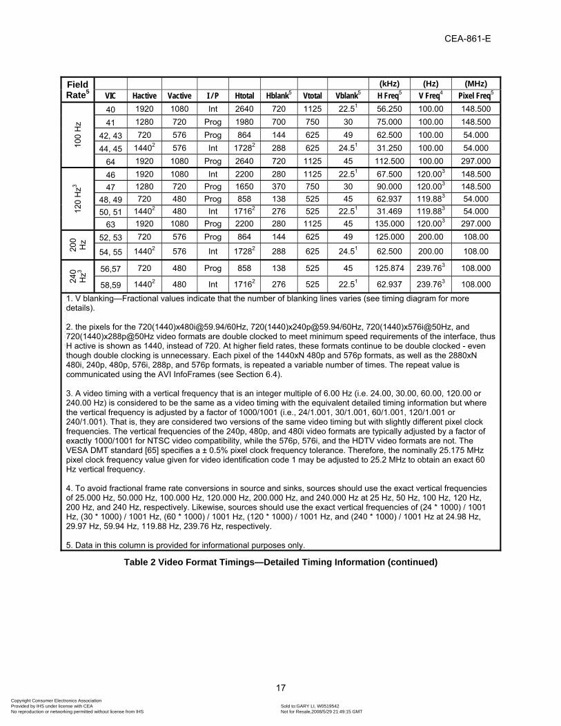
CEA-861-E
17
Field Rate5
(kHz) (Hz) (MHz) VIC Hactive Vactive I / P Htotal Hblank5 Vtotal Vblank5 H Freq5 V Freq4 Pixel Freq5
100
Hz
40 1920 1080 Int 2640 720 1125 22.51 56.250 100.00 148.500
41 1280 720 Prog 1980 700 750 30 75.000 100.00 148.500
42, 43 720 576 Prog 864 144 625 49 62.500 100.00 54.000
44, 45 14402 576 Int 17282 288 625 24.51 31.250 100.00 54.000
64 1920 1080 Prog 2640 720 1125 45 112.500 100.00 297.000
120
Hz3
46 1920 1080 Int 2200 280 1125 22.51 67.500 120.003 148.500 47 1280 720 Prog 1650 370 750 30 90.000 120.003 148.500
48, 49 720 480 Prog 858 138 525 45 62.937 119.883 54.000 50, 51 14402 480 Int 17162 276 525 22.51 31.469 119.883 54.000
63 1920 1080 Prog 2200 280 1125 45 135.000 120.003 297.000
200
Hz 52, 53 720 576 Prog 864 144 625 49 125.000 200.00 108.00
54, 55 14402 576 Int 17282 288 625 24.51 62.500 200.00 108.00
240
Hz3 56,57 720 480 Prog 858 138 525 45 125.874 239.763 108.000
58,59 14402 480 Int 17162 276 525 22.51 62.937 239.763 108.000
1. V blanking—Fractional values indicate that the number of blanking lines varies (see timing diagram for more details). 2. the pixels for the 720(1440)[email protected]/60Hz, 720(1440)[email protected]/60Hz, 720(1440)x576i@50Hz, and 720(1440)x288p@50Hz video formats are double clocked to meet minimum speed requirements of the interface, thus H active is shown as 1440, instead of 720. At higher field rates, these formats continue to be double clocked - even though double clocking is unnecessary. Each pixel of the 1440xN 480p and 576p formats, as well as the 2880xN 480i, 240p, 480p, 576i, 288p, and 576p formats, is repeated a variable number of times. The repeat value is communicated using the AVI InfoFrames (see Section 6.4). 3. A video timing with a vertical frequency that is an integer multiple of 6.00 Hz (i.e. 24.00, 30.00, 60.00, 120.00 or 240.00 Hz) is considered to be the same as a video timing with the equivalent detailed timing information but where the vertical frequency is adjusted by a factor of 1000/1001 (i.e., 24/1.001, 30/1.001, 60/1.001, 120/1.001 or 240/1.001). That is, they are considered two versions of the same video timing but with slightly different pixel clock frequencies. The vertical frequencies of the 240p, 480p, and 480i video formats are typically adjusted by a factor of exactly 1000/1001 for NTSC video compatibility, while the 576p, 576i, and the HDTV video formats are not. The VESA DMT standard [65] specifies a ± 0.5% pixel clock frequency tolerance. Therefore, the nominally 25.175 MHz pixel clock frequency value given for video identification code 1 may be adjusted to 25.2 MHz to obtain an exact 60 Hz vertical frequency. 4. To avoid fractional frame rate conversions in source and sinks, sources should use the exact vertical frequencies of 25.000 Hz, 50.000 Hz, 100.000 Hz, 120.000 Hz, 200.000 Hz, and 240.000 Hz at 25 Hz, 50 Hz, 100 Hz, 120 Hz, 200 Hz, and 240 Hz, respectively. Likewise, sources should use the exact vertical frequencies of (24 * 1000) / 1001 Hz, (30 * 1000) / 1001 Hz, (60 * 1000) / 1001 Hz, (120 * 1000) / 1001 Hz, and (240 * 1000) / 1001 Hz at 24.98 Hz, 29.97 Hz, 59.94 Hz, 119.88 Hz, 239.76 Hz, respectively. 5. Data in this column is provided for informational purposes only.
Table 2 Video Format Timings—Detailed Timing Information (continued)
Copyright Consumer Electronics Association Provided by IHS under license with CEA Sold to:GARY LI, W0519542
Not for Resale,2008/5/29 21:49:15 GMTNo reproduction or networking permitted without license from IHS
--``````,``,`,```,``,-`-`,,`,,`,`,,`---

CEA-861-E
18
Fiel
d R
ate
VIC
Fig
Hfro
nt
Hsyn
c
Hbac
k
Hpol
18
Vfro
nt
Vsyn
c
Vbac
k
Vpol
18
Ln
Refe
renc
e St
anda
rd
Note
s
Low
60 2 1760 40 220 P 5 5 20 P 1 SMPTE 296M [40] 1,2, 25 61 2 2420 40 220 P 5 5 20 P 1 SMPTE 296M [40] 1,2 62 2 1760 40 220 P 5 5 20 P 1 SMPTE 296M [40] 1,2 32 2 638 44 148 P 4 5 36 P 1 SMPTE 274M [2] 14
33 2 528 44 148 P 4 5 36 P 1 SMPTE 274M [2] 14
34 2 88 44 148 P 4 5 36 P 1 SMPTE 274M [2] 14
50H
z
17,18 1 12 64 68 N 5 5 39 N 1 ITU-R BT.1358 [56] 19 2 440 40 220 P 5 5 20 P 1 SMPTE 296M [40] 1,2
20 4 528 44 148 P 2 5 15 P 1 SMPTE 274M [2] 1,2 21,22 3 24 126 138 N 2 3 19 N 1 ITU-R BT.656–4 [54] 6, 15 23,24 1 24 126 138 N 222 3 19 N 1 ITU-R BT.1358 [56] 7, 14, 19 23,24 1 24 126 138 N 323 3 19 N 1 ITU-R BT.1358 [56] 7, 14, 15, 19 23,24 1 24 126 138 N 424 3 19 N 1 ITU-R BT.1358 [56] 7, 14, 15, 19 25,26 3 48 252 276 N 2 3 19 N 1 ITU-R BT.656–4 [54]17 8, 13, 14, 15 27,28 1 48 252 276 N 222 3 19 N 1 ITU-R BT.656–4 [54]17 7, 8, 12, 13,19
27,28 1 48 252 276 N 323 3 19 N 1 ITU-R BT.656–4 [54]17 7, 8, 12, 13,19
27,28 1 48 252 276 N 424 3 19 N 1 ITU-R BT.656–4 [54]17 7, 8, 12, 13,19
29,30 1 24 128 136 N 5 5 39 N 1 ITU-R BT.1358 [56] 9, 10, 14 31 2 528 44 148 P 4 5 36 P 1 SMPTE 274M [2] 14
37,38 1 48 256 272 N 5 5 39 N 1 ITU-R BT.1358 [56] 9, 11 39 5 32 168 184 P 23 5 57 N 1 AS 4933.1-2005 [67] 5
1 1 16 96 48 N 10 2 33 N 1 VESA DMT [65] 3, 4
60H
z
2,3 1 16 62 60 N 9 6 30 N 7 CEA-770.2-D [31] 2 4 2 110 40 220 P 5 5 20 P 1 CEA-770.3-C [32] 1,2 5 4 88 44 148 P 2 5 15 P 1 CEA-770.3-C [32] 1,2
6,7 3 38 124 114 N 4 3 15 N 4 CEA-770.2-D [31] 2, 15 8,9 1 38 124 114 N 420 3 15 N 4 CEA-770.2-D [31]17 7, 14, 15, 19 8,9 1 38 124 114 N 521 3 15 N 4 CEA-770.2-D [31]17 7, 14, 15, 19
10,11 3 76 248 228 N 4 3 15 N 4 CEA-770.2-D [31]17 8, 13 12,13 1 76 248 228 N 420 3 15 N 4 CEA-770.2-D [31]17 7, 8, 13, 19 12,13 1 76 248 228 N 521 3 15 N 4 CEA-770.2-D [31]17 7, 8, 13, 19 14,15 1 32 124 120 N 9 6 30 N 7 CEA-770.2-D [31] 9, 10, 13, 14
16 2 88 44 148 P 4 5 36 P 1 SMPTE 274M [2] 14 35,36 1 64 248 240 N 9 6 30 N 7 CEA-770.2-D [31] 9, 11
Table 3 Video Format Timings—Detailed Sync Information
Copyright Consumer Electronics Association Provided by IHS under license with CEA Sold to:GARY LI, W0519542
Not for Resale,2008/5/29 21:49:15 GMTNo reproduction or networking permitted without license from IHS
--``````,``,`,```,``,-`-`,,`,,`,`,,`---

CEA-861-E
19
Fi
eld
Rat
e
VIC
Fig
Hfro
nt
Hsyn
c
Hbac
k
Hpol
Vfro
nt
Vsyn
c
Vbac
k
Vpol
Ln
Refe
renc
e St
anda
rd
Note
s
100
Hz
40 4 528 44 148 P 2 5 15 P 1 SMPTE 274M [2]
41 2 440 40 220 P 5 5 20 P 1 SMPTE 296M [40]
42, 43 1 12 64 68 N 5 5 39 N 1 ITU-R BT.1358 [56]
44, 45 3 24 126 138 N 2 3 19 N 1 ITU-R BT.656–4 [54] 16
64 2 528 44 148 P 4 5 36 P 1 SMPTE 274M [2]
120
Hz
46 4 88 44 148 P 2 5 15 P 1 SMPTE 274M [2]
47 2 110 40 220 P 5 5 20 P 1 SMPTE 296M [40]
48, 49 1 16 62 60 N 9 6 30 N 7 CEA-770.2-D [31]
50, 51 3 38 124 114 N 4 3 15 N 4 CEA-770.2-D [31] 16
63 2 88 44 148 P 4 5 36 P 1 SMPTE 274M [2]
200
Hz 52, 53 1 12 64 68 N 5 5 39 N 1 ITU-R BT.1358 [56]
54, 55 3 24 126 138 N 2 3 19 N 1 ITU-R BT.656–4 [54] 16
240
Hz
56,57 1 16 62 60 N 9 6 30 N 7 CEA-770.2-D [31]
58,59 3 38 124 114 N 4 3 15 N 4 CEA-770.2-D [31] 16
Notes: 1. The reference standard uses tri-level sync, while CEA-861-E uses bi-level. Bi-level sync timing is accomplished using the second half of the reference standard’s tri-level sync, defining the actual sync time to be the rising edge of that pulse. 2. The reference standard uses a composite sync while CEA-861-E uses separate sync signals, thus eliminating the need for serrations during vertical sync. 3. VESA defines blanking as not including the border while CEA-861-E includes the border within the blanking interval. 4. Uses default IT color space, RGB components, and full range 8-bit color coding & quantization (see Section 5). 5. Is specifically designed for use with 31.25 kHz constant horizontal rate cathode-ray tube televisions and has a total of 1250 vertical lines – instead of the normal 1125 found in SMPTE 274 based timings. It has a frame, which is split into two unequal fields of 624.5 and 625.5 lines. The video format is specifically designed for use with special 31.25 kHz constant horizontal rate cathode-ray tube televisions and should be used with caution. Timing is similar to the 1250/50/2:1 system that described in Australian AS 4933.1-2005 standard [67]. 6. Same as the reference standard except for horizontal and vertical synchronization pulse durations, which are specified in ITU-R BT.711–1 [55] and ITU-R BT.470–6 [53]. Thus, the clock is 27 MHz. 7. There are two or three video frame timings that differ only in the number of blanking lines in the vertical blanking interval of the frame. All are considered variations of the same video timing. 8. Represents a superset of game console timings with variable repetition factors. Encompasses all of the following cases: a) 2880/10=288 pixels/line b) 2880/8=360 pixels/line c) 2880/7=411 pixels/line d) 2880/5=576 pixels/line e) 2880/4=720 pixels/line Typically has bars on the left and right sides that are 160/n pixels wide, where n is the repetition factor.
Copyright Consumer Electronics Association Provided by IHS under license with CEA Sold to:GARY LI, W0519542
Not for Resale,2008/5/29 21:49:15 GMTNo reproduction or networking permitted without license from IHS
--``````,``,`,```,``,-`-`,,`,,`,`,,`---

CEA-861-E
20
9. Represents a superset of timings with specific repetition factors that provide either additional bandwidth for carrying audio data or increased horizontal video resolution. 10. Is a superset of video formats encompassing all of the following cases: a) 1440/2=720 pixels/line b) 1440/1=1440 pixels/line 11. Is a superset of video formats encompassing all of the following cases: a) 2880/4=720 pixels/line b) 2880/2=1440 pixels/line c) 2880/1=2880 pixels/line 12. The exact video timing depends upon the pixel repetition factor specified in the AVI InfoFrame. 13. If this video timing is advertised in the EDID, the sink shall have an interface capable of signaling pixel repetition via AVI InfoFrames (e.g. HDMI) and shall accept all listed pixel repetition factors. 14. It is likely that non-HDMI sources may not recognize this video format in a Detailed Timing Descriptor. 15. Assumes the pixels are double-clocked to meet minimum clock speed requirements for the interface. 16. Assumes the pixels are double-clocked. 17. This is a "gaming" format. Progressive timing is obtained by removing the second field of the reference standard's interlace timing. 18. Hpol and Vpol stand for horizontal and vertical sync pulse polarity, respectively. The value ‘N’ signifies negative polarity, where the signal stays mostly high (at a logic ‘1’) and only pulses low (to a logic ‘0’) during the sync pulse. Likewise, the value ‘P’ signifies positive polarity, where the signal stays mostly low (at a logic ‘0’) and only pulses high (to a logic ‘1’) during the sync pulse. 19. Vfront varies as a function of Vtotal. 20. This value applies when Vtotal is 262 lines. 21. This value applies when Vtotal is 263 lines. 22. This value applies when Vtotal is 312 lines. 23. This value applies when Vtotal is 313 lines. 24. This value applies when Vtotal is 314 lines. 25. This video timing has been modified from the one listed in the reference standard. The reference standard specifies an odd Htotal greater than 4096, which is incompatible with legacy silicon. CEA-861-E instead uses the referenced standard's 720p30 video timing with a reduced pixel clock frequency to obtain 24Hz.
Table 3 Video Format Timings—Detailed Sync Information (continued)
Copyright Consumer Electronics Association Provided by IHS under license with CEA Sold to:GARY LI, W0519542
Not for Resale,2008/5/29 21:49:15 GMTNo reproduction or networking permitted without license from IHS
--``````,``,`,```,``,-`-`,,`,,`,`,,`---

CEA-861-E
21
Figure 1. General Progressive Video Format Timing (Negative Sync)
Copyright Consumer Electronics Association Provided by IHS under license with CEA Sold to:GARY LI, W0519542
Not for Resale,2008/5/29 21:49:15 GMTNo reproduction or networking permitted without license from IHS
--``````,``,`,```,``,-`-`,,`,,`,`,,`---

CEA-861-E
22
Figure 2. General Progressive Video Format Timing (Positive Sync)
Copyright Consumer Electronics Association Provided by IHS under license with CEA Sold to:GARY LI, W0519542
Not for Resale,2008/5/29 21:49:15 GMTNo reproduction or networking permitted without license from IHS
--``````,``,`,```,``,-`-`,,`,,`,`,,`---

CEA-861-E
23
Figure 3 General Interlaced Video Format Timing (Negative Sync)
Copyright Consumer Electronics Association Provided by IHS under license with CEA Sold to:GARY LI, W0519542
Not for Resale,2008/5/29 21:49:15 GMTNo reproduction or networking permitted without license from IHS
--``````,``,`,```,``,-`-`,,`,,`,`,,`---

CEA-861-E
24
Figure 4. General Interlaced Video Format Timing (Positive Sync)
Copyright Consumer Electronics Association Provided by IHS under license with CEA Sold to:GARY LI, W0519542
Not for Resale,2008/5/29 21:49:15 GMTNo reproduction or networking permitted without license from IHS
--``````,``,`,```,``,-`-`,,`,,`,`,,`---

CEA-861-E
25
Figure 5 Special Interlaced Video Format Timing (Even Vtotal)
Copyright Consumer Electronics Association Provided by IHS under license with CEA Sold to:GARY LI, W0519542
Not for Resale,2008/5/29 21:49:15 GMTNo reproduction or networking permitted without license from IHS
--``````,``,`,```,``,-`-`,,`,,`,`,,`---

CEA-861-E
26
4.1 Aspect Ratio A DTV should always indicate its native (physical) aspect ratio in the EDID version 1, revision 3 block’s “Max Horizontal Image Size” and “Max Vertical Image Size” fields even if the maximum image size is unknown or variable. Typically, the ratio of these two fields is 16:9 or 4:3 though this may not be true for some displays with non-standard aspect ratios. The source should use these fields to determine the native aspect ratio of the display. The 480p, 480i, 240p, 576p, 576i, and 288p formats are available in two different aspect ratios (4:3 and 16:9). Video formats with the same timing, but different picture aspect ratios are considered different formats that can be independently supported and discovered. These are referred to as dual-aspect ratio timings. For any dual-aspect ratio video timing, the Preferred Picture Aspect Ratio for that timing is indicated by the first listing of that timing in the EDID. When receiving a signal not accompanied by an aspect ratio indication (because no AVI InfoFrame is transmitted) a DTV shall assume that the aspect ratio is the Preferred Picture Aspect Ratio for the transmitted video timing. If a Dual Aspect Ratio DTV is receiving a video format timing for which it has declared support for both picture aspect ratios in EDID and the source has indicated the picture aspect ratio by including the AVI in the video stream, then the DTV shall display the picture in the aspect ratio that has been indicated by the source in the AVI. If the source does not support transmission of the AVI and the source supports both of the dual-aspect ratio video timing formats for a particular video timing defined by the sink, then the source shall provide the video to the DTV in the Preferred Picture Aspect Ratio. For a display device to simultaneously support both formats, the source needs a way to let the display device know the picture aspect ratio in which the video should be displayed. A DTV shall list only one picture aspect ratio of any dual-aspect ratio timing unless it is capable of receiving and decoding the AVI InfoFrame defined in Section 6. However, it is possible for a DTV that has no support for the AVI InfoFrame to still support both aspect ratios of such formats as a user programmable option. In that case, the EDID Detailed Timing Descriptor could be modified during operation to reflect the selected picture aspect ratio and the change could be signaled to the source (e.g. with Hot Plug Detect on DVI or HDMI). The effects on the EDID data structure are explained in Section 7.2.2. See Table 4 for Video ID Code and Aspect Ratios.
Copyright Consumer Electronics Association Provided by IHS under license with CEA Sold to:GARY LI, W0519542
Not for Resale,2008/5/29 21:49:15 GMTNo reproduction or networking permitted without license from IHS
--``````,``,`,```,``,-`-`,,`,,`,`,,`---

CEA-861-E
27
VIC Formats Field Rate Picture Aspect Ratio (H:V)1
Pixel Aspect Ratio (H:V)
1 640x480p 59.94Hz/60Hz 4:3 1:1 2 720x480p 59.94Hz/60Hz 4:3 8:9 3 720x480p 59.94Hz/60Hz 16:9 32:27 4 1280x720p 59.94Hz/60Hz 16:9 1:1 5 1920x1080i 59.94Hz/60Hz 16:9 1:1 6 720(1440)x480i 59.94Hz/60Hz 4:3 8:9 7 720(1440)x480i 59.94Hz/60Hz 16:9 32:27 8 720(1440)x240p 59.94Hz/60Hz 4:3 4:9 9 720(1440)x240p 59.94Hz/60Hz 16:9 16:27 10 2880x480i 59.94Hz/60Hz 4:3 2:9 – 20:92 11 2880x480i 59.94Hz/60Hz 16:9 8:27 -80:272 12 2880x240p 59.94Hz/60Hz 4:3 1:9 – 10:92 13 2880x240p 59.94Hz/60Hz 16:9 4:27 – 40:272 14 1440x480p 59.94Hz/60Hz 4:3 4:9 or 8:93 15 1440x480p 59.94Hz/60Hz 16:9 16:27 or 32:273 16 1920x1080p 59.94Hz/60Hz 16:9 1:1 17 720x576p 50Hz 4:3 16:15 18 720x576p 50Hz 16:9 64:45 19 1280x720p 50Hz 16:9 1:1 20 1920x1080i 50Hz 16:9 1:1 21 720(1440)x576i 50Hz 4:3 16:15 22 720(1440)x576i 50Hz 16:9 64:45 23 720(1440)x288p 50Hz 4:3 8:15 24 720(1440)x288p 50Hz 16:9 32:45 25 2880x576i 50Hz 4:3 2:15 – 20:152 26 2880x576i 50Hz 16:9 16:45-160:452 27 2880x288p 50Hz 4:3 1:15 – 10:152 28 2880x288p 50Hz 16:9 8:45 – 80:452 29 1440x576p 50Hz 4:3 8:15 or 16:153 30 1440x576p 50Hz 16:9 32:45 or 64:453 31 1920x1080p 50Hz 16:9 1:1 32 1920x1080p 23.97Hz/24Hz 16:9 1:1 33 1920x1080p 25Hz 16:9 1:1 34 1920x1080p 29.97Hz/30Hz 16:9 1:1 35 2880x480p 59.94Hz/60Hz 4:3 2:9, 4:9, or 8:94 36 2880x480p 59.94Hz/60Hz 16:9 8:27, 16:27, or 32:274 37 2880x576p 50Hz 4:3 4:15, 8:15, or 16:154 38 2880x576p 50Hz 16:9 16:45, 32:45, or 64:454 39 1920x1080i (1250 total) 50Hz 16:9 1:1
Table 4 Video Formats—Video ID Code and Aspect Ratios
Copyright Consumer Electronics Association Provided by IHS under license with CEA Sold to:GARY LI, W0519542
Not for Resale,2008/5/29 21:49:15 GMTNo reproduction or networking permitted without license from IHS
--``````,``,`,```,``,-`-`,,`,,`,`,,`---

CEA-861-E
28
VIC Formats Field Rate1 Picture Aspect Ratio (H:V)1
Pixel Aspect Ratio (H:V)
40 1920x1080i 100Hz 16:9 1:1 41 1280x720p 100Hz 16:9 1:1 42 720x576p 100Hz 4:3 16:15 43 720x576p 100Hz 16:9 64:45 44 720(1440)x576i 100Hz 4:3 16:15 45 720(1440)x576i 100Hz 16:9 64:45 46 1920x1080i 119.88/120Hz 16:9 1:1 47 1280x720p 119.88/120Hz 16:9 1:1 48 720x480p 119.88/120Hz 4:3 8:9 49 720x480p 119.88/120Hz 16:9 32:27 50 720(1440)x480i 119.88/120Hz 4:3 8:9 51 720(1440)x480i 119.88/120Hz 16:9 32:27 52 720x576p 200Hz 4:3 16:15 53 720x576p 200Hz 16:9 64:45 54 720(1440)x576i 200Hz 4:3 16:15 55 720(1440)x576i 200Hz 16:9 64:45 56 720x480p 239.76/240Hz 4:3 8:9 57 720x480p 239.76/240Hz 16:9 32:27 58 720(1440)x480i 239.76/240Hz 4:3 8:9 59 720(1440)x480i 239.76/240Hz 16:9 32:27 60 1280x720p 23.97Hz/24Hz 16:9 1:1 61 1280x720p 25Hz 16:9 1:1 62 1280x720p 29.97Hz/30Hz 16:9 1:1 63 1920x1080p 119.88/120Hz 16:9 1:1 64 1920x1080p 100Hz 16:9 1:1 65-127 Reserved for the Future
0 No Video Identification Code Available (Used with AVI InfoFrame only)
1. Picture Aspect Ratio—For example, with the 720x480 (16:9) data format and a 4:3 display, the source could (1) use pan and scan information to crop the data to 540 horizontal pixels and then resample up to the required 720 pixels for output to the display or (2) vertically resample to 360 lines and create bars of 60 lines above and below it to send this “letterbox” with the required 480 lines for output. Other picture scaling methods are possible in either source or sink. For example, picture aspect ratio scaling (picture expand, shrink, etc.) can be accomplished in the source, including, possibly, added black/gray lines in the pixel portion of the video. The exception to this is the 640x480 format, which is always sent as 4x3 data, and is rendered according to the characteristics of the sink. 2. The pixel repeat value can vary from 1 to 10 (see the PR field in Section 6.4) resulting in 10 variations of Pixel Aspect Ratio. 3. The pixel repeat value can vary from 1 to 2 (see the PR field in Section 6.4) resulting in 2 variations of Pixel Aspect Ratio. 4. The pixel repeat value can be 1, 2 to 4 (see the PR field in Section 6.4) resulting in 3 variations of Pixel Aspect Ratio.
Table 4 Video Formats—Video ID Code and Aspect Ratios (Continued)
1 In the case of interlaced formats, the frame rate is 1/2 the field rate.
Copyright Consumer Electronics Association Provided by IHS under license with CEA Sold to:GARY LI, W0519542
Not for Resale,2008/5/29 21:49:15 GMTNo reproduction or networking permitted without license from IHS
--``````,``,`,```,``,-`-`,,`,,`,`,,`---

CEA-861-E
29
4.2 Frame Rate Relationships Some video formats have a high frame rate that is an integer (2X, 4X, or 5X) multiple of the frame rate of a base (1X) video format. While receiving certain low frame rate video formats, some sources may calculate extra interpolated frames, and output a related high frame rate video format – in order to optimize display performance. Table 5 lists the VICs of base video formats along with the VICs of their higher frame rate counterparts.
Base (1X) 2X 4X 5X2 48 56 3 49 57 4 47 5 46 6 50 58 7 51 59 17 42 52 18 43 53 19 41 20 40 21 44 54 22 45 55 32 63 33 31 64 34 16 60 47 61 19 41 62 4 47
Table 5 Frame Rate Relationships—Base to High Frame Rate VICs
5 Color Encoding, Sampling, & Conversion
5.1 Default Encoding Parameters When present, encoding parameters specified in the AVI InfoFrame, or other interface-specific controls (e.g. HDMI General Control Packets), shall take precedence over any default parameters defined in this sub-section. The default component depth shall be 8-bits (N=8). Other elements of the default parameter set vary as a function of video format timing type (IT or CE) and (in the case of CE video format timings) vertical active line count (Vactive). When transmitting IT video format timings, the default color space shall be RGB using full range quantization levels. The RGB color space used for the transmission of IT video format timings should be the RGB color space the sink declares in the Basic Display Parameters and Feature Block of its EDID (see Sections A.2.6 and A.2.7 for further information). Most sources default to RGB color space when transmitting IT video format timings. If a source determines that a sink is incapable of receiving AVI InfoFrames or is incapable of receiving YCBCR pixel data, then it shall, by default, encode the CE video format pixel data in RGB color space using limited quantization range levels. If a sink is incapable of receiving AVI InfoFrames, incapable of receiving YCBCR pixel data, or does not receive an AVI InfoFrame, then it should, by default, assume CE video format pixel data is encoded in RGB color space using limited quantization range levels and IT video format pixel data is encoded in RGB color space using full quantization range levels. In all cases described above, the RGB color space used should be the RGB color space the sink declares in the Basic Display Parameters and Feature Block of its EDID.
Copyright Consumer Electronics Association Provided by IHS under license with CEA Sold to:GARY LI, W0519542
Not for Resale,2008/5/29 21:49:15 GMTNo reproduction or networking permitted without license from IHS
--``````,``,`,```,``,-`-`,,`,,`,`,,`---

CEA-861-E
30
If a source determines that a sink is capable of receiving AVI InfoFrames and is capable of receiving YCBCR pixel data, then it shall, by default, encode CE video format pixel data in a color space determined by the vertical active line count (Vactive) using limited quantization range levels. By default, an SD video format shall be encoded according to SMPTE 170M [1] color space and an HD video format shall be encoded according to ITU-R Rec. BT.709-5 [7] color space.
5.2 Color Component Samples Color is communicated using one of two sets of components: RGB and YCBCR
2. This interface shall be capable of supporting RGB (red, green, and blue), with encoding parameters based on the format. The interface may optionally support YCBCR.
5.2.1 RGB-to-YCBCR Conversion Matrices A transformation between YCBCR to RGB generally occurs within the DTV after it receives a YCBCR encoded picture. A transformation between YCBCR color component samples and RGB color component samples can be accomplished by applying one of two conversion matrices: ITU-R Rec. 601 [6] or ITU-R Rec. 709 [7]. The specific conversion matrix required depends on the Colorimetry and Extended Colorimetry fields in the AVI InfoFrame. The conversion matrix is either specified explicitly (i.e., the Colorimetry field is set to ITU-R BT.601 or ITU-R BT.709) or it is denoted in the subscript of the short name of the selected YCBCR colorimtery. For example, the ITU-R BT.601 conversion matrix applied to sYCC601 or AdobeYCC601 color component samples results in RGB color component samples (both positive and negative). The ITU-R BT.601-5 [6] Section 3.5 color space matrix is shown below for convenience. Y’= 0.299 R’ + 0.587 G’ + 0.114 B’ CR’ = ((R’ – Y’) * 0.71327) CB’ = ((B’ – Y’) * 0.56433) The ITU-R BT.709-5 [7] color conversion matrix is shown below for convenience. Y’= 0.2126 R’ + 0.7152 G’ + 0.0722 B’ CR’ = ((R’ – Y’) / 1.5748) CB’ = ((B’ – Y’) / 1.8556) Prime values are transformed levels in non-linear color space (see Transfer Characteristic section).
5.2.2 Sample Lattice In order to improve color reproduction, the sample lattice for RGB and YCBCR 4:2:2 pixel data should conform to the ITU-R Rec. 709 [7] sampling lattice. The sample lattice for these pixel data encodings are described below for convenience:
• R, G, B, and Y components are orthogonal, line- and picture-repetitive. R, G, and B components are co-sited with each other.
• CB and CR are orthogonal, line- and picture-repetitive co-sited with each other and with alternate
Y samples (starting with the first active Y sample in a line).
2 RGB signals have the same notation in the digital and analog domains. Typically, YCbCr notation is used for digital domains; and YPbPr is used for analog domains.
Copyright Consumer Electronics Association Provided by IHS under license with CEA Sold to:GARY LI, W0519542
Not for Resale,2008/5/29 21:49:15 GMTNo reproduction or networking permitted without license from IHS
--``````,``,`,```,``,-`-`,,`,,`,`,,`---

CEA-861-E
31
The sample lattice for YCBCR 4:4:4 pixel data should be the same as the sample lattice for RGB pixel data.
5.3 Transfer Characteristic (e.g. gamma correction) The transfer characteristics for sRGB (as specified in IEC 61966-2-1 [34]) encoded images are shown below for convenience. L’ = 12.92 * L for 0.0 ≤ L < 0.0031308 L’ = (1.055 * L^(1.0/2.4) ) – 0.055 for 0.0031308 ≤ L ≤ 1.000
Where: • L is the normalized component level in the range of 0.0 to 1.0 inclusive. • L’ is the transformed (gamma corrected) component level.
The transfer characteristics for sYCC (as specified in IEC 61966-2-1/Amendment.1:2003 [35]) encoded images are shown below for convenience. L'=-1.055 * L^(1.0/2.4) + 0.055 for L < -0.0031308 L'=12.92 * L for -0.0031308 <= L <= 0.0031308 L'=1.055 * L^(1.0/2.4) - 0.055 for 0.0031308 < L
Where: • L is the normalized component level.The lower and upper boundaries of this range may be less
than 0.0 (negative) and greater than 1.0, respectively. • L’ is the transformed (gamma corrected) component level.
The transfer characteristics for ITU-R Rec. BT.709 [7] and ITU-R Rec BT.601 [6]3 encoded images are shown below for convenience. L’ = 4.5 * L for 0.0 ≤ L < 0.018 L’ = (1.099 * L^(0.45) ) – 0.099 for 0.018 ≤ L ≤ 1.000
Where: • L is the normalized component level in the range of 0.0 to 1.0 inclusive. • L’ is the transformed (gamma corrected) component level.
The transfer characteristics of the image shall conform to IEC 61966-2-4 [5] when AVI InfoFrame Data Byte 2 indicates extended color gamut is used. The transfer characteristics for IEC 61966-2-4 [5] encoded images are shown below for convenience. Dynamic range compression of luminance components brighter than white (i.e., where L is greater than 1.0) should be avoided. L’ = (−1.099 * (-L)^(0.45) ) + 0.099 for L ≤ −0.018 L’ = 4.5 * L for -0.018 < L < 0.018 L’ = (1.099 * L^(0.45) ) − 0.099 for L ≥ 0.018
Where: • L is the normalized component level in a range defined by data transmitted in an interface specific
way according to the capabilities of the sink, which are identified by EDID bits MD[3:0] (see
3 ITU-R Rec. BT.601 [6] does not specify an actual transfer function, however, most DTVs are expected to be characterized to approximate the ITU-R Rec. BT.709 [7] transfer function.
Copyright Consumer Electronics Association Provided by IHS under license with CEA Sold to:GARY LI, W0519542
Not for Resale,2008/5/29 21:49:15 GMTNo reproduction or networking permitted without license from IHS
--``````,``,`,```,``,-`-`,,`,,`,`,,`---

CEA-861-E
32
section 7.5.5). The lower and upper boundaries of this range may be less than 0.0 (negative) and greater than 1.0, respectively.
• L’ is the transformed (gamma corrected) component level. The transfer characteristics for AdobeYCC601 and AdobeRGB (as specified in IEC 61966-2-5 [33]) encoded images are shown below for convenience. L' = L^(1.0/2.2) for 0 ≤ L ≤ 1.0
Where: • L is the normalized component level in the range of 0.0 to 1.0 inclusive. • L’ is the transformed (gamma corrected) component level.
5.4 Color Coding & Quantization Component Depth: The coding shall be N-bit, where N=8, 10, 12, or 16 bits/component - except in the case of the default 640x480 video timing 1, where the value of N shall be 8. Rounding: code = Floor (X + 0.5), where X is the result of a floating point calculation. Range: Limited range R, G, B, and Y signals shall have (219*2^(N-8))+1 quantization levels. Limited range CB and CR signals shall have (224*2^(N-8))+1 quantization levels. Full range R, G, B, and Y signals shall have (255*2^(N-8))+1 quantization levels. Levels: Limited range R, G, B, and Y signals shall have black level corresponding to code 16*2^(N-8) and the peak white level corresponding to code 235*2^(N-8); Limited range CB and CR signals shall have a zero level corresponding to digital code 2^(N-1) and range spanning codes 16*2^(N-8) to 240*2^(N-8). Overshoot/Undershoot Regions: If the N-bit digital video signal is converted to an analog signal in the sink, it is recommended that for RGB or Y, the black level (i.e., sync level and blanking level) be aligned with the video portion of the signal at black and white digital levels 16*2^(N-8) and 235*2^(N-8), respectively, such that the limited range digital signal swing corresponds to the nominal analog video swing (e.g. 0 to 700mV per sections 9.4, 10.5, and 10.6 of SMPTE 274M [2]). This means that zero analog level (0.0 IRE Units) should be associated with digital level 16*2^(N-8). Digital levels in an undershoot region 1 to (16*2^(N-8))-1 and overshoot region (235*2^(N-8))+1 to (2^N)-2 are recommended to be passed through the digital to analog converter; however, limited range of the analog signal should be aligned with the range 16*2^(N-8) to 235*2^(N-8) since it is expected that this range contains essential video. For the 640x480p format, it is recommended that the full 0-255 range be displayed for this format. Forbidden Values: For limited range R, G, B, Y, CB, CR signals, codes 0 and (2^N)-1 are reserved and should not be considered video.
6 ––Auxiliary Information Carried from Source to Sink Various types of auxiliary data can be carried from the source to the sink using InfoFrames. This section describes the InfoFrames that have been defined so far. The actual mechanism for carrying these InfoFrames may vary depending on the digital interface being used4.
4 Neither DVI 1.0 [4] nor OpenLDI 0.95 [8] contain a mechanism for transporting InfoFrames. These physical interfaces can be used to implement this standard with reduced functionality. HDMI, which is backward compatible
Copyright Consumer Electronics Association Provided by IHS under license with CEA Sold to:GARY LI, W0519542
Not for Resale,2008/5/29 21:49:15 GMTNo reproduction or networking permitted without license from IHS
--``````,``,`,```,``,-`-`,,`,,`,`,,`---

CEA-861-E
33
Source and sinks shall not rely on the Revision Number in the CEA Extension of the sink's EDID to determine whether a sink can accept InfoFrames. Sinks shall declare InfoFrame capability by including an interface related (e.g. HDMI) VSDB in their EDID CEA Extension. Sources shall only assume InfoFrame capability, when an appropriate (e.g. HDMI) VSDB is found.
NOTE—Previous versions of CEA-861 relied on a Revision Number in the included CEA Extension to indicate whether the sink could accept InfoFrames. Due to a significant number of DVI (not InfoFrame-capable) sinks having the Revision Number set to 3, indicating support of InfoFrames, and not being capable of doing so, it is necessary to deprecate this requirement.
DVI does not support the transmission of any InfoFrames, independent of CEA Extension version number. Sinks with a VSDB indicating support for reception of InfoFrames shall accept any of the InfoFrames defined here. Six types of InfoFrames are defined in CEA-861-E (Auxiliary Video Information InfoFrame, Vendor Specific InfoFrame, Source Product Description InfoFrame, Audio InfoFrame, MPEG Source InfoFrame, and NTSC VBI InfoFrame). The assigned type codes for these InfoFrames are shown in Table 6. The first byte of the InfoFrame designates the type of InfoFrame while the second byte indicates the version of that particular InfoFrame. All future versions of a specific InfoFrame shall be backward compatible with previous versions. They may contain additional information, but old and new devices should be able to access and interpret the information previously received.
Info Frame Type Code
Type of InfoFrame
0x00 Reserved 0x01 Vendor Specific (defined in Section 6.1) 0x02 Auxiliary Video Information (defined in Section 6.2) 0x03 Source Product Description (defined in Section 6.5) 0x04 Audio (defined in Section 6.6 of this document) 0x05 MPEG Source (defined in Section 6.7 of this document) 0x06 NTSC VBI (defined in Section 6.8 of this document)
0x07-0xFF Reserved for future use
Table 6 List of InfoFrame Type Codes The InfoFrame Length Field is contained in the third byte of each InfoFrame. This length field is the total number of bytes in the InfoFrame Payload. It does not include the Type, Version, or Length fields. In the case of the Vendor Specific InfoFrame, the length includes the IEEE Registration ID, also called "company_id" or OUI, as well as any additional bytes defined by the vendor to be in the InfoFrame (see Table 7). If the InfoFrame Length field is not set correctly, sinks might not be able to parse the InfoFrame correctly. The Vendor Specific InfoFrame is described in Section 6.1.The contents of the Auxiliary Video Information InfoFrame are described in Section 6.2. The contents of the Product Description InfoFrame are described in Section 6.5. The contents of the Audio InfoFrame are described in Section 6.6. The contents of the MPEG Source InfoFrame are described in Section 6.7. The contents of the NTSC VBI InfoFrame are described in Section 6.8.
6.1 Vendor Specific InfoFrames The content of the Vendor Specific InfoFrame is defined in Table 7. This InfoFrame can be used by product manufacturers or organizations that have an assigned 24-bit IEEE Registration Identifier to transport information not defined elsewhere. The Vendor Specific Payload would be defined by the
with DVI 1.0 and contains mechanisms for transferring InfoFrames, digital audio, and YCBCR pixel data, is available and can be used to implement the full capabilities of CEA-861-E.
Copyright Consumer Electronics Association Provided by IHS under license with CEA Sold to:GARY LI, W0519542
Not for Resale,2008/5/29 21:49:15 GMTNo reproduction or networking permitted without license from IHS
--``````,``,`,```,``,-`-`,,`,,`,`,,`---

CEA-861-E
34
organization to which the 24-bit IEEE number refers. The 24-bit IEEE number is sent the least significant byte first. It is recommended that the Vendor Specific Payload contain a “length field” to facilitate extensibility, but this is not required. Any organization or vendor that wishes to define a vendor specific InfoFrame shall obtain a registration ID (also known as vendor ID, organizationally unique ID or company ID) from the IEEE Registration Authority [71].
Byte # Field Name Contents n Vendor Specific
InfoFrame Type Code 0x01
n+1 Vendor Specific InfoFrame Version
0x01
n+2 LV InfoFrame Length
Total number of bytes in InfoFrame Payload including IEEE Registration ID
n+3 24 bit IEEE Registration Identifier
24 bit IEEE Registration ID (Least Significant Byte first) ....
n+5 ... Vendor Specific Payload Vendor Specific Payload n+LV-1
Table 7 Vendor Specific InfoFrame
6.2 Auxiliary Video Information (AVI) InfoFrame The Auxiliary Video Information (AVI) InfoFrame contains information that describes the pixel data carried in the next video field. It also contains information about the composition of the picture. Also see Section 7 for EDID requirements that relate to the processing of AVI InfoFrames in both source and sinks.
NOTE—Previous versions of CEA-861 defined the Version 1 AVI InfoFrame. Support for version 1 is not included in CEA-861-E.
Sources shall not use AVI InfoFrame version 1. If the source supports the transmission of the Auxiliary Video Information (AVI) and if it determines that the sink is capable of receiving that information, it shall send the AVI to the sink once per video field. The data applies to the next full frame of video data. A sink capable of receiving a video format with video identification code greater than 7 or capable of receiving dual-aspect ratio timing shall be able to receive and decode the AVI InfoFrame described in this Section. As required in Section 7.1, a sink declares the capability of receiving video formats generated at different picture aspect ratios by listing both video formats in its EDID data structure. Simultaneous support of timings available in two different aspect ratios shall be indicated by listing both formats in the EDID data structure at the same time. If, for some reason, an indication is received that conflicts with the video format being received (e.g., the source indicates 4:3 but sends the 1920x1080i format), then the sink shall ignore the conflicting information in the AVI. If a sink is capable of receiving YCBCR pixel data, then, as defined in Section 7.1, it is required to include the Version 3 CEA Extension in its EDID with at least one of the YCBCR chroma sampling format bits set. When a sink's EDID indicates that it is capable of receiving YCBCR pixel data the sink shall be capable of receiving AVI InfoFrames. If no AVI InfoFrame is sent from the source, then, as defined in Section 5.1, the sink is required to assume that all CE video formats are encoded in RGB color space using limited quantization range levels with an 8-bit component depth. The information on “Active Format Aspect Ratio,” bar widths, overscan/underscan, non-uniform picture scaling, and colorimetry is information that can be used by the sink to improve the picture quality. Use of
Copyright Consumer Electronics Association Provided by IHS under license with CEA Sold to:GARY LI, W0519542
Not for Resale,2008/5/29 21:49:15 GMTNo reproduction or networking permitted without license from IHS
--``````,``,`,```,``,-`-`,,`,,`,`,,`---

CEA-861-E
35
this information by the sink is optional. If this information is present at the source and valid5, and if the sink is capable of receiving the AVI, the source shall send the information.
6.3 Format of Version 1 AVI InfoFrame The Version 1 AVI InfoFrame was originally defined in a predecessor of CEA-861-E but not used. For historical purposes, the Version 1 AVI InfoFrame is shown in Table 8. InfoFrame Type Code InfoFrame Type = 0x02
InfoFrame Version Number Version = 0x01
Length of AVI InfoFrame Length of AVI InfoFrame (13)
Data Byte 1 F17=0 Y1 Y0 A0 B1 B0 S1 S0
Data Byte 2 C1 C0 M1 M0 R3 R2 R1 R0
Data Byte 3 F37=0 F36=0 F35=0 F34=0 F33=0 F32=0 SC1 SC0
Data Byte 4 F47=0 F46=0 F45=0 F44=0 F43=0 F42=0 F41=0 F40=0
Data Byte 5 F57=0 F56=0 F55=0 F54=0 F53=0 F52=0 F51=0 F50=0
Data Byte 6 ETB07-ETB00 (Line Number of End of Top Bar – lower 8 bits)
Data Byte 7 ETB15-ETB08 (Line Number of End of Top Bar –upper 8 bits)
Data Byte 8 SBB07-SBB00 (Line Number of Start of Bottom Bar – lower 8 bits)
Data Byte 9 SBB15-SBB08 (Line Number of Start of Bottom Bar - upper 8 bits)
Data Byte 10 ELB07-ELB00 (Pixel Number of End of Left Bar – lower 8 bits)
Data Byte 11 ELB15-ELB08 (Pixel Number of End of Left Bar – upper 8 bits)
Data Byte 12 SRB07-SRB00 (Pixel Number of Start of Right Bar – lower 8 bits)
Data Byte 13 SRB15-SRB08 (Pixel Number of Start of Right Bar – upper 8 bits)
Table 8 Auxiliary Video Information InfoFrame format (Version 1)
6.4 Format of Version 2 AVI InfoFrame The format of the Version 2 AVI InfoFrame is backward compatible with Version 1. All of the fields that were contained in the Version 1 AVI InfoFrame are also contained in the Version 2 AVI InfoFrame. Their purpose and use remain unchanged. All fields of the Version 2 AVI are described here. The Version 2 AVI InfoFrame is shown in Table 9.
5 The data may not be valid if, for example, the stream was converted from an analog signal with no reliable aspect ratio or format information.
Copyright Consumer Electronics Association Provided by IHS under license with CEA Sold to:GARY LI, W0519542
Not for Resale,2008/5/29 21:49:15 GMTNo reproduction or networking permitted without license from IHS
--``````,``,`,```,``,-`-`,,`,,`,`,,`---

CEA-861-E
36
InfoFrame Type Code InfoFrame Type = 0x02
InfoFrame Version Number Version = 0x02
Length of AVI InfoFrame Length of AVI InfoFrame (13)
Data Byte 1 F17=0 Y1 Y0 A0 B1 B0 S1 S0
Data Byte 2 C1 C0 M1 M0 R3 R2 R1 R0
Data Byte 3 ITC EC2 EC1 EC0 Q1 Q0 SC1 SC0
Data Byte 4 F47=0 VIC6 VIC5 VIC4 VIC3 VIC2 VIC1 VIC0
Data Byte 5 YQ1 YQ0 CN1 CN0 PR3 PR2 PR1 PR0
Data Byte 6 ETB07-ETB00 (Line Number of End of Top Bar – lower 8 bits)
Data Byte 7 ETB15-ETB08 (Line Number of End of Top Bar – upper 8 bits)
Data Byte 8 SBB07-SBB00 (Line Number of Start of Bottom Bar – lower 8 bits)
Data Byte 9 SBB15-SBB08 (Line Number of Start of Bottom Bar – upper 8 bits)
Data Byte 10 ELB07-ELB00 (Pixel Number of End of Left Bar – lower 8 bits)
Data Byte 11 ELB15-ELB08 (Pixel Number of End of Left Bar – upper 8 bits)
Data Byte 12 SRB07-SRB00 (Pixel Number of Start of Right Bar – lower 8 bits)
Data Byte 13 SRB15-SRB08 (Pixel Number of Start of Right Bar – upper 8 bits)
Table 9 Auxiliary Video Information (AVI) InfoFrame Format (Version 2) Data Byte 1 (Table 10) contains bits that describe overscan/underscan (e.g., computer graphics or video), two bits to indicate the color component sample format and chroma sampling, and other bits to indicate the presence of active format and/or bar data. If the bar data and the active format information do not agree, then the bar data shall take precedence. Data Byte 1, bits Y1, and Y0 set the color component sample format and chroma sampling format of the next picture. The source shall first determine if the sink is capable of receiving YCBCR pixel data in the defined chroma sampling format prior to sending such data. See Sections 7.1 and 7.4 for a description of a sink's support of YCBCR chroma sampling formats. Data Byte 1, bit A0 indicates whether Active Format Data is present in Data Byte 2 bits R3 through R0. A source device shall set A0=1 when any of the AFD bits are set. Data Byte 1, bits B1, and B0 indicate the presence and type of bar data transmitted in Data Bytes 6 through 13. The contents of Data Bytes 6 through 13 are described later in this Section. The presence of both vertical and horizontal bar data is not standardized.
Copyright Consumer Electronics Association Provided by IHS under license with CEA Sold to:GARY LI, W0519542
Not for Resale,2008/5/29 21:49:15 GMTNo reproduction or networking permitted without license from IHS
--``````,``,`,```,``,-`-`,,`,,`,`,,`---

CEA-861-E
37
F7 Future Use, all Zeros
Y1 Y0 RGB or YCBCR
A0 Active Format
Information Present
B1 B0 Bar Data Present
S1 S0 Scan Information
0 0 0 RGB
(default)
0 No Active Format
Information
0 0 Bar Data not
present
0 0 No Data
0 1 YCBCR
4:2:2
1 Active Format (R3…R0)
Information present
0 1 Vert. Bar Info
present
0 1 Composed for an overscanned display, where some active pixels and lines at the edges are not displayed.
1 0 YCBCR
4:4:4
1 0 Horiz. Bar Info present
1 0 Composed for an underscanned display, where all active pixels & lines are displayed, with or without a border.
1 1 Future 1 1 Vert. and Horiz.
Bar Info present
1 1 Future
Table 10 AVI InfoFrame Data Byte 1 Data Byte 1, bits S1, and S0 contain information that defines the picture composition of the next video field. A source shall set S=1 (S1=0, S0=1) or S=2 (S1=1, S0=0) if it is confident of the accuracy of those values. Otherwise, it shall set S=0 (no data). The source shall follow these rules for setting S even in the absence of an indication that the sink responds to the value of S. Data Byte 2, bits M1, and M0 contain the Picture Aspect Ratio. If M=0 (M1=0, M0=0), a sink shall assume the picture is formatted according to the preferred picture aspect ratio. A sink should adjust its scan based on the value of S. A sink would overscan if it received S=1, and underscan if it received S=2. If it receives S=0, then it should overscan for a CE video format and underscan for an IT video format. A sink should indicate its overscan/underscan behavior using a Video Capabilities Data Block (see Section 7.5.6). Data Byte 2 (Table 11) contains bits that describe colorimetry, picture aspect ratio, and active format information. Data Byte 2, C0, and C1 are used in conjunction with Data Byte 3, EC0 through EC2 to override the default color spaces and explicitly indicate the colorimetry of the next picture. If bits C0 and C1 are zero, the colorimetry shall correspond to the default colorimetry defined in Section 5.1. A source shall be prohibited from setting C=1 (C1=0, C0=1) or C=2 (C1=1, C0=0) when Y=0 (Y1=0, Y0=0) in Data Byte 1. C=3 shall be reserved for future use.
Copyright Consumer Electronics Association Provided by IHS under license with CEA Sold to:GARY LI, W0519542
Not for Resale,2008/5/29 21:49:15 GMTNo reproduction or networking permitted without license from IHS
--``````,``,`,```,``,-`-`,,`,,`,`,,`---

CEA-861-E
38
C1 C0 Colorimetry M1 M0 Coded Frame Aspect Ratio
R3 R2 R1 R0 Active Portion Aspect Ratio
0 0 No Data 0 0 No Data 1 0 0 0 Same as coded frame aspect ratio
0 1 SMPTE 170M [1]
0 1 4:3 1 0 0 1 4:3 (Center)
1 0 ITU-R 709 [7] 1 0 16:9 1 0 1 0 16:9 (Center)
1 1 Extended Colorimetry Information Valid (colorimetry indicated in bits EC0, EC1, EC2. See Table 11)
1 1 Future 1 0 1 1 14:9 (Center)
other values Varies. See Annex H.
Table 11 AVI InfoFrame Data Byte 2 Table 12 illustrates the terminology and examples of common aspect ratio information that can be communicated from a source to a display device using CEA-861-E. It illustrates some of the possibilities for the two standard picture aspect ratios (4:3 and 16:9) within the coded frame. The “active format” codes shall be shall be transmitted when received with content. Originating devices supplying such codes may provide codes in accordance with the Active Format Description6 (AFD) in ETSI TS 101 154 [47]. All of the active format codes defined in [47] are reproduced in informative Annex H.
6 Note that the use of the word “active” in the “Active Format Description” differs from how it is used in other places of this standard and documents referenced by this standard. The word, “active” usually refers to all active pixels. In this case of AFD, the word, “active” refers only to the area containing content pixels and its format relative to areas potentially containing bar pixels.
Copyright Consumer Electronics Association Provided by IHS under license with CEA Sold to:GARY LI, W0519542
Not for Resale,2008/5/29 21:49:15 GMTNo reproduction or networking permitted without license from IHS
--``````,``,`,```,``,-`-`,,`,,`,`,,`---

CEA-861-E
39
active_format Description
4:3 coded frames 16:9 coded frames
‘1000’ 4:3 full frame image
16:9 full frame image
‘1001’ 4:3 full frame image
4:3 pillarbox image
‘1010’ 16:9
letterbox image
16:9 full frame image
‘1011’ 14:9
letterbox image
14:9 pillarbox image
Table 12 Common Active Formats See CEA-CEB16 [46] for more information about AFD processing. Data Byte 3 is divided into four fields as shown in Table 13.
ITC
IT content
EC2
EC1
EC0 Extended
Colorimetry
Q1
Q0
RGB Quantization Range
SC
1 SC
0 Non-Uniform Picture Scaling
0 No data 0 0 0 xvYCC601 0 0 Default (depends on video format)
0 0 No Known non-uniform Scaling
1 IT content (Byte 5 CN bits valid)
0 0 1 xvYCC709 0 1 Limited Range 0 1 Picture has been scaled horizontally
0 1 0 sYCC601 1 0 Full Range 1 0 Picture has been scaled vertically
0 1 1 AdobeYCC601 1 1 Reserved 1 1
Picture has been scaled horizontally and vertically
1 0 0 AdobeRGB
All other values reserved
Table 13 AVI InfoFrame Data Byte 3 Bits SC1 and SC0 provide information on whether the picture has been scaled in a non-uniform way (i.e., unequal along horizontal and vertical dimensions) prior to transmission to the sink. The Non-uniform Picture Scaling bits shall be set if the source scales the picture or has determined that scaling has been performed in a specific direction. If the picture has been stretched or shrunk in a uniform way (i.e., equally along both dimensions), then the bits should not be set. These bits are present to help avoid situations such as the one illustrated in Annex I.
Copyright Consumer Electronics Association Provided by IHS under license with CEA Sold to:GARY LI, W0519542
Not for Resale,2008/5/29 21:49:15 GMTNo reproduction or networking permitted without license from IHS
--``````,``,`,```,``,-`-`,,`,,`,`,,`---

CEA-861-E
40
Displays conforming to CEA-861-E accept both limited and full range quantization range pixel data when receiving pictures encoded in an RGB color space. The quantization bits in Data Byte 3, bits Q1 and Q0 allow the source to override the default RGB quantization range and to explicitly indicate the RGB quantization range of the next picture. The value Q=0 (Q1=0, Q0=0) indicates that the quantization range corresponds to the default RGB quantization range defined in Section 5.1. A source shall not send a non-zero Q value that does not correspond to the default RGB quantization range for the transmitted picture unless the sink indicates support for the Q bit in a Video Capabilities Data Block (see Section 7.5.6). The IT content bit indicates when picture content is directly composed according to common IT practices or derived from a specific type of IT content. When the IT content bit is set to 1, downstream processors should process pixel data according to the setting of the content type bits CN1 and CN0 of Byte 5. The following rules apply to the ITC flag: if ITC = 0, the Content flags (CN0, CN1) should be ignored; if ITC = 1, the Content flags (CN0, CN1) are valid and shall be interpreted according Table 16.
RGB or YCBCR (from
Data Byte 1)
Colorimetry (from Data
Byte 2) Extended Colorimetry
(from Data Byte 3) Colorimetry of Next Transmitted Picture Notes
Y1 Y0 C1 C0 EC2 EC1 EC0
RGB 4:4:4
0 0 0 0 X X X RGB 1 0 0 0 1 X X X Reserved 0 0 1 0 X X X Reserved 0 0 1 1 0 X X Reserved
0 0 1 1 1 0 0 AdobeRGB 2 0 0 1 1 1 0 1 Reserved 0 0 1 1 1 1 0 Reserved 0 0 1 1 1 1 1 Reserved
YCBCR 4:2:2
0 1 0 0 X X X SMPTE 170M [1] or ITU-R Rec. BT.709
[7] 3,4
0 1 0 1 X X X SMPTE 170M [1] 4
0 1 1 0 X X X ITU-R Rec. BT.709 [7] 4
0 1 1 1 0 0 0 xvYCC601 2,4 0 1 1 1 0 0 1 xvYCC709 2,4 0 1 1 1 0 1 0 sYCC601 2,4 0 1 1 1 0 1 1 AdobeYCC601 2,4 0 1 1 1 1 X X Reserved
YCBCR 4:4:4
1 0 0 0 X X X SMPTE 170M [1] or ITU-R Rec. BT.709
[7] 3,4
1 0 0 1 X X X SMPTE 170M [1] 4
1 0 1 0 X X X ITU-R Rec. BT.709 [7] 4
1 0 1 1 0 0 0 xvYCC601 2,4 1 0 1 1 0 0 1 xvYCC709 2,4 1 0 1 1 0 1 0 sYCC601 2,4 1 0 1 1 0 1 1 AdobeYCC601 2,4 1 0 1 1 1 X X Reserved
Future 1 1 X X X X X Reserved Notes: 1. A DTV declares it is capable of displaying pictures encoded in sRGB color space (as defined in IEC 61996-2-1 [34]) by setting bit 2 in the Feature Support byte (0x18) of the Basic Display Parameters and Feature Block in its EDID. A sink that declares it is not capable of displaying pictures encoded in RGB color space declares its colorimetry via the values set in bytes 0x19 through 0x22 of the Basic
Copyright Consumer Electronics Association Provided by IHS under license with CEA Sold to:GARY LI, W0519542
Not for Resale,2008/5/29 21:49:15 GMTNo reproduction or networking permitted without license from IHS
--``````,``,`,```,``,-`-`,,`,,`,`,,`---

CEA-861-E
41
Display Parameters and Feature Block in its EDID. See sections A.2.6 and A.2.7 for further information. 2. A DTV declares it is capable of displaying pictures encoded in this colorimetry by setting the associated bit in Byte 3 of the Colorimetry Data Block in its EDID. See section 7.5.5 for further information. 3. The picture colorimetry is dependent on the value of Vactive for the Video Identification Code set in the AVI InfoFrame. See Section 5 for further information. 4. A DTV declares it is capable of displaying pictures encoded in this colorimetry by setting bit 4 and/or bit 5 in Byte 3 of the CEA Extension Version 3 block in its EDID. See section 7.5.
Table 14 Picture Colorimetry Indicated by the RGB or YCBCR (Y), Colorimetry (C) and Extended Colorimetry (EC) Field Settings
Bits 0 through 6 of byte 4 contain a Video Identification Code (VIC). In most cases, the video format can be uniquely determined from the video format timing itself. However, if the source is sending one of the video formats defined in this document, then it shall set this field to the proper code. If a video format not listed in CEA-861-E is sent, then the Video Identification Code shall be set to 0. If this field is used and if it is inconsistent with the video format being received, then it shall be ignored by the sink. If the picture aspect ratio implied by this field does not agree with the picture aspect ratio communicated in Data Byte 2, then Data Byte 2 shall take precedence. The codes associated with each video format are shown in Table 4. These same codes are used in the Short Video Descriptors used in the Version 3 CEA Extension, which is described in Section 7.5. If the source needs to convey “no information” regarding the video format (perhaps it is sending a proprietary format that was defined using the EDID Detailed Timing Descriptor in the sink), then this field shall be set to 0. Data Byte 5 contains the pixel repetition field (PR). The first transmitted active pixel of an active line shall be unique. When PR is zero, the second through the last transmitted active pixel shall each be unique. When PR is greater than zero, unique active pixels are transmitted less often as the source shall repeat each unique active pixel PR-times. Unique active pixels are always vertically aligned and horizontally spaced at PR+1 active pixel (clock) intervals. The values for PR are shown in Table 15. When Photo content is sent by the source, Byte 5 Content bits CN1 and CN0 shall be set to Photo (CN1=0 and CN0=1), this setting shall be used in conjunction with Byte 4 to indicate the color space for Photo content which is either sYCC601, AdobeYCC601, or AdobeRGB.
PR3 PR2 PR1 PR0 Pixel Repetition Factor (PR+1) 0 0 0 0 No Repetition (i.e., pixel date sent once) 0 0 0 1 pixel data sent 2 times (i.e., repeated once) 0 0 1 0 pixel data sent 3 times 0 0 1 1 pixel data sent 4 times 0 1 0 0 pixel data sent 5 times 0 1 0 1 pixel data sent 6 times 0 1 1 0 pixel data sent 7 times 0 1 1 1 pixel data sent 8 times 1 0 0 0 pixel data sent 9 times 1 0 0 1 pixel data sent 10 times
0x0A-0x0F Reserved
Table 15 AVI InfoFrame Pixel Repetition Field, Data Byte 5 A source shall correctly set the PR field whenever it sends an AVI InfoFrame to a sink – no matter what video timing format is being transmitted. A list of allowable PR values for each CE video format is shown in Table 18. Note that this characteristic is independent of Picture Aspect Ratio. When a source outputs a
Copyright Consumer Electronics Association Provided by IHS under license with CEA Sold to:GARY LI, W0519542
Not for Resale,2008/5/29 21:49:15 GMTNo reproduction or networking permitted without license from IHS
--``````,``,`,```,``,-`-`,,`,,`,`,,`---

CEA-861-E
42
video timing format with non-repeated pixels, PR shall be set to 0. When a source outputs a double-clocked video timing format, PR shall be set to 1. When a source outputs video timing formats 10 through 15, 25 through 30, or 35 through 38, it shall send an AVI InfoFrame indicating the specific PR being used and the sink shall properly interpret it – decimating or repeating pixels depending on the signal process. Video timing formats with Video Identification Codes 10 through 15, 25 through 30, and 35 through 38 support variable horizontal resolution.These video formats maintain a fixed 1440- or 2880-pixel Hactive and use pixel repetition to, in effect, provide different horizontal resolutions. Video formats with video identification codes 10 through 13 and 25 through 28 keep Hactive fixed at 2880 pixels and allow PR to be varied over a 10-to-1 range thereby providing effective resolutions of 288, 320, 360, 411, 480, 576, 720, 960, 1440, and 2880 unique active pixels per video line, respectively. In addition, gaming formats typically utilize optional left and right bars, which insure that all of the pixels in a game are visible on overscanned displays and further reduce the number of content pixels to 256, 284, 320, 366, 427, 512, 640, 853, 1280, and 2560 pixels, respectively. When Hactive is not an integer multiple of PR+1, the source shall adjust the sidebars so that the width of the left bar is an integer multiple of PR+1 and the right bar begins with a unique active pixel. Table 19 gives recommended bar placement for each value of PR in the form of AVI bar data. Video formats with video identification codes 14, 15, 29, and 30 allow PR to be set to 2 or 1 thereby providing effective resolutions of 720 or 1440 unique active pixels per video line, respectively. Video formats with video identification codes 35 through 38 allow PR to be set to 4, 2, or 1 thereby providing effective resolutions of 720, 1440, or 2880 unique active pixels per video line, respectively. The extended colorimetry bits, EC2, EC1, and EC0, describe optional colorimetry encoding that may be applicable to some implementations. The sink shall interpret the Y, C, and EC fields of Data Bytes 1, 2 and 3 according to Table 14. A value of 'X' in the table indicates the bit shall be ignored by the sink. A reserved value in the table means the colorimetry assumed by the sink is indeterminate. Sources shall be prohibited from setting reserved colorimetries.
CN1 CN0 IT Content Type0 0 Graphics 0 1 Photo 1 0 Cinema 1 1 Game
Table 16 AVI Info Frame IT Contents Type, Data Byte 5 Table 16 illustrates the meaning of Data Byte 5 Content Type bits CN1 and CN0. These bits should be used to signal delivery of IT content that is either classified as Graphics, Photo, Cinema, or Game. The Graphics type is indicated by the source to flag content composed according to common IT practice (i.e. without regard to Nyquist criterion) and is unsuitable for analog reconstruction or filtering. In IT applications (e.g. involving bit mapped text), each pixel in the source’s frame buffer is most clearly displayed if it is directly mapped to a light-emitting pixel on the display device - such that adjacent pixels are completely independent and do not interact. When the IT content bit is set to 1 and the Graphics type is indicated, downstream processors should pass pixel data unfiltered and without analog reconstruction. The Photo type is indicated by the source to flag content derived from digital still pictures; sources may be a digital still camera, DVD player or other device. When the Photo type is indicated, an additional flag for Extended Colorimetry should correctly account for the content’s color space. When the IT content bit is set to 1 and the Photo type is indicated, the sink is expected to “pass through” still pictures with minimal scaling and picture enhancement in order to avoid undesirable artifacts. The Photo type should not be associated with device type. For example, digital still cameras may support delivery of video.
Copyright Consumer Electronics Association Provided by IHS under license with CEA Sold to:GARY LI, W0519542
Not for Resale,2008/5/29 21:49:15 GMTNo reproduction or networking permitted without license from IHS
--``````,``,`,```,``,-`-`,,`,,`,`,,`---

CEA-861-E
43
The Cinema type is indicated by the source to flag content derived from cinema material. Audio may be processed through an audio video amplifier (AV Amp) or digital television. When the IT content bit is set to 1 and the Cinema type is indicated, the sink should “pass through” cinema content with minimal scaling and picture enhancement in order to avoid undesirable artifacts. The Cinema type should not be associated with device type. For example, DVD players are capable of supplying various content types such as TV programs. The Game type is indicated by the source to flag content derived from game machine material. When the IT content bit is set to 1 and the Game type is indicated, the sink should “pass through” game content with minimal scaling and picture enhancement in order to avoid undesirable artifacts. Audio and video latency should also be minimized. The Game type should not be associated with device type. For example, game machines are capable of supplying various content types such as DVD movies.
YQ1 YQ0 YCC Quantization Range 0 0 Limited Range 0 1 Full Range 1 0 Reserved 1 1 Reserved
Table 17 AVI Info Frame YCC Quantization Range, Data Byte 5 Table 17 illustrates the meaning assigned to the YCC Quantization Range bits YQ1 and YQ0 in Data Byte 5.
Copyright Consumer Electronics Association Provided by IHS under license with CEA Sold to:GARY LI, W0519542
Not for Resale,2008/5/29 21:49:15 GMTNo reproduction or networking permitted without license from IHS
--``````,``,`,```,``,-`-`,,`,,`,`,,`---

CEA-861-E
44
VIC Video Description Valid Pixel Repeat Values AVI w/PR Required
1 640x480p @ 59.94/60Hz No Repetition No 2, 3 720x480p @ 59.94/60Hz No Repetition No 4 1280x720p @ 59.94/60Hz No Repetition No 5 1920x1080i @ 59.94/60Hz No Repetition No 6, 7 720(1440)x480i @ 59.94/60Hz pixel data sent 2 times No 8, 9 720(1440)x240p @ 59.94/60Hz pixel data sent 2 times No 10, 11 2880x480i @ 59.94/60Hz pixel data sent 1 to 10 times Yes 12, 13 2880x240p @ 59.94/60Hz pixel data sent 1 to 10 times Yes 14, 15 1440x480p @ 59.94/60Hz pixel data sent 1 to 2 times Yes 16 1920x1080p @ 59.94/60Hz No Repetition No 17, 18 720x576p @ 50Hz No Repetition No 19 1280x720p @ 50Hz No Repetition No 20 1920x1080i @ 50Hz No Repetition No 21, 22 720(1440)x576i @ 50Hz pixel data sent 2 times No 23, 24 720(1440)x288p @ 50Hz pixel data sent 2 times No 25, 26 2880x576i @ 50Hz pixel data sent 1 to 10 times Yes 27, 28 2880x288p @ 50Hz pixel data sent 1 to 10 times Yes 29, 30 1440x576p @ 50Hz pixel data sent 1 or 2 times Yes 31 1920x1080p @ 50Hz No Repetition No 32 1920x1080p @ 23.98/24Hz No Repetition No 33 1920x1080p @ 25Hz No Repetition No 34 1920x1080p @ 29.98/30Hz No Repetition No 35, 36 2880x480p @ 59.94/60Hz pixel data sent 1, 2 or 4 times Yes 37, 38 2880x576p @ 50Hz pixel data sent 1, 2 or 4 times Yes 39 1920x1080i (1250) @ 50Hz No Repetition No 40 1920x1080i @ 100Hz No Repetition No 41 1280x720p @ 100Hz No Repetition No 42 720x576p @ 100Hz No Repetition No 43 720x576p @ 100Hz No Repetition No 44 720(1440)x576i @ 100Hz pixel data sent 2 times No 45 720(1440)x576i @ 100Hz pixel data sent 2 times No 46 1920x1080i @ 119.88/120Hz No Repetition No 47 1280x720p @ 119.88/120Hz No Repetition No 48 720x480p @ 119.88/120Hz No Repetition No 49 720x480p @ 119.88/120Hz No Repetition No 50 720(1440)x480i @ 119.88/120Hz pixel data sent 2 times No 51 720(1440)x480i @ 119.88/120Hz pixel data sent 2 times No 52 720x576p @ 200Hz No Repetition No 53 720x576p @ 200Hz No Repetition No 54 720(1440)x576i @ 200Hz pixel data sent 2 times No 55 720(1440)x576i @ 200Hz pixel data sent 2 times No 56 720x480p @ 239.76/240Hz No Repetition No 57 720x480p @ 239.76/240Hz No Repetition No 58 720(1440)x480i @ 239.76/240Hz pixel data sent 2 times No 59 720(1440)x480i @ 239.76/240Hz pixel data sent 2 times No 60 1280x720p @ 23.97Hz/24Hz No Repetition No 61 1280x720p @ 25Hz No Repetition No 62 1280x720p @ 29.97Hz/30Hz No Repetition No 63 1920x1080p @ 119.88Hz/120Hz No Repetition No 64 1920x1080p @ 100Hz No Repetition No
Table 18 Valid Pixel Repeat Values for Each Video Format Timing
Copyright Consumer Electronics Association Provided by IHS under license with CEA Sold to:GARY LI, W0519542
Not for Resale,2008/5/29 21:49:15 GMTNo reproduction or networking permitted without license from IHS
--``````,``,`,```,``,-`-`,,`,,`,`,,`---

CEA-861-E
45
Unique Active Pixel Spacing (in video
pixels)
Unique Active Pixels
UniqueContent Pixels
AVI PR
AVI B
AVI ELB
AVI SRB
1 2880 2560 0 1 160 2721 2 1440 1280 1 1 160 2721 3 960 853 2 1 162 2722 4 720 640 3 1 160 2721 5 576 512 4 1 160 2721 6 480 427 5 1 162 2725 7 411 366 6 1 161 2724 8 360 320 7 1 160 2721 9 320 284 8 1 162 2719
10 288 256 9 1 160 2721
Table 19 Typical Gaming Format AVI InfoFrame Parameters Line counts shall be per SMPTE 2016-1 [36], Table 2, informatively reproduced in Table 20. The packets and bits are defined in Table 20.
Table 20 Video Format Information (Informative)
Data Bytes 6 through 13 contain the location data for bars. These 8 bytes are present in the AVI whether or not they contain the bar data. For the purposes of the Line Number and the Pixel Number, the pixel in the upper left hand corner of the picture is considered to be in row 1, column 1. Lines and pixels are numbered consecutively as they would appear on a display.7 All of the values are unsigned integers. a) Line Number of End of Top Bar (ETB) — An unsigned integer value representing the last line of a
horizontal letterbox bar area at the top of the picture. Zero means no horizontal bar is present at the top of the picture.
b) Line Number of Start of Bottom Bar (SBB) — An unsigned integer value representing the first line of a horizontal letterbox bar area at the bottom of the picture. If greater than the Maximum Vertical Active Lines of the known format, no horizontal bar is present at the bottom of the picture.
c) Pixel Number of End of Left Bar (ELB) — An unsigned integer value representing the last horizontal pixel of a vertical pillar-bar area at the left side of the picture. Zero means no vertical bar is present on the left of the picture.
d) Pixel Number of Start of Right Bar (SRB) — An unsigned integer value representing the first horizontal pixel of a vertical pillar-bar area at the right side of the picture. If greater than the Maximum Horizontal Pixels of the known format, no vertical bar is present on the right side of the picture.
7 In this context, line numbers are not the same as the line numbers used in timing diagrams.
Format Applicable Standard
Coding Range
Pixels x lines Coded Pixels
Coded Lines
Field 1 Field 2 Frame
480 Interlaced SMPTE 125M [41] 720 x 480 0 – 719 23 – 262 286 -525 - 480 Progressive SMPTE 293M [39] 720 x 480 0 – 719 - - 45 – 524 576 Interlaced ITU-R BT.656 [54] 720 x 576 0 – 719 23 – 310 336 – 623 - 576 Progressive ITU-R BT.1358 [56] 720 x 576 0 – 719 - - 45 – 620
720 Progressive SMPTE 296M [40] 1280 x 720 0 – 1279 - - 26 – 745
1080 Interlaced SMPTE 274M [2] 1920 x 1080 0 – 1919 21 – 560 584 – 1123 - 1080 Progressive SMPTE 274M [2] 1920 x 1080 0 – 1919 - - 42 – 1121
Copyright Consumer Electronics Association Provided by IHS under license with CEA Sold to:GARY LI, W0519542
Not for Resale,2008/5/29 21:49:15 GMTNo reproduction or networking permitted without license from IHS
--``````,``,`,```,``,-`-`,,`,,`,`,,`---

CEA-861-E
46
6.5 Source Product Description (SPD) InfoFrame The Source Product Description (SPD) InfoFrame communicates the name and product type of the source. This allows the user to see which device is being selected when changing inputs on the sink. Support of the SPD InfoFrame in the sink is indicated by including an appropriate VSDB in the sink’s EDID data structure. The transmission of this InfoFrame is optional for the source. The use of the information by the sink is also optional. It shall not be sent more than once per video frame. If used, it is recommended that it be sent once every second. The format of the Source Product Description InfoFrame is shown in Table 21.
InfoFrame Type Code InfoFrame Type = 0x03 InfoFrame Version Number Version = 0x01 Length of Source Product
Description InfoFrame Length of Source Product Description InfoFrame = 25
Data Byte 1 0 Vendor Name Character 1 VN1 (7bit ASCII code) Data Byte 2 0 Vendor Name Character 2 VN2 Data Byte 3 0 Vendor Name Character 3 VN3 Data Byte 4 0 Vendor Name Character 4 VN4 Data Byte 5 0 Vendor Name Character 5 VN5 Data Byte 6 0 Vendor Name Character 6 VN6 Data Byte 7 0 Vendor Name Character 7 VN7 Data Byte 8 0 Vendor Name Character 8 VN8 Data Byte 9 0 Product Description Character 1 PD1 (7-bit ASCII code)
Data Byte 10 0 Product Description Character 2 PD2 Data Byte 11 0 Product Description Character 3 PD3 Data Byte 12 0 Product Description Character 4 PD4 Data Byte 13 0 Product Description Character 5 PD5 Data Byte 14 0 Product Description Character 6 PD6 Data Byte 15 0 Product Description Character 7 PD7 Data Byte 16 0 Product Description Character 8 PD8 Data Byte17 0 Product Description Character 9 PD9 Data Byte 18 0 Product Description Character 10 PD10 Data Byte 19 0 Product Description Character 11 PD11 Data Byte20 0 Product Description Character 12 PD12 Data Byte 21 0 Product Description Character 13 PD13 Data Byte 22 0 Product Description Character 14 PD14 Data Byte 23 0 Product Description Character 15 PD15 Data Byte 24 0 Product Description Character 16 PD16 Data Byte 25 Source Information
Table 21 Source Product Description InfoFrame Format The Vendor Name consists of eight 7-bit ASCII characters. The name should be left justified (i.e., first character in Data Byte 1) and all unused characters should be Null (i.e., 0x00). The Vendor Name is intended to be the name of the company whose name appears on the product. The Product Description (contained in Data Bytes 9-24) consists of sixteen 7-bit ASCII characters. This code is meant to be the model number of the product and may contain a short description also (e.g., RC5240 DVD Player). Data Byte 25 consists of a code that classifies the source. Codes for the most common types of sources are shown in Table 22.
Copyright Consumer Electronics Association Provided by IHS under license with CEA Sold to:GARY LI, W0519542
Not for Resale,2008/5/29 21:49:15 GMTNo reproduction or networking permitted without license from IHS
--``````,``,`,```,``,-`-`,,`,,`,`,,`---
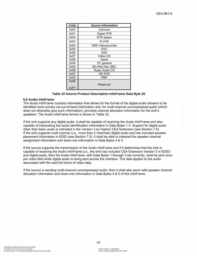
CEA-861-E
47
Code Source Information0x00 unknown 0x01 Digital STB 0x02 DVD player 0x03 D-VHS 0x04 HDD Videorecorder 0x05 DVC 0x06 DSC 0x07 Video CD 0x08 Game 0x09 PC general 0x0A Blu-Ray Disc (BD) 0x0B Super Audio CD 0x0C HD DVD 0x0D PMP 0x0E
... 0xFF
Reserved
Table 22 Source Product Description InfoFrame Data Byte 25
6.6 Audio InfoFrame The Audio InfoFrame contains information that allows for the format of the digital audio streams to be identified more quickly via out-of-band information and, for multi-channel uncompressed audio (which does not otherwise give such information), provides channel allocation information for the sink’s speakers. The Audio InfoFrame format is shown in Table 23. If the sink supports any digital audio, it shall be capable of receiving the Audio InfoFrame and also capable of interpreting the audio identification information in Data Bytes 1-3. Support for digital audio other than basic audio is indicated in the Version 3 (or higher) CEA Extension (see Section 7.5). If the sink supports multi-channel (i.e., more than 2 channels) digital audio and has included speaker placement information in EDID (see Section 7.5), it shall be able to interpret the speaker channel assignment information and down-mix information in Data Bytes 4 & 5. If the source supports the transmission of the Audio InfoFrame and if it determines that the sink is capable of receiving the Audio InfoFrame (i.e., the sink has included CEA Extension Version 3 in EDID) and digital audio, then the Audio InfoFrame, with Data Bytes 1 through 3 set correctly, shall be sent once per video field while digital audio is being sent across the interface. The data applies to the audio associated with the next full frame of video data. If the source is sending multi-channel uncompressed audio, then it shall also send valid speaker channel allocation information and down-mix information in Data Bytes 4 & 5 of this InfoFrame.
Copyright Consumer Electronics Association Provided by IHS under license with CEA Sold to:GARY LI, W0519542
Not for Resale,2008/5/29 21:49:15 GMTNo reproduction or networking permitted without license from IHS
--``````,``,`,```,``,-`-`,,`,,`,`,,`---

CEA-861-E
48
InfoFrame Type Code InfoFrame Type = 0x04
InfoFrame Version Number Version = 0x01
Length of Audio InfoFrame Length of Audio InfoFrame = 10
Data Byte 1 CT3 CT2 CT1 CT0 F13=0 CC2 CC1 CC0 Data Byte 2 F27=0 F26=0 F25=0 SF2 SF1 SF0 SS1 SS0 Data Byte 3 F37=0 F36=0 F35=0 CXT4 CXT3 CXT2 CXT1 CXT0 Data Byte 4 CA7 CA6 CA5 CA4 CA3 CA2 CA1 CA0 Data Byte 5 DM_INH LSV3 LSV2 LSV1 LSV0 F52=0 LFEPBL1 LFEPBL0 Data Byte 6 F67=0 F66=0 F65=0 F64=0 F63=0 F62=0 F61=0 F60=0 Data Byte 7 F77=0 F76=0 F75=0 F74=0 F73=0 F72=0 F71=0 F70=0 Data Byte 8 F87=0 F86=0 F85=0 F84=0 F83=0 F82=0 F81=0 F80=0 Data Byte 9 F97=0 F96=0 F95=0 F94=0 F93=0 F92=0 F91=0 F90=0
Data Byte 10 F107=0 F106=0 F105=0 F104=0 F103=0 F102=0 F101=0 F100=0
Table 23 Audio InfoFrame Format
6.6.1 Audio Identification Information The information in Data Bytes 1-3 may be useful in identifying the audio format, audio channel count, audio sampling frequency, and number of bits per audio sample. If the DTV and the source support more than “basic audio,” as defined by the physical/link specification, then this information shall be sent and shall accurately identify the stream while digital audio is being sent. If the source only supports basic audio, it is not required to send this information, but it is recommended. In most cases, it is possible to identify the audio by parsing the actual audio stream (e.g., as specified in IEC 60958-3 [13]). In cases where the audio information in the Audio InfoFrame does not agree with the actual audio stream being received, the conflicting information in the Audio InfoFrame shall be ignored.
NOTE—HDMI requires the CT, SS, and SF fields to be set to 0 (“Refer to Stream Header”) when these items are indicated elsewhere. By extension the CXT field is also required to be set to 0.
Data Byte 1 bits CT3, CT2, CT1, and CT0, when coded, define the audio format type of the audio stream. These bits may be set according to Table 24. A sink capable of receiving digital audio shall determine the audio format by parsing the audio stream header when CT=0 (CT3=0, CT2=0, CT1=0, CT0=0). Audio format types shall be defined by the CXT field in Data Byte 3 when CT=15 (CT3=1, CT2=1, CT1=1, CT0=1). Data Byte 1, bits CC2, CC1, and CC0, when coded, indicate the audio channel count carried transmitted in the audio stream. These bits may be set according to Table 24. When CC=0 (CC2=0, CC1=0, CC0=0) a sink capable of receiving digital audio over the interface shall determine the audio channel count by parsing the audio stream header. .
Copyright Consumer Electronics Association Provided by IHS under license with CEA Sold to:GARY LI, W0519542
Not for Resale,2008/5/29 21:49:15 GMTNo reproduction or networking permitted without license from IHS
--``````,``,`,```,``,-`-`,,`,,`,`,,`---

CEA-861-E
49
CT3
CT2
CT1
CT0
Audio Coding
Type
Audio Stream Encoding Standard
Audio Stream Transport Standard
CC2
CC1
CC0
Audio Channel Count
0 0 0 0 Refer to Stream Header 0 0 0 Refer to Stream Header
0 0 0 1 PCM IEC 60958-3 [13] 0 0 1 2 channels
0 0 1 0 AC-3 ATSC A/52B [12], excluding Annex E IEC 61937-3 [15] 0 1 0 3 channels
0 0 1 1 MPEG-1 ISO/IEC 11172-3
[22] Layer 1 or Layer 2
IEC 61937-4 [16] 0 1 1 4 channels
0 1 0 0 MP3 ISO/IEC 11172-3 [22] Layer 3 IEC 61937-4 [16] 1 0 0 5 channels
0 1 0 1 MPEG2 ISO/IEC 13818-3 [23] IEC 61937-4 [16] 1 0 1 6 channels
0 1 1 0 AAC LC ISO/IEC 14496-3 [24] IEC 61937-6 [18] 1 1 0 7 channels
0 1 1 1 DTS ETSI TS 102 114 [37] IEC 61937-5 [17] 1 1 1 8 channels
1 0 0 0 ATRAC IEC 61909 [14].
See also ATRAC [61]
IEC 61937-7 [19]
1 0 0 1 DSD ISO/IEC 14496-3 [24], subpart 10, See also Super Audio CD [70].
1 0 1 0 E-AC-3 ATSC A/52B [12], with Annex E IEC 61937-3 [15]
1 0 1 1 DTS-HD DVD Forum DTS-HD [28] IEC 61937-5 [17]
1 1 0 0 MLP DVD Forum MLP [27] IEC 61937-9 [21]
1 1 0 1 DST ISO/IEC 14496-3 [24] subpart 10
1 1 1 0 WMA Pro WMA Pro Decoder Specification [30] IEC 61937-8 [20]
1 1 1 1 Refer to Audio Coding Extension Type (CXT) field in Data Byte 3
Table 24 Audio InfoFrame Data Byte 1 Data Byte 2, bits SF2, SF1, and SF0, when coded, indicate the audio sampling frequency in the audio stream. These bits shall be set according to Table 25. A sink capable of receiving digital audio shall determine the audio sampling frequency by parsing the audio stream header when SF=0 (SF2=0, SF1=0, SF0=0). Data Byte 2, bits SS1 and SS0, when coded, indicate the number of bits per audio sample in the audio stream. These bits shall be set according to Table 25. A sink capable of receiving digital audio shall determine the number of bits per audio sample by parsing the audio stream header when SS=0 (SS1=0, SS0=0)
Copyright Consumer Electronics Association Provided by IHS under license with CEA Sold to:GARY LI, W0519542
Not for Resale,2008/5/29 21:49:15 GMTNo reproduction or networking permitted without license from IHS
--``````,``,`,```,``,-`-`,,`,,`,`,,`---

CEA-861-E
50
SF2 SF1 SF0 Sampling Frequency SS1 SS0 Sample Size 0 0 0 Refer to Stream Header 0 0 Refer to Stream header 0 0 1 32 kHz 0 1 16 bit 0 1 0 44.1 kHz (CD) 1 0 20 bit 0 1 1 48 kHz 1 1 24 bit 1 0 0 88.2 kHz 1 0 1 96 kHz 1 1 0 176.4 kHz 1 1 1 192 kHz
Table 25 Audio InfoFrame Data Byte 2 Data Byte 3, bits CXT4, CXT3, CXT2, CXT1, and CXT0, when coded and when the CT field in Data Byte 1 is set to 15, indicate the audio format type of the audio stream. The CXT4-CXT0 bits shall be set to 0x00 (CXT4=0, CXT3=0, CXT2=0, CXT1=0, CXT0=0) when the CT field in Data Byte 1 is set to a value other than 15. When the CT field in Data Byte 1 is set to 15 (CT3=1, CT2=1, CT1=1, CT0=1) the CXT bits may be set according to Table 26. When CXT=0 (CXT4=0, CXT3=0, CXT2=0, CXT1=0, CXT0=0) a sink capable of receiving digital audio shall determine the audio format by analyzing the value of the CT field in Data Byte 1 or by parsing the audio stream header.
CXT4
CXT3
CXT2
CXT1
CXT0
Audio Coding
Extension Type
Audio Stream Encoding Standard
Audio Stream Transport Standard
0 0 0 0 0 Refer to Audio Coding Type (CT) field in Data Byte 1 0 0 0 0 1 HE-AAC ISO/IEC 14496-3:2005 [24] IEC 61937-6 [18]
0 0 0 1 0 HE-AACv2 ISO/IEC 14496-3:2005/AMD2:2006 [25] IEC 61937-6 [18]
0 0 0 1 1 MPEG Surround ISO/IEC 23003-1:2007 [26]
0x04 – 0x1F Reserved
Table 26 Audio Format Code Extension (Data Byte 3)
6.6.2 Speaker Mapping and Down-mix Information Data Bytes 4 and 5 apply only to multi-channel (i.e., more than two channels) uncompressed audio. CEA-861-E contains the capability to transmit Multi-Channel Linear Pulse Code Modulation (LPCM) Audio by using up to four IEC 60958-3 [13] compliant transport streams. This is because the Audio InfoFrame and the CEA Extension are capable of supporting up to eight channels of LPCM. However, additional information is required to support carriage of Multi-Channel LPCM streams. This information is provided by the speaker channel allocation information in Data Byte 4. Data Byte 4 contains information that describes how various speaker locations are allocated to transmission channels. Data Byte 5 contains information that tells the sink how much the source attenuated the audio during a down-mixing operation. The down-mix inhibit flag (DM_INH) describes whether audio output is permitted to be down-mixed or not. This flag is used in DVD Audio applications. The labels and placements of speakers used in CEA-861-E are defined in Figure 6 and Table 27 (see Annex K for additional information concerning speaker placement relationships between CEA-861-E and other standards).
Copyright Consumer Electronics Association Provided by IHS under license with CEA Sold to:GARY LI, W0519542
Not for Resale,2008/5/29 21:49:15 GMTNo reproduction or networking permitted without license from IHS
--``````,``,`,```,``,-`-`,,`,,`,`,,`---

CEA-861-E
51
FL FLC FC FRC FR
RL RLC RC RRC RR
LFE FRONT
REAR
TC
FLH FCH FRH
FLW FRW
Figure 6 Speaker Placement
Label LocationFL Front Left FC Front Center FR Front Right FLC Front Left Center FRC Front Right Center RL Rear Left RC Rear Center RR Rear Right RLC Rear Left Center RRC Rear Right Center LFE Low Frequency Effect FLW Front Left Wide FRW Front Right Wide FLH Front Left High FCH Front Center High FRH Front Right High TC Top Center
Table 27 Speaker Placement NOTE—FLW/FRW are front perimeter speakers, outside of the front main speakers. FLH/FCH/FRH are front elevated speakers, generally above the front main speakers. The TC is an upper surround or overhead speaker, directly above overhead. Data Byte 4 contains information that describes how various speaker locations are allocated to transmission channels. Channel allocation is shown in Table 28 (see Annex K for additional information concerning audio channel allocation relationships between CEA-861-E and other standards).
Copyright Consumer Electronics Association Provided by IHS under license with CEA Sold to:GARY LI, W0519542
Not for Resale,2008/5/29 21:49:15 GMTNo reproduction or networking permitted without license from IHS
--``````,``,`,```,``,-`-`,,`,,`,`,,`---

CEA-861-E
52
CA (binary)
CA(hex) Channel Number
7 6 5 4 3 2 1 0 8 7 6 5 4 3 2 1 0 0 0 0 0 0 0 0 0x00 - - - - - - FR FL 0 0 0 0 0 0 0 1 0x01 - - - - - LFE FR FL 0 0 0 0 0 0 1 0 0x02 - - - - FC - FR FL 0 0 0 0 0 0 1 1 0x03 - - - - FC LFE FR FL 0 0 0 0 0 1 0 0 0x04 - - - RC - - FR FL 0 0 0 0 0 1 0 1 0x05 - - - RC - LFE FR FL 0 0 0 0 0 1 1 0 0x06 - - - RC FC - FR FL 0 0 0 0 0 1 1 1 0x07 - - - RC FC LFE FR FL 0 0 0 0 1 0 0 0 0x08 - - RR RL - - FR FL 0 0 0 0 1 0 0 1 0x09 - - RR RL - LFE FR FL 0 0 0 0 1 0 1 0 0x0A - - RR RL FC - FR FL 0 0 0 0 1 0 1 1 0x0B - - RR RL FC LFE FR FL 0 0 0 0 1 1 0 0 0x0C - RC RR RL - - FR FL 0 0 0 0 1 1 0 1 0x0D - RC RR RL - LFE FR FL 0 0 0 0 1 1 1 0 0x0E - RC RR RL FC - FR FL 0 0 0 0 1 1 1 1 0x0F - RC RR RL FC LFE FR FL 0 0 0 1 0 0 0 0 0x10 RRC RLC RR RL - - FR FL 0 0 0 1 0 0 0 1 0x11 RRC RLC RR RL - LFE FR FL 0 0 0 1 0 0 1 0 0x12 RRC RLC RR RL FC - FR FL 0 0 0 1 0 0 1 1 0x13 RRC RLC RR RL FC LFE FR FL 0 0 0 1 0 1 0 0 0x14 FRC FLC - - - - FR FL 0 0 0 1 0 1 0 1 0x15 FRC FLC - - - LFE FR FL 0 0 0 1 0 1 1 0 0x16 FRC FLC - - FC - FR FL 0 0 0 1 0 1 1 1 0x17 FRC FLC - - FC LFE FR FL 0 0 0 1 1 0 0 0 0x18 FRC FLC - RC - - FR FL 0 0 0 1 1 0 0 1 0x19 FRC FLC - RC - LFE FR FL 0 0 0 1 1 0 1 0 0x1A FRC FLC - RC FC - FR FL 0 0 0 1 1 0 1 1 0x1B FRC FLC - RC FC LFE FR FL 0 0 0 1 1 1 0 0 0x1C FRC FLC RR RL - - FR FL 0 0 0 1 1 1 0 1 0x1D FRC FLC RR RL - LFE FR FL 0 0 0 1 1 1 1 0 0x1E FRC FLC RR RL FC - FR FL 0 0 0 1 1 1 1 1 0x1F FRC FLC RR RL FC LFE FR FL 0 0 1 0 0 0 0 0 0x20 - FCH RR RL FC - FR FL 0 0 1 0 0 0 0 1 0x21 - FCH RR RL FC LFE FR FL 0 0 1 0 0 0 1 0 0x22 TC - RR RL FC - FR FL 0 0 1 0 0 0 1 1 0x23 TC - RR RL FC LFE FR FL 0 0 1 0 0 1 0 0 0x24 FRH FLH RR RL - - FR FL 0 0 1 0 0 1 0 1 0x25 FRH FLH RR RL - LFE FR FL 0 0 1 0 0 1 1 0 0x26 FRW FLW RR RL - - FR FL 0 0 1 0 0 1 1 1 0x27 FRW FLW RR RL - LFE FR FL 0 0 1 0 1 0 0 0 0x28 TC RC RR RL FC - FR FL 0 0 1 0 1 0 0 1 0x29 TC RC RR RL FC LFE FR FL 0 0 1 0 1 0 1 0 0x2A FCH RC RR RL FC - FR FL 0 0 1 0 1 0 1 1 0x2B FCH RC RR RL FC LFE FR FL 0 0 1 0 1 1 0 0 0x2C TC FCH RR RL FC - FR FL 0 0 1 0 1 1 0 1 0x2D TC FCH RR RL FC LFE FR FL
Copyright Consumer Electronics Association Provided by IHS under license with CEA Sold to:GARY LI, W0519542
Not for Resale,2008/5/29 21:49:15 GMTNo reproduction or networking permitted without license from IHS
--``````,``,`,```,``,-`-`,,`,,`,`,,`---

CEA-861-E
53
0 0 1 0 1 1 1 0 0x2E FRH FLH RR RL FC - FR FL 0 0 1 0 1 1 1 1 0x2F FRH FLH RR RL FC LFE FR FL 0 0 1 1 0 0 0 0 0x30 FRW FLW RR RL FC - FR FL 0 0 1 1 0 0 0 1 0x31 FRW FLW RR RL FC LFE FR FL
0 0 1 1 0 0 1 0 0x32
Reserved …
1 1 1 1 1 1 1 1 0xFF
Table 28 Audio InfoFrame Data Byte 4 The sink’s speaker allocation is not always the same as that contained within the source audio. In this case, the source should down mix the audio in order to properly meet the sink’s speaker configuration. In actual implementations, all down-mix coefficients are equally attenuated to prevent calculation overflows. The total sound level becomes lower after down-mixing. For this reason, the Level Shift Value should also be transmitted to the sink to insure the proper sound level is achieved. Data Byte 5 contains Level Shift Information, a Down-mix Inhibit Flag, and LFE playback level information. The values of attenuation associated with the Level Shift Values (LSV0-LSV3) are shown in Table 29.
LSV3 LSV2 LSV1 LSV0 Level Shift Value 0 0 0 0 0dB 0 0 0 1 1dB 0 0 1 0 2dB 0 0 1 1 3dB 0 1 0 0 4dB 0 1 0 1 5dB 0 1 1 0 6dB 0 1 1 1 7dB 1 0 0 0 8dB 1 0 0 1 9dB 1 0 1 0 10dB 1 0 1 1 11dB 1 1 0 0 12dB 1 1 0 1 13dB 1 1 1 0 14dB 1 1 1 1 15dB
Table 29 Audio InfoFrame Data Byte 5, Level Shift Value The Down-mix Inhibit Flag is shown in Table 30.
DM_INH Describes whether the down mixed stereo output is permitted or not. 0 Permitted or no information about any assertion of this 1 Prohibited
Table 30 Audio InfoFrame Data Byte 5, Down-mix Inhibit Flag The LFE playback level information is shown in Table 31.
Copyright Consumer Electronics Association Provided by IHS under license with CEA Sold to:GARY LI, W0519542
Not for Resale,2008/5/29 21:49:15 GMTNo reproduction or networking permitted without license from IHS
--``````,``,`,```,``,-`-`,,`,,`,`,,`---

CEA-861-E
54
LFEPBL1 LFEPBL0 Describes what value is used for LFE playback level comparing with other channel signal.
0 0 Unknown or refer to other information 0 1 0 dB playback 1 0 + 10 dB playback 1 1 Reserved
Table 31 Audio InfoFrame Data Byte 5, LFE Playback Level Information
6.7 MPEG Source InfoFrame The MPEG Source InfoFrame describes aspects of the compressed video stream that were used to produce the uncompressed video. In many cases, the compressed source is MPEG2, although this InfoFrame can be applied to any similar compressed format. Some sinks may use this information to improve the displayed picture.
NOTE— Implementation of the MPEG Source Infoframe is not recommended due to issues that have been reported and not resolved. The information contained in this section is reserved for future use and enhancement.
Transmission of this information by the source is optional. Use of this information by the sink is also optional. If the source supports the transmission of the MPEG Source InfoFrame and if it determines that the sink is capable of receiving the MS InfoFrame (i.e., the sink has included CEA Extension Version 3 in EDID), then this information should be sent once per video frame when applicable. The data applies to the next full frame of video data. The format of the MPEG Source InfoFrame is shown in Table 32.
InfoFrame Type Code InfoFrame Type = 0x05 InfoFrame Version Number Version = 0x01
Length of MPEG Source InfoFrame Length of MPEG Source InfoFrame (10)
Data Byte 1 MB#0 (MPEG Bit Rate: Hz Lower Upper) Data Byte 2 MB#1 Data Byte 3 MB#2 Data Byte 4 MB#3 ( Upper Byte ) Data Byte 5 F57=0 F56=0 F55=0 FR0 F53=0 F52=0 MF1 MF0 Data Byte 6 F67=0 F66=0 F65=0 F64=0 F63=0 F62=0 F61=0 F60=0 Data Byte 7 F77=0 F76=0 F75=0 F74=0 F73=0 F72=0 F71=0 F70=0 Data Byte 8 F87=0 F86=0 F85=0 F84=0 F83=0 F82=0 F81=0 F80=0 Data Byte 9 F97=0 F96=0 F95=0 F94=0 F93=0 F92=0 F91=0 F90=0
Data Byte 10 F107=0 F106=0 F105=0 F104=0 F103=0 F102=0 F101=0 F100=0
Table 32 MPEG Source InfoFrame format Data Bytes 1-4 give the MPEG bit rate. The MPEG Bit Rate is stored as a 32-bit number and is expressed in Hertz. MB#0 contains the least significant byte while MB#3 contains the most significant byte. If the MPEG Bit Rate is unknown or this field does not apply, then all of the bits in Data Bytes 1-4 shall be set to 0. Example: 10 Mbps 10,000,000 Hz (dec.) 0x00989680 Upper … Lower Byte
Copyright Consumer Electronics Association Provided by IHS under license with CEA Sold to:GARY LI, W0519542
Not for Resale,2008/5/29 21:49:15 GMTNo reproduction or networking permitted without license from IHS
--``````,``,`,```,``,-`-`,,`,,`,`,,`---

CEA-861-E
55
Byte 1 MB#0 0x80 Lower Byte Byte 2 MB#1 0x96 Byte 3 MB#2 0x98 Byte 4 MB#3 0x00 Upper
MF1 and MF0 in Data Byte 5 (see Table 33) designate whether the current field/frame was generated from an I, B, or P picture from the source MPEG stream. If this is unknown or does not apply, then the field shall be set to “unknown.” In some cases, the source creates 60 field/second video from 24 frames/second source material. 3:2 pulldown is commonly used. FR0 can be used to designate whether a field is a repeated field or not. The sink can use this information to improve the picture. If 3:2 pulldown does not apply to the current video decoding, then all of the fields/frames should be marked as “New field.”
FR0 Field Repeat (for 3:2 pull-down) MF1 MF0 MPEG Frame
0 New field (picture) 0 0 Unknown (No Data) 1 Repeated Field 0 1 I Picture 1 0 B Picture 1 1 P Picture
Table 33 MPEG Source InfoFrame Data Byte 5
6.8 NTSC VBI InfoFrame The NTSC VBI InfoFrame provides for the carriage of SCTE 127 [29] payloads containing VBI data. Transmission of this information by the source is optional. Use of this information by the sink is also optional. However, when present, sinks can extract this information for direct use, or when analog NTSC outputs are present, regenerate relevant VBI data along with the video and audio. This InfoFrame should be sent once per video frame when applicable. The data applies to the next full frame of video data. The format of the NTSC VBI InfoFrame is shown in Table 34.
InfoFrame Type Code InfoFrame Type = 0x06 InfoFrame Version Number Version = 0x01
Length of NTSC VBI Length of NTSC VBI InfoFrame – total number of bytes following this field
Data Bytes 1…Length The PES_data_field() structure of SCTE 127, Table 2 [29]
Table 34 NTSC VBI InfoFrame The stuffing_bytes should be omitted before source transmission. In order to maximize the possibility of operation with existing silicon, sources should constrain the InfoFrame to 31 bytes or less. This means the PES_data_field() structure would be constrained (modified if necessary) to 27 bytes. NABTS (which requires 37 bytes) should not be encoded. Note: 31 bytes is adequate, for example, for two fields of AMOL96 and one field of TVG2X per frame.
7 EDID Data Structure Extended Display Identification Data (EDID) was created by VESA to enable plug and play capabilities of displays (sinks). This data, which is stored in the sink, describes video formats that the DTV (display) is
Copyright Consumer Electronics Association Provided by IHS under license with CEA Sold to:GARY LI, W0519542
Not for Resale,2008/5/29 21:49:15 GMTNo reproduction or networking permitted without license from IHS
--``````,``,`,```,``,-`-`,,`,,`,`,,`---

CEA-861-E
56
capable of receiving and rendering. The information is supplied to the source, over the interface, upon the request of the source. The source then chooses its output format, taking into account the format of the original video stream and the formats supported by the sink. Format conversions necessary to supply video to the sink should be determined according to recommendations in Annex F. The EDID data structures version 1, revision 3 [10] and newer are known as Enhanced EDID (E-EDID). Sources should interpret and sinks should implement the EDID data structure according to the VESA E-EDID Implementation Guide [59]. Sink implementers should verify a sink’s EDID data structure using the VESA E-EDID Verification Guide [63].The sink shall support E-DDC [9] as the method of transporting EDID information. A source shall be capable of using E-DDC [9] to read the entire EDID since critical information may not otherwise be readable if the sink contains a large EDID. Some sinks may contain more than 2 blocks of EDID data. For example, the sink may include a second CEA-861 Extension Block, a VESA DI-EXT Block (as defined in VESA DI-EXT [58]) or a VTB-EXT Block (as defined in VESA VTB-EXT [66]). In this case the sink is required to support E-DDC Addressing (using the Segment Pointer) as defined in VESA E-DDC [9]. It is also recommended that the source be capable of reading and parsing more than 2 blocks of EDID data. For more information on E-DDC addressing refer to the VESA E-DDC Standard [9]. The base EDID (Block 0) contains both version and revision numbers. The version number indicates the data structure of the base EDID, which remains backwards compatible as the revision number changes. Therefore, a source should continue parsing a recognized structure version - even if it encounters an unexpected revision number. The sink shall protect its EDID from accidental corruption resulting from I2C errors by write-protecting its contents. See Annex A and Annex D for an example EDID.
7.1 Use of CEA Extensions Two of the four 18-byte descriptor slots contained in EDID Block 0 are designated for a Monitor Range Limits Descriptor and a Monitor Name Descriptor. Users of CEA-861-E should note that future alternate usage of these descriptors is possible, including replacing them with additional Detailed Timing Descriptors, and, therefore, dependency upon data in these descriptors should be avoided. Consequently, the E-EDID standard provides a method for including only two Detailed Timing Descriptors. To accommodate additional Detailed Timing Descriptors, the CEA Extension has been defined. The tag (0x02) for this extension was previously reserved within VESA, but has now been assigned to CEA for the purposes of CEA-861-E. Therefore, further changes to this structure are under the control of CEA. It is referred to in CEA-861-E as the CEA Extension. Three versions of the CEA Extension exist. If more than one CEA Extension is included in EDID, they shall all be the same version. To maintain backward compatibility, newer versions of the CEA Extension include all of the fields that were present in the previous versions. Additionally, length fields are provided on internal data structures to convey block size and to aid the source in interpreting the data. This may help a source to determine whether or not the field is valid. Future versions of the CEA Extension are expected to have the version number incremented and be backward compatible with previous versions. A current generation source is capable of parsing these future EDIDs exactly as it does existing EDIDs, if it ignores the version number. Sources should continue parsing the EDID structure even if an unexpected version number is encountered. CEA Extension Version 1 only provides a way to supply extra Detailed Timing Descriptors. It is still permitted to be used for some sinks (e.g. limited format DVI displays) but Version 3 is more applicable for most devices.
Copyright Consumer Electronics Association Provided by IHS under license with CEA Sold to:GARY LI, W0519542
Not for Resale,2008/5/29 21:49:15 GMTNo reproduction or networking permitted without license from IHS
--``````,``,`,```,``,-`-`,,`,,`,`,,`---

CEA-861-E
57
CEA Extension Version 2 is no longer supported and shall not be included in sinks. CEA Extension Version 3 includes all of the fields and capabilities of Versions 1 & 2, but also includes the ability to specify any of the CEA video formats using “CEA Short Video Descriptors.” It provides the ability for the sink to specify what types of advanced audio it supports using “CEA Short Audio Descriptors.” It also provides a way for the sink to specify its speaker configuration. This information is complementary to the speaker channel allocation information that is sent in the Audio InfoFrame. If a sink supports any video format with a format code greater than 7, YCBCR color space, InfoFrames, or digital audio (e.g., is an HDMI monitor), then it shall include the version 3 (or higher) CEA Extension in its EDID data structure.
7.2 Describing Video Formats in EDID Two methods of describing video formats are used in CEA-861-E: Detailed Timing Descriptors and CEA Short Video Descriptors. The sink shall declare support for all of the DTV formats that it supports in EDID block 0 or in the CEA Extension(s). The 640x480@60Hz flag, in the Established Timings area, shall always be set, since the 640x480p format is a mandatory default timing. When using CEA Extension Version 1, all of the CEA video formats listed in E-EDID are described using Detailed Timing Descriptors. No matter which CEA Extension is used, there is also room for two Detailed Timing Descriptors in EDID Block 0. CEA Extension Version 3 can include a combination of Detailed Timing Descriptors and Short Video Descriptors. If a Version 3 CEA Extension has been included in EDID, all CEA video formats shall be advertised using Short Video Descriptors, even if they are also advertised using the Detailed Timing Descriptors (see 7.2.1). Even though Short Video Descriptors are available in the Version 3 CEA Extension, there is still a need to use Detailed Timing Descriptors if full backward compatibility with legacy sources is desired. Formats with video ID codes of 2 to 5 and 17 to 20 should be advertised using the Detailed Timing Descriptors for any video formats that the DTV designer wishes to guarantee are available to sources that cannot interpret the Short Video Descriptors and that require Detailed Timing Descriptors for proper operation. If sufficient room is not available in the first two blocks of the EDID for all of the supported video formats, the DTV designer may choose to declare support for some of the less important formats in Short Video Descriptors only.
7.2.1 Use of EDID Detailed Timing Descriptors As required in Section 4, a DTV that declares it is capable of displaying a video timing with a vertical frequency that is either an integer multiple of 6 Hz or an integer multiple of 6 Hz adjusted by a factor of 1000/1001 shall be capable of displaying both versions of the video timing. DTVs capable of displaying 59.94/60 Hz versions of video timings shall declare in the EDID structure the 60Hz version of the video timing for all video formats, except the 240-line and 480-line formats, which shall declare 59.94Hz version of the video timing. All DTDs and SVDs shall be listed in order of priority; meaning that the first is the one that the display manufacturer has identified as optimal. Note that the EDID Detailed Timing Descriptor allows for the designation of an interlaced format. However, there are no provisions to specify separate vertical blanking/sync for Field 1 and Field 2. Therefore, for the purposes of CEA-861-E, the following rules apply for interlaced formats: a) The Field 1 Vertical Blanking Interval shall equal the Vertical Blanking Lines in the Detailed Timing
Descriptor. b) The Field 2 Vertical Blanking Interval shall equal the Vertical Blanking Lines in the Detailed Timing
Descriptor + 1.
Copyright Consumer Electronics Association Provided by IHS under license with CEA Sold to:GARY LI, W0519542
Not for Resale,2008/5/29 21:49:15 GMTNo reproduction or networking permitted without license from IHS
--``````,``,`,```,``,-`-`,,`,,`,`,,`---

CEA-861-E
58
c) The Field 1 Vertical Sync Offset shall equal the Vertical Sync Offset in the Detailed Timing Descriptor. d) The Field 2 Vertical Sync Offset shall equal the Vertical Sync Offset in the Detailed Timing Descriptor
+ 1/2. A sink capable of receiving a video format with a video identification code greater than 7 or capable of receiving a dual-aspect ratio timing shall declare different Detailed Timing Descriptors in its EDID for each supported video timing with a different picture aspect ratios. The vertical and horizontal image size parameters in the EDID shall contain numbers that describe the aspect ratio of the displayed video (actual dimensions are preferred, but not required). A special interlaced video timing exists (see Figure 5) that modifies the Field 2 Vertical Blanking Interval (b) and Vertical Sync Offset (d) values presented here. When all DTD parameters match those of video identification code 39 (see Table 35) and a SVD indicating support for code 39 video format also exists, the Field 2 Vertical Blanking Interval (b) and Vertical Sync Offset (d) shall instead equal the DTD's "Vertical Blanking Lines" and the DTD's "Vertical Sync Offset" - 1/2, respectively.
Byte #
Data Hex Dec
Description Remarks
1 0x20 32 Pixel Clock 72.00 MHz 2 0x1C 28 3 0x80 128 H Active 1920 pixels 4 0x80 128 H Blanking 384 pixels 5 0x71 113 H Active: H Blanking 6 0x1C 28 V Active 540 lines 7 0x55 85 V Blanking 85 lines 8 0x20 32 V Active: V Blanking 9 0x20 32 H Sync Offset 32 pixels 10 0xA8 168 H Sync Pulse Width 168 pixels 11 0x75 117 VS Offset: VS Pulse
Width 23 lines, 5 lines
12 0x04 4 HS Offset: HS Pulse Width: VS Offset: VS Pulse Width
13 (any) (any) H Image Size (any) 14 (any) (any) V Image Size (any) 15 (any) (any) H&V Image Size 16 0x00 0 H Border 0 lines 17 0x00 0 V Border 0 pixels 18 0x9A,
0x9B, 0xBA, 0xBB, 0xDA, 0xDB, 0xFA, or 0xFB
154, 155, 186, 187, 218, 219, 250, or 251
Flags Interlaced, digital separate, Vsync polarity is negaitve, Hsync polarity is positive (NOTE: stereo mode bits 0, 5, & 6 may have any value)
Table 35 Video Timing Code 39 Detailed Timing Descriptor Examples of Detailed Timing Descriptors for the video formats are contained in Annex A.
7.2.2 Order of Dual-Aspect Ratio Detailed Timing Descriptors A sink that supports any dual aspect ratio timing shall, in its EDID, list the DTD and SVD with the preferred picture aspect ratio before the DTD and SVD with the other picture aspect ratio. Per section 4.1,
Copyright Consumer Electronics Association Provided by IHS under license with CEA Sold to:GARY LI, W0519542
Not for Resale,2008/5/29 21:49:15 GMTNo reproduction or networking permitted without license from IHS
--``````,``,`,```,``,-`-`,,`,,`,`,,`---

CEA-861-E
59
a sink is required to assume that any video field matching a video timing is to be displayed at the preferred picture aspect ratio unless it receives an alternate indication in an AVI InfoFrame. A sink not capable of receiving AVI InfoFrames shall only declare video formats with different video timings in its EDID data structure unless the sink declares it is capable of displaying a video timing in either picture aspect ratio.
7.2.3 Source Requirements and Recommendations It is strongly recommended that a source provide an option of operating in "pass-through" mode. When operating in "pass-through" mode, the source transmits the video to the sink without performing any interlacing, deinterlacing, or scaling on the transmitted content. A source operating in "pass through" mode determines the supported video formats of the sink and utilizes this information to ensure that it passes through only video formats supported by the sink. If no corresponding video format is supported by the sink, then some conversion is necessary; it is recommended that the conversion be to the first format in the EDID that the source supports. Detailed recommendations for sources and sinks, plus examples of different conversions are illustrated in Annex F. Typically, PCs and game machines locally determine the resolution of the content rather than processing pre-recorded or broadcast content at a preset resolution. In these cases, it is recommended that the source generate the content in the first format in the EDID that the source supports. The source shall read the EDID to determine if a specific format is supported. The source shall only choose an output format listed in the EDID except in the following circumstances:
1. The source can not find a format in the EDID which it supports. 2. The user manually overrides the automatic behavior.
7.3 CEA Extension Version 1 The first version was created for CEA-861 and only provides a way to supply extra EDID Detailed Timing Descriptors. The CEA Extension in Table 36 follows the format described in Section 2.2.1.3 of VESA E-EDID Standard [10]. The EDID Extension Tag for this extension shall be 0x02. The first detailed timing (DTD) listed in the base EDID data structure is preferred. The first short video descriptor (SVD), listed in the CEA extension, is also preferred.
Copyright Consumer Electronics Association Provided by IHS under license with CEA Sold to:GARY LI, W0519542
Not for Resale,2008/5/29 21:49:15 GMTNo reproduction or networking permitted without license from IHS
--``````,``,`,```,``,-`-`,,`,,`,`,,`---

CEA-861-E
60
Byte # Value Description Format0 0x02 Tag (0x02) 1 0x01 Revision Number 2 Byte number offset d where 18-byte
descriptors begin (typically Detailed Timing Descriptors)
d = offset for the byte following the reserved data block. If no data is provided in the reserved data block, then d=4. If no DTDs are provided, then d=0.
3 Reserved Set to 0x00 4
Start reserved data block This section was previously reserved for 8 byte timing descriptors but is currently a reserved data block.
d-1 End of reserved data block.
d Start of 18-byte descriptors See Section 3.10.2 of VESA E-EDID Standard [10] d+(18*n)-1 End of 18-byte descriptors where n is
the number of descriptors included d+(18*n) 0x00 Beginning of Padding
126 0x00 End of Padding 127 Checksum 0xXX = This byte should be
programmed such that a one-byte checksum (add all bytes together) of the entire 128 byte block equals 0x00.
Table 36 CEA Extension Version 1
7.4 CEA Extension Version 2 CEA Extension Version 2 is deprecated and shall not be included in sinks. See Table 37.
Copyright Consumer Electronics Association Provided by IHS under license with CEA Sold to:GARY LI, W0519542
Not for Resale,2008/5/29 21:49:15 GMTNo reproduction or networking permitted without license from IHS
--``````,``,`,```,``,-`-`,,`,,`,`,,`---

CEA-861-E
61
Byte # Value Description Format0 0x02 Tag (0x02) 1 0x02 Revision Number 2 Byte number offset d where 18-byte
descriptors begin (typically Detailed Timing Descriptors)
d = offset for the byte following the reserved data block. If no data is provided in the reserved data block, then d=4. If d=0, then no detailed timing descriptors are provided and no data is provided in the reserved data block.
3 Total number of native Detailed Timing Descriptors in entire E-EDID structure. Also, indication of underscan support, audio support, and support of YCBCR is included
bit 7 (underscan) = 1 if sink underscans IT video formats by default. bit 6 (audio) = 1 if sink supports basic audio. bit 5 (YCBCR 4:4:4) = 1 if sink supports YCBCR 4:4:4 in addition to RGB. bit 4 (YCBCR 4:2:2) = 1 if sink supports YCBCR 4:2:2 in addition to RGB. lower 4 bits = total number of native DTDs (see Section 2.2 for definition of "Native Format").
4
Start reserved data block This section was previously reserved for 8 byte timing descriptors8 but is currently a reserved data block. d-1 End of reserved data block.
d Start of 18-byte descriptors See Section 3.10.2 of VESA E-EDID Standard[10] d+(18*n)-1 End of 18-byte descriptors where n is
the number of descriptors included d+(18*n) 0x00 Beginning of Padding
126 0x00 End of Padding 127 Checksum 0xXX = This byte should be
programmed such that a one-byte checksum (add all bytes together) of the entire 128 byte block equals 0x00.
Table 37 CEA Extension Version 2
7.5 CEA Extension Version 3 Version 3 includes all of the capabilities of Versions 1 & 2, but also includes the ability to specify any of the CE video formats using “CEA Short Video Descriptors.” It provides the ability for the sink to specify what types of advanced audio it supports using “CEA Short Audio Descriptors.” It also provides a way for the sink to specify its speaker configuration. This information is complementary to the speaker channel allocation information that is sent in the Audio InfoFrame. If more than one CEA extension is needed, the value of byte 3 shall be the same in all extensions. CEA Extension Version 3 is shown in Table 38.
8 The 8-byte descriptors do not support the CE video formats defined in this standard since they are not compliant with VESA GTF [60].
Copyright Consumer Electronics Association Provided by IHS under license with CEA Sold to:GARY LI, W0519542
Not for Resale,2008/5/29 21:49:15 GMTNo reproduction or networking permitted without license from IHS
--``````,``,`,```,``,-`-`,,`,,`,`,,`---

CEA-861-E
62
Byte # Value Description Format 0 0x02 Tag (0x02) 1 0x03 Revision Number 2 Byte number offset d where 18-byte
descriptors begin (typically Detailed Timing Descriptors)
d = offset for the byte following the reserved data block. If no data is provided in the reserved data block, then d=4. If d=0, then no detailed timing descriptors are provided and no data is provided in the reserved data block.
3 Total number of Detailed Timing Descriptors describing native formats in entire E-EDID structure. Also, indication of underscan support, audio support, and support of YCBCR is included
bit 7 (underscan) = 1 if sink underscans IT video formats by default. bit 6 (audio) = 1 if sink supports basic audio. bit 5 (YCBCR 4:4:4) = 1 if sink supports YCBCR 4:4:4 in addition to RGB. bit 4 (YCBCR 4:2:2) = 1 if sink supports YCBCR 4:2:2 in addition to RGB. lower 4 bits = total number of native DTDs (see Section 2.2 for definition of "Native Format”).
4
Start of data block collection This section is used for CEA Data Block Collection (see Table 39).
d-1 End of data block collection. d Start of 18-byte detailed timing
descriptors See Section 3.10.2 of VESA E-EDID Standard [10]
d+(18*n)-1 End of 18-byte detailed timing descriptors where n is the number of descriptors included
d+(18*n) 0x00 Beginning of Padding 126 0x00 End of Padding 127 Checksum This byte should be programmed such that a
one-byte checksum (add all bytes together) of the entire 128 byte block equals 0x00.
Table 38 CEA Extension Version 3 The lower 4 bits of byte 3 indicates the total number of DTDs defining native formats in the whole EDID (see Section 2.2 for definition of "Native Format").The placement of native DTDs shall be contiguous, starting with the first DTD in the DTD list (which starts in the base EDID block). Value zero means that this information is not provided (for backward compatibility with prior implementations), or that the display does not support reception of native format. In most cases, the native format count equals one, but a CRT-based display may indicate support for two: a native progressive and a native interlaced timing. A DTV that declares it is capable of displaying pictures formatted in either YCBCR chroma sampling format (i.e., 4:2:2 or 4:4:4) shall be capable of displaying pictures encoded in either SMPTE 170M [1] color space or ITU-R BT.709 [7] color space. DTVs capable of displaying pictures encoded in other color spaces may declare support for these color spaces in a Colorimetry Block stored in their EDID. The format of the Colorimetry Data Block is defined in Section 7.5.5. In order to ensure YCBCR interoperability between any two YCBCR-capable devices, a sink that supports either type of YCBCR pixel data (4:2:2 or 4:4:4) should support both types and therefore would set both bits 4 and 5 of byte 3.
NOTE—The HDMI specification requires this behavior. A sink that does not support YCBCR pixel data shall have both bits 4 and 5 clear. If the sink supports any type of digital audio on this interface, then it shall also support Basic Audio and shall indicate this by setting the Basic Audio bit (bit 6).
Copyright Consumer Electronics Association Provided by IHS under license with CEA Sold to:GARY LI, W0519542
Not for Resale,2008/5/29 21:49:15 GMTNo reproduction or networking permitted without license from IHS
--``````,``,`,```,``,-`-`,,`,,`,`,,`---

CEA-861-E
63
Bit 7 of byte 3 shall be set if the sink underscans IT video formats by default. The format of the “CEA Data Block Collection” shall conform to that shown in Table 39. The order of the Data Blocks is not constrained. It is also possible to have more than one of a specific type of data block if necessary to include all of the descriptors needed to describe the sink’s capabilities. The header of a Data Block consists of one byte (Table 40), with 3 bits used for the tag code to label the type of data and 5 bits used to indicate the length of the block. The list of tag codes is shown in Table 41. The length does not include the tag. The General Tag format is shown in Table 40. The first three bits are a Tag Code. This Tag Code designates the format of the bytes that follow. The last five bits are a length field that designates the number of bytes in the data block associated with the tag. The number of bytes does not include the tag. In the case of a video data block or an audio data block, the data block consists of a number of Short Video Descriptors. For other data blocks, the format may be different (e.g., Speaker Allocation Data Block). However, the length is always the number of bytes following the tag.
Byte# Bits 5-7 Bits 0-4
Video Data Block
1 Video Tag Code
length=total number of video bytes following this byte (L1)
2 CEA Short Video Descriptor 1 3 CEA Short Video Descriptor 2 ... ... 1+L1 CEA Short Video Descriptor L1
Audio Data Block
2+L1 Audio Tag Code
length=total number of audio bytes following this byte (L2)
3+L1 CEA Short Audio Descriptor 1 4+L1
5+L1 ... ...
L1+L2 CEA Short Audio Descriptor L2/3 1+L1+L2
2+L1+L2
Speaker Allocation
Data Block
3+L1+L2 Speaker Allocation Tag Code
length=total number of speaker allocation bytes following this byte (L3=3)
4+L1+L2 Speaker Allocation Data Block Payload (3 bytes) 5+L1+L2 6+L1+L2
Vendor Specific
Data Block
7+L1+L2 Vendor Specific Tag Code
length=total number of vendor specific bytes following this byte (L4)
8+L1+L2 24-bit IEEE Registration Identifier (least significant byte first) 9+L1+L2
10+L1+L2 .... .....
Vendor Specific Data Block Payload (L4-3 bytes)
Video Capability
Data Block
8+L1+L2+L4 Extended Tag Code
length=total number of bytes in this block following this byte (L5)
9+L1+L2+L4 Video Capabilities Ext. Tag Code = 00h 10+L1+L2+L4 Video Capabilities Data Byte 3 (see section 7.5.6)
Table 39 General Format of “CEA Data Block Collection”
Copyright Consumer Electronics Association Provided by IHS under license with CEA Sold to:GARY LI, W0519542
Not for Resale,2008/5/29 21:49:15 GMTNo reproduction or networking permitted without license from IHS
--``````,``,`,```,``,-`-`,,`,,`,`,,`---

CEA-861-E
64
These data structures may grow in the future and so the source shall continue to parse the known (currently specified) fields in a data block even if the length is longer than currently specified.
bitsByte# 7 6 5 4 3 2 1 0
1 Tag Code Length of following data block payload (in bytes)
Table 40 Data Block Header Byte
Codes Type of Data Block0 Reserved 1 Audio Data Block (includes one or more Short Audio
Descriptors) 2 Video Data Block (includes one or more Short Video
Descriptors) 3 Vendor Specific Data Block 4 Speaker Allocation Data Block 5 VESA DTC Data Block 6 Reserved 7 Use Extended Tag
Table 41 CEA Data Block Tag Codes If the Tag Code is 7 (Use Extended Tag) then the second byte of the data block contains the Extended Tag Code, which indicates the actual type of the data block. For backwards compatibility, the Length field in the first byte does include the second byte, which contains the Extended Tag Code. Note that data blocks with Tag Codes of 1 through 6 are limited to containing 31 useful bytes whereas those with Extended Tag Codes are limited to 30 useful bytes.
bitsByte# 7 6 5 4 3 2 1 0
2 Extended Tag Code
Table 42 Extended Tag Format (2nd Byte of Data Block)
Extended Tag Codes
Type of Data Block
0 Video Capability Data Block 1 Vendor-Specific Video Data Block 2 Reserved for VESA Video Display Device Information Data Block 3 Reserved for VESA Video Data Block 4 Reserved for HDMI Video Data Block 5 Colorimetry Data Block
6…15 Reserved for video-related blocks 16 CEA Miscellaneous Audio Fields 17 Vendor-Specific Audio Data Block 18 Reserved for HDMI Audio Data Block
19…31 Reserved for audio-related blocks 32…255 Reserved for general
Table 43 CEA Data Block Tag Codes Any data block with an Extended Tag in the 0 to 15 range indicates strictly video-related characteristics of the display. Any repeater device that re-transmits a video stream from a source to a sink without any modification of the video timing or video data or video-related InfoFrame(s) shall also pass every such data block upstream, that is, the repeater shall copy the contents of the data block(s) from the downstream sink’s EDID to the repeater’s own upstream EDID.
Copyright Consumer Electronics Association Provided by IHS under license with CEA Sold to:GARY LI, W0519542
Not for Resale,2008/5/29 21:49:15 GMTNo reproduction or networking permitted without license from IHS
--``````,``,`,```,``,-`-`,,`,,`,`,,`---

CEA-861-E
65
Any data block with an Extended Tag in the 16 to 31 range indicates strictly audio-related characteristics of the display. Any repeater device that re-transmits an audio stream from a source to a sink without any modification of the audio timing or audio data or audio-related InfoFrame(s) shall also pass every such data block upstream, that is, the repeater shall copy the contents of the data block(s) from the downstream sink’s EDID to the repeater’s own upstream EDID. Repeaters shall not copy the contents of any other data block from a downstream EDID to their own upstream EDID unless the characteristics of the sink indicated by that data block are known to be also true for the repeater device or the combination of the repeater and downstream device. This also applies to the original Vendor-Specific Data Block (Data Block Tag = 3); if the repeater does not recognize the vendor ID or does not understand the entire contents of that block, it shall not be copied into the repeater’s EDID.
7.5.1 Video Data Block When a Version 3 CEA Extension is provided in the sink’s EDID data structure, a short video descriptor shall be provided for each CEA video format supported by the sink. The format of the short video descriptor shall conform to that shown in Table 44. The lower 7-bits are an index associated with the video format supported. These indexes are the same as those used in the AVI InfoFrame and are shown in Table 4. All DTDs and SVDs shall be listed in order of priority; meaning that the first is the one that the display manufacturer has identified as optimal. The most significant bit declares whether the format is a native format of the display (native =1, not native = 0). Typically, there is a single SVD, with its native bit set. Sources should not necessarily convert video formats to a native format, but should follow recommendations for using pass-through and preferred timing (see Section 7.2.3).
bitsByte# 7 6 5 4 3 2 1 0
1 Native Video Identification Code
Table 44 Short Video Descriptor
7.5.2 Audio Data Block If audio is supported in the sink, as indicated by the basic audio support bit in the Version 3 CEA EDID Descriptor, then CEA short audio descriptors shall be used to declare which (if any) audio formats are supported in addition to basic audio. If only basic audio is supported, no Short Audio Descriptors are necessary. The Short Audio Descriptor shall conform to the formats given in Table 45 through Table 49 as a function of the Audio Format Code. Several types of audio may be supported, but each one shall be listed in its own short audio descriptor with its designated code and the associated information. The list of Audio Format Code values is given in Table 24 and Table 26. Each Short Audio Descriptor is 3-bytes long. There can be up to 31 bytes following any tag, therefore there may be up to 10 Short Audio Descriptors in the Audio Data Block. The format of the third byte is determined by the Audio Format Code contained in the first byte as shown in Table 45 through Table 49. One format code is used for uncompressed audio (i.e., Linear PCM), the others are used for compressed audio (e.g., AC-3, MPEG2, DTS, etc.). For some compressed formats, byte 3 is further defined in other format-specific documents.
Copyright Consumer Electronics Association Provided by IHS under license with CEA Sold to:GARY LI, W0519542
Not for Resale,2008/5/29 21:49:15 GMTNo reproduction or networking permitted without license from IHS
--``````,``,`,```,``,-`-`,,`,,`,`,,`---

CEA-861-E
66
bitsByte# 7 6 5 4 3 2 1 0
1 F17=0 Audio Format Code = 0001 Max Number of channels - 1 2 F27=0 192 kHz 176.4 kHz 96 kHz 88.2 kHz 48 kHz 44.1 kHz 32 kHz 3 F37=0 F36=0 F35=0 F34=0 F33=0 24 bit 20 bit 16 bit
Table 45 CEA Short Audio Descriptor for Audio Format Code = 1 (LPCM)
bitsByte# 7 6 5 4 3 2 1 0
1 F17=0 Audio Format Code Max Number of channels - 1 2 F27=0 192 kHz 176.4 kHz 96 kHz 88.2 kHz 48 kHz 44.1 kHz 32 kHz 3 Maximum bit rate divided by 8 kHz
Table 46 CEA Short Audio Descriptor for Audio Format Codes 2 to 8
bits Byte# 7 6 5 4 3 2 1 0
1 F17=0 Audio Format Code Max Number of channels - 1 2 F27=0 192 kHz 176.4 kHz 96 kHz 88.2 kHz 48 kHz 44.1 kHz 32 kHz 3 Audio Format Code dependent value.
Table 47 CEA Short Audio Descriptor for Audio Format Codes 9 to 13
bitsByte# 7 6 5 4 3 2 1 0
1 F17=0 Audio Format Code=1110 Max Number of channels - 1 2 F27=0 192 kHz 176.4 kHz 96 kHz 88.2 kHz 48 kHz 44.1 kHz 32 kHz 3 Reserved | Profile
Table 48 CEA Short Audio Descriptor for Audio Format Code 14 (WMA Pro)
bitsByte# 7 6 5 4 3 2 1 0
1 F17=0 Audio Format Code=1111 Max Number of channels - 1 2 F27=0 192 kHz 176.4 kHz 96 kHz 88.2 kHz 48 kHz 44.1 kHz 32 kHz 3 Audio Format Code Extension F32=0 F31=0 F30=0
Table 49 CEA Short Audio Descriptor for Audio Format Code 15 (extension) The Audio Format Codes used in each Short Audio Descriptor shall be as defined for CT0-CT3 in Table 24 except that the value zero shall be reserved. The Audio Format Code Extension shall be as defined for CXT0-CXT4 in Table 26. F32, F31, and F30 are future bits and shall be set to zero.
7.5.3 Speaker Allocation Data Block If the sink supports multi-channel uncompressed digital audio as indicated in the Audio Data Block, then the Speaker Allocation Data Block shall be included in the CEA Extension. It is recommended that the sink include a valid Speaker Allocation Data Block if it supports any type of digital audio (including Basic Audio), but this is not required. The payload of the Speaker Allocation Data Block is shown in Table 50. This payload is preceded by a Tag Code Byte that includes a tag equal to 4 and a length of 3 (see Table 39 and Table 41). The first byte of the Data block payload consists of eight bits and the second byte of the Data block payload consists of three bits and five reserved bits. The sink signifies that a speaker, or pair of speakers, is present by setting the bit associated with that speaker or pair of speakers to one. The speaker designations are the same as is used in the Audio InfoFrame (see Figure 6 and Table 27). The Front Left and Front Right
Copyright Consumer Electronics Association Provided by IHS under license with CEA Sold to:GARY LI, W0519542
Not for Resale,2008/5/29 21:49:15 GMTNo reproduction or networking permitted without license from IHS
--``````,``,`,```,``,-`-`,,`,,`,`,,`---

CEA-861-E
67
channels are not independent and are shown as FL/FR in the table. The Front Left Center and Front Right Center (FLC/FRC) Rear Left and Rear Right (RL/RR), Rear Left Center and Rear Right Center (RLC/RRC), Front Left Wide and Front Right Wide (FLW/FRW), and Front Left High and Front Right High (FLH/FRH) channels are also not independent.
bitsByte# 7 6 5 4 3 2 1 0
1 FLW/FRW RLC/RRC FLC/FRC RC RL/RR FC LFE FL/FR 2 F27=0 F26=0 F25=0 F24=0 F23=0 FCH TC FLH/FRH 3 F37=0 F36=0 F35=0 F34=0 F33=0 F32=0 F31=0 F30=0
Table 50 Speaker Allocation Data Block Payload
7.5.4 Vendor Specific Data Block The content of the Vendor Specific Data Block is defined in Table 39. A sink may contain one or more Vendor-Specific Data Blocks (VSDB) to indicate proprietary information that may be of interest to the vendor's own sources. The VSDB shall contain the 3 bytes of the IEEE OUI as well as any additional payload bytes needed.
NOTE—HDMI sinks use one version of the VSDB to indicate HDMI-specific characteristics of the sink. Additional VSDBs, such as those with the vendor's own IEEE OUI, may also be included in the E-EDID.
7.5.5 Colorimetry Data Block The Colorimetry Data Block indicates support of specific extended colorimetry standards and gamut-related as yet, undefined metadata. Details regarding the contents of the Colorimetry Data Block are provided in Table 51, Table 52 and Table 53. Byte 3 is allocated for Colorimetry data. The flags for bits 0 through 4 are defined for colorimetry based upon the IEC 61966-2 series of standards. The definitions of the colorimetry flags are shown in Table 52. Setting a colorimetry flag to one shall indicate that the sink is capable of displaying pictures encoded in that colorimetry.
bitsByte# 7 6 5 4 3 2 1 0
1 Tag Code (0x07) Length of following data block (in bytes) (0x03) 2 Extended Tag Code (0x05) 3 F37=0 F36=0 F35=0 AdobeRGB AdobeYCC601 sYCC601 xvYCC709 xvYCC601 4 F47=0 F46=0 F45=0 F44=0 MD3 MD2 MD1 MD0
Table 51 Colorimetry Data Block
Flag ColorimetryxvYCC601 Standard Definition Colorimetry based on IEC 61966-2-4 [5] xvYCC709 High Definition Colorimetry based on IEC 61966-2-4 [5] sYCC601 Colorimetry based on IEC 61966-2-1/Amendment 1 [35]
AdobeYCC601 Colorimetry based on IEC 61966-2-5 [33], Annex A AdobeRGB Colorimetry based on IEC 61966-2-5 [33]
Table 52 Data Byte 3 Colorimetry Support Flags Byte 4, bits 0 through 3 are listed in Table 53 and designated for future gamut-related metadata. As yet undefined, this metadata is carried in an interface-specific way.
Copyright Consumer Electronics Association Provided by IHS under license with CEA Sold to:GARY LI, W0519542
Not for Resale,2008/5/29 21:49:15 GMTNo reproduction or networking permitted without license from IHS
--``````,``,`,```,``,-`-`,,`,,`,`,,`---

CEA-861-E
68
Flag MetadataMD0 Future metadata profile MD1 Future metadata profile MD2 Future metadata profile MD3 Future metadata profile
Table 53 Data Byte 4 Colorimetry Metadata Support Flags
7.5.6 Video Capability Data Block The Video Capability Data Block (VCDB) allows a display to declare default, fixed, or InfoFrame-controlled overscan/underscan and quantization range (see Table 54). Separate overscan/underscan handling capabilities may be declared for Preferred, IT, and CE video format categories.
NOTE—The VCDB payload currently only contains a single byte in addition to the Extended Tag Code, while future versions may contain additional bytes. The source should ignore such additional bytes (when present) and continue to parse the single byte as defined in Table 54 and Table 43.
bitsByte# 7 6 5 4 3 2 1 0
1 Tag Code (0x07) Length of following data block (in bytes) (0x02) 2 Extended Tag Code (0x00) 3 QY QS S_PT1 S_PT0 S_IT1 S_IT0 S_CE1 S_CE0
Table 54 Video Capability Data Block (VCDB)
QY
Qua
ntiz
atio
n R
ange
(A
pplie
s to
YC
C o
nly)
QS
Qua
ntiz
atio
n R
ange
Se
lect
able
(App
lies
to R
GB
onl
y)
S_PT
1 S_
PT0
PT Overscan/ underscan behavior
(Applies to the preferred video format)
S_IT
1 S_
IT0
IT Overscan/ underscan behavior
(Applies to IT video
formats)
S_C
E1
S_C
E0
CE Overscan/ underscan behavior
(Applies to CE video formats)
0 No Data 0 No Data 0 0 No Data (refer
to S_CE or S_IT fields)
0 0IT video
formats not supported
0 0 CE video formats not supported
1 Selectable (via AVI YQ) 1 Selectable
(via AVI Q) 0 1 Always Overscanned 0 1 Always
Overscanned 0 1 Always Overscanned
1 0 Always
Underscanned
1 0 Always Underscanned 1 0 Always
Underscanned
1 1
Supports both over- and underscan
1 1
Supports both over- and underscan
1 1
Supports both over- and underscan
Table 55 Video Capability Descriptor Data Byte 3 Displays do not always present the entire incoming picture to the viewer. Sometimes displays overscan the incoming video format such that pixels along the periphery of the picture are masked (occluded). For example, a display may purposely mask a portion of the picture to hide distracting content (received from
Copyright Consumer Electronics Association Provided by IHS under license with CEA Sold to:GARY LI, W0519542
Not for Resale,2008/5/29 21:49:15 GMTNo reproduction or networking permitted without license from IHS
--``````,``,`,```,``,-`-`,,`,,`,`,,`---

CEA-861-E
69
a source) or the unsightly edges of a raster. In either case, what the viewer sees is either an underscanned or overscanned picture, which may either include (in the case of underscanning) the whole incoming picture or (in the case of overscanning) a somewhat occluded picture. CE application specific displays (e.g. DTVs) typically overscan all video formats, while IT application specific displays (e.g. computer displays) typically underscan all video formats. Multipurpose displays typically adapt to the incoming signal by either overscanning or underscanning depending on the type of video format received. The S_CE, S_IT, and S_PT values allow a display to formally declare its overscan/underscan options by CE, IT, and Preferred video format category (see Table 55). Each of the three S_xx fields indicate whether the display, for all video formats in that category, always overscan those video formats, always underscan those formats or support both overscanning and underscanning of those formats. Indications shall be accurate for all video format categories – so long as a VCDB is present in the EDID. If the display does not support the reception of one of the two main video format categories (CE and IT), then the indication for the unsupported category shall be set to 00. The display’s Preferred Video Format may be either a CE or an IT video format but may have different overscan/underscan behavior than the rest of the CE or IT video formats supported by the display. If the display declares a non-zero value for the S_PT (preferred timing overscan/underscan behavior) field, and the source outputs that video format, then the S_PT declaration shall take precedence over both S_CE and S_IT declarations. If the S_PT field is 0 then the overscan/underscan behavior of this format is indicated by either the S_CE or S_IT fields, depending on whether the Preferred Video Format is a CE or IT video format. If the display declares that it can support both overscan and underscan for a video format category and the source outputs that type, then the display shall either automatically overscan or underscan (in response to the AVI InfoFrame S field) or provide user options of selecting an overscan or an underscan mode. If operating in an automatic mode, the display shall overscan the incoming picture if it receives AVI S=1 and it shall underscan if it receives AVI S=2. The source shall always set the AVI S field correctly if that information is known by the source. If the display receives no AVI or AVI S=0, then the display should overscan CE video formats and underscan IT video formats by default but may provide a user-selectable alternative behavior. If the display does not provide a VCDB then the source should assume that CE video formats are overscanned by the display and that IT video format behavior is indicated by CEA Extension byte 3 bit 7 (underscan). If underscan=1 then the source should assume that IT video formats are underscanned and if underscan=0, that IT video formats are overscanned. If the source outputs a video format that can be underscanned by the display, then the source may safely place essential content at the very edge of the signaled picture and the display shall ensure that the entire signaled picture is visible. When outputting a video format that is always overscanned by the display, IT sources (which normally render interactive menus and window controls along the periphery of the transmitted picture) should confine essential content to a smaller area of the signaled picture - to ensure the viewer operability. Media-centric sources, on the other hand, which fill the signaled picture with (decompressed) broadcast or prerecorded content - precomposed for an overscanned display, should simply pass-through such content without further processing. The exact dimensions of the overscanned picture may vary and are not specified in CEA-861-E. For RGB colorimetry, CEA-861-E supports both limited (16*2^(N-8) to 235*2^(N-8)) and full (0 to 255*2^(N-8)) range data when receiving video with RGB color space. By default, RGB pixel data values should be assumed to have a limited range when receiving a CE video format and a full range when receiving an IT format (see Section 5). The QS (AVI Q support) bit of byte 3 allows a display to declare that it supports the reception of either type of quantization range for any video format, under the direction
Copyright Consumer Electronics Association Provided by IHS under license with CEA Sold to:GARY LI, W0519542
Not for Resale,2008/5/29 21:49:15 GMTNo reproduction or networking permitted without license from IHS
--``````,``,`,```,``,-`-`,,`,,`,`,,`---

CEA-861-E
70
of InfoFrame Q data (see Section 6.4 for information concerning bits Q1 and Q0). This allows a source to override the default quantization range for any video format. If the sink declares a selectable RGB Quantization Range (QS=1) then it shall expect limited range pixel values if it receives Q=1 and it shall expect full range pixel values if it receives Q=2 (see section 6.4). For other values of Q, the sink shall expect pixel values with the default range for the transmitted video format. When received content encoded in sYCC601 (IEC 61966-2-1/Amendment 1 [35]), AdobeYCC601, and AdobeRGB (IEC 61966-2-5 [33]) colorimetry, CEA-861-E supports both limited (16*2^(N-8) to 235*2^(N-8)) and full (0 to 255*2^(N-8)) quantization ranges. By default, sYCC601 and AdobeYCC601 YCC pixel data values should be assumed to have a limited range when receiving a CE video format and a full range when receiving an IT format. The QY (AVI YQ support) bit of byte 3 allows a display to declare that it supports the reception of either type of quantization range for any video format, under the direction of AVI InfoFrame YQ data (see Section 6.4 for information concerning bits YQ1 and YQ0). This allows a source to override the default quantization range for any video format. If the sink declares a selectable YCC Quantization Range (QY=1), then it shall expect limited range pixel values if it receives AVI YQ=0 and it shall expect full range pixel values if it receives AVI YQ=1 (see section 6.4). For other values of YQ, the sink shall expect pixel values with the default range for the transmitted video format.
7.5.7 Vendor-Specific Video Data Block The Vendor Specific Video Data Block (VSVDB) allows a display to declare up to 27-bytes of vendor-defined video capabilities-related data (see Table 56). A sink may contain one or more VSVDBs to indicate proprietary information that may be of interest to the vendor's own sources. The VSVDB shall contain the 3 bytes of the vendor's IEEE OUI as well as any additional payload bytes needed.
bitsByte# 7 6 5 4 3 2 1 0
1 Tag Code (0x07) Length (L) = number of bytes following this byte 2 Extended Tag Code (0x01) 3
24-bit IEEE Registration Identifier (least significant byte first) 4 5 6
through L+1
Vendor Specific Video Data Block Payload (L-4 bytes)
Table 56 Vendor-Specific Video Data Block (VSVDB)
7.5.8 Vendor-Specific Audio Data Block The Vendor Specific Audio Data Block (VSADB) allows a display to declare up to 27-bytes of vendor-defined audio capabilities-related data (see Table 57). A sink may contain one or more VSADBs to indicate proprietary information that may be of interest to the vendor's own sources. The VSADB shall contain the 3 bytes of the vendor's IEEE OUI as well as any additional payload bytes needed.
Copyright Consumer Electronics Association Provided by IHS under license with CEA Sold to:GARY LI, W0519542
Not for Resale,2008/5/29 21:49:15 GMTNo reproduction or networking permitted without license from IHS
--``````,``,`,```,``,-`-`,,`,,`,`,,`---

CEA-861-E
71
bitsByte# 7 6 5 4 3 2 1 0
1 Tag Code (0x07) Length (L) = number of bytes following this byte 2 Extended Tag Code (0x11) 3
24-bit IEEE Registration Identifier (least significant byte first) 4 5 6
through L+1
Vendor Specific Audio Data Block Payload (L-4 bytes)
Table 57 Vendor-Specific Audio Data Block (VSADB)
Copyright Consumer Electronics Association Provided by IHS under license with CEA Sold to:GARY LI, W0519542
Not for Resale,2008/5/29 21:49:15 GMTNo reproduction or networking permitted without license from IHS
--``````,``,`,```,``,-`-`,,`,,`,`,,`---

CEA-861-E
72
Annex A Baseline Example EDID and Detailed Timing Descriptors (Informative) CEA-CEB14 was originally written as a companion document for CEA-861-B. The intent of CEB14 was to provide a baseline example EDID for features and functions contained in CEA-861-B. For convenience, CEB14 was later subsumed into CEA-861-C as an informative Annex A. With the evolution of features and functions, Annex D was added to CEA-861 to convey information about conceptual EDID structures. In all cases, the example EDID contained in Annexes A, and D were not meant to illustrate all conceivable combinations for data block types or lengths. Annex A addresses issues related to the VESA Extended Display Identification Data (EDID) tables utilized within CEA-861-E. Annex A provides examples and guidance to manufacturers that utilize CEA-861-E; however included in this Annex are several normative requirements identified by the "shall" verb. Specifically, this guidance is for the implementation of EDID tables. Primarily, the motivation is to help insure interoperability between various sources and sinks. Annex A should in no way prohibit consumer device manufacturers from including additional features, and Annex A should not be interpreted as stipulating any form of upper limit to EDID features.
A.1 Background CEA-861-E follows requirements in the VESA Enhanced Extended Display Identification Data Standard (E-EDID). EDID tables exist within the sink and are used to declare its capabilities to sources. The source uses these declared capabilities to determine the appropriate signal parameters to send across the interface for consumption by the sink. Possibly, there are varied and inconsistent ways to create EDID tables and therefore, a common methodology is desirable to help insure interoperability between various sink and sources. The purpose of Annex A is to provide a consistent and understandable guideline for creating EDID tables that reside within consumer electronics products. Consequently, Annex A does not address implementations that utilize repeaters.
A.2 EDID Tables CEA-861-E requires use of the VESA EDID version 1, revision 3 data structure. Previous versions of EDID are not supported and such use is deprecated. EDID Version 1, Revision 3 requires use of certain features for Computer Displays. Despite these requirements, some features are not applicable to certain display technologies and applications. For example, the Monitor Range Limits descriptor and support of the Generalized Timing Formula apply to CRT based multi-scan systems and not flat panel or most consumer electronics equipment. For consumer electronics devices (CE devices) the application is limited to a simple declaration of the sink’s capabilities and attributes. This section provides an outline describing the various blocks that reside with the EDID structure.
A.2.1 EDID Table Construction The table construction is divided into blocks dedicated to specifying various attributes. Each block is 128 bytes in length. Block 0 is mandatory and the following blocks are called “extensions”. The extensions are limited to 254 blocks. It is possible to use the first extension as a data block or as an index (EDID Block Map Extension) that lists more than one extension. When only one extension is required, it is called Block 1 and is used for data. In cases where more than one extension is required, the first extension or Block 1 is used as an index map that lists extension locations. Additional extensions are referred to as Blocks, such as Block 2, Block 3, and so on. Each extension contains a Block Tag that declares the contents of each extension. Sources should read Block 0 (at address 0x7E), check for multiple extensions, identify each block or extension, and be able to appropriately interpret the data contained therein. Users should be knowledgeable of defined Tags contained within section 2.2.1.4 of the VESA E-EDID standard.
Copyright Consumer Electronics Association Provided by IHS under license with CEA Sold to:GARY LI, W0519542
Not for Resale,2008/5/29 21:49:15 GMTNo reproduction or networking permitted without license from IHS
--``````,``,`,```,``,-`-`,,`,,`,`,,`---

CEA-861-E
73
Sources should read all extensions and Block Tags. CEA Extension Version 1 or Version 3 specifies additional video formats as necessary. There are three possible versions of the CEA Extension and sources should read the contents of the extension even if they cannot recognize the version number. This is to insure that the Detailed Timing Descriptors are read. For CE devices, the number of extensions or blocks is dependent upon the amount of supported video formats and features. Annex A shows one extension containing four Detailed Timing Descriptors (see Section A.3).
A.2.2 Detailed Explanation of EDID Block Zero For this discussion, block zero and subsequent extension blocks are divided into smaller sections, each receiving an explanation of terminology and use. The contents in each section are a possible example of a typical CE device application. A data format protocol is required to properly utilize the various blocks. Data within the various blocks is placed in fields with varying bit lengths. These lengths range from one bit to two bytes. The data length convention is defined and shown in Table 58
Bit range Convention1 ~ 7 bits Binary, consecutive sequence 8 bits (byte) Binary, according to location 9 ~ 15 bits Binary, sequence according to field 16 bits (two bytes) Binary, LSB first Greater than two bytes: (Character string)
ASCII code, consecutive string order, ex: HDTV = 0x48, 0x44, 0x54, 0x56
Table 58 Standard Data Lengths
A.2.3 Block Zero Header Section The header is comprised of eight addresses, 0x00 through 0x07, containing a simple binary data pattern that is used to identify the EDID table. There is one byte per address for a total of eight bytes. Address locations 0x00 and 0x07 contain data values 0x00 and locations 0x01 through 0x06 contain 0xFF as data values. CEA-861-E requires this data. This header is used to determine the beginning of an EDID structure in a sink. See Table 59.
Address Hex
Example Data Hex Dec
Format Remarks
0x00 0x00 0 Binary These fixed values are REQUIRED to properly identify start of EDID table data
0x01 0xFF 255 0x02 0xFF 255 0x03 0xFF 255 0x04 0xFF 255 0x05 0xFF 255 0x06 0xFF 255 0x07 0x00 0
Table 59 Block Zero Header Although future versions of EDID may not contain an 8-byte header at the beginning of Block 0, compliant devices are expected to use this header. However, presence of the header is not an indication that the following EDID data is valid. A checksum byte is provided for the purpose of verifying that a device’s EDID structure has been correctly read. See Section A.2.11 for more detail.
A.2.4 Vendor / Product Identification This section’s example starts and ends with address locations 0x08 and 0x11. Byte allocation for each location is as follows:
Copyright Consumer Electronics Association Provided by IHS under license with CEA Sold to:GARY LI, W0519542
Not for Resale,2008/5/29 21:49:15 GMTNo reproduction or networking permitted without license from IHS
--``````,``,`,```,``,-`-`,,`,,`,`,,`---

CEA-861-E
74
0x08 ~ 0x09 are a two byte EISA ID for Manufacturer Name and should contain a valid identification number. Data for these bytes is based upon compressed ASCII, for example: “CEA” is created by using five-bit codes, where “C” = 00011. “E” = 00101, and “A” = 00001. Table 3 illustrates the address location and sample data for Manufacturer’s Name, which is “CEA”. For information on how to obtain an EISA ID, see Microsoft Plug and Play ID - PNPID Request [69]. 0x0A ~ 0x0B are two bytes available for Product code; the manufacturer determines this code. 0x0C ~ 0x0F are four bytes to be used for product Serial Number, which is defined as a 32-bit serial number. There is no specific requirement defined for the data or format of the serial number. This field should be zero if the serial number is contained in an ASCII serial number descriptor (see Section A.2.17). CEA-861-E implementations should use 0x00 as padding for the Block 0 serial number if no serial number is provided in Block 0. For the source, if an ASCII Serial Number Descriptor is included in the sink, then the source should ignore the Serial Number field in Block 0. If no ASCII Serial Number Descriptor is present, then the field may have meaning. Ignore this block if all bytes are 0x00. 0x10 is one byte for Week of Manufacture. The designated values for this field range from 1 to 53. Values greater than 53 are not recognized. Zero may be used when no week is designated. The manufacturer determines the week numbering system. Manufacturers should use a system in which the week number’s integer value increases as the year progresses. If a manufacturer chooses to declare only the Model Year (in the field "Year of Manufacture"), then 0xFF shall be placed in Address 10 (Week of Manufacture). 0x11 is one byte representing Year of Manufacture. This value is determined by the actual year of production minus 1990. For example: 2002 – 1990 = 12 or 0x0C. See Table 60.
Copyright Consumer Electronics Association Provided by IHS under license with CEA Sold to:GARY LI, W0519542
Not for Resale,2008/5/29 21:49:15 GMTNo reproduction or networking permitted without license from IHS
--``````,``,`,```,``,-`-`,,`,,`,`,,`---

CEA-861-E
75
Address Hex
Example Data Hex Dec
Description
Remarks
0x08 0x0C 12 Manufacturer Name
using EISA ID Example = CEA 0x09 0xA1 161
0x0A 0x12 18 Product Code Used to differentiate between different models from the same manufacturer. In this example Product Code=0x3412
0x0B 0x34 52
0x0C 0x56 86 Serial Number Optional. The serial number can also be stored in a separate descriptor block (see Section A.2.17). In this example, the Serial Number=0xBC9A7856.
0x0D 0x78 120 0x0E 0x9A 154 0x0F 0xBC 188
0x10 0x10 16 Week of Manufacture If this field is unused, the value should be set to 0. If the next field is used for Model Year, then 0xFF should be set. In this example Manufacture Week=16
0x11 0x0C 12 Year of Manufacture/Model Year
Example = Manufactured Year=2002
Table 60 Vendor / Product Identification; Showing Manufacturer Week and year
A.2.5 EDID Version The version of EDID is declared in addresses 0x12 and 0x13. Each address contains one byte of data. The first address contains the version number and the second, the revision number. In the case of EDID version 1, revision 3, the value one (0x01) is placed in the first location (i.e., 0x12) and three (0x03) placed in the second area (0x13). No other numbers are allowed for this space. If other numbers are placed in this area, the source may disregard the whole EDID table. See Table 61.
Address Hex
Example Data Hex Dec
Format Remarks
0x12 0x01 1 Binary Version # 0x13 0x03 3 Revision #
Table 61 Vendor / Product Identification
A.2.6 Basic Display Parameters and Features Basic Display Parameters and Features are defined as Video Input Definition, Maximum Horizontal Image Size, Maximum Vertical Image Size, Display Transfer Characteristic (Gamma), and Feature Support. In the following example, each item is allocated one byte and the address range is from 0x14 to 0x18. 0x14: Video Input Definition is located at 0x14 and used to identify the output configuration required by the sink. For digital displays, including CE devices, the recommended setting is 0x80. This value is used to declare that the device supports a digital interface. 0x15 ~ 0x16: The Maximum Horizontal Image Size and Vertical Image Size fields (bytes 0x15, 0x16) are used to indicate the sink’s screen size and aspect ratio. When known, the maximum physical dimensions of the effective display area should be provided (in these fields, in cm). An important use of these fields is to indicate the aspect ratio of the actual screen. If the aspect ratio of the maximum image size is known, the ratio of the Maximum Size fields should equal that aspect ratio, even if the maximum image size is unknown or variable across different device configurations (such as in a projection system).
Copyright Consumer Electronics Association Provided by IHS under license with CEA Sold to:GARY LI, W0519542
Not for Resale,2008/5/29 21:49:15 GMTNo reproduction or networking permitted without license from IHS
--``````,``,`,```,``,-`-`,,`,,`,`,,`---

CEA-861-E
76
The following rules should be used in filling out the Maximum Image Size fields: a) If the aspect ratio is known and the display size is known, then the actual size should be indicated, to
the nearest cm. b) If the aspect ratio is known but the size is unknown, any values corresponding to a typical or
expected configuration of the display can be used, but the ratio of the Max Horizontal and Vertical fields shall be equal to the aspect ratio.
c) If the aspect ratio is unknown, or it is desired that it not be discoverable, then values of 0, 0 should be used.
If the fields are set to zero, the source should not make any assumptions regarding screen size or aspect ratio. In typical configurations, the image sizes described in each DTD (in bytes at offsets 0x0C, 0x0D, 0x0E, in mm) should correlate to the values in the Maximum Size fields. For instance, a 160 cm by 90 cm display would indicate 1600 mm x 900 mm for all 16:9 video formats and 1200 mm x 900 mm for all 4:3 formats. For example, data entry into the 0x15, 0x16 EDID bytes may be as summarized in Table 62. Category of Display EDID Physical
Horizontal Screen Size (cm)
EDID Physical VerticalScreen Size (cm)
Physical AR to be calculated by the source (unitless)
Direct View Enter dimension in cm Enter dimension in cm Source Divides H by V Rear Projector Enter dimension in cm Enter dimension in cm Source Divides H by V
Front Projector (enter either data row at option of implementer)
Typical dimension in cm Typical dimension in cm Source Divides H by V
Enter 0x00 Enter 0x00 AR is undefined
Table 62 Example 0x15, 0x16 EDID Screen Size Data and Certain Display Categories 0x17: Display Transfer Characteristics (Gamma) could be used by the source to tailor the video output according the display device’s gamma. The concept of declaring gamma has to do with personal computer CRT displays that accept non-gamma corrected signals. Digital and analog television video signals are gamma corrected according to established industry practices and thus the need to declare CRT gamma is not always necessary. However, this is needed for Personal Computer CRT applications. Although the source possibly may not need to use the display’s gamma value, the correct gamma value of the display device should be present. Since some television CRTs commonly have similar gamma, the value 2.2 is used in this example. The gamma value, itself, is not inserted into the table. Instead, a value equal to (gamma x 100) – 100 is inserted. 0x18: Feature Support consists of 8 bits that identify various display or sink parameters. These include power savings modes based upon VESA Display Power Management Signaling Standard (DPMS), Display Type, Standard Default Color Space, Preferred Timing Mode, and Default Generalized Timing Formula (GTF). In most cases, none of this information is relevant to CE devices and personal computer displays, since GTF is not commonly used. In Table 63, the function of each bit is indicated.
Copyright Consumer Electronics Association Provided by IHS under license with CEA Sold to:GARY LI, W0519542
Not for Resale,2008/5/29 21:49:15 GMTNo reproduction or networking permitted without license from IHS
--``````,``,`,```,``,-`-`,,`,,`,`,,`---

CEA-861-E
77
Bits Feature Description7 Standby 1 = Standby supported,
0 = not supported 6 Suspend 1 = Suspend supported,
0 = not supported 5 Active Off 1 = Active Off supported,
0 = not supported 4 ~ 3 Display Type (4:3) Bit 4 Bit 3
1 1 Undefined 1 0 Non-RGB Display 0 1 RGB Display 0 0 Monochrome Display
2 Color Space 1 = sRGB supported, 0 = not supported
1 Preferred Timing 1 = preferred timing is indicated in first detailed timing block (required), 0 = not indicated (not allowed)
0 Default GTF 1 = GTF supported, 0 = not supported
Table 63 Feature Support Detail The minimum that a CE device should declare is Display Type and Preferred Timing. In this example, 0x0A is used to designate a RGB display type and a preferred timing descriptor. The preferred timing descriptor bit shall be set to one and address locations 0x36 through 0x47 shall contain the Preferred Format. No other data is allowed in those locations. All DTDs and SVDs shall be listed in order of priority; meaning that the first is the one that the display manufacturer has identified as optimal; however, in the context of total system optimization, source implementers are advised to follow guidance provided in Section 7.2.3.
Copyright Consumer Electronics Association Provided by IHS under license with CEA Sold to:GARY LI, W0519542
Not for Resale,2008/5/29 21:49:15 GMTNo reproduction or networking permitted without license from IHS
--``````,``,`,```,``,-`-`,,`,,`,`,,`---

CEA-861-E
78
Address Hex
Example Data Hex Dec
Description Remarks
0x14 0x80 128 Video Input Definition Example indicates: Digital; VESA DFP1X: not compatible
0x15 0x50 80 Max. Horizontal Image Size in cm
CRT devices should list parameters. However, due to projector and auto sizing devices, the system should not make any assumption regarding display size if data not supplied. This example indicates a 16:9 aspect ratio device.
0x16 0x2D 45 Max. Vertical Image Size in cm
Optional; See above; This example indicates a 16:9 aspect ratio device.
0x17 0x78 120 Gamma: (gamma x 100)-100 = value
Example is: (for gamma = 2.2) (2.2 x 100)-100 = 120
0x18 0x0A 10 Feature Support Example indicates: RGB color Display type; Preferred timing: first detailed timing block; GTF timing: not supported; Standby mode: not supported; Suspend mode: not supported; Active off: not supported
Table 64 Basic Display Parameters and Features Block
A.2.7 Color Characteristics Color Characteristics provides information about the display device’s chromaticity and color temperature parameters (white temperature in degrees Kelvin). Table 66 shows EDID addresses 0x19 through 0x22, which contain data used to describe various chromaticity characteristics; this example uses 9300° K as the white color temperature. These characteristics are represented by 10-bit binary fractions. Bits nine through two of a particular characteristic are stored as a single byte in addresses 0x1B ~ 0x22. Bits one to zero of that corresponding characteristic are paired with the lower order bits of other color characteristics to form bytes and are stored in addresses 0x19 ~ 0x1A. Table 66 shows the arrangement of these fractional binary values by EDID address. In the E-EDID standard, a decimal fraction such as 0.625 is represented by a 10-bit binary value. Each of the bit positions from left to right in the binary value represent powers of 2 from 2-1 ~ 2-10. Table 65 illustrates an example decimal to binary conversion used for these color characteristics. Further explanation can be found in VESA E-EDID [10] Section 3.7.
Value 10-bit Binary Conversion0.625 1010000000 0.625 0.340 0101011100 0.33984375 0.155 0010011111 0.1552734375
Table 65 Binary to Decimal Conversion Example How the table is filled is dependent upon the setting of address 0x18 in the Feature Support section. If sRGB is selected, then all values should be set in accordance to sRGB definition. For displays not supporting the sRGB definition, the example in Table 66 is applicable.
Copyright Consumer Electronics Association Provided by IHS under license with CEA Sold to:GARY LI, W0519542
Not for Resale,2008/5/29 21:49:15 GMTNo reproduction or networking permitted without license from IHS
--``````,``,`,```,``,-`-`,,`,,`,`,,`---

CEA-861-E
79
Address Hex
Example Data Hex Dec
Description Remarks
0x19 0x0D 13 Red/Green Low Bits Bits 1~0 of RxRyGxGy = 00001101
0x1A 0xC9 201 Blue/White Low Bits Bits 1~0 of BxByWxWy = 11001001
0x1B 0xA0 160 Red-x Bits 9~2 of 10-bit value 0.625 = 10100000
0x1C 0x57 87 Red-y Bits 9~2 of 10-bit value 0.340 = 01010111
0x1D 0x47 71 Green-x Bits 9~2 of 10-bit value 0.280 = 01000111
0x1E 0x98 152 Green-y Bits 9~2 of 10-bit value 0.595 = 10011000
0x1F 0x27 39 Blue-x Bits 9~2 of 10-bit value 0.155 = 00100111
0x20 0x12 18 Blue-y Bits 9~2 of 10-bit value 0.070 = 00010010
0x21 0x48 72 White-x Bits 9~2 of 10-bit value 0.283 = 01001000
0x22 0x4C 76 White-y Bits 9~2 of 10-bit value 0.298 = 01001100
Note—This data based on a CRT Display with a white point of ~9300o K (X = 0.283; Y = 0.298)
Table 66 Color Characteristics Block Multiple white points can be specified using the Color Point Monitor Descriptor. However, there is no way to correlate to the individual video formats. Therefore chromaticity specified in Block 0 should be associated with the display device’s characteristics; however the White Point data does not. The source should not rely on the colorimetry information contained in this part of the EDID data structure for CEA-861-E formats. This recommended practice suggests the source use the colorimetry that has been associated with the format in CEA-861-E when possible. Note that this may not be possible because the source probably just passes on the video stream.
A.2.8 Established Timings In the example in Table 67, addresses 0x23 through 0x25 are used to declare Established Timings. Established Timings are computer display timings recognized by VESA. This table is also used to indicate that the established timings were adjusted and verified at the factory, which means these timings are supported and correctly rendered on the display. In the example, Table 67, address 0x23 contains the default 640x480p timing and the remaining addresses are not used to list any other timings. Personal Computers, DVI-1.0 [4], Open LDI [8], CEA-861-E require 640x480p as a default timing format. This is to insure that all source and sinks commonly support one format. Other supported or preferred timings may be described in the Standard Timing (see A.2.9) or Detailed Timing Descriptors (see A.2.10). Use of other timings is permissible. See VESA E-EDID Section 3.8.1 [10] for a list of possible formats.
Address Hex
Example Data Hex Dec
Description Remarks
0x23 0x20 32 Established Timing 1 640x480 @ 60Hz 0x24 0x00 0 Established Timing 2 None 0x25 0x00 0 Manufacturer's Timing None
Table 67 Established Timings Block
Copyright Consumer Electronics Association Provided by IHS under license with CEA Sold to:GARY LI, W0519542
Not for Resale,2008/5/29 21:49:15 GMTNo reproduction or networking permitted without license from IHS
--``````,``,`,```,``,-`-`,,`,,`,`,,`---

CEA-861-E
80
A.2.9 Standard Timing ID #1 – 8 Standard timings are those either recognized by VESA through the VESA Discrete Monitor Timing or Generalized Timing Formula standards. The display device should list timings supported. The address range for this portion of the example EDID table is 0x26 through 0x35 and the data length is two bytes. Since CE devices possibly may not support, other than the required 640x480p format, any of the VESA timings or GTF, the example in Table 68 does not contain any timing information. When no timings are declared, it is necessary to fill each unused byte, of the byte pairs, with 0x01 as padding. Other padding values are not recognized.
Address Hex
Example Data Hex Dec
Description Remarks
0x26 0x01 1 Standard Timing ID #1 PC Application 0x27 0x01 1 0x28 0x01 1 Standard Timing ID #2 PC Application 0x29 0x01 1 0x2A 0x01 1 Standard Timing ID #3 PC Application 0x2B 0x01 1 0x2C 0x01 1 Standard Timing ID #4 PC Application 0x2D 0x01 1 0x2E 0x01 1 Standard Timing ID #5 PC Application 0x2F 0x01 1 0x30 0x01 1 Standard Timing ID #6 PC Application 0x31 0x01 1 0x32 0x01 1 Standard Timing ID #7 PC Application 0x33 0x01 1 0x34 0x01 1 Standard Timing ID #8 PC Application 0x35 0x01 1
Table 68 Standard Timing ID Block
A.2.10 Detailed Timing Descriptor Block The detailed timing section is 72 bytes in length and can be divided into four descriptor blocks, which are each 18 bytes. In the following example, the address ranges for these four blocks are 0x36-0x47, 0x48-0x59, 0x5A-0x6B and 0x6C-0x7D. Each of these descriptors contains either detailed timing data (Detailed Timing Descriptor) or other specific types of data as described in the VESA E-EDID standard. The VESA E-EDID standard allows various descriptor sequences, combinations, or repetitions and sources should handle descriptors that may appear in any order. The only prescribed constraint is that Detailed Timing Descriptors precede the two required Monitor Descriptors in Block 0. The descriptors require the presence of valid data and no fill patterns are permitted in Block 0. Therefore, the source should handle these possibilities and requirements accordingly. Blocks used for data, not detailed timing information, have a five byte identifier header that is formatted as follows: 0x00, 0x00, 0x00, <Tag #>, 0x00. For more detail regarding 18-byte descriptor tags, please refer to the VESA EDID standard section 3.10.3 [10]. The example in this document configures the four blocks in this order: First Detailed Timing Descriptor, Second Detailed Timing Descriptor, First Monitor Descriptor (Monitor Name), and Second Monitor Descriptor (Monitor Range).
A.2.10.1 First Detailed Timing Descriptor The VESA E-EDID Standard [10] requires that the First Detailed Timing Descriptor be used for the most “preferred” video format and subsequent detailed timing descriptors are listed in order of decreasing preference.
Copyright Consumer Electronics Association Provided by IHS under license with CEA Sold to:GARY LI, W0519542
Not for Resale,2008/5/29 21:49:15 GMTNo reproduction or networking permitted without license from IHS
--``````,``,`,```,``,-`-`,,`,,`,`,,`---

CEA-861-E
81
Data locations within the Detailed Timing Descriptors are used to specify the video timing characteristics, image size, and contain flags for identifying interlace/non-interlace formats and sync signal polarities. Designers of source and sink need to carefully consider these types of data in all implementations. The example in Table 69 shows the data format for a Preferred Video Format of 1920x1080i and the image size is matched to the screen size of approximately 36 inches diagonal. CEA-861-E recommends listing exact horizontal and vertical dimensions, but at least requires values that describe the aspect ratio. The source should be capable of using these dimensions to determine aspect ratio. However, some EDID implementations that do not provide horizontal and vertical dimensions for non-CEA-861-E video formats may be encountered. The flags are set to convey an interlaced format and the syncs as separate and of positive polarity.
Address Hex
Example Data Hex Dec
Description Remarks(Refer to note below for additional details)
0x36 0x01 1 Pixel Clock 74.25 MHz 0x37 0x1D 29 0x38 0x80 128 H Active 1920 pixels 0x39 0x18 24 H Blanking 280 pixels 0x3A 0x71 113 H Active: H Blanking 0x3B 0x1C 28 V Active 540 lines 0x3C 0x16 22 V Blanking 22 lines 0x3D 0x20 32 V Active: V Blanking 0x3E 0x58 88 H Sync Offset 88 pixels 0x3F 0x2C 44 H Sync Pulse Width 44 pixels 0x40 0x25 37 VS Offset: VS Pulse
Width 2 lines, 5 lines
0x41 0x00 0 HS Offset: HS Pulse Width: VS Offset: VS Pulse Width
0x42 0x20 32 H Image Size 800 mm (lower 8 bits) 0x43 0xC2 194 V Image Size 450 mm (lower 8 bits) 0x44 0x31 49 H&V Image Size Upper 4 bits of H Size;
Upper 4 bits of V Size 0x45 0x00 0 H Border 0 lines 0x46 0x00 0 V Border 0 pixels 0x47 0x9E 158 Flags Interlaced, normal display no stereo, digital
separate, Vsync polarity is positive, Hsync polarity is positive
NOTE—Some addresses above contain “composite” bytes representing high and/or low order bits or “nibbles” (4 bits of an 8-bit byte). Please refer to section 3.10.2 of the VESA E-EDID standard for details on these fields.
Table 69 First Detailed Timing Descriptor Block (1920x1080i Example)
A.2.10.2 Second Detailed Timing Descriptor Table 70 contains an example for the second preferred timing using the Second Detailed Timing Descriptor block. This is the EDTV 720x480p format that has a 4:3 aspect ratio.
Copyright Consumer Electronics Association Provided by IHS under license with CEA Sold to:GARY LI, W0519542
Not for Resale,2008/5/29 21:49:15 GMTNo reproduction or networking permitted without license from IHS
--``````,``,`,```,``,-`-`,,`,,`,`,,`---

CEA-861-E
82
Address Hex
Example Data Hex Dec
Description Remarks(Refer to note below for additional details)
0x48 0x8C 140 Pixel Clock 27 MHz 0x49 0x0A 10 0x4A 0xD0 208 H Active 720 pixels 0x4B 0x8A 138 H Blanking 138 pixels 0x4C 0x20 32 H Active: H Blanking 0x4D 0xE0 224 V Active 480 lines 0x4E 0x2D 45 V Blanking 45 lines 0x4F 0x10 16 V Active: V Blanking 0x50 0x10 16 H Sync Offset 16 pixels 0x51 0x3E 62 H Sync Pulse Width 62 pixels 0x52 0x96 150 VS Offset: VS Pulse
Width 9 lines, 6 lines
0x53 0x00 0 HS Offset: HS Pulse Width: VS Offset: VS Pulse Width
0x54 0x58 88 H Image Size 600 mm (lower 8 bits) 0x55 0xC2 194 V Image Size 450 mm (lower 8 bits) 0x56 0x21 33 H&V Image Size Upper 4 bits of H Size;
Upper 4 bits of V Size 0x57 0x00 0 H Border 0 lines 0x58 0x00 0 V Border 0 pixels 0x59 0x18 24 Flags Non-interlaced, normal display no stereo, digital
separate, V. and H. sync polarity is negative NOTE—Some addresses above contain ‘composite’ bytes representing high and/or low order bits or “nibbles” (4 bits of an 8-bit byte). Please refer to section 3.10.2 of the VESA E-EDID standard for details on these fields.
Table 70 Second Detailed Timing Descriptor Block (720x480p, 4:3 Example)
A.2.10.3 First Monitor Descriptor (Monitor Name) The VESA Standard [10] requires that one of the four 18-byte descriptors be a Monitor Name Descriptor. Here, it is recommended that the third 18-byte descriptor be used as the First Monitor Descriptor or Monitor Name. Examples of these bytes are located at addresses 0x5F through 0x6B. Each location is one byte in length and is used for ASCII character string. In the example contained in Table 71, a fictitious Monitor Name is listed.
Copyright Consumer Electronics Association Provided by IHS under license with CEA Sold to:GARY LI, W0519542
Not for Resale,2008/5/29 21:49:15 GMTNo reproduction or networking permitted without license from IHS
--``````,``,`,```,``,-`-`,,`,,`,`,,`---
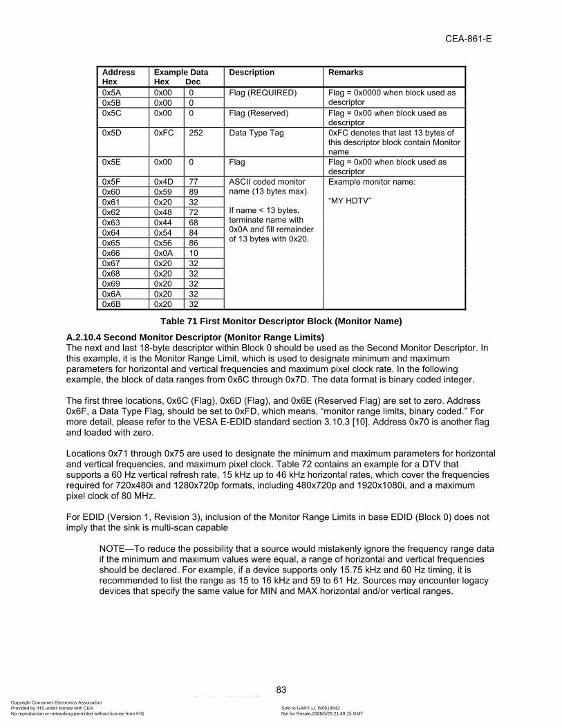
CEA-861-E
83
Address Hex
Example Data Hex Dec
Description Remarks
0x5A 0x00 0 Flag (REQUIRED) Flag = 0x0000 when block used as descriptor 0x5B 0x00 0
0x5C 0x00 0 Flag (Reserved) Flag = 0x00 when block used as descriptor
0x5D 0xFC 252 Data Type Tag 0xFC denotes that last 13 bytes of this descriptor block contain Monitor name
0x5E 0x00 0 Flag Flag = 0x00 when block used as descriptor
0x5F 0x4D 77 ASCII coded monitor name (13 bytes max). If name < 13 bytes, terminate name with 0x0A and fill remainder of 13 bytes with 0x20.
Example monitor name: “MY HDTV”
0x60 0x59 89 0x61 0x20 32 0x62 0x48 72 0x63 0x44 68 0x64 0x54 84 0x65 0x56 86 0x66 0x0A 10 0x67 0x20 32 0x68 0x20 32 0x69 0x20 32 0x6A 0x20 32 0x6B 0x20 32
Table 71 First Monitor Descriptor Block (Monitor Name)
A.2.10.4 Second Monitor Descriptor (Monitor Range Limits) The next and last 18-byte descriptor within Block 0 should be used as the Second Monitor Descriptor. In this example, it is the Monitor Range Limit, which is used to designate minimum and maximum parameters for horizontal and vertical frequencies and maximum pixel clock rate. In the following example, the block of data ranges from 0x6C through 0x7D. The data format is binary coded integer. The first three locations, 0x6C (Flag), 0x6D (Flag), and 0x6E (Reserved Flag) are set to zero. Address 0x6F, a Data Type Flag, should be set to 0xFD, which means, “monitor range limits, binary coded.” For more detail, please refer to the VESA E-EDID standard section 3.10.3 [10]. Address 0x70 is another flag and loaded with zero. Locations 0x71 through 0x75 are used to designate the minimum and maximum parameters for horizontal and vertical frequencies, and maximum pixel clock. Table 72 contains an example for a DTV that supports a 60 Hz vertical refresh rate, 15 kHz up to 46 kHz horizontal rates, which cover the frequencies required for 720x480i and 1280x720p formats, including 480x720p and 1920x1080i, and a maximum pixel clock of 80 MHz. For EDID (Version 1, Revision 3), inclusion of the Monitor Range Limits in base EDID (Block 0) does not imply that the sink is multi-scan capable
NOTE—To reduce the possibility that a source would mistakenly ignore the frequency range data if the minimum and maximum values were equal, a range of horizontal and vertical frequencies should be declared. For example, if a device supports only 15.75 kHz and 60 Hz timing, it is recommended to list the range as 15 to 16 kHz and 59 to 61 Hz. Sources may encounter legacy devices that specify the same value for MIN and MAX horizontal and/or vertical ranges.
Copyright Consumer Electronics Association Provided by IHS under license with CEA Sold to:GARY LI, W0519542
Not for Resale,2008/5/29 21:49:15 GMTNo reproduction or networking permitted without license from IHS
--``````,``,`,```,``,-`-`,,`,,`,`,,`---

CEA-861-E
84
Address Hex
Example Data Hex Dec
Description Remarks
0x6C 0x00 0 Flag Flag = 0x0000 when block used as descriptor 0x6D 0x00 0
0x6E 0x00 0 Flag (Reserved) Flag = 0x00 when block used as descriptor
0x6F 0xFD 253 Data Type Tag FDh denotes that last 13 bytes of this descriptor block contain Monitor Range limits, binary coded
0x70 0x00 0 Flag Flag = 0x00 when block used as descriptor
0x71 0x3B 59 Min Vertical Rate in Hz 59 HZ 0x72 0x3D 61 Max Vertical Rate in Hz 61 Hz 0x73 0x0F 15 Min Horizontal Rate in kHz 15 kHz 0x74 0x2E 46 Max Horizontal Rate in kHz 46 kHz 0x75 0x08 8 Max Supported pixel clock rate
in MHz/10 80 MHz
0x76 0x00 0 Tag for secondary timing formula (0x00=not used)
No secondary timing formula supported
0x77 0x0A 10 Put 0x0A after last data byte in block and fill remaining bytes with 0x20.
Unused data address 0x78 0x20 32 0x79 0x20 32 0x7A 0x20 32 0x7B 0x20 32 0x7C 0x20 32 0x7D 0x20 32
Table 72 Second Monitor Descriptor Block (Monitor Range Limits) Address 0x76 is used as a tag for a secondary generalized timing formula (GTF) and is not typically used for CE devices. In this case, the flag is set to zero. Addresses 0x77 through 0x7D are related to this tag. The E-EDID standard requires that address 0x77 contain 0x0A and addresses 0x78 ~ 0x7D contain 0x20 when no secondary GTF data is provided.
A.2.11 Extension Flag and Checksum The Extension Flag and Checksum are defined as two-byte data located in address range 0x7E through 0x7F. The Extension Flag is used to indicate that additional blocks are present in the EDID that declare additional video formats and other monitor features. The Extension Flag is used to declare the number of extensions that exist within the EDID tables. The total number of extensions actually present should equal the number of extensions declared within the base EDID. The number of extensions declared in the base EDID shall not include the base EDID, but shall include the block map. For example, if no extensions exist in the EDID data, then the Extension Flag shall be set to zero. If a single (e.g. CEA) extension is present, then the flag shall be set to one. If two (e.g. CEA) extensions are used, then a block map extension is also required by VESA EDID standard—increasing the total number of extensions to three. In this case, the extension flag is set to 3 and the sink has an EDID containing a total of four 128-byte blocks: a base block plus three extensions—the first extension being a block map.
NOTE—Some devices have been incorrectly designed so that the block map is not counted in the extension count. Design of compliant devices should take compatibility with those non-compliant devices into consideration. For example, when a source finds an extension count of 2, it may attempt to read 3 extensions on the chance that the sink has incorrectly set its count, or it may use the information in the block map as a more accurate guide.
The Checksum is set so that the sum of the entire 128-byte block modulus 256 equals 0x00. Sink designers should calculate checksum using the following formula:
Copyright Consumer Electronics Association Provided by IHS under license with CEA Sold to:GARY LI, W0519542
Not for Resale,2008/5/29 21:49:15 GMTNo reproduction or networking permitted without license from IHS
--``````,``,`,```,``,-`-`,,`,,`,`,,`---

CEA-861-E
85
Checksum byte = (256-(S%256)) %256
Where:
S is the sum of the first 127 bytes % is modulus operator
Table 73 contains example data based upon the tables presented in this document. The Extension Flag at location 0x7E is set to one declaring that Block 1 is present. Since the Extension Flag equals 1 in the example, no other blocks exist. The Checksum is set so that the sum modulus 256 of the entire 128-byte block equals 0x00.
Address Hex
Example Data Hex Dec
Description Remarks
0x7E 0x01 1 Extension Flag Number of 128 bytes blocks to follow
0x7F 0xC3 195 Checksum Block 0 sum (address 0x00~0x7E) = 0x1B3D
Table 73 Extension Flag Block
A.2.11.1 Block One Details Although there may be DTV implementations that do not include a CEA Extension or that include it in a block other than Block 1, it is recommended that for a CEA-861-E implementation, that the CEA Extension be included in Block 1. Therefore, the remainder of Annex A (through Section A.4) assumes that Block 1 is a CEA Extension. The main purpose of the CEA Extension is to provide a place to add additional Detailed Timing Descriptors. However, other VESA-defined 18-byte descriptors are possible (e.g., Monitor Serial Number, Manufacturer Specific, etc.). Sources should ignore descriptors that they do not understand. The only descriptors that a CEA-861-E source is required to understand are the Detailed Timing Descriptors, the Monitor Range Limit descriptor, and the Monitor Name Descriptor. Note that the handling of unused descriptors is different in the CEA Extension than it is in Block 0. In Block 0, all four descriptor blocks are required by VESA EDID standard [10] to be filled with valid data, even if it means repeating a timing descriptor. In the CEA Extension, unused descriptor locations are all collected at the end and filled with a fill pattern of 0x00. Technically, a descriptor that has the first bytes being 0x00 would be a manufacturer-defined descriptor with a tag of 0x00. It is recommended that manufacturers avoid the use of a 0x00 tag. Sources should verify that there are eighteen 0x00 bytes following the last valid descriptor if there is enough room for a descriptor. It is also recommended that the DTV place all of its remaining Detailed Timing Descriptors before other descriptors in the CEA Extension. Within the CEA Extension, per CEA-861-E, up to six Detailed Timing Descriptors are allowed and may occur in any order. Therefore, sources should be able to handle any combination or sequence that these Detailed Timing Descriptors may appear. According to CEA-861-E, the timing of highest priority is listed first and subordinate timings in descending order. Sources should be capable of skipping additional extensions that they may not understand when encountered within Block 1.
A.2.12 Overview of Extensions VESA has assigned Extension Tags to identify EDID extensions and sources should anticipate encountering some of these extensions. Extensions are identified by the first byte (i.e., Tags). The Tags indicate the type of extension and its purpose. CEA-861 implementations are required to use Tag = 0x02 for the CEA Extension Tag and sources should ignore Tags that are not understood. In the subsequent sections of this Annex (excepting Section A.2.19), an example is given utilizing CEA extension block version 1. Version 3 of the CEA extension is most common and is required for HDMI implementations. For HDMI implementations, extension block version 3 is required. An example of version 3 is given in Annex D.6. See Section 7.1 for additional guidance on the use of specific versions.
Copyright Consumer Electronics Association Provided by IHS under license with CEA Sold to:GARY LI, W0519542
Not for Resale,2008/5/29 21:49:15 GMTNo reproduction or networking permitted without license from IHS
--``````,``,`,```,``,-`-`,,`,,`,`,,`---

CEA-861-E
86
A.2.13 Block One CEA Extension Header The CEA Extension Header is defined as four-byte data located in the first four bytes of the EDID block. The first byte is the tag used to identify the extension. The number assigned by VESA to this tag is 0x02. Following the CEA Extension Tag is the Revision Number location. The data for Revision Number was set according to which standard version the sink was designed to support. CEA-861, CEA-861-A, and CEA-861-B all had unique number assignments for the Revision Number and this was used to differentiate the level of supported features, such as ”InfoPackets“, audio, etc. Incrementing the version number is no longer required. The revision number shall be set to 0x03. Note that CEA-861 and CEA-861-A required the revision number to be set to 0x01 and 0x02, respectively. See Section 7.1 for further guidance. Versions 2 and 3 of the CEA Extension are backward compatible with version 1, which is illustrated in this example. Sources should be prepared to read versions later than version 1 and properly interpret the required 18-byte descriptors. Following the Revision Number is the Byte Number Offset. This is used to tell where the Detailed Timing Data begins following the Reserved Data Block. The source should use this byte offset to skip fields that it may not understand within the CEA Extension when encountering versions of this extension that may be newer than its own. CEA-861 sinks should load location 82 with d = 4 if the extension includes 18-byte descriptors. In the following example, the data is listed as 0x04, which means there is no data present in the Reserved Data Block and that there are 18-byte descriptors present starting at the fifth byte of the EDID block. Sources should be aware that for later versions of the CEA Extension, d may be set to something other than 0 when no 18-byte descriptors are present. This is an indication that there is data in the reserved data block. In such a case, d would be set to the location where 18-byte detailed timing descriptors would be located if present. That data should be skipped by a CEA-861-E source. The presence of padding data for 18-byte descriptors can be used by the source as an indication whether 18-byte descriptors are present or not. The data at the next address location, 0x83 in this example, is reserved in the CEA Extension Version 1 (used for an 861 implementation) and is required in 861 to be set to 0x00. Newer versions of the CEA Extension include flags in this field (see Sections 7.3 and 7.4). These flags can be ignored by a CEA-861-E source. Table 74 contains example data based upon the tables presented in this document. In this example, the CEA Extension Tag is located at 0x80 followed by Revision Number, Byte Number Offset, and Reserved (i.e., 0x00). The data is set as prescribed by CEA-861-E.
Address Hex
Example Data Hex Dec
Description Remarks
0x80 0x02 2 Tag per CEA-861 Tag 0x02 assigned by VESA to CEA for this extension
0x81 0x01 1 0x01 per CEA-861 Indicates revision of CEA-861 used by this device
0x82 0x04 4 0x04 per CEA-861 0x04 indicates no data present in Reserved Data Block; 18-byte descriptors ARE present
0x83 0x00 0 0x00 per CEA-861 These bits are utilized as flags in later versions of CEA-861
Table 74 Block One CEA Extension Header
Copyright Consumer Electronics Association Provided by IHS under license with CEA Sold to:GARY LI, W0519542
Not for Resale,2008/5/29 21:49:15 GMTNo reproduction or networking permitted without license from IHS
--``````,``,`,```,``,-`-`,,`,,`,`,,`---

CEA-861-E
87
A.2.14 Third Detailed Timing Descriptor Following the Extension Flag Table is the next or Third Detailed Timing Descriptor. Table 75 follows the same format as with Table 69 and Table 70. This example is for HD format 1280x720p.
Address Hex
Example Data Hex Dec
Description Remarks(Refer to note below for additional details)
0x84 0x01 1 Pixel Clock 74.25 MHz 0x85 0x1D 29 0x86 0x00 0 H Active 1280 pixels 0x87 0x72 114 H Blanking 370 pixels 0x88 0x51 81 H Active: H Blanking 0x89 0xD0 208 V Active 720 lines 0x8A 0x1E 30 V Blanking 30 lines 0x8B 0x20 32 V Active: V Blanking 0x8C 0x6E 110 H Sync Offset 110 pixels 0x8D 0x28 40 H Sync Pulse Width 40 pixels 0x8E 0x55 85 VS Offset: VS Pulse
Width
0x8F 0x00 0 HS Offset: HS Pulse Width: VS Offset: VS Pulse Width
0x90 0x20 32 H Image Size 800 mm (lower 8 bits) 0x91 0xC2 194 V Image Size 450 mm (lower 8 bits) 0x92 0x31 49 H&V Image Size Upper 4 bits of H Size;
Upper 4 bits of V Size 0x93 0x00 0 H Border 0 pixels 0x94 0x00 0 V Border 0 lines 0x95 0x1E 30 Flags Non-interlaced, normal display no stereo,
digital separate, H and V sync polarity is positive
NOTE—Some addresses above contain ‘composite’ bytes representing high and/or low order bits or “nibbles” (4 bits of an 8-bit byte). Please refer to section 3.10.2 of the VESA E-EDID standard for details on these fields.
Table 75 Third Detailed Timing Descriptor Block (720p, 16:9 Example)
A.2.15 Fourth Detailed Timing Descriptor After the Third Detailed Timing Descriptor, the next Detailed Timing Descriptor follows, as indicated in Table 76. As with Table 69, Table 70 and Table 75, the same format is used. This table declares the SD 720x480i format, which requires doubling the horizontal pixel count to meet the DVI 1.0 minimum pixel clock frequency.
Copyright Consumer Electronics Association Provided by IHS under license with CEA Sold to:GARY LI, W0519542
Not for Resale,2008/5/29 21:49:15 GMTNo reproduction or networking permitted without license from IHS
--``````,``,`,```,``,-`-`,,`,,`,`,,`---

CEA-861-E
88
Address Hex
Example Data Hex Dec
Description Remarks(Refer to note below for additional details)
0x96 0x8C 140 Pixel Clock 27 MHz 0x97 0x0A 10 0x98 0xA0 160 H Active 1440 pixels 0x99 0x14 20 H Blanking 276 pixels 0x9A 0x51 81 H Active: H Blanking 0x9B 0xF0 240 V Active 240 lines 0x9C 0x16 22 V Blanking 22 lines 0x9D 0x00 0 V Active: V Blanking 0x9E 0x26 38 H Sync Offset 38 pixels 0x9F 0x7C 124 H Sync Pulse Width 124 pixels 0xA0 0x43 67 VS Offset: VS Pulse
Width
0xA1 0x00 0 HS Offset: HS Pulse Width: VS Offset: VS Pulse Width
0xA2 0x58 88 H Image Size 600 mm (lower 8 bits) 0xA3 0xC2 194 V Image Size 450 mm (lower 8 bits) 0xA4 0x21 33 H&V Image Size Upper 4 bits of H Size;
Upper 4 bits of V Size 0xA5 0x00 0 H Border 0 lines 0xA6 0x00 0 V Border 0 pixels 0xA7 0x98 152 Flags Interlaced, normal display no stereo, digital
separate, V. and H. sync polarity is negative, NOTE—Some addresses above contain ‘composite’ bytes representing high and/or low order bits or “nibbles” (4 bits of an 8-bit byte). Please refer to section 3.10.2 of the VESA E-EDID standard for details on these fields.
Table 76 Fourth Detailed Timing Descriptor Block (480i, 4:3 Example)
A.2.16 Descriptor Defined by Manufacturer The Descriptor Defined by Manufacturer Table is placed after the last Detailed Timing Descriptor. The manufacturer defines the contents of this descriptor. The tag can be any value between 0x00 and 0x0F although the use of 0x00 is not recommended as explained in section 4.3. The example in Table 77 illustrates data that declares a revision number.
Copyright Consumer Electronics Association Provided by IHS under license with CEA Sold to:GARY LI, W0519542
Not for Resale,2008/5/29 21:49:15 GMTNo reproduction or networking permitted without license from IHS
--``````,``,`,```,``,-`-`,,`,,`,`,,`---

CEA-861-E
89
Address Hex
Example DataHex Dec
Description Remarks
0xA8 0x00 0 Flag 0xA9 0x00 0 Flag 0xAA 0x00 0 Reserved 0xAB 0x01 1 Data Type 01-0F 0xAC 0x00 0 Flag 0xAD 0x52 82 R 0xAE 0x45 69 E 0xAF 0x56 86 V 0xB0 0x31 49 1 0xB1 0x2E 46 . 0xB2 0x30 48 0 0xB3 0x30 48 0 0xB4 0x0A 10 0xB5 0x00 0 0xB6 0x00 0 0xB7 0x00 0 0xB8 0x00 0 0xB9 0x00 0
Table 77 Descriptor Defined by Manufacturer Block
A.2.17 Monitor Serial Number 13 bytes of this 18-byte table are allocated for the Monitor Serial number. This table can be used for the manufacturer’s convenience. The monitor serial number descriptor uses 0xFF as the tag. Tags are described in Section 4.2.8. The data should be ASCII based. Table 78 contains a fictitious serial number as an example.
Address Hex
Example Data Hex Dec
Description Remarks
0xBA 0x00 0 Flag Flag = 0x0000 when block used as descriptor 0xBB 0x00 0
0xBC 0x00 0 Flag (Reserved) Flag = 0x00 when block used as descriptor 0xBD 0xFF 255 Serial Number Tag Refer to VESA E-EDID standard, section
3.10.3 for tag definitions 0xBE 0x00 0 Flag 0xBF 0x39 57 ASCII serial number data
‘9’
0xC0 0x39 57 ‘9’ 0xC1 0x46 70 ‘F’ 0xC2 0x43 67 ‘C’ 0xC3 0x35 53 ‘5’ 0xC4 0x30 48 ‘0’ 0xC5 0x30 48 ‘0’ 0xC6 0x30 48 ‘0’ 0xC7 0x31 49 ‘1’ 0xC8 0x0A 10 ASCII Line Feed 0xC9 0x20 32 Padding (ASCII space) 0xCA 0x20 32 Padding (ASCII space) 0xCB 0x20 32 Padding (ASCII space)
Table 78 Monitor Serial Number Block
A.2.18 Residual Byte Padding and Check Sum CEA-861-E requires that residual addresses contain padding. In this case, 0x00 is used as padding. Address 0xFF should contain a one-byte checksum value such that when all bytes of the entire 128-byte block are added, the sum modulus 256 equals 0x00. Table 79 illustrates these requirements.

CEA-861-E
90
Address Hex
Example Data Hex Dec
Description Remarks
0xCC 0x00 0 1st padding byte Padding bytes should = 0x00.
0xCD 0x00 0 Additional padding bytes 0xCE 0x00 0
0xCF 0x00 0 0xD0 0x00 0 0xD1 0x00 0 0xD2 0x00 0 0xD3 0x00 0 0xD4 0x00 0 0xD5 0x00 0 0xD6 0x00 0 0xD7 0x00 0 0xD8 0x00 0 0xD9 0x00 0 0xDA 0x00 0 0xDB 0x00 0 0xDC 0x00 0 0xDD 0x00 0 0xDE 0x00 0 0xDF 0x00 0 0xE0 0x00 0 0xE1 0x00 0 0xE2 0x00 0 0xE3 0x00 0 0xE4 0x00 0 0xE5 0x00 0 0xE6 0x00 0 0xE7 0x00 0 0xE8 0x00 0 0xE9 0x00 0 0xEA 0x00 0 0xEB 0x00 0 0xEC 0x00 0 0xED 0x00 0 0xEE 0x00 0 0xEF 0x00 0 0xF0 0x00 0 0xF1 0x00 0 0xF2 0x00 0 0xF3 0x00 0 0xF4 0x00 0 0xF5 0x00 0 0xF6 0x00 0 0xF7 0x00 0 0xF8 0x00 0 0xF9 0x00 0 0xFA 0x00 0 0xFB 0x00 0 0xFC 0x00 0 0xFD 0x00 0 0xFE 0x00 0 Last padding byte 0xFF 0x84 132 Checksum Block 1 sum (address 0x80~0xFF) = 0x0E7C
Table 79 Residual Byte Stuffing and Check Sum Block
Copyright Consumer Electronics Association Provided by IHS under license with CEA Sold to:GARY LI, W0519542
Not for Resale,2008/5/29 21:49:15 GMTNo reproduction or networking permitted without license from IHS
--``````,``,`,```,``,-`-`,,`,,`,`,,`---

CEA-861-E
91
A.2.19 Hot Plugging Sequence An important element to proper interpretation of EDID is “Hot Plugging”. The following presents a recommendation for achieving consistent results during a Hot Plugging event. DVI 1.0 defines a Hot Plug Detect (HPD) signal function that indicates to the source whether a display is connected. HPD is designed to be powered by the DDC + 5V coming from the source, and to be independent of whether the monitor is powered or not. In this way, a source can detect the monitor and read its characteristics from EDID without the monitor being powered. On a PC, this feature allows the system to load the correct display configuration without delaying the boot process. In short, in this context, HPD serves as an indication that the EDID is available to be read, however HPD may also have alternative uses. It does not imply any other state of readiness. The relevant definitions from the DVI 1.0 specification are: a) Section 2.6: Hot Plug Detect (HPD) – Signal is driven by monitor to enable the system to identify the
presence of a monitor. b) Section 2.2.9.2: The monitor is required to provide a voltage of greater than +2.4V on the Hot Plug
Detect (HPD) pin of the connector only when the EDID data structure is available to be read by the source.
Implementation Note: As an example for hot plug support, a simple monitor implementation of HPD support could be a pull up resistor to the EDID power supply. After HPD goes active, the source is only expected to read EDID and determine that a valid display mode is available and supported.
NOTE—Whenever the EDID information in a device changes for any reason (e.g. if the EDID was updated, or is capable of dynamically changing its information content), the receiving device pulses HPD low for at least 100ms. This recommendation follows from the HDCP repeater implementation requirement that HDCP repeaters pulse HPD low for at least 100ms to indicate the connection of a new device or disconnection of an existing one.
Copyright Consumer Electronics Association Provided by IHS under license with CEA Sold to:GARY LI, W0519542
Not for Resale,2008/5/29 21:49:15 GMTNo reproduction or networking permitted without license from IHS
--``````,``,`,```,``,-`-`,,`,,`,`,,`---

CEA-861-E
92
A.3 Complete Example EDID Table (Informative) Address Hex
Example Data Hex Dec
Name of Block Description Remarks
0x00 0x00 0 Block Zero Header Fixed Value 0x01 0xFF 255 0x02 0xFF 255 0x03 0xFF 255 0x04 0xFF 255 0x05 0xFF 255 0x06 0xFF 255 0x07 0x00 0 0x08 0x0C 12 Vendor / Product ID Manufacturer Name CEA 0x09 0xA1 161 0x0A 0x00 00 Product Code Used to differentiate
between different models from the same manufacturer.
0x0B 0x00 0
0x0C 0x00 00 Serial Number Optional. The serial number can also be stored in a separate descriptor block
0x0D 0x00 00 0x0E 0x00 00 0x0F 0x00 00 0x10 0x00 0 Week of Manufacture Optional.
If this field is unused, the value should be set to 0.
0x11 0x0C 12 Year of Manufacture Year 2002 0x12 0x01 1 EDID Structure Version /
Revision Version # 1
0x13 0x03 3 Revision # 3 0x14 0x80 128 Basic Display Parameters /
Features Video Input Definition Digital, VESA DFP1X : not
compatible 0x15 0x50 80 Max. Horizontal Image
Size in cm Optional. The system should not make any assumption regarding display size
0x16 0x2D 45 Max. Vertical Image Size in cm
Optional. See above.
0x17 0x78 120 Gamma: (gamma x 100)-100 = value
Example is: (gamma = 2.2) (2.2 x 100)-100 = 120
0x18 0x0A 10 Feature Support 0x0A denotes: RGB color Display type, preferred timing: first detailed timing block. GTF timing: not supported. Standby mode: not supported, suspend mode: not supported, active off: not supported
Table 80 Complete EDID Example
Copyright Consumer Electronics Association Provided by IHS under license with CEA Sold to:GARY LI, W0519542
Not for Resale,2008/5/29 21:49:15 GMTNo reproduction or networking permitted without license from IHS
--``````,``,`,```,``,-`-`,,`,,`,`,,`---

CEA-861-E
93
Address Hex
Example Data Hex Dec
Name of Block Description Remarks
0x19 0x0D 13 Color Characteristics Red/Green Low Bits 0x1A 0xC9 201 Blue/White Low Bits 0x1B 0xA0 160 Red-x 0.625 0x1C 0x57 87 Red-y 0.340 0x1D 0x47 71 Green-x 0.280 0x1E 0x98 152 Green-y 0.595 0x1F 0x27 39 Blue-x 0.155 0x20 0x12 18 Blue-y 0.070 0x21 0x48 72 White-x 0.283 0x22 0x4C 76 White-y 0.298 0x23 0x20 32 Established Timings Timing 1 640x480 @60Hz 0x24 0x00 0 Timing 2 None 0x25 0x00 0 Manufacturer's Reserved
Timing None
0x26 0x01 1 Standard Timing ID # 1-8
Standard Timing ID #1 PC Applications 0x27 0x01 1 0x28 0x01 1 Standard Timing ID #2 PC Applications 0x29 0x01 1 0x2A 0x01 1 Standard Timing ID #3 PC Applications 0x2B 0x01 1 0x2C 0x01 1 Standard Timing ID #4 PC Applications 0x2D 0x01 1 0x2E 0x01 1 Standard Timing ID #5 PC Applications 0x2F 0x01 1 0x30 0x01 1 Standard Timing ID #6 PC Applications 0x31 0x01 1 0x32 0x01 1 Standard Timing ID #7 PC Applications 0x33 0x01 1 0x34 0x01 1 Standard Timing ID #8 PC Applications 0x35 0x01 1 0x36 0x01 1 First Detailed Timing
Descriptor (Preferred) Pixel Clock 74.25 MHz
0x37 0x1D 29 0x38 0x80 128 H Active 1920 pixels 0x39 0x18 24 H Blanking 280 pixels 0x3A 0x71 113 H Active: H Blanking 0x3B 0x1C 28 V Active 540 lines 0x3C 0x16 22 V Blanking 22 lines 0x3D 0x20 32 V Active: V Blanking 0x3E 0x58 88 H Sync Offset 88 pixels 0x3F 0x2C 44 H Sync Pulse Width 44 pixels 0x40 0x25 37 VS Offset: VS Pulse
Width 2 lines, 5 lines
0x41 0x00 0 HS Offset: HS Pulse Width: VS Offset: VS Pulse Width
0x42 0x20 32 H Image Size 800 mm 0x43 0xC2 194 V Image Size 450 mm 0x44 0x31 49 H&V Image Size 0x45 0x00 0 H Border 0 lines 0x46 0x00 0 V Border 0 pixels 0x47 0x9E 158 Flags Interlaced, normal display no
stereo, digital separate, Vsync polarity is positive, Hsync polarity is positive
Table 80 Complete EDID Example (Continued)
Copyright Consumer Electronics Association Provided by IHS under license with CEA Sold to:GARY LI, W0519542
Not for Resale,2008/5/29 21:49:15 GMTNo reproduction or networking permitted without license from IHS
--``````,``,`,```,``,-`-`,,`,,`,`,,`---

CEA-861-E
94
Address Hex
Example Data Hex Dec
Name of Block Description Remarks
0x48 0x8C 140 Second Detailed Timing Descriptor
Pixel Clock 27 MHz 0x49 0x0A 10 0x4A 0xD0 208 H Active 720 pixels 0x4B 0x8A 138 H Blanking 138 pixels 0x4C 0x20 32 H Active: H Blanking 0x4D 0xE0 224 V Active 480 lines 0x4E 0x2D 45 V Blanking 45 lines 0x4F 0x10 16 V Active: V Blanking 0x50 0x10 16 H Sync Offset 16 pixels 0x51 0x3E 62 H Sync Pulse Width 62 pixels 0x52 0x96 150 VS Offset: VS Pulse
Width 9 lines, 6 lines
0x53 0x00 0 HS Offset: HS Pulse Width: VS Offset: VS Pulse Width
0x54 0x58 88 H Image Size 600 mm 0x55 0xC2 194 V Image Size 450 mm 0x56 0x21 33 H&V Image Size 0x57 0x00 0 H Border 0 lines 0x58 0x00 0 V Border 0 pixels 0x59 0x18 24 Flags non interlaced, normal
display no stereo, digital separate, V. and H. sync polarity is negative
0x5A 0x00 0 Monitor Descriptor Currently Mandatory (Monitor Name)
Flag 0x5B 0x00 0 0x5C 0x00 0 Flag (Reserved) 0x5D 0xFC 252 Data Type Tag Monitor name type 0x5E 0x00 0 Flag 0x5F 0x4D 77 M 0x60 0x59 89 Y 0x61 0x20 32 0x62 0x48 72 H 0x63 0x44 68 D 0x64 0x54 84 T 0x65 0x56 86 V 0x66 0x0A 10 0x67 0x20 32 0x68 0x20 32 0x69 0x20 32 0x6A 0x20 32 0x6B 0x20 32
Table 80 Complete EDID Example (Continued)
Copyright Consumer Electronics Association Provided by IHS under license with CEA Sold to:GARY LI, W0519542
Not for Resale,2008/5/29 21:49:15 GMTNo reproduction or networking permitted without license from IHS
--``````,``,`,```,``,-`-`,,`,,`,`,,`---

CEA-861-E
95
Address Hex
Example Data Hex Dec
Name of Block Description Remarks
0x6C 0x00 0 Second Monitor Descriptor Currently Mandatory (range limits, binary coded)
Flag 0x6D 0x00 0 0x6E 0x00 0 Flag (Reserved) 0x6F 0xFD 253 Data Type Tag Monitor Range limits, binary
coded, mandatory block 0x70 0x00 0 Flag 0x71 0x3B 59 Min Vertical Rate in Hz 59 HZ 0x72 0x3D 61 Max Vertical Rate in Hz 61 Hz 0x73 0x0F 15 Min Horizontal Rate in
kHz 15 kHz
0x74 0x2E 46 Max Horizontal Rate in kHz
46 kHz
0x75 0x08 8 Max Supported pixel clock rate in MHz/10
80 MHz
0x76 0x00 0 Tag for secondary timing formula (0x00=not used)
No secondary timing formula supported
0x77 0x0A 10 Fixed 0x78 0x20 32 Fixed 0x79 0x20 32 Fixed 0x7A 0x20 32 Fixed 0x7B 0x20 32 Fixed 0x7C 0x20 32 Fixed 0x7D 0x20 32 Fixed 0x7E 0x01 1 Extension Flag Number of 128 bytes
blocks to follow
0x7F 0xC3 195 Checksum Block 0 sum = 0x1B3D 0x80 0x02 2 CEA Extension Header Tag Block One 0x81 0x01 1 0x01 by 861 Revision Number 0x82 0x04 4 0x04, no data in
Reserved Byte Offset
0x83 0x00 0 0x00 by 861Table 80 Complete EDID Example (Continued)
Copyright Consumer Electronics Association Provided by IHS under license with CEA Sold to:GARY LI, W0519542
Not for Resale,2008/5/29 21:49:15 GMTNo reproduction or networking permitted without license from IHS
--``````,``,`,```,``,-`-`,,`,,`,`,,`---

CEA-861-E
96
Address Hex
Example Data Hex Dec
Name of Block Description Remarks
0x84 0x01 1 Third Detailed Timing Descriptor
Pixel Clock 74.25 MHz 0x85 0x1D 29 0x86 0x00 0 H Active 1280 pixels 0x87 0x72 114 H Blanking 370 pixels 0x88 0x51 81 H Active: H Blanking 0x89 0xD0 208 V Active 720 lines 0x8A 0x1E 30 V Blanking 30 lines 0x8B 0x20 32 V Active: V Blanking 0x8C 0x6E 110 H Sync Offset 110 pixels 0x8D 0x28 40 H Sync Pulse Width 40 pixels 0x8E 0x55 85 VS Offset: VS Pulse
Width
0x8F 0x00 0 HS Offset: HS Pulse Width: VS Offset: VS Pulse Width
0x90 0x20 32 H Image Size 800 mm 0x91 0xC2 194 V Image Size 450 mm 0x92 0x31 49 H&V Image Size 0x93 0x00 0 H Border 0 pixels 0x94 0x00 0 V Border 0 lines 0x95 0x1E 30 Flags Non-interlaced, normal
display no stereo, digital separate, H and V sync polarity is positive
0x96 0x8C 140 Fourth Detailed Timing Descriptor
Pixel Clock 27 MHz 0x97 0x0A 10 0x98 0xA0 160 H Active 1440 pixels 0x99 0x14 20 H Blanking 276 pixels 0x9A 0x51 81 H Active: H Blanking 0x9B 0xF0 240 V Active 240 lines 0x9C 0x16 22 V Blanking 22 lines 0x9D 0x00 0 V Active: V Blanking 0x9E 0x26 38 H Sync Offset 38 pixels 0x9F 0x7C 124 H Sync Pulse Width 124 pixels 0xA0 0x43 67 VS Offset: VS Pulse
Width
0xA1 0x00 0 HS Offset: HS Pulse Width: VS Offset: VS Pulse Width
0xA2 0x58 88 H Image Size 600 mm 0xA3 0xC2 194 V Image Size 450 mm 0xA4 0x21 33 H&V Image Size 0xA5 0x00 0 H Border 0 lines 0xA6 0x00 0 V Border 0 pixels 0xA7 0x98 152 Flags interlaced, normal display no
stereo, digital separate, V. and H. sync polarity is negative,
Table 80 Complete EDID Example (Continued)
Copyright Consumer Electronics Association Provided by IHS under license with CEA Sold to:GARY LI, W0519542
Not for Resale,2008/5/29 21:49:15 GMTNo reproduction or networking permitted without license from IHS
--``````,``,`,```,``,-`-`,,`,,`,`,,`---

CEA-861-E
97
Address Hex
Example Data Hex Dec
Name of Block Description Remarks
0xA8 0x00 0 Descriptor Defined by Manufacturer
Flag 0xA9 0x00 0 Flag 0xAA 0x00 0 Reserved 0xAB 0x01 1 Data Type 0x01-0x0F 0xAC 0x00 0 Flag 0xAD 0x52 82 ‘R’ 0xAE 0x45 69 ‘E’ 0xAF 0x56 86 ‘V’ 0xB0 0x31 49 ‘1’ 0xB1 0x2E 46 ‘.’ 0xB2 0x30 48 ‘0’ 0xB3 0x30 48 ‘0’ 0xB4 0x0A 10 0xB5 0x00 0 0xB6 0x00 0 0xB7 0x00 0 0xB8 0x00 0 0xB9 0x00 0 0xBA 0x00 0 Monitor Serial Number
(ASCII, 13 bytes max)
0xBB 0x00 0 0xBC 0x00 0 0xBD 0xFF 255 Serial Number Tag 0xBE 0x00 0 0xBF 0x39 57 ‘9’ 0xC0 0x39 57 ‘9’ 0xC1 0x46 70 ‘F’ 0xC2 0x43 67 ‘C’ 0xC3 0x35 53 ‘5’ 0xC4 0x30 48 ‘0’ 0xC5 0x30 48 ‘0’ 0xC6 0x30 48 ‘0’ 0xC7 0x31 49 ‘1’ 0xC8 0x0A 10 0xC9 0x20 32 0xCA 0x20 32 0xCB 0x20 32
Table 80 Complete EDID Example (Continued)
Copyright Consumer Electronics Association Provided by IHS under license with CEA Sold to:GARY LI, W0519542
Not for Resale,2008/5/29 21:49:15 GMTNo reproduction or networking permitted without license from IHS
--``````,``,`,```,``,-`-`,,`,,`,`,,`---

CEA-861-E
98
Address Hex
Example Data Hex Dec
Name of Block Description Remarks
0xCC 0x00 0 Residual Byte Padding 0xCD 0x00 0 0xCE 0x00 0 0xCF 0x00 0 0xD0 0x00 0 0xD1 0x00 0 0xD2 0x00 0 0xD3 0x00 0 0xD4 0x00 0 0xD5 0x00 0 0xD6 0x00 0 0xD7 0x00 0 0xD8 0x00 0 0xD9 0x00 0 0xDA 0x00 0 0xDB 0x00 0 0xDC 0x00 0 0xDD 0x00 0 0xDE 0x00 0 0xDF 0x00 0 0xE0 0x00 0 0xE1 0x00 0 0xE2 0x00 0 0xE3 0x00 0 0xE4 0x00 0 0xE5 0x00 0 0xE6 0x00 0 0xE7 0x00 0 0xE8 0x00 0 0xE9 0x00 0 0xEA 0x00 0 0xEB 0x00 0 0xEC 0x00 0 0xED 0x00 0 0xEE 0x00 0 0xEF 0x00 0 0xF0 0x00 0 0xF1 0x00 0 0xF2 0x00 0 0xF3 0x00 0 0xF4 0x00 0 0xF5 0x00 0 0xF6 0x00 0 0xF7 0x00 0 0xF8 0x00 0 0xF9 0x00 0 0xFA 0x00 0 0xFB 0x00 0 0xFC 0x00 0 0xFD 0x00 0 0xFE 0x00 0 0xFF 0x84 132 Checksum Block 1 sum = 0x0E7C
Table 80 Complete EDID Example (Continued)
Copyright Consumer Electronics Association Provided by IHS under license with CEA Sold to:GARY LI, W0519542
Not for Resale,2008/5/29 21:49:15 GMTNo reproduction or networking permitted without license from IHS
--``````,``,`,```,``,-`-`,,`,,`,`,,`---
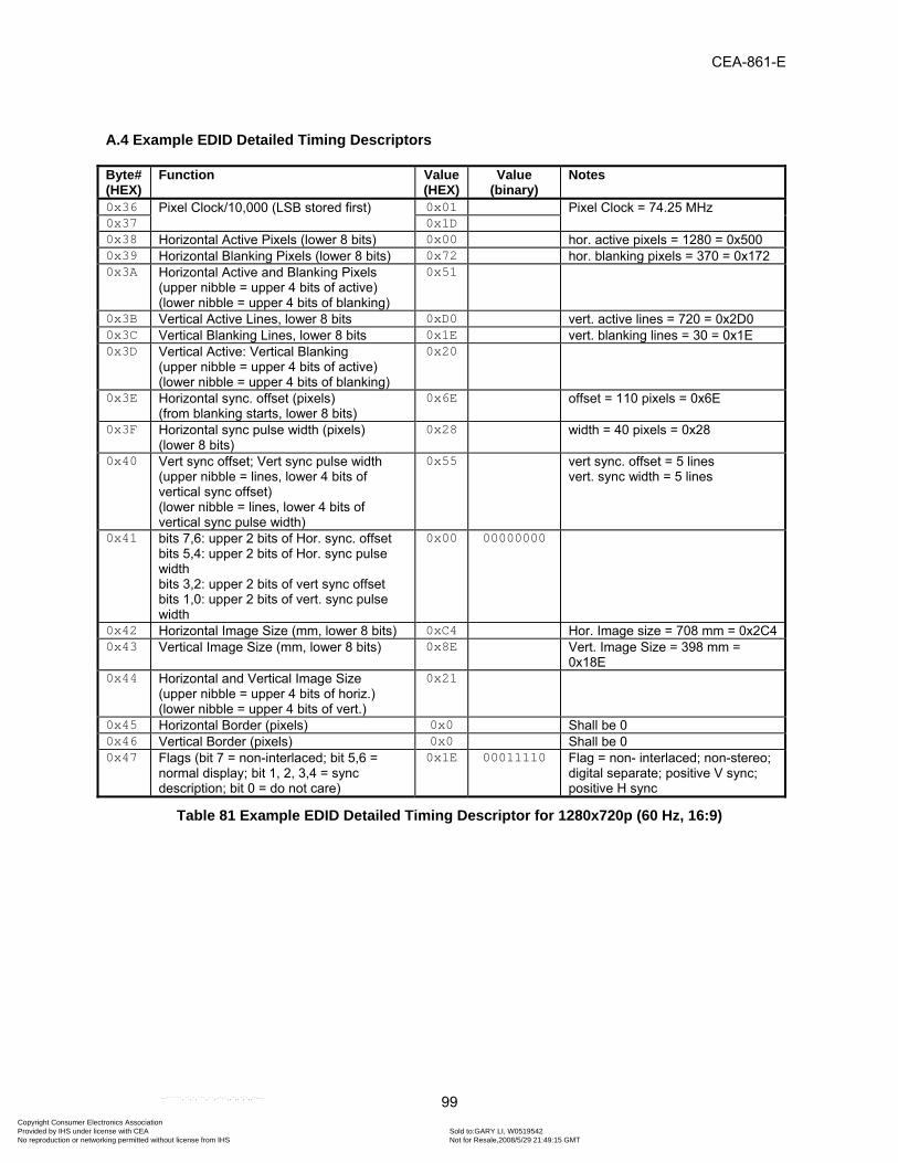
CEA-861-E
99
A.4 Example EDID Detailed Timing Descriptors Byte# (HEX)
Function Value(HEX)
Value(binary)
Notes
0x36 Pixel Clock/10,000 (LSB stored first) 0x01 Pixel Clock = 74.25 MHz 0x37 0x1D 0x38 Horizontal Active Pixels (lower 8 bits) 0x00 hor. active pixels = 1280 = 0x500 0x39 Horizontal Blanking Pixels (lower 8 bits) 0x72 hor. blanking pixels = 370 = 0x172 0x3A Horizontal Active and Blanking Pixels
(upper nibble = upper 4 bits of active) (lower nibble = upper 4 bits of blanking)
0x51
0x3B Vertical Active Lines, lower 8 bits 0xD0 vert. active lines = 720 = 0x2D0 0x3C Vertical Blanking Lines, lower 8 bits 0x1E vert. blanking lines = 30 = 0x1E 0x3D Vertical Active: Vertical Blanking
(upper nibble = upper 4 bits of active) (lower nibble = upper 4 bits of blanking)
0x20
0x3E Horizontal sync. offset (pixels) (from blanking starts, lower 8 bits)
0x6E offset = 110 pixels = 0x6E
0x3F Horizontal sync pulse width (pixels) (lower 8 bits)
0x28 width = 40 pixels = 0x28
0x40 Vert sync offset; Vert sync pulse width (upper nibble = lines, lower 4 bits of vertical sync offset) (lower nibble = lines, lower 4 bits of vertical sync pulse width)
0x55 vert sync. offset = 5 lines vert. sync width = 5 lines
0x41 bits 7,6: upper 2 bits of Hor. sync. offset bits 5,4: upper 2 bits of Hor. sync pulse width bits 3,2: upper 2 bits of vert sync offset bits 1,0: upper 2 bits of vert. sync pulse width
0x00 00000000
0x42 Horizontal Image Size (mm, lower 8 bits) 0xC4 Hor. Image size = 708 mm = 0x2C40x43 Vertical Image Size (mm, lower 8 bits) 0x8E Vert. Image Size = 398 mm =
0x18E 0x44 Horizontal and Vertical Image Size
(upper nibble = upper 4 bits of horiz.) (lower nibble = upper 4 bits of vert.)
0x21
0x45 Horizontal Border (pixels) 0x0 Shall be 0 0x46 Vertical Border (pixels) 0x0 Shall be 0 0x47 Flags (bit 7 = non-interlaced; bit 5,6 =
normal display; bit 1, 2, 3,4 = sync description; bit 0 = do not care)
0x1E 00011110 Flag = non- interlaced; non-stereo; digital separate; positive V sync; positive H sync
Table 81 Example EDID Detailed Timing Descriptor for 1280x720p (60 Hz, 16:9)
Copyright Consumer Electronics Association Provided by IHS under license with CEA Sold to:GARY LI, W0519542
Not for Resale,2008/5/29 21:49:15 GMTNo reproduction or networking permitted without license from IHS
--``````,``,`,```,``,-`-`,,`,,`,`,,`---

CEA-861-E
100
Byte# (Hex)
Function Value(Hex)
Value(binary)
Notes
0x36 Pixel Clock/10,000 (LSB stored first) 0x01 Pixel Clock = 74.25 MHz 0x37 0x1D 0x38 Horizontal Active Pixels (lower 8 bits) 0x80 hor. active pixels = 1920 = 0x780 0x39 Horizontal Blanking Pixels (lower 8 bits) 0x18 hor. blanking pixels = 280 = 0x118 0x3A Horizontal Active and Blanking Pixels
(upper nibble = upper 4 bits of active) (lower nibble = upper 4 bits of blanking)
0x71
0x3B Vertical Active Lines, lower 8 bits 0x1C vert. active lines = 540 = 0x21C 0x3C Vertical Blanking Lines, lower 8 bits 0x16 vert. blanking lines = 22 = 0x169 0x3D Vertical Active: Vertical Blanking
(upper nibble = upper 4 bits of active) (lower nibble = upper 4 bits of blanking)
0x20
0x3E Horizontal sync. offset (pixels) (from blanking starts, lower 8 bits)
0x58 offset = 88 pixels = 0x58
0x3F Horizontal sync pulse width (pixels) (lower 8 bits)
0x2C width = 44 pixels = 0x2C
0x40 Vert. sync offset; Vert. sync pulse width (upper nibble = lines, lower 4 bits of vertical sync offset) (lower nibble = lines, lower 4 bits of vertical sync pulse width)
0x25 vert. sync offset = 2 lines10 vert. sync width = 5 lines
0x41 bits 7,6: upper 2 bits of Hor. sync. offset bits 5,4: upper 2 bits of Hor. sync pulse width bits 3,2: upper 2 bits of vert sync offset bits 1,0: upper 2 bits of vert. sync pulse width
0x00 00000000
0x42 Horizontal Image Size (mm, lower 8 bits) 0xC4 Hor. Image size = 708 mm = 0x2C411
0x43 Vertical Image Size (mm, lower 8 bits) 0x8E Vert. Image Size = 398 mm = 0x18E 0x44 Horizontal and Vertical Image Size
(upper nibble = upper 4 bits of horiz.) (lower nibble = upper 4 bits of vert.)
0x21
0x45 Horizontal Border (pixels) 0x00 Shall be 0 0x46 Vertical Border (pixels) 0x00 Shall be 0 0x47 Flags (bit 7 = interlaced; bit 5,6 = normal
display; bit 1, 2, 3,4 = sync description; bit 0 = do not care)
0x9E 10011110 Flag = interlaced; non-stereo; digital separate; positive V sync; positive H sync
Table 82 Example EDID Detailed Timing Descriptor for 1920x1080i (60 Hz, 16:9)
9 For interlaced display: Field 1 vertical blanking = Vertical Blanking Lines. Field 2 vertical blanking = Vertical Blanking Lines + 1 blanking line. 10 For interlaced display: Field 1 vertical offset = Vertical Sync Offset. Field 2 vertical offset = Vertical Sync Offset + 0.5 lines. 11 Image size is display dependent. Ratio of Horizontal Image Size to Vertical Image Size shall be 16:9 or 4:3.
Copyright Consumer Electronics Association Provided by IHS under license with CEA Sold to:GARY LI, W0519542
Not for Resale,2008/5/29 21:49:15 GMTNo reproduction or networking permitted without license from IHS
--``````,``,`,```,``,-`-`,,`,,`,`,,`---

CEA-861-E
101
Byte# (HEX)
Function Value(HEX)
Value(binary)
Notes
0x36 Pixel Clock/10,000 (LSB stored first) 0x8C Pixel Clock = 27.00 MHz 0x37 0x0A 0x38 Horizontal Active Pixels (lower 8 bits) 0xD0 hor. active pixels = 720 = 0x2D0 0x39 Horizontal Blanking Pixels (lower 8 bits) 0x8A hor. blanking pixels = 138 = 0x8A 0x3A Horizontal Active and Blanking Pixels
(upper nibble = upper 4 bits of active) (lower nibble = upper 4 bits of blanking)
0x20
0x3B Vertical Active Lines, lower 8 bits 0xE0 vert. active lines = 480 = 0x1E0 0x3C Vertical Blanking Lines, lower 8 bits 0x2D vert. blanking lines = 45 = 0x2D 0x3D Vertical Active: Vertical Blanking
(upper nibble = upper 4 bits of active) (lower nibble = upper 4 bits of blanking)
0x10
0x3E Horizontal sync. offset (pixels) (from blanking starts, lower 8 bits)
0x10 offset = 16 pixels = 0x10
0x3F Horizontal sync pulse width (pixels) (lower 8 bits)
0x3E width = 62 pixels = 0x3E
0x40 Vert. sync offset; Vert. sync pulse width (upper nibble = lines, lower 4 bits of vertical sync offset) (lower nibble = lines, lower 4 bits of vertical sync pulse width)
0x96 vert. sync offset = 9 lines vert. sync width = 6 lines
0x41 bits 7,6: upper 2 bits of Hor. sync. offset bits 5,4: upper 2 bits of Hor. sync pulse width bits 3,2: upper 2 bits of vert sync offset bits 1,0: upper 2 bits of vert. sync pulse width
0x00 00000000
0x42 Horizontal Image Size (mm, lower 8 bits) 0x13 Hor. Image size = 531 mm = 0x213 0x43 Vertical Image Size (mm, lower 8 bits) 0x8E Vert. Image Size = 398 mm = 0x18E
(4:3 in this case). 0x44 Horizontal and Vertical Image Size
(upper nibble = upper 4 bits of horiz.) (lower nibble = upper 4 bits of vert.)
0x21
0x45 Horizontal Border (pixels) 0x00 Shall be 0 0x46 Vertical Border (pixels) 0x00 Shall be 0 0x47 Flags (bit 7 = non-interlaced; bit 5,6 =
normal display; bit 1, 2, 3,4 = sync description; bit 0 = do not care)
0x18 00011000 Flag = non-interlaced; non-stereo; digital separate; negative V sync; negative H sync
Table 83 Example EDID Detailed Timing Descriptor for 720x480p (59.94 Hz, 4:3)
Copyright Consumer Electronics Association Provided by IHS under license with CEA Sold to:GARY LI, W0519542
Not for Resale,2008/5/29 21:49:15 GMTNo reproduction or networking permitted without license from IHS
--``````,``,`,```,``,-`-`,,`,,`,`,,`---

CEA-861-E
102
Byte# (HEX)
Function Value(HEX)
Value(binary)
Notes
0x36 Pixel Clock/10,000 (LSB stored first) 0x8C Pixel Clock = 27.00 MHz 0x37 0x0A 0x38 Horizontal Active Pixels (lower 8 bits) 0xD0 hor. active pixels = 720 = 0x2D0 0x39 Horizontal Blanking Pixels (lower 8 bits) 0x8A hor. blanking pixels = 138 = 0x8A 0x3A Horizontal Active and Blanking Pixels
(upper nibble = upper 4 bits of active) (lower nibble = upper 4 bits of blanking)
0x20
0x3B Vertical Active Lines, lower 8 bits 0xE0 vert. active lines = 480 = 0x1E0 0x3C Vertical Blanking Lines, lower 8 bits 0x2D vert. blanking lines = 45 = 0x2D 0x3D Vertical Active: Vertical Blanking
(upper nibble = upper 4 bits of active) (lower nibble = upper 4 bits of blanking)
0x10
0x3E Horizontal sync. offset (pixels) (from blanking starts, lower 8 bits)
0x10 offset = 16 pixels = 0x10
0x3F Horizontal sync pulse width (pixels) (lower 8 bits)
0x3E width = 62 pixels = 0x3E
0x40 Vert sync offset; Vert sync pulse width (upper nibble = lines, lower 4 bits of vertical sync offset) (lower nibble = lines, lower 4 bits of vertical sync pulse width)
0x96 vert sync. offset = 9 lines vert. sync width = 6 lines
0x41 bits 7,6: upper 2 bits of Hor. sync. offset bits 5,4: upper 2 bits of Hor. sync pulse width bits 3,2: upper 2 bits of vert sync offset bits 1,0: upper 2 bits of vert. sync pulse width
0x00 00000000
0x42 Horizontal Image Size (mm, lower 8 bits) 0xC4 Hor. Image size = 708 mm = 0x2C4
0x43 Vertical Image Size (mm, lower 8 bits) 0x8E Vert. Image Size = 398 mm = 0x18E (16:9 in this case).
0x44 Horizontal and Vertical Image Size (upper nibble = upper 4 bits of horiz.) (lower nibble = upper 4 bits of vert.)
0x21
0x45 Horizontal Border (pixels) 0x00 Shall be 0 0x46 Vertical Border (pixels) 0x00 Shall be 0 0x47 Flags (bit 7 = non-interlaced; bit 5,6 =
normal display; bit 1, 2, 3,4 = sync description; bit 0 = do not care)
0x18 00011000 Flag = non-interlaced; non-stereo; digital separate; negative V sync; negative H sync
Table 84 Example EDID Detailed Timing Descriptor for 720x480p (59.94Hz, 16:9)
Copyright Consumer Electronics Association Provided by IHS under license with CEA Sold to:GARY LI, W0519542
Not for Resale,2008/5/29 21:49:15 GMTNo reproduction or networking permitted without license from IHS
--``````,``,`,```,``,-`-`,,`,,`,`,,`---

CEA-861-E
103
Byte# (HEX)
Function Value(HEX)
Value(binary)
Notes
0x36 Pixel Clock/10,000 (LSB stored first) 0x8C Pixel Clock = 27.00 MHz 0x37 0x0A 0x38 Horizontal Active Pixels (lower 8 bits) 0xA0 hor. active pixels = 1440 = 0x5A0 0x39 Horizontal Blanking Pixels (lower 8 bits) 0x14 hor. blanking pixels = 276 = 0x114 0x3A Horizontal Active and Blanking Pixels
(upper nibble = upper 4 bits of active) (lower nibble = upper 4 bits of blanking)
0x51
0x3B Vertical Active Lines, lower 8 bits 0xF0 vert. active lines = 240 = 0xF0 0x3C Vertical Blanking Lines, lower 8 bits 0x16 vert. blanking lines = 22 = 0x16 0x3D Vertical Active: Vertical Blanking
(upper nibble = upper 4 bits of active) (lower nibble = upper 4 bits of blanking)
0x00
0x3E Horizontal sync. offset (pixels) (from blanking starts, lower 8 bits)
0x26 offset = 38 pixels = 0x26
0x3F Horizontal sync pulse width (pixels) (lower 8 bits)
0x7C width = 124 pixels = 0x7C
0x40 Vert sync offset; Vert sync pulse width (upper nibble = lines, lower 4 bits of vertical sync offset) (lower nibble = lines, lower 4 bits of vertical sync pulse width)
0x43 vert sync. offset = 4 lines vert. sync width = 3 lines
0x41 bits 7,6: upper 2 bits of Hor. sync. offset bits 5,4: upper 2 bits of Hor. sync pulse width bits 3,2: upper 2 bits of vert sync offset bits 1,0: upper 2 bits of vert. sync pulse width
0x00 00000000
0x42 Horizontal Image Size (mm, lower 8 bits) 0x13 Hor. Image size = 531 mm = 0x213
0x43 Vertical Image Size (mm, lower 8 bits) 0x8E Vert. Image Size = 398 mm = 0x18E (4:3 in this case).
0x44 Horizontal and Vertical Image Size (upper nibble = upper 4 bits of horiz.) (lower nibble = upper 4 bits of vert.)
0x21
0x45 Horizontal Border (pixels) 0x00 Shall be 0 0x46 Vertical Border (pixels) 0x00 Shall be 0 0x47 Flags (bit 7 = non-interlaced; bit 5,6 =
normal display; bit 1, 2, 3,4 = sync description; bit 0 = do not care)
0x98 10011000 Flag = interlaced; non-stereo; digital separate; negative V sync; negative H sync
Table 85 Example EDID Detailed Timing Descriptor for 720x480i (59.94Hz, 4:3)
Copyright Consumer Electronics Association Provided by IHS under license with CEA Sold to:GARY LI, W0519542
Not for Resale,2008/5/29 21:49:15 GMTNo reproduction or networking permitted without license from IHS
--``````,``,`,```,``,-`-`,,`,,`,`,,`---

CEA-861-E
104
Byte# (HEX)
Function Value(HEX)
Value(binary)
Notes
0x36 Pixel Clock/10,000 (LSB stored first) 0x8C Pixel Clock = 27.00 MHz 0x37 0x0A 0x38 Horizontal Active Pixels (lower 8 bits) 0xA0 hor. active pixels = 1440 = 0x5A0 0x39 Horizontal Blanking Pixels (lower 8 bits) 0x14 hor. blanking pixels = 276 = 0x114 0x3A Horizontal Active and Blanking Pixels
(upper nibble = upper 4 bits of active) (lower nibble = upper 4 bits of blanking)
0x51
0x3B Vertical Active Lines, lower 8 bits 0xF0 vert. active lines = 240 = 0xF0 0x3C Vertical Blanking Lines, lower 8 bits 0x16 vert. blanking lines = 22 = 0x16 0x3D Vertical Active: Vertical Blanking
(upper nibble = upper 4 bits of active) (lower nibble = upper 4 bits of blanking)
0x00
0x3E Horizontal sync. offset (pixels) (from blanking starts, lower 8 bits)
0x26 offset = 38 pixels = 0x26
0x3F Horizontal sync pulse width (pixels) (lower 8 bits)
0x7C width = 124 pixels = 0x7C
0x40 Vert sync offset; Vert sync pulse width (upper nibble = lines, lower 4 bits of vertical sync offset) (lower nibble = lines, lower 4 bits of vertical sync pulse width)
0x43 vert sync. offset = 4 lines vert. sync width = 3 lines
0x41 bits 7,6: upper 2 bits of Hor. sync. offset bits 5,4: upper 2 bits of Hor. sync pulse width bits 3,2: upper 2 bits of vert sync offset bits 1,0: upper 2 bits of vert. sync pulse width
0x00 00000000
0x42 Horizontal Image Size (mm, lower 8 bits) 0xC4 Hor. Image size = 708 mm = 0x2C4
0x43 Vertical Image Size (mm, lower 8 bits) 0x8E Vert. Image Size = 398 mm = 0x18E (16:9 in this case).
0x44 Horizontal and Vertical Image Size (upper nibble = upper 4 bits of horiz.) (lower nibble = upper 4 bits of vert.)
0x21
0x45 Horizontal Border (pixels) 0x00 Shall be 0 0x46 Vertical Border (pixels) 0x00 Shall be 0 0x47 Flags (bit 7 = non-interlaced; bit 5,6 =
normal display; bit 1, 2, 3,4 = sync description; bit 0 = do not care)
0x98 10011000 Flag = interlaced; non-stereo; digital separate; negative V sync; negative H sync
Table 86 Example EDID Detailed Timing Descriptor for 720x480i (59.94Hz, 16:9)
Copyright Consumer Electronics Association Provided by IHS under license with CEA Sold to:GARY LI, W0519542
Not for Resale,2008/5/29 21:49:15 GMTNo reproduction or networking permitted without license from IHS
--``````,``,`,```,``,-`-`,,`,,`,`,,`---

CEA-861-E
105
Byte# (HEX)
Function Value(HEX)
Value(binary)
Notes
0x36 Pixel Clock/10,000 (LSB stored first) 0x01 Pixel Clock = 74.25 MHz 0x37 0x1D 0x38 Horizontal Active Pixels (lower 8 bits) 0x00 hor. active pixels = 1280 = 0x500 0x39 Horizontal Blanking Pixels (lower 8 bits) 0xBC hor. blanking pixels = 700 = 0x2BC 0x3A Horizontal Active and Blanking Pixels
(upper nibble = upper 4 bits of active) (lower nibble = upper 4 bits of blanking)
0x52
0x3B Vertical Active Lines, lower 8 bits 0xD0 vert. active lines = 720 = 0x2D0 0x3C Vertical Blanking Lines, lower 8 bits 0x1E vert. blanking lines = 30 = 0x1E 0x3D Vertical Active: Vertical Blanking
(upper nibble = upper 4 bits of active) (lower nibble = upper 4 bits of blanking)
0x20
0x3E Horizontal sync. offset (pixels) (from blanking starts, lower 8 bits)
0xB8 offset = 440 pixels = 0x1B8
0x3F Horizontal sync pulse width (pixels) (lower 8 bits)
0x28 width = 40 pixels = 0x28
0x40 Vert sync offset; Vert sync pulse width (upper nibble = lines, lower 4 bits of vertical sync offset) (lower nibble = lines, lower 4 bits of vertical sync pulse width)
0x55 vert sync. offset = 5 lines vert. sync width = 5 lines
0x41 bits 7,6: upper 2 bits of Hor. sync. offset bits 5,4: upper 2 bits of Hor. sync pulse width bits 3,2: upper 2 bits of vert sync offset bits 1,0: upper 2 bits of vert. sync pulse width
0x40 01000000
0x42 Horizontal Image Size (mm, lower 8 bits) 0xC4 Hor. Image size = 708 mm = 0x2C40x43 Vertical Image Size (mm, lower 8 bits) 0x8E Vert. Image Size = 398 mm =
0x18E 0x44 Horizontal and Vertical Image Size
(upper nibble = upper 4 bits of horiz.) (lower nibble = upper 4 bits of vert.)
0x21
0x45 Horizontal Border (pixels) 0x00 Shall be 0 0x46 Vertical Border (pixels) 0x00 Shall be 0 0x47 Flags (bit 7 = non-interlaced; bit 5,6 =
normal display; bit 1, 2, 3,4 = sync description; bit 0 = do not care)
0x1E 00011110 Flag = non- interlaced; non-stereo; digital separate; positive V sync; positive H sync
Table 87 Example EDID Detailed Timing Descriptor for 1280x720p (50 Hz, 16:9)
Copyright Consumer Electronics Association Provided by IHS under license with CEA Sold to:GARY LI, W0519542
Not for Resale,2008/5/29 21:49:15 GMTNo reproduction or networking permitted without license from IHS
--``````,``,`,```,``,-`-`,,`,,`,`,,`---

CEA-861-E
106
Byte# (HEX)
Function Value(HEX)
Value(binary)
Notes
0x36 Pixel Clock/10,000 (LSB stored first) 0x01 Pixel Clock = 74.25 MHz 0x37 0x1D 0x38 Horizontal Active Pixels (lower 8 bits) 0x80 Hor. active pixels = 1920 = 0x780 0x39 Horizontal Blanking Pixels (lower 8 bits) 0xD0 hor. blanking pixels = 720 = 0x2D0 0x3A Horizontal Active and Blanking Pixels
(upper nibble = upper 4 bits of active) (lower nibble = upper 4 bits of blanking)
0x72
0x3B Vertical Active Lines, lower 8 bits 0x1C vert. active lines = 540 = 0x21C 0x3C Vertical Blanking Lines, lower 8 bits 0x16 vert. blanking lines = 22 = 0x16 0x3D Vertical Active: Vertical Blanking
(upper nibble = upper 4 bits of active) (lower nibble = upper 4 bits of blanking)
0x20
0x3E Horizontal sync. offset (pixels) (from blanking starts, lower 8 bits)
0x10 offset = 528 pixels = 0x210
0x3F Horizontal sync pulse width (pixels) (lower 8 bits)
0x2C width = 44 pixels = 0x2C
0x40 Vert sync offset; Vert sync pulse width (upper nibble = lines, lower 4 bits of vertical sync offset) (lower nibble = lines, lower 4 bits of vertical sync pulse width)
0x25 vert sync. offset = 2 lines vert. sync width = 5 lines
0x41 bits 7,6: upper 2 bits of Hor. sync. offset bits 5,4: upper 2 bits of Hor. sync pulse width bits 3,2: upper 2 bits of vert sync offset bits 1,0: upper 2 bits of vert. sync pulse width
0x80 10000000
0x42 Horizontal Image Size (mm, lower 8 bits) 0xC4 Hor. Image size = 708 mm = 0x2C4 0x43 Vertical Image Size (mm, lower 8 bits) 0x8E Vert. Image Size = 398 mm = 0x18E 0x44 Horizontal and Vertical Image Size
(upper nibble = upper 4 bits of horiz.) (lower nibble = upper 4 bits of vert.)
0x21
0x45 Horizontal Border (pixels) 0x00 Shall be 0 0x46 Vertical Border (pixels) 0x00 Shall be 0 0x47 Flags (bit 7 = interlaced; bit 5,6 = normal
display; bit 1, 2, 3,4 = sync description; bit 0 = do not care)
0x9E 10011110 Flag = interlaced; non-stereo; digital separate; positive V sync; positive H sync
Table 88 Example EDID Detailed Timing Descriptor for 1920x1080i (50 Hz, 16:9)
Copyright Consumer Electronics Association Provided by IHS under license with CEA Sold to:GARY LI, W0519542
Not for Resale,2008/5/29 21:49:15 GMTNo reproduction or networking permitted without license from IHS
--``````,``,`,```,``,-`-`,,`,,`,`,,`---

CEA-861-E
107
Byte# (HEX)
Function Value(HEX)
Value(binary)
Notes
0x36 Pixel Clock/10,000 (LSB stored first) 0x8C Pixel Clock = 27.00 MHz 0x37 0x0A 0x38 Horizontal Active Pixels (lower 8 bits) 0xD0 hor. active pixels = 720 = 0x2D0 0x39 Horizontal Blanking Pixels (lower 8 bits) 0x90 hor. blanking pixels = 144 = 0x90 0x3A Horizontal Active and Blanking Pixels
(upper nibble = upper 4 bits of active) (lower nibble = upper 4 bits of blanking)
0x20
0x3B Vertical Active Lines, lower 8 bits 0x40 vert. active lines = 576 = 0x240 0x3C Vertical Blanking Lines, lower 8 bits 0x31 vert. blanking lines = 49 = 0x31 0x3D Vertical Active: Vertical Blanking
(upper nibble = upper 4 bits of active) (lower nibble = upper 4 bits of blanking)
0x20
0x3E Horizontal sync. offset (pixels) (from blanking starts, lower 8 bits)
0x0C offset = 12 pixels = 0x0C
0x3F Horizontal sync pulse width (pixels) (lower 8 bits)
0x40 Width = 64 pixels = 0x40
0x40 Vert sync offset; Vert sync pulse width (upper nibble = lines, lower 4 bits of vertical sync offset) (lower nibble = lines, lower 4 bits of vertical sync pulse width)
0x55 vert sync. offset = 5 lines vert. sync width = 5 lines
0x41 bits 7,6: upper 2 bits of Hor. sync. offset bits 5,4: upper 2 bits of Hor. sync pulse width bits 3,2: upper 2 bits of vert sync offset bits 1,0: upper 2 bits of vert. sync pulse width
0x00 00000000
0x42 Horizontal Image Size (mm, lower 8 bits) 0x13 Hor. Image size = 531 mm = 0x213
0x43 Vertical Image Size (mm, lower 8 bits) 0x8E Vert. Image Size = 398 mm = 0x18E (4:3 in this case).
0x44 Horizontal and Vertical Image Size (upper nibble = upper 4 bits of horiz.) (lower nibble = upper 4 bits of vert.)
0x21
0x45 Horizontal Border (pixels) 0x00 Shall be 0 0x46 Vertical Border (pixels) 0x00 Shall be 0 0x47 Flags (bit 7 = non-interlaced; bit 5,6 =
normal display; bit 1, 2, 3,4 = sync description; bit 0 = do not care)
0x18 00011000 Flag = non-interlaced; non-stereo; digital separate; negative V sync; negative H sync
Table 89 Example EDID Detailed Timing Descriptor for 720x576p (50 Hz, 4:3)
Copyright Consumer Electronics Association Provided by IHS under license with CEA Sold to:GARY LI, W0519542
Not for Resale,2008/5/29 21:49:15 GMTNo reproduction or networking permitted without license from IHS
--``````,``,`,```,``,-`-`,,`,,`,`,,`---

CEA-861-E
108
Byte# (HEX)
Function Value(HEX)
Value(binary)
Notes
0x36 Pixel Clock/10,000 (LSB stored first) 0x8C Pixel Clock = 27.00 MHz 0x37 0x0A 0x38 Horizontal Active Pixels (lower 8 bits) 0xD0 hor. active pixels = 720 = 0x2D0 0x39 Horizontal Blanking Pixels (lower 8 bits) 0x90 hor. blanking pixels = 144 = 0x90 0x3A Horizontal Active and Blanking Pixels
(upper nibble = upper 4 bits of active) (lower nibble = upper 4 bits of blanking)
0x20
0x3B Vertical Active Lines, lower 8 bits 0x40 vert. active lines = 576 = 0x240 0x3C Vertical Blanking Lines, lower 8 bits 0x31 vert. blanking lines = 49 = 0x31 0x3D Vertical Active: Vertical Blanking
(upper nibble = upper 4 bits of active) (lower nibble = upper 4 bits of blanking)
0x20
0x3E Horizontal sync. offset (pixels) (from blanking starts, lower 8 bits)
0x0C offset = 12 pixels = 0x0C
0x3F Horizontal sync pulse width (pixels) (lower 8 bits)
0x40 width = 64 pixels = 0x40
0x40 Vert sync offset; Vert sync pulse width (upper nibble = lines, lower 4 bits of vertical sync offset) (lower nibble = lines, lower 4 bits of vertical sync pulse width)
0x55 vert sync. offset = 5 lines vert. sync width = 5 lines
0x41 bits 7,6: upper 2 bits of Hor. sync. offset bits 5,4: upper 2 bits of Hor. sync pulse width bits 3,2: upper 2 bits of vert sync offset bits 1,0: upper 2 bits of vert. sync pulse width
0x00 00000000
0x42 Horizontal Image Size (mm, lower 8 bits) 0xC4 Hor. Image size = 708 mm = 0x2C4 0x43 Vertical Image Size (mm, lower 8 bits) 0x8E Vert. Image Size = 398 mm = 0x18E
(16:9 in this case). 0x44 Horizontal and Vertical Image Size
(upper nibble = upper 4 bits of horiz.) (lower nibble = upper 4 bits of vert.)
0x21
0x45 Horizontal Border (pixels) 0x00 Shall be 0 0x46 Vertical Border (pixels) 0x00 Shall be 0 0x47 Flags (bit 7 = non-interlaced; bit 5,6 =
normal display; bit 1, 2, 3,4 = sync description; bit 0 = do not care)
0x18 00011000 Flag = non-interlaced; non-stereo; digital separate; negative V sync; negative H sync
Table 90 Example EDID Detailed Timing Descriptor for 720x576p (50 Hz, 16:9)
Copyright Consumer Electronics Association Provided by IHS under license with CEA Sold to:GARY LI, W0519542
Not for Resale,2008/5/29 21:49:15 GMTNo reproduction or networking permitted without license from IHS
--``````,``,`,```,``,-`-`,,`,,`,`,,`---

CEA-861-E
109
Byte# (HEX)
Function Value(HEX)
Value(binary)
Notes
0x36 Pixel Clock/10,000 (LSB stored first) 0x8C Pixel Clock = 27.00 MHz 0x37 0x0A 0x38 Horizontal Active Pixels (lower 8 bits) 0xA0 hor. active pixels = 1440 = 0x5A0 0x39 Horizontal Blanking Pixels (lower 8 bits) 0x20 hor. blanking pixels = 288 = 0x120 0x3A Horizontal Active and Blanking Pixels
(upper nibble = upper 4 bits of active) (lower nibble = upper 4 bits of blanking)
0x51
0x3B Vertical Active Lines, lower 8 bits 0x20 vert. active lines = 288 = 0x120 0x3C Vertical Blanking Lines, lower 8 bits 0x18 vert. blanking lines = 24 = 0x18 0x3D Vertical Active: Vertical Blanking
(upper nibble = upper 4 bits of active) (lower nibble = upper 4 bits of blanking)
0x10
0x3E Horizontal sync. offset (pixels) (from blanking starts, lower 8 bits)
0x18 offset = 24 pixels = 0x18
0x3F Horizontal sync pulse width (pixels) (lower 8 bits)
0x7E Width = 126 pixels = 0x7C
0x40 Vert sync offset; Vert sync pulse width (upper nibble = lines, lower 4 bits of vertical sync offset) (lower nibble = lines, lower 4 bits of vertical sync pulse width)
0x23 vert sync. offset = 2 lines vert. sync width = 3 lines
0x41 bits 7,6: upper 2 bits of Hor. sync. offset bits 5,4: upper 2 bits of Hor. sync pulse width bits 3,2: upper 2 bits of vert sync offset bits 1,0: upper 2 bits of vert. sync pulse width
0x00 00000000
0x42 Horizontal Image Size (mm, lower 8 bits) 0x13 Hor. Image size = 531 mm = 0x213
0x43 Vertical Image Size (mm, lower 8 bits) 0x8E Vert. Image Size = 398 mm = 0x18E (4:3 in this case).
0x44 Horizontal and Vertical Image Size (upper nibble = upper 4 bits of horiz.) (lower nibble = upper 4 bits of vert.)
0x21
0x45 Horizontal Border (pixels) 0x00 Shall be 0 0x46 Vertical Border (pixels) 0x00 Shall be 0 0x47 Flags (bit 7 = non-interlaced; bit 5,6 =
normal display; bit 1, 2, 3,4 = sync description; bit 0 = do not care)
0x98 10011000 Flag = interlaced; non-stereo; digital separate; negative V sync; negative H sync
Table 91 Example EDID Detailed Timing Descriptor for 720x576i (50 Hz, 4:3)
Copyright Consumer Electronics Association Provided by IHS under license with CEA Sold to:GARY LI, W0519542
Not for Resale,2008/5/29 21:49:15 GMTNo reproduction or networking permitted without license from IHS
--``````,``,`,```,``,-`-`,,`,,`,`,,`---

CEA-861-E
110
Byte# (HEX)
Function Value(HEX)
Value(binary)
Notes
0x36 Pixel Clock/10,000 (LSB stored first) 0x8C Pixel Clock = 27.00 MHz 0x37 0x0A 0x38 Horizontal Active Pixels (lower 8 bits) 0xA0 hor. active pixels = 1440 = 0x5A0 0x39 Horizontal Blanking Pixels (lower 8 bits) 0x20 hor. blanking pixels = 288 = 0x120 0x3A Horizontal Active and Blanking Pixels
(upper nibble = upper 4 bits of active) (lower nibble = upper 4 bits of blanking)
0x51
0x3B Vertical Active Lines, lower 8 bits 0x20 vert. active lines = 288 = 0x120 0x3C Vertical Blanking Lines, lower 8 bits 0x18 vert. blanking lines = 24 = 0x18 0x3D Vertical Active: Vertical Blanking
(upper nibble = upper 4 bits of active) (lower nibble = upper 4 bits of blanking)
0x10
0x3E Horizontal sync. offset (pixels) (from blanking starts, lower 8 bits)
0x18 offset = 24 pixels = 0x18
0x3F Horizontal sync pulse width (pixels) (lower 8 bits)
0x7E Width = 126 pixels = 0x7E
0x40 Vert sync offset; Vert sync pulse width (upper nibble = lines, lower 4 bits of vertical sync offset) (lower nibble = lines, lower 4 bits of vertical sync pulse width)
0x23 vert sync. offset = 2 lines vert. sync width = 3 lines
0x41 bits 7,6: upper 2 bits of Hor. sync. offset bits 5,4: upper 2 bits of Hor. sync pulse width bits 3,2: upper 2 bits of vert sync offset bits 1,0: upper 2 bits of vert. sync pulse width
0x00 00000000
0x42 Horizontal Image Size (mm, lower 8 bits) 0xC4 Hor. Image size = 708 mm = 0x2C4
0x43 Vertical Image Size (mm, lower 8 bits) 0x8E Vert. Image Size = 398 mm = 0x18E (16:9 in this case).
0x44 Horizontal and Vertical Image Size (upper nibble = upper 4 bits of horiz.) (lower nibble = upper 4 bits of vert.)
0x21
0x45 Horizontal Border (pixels) 0x00 Shall be 0 0x46 Vertical Border (pixels) 0x00 Shall be 0 0x47 Flags (bit 7 = non-interlaced; bit 5,6 =
normal display; bit 1, 2, 3,4 = sync description; bit 0 = do not care)
0x98 10011000 Flag = interlaced; non-stereo; digital separate; negative V sync; negative H sync
Table 92 Example EDID Detailed Timing Descriptor for 720x576i (50 Hz, 16:9)
Copyright Consumer Electronics Association Provided by IHS under license with CEA Sold to:GARY LI, W0519542
Not for Resale,2008/5/29 21:49:15 GMTNo reproduction or networking permitted without license from IHS
--``````,``,`,```,``,-`-`,,`,,`,`,,`---

CEA-861-E
111
Annex B Application to DVI 1.0 (Normative) All mandatory aspects of DVI 1.0 [4] shall be implemented with the exception of those expressly identified as optional or informative when DVI 1.0 is used to implement CEA-861-E. DVI does not support transport of CEA InfoFrames, audio or YCBCR pixel data. However, CEA-861-E can still be implemented on DVI 1.0 (with reduced functionality) as explained at the beginning of Section 6. The EDID content shall comply with EDID data structure Version 1, Revision 3 [10]. All sections in Annex B are normative when DVI 1.0 is used to implement CEA-861-E except as otherwise noted.
B.1 Connector and Cable The connector used shall be DVI-Digital, Single Link [4]. The cable, if supplied with the product, shall be compliant with the DVI specification at maximum pixel clock frequency compatible with the product.
B.2 Digital Content Protection High-bandwidth Digital Content Protection (HDCP) [3] is available to authenticate display devices and encrypt content transmitted across the DVI interface.
Copyright Consumer Electronics Association Provided by IHS under license with CEA Sold to:GARY LI, W0519542
Not for Resale,2008/5/29 21:49:15 GMTNo reproduction or networking permitted without license from IHS
--``````,``,`,```,``,-`-`,,`,,`,`,,`---

CEA-861-E
112
Annex C Application to Open LDI (Normative) All mandatory aspects of OpenLDI 0.95 [8] shall be implemented with the exception of those expressly identified as optional or informative in that standard when OpenLDI 0.95 is used to implement CEA-861-E. It should be noted that at the time of this writing, a version of OpenLDI that supports transport of CEA InfoFrames was not available. However, CEA-861-E can still be implemented on OpenLDI 0.95 (with reduced functionality) as explained in Section 6. All sections in this Annex are normative when OpenLDI 0.95 is used to implement CEA-861-E except as otherwise noted.
C.1 Open LDI Data and Control Signals OpenLDI has two options for display synchronization: a) DC Balance Mode: b) Non DC Balance Mode: In DC Balance mode synchronization is accomplished by transmitting control signals during the Display blanking intervals as shown in Figure 7.
Figure 7 OpenLDI Synchronization In the single or dual LVDS bus mode (24 or 48 bit Total), the control signals are transmitted over 7 transition words on specific output signals during the blanking period as indicated in Table 93.
Control Signal Signal Level Output Signal Data PatternDE High CLK1 and CLK2 1111000 or 1110000
Low 1111100 or 1100000 HSYNC High A0 1100000 or 1111100
Low 1110000 or 1111000 VSYNC High A1 1100000 or 1111100
Low 1110000 or 1111000
Table 93 OpenLDI Control Signals
C.2 Non DC Balanced Mode Control signals are transmitted as part the LVDS serialized data stream. The controls signals are then de-serialized and regenerated at the receiver outputs to the EDTV/HDTV.
C.3 OpenLDI Cabling Information An OpenLDI cable assembly shall consist of a cable meeting the requirements of this section with an OpenLDI plug on each end or an OpenLDI plug on one end and the other end permanently affixed to the display device. Acceptable cables for OpenLDI may use either shielded or unshielded twisted pairs. It is up to the manufacturer of the OpenLDI equipment to use the grade and type of cable required to meet applicable regulatory requirements. Adherence to CEA-861-E does not guarantee regulatory compliance.
Data Enable
LVDS TxOUT
Active Display
Active Display
Blanking Time
Pixel Data
Pixel Data
Control Signals
Copyright Consumer Electronics Association Provided by IHS under license with CEA Sold to:GARY LI, W0519542
Not for Resale,2008/5/29 21:49:15 GMTNo reproduction or networking permitted without license from IHS
--``````,``,`,```,``,-`-`,,`,,`,`,,`---

CEA-861-E
113
When the OpenLDI is an interface internal to an assembly and not accessible externally, the OpenLDI cable may be replaced with any cable or connection means appropriate to the requirements of the assembly.
C.3.1 Cable Length The maximum cable length shall be 10m.
C.3.2 Number of Signal Conductors The OpenLDI cable shall comprise 11 twisted pairs and 10 individual conductors.
C.3.3 Wire Gauge Each conductor in an OpenLDI cable shall be no less than 28AWG.
C.3.4 Conductor Resistance The resistance of a single conductor of an OpenLDI cable shall not exceed 4Ω when the conductor is of the maximum length specified in CEA-861-E.
C.3.5 Insulation Each conductor in the cable shall be separately insulated. The minimum insulation resistance shall be 1GΩ.
C.3.6 Shield Requirement The OpenLDI cable shall be encompassed by a single shield, surrounding all conductors in the cable. The shield shall provide a minimum of 90% coverage. For shielded twisted pair cable, each twisted pair shall be shielded individually. Each shield shall provide a minimum of 90% coverage.
C.3.7 Single Twisted Pair Transmission Skew The differential time of transmission (single pair transmission skew) of a pulse through a single differential pair in an OpenLDI cable shall not exceed 300ps.
C.3.8 Multiple Twisted Pair Transmission Skew The differential time of transmission (pair to pair transmission skew) of a pulse through any two differential pairs in an OpenLDI cable shall not exceed 1 bit time.
C.3.9 USB Cable Requirements The conductors used for transmission of USB signals on the OpenLDI cable shall meet the requirements stated in the Universal Serial Bus Specification, Version 1.0, January 15, 1996.
C.3.10 DDC Cable Requirements The conductors used for transmission of DDC signals on the OpenLDI cable shall meet the requirements stated in the VESA Display Data Channel Command Interface (DDC/CI) Standard, Version 1, August 14, 1998 [11]. More information on the connector is available in Section 7.2 of the OpenLDI specification [8].
Copyright Consumer Electronics Association Provided by IHS under license with CEA Sold to:GARY LI, W0519542
Not for Resale,2008/5/29 21:49:15 GMTNo reproduction or networking permitted without license from IHS
--``````,``,`,```,``,-`-`,,`,,`,`,,`---

CEA-861-E
114
Annex D Application to HDMI (Informative) .
D.1 InfoPackets HDMI carries each InfoFrame in its own HDMI packet. The HDMI packet type for an InfoFrame packet is equal to 0x80+InfoFrame Type, therefore, only InfoFrames with Types less than 0x80 may be transmitted. Including Type, Version, and Length fields, InfoFrames of at most 30 bytes are supported. A checksum is present in each InfoFrame. Refer to the HDMI Specification for more detail on the packetization of InfoFrames.
D.2 EDID A sink using an HDMI input shall contain an EDID consisting of a single E-EDID Version 1, Revision 3 block and at least one CEA Extension version 3. A sink that supports either type of YCBCR pixel data (4:2:2 or 4:4:4) shall support both types and therefore shall set both bits 4 and 5 of byte 3 of all CEA EDID Extensions within the EDID. A sink that does not support YCBCR pixel data shall have both bits 4 and 5 clear. See D.6 for an example. If the sink supports any type of digital audio on this interface, then it shall also support Basic Audio and shall indicate this by setting the Basic Audio bit (bit 6). Bit 7 of byte 3 shall be set if the sink underscans IT video formats by default.
D.3 Audio HDMI [50] is capable of supporting a variety of audio formats, including uncompressed digital audio (PCM), in an IEC 60958-3 [13] compliant stream at up to 8 channels, up to 192 kHz and up to 24 bits/sample, and compressed digital audio, in an IEC 61937-2 [72] compliant stream, up to 192 kHz. HDMI [50] relies on the defined audio discovery mechanisms present in the CEA EDID Extension Version 3. The Audio InfoFrame, the IEC 60958-3 [13] “Channel Status” bits, and the IEC 61937-2 [72] “Burst Info” bits are used to describe the transmitted audio stream. The Audio InfoFrame CT (coding type), SS (sample size) and SF (sample frequency) fields are required to be 0 (“Refer to Stream Header”) to avoid redundancy with the same data already contained within the IEC 60958-3 [13] stream data.
D.4 HDCP High-bandwidth Digital Content Protection (HDCP) version 1.1 [3] or later, is available to protect the audio and video data carried on an HDMI link.
D.5 Additional Information HDMI information is available from HDMI Licensing (see Section 2.1.2.2). HDCP information is available from Digital-CP, LLC (see Section 2.1.1.2).
D.6 Example EDID Using Elements of CEA Block Tag Extension (Applicable to HDMI) Table 99 contains an example implementation of EDID utilizing elements of the CEA Block Tag Extension that were not addressed in Annex A. These elements are Short Video Descriptors, Audio Descriptors, Speaker Allocation Block, and a Vendor-Specific Data Block. This example is applicable to HDMI implementations. Elements of the Example EDID are addressed individually, in the following subsections.
D.6.1 First Monitor Descriptor (Monitor Name) and Second Monitor Descriptor (Monitor Range Limits) Although Annex A requires that two of the four 18-byte detailed timing descriptors be a Monitor Name Descriptor and a Monitor Descriptor, it is possible that implementations designed for Personal Computers (e.g., multimedia applications), may contain a different set of data. For that reason, sources adhering to
Copyright Consumer Electronics Association Provided by IHS under license with CEA Sold to:GARY LI, W0519542
Not for Resale,2008/5/29 21:49:15 GMTNo reproduction or networking permitted without license from IHS
--``````,``,`,```,``,-`-`,,`,,`,`,,`---

CEA-861-E
115
CEA-861-E should be designed without dependency upon specific data within these blocks that prevent collection and interpretation of subsequent data blocks.
D.6.2 Extension Flag and Checksum The Extension Flag and Checksum are defined the same as in Annex A.
D.6.3 CEA Extension Header (Block 1) The CEA Extension Header is a four-data bytes located in address range 0x80 through 0x83. The first byte is the tag used to identify the extension. The number assigned by VESA to this tag is 0x02. Following the CEA Extension Tag is the Revision Number location. In this example, the Revision Number is set to 0x03. Please note that all Revision numbers are backward compatible. Sources should not have a dependency upon Revision Numbers. Table 94 contains data based upon the tables presented in this Annex. In this example, the CEA Extension Tag is located at address 0x80 followed by Revision Number, Byte Number Offset, and Reserved (i.e., 0x00). The data is set as prescribed by CEA-861-E. Address Hex
Example Data Hex Dec
Name of Block Description Remarks
0x80 0x02 2 CEA Extension Header Tag Block One 0x81 0x03 3 Revision Number Start of CEA Block Tag
Extension 0x82 0x1A 26 Byte Offset 0x83 0x71 113 Global Declarations DTV, YCBCR (4:4:4), YCBCR
(4:2:2)
Table 94 CEA Extension Header (Block 1)
D.6.4 CEA Data Block Collection The CEA Data Block Collection is within the CEA Extension Block and declares CEA Short Video Descriptors, Audio capabilities, Speaker configuration, a Vendor Specific Block that requires an Identifier code, and a Vendor Specific Payload bock that is used to carry additional and optional data. As noted in Section 7.5, the Data Block ordering sequence is not constrained and various combinations are possible; and therefore, the examples provided herein are based upon one possible combination.
D.6.5 Video Data Block The purpose of this block is for listing Short Video Descriptors (SVDs). Short Video Descriptors are used to declare video formats with one byte as contrasted with 18 bytes for Detailed Timing Descriptors, which is useful in economizing memory space. The preferred SVD is listed first. Subsequent SVDs are of decreasing preference. As defined in Table 40 (General Tag Format), the first byte is used to signify a Video Tag Code and Payload Length. Bits 5 to 7 designate the Tag Code and payload length is defined by bits 0 to 4. The payload byte structure is defined in Table 44. Bits 0 through 6 are used for a Video Identification Codes as defined in Table 4; and bit 7 (MSB) is a marker bit called “Native.” If bit 7 is set to ‘1’, the format is a “Native format” (see Section 2.2), and if set to ‘zero’ the format is not “Native.” In the example, as shown in Table 95, bits 5 through 7 located in address 0x84 are set to Tag Code 2 (0x04) designating a Video Data Block; and bits 0 to 4 is set to 0x7 indicating seven bytes of data payload. Addresses 0x85 through 0x8B contain one discrete Short Video Descriptor code per byte.
Copyright Consumer Electronics Association Provided by IHS under license with CEA Sold to:GARY LI, W0519542
Not for Resale,2008/5/29 21:49:15 GMTNo reproduction or networking permitted without license from IHS
--``````,``,`,```,``,-`-`,,`,,`,`,,`---

CEA-861-E
116
Address Hex
Example Data Hex Dec
Name of Block Description Remarks
0x84 0x47 71 Video Data Block
Start of data block collection. Includes Tag Code and length of following data block payload
0x47 = Video Block (code = 2) and seven bytes of data payload
0x85 0x85 132 1st Short Video Descriptor 1920x1080i @ 59.94/60 Hz 16:9 Native Mode
0x86 0x02 2 2nd Short Video Descriptor 720x480p 59.94/60 Hz 4:3 0x87 0x03 3 3rd Short Video Descriptor 720x480p 59.94/60 Hz 16:9 0x88 0x04 4 4th Short Video Descriptor 1280x720p 59.94/60 Hz 16:9 0x89 0x06 6 5th Short Video Descriptor 720(1440)x480i 59.94/60 Hz 4:3 0x8A 0x07 7 6th Short Video Descriptor 720(1440)x480i 59.94/60 Hz 16:9 0x8B 0x01 1 7th Short Video Descriptor 640x480p 59.94/60 Hz 4:3
Table 95 Video Data Block
D.6.6 CEA Audio Block The Audio Data Block is used to declare format, frequency, and bit-rate. The structure of this table is defined in Table 26 with subsequent tables addressing the General Tag Format, Short Audio Descriptors, and Audio Format Codes. Multiple, Short Audio Descriptors may be used in this block. The first byte in this block is the General Format Tag and is the same structure as the Video Data Block as defined in Table 27, General Tag Format. The Tag Code occupies bits 5 and 7; and Payload Length is placed in bits 0 through 4. Audio Tag Codes are listed in Table 34, Audio Format Codes. Three bytes of data are used for each Short Audio Descriptor. Short Audio Descriptors are defined in Table 45 through Table 49; with Table 45 dealing with Linear PCM Audio and compressed audio formats in the remaining tables. Each Descriptor consists of three data bytes. In Table 96, as with the Video Data Block, the first byte (0x8C) is used to indicate block type and payload length in bytes. Audio Tag Code 1 (0x02) is placed in bits 3 and 7; and bits 0 to 4 contains 0x3 for a payload of three bytes. The Short Audio Descriptor begins at address 0x8D and ends with 0x8F. In the first byte of the descriptor, bit 7 is reserved and set to ‘zero’. Bits 3 through 6 contain the Audio Format code as defined in Table 34; in this example Code 1 for Linear PCM is indicated with bit 6…3 set to ‘0001’. Bits 0 through 2 designate the maximum number of channels as one channel audio (0x1). The second descriptor byte uses seven bits to declare frequency characteristics. Frequencies of 32 kHz, 44.1 kHz, and 48 kHz are indicated by the 0x07 as defined in Table 45. In address 0x8E; and in the next address 0x07 is used to declare bit-rates of 16, 20, and 24 bit audio per Table 45. This example does not illustrate Short Audio Descriptors for compressed audio formats. Address Hex
Example Data Hex Dec
Name of Block Description Remarks
0x8C 0x23 35 Audio Data Block Start of Audio Block 0x23 = Audio Block (code = 1) and three bytes of data payload.
0x8D 0x09 9 Audio Format Code 1 = Linear PCM (IEC 60985) 0x8E 0x07 7 Frequency 0x07 = 32 kHz, 44.1 kHz, 48 kHz 0x8F 0x07 7 Bit Rate 0x07 = 16 bit, 20 bit, 24 bit
Table 96 Audio Data Block
D.6.7 Speaker Allocation Block The Speaker Allocation Data Block is used to declare number of speakers and configuration. As with preceding blocks a Tag Code and payload length are designated in the first data byte. The data block payload begins with the second byte and is used to indicate speaker count and configuration (see Table 50). The last payload byte is set to zero.
Copyright Consumer Electronics Association Provided by IHS under license with CEA Sold to:GARY LI, W0519542
Not for Resale,2008/5/29 21:49:15 GMTNo reproduction or networking permitted without license from IHS
--``````,``,`,```,``,-`-`,,`,,`,`,,`---

CEA-861-E
117
In Table 97, address 0x90 contains a value 0x83 which designates the beginning of the Speaker Allocation Block and data payload. In this example, the Speaker Allocation Data Block is indicated by Code 4 per Table 50. The data payload is set to three bytes. At address 0x91 FL/FR (2 Channel Stereo) is chosen by setting the bits to 0x01. The two remaining addresses have the bits set to zero as required by Table 40. Address Hex
Example Data Hex Dec
Name of Block Description Remarks
0x90 0x83 131 Speaker Allocation Block Start of Speaker Allocation 0x83 =Speaker Allocation Data Block (code = 4) and three bytes of data payload.
0x91 0x01 1 Speaker Designation 0x01 = FL / FR (2 Channel Stereo.)
0x92 0x00 0 Speaker Designation Bits 0 to 2 0x93 0x00 0 Reserved Always zero
Table 97 Speaker Data Block
D.6.8 Vendor Specific Block The Vendor Specific Data Block was originally intended as an option to place data not specified by CEA-861-E; data that a manufacturer may care to use. However, the HDMI specification makes requirements that are addressed below. Users are advised to treat this data block with care. The first address requires a Tag Code and data payload length in the first byte. The next three addresses house a 24-bit IEEE Registration Identifier (three bytes); and a Vendor Specific Payload in the remaining bytes. In the case of HDMI compliant devices the IEEE Registration is used as an ‘HDMI Identifier.’ After the HDMI Identifier two bytes are used to identify the port configuration. Users are advised to refer to the HDMI specification for details. For the purposes of this example the HDMI Identifier and Physical Source Address are presented. As shown in Table 98, the first address, 0x94, the Tag Code is listed as ‘3’ and the payload length is set to ‘5’ bytes. The second, third and fourth bytes, addresses 0x95, 0x96 and 0x97, contain the HDMI LLC’s 24-bit IEEE registration Organizationally Unique Identifier (OUI) 0x00030C, which is coded least significant byte first. The Physical Source Address is found in address 0x98 and 0x99 and according to the HDMI specification, the two bytes are used as Identity Port Configuration with 0x1000 indicating a single port sink. The last byte in the data payload or Vendor Specific Payload address is set to zero. Address Hex
Example Data Hex Dec
Name of Block Description Remarks
0x94 0x65 101 Vendor Specific Data Block Start of Vendor Specific Block
0x65 = Vendor Specific Block (code = 3) and five bytes of data payload.
0x95 0x03 3 24-bit IEEE Registration
HDMI Identifier = 0x000C03 (The big-endian HDMI-LLC's 24-bit OUI Registration Identifier 0x000C03 is placed into the EDID in little-endian order.)
0x96 0x0C 12 0x97 0x00 0
0x98 0x10 16 Components of Source Physical Address
Sink identifies location of source in signal path relative to root display as ABCD. Example shows input ‘1’ of root display (A=1, B=0, C=0, D=0 or 0x1000).
0x99 0x00 0
Table 98 Vendor Specific Data Block
Copyright Consumer Electronics Association Provided by IHS under license with CEA Sold to:GARY LI, W0519542
Not for Resale,2008/5/29 21:49:15 GMTNo reproduction or networking permitted without license from IHS
--``````,``,`,```,``,-`-`,,`,,`,`,,`---

CEA-861-E
118
D.6.9 Complete CEA-861-E Example with Block Tag Extension Table 99 contains an example implementation of E-EDID utilizing elements of the CEA Block Tag Extension that were not addressed in Annex A. These elements are Short Video Descriptors, Audio Descriptors, Speaker Allocation Block, and a Vendor-Specific Data Block. This example is applicable to HDMI implementations. Address Hex
Example Data Hex Dec
Name of Block Description Remarks
0x00 0x00 0 Block Zero Header Fixed Value 0x01 0xFF 255 0x02 0xFF 255 0x03 0xFF 255 0x04 0xFF 255 0x05 0xFF 255 0x06 0xFF 255 0x07 0x00 0 0x08 0x0C 12 Vendor / Product ID Manufacturer Name CEA 0x09 0xA1 161 0x0A 0x00 0 Product Code Used to differentiate
between different models from the same manufacturer.
0x0B 0x00 0
0x0C 0x00 0 Serial Number Optional. The serial number can also be stored in a separate descriptor block
0x0D 0x00 0 0x0E 0x00 0 0x0F 0x00 0 0x10 0x00 0 Week of Manufacture Optional.
If this field is unused, the value should be set to 0.
0x11 0x0F 15 Year of Manufacture Year 2005 0x12 0x01 1 EDID Structure Version /
Revision Version # 1
0x13 0x03 3 Revision # 3 0x14 0x80 128 Basic Display Parameters /
Features Video Input Definition Digital, VESA DFP1X : not
compatible 0x15 0x50 80 Max. Horizontal Image
Size in cm Optional. The system should not make any assumption regarding display size
0x16 0x2D 45 Max. Vertical Image Size in cm
Optional. See above.
0x17 0x78 120 Gamma: (gamma x 100)-100 = value
Example is: (gamma = 2.2) (2.2 x 100)-100 = 120
0x18 0x0A 10 Feature Support 0x0A denotes: RGB color Display type, preferred timing: first detailed timing block. GTF timing: not supported. Standby mode: not supported, suspend mode: not supported, active off: not supported
Table 99 CEA-861-E EDID Example with Block Tag Extension
Copyright Consumer Electronics Association Provided by IHS under license with CEA Sold to:GARY LI, W0519542
Not for Resale,2008/5/29 21:49:15 GMTNo reproduction or networking permitted without license from IHS
--``````,``,`,```,``,-`-`,,`,,`,`,,`---

CEA-861-E
119
Address Hex
Example Data Hex Dec
Name of Block Description Remarks
0x19 0x0D 13 Color Characteristics Red/Green Low Bits 0x1A 0xC9 201 Blue/White Low Bits 0x1B 0xA0 160 Red-x 0.625 0x1C 0x57 87 Red-y 0.340 0x1D 0x47 71 Green-x 0.280 0x1E 0x98 152 Green-y 0.595 0x1F 0x27 39 Blue-x 0.155 0x20 0x12 18 Blue-y 0.070 0x21 0x48 72 White-x 0.283 0x22 0x4C 76 White-y 0.298 0x23 0x20 32 Established Timings Timing 1 640x480 @ 60Hz 0x24 0x00 0 Timing 2 None 0x25 0x00 0 Manufacturer's Reserved
Timing None
0x26 0x01 1 Standard Timing ID # 1-8
Standard Timing ID #1 PC Application 0x27 0x01 1 0x28 0x01 1 Standard Timing ID #2 PC Application 0x29 0x01 1 0x2A 0x01 1 Standard Timing ID #3 PC Application 0x2B 0x01 1 0x2C 0x01 1 Standard Timing ID #4 PC Application 0x2D 0x01 1 0x2E 0x01 1 Standard Timing ID #5 PC Application 0x2F 0x01 1 0x30 0x01 1 Standard Timing ID #6 PC Application 0x31 0x01 1 0x32 0x01 1 Standard Timing ID #7 PC Application 0x33 0x01 1 0x34 0x01 1 Standard Timing ID #8 PC Application 0x35 0x01 1
Table 99 CEA-861-E EDID Example with Block Tag Extension (continued)
Copyright Consumer Electronics Association Provided by IHS under license with CEA Sold to:GARY LI, W0519542
Not for Resale,2008/5/29 21:49:15 GMTNo reproduction or networking permitted without license from IHS
--``````,``,`,```,``,-`-`,,`,,`,`,,`---

CEA-861-E
120
Address Hex
Example Data Hex Dec
Name of Block Description Remarks
0x36 0x01 1 First Detailed Timing Descriptor (Preferred)
Pixel Clock 74.25 MHz 0x37 0x1D 29 0x38 0x80 128 H Active 1920 pixels 0x39 0x18 24 H Blanking 280 pixels 0x3A 0x71 113 H Active: H Blanking 0x3B 0x1C 28 V Active 540 lines 0x3C 0x16 22 V Blanking 22 lines 0x3D 0x20 32 V Active: V Blanking 0x3E 0x58 88 H Sync Offset 88 pixels 0x3F 0x2C 44 H Sync Pulse Width 44 pixels 0x40 0x25 37 VS Offset: VS Pulse
Width 2 lines, 5 lines
0x41 0x00 0 HS Offset: HS Pulse Width: VS Offset: VS Pulse Width
0x42 0x20 32 H Image Size 800 mm (lower 8 bits) 0x43 0xC2 194 V Image Size 450 mm (lower 8 bits) 0x44 0x31 49 H&V Image Size Upper 4 bits of H & V size 0x45 0x00 0 H Border 0 lines 0x46 0x00 0 V Border 0 pixels 0x47 0x9E 158 Flags Interlaced, normal display no
stereo, digital separate, Vsync polarity is positive, Hsync polarity is positive
0x48 0x8C 140 Second Detailed Timing Descriptor (Next Preferred)
Pixel Clock 27 MHz 0x49 0x0A 10 0x4A 0xD0 208 H Active 720 pixels 0x4B 0x8A 138 H Blanking 138 pixels 0x4C 0x20 32 H Active: H Blanking 0x4D 0xE0 224 V Active 480 lines 0x4E 0x2D 45 V Blanking 45 lines 0x4F 0x10 16 V Active: V Blanking 0x50 0x10 16 H Sync Offset 16 pixels 0x51 0x3E 62 H Sync Pulse Width 62 pixels 0x52 0x96 150 VS Offset: VS Pulse
Width 9 lines, 6 lines
0x53 0x00 0 HS Offset: HS Pulse Width: VS Offset: VS Pulse Width
0x54 0x58 88 H Image Size 600 mm (lower 8 bits) 0x55 0xC2 194 V Image Size 450 mm (lower 8 bits) 0x56 0x21 33 H&V Image Size Upper 4 bits of H & V size 0x57 0x00 0 H Border 0 lines 0x58 0x00 0 V Border 0 pixels 0x59 0x18 24 Flags non interlaced, normal
display no stereo, digital separate, V. and H. sync polarity is negative
Table 99 CEA-861-E EDID Example with Block Tag Extension (continued)
Copyright Consumer Electronics Association Provided by IHS under license with CEA Sold to:GARY LI, W0519542
Not for Resale,2008/5/29 21:49:15 GMTNo reproduction or networking permitted without license from IHS
--``````,``,`,```,``,-`-`,,`,,`,`,,`---

CEA-861-E
121
Address Hex
Example Data Hex Dec
Name of Block Description Remarks
0x5A 0x00 0 Monitor Descriptor Currently Mandatory (Monitor Name)
Flag 0x5B 0x00 0 0x5C 0x00 0 Flag (Reserved) 0x5D 0xFC 252 Data Type Tag Monitor name type 0x5E 0x00 0 Flag 0x5F 0x4D 77 M 0x60 0x59 89 Y 0x61 0x20 32 0x62 0x48 72 H 0x63 0x44 68 D 0x64 0x54 84 T 0x65 0x56 86 V 0x66 0x0A 10 0x67 0x20 32 0x68 0x20 32 0x69 0x20 32 0x6A 0x20 32 0x6B 0x20 32 0x6C 0x00 0 Second Monitor Descriptor
Currently Mandatory (range limits, binary coded)
Flag 0x6D 0x00 0 0x6E 0x00 0 Flag (Reserved) 0x6F 0xFD 253 Data Type Tag Monitor Range limits, binary
coded, mandatory block 0x70 0x00 0 Flag 0x71 0x3B 59 Min Vertical Rate in Hz 59 Hz 0x72 0x3D 61 Max Vertical Rate in Hz 61 Hz 0x73 0x0F 15 Min Horizontal Rate in
kHz 15 kHz
0x74 0x2E 46 Max Horizontal Rate in kHz
46 kHz
0x75 0x08 8 Max Supported pixel clock rate in MHz/10
80 MHz
0x76 0x00 0 Tag for secondary timing formula, GTF (0x00=not used)
No secondary timing formula supported
0x77 0x0A 10 Fixed 0x78 0x20 32 Fixed 0x79 0x20 32 Fixed 0x7A 0x20 32 Fixed 0x7B 0x20 32 Fixed 0x7C 0x20 32 Fixed 0x7D 0x20 32 Fixed
Table 99 CEA-861-E EDID Example with Block Tag Extension (continued)
Copyright Consumer Electronics Association Provided by IHS under license with CEA Sold to:GARY LI, W0519542
Not for Resale,2008/5/29 21:49:15 GMTNo reproduction or networking permitted without license from IHS
--``````,``,`,```,``,-`-`,,`,,`,`,,`---

CEA-861-E
122
Address Hex
Example Data Hex Dec
Name of Block Description Remarks
0x7E 0x01 1 Extension Flag Number of 128 bytes blocks to follow
0x7F 0xC0 192 Checksum Checksum Block 0 sum = 0xFF&(0x100-(0x1B40&0xFF) = 0xC0
0x80 0x02 2 CEA Extension Header Tag Block One 0x81 0x03 3 0x03 (see Annex A.2.13) Revision Number (Start of
VESA CEA Block Tag Extension)
0x82 0x1A 26 0x04, no data in Reserved
Byte Offset
0x83 0x71 113 Global Declarations Content depends on implementation DTV, YCBCR (4:4:4), YCBCR (4:2:2)
Table 99 CEA-861-E EDID Example with Block Tag Extension (continued)
Copyright Consumer Electronics Association Provided by IHS under license with CEA Sold to:GARY LI, W0519542
Not for Resale,2008/5/29 21:49:15 GMTNo reproduction or networking permitted without license from IHS
--``````,``,`,```,``,-`-`,,`,,`,`,,`---

CEA-861-E
123
Address Hex
Example Data Hex Dec
Name of Block Description Remarks
0x84 0x47 71 CEA Data Block Collection Video Data Block
Start of data block collection. Includes Tag Code and length of following data block payload
0x47 = Video Block (code = 2) and seven bytes of data payload
0x85 0x85 133 1st Short Video Descriptor
1920x1080i @ 59.94/60 Hz 16:9 Native Mode
0x86 0x02 2 2nd Short Video Descriptor
720x480p 59.94/60 Hz 4:3
0x87 0x03 3 3rd Short Video Descriptor
720x480p 59.94/60 Hz 16:9
0x88 0x04 4 4th Short Video Descriptor
1280x720p 59.94/60 Hz 16:9
0x89 0x06 6 5th Short Video Descriptor
720 (1440)x480i 59.94/60 Hz 4:3
0x8A 0x07 7 6th Short Video Descriptor
720 (1440)x480i 59.94/60 Hz 16:9
0x8B 0x01 1 7th Short Video Descriptor
640x480p 59.94/60 Hz 4:3
0x8C 0x23 35 Audio Data Block Start of Audio Block 0x23 = Audio Block (code = 1) and three bytes of data payload.
0x8D 0x09 9 Audio Format Code 1 = Linear PCM (IEC 60985-3 [13])
0x8E 0x07 7 Frequency 0x07 = 32 kHz, 44.1 kHz, 48 kHz
0x8F 0x07 7 Bit Rate 0x07 = 16 bit, 20 bit, 24 bit 0x90 0x83 131 Speaker Allocation Block Start of Speaker
Allocation 0x83 =Speaker Allocation Data Block (code = 4) and three bytes of data payload.
0x91 0x01 1 Speaker Designation 0x01 = FL / FR (2 Channel Stereo.)
0x92 0x00 0 Reserved Always zero 0x93 0x00 0 Reserved Always zero 0x94 0x65 101 Vendor Specific Data Block Start of Vendor Specific
Block 0x65 = Vendor Specific Block (code = 3) and five bytes of data payload.
0x95 0x03 3 24-bit IEEE Registration
HDMI Identifier = 0x000C03 (The big-endian HDMI-LLC's 24-bit OUI Registration Identifier 0x000C03 is placed into the EDID in little-endian order.)
0x96 0x0C 12 0x97 0x00 0
0x98 0x10 16 Components of Source Physical Address
Sink identifies location of source in signal path relative to root display as ABCD. Example shows input ‘1’ of root display (A=1, B=0, C=0, D=0 or 0x1000).
0x99 0x00 0
Table 99 CEA-861-E EDID Example with Block Tag Extension (continued)
Copyright Consumer Electronics Association Provided by IHS under license with CEA Sold to:GARY LI, W0519542
Not for Resale,2008/5/29 21:49:15 GMTNo reproduction or networking permitted without license from IHS
--``````,``,`,```,``,-`-`,,`,,`,`,,`---

CEA-861-E
124
Address Hex
Example Data Hex Dec
Name of Block Description Remarks
0x9A 0x01 1 Third Detailed Timing Descriptor
Pixel Clock 74.25 MHz 0x9B 0x1D 29 0x9C 0x00 0 H Active 1280 pixels 0x9D 0x72 114 H Blanking 370 pixels 0x9E 0x51 81 H Active: H Blanking 0x9F 0xD0 208 V Active 720 lines 0xA0 0x1E 30 V Blanking 30 lines 0xA1 0x20 32 V Active: V Blanking 0xA2 0x6E 110 H Sync Offset 110 pixels 0xA3 0x28 40 H Sync Pulse Width 40 pixels 0xA4 0x55 85 VS Offset: VS Pulse
Width Sync Offset = 5 lines, Sync width = 5 lines
0xA5 0x00 0 HS Offset: HS Pulse Width: VS Offset: VS Pulse Width
0xA6 0x20 32 H Image Size 800 mm (lower 8 bits) 0xA7 0xC2 194 V Image Size 450 mm (lower 8 bits) 0xA8 0x31 49 H&V Image Size Upper 4 bits of H & V size 0xA9 0x00 0 H Border 0 pixels 0xAA 0x00 0 V Border 0 lines 0xAB 0x1E 30 Flags Non-interlaced, normal
display no stereo, digital separate, H and V sync polarity is positive
0xAC 0x8C 140 Fourth Detailed Timing Descriptor
Pixel Clock 27 MHz 0xAD 0x0A 10 0xAE 0xA0 160 H Active 1440 pixels 0xAF 0x14 20 H Blanking 276 pixels 0xB0 0x51 81 H Active: H Blanking 0xB1 0xF0 240 V Active 240 lines 0xB2 0x16 22 V Blanking 22 lines 0xB3 0x00 0 V Active: V Blanking 0xB4 0x26 38 H Sync Offset 38 pixels 0xB5 0x7C 124 H Sync Pulse Width 124 pixels 0xB6 0x43 67 VS Offset: VS Pulse
Width Sync Offset = 4 lines, Sync width = 3 lines
0xB7 0x00 0 HS Offset: HS Pulse Width: VS Offset: VS Pulse Width
0xB8 0x58 88 H Image Size 600 mm (lower 8 bits) 0xB9 0xC2 194 V Image Size 450 mm (lower 8 bits) 0xBA 0x21 33 H&V Image Size Upper 4 bits of H & V size 0xBB 0x00 0 H Border 0 lines 0xBC 0x00 0 V Border 0 pixels 0xBD 0x98 152 Flags interlaced, normal display no
stereo, digital separate, V. and H. sync polarity is negative,
Table 99 CEA-861-E EDID Example with Block Tag Extension (continued)
Copyright Consumer Electronics Association Provided by IHS under license with CEA Sold to:GARY LI, W0519542
Not for Resale,2008/5/29 21:49:15 GMTNo reproduction or networking permitted without license from IHS
--``````,``,`,```,``,-`-`,,`,,`,`,,`---

CEA-861-E
125
Address Hex
Example Data Hex Dec
Name of Block Description Remarks
0xBE 0x8C 140 Fifth Detailed Timing Descriptor
Pixel Clock 27 MHz 0xBF 0x0A 10 0xC0 0xD0 208 H Active 720 pixels 0xC1 0x8A 138 H Blanking 138 pixels 0xC2 0x20 32 H Active: H Blanking 0xC3 0xE0 224 V Active 480 lines 0xC4 0x2D 45 V Blanking 45 lines 0xC5 0x10 16 V Active: V Blanking 0xC6 0x10 16 H Sync Offset 16 pixels 0xC7 0x3E 62 H Sync Pulse Width 64 pixels 0xC8 0x96 150 VS Offset: VS Pulse
Width Sync Offset= 9 lines, Sync width = 6
0xC9 0x00 0 HS Offset: HS Pulse Width: VS Offset: VS Pulse Width
0xCA 0x20 32 H Image Size 800 mm (lower 8 bits) 0xCB 0xC2 194 V Image Size 450 mm (lower 8 bits) 0xCC 0x31 49 H&V Image Size Upper 4 bits of H&V size 0xCD 0x00 0 H Border 0 lines 0xCE 0x00 0 V Border 0 pixels 0xCF 0x18 24 Flags Non-interlaced, normal
display no stereo, digital separate, V. and H. sync polarity is negative,
0xD0 0x8C 140 Sixth Detailed Timing Descriptor
Pixel Clock 27 MHz 0xD1 0x0A 10 0xD2 0xA0 160 H Active 1440 pixels 0xD3 0x14 20 H Blanking 276 pixels 0xD4 0x51 81 H Active: H Blanking 0xD5 0xF0 240 V Active 240 lines 0xD6 0x16 22 V Blanking 22 lines 0xD7 0x00 0 V Active: V Blanking 0xD8 0x26 38 H Sync Offset 38 pixels 0xD9 0x7C 124 H Sync Pulse Width 124 pixels 0xDA 0x43 67 VS Offset: VS Pulse
Width Sync Offset = 4 lines, Sync Width = 3 lines
0xDB 0x00 0 HS Offset: HS Pulse Width: VS Offset: VS Pulse Width
0xDC 0x20 32 H Image Size 800 mm (lower 8 bits) 0xDD 0xC2 194 V Image Size 450 mm (lower 8 bits) 0xDE 0x31 49 H&V Image Size Upper 4 bits of H & V size 0xDF 0x00 0 H Border 0 lines 0xE0 0x00 0 V Border 0 pixels 0xE1 0x98 152 Flags interlaced, normal display no
stereo, digital separate, V. and H. sync polarity is negative
Table 99 CEA-861-E EDID Example with Block Tag Extension (continued)
Copyright Consumer Electronics Association Provided by IHS under license with CEA Sold to:GARY LI, W0519542
Not for Resale,2008/5/29 21:49:15 GMTNo reproduction or networking permitted without license from IHS
--``````,``,`,```,``,-`-`,,`,,`,`,,`---

CEA-861-E
126
Address Hex
Example Data Hex Dec
Name of Block Description Remarks
0xE2 0x00 0 Padding Bytes 0xE3 0x00 0 0xE4 0x00 0 0xE5 0x00 0 0xE6 0x00 0 0xE7 0x00 0 0xE8 0x00 0 0xE9 0x00 0 0xEA 0x00 0 0xEB 0x00 0 0xEC 0x00 0 0xED 0x00 0 0xEE 0x00 0 0xEF 0x00 0 0xF0 0x00 0 0xF1 0x00 0 0xF2 0x00 0 0xF3 0x00 0 0xF4 0x00 0 0xF5 0x00 0 0xF6 0x00 0 0xF7 0x00 0 0xF8 0x00 0 0xF9 0x00 0 0xFA 0x00 0 0xFB 0x00 0 0xFC 0x00 0 0xFD 0x00 0 0xFE 0x00 0 0xFF 0x7A 122 Checksum Block 1 sum =
0xFF&(0x100-(0x1686&0xFF) = 0x7A
Table 99 CEA-861-E EDID Example with Block Tag Extension (continued)
Copyright Consumer Electronics Association Provided by IHS under license with CEA Sold to:GARY LI, W0519542
Not for Resale,2008/5/29 21:49:15 GMTNo reproduction or networking permitted without license from IHS
--``````,``,`,```,``,-`-`,,`,,`,`,,`---

CEA-861-E
127
Annex E [Reserved for Future Use]
Copyright Consumer Electronics Association Provided by IHS under license with CEA Sold to:GARY LI, W0519542
Not for Resale,2008/5/29 21:49:15 GMTNo reproduction or networking permitted without license from IHS
--``````,``,`,```,``,-`-`,,`,,`,`,,`---

CEA-861-E
128
Annex F Guidance for Source & Sinks (Informative)
F.1 Overview This Annex is intended to augment Section 7.2.3 “Source Guidance” and provide background and more detail to the recommendations therein. The essence of that guidance is thus: video sources should provide a “pass-through” mode for content in its native format (avoiding scaling, frame rate converting interlacing, and deinterlacing), by using “pass-through”, it is more likely that only one (if any) format conversion occurs. When more than one format conversion occurs, generally more artifacts become evident in the content being presented. However, applying “pass through” is dependent on the use case in which content is being viewed. Consistent application of the recommendations herein will help create to an ecosystem of CEA-861 conformant devices with the best possible out of box experience for consumers, regardless of brand name purchased.
F.2 Background The video processing chain from content production to presentation is envisioned as a set of black boxes that are integral to video distribution as shown in Figure 8. It does not show the audio processing chain.
Content generation/ Compression
Head-end/ transmission system
Sink /RenderingDevice
Source Device / Decompression
Compressed Transmission
Physical Media Distribution
Decompressed content/ limited meta-data
Figure 8 Video Processing Chain
Examples of sources include CE devices (e.g., STBs, DVD players), IT devices (e.g., PCs), and convergent devices (e.g., PC/STB). Examples of sinks are DTVs, PC Monitors and possible convergent display devices (repeaters and splitters are not dealt with in this Annex). The main interface of concern treated here is, the “Uncompressed data/Limited meta-data” link between the source and the sink. Because the sink (in this case assumed to be a rendering device) is the last component in the device chain, it is incapable of enforcing any control over preceding devices with respect to video processing. Furthermore as there is no closed loop communication between sinks and sources, these devices can not negotiate as to where a certain function should or will be carried out (i.e. – scaling). To assure best performance of a complete system, a set of guidelines for default behavior, especially for sources, is needed. Two common usage scenarios exist that dictate different default behaviors. 1. Use cases where the source material’s video format is stable and unchanging for an extended period
of time, (i.e. – playback of a movie). 2. Use cases where the source material’s video format is often changing (i.e. – channel surfing).
F.3 Guidance for Sources
Copyright Consumer Electronics Association Provided by IHS under license with CEA Sold to:GARY LI, W0519542
Not for Resale,2008/5/29 21:49:15 GMTNo reproduction or networking permitted without license from IHS
--``````,``,`,```,``,-`-`,,`,,`,`,,`---

CEA-861-E
129
F.3.1 Stable Video Format Recommended default setting for use cases where a video format is expected to be stable: The source should transmit video in its native format directly to the sink without interlacing, deinterlacing, frame rate converting or scaling, provided that support for that format is indicated in the sink’s EDID. Examples of this are illustrated in Figure 9 (b) and Figure 10 (d) & (f). Figure 9 (b) and Figure 10 (c) & (e) are examples of not passing through the native format, resulting in multiple conversions. a. Use cases that are covered by this recommendation include:
i. Playback from an optical disc player.12 ii. Playback from a Digital Video Camera (usually recorded at a single resolution). iii. Presentation of an IT device. iv. Playback of premium content from a STB.
b. The reason this setting is recommended as default is that:
i. Sink (display) devices are often built with high quality signal processing (scaling, etc.) capabilities as a key differentiating feature. Although there are sources that deliver excellent scaling ability, most sources are optimized to deliver their key function (i.e. optical playback, interface to the managed network).
ii. Display devices are optimized to process signaling based on their own characteristics and properties. These properties may shift over the life of a display, temperature, and on-time, among other possibilities. Only the display itself is capable of monitoring and compensating for these shifts in parameters, nor is there a way for a sink to completely communicate such parameters to a source.
c. Pass-through does not exclude the possibility of graphics overlay onto the original content (e.g. User Interface, Closed Captions, etc.). d. For IT sources that place the video content inside a fixed or resizable window, these rules do not necessarily apply.
F.3.2 Changing Video Format Recommended default setting for use cases where a video format is expected to change often. The source should, by default, generate video in the Preferred Timing Format of the sink. Examples of this are shown in Figure 9 (a) and Figure 10 (c) & (e). a. Use cases that are covered by this recommendation include:
i. Playback from a STB where the user is channel surfing. ii. Playback of broadcasts where the native resolution of the transmission stream is changing
often (e.g. – program splicing, dynamic ad insertion).
12 In spite of the fact that previews, or other features may be in different formats than the full length feature, users will tolerate video muting when switching modes (i.e. – switching from menu to main feature). Viewing of full length features will be optimized.
Copyright Consumer Electronics Association Provided by IHS under license with CEA Sold to:GARY LI, W0519542
Not for Resale,2008/5/29 21:49:15 GMTNo reproduction or networking permitted without license from IHS
--``````,``,`,```,``,-`-`,,`,,`,`,,`---

CEA-861-E
130
1080i
720p
480i
480p
1080i (pref.) 16:9 Display
MPEG source format (as decoded) Interface
(a) (b)
Sink
Figure 9 Example of Options for Format Conversion
In the example shown in Figure 9, the sink indicates by its EDID data that it has a preferred format of 1080i, and that it can accept 1080i, 720p, 480i, or 480p. In the cases labeled (a), the conversion from the source material (which may be received and decoded as 1080i, 720p, 480i or 480p) to 1080i is happening in the source. In the other case, labeled (b), the source does no format conversion and delivers the as-decoded format across the interface. Conversion to 1080i is happening in the sink. If the sink is a multi-scan capable display and indicates the other formats are supported natively also, the best image presentation probably results if the conversion takes place in the sink.
Copyright Consumer Electronics Association Provided by IHS under license with CEA Sold to:GARY LI, W0519542
Not for Resale,2008/5/29 21:49:15 GMTNo reproduction or networking permitted without license from IHS
--``````,``,`,```,``,-`-`,,`,,`,`,,`---

CEA-861-E
131
1080i
720p
480i
480p
16:9 1024x576 LCD Display
MPEG source format (as decoded) Interface Sink
720p (pref.)
480i
480p
1080i
(e)
(f)
(c) (d)
Figure 10 Multiple Conversions Example
In the example in Figure 10 the sink can once again support 1080i, 720p, 480i, or 480p. In this case, the display is a 1024 by 576 LCD panel so none of these formats is native, and 720p is indicated as being “preferred.” The illustration shows conversions either taking place in the source, in the Display, or in both. Any conversion performed in the source is to 720p because 720p is indicated as the preferred format. This is a situation where at least one conversion takes place. In general, format conversions introduce errors and display artifacts. In the optimum system, at most one format conversion should be done between the MPEG-2 decoder and visual presentation. In Figure 10, MPEG-2 video in 1080i format is decoded, and can be converted (c) into the sink’s preferred 720p format. In this case, the Display re-converts 720p into its native 1024x576 LCD format. Alternatively, the 1080i video can be delivered un-converted across the interface (d) where the Display performs one conversion to its native format. The cases marked (e) are similar, in that two conversions result if the source re-formats into 720p before delivering the data across the interface. In the remaining cases the video is delivered in the same format as it was decoded, resulting in only one conversion. These cases illustrate that the best visual presentation may result when the source transports (passes through) the video to the sink in the same basic format as the decoded MPEG2 stream (assuming the ultimate source is MPEG2).
F.3.3 Optional User Controlled Setting Naturally, user accessible features to override default settings in sources are allowed. These types of user controls enable flexibility beyond the recommendations above. Such controls could enable better picture quality in the case of, for instance, use of an A/V receiver containing a high quality image processor. In such a case, it might be better to utilize the image processor of the A/V receiver, rather than allowing the display device to handle the video processing (the default recommendation).
F.3.4 Non-Default Scenarios When a source is incapable of supporting the recommendations in sections F.3.1 & F.3.2 above, then it should still follow the general recommendations for the appropriate use case, (i.e. following or not following the source material video format at its output). In such circumstances (i.e. native format of video
Copyright Consumer Electronics Association Provided by IHS under license with CEA Sold to:GARY LI, W0519542
Not for Resale,2008/5/29 21:49:15 GMTNo reproduction or networking permitted without license from IHS
--``````,``,`,```,``,-`-`,,`,,`,`,,`---

CEA-861-E
132
source, or preferred timing mode not supported) the source should generate an appropriate video format at its output, following the rules of precedence described in CEA-861-E (based on the ordering of video formats in EDID). a. The source should first attempt to convert the content to the video format described at the lowest
address in the EDID. b. If the source cannot convert to the first format listed in the EDID, then it should transform the content
to the video format described at the next lowest address. If the second format is not supported by the source, then the source should continue looking until it finds a supported format, with earlier formats being preferred over later ones. The source may also use other criteria to decide between formats listed in the EDID, such as the criteria listed in item c.
c. If the source needs to transform the video format, it is recommended that transformations be made in the following order of precedence, in order to minimize video artifacts.
i. Image cropping where applicable. (Note: Content that requires a small fractional vertical “downscale”, like 1920x1088 @ 60Hz to 1920x1080 @ 60Hz, should simply be cropped. Cropping is commonly required when content originates from a video codec format (e.g. ISO/IEC 13818-2 [52]) encoded with a vertical size of 1088 lines. In this case, the source generally crops the bottom 8 lines of the originally coded content prior to outputting it in a 1080i/1080p format.)
ii. Horizontal upscale but no frame rate conversion (e.g. 1440x1080 @ 60Hz to 1920x1080 @ 60Hz or 704x480 @ 59.94Hz to 720x480 @ 59.94Hz)
iii. Vertical & horizontal upscale but no frame rate conversion (e.g. 720x576 @ 50Hz to 1280x720 @ 50Hz)
iv. Vertical & horizontal downscale but no frame rate conversion (e.g. 1280x720 @ 50Hz to 720x480 @ 50Hz)
v. Any frame rate conversion (e.g. 720x576 @ 50Hz to 720x480 @ 59.94Hz) d. The source should maintain video content in its original color space if the sink accepts that color
space i. If the sink accepts video content in YCBCR color space and the source receives or generates video
content in the same YCBCR color space, the source should simply pass through the video content in that color space. If the source is additionally required to blend RGB encoded graphics planes (e.g. Closed Captions and Electronic Program Guide data) with the video content, it is preferable for the source to convert the graphics planes to the YCBCR color space of the video content prior to blending.
ii. If the sink only accepts video content in RGB color space the source should perform a YCBCR to RGB color space conversion after all image enhancement processes (e.g. scaling, interlacing, deinterlacing, noise reduction, frame rate conversion, etc.) have been applied.
e. Sources capable of sending InfoFrames are required (per Section 6.4) to send accurate information regarding any video transformation done in the source, via an Auxiliary InfoFrame (AVI), provided the sink accepts InfoFrames.
F.3.5 Errors Reading the EDID a. If an EDID read fails (i.e. incorrect checksum), the source should attempt to re-read the EDID. b. If after numerous attempts, the EDID read still fails, the source may utilize portions of the data that
seem valid. c. If the EDID is not at all decipherable, the source should generate one of the default sink video formats
defined in section 3.1 and shown in Table 1. The source should avoid transmitting audio across the interface. If the source can determine that the sink is CEA-861-E-compliant, then it may supply 720X480p or 720x576p since support for this format timing is required in all CEA-861-E conformant sinks. If the source can determine the preferred picture aspect ratio for that format, then it should use that picture aspect ratio. If the source cannot determine that the sink is CEA-861-E conformant, then it should output 640x480p if it is capable of that format. If it cannot output 640x480p, then it should output 720X480p or 720x576p.
F.4 Guidance for Sinks
Copyright Consumer Electronics Association Provided by IHS under license with CEA Sold to:GARY LI, W0519542
Not for Resale,2008/5/29 21:49:15 GMTNo reproduction or networking permitted without license from IHS
--``````,``,`,```,``,-`-`,,`,,`,`,,`---

CEA-861-E
133
F.4.1 Valid Read-Only EDID a. As required in Section 3.1 a sink indicates support for 640x480p video format in the EDID Detailed Timing Descriptors and/or the Short Video Descriptors.13 b. If during the course of operation a sink modifies the contents of its EDID such that the video formats previously defined and read by source have changed, then the sink should indicate the change via a Hot Plug Event. (see Annex A.2.19)
F.4.2 Ordering of the Video Formats in the EDID Ordering of the video formats in EDID is critical to assure optimal performance of the complete system (assuming that sources follow the rules described in “Guidance for Sources”). a. The Preferred Timing Format, the video format described in the lowest EDID address, does not necessarily provide the optimal image on the display, especially if it is not the “native” resolution of the display (as shown in Fig 9). Delivering optimum display performance is a function of the display, the overall system, and the quality of the content. b. Designers should think carefully about the use cases described in the source guidance section of this annex, and order EDID so as to minimize the instances in which scaling might occur more than once. The sequential order of video formats in EDID should be created according to the sink's capabilities. The most preferred video format should be listed first and the next preferred format should be listed second, etc. Video formats not supported by the sink should not be listed in EDID. Consideration of methods sources might employ to determine an appropriate video format is advised.
F.4.3 Video Information Code (VIC) Transition After receiving an AVI Infoframe carrying a Video Identification Code (VIC) that is different than the preceding VIC, the sink should execute a mode switch as rapidly as possible, not checking the format of video itself, but assuming that the transmitted VIC is correct. This is recommended in order to minimize video muting between mode switches. a. Just prior to executing a mode switch, the sink should mute video such that any video artifacts that could potentially be displayed during the switch are masked from the user. The sink should un-mute video after the mode switch. .
13 Source devices might not read the Established Timings defined in Block 0, thus, support for 640x480p video format (defined in the Established Timings and no where else) might not be discovered by a source device.
Copyright Consumer Electronics Association Provided by IHS under license with CEA Sold to:GARY LI, W0519542
Not for Resale,2008/5/29 21:49:15 GMTNo reproduction or networking permitted without license from IHS
--``````,``,`,```,``,-`-`,,`,,`,`,,`---

CEA-861-E
134
Annex G InfoPacket Framework (Informative) Previous versions of CEA-861 defined an InfoPacket data structure that could be used to bundle one or more InfoFrames together for transmission across an existing digital interface. The InfoPacket mechanism is not used in any current interface and is not expected to be used in any future interface and so has been deprecated.
Copyright Consumer Electronics Association Provided by IHS under license with CEA Sold to:GARY LI, W0519542
Not for Resale,2008/5/29 21:49:15 GMTNo reproduction or networking permitted without license from IHS
--``````,``,`,```,``,-`-`,,`,,`,`,,`---

CEA-861-E
135
Annex H Active Format Description (Informative) This Annex describes the application of Active Format Description for video coded as constrained by the Advanced Television Systems Committee system (ATSC) and by the Digital Video Broadcast system (DVB).
H.1 ATSC Active Format Description This section is extracted from CEA-CEB16 Active Format Description (AFD) & Bar Data Recommended Practice [46]. Figure 11 illustrates the meanings of the bounding rectangles, gray areas, and white circles as used in Table 100. Table 100 illustrates the AFD codes expected to be used in North America (ATSC System). The meaning of each AFD value is coded frame context sensitive and each is defined in Table 100. The names used for ATSC systems are intentionally different from those used in Europe as the default actions are more specific based on the particular configuration of receiving and display equipment. CEA-CEB16 [46] contains more detailed characterizations of the frame contents as it adds bars that indicate black or gray generated by the receiver (either in the decoder or display). CEA-CEB-16 recommends receiver actions upon receipt of each code depending on video content which is transmitted to the CEA 861 interface and depending on characteristics of the display.
Figure 11. Active Format Illustration (ATSC)
Definitions: Coded Frame A picture within a compressed video stream such as MPEG2 that is coded as a single
frame or as two fields.
Coded Frame Aspect Ratio
The picture aspect ratio associated with the coded frame of a compressed video stream such as MPEG2. It is either 4:3 or 16:9.
Indicates the portion of the active image which may be cropped for optimum display as appropriate to the aspect ratio of the display screen
Copyright Consumer Electronics Association Provided by IHS under license with CEA Sold to:GARY LI, W0519542
Not for Resale,2008/5/29 21:49:15 GMTNo reproduction or networking permitted without license from IHS
--``````,``,`,```,``,-`-`,,`,,`,`,,`---

CEA-861-E
136
Indicates a matte, typically black, which is transmitted as part of the MPEG-2 video coded frame to fill the area outside the active image
Copyright Consumer Electronics Association Provided by IHS under license with CEA Sold to:GARY LI, W0519542
Not for Resale,2008/5/29 21:49:15 GMTNo reproduction or networking permitted without license from IHS
--``````,``,`,```,``,-`-`,,`,,`,`,,`---

CEA-861-E
137
active_format Description
4:3 coded frames 16:9 coded frames ‘0000’ No AFD Specified No AFD Specified ‘0001’ Reserved Reserved
‘0010’ – ‘0011’ Not documented for use in US Not documented for use in US
‘0100’
Greater than 16:9
letterbox image
Greater than 16:9
letterbox image
‘0101’ – ‘0111’ Reserved Reserved
‘1000’ 4:3 full frame image
16:9 full frame image
‘1001’ 4:3 full frame image
4:3 pillarbox image
‘1010’ 16:9
letterbox image
16:9 full frame image
‘1011’ 14:9
letterbox image
14:9 pillarbox image
‘1100’ Reserved Reserved
‘1101’
4:3 full frame image,
alternative 14:9 center
4:3 pillarbox image,
alternative 14:9 center
‘1110’
16:9 letterbox image,
alternative 14:9 center
16:9 full frame image,
alternative 14:9 center
‘1111’
16:9 letterbox image,
alternative 4:3 center
16:9 full frame image,
alternative 4:3 center
Table 100 Illustrated ATSC AFD Coding
H.2 DVB Active Format Description See Annex B of ETSI TS 101 154 [47] for implementation guidance in DVB systems, portions of which are replicated below for the convenience of the reader.
Copyright Consumer Electronics Association Provided by IHS under license with CEA Sold to:GARY LI, W0519542
Not for Resale,2008/5/29 21:49:15 GMTNo reproduction or networking permitted without license from IHS
--``````,``,`,```,``,-`-`,,`,,`,`,,`---

CEA-861-E
138
Figure 12 illustrates the meanings of the bounding rectangles, gray areas, and white circles as used in Table 101. Table 101 illustrates the AFD codes expected to be used in Europe (DVB System)
Figure 12 Active Format Illustration (DVB)
Definitions:
Coded Frame A picture within a compressed video stream such as MPEG2 that is coded as a single frame or as two fields.
Coded Frame Aspect Ratio
The picture aspect ratio associated with the coded frame of a compressed video stream such as MPEG2. It is either 4:3 or 16:9.
Copyright Consumer Electronics Association Provided by IHS under license with CEA Sold to:GARY LI, W0519542
Not for Resale,2008/5/29 21:49:15 GMTNo reproduction or networking permitted without license from IHS
--``````,``,`,```,``,-`-`,,`,,`,`,,`---

CEA-861-E
139
active_format illustration of described formatvalue description
0000 - 0001 reserved
0010
0011
0100
0101 - 0111 reserved
1000
1001
1010
1011
1100
1101
1110
1111
As the coded frame
box 16:9 (top)
box 14:9 (top)
box > 16:9 (center)
4:3 (center)
16:9 (center)
14:9 (center)
reserved
4:3 (with shoot & protect
14:9 center)
16:9 (with shoot & protect
14:9 center)
16:9 (with shoot & protect
4:3 center)
in 4:3 coded frame in 16:9 coded frame
18
18
Table 101 Illustrated DVB AFD Coding
Copyright Consumer Electronics Association Provided by IHS under license with CEA Sold to:GARY LI, W0519542
Not for Resale,2008/5/29 21:49:15 GMTNo reproduction or networking permitted without license from IHS
--``````,``,`,```,``,-`-`,,`,,`,`,,`---
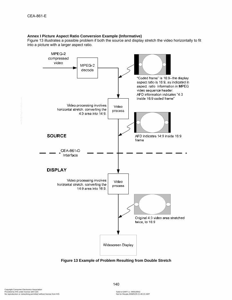
CEA-861-E
140
Annex I Picture Aspect Ratio Conversion Example (Informative) Figure 13 illustrates a possible problem if both the source and display stretch the video horizontally to fit into a picture with a larger aspect ratio.
Figure 13 Example of Problem Resulting from Double Stretch
Copyright Consumer Electronics Association Provided by IHS under license with CEA Sold to:GARY LI, W0519542
Not for Resale,2008/5/29 21:49:15 GMTNo reproduction or networking permitted without license from IHS
--``````,``,`,```,``,-`-`,,`,,`,`,,`---

CEA-861-E
141
Annex J [ Intentionally Omitted ]
Copyright Consumer Electronics Association Provided by IHS under license with CEA Sold to:GARY LI, W0519542
Not for Resale,2008/5/29 21:49:15 GMTNo reproduction or networking permitted without license from IHS
--``````,``,`,```,``,-`-`,,`,,`,`,,`---

CEA-861-E
142
Annex K Audio Speaker Placement & Channel Allocation Compatibility (Informative) CEA-861-E does not exactly follow professional broadcast/production industry (i.e. MPGA, ITU, or SMPTE) speaker placement and audio channel allocation standards. Table 102 compares the speaker placements between the SMPTE 320M [42] and CEA-861-E standards. There is general agreement between 5.1 channels – although the exact audio channel descriptions and abbreviations are slightly different. All other channels have no direct equivalents.
SMPTE 320M [42] CEA-861 Audio channel Abbreviation Abbreviation Audio Channel
Left L FL Front Left Center C FC Front Center Right R FR Front Right
Left surround LS RL Rear Left Right surround RS RR Rear Right
Low-frequency effects LFE LFE Low Frequency Effect Mono surround MS
Mono surround at a --3 dB level MS (-3dB) Left total Lt
Right total Rt Stereo left Lo
Stereo right Ro Monophonic M Freely usable F
Unassigned / unused U FLC Front Left Center FLW Front Left Wide FLH Front Left High FRC Front Right Center FRW Front Right Wide FRH Front Right High FCH Front Center High RC Rear Center RLC Rear Left Center RRC Rear Right Center TC Top Center
Table 102 SMPTE/CEA Audio Channel Description & Abbreviation Comparison
Copyright Consumer Electronics Association Provided by IHS under license with CEA Sold to:GARY LI, W0519542
Not for Resale,2008/5/29 21:49:15 GMTNo reproduction or networking permitted without license from IHS
--``````,``,`,```,``,-`-`,,`,,`,`,,`---

CEA-861-E
143
Table 103 compares the channel assignments between SMPTE 320M [42] and CEA-861-E standards. Here again, there is general agreement between the 5.1 channels except for the FC and LFE channels, which are swapped.
Channel SMPTE 320M CEA-861
1 L FL 2 R FR 3 C LFE 4 LFE FC 5 LS RL or RC 6 RS RR 7 Lt or Lo RC, RLC, FLC, FCH, FLH, or FLW 8 Rt or Ro RRC, FRC, TC, FRH, FRW, or FCH
Table 103 SMPTE/CEA Audio Channel Assignment Comparison
Copyright Consumer Electronics Association Provided by IHS under license with CEA Sold to:GARY LI, W0519542
Not for Resale,2008/5/29 21:49:15 GMTNo reproduction or networking permitted without license from IHS
--``````,``,`,```,``,-`-`,,`,,`,`,,`---

CEA-861-E
144
Annex L Video Timing Examples (Informative) This section gives three examples showing how tabular data from Table 2 and Table 3 is applied to the generalized waveforms of Figure 1, Figure 2, and Figure 5 for selected video timings. In these examples, all variables are replaced by specific values either taken directly from the tables or calculated using table values. Values for all of the line numbering variables are given in the table attached to the lower-left of each figure. These values also replace the respective variables in the figure.
Figure 14 General Progressive Example for Video ID Codes 2 & 3 (720x480p @ 60 Hz)
Copyright Consumer Electronics Association Provided by IHS under license with CEA Sold to:GARY LI, W0519542
Not for Resale,2008/5/29 21:49:15 GMTNo reproduction or networking permitted without license from IHS
--``````,``,`,```,``,-`-`,,`,,`,`,,`---
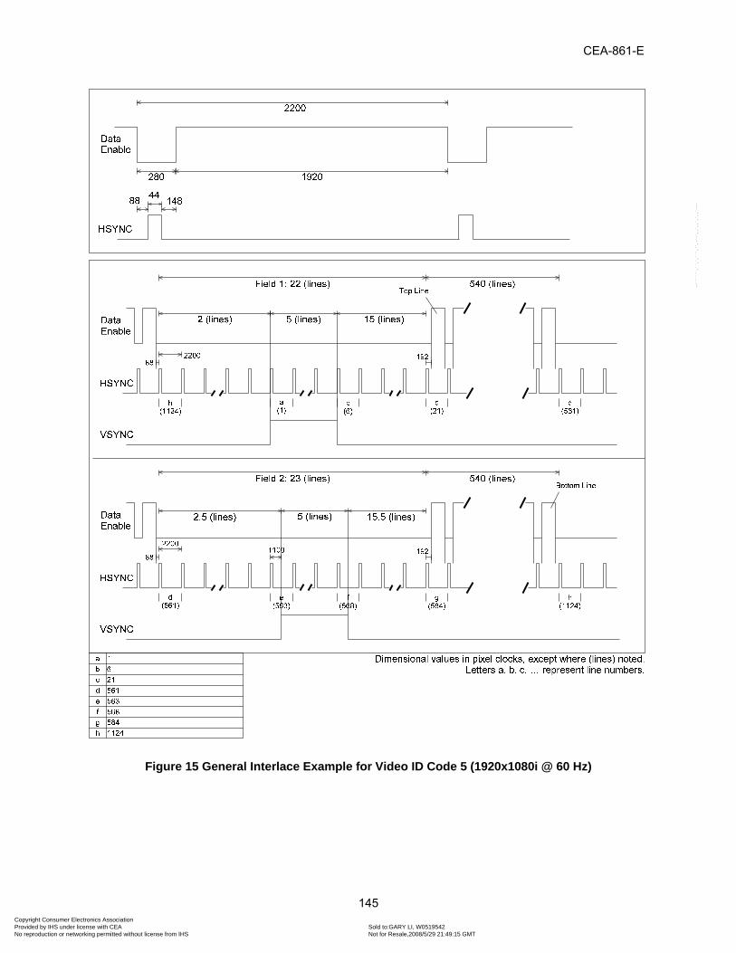
CEA-861-E
145
Figure 15 General Interlace Example for Video ID Code 5 (1920x1080i @ 60 Hz)
Copyright Consumer Electronics Association Provided by IHS under license with CEA Sold to:GARY LI, W0519542
Not for Resale,2008/5/29 21:49:15 GMTNo reproduction or networking permitted without license from IHS
--``````,``,`,```,``,-`-`,,`,,`,`,,`---

CEA-861-E
146
Figure 16 Special Interlace Example for Video ID Code 39 (1920x1080i-1250 Vtotal @ 50 Hz)
Copyright Consumer Electronics Association Provided by IHS under license with CEA Sold to:GARY LI, W0519542
Not for Resale,2008/5/29 21:49:15 GMTNo reproduction or networking permitted without license from IHS
--``````,``,`,```,``,-`-`,,`,,`,`,,`---

CEA Document Improvement Proposal
If in the review or use of this document, a potential change is made evident for safety, health or technical reasons, please email your reason/rationale for the recommended change to [email protected].
Consumer Electronics Association
Technology & Standards Department 1919 S Eads Street, Arlington, VA 22202 FAX: (703) 907-7693 [email protected]
Copyright Consumer Electronics Association Provided by IHS under license with CEA Sold to:GARY LI, W0519542
Not for Resale,2008/5/29 21:49:15 GMTNo reproduction or networking permitted without license from IHS
--``````,``,`,```,``,-`-`,,`,,`,`,,`---

Copyright Consumer Electronics Association Provided by IHS under license with CEA Sold to:GARY LI, W0519542
Not for Resale,2008/5/29 21:49:15 GMTNo reproduction or networking permitted without license from IHS
--``````,``,`,```,``,-`-`,,`,,`,`,,`---