CE2638NR BWT DE68 02325A - Hobbielektronika.hu
23
SERVICE MICROWAVE OVEN CONTENTS MICROWAVE OVEN 1. Precaution 2. Specifications 3. Operating Instructions 4. Disassembly and Reassembly 5. Alignment and Adjustments 6. Troubleshooting 7. Exploded Views and Parts List 8. PCB Diagrams 9. Schematic Diagrams Manual CE2638NR SRSC
Transcript of CE2638NR BWT DE68 02325A - Hobbielektronika.hu

SERVICEMICROWAVE OVEN CONTENTS
MICROWAVE OVEN
1. Precaution
2. Specifications
3. Operating Instructions
4. Disassembly and Reassembly
5. Alignment and Adjustments
6. Troubleshooting
7. Exploded Views and Parts List
8. PCB Diagrams
9. Schematic Diagrams
Manual
CE2638NR
SRSC

PRECAUTIONS TO BE OBSERVED BEFORE ANDDURING SERVICING TO AVOID POSSIBLEEXPOSURE TO EXCESSIVE MICROWAVE ENERGY(a) Do not operate or allow the oven to be
operated with the door open.(b) Make the following safety checks on
all ovens to be serviced before activatingthe magnetron or other microwavesource, and make repairs as necessary:(1) Interlock operation,(2) proper door closing,(3) seal and sealing surfaces (arcing,
wear, and other damage),(4) damage to or loosening of hinges
and latches,(5) evidence of dropping or abuse.
(c) Before turning on microwave powerfor any service test or inspection withinthe microwave generatingcompartments, check the magnetron,wave guide or transmission line, andcavity for proper alignment, integrity,and connections.
(d) Any defective or misadjustedcomponents in the interlock, monitor,door seal, and microwave generationand transmission systems shall berepaired, replaced, or adjusted byprocedures described in this manualbefore the oven is released to theowner.
(e) A Microwave leakage check to verifycompliance with the Federalperformance standard should beperformed on each oven prior torelease to the owner.

- 1 -
1. PrecautionFollow these special safety precautions. Although the microwave oven is completely safe during ordinary use,repair work can be extremely hazardous due to possible exposure to microwave radiation, as well as potentiallylethal high voltages and currents.
1-1 Safety precautions ( )
1. All repairs should be done in accordancewith the procedures described in thismanual. This product complies withFederal Performance Standard 21 CFRSubchapter J(DHHS).
2. Microwave emission check should beperformed to prior to servicing if the oven isoperative.
3. If the oven operates with the door open :Instruct the user not to operate the oven andcontact the manufacturer and the center fordevices and radiological health immediately.
4. Notify the Central Service Center if themicrowave leakage exceeds 5 mW/cm2.
5. Check all grounds.
6. Do not power the MWO from a "2-prong"AC cord. Be sure that all of the built-inprotective devices are replaced. Restore anymissing protective shields.
7. When reinstalling the chassis and itsassemblies, be sure to restore all protectivedevices, including: nonmetallic controlknobs and compartment covers.
8. Make sure that there are no cabinet openingsthrough which people --particularlychildren --might insert objects and contactdangerous voltages. Examples: Lamp hole,ventilation slots.
9. Inform the manufacturer of any oven foundto have emission in excess of 5 mW/cm2 ,Make repairs to bring the unit intocompliance at no cost to owner and try todetermine cause.
Instruct owner not to use oven until it hasbeen brought into compliance.
CENTRAL SERVICE CENTER
10. Service technicians should remove theirwatches while repairing an MWO.
11. To avoid any possible radiation hazard,replace parts in accordance with the wiringdiagram. Also, use only the exactreplacements for the following parts:Primary and secondary interlock switches,interlock monitor switch.
12. If the fuse is blown by the Interlock MonitorSwitch: Replace all of the following at thesame time: Primary, door sensing switchand power relay, as well as the InterlockMonitor Switch. The correct adjustment ofthese switches is described elsewhere inthis manual. Make sure that the fuse has thecorrect rating for the particular model beingrepaired.
13. Design Alteration Warning:Use exact replacement parts only, i.e.,only those that are specified in thedrawings and parts lists of this manual.This is especially important for theInterlock switches, described above.Never alter or add to the mechanical orelectrical design of the MWO. Any designchanges or additions will void themanufacturer's warranty. Always unplugthe unit's AC power cord from the ACpower source before attempting toremove or reinstall any component orassembly.
14. Never defeat any of the B+ voltageinterlocks. Do not apply AC power to theunit (or any of its assemblies) unless allsolid-state heat sinks are correctly installed.
15. Some semiconductor ("solid state") devicesare easily damaged by static electricity.Such components are calledElectrostatically Sensitive Devices (ESDs).Examples include integrated circuits andfield -effect transistors.Immediately before handling anysemiconductor components or assemblies,drain the electrostatic charge from yourbody by touching a known earth ground.
16. Always connect a test instrument's groundlead to the instrument chassis ground beforeconnecting the positive lead; always removethe instrument's ground lead last.

- 2 -
H. V. Diode
Short
H. V. Capacitor
1-2 Special Servicing Precautions (Continued)
17. When checking the continuity of the witchesor transformer, always make sure that thepower is OFF, and one of the lead wires isdisconnected.
18. Components that are critical for safety areindicated in the circuit diagram byshading, or .
19. Use replacement components that have thesame ratings, especially for flame resistanceand dielectric strength specifications. Areplacement part that does not have thesame safety characteristics as the originalmight create shock, fire or other hazards.
1-3 Special High Voltage Precautions
1. High Voltage WarningDo not attempt to measure any of the highvoltages --this includes the filament voltageof the magnetron. High voltage is presentduring any cook cycle.Before touching any components or wiring,always unplug the oven and discharge thehigh voltage capacitor (See Figure 1-1)
2. The high-voltage capacitor remains chargedabout 30 seconds after disconnection. Shortthe negative terminal of the high-voltagecapacitor to to the oven chassis. (Use ascrewdriver.)
3. High voltage is maintained within specifiedlimits by close-tolerance, safety-relatedcomponents and adjustments. If the highvoltage exceeds the specified limits, checkeach of the special components.
PRECAUTION
There exists HIGH VOLTAGE ELECTRICITYwith high current capabilities in the circuits of theHIGH VOLTAGE TRANSFORMER secondaryand filament terminals. It is extremely dangerousto work on or near these circuits with the ovenenergized.DO NOT measure the voltage in the high voltagecircuit including filament voltage of magnetron.
PRECAUTIONNever touch any circuit wiring with your handnor with uninsulated tool during operation.
PRECAUTIONServicemen should remove their watcheswhenever working close to or replacing themagnetron.
Fig. 1-1 Discharging High Voltage Capacitor
Touch chassis ground first then short to the highvoltage capacitor terminal by using screwdriver orjumper wire.

- 3 -
2. Specifications
2-1 Table of Specifications
TIMER
POWER SOURCE
POWER CONSUMPTION
OUTPUT POWER
OPERATING FREQUENCY
MAGNETRON
COOLING METHOD
OUTSIDE DIMENSIONS
OVEN DIMENSIONS
OVEN SHIPPING DIMENSIONS
SHIPPING WEIGHT APPROX.
99 MINUTES 90 SECONDS
230V 50Hz, AC
MICROWAVE : 1,200W
GRILL : 1100W
FROM 100 TO 750W
(IEC-705 TEST PROCEDURE)
2,450MHz
OM75PH(31)ESS
COOLING FAN MOTOR
489(W) x 275(H) x 383(D)
306(W) x 181(H) x 320(D)
557(W) x 329(H) x 403(D)
NET 14.5kg
GROSS 16.0kg

- 4 -
489mm
342mm
275m
m
206mm
383mm
VENTILATION HOLES
GRILL
LIGHTDISPLAY
COUPLER
DOORDOOR LATCHES
OPEN DOORPUSH BUTTON
METAL RACK
SAFETYINTERLOCK HOLES
ROLLER RING
CONTROL PANEL
TURNTABLE
3. Operating Instructions
3-1 Control Panel
3-2 Features & External Views

- 5 -
4. Disassembly and Reassembly
4-1 Replacement of Magnetron, Motor Assembly and Lamp
Remove the magnetron including the shield case, permanent magnet, choke coils and capacitors (all ofwhich are contained in one assembly).
1. Disconnect all lead wires from the magnetron and lamp.2. Remove a screw securing air cover.3. Remove the air cover.4. Remove screws securing the magnetron to the wave guide.5. Take out the magnetron very carefully.6. Remove nuts from the back panel.7. Take out the fan motor.8. Remove the oven lamp by rotating to pull out from hole of air cover.
NOTE1: When removing the magnetron, make sure that its antenna does not hit any adjacentparts, or it may be damaged.
NOTE2: When replacing the magnetron, be sure to remount the magnetron gasket in the correctposition and make sure the gasket is in good condition.
4-2 Replacement of High Voltage Transformer
1. Discharge the high voltage capacitor.2. Disconnect all the leads.3. Remove the mounting bolts.4. Reconnect the leads correctly and firmly.
PRECAUTIONServicemen should remove their watches wheneverworking close to or replacing the magnetron.
PRECAUTIONThere exists HIGH VOLTAGE ELECTRICITY with high current capabilities in the circuits of the HIGHVOLTAGE TRANSFORMER secondary and filament terminals. It is extremely dangerous to work on or nearthese circuits with the oven energized.DO NOT measure the voltage in the high voltage circuit including filament voltage of magnetron.

- 6 -
4-3 Replacement of Door Assembly4-3-1 Removal of Door Assembly
Remove hex bolts securing the upper hinge andlower hinge. Then remove the door assembly.
4-3-2 Removal of Door "C"
Insert flat screwdriver into the gap between Door"A" and Door "C" to remove Door "C". Be carefulwhen handling Door "C" because it is fragile.Then remove the door assembly.
4-3-3 Removal of Door "E"
Following the procedure as shown in the figure,insert and bend a thin metal plate between Door"E" and Door "A" until you hear the 'tick' sound.
1. Insertion depth of the thin metal plate should be0.5mm or less.
4-3-4 Removal of Key Door & Spring
Remove pin hinge from Door "E"Detach spring from Door "E" and key door.
Door "E"
Key Door Spring
Door "E"
SCREWS
Upper Hinge
Lower HingeSCREW

- 7 -
4-3-5 Reassembly Test
1. When mounting the door to the oven, be sure to adjust the door parallel to the bottom line of the ovenface plate by moving the upper hinge and lower hinge in the direction necessary for proper alignment.
2. Adjust so that the door has no play between the inner door surface and oven front surface. If the doorassembly is not mounted properly, microwave energy may leak from the space between the door and oven.
3. Do the microwave leakage test.
4-4 Replacement of Fuse
1. Disconnect the oven from the power source.2. When 10A fuse blows out by the operation of interlock monitor switch failure, replace the primary interlock
switch, door sensing switch, monitor switch and power relay.3. When the above three switches operate properly, check if any other part such as the control circuit board,
blower motor or high voltage transformer is defective.
4-5 Replacement of Drive Motor
1. Take out the glass tray, guide roller and couplerfrom cavity.
2. Turn the oven upside down to replace the drive motor.3. Remove a screw securing the drive motor cover.4. Disconnect all the lead wires from the drive motor.5. Remove screws securing the drive motor to the cavity.6. Remove the drive motor.7. When replacing the drive motor, be sure to
remount it in the correct position.8. Connect all the leads to the drive motor.9. Screw the drive motor cover to the base plate
with a screw driver.10. Remount the coupler in the correct position.
After replacement of the defective component parts of the door, reassemble it and follow the instructionsbelow for proper installation and adjustment so as to prevent an excessive microwave leakage.
Drive Motor Cover Base Plate
Drive Motor

- 8 -
4-6 Replacement of Control Circuit Board
4-6-1 Removal of Control Box
1. Be sure to ground any static electric charge inyour body and never touch the control circuit.
2. Disconnect the connectors from the controlcircuit board.
3. Remove screws securing the control boxassembly.
4. Remove the screw securing the ground tail ofthe keyboard.
4-6-2 Removal of P.C.B Assembly
1. Pull the lever end of the plastic fastener andremove the Flexible Printed Circuit(FPC) ofmembrane panel.
2. Remove screws securing the control circuitboard.
3. Lift up the control circuit board from the Ass'ycontrol box.
4. When reconnecting the FPC connector, makesure that the holes on the connector are properlyengaged with the hooks on the Plastic Fastener.
4-6-3 Removal of Window Display & Membrane Panel
1. Window display should not be disassembled asits mounting tabs will be broken. If repair workis difficult, replace with Ass'y control panel.
2. The membrane key board is attached to theescutcheon base with double faced adhesivetape. Therefore, applying hot air such as using ofhair dryer is recommended for smootherremoval.
3. When installing new membrane key board, makesure that the surface of escutcheon base iscleaned sufficiently so that any problems(shorted contacts or uneven surface) can beavoided.
SCREWS
ASSY PCB
Control box
Screw
Membrane panel

- 9 -
5. Alignment and Adjustments
5-1 High Voltage Transformer
1. Remove connectors from the transformer terminalsand check continuity.
2. Normal resistance readings are as follows:
(Room temperature = 20°C)
5-2 Low Voltage Transformer
1. The low voltage transformer is located on thecontrol circuit board.
2. Remove the low voltage transformer from thePCB Ass'y and check continuity.
3. Normal resistor reading is shown in the table.
5-3 Magnetron
1. Continuity checks can indicate only an openfilament or a shorted magnetron. To diagnose anopen filament or shorted magnetron :
2. Isolate the magnetron from the circuit bydisconnecting its leads.
3. A continuity check across the magnetron filamentterminals should indicate one ohm or less.
4. A continuity check between each filament terminaland magnetron case should read open.
PrimaryTerminals
Filament Terminals
SecondaryTerminal
Magnetron Antenna Gasket Plate
Cooling Fins
PRECAUTION1. High voltage is present at the high voltage terminals during any cook cycle.2. It is neither necessary nor advisable to attempt measurement of the high voltage.
3. Before touching any oven components or wiring, always unplug the oven from its power source anddischarge the high voltage capacitor.
Secondary
Filament
Primary
Approx. 139Ω
Approx. 0Ω
Approx. 1.94Ω
Terminals Resistance
1~2(Input)
3~4(Output7V)
5~6(Output17V)
1,201Ω
4.348Ω
21.72Ω

- 10 -
5-4 High Voltage Capacitor1. Check continuity of the capacitor with the meter set at the highest resistance scale.2. Once the capacitor is charged, a normal capacitor shows continuity for a short time, and then indicates 9MΩ.3. A shorted capacitor will show continuous continuity.4. An open capacitor will show constant 9MΩ.5. Resistance between each terminal and chassis should read infinite.
5-5 High Voltage Diode
1. Isolate the diode from the circuit by disconnecting its leads.2. With the ohm-meter set at the highest resistance scale, measure across the diode terminals. Reverse the
meter leads and read the resistance. A meter with 6V, 9V or higher voltage batteries should be used tocheck the front-to back resistance of the diode (otherwise an infinite resistance may be read in bothdirections). The resistance of a normal diode will be infinite in one direction and several hundred KΩ in theother direction.
5-6 Main Relay and Power Control Relay
1. The relays are located on the PCB Ass'y. Isolate them from the main circuit by disconnecting the leads.2. Operate the microwave oven with a water load in the oven. Set the power level set to high.3. Check continuity between terminals of the relays after the start pad is pressed.
5-7 Adjustment of Primary Switch, Door Sensing Switch and Monitor Switch
1. When mounting Primary switch and InterlockMonitor switch to Latch Body, consult the figure.
2. No specific adjustment during installation ofPrimary switch and Monitor switch to the latchbody is necessary.
3. When mounting the Latch Body to the ovenassembly, adjust the Latch Body by moving it sothat the oven door will not have any play in it.Check for play in the door by pulling the doorassembly. Make sure that the latch keys movesmoothly after adjustment is completed.Completely tighten the screws holding the LatchBody to the oven assembly.
4. Reconnect to Monitor switch and check thecontinuity of the monitor circuit and all latchswitches again by following the components testprocedures.
5. Confirm that the gap between the switchhousing and the switch actuator is no more than0.5mm when door is closed.
6. Interlock Switch Replacement - Whenreplacing faulty switches, be sure switch mountingtabs are not bent, broken or otherwise deficient intheir ability to secure the switches in place.
Door Open Door Closed
Primary switch Monitor
switch (COM-NC) Monitor
switch (COM-NO) Door
Sensing S/W
∞0
∞∞
0
∞0
0
Primary InterlockSwitch
InterlockMonitorSwitch
Body Latch
Lever Door(B)
Door SensingSwitch
PrecautionFor continued protection against radiation hazard, replace parts in accordance with the wiring diagram and be sure touse the correct part number for the following switches: Primary and secondary interlock switches, and the interlockmonitor switch (replace all together). Then follow the adjustment procedures below. After repair and adjustment, besure to check the continuity of all interlock switches and the interlock monitor switch.

- 11 -
5-8 Output Power of Magnetron
The output power of the magnetron can be measured by performing a water temperature rise test.Equipment needed :* Two 1-liter cylindrical borosilicate glass vessel (Outside diameter 190 mm)* One glass thermometer with mercury columnNOTE: Check line voltage under load. Low voltage will lower the magnetron output. Make all temperature
and time tests with accurate equipment.1. Fill the one liter glass vessel with water.2. Stir water in glass vessel with thermometer, and record glass vessel's temperature ("T1", 10±1°C).3. After moving the water into another glass vessel, place it in the center of the cooking tray. Set the oven to
high power and operate for 55seconds exactly. (3 seconds included as a holding time of magnetronoscillation:)
4. When heating is finished, stir the water again with the thermometer and measure the temperature ("T2").5. Subtract T1 from T2. This will give you the water temperature rise. (T)6. The output power is obtained by the following formula;
Output Power = 4.187 x 1000 x T+0.55xMcx(T2 -T0) 55 : Heating Time (sec)52 52 : Counting Time (sec)
4.187 : Coefficient for Water1000 : Water (cc)T : Temperature Rise (T2-T1)To : Room TemperatureMc : Cylindrical borosilicate glass weight
7. Normal temperature rise for this model is 9°C to 11°C at 'HIGH'.NOTE 1: Variations or errors in the test procedure will cause a variance in the temperature rise.Additional power test should be made if temperature rise is marginal.NOTE 2: Output power in watts is computed by multiplying the temperature rise (step 5) by a factor of 91times the of centigrade temperature.
5-9 Microwave Heat Distribution - Heat Evenness
The microwave heat distribution can be checked indirectly by measuring the water temperature rise atcertain positions in the oven:1. Prepare five beakers made of 'Pyrex', having 100 milliliters capacity each.2. Measure exactly 100milliliters off water load with a measuring cylinder, and pour into each beaker.3. Measure the temperature of each water load. (Readings shall be taken to the first place of decimals.)4. Put each beaker in place on the cooking tray as illustrated in figure below. Start heating.5. After heating for 2 minutes, measure the water temperature in each beaker.6. Microwave heat distribution rate can be calculated as follows:
MinimumHeat Distribution = Temperature Rise X 100(%)
MaximumTemperature Rise
The result should exceed 65%.
CAUTIONMICROWAVE RADIATION
PERSONNEL SHOULD NOT ALLOW EXPOSURE TO MICROWAVE RADIATION FROM MICROWAVEGENERATOR OR OTHER PARTS CONDUCTING MICROWAVE ENERGY.
D
D
D/4
D/4
D/4D/4
Cooking Tray
BeakeD
D
D/4
D/4
D/4D/4
Cooking Tray
BeakeD
D
D/4
D/4
D/4D/4
Cooking Tray
BeakeD
D
D/4
D/4
D/4D/4
Cooking Tray
BeakeD
D
D/4
D/4
D/4D/4
Cooking Tray
BeakeD
D
D/4
D/4
D/4D/4
Cooking Tray
BeakeD
D
D/4
D/4
D/4D/4
Cooking Tray
BeakeD
D
D/4
D/4
D/4D/4
Cooking Tray
Beake

- 12 -
5-10 Procedure for Measurement of Microwave Energy Leakage
1) Pour 275±15cc of 20±5°C(68±9°F) water in a beakerwhich is graduated to 600cc, and place the beaker inthe center of the oven.
2) Start to operate the oven and measure the leakage byusing a microwave energy survey meter.
3) Set survey meter with dual ranges to 2,450MHz.4) When measuring the leakage, always use the 2 inch
spacer cone with the probe. Hold the probeperpendicular to the cabinet door. Place the spacercone of the probe on the door and/or cabinet doorseam and move along the seam, the door viewingwindow and the exhaust openings moving theprobe in a clockwise direction at a rate of 1 inch/sec. If the leakage testing of the cabinet door seam istaken near a corner of the door, keep the probe perpendicular to the areas making sure that the probe endat the base of the cone does not get closer than 5cm to any metal. If it gets closer than 5cm, erroneousreadings may result.
5) Measured leakage must be less than 4mW/cm2 , after repair or adjustment.
5-11 Check for Microwave Leakage
1. Remove the outer panel.2. Pour 275±15cc of 20±5°C(68±9°F) water in a beaker
which is graduated to 600cc, and place the beaker inthe center of the oven.
3. Start the oven at the highest power level.4. Set survey meter dual ranges to 2,450MHz.5. Using the survey meter and spacer cone as described
above, measure near the opening of magnetron, thesurface of the air guide and the surface of the waveguide as shown in the following photo.( but avoid thehigh voltage components.) The reading should be less than 4mW/cm2 .
5-12 Note on Measurement
1) Do not exceed the limited scale.2) The test probe must be held on the grip of the handle, otherwise a false reading may result when the
operator's hand is between the handle and the probe.3) When high leakage is suspected, do not move the probe horizontally along the oven surface; this may
cause damage to the probe.4) Follow the recommendation of the manufacturer of the microwave energy survey meter.
5-13 Leakage Measuring Procedure
5-13-1 Record keeping and notification after measurement1) After adjustment and repair of a radiation preventing device, make a repair record for the measured
values, and keep the data.2) If the radiation leakage is more than 4 mW/cm2 after determining that all parts are in good condition,
functioning properly and the identical parts are replaced as listed in this manual notify that fact to ;
CENTRAL SERVICE CENTER
5-13-2 At least once a year have the microwave energy survey meter checked for accuracy by itsmanufacturer.
Maximum allowable leakage is 5mW/cm2.4mW/cm2 is used to allow for measurement and meter accuracy

- 13 -
6. Troubleshooting
6-1 Electrical Malfunction
SYMPTOM CAUSE CORRECTIONS
Oven is dead.Fuse is OK.No display and no operation at all .
1. Open or loose lead wire harness2. Open thermal cutout (Magnetron)3. Open low voltage transformer4. Defective Ass'y PCB
Check fan motor when thermalcutout is defective.Check Ass'y PCB when L.V.Tis defective.
No display and no operation at all.Fuse is blown.
1. Shorted lead wire harness2. Defective primary latch switch
(NOTE 1)3. Defective monitor switch (NOTE1)4. Shorted H.V.Capacitor5. Shorted H.V.Transformer (NOTE2)
Check adjustment of primary,interlock monitor,power relay, door sensingswitch.
NOTE 1: All of these switches must be replaced at the same time.(refer to adjustment instructions)Check continuity of power relay contacts and if it hascontinuity, replace power relay also.
NOTE 2: When H.V.Transformer is replaced, check diode andmagnetron also.
Oven does not acceptkey input (Program)
1. Key input is not in-Sequence2. Open or loose connection of
membrane key pad to Ass'y PCB3. Shorted or open membrane panel4. Defective Ass'y PCB
Refer to operation procedure.
Replace PCB main.
Timer starts countdown but nomicrowave oscillation.(No heat while oven lamp and fanmotor turn on.)
1. Off-alignment of latch switches2. Open or loose connection of high
voltage circuit especiallymagnetron filament circuit
NOTE: Large contact resistance willbring lower magnetronfilament voltage and causemagnetron to lower outputand/or intermittent oscillation.
3. Defective high voltagecomponents H.V.Transformer H.V.Capacitor H.V.Diode, H.V.FuseMagnetron
4. Open or loose wiring of power relay5. Defective primary latch switch6. Defective power relay or Ass'y PCB
Adjust door and latch switches.
Check high voltage componentaccording tocomponent test procedure andreplace if it isdefective.
Replace PCB main.
PRECAUTION1. CHECK GROUNDING BEFORE CHECKING FOR TROUBLE.2. BE CAREFUL OF THE HIGH VOLTAGE CIRCUIT.3. DISCHARGE THE HIGH VOLTAGE CAPACITOR.4. WHEN CHECKING THE CONTINUITY OF THE SWITCHES OR TRANSFORMER, DISCONNECT
ONE LEAD WIRE FROM THESE PARTS AND THEN CHECK CONTINUITY WITHOUT THEPOWER SOURCE ON. TO DO OTHERWISE MAY RESULT IN A FALSE READING OR DAMAGETO YOUR METER.
5. DO NOT TOUCH ANY PART OF THE CIRCUIT OR THE CONTROL CIRCUIT BOARD, SINCESTATIC DISCHARGE MAY DAMAGE IT.ALWAYS TOUCH GROUND WHILE WORKING ON IT TO DISCHARGE ANY STATIC CHARGE
BUILT UP.
- 14 -
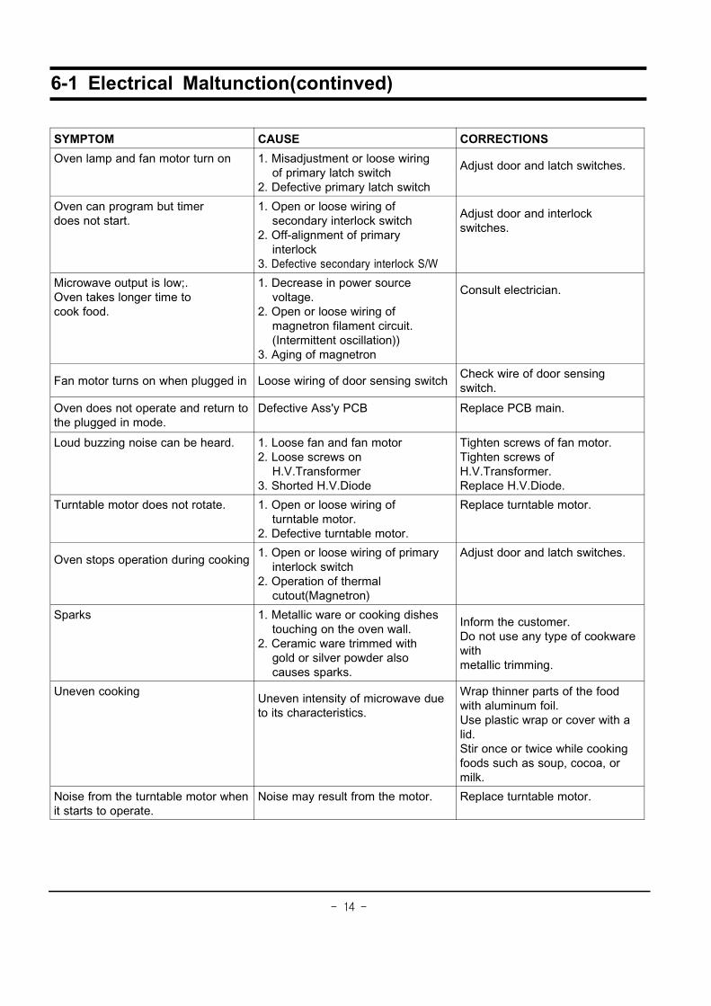
6-1 Electrical Maltunction(continved)
SYMPTOM CAUSE CORRECTIONS
Oven lamp and fan motor turn on 1. Misadjustment or loose wiringof primary latch switch
2. Defective primary latch switch
Adjust door and latch switches.
Oven can program but timerdoes not start.
1. Open or loose wiring ofsecondary interlock switch
2. Off-alignment of primaryinterlock
3. Defective secondary interlock S/W
Adjust door and interlockswitches.
Microwave output is low;.Oven takes longer time tocook food.
1. Decrease in power sourcevoltage.
2. Open or loose wiring ofmagnetron filament circuit.(Intermittent oscillation))
3. Aging of magnetron
Consult electrician.
Fan motor turns on when plugged in Loose wiring of door sensing switchCheck wire of door sensingswitch.
Oven does not operate and return tothe plugged in mode.
Defective Ass'y PCB Replace PCB main.
Loud buzzing noise can be heard. 1. Loose fan and fan motor2. Loose screws on
H.V.Transformer3. Shorted H.V.Diode
Tighten screws of fan motor.Tighten screws ofH.V.Transformer.Replace H.V.Diode.
Turntable motor does not rotate. 1. Open or loose wiring ofturntable motor.
2. Defective turntable motor.
Replace turntable motor.
Oven stops operation during cooking1. Open or loose wiring of primary
interlock switch2. Operation of thermal
cutout(Magnetron)
Adjust door and latch switches.
Sparks 1. Metallic ware or cooking dishestouching on the oven wall.
2. Ceramic ware trimmed withgold or silver powder alsocauses sparks.
Inform the customer.Do not use any type of cookwarewithmetallic trimming.
Uneven cookingUneven intensity of microwave dueto its characteristics.
Wrap thinner parts of the foodwith aluminum foil.Use plastic wrap or cover with alid.Stir once or twice while cookingfoods such as soup, cocoa, ormilk.
Noise from the turntable motor whenit starts to operate.
Noise may result from the motor. Replace turntable motor.

- 15 -
7. Exploded Views and Parts List
7-1 Exploded Views
MM01
MM63
MM62
MM22
MM16
MM29 MM30
MM31
MM67
MM06
MM172
MM26
MM17
MM08
MM09
MM07MM59
MM18
MM19
MM20
MM64
MM03
MM32
MM10
MM13
MM171
MM05
MM55
MM14
MM27
MM28
MB01
MB05
MB03
MB04MB08
MB02
MD01
MD08
MD04
MD09MD02
MD03
MD10
MD07
MC06
MC05
MM61
MM68
MM60
MM25
MC01
MC05
MC04MC02
MC03
MC07
MC13
MC06
MM88

- 16 -
7-2 Main Parts List
No. Code No. Description Specification Q'ty Remark
MB01 DE96-00115C ASSY BODY LATCH CE2611N,NC2000(BUTTON) 1
MB02 3405-000175 SWITCH-MICRO 250V,15A,200gf,SPST-NO 1
MB03 3405-000178 SWITCH-MICRO 250V,15A,200gf,SPST-NO 1 PRI
MB04 DE66-00088A LEVER-SWITCH NC2000(0.6/0.8/1.2),PP,NTR,BUTTON-TYPE 1
MB05 DE72-00138A BODY-LATCH NC2000(0.6/0.8/1.2),PP,-,-,-,-,WHT,- 1
MB08 3405-000178 SWITCH-MICRO 250V,15A,200gf,SPST-NO 1 SEC
MM01 DE70-00184P PANEL-OUTER MW850WA,C/STEEL,T0.5,P/WHT,NC2-0.8CU.FT 1
MM03 DE39-00162B WIRE HARNESS-A CE2727N,-,230V50HZ,-,-,-,-,NC2000 1
MM05 DE96-00010A ASSY NOISE FILTER SN-3WED,250V10A,3W NO-INRUSH TC,-,-,-,- 1
MM06 DE96-00031A ASSY-MOTOR FAN SMF-3RDEA,230V50HZ,2400RPM,M1733,-,-,- 1
MM07 DE39-20058C ASSY POWER CORD KKP-4819D/B232,250V16A,L1700,G 1
MM08 OM75PH(31)ESS ASSY-MAGNETRON OM75PH(31)ESS 1
MM09 DE71-60457B COVER-AIR 3RD-0.7(BTM),PP,-,-,-,-,-,- 1
MM10 4713-001031 LAMP-INCANDESCENT 230V,173mA,40W,ORG,-,-,25x69mm 1 CV/AIR
MM13 DE66-90113A LEVER-DOOR PP(TB53-GH41),T2.5,-,-,12g,NTR,3RD-W,- 1
MM14 DE26-00059A TRANS-H.V SHV-E1713A,230V,50HZ,2130V/3.65V,-,-,-,- 1
MM16 DE71-00159A COVER-CEILING CN2835,MICA SHEET,T0.3,W114,L56,-,-,NC0.8cu.ft 1
MM17 DE47-20009A THERMOSTAT PW2N-520PB,160/60,250V/7.5A,H, 1 MG-TCO
MM171 DE47-00002B THERMOSTAT PW2N,-,-,100,110,-,-,-,187H,30.0 1
MM172 DE47-20010A THERMOSTAT PW-2N(120/60)187Y,250V7.5A,120 1 CAV-TCO
MM18 DE74-20102B TRAY-COOKING GLASS,T5.0,M745,-,- 1
MM19 DE97-00193B ASSY-GUIDE ROLLER NC2000 0.6,T2*P1198(14PI),-,- 1
MM20 DE67-00140A COUPLER NC2000(0.6~0.8),PPS(ESS840),-,3G,BRN,NEW 1
MM22 DE31-10154A MOTOR-SYNCHRONOUS M2HJ49ZR02,ST-16,50/60HZ,- 1
MM25 DE65-20014A CABLE CLAMP -,-,-,NY-66,-,DA-6N 1 P-CORD
MM26 DE71-00148A COVER-BLOWER MW850WA,PP,T1.5,-,-,-,NTR,NC2000(0.8CUFT) 1
MM27 DE61-40066A FOOT -,PP,-,BLK,-,-,- 2
MM28 DE80-00023B BASE-PLATE CE2877N,SGCC1,T0.6,-,-,NC2000,0.8CUFT 1
MM29 2501-001016 C-OIL 950nF,2.1KV,BK,35x54x80,20mm 1
MM30 DE61-00139A BRACKET-HVC NC2000,SECC,T0.8,-,-,-,0.6/0.8/1.2CUFT 1
MM31 DE59-00002A DIODE-H.V ESJC13-12B,12KV,-,-,-,MWO ALL,- 1
MM32 DE91-70061C ASSY-H.V.FUSE THV060T-0700-H,5KV/0.70A,BLU 1
MM55 3601-000448 FUSE-CARTRIDGE 250V,10A,SLOW-BLOW,CERAMIC,6.35x31.8mm 1
MM59 DE71-60451A COVER-BACK 3RD-0.7,SECC,T0.5,W115,L332,-,-,- 1
MM60 DE63-00049A GASKET-HEATER CE2613N,BRASS,T1.0,W53,L15,-,-,- 1
MM61 DE47-00016A HEATER SHG-2638E,-,-,1100W(1080W),-,230V,-,-,-,FNG 1
MM62 DE61-70060A SPRING-PLATE -,SK-5,T0.5,T0.5,-,-,-,-,-,-,- 1
MM63 DE61-30008A SUPPORTER-HEATER -,ALUMINA,T12,CE745G,-,-,- 1
MM64 DE74-70071D RACK-WIRE MSWR10,PI3,0.7/NC2000,D230,H85,-,- 1
MM67 DE61-00143A BRACKET-UPPER MW850WA,SECC,T0.5,-,-,-,NC2000(0.8CUFT) 1
MM68 DE63-00048A GASKET-STOPPER CE2613N,SECC,T1.0,W53,L15 1
MM88 DE73-90027B FERRITE RU65(RU15*28.6*6.5),-,M2L(FE2O3+Ni+Zn),- 1
- 17 -
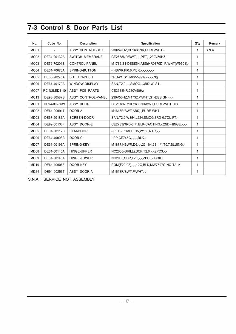
7-3 Control & Door Parts List
No. Code No. Description Specification Q'ty Remark
MC01 - ASSY CONTROL-BOX 230V49HZ,CE2638NR,PURE-WHT,- 1 S.N.A
MC02 DE34-00132A SWITCH MEMBRANE CE2638NR/BWT,-,-,PET,-,230V50HZ,- 1
MC03 DE72-70201B CONTROL-PANEL M1732,S1-DESIGN,ABS(HR0370D),P/WHT(W9501),- 1
MC04 DE61-70076A SPRING-BUTTON -,HSWR,PI0.6,PI0.6,-,-,-,-,-,-,- 1
MC05 DE66-20275A BUTTON-PUSH 3RD-W S1 MW5592W,-,-,-,-,9g 1
MC06 DE67-40179A WINDOW-DISPLAY SAN,T2.0,-,-,SMOG,-,3RD-W S1,- 1
MC07 RC-N2LED1-10 ASSY PCB PARTS CE2638NR,230V50Hz 1
MC13 DE93-30587B ASSY CONTROL-PANEL 230V50HZ,M1732,P/WHT,S1-DESIGN,-,-,- 1
MD01 DE94-00256W ASSY DOOR CE2618NR/CE2638NR/BWT,PURE-WHT,CIS 1
MD02 DE64-00091T DOOR-A M1618R/BWT,ABS,-,PURE-WHT 1
MD03 DE67-20186A SCREEN-DOOR SAN,T2.2,W354,L224,SMOG,3RD-0.7CU.FT,- 1
MD04 DE92-50133F ASSY DOOR-E CE2733(3RD-0.7),BLK-CAOTING,-,2ND-HINGE,-,-,- 1
MD05 DE01-00112B FILM-DOOR -,PET,-,L268,T0.15,W150,NTR,-,- 1
MD06 DE64-40008B DOOR-C -,PP,CE745G,-,-,-,BLK,- 1
MD07 DE61-00198A SPRING-KEY M1877,HSWR,D6,-,-,23 1/4,23 1/4,T0.7,BLUING,- 1
MD08 DE61-00145A HINGE-UPPER NC2000(GRILL),SCP,T2.0,-,-,ZPC3,-,- 1
MD09 DE61-00146A HINGE-LOWER NC2000,SCP,T2.0,-,-,ZPC3,-,GRILL 1
MD10 DE64-40006F DOOR-KEY POM(F20-02),-,-,12G,BLK,MW7897G,NO-TALK 1
MD24 DE94-00253T ASSY DOOR-A M1618R/BWT,P/WHT,-,- 1
S.N.A : SERVICE NOT ASSEMBLY

- 18 -
7-4 Standard Parts List
Code No. Description Specification Q'ty Remark
DE60-10012A SCREW-TAP TITE -,SWR10,M4,L10,TH,+,-,3,ZPC2,- 1 GRI-TCO
DE60-10012A SCREW-TAP TITE -,SWR10,M4,L10,TH,+,-,3,ZPC2,- 1 M/PANEL
DE60-10012A SCREW-TAP TITE -,SWR10,M4,L10,TH,+,-,3,ZPC2,- 1 P-CORD
DE60-10080B SCREW-WASHER -,2S,SWRCH18A,ZP2,PH,PI5,-,L10,-,- 4 HVT
DE60-10080B SCREW-WASHER -,2S,SWRCH18A,ZP2,PH,PI5,-,L10,-,- 4 MGT
DE60-10082H SCREW-A -,-,-,-,2S-4X12,TOOTHED,-,-,-,- 2 B-LATCH
DE60-10082H SCREW-A -,-,-,-,2S-4X12,TOOTHED,-,-,-,- 3 B-PLATE
DE60-10082H SCREW-A -,-,-,-,2S-4X12,TOOTHED,-,-,-,- 2 B-UPPER
DE60-10082H SCREW-A -,-,-,-,2S-4X12,TOOTHED,-,-,-,- 1 C-BLOWER
DE60-10082H SCREW-A -,-,-,-,2S-4X12,TOOTHED,-,-,-,- 1 CON-BOX
DE60-10082H SCREW-A -,-,-,-,2S-4X12,TOOTHED,-,-,-,- 1 COVER-AIR
DE60-10082H SCREW-A -,-,-,-,2S-4X12,TOOTHED,-,-,-,- 4 OUT-PANEL
DE60-10098A SCREW-ASSY TAP TITE -,GLD,SWRCH18A,ZPC2,PH,TC,-,M4X8,WT,- 1 CVT-TCO
DE60-10098A SCREW-ASSY TAP TITE -,GLD,SWRCH18A,ZPC2,PH,TC,-,M4X8,WT,- 1 D-MOTOR
DE60-10098A SCREW-ASSY TAP TITE -,GLD,SWRCH18A,ZPC2,PH,TC,-,M4X8,WT,- 2 MGT-TCO
DE60-10122A SCREW-TAP TH -,-,FE,FN,TAP,TH,-,2-4X8,-,- 1 P-OUTER
DE60-10195A SCREW-STAR POLE -,SWCH18A,4,12,TH,*,-,2,ZNC,- 2 C-BACK
DE60-20063A BOLT-FLANGE M4,10,ZPC3,YEL,MSWR,-,-,-,- 2 H/LOWER
DE60-20063A BOLT-FLANGE M4,10,ZPC3,YEL,MSWR,-,-,-,- 2 H/UPPER
DE60-30016A NUT-FLANGE M4,MSWR10,-,-,-,-,-,-,- 2 F-MOTOR
DE60-30016A NUT-FLANGE M4,MSWR10,-,-,-,-,-,-,- 2 HEATER
DE60-10088A SCREW-TAP PH -,-,FEFZY,PLAIN,PH,M3,-,L8,-,- 3 PCB
DE60-10012A SCREW-TAP TITE -,SWR10,M4,L10,TH,+,-,3,ZPC2,- 1 B/COVER
DE60-10098A SCREW-ASSY TAP TITE -,GLD,SWRCH18A,ZPC2,PH,TC,-,M4X8,WT,- 1 HVD
- 19
-
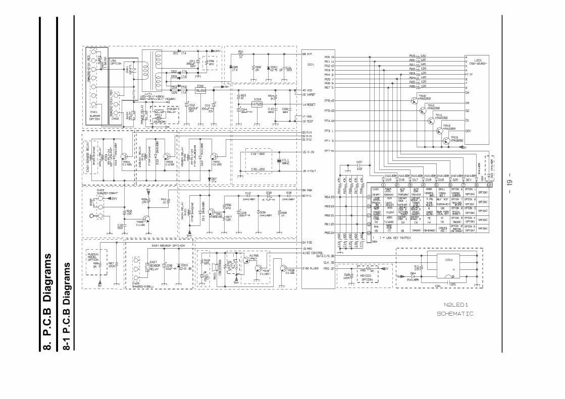
8.P
.C.B
Dia
gra
ms
8-1
P.C
.BD
iag
ram
s
- 20 -
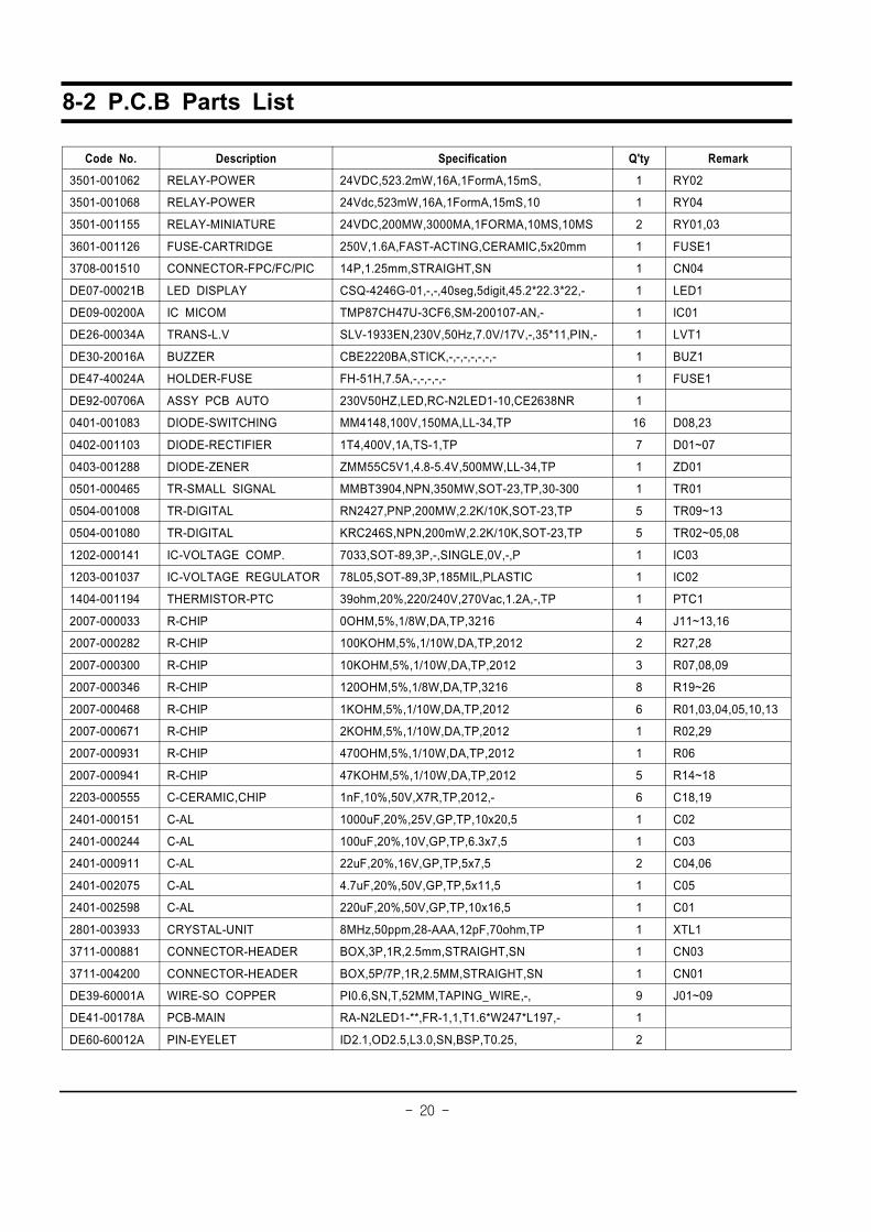
8-2 P.C.B Parts List
Code No. Description Specification Q'ty Remark
3501-001062 RELAY-POWER 24VDC,523.2mW,16A,1FormA,15mS, 1 RY02
3501-001068 RELAY-POWER 24Vdc,523mW,16A,1FormA,15mS,10 1 RY04
3501-001155 RELAY-MINIATURE 24VDC,200MW,3000MA,1FORMA,10MS,10MS 2 RY01,03
3601-001126 FUSE-CARTRIDGE 250V,1.6A,FAST-ACTING,CERAMIC,5x20mm 1 FUSE1
3708-001510 CONNECTOR-FPC/FC/PIC 14P,1.25mm,STRAIGHT,SN 1 CN04
DE07-00021B LED DISPLAY CSQ-4246G-01,-,-,40seg,5digit,45.2*22.3*22,- 1 LED1
DE09-00200A IC MICOM TMP87CH47U-3CF6,SM-200107-AN,- 1 IC01
DE26-00034A TRANS-L.V SLV-1933EN,230V,50Hz,7.0V/17V,-,35*11,PIN,- 1 LVT1
DE30-20016A BUZZER CBE2220BA,STICK,-,-,-,-,-,-,- 1 BUZ1
DE47-40024A HOLDER-FUSE FH-51H,7.5A,-,-,-,-,- 1 FUSE1
DE92-00706A ASSY PCB AUTO 230V50HZ,LED,RC-N2LED1-10,CE2638NR 1
0401-001083 DIODE-SWITCHING MM4148,100V,150MA,LL-34,TP 16 D08,23
0402-001103 DIODE-RECTIFIER 1T4,400V,1A,TS-1,TP 7 D01~07
0403-001288 DIODE-ZENER ZMM55C5V1,4.8-5.4V,500MW,LL-34,TP 1 ZD01
0501-000465 TR-SMALL SIGNAL MMBT3904,NPN,350MW,SOT-23,TP,30-300 1 TR01
0504-001008 TR-DIGITAL RN2427,PNP,200MW,2.2K/10K,SOT-23,TP 5 TR09~13
0504-001080 TR-DIGITAL KRC246S,NPN,200mW,2.2K/10K,SOT-23,TP 5 TR02~05,08
1202-000141 IC-VOLTAGE COMP. 7033,SOT-89,3P,-,SINGLE,0V,-,P 1 IC03
1203-001037 IC-VOLTAGE REGULATOR 78L05,SOT-89,3P,185MIL,PLASTIC 1 IC02
1404-001194 THERMISTOR-PTC 39ohm,20%,220/240V,270Vac,1.2A,-,TP 1 PTC1
2007-000033 R-CHIP 0OHM,5%,1/8W,DA,TP,3216 4 J11~13,16
2007-000282 R-CHIP 100KOHM,5%,1/10W,DA,TP,2012 2 R27,28
2007-000300 R-CHIP 10KOHM,5%,1/10W,DA,TP,2012 3 R07,08,09
2007-000346 R-CHIP 120OHM,5%,1/8W,DA,TP,3216 8 R19~26
2007-000468 R-CHIP 1KOHM,5%,1/10W,DA,TP,2012 6 R01,03,04,05,10,13
2007-000671 R-CHIP 2KOHM,5%,1/10W,DA,TP,2012 1 R02,29
2007-000931 R-CHIP 470OHM,5%,1/10W,DA,TP,2012 1 R06
2007-000941 R-CHIP 47KOHM,5%,1/10W,DA,TP,2012 5 R14~18
2203-000555 C-CERAMIC,CHIP 1nF,10%,50V,X7R,TP,2012,- 6 C18,19
2401-000151 C-AL 1000uF,20%,25V,GP,TP,10x20,5 1 C02
2401-000244 C-AL 100uF,20%,10V,GP,TP,6.3x7,5 1 C03
2401-000911 C-AL 22uF,20%,16V,GP,TP,5x7,5 2 C04,06
2401-002075 C-AL 4.7uF,20%,50V,GP,TP,5x11,5 1 C05
2401-002598 C-AL 220uF,20%,50V,GP,TP,10x16,5 1 C01
2801-003933 CRYSTAL-UNIT 8MHz,50ppm,28-AAA,12pF,70ohm,TP 1 XTL1
3711-000881 CONNECTOR-HEADER BOX,3P,1R,2.5mm,STRAIGHT,SN 1 CN03
3711-004200 CONNECTOR-HEADER BOX,5P/7P,1R,2.5MM,STRAIGHT,SN 1 CN01
DE39-60001A WIRE-SO COPPER PI0.6,SN,T,52MM,TAPING_WIRE,-, 9 J01~09
DE41-00178A PCB-MAIN RA-N2LED1-**,FR-1,1,T1.6*W247*L197,- 1
DE60-60012A PIN-EYELET ID2.1,OD2.5,L3.0,SN,BSP,T0.25, 2

- 21 -
9. Schematic Diagrams
9-1 Schematic Diagrams
MAGNETRON
FA F
RED
RED
RED
RED
SYMBOL COLORBRN BROWNBLK BLACKRED REDBLU BLUE
WHT
BLK
HIGH VOLTAGETRANSFORMER
HIGH VOLTAGE CAPACITOR
HIGH VOLTAGEDIODE
TO CHASSIS
H.V.FUSE
CONDITION OF OVEN
DOOR IS OPENED
BRN : BROWNWHT : WHITERED : REDBLK : BLACKY/G : YELLOW GREEN
BLU : BLUEORG : ORANGEYEL : YELLOW
COOK OFF
WIRING COLOR1.INPUT : 230V2.DOOR : OPEN3.LAMP : ON4. : P.C.B PATTERN5. : P.C.B IN/OUT POINT