CE En 112 Engineering Drawing with CAD Application Chapter 2: Sketching and Text (Lecture B)...
30
CE En 112 Engineering Drawing with CAD Application Chapter 2: Sketching and Text (Lecture B) Multiview Drawings
-
date post
20-Dec-2015 -
Category
Documents
-
view
233 -
download
2
Transcript of CE En 112 Engineering Drawing with CAD Application Chapter 2: Sketching and Text (Lecture B)...

CE En 112 Engineering Drawing with CAD ApplicationChapter 2: Sketching and Text (Lecture B)
Multiview Drawings
2 of 28
Lecture Outline
• Objectives
• Projection methods (2.4, p.85)
• Multiview projections (2.4.4, p.93)
• Multiview sketches (2.6, p.99)
• Visualization (in the PP file only)
• Multiview representations (in the PP file only)
• ANSI standards (in the PP file only)
• Next class
3 of 28
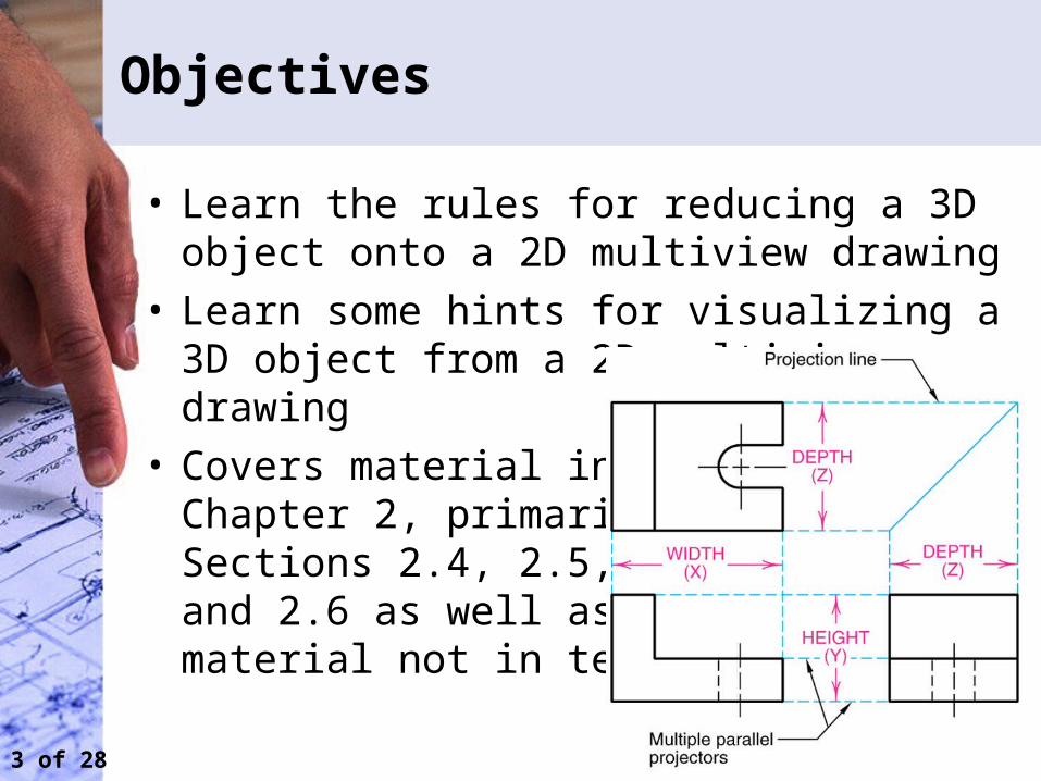
Objectives
• Learn the rules for reducing a 3D object onto a 2D multiview drawing
• Learn some hints for visualizing a 3D object from a 2D multiview drawing
• Covers material in Chapter 2, primarily Sections 2.4, 2.5, and 2.6 as well asmaterial not in text
4 of 28
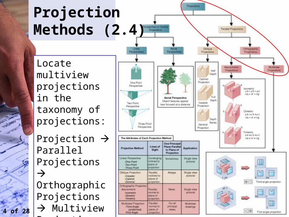
Projection Methods (2.4)
Locate multiview projections in the taxonomy of projections:
Projection Parallel Projections Orthographic Projections Multiview Projections
5 of 28
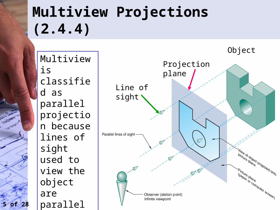
Multiview Projections (2.4.4)
Line of sight
Projection plane
ObjectMultiview is classified as parallel projection because lines of sight used to view the object are parallel
6 of 28
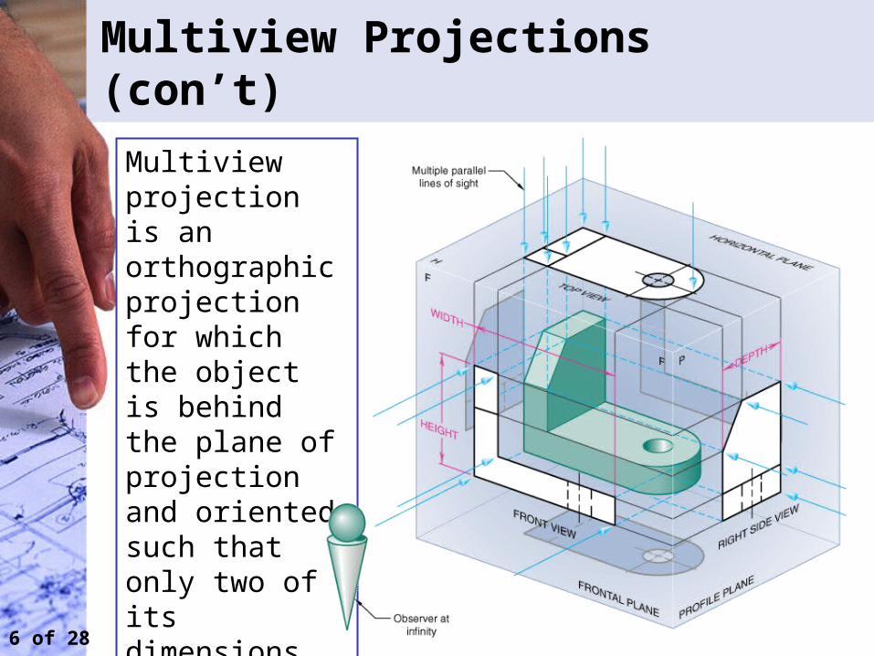
Multiview projection is an orthographic projection for which the object is behind the plane of projection and oriented such that only two of its dimensions are shown
Multiview Projections (con’t)
7 of 28
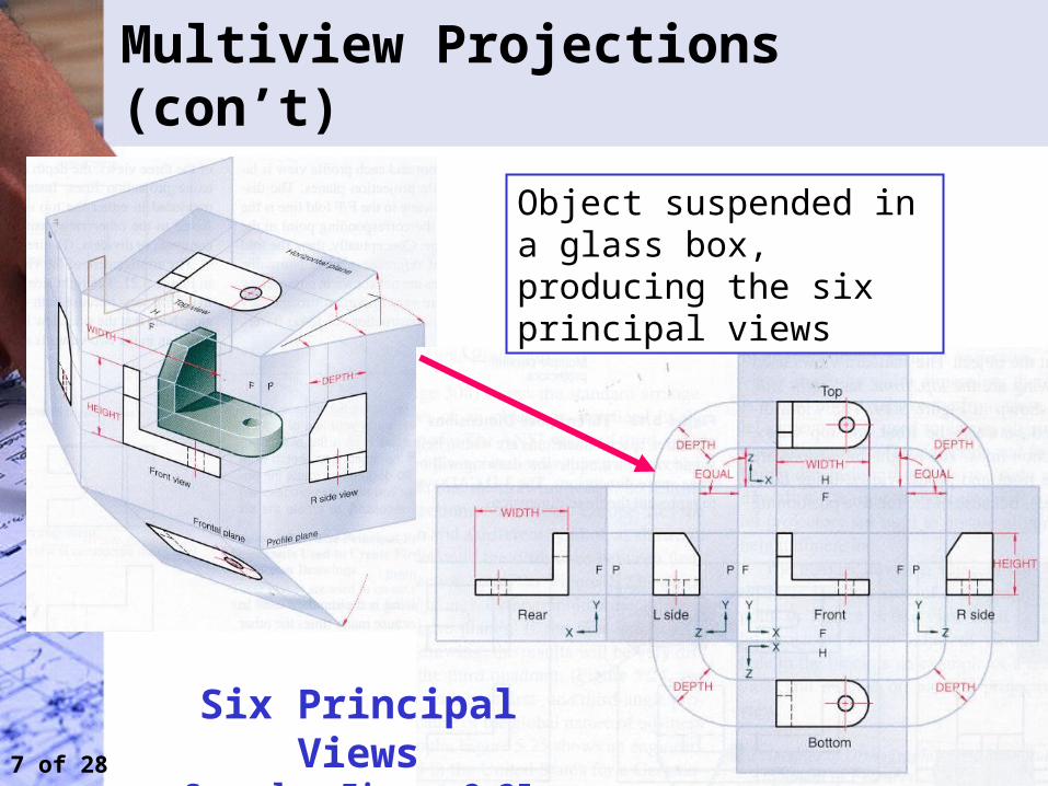
Multiview Projections (con’t)
Object suspended in a glass box, producing the six principal views
Six Principal ViewsSee also Figure 2.35 in text
8 of 28
Multiview Projections (con’t)
• Glass box video:– http://highered.mcgraw-hill.com/sites/007286458
3/student_view0/chapter5/animations.html#
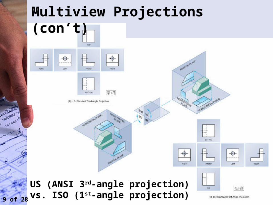
9 of 28
US (ANSI 3rd-angle projection) vs. ISO (1st-angle projection)
Multiview Projections (con’t)
10 of 28
Multiview Projections (con’t)
• Choosing the views and orientation for a multiview object:– Determine the best position of the object– Try to make the surfaces of major features either
perpendicular or parallel to the projection planes– Define the front view (the front view should show
the object in its natural or assembled state)– Determine the minimum number of views
needed to completely describe the object so it can be produced
– Once the front view is selected, determine which other views will have the fewest number of hidden lines
11 of 28
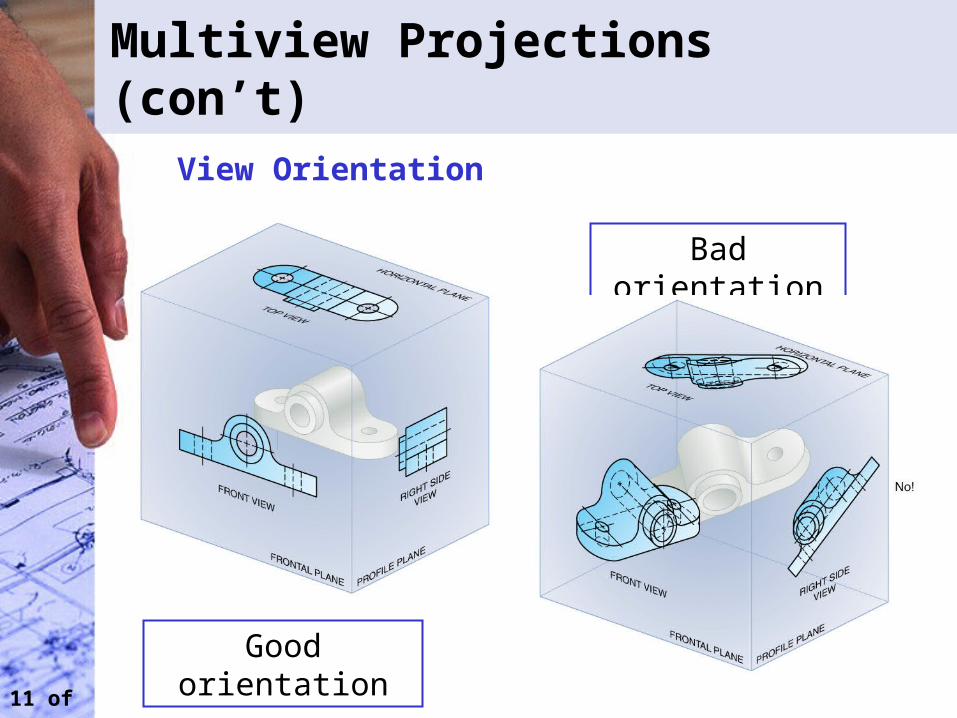
Multiview Projections (con’t)
Good orientation
Bad orientation
View Orientation
12 of 28
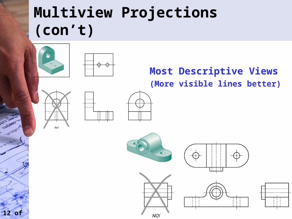
Multiview Projections (con’t)
Most Descriptive Views(More visible lines better)
13 of 28
Multiview Sketches (2.6)
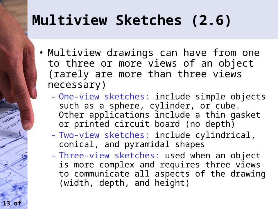
• Multiview drawings can have from one to three or more views of an object (rarely are more than three views necessary)– One-view sketches: include simple objects such as
a sphere, cylinder, or cube. Other applications include a thin gasket or printed circuit board (no depth)
– Two-view sketches: include cylindrical, conical, and pyramidal shapes
– Three-view sketches: used when an object is more complex and requires three views to communicate all aspects of the drawing (width, depth, and height)
14 of 28
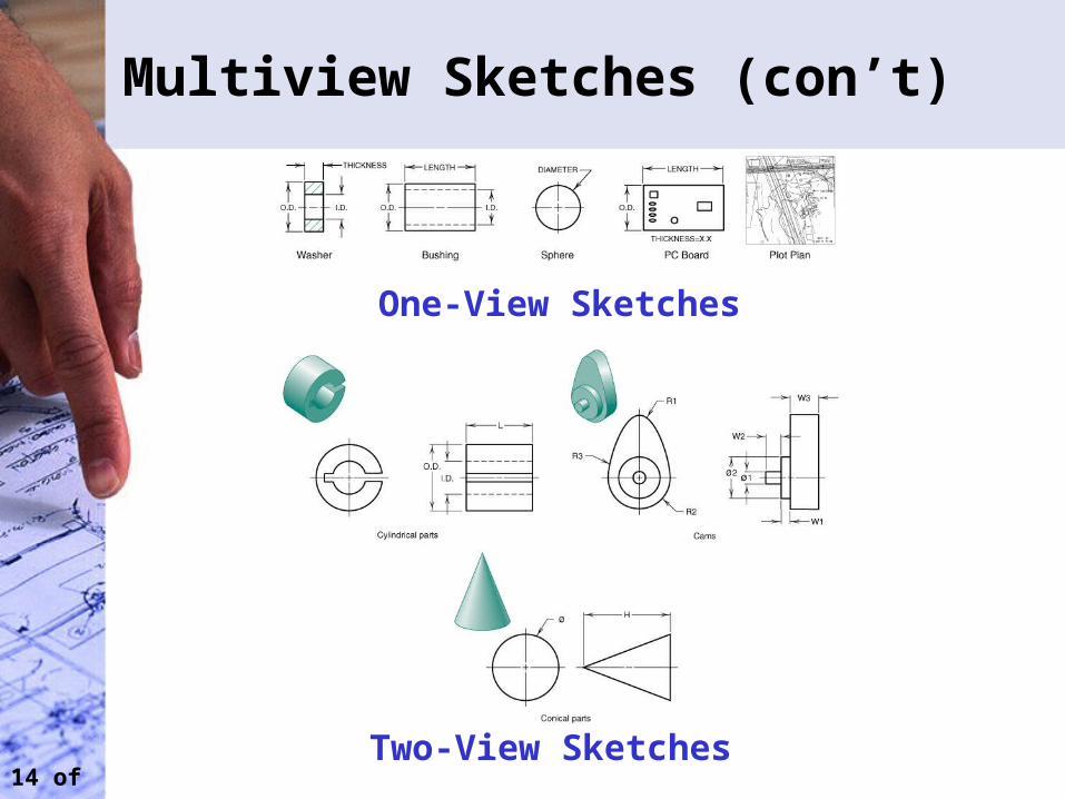
Multiview Sketches (con’t)
One-View Sketches
Two-View Sketches
15 of 28
Multiview Sketches (con’t)
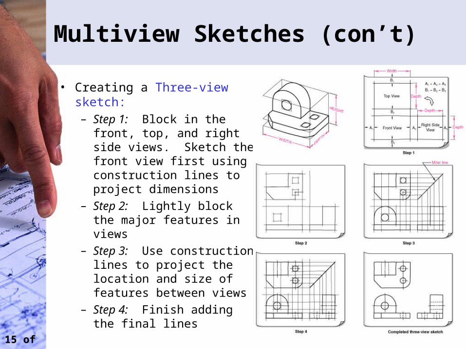
• Creating a Three-view sketch:– Step 1: Block in the front,
top, and right side views. Sketch the front view first using construction lines to project dimensions
– Step 2: Lightly block the major features in views
– Step 3: Use construction lines to project the location and size of features between views
– Step 4: Finish adding the final lines
16 of 28
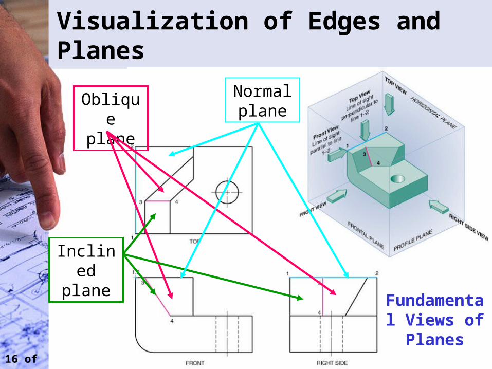
Visualization of Edges and Planes
Oblique plane
Inclined plane
Normal plane
Fundamental Views of Planes
17 of 28
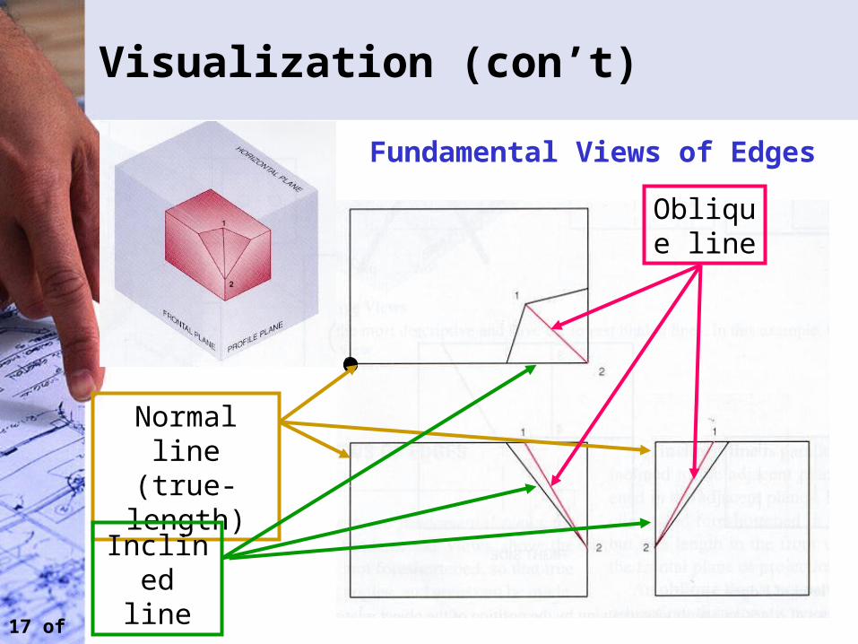
Visualization (con’t)
Normal line (true-
length)
Inclined line
Oblique line
Fundamental Views of Edges
18 of 28
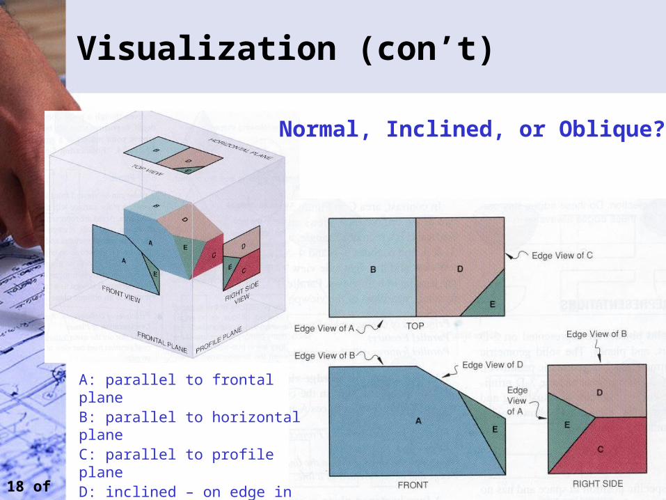
Visualization (con’t)
Normal, Inclined, or Oblique?
A: parallel to frontal planeB: parallel to horizontal planeC: parallel to profile planeD: inclined – on edge in front viewE: oblique – neither parallel or on edge in any plan or view
19 of 28
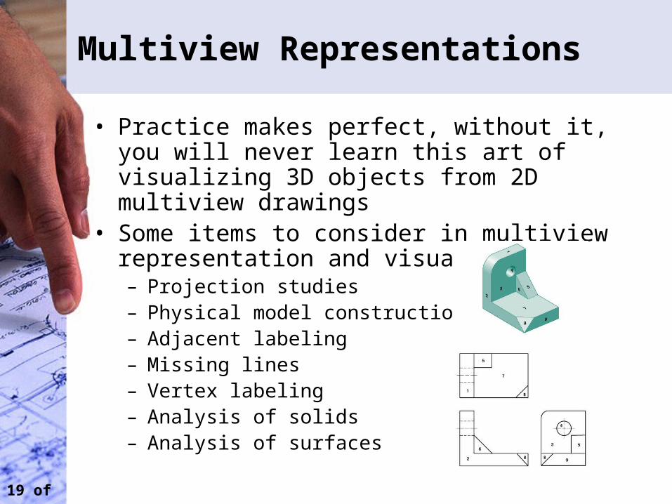
Multiview Representations
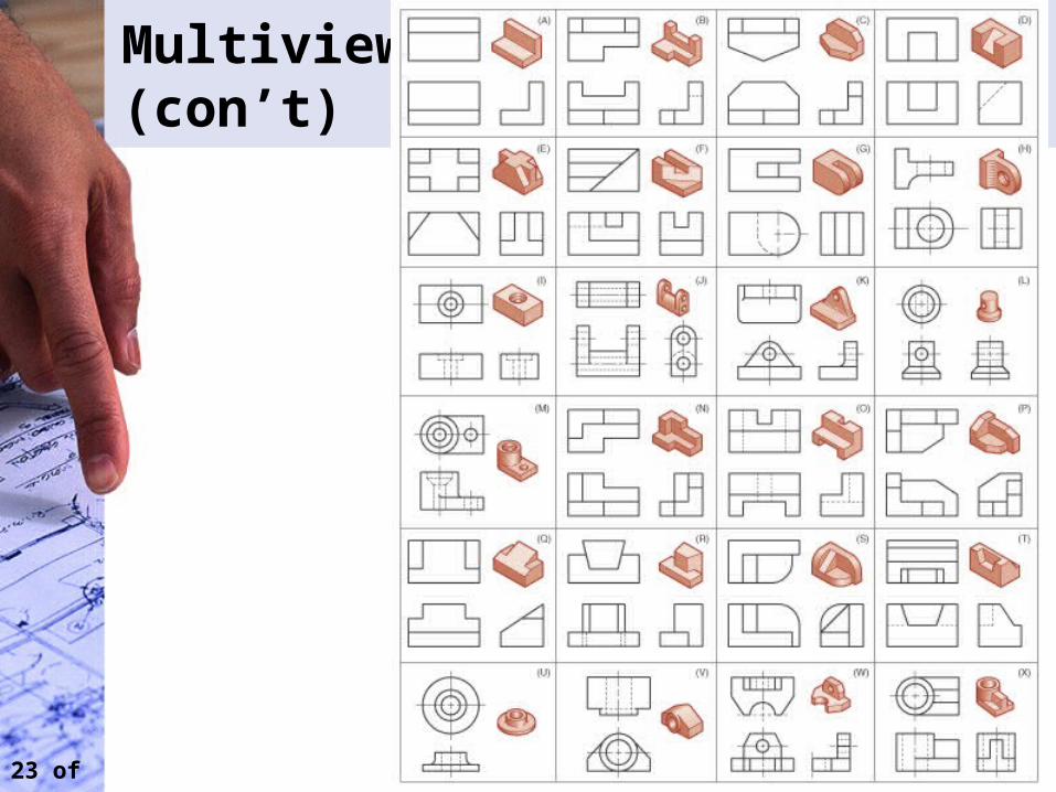
• Practice makes perfect, without it, you will never learn this art of visualizing 3D objects from 2D multiview drawings
• Some items to consider in multiview representation and visualization:– Projection studies– Physical model construction– Adjacent labeling– Missing lines– Vertex labeling– Analysis of solids– Analysis of surfaces
20 of 28
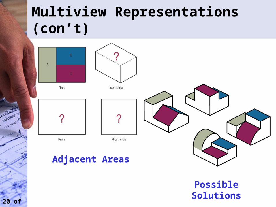
Multiview Representations (con’t)
Adjacent Areas
Possible Solutions
21 of 28
Multiview Representations (con’t)
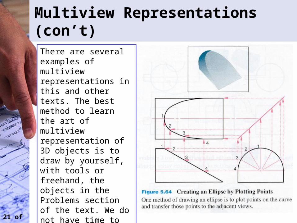
There are several examples of multiview representations in this and other texts. The best method to learn the art of multiview representation of 3D objects is to draw by yourself, with tools or freehand, the objects in the Problems section of the text. We do not have time to cover all that are presented in the chapter. This section presents some examples of multiview representation.
22 of 28
Multiview Representations (con’t)
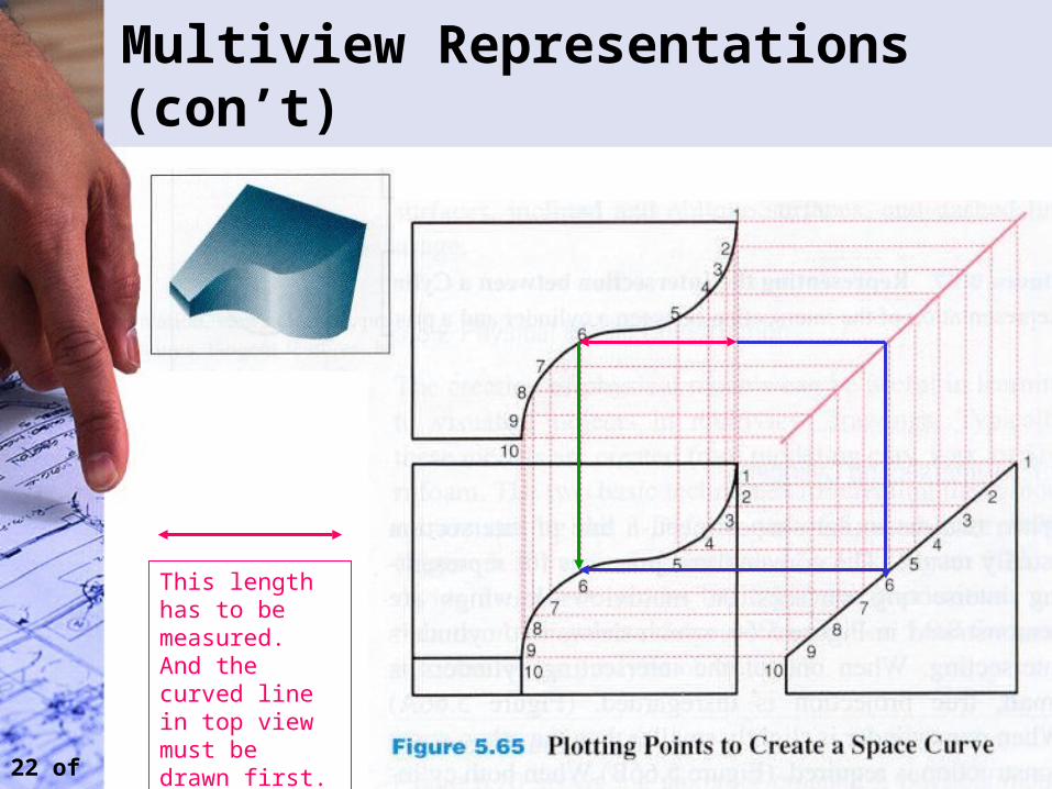
This length has to be measured. And the curved line in top view must be drawn first. (The bottom plane is flat.)
23 of 28
Multiview (con’t)
24 of 28
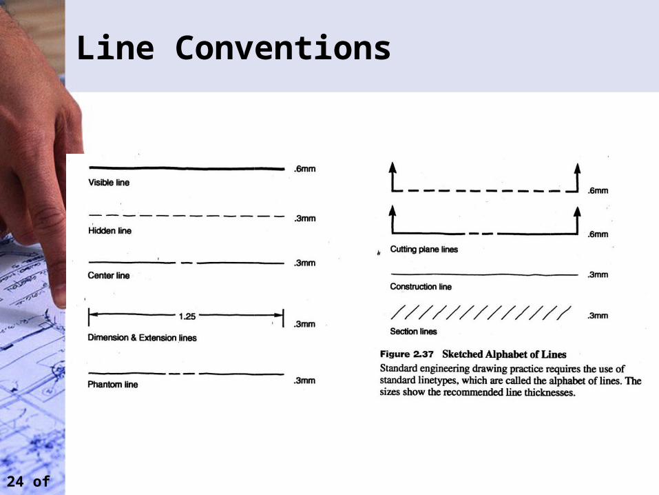
Line Conventions
25 of 28
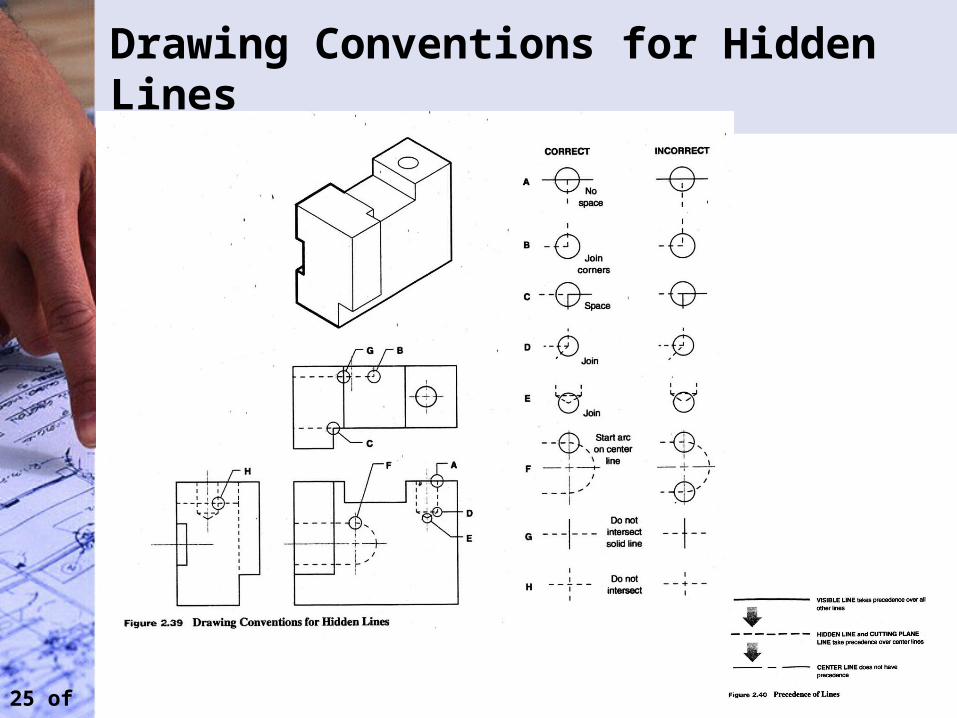
Drawing Conventions for Hidden Lines
26 of 28
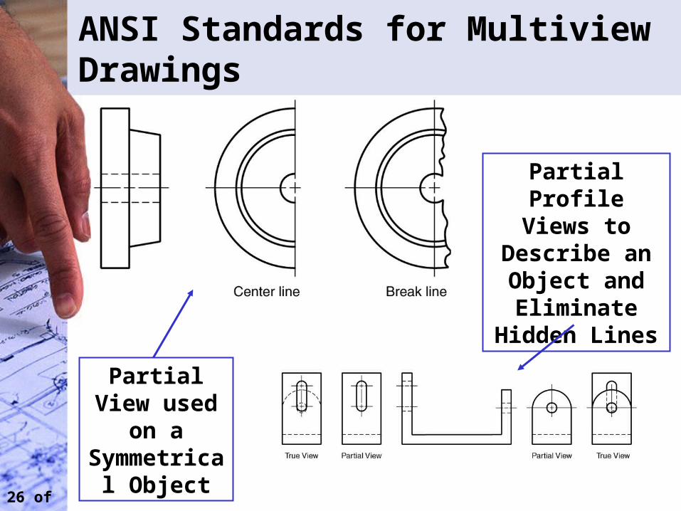
ANSI Standards for Multiview Drawings
Partial View used on a
Symmetrical Object
Partial Profile Views to
Describe an Object and Eliminate
Hidden Lines
27 of 28
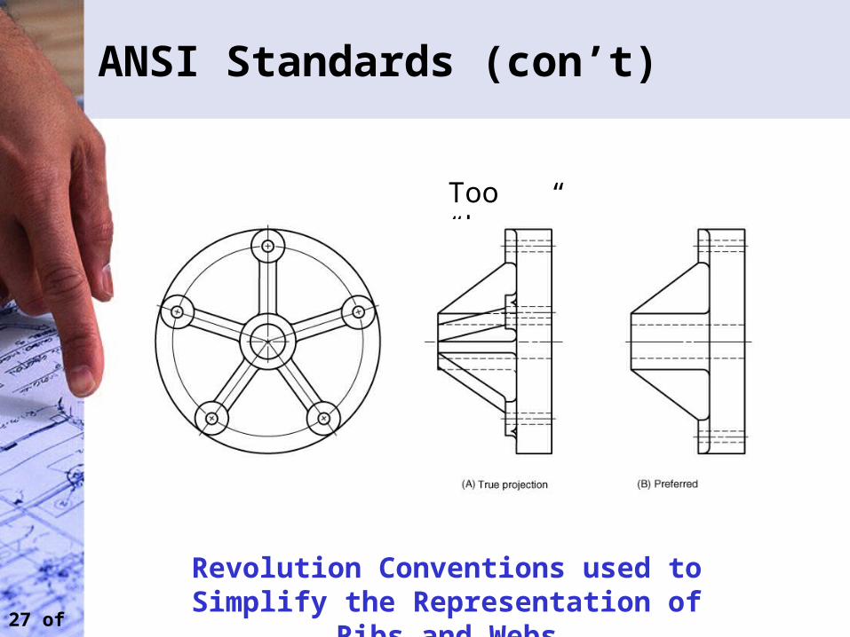
ANSI Standards (con’t)
Too “busy”
Revolution Conventions used to Simplify the Representation of Ribs and Webs
28 of 28
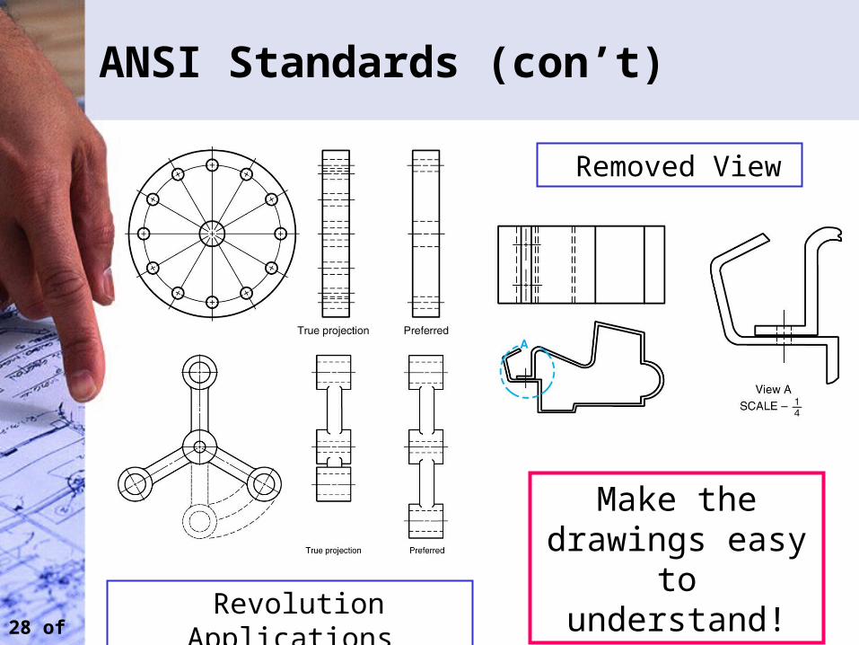
ANSI Standards (con’t)
Removed View
Make the drawings easy to understand!
Revolution Applications
29 of 28
Examples
Use overhead slides
30 of 28
Next Class
• Dimensioning