CE EMC TEST REPORT - doc-fishing.com
44
Shenzhen BCTC Technology Co., Ltd. Report No.: BCTC-160608172-2E Report Tel: 400-788-9558 0755-33019988 Web: Http//www.bctc-lab.com.cn Page 1 of 44 CE EMC TEST REPORT Product: Fishing bite alarm Trade Name: Model Name: JZH-RF898B JZH-RX898B Report No.: BCTC-160608172-2E Prepared for Shenzhen JZH Technology Co., Ltd 3/F, 8 Bldg, Changxing High & New Tech Ind PK, Wanan Road, Shajing Street, Baoan District, Shenzhen, China Prepared by Shenzhen BCTC Technology Co., Ltd. NO. 101, Yousong Road, Longhua New District, Shenzhen, Guangdong P.R.China Tel: 400-788-9558,0755-33019988 Web: Http//www.bctc-lab.com.cn
Transcript of CE EMC TEST REPORT - doc-fishing.com
Shenzhen BCTC Technology Co., Ltd. Report No.: BCTC-160608172-2E
Report Tel: 400-788-9558 0755-33019988 Web: Http//www.bctc-lab.com.cn Page 1 of 44
CE EMC TEST REPORT
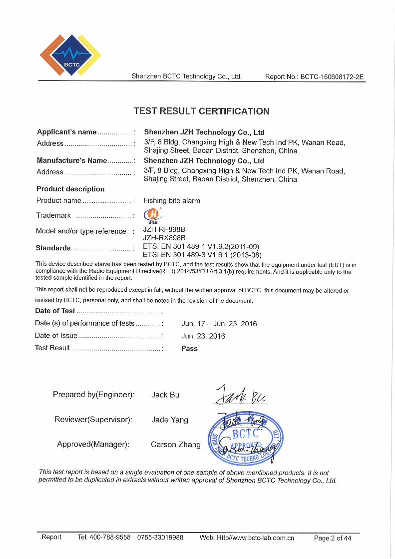
Product: Fishing bite alarm
Trade Name:
Model Name: JZH-RF898B JZH-RX898B
Report No.: BCTC-160608172-2E
Prepared for
Shenzhen JZH Technology Co., Ltd
3/F, 8 Bldg, Changxing High & New Tech Ind PK, Wanan Road, Shajing Street, Baoan District, Shenzhen, China
Prepared by
Shenzhen BCTC Technology Co., Ltd. NO. 101, Yousong Road, Longhua New District, Shenzhen, Guangdong
P.R.China Tel: 400-788-9558,0755-33019988
Web: Http//www.bctc-lab.com.cn
Shenzhen BCTC Technology Co., Ltd. Report No.: BCTC-160608172-2E
Report Tel: 400-788-9558 0755-33019988 Web: Http//www.bctc-lab.com.cn Page 3 of 44
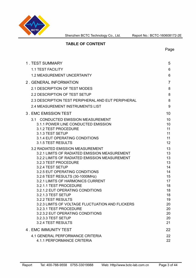
TABLE OF CONTENT Page
1 . TEST SUMMARY 5
1.1 TEST FACILITY 6
1.2 MEASUREMENT UNCERTAINTY 6
2 . GENERAL INFORMATION 7
2.1 DESCRIPTION OF TEST MODES 8
2.2 DESCRIPTION OF TEST SETUP 8
2.3 DESCRIPTION TEST PERIPHERAL AND EUT PERIPHERAL 8
2.4 MEASUREMENT INSTRUMENTS LIST 9
3 . EMC EMISSION TEST 10
3.1 CONDUCTED EMISSION MEASUREMENT 10 3.1.1 POWER LINE CONDUCTED EMISSION 10 3.1.2 TEST PROCEDURE 11 3.1.3 TEST SETUP 11 3.1.4 EUT OPERATING CONDITIONS 11 3.1.5 TEST RESULTS 12
3.2 RADIATED EMISSION MEASUREMENT 13 3.2.1 LIMITS OF RADIATED EMISSION MEASUREMENT 13 3.2.2 LIMITS OF RADIATED EMISSION MEASUREMENT 13 3.2.3 TEST PROCEDURE 13 3.2.4 TEST SETUP 14 3.2.5 EUT OPERATING CONDITIONS 14 3.2.6 TEST RESULTS (30-1000MHz) 15 3.2.1 LIMITS OF HARMONICS CURRENT 17 3.2.1.1 TEST PROCEDURE 18 3.2.1.2 EUT OPERATING CONDITIONS 18 3.2.1.3 TEST SETUP 18 3.2.2 TEST RESULTS 19 3.2.3 LIMITS OF VOLTAGE FLUCTUATION AND FLICKERS 20 3.2.3.1 TEST PROCEDURE 20 3.2.3.2 EUT OPERATING CONDITIONS 20 3.2.3.3 TEST SETUP 20 3.2.4 TEST RESULTS 21
4 . EMC IMMUNITY TEST 22
4.1 GENERAL PERFORMANCE CRITERIA 22 4.1.1 PERFORMANCE CRITERIA 22
Shenzhen BCTC Technology Co., Ltd. Report No.: BCTC-160608172-2E
Report Tel: 400-788-9558 0755-33019988 Web: Http//www.bctc-lab.com.cn Page 4 of 44
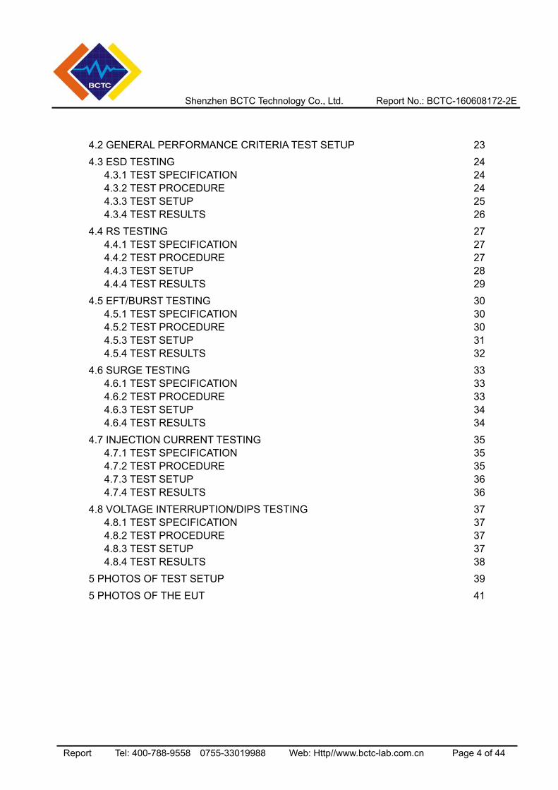
4.2 GENERAL PERFORMANCE CRITERIA TEST SETUP 23
4.3 ESD TESTING 24 4.3.1 TEST SPECIFICATION 24 4.3.2 TEST PROCEDURE 24 4.3.3 TEST SETUP 25 4.3.4 TEST RESULTS 26
4.4 RS TESTING 27 4.4.1 TEST SPECIFICATION 27 4.4.2 TEST PROCEDURE 27 4.4.3 TEST SETUP 28 4.4.4 TEST RESULTS 29
4.5 EFT/BURST TESTING 30 4.5.1 TEST SPECIFICATION 30 4.5.2 TEST PROCEDURE 30 4.5.3 TEST SETUP 31 4.5.4 TEST RESULTS 32
4.6 SURGE TESTING 33 4.6.1 TEST SPECIFICATION 33 4.6.2 TEST PROCEDURE 33 4.6.3 TEST SETUP 34 4.6.4 TEST RESULTS 34
4.7 INJECTION CURRENT TESTING 35 4.7.1 TEST SPECIFICATION 35 4.7.2 TEST PROCEDURE 35 4.7.3 TEST SETUP 36 4.7.4 TEST RESULTS 36
4.8 VOLTAGE INTERRUPTION/DIPS TESTING 37 4.8.1 TEST SPECIFICATION 37 4.8.2 TEST PROCEDURE 37 4.8.3 TEST SETUP 37 4.8.4 TEST RESULTS 38
5 PHOTOS OF TEST SETUP 39
5 PHOTOS OF THE EUT 41
Shenzhen BCTC Technology Co., Ltd. Report No.: BCTC-160608172-2E
Report Tel: 400-788-9558 0755-33019988 Web: Http//www.bctc-lab.com.cn Page 5 of 44
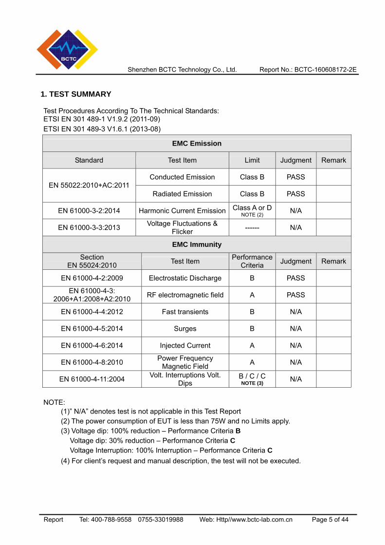
1. TEST SUMMARY
Test Procedures According To The Technical Standards: ETSI EN 301 489-1 V1.9.2 (2011-09) ETSI EN 301 489-3 V1.6.1 (2013-08)
EMC Emission
Standard Test Item Limit Judgment Remark
Conducted Emission Class B PASS EN 55022:2010+AC:2011
Radiated Emission Class B PASS
EN 61000-3-2:2014 Harmonic Current Emission Class A or DNOTE (2) N/A
EN 61000-3-3:2013 Voltage Fluctuations & Flicker ------ N/A
EMC Immunity
Section EN 55024:2010 Test Item Performance
Criteria Judgment Remark
EN 61000-4-2:2009 Electrostatic Discharge B PASS
EN 61000-4-3: 2006+A1:2008+A2:2010 RF electromagnetic field A PASS
EN 61000-4-4:2012 Fast transients B N/A
EN 61000-4-5:2014 Surges B N/A
EN 61000-4-6:2014 Injected Current A N/A
EN 61000-4-8:2010 Power Frequency Magnetic Field A N/A
EN 61000-4-11:2004 Volt. Interruptions Volt. Dips
B / C / C NOTE (3) N/A
NOTE: (1)” N/A” denotes test is not applicable in this Test Report (2) The power consumption of EUT is less than 75W and no Limits apply. (3) Voltage dip: 100% reduction – Performance Criteria B Voltage dip: 30% reduction – Performance Criteria C Voltage Interruption: 100% Interruption – Performance Criteria C (4) For client’s request and manual description, the test will not be executed.
Shenzhen BCTC Technology Co., Ltd. Report No.: BCTC-160607076-2E
Report Tel: 400-788-9558 0755-33019988 Web: Http//www.bctc-lab.com.cn Page 6 of 44
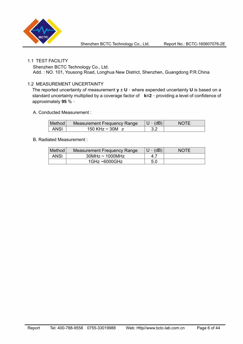
1.1 TEST FACILITY Shenzhen BCTC Technology Co., Ltd.
Add. : NO. 101, Yousong Road, Longhua New District, Shenzhen, Guangdong P.R.China 1.2 MEASUREMENT UNCERTAINTY The reported uncertainty of measurement y ± U,where expended uncertainty U is based on a
standard uncertainty multiplied by a coverage factor of k=2,providing a level of confidence of approximately 95 %。 A. Conducted Measurement :
Method Measurement Frequency Range U,(dB) NOTE ANSI 150 KHz ~ 30M z 3.2
B. Radiated Measurement :
Method Measurement Frequency Range U,(dB) NOTE ANSI 30MHz ~ 1000MHz 4.7
1GHz ~6000GHz 5.0
Shenzhen BCTC Technology Co., Ltd. Report No.: BCTC-160607076-2E
Report Tel: 400-788-9558 0755-33019988 Web: Http//www.bctc-lab.com.cn Page 7 of 44
2. GENERAL INFORMATION
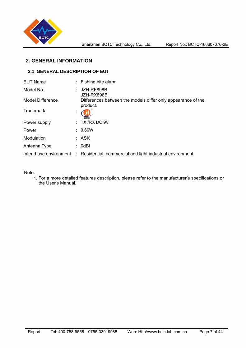
2.1 GENERAL DESCRIPTION OF EUT EUT Name : Fishing bite alarm
Model No. : JZH-RF898B JZH-RX898B
Model Difference Differences between the models differ only appearance of the product.
Trademark :
Power supply : TX /RX DC 9V
Power : 0.66W
Modulation : ASK
Antenna Type : 0dBi
Intend use environment : Residential, commercial and light industrial environment
Note:
1. For a more detailed features description, please refer to the manufacturer’s specifications or the User's Manual.
Shenzhen BCTC Technology Co., Ltd. Report No.: BCTC-160607076-2E
Report Tel: 400-788-9558 0755-33019988 Web: Http//www.bctc-lab.com.cn Page 8 of 44
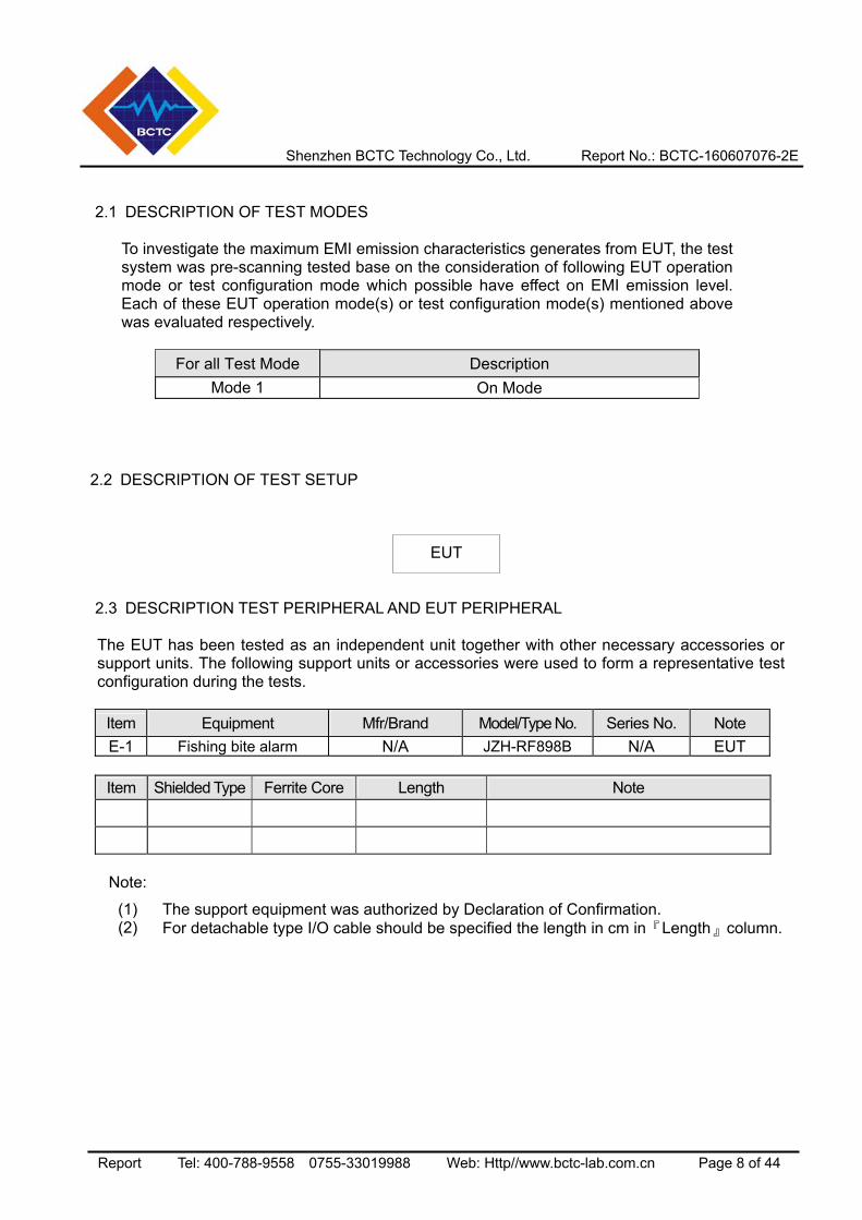
2.1 DESCRIPTION OF TEST MODES
To investigate the maximum EMI emission characteristics generates from EUT, the test system was pre-scanning tested base on the consideration of following EUT operation mode or test configuration mode which possible have effect on EMI emission level. Each of these EUT operation mode(s) or test configuration mode(s) mentioned above was evaluated respectively.
For all Test Mode Description Mode 1 On Mode
2.2 DESCRIPTION OF TEST SETUP
2.3 DESCRIPTION TEST PERIPHERAL AND EUT PERIPHERAL
The EUT has been tested as an independent unit together with other necessary accessories or support units. The following support units or accessories were used to form a representative test configuration during the tests.
Item Equipment Mfr/Brand Model/Type No. Series No. Note E-1 Fishing bite alarm N/A JZH-RF898B N/A EUT
Item Shielded Type Ferrite Core Length Note
Note:
(1) The support equipment was authorized by Declaration of Confirmation. (2) For detachable type I/O cable should be specified the length in cm in『Length』column.
EUT
Shenzhen BCTC Technology Co., Ltd. Report No.: BCTC-160607076-2E
Report Tel: 400-788-9558 0755-33019988 Web: Http//www.bctc-lab.com.cn Page 9 of 44
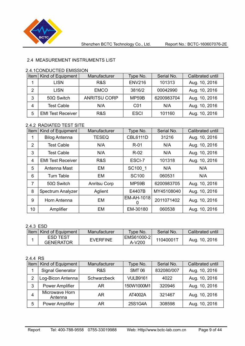
2.4 MEASUREMENT INSTRUMENTS LIST
2.4.1CONDUCTED EMISSION
Item Kind of Equipment Manufacturer Type No. Serial No. Calibrated until 1 LISN R&S ENV216 101313 Aug. 10, 2016
2 LISN EMCO 3816/2 00042990 Aug. 10, 2016
3 50Ω Switch ANRITSU CORP MP59B 6200983704 Aug. 10, 2016
4 Test Cable N/A C01 N/A Aug. 10, 2016
5 EMI Test Receiver R&S ESCI 101160 Aug. 10, 2016 2.4.2 RADIATED TEST SITE
Item Kind of Equipment Manufacturer Type No. Serial No. Calibrated until 1 Bilog Antenna TESEQ CBL6111D 31216 Aug. 10, 2016
2 Test Cable N/A R-01 N/A Aug. 10, 2016
3 Test Cable N/A R-02 N/A Aug. 10, 2016
4 EMI Test Receiver R&S ESCI-7 101318 Aug. 10, 2016
5 Antenna Mast EM SC100_1 N/A N/A
6 Turn Table EM SC100 060531 N/A
7 50Ω Switch Anritsu Corp MP59B 6200983705 Aug. 10, 2016
8 Spectrum Analyzer Aglient E4407B MY45108040 Aug. 10, 2016
9 Horn Antenna EM EM-AH-10180 2011071402 Aug. 10, 2016
10 Amplifier EM EM-30180 060538 Aug. 10, 2016 2.4.3 ESD
Item Kind of Equipment Manufacturer Type No. Serial No. Calibrated until
1 ESD TEST GENERATOR EVERFINE EMS61000-2
A-V200 11040001T Aug. 10, 2016
2.4.4 RS Item Kind of Equipment Manufacturer Type No. Serial No. Calibrated until
1 Signal Generator R&S SMT 06 832080/007 Aug. 10, 2016
2 Log-Bicon Antenna Schwarzbeck VULB9161 4022 Aug. 10, 2016
3 Power Amplifier AR 150W1000M1 320946 Aug. 10, 2016
4 Microwave Horn Antenna AR AT4002A 321467 Aug. 10, 2016
5 Power Amplifier AR 25S1G4A 308598 Aug. 10, 2016
Shenzhen BCTC Technology Co., Ltd. Report No.: BCTC-160607076-2E
Report Tel: 400-788-9558 0755-33019988 Web: Http//www.bctc-lab.com.cn Page 10 of 44
3. EMC EMISSION TEST
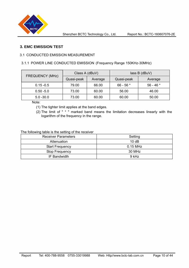
3.1 CONDUCTED EMISSION MEASUREMENT 3.1.1 POWER LINE CONDUCTED EMISSION (Frequency Range 150KHz-30MHz)
Class A (dBuV) lass B (dBuV) FREQUENCY (MHz)
Quasi-peak Average Quasi-peak Average
0.15 -0.5 79.00 66.00 66 - 56 * 56 - 46 *
0.50 -5.0 73.00 60.00 56.00 46.00
5.0 -30.0 73.00 60.00 60.00 50.00 Note: (1) The tighter limit applies at the band edges. (2) The limit of " * " marked band means the limitation decreases linearly with the
logarithm of the frequency in the range.
The following table is the setting of the receiver Receiver Parameters Setting
Attenuation 10 dB Start Frequency 0.15 MHz Stop Frequency 30 MHz
IF Bandwidth 9 kHz
Shenzhen BCTC Technology Co., Ltd. Report No.: BCTC-160607076-2E
Report Tel: 400-788-9558 0755-33019988 Web: Http//www.bctc-lab.com.cn Page 11 of 44
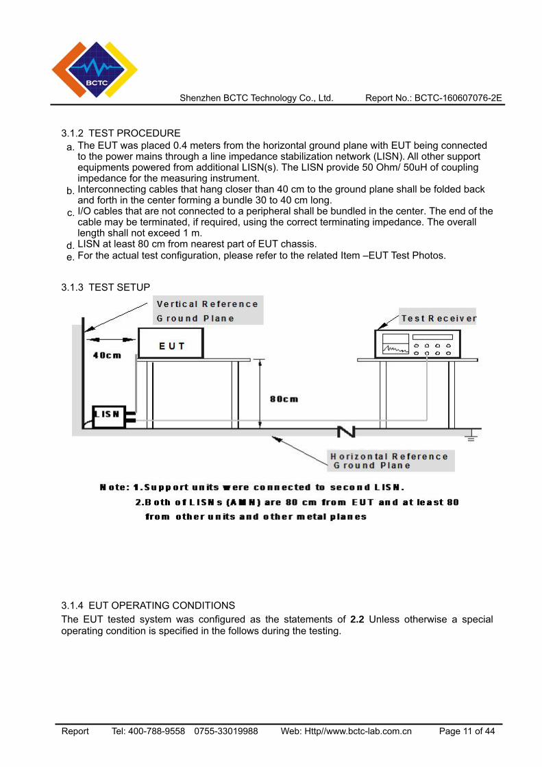
3.1.2 TEST PROCEDURE a. The EUT was placed 0.4 meters from the horizontal ground plane with EUT being connected
to the power mains through a line impedance stabilization network (LISN). All other support equipments powered from additional LISN(s). The LISN provide 50 Ohm/ 50uH of coupling impedance for the measuring instrument.
b. Interconnecting cables that hang closer than 40 cm to the ground plane shall be folded back and forth in the center forming a bundle 30 to 40 cm long.
c. I/O cables that are not connected to a peripheral shall be bundled in the center. The end of the cable may be terminated, if required, using the correct terminating impedance. The overall length shall not exceed 1 m.
d. LISN at least 80 cm from nearest part of EUT chassis. e. For the actual test configuration, please refer to the related Item –EUT Test Photos.
3.1.3 TEST SETUP
3.1.4 EUT OPERATING CONDITIONS The EUT tested system was configured as the statements of 2.2 Unless otherwise a special operating condition is specified in the follows during the testing.
Shenzhen BCTC Technology Co., Ltd. Report No.: BCTC-160607076-2E
Report Tel: 400-788-9558 0755-33019988 Web: Http//www.bctc-lab.com.cn Page 12 of 44
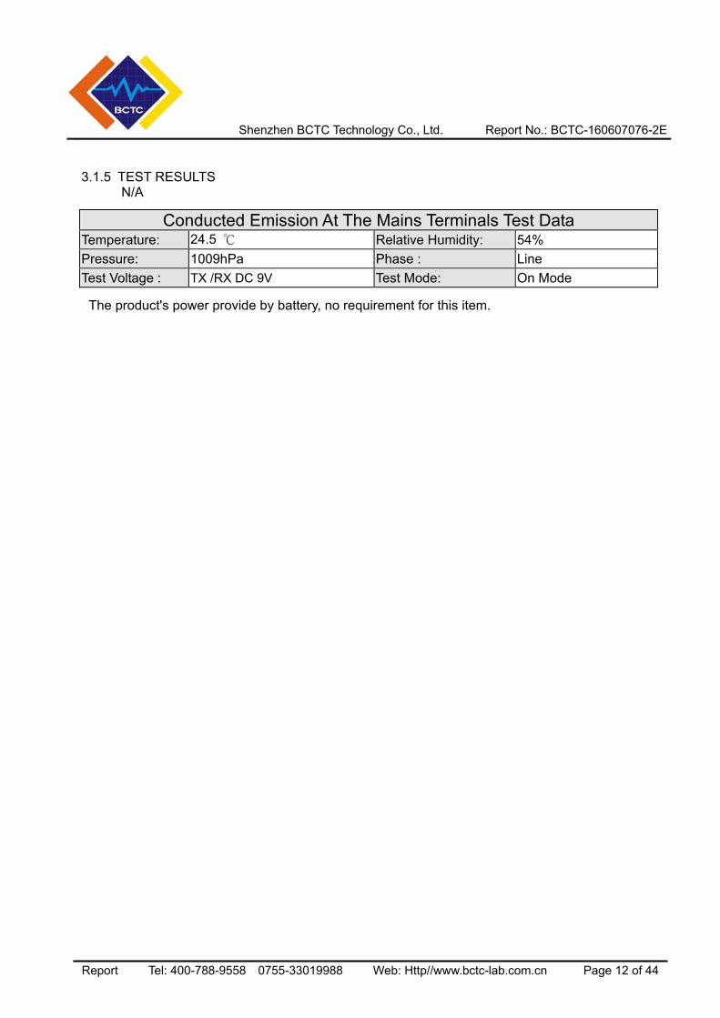
3.1.5 TEST RESULTS N/A
Conducted Emission At The Mains Terminals Test Data
Temperature: 24.5 Relative Humidity: 54% Pressure: 1009hPa Phase : Line Test Voltage : TX /RX DC 9V Test Mode: On Mode
The product's power provide by battery, no requirement for this item.
Shenzhen BCTC Technology Co., Ltd. Report No.: BCTC-160607076-2E
Report Tel: 400-788-9558 0755-33019988 Web: Http//www.bctc-lab.com.cn Page 13 of 44
3.2 RADIATED EMISSION MEASUREMENT
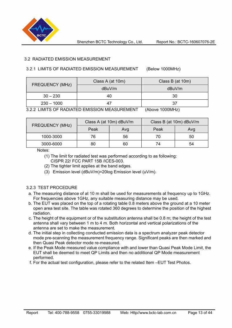
3.2.1 LIMITS OF RADIATED EMISSION MEASUREMENT (Below 1000MHz)
Class A (at 10m) Class B (at 10m) FREQUENCY (MHz)
dBuV/m dBuV/m
30 – 230 40 30
230 – 1000 47 37 3.2.2 LIMITS OF RADIATED EMISSION MEASUREMENT (Above 1000MHz)
Class A (at 10m) dBuV/m Class B (at 10m) dBuV/m FREQUENCY (MHz)
Peak Avg Peak Avg
1000-3000 76 56 70 50
3000-6000 80 60 74 54 Notes: (1) The limit for radiated test was performed according to as following:
CISPR 22/ FCC PART 15B /ICES-003. (2) The tighter limit applies at the band edges. (3) Emission level (dBuV/m)=20log Emission level (uV/m).
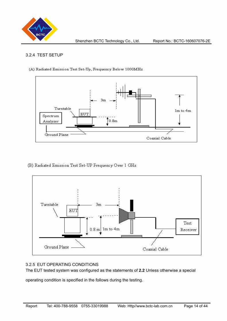
3.2.3 TEST PROCEDURE a. The measuring distance of at 10 m shall be used for measurements at frequency up to 1GHz.
For frequencies above 1GHz, any suitable measuring distance may be used. b. The EUT was placed on the top of a rotating table 0.8 meters above the ground at a 10 meter
open area test site. The table was rotated 360 degrees to determine the position of the highest radiation.
c. The height of the equipment or of the substitution antenna shall be 0.8 m; the height of the test antenna shall vary between 1 m to 4 m. Both horizontal and vertical polarizations of the antenna are set to make the measurement.
d. The initial step in collecting conducted emission data is a spectrum analyzer peak detector mode pre-scanning the measurement frequency range. Significant peaks are then marked and then Quasi Peak detector mode re-measured.
e. If the Peak Mode measured value compliance with and lower than Quasi Peak Mode Limit, the EUT shall be deemed to meet QP Limits and then no additional QP Mode measurement performed.
f. For the actual test configuration, please refer to the related Item –EUT Test Photos.
Shenzhen BCTC Technology Co., Ltd. Report No.: BCTC-160607076-2E
Report Tel: 400-788-9558 0755-33019988 Web: Http//www.bctc-lab.com.cn Page 14 of 44
3.2.4 TEST SETUP
3.2.5 EUT OPERATING CONDITIONS The EUT tested system was configured as the statements of 2.2 Unless otherwise a special operating condition is specified in the follows during the testing.
Shenzhen BCTC Technology Co., Ltd. Report No.: BCTC-160607076-2E
Report Tel: 400-788-9558 0755-33019988 Web: Http//www.bctc-lab.com.cn Page 15 of 44
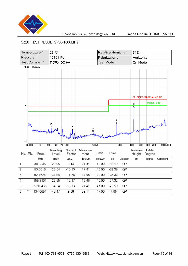
3.2.6 TEST RESULTS (30-1000MHz) Temperature: 26 Relative Humidity: 54% Pressure: 1010 hPa Polarization : Horizontal Test Voltage : TX/RX DC 9V Test Mode: On Mode
Shenzhen BCTC Technology Co., Ltd. Report No.: BCTC-160607076-2E
Report Tel: 400-788-9558 0755-33019988 Web: Http//www.bctc-lab.com.cn Page 16 of 44
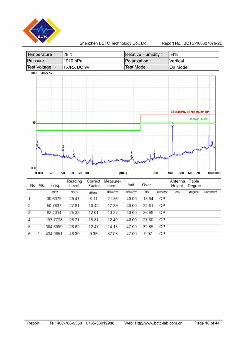
Temperature: 26 Relative Humidity: 54% Pressure: 1010 hPa Polarization : Vertical Test Voltage : TX/RX DC 9V Test Mode: On Mode
Shenzhen BCTC Technology Co., Ltd. Report No.: BCTC-160607076-2E
Report Tel: 400-788-9558 0755-33019988 Web: Http//www.bctc-lab.com.cn Page 17 of 44
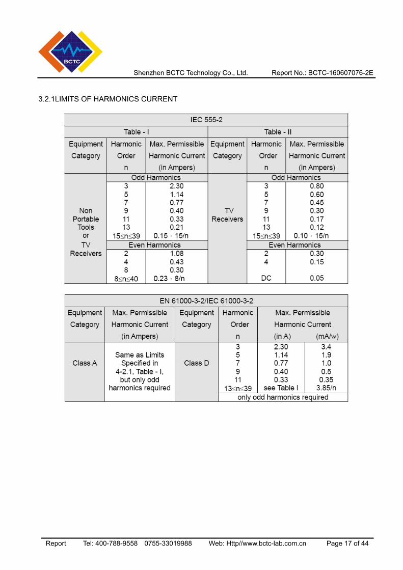
3.2.1LIMITS OF HARMONICS CURRENT
Shenzhen BCTC Technology Co., Ltd. Report No.: BCTC-160607076-2E
Report Tel: 400-788-9558 0755-33019988 Web: Http//www.bctc-lab.com.cn Page 18 of 44
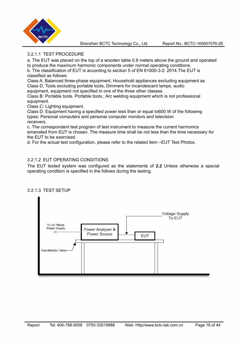
3.2.1.1 TEST PROCEDURE a. The EUT was placed on the top of a wooden table 0.8 meters above the ground and operatedto produce the maximum harmonic components under normal operating conditions. b. The classification of EUT is according to section 5 of EN 61000-3-2: 2014.The EUT is classified as follows: Class A: Balanced three-phase equipment, Household appliances excluding equipment as Class D, Tools excluding portable tools, Dimmers for incandescent lamps, audio equipment, equipment not specified in one of the three other classes. Class B: Portable tools. Portable tools.; Arc welding equipment which is not professional equipment. Class C: Lighting equipment. Class D: Equipment having a specified power less than or equal to600 W of the following types: Personal computers and personal computer monitors and television receivers. c. The correspondent test program of test instrument to measure the current harmonics emanated from EUT is chosen. The measure time shall be not less than the time necessary for the EUT to be exercised. d. For the actual test configuration, please refer to the related item –EUT Test Photos.
3.2.1.2 EUT OPERATING CONDITIONS The EUT tested system was configured as the statements of 2.2 Unless otherwise a special operating condition is specified in the follows during the testing.
3.2.1.3 TEST SETUP
Shenzhen BCTC Technology Co., Ltd. Report No.: BCTC-160607076-2E
Report Tel: 400-788-9558 0755-33019988 Web: Http//www.bctc-lab.com.cn Page 19 of 44
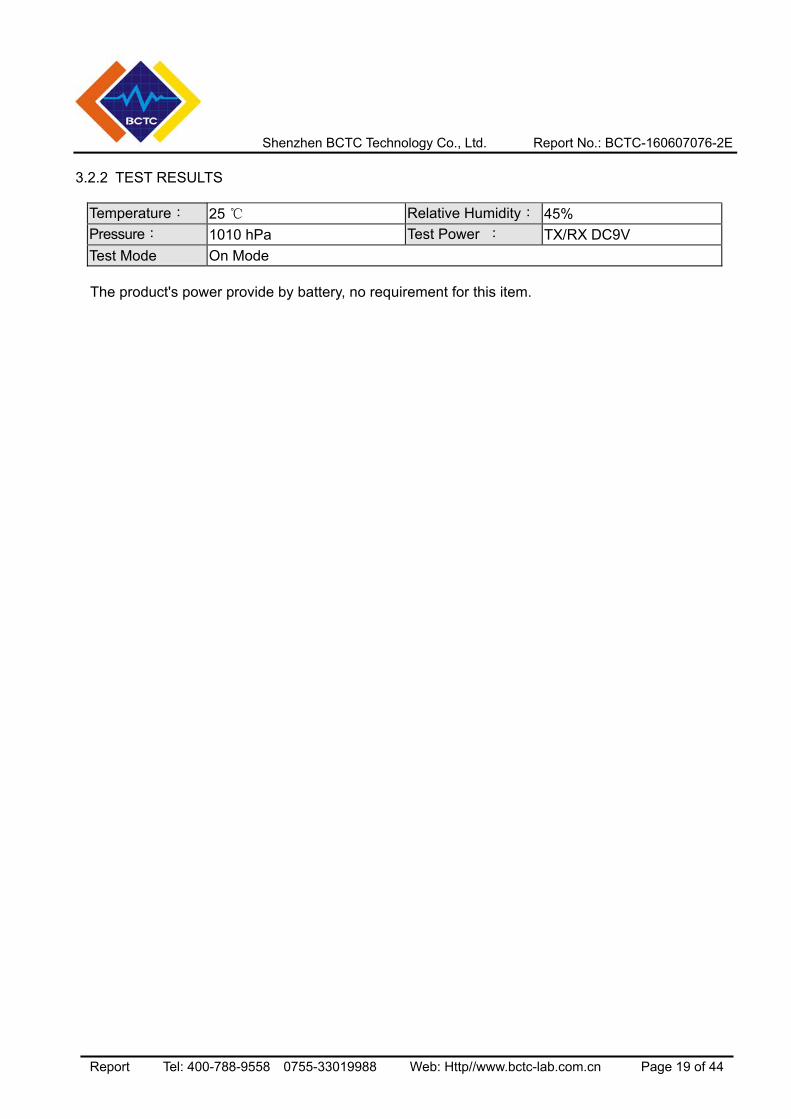
3.2.2 TEST RESULTS
Temperature: 25 Relative Humidity: 45% Pressure: 1010 hPa Test Power : TX/RX DC9V Test Mode On Mode
The product's power provide by battery, no requirement for this item.
Shenzhen BCTC Technology Co., Ltd. Report No.: BCTC-160607076-2E
Report Tel: 400-788-9558 0755-33019988 Web: Http//www.bctc-lab.com.cn Page 20 of 44
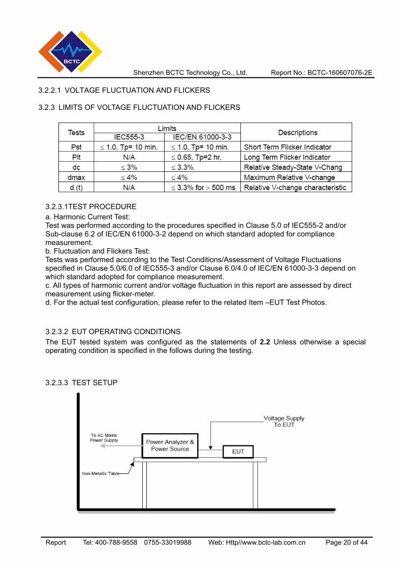
3.2.2.1 VOLTAGE FLUCTUATION AND FLICKERS 3.2.3 LIMITS OF VOLTAGE FLUCTUATION AND FLICKERS
3.2.3.1TEST PROCEDURE a. Harmonic Current Test: Test was performed according to the procedures specified in Clause 5.0 of IEC555-2 and/or Sub-clause 6.2 of IEC/EN 61000-3-2 depend on which standard adopted for compliance measurement. b. Fluctuation and Flickers Test: Tests was performed according to the Test Conditions/Assessment of Voltage Fluctuations specified in Clause 5.0/6.0 of IEC555-3 and/or Clause 6.0/4.0 of IEC/EN 61000-3-3 depend on which standard adopted for compliance measurement. c. All types of harmonic current and/or voltage fluctuation in this report are assessed by direct measurement using flicker-meter. d. For the actual test configuration, please refer to the related Item –EUT Test Photos.
3.2.3.2 EUT OPERATING CONDITIONS The EUT tested system was configured as the statements of 2.2 Unless otherwise a special operating condition is specified in the follows during the testing.
3.2.3.3 TEST SETUP
Shenzhen BCTC Technology Co., Ltd. Report No.: BCTC-160607076-2E
Report Tel: 400-788-9558 0755-33019988 Web: Http//www.bctc-lab.com.cn Page 21 of 44
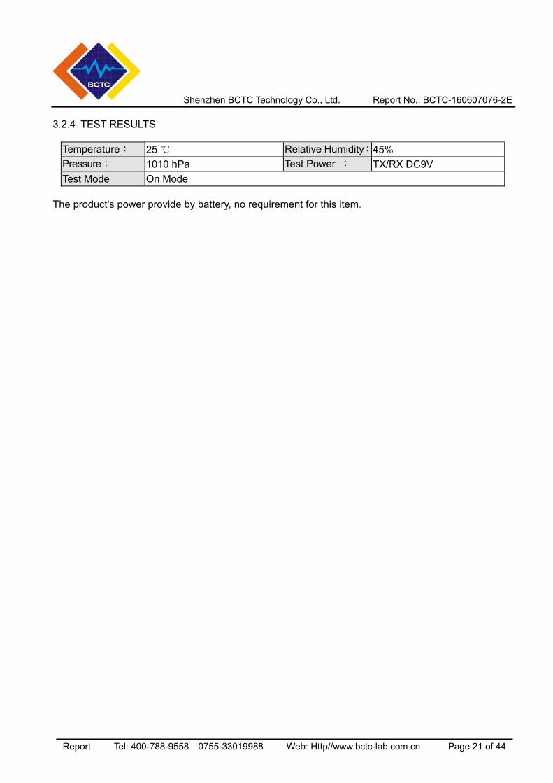
3.2.4 TEST RESULTS
Temperature: 25 Relative Humidity:45% Pressure: 1010 hPa Test Power : TX/RX DC9V Test Mode On Mode
The product's power provide by battery, no requirement for this item.
Shenzhen BCTC Technology Co., Ltd. Report No.: BCTC-160607076-2E
Report Tel: 400-788-9558 0755-33019988 Web: Http//www.bctc-lab.com.cn Page 22 of 44
4. EMC IMMUNITY TEST 4.1 GENERAL PERFORMANCE CRITERIA
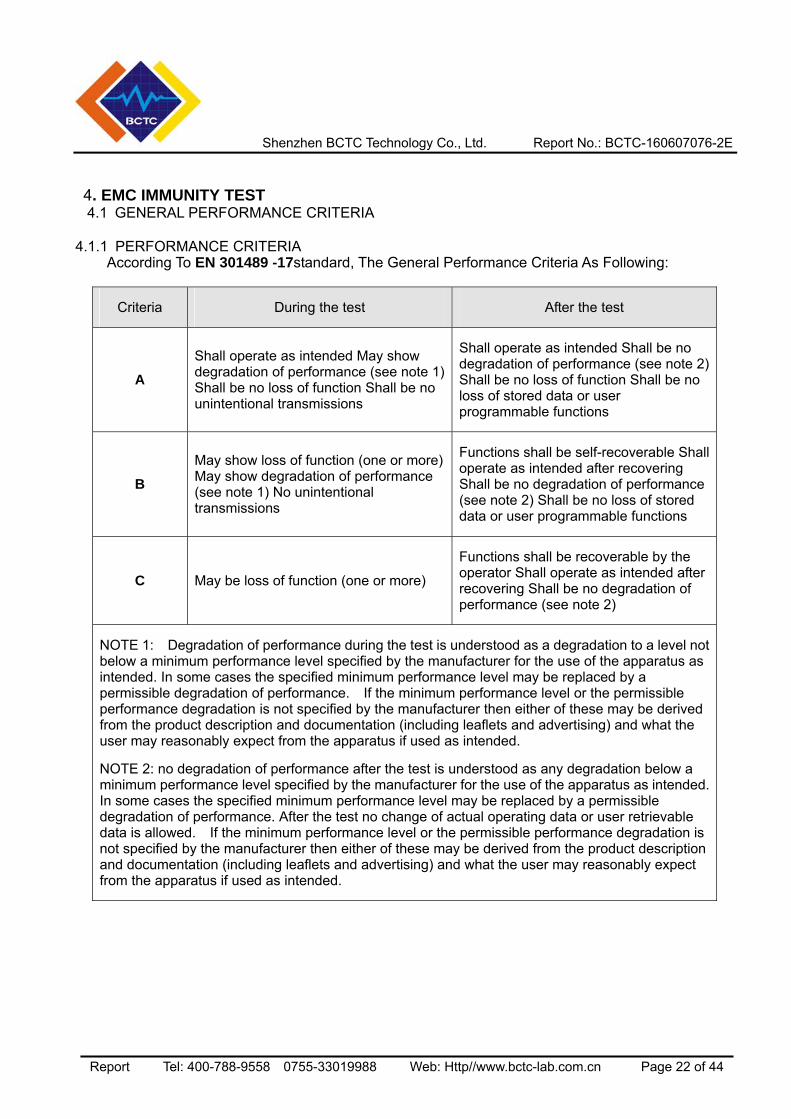
4.1.1 PERFORMANCE CRITERIA According To EN 301489 -17standard, The General Performance Criteria As Following:
Criteria During the test After the test
A Shall operate as intended May show degradation of performance (see note 1) Shall be no loss of function Shall be no unintentional transmissions
Shall operate as intended Shall be no degradation of performance (see note 2) Shall be no loss of function Shall be no loss of stored data or user programmable functions
B May show loss of function (one or more) May show degradation of performance (see note 1) No unintentional transmissions
Functions shall be self-recoverable Shall operate as intended after recovering Shall be no degradation of performance (see note 2) Shall be no loss of stored data or user programmable functions
C May be loss of function (one or more)
Functions shall be recoverable by the operator Shall operate as intended after recovering Shall be no degradation of performance (see note 2)
NOTE 1: Degradation of performance during the test is understood as a degradation to a level not below a minimum performance level specified by the manufacturer for the use of the apparatus as intended. In some cases the specified minimum performance level may be replaced by a permissible degradation of performance. If the minimum performance level or the permissible performance degradation is not specified by the manufacturer then either of these may be derived from the product description and documentation (including leaflets and advertising) and what the user may reasonably expect from the apparatus if used as intended.
NOTE 2: no degradation of performance after the test is understood as any degradation below a minimum performance level specified by the manufacturer for the use of the apparatus as intended. In some cases the specified minimum performance level may be replaced by a permissible degradation of performance. After the test no change of actual operating data or user retrievable data is allowed. If the minimum performance level or the permissible performance degradation is not specified by the manufacturer then either of these may be derived from the product description and documentation (including leaflets and advertising) and what the user may reasonably expect from the apparatus if used as intended.
Shenzhen BCTC Technology Co., Ltd. Report No.: BCTC-160607076-2E
Report Tel: 400-788-9558 0755-33019988 Web: Http//www.bctc-lab.com.cn Page 23 of 44
PERFORMANCE FOR TT
The performance criteria B shall apply, except for voltage dips of 100 ms and voltage interruptions of 5
000 ms duration, for which performance criteria C shall apply. Tests shall be repeated with the EUT in
standby mode (if applicable) to ensure that unintentional transmission does not occur. In systems using
acknowledgement signals, it is recognized that an acknowledgement (ACK) or not-acknowledgement
(NACK) transmission may occur, and steps should be taken to ensure that any transmission resulting
from the application of the test is correctly interpreted.
PERFORMANCE FOR TR
The performance criteria B shall apply, except for voltage dips of 100 ms and voltage interruptions of 5
000 ms duration for which performance criteria C shall apply. Where the EUT is a transceiver, under no
circumstances, shall the transmitter operate unintentionally during the test. In systems using
acknowledgement signals, it is recognized that an ACK or NACK transmission may occur, and steps
should be taken to ensure that any transmission resulting from the application of the test is correctly
interpreted.
PERFORMANCE FOR CT
The performance criteria A shall apply. Tests shall be repeated with the EUT in standby mode (if
applicable) to ensure that unintentional transmission does not occur. In systems using
acknowledgement signals, it is recognized that an Acknowledgement (ACK) or Not Acknowledgement
(NACK) transmission may occur, and steps should be taken to ensure that any transmission resulting
from the application of the test is correctly interpreted.
PERFORMANCE FOR CR
The performance criteria A shall apply. Where the EUT is a transceiver, under no circumstances, shall
the transmitter operate unintentionally during the test. In systems using acknowledgement signals, it is
recognized that an ACK or NACK transmission may occur, and steps should be taken to ensure that
any transmission resulting from the application of the test is correctly interpreted.
4.2 GENERAL PERFORMANCE CRITERIA TEST SETUP The EUT tested system was configured as the statements of 2.2 Unless otherwise a special operating condition is specified in the follows during the testing.
Shenzhen BCTC Technology Co., Ltd. Report No.: BCTC-160607076-2E
Report Tel: 400-788-9558 0755-33019988 Web: Http//www.bctc-lab.com.cn Page 24 of 44
4.3 ESD TESTING
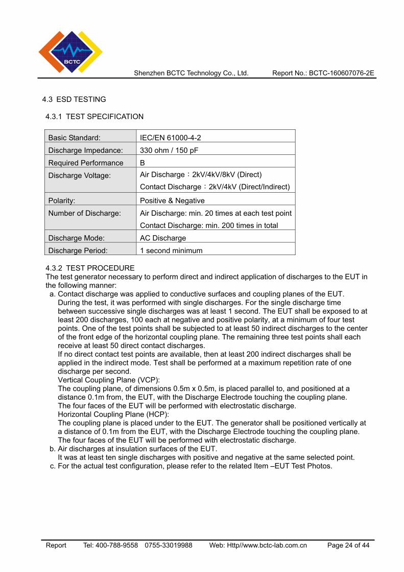
4.3.1 TEST SPECIFICATION
Basic Standard: IEC/EN 61000-4-2
Discharge Impedance: 330 ohm / 150 pF
Required Performance B
Discharge Voltage: Air Discharge:2kV/4kV/8kV (Direct) Contact Discharge:2kV/4kV (Direct/Indirect)
Polarity: Positive & Negative
Number of Discharge: Air Discharge: min. 20 times at each test point Contact Discharge: min. 200 times in total
Discharge Mode: AC Discharge
Discharge Period: 1 second minimum 4.3.2 TEST PROCEDURE The test generator necessary to perform direct and indirect application of discharges to the EUT in the following manner: a. Contact discharge was applied to conductive surfaces and coupling planes of the EUT.
During the test, it was performed with single discharges. For the single discharge time between successive single discharges was at least 1 second. The EUT shall be exposed to at least 200 discharges, 100 each at negative and positive polarity, at a minimum of four test points. One of the test points shall be subjected to at least 50 indirect discharges to the center of the front edge of the horizontal coupling plane. The remaining three test points shall each receive at least 50 direct contact discharges. If no direct contact test points are available, then at least 200 indirect discharges shall be applied in the indirect mode. Test shall be performed at a maximum repetition rate of one discharge per second. Vertical Coupling Plane (VCP): The coupling plane, of dimensions 0.5m x 0.5m, is placed parallel to, and positioned at a distance 0.1m from, the EUT, with the Discharge Electrode touching the coupling plane. The four faces of the EUT will be performed with electrostatic discharge. Horizontal Coupling Plane (HCP): The coupling plane is placed under to the EUT. The generator shall be positioned vertically at a distance of 0.1m from the EUT, with the Discharge Electrode touching the coupling plane. The four faces of the EUT will be performed with electrostatic discharge.
b. Air discharges at insulation surfaces of the EUT. It was at least ten single discharges with positive and negative at the same selected point.
c. For the actual test configuration, please refer to the related Item –EUT Test Photos.
Shenzhen BCTC Technology Co., Ltd. Report No.: BCTC-160607076-2E
Report Tel: 400-788-9558 0755-33019988 Web: Http//www.bctc-lab.com.cn Page 25 of 44
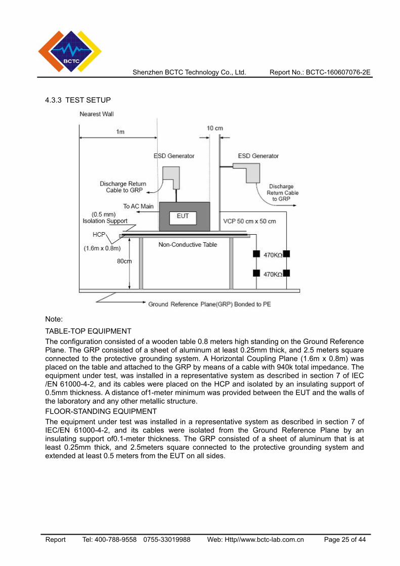
4.3.3 TEST SETUP
Note: TABLE-TOP EQUIPMENT The configuration consisted of a wooden table 0.8 meters high standing on the Ground Reference Plane. The GRP consisted of a sheet of aluminum at least 0.25mm thick, and 2.5 meters square connected to the protective grounding system. A Horizontal Coupling Plane (1.6m x 0.8m) was placed on the table and attached to the GRP by means of a cable with 940k total impedance. The equipment under test, was installed in a representative system as described in section 7 of IEC /EN 61000-4-2, and its cables were placed on the HCP and isolated by an insulating support of 0.5mm thickness. A distance of1-meter minimum was provided between the EUT and the walls of the laboratory and any other metallic structure. FLOOR-STANDING EQUIPMENT The equipment under test was installed in a representative system as described in section 7 of IEC/EN 61000-4-2, and its cables were isolated from the Ground Reference Plane by an insulating support of0.1-meter thickness. The GRP consisted of a sheet of aluminum that is at least 0.25mm thick, and 2.5meters square connected to the protective grounding system and extended at least 0.5 meters from the EUT on all sides.
Shenzhen BCTC Technology Co., Ltd. Report No.: BCTC-160607076-2E
Report Tel: 400-788-9558 0755-33019988 Web: Http//www.bctc-lab.com.cn Page 26 of 44
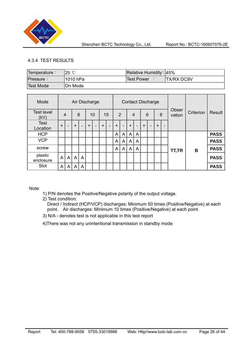
4.3.4 TEST RESULTS
Temperature: 25 Relative Humidity:45% Pressure: 1010 hPa Test Power : TX/RX DC9V Test Mode On Mode
Mode Air Discharge Contact Discharge
Test level (kV) 4 8 10 15 2 4 6 8
Test Location + - + - + - + - + - + - + - + -
Observation Criterion Result
HCP A A A A PASSVCP A A A A PASS
screw A A A A PASSplastic
enclosure A A A A PASS
Slot A A A A
TT,TR B
PASS
Note:
1) P/N denotes the Positive/Negative polarity of the output voltage.
2) Test condition: Direct / Indirect (HCP/VCP) discharges: Minimum 50 times (Positive/Negative) at each
point. Air discharges: Minimum 10 times (Positive/Negative) at each point. 3) N/A - denotes test is not applicable in this test report
4)There was not any unintentional transmission in standby mode
Shenzhen BCTC Technology Co., Ltd. Report No.: BCTC-160607076-2E
Report Tel: 400-788-9558 0755-33019988 Web: Http//www.bctc-lab.com.cn Page 27 of 44
4.4 RS TESTING
4.4.1 TEST SPECIFICATION
Basic Standard: IEC/EN 61000-4-3
Required Performance A
Frequency Range: 80 MHz - 1000 MHz ,1400MHz-2700MHz
Field Strength: 3 V/m
Modulation: 1kHz Sine Wave, 80%, AM Modulation
Frequency Step: 1 % of fundamental
Polarity of Antenna: Horizontal and Vertical
Test Distance: 3 m
Antenna Height: 1.5 m
Dwell Time: at least 3 seconds
4.4.2 TEST PROCEDURE The EUT and support equipment, which are placed on a table that is 0.8 meter above ground and the testing was performed in a fully-anechoic chamber. The testing distance from antenna to the EUT was 3 meters. The other condition as following manner: a. The field strength level was 3V/m. b. The frequency range is swept from 80 MHz to 1000 MHz, & 1400MHz - 2700MHz with the
signal 80%amplitude modulated with a 1kHz sine wave. The rate of sweep did not exceed 1.5x 10⁻³ decade/s. Where the frequency range is swept incrementally, the step size was 1% of fundamental.
c. Sweep Frequency 900 MHz, with the Duty Cycle:1/8 and Modulation: Pulse 217 Hz(if applicable)
d. The dwell time at each frequency shall be not less than the time necessary for the EUT to be able to respond.
e. The test was performed with the EUT exposed to both vertically and horizontally polarized fields on each of the four sides.
f. For the actual test configuration, please refer to the related Item –EUT Test Photos.
Shenzhen BCTC Technology Co., Ltd. Report No.: BCTC-160607076-2E
Report Tel: 400-788-9558 0755-33019988 Web: Http//www.bctc-lab.com.cn Page 28 of 44
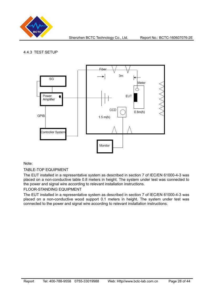
4.4.3 TEST SETUP
Note: TABLE-TOP EQUIPMENT The EUT installed in a representative system as described in section 7 of IEC/EN 61000-4-3 was placed on a non-conductive table 0.8 meters in height. The system under test was connected to the power and signal wire according to relevant installation instructions. FLOOR-STANDING EQUIPMENT The EUT installed in a representative system as described in section 7 of IEC/EN 61000-4-3 was placed on a non-conductive wood support 0.1 meters in height. The system under test was connected to the power and signal wire according to relevant installation instructions.
Shenzhen BCTC Technology Co., Ltd. Report No.: BCTC-160607076-2E
Report Tel: 400-788-9558 0755-33019988 Web: Http//www.bctc-lab.com.cn Page 29 of 44
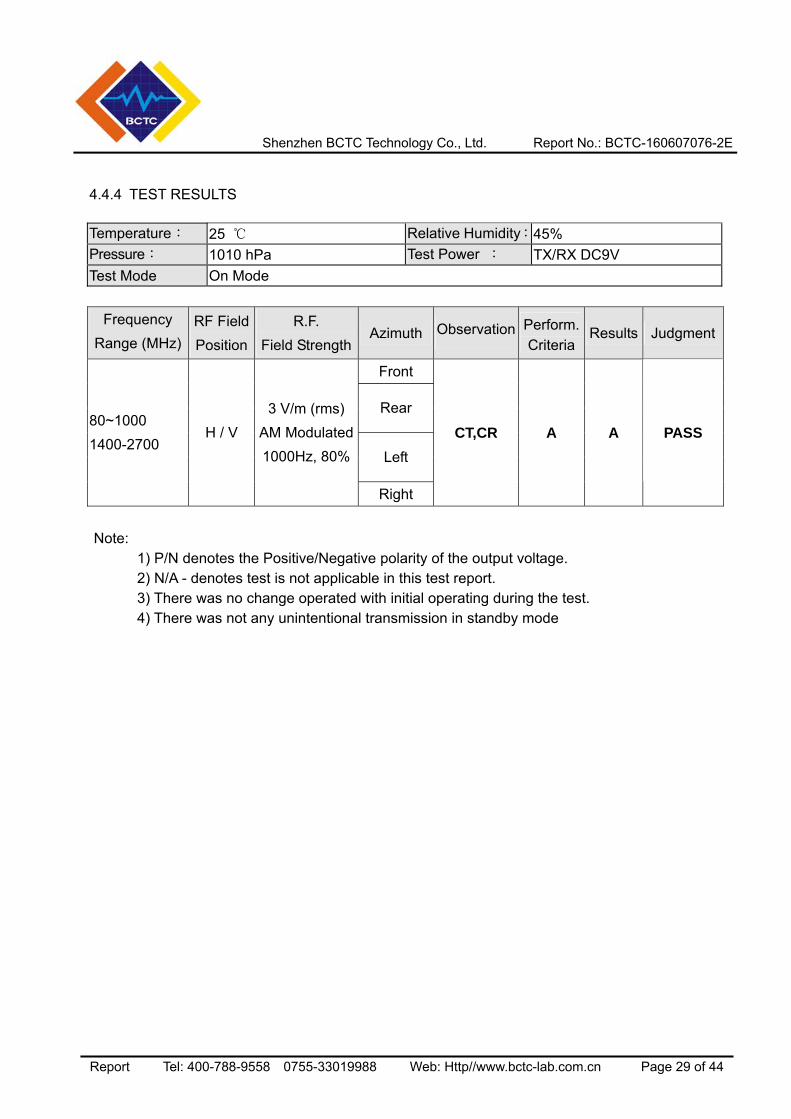
4.4.4 TEST RESULTS Temperature: 25 Relative Humidity:45% Pressure: 1010 hPa Test Power : TX/RX DC9V Test Mode On Mode
Frequency Range (MHz)
RF Field Position
R.F. Field Strength
Azimuth Observation Perform. Criteria
Results Judgment
Front
Rear
Left
80~1000 1400-2700
H / V 3 V/m (rms)
AM Modulated1000Hz, 80%
Right
CT,CR A A PASS
Note:
1) P/N denotes the Positive/Negative polarity of the output voltage. 2) N/A - denotes test is not applicable in this test report. 3) There was no change operated with initial operating during the test. 4) There was not any unintentional transmission in standby mode
Shenzhen BCTC Technology Co., Ltd. Report No.: BCTC-160607076-2E
Report Tel: 400-788-9558 0755-33019988 Web: Http//www.bctc-lab.com.cn Page 30 of 44
4.5 EFT/BURST TESTING
4.5.1 TEST SPECIFICATION
Basic Standard: IEC/EN 61000-4-4
Required Performance B
Test Voltage: Power Line:1 kV Signal/Control Line:0.5 KV
Polarity: Positive & Negative
Impulse Frequency: 5 kHz
Impulse Wave shape : 5/50 ns
Burst Duration: 15 ms
Burst Period: 300 ms
Test Duration: Not less than 1 min.
4.5.2 TEST PROCEDURE The EUT and support equipment, are placed on a table that is 0.8 meter above a metal ground plane measured 1m*1m min. and 0.65mm thick min. The other condition as following manner: a. The length of power cord between the coupling device and the EUT should not exceed 1
meter. b. Both positive and negative polarity discharges were applied. c. The duration time of each test sequential was 1 minute d. For the actual test configuration, please refer to the related Item –EUT Test Photos.
Shenzhen BCTC Technology Co., Ltd. Report No.: BCTC-160607076-2E
Report Tel: 400-788-9558 0755-33019988 Web: Http//www.bctc-lab.com.cn Page 31 of 44
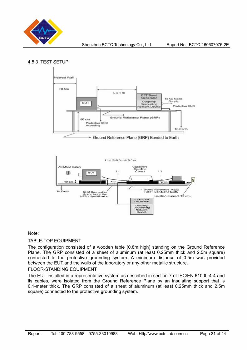
4.5.3 TEST SETUP
Note: TABLE-TOP EQUIPMENT The configuration consisted of a wooden table (0.8m high) standing on the Ground Reference Plane. The GRP consisted of a sheet of aluminum (at least 0.25mm thick and 2.5m square) connected to the protective grounding system. A minimum distance of 0.5m was provided between the EUT and the walls of the laboratory or any other metallic structure. FLOOR-STANDING EQUIPMENT The EUT installed in a representative system as described in section 7 of IEC/EN 61000-4-4 and its cables, were isolated from the Ground Reference Plane by an insulating support that is 0.1-meter thick. The GRP consisted of a sheet of aluminum (at least 0.25mm thick and 2.5m square) connected to the protective grounding system.
Shenzhen BCTC Technology Co., Ltd. Report No.: BCTC-160607076-2E
Report Tel: 400-788-9558 0755-33019988 Web: Http//www.bctc-lab.com.cn Page 32 of 44
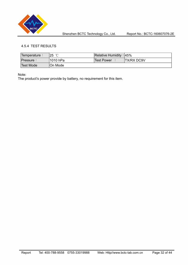
4.5.4 TEST RESULTS Temperature: 25 Relative Humidity:45% Pressure: 1010 hPa Test Power : TX/RX DC9V Test Mode On Mode
Note: The product’s power provide by battery, no requirement for this item.
Shenzhen BCTC Technology Co., Ltd. Report No.: BCTC-160607076-2E
Report Tel: 400-788-9558 0755-33019988 Web: Http//www.bctc-lab.com.cn Page 33 of 44
4.6 SURGE TESTING
4.6.1 TEST SPECIFICATION
Basic Standard: IEC/EN 61000-4-5
Required Performance B
Wave-Shape: Combination Wave 1.2/50 us Open Circuit Voltage 8 /20 us Short Circuit Current
Test Voltage: Power Line:0.5 kV, 1 kV, 2 kV
Surge Input/Output: L1-L2, L1-PE, L2-PE
Generator Source: 2 ohm between networks
Impedance: 12 ohm between network and ground
Polarity: Positive/Negative
Phase Angle: 0 /90/180/270
Pulse Repetition Rate: 1 time / min. (maximum)
Number of Tests: 5 positive and 5 negative at selected points
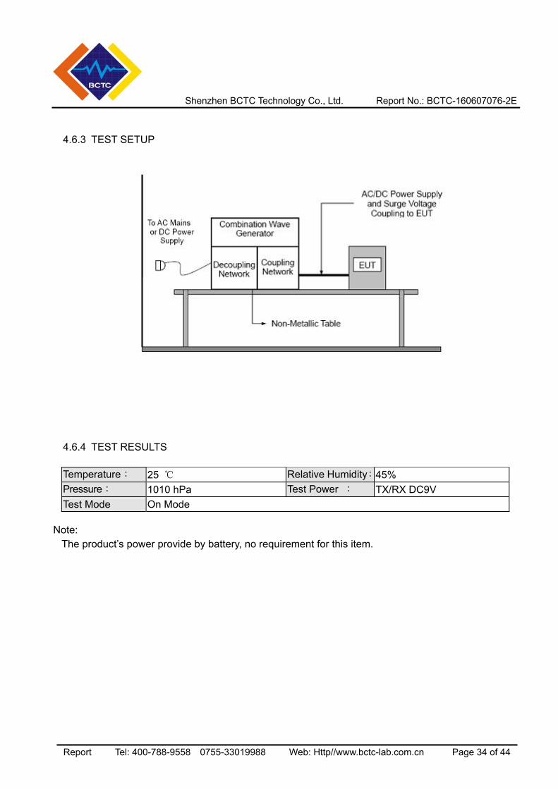
4.6.2 TEST PROCEDURE a. For EUT power supply:
The surge is to be applied to the EUT power supply terminals via the capacitive coupling network. Decoupling networks are required in order to avoid possible adverse effects on equipment not under test that may be powered by the same lines, and to provide sufficient decoupling impedance to the surge wave. The power cord between the EUT and the coupling/decoupling networks shall be 2meters in length (or shorter).
b. For test applied to unshielded unsymmetrically operated interconnection lines of EUT: The surge is applied to the lines via the capacitive coupling. The coupling /decoupling networks shall not influence the specified functional conditions of the EUT. The interconnection line between the EUT and the coupling/decoupling networks shall be 2 meters in length (or shorter).
c. For test applied to unshielded symmetrically operated interconnection /telecommunication lines of EUT: The surge is applied to the lines via gas arrestors coupling. Test levels below the ignition point of the coupling arrestor cannot be specified. The interconnection line between the EUT and the coupling/decoupling networks shall be 2 meters in length (or shorter).
d. For the actual test configuration, please refer to the related Item –EUT Test Photos.
Shenzhen BCTC Technology Co., Ltd. Report No.: BCTC-160607076-2E
Report Tel: 400-788-9558 0755-33019988 Web: Http//www.bctc-lab.com.cn Page 34 of 44
4.6.3 TEST SETUP
4.6.4 TEST RESULTS Temperature: 25 Relative Humidity:45% Pressure: 1010 hPa Test Power : TX/RX DC9V Test Mode On Mode
Note:
The product’s power provide by battery, no requirement for this item.
Shenzhen BCTC Technology Co., Ltd. Report No.: BCTC-160607076-2E
Report Tel: 400-788-9558 0755-33019988 Web: Http//www.bctc-lab.com.cn Page 35 of 44
4.7 INJECTION CURRENT TESTING
4.7.1 TEST SPECIFICATION
Basic Standard: IEC/EN 61000-4-6
Required Performance A
Frequency Range: 0.15 MHz - 80 MHz
Field Strength: 3 Vr.m.s.
Modulation: 1kHz Sine Wave, 80%, AM Modulation
Frequency Step: 1 % of fundamental
Dwell Time: at least 3 seconds
4.7.2 TEST PROCEDURE The EUT and support equipment, are placed on a table that is 0.8 meter above a metal ground plane measured 1m*1m min. and 0.65mm thick min. The other condition as following manner: a. The field strength level was 3V. b. The frequency range is swept from 150 KHz to 80 MHz, with the signal 80%amplitude
modulated with a 1kHz sine wave. The rate of sweep did not exceed 1.5x 10⁻³ decade/s. Where the frequency range is swept incrementally, the step size was 1% of fundamental.
c. The dwell time at each frequency shall be not less than the time necessary for the EUT to be able to respond.
d. For the actual test configuration, please refer to the related Item –EUT Test Photos.
Shenzhen BCTC Technology Co., Ltd. Report No.: BCTC-160607076-2E
Report Tel: 400-788-9558 0755-33019988 Web: Http//www.bctc-lab.com.cn Page 36 of 44
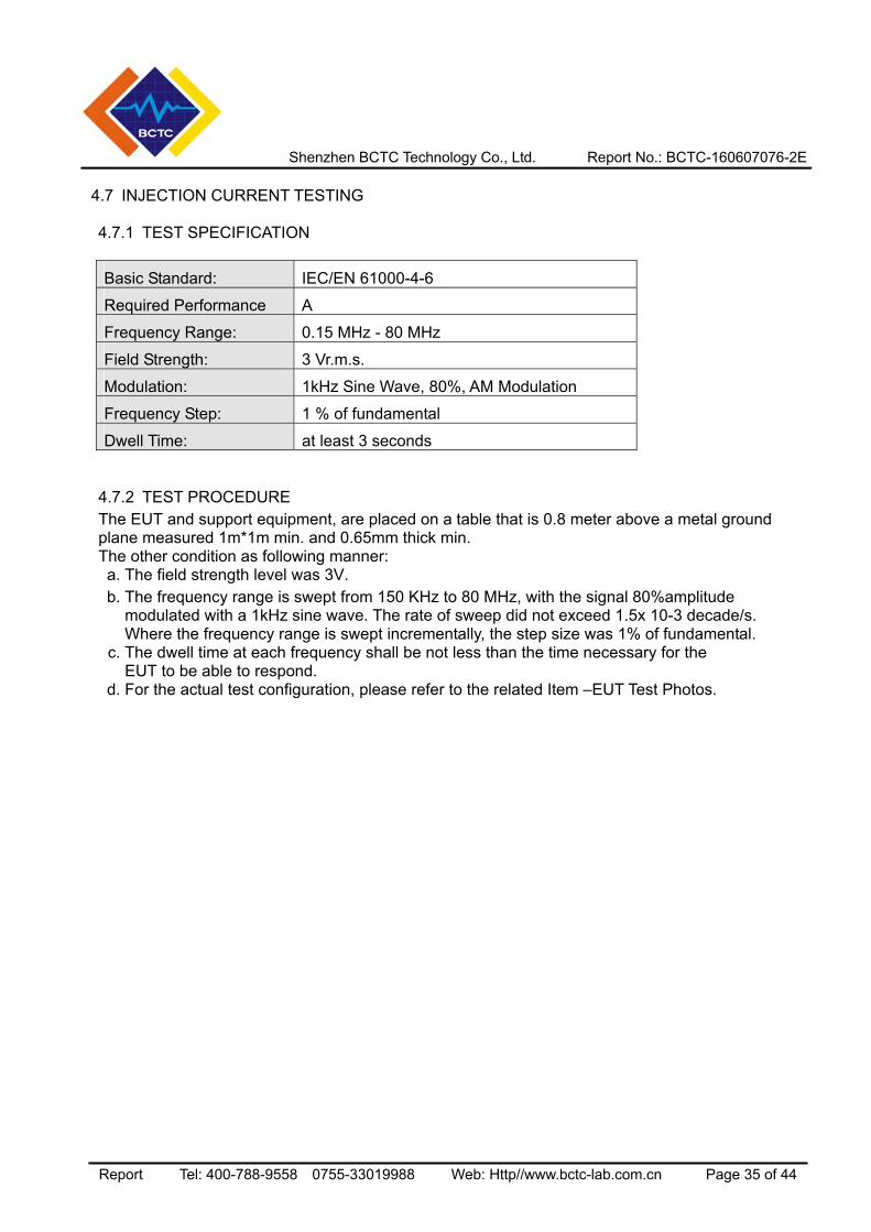
4.7.3 TEST SETUP
For the actual test configuration, please refer to the related Item –EUT Test Photos. NOTE: FLOOR-STANDING EQUIPMENT The equipment to be tested is placed on an insulating support of 0.1 meters height above a ground reference plane. All relevant cables shall be provided with the appropriate coupling and decoupling devices at a distance between 0.1 meters and 0.3 meters from the projected geometry of the EUT on the ground reference plane.
4.7.4 TEST RESULTS Temperature: 25 Relative Humidity:45% Pressure: 1010 hPa Test Power : TX/RX DC9V Test Mode On Mode
Note:
The product’s power provide by battery, no requirement for this item.
Shenzhen BCTC Technology Co., Ltd. Report No.: BCTC-160607076-2E
Report Tel: 400-788-9558 0755-33019988 Web: Http//www.bctc-lab.com.cn Page 37 of 44
4.8 VOLTAGE INTERRUPTION/DIPS TESTING
4.8.1 TEST SPECIFICATION
Basic Standard: IEC/EN 61000-4-11
Required Performance 100% reduction, 0.5 Cycle 100% reduction, 1.0 Cycle
30% reduction, 25 Cycles Voltage Interruptions: 100% reduction, 250 Cycles
Test Duration Time: Minimum three test events in sequence
Interval between Event: Minimum ten seconds
Phase Angle: 0°/45°/90°/135°/180°/225°/270°/315°/360°
Test Cycle: 3 times
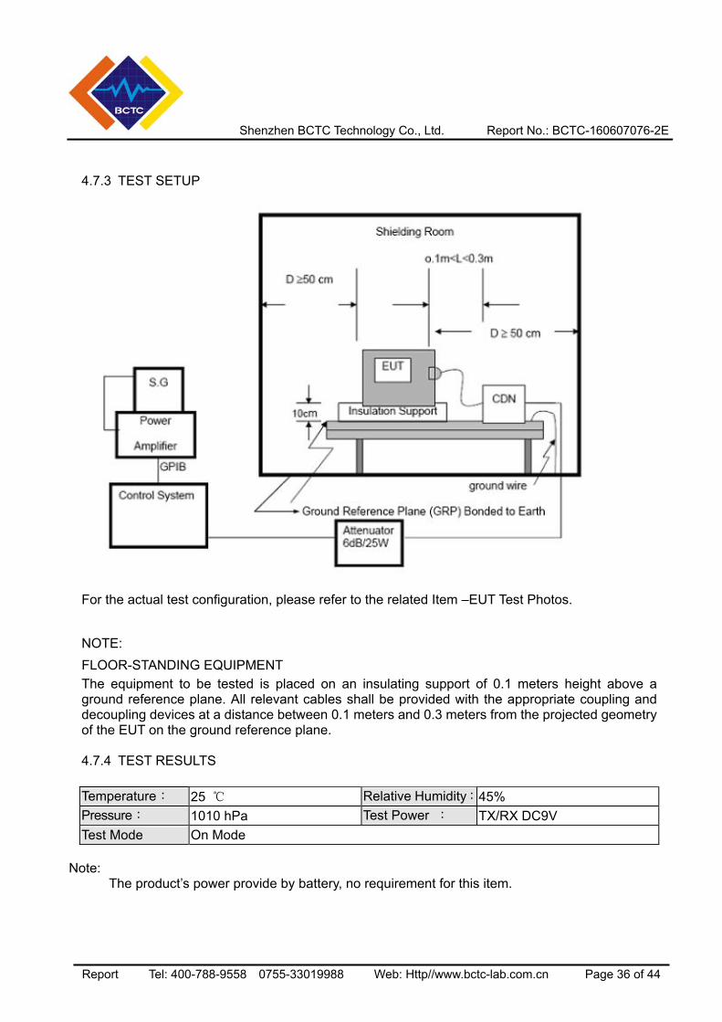
4.8.2 TEST PROCEDURE The EUT shall be tested for each selected combination of test levels and duration with a sequence of three dips/interruptions with intervals of 10 s minimum (between each test event). Each representative mode of operation shall be tested. Abrupt changes in supply voltage shall occur at zero crossings of the voltage waveform.
4.8.3 TEST SETUP
For the actual test configuration, please refer to the related Item –EUT Test Photos.
Shenzhen BCTC Technology Co., Ltd. Report No.: BCTC-160607076-2E
Report Tel: 400-788-9558 0755-33019988 Web: Http//www.bctc-lab.com.cn Page 38 of 44
4.8.4 TEST RESULTS
Temperature: 25 Relative Humidity:45% Pressure: 1010 hPa Test Power : TX/RX DC9V Test Mode On Mode
Note:
The product’s power provide by battery, no requirement for this item.
Shenzhen BCTC Technology Co., Ltd. Report No.: BCTC-160607076-2E
Report Tel: 400-788-9558 0755-33019988 Web: Http//www.bctc-lab.com.cn Page 39 of 44
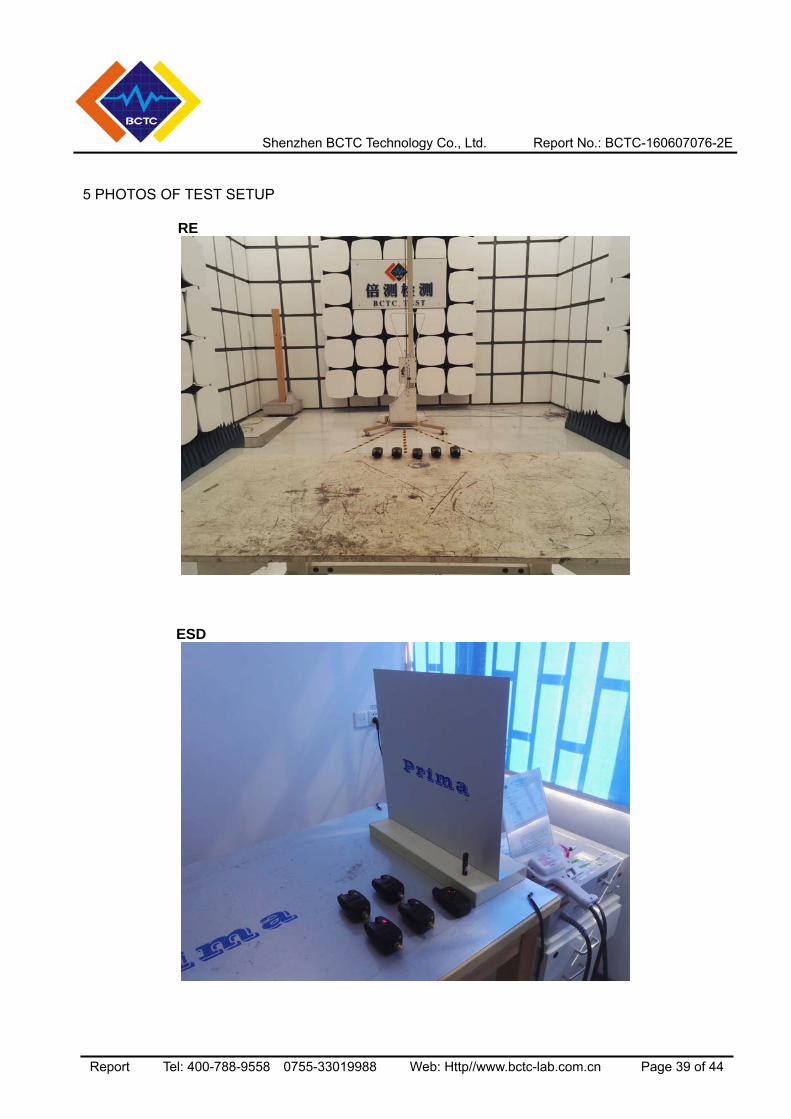
5 PHOTOS OF TEST SETUP
RE
ESD
Shenzhen BCTC Technology Co., Ltd. Report No.: BCTC-160607076-2E
Report Tel: 400-788-9558 0755-33019988 Web: Http//www.bctc-lab.com.cn Page 40 of 44
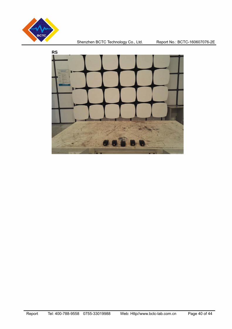
RS
Shenzhen BCTC Technology Co., Ltd. Report No.: BCTC-160607076-2E
Report Tel: 400-788-9558 0755-33019988 Web: Http//www.bctc-lab.com.cn Page 41 of 44
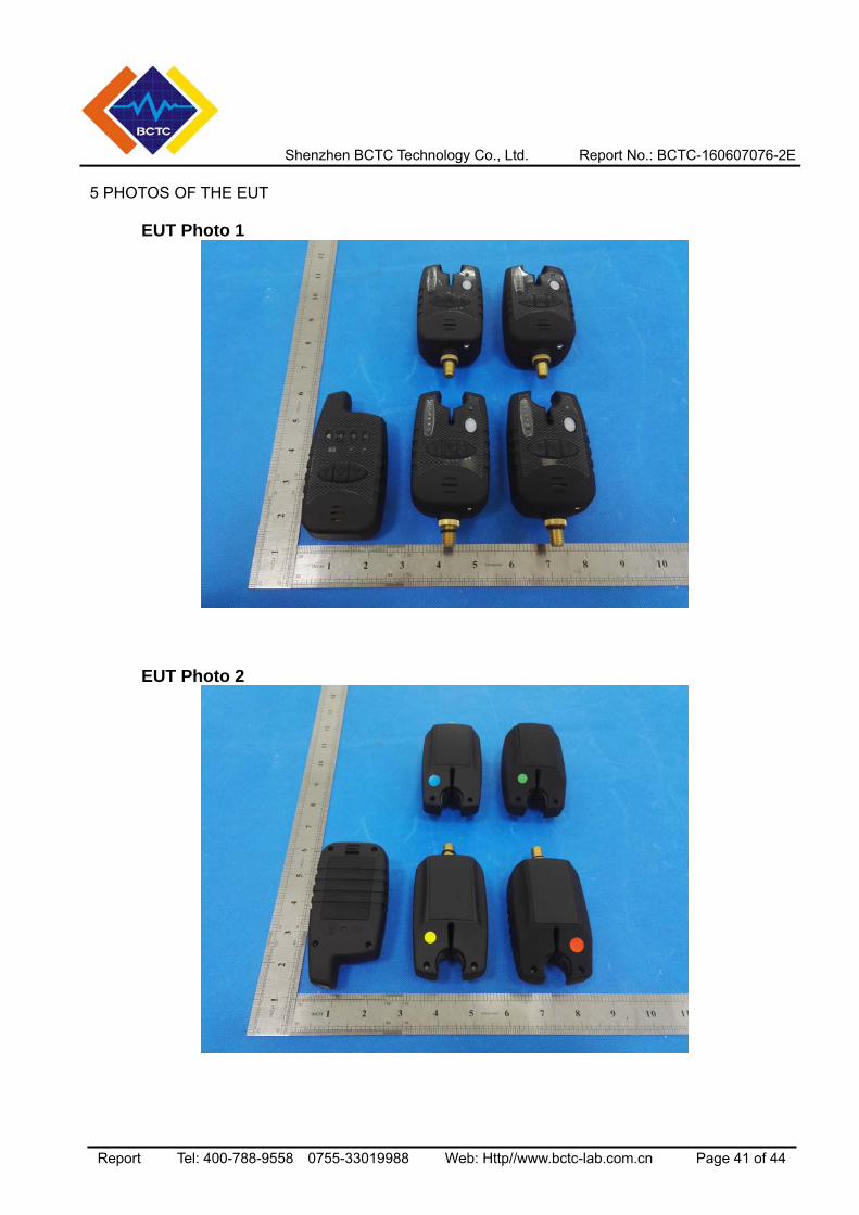
5 PHOTOS OF THE EUT
EUT Photo 1
EUT Photo 2
Shenzhen BCTC Technology Co., Ltd. Report No.: BCTC-160607076-2E
Report Tel: 400-788-9558 0755-33019988 Web: Http//www.bctc-lab.com.cn Page 42 of 44
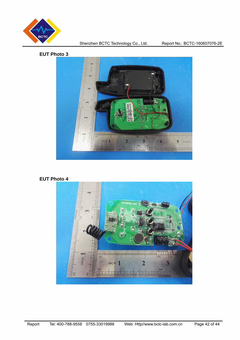
EUT Photo 3
EUT Photo 4
Shenzhen BCTC Technology Co., Ltd. Report No.: BCTC-160607076-2E
Report Tel: 400-788-9558 0755-33019988 Web: Http//www.bctc-lab.com.cn Page 43 of 44
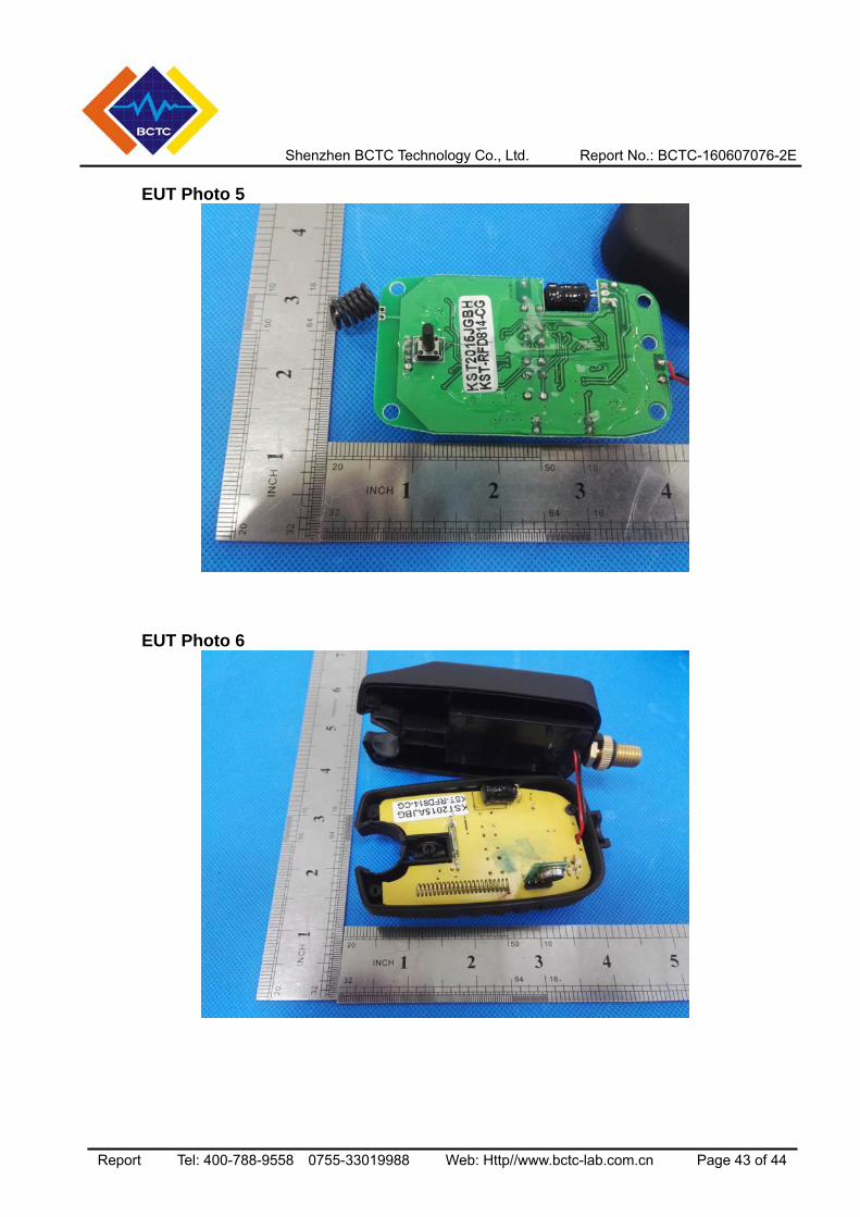
EUT Photo 5
EUT Photo 6
Shenzhen BCTC Technology Co., Ltd. Report No.: BCTC-160607076-2E
Report Tel: 400-788-9558 0755-33019988 Web: Http//www.bctc-lab.com.cn Page 44 of 44
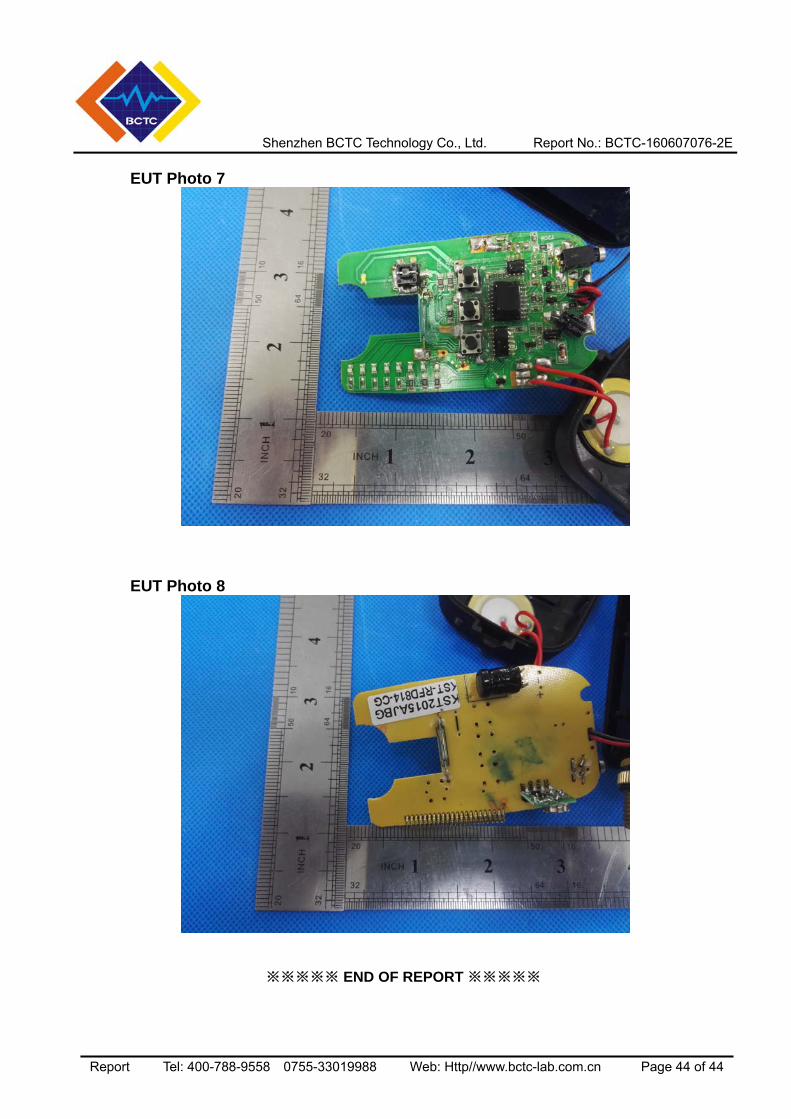
EUT Photo 7
EUT Photo 8
※※※※※ END OF REPORT ※※※※※