CE 221: MECHANICS OF SOLIDS I CHAPTER 1: … of Module • Mechanics of Solids • Introduction to...
42
CE 221: MECHANICS OF SOLIDS I CHAPTER 1: STRESS By Dr. Krisada Chaiyasarn Department of Civil Engineering, Faculty of Engineering Thammasat university
-
Upload
vuongduong -
Category
Documents
-
view
233 -
download
0
Transcript of CE 221: MECHANICS OF SOLIDS I CHAPTER 1: … of Module • Mechanics of Solids • Introduction to...

CE 221: MECHANICS OF SOLIDS I CHAPTER 1: STRESS By Dr. Krisada Chaiyasarn Department of Civil Engineering, Faculty of Engineering Thammasat university

Agenda • Introduction to your lecturer • Introduction to the Module • Chapter 1 Lecture coverage

Course Instructor • Dr. Krisada Chaiyasarn(PhD, Cambridge)
• Lecturer • Thammasat University Engineering School, Thailand
• Work Experience • J.P.Morgan, UK, IB Technology, Electronic Market Maker Developer • Ministry of Mobility and Public Works Belgium, Engineering Consultant • ITM Soil, Engineering Consultant
• Contact • Email: [email protected] • Website: www.krisadachaiyasarn.org

Introduction to the Module • Overview of Module
• What can you expect?
• Learning Objectives • How will you benefit?
• Learning Strategy • How you will learn?
• Assessment Overview • How you will be tested?
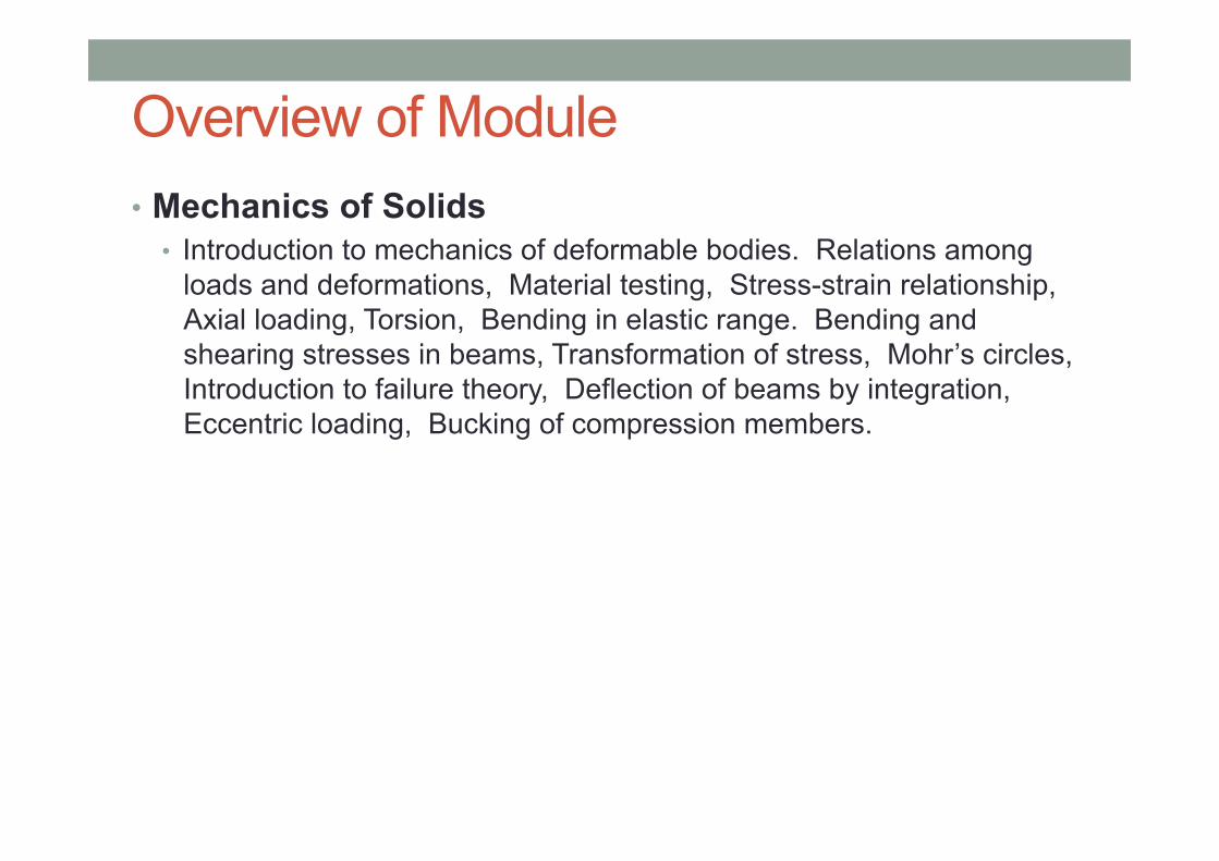
Overview of Module • Mechanics of Solids
• Introduction to mechanics of deformable bodies. Relations among loads and deformations, Material testing, Stress-strain relationship, Axial loading, Torsion, Bending in elastic range. Bending and shearing stresses in beams, Transformation of stress, Mohr’s circles, Introduction to failure theory, Deflection of beams by integration, Eccentric loading, Bucking of compression members.

Learning Objectives • Students are expected to:
• be able to explain mechanics of a deformable body loaded by applied forces, such as axial load, torsion, bending, and shear.
• be able to determine the responses of the deformable body, for examples, support reactions, internal forces in the body, and deformation, and be able to solve practical problems.
• be able to determine load-carrying capacity of simple structures, such as axially loaded members, shaft, and column, and be able to make a proper design of these structures as well.

Learning Strategy • Taught over 1 semester • Total 15 weeks of class covering 10 chapters • Each chapter consists of
• Lectures: Knowledge, theory and example • Additional examples in supplementary • Homeworks
• Total of 2 quiz

Course Overview • CHAPTER 1 STRESS • CHAPTER 2 STRAIN • CHAPTER 3 MECHANICAL PROPERTIES OF MATERIALS • CHAPTER 4 AXIAL LOAD • CHAPTER 5 TORSION • CHAPTER 6 BENDING
• CHAPTER 7 TRANSVERSE SHEAR • • CHAPTER 8 COMBINED LOADINGS • CHAPTER 9 DEFLECTIONS OF BEAMS • CHAPTER 10 BUCKLING OF COLUMNS

Prerequisite • Free-body diagrams, • Equilibrium of forces, • Bending moment diagram and Shear force diagram, • Cross-sectional properties of members such as Centroid
and Moment of inertia.
• You have already learned this in CE202

References • Main Textbook
• Hibbeler, R.C., (2004/200x). Mechanics of Materials (SI Edition). Prentice Hall, Singapore. Third/xx Edition.
• Any edition will do • All slides and diagrams are taken from this book.

Assessment Details • 4 Components from 100% • Quiz 5%
• 2 quiz will be given
• Attendance 5% • Random check
• Mid-term 35% • Chapter 1-5
• Final 55%, Chapter 6-10 • Chapter 6-10

Grading
Range of Marks
Grade Remarks
80 - 100 A Excellent: outstanding performance with only minor errors
70 - 79 B/B+ Very Good: above the average standard but with some errors
60 - 69 C/C+ Good: generally sound work with a number of notable errors
50 - 59 D/D+ Satisfactory: fair but with significant shortcomings
> 40 F Fail: performance does not meet the minimum criteria and considerable further work is required

Further Information • All details are summarized in Course Outline
• All materials can be download on • www.krisadadachaiyasarn.org

Any Questions

Outline • Introduction to simple stresses • Average normal stress in axial bar • Average shear stress • Bearing stress • Allowable stress • Designs of simple connections

Introduction • Mechanics of solids
• Studies the internal effects of stress and strain in a solid body subjected to an external loading
• Stress is the strengths of material • Strain is a measure of deformation
• All engineering designs are based on this subject.
• Historically, • 17th century Galileo experimented the effects of loads on rods and beams
on various materials. • 18th century, more material testing, notably, Saint-Venant, Poisson, Lame
and Navier
• Most fundamental problems have been solved, more advanced and complex problems, ongoingly • Theory of elasticity • Theory of plasticity

Equilibrium of a Deformable Body • This is the review of CE202 – Statics
• The knowledge of Free-body diagram is essential
• Free body diagram consists of • External loads • Support Reactions
• Then, use equilibrium equations to solve for all unknown forces
• Then, we will look at equilibrium using the internal forces

External Loads • Surface Forces
• Forces applied directly on the object, i.e. wind load
• Forces due to contact with another surface • Two types,
• concentrated force – force applied over a small area, e.g. a force acting from a ground on wheels
• distributed force – force applied over a larger area, can be idealised as linear distributed load, equivalent resultant force is used for analysis, e.g. loading along the length of a beam
• E.g. friction, reaction force
• Body Forces • Force exerting on another body without a direct
physical contact between bodies, e.g. gravity (i.e. weight), electromagnetic field

Support Reactions • Surface forces at the supports

Equilibrium equations

Internal Forces • Internal forces must exist within a body for equilibrium • Found by making a cut through a body • Exact distribution of internal force is unknown • But the internal force can be represented by equivalent
resultant force FR and equivalent resultant moment MR acting on point O (normally a centroid)
• The area along the cut is normally referred as cross-section

Internal Forces – 3D • Normal force, N, acts perpendicular to the area • Shear Force, V, acts along a plane, causing two segments
to slide over one another • Torsional Moment or torque, T, tend to twist one segment of
the body about an axis perpendicular to the area • Bending moment, M, tend to bend the body about an axis
lying within the plane of the area

Internal Forces – 2D • Normal force, N, acts perpendicular to the area • Shear Force, V, acts along a plane, causing two segments
to slide over one another, just one force • Bending moment, M, tend to bend the body about an axis
lying within the plane of the area

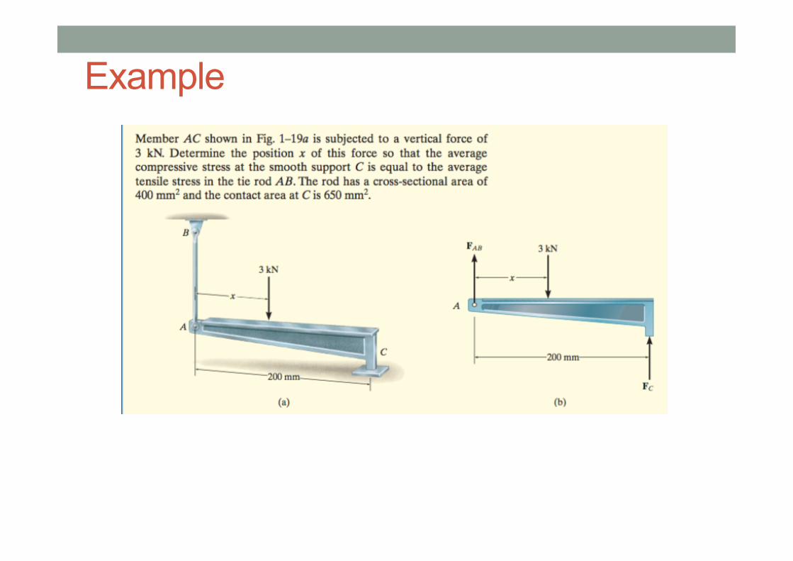
Example

Example

Stress • MRo and FR are the resultant effects acting
at O on the sectioned area • We want to find the actual distribution of
loading of the resultant effects in order to find stress
• To find a distribution, we reduce the size of an area to ΔA towards zeros, two assumptions, • Material is continuous, i.e. no voids • Cohesive, i.e. all portions are connected, no
cracks, or separations • A finite force ΔF is acting on the area, and
have x, y and z force components as shown, ΔFx, ΔFy, and ΔFz
respectively • As ΔA approaches zero, so as ΔF, the
quotient is called stress

Normal Stress • Stress is the intensity of the internal force acting on a specific plane • Normal Stress, σ, is the intensity of the force acting normal to ΔA
• Pulling force generates tensile stress, pushing force generate compressive stress

Shear Stress • The intensity of force acting tangent to ΔA, use symbol τ • The subscript indicates the axes along which each shear stress acts

General State of Stress • If the body is further sectioned by planes x-z and y-z, then a cubic
volume element of material represents the state of stress • Stress has unit N/m2 or Pa (Pascal),

Average Normal Stress in axially loaded bar • Assuming the bar is homogeneous and isotropic, then the bar will
deform uniformly • Homogeneous material has the same physical and mechanical
properties throughout the volume • Isotropic material has the same properties in all directions, e.g. steel • Since the material is uniform, it is subjected to a constant normal stress
distribution

Average Normal Stress in axially loaded bar • P passes through the centroid, hence zero moments
• Only a normal stress exists on any small volume of material located at each point on the cross section, consider equilibrium
• Hence two normal stress components on an element are equal but opposite in direction, this is termed uniaxial stress
• P is equivalent to the volume under the stress diagram, P = σA

Maximum Average Normal Stress • When there are changes in cross-section or change of normal force, the
stress will change • Hence, we need to find the ratio P/A, to determine the location of the
maximum normal stress. • Hence we need to plot the normal force diagram, i.e. the diagram to
show variations of P along the bar at any point x • The sign convention is + for tension and - for compression

Example
Example

Average Shear Stress
• Stress component acts in the plane of the sectioned area
• From the diagram, if F is large enough, it will fail along the plane AB and CD
• From equilibrium V = F/2 • The average shear stress distributed over
each sectioned area is
• The shear stress has the same direction as V • Actual distribution of the shear stress is
higher, but this value is generally acceptable.

Shear Stress Equilibrium • Shear stress in an element must be in equilibrium, in both force and
moment equilibrium. Hence it requires all other shear stress to meet the conditions.

Shear Stress Equilibrium • All four shear stresses must has equal magnitude and be directed
either toward or away from each other at opposite edges of the element, this is pure shear

Example

Allowable Stress
• Factor of safety is a ratio of the failure load and the allowable load to ensure a margin to prevent structural failure

Design of a Simple Connections
• The area of the member are used to help achieve the allowable stress to comply with the safety factor

Example

Example


![Mechanics of Solids [3 1 0 4] CIE 101 / 102 First Year B.E ...icasfiles.com/mechanics of solids/notes/slides/1... · Mechanics of Solids PART-I PART-II Mechanics of Deformable Bodies](https://static.fdocuments.in/doc/165x107/60e4e466746b7501e128b225/mechanics-of-solids-3-1-0-4-cie-101-102-first-year-be-of-solidsnotesslides1.jpg)