CE-071 Activated Sludge Wastewater Treatment
36
PDH Star | T / F: (833) PDH‐STAR (734‐7827) | E: [email protected] CE‐071 Activated Sludge Wastewater Treatment Instructor: J Paul Guyer, P.E., R.A. Course ID: CE‐071 PDH Hours: 2 PDH
Transcript of CE-071 Activated Sludge Wastewater Treatment
PDH Star | T / F: (833) PDH‐STAR (734‐7827) | E: [email protected]
CE‐071 Activated Sludge Wastewater Treatment Instructor: J Paul Guyer, P.E., R.A. Course ID: CE‐071 PDH Hours: 2 PDH
J. Paul Guyer, P.E., R.A. Editor Paul Guyer is a registered civil engineer, mechanical engineer, fire protection engineer and architect with 35 years of experience designing buildings and related infrastructure. For an additional 9 years he was a principal staff advisor to the California Legislature on capital outlay and infrastructure issues. He is a graduate of Stanford University and has held numerous national, state and local offices with the American Society of Civil Engineers, Architectural Engineering Institute and National Society of Professional Engineers. He is a Fellow of ASCE, AEI and CABE (U.K.).
An Introduction to Activated Sludge Wastewater Treatment
An Introduction to Activated Sludge
Wastewater Treatment
J. Paul Guyer, P.E., R.A.
Editor
The Clubhouse Press El Macero, California
CONTENTS
1. INTRODUCTION
2. ACTIVATED SLUDGE PROCESSES
3. CLOSED-LOOP REACTOR DESIGN CRITERIA
4. EXAMPLE CALCULATIONS
5. REFERENCES
6. BIBLIOGRAPHY
(This publication is adapted from the Unified Facilities Criteria of the United States government which are in the public domain, have been authorized for unlimited distribution, and are not copyrighted.)
© J. Paul Guyer 2018 1
1. GENERAL CONSIDERATIONS. The activated sludge process has been employed
extensively throughout the world in its conventional form and modified forms, all of
which are capable of meeting secondary treatment effluent limits. This publication
presents the different modifications of the conventional activated sludge process,
including general bases for design, methods of aeration, and design factors for aeration
tanks, final sedimentation units and sludge handling systems. Figures 1 through 4 are
schematic diagrams of the conventional and modified processes. The characteristics
and obtainable removal efficiencies for these processes are listed in table 3. All
designed processes will include preliminary treatment consisting of bar screen as a
minimum and, as needed, comminutor, grit chamber, and oil and grease removal units.
© J. Paul Guyer 2018 2
2. ACTIVATED SLUDGE PROCESSES
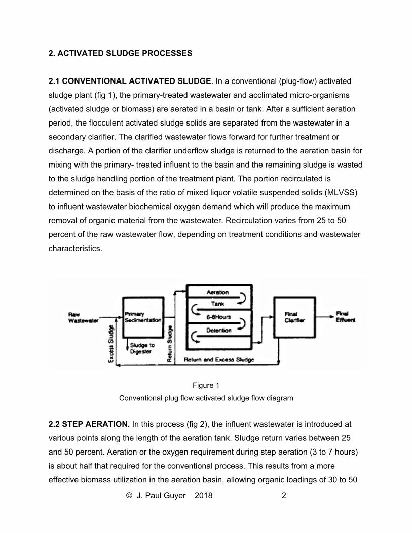
2.1 CONVENTIONAL ACTIVATED SLUDGE. In a conventional (plug-flow) activated
sludge plant (fig 1), the primary-treated wastewater and acclimated micro-organisms
(activated sludge or biomass) are aerated in a basin or tank. After a sufficient aeration
period, the flocculent activated sludge solids are separated from the wastewater in a
secondary clarifier. The clarified wastewater flows forward for further treatment or
discharge. A portion of the clarifier underflow sludge is returned to the aeration basin for
mixing with the primary- treated influent to the basin and the remaining sludge is wasted
to the sludge handling portion of the treatment plant. The portion recirculated is
determined on the basis of the ratio of mixed liquor volatile suspended solids (MLVSS)
to influent wastewater biochemical oxygen demand which will produce the maximum
removal of organic material from the wastewater. Recirculation varies from 25 to 50
percent of the raw wastewater flow, depending on treatment conditions and wastewater
characteristics.
Figure 1
Conventional plug flow activated sludge flow diagram
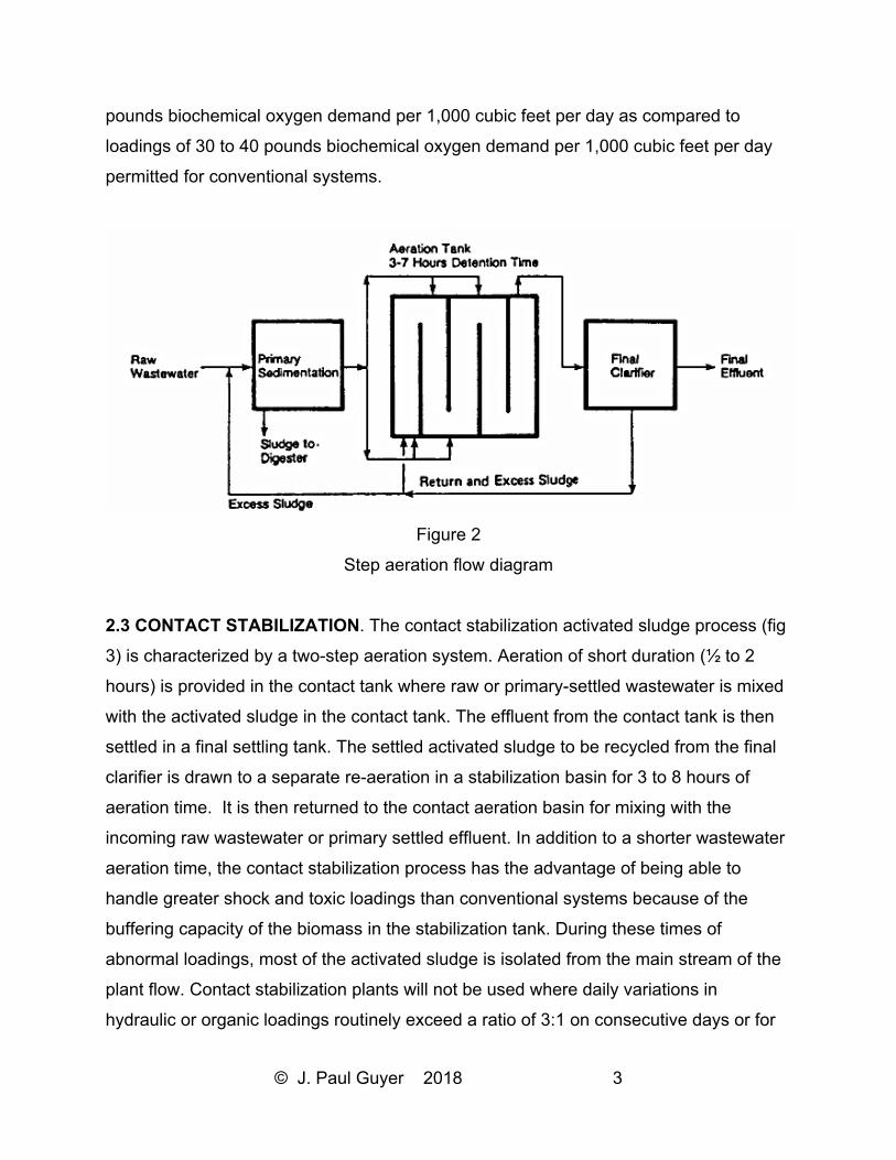
2.2 STEP AERATION. In this process (fig 2), the influent wastewater is introduced at
various points along the length of the aeration tank. Sludge return varies between 25
and 50 percent. Aeration or the oxygen requirement during step aeration (3 to 7 hours)
is about half that required for the conventional process. This results from a more
effective biomass utilization in the aeration basin, allowing organic loadings of 30 to 50
© J. Paul Guyer 2018 3
pounds biochemical oxygen demand per 1,000 cubic feet per day as compared to
loadings of 30 to 40 pounds biochemical oxygen demand per 1,000 cubic feet per day
permitted for conventional systems.
Figure 2
Step aeration flow diagram
2.3 CONTACT STABILIZATION. The contact stabilization activated sludge process (fig
3) is characterized by a two-step aeration system. Aeration of short duration (½ to 2
hours) is provided in the contact tank where raw or primary-settled wastewater is mixed
with the activated sludge in the contact tank. The effluent from the contact tank is then
settled in a final settling tank. The settled activated sludge to be recycled from the final
clarifier is drawn to a separate re-aeration in a stabilization basin for 3 to 8 hours of
aeration time. It is then returned to the contact aeration basin for mixing with the
incoming raw wastewater or primary settled effluent. In addition to a shorter wastewater
aeration time, the contact stabilization process has the advantage of being able to
handle greater shock and toxic loadings than conventional systems because of the
buffering capacity of the biomass in the stabilization tank. During these times of
abnormal loadings, most of the activated sludge is isolated from the main stream of the
plant flow. Contact stabilization plants will not be used where daily variations in
hydraulic or organic loadings routinely exceed a ratio of 3:1 on consecutive days or for
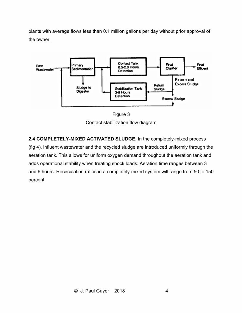
© J. Paul Guyer 2018 4
plants with average flows less than 0.1 million gallons per day without prior approval of
the owner.
Figure 3
Contact stabilization flow diagram
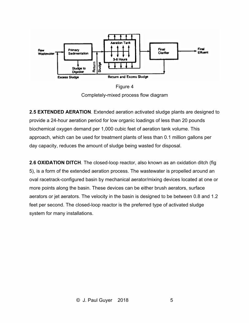
2.4 COMPLETELY-MIXED ACTIVATED SLUDGE. In the completely-mixed process
(fig 4), influent wastewater and the recycled sludge are introduced uniformly through the
aeration tank. This allows for uniform oxygen demand throughout the aeration tank and
adds operational stability when treating shock loads. Aeration time ranges between 3
and 6 hours. Recirculation ratios in a completely-mixed system will range from 50 to 150
percent.
© J. Paul Guyer 2018 5
Figure 4
Completely-mixed process flow diagram
2.5 EXTENDED AERATION. Extended aeration activated sludge plants are designed to
provide a 24-hour aeration period for low organic loadings of less than 20 pounds
biochemical oxygen demand per 1,000 cubic feet of aeration tank volume. This
approach, which can be used for treatment plants of less than 0.1 million gallons per
day capacity, reduces the amount of sludge being wasted for disposal.
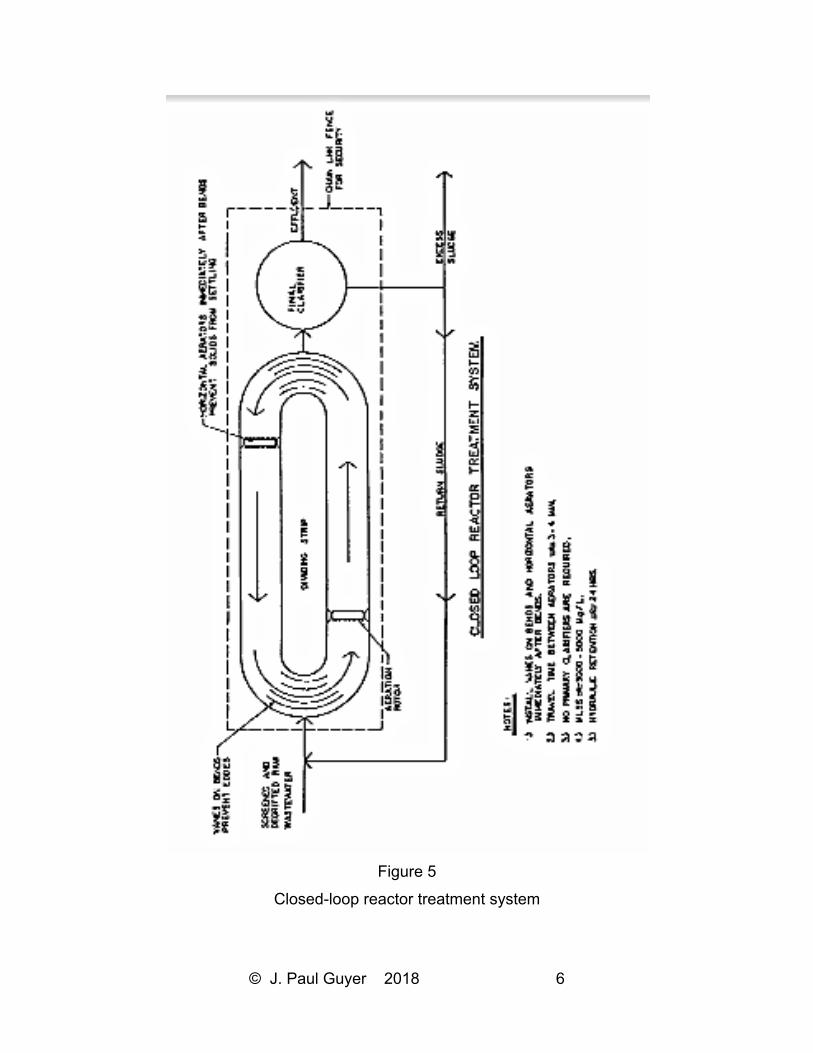
2.6 OXIDATION DITCH. The closed-loop reactor, also known as an oxidation ditch (fig
5), is a form of the extended aeration process. The wastewater is propelled around an
oval racetrack-configured basin by mechanical aerator/mixing devices located at one or
more points along the basin. These devices can be either brush aerators, surface
aerators or jet aerators. The velocity in the basin is designed to be between 0.8 and 1.2
feet per second. The closed-loop reactor is the preferred type of activated sludge
system for many installations.
© J. Paul Guyer 2018 6
Figure 5
Closed-loop reactor treatment system
© J. Paul Guyer 2018 7
3. CLOSED-LOOP REACTOR DESIGN CRITERIA
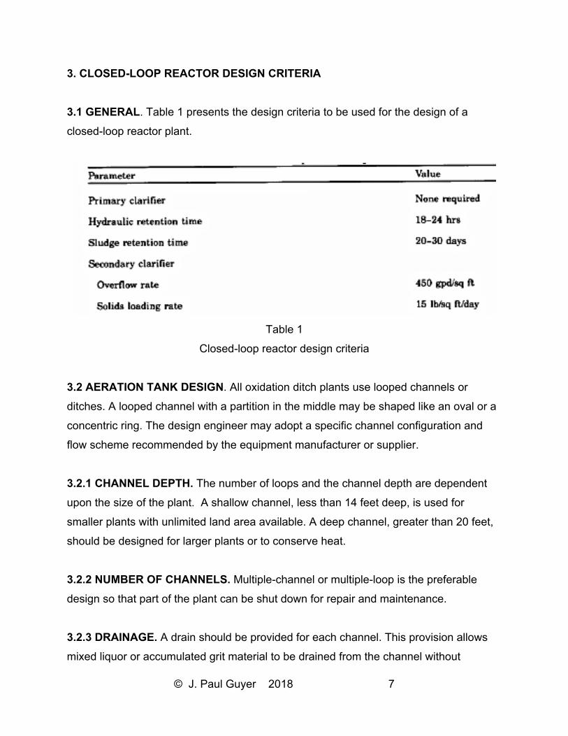
3.1 GENERAL. Table 1 presents the design criteria to be used for the design of a
closed-loop reactor plant.
Table 1
Closed-loop reactor design criteria
3.2 AERATION TANK DESIGN. All oxidation ditch plants use looped channels or
ditches. A looped channel with a partition in the middle may be shaped like an oval or a
concentric ring. The design engineer may adopt a specific channel configuration and
flow scheme recommended by the equipment manufacturer or supplier.
3.2.1 CHANNEL DEPTH. The number of loops and the channel depth are dependent
upon the size of the plant. A shallow channel, less than 14 feet deep, is used for
smaller plants with unlimited land area available. A deep channel, greater than 20 feet,
should be designed for larger plants or to conserve heat.
3.2.2 NUMBER OF CHANNELS. Multiple-channel or multiple-loop is the preferable
design so that part of the plant can be shut down for repair and maintenance.
3.2.3 DRAINAGE. A drain should be provided for each channel. This provision allows
mixed liquor or accumulated grit material to be drained from the channel without
© J. Paul Guyer 2018 8
expensive pumping. Many oxidation ditch plants do not have drains in their channels
and are having maintenance problems.
3.2.4 CHANNEL LINING. Deep channels are to be built exclusively with reinforced
concrete. A concrete liner can be placed against the earth backing in shallow channels
by pouring concrete or gunite (shotcrete) to a thickness of 3 to 4 inches. The concrete
or gunite should provide a minimum compressive strength of 3,000 pounds per square
inch in 28 days.
3.3 AERATION. Depending on the width and depth of the channel, various types of
aerators can meet the oxygenation and mixing requirements.
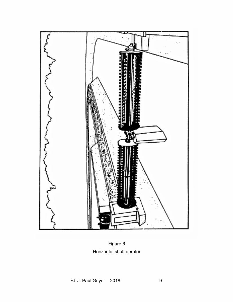
3.3.1 ROTOR AERATOR. A rotor aerator is a horizontal shaft with protruding blades
which rotates, thereby transferring oxygen into the wastewater and propelling it around
the ditch. Figure 6 illustrates a typical horizontal-shaft aerator. The minimum length of
shaft is 3 feet; the maximum length of shaft is 30 feet. This type of aerator is suitable for
shallow channels.
3.3.2 INDUCTION AERATOR. This type of aerator, which is available in various sizes,
draws the mixed liquor and air down a U-tube and discharges it for a distance
downstream in the channel. Compressed air at low pressure can be injected near the
top of the down-draft tube to enhance oxygenation. A bulkhead (which should be
partially opened at the bottom) is required to separate the channel to maintain the flow
circulation. This type of aerator is suitable for shallow to moderately deep channels.
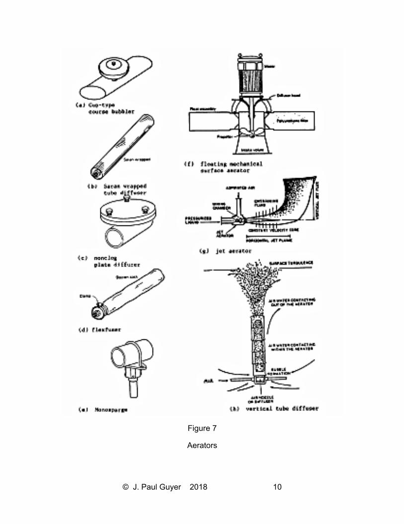
3.3.3 JET AERATION. Jet aeration is specifically designed for deep channels. Both air
and the mixed liquor are pressurized (by aspirator pumping) into a mixing chamber from
where the mixture is discharged as a jet stream into the surrounding channel liquid.
Deep channels are used to take advantage of better oxygen transfer. Figure 7 illustrates
a jet aerator, among various other types of aerators.
© J. Paul Guyer 2018 9
Figure 6
Horizontal shaft aerator
© J. Paul Guyer 2018 10
Figure 7
Aerators
© J. Paul Guyer 2018 11
3.3.4 DIFFUSED AERATION PLUS SLOW MIXER. This type of aeration is more
suitable for deep channels. Air bubbles are introduced into the mixed liquor through a
pipe grid system with diffusers to provide oxygenation while a slow propeller mixer
provides the flow circulation and mixing.
3.3.5 AERATOR SIZING. Aerators should be sized to provide adequate mixing and
oxygenation. However, the same size rotor provides different levels of mixing and
oxygenation depending on the degree of its submergence. First, the oxygen
requirement must be calculated for a level that will satisfy the carbonaceous
biochemical oxygen demand removal as well as nitrification-denitrification (if needed).
Oxidation ditch equipment manufacturers provide tables or charts for selecting the
aerator size for any given speed and submergence (immersion) based on the calculated
oxygen requirement. The aerator size should also be checked against the mixing
requirement set by the manufacturers. Preferably, more than one aerator should be
used per channel; they should be placed at different locations so that if one breaks
down, the channel will still function. The procedure for selecting the jet aerator size is
similar except there is no submergence factor. The sizing of the induction aerator and
the diffused air plus slow mixer units is not precise. Design data for these new aeration
systems are not yet available. One reason for this is that the amount of energy required
for mixing relative to the energy required for oxygenation is uncertain since it depends a
great deal on the channel geometry, which varies among plants. More testing data must
be collected before a design criterion can be established.
3.4 SLUDGE DEWATERING AND DISPOSAL. Sludge from oxidation ditch plants
operating in the extended aeration mode (sludge retention time of 20 to 30 days) can be
wasted directly to open drying beds. It can also be wasted directly to tank trucks which
spread the liquid sludge on the plant grounds or on adjacent land. The degree of sludge
stabilization in the oxidation ditch is equivalent to that of a conventional activated sludge
plant operated at a 10-day sludge retention time followed by aerobic digestion of the
sludge for 7 to 15 days. In most climates, 1.0 square foot of drying bed surface area per
population equivalent (0.17 pound biochemical oxygen demand per capita per day)
© J. Paul Guyer 2018 12
should be used. This capacity can accept 2.2 cubic feet of wasted sludge per 100 capita
per day, which is typical for domestic wastewater treatment. Double units of drying beds
should be used so that half of them can be taken out of service for maintenance.
3.5 COLD CLIMATE. In moderately cold areas, ice buildup on clarifier scum collection
boxes can cause problems and eventually jam the skimmer mechanisms. Therefore,
final clarifiers should be covered. In cold areas, the spray from surface aerators will
freeze on adjacent structures, bearings, gear reducers, etc., making maintenance
difficult. Drive components and walkways near the aerators should be covered to shield
them from spray, or mounted in isolated compartments. In very cold areas, heated
covers for surface aerators should be provided. Ice fences should be installed across
the channel upstream of brush-type aerators to prevent chunks of ice from breaking the
brushes.
© J. Paul Guyer 2018 13
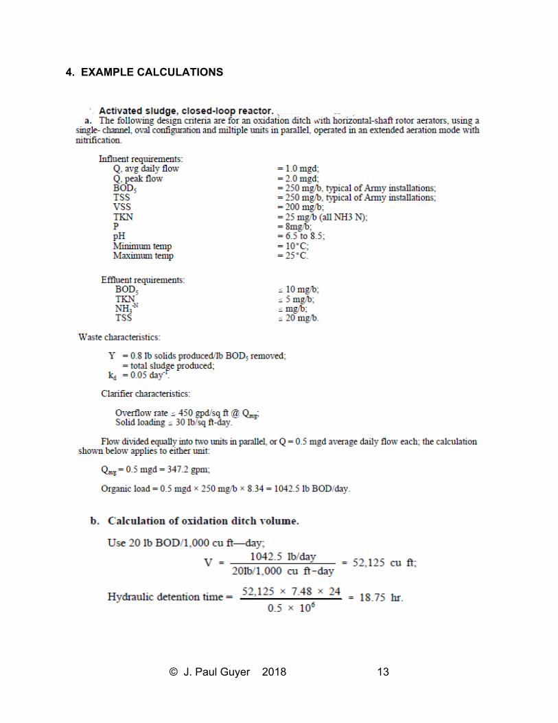
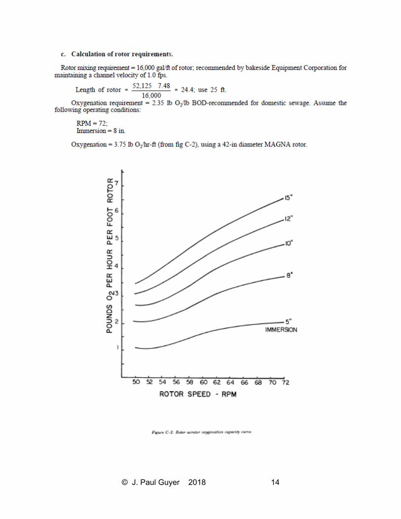
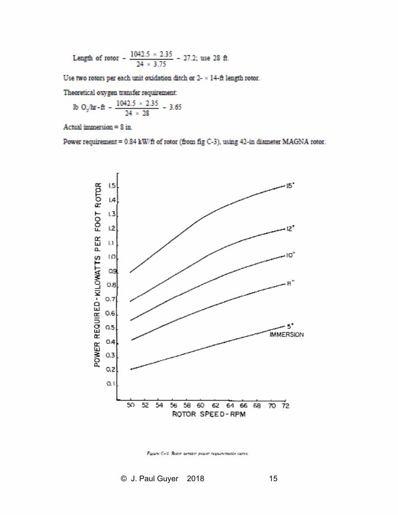
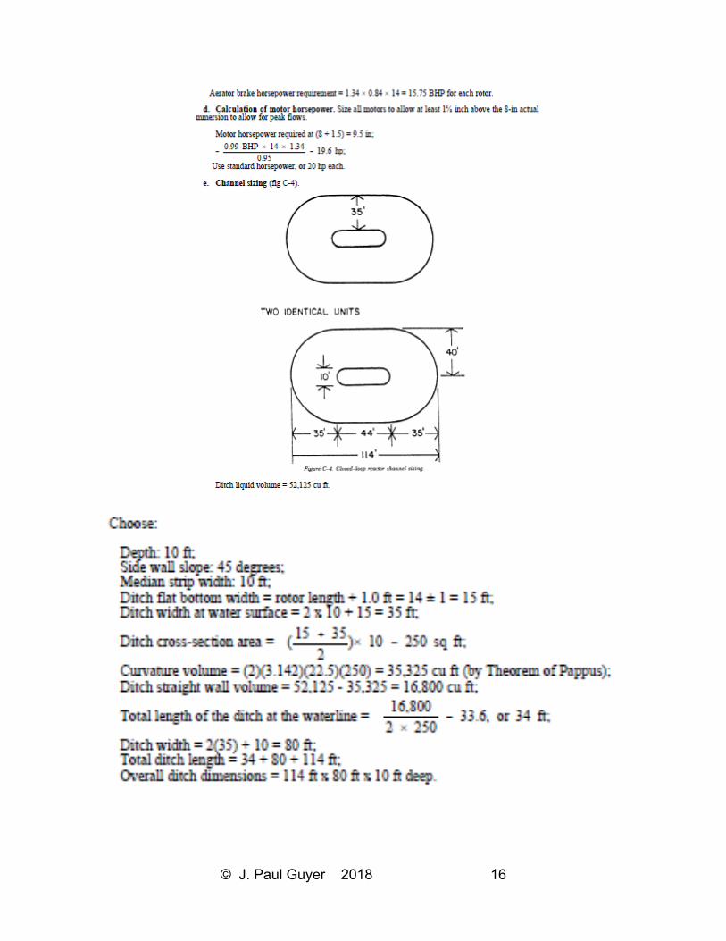
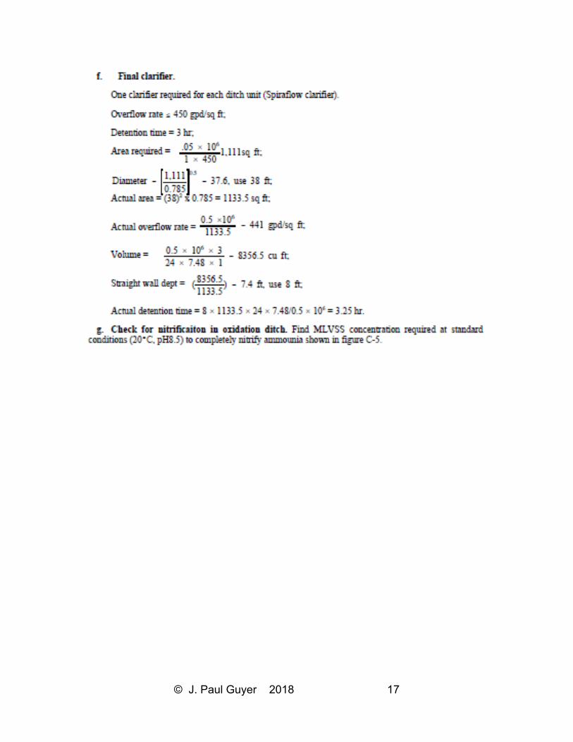
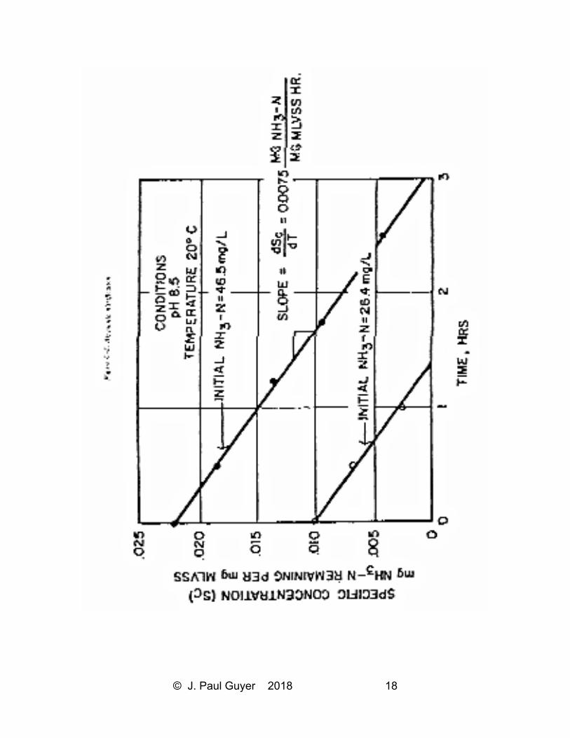
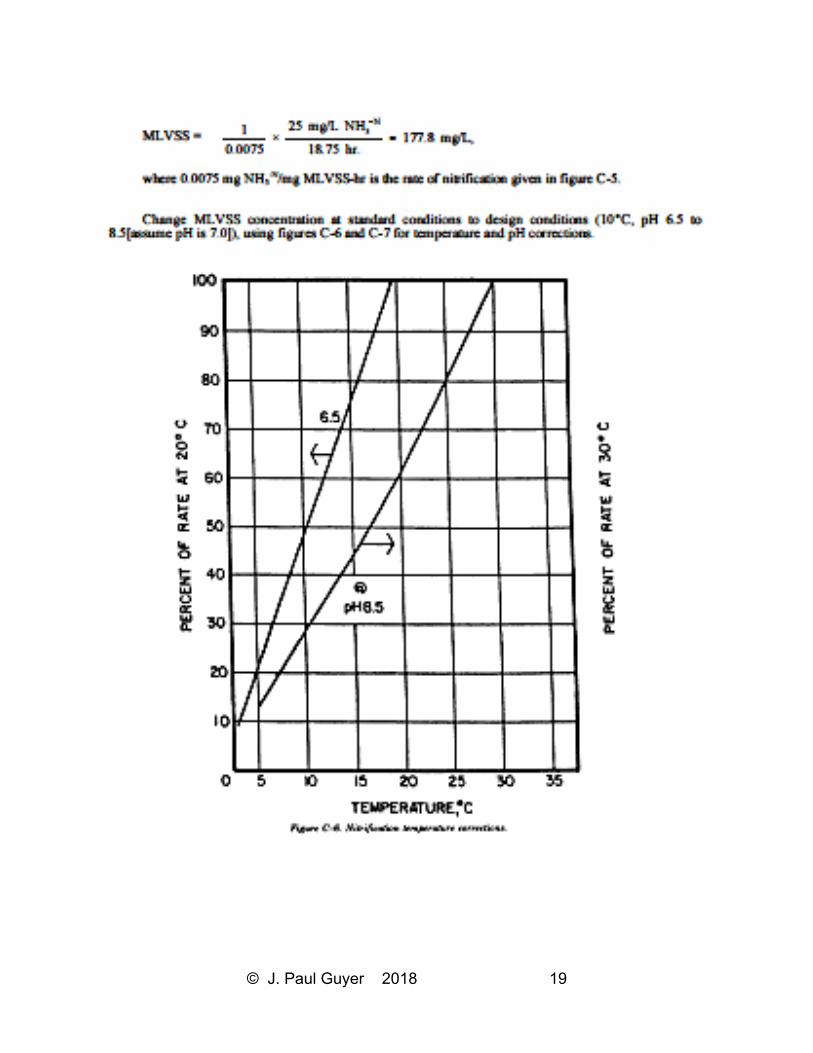
4. EXAMPLE CALCULATIONS
© J. Paul Guyer 2018 14
© J. Paul Guyer 2018 15
© J. Paul Guyer 2018 16
© J. Paul Guyer 2018 17
© J. Paul Guyer 2018 18
© J. Paul Guyer 2018 19
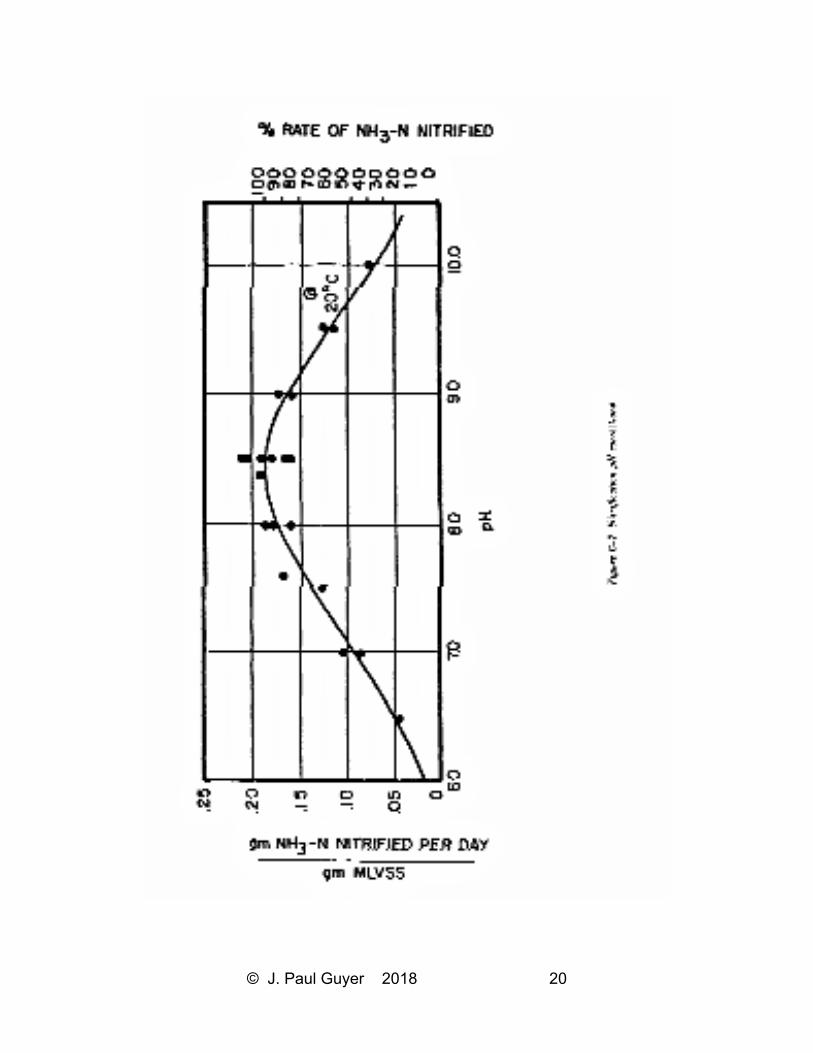
© J. Paul Guyer 2018 20
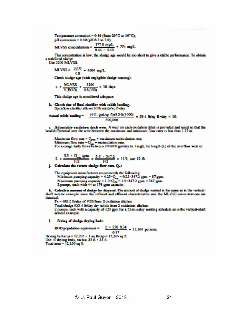
© J. Paul Guyer 2018 21
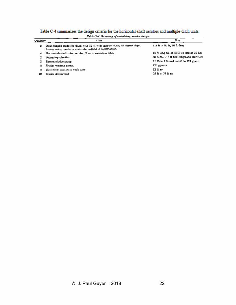
© J. Paul Guyer 2018 22
© J. Paul Guyer 2018 23
5. REFERENCES
5.1 GOVERNMENT PUBLICATIONS
PL 92-500 Federal Water Pollution Control Act
5.1.1 DEPARTMENT OF DEFENSE
AFM 88-15 Air Force Design Manual-Criteria and Standards for Air Force Construction
AFP 19-5 Environmental Quality Control Handbook: Industrial Wastes
AFR 19-1 Pollution Abatement and Environmental Quality
AR 200-1 Environmental Protection and Enhancement
TM 5-813-5/AFM 88-10, Vol.5 Water Supply Water Distribution Systems
TM 5-814-1/AFM 88-11, Vol.1 Sanitary and Industrial Waste Sewers
TM 5-814-2/AFM 88-11, Vol.2 Sanitary and Industrial Wastewater Collection—Pumping
Stations and Force Mains
TM 5-814-6 Industrial Wastes
TM 5-814-8 Evaluation Criteria Guide for Water Pollution: Prevention, Control, and
Abatement
TM 5-852-1/AFR 88-19, Vol.1 Arctic and Subarctic Construction: General Provisions
TM 5-852-4/AFM 88-19, Chap. 4 Arctic and Subarctic Construction: Building
Foundations
TM 5-852-5/AFR 88-19, Vol.5 Arctic and Subarctic Construction: Utilities
5.1.2 ENVIRONMENTAL PROTECTION AGENCY (EPA)
R-2-73-199 Application of Plastic Media Trickling Filters for Biological Nitrification
Systems
625/1-74-006 Process Design Manual for Sludge Treatment and Disposal (Oct 74)
625/1-75-003a Process Design Manual for Suspended Solids Removal (Jan 75)
625/1-76-001a Process Design Manual For Phosphorus Removal (Oct 71)
625/1-80-012 Process Design Manual for Onsite Wastewater Treatment and Disposal
Systems (Oct 80)
© J. Paul Guyer 2018 24
625/1-81-013 Process Design Manual for Land Treatment of Municipal Wastewater (Oct
81)
625/1-82-014 Process Design Manual for Dewatering Municipal Wastewater Sludges
(Oct 82)
625/1-83-015 Process Design Manual for Municipal Wastewater Stabilization Ponds
(Oct 83)
Process Design Manual for Carbon Absorbtion (Oct 73)
Process Design Manual for Nitrogen Control (Oct 75)
Process Design Manual for Upgrading Exist-Wastewater Treatment Plants (Oct 75)
Handbook for Monitoring Industrial Wastewater (Aug 73)
5.2 NON-GOVERNMENT PUBLICATIONS
5.2.1 AMERICAN WATERWORKS ASSOCIATION (AWWA)
6666 West Quincey Avenue, Denver CO 80235
Standard Methods for the Examination of Water and Wastewater
16th Edition, Franson, M.A. (ed), APHA, WPCF (1984)
Safety Practices for Water Utilities
5.2.2 WATER POLLUTION CONTROL FEDERATION (WPCF)
Manual of Practice No.1 Safety and Health in Wastewater Works (1983)
Manual of Practice No.8 Wastewater Treatment Plant Design (1977)
© J. Paul Guyer 2018 25
6. BIBLIOGRAPHY
Alter, A.J. Sewage and sewage disposal in cold regions. U.S. Army Cold Regions
Research and Engineering Laboratory. Monograph III-C5b, 106 pp, 1969.
Alter, A.J. Water supply in cold regions. Cold Regions Science and Engineering
Monograph III-C52. U.S. Army Cold Regions Research and Engineering Laboratory,
Honover NH, January, 1969.
American Society of Agricultural Engineers. On-Site Sewage Treatment, American
Society of Agricultural Engineers, Publication 1-82, St. Joseph MO 49085, 1984.
Babbitt, H.E. and Baumann, E.R., Sewerage and Sewage Treatment, New York: John
Wiley, 1958.
Bandy, J.T., Poon, C.PC., and Smith, E.D., Oxidation Ditch Technology for Upgrading
Army Sewage Treatment Facilities, 1983.
Barnes, D., Bliss, PJ., Gould, BW, and Vallentine, H.R., Water and Wastewater
Engineering Systems, Pitman Books Ltd., London, 1981.
Barnes, D., and Wilson, F., Design and Operation of Small Sewage Works, Halsted
Press, 1976.
Bitton, G., et al., Sludge: Health Risks of Land Application, Ann Arbor Science, 1980.
Borchardt, J.S., et al. (eds.), Sludge and Its Ultimate Disposal, Jones and Redman, Ann
Arbor Science, 1981.
© J. Paul Guyer 2018 26
Bouwer, H., Rice, R.C., and Escarcega, E.D., High-Rate Land Treatment I: Infiltration
and Hydraulic Aspects of the Flushing Meadow Project. Journal WPCF 46: 834-843,
1974.
Boyle, WC., and Otis, R.J., On-Site Treatment, Environmental Research Information
Center; Office of Research and Development, U.S. EPA, Cincinnati OH 45268, 1982.
Bruce, A.M., et at., Disinfection of Sludge: Technical, Economic and Microbiological
Aspects, D. Reidel Publishing Company, Dordrecht, Holland, 1980.
Chemical Engineering Catalog, Equipment and Materials for the Process Industries,
Reinhold Publishing Co., Stamford CT, 06904.
Cohen, S., and Wallman, H., Demonstration of Waste Flow Reduction from Households,
No. PB 236904/AS NTIS, Department of Commerce, Springfield VA 22151.
Culp, R.L., and Culp, G.L., Advanced Wastewater Treatment, Van Nostrand-Reinhold,
New York, 1971.
Curds, C.R., and Hawkes, H.A., Ecological Aspects of Used Water Treatment, Volume
1, Academic Press, 1975.
Deese, PL. and Hudson, J.F., Planning Wastewater Management Facilities for Small
Communities, Municipal Environmental Research Laboratory, Office of Research and
Development, U.S. EPA, Cincinnati OH 45268.
Diaper, E.W, Tertiary Treatment by Microstraining, Water and Sewage Works, June
1969.
Dinges, R., Natural Systems for Water Pollution Control, Environmental Engineers
Series, Van Nostrand- Reinhold, New York, 1984.
© J. Paul Guyer 2018 27
D’Itri, F.M., Land Treatment of Municipal Wastewater, Vegetation Selection and
Management, Ann Arbor Science, 1982.
D’Itri, F., et al., Municipal Wastewater in Agriculture, Academic Press, 1984.
Ehreth, D.J., and Basilico, JV., An Overview of Nitrogen Control Technology in
Municipal Wastewater Treatment, Technical Paper presented 4th Joint Chemical
Engineering Conference, Vancouver BC, Canada, 10 September 1973.
Eikum, A., Treatment of Septic Sludge-European Practice, Norwegian Institute for
Water Research, 0-80040, 1982.
Eikum, A.S., and Seabloom, RW, Alternative Wastewater Treatment, (Reidel-Holland),
Kluwer- Academic, 1982.
Fair, G.M., Geyer, J.C., and Okun, D.A., Water and Wastewater Engineering, John
Wiley, New York, 1966.
Fay, S.C., and Walke, R.H., The Composting Option for Human Waste Disposal in the
Backcountry, Forest Service Research Note NE-246, N.E. Forest Service, USDA, Upper
Darby PA 19082, 1975.
Ferguson, B.K., Landscape Hydrology: A Unified Guide to Water-Related Design, In the
Landscape: Critical Issues and Resources, Conference of Council on Education in
Landscape Architecture, Utah State University, Logan UT, 1980.
Gehm, HW, and Bregman, J.I., Handbook of Water Resources and Pollution Control,
Van Nostrand-Reinhold, New York, 1976.
© J. Paul Guyer 2018 28
Grady and Lim, Biological Wastewater Treatment: Theory and Applications, Pollution
Engineering and Technology Series: Volume 12, Dekker, 1985.
Harris, S.E., Reynolds, J.J., Hill, DW, Filip, D.S., and Middlebrooks, E.J., Intermittant
Sand Filtration for Upgrading Waste Stabilization Pond Effluents, JWPCF 49:83-102,
1977.
Hartenstein, R., and Mitchell, M.J., Utilization of Earthworms and Micro-organisms in
Stabilization and Detoxification of Residue Sludges from Treatment of Wastewaters,
NSF Report, Grant ENV-7-06994, 1978.
Howland, WE., Flow over Porous Media as in a Trickling Filter Proceedings in 12th
Purdue Industrial Waste Conference, pp.435-465, 1957.
Hutzler, N.J., Otis, R.J., and Boyle, WC., Field and Laboratory Studies of Onsite
Household Wastewater Treatment Alternatives, Proceedings of Ohio Home Sewage
Disposal Conference, Ohio State University, Columbus OH 1984.
Kardos, L.T., Sopper, WE., Myers, E.A., Parizek, R.R., and Nesbitt, J.B., Renovation of
Secondary Effluent for Re-use as a Water Resource, Office of Research and
Development, U.S. EPA, EPA-66012-74-016, 1974.
Kruse, CW, et al., Improvement in Terminal Disinfection of Sewage Effluents, Water &
Sewage Works, June 1973.
Liech, H., New Options for a Sewerless Society, Compost Science, Summer 1976.
Linell, K.A., and Johnston, G.H., Engineering Design and Construction in Permafrost
Regions: A Review, in North American Contribution, Permafrost: Second International
Conference, 19763, pp.553-575, National Academy of Sciences, Washington DC, 1973.
© J. Paul Guyer 2018 29
Lynam, B., et al., Tertiary Treatment at Metro Chicago by Means of Rapid Sand
Filtration and Microstrainers, WPCF Journal, February 1969.
Metcalf and Eddy, Inc., Wastewater Engineering, McGraw Hill, New York, 1972.
Michigan State University, Institute of Water Research, Utilization of Natural
Ecosystems for Wastewater Renovation, Final Report for Region V Office, U.S. EPA,
East Lansing MI, 1976.
National Research Council of Canada, Permafrost Engineering Design and
Construction, prepared by the Committee on Geotechnical Research, National
Research Council of Canada, John Wiley & Sons, New York, 1981.
Office of Appropriate Technology, Rural Wastewater Disposal Alternatives, Final Report
Phase I, State Water Resources Control Board, State of California, Governor’s Office of
Planning and Research, #750.
Otis, R.J., et al., U.S. Environmental Protection Agency, Alternatives for Small
Treatment Systems, Onsite Disposal/Septage Treatment and Disposal, U.S. EPA
Technology Transfer Seminar Publication 625/4-77-011, 1977.
Parker, HW, and Bregman, J.I., Wastewater Systems Engineering, Prentice-Hall,
Englewood Cliffs, 1975.
Parr, J.F., et al., Current Research on Composting of Sewage Sludge, Process
Conference on Utilization of Soil Organisms in Sludge Management, State University of
New York, Syracuse NY, 1982.
Rich, L.G., Low Maintenance, Mechanically Simple Wastewater Treatment Systems,
Water Resources and Environmental Engineering Series, McGraw-Hill, Hightstown NJ
08520, 1980.
© J. Paul Guyer 2018 30
Renayne, M.P, Paeth, R.C., and Osbourne, T.J., Intermittant Sand Filter Design and
Performance: An Update, In Proceedings, 4th NW. Onsite Wastewater Disposal Short
Course, University of Washington, Seattle WA, 1982.
Ryan, W, Design Guidelines for Piping Systems, In Utilities Delivery in Arctic Regions,
Environmental Protection Service, Ottawa ONT Canada, EPA 3-WP-77-1, 1977.
Safety in Wastewater Works, Water Pollution Control Federation Manual of Practice
No.1, 1975. Safety Practice for Water Utilities, American Water Works Association,
No.30040.
Sanks, R.L., and Asano, T., Land Treatment and Disposal of Municipal and Industrial
Wastewater, Ann Arbor Science Publishing, Inc., Ann Arbor MI 48106, 1976.
Seabloom, RW, DeWalle, F., and Plews, G., Implementation of New and Old
Technologies, 4th Northwest Onsite Water Disposal Short Course, State of Washington,
Department of Social and Health Services, LD-11, Olympia WA, 1978.
Siegrist, R.L., and Boyle, WC., Onsite Reclamation of Residential Greywater, In
American Society of Agricultural Engineers, Onsite Sewage Treatment, ASAE Pub. 1-
82, 1982.
Singley, M.E., Higgins, A.J., and Frumkin-Rosengaus, M., Sludge Composting and
Utilization, The State University of New Jersey, 1982.
Smith, D.W, and Hrudey, SE., Design of Water and Wastewater Services for Cold
Climate Communities, Seminar at 10th IAWPR Conference, Edmonton ALB Canada,
June 1980.
© J. Paul Guyer 2018 31
Sopper, WE., and Kerr, S.N., Utilization of Municipal Sewage Effluent and Sludge on
Forest and Disturbed Land, Pennsylvania State University Press, 1979.
Standard Methods for the Examination of Water and Wastewater, 14th Edition, APHA,
AWWA, WPCE 1975.
Tchobanoglous, G., Filtration Techniques in Tertiary Treatment, WPCF Journal, April
1970.
Thornton, D.E., Calculation of Heat Loss From Pipes, In Utilities Delivery in Arctic
Regions, Environmental Protection Service, Environment Canada, Report No. EPA 3-
WP-77-1, pp. 131-150, Ottawa, 1977.
Tilsworth, T., Sludge Production and Disposal for Small Cold Climate Bio-treatment
Plants, Institute of Water Resources Report No. IWR-32, University of Alaska,
Fairbanks, 1972.
U.S. Environmental Protection Agency, Pretreatment of Pollutants Introduced into
Publicly Owned Treatment Works, Federal Guidelines, October 1973.
U.S. Environmental Protection Agency, Process Design Manual for Wastewater
Treatment Facilities for Sewered Small Communities, Technology Transfer Series, EPA
Publication 625 1-77-009, October 1983.
Wagner, E.G., and Lanoix, J.N., Excreta Control for Rural Area, World Health
Organization, Palais des Nations, Geneva, 1982.
Winkler, M. Biological Treatment of Wastewater, Halsted Press, 1981.
Winneberger, J.H.T. (ed.), Manual of Greywater Treatment Practice, Ann Arbor Science
Publishing, Inc., Ann Arbor MI 48106, 1976.
© J. Paul Guyer 2018 32
Yonika, D., Lowry, D., Hollands, G., et al., Feasibility Study of Westland Disposal of
Wastewater Treatment Plant Effluent, Massachusetts Water Research Commission,
Final Research Project Report 78-04, 1978.