CDV-DBC4A USER MANUAL 1. Parts and Functions · 1. Parts and Functions 2. Unit Mounting DBC4A POWER...
4
1. Parts and Functions 2. Unit Mounting DBC4A POWER IN-USE BUS A Output Output B C D OFF Impedance switch ON DBC4A DIN Rail Mounting -1- CDV -DBC4A USER MANUAL V1.0 20140702 IN-USE: Status indicator, illuminates when signal is present. POWER: Operating indicator,illuminates when power is on . Impedance Switch: Video match switch,the last DBC4A at the end of the bus should set ON to match the video impedance,the power indicator will turn to orange aſter seng. Bus: Input port, bus connecon port. A,B,C,D: Output port, connect to indoor monitors or door staons. The maximum distance from a DBC4A output ports to either a monitor or door panel is 40m using the specified cable.
Transcript of CDV-DBC4A USER MANUAL 1. Parts and Functions · 1. Parts and Functions 2. Unit Mounting DBC4A POWER...

1. Parts and Functions
2. Unit Mounting
DBC4A
POWER IN-USE
BUS A
Output Output
B C D
OFF
Impedanceswitch
ON
DBC4A
DIN Rail Mounting
-1-
CDV-DBC4A USER MANUAL V1.0 20140702
IN-USE: Status indicator, illuminates when signal is present.POWER: Operating indicator,illuminates when power is on. Impedance Switch: Video match switch,the last DBC4A at the end of the bus should set ON to match the video impedance,the power indicator will turn to orange after setting. Bus: Input port, bus connection port.A,B,C,D: Output port, connect to indoor monitors or door stations. The maximum distance from a DBC4A output ports to either a monitor or door panel is 40m using the specified cable.

3. System Wiring with DBC4A
Mulit Door Station Wiring:
85~260VAC
DPS PS5
monitors
12
ON
L1 L2 PL S1+ S2+ S-
12
ON
L1 L2 PL S1+ S2+ S-
12
ON
L1 L2 PL S1+ S2+ S-
12
ON
L1 L2 PL S1+ S2+ S-
1 2
ON
1 2
ON
1 2
ON
1 2
ON
1# CameraID=00ID=10ID=01ID=11
2# Camera3# Camera4# Camera
DBC4A
A B C D
OFF
ON
Impedance switch
-2-
Note: The above diagram shows CDV-91 door panels as an example.
IMPORTANT: THE MAXIMUM DISTANCE BETWEEN A CDV-DBC4A AND A MONITOR IS 40M
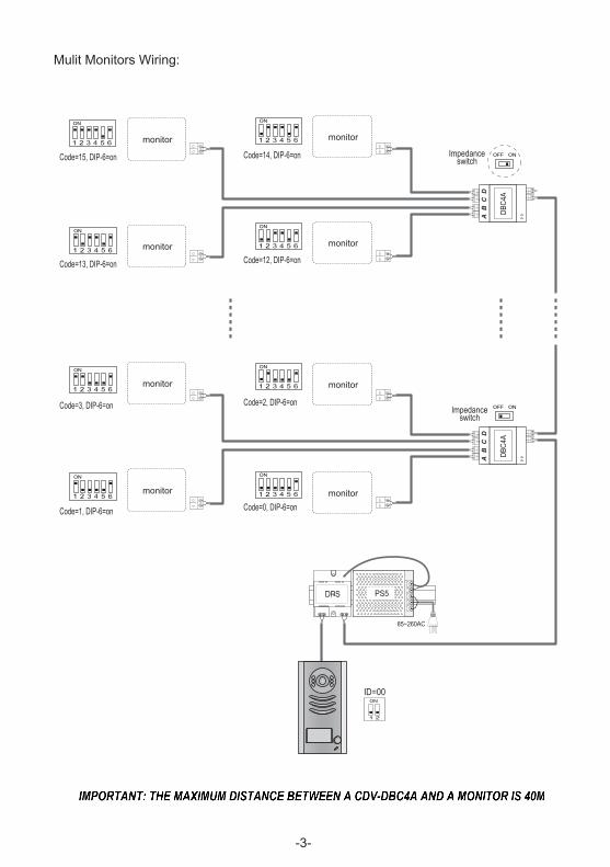
Mulit Monitors Wiring:
OFF ON
OFF ON
monitor
monitor
monitor
monitormonitor
monitor
monitor
monitor
85~260AC
DPS PS5
1 2 3 4 5 6
ON
1 2 3 4 5 6
ON
1 2 3 4 5 6
ON
1 2 3 4 5 6
ON
Code=15, DIP-6=on
Code=13, DIP-6=on
Code=3, DIP-6=on
Code=1, DIP-6=on
1 2 3 4 5 6
ON
1 2 3 4 5 6
ON
1 2 3 4 5 6
ON
1 2 3 4 5 6
ON
Code=14, DIP-6=on
Code=12, DIP-6=on
Code=2, DIP-6=on
Code=0, DIP-6=on
ID=00
1 2
ON
DBC4
A
A B
C D
DBC4
A
A B
C D
Impedance switch
Impedance switch
-3-
Ian
Typewritten text
IMPORTANT: THE MAXIMUM DISTANCE BETWEEN A CDV-DBC4A AND A MONITOR IS 40M

5. Specification
Power Supply : DC20~30V
Working Temperature: -100C~+400C;
Wiring: 2 wires (non-polarity);
Dimension: 89(H)×71(W)×45(D)mm
The design and specifications can be changed without notice to the user. Right to interpret and copyright of this manual are preserved.
DT-ENG-DBC4A-V1 20140702