
CDRL Document Template
165
Core System Concept of Operations (ConOps) Prepared for: US Department of Transportation Research and Innovative Technology Administration ITS Joint Program Office 1200 New Jersey Ave., S.E. Washington D.C. 20590 Attention: [email protected] US Department of Transportation FHWA Office of Acquisition Management 1200 New Jersey Ave., S.E. Washington D.C. 20590 Attention: [email protected] Under: Contract No.: GS-23F-0150S Order No.: DTFH61-10-F-00045 Task: No. 2 _ Date: 19 April 2011 _ __ Enclosure No.: N/A___ __ In Reply Refer To: 11-USDOTSE-LMDM-00018 Lockheed Martin Corporation, Manassas, Virginia 20110-4157
-
Upload
nguyenkhue -
Category
Documents
-
view
231 -
download
0
Transcript of CDRL Document Template

Core System
Concept of Operations (ConOps)
Prepared for:
US Department of Transportation
Research and Innovative Technology Administration
ITS Joint Program Office
1200 New Jersey Ave., S.E.
Washington D.C. 20590
Attention: [email protected]
US Department of Transportation
FHWA
Office of Acquisition Management
1200 New Jersey Ave., S.E.
Washington D.C. 20590
Attention: [email protected]
Under:
Contract No.: GS-23F-0150S
Order No.: DTFH61-10-F-00045
Task: No. 2 _
Date: 19 April 2011 _ __
Enclosure No.: N/A___ __
In Reply Refer To: 11-USDOTSE-LMDM-00018
Lockheed Martin Corporation, Manassas, Virginia 20110-4157

Core System
Concept of Operations
Rev C
ii
CHANGE LOG
Revision Change Summary Author Date
- Initial Release Lockheed Martin 10/28/2010
A Disposition of Customer comments and
Walkthrough comments incorporated in this
revision.
Lockheed Martin 01/19/2011
B Disposition of Customer comments and February
Walkthrough comments incorporated in this
revision.
Lockheed Martin 04/15/2011
C Corrected minor errors and fixed corrupted table
10.8.
Lockheed Martin 04/19/2011
Core System
Concept of Operations
Rev C
iii
TABLE OF CONTENTS
Section Title Page
1.0 Scope ............................................................................................................................................................. 1 1.1 Identification .............................................................................................................................................. 1 1.2 Document Overview .................................................................................................................................. 1 1.3 System Overview ....................................................................................................................................... 3 1.4 Stakeholders ............................................................................................................................................... 6
2.0 Documents ..................................................................................................................................................... 7 2.1 Referenced Documents .............................................................................................................................. 7 2.2 Resource Documents .................................................................................................................................. 7
3.0 Current System ............................................................................................................................................ 10 3.1 Background, Objectives, and Scope ......................................................................................................... 10 3.2 Operational Policies and Constraints ....................................................................................................... 11 3.3 Description of the Current System ........................................................................................................... 11 3.3.1 Current System Overview.................................................................................................................. 11 3.3.2 Current System Architecture ............................................................................................................. 12 3.3.3 POC and Test-bed .............................................................................................................................. 15
3.4 Modes of operation for the Current System ............................................................................................. 15 4.0 Justification for and Nature of Changes ...................................................................................................... 16 4.1 Justification for Changes .......................................................................................................................... 16 4.1.1 Core System Operational Goals......................................................................................................... 21 4.1.2 Core System Needs Overview ........................................................................................................... 22
4.2 Description of Desired Changes ............................................................................................................... 27 4.3 Priorities among Changes ........................................................................................................................ 30 4.4 Changes Considered but not Included ...................................................................................................... 34 4.5 Constraints and Assumptions ................................................................................................................... 35
5.0 Concepts for the Proposed System .............................................................................................................. 38 5.1 Background, Objectives and Scope .......................................................................................................... 39 5.2 Operational Policies and Constraints ....................................................................................................... 40 5.3 Description of the Proposed System ........................................................................................................ 42 5.3.1 The Operational Environment ........................................................................................................... 43 5.3.2 Major Subsystems .............................................................................................................................. 46
5.4 Modes of Operation .................................................................................................................................. 54 5.5 User Types and other involved Personnel ................................................................................................ 57 5.6 Support Environment ............................................................................................................................... 58
6.0 Operational Scenarios .................................................................................................................................. 60 6.1 User Data Exchange (User-User, User-Core-User) ................................................................................. 61 6.2 Certificate Update (User-Core) ................................................................................................................ 63 6.3 Certificate Revocation List Distribution (User-Core) .............................................................................. 66 6.4 Addressing Query (User-Core) ................................................................................................................ 67 6.5 Suspicious Behavior Notification (User-Core) ........................................................................................ 70 6.6 Data Subscription (User-Core) ................................................................................................................. 72 6.7 Data Registration (User-Core) ................................................................................................................. 75 6.8 Remote Services (User-Core-Core) ......................................................................................................... 78 6.9 Core System Maintenance: User Security ................................................................................................ 79 6.10 Core System Operations ........................................................................................................................... 83 6.11 System Expansion .................................................................................................................................... 85 6.12 Core Discovery......................................................................................................................................... 86
7.0 Summary of Impacts ................................................................................................................................... 89 7.1 Operational Impacts ................................................................................................................................. 89
Core System
Concept of Operations
Rev C
iv
7.2 Organizational Impacts ............................................................................................................................ 91 7.3 Impacts during Development ................................................................................................................... 92 7.4 Measuring the Impacts ............................................................................................................................. 93
8.0 Analysis of the Proposed System ................................................................................................................ 94 8.1 Summary of Improvements ...................................................................................................................... 94 8.2 Disadvantages and Limitations ................................................................................................................ 95 8.3 Alternatives and Trade-offs Considered .................................................................................................. 96
9.0 Notes ............................................................................................................................................................ 99 10.0 Appendices ................................................................................................................................................ 102 10.1 Workshops ............................................................................................................................................. 102 10.2 Vancouver, BC Workshop (10 & 11 August, 2010) .............................................................................. 102 10.3 Detroit, MI Workshop (25 & 26 August, 2010) ..................................................................................... 104 10.4 San Jose, CA Workshop (1 & 2 September, 2010) ................................................................................ 107 10.5 Washington DC Workshop (29 & 30 September, 2010)........................................................................ 110 10.6 San Antonio, TX Workshop (5 October, 2010) ..................................................................................... 113 10.7 One-on-Ones Meetings .......................................................................................................................... 114 10.7.1 AERIS .............................................................................................................................................. 114 10.7.2 Commercial Vehicles Operation (CVO) ......................................................................................... 114 10.7.3 Real-Time Data Capture and Management ..................................................................................... 115 10.7.4 Dynamic Mobility Applications ...................................................................................................... 115 10.7.5 Policy ............................................................................................................................................... 116 10.7.6 FHWA Road Weather Management ................................................................................................ 116 10.7.7 Standards ......................................................................................................................................... 117 10.7.8 Transit .............................................................................................................................................. 118 10.7.9 Cooperative Safety .......................................................................................................................... 118
10.8 Consolidated User Input ......................................................................................................................... 119 11.0 Glossary ..................................................................................................................................................... 156

Core System
Concept of Operations
Rev C
v
LIST OF FIGURES
Figure Title Page
Figure 1-1. Core System ConOps Development Process ........................................................................................... 2 Figure 1-2. Core System Boundary Diagram ............................................................................................................. 5 Figure 3-1. VII NSR Context Diagram .................................................................................................................... 11 Figure 3-2. VII NSR Architecture Diagram ............................................................................................................. 14 Figure 4-1. DSRC vs. Cellular OSI Model Layers Comparison .............................................................................. 17 Figure 4-2. System Layers and Users ....................................................................................................................... 18 Figure 4-3. Core System Context Diagram .............................................................................................................. 19 Figure 4-4. Needs Generation Process ..................................................................................................................... 22 Figure 5-1. Core System Subsystem Context ........................................................................................................... 43 Figure 5-2. Single Core Deployment ........................................................................................................................ 45 Figure 5-3. Multiple Overlapping Core Deployments .............................................................................................. 45 Figure 5-4. Multiple Overlapping Core Deployments with Shared Service............................................................. 46 Figure 5-5. Mobile User Subsystem Interfaces ........................................................................................................ 51 Figure 5-6. Center and Field User Subsystem Interfaces ......................................................................................... 51 Figure 5-7. Operator Subsystem Interfaces .............................................................................................................. 52 Figure 5-8. Other Core Subsystem Interfaces .......................................................................................................... 53 Figure 5-9. Core State Transition Diagram .............................................................................................................. 56 Figure 5-10. Subsystem Operational Modes Diagram ............................................................................................. 57 Figure 6-1. Example Activity Diagram .................................................................................................................... 61 Figure 6-2. User Data Exchange Context Diagram .................................................................................................. 62 Figure 6-3. User Data Exchange Activity Diagram ................................................................................................. 63 Figure 6-4 Certificate Update Context Diagram ...................................................................................................... 64 Figure 6-5. Certificate Update Activity Diagram ..................................................................................................... 65 Figure 6-6. Certificate Revocation List Distribution Context Diagram ................................................................... 66 Figure 6-7. Certificate Revocation List Distribution Activity Diagram ................................................................... 67 Figure 6-8. Addressing Query Context Diagram ...................................................................................................... 68 Figure 6-9. Addressing Query Activity Diagram ..................................................................................................... 69 Figure 6-10. Suspicious Behavior Notification Context Diagram ............................................................................ 70 Figure 6-11. Suspicious Behavior Notification Activity Diagram ........................................................................... 71 Figure 6-12. Data Subscription Context Diagram .................................................................................................... 72 Figure 6-13. Data Subscription Activity Diagram (1 of 2) ....................................................................................... 73 Figure 6-14. Data Subscription Activity Diagram: Credentialing (2 of 2) ............................................................... 74 Figure 6-15. Data Registration Context Diagram ..................................................................................................... 75 Figure 6-16. Data Registration Activity Diagram .................................................................................................... 77 Figure 6-17. Core System Operation Context Diagram ........................................................................................... 78 Figure 6-18. Core System Operations Activity Diagram ......................................................................................... 79 Figure 6-19. Core System Maintenance Context Diagram ....................................................................................... 80 Figure 6-20. Core System Maintenance Activity Diagram (1 of 2) ......................................................................... 81 Figure 6-21. Core System Maintenance Activity Diagram (2 of 2) ......................................................................... 82 Figure 6-22. Core System Operations Context Diagram .......................................................................................... 83 Figure 6-23. Core System Operations Activity Diagram ......................................................................................... 84 Figure 6-24. System Expansion Context Diagram ................................................................................................... 85 Figure 6-25. System Expansion Activity Diagram ................................................................................................... 86 Figure 6-26. Core Discovery Context Diagram ........................................................................................................ 87 Figure 6-27. Core Discovery Activity Diagram ....................................................................................................... 88

Core System
Concept of Operations
Rev C
vi
LIST OF TABLES
Table Title Page
Table 4-1. Core System and VII Needs Comparison ............................................................................................... 28 Table 4-2. Essential Features .................................................................................................................................... 31 Table 4-3. Desirable Features ................................................................................................................................... 33 Table 5-1. Subsystem to Needs Traceability Matrix ................................................................................................ 49 Table 9-1. Abbreviation and Acronym List.............................................................................................................. 99 Table 10-1. Consolidated User Input ...................................................................................................................... 119 Table 11-1. Glossary .............................................................................................................................................. 156

Core System
Concept of Operations
Rev C
1
1.0 SCOPE
1.1 Identification
This document describes the Concept of Operations (ConOps) of the Core System for the United States
Department of Transportation‘s (USDOT) next generation integrated transportation system.
The previous Vehicle Infrastructure Integration (VII) program provided much of the research that led to
this next generation system. The economic and technology climates have changed significantly since the
VII program however; as a result much of what may have been considered viable during that program is
no longer practical. For further information about VII‘s vision, please reference the VII Concept of Op-
erations.
1.2 Document Overview
The USDOT initiated this Systems Engineering (SE) project to define the ConOps, requirements, and
architecture for a system that will enable safety, mobility, and environmental applications in an envi-
ronment where vehicles and personal mobile devices are connected wirelessly, hereafter referred to as
the connected vehicle environment. This ConOps is a user-oriented document describing characteristics
of a to-be-delivered system from the user‘s viewpoint. It includes a detailed description of how an op-
erational concept is applied, with corresponding interactions and information flows between system
elements and actors. It identifies the functions carried out by the system, users that interact with the sys-
tem, their roles and responsibilities.
Figure 1-1 shows the process used for developing the Core System ConOps. This process began with the
identification, analysis and documentation of user needs based on input collected and solicited from a
wide variety of sources. Inputs to the ConOps activities include:
Public stakeholder workshops
One-on-one meetings with USDOT stakeholder representatives
Project goals and objectives identified in the SE contract
Interviews with VII program participants including members of the Crash Avoidance Metrics Part-
nership (CAMP), Vehicle Infrastructure Integration Consortium (VIIC) and the Booz Allen Hamil-
ton (BAH) team
Documents from the VII program, research, and international activities (see Section 2.0)
Research conducted under the VII program provides the basis for much of what has become the Core
System. VII concepts such as probe data generation and collection, publish-subscribe and the 5.9 GHz
Dedicated Short-Range Communication (DSRC) communications architecture provide much of the
foundation for the Core System.
Figure 1-1 is an example of a type of figure used extensively in the ConOps to document processes. This
style of figure comes from the International Council on Systems Engineering (INCOSE) Systems Engi-
neering Handbook V3.1. It defines the actions of the actor in question (in this case the ConOps develop-
ers) in the center box. The inputs box represents the interactions and inputs of stakeholder workshops,
one-on-one meetings, meetings with CAMP, VIIC and BAH. Enablers are those items that help achieve
or influence an outcome. The outputs of the ConOps development process are captured in this ConOps
document, most importantly by the needs defined in Section 4.0. These needs provide the foundation for
traceability to the system requirements to be defined in the System Requirements Specification (SysRS).

Core System
Concept of Operations
Rev C
2
The Core System ConOps further reflects:
Changes in assumptions and constraints identified by the USDOT and other key stakeholders
Lessons learned and source material from the Cooperative Intelligent Transport System efforts
from both Europe and Asia
Customer (user) needs from which requirements can be developed
The structure of this ConOps document is based on Institute of Electrical and Electronics Engineers
(IEEE) Standard 1362-1998 IEEE Guide for Information Technology, System Definition, Concept of
Operations (ConOps) Document. The ConOps document consists of the following sections:
Section 1.0 provides an overview of the Core System and an introduction to this ConOps docu-
ment.
Section 2.0 lists the documents used as background information or as a source of user needs. Many
of these documents are artifacts from the VII program.
Section 3.0 provides an overview of the current system. This is used as the basis for analyzing the
needs and capabilities to be considered in the revised system.
Section 4.0 discusses the Core System needs and the process followed to identify and define them.
Section 5.0 describes the proposed Core System including its scope, operational environment, op-
erational policies and constraints, major system services, interfaces to external systems and subsys-
tems.
ControlsContract Assumptions
Project Management Plan
Configuration Management Plan
Systems Engineering Management Plan
InputsStakeholder Workshops
Project Goals and Objectives
One-on-One Meetings
Reference Documents
CAMP, VIIC and BAH discussions
EnablersStakeholder Involvement
Action Items
Risk Items
ActivitiesTransform User Inputs into User Needs
Define Operational Vision from User Inputs
Develop Concept of Operations
Develop Operational Scenarios
OutputsCompletion of the Concept of Operations
Basis for Requirements Traceability
Figure 1-1. Core System ConOps Development Process

Core System
Concept of Operations
Rev C
3
Section 6.0 provides a set of scenarios developed to illustrate the Core System‘s support for the
needs defined in Section 4.0. Each scenario includes a brief textual description of what the scenario
discusses. Then a context diagram is presented, describing the inputs, enablers and controls that
feed into the Core system, and what outputs are produced. Last, one or more activity diagrams de-
scribe the interactions between users and core subsystems.
Section 7.0 provides a summary of the operational, organizational and developmental impacts of
the proposed Core System.
Section 8.0 discusses the improvements provided by the proposed system, its disadvantages and
limitations, and any alternatives or trade-offs considered.
Section 9.0 contains an alphabetical listing of acronyms used in this document.
Section 10.0 consists of several appendices including a list of participants in each of the five stake-
holder workshops, attendees at each of the one-on-one meetings, and the stakeholder input table.
Section 11.0 contains a Glossary of terms in this document.
Within these sections, the Core System is discussed in terms of the environment within which it will op-
erate, the services it provides, and the high-level design it supports. This foundation will allow for the
definition of requirements and system architecture that support the vision set forth in this ConOps. It
provides the system boundaries and documents an understanding of the needs of the stakeholders who
will participate in and benefit from its operation.
The intended audience for this ConOps includes: USDOT, transportation managers (including state and
local DOTs), vehicle manufacturers, information service providers, fleet managers, commercial vehicle
operators and regulators, application developers, and potential Core System acquirers, deployers, opera-
tors, and maintainers.
1.3 System Overview
The USDOT‘s connected vehicle program envisions the combination of applications, services and sys-
tems necessary to provide safety, mobility and environmental benefits through the exchange of data be-
tween mobile and fixed transportation users. It consists of the following:
Applications that provide functionality to realize safety, mobility and environmental benefits,
Communications that facilitate data exchange, and
Core Systems, which provide the functionality needed to enable data exchange between and
among mobile and fixed transportation users.
The Core System‘s main mission is to enable safety, mobility and environmental communications-based
applications for both mobile and non-mobile users. The scope of the Core System includes those enabl-
ing technologies and services that will in turn provide the foundation for applications. The system boun-
dary for the Core System is not defined in terms of devices or agencies or vendors but by the open, stan-
dardized interface specifications that govern the behavior of all interactions between users.
The Core System supports a distributed, diverse set of applications. These applications use both wireless
and wireline communications to provide:
Wireless communications with and between mobile elements including vehicles (of all types), pe-
destrians, cyclists, and other transportation users
Wireless communications between mobile elements and field infrastructure

Core System
Concept of Operations
Rev C
4
Wireless and wireline communications between mobile elements, field infrastructure, and back of-
fice/centers1
At the time of the VII program‘s onset, the Federal Communications Commission (FCC) allocated 75
Megahertz (MHz) of spectrum in the 5.9 Gigahertz (GHz) frequency range for the primary purpose of
improving transportation safety. In addition to safety of life and public safety applications, the FCC‘s
Final Report and Order also allowed private and non-safety applications to make use of the spectrum on
a lower priority basis. This allowed the VII program and associated research efforts to test the capabili-
ties of 5.9 GHz DSRC for vehicular based safety and mobility applications.
Since then, the requirement to use 5.9 GHz communications technologies was refocused on safety appli-
cations. The SE Project includes consideration of other means of communication, while still maintaining
5.9 GHz DSRC for Vehicle to Vehicle (V2V) and Vehicle to Infrastructure (V2I) safety applications be-
cause of its high availability and very low latency characteristics.
Additionally, VII only considered integrating new vehicles, sourcing all vehicles‘ On-board Equipment
(OBE) from Original Equipment Manufacturers (OEMs). Now, retrofit of existing vehicles and 3rd
party
aftermarket solutions for OBE are allowed.
VII considered that some safety and mobility applications would be installed on all participating ve-
hicles. Some safety applications will still likely be mandated to be installed on participating vehicles.
Non-safety applications will be installed on an opt-in basis however.
A critical factor driving the conceptual view of the Core System and the entire connected vehicle envi-
ronment is the level of trustworthiness between communicating parties. A complicating factor is the
need to maintain the privacy of participants, chiefly but not necessarily exclusively through anonymous
communication. The Core System is planning anonymity into the trusted exchange of data, using the
existing Privacy Principles2 as guidelines, and balancing privacy against security and safety.
While the Core System is being planned for anonymity, it is also providing a foundation from which to
leverage alternative communications methods for non-safety applications. These alternatives are typical-
ly available on the market today; however, the levels of anonymity and privacy inherent to these systems
are typically governed by agreements between communication providers and consumers. So, while pri-
vacy is not compromised for an individual, what happens between that individual and their communica-
tion provider (e.g., 3G service provider) very well may compromise privacy. Similarly, some application
providers may require personal information in order to function, requiring the user to opt-in to use that
application.
VII was conceived as a nationally deployed and managed system. This is no longer considered practical.
The next generation integrated transportation system will be deployed locally and regionally. It must be
able to grow organically to support the changing needs of its user base. Deployments will likely be ma-
naged regionally but follow federally mandated standards to ensure that the essential capabilities are
compatible no matter where the deployments are established.
The Core System concept documented here distinguishes communications mechanisms from data ex-
change and from the services needed to facilitate the data exchange. The functions and their relationship
to each other are further defined in Section 4.0. In short, the Core System is responsible for providing
1 The terms ―back office‖ and ―center‖ are used interchangeably throughout this document. Center is a traditionally transpor-
tation-focused term, evoking management centers to support transportation needs, while back office generally refers to com-
mercial applications. From the perspective of the Core System these are considered the same. 2 VII Privacy Policies Framework version 1.0.2

Core System
Concept of Operations
Rev C
5
the services needed to facilitate the data exchange. The contents of the data exchange are determined by
applications, unless the data exchange is used as part of the facilitation process between the user and the
Core.
The Core System provides the functionality required to support safety, mobility and environmental ap-
plications. This same functionality may enable commercial applications, but that is not a driving factor,
rather a side effect. The primary function of the Core System is facilitation of communications between
users, some of which must also be secure. The Core may also provide data distribution and network
support services, depending on the needs of the Core deployment. Section 5.0 describes the Core System
in more depth and with more detail.
The Core System exists in an environment where it facilitates interactions between vehicles, field infra-
structure and backoffice users, as illustrated in Figure 1-2. Students of VII should note that the following
are not part of the Core System:
Mobile Users (e.g., vehicle devices, pedestrian smartphones) – any user device.
Roadside Equipment (RSE) – both public and commercial fixed devices.
Transportation Management Centers (TMC) and other public or private backoffice or centers
Vehicles
Transit
Commercial
Vehicles
Emergency
Vehicles
Map, weather,
road data, etc.
After-Market
Devices
Wi-Fi, 3G, 4G and other forms of wireless
and optional wired communication
Communications
Core
System
Pedestrians
Roadside
Equipment (RSE)
Traffic Signal
with Roadside
Equipment
(RSE)
Transportation
Management
Center (TMC)
Figure 1-2. Core System Boundary Diagram
While the above users, their devices and software applications are outside of the Core System; the Core
System is still responsible for facilitating their security; this is chiefly done by providing digital certifi-
cate-based mechanisms to ensure trust between users. The Core also provides networking services to
facilitate communications, though it does not comprise the communications network.

Core System
Concept of Operations
Rev C
6
It is also important to note that the Core System is not meant to mandate or change existing transporta-
tion equipment, technology or transportation centers. The Core System provides mechanisms for effi-
ciently collecting and distributing transportation data, but does not necessarily replace existing systems,
though it is likely that many existing data collection mechanisms will be made obsolete by its data col-
lection and distribution function.
1.4 Stakeholders
Core System stakeholders span the breadth of the transportation environment, including users, operators,
deployers and maintainers of roads, devices and vehicles. Core System stakeholders include:
Transportation Users, e.g., private vehicle drivers, public safety vehicle operators, commercial
vehicle operators, passengers, cyclists and pedestrians
Transportation Operators, e.g. traffic managers, transit managers, fleet managers, toll operators,
road maintenance and construction
Public Safety, e.g. incident and emergency management, including fire, police and medical sup-
port
Information Service Providers, e.g. data and information providers for transportation-related da-
ta, including traffic, weather and convenience applications
Environmental Managers, including emissions and air quality monitors
Original Equipment vehicle Manufacturers (OEMs)
In-vehicle device manufacturers
Communications Providers, including cellular network operators
Federal regulatory and research agencies under the umbrella of USDOT

Core System
Concept of Operations
Rev C
7
2.0 DOCUMENTS
This section is divided into two portions. The first section lists the documents that are explicitly refe-
renced as part of this document. The second section lists the documents or other resources that were
used for background information and as a source for potential user needs during the development of this
ConOps though there may not be a direct reference.
2.1 Referenced Documents
IEEE Std. 1362 – IEEE Guide for Information Technology, System Definition, Concept of Opera-
tions (ConOps) Document, 22 Dec 1998
IEEE 1609.4 Standard for Wireless Access in Vehicular Environments (WAVE) - Multi-Channel
Operations, Oct 2006
INCOSE Systems Engineering Handbook version 3.1, August 2007.
Vehicle Infrastructure Integration (VII) USDOT Day-1 Use Case Descriptions, v1.0, May 2006
Vehicle Infrastructure Integration Consortium (VIIC) Standards Recommendations, VIIC Docu-
ment SYS090-05, May 23, 2010
VII Concept of Operations (ConOps), BAH, v1.2, September-06
VII National System Requirements (NSR), BAH, v1.3.1, April-08
VII Privacy Policies Framework, Version 1.0.2, February 16, 2007
2.2 Resource Documents
A Provisional Technical Architecture for the VII, PB Farradyne, July 2004
A Summary of European Cooperative Vehicle Systems Research Projects, Jun-09
Achieving the Vision: Policy White Paper, 4/30/2010
An Initial Assessment of the Ability of 4G Cellular Technology to Support Active Safety Applica-
tions, Final Draft, 11/18/2009
Architecture Specification for the Vehicle and Certificate Authority Certificate Management Sub-
systems, VIIC
CAMP Security Final Report, Draft, 8/31/2010
CEN TC278-WG16_ISO TC204-WG18_2nd Meeting-Sept-2010_ Agenda, 7/24/2010
Certificate Authority (CA) Subsystem Specification, BAH, v1.1, February-07
Certificate Management Concept of Operation, VIIC, SEC 110-01
Cooperative Intersection Collision Avoidance System for Violations (CICAS-V) for Avoidance of
Violation-Based Intersection Crashes Paper, Michael Maile and Luca Delgrossi, March 2009
Data Element Dictionary, BAH, v1.0, February-07
EC Standardization Mandate M/453 Preliminary work plan for ETSI TC ITS, 7/27/2010
Enterprise Network Operations Center (ENOC) Subsystem Specification, BAH, v1.1
ETSI Intelligent Transport Systems (ITS) Security Services and Architecture, ETSI TS 102 731,
v1.1.1, 9/21/2010
European ITS Framework Architecture, v4.0, 2009
European ITS Communication Architecture, v3.0, 2010
Final Report: VII POC Executive Summary – Infrastructure (Volume 1B), BAH
Final Report: VII POC Executive Summary – Vehicles (Volume 1A), VIIC
Core System
Concept of Operations
Rev C
8
Final Report: VII POC Results and Findings – Infrastructure (Volume 3B), BAH
Final Report: VII POC Results and Findings – Vehicles (Volume 3A), VIIC
Final Report: VII POC Technical Description – Infrastructure (Volume 2B), BAH, 5-15-09 Final
Final Report: VII POC Technical Description – Vehicles (Volume 2A), VIIC, volume 2
Functional and Performance Requirements for the VII POC OBE Subsystem, VIIC
IEEE P1609 Working Group Meeting Notice and Draft Agenda, 7/14/2010
IEEE 1609.1 Standard for Wireless Access in Vehicular Environments (WAVE) - Resource Man-
ager, Oct 2006
IEEE 1609.2 Standard for Wireless Access in Vehicular Environments (WAVE) - Security Servic-
es for Applications and Management Messages, Jun 2006
IEEE 1609.3 Standard for Wireless Access in Vehicular Environments (WAVE) - Networking
Services, Apr 2007
IEEE 802.11p-2010, 15 July 2010
IEEE Standard 802.16: A Technical Overview, C80216-02_05, 6/4/2002
IEEE Standard for Software Configuration Management Plans, 12 Aug 2010
IEEE Std. 1028-1997 – IEEE Standard for Software Reviews, 9 December 1997
IEEE Std. 1220-2005 – IEEE Standard for Application and Management of Systems Engineering
Process, 9 September 2005
Information technology—Open Systems Interconnection—Basic Reference Model: The Basic
Model, ISO/IEC 7498-1:1994
Infrastructure Lexicon, BAH, v1.1, February-07
Intelligent Transport Systems (ITS) Communications Architecture, ETSI EN 302 665 V1.1.1
(2010-09), European Telecommunications Standards Institute 2010.
ITS Standards Development Organizations Membership Overlap Analysis, Jan-10
ITS Strategic Research Plan, 2010-2014: Executive Summary, US DOT, 3/29/2010
Joint CEN and ETSI Response to Mandate M/453 – EC Comments, 7/27/2010
M/453 Co-operative Systems Progress Report, 7/27/2010
Mileage-based User Fee Technology Study, 8/7/2009
Network Subsystem Specification Addendum, BAH, v1.0.1a, March-07
Network Subsystem Specification, BAH, v1.1, April-07
OBE Communications Manager Subsystem Requirements Specification, VIIC, ENA 110-02
OBE Subsystem Design Description, VIIC, SYS 112-02 (OBE), SYS 112-01
OBE to RSE Interface Requirements Specification, VIIC, SYS 120-04
POC OBE Subsystem Functional and Performance Requirements, VIIC, SYS 110-02
POC Probe Data Collection Vehicle Application Requirements, VIIC, APP 220-01
POC Trippath Generation Application Requirements, VIIC, APP 220-04
Policy Roadmap for Vehicle-to-Vehicle (V2V) and Vehicle-to-Infrastructure (V2I) Safety, Draft:
05/19/2010
Potential Haul-In Aftermarket Device Suppliers, 6/11/2010
Risk Management Plan for the Deployment of IVI Collision Avoidance Safety Systems, Draft
Ver 1, 11/4/2004
RSE Procurement Analysis, BAH, v1.0, June-06,

Core System
Concept of Operations
Rev C
9
Roadway Geometry and Inventory Trade Study for Applications, 7/1/2010
RSE Software Requirements Specification (SRS), BAH, v2.0, July-07
RSE Subsystem Specification, BAH, v1.2
SAE J2735 - Dedicated Short Range Communications (DSRC) Message Set Dictionary, v2, Nov
2009
SAE J2735 Standard: Applying the Systems Engineering Process, 6/30/2010
Service Delivery Node (SDN) Subsystem Specification, version 1.1, February 2007
Standardization Mandate
Transit Crosscutting Application Development and Implementation Program Plan and Roadmap
(2010-2014), 3.1, Jul-10
US Code Section 36 CFR Part 1194 - Electronic and Information Technology Accessibility Stan-
dards (36 CFR 1194 implements Section 508 of the Rehabilitation Act of 1973, as amended), Dec.
21, 2000
Vehicle Safety Communications – Applications (VSC-A) Project: Crash Scenarios and Safety Ap-
plications, Michael Maile, May 2, 2007
Vehicle Safety Communications in the United States Paper, Michael Shulman and Richard Deer-
ing, March 2007
Vehicle Segment Certificate Management Concept of Operations, VIIC, SEC 110_01
Vehicle Segment Security Plan (Security ConOps), SEC 100-10, Jan 2007
Vehicle-Vehicle and Vehicle-Infrastructure Communications based Safety Applications, Michael
Maile, February 2010
VII Architecture and Functional Requirements, PB Farradyne, VII Architecture version 1.1
2005_07_20
VII Communications Analysis Report, BAH, v3.0, July-06
VII System Discussion, 7/8/2010
VII USDOT Day-1 Use Case Descriptions, BAH, Combined Final v1.0, May-06
X-072 Interface Requirements Specification, SYS 120-02

Core System
Concept of Operations
Rev C
10
3.0 CURRENT SYSTEM
3.1 Background, Objectives, and Scope
This section provides an overview of the current system. Identifying the current transportation system is
not straightforward: while the VII program was never deployed, it did include a national system specifi-
cation, prototype design and test-bed for a next-generation system enabling V2V and V2I wireless
communications. Because of this applicable research-focused heritage, the current system baseline is
defined in the VII National System Requirements (NSR) document.
The VII program‘s objectives were to seek significant improvement in safety, mobility, and commerce
by deploying a communications infrastructure on roadways nationwide and installing DSRC radios in all
production light vehicles. VII presented opportunities to take the next great step forward toward improv-
ing surface transportation. VII would provide safety features on vehicles that could prevent accidents at
intersections, improve traffic management, enhance traffic mobility, optimize emergency response and
keep vehicles from running off the road.
Under the VII program stakeholders worked together to explore the possible applications that would be
enabled when vehicles could communicate directly with the infrastructure. VII stakeholders included
vehicle manufacturers, Federal and State highway agencies, and engineering and communications sup-
port companies. USDOT‘s role included funding and fostering VII research, initiatives, applications and
other related technologies. Other public transportation agencies provided experience, reference and the
infrastructure foundation for the Proof-of-Concept (POC). Private companies, including vehicle OEMs,
communications and other firms developed the NSR, other documents and constructed and operated the
POC and ensuing test-bed.
For VII, all communications between vehicles and with vehicles were to use 5.9 GHz DSRC. In addi-
tion, the OEMs would install a DSRC radio only on new production vehicles; no consideration was giv-
en for aftermarket and retrofit devices3.
DSRC uses 5.9 GHz in the US which is allocated into seven 10 MHz channels, four of which can be
combined into two 20 MHz channels. This allows RSEs in local proximity of each other (approximately
1,000 meters) to provide services without causing interference. It also allows for use of some existing
commercial IEEE 802.11 based radio components – the same standard interfaces that govern wireless
networking access devices (e.g., Wi-Fi). Since it is critical for safety reasons to ensure that all OBE and
RSE can hear each other, and the standards developers did not want to assume the use of multiple radio
transceiver systems (or very wide band receiver systems), a method for channel management was devel-
oped and is described in IEEE 1609.4.
The concepts that were defined and tested during VII along with the standards that have evolved through
VII and other related efforts around the world can be considered as stepping stones from stand-alone,
proprietary technologies to a more integrated and open standards-based environment. The Core System
engineering effort builds upon the results of the VII initiative. Its enabling capabilities may not necessar-
ily replace any existing systems because of deployment strategies and budget constraints, but it will fit
alongside and enhance existing Intelligent Transportation Systems (ITS).
3 The published version of the NSR does include concepts for non-original equipment, but little other published documenta-
tion acknowledges this. The concept of aftermarket integration was envisioned, but not studied or focused upon in POC test-
ing or concurrent research.
Core System
Concept of Operations
Rev C
11
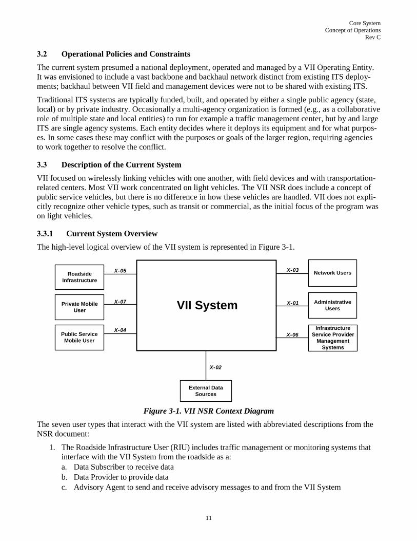
3.2 Operational Policies and Constraints
The current system presumed a national deployment, operated and managed by a VII Operating Entity.
It was envisioned to include a vast backbone and backhaul network distinct from existing ITS deploy-
ments; backhaul between VII field and management devices were not to be shared with existing ITS.
Traditional ITS systems are typically funded, built, and operated by either a single public agency (state,
local) or by private industry. Occasionally a multi-agency organization is formed (e.g., as a collaborative
role of multiple state and local entities) to run for example a traffic management center, but by and large
ITS are single agency systems. Each entity decides where it deploys its equipment and for what purpos-
es. In some cases these may conflict with the purposes or goals of the larger region, requiring agencies
to work together to resolve the conflict.
3.3 Description of the Current System
VII focused on wirelessly linking vehicles with one another, with field devices and with transportation-
related centers. Most VII work concentrated on light vehicles. The VII NSR does include a concept of
public service vehicles, but there is no difference in how these vehicles are handled. VII does not expli-
citly recognize other vehicle types, such as transit or commercial, as the initial focus of the program was
on light vehicles.
3.3.1 Current System Overview
The high-level logical overview of the VII system is represented in Figure 3-1.
VII System
X-02
X-05 X-03
X-04
X-07
Private Mobile
User
Roadside
Infrastructure
External Data
Sources
Network Users
Administrative
Users
Public Service
Mobile User
X-01
X-06
Infrastructure
Service Provider
Management
Systems
Figure 3-1. VII NSR Context Diagram
The seven user types that interact with the VII system are listed with abbreviated descriptions from the
NSR document:
1. The Roadside Infrastructure User (RIU) includes traffic management or monitoring systems that
interface with the VII System from the roadside as a:
a. Data Subscriber to receive data
b. Data Provider to provide data
c. Advisory Agent to send and receive advisory messages to and from the VII System

Core System
Concept of Operations
Rev C
12
d. Transaction Agent to conduct informational transactions with vehicles or centers.
2. Private Mobile User (PMU) is the VII-enabled, personal or public vehicle or non-original equip-
ment (aftermarket, portable, handheld, etc.) operated by the general public, agency, or corporation.
PMU interacts with the VII System as a:
a. Data Provider to provide data
b. Data Advisory Subscriber to receive data
c. Transaction Agent to conduct informational transactions
3. Public Service Mobile User (PSMU) is a VII-enabled uniquely identifiable public mobile user,
such as an ambulance, fire truck, police or road maintenance vehicle, or non-original equipment
(aftermarket, portable, handheld, etc.). PSMU interacts with the VII System as a:
a. Data Provider to provide data
b. Data Advisory Subscriber to receive data
c. Transaction Agent to conduct informational transactions
4. The Network User is the public or private back office entity that uses VII System services. A Net-
work User interacts with the VII System as a:
a. Network Subscriber to receive data
b. Network Advisory Provider to provide data
c. Network Transaction Agent to conduct informational transactions
5. The Administrative User manages VII System services; specifically it manages VII assets, enables
or disables services, monitors VII System operations in selected domains, manages access and au-
thorization of Network Users.
6. The Infrastructure Service Provider Management System is the telecommunications service pro-
vider customer service and network management systems. This may include the communications
infrastructure provided by telecommunications companies.
7. The External Data Sources of the VII System include:
a. Global Positioning System (GPS) to provide positioning and timing information
b. Differential GPS (DGPS) Corrections providing enhanced positioning information to those VII
subsystems that require more accurate positioning information
c. Roadway maps with sufficient accuracy to support vehicle safety applications
3.3.2 Current System Architecture
As part of the overall VII program a set of 100 use cases were developed by various stakeholder groups.
The use cases provided insight into the needs and priorities of the various stakeholders. From the initial
set of 100, 20 use cases were identified and articulated in more detail. These represented applications
expected to be available at the initial deployment of VII and were known as the ―Day-1 Use Cases.‖ It
was from these 20 use cases that the VII services were developed.
The VII architecture provides ten services designed to support safety, mobility and commercial applica-
tions. The VII services are:
Advisory Message Distribution Service (AMDS): provides a mechanism for the Network User and
Roadside Infrastructure User to send messages to PMU/PSMU. For the Network User, this in-
cludes the ability to select from geographic areas and broadcast messages to all PMU/PSMU in the
area. For the Roadside Infrastructure User, the communication is local to the vicinity of the RIU
(generally within 1000m).

Core System
Concept of Operations
Rev C
13
Communications Service: Provides data exchange between PMU/PSMU and other PMU/PSMU,
Roadside Infrastructure User and Network User.
Information Lookup Service: Provides underlying network support capabilities enabling communi-
cations between users of all types.
Management Service: Provides maintenance, monitoring, configuration of non-mobile system
components.
Map Element Distribution Service: Distributes small maps containing roadway geometry and lane
features to PMU/PSMU.
Positioning Service: Distributes positioning and position correction information to the
PMU/PSMU and VII subsystems (Figure 3-2) that require it.
Probe Data Service (PDS): Collects probe data from PMU/PSMU, distributes data to Network Us-
ers and Roadside Infrastructure Users using publish-subscribe methodology.
Roadside Infrastructure Support Service: Provides compatibility and formatting for Roadside In-
frastructure Users (e.g., SPAT, tolling).
Security Service: Security protection against unauthorized use or sabotage of internal systems. Al-
so maintains authorizations, determining what permissions each user has.
System Time Service: Distributes timing information to users and VII subsystems.
These services are implemented by the VII Architecture illustrated in Figure 3-2.
Core System
Concept of Operations
Rev C
14
Private Mobile User
Roadside
Infrastructure User
X-052
Public Service
Mobile User
VII SystemVII Infrastructure
Certificate
Authority
KeyPhysical and Logical
Logical
Between Instances
-A-nnn
Infrastructure Service
Provider Management
System
X-061
Network Users
Network Data Subscriber
Network Advisory Provider
Network Transaction Agent
External Data Sources
GPS Signals
DGPS Corrections
Reference Maps
Administrative User
X-011
RSE
SDN
ENOC
• X-062
▲I -08• I-07
▲I -11
• I-10
• X-012
• X-034
• X-027
I-12
• A- nnn
▲ A- nnn
Public Service
Mobile User
Segment
I-04
• I-16
I-01
A-nnn
▲ALL• ALL
X-054
l X-055
X-053
X-051
X-071 Private
Mobile User
Segment
X-041
X-022
X-021
I-15
I-14
I-0
2
:External Data Source
GPS Signals
X-072
X-073
PSMU Data Provider
PSMU Advisory Agent
PSMU Transaction Agent
X-042
X-043
X-023
GPS SignalsExternal Data Source
Local Data Subscriber
Local Data Provider
Local Advisory Agent
Local Transaction Agentl
l
l
I-03
I-05
I-13
PMU Data Provider
PMU Advisory Agent
PMU Transaction Agent
I-06
I-11
I-09X-026
X-025
X-024
X-033
X-032X-031
l
l
l
l
l
Registered Entity (RE)
Interface to ENOC
Managed Network Element
(MNE) Interface to ENOC
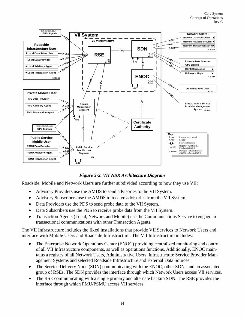
Figure 3-2. VII NSR Architecture Diagram
Roadside, Mobile and Network Users are further subdivided according to how they use VII:
Advisory Providers use the AMDS to send advisories to the VII System.
Advisory Subscribers use the AMDS to receive advisories from the VII System.
Data Providers use the PDS to send probe data to the VII System.
Data Subscribers use the PDS to receive probe data from the VII System.
Transaction Agents (Local, Network and Mobile) use the Communications Service to engage in
transactional communications with other Transaction Agents.
The VII Infrastructure includes the fixed installations that provide VII Services to Network Users and
interface with Mobile Users and Roadside Infrastructure. The VII Infrastructure includes:
The Enterprise Network Operations Center (ENOC) providing centralized monitoring and control
of all VII Infrastructure components, as well as operations functions. Additionally, ENOC main-
tains a registry of all Network Users, Administrative Users, Infrastructure Service Provider Man-
agement Systems and selected Roadside Infrastructure and External Data Sources.
The Service Delivery Node (SDN) communicating with the ENOC, other SDNs and an associated
group of RSEs. The SDN provides the interface through which Network Users access VII services.
The RSE communicating with a single primary and alternate backup SDN. The RSE provides the
interface through which PMU/PSMU access VII services.

Core System
Concept of Operations
Rev C
15
VII enables the following types of communication:
Geo-cast messages from Network Users to PMU/PSMU
Point-to-point messages between Network Users and PMU/PSMU, initiated by PMU/PSMU
Uni-cast messages between PMU/PSMU
Uni-cast messages between Roadside devices and PMU/PSMU
VII Services are implemented primarily at the SDNs, but the ENOC and RSE have roles implementing
some parts of services. For example, the RSE provides proxies to access services, and can cache infor-
mation locally. The ENOC provides aspects of the management and security services.
The Private Mobile User Segment and Public Service Mobile User Segment provide the mechanism
whereby the PMU/PSMU interface with the VII System. The functionality for these subsystems is con-
tained in a mobile system. This includes but is not limited to what is traditionally called OBE, but could
also include aftermarket or handheld implementations. Communication with the RSE uses a DSRC ra-
dio.
The Certificate Authority (CA) issues keys and certificates to facilitate digitally signed and encrypted
messaging. The CA also publishes lists of revoked certificates, so that users can verify that a particular
message came from a valid, trustworthy source.
Section 4.2 of this ConOps includes a comparison of the services implemented by VII with the needs of
the Core System.
3.3.3 POC and Test-bed
While VII was never fully deployed, various test-bed activities were carried out and in some cases are
still active. One of the early implementations of VII was the deployment of the POC system that in-
cluded 55 RSEs placed at various locations in the northwestern Detroit suburbs. These RSEs were linked
to two SDNs, one in Virginia and the other in Michigan, using a variety of different back haul technolo-
gies including 3G cellular, Wi-Fi and wire line communications. The POC deployment has since been
migrated to a test-bed environment to be used to test the next generation transportation-related technolo-
gies.
Because developing and testing all 20 Day-1 VII Use Cases would have been impracticable, the POC
program identified a subset of use cases that exercise the core functions. These were then implemented
and tested in ways to assess both the functionality and the baseline performance of the system. The sys-
tem would provide these core functions in the same way regardless of the specific details of the applica-
tion.
3.4 Modes of operation for the Current System
The VII NSR document limited discussions on modes and states of the system, but it did identify re-
quirements for failed and degraded services (which correlates with degradation modes and states). It also
identified the need for restoration mechanisms to recover the system to an operational state.

Core System
Concept of Operations
Rev C
16
4.0 JUSTIFICATION FOR AND NATURE OF CHANGES
This section discusses Core System operational goals, system needs and user needs. Operational goals
establish parameters and targets for system performance. Needs identify what the system needs to do:
System needs describe what the system needs to do
in order to meet operational goals.
User needs describe what the system needs to do in
order to provide a foundation for applications.
Connected Vehicle applications are not part of the Core System, but consideration of those applications
drives the nature of the system. The Core needs to enable applications that meet the overarching US-
DOT goals of improving safety, mobility and the environment.
The existing VII system does not entirely meet these system and user needs, is not focused on environ-
mental improvements, and thus does not enable applications as envisioned. It provides some of the basis
for facilitating trust between users, but not in a sufficiently scalable way. It does not account for the dif-
ferences between DSRC and other media, restricts publish-subscribe to internal applications (probe data,
advisory messages) and does not account for varying policies, operations and maintenance capabilities
and procedures that exist in different localities. VII also includes functionality and applications that are
not necessary to meeting system needs, including provisions driven by the goal of improving commerce,
which is no longer a program goal. All of these discrepancies are documented in the following section.
Typically a ConOps would proceed from this point with a justification of changes and descriptions of
what those changes are, compared to the current system. As documented in Section 3.0, the current sys-
tem is defined by the baseline documented in the VII National System Requirements. However, that sys-
tem was not developed using the same systems engineering approach as the Core System. Comparing
the document set that defines the Core System (this document and succeeding requirements and archi-
tecture documents) with documentation from the VII program is not a simple exercise as the contents of
various documents are not easily aligned. Consequently, the Core System ConOps starts from a fresh
examination of user and system needs, rather than starting from changes to the existing system. Docu-
mentation of changes to the existing system is completed in Section 4.2 by an analysis of which Core
System needs are met by VII.
Subsequent to the user needs definition priorities are assigned among the suggested changes, including
which capabilities must be included, which are desirable, and which are optional. Next is a discussion of
functionality that was considered for inclusion but rejected for one reason or another (the reasons for
rejection are included as well). Lastly, we document the various constraints under which the Core Sys-
tem will be developed, operated and maintained, along with the assumptions made with regard to those
issues that could not otherwise be determined.
4.1 Justification for Changes
In the five years since the concept phase for VII, wireless access has become widely available at speeds
sufficient to enable many VII-envisioned applications without the need for a dedicated transportation-
focused communications network.
The VII system included communications as one of its underlying services. The communications service
―…will provide communications facilities sufficient to allow Mobile Users to exchange information
System Needs
Operational Goals
User Needs
Application Foundation

Core System
Concept of Operations
Rev C
17
with [other users]…4.‖ The VII Infrastructure documented in the NSR includes definitions of communi-
cations interfaces between VII Subsystems and between VII Subsystems and external users; these defi-
nitions included specifications for the physical, data link, network, transport and session layers (as de-
fined by the Open Systems Interconnection (OSI) Model5).
One of the significant changes since VII is the way in which mobile users access services. VII was based
on DSRC for V2V and V2I communications, leveraging the low latency of the medium to enable time
sensitive (chiefly safety) applications, while the additional available bandwidth would be used to deliver
mobility and commercial services. Today however, cellular data services provide similar bandwidth to
DSRC, making it a practical alternative for non-safety applications.
While V2V communications using DSRC are an integral part of the connected vehicle environment, V2I
DSRC communications will be limited to those areas where DSRC-based field infrastructure is dep-
loyed. If a Core System operates in an area where there is no DSRC-based field infrastructure, it will not
have to support V2I DSRC. This leads to multiple, disparate interfaces between Mobile and Core, de-
pending on the media through which a user accesses the Core System.
For example, if a 3G user wants
access to the Core System, his
communications will be routed
through his 3G provider. He will
already have an Internet Protocol
(IP) address and Internet connec-
tivity. The interface between the
Core System and his device will be
between OSI layers 3 and 7 (from
IP through application layer). If on
the other hand a DSRC user wants
access to the Core System, his in-
terface would begin at the physical
layer, encompassing layers 1-7.
This would leave two different in-
terface definitions, one for the 3G
user, and one for the DSRC user.
There are other wide-area and local
area wireless technologies (Wi-
MAX, LTE, etc.) that would re-
quire their own interfaces. Establishing these interfaces, ensuring the anonymity of users across different
access technologies, and providing variations in Core system functionality to support these different
technologies adds additional complexity to the definition of the Core System.
As a result, lower layer connectivity is distinguished as outside the Core System. The Core System pro-
vides a group of functions meeting needs aside from lower layer connectivity. The Core System must
accommodate users of various access media, but is not managing those media or networks as part of its
functionality. Figure 4-2 illustrates the major layers between and including the Core System and Users.
4 VII NSR V1.3.1 2008-Apr-15, p 12.
5 Information Technology – Open Systems Interconnection – Basic Reference Model: The Basic Model. ITU-T Recommen-
dation X.200
Presentation
Application
Transport
Session
Network
Physical
Data Link
Cellular
InterfaceDSRC
Interface
OSI Layers
Figure 4-1. DSRC vs. Cellular OSI Model Layers Comparison

Core System
Concept of Operations
Rev C
18
Usersneed
Improved Safety, Mobility and
Environmental Conditions
Application
Operators/
Developerscreate and maintain
Applications
Applicationsprovide
Functionality needed to improve safety, mobility and the environment
Communication
System Operators/
Developerscreate and maintain
Communications Systems
Core System
Operators/
Developerscreate and maintain
Core Systems
Communications Layerprovide
Access and/or connectivity between users through wireless
communications
Core Systemprovides
Functionality needed to enable interaction between Users
Figure 4-2. System Layers and Users
The Core System provides functionality enabling the trusted and secure exchange of data between us-
ers. Core System personnel operate, maintain, update and expand the Core System as necessary to pro-
vide services. They also implement local policies using Core System services where appropriate. The
Core System provides interfaces to the services it provides, as defined in this and succeeding documents.
The Communications Layer provides communications between Core System services and safety, mo-
bility, and environmental applications. Which communications mechanisms are implemented at each
deployment will vary. It could include cellular (e.g., 2G, 3G, and 4G), WiMAX or other wide-area-
wireless, or a network of short-range communications hot-spots based on DSRC 5.9 GHz. It could be
privately operated, such as a typical cellular network is today, or publicly, like a municipal WiMAX so-
lution. There is however, one primary function any such communications layer must include: access.
The communications layer needs to provide logically addressable6 access to the Core System. How it
6 As noted later, IPv6 communications are assumed for all Core interactions.

Core System
Concept of Operations
Rev C
19
does this, by short range or wide area, through public or private channels, is a question of implementa-
tion. Desirable communications performance characteristics will vary depending on the Core System
services offered at a given location; these will be further defined in the Requirements and System Archi-
tecture phases of the SE project. Communications layer personnel operate and maintain the communica-
tions systems.
Applications provide benefits in the area of safety, mobility, or the environment to Users. Applications
may include components in vehicles, handheld mobile devices, in back office environments and/or field
infrastructure. Applications use the Core System services to facilitate their interactions with other appli-
cations or users. Applications are produced and maintained by Application Operators and Developers.
The Interfaces between layers include physical specifications, communications protocols and message
set definitions, and vary depending on originator, destination and communications media chosen.
Figure 4-3 shows another view of the top level context in which the Core System resides, focusing on
the communications enabled between the Core and users. This diagram includes notions of the entire
connected vehicle transportation environment as defined below.
Radio/Satellite
Sources
Legend
Communications to/
through Core
Communications
enabled by Core
Communications
independent of Core
Broadcast
Communications
independent of Core
Core
System
Field
Attached
Field
Devices
Unattached
Field
Devices
Mobile
Center
Core System
Personnel
Figure 4-3. Core System Context Diagram

Core System
Concept of Operations
Rev C
20
The Core System interacts with four types of entities:
Mobile includes all vehicle types (private/personal, trucks, transit, emergency, commercial, main-
tenance, and construction vehicles) as well as non-vehicle-based platforms including portable per-
sonal devices (smartphones, PDAs, tablets, etc.) used by travelers (vehicle operators, passengers,
cyclists, pedestrians, etc.) to provide and receive transportation information.
Field represents the intelligent infrastructure distributed near or along the transportation network
which perform surveillance (e.g. traffic detectors, cameras), traffic control (e.g. signal controllers),
information provision (e.g. Dynamic Message Signs (DMS)) and local transaction (e.g., tolling,
parking) functions. Typically, their operation is governed by transportation management functions
running in back offices. Field also includes RSE and other non-DSRC wireless communications in-
frastructure that provides communications between Mobile elements and fixed infrastructure7.
Center represents back office systems including public and commercial transportation and non-
transportation systems that provide management, administrative, information dissemination, and
support functions. These systems may communicate with other center systems to enable coordina-
tion between modes of transportation (e.g. transit and traffic management) and across jurisdictions.
All of these systems take advantage of the Core System to provide or also make use of application
data.
Core System Personnel represents the people that operate and maintain the Core System. In addi-
tion to network managers and operations personnel, Core System Personnel also includes those
that are deploying and provisioning Core System elements. Other personnel interacting with the
Core System include developers of software services that, maintain, fix and expand Core services
or extend the system as required.
The Core System also interacts with other instantiations of Core Systems. More than one Core8 may exist,
each providing services over given geographic or topical areas. Some may provide backup or standby ser-
vices for others; some may provide more or less services than others.
Attached Field Devices and Unattached Field Devices are the intelligent infrastructure distributed at or
along the transportation network. These could be traffic sensors, DMS, signal controllers or any other field
device not connected to the Core System. The only distinction between Attached and Unattached is that
Attached communicate with Field but Unattached do not. These devices typically also communicate with
Centers, and may interact with Mobile through traditional means.
Radio/Satellite Sources refer to terrestrial radio and satellite broadcast, including Global Positioning Sys-
tem (GPS) broadcasts, and position correction broadcasts.
Throughout the remainder of this document, the term System Users refers to the combination of Mo-
bile, Field, and Center.
7 Technically, DSRC between RSEs and mobile elements are part of the communications layer. The placement of the RSE
with respect to the Core System is called out specifically; however, in the past the RSE has typically been considered part of
―the system‖. 8 When referring to multiple Core Systems, this document will often drop the word System. In most cases Core System is
used for the first reference in a paragraph, and Core used thereafter in that paragraph, though in those sections describing
interactions between Cores or talking about Core subsystems the word System is usually left off entirely. This is strictly for
readability. The title Core is a shortened version of Core System.
Core System
Concept of Operations
Rev C
21
Some other aspects of the transportation environment have changed since the VII program. The follow-
ing additional considerations potentially affect the delivery of advanced transportation-related applica-
tions that rely on the Core System:
1. Wide-area wireless (800 kbps and higher) communications paired with handheld devices capable
of running sophisticated applications has become commonplace over much of the United States.
2. Infrastructure-to-vehicle communication is not constrained to DSRC exclusively.
3. Core System, Communications and Applications will likely be deployed locally and regionally, not
nationally, in an evolutionary, organic fashion. There is not expected to be a single large national
deployment. This leads to the conceptualization that the Core System exists in multiple instantia-
tions. Further, Core Systems (and possibly Operators) will need to communicate with one another.
4. VII‘s restriction to support OEM-sourced new vehicle solutions only has been removed. Aftermar-
ket, retrofit and carry-in devices are all potential means for implementing mobile solutions.
5. In addition to support for light vehicles, other vehicle types such as maintenance, construction,
commercial and transit vehicles will access Core System services.
6. Likewise, the mobile traveler including pedestrians, cyclists and transit riders will access Core Sys-
tem services.
4.1.1 Core System Operational Goals
As part of the user needs generation process (further defined later in Section 4.1.2) there were many
meetings with stakeholders. Several themes came through consistently from those stakeholders that
would be tasked with deploying, maintaining and operating Core Systems, Communications Layer sys-
tems and Applications. These themes are summarized by the following characteristics. These characte-
ristics provide overarching goals and begin to define the performance characteristics that the Core Sys-
tem must demonstrate:
1. Flexibility: The Core System design must be able to adapt to external change without requiring re-
design.
2. Extensibility: The Core System implementation must take future growth into consideration. Exten-
sions may be achieved by adding new functionality or by modifying functionality that exists at the
time extension is required.
3. Scalability: The Core System must be able to handle growing amounts of work in a graceful man-
ner or to be enlarged to handle growing amounts of work, without requiring redesign.
4. Maintainability: The Core System must be maintainable in such a way so as to minimize mainten-
ance time, with the least cost and application of supporting resources. More specifically, the figures
of merit that must be defined are:
a. The probability that a given item within the Core System will be restored to operating condi-
tion within a given period of time when maintenance is performed as designed.
b. The probability that maintenance will not be required more than a given number of times in a
given period, when the system is operated as designed.
c. The probability that the maintenance cost for the system will not exceed a designated value
when the system is operated and maintained as designed.
5. Deployability: The Core System must be able to be deployed in existing transportation environ-
ments, without requiring replacement of existing systems in order to provide measurable improve-
ments.

Core System
Concept of Operations
Rev C
22
6. Reliability: The Core System must perform in a satisfactory manner when operated and maintained
as designed.
4.1.2 Core System Needs Overview
4.1.2.1 Definition of a Need
A need is a capability that is identified to accomplish a specific goal or solve a problem, specifically to
be supported by the Core System. It describes ―what‖ is needed while avoiding the implementation spe-
cifics, or the ―how.‖ Each need is identified uniquely, contains a description and a rationale. Rationale
may include examples of how the system capability may be exercised.
Two types of needs are identified for the Core System:
1. User needs that describe a capability required by a user in order for that user to accomplish a goal,
2. System needs that describe a capability required by the Core System in order to meet operational
goals.
All needs are framed from the perspective of the Core System. ―The Core System needs to…‖ or similar
language modified to suit the need in question begin every need statement.
4.1.2.2 Needs Identification Process
Core System needs were identified as part of a 6-month process documented in Figure 4-4.
ControlsProgram Principles
VII Privacy Policy Framework
Capabilities of communications
technologies including DSRC
Personnel and Budget restrictions
ConOps Walkthroughs
InputsUser Needs Workshops
Other Public Meetings
VII-era documentation
“1v1” interviews
Interviews with VII POC developers
EnablersSystems Modeling
Document development tools
Needs GenerationUser Input Capability Assignment
User Input Grouping
Capability Analysis w/r to Policies,
Constraints and prior work
OutputsCore System Needs
Figure 4-4. Needs Generation Process
Inputs to the needs identification process came from four major areas:

Core System
Concept of Operations
Rev C
23
1. VII-era documentation listed in Section 2.0
2. Public workshops held with stakeholders
3. ―1 on 1‖ meetings with USDOT program managers
4. Interviews with POC developers
All of these forums provided information that was used as part of the needs generation process. Most
often the information provided was couched in the form of what a given stakeholder needed to support
applications, i.e., as user needs.
While a large variety of stakeholders provided input to the needs identification process, there were prac-
tical limits with regard to schedule, the number of workshops and ―1 on 1‖ interviews that could be con-
ducted9. Solicitation of needs information occurred at three large public workshops:
Detroit, MI – August 25 & 26, 2010
San Jose, CA – September 1 & 2, 2010
Washington, DC – September 29 & 30, 2010
Two additional, more focused workshops were piggybacked on other meetings:
Vancouver, BC – August 10 & 11, 2010, focused on signal controllers and traffic management at
the Institute of Transportation Engineering (ITE) Annual Meeting
San Antonio, TX – October 5, 2010, focused on public transit in conjunction with the American
Public Transportation Association (APTA) Annual Meeting
Other public meetings including VII security workshops, SAE J2735 and IEEE 1609 standards meet-
ings, Deployment Workshops, NAVTEQ NaviSmart Insurance, and an international Cooperative Intelli-
gent Transport Systems standards meeting (CEN TC204/WG18 and ISO TC204/WG18 Joint Meeting in
Zurich, Switzerland) served as sources for needs input.
Many one-on-one sessions were held with USDOT program managers to discuss their programs and
how they might affect or be affected by Core System deployments. These included a wide variety of
transit, policy, commercial vehicle and freight operations, standards, dynamic mobility, safety, collision
avoidance, and transportation data programs.
Also, personnel responsible for various aspects of the VII POC, CAMP projects and a private DSRC
implementation were interviewed:
BAH personnel that designed and implemented the POC system, as well as the existing national
system defined in the NSR
BAH personnel that operate and maintain the test-bed in Detroit
Members of the team that developed a Signal Phase and Timing (SPaT) implementation in Owos-
so, MI
Representatives from CAMP and VIIC that were involved in various collision avoidance studies as
well as the VII POC.
User input collected from the various venues was validated during the later workshops. Workshops
ranged from one to two days and included a presentation of VII and more recent background material,
9 The original scope for the Systems Engineering effort included invitation-only focus groups that would have centered on
particular domains that did not have much input during VII, including the telecommunications industry, rail, commercial ve-
hicle operations, transit, carry-in and aftermarket device providers. DOT replaced these focus groups with open, public work-
shops and all of these groups were able to participate at one or more of the public workshops.
Core System
Concept of Operations
Rev C
24
new assumptions and plans forward, and guidelines for identification of needs. During breakout ses-
sions, participants identified their problems, their needs, and the rationale behind their needs. During a
second breakout session, participants were presented with specific scenarios and asked how they would
leverage various capabilities (if those capabilities were provided).
Stakeholder inputs were organized according to what capability or capabilities they required. The inputs
were then grouped by desirable feature, and those features analyzed in light of VII POC results and vari-
ous constraints; the VII Privacy Policy Framework, capabilities of potentially applicable communica-
tions technologies, and the ―soft‖ constraint on deployer/operator budgets and personnel. (This is a
―soft‖ constraint for two reasons: 1) Localities or corporations may receive subsidies which would over-
ride their budget restrictions; and 2) Localities may team together or with larger entities that have avail-
able personnel/budget.)
The result of the needs generation process is presented in the following sections. Much of the user input
from the workshops is included as justification for the individual needs, i.e. the rationale for the inclu-
sion of a given capability.
4.1.2.3 Core System Needs
This section lists the needs that are driving the definition of the Core System, including the name, de-
scription, and rationale of each need. In many cases the rationale terminates with a statement referencing
applications, often calling out specific examples of applications that drive the need. The reason for this
is simple: without applications, the Core System accomplishes nothing. All Core System needs are fo-
cused on delivering services that will at some point be used to support applications.
1. Data Protection: The Core System needs to protect data it handles from unauthorized access. This
is required to support applications that exchange sensitive information, such as personally identify-
ing or financial information, which if intercepted could compromise the privacy or financial
records of the user.
2. Core Trust: The Core System needs to establish trust with its System Users. Such trust relation-
ships are necessary so that the Core System can be assured that System Users are who they say
they are, and therefore trust the source and data it receives.
3. System User Trust: The Core System needs to facilitate trust between System Users. Such trust
relationships are necessary so that system users can be assured that other system users ―are who
they say they are,‖ and therefore trust the source and data they receive from other system users.
4. Core Trust Revocation: The Core System needs to revoke the trust relationship it has with its
System Users when necessary. A trusted system user may operate in a fashion that indicates it
should no longer be trusted, in which case the Core System must have a way of revoking that trust.
5. System User Trust Revocation: The Core System needs to facilitate the revocation of the trust re-
lationships between System Users when necessary. A trusted System User may operate in a fa-
shion that indicates it should no longer be trusted, in which case the Core System must have a way
of facilitating revocation of trust between System Users.
6. Authorization Management: The Core System needs to manage authorization mechanisms to de-
fine roles, responsibilities and permissions for System Users. This enables the Core System to es-
tablish operational environments where different System Users may have different capabilities in
terms of accessing Core services and interacting with one another. For instance, some Mobile ele-
ments may be authorized to request signal priority, or some Centers may be permitted to use the
geographic broadcast service, while those without those permissions would not.

Core System
Concept of Operations
Rev C
25
7. Authorization Verification: The Core System needs to verify that System Users and Core Opera-
tions Personnel are authorized to perform an attempted operation. This enables the Core System to
restrict operations to those users are permitted to use those operations. For example, geo-broadcast
may be restricted to transportation or public safety agencies, so other users may be prohibited from
performing geo-broadcast.
8. Misbehavior Identification: The Core System needs to identify System Users acting as bad ac-
tors. Bad actors are not necessarily malicious; they could be malfunctioning devices that may inter-
fere with other System Users, Communications Layer systems or the Core System. Identifying bad
actors enables subsequent action to protect the integrity of all users sharing the transportation envi-
ronment.
9. Time Base: The Core System and System Users need to operate on a common time base. Coordi-
nation of time between the internal systems that operate the Core System prevents internal syn-
chronization errors and enables time-sensitive interactions with System Users.
10. Data Request: The Core System needs to provide a mechanism for data consumers to request data
that is produced by data providers. This is a single request for a subscription to a certain type of da-
ta, and subsequent modification of the request to change data types or subscription parameters. Pa-
rameters include data frequency, type and location of where the data was generated. This enables
the distribution of anonymously-provided data to interested data consumers, without requiring
them to enter into a relationship with data providers. Request formats need to provide data con-
sumers with the ability to differentiate and receive only the types of data they requested. For ex-
ample this includes data type, geographic range, frequency and sampling rate. This request method
supports a wide variety of user needs, from planners requesting all traffic data all the time, to trav-
eler information services requesting a subset of traffic data, to weather information services only
interested in windshield wiper status for vehicles in a specific area.
11. Data Provision: The Core System needs to supply information to data providers enabling them to
transmit data to interested data consumers. At a minimum, data characteristics need to include
type, frequency and location where data was generated, so that users that have requested data (see
need data request) can differentiate between available data. This need enables data providers to di-
rect the data they create to data consumers, and serves as the provider-side corollary to the data re-
quest need. This supports a variety of applications, including those focused on the center provision
of data to users. It also serves as the answer to the System User‘s question of ―I have data, how do I
provide it and to whom?‖
12. Data Forward: The Core System needs to provide a mechanism to distribute data that is produced
by a system user acting as a data provider and requested by another system user. The Core System
needs to provide this distribution mechanism, rather than relying on individual provider-consumer
relationships, because multiple consumers may want access to the same data. By having the Core
System distribute the data, system users are relieved of the need to transmit the data multiple times.
Also, some data that may be critical to the proper functioning of mandatory applications, such as
data supporting geo-location of users (position corrections), time base data and roadway geometry
data, all of which likely comes from a single source and needs to be distributed to large numbers of
system users. Additionally, system users may interact over resource-constrained communication
links, so Core-provided data redistribution reduces the potential load on those links.
13. Network Services Support: The Core System needs to provide the information necessary for Sys-
tem Users to communicate with a specific Field or Center user, such as the Field or Center user‘s
network address. This capability enables mobile users to contact specific service providers; for ex-

Core System
Concept of Operations
Rev C
26
ample, this capability could support tolling, or traveler information request, or any other Mobile-to-
Center application.
14. Geographic Broadcast: The Core System needs to provide the information necessary for System
Users who wish to communicate with a group of System Users in a specific area to do so. This ca-
pability enables System Users to target those in a specific area for information they wish to distri-
bute without having to send individual messages to each recipient. Examples of applications that
might use this include Amber Alerts, traffic information, and air quality alerts.
15. Core System Service Status: The Core System needs to be able to monitor the status of core sys-
tem services and provide accurate status information to System Users. The Core System can then
inform Core Operations Personnel when a service operates in abnormal or degraded fashion. Addi-
tionally, System Users may not be able to access a Core System service (because of their location
for example) and would want to know where and when they could expect access to the Service.
16. System Integrity Protection: The Core System needs to protect its integrity. This includes de-
fense against the loss of integrity from a deliberate attack, software bug, environmental or hard-
ware failure. Protection of the Core System ensures that System Users have a high confidence in
the security of the information they entrust to the Core System.
17. System Availability: The Core System needs to be available for System Users to access Core Sys-
tem Services. This includes both operational availability and the predictable return to normal oper-
ations after service degradation. Availability and a predictable return to normal operations ensures
that System Users have a high confidence in the ability of the Core System to provide the services
they require.
18. System Operational Performance Monitoring: The Core System needs to monitor its perfor-
mance. This includes the status of interfaces, services, and metrics for the demand for services and
the resolution of those demands. Monitoring the performance of Core System services and inter-
faces is necessary to understand when the system is operating properly, and to gauge when the sys-
tem may be nearing capacity so that action may be taken to prevent the system from failing to pro-
vide services, e.g. maximum number of transactions/second, or internal communication bandwidth.
19. Core System Independence: The Core System needs to be independently deployed and operated,
providing Core System services to all System Users within its operational scope. This ensures that
one entity‘s Core System deployment is not contingent on or dependent on another for basic func-
tionality.
20. Core System Interoperability: The Core System needs to provide services in such a way that if a
mobile user moves into an area of another Core System their interface to the Core System still op-
erates. This helps manage user expectations and helps ensure that when a mobile user subscribes to
a service or installs an application the user experience is consistent across multiple Core Systems.
21. Core System Interdependence: The Core System needs to operate in coordination with other
Core Systems. This ensures that Core services deliver information that is consistent with infor-
mation delivered by other Core systems, which will help avoid inconsistencies and incompati-
bilities between Cores and between System Users interacting with multiple Cores.

Core System
Concept of Operations
Rev C
27
4.2 Description of Desired Changes
This section describes differences between the needs specified above and the needs that are satisfied by
the VII architecture as specified in the NSR. Comparing the components of the VII architecture to the
Core System illustrates major differences in how the Core System views users and internal components
compared to VII:
VII Architecture
Component
Core System
Analog
Difference in Core System Concept
Roadside
Infrastructure
User
Field User Field devices such as signal controllers and toll systems are
still outside the system. They do not need to be integrated to
a communications backhaul dedicated to the Core as they
were in VII however.
Private Mobile
User / Private
Mobile User
Segment
Mobile User For VII parts of the Mobile User were considered to be
inside the VII System. The Core System considers vehicles,
aftermarket devices, handhelds, in fact any user device to be
outside the system.
Public Service
Mobile User /
Public Service
Mobile User
Segment
Mobile User The Core considers all Mobile users the same, potentially
with different roles and responsibilities, but still using the
same Core interfaces.
Network User Center Basically the same.
Administrative
User
Core System
Personnel
Basically the same.
Infrastructure
Service Provider
Management
Systems
None VII coupled services with communications. The Core System
is strictly a provider of services, so the need for interfaces to
separate communications management is unnecessary.
RSE Field The Core System defines the RSE as a Field User that has a
DSRC interface. It is outside the Core System, and thus not
responsible for implementing Core Services. In VII the RSE
was the point of contact for Mobile Users, and provided
proxies to many VII services. It may still be convenient to
offer proxies, but that will depend on the interface definitions
to come, and in any event would be only one way to access
Core services.
SDN, ENOC,
Certificate
Authority
Core System The Core System includes most of the functionality of VII‘s
ENOC, SDN and Certificate Authority. VII assumed a
national deployment would require hundreds or thousands of
SDNs, but small numbers (1-10) of ENOCs and likely a
single CA hierarchy. The Core views all of these as part of
the Core System, and does not separate the provider of
services from the administrative tools used to implement and
manage those services at this level.

Core System
Concept of Operations
Rev C
28
Table 4-1 lists the Core System Needs and the status in the current design.
Table 4-1. Core System and VII Needs Comparison
CORE SYSTEM NEED STATUS IN CURRENT DESIGN (VII)
Data Protection Partially Satisfied. Distribution of certificates envisioned to
facilitate encryption and decryption of data transmitted between
VII entities was partially architected.
Core Trust Partially Satisfied. Distribution of certificates envisioned to
facilitate trust between VII entities was partially architected.
System User Trust Partially Satisfied. Distribution of certificates envisioned to
facilitate trust between VII entities was partially architected.
Core Trust Revocation Partially Satisfied: VII reports indicate that distribution of
Certificate Revocation Lists (CRL) for large scale deployments
would require additional work in terms of scalability and
performance analysis.
System User Trust Revocation Partially Satisfied: VII reports indicate that distribution of
Certificate Revocation Lists (CRL) for large scale deployments
would require additional work in terms of scalability and
performance analysis.
Authorization Management Partially Satisfied: VII differentiated between user types, and
included a notion of ‗operational scope.‘ Insufficient detail is
present in the NSR to determine if this includes restricting the
roles and permissions for all System Users, or just VII Network
and Administrative Users (akin to Centers and Core Personnel).
Authorization Verification Partially Satisfied: VII differentiated between user types, and
included a notion of ‗operational scope.‘ Insufficient detail is
present in the NSR to determine if this includes restricting the
roles and permissions for all System Users, or just VII Network
and Administrative Users (akin to Centers and Core Personnel).
Misbehavior Identification Partially Satisfied: The VII Management Service includes
requirements for monitoring, detecting, logging and reporting
abnormal behavior, as well as an ―operational scope‖ concept
that could be applied to Mobile users. It did not include a
concept for receiving misbehavior reports about Mobile users
from third parties. VII also did not include any concepts for
multiple Core systems, where policies defining misbehavior
might vary.
Time Base Satisfied. The VII System Time service met this need.

Core System
Concept of Operations
Rev C
29
CORE SYSTEM NEED STATUS IN CURRENT DESIGN (VII)
Data Request Partially Satisfied: VII includes a publish/subscribe mechanism
that implements this and the two succeeding needs; however, it
is limited to probe data and advisory message delivery. The
new concept does not restrict the flow of data to vehicle-based
probe data or center-based advisories. Further, VII presumed
that all data would travel through the VII network; the effects of
the addition of other communications media are unclear.
Data Provision See Data Request
Data Forward See Data Request
Network Services Support Satisfied. The VII Information Lookup Service addresses this
need.
Geographic Broadcast Partially Satisfied: VII includes mechanisms for
geographically-focused broadcasts using roadside equipment
DSRC broadcasts, but does not address how to implement
without DSRC communications.
Core System Service Status Not satisfied. VII did not advertise the status of Core
(SDN/ENOC) services.
System Integrity Protection Partially Satisfied. The VII design documented in the NSR does
not include environmental monitoring or mitigation. The POC
implementation did include these aspects of integrity protection,
but they are not fully documented.
System Availability Not satisfied. The NSR includes system availability and
maintainability requirements with unspecified values.
System Operational Performance
Monitoring
Satisfied. The VII Management service specified management
functions consistent with the Core System‘s needs.
Core System Independence Satisfied. VII was envisioned as a single, nationally deployed
system. As such it could operate independently by design.
Core System Interoperability Partially Satisfied. VII included concepts for locally managed
RSEs with different operational policies depending on local
needs. It also required interoperability between
regionally/locally deployed components (SDNs). Dependence
on a single (or at most small number, certainly less than the
number of SDNs) of ENOC(s) is a marked difference, as is the
requirement for a ―VII Operating Entity‖ that would make
decisions affecting deployment and policy implementations.
Core System Interdependence Partially Satisfied. VII was architected with SDNs and ENOCs
working tightly together. However, variation between local
management policies was not considered at the highest level.

Core System
Concept of Operations
Rev C
30
VII includes some services that partially overlap with Core System needs such as the Probe Data Service
(PDS). Additionally, there are services in VII that provide capabilities not reflected in the needs for the
Core System. There are also services within VII that map to the Communications Layer, not the Core
System services. The following are capabilities that exist in VII, beyond needs defined for the Core Sys-
tem:
1. The VII Communications Service includes a session management capability, which is not reflected
in any needs of the Core System.
2. The VII Communications Service includes priority and levels of services concepts that are largely
considered as part of the Communications Layer. The Core will have to maintain end-to-end class
of service for communications that transit the Core however.
3. The VII Map Element Distribution Service maintained a store of map data. The distribution of map
data is supported, and may in fact provide some storage if architecture analysis indicates it will be
required, but that cannot be stated at this stage.
4. The VII Map Element Distribution Service validated map data based on probe data received from
vehicles. Any such map data validation is outside the Core System.
5. The VII Positioning Service distributed positioning data to all vehicles. The Core System supports
the distribution of position correction data, but does not require it.
6. The VII Probe Data Service included mechanisms for protecting the identity of probe data provid-
ers. Since probe data is an application, management of privacy and anonymity as it is reflected
within the contents of probe data messages is a task for the originating application, not the Core
System.
7. The VII Probe Data Service included mechanisms for modifying probe data generation parameters.
Since probe data an application, management of probe data generation is not a task for the Core
System. Probe data generation management as it was envisioned for VII would include compo-
nents at Mobile, Field and Center users all working together, with the Core facilitating trust but not
transiting probe data generation messages.
4.3 Priorities among Changes
Traditionally this section would define the priorities among changes. However, as documented above
this is problematic considering the magnitude of changes between VII and the Core System. Conse-
quently, Table 4-2 describes essential features, and Table 4-3 describes desirable features in prioritized
order. Features are defined as follows:
1. Essential features: Features that shall be provided by the Core System. The impacts that would re-
sult if the features were not implemented are explained for each essential feature. Essential features
are those which are minimally required to enable V2V and V2I safety, mobility and environmental
applications.
2. Desirable features: Features that should be provided by the Core System. Reasons why the features
are desirable are explained for each desirable feature. A feature may be considered desirable if it
provides benefit, but is not minimally required in order to deploy safety, mobility and environmen-
tal applications.
3. Optional features: Features that might be provided by the Core System. No features were identified
as optional.

Core System
Concept of Operations
Rev C
31
Table 4-2. Essential Features
CORE SYSTEM NEED Rationale
Data Protection Without the ability to exchange data securely, privacy could be
compromised, mobility applications such as tolling that use
financial data would be more cumbersome to deploy, and any
applications requiring the exchange of information that users
would want to protect would be either easily compromised or,
more likely, never developed and deployed.
Core Trust Without the ability for the Core to trust system users, it cannot be
trust the information they provide, making it impossible to
facilitate trust between system users.
System User Trust Without the ability to trust another user, many safety and mobility
applications are not viable.
Core Trust Revocation Revocation is required to ensure trust; without revocation, many
safety and mobility applications are not viable.
System User Trust Revocation Revocation is required to ensure trust; without revocation, many
safety and mobility applications are not viable.
Authorization Management Authorization management is necessary to control access to system
services and controls. Without authorization management the Core
would be insecure, jeopardizing the provision of any service.
Authorization Verification Authorization verification is necessary to control access to system
services and controls. Without authorization verification the Core
would be insecure, jeopardizing the provision of any service.
Time Base Most applications require some time coordination. Some safety
and mobility applications will require time coordination accurate
to within sub-second times. Without a consistent time base used
by the Core System and available to users, success of these
applications will be limited.
System Integrity Protection Without the ability to ensure the integrity of Core System
services, those services could be hijacked or corrupted,
compromising service delivery.
System Availability If the Core System isn‘t working, it can‘t provide services.
System Operational
Performance Monitoring
Without operational performance monitoring, it will be difficult to
know when the system degrades or fails; managing maintenance
and repair activities will be extremely difficult, and overall system
reliability will suffer. This will lead to a reduced level of service.
Core System Independence Without Core System Independence, implementation of local
policies will be difficult and control over Core System operations
difficult to maintain.
Core System Interoperability Without Core System Interoperability, a user may move from one
deployment to the next and lose access to Core System services.

Core System
Concept of Operations
Rev C
32
CORE SYSTEM NEED Rationale
Core System Interdependence Without Core System Interdependence, aspects of the system that
must be coordinated so as to avoid duplication or inconsistency
between Cores would not function; for example certificate
management.
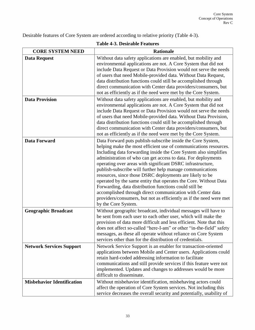
Core System
Concept of Operations
Rev C
33
Desirable features of Core System are ordered according to relative priority (Table 4-3).
Table 4-3. Desirable Features
CORE SYSTEM NEED Rationale
Data Request Without data safety applications are enabled, but mobility and
environmental applications are not. A Core System that did not
include Data Request or Data Provision would not serve the needs
of users that need Mobile-provided data. Without Data Request,
data distribution functions could still be accomplished through
direct communication with Center data providers/consumers, but
not as efficiently as if the need were met by the Core System.
Data Provision Without data safety applications are enabled, but mobility and
environmental applications are not. A Core System that did not
include Data Request or Data Provision would not serve the needs
of users that need Mobile-provided data. Without Data Provision,
data distribution functions could still be accomplished through
direct communication with Center data providers/consumers, but
not as efficiently as if the need were met by the Core System.
Data Forward Data Forward puts publish-subscribe inside the Core System,
helping make the most efficient use of communications resources.
Including data forwarding inside the Core System also simplifies
administration of who can get access to data. For deployments
operating over areas with significant DSRC infrastructure,
publish-subscribe will further help manage communications
resources, since those DSRC deployments are likely to be
operated by the same entity that operates the Core. Without Data
Forwarding, data distribution functions could still be
accomplished through direct communication with Center data
providers/consumers, but not as efficiently as if the need were met
by the Core System.
Geographic Broadcast Without geographic broadcast, individual messages will have to
be sent from each user to each other user, which will make the
provision of data more difficult and less efficient. Note that this
does not affect so-called ―here-I-am‖ or other ―in-the-field‖ safety
messages, as these all operate without reliance on Core System
services other than for the distribution of credentials.
Network Services Support Network Service Support is an enabler for transaction-oriented
applications between Mobile and Center users. Applications could
retain hard-coded addressing information to facilitate
communications and still provide services if this feature were not
implemented. Updates and changes to addresses would be more
difficult to disseminate.
Misbehavior Identification Without misbehavior identification, misbehaving actors could
affect the operation of Core System services. Not including this
service decreases the overall security and potentially, usability of

Core System
Concept of Operations
Rev C
34
CORE SYSTEM NEED Rationale
a Core System service. Communications could still be enabled
without Misbehavior Identification, but the level of trust between
users may be compromised. This should not affect safety, but may
affect mobility convenience applications, particularly those
requiring financial transactions.
Core System Service Status Core System Service status help set user expectations. Without
these capabilities, communication resource use may be adversely
affected as applications attempt to access services that may not be
available. System User interactions would still be enabled, but
management of user expectations will be difficult.
4.4 Changes Considered but not Included
A feature that was considered, but not included, was long-term storage of probe data within the Core
System. There was little input from workshops, and no input from any other forum indicating that the
Core System must provide long-term storage. This is not to say that the Core System has no storage ca-
pability; many of the needs described above will require some form of storage in order to operate. Addi-
tionally, the Communications Layer may incorporate some buffering, which could include short-term
storage of probe data, in order to accommodate various backhaul topologies.
Various ―<user> must provide <data>‖ needs were considered, but ultimately rejected as they would re-
sult in the imposition of requirements on systems outside the bounds of the Core System. Instead, criti-
cal data provisions are identified as constraints on the ability to deliver application benefit, and reflected
in discussion of policies.
A Core System service that maintained a listing of application availability across geographic bounds,
with understanding of communications performance requirements was considered. This service would
allow Mobile and Field users to determine where applications would function in advance of entering that
area. It was not included in the Core because it is an application-centric function; the burden on setting
user expectations for application performance is on the application, not the Core.
A Core System service that allowed a System User to query if another System User was permitted a spe-
cified action was considered. This could be used to support application permissions, for example deter-
mining if a Mobile User that sent a signal pre-emption message was entitled to do so. This functionality
was not implemented because many of the applications that would use this service would require low-
latency response that may make such a query impractical, and also because this is primarily an applica-
tion support function, not a Core function.
Lastly, the establishment of a back office brokerage function within the Core System was considered.
This would allow Center data providers to advertise available data for acquisition by other Centers, and
enable the establishment of a data exchange relationship between the two Centers. The rationale for in-
cluding this functionality is that advertisement of available information is a sizeable barrier to informa-
tion exchange between 3rd parties, and that providing this functionality would facilitate the development
of data exchange standards (not the message sets, which are already mature, but how to set up the ex-
changes in the first place) and remove some of the barriers to interaction amongst users, providing a
richer, more interrelated secondary data market. Ultimately, it was deemed that while this brokerage
would be a valuable service, its inclusion does not help meet any of the USDOT‘s transportation im-

Core System
Concept of Operations
Rev C
35
provement goals. The provision of a center-to-center brokerage service is thus deemed a market oppor-
tunity, but not Core System functionality.
4.5 Constraints and Assumptions
This section describes any assumptions or constraints applicable to the changes and new features identi-
fied in this section.
A constraint is ―a factor that lies outside, but has a direct impact on, a system design effort. Constraints
may relate to laws and regulations or technological, socio-political, financial, or operational factors.‖
The following are Core System constraints:
1. Privacy limits the uses of personal information as defined in the VII Privacy Policies Framework.
This document has not been updated since the VII program, but has not been disavowed either.
Since it documents concerns and policies relevant to securing, storing and handling personally
identifiable information that would be collected using or enabled by Core System facilities, its
principles still apply.
2. The IEEE 1609.x family of standards (including 1609.1, 1609.2, 1609.3 and 1609.4) will serve as
the interface standards for 5.9GHz DSRC. This program will use of standards to document inter-
faces, and the existing IEEE 1609.x standards address many of the anticipated needs for DSRC
communications. Developing a new set of DSRC communications standards would be a significant
effort.
3. X.509 certificates will provide the basis for Core and System User non-DSRC certificates. Existing
certificate management systems use X.509. Establishing new certificate formats, management pro-
cedures and implementations would be time consuming and expensive.
4. The SAE 2735 standard will serve as the basis for messages sent to and from Mobile users. The ex-
isting standard documents much of the messaging expected to Mobile users. It is the product of
much intellectual capital applied during the VII program. While it may require revision to support
Mobile cellular communications, it includes many of the concerns that are relevant for vehicles us-
ing DSRC.
5. Most existing public sector transportation agencies cannot afford additional personnel. This was
consistent input from public sector personnel at User Needs workshops.
6. If a Core System service requires geo-referencing, the same geo-referencing capabilities must be
available to all system users. If not, it will be difficult or impossible to coordinate location refer-
ences, jeopardizing safety and mobility applications that depend on accurate positioning data. POC
positioning tests and CICAS-V testing both demonstrated the need for consistent geo-location ref-
erences.
7. Service performance characteristics are constrained by the communications mechanism with which
users connect to Core System. The Core can make set minimum performance standards for usage
of Core services, but is constrained by what is available. Unless DSRC field infrastructure is dep-
loyed at a pace sufficient to keep up with Core and Mobile deployments, usage of existing com-
munications infrastructure, particularly 3G and 4G cellular, will be required to deliver services.
8. Interfaces between the Core System and System Users must be defined as open standards. This
was consistent input at the User Needs workshops.
9. IPv6 will provide the basis for communications between System Users not communicating directly
with DSRC. IPv4 will not be supported, as it is being phased out in favor of IPv6, albeit slowly.
IPv4 support was included as part of the POC, and while functional did add significant complexity.
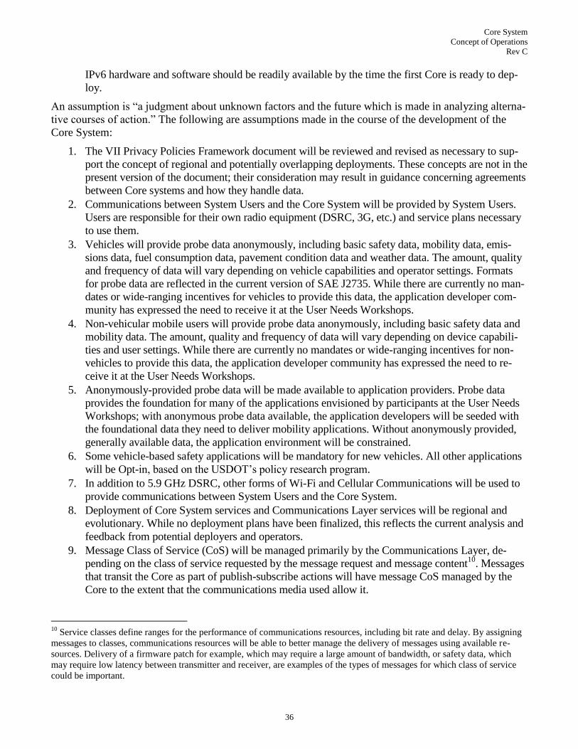
Core System
Concept of Operations
Rev C
36
IPv6 hardware and software should be readily available by the time the first Core is ready to dep-
loy.
An assumption is ―a judgment about unknown factors and the future which is made in analyzing alterna-
tive courses of action.‖ The following are assumptions made in the course of the development of the
Core System:
1. The VII Privacy Policies Framework document will be reviewed and revised as necessary to sup-
port the concept of regional and potentially overlapping deployments. These concepts are not in the
present version of the document; their consideration may result in guidance concerning agreements
between Core systems and how they handle data.
2. Communications between System Users and the Core System will be provided by System Users.
Users are responsible for their own radio equipment (DSRC, 3G, etc.) and service plans necessary
to use them.
3. Vehicles will provide probe data anonymously, including basic safety data, mobility data, emis-
sions data, fuel consumption data, pavement condition data and weather data. The amount, quality
and frequency of data will vary depending on vehicle capabilities and operator settings. Formats
for probe data are reflected in the current version of SAE J2735. While there are currently no man-
dates or wide-ranging incentives for vehicles to provide this data, the application developer com-
munity has expressed the need to receive it at the User Needs Workshops.
4. Non-vehicular mobile users will provide probe data anonymously, including basic safety data and
mobility data. The amount, quality and frequency of data will vary depending on device capabili-
ties and user settings. While there are currently no mandates or wide-ranging incentives for non-
vehicles to provide this data, the application developer community has expressed the need to re-
ceive it at the User Needs Workshops.
5. Anonymously-provided probe data will be made available to application providers. Probe data
provides the foundation for many of the applications envisioned by participants at the User Needs
Workshops; with anonymous probe data available, the application developers will be seeded with
the foundational data they need to deliver mobility applications. Without anonymously provided,
generally available data, the application environment will be constrained.
6. Some vehicle-based safety applications will be mandatory for new vehicles. All other applications
will be Opt-in, based on the USDOT‘s policy research program.
7. In addition to 5.9 GHz DSRC, other forms of Wi-Fi and Cellular Communications will be used to
provide communications between System Users and the Core System.
8. Deployment of Core System services and Communications Layer services will be regional and
evolutionary. While no deployment plans have been finalized, this reflects the current analysis and
feedback from potential deployers and operators.
9. Message Class of Service (CoS) will be managed primarily by the Communications Layer, de-
pending on the class of service requested by the message request and message content10
. Messages
that transit the Core as part of publish-subscribe actions will have message CoS managed by the
Core to the extent that the communications media used allow it.
10
Service classes define ranges for the performance of communications resources, including bit rate and delay. By assigning
messages to classes, communications resources will be able to better manage the delivery of messages using available re-
sources. Delivery of a firmware patch for example, which may require a large amount of bandwidth, or safety data, which
may require low latency between transmitter and receiver, are examples of the types of messages for which class of service
could be important.

Core System
Concept of Operations
Rev C
37
10. Message priority will be managed primarily by the Communications Layer, considering factors
such as the priority requested by a message, message content and available resources11
. Messages
that transit the Core as part of publish-subscribe actions will have message priority managed by the
Core to the extent that the communications media used allow it.
11
Prioritization will increase the likelihood that more important messages are given access to communications resources, and
increase the chance that they are sent and received relative to less important messages. Messages carrying safety information
for example, would be prioritized higher than messages carrying probe data.

Core System
Concept of Operations
Rev C
38
5.0 CONCEPTS FOR THE PROPOSED SYSTEM
This section describes the Core System that will be developed to satisfy the needs defined in Section 4.0.
The Core System may be thought of as housing the functionality to manage the interfaces between Sys-
tem Users.
The Core System includes eight distinct subsystems:
1. Core2Core, which manages interactions between Core Systems, coordinating backup and service
handoffs between Cores.
2. Data Distribution, which informs data providers of how to provide data, manages data subscrip-
tions, and provides data forwarding capabilities. This includes the notion of publish-subscribe.
3. Misbehavior Identification, which identifies and suggests action against misbehaving System
Users.
4. Network Services, which provides the information necessary to enable communications between
specific System Users.
5. Service Monitor, which monitors the state of Core System components and makes the informa-
tion available to System Users.
6. Time, which keeps Core System services operating on the same time base as System Users.
7. User Permissions, which manages roles and responsibilities of System Users.
8. User Security, which manages credentials of System Users.
Data Distribution, Service Monitor, Misbehavior Identification, Network Services, User Permissions and
User Security provide services to System Users. Core2Core provides services to other Cores. Service
Monitor provides additional services related to performance and operations to Core Personnel. The Time
subsystem offers no external services.
In addition, the Core System may procure services from External Support Systems that provide services
the Core needs to deliver, but make more sense to manage, maintain and share between multiple Cores
due to overriding performance or functional constraints. The most likely candidate for external support
is an external Certificate Authority, due to the need to coordinate certificate distribution and revocation
activities between all cores. No other functions so plainly require all Cores to interact, so other External
Support Systems are less likely.
The reader is encouraged to resist the temptation to think of the Core System as some physical system
purchased and installed once but rather a set of services, implemented in a distributed fashion, both in
time and geography. The structure will be provided by the requirements on the system performance and
through use of standardized interfaces.
As described in Section 4.1, the Communications Layer provides communications between the services
provided by the Core System and the safety, mobility, and environmental applications implemented by
Mobile, Center and Field users. The Communications Layer could be implemented by private or public
operators, but in either case must support the privacy policies approved by USDOT which are currently
documented in the VII Privacy Policies Framework.
The subsections that follow describe the proposed system starting with the background and overall scope
of the Core System and some of the operational policies and constraints that will guide the use of the
system. Then the system will be described in terms of its subsystems and how those subsystems interact

Core System
Concept of Operations
Rev C
39
with each other and the outside world. This will then be followed by a description of the various modes
of operation supported by the Core System, the users or actors that interact with the Core System, and
the support environment that surrounds and sustains the Core System.
5.1 Background, Objectives and Scope
This section describes the background and motivations that are behind the definition of the new system.
What events have led to the formation of the new Core System? What changes have taken place in the
industry and in areas of research that have driven the definition of the Core System?
Throughout this ConOps a distinction is made between the applications that are visible to users (travel-
ers, operators, planners, advertisers, etc) and the services of the Core System that support those applica-
tions. To understand how the Core System is to be organized, this section looks at the evolution of the
USDOT‘s programs that are related to the development of the connected vehicle environment.
When the USDOT re-branded the VII initiative in early 2009, it involved more than just changing the
name of the initiative. The USDOT also changed some of the basic assumptions related to how mobile
and infrastructure components of the system would communicate. The overall program is no longer fo-
cused on a name or brand, but the changes identified around the time of the re-branding remain. One
major change relaxed the constraint that all wireless communications would use DSRC radios and pro-
tocols.
The technologies and applications that will be deployed as part of this program can transform travel as
we know it. Combining leading edge technologies such as advanced wireless communications, on-board
computer processing, advanced vehicle-sensors, navigation, and smart infrastructure can provide the ca-
pability for travelers to identify threats, hazards, and delays on the roadway and to communicate this in-
formation over wireless networks to provide alerts, warnings, and real time road network information.
This program makes use of wireless communications networks that use both V2V and V2I communica-
tions to support the cooperative system capabilities necessary to support the applications. Within ve-
hicles, four types of devices are supported: embedded devices (devices that are installed as part of the
vehicle‘s systems by the vehicle manufacturer), retro-fit devices (devices installed after the vehicle
leaves the vehicle manufacturer, but which connect to in-vehicle information systems), aftermarket de-
vices (devices that are installed either at the time of vehicle purchase or later, that are not necessarily
connected to in-vehicle information systems but can be, at the vehicle owner‘s option), and ―carry-in‖
devices (devices that can be temporarily installed in vehicles and are not necessarily connected to in-
vehicle information systems). ―Carry-in‖ devices include the category of hand-held devices (e.g., smart
phones) that could also be carried by pedestrians or other users of the roadways (e.g., bicyclists or
wheelchair-bound travelers). Communications to and from each of these types of devices will be sup-
ported whether the communications is one-way or two-way and whether the communication is between
any combination of vehicles, infrastructure and mobile devices.
The ability to collect, process and exchange real-time data provides travelers with an opportunity for
greater situational awareness of the events, potential threats, and imminent hazards within their envi-
ronment. When combined with technologies that intuitively and clearly present alerts, advice, and warn-
ings, travelers can make better and safer decisions. Additionally, the connected vehicle environment will
provide the opportunity to enhance the efficacy of automated vehicle-safety applications.
As a means of ensuring public acceptance of these technologies, the National VII Coalition developed a
Vehicle Infrastructure Integration Privacy Policies Framework which is designed to protect the public
from any misuse of PII (Personally Identifiable Information) that might be collected.

Core System
Concept of Operations
Rev C
40
Since the USDOT‘s initiation of VII, international projects have provided different concepts and ap-
proaches to the wireless vehicle environment and the applications that are possible with connected ve-
hicles. These projects include: Communications for eSafety (COMeSafety), Co-operative Systems for
Intelligent Road Safety (COOPERS), the Cooperative Vehicle-Infrastructure Systems (CVIS) program,
the Car 2 Car consortium, Japanese projects such as Smartway, as well as the Communications Access
for Land Mobiles (CALM) standards effort in International Organization for Standardization (ISO)
Technical Committee (TC) 204 Working Group (WG) 16.
The lessons learned from other parts of the world provide input to the definition of the transportation
safety, mobility, and environmental applications for the US and North America. The Core System will
also use the international efforts in the definition of the requirements and architecture, building upon
their success in the vehicle to roadside wireless environment. The concepts for the framework of the
Core System described in this ConOps are consistent with the high-level concepts and organization in
the European Framework architecture. One difference that has already been shown is that the Core Sys-
tem merges the Vehicle and other mobile devices into the same category as it concerns the interaction
with transportation applications. Other differences will come out as the system is architected in subse-
quent phases just as similarities will be manifested in architectural structures that build upon work al-
ready accomplished in previous work, including the international community.
5.2 Operational Policies and Constraints
This section describes operational policies and constraints that are to be considered for the Core System.
Operational policies are predetermined management decisions regarding the operations of the system.
Policies limit decision-making freedom but do allow for some discretion. Operational constraints are
limitations placed on the operations of the system. This section will discuss topics such as ―why should a
data provider provide data‖, interface standardization, data production, distribution vs. services, data
ownership, and deployment policies.
While the policy and governance of the Core System is being considered as part of the architecture, most
of the operational policies are being worked separately12
. A few policy issues that will directly affect the
system architecture are reflected in assumptions or constraints in Section 4.5. There are also operational
policies and constraints that will have to be considered as part of the architecture definition. These issues
are shown here as a way to ensure they are considered throughout the system definition process but also
so that readers considering the deployment of Core System components will be aware of them.
Certification:
Devices will have to be certified that they meet the specifications defined for interaction within the
system. An entity or entities, granted authority by the USDOT and respected by the state and local
DOTs and vehicle manufacturers, will have to oversee this certification process.
Similarly for software, there should be a means by which an authority can certify that the applica-
tions meet national standards for application behavior wherever they are deployed.
Exactly which devices and software need to be certified is uncertain. Safety of life devices and
software almost certainly need to be certified, but which, if any, other devices and software need to
be certified is uncertain. Mechanisms should be established to facilitate certification so that the ac-
tual practice of certification does not constrain the policy decision of what needs to be certified.
12
See http://www.its.dot.gov/connected_vehicle/connected_vehicle_policy.htm for details on policy research sponsored by
USDOT.

Core System
Concept of Operations
Rev C
41
Operations and Maintenance:
A constraint that will be particularly felt by the public sector agencies that will be hosting and op-
erating Core System elements is that they may have limited ability to hire and train qualified staff.
The operation of the Core System may become part of ―other duties as assigned‖ to their existing
personnel. It will be a challenge to ensure the system is functional without compromising system
security and integrity. There may be a need to have additional staff, perhaps contracted, during the
early phases of deployment until the Core System and the applications can replace services they
currently run.
Security Management:
The management of digital certificates required for wireless communications will need to assure
national interoperability. Some entity or entities, granted authority by the USDOT and recognized
by the state and local DOTs and vehicle manufacturers, will have to manage these digital certifi-
cates. At a minimum this will include four different types of certificates: identity DSRC certifi-
cates, anonymous DSRC certificates, X.509 Core System certificates, and X.509 non-DSRC Sys-
tem User certificates. Digital certificates are issued by a Certificate Authority (CA) and identify the
owner (name and a serial number, or pseudonym for anonymous Mobile Users), expiration dates, a
copy of one of the certificate holder's public keys (one key used for encrypting and decrypting
messages another key for digital signatures), and the digital signature of the certificate-issuing au-
thority so that a recipient can verify that the certificate is real13
. There is an ongoing research effort
to define the certificate management policy. The benefit of having USDOT involved along with the
public and private sector is that it increases the likelihood that a consistent practice can be estab-
lished and this critical portion of the system will succeed.
Identification of misbehaving users will require communication between every Core System, or at
least a proxy communication with each Core communicating to the same certificate management
entity. This will also require some coordination, as one locality‘s misbehavior may not be the same
as another‘s. For example, one locality may wish to revoke permissions for misbehaving users,
while another would not. This leads to a situation where a misbehaving user may still participate in
the connected vehicle environment, might lose his permissions in one or more localities but main-
tain them in others.
Definition of user groups will simplify operations, but if definitions vary between Core Systems,
interactions between System Users and Cores could yield different results which could lead to end
user confusion or dissatisfaction. User group definitions and permission sets should be coordinated
between Cores operating where System Users may interact with both. Core2Core interactions
should enable modifications to user group definitions once user groups have been agreed to by the
entities operating their respective Cores.
Data Provision/Ownership:
Determination of who owns data produced by mobile devices, including probe data, will affect
deployments and secondary markets. This policy area may be addressed in ways that are consistent
with current practices for data sharing agreements of ITS deployments in metropolitan areas today.
Issues of ownership may also need to be settled via policy to ensure that public agencies seeking to
manage their transportation operations have access to data that may be available this program‘s ap-
13
Many Mobile Users will not require encryption keys, but will require the ability to digitally sign messages. Different keys
should be used for encryption vs. signing.

Core System
Concept of Operations
Rev C
42
plications while at the same time preserving the investment that other agencies or a private entity
may have put into the collection of that data.
Incentives may be needed from the data collectors – those users that are seeking traffic conditions,
weather, other traveler related data – in order for travelers to ‗opt-in‘ to a service whereby they
provide such rich information.
System Performance Management:
Policies and procedures for revocation of certificates for devices that fall outside the standards of
operation will have to be developed. This includes devices that are malfunctioning in some way
but are still transmitting potentially erroneous messages to other System Users (e.g. Field Users
transmitting incorrect weather data due to a faulty sensor, or Mobile Users transmitting incorrect
safety messages due to a positioning error) or devices that have been deliberately tampered with
that could cause confusion or threaten the safety and security of other users. The Core System will
include functions to monitor the behavior of devices and applications interacting with and through
the Core System to identify activity that might indicate a risk to the connected vehicle environ-
ment.
The development of these policies and procedures must be nationally consistent and these policies
and procedures need to be accepted and implemented everywhere the system is deployed. Other-
wise security standards could vary depending on the Core which could compromise the environ-
ments managed by other more secure Cores.
Flexibility:
The deployment strategy has not been finalized. System requirements, architecture, operational
policies must all consider multiple deployment options.
Economic conditions may dictate the deployment strategy and the architecture and governance
constraints will need to be compatible with a wide range of deployment options.
5.3 Description of the Proposed System
The diagram shown below in Figure 5-1 illustrates the context in which the Core System operates. The
Core System includes eight subsystems (defined in section 5.3.2). It interacts with Field, Mobile and
Center Users, other Cores, External Support Systems and Core System Operators. The logical interfaces
that connect System Users to Core services will be defined later in this section.

Core System
Concept of Operations
Rev C
43
Core
SystemMisbehavior
Identification
Network
Services
Data
Distribution
User Security
User
Permissions
Service
Monitor
Core2Core
Time
Center Users
Operators
Other Cores
Field Users
Mobile Users
External Support
Systems
Figure 5-1. Core System Subsystem Context
5.3.1 The Operational Environment
The operational environment in which the Core System exists is a heterogeneous community of systems
run by multiple agencies at different levels of complexity and various locations. Some examples of the
operational environment can be gleaned from the representative scenarios in Section 6.0 of this docu-
ment. The potential number of scenarios involving transportation-related system users is unlimited but
all will involve some sort of wireless communication. Applications may be deployed in complex confi-
gurations supporting a major metropolitan area or a minimal configuration to support a set of isolated
rural road curve warning systems.
As Core Systems are deployed some may include just the essential functions to support a particular local
area and rely on an interface to another Core to provide additional services. For instance, one Core could
include the necessary hardware and software to manage a subset of the subsystems for their local area
and rely on a connection to another Core‘s subsystems for additional services. A larger Core implemen-
tation may include instances of all of the subsystems. It would still need a connection to other Cores to
support the security services as new mobile users came into their region.
The Core System will not necessarily require a control center with large video screens or employ a large
number of operators. A Core can function in an office or data center environment as long as there is
access to a network that enables communications between System Users and the Core.
The Core System may have different deployment configurations:

Core System
Concept of Operations
Rev C
44
Standalone system – where the deploying agency (public or private) includes all hardware, soft-
ware and communications necessary to support their services in an office or center environment
that is dedicated to support safety, mobility, and environmental applications.
Collocated with other transportation services – where the deploying agency (public or private) in-
stalls the hardware, software, communications in an office or center environment that is also used
to house the operations for another transportation service such as a traffic management center or a
traveler information service provider
Distributed across geographic locations, including remote hosting – where one deploying agency
has the hardware and software for part of the services but uses internet communications to run
some Core System services remotely, either at another facility owned by the same agency, another
similar agency, or a software as a service (SaaS) provider for some utilities.
A Core System‘s deployment footprint is made up of the geographic area over which it provides services,
what services it provides, and a measure of the performance of those services over the service area. Service
performance will be a factor of several items: performance of the hardware and software on which the ser-
vice operates, but most significantly the communication path over which the service is accessed by the
System User. Hardware can usually be scaled to improve performance, but deployment of higher speed or
lower latency wireless communications is a more lengthy process. Consequently, the performance aspect
of service delivery will be primarily constrained by the performance of wireless communications available
in the deployment area. This mostly affects Mobile users, since Field and Center users usually have access
to wireline communications offering performance sufficient to their needs.
Further complicating the operational environment is the relationship between Cores. Some Cores may not
offer all desirable services, and some operating in the same area may handle different types of data, de-
pending on policy decisions related to data ownership.
Isolated Core systems provide the baseline for illustrating Core operational environments. In this example
a single Core provides services for a given geographic area. This area has 3G cellular services available
throughout, as well as two subsets where DSRC-based roadside equipment is deployed. Core services are
available through 3G everywhere, and through DSRC (to backhaul of some type, could be wired or wire-
less) in those two smaller areas.
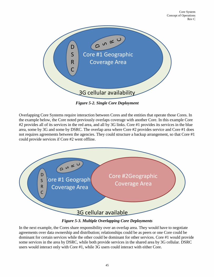
Core System
Concept of Operations
Rev C
45
3G cellular availability
Core #1 Geographic Coverage Area
DSRC
Figure 5-2. Single Core Deployment
Overlapping Core Systems require interaction between Cores and the entities that operate those Cores. In
the example below, the Core noted previously overlaps coverage with another Core. In this example Core
#2 provides all of its services in the red area, and all by 3G links. Core #1 provides its services in the blue
area, some by 3G and some by DSRC. The overlap area where Core #2 provides service and Core #1 does
not requires agreements between the agencies. They could structure a backup arrangement, so that Core #1
could provide services if Core #2 went offline.
3G cellular available
Core #1 Geographic Coverage Area
DSRC
Core #2Geographic Coverage Area
Figure 5-3. Multiple Overlapping Core Deployments
In the next example, the Cores share responsibility over an overlap area. They would have to negotiate
agreements over data ownership and distribution; relationships could be as peers or one Core could be
dominant for certain services while the other could be dominant for other services. Core #1 would provide
some services in the area by DSRC, while both provide services in the shared area by 3G cellular. DSRC
users would interact only with Core #1, while 3G users could interact with either Core.

Core System
Concept of Operations
Rev C
46
3G cellular available
Core #1 Geographic Coverage Area
DSRC
Core #2Geographic Coverage Area
Shar
ed
Figure 5-4. Multiple Overlapping Core Deployments with Shared Service
These examples illustrate some of the potential for overlap and shared service between Cores in a mixed
communications environment. Interaction between Cores is necessary when Mobile users request services
offered by one and not another in a shared space, and also when Mobile users move between coverage
areas, at least to coordinate operational boundaries. These interactions will be more fully described in the
System Architecture document. For now what matters is that there can be many Core systems, they will
have to interact, and they use a variety of communications media.
One last result of this analysis illustrates a remarkable difference from the architecture conceived in the
past: A Core System can be deployed without DSRC field equipment. DSRC field equipment will enable
many applications including V2I safety applications, but V2V interactions rely only on the Core‘s facilita-
tion of trust relationships. This does not necessarily require DSRC-enabled field equipment.
5.3.2 Major Subsystems
This section describes the subsystems of the Core System, how they relate to the Needs that were de-
fined in Section 4.0, and how they relate to each other to support the overall operation of the Core Sys-
tem.
While at this point in the system engineering process it is premature to fully develop the major system
components some high-level concepts can be related. The Core System is all about standardized com-
munication that satisfies System User application needs. The Core System and the overall framework of
applications need to be flexible to allow for staged deployments both large and small. The Core is really
just enabling communications between System Users and as such is only comprised of standardized in-
terfaces and the services required to make the interfaces work. The interfaces must be standardized in
order to permit interoperability among the external systems described in Section 5.3.3.
The services will be further defined as the engineering process transitions from asking ―what is it‖ to
answering ―how does it do it?‖
Throughout the subsystem descriptions the term ―System User‖ is used to identify the applications or
external systems (i.e., mobile, center, and field) that are interacting with the Core System. The only hu-

Core System
Concept of Operations
Rev C
47
man users of the Core System are the administrative type personnel that operate and maintain the inter-
nal Core System services.
5.3.2.1 Subsystem Descriptions
This section provides a description of each of the subsystems of the Core System, arranged alphabetical-
ly. A subsystem is defined as an integrated set of components that accomplish a clearly distinguishable
set of functions with similar or related uses14
.
Core2Core Subsystem: The Core2Core Subsystem interfaces with other Core Systems, advertising its
jurisdictional scope, offered services and services it desires from other Cores. The Core2Core subsystem
will maintain knowledge base of data and services available among other Cores. In this way, the Core
can act as a user to another Core, providing proxy services that it does not offer but another does. Addi-
tionally, Core2Core is responsible for compatibility between Cores, ensuring that it does not encroach
on the scope of another Core, and similarly accepting error messages from Mobile Users that might in-
dicate a cross-jurisdictional compatibility or scope coverage issue. Interfaces between Cores will be
formalized in interfaces specifications. Conflicts and discrepancies between Cores will have to be re-
solved by agreements between the agencies responsible for the respective Cores.
Data Distribution Subsystem: The Data Distribution Subsystem maintains a directory of System Users
that want data and facilitates the delivery of that data to those users. It supports multiple distribution me-
chanisms, including:
Source-to-Points: The data provider communicates data directly to data consumers. In this case, no
data is sent to the Core System, however the Core is involved to check User Permissions and pro-
vide addressing services through those subsystems
Publish-Subscribe: The data provider communicates data to the Data Distribution subsystem,
which forwards it to all users that are subscribed to receive the data.
Data Distribution allows data consumers to specify (and change the specification of) data they wish to
receive using criteria including:
Data type
Data quality characteristics
Data format requirements
Geographic area
Sampling rate
Minimum and maximum frequency of data forwarding
Data Distribution maintains a registry of which data consumers get what data, according to the criteria
defined above. Data Distribution does not store or buffer data beyond that which is necessary to com-
plete publish-subscribe actions. If a given data consumer is unable to receive data that it has subscribed
to because of a communications or other system failure, the data in question may be lost. The degree to
which data distribution buffering accommodates connectivity failures will be up to the Core System dep-
loyment. Some Cores may offer ―temporary storage‖ in this fashion.
14
INCOSE Systems Engineering Handbook v3.1, The Hierarchy within a System, Appendix E-1.

Core System
Concept of Operations
Rev C
48
Data Distribution repackages data it receives from data providers, stripping away the source header in-
formation while maintaining the message payload. It then sends the repackaged payload data to sub-
scribers of that data.
Data Distribution does not share or exchange data with other Core Systems. System Users that want data
from multiple Cores need to subscribe to each Core.
Misbehavior Identification Subsystem: The Misbehavior Identification Subsystem analyzes messages
sent to the Core System to identify users operating outside of their assigned permissions. It works with
the User Permissions subsystem to identify suspicious requests and to maintain a record of specifically
identifiable users that:
1. Provide false or misleading data
2. Operate in such a fashion as to impede other users
3. Operate outside of their authorized scope
Because most end users will rarely interface with the Core System, Misbehavior Identifier will also ac-
cept reports of misbehaving users from other users. Center, Mobile and Field users can send misbeha-
vior reports that reference credentials attached to messages, and note the type of misbehavior in ques-
tion. Misbehavior Identifier will record such reports, and according to a set of Core Personnel-controlled
rules, determine when to revoke credentials from such reported misbehaving users. For anonymous us-
ers revocation is more complex, and may result instead in a lack of credential renewal. Large numbers of
failed renewals could have a significant effect on operations; system requirements and design activities
will need to ensure that renewal failures do not adversely affect system performance or user experience.
Network Services Subsystem: The Network Services Subsystem provides information to System Users
and Core System services that enable communication between those users and services. The Network
Services subsystem will provide the information necessary for users to communicate with other users
that have given permission to be communicated with. Network Services will also provide the informa-
tion necessary to enable users to communicate with a group of users, by maintaining information regard-
ing available communications methods, addresses, performance characteristics for geo-cast communica-
tions.
Network Services will also provide management for Communications Layer resources. It will enable
decisions about which communications medium to use when more than one is available. This includes
identifying available communications methods current performance characteristics and applicable user
permission levels. Permission requirements will be coordinated with the User Permissions subsystem.
Service Monitor Subsystem: The Service Monitor Subsystem monitors the status of Core System ser-
vices, interfaces, and communications networks connected to the Core. It informs System Users of the
availability and status of its services.
Service Monitor also monitors the integrity of internal Core System components and supporting soft-
ware and mitigates against vulnerabilities. This includes periodic verification of the authenticity of Core
service software and supporting software. This also includes monitoring for vulnerabilities including but
not limited to virus protection, network port monitoring and monitoring for patches to third party com-
ponents. Should a vulnerability be detected, or a component of the Core found to have lost integrity,
Service Monitor takes steps to mitigate against damage and performance degradation.
The Service Monitor Subsystem ensures the physical security of Core System services by monitoring the
environmental conditions that Core components operate in (temperature, humidity) as well as the condi-

Core System
Concept of Operations
Rev C
49
tion of its power system. It takes steps to mitigate against system failures in the event that environmental
conditions exceed operating thresholds. Actions could include the activation of environmental or backup
power systems and/or the modification of Core service operations, as well as Core Personnel notifica-
tion.
Service Monitor also monitors the performance of all services and interfaces and makes performance
metrics available to Core Personnel.
Time Subsystem: The Time Subsystem uses a time base available to all System Users and makes this
time available to all Core System services which use this time base whenever a time reference is re-
quired.
User Permissions Subsystem: The User Permissions Subsystem provides tools allowing System Users
to verify whether a given user, identified by digital certificate-based credentials, is authorized to request
or perform the action requested in the message payload. It also maintains the status of users, whether
they have a specific account, their allowed behaviors (publish, subscribe, actions allowed to request,
administrate, etc.) with defined permissions or belong to an anonymous group. User Permissions pro-
vides tools for Core Personnel to create new users and groups, modify existing users and groups, and
modify permissions associated with users and groups.
User Security Subsystem: The User Security Subsystem manages access rules and credentials in the
form of digital certificates, including X.509, 1609.2 identity and 1609.2 anonymous certificates, for all
System Users and Core System components that require and are entitled to them. It creates and distri-
butes cryptographic keys to qualifying System Users. It works with User Permissions to determine
whether a given user applying for credentials or keys is entitled to them. It also manages revocation of
credentials, distributing Certificate Revocation Lists (CRLs) of obsolete or disallowed credentials to in-
terested System Users. User Security may use an External Support System to manage certificates, but
such a determination is a design decision and will be deferred until the system architecture is defined.
5.3.2.2 Subsystem to Needs
Table 5-1 shows the relationship between the Core System Subsystems and the needs defined in Section
4.0. In most cases a subsystem will satisfy multiple needs and in some cases needs may be satisfied in
multiple subsystems.
Table 5-1. Subsystem to Needs Traceability Matrix
Core Subsystem Needs
Core2Core Subsystem Core System Independence, Core System Interoperability, Core
System Interdependence
Data Distribution Subsystem Data Request, Data Provision, Data Forward, Geographic Broadcast,
Core System Interoperability, Core System Interdependence
Misbehavior Identification
Subsystem
Misbehavior Identification, Core Trust Revocation, System User Trust
Revocation, Core System Interoperability, Core System
Interdependence
Network Services Subsystem Network Services Support, Geographic Broadcast, Core System
Interoperability, Core System Interdependence
Service Monitor Subsystem Core System Service Status, System Integrity Protection, System
Availability, System Operational Performance Monitoring, Core
System Independence, Core System Interoperability

Core System
Concept of Operations
Rev C
50
Time Subsystem Time Base, Core System Interoperability, Core System
Interdependence
User Permissions Subsystem Authorization Verification, Authorization Management, Core System
Independence
User Security Subsystem Data Protection, Core Trust, System User Trust, Core Trust
Revocation, System User Trust Revocation, Core System
Independence, Core System Interoperability, Core System
Interdependence
5.3.2.3 System User - Subsystem Interfaces
The following diagrams and descriptions illustrate which
subsystems System Users and other Cores interact with.
The legend at right documents the color coding used on
these diagrams.
Figure 5-5 shows the subsystems that Mobile Users inte-
ract with. User Security provides certificates to qualified
Mobile Users. User Permissions accepts credentials from System Users, and verifies that a given Mobile
User is entitled to the action he is attempting. Data Distribution accepts registration requests, subscrip-
tion requests and data from Mobile Users, and provides data to subscribed Mobile Users. Network Ser-
vices accepts queries for and provides network connectivity information, such as IP addresses. Service
Monitor provides the status of Core services. Misbehavior Identification accepts suspicious behavior
information from Mobile Users.
Other User
User Focus
of diagram
External
Support
Subsystem
interacted with
Subsystem not
interacted with
Subsystem interacted
with by proxy
Legend
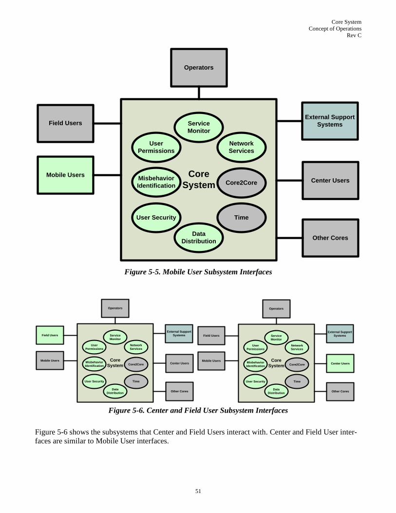
Core System
Concept of Operations
Rev C
51
Core
SystemMisbehavior
Identification
Network
Services
Data
Distribution
User Security
User
Permissions
Service
Monitor
Core2Core
Time
Center Users
Operators
Other Cores
Field Users
Mobile Users
External Support
Systems
Figure 5-5. Mobile User Subsystem Interfaces
Core
SystemMisbehavior
Identification
Network
Services
Data
Distribution
User Security
User
Permissions
Service
Monitor
Core2Core
Time
Center Users
Operators
Other Cores
Field Users
Mobile Users
External Support
Systems
Core
SystemMisbehavior
Identification
Network
Services
Data
Distribution
User Security
User
Permissions
Service
Monitor
Core2Core
Time
Center Users
Operators
Other Cores
Field Users
Mobile Users
External Support
Systems
Figure 5-6. Center and Field User Subsystem Interfaces
Figure 5-6 shows the subsystems that Center and Field Users interact with. Center and Field User inter-
faces are similar to Mobile User interfaces.

Core System
Concept of Operations
Rev C
52
Core
SystemMisbehavior
Identification
Network
Services
Data
Distribution
User Security
User
Permissions
Service
Monitor
Core2Core
Time
Center Users
Operators
Other Cores
Field Users
Mobile Users
External Support
Systems
Figure 5-7. Operator Subsystem Interfaces
As shown in Figure 5-7, Operators interact with all Core subsystems to some degree. The Service Moni-
tor subsystem provides the primary interface, over which performance and status information is sent.
Operators interact with User Permissions to create and modify users, user groups and permissions. User
Security is used to configure and monitor the distribution of certificates. Misbehavior Identification re-
ports the identification of bad actors for Operator intervention if necessary. Data Distribution allows the
manual adjustment of subscriptions. Core2Core interactions allow the Operator to update the locations
and addresses of other Cores that this Core must interact with. Network Services allow the Operator to
manually configure network information. The Operator can interact with any subsystem to instantiate,
update or restart any individual subsystem.

Core System
Concept of Operations
Rev C
53
Core
SystemMisbehavior
Identification
Network
Services
Data
Distribution
User Security
User
Permissions
Service
Monitor
Core2Core
Time
Center Users
Operators
Other Cores
Field Users
Mobile Users
External Support
Systems
Figure 5-8. Other Core Subsystem Interfaces
Figure 5-8 shows that other Cores interact directly only with the Core2Core subsystem. This subsystem
manages interactions between Core subsystems and other Cores, serving as proxy for interactions with
the other subsystems. Most subsystems have interactions with other Cores. Service Monitor may pass
along service status and the need for sharing services in case a subsystem enters a lower performing
state (see the discussion on states later in this section). Network Services coordinate data to maintain
consistency. Data Distribution coordinates subscriptions and registrations for boundary conditions, so
Cores are consistent in who collects and distributes data over what area (not propagating subscriptions).
User Security coordinates the revocation of certificates and ensures consistency among certificates that
are distributed, so that no duplications occur.
5.3.2.4 Subsystem - Subsystem Interfaces
Core subsystems interact extensively. Interfaces between the Core subsystems include:
1. All subsystems communicate with the Service Monitor Subsystem to exchange configuration and
performance data.
2. All subsystems receive time information from the Time Subsystem
3. User Security, Data Distribution, Network Services and Misbehavior Identification exchange user
permissions and queries of user permissions with the User Permissions Subsystem
4. User Security, Data Distribution and Network Services provide Misbehavior Information to the
Misbehavior Identification Subsystem

Core System
Concept of Operations
Rev C
54
5. Core2Core Subsystem sends proxy requests for data to User Security, User Permissions, Data Dis-
tribution, Network Services and Misbehavior Identification.
5.3.2.5 Data Stores in the Core System
The term Data Store is defined as ―a permanent storehouse of data. The term is often used to lump the
storage of all types of data structures (files, databases, text documents, etc.) into one generic category.‖15
While long term storage of data such as traffic probe data is not a service of the Core System, there will
be data stores within the system to support and manage the system services. This will include the infor-
mation necessary to communicate with other Cores, with External Support Systems, Communications
Layer systems, and will probably include data stores to organize misbehavior, states and modes, network
configurations, credential management and System User information16
. Specific details with regard to
the exact types, locations, capacities and contents of the various data stores will be covered in the design
phase of Core System development.
5.4 Modes of Operation
The states and modes of operation of the Core System are described in this section. The following list
identifies the states that will be considered1718
:
Installation (Core-wide only)
Operational
Maintenance
Training (Core-wide only)
Standby
Two or more of these states may occur simultaneously within the same Core, as different subsystems
may be in different states. Subsystems may be in any combination of Operational, Maintenance, and
Standby states. Training and Installation states are Core-wide; if the Core is in one of these two states,
all subsystems are in that state.
The major states are described in more detail below.
Installation: This state includes all pre-operational activities necessary to plan, develop, install and
verify the procedures and system configurations used to support the Core System. The Installation
state for the Core System includes the following activities:
– Planning and preparation
– Coordinating with participating external agencies
– Detailed planning of resources
– Resource acquisition
– Installation
– Preparation and verification of subsystem configurations and timelines (different configura-
tions may be applicable based on time of day, day of week etc.)
15
PC Magazine Encyclopedia, online definition - http://www.pcmag.com/encyclopedia_term/; Copyright 1996-2011 Ziff Davis, Inc. 16
For Mobile Users this information will only be collected and stored for as long as necessary in accordance with the Privacy
Policies Framework. 17
Other states may be defined as needed in later documents. 18
Depending on local policies and procedures, a particular Core System may deviate from these states. For example, a train-
ing state may not be supported at all.

Core System
Concept of Operations
Rev C
55
– System checkout (the activities necessary to ensure that the configuration of Core subsystems
and interfaces are per the planning documentation and verified ready to support operations)
– Operating the Core System in parallel with current systems. Depending on the locality, the In-
stallation state could take a few weeks/ months or, for a new locality, few months/years in du-
ration.
– System check-out
Operational: This state includes all activities during the normal conduct of operations. This state al-
so needs to be able to handle support for services from other Cores including fail-over and/or de-
graded services. The Operational state includes the following activities:
– Loading, verifying and granting security certificates to System Users
– Providing timing services
– Facilitating real-time and near real-time data exchanges
– Providing network services
– Enabling application processing
– Monitoring health of Core System
– Managing Core System resources
– Accommodating service support for other degraded or non-operational Cores
Maintenance: An administrator places the Core or a particular subsystem in a Maintenance state to
replace an impaired component or to upgrade a component(s) of the Core. Depending on the nature
of maintenance planned, the impact on the Core System‘s ability to provide services may be im-
pacted. Also, its ability to manage itself and provide visibility into how it is performing may be
impacted.
Training: The Core System will be placed in a Training state when it is used for imparting training
on the Core features. Certain features like real-time display of log messages and debug messages
may be enabled in the Training state which may not otherwise be accessible under normal condi-
tions.
Standby: The Core System or subsystem operating in a Standby state will be providing backup to
one or more other Cores or other Core subsystems. From the standby state the Core or subsystem
may take over the functions of another Core or subsystem if required. When operating in Standby
state, the Core or subsystem should be continually evaluated on its ability to switch-in and take
provide services for the Core or subsystem it is supporting.
Figure 5-9 captures the states of the Core System and the transitions possible from one state to another.

Core System
Concept of Operations
Rev C
56
stm [StateMachine] Component Model [State Transition]
Standby
Training
InstallationEntryPoint
Operational
Maintenance
Figure 5-9. Core State Transition Diagram
While in the Operational state, each subsystem may be in one of the following modes:
Normal mode: In the normal mode, there is little or no functional or performance impacts on the
ability of the subsystem to provide its services. In addition, the Service Monitor provides good vi-
sibility into how the subsystem is performing.
Degraded mode: In the degraded mode, the subsystem is impaired to a significant extent: its ability
to provide services is greatly reduced or eliminated completely. Also, Service Monitor‘s ability to
manage the subsystem may be impaired.
Restricted mode: In the restricted mode, the subsystem is capable of performing as expected; how-
ever certain services or features are disabled to support a specific event such as an evacuation. The
restriction is determined by operators/entities outside of the system and subsequently implemented
by the system in response to an authorized operation (command) from the external entity. This may
also be implemented via a policy-based management system whereby policies (as specified by an
authorized external entity) are automatically implemented by the Core System in response to detec-
tion of events, behaviors or performance thresholds. In a restricted mode, the Core System could
curtail the use of particular subsystems to privileged users, such first responders and other emer-
gency personnel.
Degraded/Restricted Mode: If during the course of operating in a restricted mode there is a loss of
functionality, or if while in degraded mode there is a need to enter restricted mode, the subsystem
may enter the degraded/restricted mode. This mode is a combination of the restricted and degraded
modes, where subsystem services are offered only to particular users, but performance is degraded.
Figure 5-10 illustrates subsystem modes as part of the Operational State.

Core System
Concept of Operations
Rev C
57
stm Operational
Normal
Degraded
Restricted
Degraded Restricted
Figure 5-10. Subsystem Operational Modes Diagram
5.5 User Types and other involved Personnel
This section discusses the users in terms of the types of actors and their interactions with the Core Sys-
tem, including support or operations personnel. These user types are used as part of the scenarios in the
Section 6.0. In the case of the Core System the ‗user‘ of the system or actors can be divided into 2 cate-
gories: System Users and Core System Personnel. Within those broad categories there are actors that can
be considered based on the way they make use of the Core System services or operate and maintain
those services.
System Users (systems and applications that use/interact with the Core System), include the fol-
lowing:
– Mobile Applications – These include applications running on vehicles of all types (private cars,
trucks, buses, commercial vehicles, motorcycles). This also includes applications running on
personal devices such as smartphones that allow pedestrians, bicyclists, or disabled road users
to provide and receive data.
– Field Applications – These include applications running on roadside devices collecting data
about their surroundings, communicating with mobile devices, controlling and managing
transportation systems such as signs or traffic signals. Accessing the services of the Core Sys-
tem allows these applications to participate in secure, authenticated data exchanges with mobile
applications or other field applications. These could also include applications supporting trans-
actions such as payment of tolls, parking, or reservation systems – again, using the services of
the Core System to support the secure, authenticated exchange of data.

Core System
Concept of Operations
Rev C
58
– Center Applications – These include many types of central data systems or information servic-
es that support travelers, manage transportation resources, or provide more general applications
that use or provide data to Mobile, Field, or other Center applications. Examples include traffic
management centers, transit operations centers, archived data management systems, informa-
tion service providers, emissions management systems, public safety or emergency manage-
ment systems, and weather service applications.
Core System Personnel, the human users that interact with the Core System, include the following:
– Administrators – These are the operators that set control parameters, implement system poli-
cies, monitor system configuration, and make changes to the system as needed.
– Operators – These are the day-to-day users of the Core System that monitor the health of the
system components, adjust parameters to improve performance, and collect and report statistics
of the overall system.
– Maintainers – These users interact with the system to install updated software or to repair or
upgrade hardware components to keep the system up to date and running efficiently.
– Developers – These users are the actual software developers that build software enhancements
for the system. They will be accessing the published interface definitions and configuration da-
ta about the Core System in order to develop additional features or expanded capabilities.
– Deployers – These users represent the initial installers for a Core System. Their interaction
with the Core System itself will be similar to an administrator or maintainer in that they will be
accessing system configuration files, setting parameters and policies as part of the initial instal-
lation and check out of the system before turning it over to the other Core System Personnel for
regular operations.
– Testers – These users verify the Core System‘s operation when any changes are made to its op-
erating hardware or software.
The operational context of where the application is located may affect the operations of that application.
For instance, if a mobile application or its host device detects that it has boarded a bus, it may stop
transmission of ―Here I Am‖ messages over DSRC until the device/application detects that it has left the
bus and should start transmitting again. In other situations, the same application may be both a provider
of data as well as a consumer of data from other sources of data.
5.6 Support Environment
This section discusses the systems, personnel, and processes that make up the support environment for
the Core System. This system is different than other systems in that the support for the system is, to a
large degree, part of the system.
Systems: The Service Monitor Subsystem provides support for the Core System by maintaining effi-
cient operations of the system, alerting operators of issues, and providing mechanisms to isolate prob-
lems, fix them, and bring the system back on-line.
To some degree other subsystems such as Time, User Permissions or Core2Core also provide necessary
functionality to complete the support environment.
Beyond these subsystems that are part of the Core System there will be additional hardware and soft-
ware to complete the support environment. In order to isolate, debug, fix, and test repairs to the system a
Core System maintainer will need access to a hardware and software configuration representative of the
configuration of the live system where the problem occurred.

Core System
Concept of Operations
Rev C
59
The overall concept is that the Core System will be based on commercially available hardware and ei-
ther commercially available software or software based on open source specifications. This will minim-
ize the impact on the maintainers of the system to have to keep unique hardware/software sets just for
the new framework of safety, mobility, or environmental applications. Specifics of the actual hardware
and software will be defined as the Core System components are implemented.
Personnel: In terms of the Core System support environment, the personnel supporting the system will
be the maintainers, administrators, and developers identified in Section 5.5. In deployments where a
Core System is implemented by a public sector agency some of the same system administration or main-
tenance personnel may be called upon to support the Core System. Other configurations may involve
private sector entities but again the same skills in computer system administration and maintenance
would be required. A hybrid environment may exist where some devices and software are maintained by
private or external agencies while others are under the control of existing organizations. In this case,
agreements will need to be recorded that delineate the areas of responsibility for the maintenance of the
system, including the coordination of resources to ensure that overall system availability is maintained.
Processes: The third component to a support environment is the establishment of processes to ensure
that the systems are kept up to date and that adequate numbers of staff with appropriate skill sets are
available to support the system. This includes the establishment of checklists for operators to be able to
quickly isolate issues, development of repair or replacement criteria, establishment of maintenance le-
vels and update cycles, as well as agreement on the storage, distribution, administration and supply of
replacement parts or software updates.
As the Core System is deployed at different times with different configurations of hardware and soft-
ware there will be local differences in the policies that govern the support environment. This is inevita-
ble. The important consideration is that the support systems are in place, that personnel are trained and
ready, and that processes are agreed upon by all of the stakeholders to maintain a functioning Core Sys-
tem.

Core System
Concept of Operations
Rev C
60
6.0 OPERATIONAL SCENARIOS
The following scenarios describe how the system will operate, with an emphasis on Core System inte-
raction19
. These are broken down into four types of interactions, based on the Users involved:
Exchange of data between Mobile, Center and Field System Users
Interactions between System Users and the Core System
Core-to-Core interactions
Core System facilities operations and maintenance, including Core System Personnel interaction
with the Core.
The scenarios described in the succeeding sections model twelve different cases, and sometimes mul-
tiple models are included for the same scenario depending on the operational state of the Core System or
the System User. The multiple models are either in multiple diagrams for a scenario or are shown with
encompassing dashed line rounded corner rectangles.
Scenarios are documented in several ways. Each includes a brief textual description of what the scenario
discusses. Then a context diagram is presented, describing the inputs (data, existing relationships, user
input), enablers (involved Core subsystems and the communications layer) and controls (policies, con-
straints) that feed into the Core System, and what outputs are produced. Last, one or more activity dia-
grams, drawn using Systems Modeling Language (SysML, an extension of Unified Modeling Language
(UML)) describe the interactions between Users and Core subsystems as defined in Section 5.0.
A sample diagram with notes describing constructs for the activity diagrams used in this document is
shown in Figure 6-1. The diagrams are intended to illustrate scenarios and the actions that take place
during those scenarios. From a SysML v1.1 compatibility perspective, the diagrams are partially com-
pliant: they use legal constructs and connectors, but are not technically complete. In particular, use of
ports and objects is avoided. This is a practical consideration, allowing the diagrams to fit within the
page of the printed documents and still be readable, and also to simplify the diagrams so that readers
would not have to be conversant in UML or SysML in order to understand them.
19
These scenarios are illustrative, showing how the system functions, not how the given scenarios should be implemented.

Core System
Concept of Operations
Rev C
61
6.1 User Data Exchange (User-User, User-Core-User)
There are three basic types of data exchange:
One System User uni-casting or geo-casting data it wants other Users to access
One System User providing data to another User that it can specifically address, and
One System User providing data to the Core for retransmission to a group of Users
User data broadcasts are limited to Field and Mobile users broadcasting data using DSRC (5.9 GHz or
other). This form of data exchange does not directly involve the Core System. However, messages that
are signed or encrypted rely on credentials issued by the Core. So while the messages do not pass
through the Core, senders and receivers rely on Core services in order to encrypt, decrypt and/or trust
the messages.
act [Activ ity] Sample [Sample]
System User <Core Subsystem> <Core Subsystem>
ActivityInitial
All activities begin with
an initial point. There
may be preconditions
attached to this initial
state.
Action 1 Action 2
Action 3
Action 4
(from Package)
Action 5
FlowFinal
Action 6
Action 7
ActivityFinal
Decision Point
ActivityFinal
Various boxes
describing actions
performed by the entity
in the swimlane.
Callout of data being
passed from one entity
to the next.
Swimlanes, bound by
lines with labels at the
top, bound the entities
that participate in the
scenario. This sample
includes swimlanes for
the System User and
two Core Subsystems.
Bold horizontal or
vertical bars indicate
forks or joins of control.
Scenario ends with a
'Final', which may be
achieved through
multiple paths. In this
case there are two
possibil ities,
depending on the
result of the decision
point.
Decision points are
called out when a
critical question results
in different activities.
The italicized note
below this activity is an
artifact of the modeling
tool. It reflects that this
action appears in
another activity
diagram.
[Data Being Passed]
[Condition 1]
[Condition 2]
Figure 6-1. Example Activity Diagram

Core System
Concept of Operations
Rev C
62
Users providing data to another user that it can specifically identify may use Core services. If the data
provider does not have the network address of its intended recipient, it can rely on the Core to provide it
this information. The Core‘s Network Services subsystem provides this service, which is illustrated in
more detail in Section 6.4.
Data Providers providing data to more than one Data Consumer may rely on the Core‘s Data Distribu-
tion service to facilitate the distribution of data to multiple recipients. The Core does this through three
distinct activities:
1. Provide a registration service for the Data Provider, telling the Provider whether or not the data it
has to offer is of interest20
and should be sent, and optionally registering the provider depending on
local policies concerning data provision. This registration tells the Data Provider how to provide its
data: frequency, destination and mechanism. If the Core supports publish & subscribe (see 3 be-
low) then the Core itself could be the destination. If it does not, then the Core may pass along the
network address of interested Data Consumers. Section 6.7 describes a registration scenario.
2. Provide a subscription service for a Data Consumer, telling it what data is available, and if the Data
Consumer is qualified (again, according to Core local policies) register the Consumer to receive
data. Data exchange could be through the Core or it could be direct from Provider to Consumer,
again depending on local policies, capacities and whether anyone besides this particular Data Con-
sumer wants the data. Section 6.6 describes a subscription scenario.
3. Provide a redistribution service, where registered Data Providers send data to the Core, which pub-
lishes that data to one or more subscribed Data Consumers. This is similar to the mechanism de-
scribed in VII as ―publish-subscribe.‖ The context diagram describing redistribution is shown in
Figure 6-2.
ControlsData Distribution Policies
Communications and Storage
Requirements
InputsData Registrations
Data Subscriptions
Data
EnablersCommunications Layer
Data Distribution Subsystem
Data ExchangeVerify Provided Data has a Subscriber
Redistribute Provided Data to all
Subscribers
OutputsData provided to Subscribers
Figure 6-2. User Data Exchange Context Diagram
The activity diagram describing redistribution is shown in Figure 6-3. In the special case where a regis-
tered Data Provider is sending data directly to a single Data Consumer because the Core does not sup-
20
Of interest to other System Users. Nothing describing these data consumers will be provided to the registering System Us-
ers if publish & subscribe is the relevant distribution mechanism.

Core System
Concept of Operations
Rev C
63
port redistribution, and subsequent to registration the Core is upgraded to provide redistribution functio-
nality, there must be a mechanism for regenerating registrations and subscriptions. See Section 6.11 for
a more detailed example of this case.
act [Activ ity] Data Exchange [Data Exchange]
System User (Mobile, Field, Center):Data Provider Data Distribution Subsystem System User (Mobile, Field, Center):Data Consumer
Initial
Send Data
«Pre-condition»
{Data Provider is
registered with the Core
System to provide data.
Communications between
System User and Core.}
Compare Data to Data
Registry
Publish Data to
Subscribers
Data has subscribers?
Discard Data
Data could be anything, but primarily:
For Mobile Data Providers this will include
probe data describing the operating
conditions sensed by the vehicle carrying
the device or the device itself, including
traffic, weather and air quality data.
For Center Data Providers this will be
advisory or alert information.
For Field Data Providers this will be traffic,
weather and air quality data.
Receiv e Data
Got Data
[No]
[Yes]
Figure 6-3. User Data Exchange Activity Diagram
6.2 Certificate Update (User-Core)
Certificates can be viewed as the ―entry ticket‖ in order to use the system services. This scenario de-
scribes how users interact with a Core to update a certificate. As shown in the context diagram (Figure
6-4), the primary activities are verifying previous certificates, verifying previous behavior, verifying
permissions and issuing new certificates.

Core System
Concept of Operations
Rev C
64
ControlsPrivacy Policy
Security Policy
InputsPrevious Certificate(s)
EnablersMisbehavior Identification Subsystem
User Security Subsystem
User Permissions Subsystem
Communications Layer
Update CertificateVerify Previous Certificates (s)
Verify Previous Behavior
Verify Permissions
Issue New Certificates
OutputsNew Certificates
Figure 6-4 Certificate Update Context Diagram
The activity diagram shown in Figure 6-5 depicts the major steps in either rejecting a certificate update
request or issuing a new one based on previous behavior and permissions. This activity introduces the
concept of a locally defined user group, which is a collection of users that the Core considers members
of a single group due to some shared characteristic. For example, all transit buses could be part of a sin-
gle group. Defining groups enables the Core to set operational policies more swiftly, but may require
coordination between cores. Some flows are colored red to prevent confusion due to overlapping flows.
There is no other significance to flow colors.
Note that the User Security subsystem‘s activities in this scenario could be implemented by an external
Certificate Authority; the intent here is not to redesign 1609.2 or X.509, but rather to illustrate who is
involved and how. If an external CA is used, this scenario shows how Misbehavior Identification and
User Permissions subsystems must interact with that external authority.

Core System
Concept of Operations
Rev C
65
act [Activ ity] UpdateCertificateActiv ity [UpdateCertificateActiv ity v 2]
System User User Security Subsystem User Permissions Subsystem Misbehavior Identification
Start
Request Certificate Update
from Core
«Pre-condition»
{System User must have
Communications with Core
System User must already have a
valid certificate}
Certificate update request includes
any local permission information,
last used certificate and a unique
identifier, i f such information is not
embedded in the certificate.
Distribute Certificate
Request Information
Anonymous, specific
type (bus, construction
etc.) or other locally
defined group.
Verify Authenticity of Old
Certificate
Authentic?
Specific User or Group?
Verify User Permitted
Certificate Update
Verify User Group
Authenticity
Verify Specific User
Authenticity
Verify that User-supplied
information matches
stored Specific User
Information
Verify User is part of
specified Group
Compare Old Certificate
against Certificates used
by known Bad Actors
Permitted?
Certificate associated
with Bad Actor?
(Merge)
Record Certificate Update
Request Associated with
Known Bad Certificate
«Invariant»
{If local policy permits
distribution of
certificate to user of
certificate associated
with misbehavior, new
certificates may be
granted.}
Policy
Rejected
Reject Certificate Update
Request
Rejection
Prov ide New Certificates
Certificate Update
Parameters
(number,
capability, other
content as
determined by
policies)
Certificates
Delivered
Record Certificate Update
Request made with Inv alid
Certificate or Lack of
Permissions
«Pre-condition»
{Communications
between Core and
Requesting Entity}
[Not Verified]
[Not Permitted]
[User Group]
[Verified]
[Old Certificate and Specific User Information]
[Current Certificate]
[Certificate Update
Request]
[Specific User]
[Current (invalid) certificate]
[New Certificates]
[Certificate Update Request
Rejection and Rationale]
[Flagged but Allowed]
[Flagged]
[Not flagged]
[Permitted]
[Flagged and Not Allowed]
Figure 6-5. Certificate Update Activity Diagram

Core System
Concept of Operations
Rev C
66
6.3 Certificate Revocation List Distribution (User-Core)
Certificates can be revoked if the Core System determines they are being used in a fashion incompatible
with locally approved uses. There are two ways to have certificates revoked: (1) The Core System per-
sonnel can manually revoke a certificate by placing it in the certificate revocation list, (2) the Misbeha-
vior Identification subsystem can automatically revoke certificates based on a policy.
This scenario addresses the distribution of manually revoked certificates to System Users and Other
Core Systems. Automatic revocation as referenced above would have the Misbehavior Identification
subsystem taking on the role of Core System Personnel; automatic identification of certificates asso-
ciated with misbehaving users is detailed in scenario 6.5.
The context diagram for Certificate Revocation List Distribution is shown in Figure 6-6.
ControlsSecurity Policy
Core2Core Cross-Provider Policies
InputsCertificate(s)
EnablersUser Security Subsystem
Misbehavior Identification Subsystem
Core2Core Subsystem
Communications Layer
Certificate Revocation
List DistributionDistribute List of Revoked Certificates
to System Users
Distribute List of Revoked Certificates
to Remote Cores
OutputsCertificate Revocation List
Figure 6-6. Certificate Revocation List Distribution Context Diagram
As shown on the Certificate Revocation List activity diagram (Figure 6-7) there are two processes in-
volved for performing certificate revocation. Updates to the Certificate Revocation List are made as de-
termined by Core System Personnel and/or Suspicious Behavior Notification. Periodically the Certifi-
cate Revocation List Distribution service initiates transmittal of the Certificate Revocation List to Sys-
tem Users and through the Core2Core Subsystem to other Core Systems. This implies that all Cores
must register with one another.

Core System
Concept of Operations
Rev C
67
act [Activ ity] Interactions [CRL Distribution]
Core2Core Subsystem (Remote Core) System User Core2Core Subsystem User Security Subsystem Core System Personnel
Manually Update Certifcate Rev ocation List
Distribute Rev oked Certificate List
Distribute List
of Rev oked
Certificates
System
User
Provided
Revoked
Certificate
List
Determine
Rev oked
Certificates
Distribution Time
Have communications with Remote Core(s)?
Distribute List of
Rev oked
Certificates to
Core2Core
Subsystem
Remote
Core
System
User
Provided
Revoked
Certificate
List
Accept List of
Rev oked
Certificates for
Remote Core
Distribute List of
Rev oked
Certificates to
Remote Core
«Pre-condition»
{Suspicious Behavior
Notification Core Service is
operational for automatic
determination of revocation
of a certificate. Otherwise,
CRL update is a manual
process.}
Start
Determine
Certificate
Rev ocation
Update Certificate
Rev ocation List
Start
End
[Yes]
[No]
Figure 6-7. Certificate Revocation List Distribution Activity Diagram
6.4 Addressing Query (User-Core)
In order to communicate with a preselected System User or group of System Users, a System User may
need addressing information to communicate with the Other System Users. Distribution of this address-
ing and intermediary communications information is a responsibility of the Core‘s Network Services
subsystem. The Addressing Query context diagram is shown in Figure 6-8.

Core System
Concept of Operations
Rev C
68
ControlsAddressing Policies
Communications and Storage
Requirements
InputsCriteria Identifying Other User(s)
System User Identity and Credentials
EnablersCommunications Layer
Network Services Subsystem
User Permissions Subsystem
AddressingVerify System User is permitted to
use addressing service of Network
Services Subsystem
Provide Information required for
System User to contact Other User(s)
OutputsSystem User Mechanism for
contacting Other Users
Figure 6-8. Addressing Query Context Diagram
The Network Services subsystem takes System User identity and credentials and criteria for identifying
Other Users and verifies that the System User is permitted to use the addressing services of the Network
Services subsystem and if so provides the information required by the System User about how to contact
Other Users. The activity diagram for this Addressing scenario is shown in Figure 6-9.

Core System
Concept of Operations
Rev C
69
act [Activ ity] Addressing [Addressing]
System User Network Services Subsystem User Permissions Subsystem Other System User
Need Comm
Data
The System User wants
to contact a single
specific other user, and
does not have the
network address of the
other user.
Query Core Network
Serv ices Subsystem
Policy require identity or
credentials for addressing?
Request User Credentials
(from Data Subscription)
HaveCredentials?
Submit Credentials
(from Data Subscription)
«effbd»
Credentialing
(from Data Subscription)
See 'credentialing'
activity diagram.
Verify Credentials
Authenticity, Valid for
Addressing
Credentials
Authenticated and
Valid for Addressing?Store Communications
Info
Communication
Established
Initiate Communication
with Other User(s)Receiv e Data
The information provided will depend on the query. For simple name
resolution, the response will be an IP address. For a multicast targeting
a group of users identified by criteria submitted by the System User, the
response may be a group of IP addresses, it may be a broadcast IP
address, or it may be the addresses of intermediary communications
broadcasters (such as RSEs).
Resolv e Address Query
«Pre-condition»
{Communications
between System User
and Core}
Address
Received
[Address Query]
[No]
[Yes]
[Request and Submission Instructions]
[No]
[Communications Info]
[No]
[Yes]
[Data]
[Yes]
Figure 6-9. Addressing Query Activity Diagram

Core System
Concept of Operations
Rev C
70
6.5 Suspicious Behavior Notification (User-Core)
One mechanism for the identification of bad actors is for System Users to inform the Core System of
behavior the System User observes and considers to be suspicious. The Core may use this information to
determine misbehavior and take action. Certificates associated with the misbehaving users may be re-
voked.
The context diagram shown in Figure 6-10 illustrates the inputs, controls and enablers that are involved
in the process of suspicious behavior notification. Suspicious behavior notification in this scenario in-
volves a single data provider/consumer (Mobile, Field or Center) and a single Core.
ControlsSecurity Policy
InputsProvide Suspicious Behavior
Information
EnablersUser Security Subsystem
User Permissions Subsystem
Misbehavior Identification Subsystem
Communications Layer
Suspicious Behavior
NotificationCollate Suspicious Behavior
Determine Suspicious Behavior
Patterns
Determine Suspicious Behavior
OutputsRecord Suspicious Behavior
Figure 6-10. Suspicious Behavior Notification Context Diagram
Suspicious behavior notification could apply to certificates, communication standards, impeded commu-
nication and high communication rate. The concept with this service is that the Core System is constant-
ly monitoring for misbehavior by looking at the patterns and determining what constitutes suspicious
behavior. System users notify the service when they suspect misbehavior and these notifications are
added to the collection of previous notifications used in the analysis. However, systems users may be
limited on how often they can report suspicious behavior to prevent someone from purposely trying to
revoke someone else‘s certificates. The Suspicious Behavior Notification activity diagram is shown in
Figure 6-11. There are numerous policy issues that the system can accommodate such as: Can anonym-
ous users report misbehavior? What determines misbehavior? What are the implications for misbeha-
vior?

Core System
Concept of Operations
Rev C
71
act [Activ ity] Interactions [Suspicious Behav ior Notification]
System User Core System Personnel User Security Subsystem User Permissions Subsystem Misbehavior Identification Subsystem
Continuous Monitor
Start
Prov ide
Suspicious
Behav ior
Information
Verify Reporting
User
Authenticity
Verify Number of
Reporting User
Reports
Has Reporting User Exceeded
Reporting Threshold?
Record User
Exceeding
Reporting
Threshold
Collate Potential
Suspicious
Behav ior
Record Suspicious
Behav ior
Information
Verify
Suspicious
Behav ior
User's
Authenticity
Determine
Suspicious
Behav ior
Patterns
Determine
Suspicious
Behav ior
End
Notify Core
System
Personnel of
Suspicious
Behav ior
Update
Certificate
Rev ocation
List
Record
Suspicious
Behav ior
Does Core System
Personnel need to
review Suspicious
Behavior?
End
End
End
End
YesNo
[No]
[Yes]
Figure 6-11. Suspicious Behavior Notification Activity Diagram
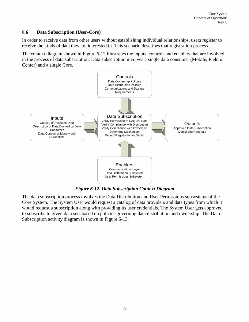
Core System
Concept of Operations
Rev C
72
6.6 Data Subscription (User-Core)
In order to receive data from other users without establishing individual relationships, users register to
receive the kinds of data they are interested in. This scenario describes that registration process.
The context diagram shown in Figure 6-12 illustrates the inputs, controls and enablers that are involved
in the process of data subscription. Data subscription involves a single data consumer (Mobile, Field or
Center) and a single Core.
ControlsData Ownership Policies
Data Distribution Policies
Communications and Storage
Requirements
InputsCatalog of Available Data
Description of Data Desired by Data
Consumer
Data Consumer Identity and
Credentials
EnablersCommunications Layer
Data Distribution Subsystem
User Permissions Subsystem
Data SubscriptionVerify Permission to Request Data
Verify Compliance with Distribution
Verify Compliance with Ownership
Determine Mechanism
Record Registration or Denial
OutputsApproved Data Subscription
Denial and Rationale
Figure 6-12. Data Subscription Context Diagram
The data subscription process involves the Data Distribution and User Permissions subsystems of the
Core System. The System User would request a catalog of data providers and data types from which it
would request a subscription along with providing its user credentials. The System User gets approved
to subscribe to given data sets based on policies governing data distribution and ownership. The Data
Subscription activity diagram is shown in Figure 6-13.
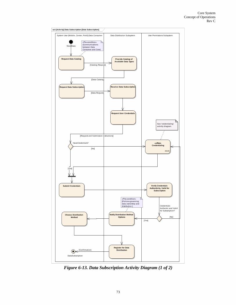
Core System
Concept of Operations
Rev C
73
act [Activ ity] Data Subscription [Data Subscription]
System User (Mobile, Center, Field):Data Consumer Data Distribution Subsystem User Permissions Subsystem
NeedData
Request Data Subscription Receiv e Data Subscription
Request User Credentials
HaveCredentials?
Submit Credentials
«effbd»
Credentialing
Verify Credentials
Authenticity, Valid for
Subscription
Credentials
Authentic and Valid
for Subscription?
Notify Distribution Method
Options
Choose Distribution
Method
Register for Data
Distribution
DataSubscription
«Pre-condition»
{Policies governing
data ownership and
distribution.}
«Pre-condition»
{Communications
between Data
Consumer and Core}
Request Data Catalog Prov ide Catalog of
Av ailable Data Types
See 'credentialing'
activity diagram.
[Yes]
[Data Request]
[Request and Submission Instructions]
[No]
[Yes]
[No]
[Confirmation]
[Catalog Request]
[Data Catalog]
Figure 6-13. Data Subscription Activity Diagram (1 of 2)

Core System
Concept of Operations
Rev C
74
During the subscription process, it is possible that the User Permissions subsystem will engage the data
consumer in a dialog regarding credentialing and permission to subscribe to data. In this case, Core Op-
erations Personnel may be involved, as illustrated in the Credentialing Activity (Figure 6-14).
act [Activ ity] Credentialing [Credentialling]
System User:Data Consumer User Permissions Subsystem Core Personnel:Administrator
UnCredentialedUser
«Pre-condition»
{Notified of user without credentials sufficient
for the activity the user wishes to engage in.
Have address and communications path to
user.}
Prov ide Credential
QuestionnaireProv ide Credential
Questionnaire Responses
Compare Responses
against Policies relev ant
to Credentials requested
Core Personnel
Input Required?
Process Request
Approved?
Accepted?
Notify of Rationale for
Rejection
Credentials
Not Granted
Grant Credentials
Credentials
Granted
[No]
[Yes][No]
[Yes]
[No]
[Yes]
[Questionnaire]
Figure 6-14. Data Subscription Activity Diagram: Credentialing (2 of 2)

Core System
Concept of Operations
Rev C
75
6.7 Data Registration (User-Core)
Based on data ownership and distribution policies, the Data Registration service allows Data Providers
to register their data with the Core System so other users can discover and access their data.
The context diagram (Figure 6-15) shows that the Core System will accept the data‘s metadata as well as
the data provider‘s identity and credentials. The Core is responsible for determining if the data is accept-
able based on system policies and validates the data provider and data if they meet all of the acceptance
criteria. Subsequently, the Core adds to its catalog of data providers and data types.
ControlsData Ownership Policies
Data Distribution Policies
Communications and Storage
Requirements
Inputs
Description of Data to be Provided
Data Provider Identity and Credentials
EnablersCommunications Layer
Data Distribution Subsystem
User Permissions Subsystem
Core2Core Subsystem
Data RegistrationVerify DataType is Desired
Verify Data Provider Not Bad Actor
Provide Distribution Mechanism
Register Provider
OutputsData Provider Mechanism for
Providing Data
Provider Registered
Figure 6-15. Data Registration Context Diagram
The Data Registration activity diagram (Figure 6-16), starts with a prospective Data provider indicating
that it wants to provide data. The Data Distribution subsystem screens the data based on the data collec-
tion policy. If the data registration request isn‘t handled by the initially contacted Core, it may forward
the request to another Core. If the data registration request could be handled by the initial Core, the Core
examines the type of data registered; from here there are two possibilities:
1. If this data is of a type that the Core accepts from anonymous sources, it then determines where
this data should be sent (either an external sink or the Core‘s publish-subscribe engine) and for-
wards the appropriate network address to the System User.
2. If this data is not of a type that the Core accepts from anonymous sources then it examines the
identity credentials of the registering System User; if that user is permitted to provide the data
types it is registering to provide, then the Core determines where this data should be sent, either an
external sink or the Core‘s publish-subscribe engine, and forwards the appropriate network address

Core System
Concept of Operations
Rev C
76
to the System User. If the user is not permitted to provide this data, the Core responds with a mes-
sage indicating the System User is not permitted to provide that data.

Core System
Concept of Operations
Rev C
77
act [Activ ity] Data Registration [Data Registration]
System User (Mobile, Field, Center):Data Provider Data Distribution Subsystem User Permissions Subsystem Core2Core Subsystem
InitiateRegistration
Data Provider
has data he
wants to provide.
Inquire about prov iding
DataCompare Data System
User wants to prov ide to
Data Collection Policy
Data Collection Policy
defines what data is
distributed through this
Core, and what data is
distributed by other
Cores that have
overlapping coverage.
Data handled by this Core?
Compare Data and System
User Identity against Data
Origination Policy
Data Origination Policy
defines for each data
type whether there are
any quality, provider
identity or other
requirements
associated with data to
be provided to this
Core.Identity required?
Request User Credentials
(from Data Subscription)
HaveCredentials?
Submit Credentials
(from Data Subscription)
«effbd»
Credentialing
(from Data Subscription)
See 'credentialing'
activity diagram.
Verify Credentials
Authenticity, Valid for
Registration
Credentials Authenticated and
Valid for Registration
Send Inquiry to Remote
Core that Manages this
Data Type
Data Managed by Other Core?
Prov ide Distribution
Mechanism Information to
System User
No
Registration
At this point the flow of
control leaves this
Core, and is managed
by the referring Core.
Succeeding steps as
shown below would be
carried out by the other
Core that did want the
data in question.
Request
Passed to
Other Core
Record Registration
This will include at
least "1 user registered
to provide <data>". It
could include identity
if identity is required.
Registration
complete
Core-side
Record Distribution
Mechanism
Registration
Complete
System
User-side
«Pre-condition»
{Data Provider has
communications with
Core}
[Yes]
[No]
[Request and Submission Instructions]
[No]
[No]
[No]
[Yes]
[Yes]
[Data Not Used] [Yes]
[Yes]
Figure 6-16. Data Registration Activity Diagram

Core System
Concept of Operations
Rev C
78
6.8 Remote Services (User-Core-Core)
There are several circumstances that may require Cores to cooperate.
1. Cores with overlapping geographic coverage will have to cooperate with regard to data distribu-
tion.
2. All Cores must share CRLs (see Section 6.3)
3. Cores can work together to proxy services, so even if one Core does not provide a given service it
can ―reach back‖ to another to provide that service. This supports Mobile System Users that move
from Core to Core and expect or require a service provided by a remote Core.
4. Provision of services from a Core to a Mobile System User that it does not have direct communica-
tions with. In this case one Core is acting as service router between the Mobile System User and a
Core.
5. Core-to-Core synchronization of data provider and data type catalogs (see Section 6.12)
Figure 6-17 summarizes the remote services scenario for a case where the System User wants a service
not offered by the Data Distribution subsystem in the Core it contacts.
ControlsCore2Core Cross-Provider Policies
InputsRequest Service from Core that is not
provided
EnablersCommunications Layer
Core2Core Subsystems
(Data Distribution) or other applicable
Subsystems
Remote ServicesForward Service Request to remote
Core
OutputsService Request routed to remote
Core
Figure 6-17. Core System Operation Context Diagram
The Remote Services activity diagram (Figure 6-18) depicts how the appropriate Core is determined
based on the service requested by the System User. The Core(s) would need to be communicating with
each other as a precondition. It is also required that the System User can access the appropriate Core.
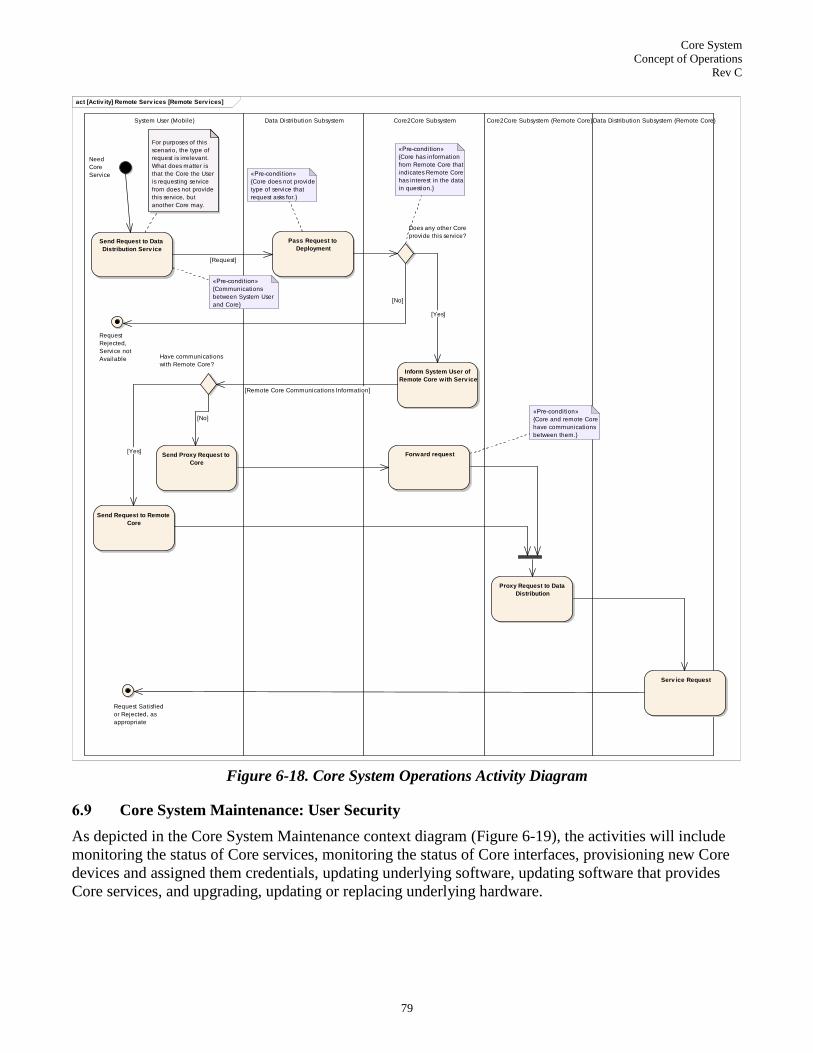
Core System
Concept of Operations
Rev C
79
act [Activ ity] Remote Serv ices [Remote Serv ices]
System User (Mobile) Data Distribution Subsystem Core2Core Subsystem Core2Core Subsystem (Remote Core)Data Distribution Subsystem (Remote Core)
Need
Core
Service
Send Request to Data
Distribution Serv ice
For purposes of this
scenario, the type of
request is irrelevant.
What does matter is
that the Core the User
is requesting service
from does not provide
this service, but
another Core may.
Pass Request to
Deployment
«Pre-condition»
{Core does not provide
type of service that
request asks for.}
Forward request
Does any other Core
provide this service?
Inform System User of
Remote Core with Serv ice
Send Proxy Request to
Core
Have communications
with Remote Core?
Send Request to Remote
Core
Proxy Request to Data
Distribution
Request Satisfied
or Rejected, as
appropriate
«Pre-condition»
{Core has information
from Remote Core that
indicates Remote Core
has interest in the data
in question.}
Request
Rejected,
Service not
Available
«Pre-condition»
{Communications
between System User
and Core}
Serv ice Request
«Pre-condition»
{Core and remote Core
have communications
between them.}
[Yes]
[Request]
[No]
[Remote Core Communications Information]
[Yes]
[No]
Figure 6-18. Core System Operations Activity Diagram
6.9 Core System Maintenance: User Security
As depicted in the Core System Maintenance context diagram (Figure 6-19), the activities will include
monitoring the status of Core services, monitoring the status of Core interfaces, provisioning new Core
devices and assigned them credentials, updating underlying software, updating software that provides
Core services, and upgrading, updating or replacing underlying hardware.

Core System
Concept of Operations
Rev C
80
ControlsOperational Policies
Available Personnel
Minimum Performance Requirements
InputsMaintenance Needs
Underlying Software Updates
Service Software Updates
System User Service Request
EnablersMaintenance Procedures
User Security Subsystem
Service Monitor Subsystem
Core Sys MaintenanceMonitor Status of Core Services
Monitor Status of Core Interfaces
Update Underlying Software
Update Service Software
Replace Supporting Hardware
OutputsUpdated Underlying Software
Updated Services Software
Updated Supporting Hardware
Delayed Service Request
Figure 6-19. Core System Maintenance Context Diagram
This Core System Maintenance scenario describes the effects of Core Personnel updating a single ser-
vice, in this case User Security, and the effects this has on System Users. It is possible that when a ser-
vice is placed in a non-operational state for maintenance that no Users attempt to access it prior to the
service returning to operations. This scenario posits a hypothetical System User attempting to renew cer-
tificates, and the repercussions of maintenance activities on their operation. The Core System Mainten-
ance activity diagram is depicted in Figure 6-20.

Core System
Concept of Operations
Rev C
81
act [Activ ity] System Maintenance [System Maintenance]
Core System Personnel User Security Subsystem System User
Example«stream»
Initiate
Maintenance
Activity on
User Security
Subsystem
Enter Maintenance State
Request Certificate Update
from Core
(from UpdateCertificateActivity)
Store Certificate Request
Notify of Delayed
Response
Distribute Certificate
Request Information and
other activ ities of
Certificate Update
Perform Maintenance
Activ ity
Return to Operational
State
Delayed
Maintenance
Activity
Complete
«Pre-condition»
{Core Personnel
permitted to perform
maintenance on User
Security Subsystem}
Instruct User Security
Subsystem to Enter
Maintenance State
This section reflects
what happens when a
request for service
comes in while already
in the maintenance
state.
[control]
[Stored Certificate Request]
[Certificate
Request
Information]
Figure 6-20. Core System Maintenance Activity Diagram (1 of 2)
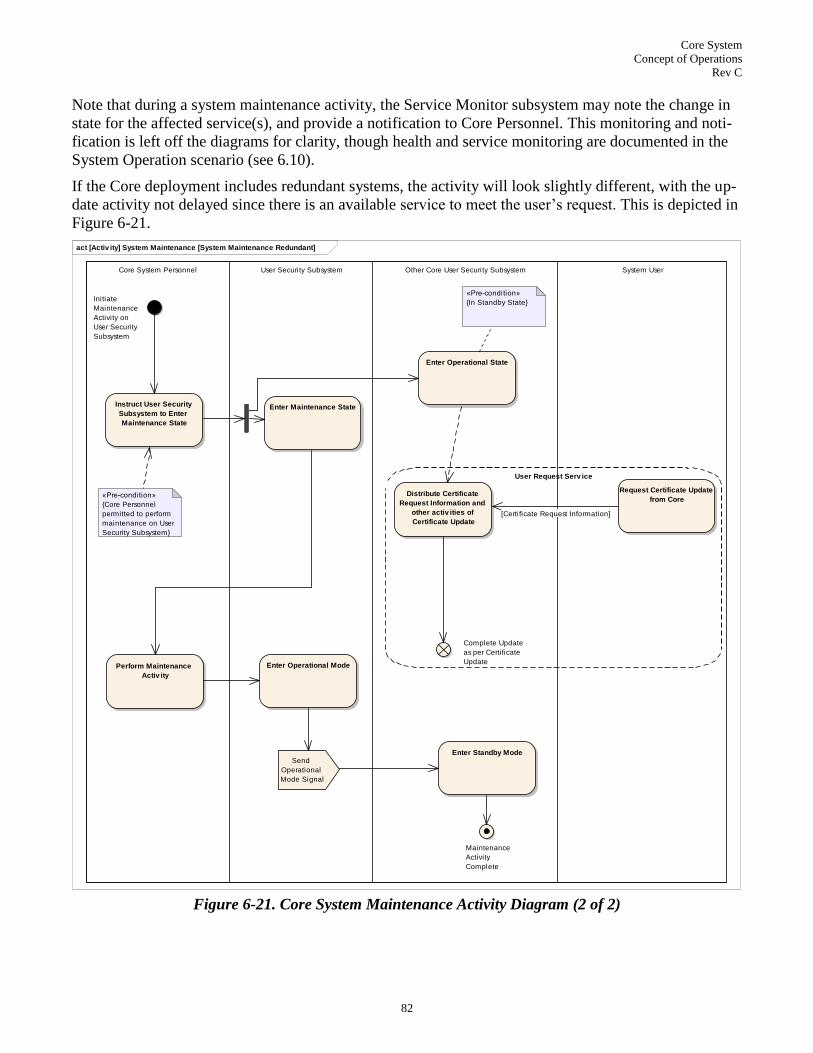
Core System
Concept of Operations
Rev C
82
Note that during a system maintenance activity, the Service Monitor subsystem may note the change in
state for the affected service(s), and provide a notification to Core Personnel. This monitoring and noti-
fication is left off the diagrams for clarity, though health and service monitoring are documented in the
System Operation scenario (see 6.10).
If the Core deployment includes redundant systems, the activity will look slightly different, with the up-
date activity not delayed since there is an available service to meet the user‘s request. This is depicted in
Figure 6-21.
act [Activ ity] System Maintenance [System Maintenance Redundant]
Core System Personnel User Security Subsystem Other Core User Security Subsystem System User
User Request Serv ice
Initiate
Maintenance
Activity on
User Security
Subsystem
Enter Maintenance State
Request Certificate Update
from CoreDistribute Certificate
Request Information and
other activ ities of
Certificate Update
Perform Maintenance
Activ ity
Enter Operational Mode
Maintenance
Activity
Complete
«Pre-condition»
{Core Personnel
permitted to perform
maintenance on User
Security Subsystem}
Complete Update
as per Certificate
Update
Enter Operational State
Send
Operational
Mode Signal
«Pre-condition»
{In Standby State}
Enter Standby Mode
Instruct User Security
Subsystem to Enter
Maintenance State
[Certificate Request Information]
Figure 6-21. Core System Maintenance Activity Diagram (2 of 2)

Core System
Concept of Operations
Rev C
83
6.10 Core System Operations
Core System Operations describes the day-to-day ―housekeeping‖ activities that the Core System and
Core Personnel are engaged with the aim of monitoring and maintaining operation of Core System ser-
vices. The efforts involved will vary depending on several factors:
1. As noted in Section 5.0, Core System scope is highly variable. Generally speaking, the more ser-
vices a Core offers, the more Core System Personnel will have greater operational responsibilities.
2. Cores operating under policies that do not require much (or any) intervention from a human deci-
sion maker in order to function will naturally require less Core Personnel than one that does require
more human interaction.
The Core System Operations context diagram is shown in Figure 6-22.
ControlsOperational Policies
Available Personnel
InputsOperational Performance Measures
Performance Thresholds
EnablersService Monitor Subsystem
Operational Procedures
Core Sys OperationsMonitor Status of Core Services
Monitor Status of Core Interfaces
Identify Services and Interfaces
approaching capacity thresholds
OutputsCore System Status Metrics
Suggested Service Modifications
Figure 6-22. Core System Operations Context Diagram
Core System Personnel activities will be governed by a set of operational procedures which should be
defined prior to beginning operations. For the purposes of developing an understanding of the scope of
these responsibilities, the following activity flows (Figure 6-23) document the types of activities person-
nel may have to engage in, but not the procedures themselves.

Core System
Concept of Operations
Rev C
84
act [Activ ity] System Operation [System Operation]
Core System Personnel:Administrator Service Monitor Subsystem
Continuous Monitor«iterative»
Verify Core Serv ice
Authenticity (all serv ices)
Check for Supporting
Software Updates
Scan for Vulnerabilities
Monitor Physical Alarms
Verify Core Serv ices
Operational State (all
serv ices)
Monitor Env ironmental
Conditions
Monitor Power Systems
Verify Communications
Interfaces
Calculate Serv ice
Performance Metrics
View System Health,
Follow Exception Handling
Procedures
Authenticity
Exception
Handle Exception: Issue
Alarm, Shut Down
Serv ice, Start Authentic
Serv ice
Authenticity
Exception
Vulnerabil ity
Exception
Vulnerability Exception:
Issue Alarm, Secure
Vulnerability, Shut Down
Serv ices
Vulnerabil ity
Exception
UpdateException
SoftwareUpdateException:
Install Patches, Restart
Serv ices
UpdateException
Communications
Interface
Exception
Communications Interface
Exception: Issue Alarm,
Recov er Interface
Communications
Interface
Exception
Service
Exception
Serv ice Exception:
Restart
Service
Exception Physical Alarm
Exception
Physical Alarm Exception:
Broadcast Alarms, Lock
System, Shutdown
Physical Alarm
Exception
Environmental
Exception
Env ironmental Condition
Exception: Engage
Backup Systems,
Shutdown
Environmental
Exception
Service
Performance
Metrics
Exception
Performance Metrics
Exception: Thresholds
Reached: Increase
Capacity, Issue Alarms
Service
Performance
Metrics
Exception
Power
System
Exception
Power System Exception:
Engage Backup Systems,
Issue Alarms
Power
System
Exception
Relevant procedures
wil l include performing
a diagnosis of
subsystem states, and
possibly altering the
state of one or more
subsystems. This could
result in notification of
state change to other
Cores, or bringing
Standby Core services
to operational state.
Begin
Operations
End
Operations
[Software Update Status]
[Vulnerabil ity Status]
Vulnerabil ity Exception
«flow»
[Service Authenticity Status]
[Core Service Status]
[Physical Alarm Status]
Service Performance Metrics Exception«flow»
Environmental Conditions Exception «flow»
[Power System Status]
[Environmental Conditions Status]
Software Update Exception
«flow»
Power System Exception«flow»
Service State Exception
«flow»
Authenticity Exception
«flow»
[Service Performance Metrics]
Communications Interface Exception«flow»
[Communications Interface Status]
Physical Alarm Exception
«flow»
Figure 6-23. Core System Operations Activity Diagram

Core System
Concept of Operations
Rev C
85
6.11 System Expansion
System expansion refers to two possible types of expansion: addition of additional capacity to provide
increased service support, and addition of new services. The following context diagram (Figure 6-24)
serves for both.
ControlsAvailable Resources
Available Personnel
Data and Service Policies
InputsNew Services Needed
Expanded Services Needed
EnablersExpansion Procedures
System User Expansion Support
(Data Distribution) or other relevant
susbsytem(s)
Core ExpansionAdd Services
Expand Services
OutputsIncreased Service Capacity
Additional Services
Figure 6-24. System Expansion Context Diagram
This scenario depicted in the activity diagram presented in (Figure 6-25) concerns what happens when a
given Core is deployed without a service, in this case Data Distribution. Subsequently, the system is ex-
panded to support that s
ervice causing previous ways of communicating data to be less desirable.
The interesting piece of this scenario comes at the end. In this scenario a new Data Forwarding service
where none had previously existed is deployed. Existing direct Data Provider-to-Data Consumer data
provision relationships should be dissolved to take advantage of this new service. Such relationships
could remain intact, but maintaining data provision relationships in an environment where a Core sup-
plied publish-subscribe technology would be inefficient in terms of bandwidth and data provider
processing resources. This implies however that Data Providers and Data Consumers must have a
means for cancelling existing relationships when prompted by the Core, and that they must have a
means for receiving that prompt.

Core System
Concept of Operations
Rev C
86
6.12 Core Discovery
This scenario depicts how a System User discovers a Core System and request services. The System Us-
er queries the communications mechanism for the address of a Core. The Core address can then be used
to query the Core for the status of available services. The context diagram for Core discovery is shown
in Figure 6-26.
act [Activ ity] System Expansion [System Expansion]
Core System Personnel Data Distribution Subsystem System Users
Initial
«Pre-condition»
{Core System does not
include Data
Redistribution as part
of the Data Distribution
service.}
Install Data Redistribution
aspect of Data Distribution
New Functionality
Integrated
Notify Data Prov iders and
Data Consumers of Data
Redistribution
Functionality
Optionally Dissolv e
existing direct data
prov ision relationships
End
New
Functionality
Added
«probability»
Figure 6-25. System Expansion Activity Diagram

Core System
Concept of Operations
Rev C
87
ControlsCore Discovery Policy
InputsStandard Core Name
EnablersService Monitor Subsystem
Communications Layer
Network Services Subsystem
Core2Core Subsystem
Core DiscoveryProvide Core System Address
Provide Status of Core Services
OutputsCore System Address
Information Necessary to address
Core Services at System User
Figure 6-26. Core Discovery Context Diagram
The System User queries the Communications Layer as it enters an area with a standardized Core Sys-
tem domain name. The Communications Layer returns a Core address that has been previously regis-
tered with that name for that area. The Core address is used to communicate with that particular Core to
determine Core service availability. The System User is provided with information on which services
are available and how to access them. The activity diagram for Core discovery is shown in Figure 6-27.

Core System
Concept of Operations
Rev C
88
act [Activ ity] Core Discov ery [Core Discov ery]
System User Communications Layer Service Monitor Subsystem
Start
Query Communications
Layer with Standard Core
Name
Resolv e Standardized
Core Name
«Pre-condition»
{Cores operating in
area have registered
with appropriate
Communications Layer
servers (e.g. DNS) and
coordinated with one
another through
Network Services and
Core2Core subsystems.}
Prov ide Core System
Address
Obtain Core System
Address
Request Core Serv ices Prov ide Status of Core
Serv ices
Received
Information
Necessary to
Access Core
Services
Figure 6-27. Core Discovery Activity Diagram

Core System
Concept of Operations
Rev C
89
7.0 SUMMARY OF IMPACTS
Implementation of the Core System will support the vision of enabling transformative change within the
transportation environment. The Core System facilitates interactions between Mobile, Field and Center-
based entities; this forms the foundation for communication-based applications. The subsections below
identify potential operational impacts, organizational impacts, and impacts during development as well
as ways of measuring these impacts.
7.1 Operational Impacts
This section describes the impacts that the Core System will have on the entities (public agencies or pri-
vate firms) that operate the system as well as the users that use the technologies and applications that
will be deployed in the connected vehicle environment. Operational impacts of the Core System will in-
clude capabilities that are beneficial to users, developers, operations and maintenance personnel.
The most significant operational impact of the Core System will be enabling new applications that pro-
vide benefits to travelers and the transportation system to improve safety, traveler's mobility, and reduc-
ing transportation's impact on the environment. Expected benefits include21
:
Reductions in numbers of accidents, accident severity and a corresponding drop in transporta-
tion-related fatalities. Insurance costs should decrease accordingly.
Reductions in congestion, delay and related time lost commuting; increased use of public trans-
portation and increased multi-modal coordination.
Reductions in transportation-related greenhouse gas emissions.
Data collection enabled by the Core System will also enhance existing transportation applica-
tions. Two commonly cited examples from the user needs workshops are that traffic mobility ap-
plications will benefit from new sources of traffic data and weather applications will benefit from
new sources of weather data.
Deployment of the Core System will open up access to applications over different communication
access mechanisms such as 3G/4G cellular, thus fusing new communications media with what had pre-
viously been closed communications networks. This allows agencies operating transportation infrastruc-
ture the opportunity to reduce their reliance on or commitment to maintaining their own communications
infrastructure. Today, the traveling public accesses traveler information via the internet, telephone,
DMS, or the radio – all of which are limited somewhat by the deploying agency's installation coverage
and policies and procedures governing those outlets. Future applications will provide more ways to re-
ceive useful, timely information.
Procuring network access at the Core System and by/for System Users will have a long term fiscal im-
pact. Cores that operate publish and subscribe services may have to absorb significant bandwidth costs.
System Users relying on cellular communications will have to pay for those links. Centers that pull large
amounts of data may also see significant communications costs. Field users may as well, though the va-
riety of access methods, including traditional terrestrial land lines and private networks that may already
exist to support other ITS may ameliorate some of these costs.
21
The Core System does not itself provide these benefits, it provides the foundation that applications can leverage to provide
these benefits. Development, testing and deployment of these applications is part of the critical path toward realizing benefits.

Core System
Concept of Operations
Rev C
90
The primary impacts to operators and maintenance staff of the Core System are the new hardware and
software that will be deployed to perform the functions listed in Sections 4.0 and 5.0. The hardware will
include workstations, servers, routers, firewalls etc. that will need to be operated and maintained.
The incorporation of network management tools and diagnostic software tools should simplify the day-
to-day operations of operations and maintenance personnel. Regardless of how difficult the Core and
various communications systems are to manage however, those personnel will still have more responsi-
bilities than they do today, simply by having to operate the Core System.
Operators and maintenance staff will also be impacted by changes to operational procedures. Current
operational procedures are primarily focused on roadside device management whereas this program will
provide the ability to focus on communications directly to the vehicle. This allows for more dissemina-
tion locations, with more flexibility and potentially more content to be communicated to travelers. For
example, a DMS currently is at a fixed location so only drivers within sight of the sign will receive the
message displayed on the sign. With this program, the ability to send messages similar to what is cur-
rently displayed on a DMS to in-vehicle systems will be possible.
The deployment of the Core System will facilitate the collection of new data from new sources, chiefly
vehicle-based, that can be used by transportation planners and other staff to improve long range plan-
ning. This should improve visibility into traffic patterns, usage of transit facilities, and relationship and
trend analysis, such as between traffic and weather conditions. Enhanced data collection should also fa-
cilitate new ways of monitoring and managing traffic that help in improving operations. Data retention
requirements should also be considered.
Testing and deployment of the Core System will have an impact on the Operations staff that may al-
ready be operating a transportation system; the Core System will need to operate in parallel. Integration
issues between legacy systems and Cores could hinder Core deployment. For example, a traveler infor-
mation system may be based on a legacy database. In order to take advantage of data from data provid-
ers of this program the operators of that traveler information system may need to develop special inter-
faces.
Security and privacy requirements will introduce a new set of policy and institutional issues that need to
be addressed. For instance, the security requirements of technologies such as 3G/4G cellular need to be
evaluated and understood when these communication mechanisms are used. The services of the Core
System open the possibility for application developers to take advantage of the centralized security me-
chanisms of the Core to supplant their current independent approaches to security – they can let the Core
take care of security and concentrate on their application needs.
It will be necessary to deploy system and technological refreshes on a continuous basis to keep the Core
System up-to-date. It will be necessary to patch software and upgrade hardware on a regular basis. Pro-
cedures and mechanisms for these updates will have to be developed and agreed to by Core System op-
erators. The subsystems described in Section 5.0 such as Service Monitor will allow the system to be
maintained and kept up-to-date. Over time, deployment and use of connected vehicle technologies will
supplant existing devices/systems and reduce the maintenance required for those legacy systems.
The Core System support for wireless systems will provide bandwidth for larger data set exchanges than
what is possible with DSRC alone. Even travelers that do not interact with the Core or System Users
will benefit through improved traffic control, improved transit operational efficiencies, better response
time for incidents, etc.

Core System
Concept of Operations
Rev C
91
Device manufacturer support for the connected vehicle environment will enable a variety of new opera-
tional procedures that should improve remote diagnosis of vehicle and device problems. This could re-
sult in a closer relationship between manufacturers and vehicle/device owners, particularly if software
refresh of OBE is regularly required. At least in the early phases of deployment, as services are rolled
out and operations refined, this seems likely.
Additional operational impacts may include the following items:
Changes in operational risks – integrating with public system networks may increase opportunities
for Core Systems to be exposed to hacking or other intrusions. On the other hand, more detailed
and geographically comprehensive information about the road conditions are available using this
program which will lead to better management of the transportation network.
Advances in technology – faster processing, different communications mechanisms available, and
other aspects like the use of IPv6 may impact how the Core System is deployed and may require
additional training for personnel using and maintaining the system.
7.2 Organizational Impacts
This section addresses the impacts the new system will have on deployers and operators of the Core Sys-
tem. Public agencies or private entities that will plan for, manage, operate and maintain a Core will es-
tablish roles and responsibilities that are different than what exists at present. New roles may need to be
created in certain areas like coordinating with public and private network operators, security certificate
authorities etc. while responsibilities of some of the existing personnel involved with planning, manag-
ing, operating and maintaining will be modified to align with the Core System needs.
Based on the changes in work load, there may be a requirement to hire or retrain additional personnel
subject to budgetary considerations. For example, deployment of the Core System will provide a variety
of new data that can be used to improve operations. However, if this results in increased workload, hir-
ing of extra staff may need to be evaluated. Early on, the existing staff will likely be tasked with addi-
tional duties to operate and maintain the new system.
The organizational impacts will vary depending on the deployment approach chosen. While no policy
decisions have yet been made with regard to how Core Systems may be deployed, there are some im-
pacts that can be identified. A Core deployer may contract out the entire system, some parts of it, or may
decide to build and manage the system using their own agency resources. In some cases, the same or-
ganizations that manage and operate ITS today will be deploying and managing this next generation sys-
tem. In other cases, there will be new organizational structures established. The services deployed and
the sequence in which these services are deployed may also have organizational impacts (for example,
initial deployments might be limited in scope, such as a deployment focused on support for commercial
vehicle fleet operations).
The organization needs to plan, manage, operate and maintain the subsystems of the Core System identi-
fied in Section 5.0. Personnel assigned to Core System positions will be required to meet the minimum
skill requirements that will be identified. This will vary based on the types of services implemented and
applications supported by a Core. For example, some operators will need to be able to monitor and
maintain system security credentials. Other operators may need to be able to manage databases and how
system users access system resources. Training needs to be provided to existing personnel to enhance
their skill level to meet these minimum skill requirements. For positions where this is not possible, re-
cruitment from outside the organization should be considered.

Core System
Concept of Operations
Rev C
92
Training should include classroom training and hands-on training on each of the subsystems as well as
operations and maintenance crew training. Classroom training provides the student with the concept of
operations, relationships, individual product features, and an introduction to the hardware and software
interfaces. Hands-on training allows the student to work with hardware components and software appli-
cations to view/change product configurations and practice basic operator and maintainer tasks.
Crew training provides the operators the necessary skills to operate their portion of the system in con-
junction with other operators external to the Core System. The goal of crew training is to achieve a re-
quired level of proficiency for each Core System position by conducting challenging scripted scenarios
that replicate typical operations in the Core.
In addition, personnel should be provided training on courses when it is expected that they need to be
certified to operate and maintain certain types of equipment, software, or network services.
Deployment of the Core System subsystems will occur across multiple agencies (both public and pri-
vate) with interdependent, and in some cases, overlapping areas of responsibilities. These interactions
with other agencies, both government and private, will require institutional agreements in order for the
Core to work. These institutional agreements will help identify the boundaries for the responsibilities of
personnel across Cores, certificate authorities, government organizations, legal authorities, private net-
work operators and public network operators, etc. Arrangements should also be considered for providing
contingency operations at one or more sites following an emergency, natural disaster, or other accidents.
Manufacturers of vehicles equipped to participate in the connected vehicle environment may also re-
quire requisite organizational bodies to implement and manage the applications they use to monitor and
maintain vehicles they support.
7.3 Impacts during Development
This section addresses the impacts that the Core System will experience while the system is being de-
veloped or expanded. During the development phases, there will likely be a need for continuous analy-
sis, research and planning. Demonstrations and test activities will need to be conducted using facilities
such as the Detroit test-bed. New and enhanced capabilities will need to be tested, verified and vali-
dated. Performance measurements, both qualitative and quantitative, will need to be collected during the
early testing. Continuous analysis, research and planning will be required in the areas of security and
scalability etc. The activities may include modeling of these features to better understand the impacts.
Demonstrations and test activities should be conducted whenever development of a significant feature
set is complete. Parallel operations will be conducted, wherever possible, with existing systems continu-
ing to operate while the Core System is installed and tested. As the Cores are established and new fea-
tures are added or technology is refreshed, similar demonstrations and test activities should still be con-
ducted.
Additional impacts may include the following:
Development of rules and controls needed for operational implementation.
System documentation updates.
Involvement in studies, meetings, and discussions prior to design and programming.
Involvement in reviews and demonstrations, evaluation of revised operating capabilities, develop-
ment or modification of databases, and required training.
Impact of new interface design and testing

Core System
Concept of Operations
Rev C
93
7.4 Measuring the Impacts
The Core System can provide metrics that are indirectly related to the overall program goals but that
provide indicators of the success of the Core System:
Number and types of applications registered with the Core System
Number and type of data subscribers
Number and type of data providers
Usage of Data Distribution services
Other Core Service metrics like system availability to indicate overall health of the system
Other measures including adoption of connected vehicle applications and their usage (number of appli-
cation hits) will require evaluating data from sources external to the Core System. Other statistics like
new organizations created, jobs created, companies created can also be measured to evaluate the indirect
impacts of deploying a Core. Implementation of the Core will cost money for equipment, network com-
munications, and labor. The impact of these costs should also be measured. Additional analysis will be
needed to determine the costs associated with operations, organizations and development.
To measure the performance of the system or the impact of the deployment of Core System will require
measuring and comparing pre-defined parameters with current values. The necessary baseline measure-
ments will vary by region and by the services being deployed.
Performance measurement should be part of the continuing operation of any automated system like this
program. Agencies or companies deploying a Core System will establish the metrics they consider im-
portant for their operation and continually or periodically measure the behavior of the system against
those metrics. Variations from the baseline metrics will be reviewed for potential problems with dep-
loyed systems or identifying changes or upgrades needed over time.
Misbehaving entities will have a negative impact on the adoption and success of this program. Misbeha-
vior detection mechanisms are incorporated into the Core System, but policies for action based on mis-
behavior are left to the Core operator to determine, based on local policies and agreements with other
Cores. Parameters should be identified for certifying and decertifying operating entities associated with
Core Systems. These parameters include items related to service like number of user complaints, time
taken to service a complaint, number of outages, downtime etc.
Availability of the Core System is paramount for gaining acceptance with users of this program. Impacts
of the Core System being unavailable or operating in degraded mode need to be measured and all efforts
should be made to ensure that user acceptance is not affected.

Core System
Concept of Operations
Rev C
94
8.0 ANALYSIS OF THE PROPOSED SYSTEM
Various improvements, disadvantages and limitations, and alternatives and trade-offs considered are
covered in this section.
8.1 Summary of Improvements
The Core System will provide new and enhanced capabilities as described in Section 4.0. These new and
enhanced capabilities will offer numerous benefits, some of which are improvements over the current
system.
Trusted Short Range Communication: Interactions between entities in the transportation environ-
ment, when those entities have a reasonable assurance of trust between them, will provide increased sit-
uational awareness for all parties involved. Vehicles, field devices and handhelds can all learn the loca-
tions and even current operating measures such as speed and direction of other vehicles and devices in
their proximity. This short range situational awareness improvement should provide the foundation for
safety and local area mobility applications.
Trusted Long Range Communications: Improved access to entities not in the proximal transportation
environment (chiefly backoffice, but possibly remote field devices) will provide greater ease of access to
mobility and commercial information for vehicles and other transportation users. It will also provide
backoffice users with greater access to data describing the transportation environment, and if anonymous
probe data is widely available, greatly expand the potential base from which those applications can be
sourced.
Increased Communications Options: Support for a variety of communications options for Mobile us-
ers, including DSRC, cellular and Wi-Fi provides flexibility and increased performance over the entire
communications layer. Allowing cellular access to Core services frees up DSRC bandwidth to focus
more on safety applications; while safety was always prioritized above mobility and other applications,
the existence of alternatives could simplify operations for radios that do not have to service non-safety
demands. Further, by providing other options there is greater likelihood that non-safety applications will
have access to the communications resources they require in order to provide benefits.
Infrastructure-light Deployments: By refocusing the Core System as a provider of services and re-
moving its responsibility for operating and maintaining a communications network, it has become possi-
ble to deploy Core services without an extensive network of RSEs. This enables deployments of Cores
independent of the time or other resources required to establish significant field infrastructure, allowing
some operational benefits in a shorter time. For example, a Core could be deployed to distribute certifi-
cates22
, thereby facilitating trust and enabling V2V safety applications between equipped vehicles.
Meanwhile, deployment of RSEs with V2I safety applications at key intersections can proceed at its own
pace, without being constrained by the need to provide all services in the connected vehicle environ-
ment.
Publish-Subscribe Data Distribution: Publish-subscribe offers deployers an efficient way to distribute
data that could not be easily done otherwise. Including this functionality in the Core ensures that it is
constrained by the relevant privacy policies, and may provide users more faith that their data are being
22
There is still some question as to how effective non-DSRC communications will be in distributing large numbers of certifi-
cates. The certificate management scheme has not yet been architected, but the usefulness of cellular, particularly 3G com-
munications, for the renewal of large numbers of certificates is a topic for further study.

Core System
Concept of Operations
Rev C
95
handled in a way they are comfortable with. Further, broadening publish-subscribe beyond probe data
offers application developers more options with regard to reaching their end users.
Open Standards: Open standards offer the promise of high reliability with a technology refresh advan-
tage. This also provides an open market place for application development and integration, which should
yield a rich, broad suite of applications from a variety of providers.
Scalable, Deployable Certificate Management: Certificate management is the basis for establishing
and maintaining trust and enabling encrypted data exchange. Viewing the Core System as a set of ser-
vices that can be implemented independent of a specific box of hardware provides the foundation for a
scalable system design. Architectural design will have to pass the scalability test, but by considering sca-
lability and certificate distribution issues now the foundation has been laid for a deployable, scalable
certificate management system.
Physical Environment Mitigation: The ability to maintain systems, delivering high-availability servic-
es is crucial to the user‘s perception of system utility. If a system is not available when a user needs it,
from his perspective it doesn‘t work. The Core System includes availability monitoring, interface status
and performance monitoring and mechanisms for users to determine which services are available and
where. While the POC implementation of VII included some of this from the operator‘s perspective,
these concepts were not clearly described in the NSR, and in no case did they include the type of user
feedback envisioned here.
System Deployment Options: The Core System is conceived such that it can be deployed independent-
ly within a single jurisdiction, or widely on a large scale, depending on the needs and desires of the enti-
ty deploying the system. This allows each entity and jurisdiction to make their own decisions about
when, where and how extensively to offer Core services. It keeps the Core small enough that it could be
implemented by a wide variety of capable enterprises, not dependent on large scale organizations. This
concept is also consistent with traditional transportation funding and operations policies. While the Core
may not be deployed by a transportation entity, they are one likely candidate for doing so and by allow-
ing the scope and services of the Core to vary, that option is preserved.
8.2 Disadvantages and Limitations
Research programs are ongoing to mitigate risks of the underlying technologies of this program which
should also help identify any limitations in the Core System and the sum of Core Systems; i.e., how
Cores interact and provide services. The concept of a federated system of systems which allows deploy-
ers and operators flexibility could potentially result in multiple, disjointed systems that are difficult to
link together. The interoperability and interdependence needs incorporated in this document attempt to
address this, but it is still possible that the collective task of managing these many systems could become
difficult.
The deployment of this program will likely be regional and evolutionary. This is more practical than one
large deployment when considering capital and other resources required, but will result in slower reali-
zation of benefits than if one large system were quickly deployed. As more and more mobile devices
become enabled, and as field devices and centers become integrated into the system, more benefits will
be realized.
Deploying the Core System across the entire country is by no means a turnkey operation. This is because
the Core System is not a one-size fits all localities kind of system. The Core System will have to be re-
fined for each locality to meet the specific needs of that locality. Also, it will be necessary to address
what to do with existing, legacy systems. It will take a long time for Core deployments to integrate with

Core System
Concept of Operations
Rev C
96
or even supplant traditional ITS. The challenge will be to integrate these different Cores to work togeth-
er within the context of standards, policy, budget, and institutional constraints.
Design, development and deployment of the Core System will involve additional cost to procure the
hardware and software, train personnel etc. This program will have to compete for funding with other
projects like traditional road construction or bridge repairs and upkeep.
The Core System will need to be flexible to accommodate what may seem to be opposing policy issues
such as maintaining user privacy while ensuring security of the system.
Applications should be designed in such a way so they are not dependent on continuous communications
with the Core System. While the Core System concept leverages existing communications to provide
large coverage areas from the moment a Core is deployed, the availability and performance characteris-
tics of these communications technologies vary, and are all outside the direct control of the Core.
The Core System will need to monitor the performance of the communications networks. For example,
the Core will need to detect if DSRC channels become congested during a disaster or other emergency
situation and provide information to system users to potentially reroute communications or to switch to a
degraded mode in an emergency condition without breaking system services. Internal to the communica-
tions provisions based on DSRC, it may be necessary to support multiple channel radios to accommo-
date channel congestion.
System Users that connect to the Core System through cellular technologies will pay for that access in
the form of a monthly fee or contract, while DSRC users will not. If the System User sees a benefit to
paying for a particular type of media access, they will use that service. In areas with significant DSRC
deployments, this may lead to abandonment of cellular technology access, or lead to incentives from cel-
lular providers to use their services.
Personnel will have to be trained on the Core System and new policies and procedures will need to be
developed.
8.3 Alternatives and Trade-offs Considered
Throughout the development of the ConOps, a number of alternatives and trade-offs have been consi-
dered that will affect the definition of the Core System. These include:
Storage of collected transportation related (probe) data within the Core System
Placement of RSEs with respect to the Core System boundary
Scope of services included in the Core System vs. those moved to end user applications
Communications options for deployers
Deployment options
International architectures
Data Storage: Alternatives for data storage within the Core System were considered. It was decided that
the Core itself did not require probe data storage in order for the system to function. Probe data is not
needed within the system. The data is needed for other applications and the Core will provide the servic-
es to ensure that the data can be made available to requesting systems.
RSEs: The Roadside Equipment that includes the radio communications to mobile devices has been
placed outside the Core System boundary and included as part of the Field element. RSEs are the 'first
point of contact' between DSRC-enabled mobile devices and the transportation communications net-
work. If it was included in the Core System any other first points of contact would also have to be in-
Core System
Concept of Operations
Rev C
97
cluded, such as cell towers, and the system would have to define the interface with end users. This al-
lows the Core System to maintain the interface at the application boundary, allowing the applications
maximum flexibility in their user interface design. This also allows for more flexibility in the definition
of the field equipment. Field equipment can be developed to include the DSRC radio along with sensors
or controllers or storage as the developers see fit. For example, medium term storage could be a need for
rural settings where data is aggregated at the RSE over low bandwidth connections. Drawing the RSEs
outside the Core System boundary also eases the transition to allowing for third party or private owner-
ship of RSEs.
Scope of Services: The set of functionality included in the Core System has been limited to just those
that are necessary to enable the connected vehicle environment – ensuring the integrity of the system,
establishing and maintain trust between System Users, distributing data and monitoring Core perfor-
mance. Applications such as collection of data or support for regional standardized clearing houses for
data may be useful considerations for certain types of data or for certain regions.
Communications Options: With the current definition of the Core System, once the data providers are
registered with a Core and the data consumer‘s sets up a subscription for the data, the data can pass be-
tween directly between providers and consumers without involving the Core. This decoupling of the
Core services from the actual communications provides increased access to the data and flexibility to the
deployers of the system. Additionally, the communications networks to support this program could be
set up in various configurations including having their own RSE network, establishing their own Wi-
MAX capability, or they could use existing Municipal Wi-Fi or other available networks.
Deployment Options: With any system development stakeholders should consider what their alterna-
tives are before making any major investments. There are several basic high-level options from which to
choose:
Do Nothing
Develop the system as defined in the ConOps
Let the private sector manage development and deployment
Choose other alternatives
For this program, the Do Nothing option will be selected by those users that decide, for whatever reason,
to continue managing traffic, providing traveler information, managing incidents, providing any trans-
portation service the way they do it today. 'Do Nothing' doesn't mean that the world will be stuck in its
old, as-of-today way of doing things. Instead, there are a number of new technologies that are available
and which are being adopted by automobile vendors, application developers etc. without going down the
route offered by this program. To a large extent, mobility-related aspects could be addressed with the
wide adoption of Smartphones with their plethora of applications
Developing the system as defined in the ConOps (and as to be further defined in the requirements and
architecture definitions) could take place any number of ways, but is generally bound by the answers to
two questions:
1. Who will fund deployment?
2. Who will provide governance over certain parts of the system, such as certificate management or
data access (assuming shared archival data environments)?
Since the answers to these questions are still unclear, the engineering process will continue to include as
much flexibility in the development of the Core System as possible. This will undoubtedly be reflected
Core System
Concept of Operations
Rev C
98
in the architecture, as it will have to accommodate deployments that are built and operated by entities of
widely varying sizes and capabilities.
It is possible that a commercial entity may develop and operate the Core System. Elements of the Core
System could be deployed using web-based services which may make it easier for deployment in a larg-
er number of markets.
A Private Sector development and deployment with a large corporation taking over the design of this
program with no government involvement at all might be possible. A large private Internet or Commu-
nications firm may see the commercial or business advantages of designing their own Core System.
However, open interfaces would still be required in order for individual devices and applications to be
interoperable.
Other options include cases where stakeholders deploy their own communications and applications out-
side of those proposed by this program. The ConOps development process has attempted to include as
wide a group of stakeholders as possible in order to develop a system that is acceptable to as many as
possible. However, if stakeholders choose alternative means of deploying services that is outside the
scope of the Core System, their utility may be limited.
Another alternative for consideration is to rely on autonomous safety systems coupled with whatever the
commercial sector develops in terms of connected vehicle systems. While this program clearly brings
additional benefits, it is likely that it may take a longer time for this program to be deployed when com-
pared to the alternatives considered here.
International Architectures: The Framework Architecture Made for Europe (FRAME) has recently
been updated to include Cooperative ITS systems. ITS services (traffic safety, traffic efficiency, freight
and fleet applications, and value-added services) are all accounted for in the User Needs discussed in
this ConOps. It should be noted however, that the FRAME ITS Service User Needs will continue to in-
form the system engineering effort associated with this program, as much of the material included in the
Cooperative ITS systems update is written at a level akin to what will be the Core System Requirements.
In addition, the Communications, Air-interface, Long and Medium range (CALM) set of standards de-
fines a set of system interactions for the wireless vehicular environment. These too are covered by the
User Needs captured in this ConOps.

Core System
Concept of Operations
Rev C
99
9.0 NOTES
This section contains an alphabetical listing of abbreviations and acronyms used in this document.
Table 9-1. Abbreviation and Acronym List
Abbreviation/
Acronym
Definition
AMS Analysis, Modeling, and Simulation
AASHTO American Association of State Highway and Transportation Officials
AMDS Advisory Message Distribution Service
APTA American Public Transportation Association
ASOS Automated Surface Observing System
AWOS Automated Weather Observing System
BAH Booz Allen Hamilton
CA Certificate Authority
CALM Communications Access for Land Mobile Standards
CAMP Crash Avoidance Metrics Partnership
CCH Control Channel (interval)
CCTV Closed Circuit Television
CICAS Cooperative Intersection Collision Avoidance Systems
cmp Components
COM eSafety Communications for eSafety
ConOps Concept of Operations
COOPERS Cooperative Systems for Intelligent Road Safety
COTS Commercial off-the-shelf
CRL Certification Revocation Lists
CVIS Cooperative Vehicle Infrastructure System
CVO Commercial Vehicles Operation
DCM Data Capture Management
DGPS Differential GPS
DMA Dynamic Mobility Applications
DMS Dynamic Message Signs
DSRC Dedicated Short Range Communication
EC European Commission
EEBL Emergency Electronic Break Light
ENOC Enterprise Network Operations Center
ETSI European Telecommunications Standards Institute
INCOSE International Council on Systems Engineering
FCC Federal Communications Commission
FHWA Federal Highway Administration
FRAME Framework Architecture Made for Europe
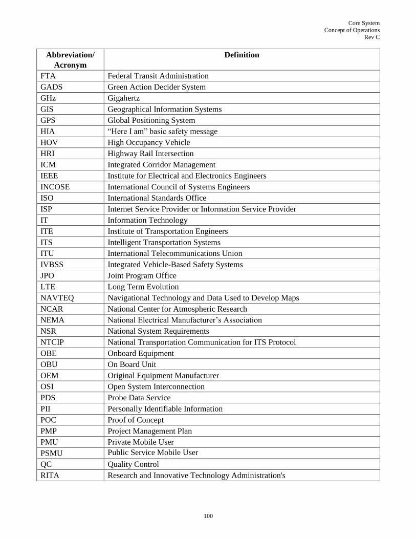
Core System
Concept of Operations
Rev C
100
Abbreviation/
Acronym
Definition
FTA Federal Transit Administration
GADS Green Action Decider System
GHz Gigahertz
GIS Geographical Information Systems
GPS Global Positioning System
HIA ―Here I am‖ basic safety message
HOV High Occupancy Vehicle
HRI Highway Rail Intersection
ICM Integrated Corridor Management
IEEE Institute for Electrical and Electronics Engineers
INCOSE International Council of Systems Engineers
ISO International Standards Office
ISP Internet Service Provider or Information Service Provider
IT Information Technology
ITE Institute of Transportation Engineers
ITS Intelligent Transportation Systems
ITU International Telecommunications Union
IVBSS Integrated Vehicle-Based Safety Systems
JPO Joint Program Office
LTE Long Term Evolution
NAVTEQ Navigational Technology and Data Used to Develop Maps
NCAR National Center for Atmospheric Research
NEMA National Electrical Manufacturer‘s Association
NSR National System Requirements
NTCIP National Transportation Communication for ITS Protocol
OBE Onboard Equipment
OBU On Board Unit
OEM Original Equipment Manufacturer
OSI Open System Interconnection
PDS Probe Data Service
PII Personally Identifiable Information
POC Proof of Concept
PMP Project Management Plan
PMU Private Mobile User
PSMU Public Service Mobile User
QC Quality Control
RITA Research and Innovative Technology Administration's

Core System
Concept of Operations
Rev C
101
Abbreviation/
Acronym
Definition
RSE Roadside Equipment
RSU Roadside Unit
SAE Society of Automobile Engineers
SCH Service Channel (interval)
SDN Service Delivery Node
SE Systems Engineering
SEMP Systems Engineering Management Plan
SPAT Signal Phase and Timing
SRS Software Requirements Specification
stm State Machine
SUV Sport Utility Vehicle
SysRS System Requirements Specification
TC Technical Committee
TMC Transportation Management Center
TRSP Traffic Responsive (Signal Control)
USDOT US Department of Transportation
VDT Vehicle Data Translator
VII Vehicle Infrastructure Integration
VIIC Vehicle Infrastructure Integration Consortium
VMS Variable Message Signal
V2I Vehicle to Infrastructure
V2V Vehicle to Vehicle
WAVE Wireless Access in Vehicular Environments
WiMAX Worldwide Interoperability for Microwave Access

Core System
Concept of Operations
Rev C
102
10.0 APPENDICES
10.1 Workshops
10.2 Vancouver, BC Workshop (10 & 11 August, 2010)
Subject: Vancouver, BC User Needs Findings
Location: Vancouver Convention Center, Room West 113
Date: Tues (8/10/10) and Weds (8/11/10)
SE project Support:
Dawn Hardesty Noblis
Jeris White Noblis
SE project Team:
Kevin Hunter LM
Jeff Brummond Iteris
Tom Lusco Iteris
Alan Clelland Iteris (on phone)
Roger Koehler Iteris (on phone)
Participants:
Last Name First Name Agency Tues Session
(8/10/10)
Wed Session
(8/11/10)
Barbaresso Jim HNTB x x
Beaubien Dick Hubbell, Roth and Clark x x
Boaz Ralph Pillar Consulting x x
Briggs Valerie USDOT/RITA/ITS JPO x x
Bush Mark AASHTO x x
Butin Robert USDOT / RITA x
Cunard Richard TRB x
Deneau Danielle Road Community for Oakland County (on phone) (on phone)
Duncan Gary CTO / Econonlite x x
Engelmann Martin Deputy Executive Director / CCTA x
Garretson Dan Pinyon Labs (on phone) (on phone)
Hayer Jatinder Sr Mgr Epcor Technologies x
Hill Chris Mixon / Hill x
Jacobson Les PB World x
Kance Peter City of Portland Division Mgr x
Leslie Andrew Hewlett Packard (on phone)
McCourt Ranoy DKS Associates x
McKeever Ben USDOT / FHWA x
Miller Dave Siemens x x

Core System
Concept of Operations
Rev C
103
Last Name First Name Agency Tues Session
(8/10/10)
Wed Session
(8/11/10)
Narla Siva ITE
Piotrowicz Gary Road Community for Oakland County x x
Poe Chris TTI x
Rausch Bob VP / TRANSCORE x x
Rossman Dave YCA x x
Rupert Bob FHWA / Team Leader x
Saleem Faisel Maricopa County DOT x x
Schopp Bruce NEMA x x
Seymour Ed Associate Director TTI x x
Sloan Suzanne Volpe x
Tipaldo John VP / TRANSCORE x
Urbanik Tom Kittenban & Associates x
Wolanin Emil Montgomery County DOT x x
Wright Jim AASHTO x x
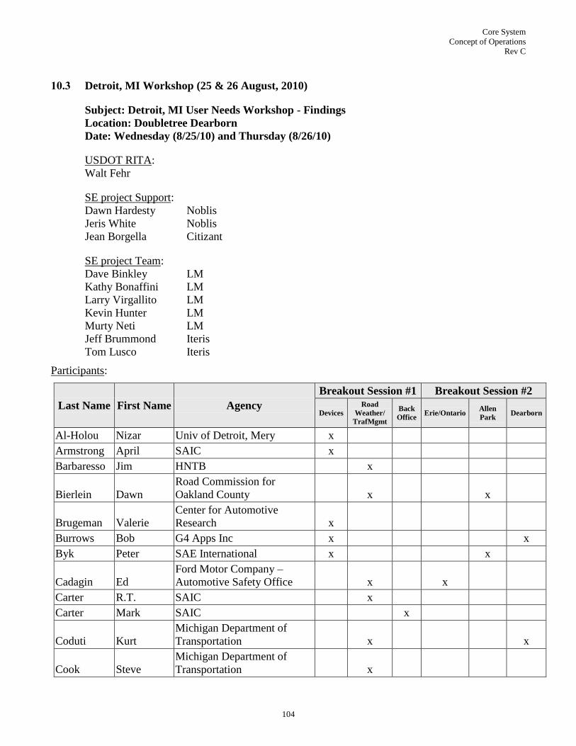
Core System
Concept of Operations
Rev C
104
10.3 Detroit, MI Workshop (25 & 26 August, 2010)
Subject: Detroit, MI User Needs Workshop - Findings
Location: Doubletree Dearborn
Date: Wednesday (8/25/10) and Thursday (8/26/10)
USDOT RITA:
Walt Fehr
SE project Support:
Dawn Hardesty Noblis
Jeris White Noblis
Jean Borgella Citizant
SE project Team:
Dave Binkley LM
Kathy Bonaffini LM
Larry Virgallito LM
Kevin Hunter LM
Murty Neti LM
Jeff Brummond Iteris
Tom Lusco Iteris
Participants:
Last Name First Name Agency
Breakout Session #1 Breakout Session #2
Devices
Road
Weather/
TrafMgmt
Back
Office Erie/Ontario
Allen
Park Dearborn
Al-Holou Nizar Univ of Detroit, Mery x
Armstrong April SAIC x
Barbaresso Jim HNTB
x
Bierlein Dawn
Road Commission for
Oakland County
x
x
Brugeman Valerie
Center for Automotive
Research x
Burrows Bob G4 Apps Inc x
x
Byk Peter SAE International x
x
Cadagin Ed
Ford Motor Company –
Automotive Safety Office
x
x
Carter R.T. SAIC
x
Carter Mark SAIC
x
Coduti Kurt
Michigan Department of
Transportation
x
x
Cook Steve
Michigan Department of
Transportation
x

Core System
Concept of Operations
Rev C
105
Last Name First Name Agency
Breakout Session #1 Breakout Session #2
Devices
Road
Weather/
TrafMgmt
Back
Office Erie/Ontario
Allen
Park Dearborn
Crawford Mark Somat Engineering
x x
Deneau Danielle
Road Commission for
Oakland County
x
DiMambro Tom GM x
x
Dion Francis UMTRI
x
Domin Chris Ricardo Inc x
Duan David Kostal North America x
x
Fahie Michael Booz Allen Hamilton x
x
Fecker Anthony SAIC x
Free Jake Free Enterprises
x
x
Garretson Dan Pinyon
x
Gonzalez Alan Drive NonStop x
Goudy Roy
Nissan Technical Center
North America x
x
Handman Art Independent Consultant
x
x
Hedges Chris Delphi x
x
Hoevel Morrie
FHWA – Michigan Division
Office
Junak Matthew HNTB
x
x
Kelly Kevin MIS
x
Krause Joe TK Holdings x
x
Krechner Dan Cambridge Systems x
Kurihara Thomas TKstds Management
x x
Lahue Craig IBM
x
LeBlanc Dave UMTRI x
Lotoczky Rick Vector Cantech, Inc
x
McCormick Scott
Connected Vehicle Trade
Association
x
McNamara Dave MTS LLC
Mixon Lee Mixon Hill
x
Naboulsi Mouhamad iQ-Telematics x
x
Noblett Mike IBM x
x
Patel Arpan Somat Engineering, Inc.
x
Pemble Bill State of Michigan
x
x
Piotrowicz Gary
Road Commission for
Oakland County
Rakouth Heri Delphi
x
x
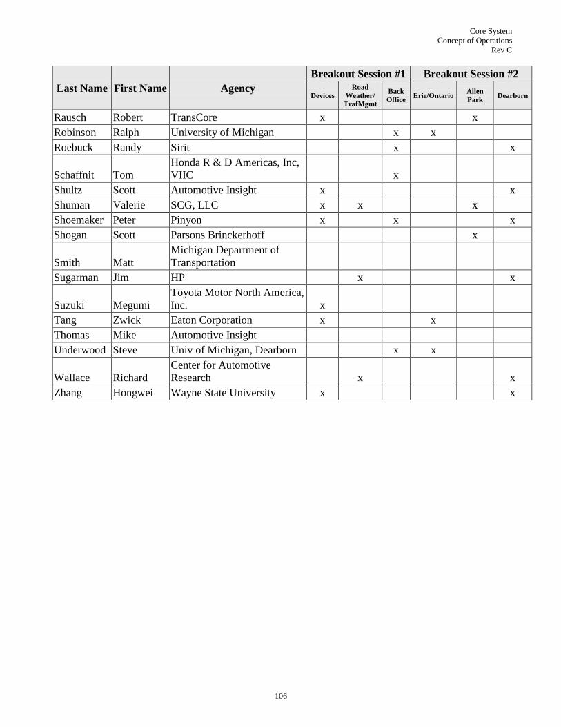
Core System
Concept of Operations
Rev C
106
Last Name First Name Agency
Breakout Session #1 Breakout Session #2
Devices
Road
Weather/
TrafMgmt
Back
Office Erie/Ontario
Allen
Park Dearborn
Rausch Robert TransCore x
x
Robinson Ralph University of Michigan
x x
Roebuck Randy Sirit
x
x
Schaffnit Tom
Honda R & D Americas, Inc,
VIIC
x
Shultz Scott Automotive Insight x
x
Shuman Valerie SCG, LLC x x
x
Shoemaker Peter Pinyon x
x
x
Shogan Scott Parsons Brinckerhoff
x
Smith Matt
Michigan Department of
Transportation
Sugarman Jim HP
x
x
Suzuki Megumi
Toyota Motor North America,
Inc. x
Tang Zwick Eaton Corporation x
x
Thomas Mike Automotive Insight
Underwood Steve Univ of Michigan, Dearborn
x x
Wallace Richard
Center for Automotive
Research
x
x
Zhang Hongwei Wayne State University x
x

Core System
Concept of Operations
Rev C
107
10.4 San Jose, CA Workshop (1 & 2 September, 2010)
Subject: San Jose, CA User Needs Workshop - Findings
Location: Doubletree San Jose
Date: Wednesday (9/1/10) and Thursday (9/2/10)
USDOT RITA:
Walt Fehr
SE project Support:
Dawn Hardesty Noblis
Jeris White Noblis
Jean Borgella Citizant
SE project Team:
Dave Binkley LM
Kathy Bonaffini LM
Larry Virgallito LM
Kevin Hunter LM
Azra Ghassemi Iteris
Tom Lusco Iteris
Participants:
Last Name First Name Agency
Breakout Session #1 Breakout
Session #2
Devices
Road
Weather/
TrafMgmt
Back
Office Carmel
Santa
Clara
Andrews Scott Cogenia Partners, LLC x
Armstrong April SAIC
x
Asuncion Robert Republic ITS
Banner Janet
Metropolitan
Transportation
Commission
x
x
Blair Kathy Alcatel-Lucent
x
Bonomi Flavio Cisco
Brandt Pete
Daimler Trucks North
America x
x
Brown Mike SwRI
x
Brown Graham Mercedes Benz Research x
Burkhard Brian HNTB Corporation
x
Campbell John Battelle
x
Cechini Frank FHWA-CADIV
x
x

Core System
Concept of Operations
Rev C
108
Last Name First Name Agency
Breakout Session #1 Breakout
Session #2
Devices
Road
Weather/
TrafMgmt
Back
Office Carmel
Santa
Clara
Chan Ching-Yao
California PATH, UC
Berkeley x
x
x
Crothers Tim FHWA
x
Day John IBM Research
Einsig Barry Harris Corporation x
x x x
Fok Edward FHWA
x
x
Francis Chris VDOT
x
Free Jake
Free Enterprises/ Go-
Light x
x
Garretson Dan Pinyon Partners
Gerges Ramez California DOT x
x
Glancy Dorothy Santa Clara University
x
x
Gledhill Jeff Verizon Business
Gwynne Gloria Caltrans x
x
Hansra Pete Caltrans
x
Huynh David City of Fremont, CA
x
Khijniak Dmitri Kapsch TrafficCom Inc. x
Koeberlein Bob
Idaho Transportation
Department
x
x
Komoda Norio Sakura Assoc
x
Koslowski Thilo Gartner
Krueger Greg
U.S. Department of
Transportation
Kruke Kevin HELP Inc./PrePass x
Leader Shel Telvent x
x x x
Manasseh Christian Mobius Logic
x
Martinez Ellen Republic ITS
McDonough Richard New York State DOT x
x
McPharlin Tom Transdyn, Inc.
x
McRae Jeff Caltrans
x
Misener Jim
University of California
PATH Program
x
Moghe Ashok Cisco Systems
x
Mortensen Steve
Federal Transit
Administration x
x
Mujumdar Sunil SQL Stream
x
x
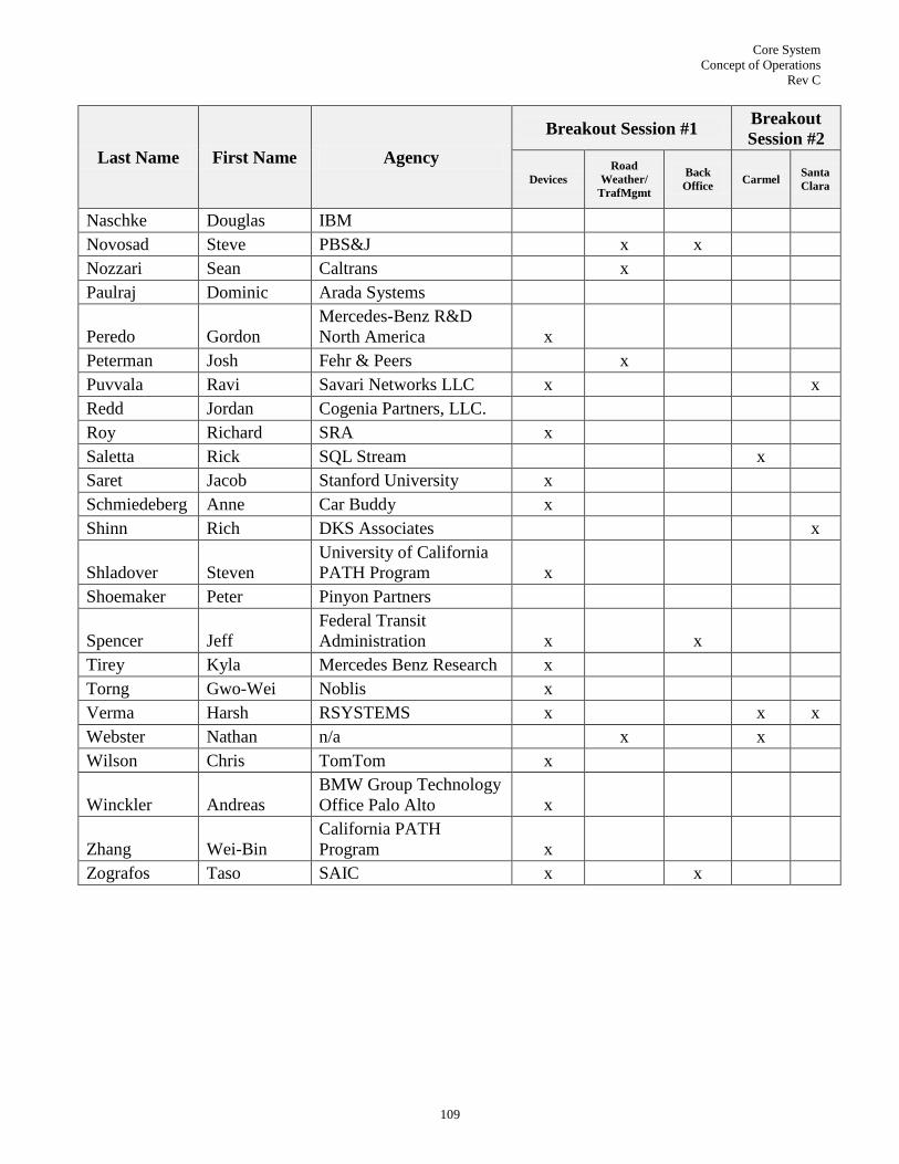
Core System
Concept of Operations
Rev C
109
Last Name First Name Agency
Breakout Session #1 Breakout
Session #2
Devices
Road
Weather/
TrafMgmt
Back
Office Carmel
Santa
Clara
Naschke Douglas IBM
Novosad Steve PBS&J
x x
Nozzari Sean Caltrans
x
Paulraj Dominic Arada Systems
Peredo Gordon
Mercedes-Benz R&D
North America x
Peterman Josh Fehr & Peers
x
Puvvala Ravi Savari Networks LLC x
x
Redd Jordan Cogenia Partners, LLC.
Roy Richard SRA x
Saletta Rick SQL Stream
x
Saret Jacob Stanford University x
Schmiedeberg Anne Car Buddy x
Shinn Rich DKS Associates
x
Shladover Steven
University of California
PATH Program x
Shoemaker Peter Pinyon Partners
Spencer Jeff
Federal Transit
Administration x
x
Tirey Kyla Mercedes Benz Research x
Torng Gwo-Wei Noblis x
Verma Harsh RSYSTEMS x
x x
Webster Nathan n/a
x
x
Wilson Chris TomTom x
Winckler Andreas
BMW Group Technology
Office Palo Alto x
Zhang Wei-Bin
California PATH
Program x
Zografos Taso SAIC x
x

Core System
Concept of Operations
Rev C
110
10.5 Washington DC Workshop (29 & 30 September, 2010)
Subject: Washington, DC User Needs Workshop - Findings
Location: The University of California Washington Center
Date: Wednesday (9/29/10) and Thursday (9/30/10)
USDOT RITA:
Walt Fehr
SE project Support:
Dawn Hardesty Noblis
Jeris White Noblis
Paul Gonzalez Noblis (Day 1)
Jean Borgella Citizant
SE project Team:
Dave Binkley LM
Kathy Bonaffini LM
Larry Virgallito LM
Kevin Hunter LM
Murty Neti LM
Cliff Heise Iteris
Tom Lusco Iteris
Participants:
Last Name First Name Agency
Breakout Session #1 Breakout
Session #2
Fleet Ops Transp
Ops
Back
Office
Rm
317
Rm
318
Abdelmename Hedhli DC LCPC x x
Armstrong Lee Armstrong Consulting x
x
Athreya Prahlad AVIS BUDGET GROUP x
x
Bayless Steven ITS America x
Body Chris Mark IV x
Bolduc Pierre Transport Canada x
x
Bowman Darrell
Virginia Tech Transportation
Institute x
Bowman Darrell
Virginia Tech Transportation
Institute x
Bruemmer David 5D Robotics x
Buckley Dan Harris Corp x
Bykins Tony LGS Innovations x x
Caldwell Stan Carnegie Mellon University x
Catlin Barbara Trans Core x

Core System
Concept of Operations
Rev C
111
Last Name First Name Agency
Breakout Session #1 Breakout
Session #2
Fleet Ops Transp
Ops
Back
Office
Rm
317
Rm
318
Chan Patrick ConSysTec x x
Coventry Antony Vaisala Inc.
x
x
Cronin Brian ITS JPO Program Lead
x
x
Curtis Deborah USDOT/ FHWA x
Edelstein Bev AmeriTrak Fleet Solutions x
x
Edelstein Jeff AmeriTrak Fleet Solutions x
x
Fawkes Larry Oracle x
Feast Laura SAIC
x
x
Free Jake Free Enterprises/ Go-Light x x
Gillis Joe Booz Allen Hamilton
x
x
Griffin Gene
Upper Great Plains
Transportation Institute
Guevara Gabe FHWA x x
Hartley Scott 5D Robotics x
x
Hatipoglu Cem
Federal Motor Carrier Safety
Administration x
Herring Alex Vaisala x x
Knapp Geoff IBI Group x x
Kurihara Thomas M.
TK Standards Management,
IEEE 1609 WG x x
Lisogorsky Leonardo New Flyer Industries x
x
MacKenzie Rod ITS America x
Messa Tyler
Consultant ISO;
Telecommunications Industry
Association x
Mueller Jonathan
Federal Motor Carrier Safety
Administration x
Murtha Suzanne Kapsch x
Park Hyungjun
Univ of VA Center for
Transportation Studies x
Parkany Emily Booz Allen Hamilton
x
x
Peters Joe FHWA x x
Pincus Marcia ITSJPO
x
x
Roberts David Temple, Inc x x
Rowe Regan 5D Robotics x
Schnacke Dick TransCore x
Slizofski Allie Drive Engineering; URS Corp x

Core System
Concept of Operations
Rev C
112
Last Name First Name Agency
Breakout Session #1 Breakout
Session #2
Fleet Ops Transp
Ops
Back
Office
Rm
317
Rm
318
Spencer Jeff FTA x
Spencer Matthew Student x
Toscano Mario Drive Engineering x
Turato John AVIS BUDGET GROUP x
x
Wagley Raj FTA/USDOT x x
Webb George Palm Beach County x x
Wilder Charlene FTA x
Wilkins PJ E-ZPass Group x x
Williams Keith D.
FHWA, Office of Safety
Integration x
Witherspoon James VDOT x
Young Steve PrePass x
Yousuf Mohammed PHWA x x

Core System
Concept of Operations
Rev C
113
10.6 San Antonio, TX Workshop (5 October, 2010)
Subject: San Antonio, TX User Needs Workshop – Findings
American Public Transportation Association (APTA) Conference.
Location: Hyatt San Antonio Hotel in San Antonio, TX, Room Presidio B
Date: Tuesday (10/05/10)
SE project Support:
Gwo-Wei Torng Noblis
SE project Team:
Dave Binkley LM
Kevin Hunter LM
Participants:
Last Name First Name Agency Transit Session
Allen Todd Route Math Software X
Bata Andrew NYC Transit X
Dow Kevin APTA X
Gangol Sharon San Antonio VIA Auditor III X
Hemily Brendon ITS America X
Hiller Bill Trapeze ITS X
Hough Jill SURTC/UGPTI X
Jackson Dave BAH X
Marraro Tony HNTB X
Reavey Patrick DIGI, Government Sales Rep X
Wetula Leo Volpe Center X
Wilson Michael Accenture X

Core System
Concept of Operations
Rev C
114
10.7 One-on-Ones Meetings
10.7.1 AERIS
Location: USDOT
Date: 9 July 2010
Participants:
USDOT RITA Walt Fehr
USDOT AERIS Marcia Pincus
USDOT AERIS Bob Ferlis
Noblis Dawn Hardesty
Noblis Jeris White
Noblis Paul Gonzalez
Noblis Jim Fisher
Citizant Jean Borgella
LM SE Team David Binkley
LM SE Team Kevin Hunter
The objective of the Applications for the Environment: Real-Time Information Synthesis (AE-
RIS) Program is to generate, acquire, and process environmentally-relevant real-time transporta-
tion data to create actionable information that supports ―green‖ transportation choices. There is a
need to monitor auto exhaust at all times, but particularly on Code Red days. The AERIS Pro-
gram would like to leverage like data already collected by the CVO and Transit programs.
10.7.2 Commercial Vehicles Operation (CVO)
Location: USDOT
Date: 31 July 2010
Participants:
USDOT RITA Walt Fehr
ITS JPO Program Lead Kate Hartman
USDOT Mike Onder
FHWA Bob Rupert
USDOT Randy Butler
USDOT FMCSA Jonathan Mueller
Noblis Dawn Hardesty
Noblis Jeris White
Citizant Jean Borgella
LM SE Team David Binkley
LM SE Team - Iteris Tom Lusco
The main focus of this meeting was to discuss how Commercial Vehicle Operations (CVO) ef-
forts would interact with this program.

Core System
Concept of Operations
Rev C
115
10.7.3 Real-Time Data Capture and Management
Location: USDOT
Date: 9 July 2010
Participants:
USDOT RITA Walt Fehr
ITS JPO Program Lead Brian Cronin
FHWA R&D Gene McHale
FHWA Office of Operations Walter During
Noblis Dawn Hardesty
Noblis Jeris White
Noblis Paul Gonzalez
Noblis Karl Wunderlich
Noblis Meenakshy Vasudevean
Citizant Jean Borgella
LM SE Team David Binkley
LM SE Team Kevin Hunter
The main focus of this meeting was to discuss what data needed to be captured to accommodate
any logging capability. This led into a discussion of how does that data need to be sent, how is it
collected, and how would it be aggregated? Brian Cronin stated that the data needed to be real-
time to be used for applications and that all data needed to be captured (no definition on what is
meant by all data).
10.7.4 Dynamic Mobility Applications
Location: USDOT
Date: 7 Oct 2010
Participants:
ITS JPO Program Lead Kate Hartman
FHWA Turner Fairbanks Ben McKeever
USDOT RITA Walt Fehr
FHWA Operations Gabe Guevara
FHWA Office of Freight Management Randy Butler
FTA Steve Mortensen
FHWA Office of Freight Management Mike Onder
JPO Greg Krueger (on the phone)
LM SE Team David Binkley
The discussion was mostly about programmatics - they are collecting ideas for ways to use data
on this program once it's collected. So far they have received 60 responses to their RFI and in-
tend to hold a workshop to present them and then issue an Request for Proposal (RFP) next year
to see who wants to do some of the more interesting apps.

Core System
Concept of Operations
Rev C
116
Randy Butler promoted the idea of web services, as they implemented with their Electronic
Freight Management project. DMA is twinned in some ways to the Data Capture Management
(DCM) project that is looking at creating the structure for the data collection environments that
then get turned into useful apps by DMA.
10.7.5 Policy
Location: USDOT
Date: 12 July 2010
Participants:
USDOT RITA Walt Fehr
USDOT ITS JPO Policy Valerie Briggs
Volpe Suzanne Sloan
Noblis Dawn Hardesty
Noblis Jeris White
Citizant Jean Borgella
LM SE Team David Binkley
LM SE Team Kathy Bonaffini
Valerie Briggs was interested in understanding the SE tasks and deliverables in the hope using
the SE ConOps input to help develop policy. The SE Team concern is that Policy is likely to ap-
ply constraints to the SE tasks/architecture. The policy schedule as of July 2010 follows:
Governance Information Technology (IT) experts will meet in Dec 2010
Identify decision making body in Jan/Feb 2011
Policy Research will continue through 2013
NHTSA will follow for another 5 years after that for rulemaking
May be 10 years before rulemaking is finalized
There was a discussion on what the need for security is and what management and oversight
would be required if needed. Also, what is the right level of privacy?
10.7.6 FHWA Road Weather Management
Location: Noblis
Date: 28 July 2010
Participants:
FHWA Road Weather Management Team Paul Pisano
USDOT RITA Walt Fehr
Noblis Chaz Harris
Noblis Dawn Hardesty
Noblis Jeris White
LM SE Team David Binkley
LM SE Team - Iteris Jeff Brummond

Core System
Concept of Operations
Rev C
117
Notes:
Public sector , private sector, transportation, weather providers
MDSS – safety and mobility
Vehicle data translator – dynamic segmentation, temp, pressure
Yaw, tire related, pavement surface condition
Translator, 2nd
version, data coming straight from the vehicle
Need safety V2V notification of pavement conditions
Vehicle as a data source, looking at CAN bus, states putting IR sensors other sensors
New project for National Center for Atmospheric Research (NCAR) 3rd
round of VDT, work
with state DOTs, calibrated IR sensor – use directly
Going to NCAR and Clarus
SAE 2735 – weather elements, weather data frame, weather report weather frame
CAN bus standards light and heavy duty OBD2 interface standard common for all vehicles,
emissions – Dave Acton working on a physical interface in right place and a standardized mes-
sage set SAE committee
3rd
phase NCAR project, point data to models, in conjunction with states, working for overall
decision support
SWR, MODSS, multi-state control strategy tool, multi-state traveler info
Next phase may tie tools to maintenance and construction decision support system
Weather responsive traffic management strategies, signal timing, ramp metering, DMS with
Battelle, gap timing, longer yellow phase – not possible in current technology
Weather data into signal controllers
Path – EAR- fully adaptive traffic control
Need to know why traffic flow is slowing
Snow removal
Aurora Pooled Fund Study, State DOT
State DOT movement of data to/from vehicle – applications
10.7.7 Standards
Location: USDOT
Date: 13 July 2010
Participants:
USDOT RITA Walt Fehr
USDOT JPO Steve Sill
Noblis Ann Diephaus
Noblis Dawn Hardesty
Noblis Jeris White
LM SE Team David Binkley
LM SE Team – Iteris Tom Lusco

Core System
Concept of Operations
Rev C
118
This program may be able to leverage some of the existing standards, but these standards may
need to be modified to accommodate data. Walt asked which interfaces need to be used as con-
trol points and the answer was look at the National ITS Architecture for guidance and the CALM
architecture could be looked at for additional standards mapping guidance.
10.7.8 Transit
Location: USDOT
Date: 12 July 2010
Participants:
USDOT RITA Walt Fehr
USDOT ITS JPO Transit Yehuda Gross
USDOT FTA Jeff Spencer
Noblis Gwo-Wei Torng
Noblis Dawn Hardesty
Noblis Jeris White
Citizant Jean Borgella
LM SE Team David Binkley
LM SE Team Kathy Bonaffini
Currently ITS devices are not integrated on transit vehicles (multiple antennas, radios) so this
program offers the potential to provide a more integrated system with greater bandwidth and real
time information. Safety information needs to be secure to protect transit agencies from litiga-
tion.
10.7.9 Cooperative Safety
Location: USDOT
Date: 26 July 2010
Participants:
USDOT RITA Walt Fehr
USDOT ITS JPO Mike Schagrin
Noblis Dawn Hardesty
Noblis Jeris White
Citizant Jean Borgella
LM SE Team Kathy Bonaffini
LM SE Team – Iteris Tom Lusco
This meeting mainly identified the key individuals the SE team should contact.

Core System
Concept of Operations
Rev C
119
10.8 Consolidated User Input
This table represents the various user input from the workshops, one-on-ones, other venues, and documents.
Table 10-1. Consolidated User Input
#
Trip
Rpt
ID
Source
Type Source Problem Need Rationale
1 1, 2,
3, 5, 6, 22,
23
Workshop Vancouver Limited roadway performance data is available. Provide the data to enable more sophisticated me-
thods of traffic control (e.g. adaptive signals).
With more spatially comprehensive real-
time data, we can operate signals better, increasing mobility through intersections
constrained by signals.
2 4 Workshop Vancouver Enforcement of HOT/HOV, prioritization of multi-passenger vehicles is difficult and man-
power intensive.
Provide the occupancy status of each individual vehicle to the operators of roadways where such
information is relevant.
Optimizing road network performance includes prioritization by number of ve-
hicle occupants. Moving two people helps
the network more than moving one.
3 7 Workshop Vancouver We can't store and access all the roadway per-formance data that we want.
Provide a way for us to access historical and real-time roadway performance data for every time of
day, day of year, special event condition.
Better historical data will allow more effective signal timing.
4 8,9 Workshop Vancouver Detection of roadway incidents requires manual authentication.
Provide data or information sufficient to determine the existence and location of a roadway incident.
Automated incident detection will de-crease response time of safety agents and
decrease manpower requirement for traffic
management.
5 10 Workshop Vancouver Failure of roadside infrastructure is not automat-ically detected
6 11 Workshop Vancouver Limited road weather information is available. Provide road weather information, particularly in
areas near traffic signals.
Better road weather information, particu-
larly in areas near traffic signals, would enable more effective traffic management,
signal timing in particular.
7 12 Workshop Vancouver Signalized intersections often have no under-
standing of the pedestrian situation.
Provide a mechanism for detecting and distributing
numbers and locations of pedestrians.
Better understanding of the real time pe-
destrian situation will improve traffic
management; historical information will
allow better informed signal timings.
8 13 Workshop Vancouver Signalized intersections do not detect cyclists. Provide a mechanism for detecting and distributing numbers and locations of cyclists.
Detecting cyclists will allow signalized intersections to accommodate them in
timing.
9 14 Workshop Vancouver Signalized intersections do not detect trains far enough in advance to accommodate the exten-
sive red time due to train passage.
Provide a means for identifying the speeds and locations of trains well in advance of roadway cross-
ings.
Better knowledge of when trains will affect traffic will allow management of
traffic to compensate for the long red time
that occurs when the train passes.
10 16 Workshop Vancouver Signalized intersections do not detect transit vehicles as anything other than a vehicle and so
cannot manage them with higher priority.
Provide a means for locating transit vehicles far enough in advance of traffic signals to allow mod-
ification of timing.
Prioritization of transit vehicles provides better net throughput.
11 17 Workshop Vancouver Even when we know a transit vehicle is coming, we don't know the passenger count.
Provide the passenger count for transit vehicles to the signal controller at signalized intersections the
vehicle approaches.
Prioritize vehicles with passengers.
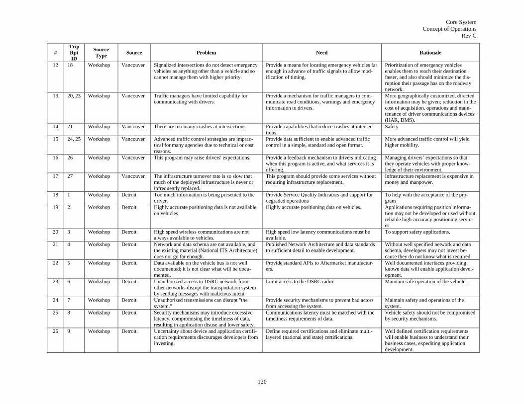
Core System
Concept of Operations
Rev C
120
#
Trip
Rpt
ID
Source
Type Source Problem Need Rationale
12 18 Workshop Vancouver Signalized intersections do not detect emergency
vehicles as anything other than a vehicle and so cannot manage them with higher priority.
Provide a means for locating emergency vehicles far
enough in advance of traffic signals to allow mod-ification of timing.
Prioritization of emergency vehicles
enables them to reach their destination faster, and also should minimize the dis-
ruption their passage has on the roadway
network.
13 20, 23 Workshop Vancouver Traffic managers have limited capability for communicating with drivers.
Provide a mechanism for traffic managers to com-municate road conditions, warnings and emergency
information to drivers.
More geographically customized, directed information may be given; reduction in the
cost of acquisition, operations and main-tenance of driver communications devices
(HAR, DMS).
14 21 Workshop Vancouver There are too many crashes at intersections. Provide capabilities that reduce crashes at intersec-
tions.
Safety
15 24, 25 Workshop Vancouver Advanced traffic control strategies are imprac-
tical for many agencies due to technical or cost
reasons.
Provide data sufficient to enable advanced traffic
control in a simple, standard and open format.
More advanced traffic control will yield
higher mobility.
16 26 Workshop Vancouver This program may raise drivers' expectations. Provide a feedback mechanism to drivers indicating when this program is active, and what services it is
offering.
Managing drivers‘ expectations so that they operate vehicles with proper know-
ledge of their environment.
17 27 Workshop Vancouver The infrastructure turnover rate is so slow that
much of the deployed infrastructure is never or
infrequently replaced.
This program should provide some services without
requiring infrastructure replacement.
Infrastructure replacement is expensive in
money and manpower.
18 1 Workshop Detroit Too much information is being presented to the
driver.
Provide Service Quality Indicators and support for
degraded operations
To help with the acceptance of the pro-
gram
19 2 Workshop Detroit Highly accurate positioning data is not available
on vehicles
Highly accurate positioning data on vehicles. Applications requiring position informa-
tion may not be developed or used without
reliable high-accuracy positioning servic-es.
20 3 Workshop Detroit High speed wireless communications are not
always available to vehicles.
High speed low latency communications must be
available.
To support safety applications.
21 4 Workshop Detroit Network and data schema are not available, and the existing material (National ITS Architecture)
does not go far enough.
Published Network Architecture and data standards to sufficient detail to enable development.
Without well specified network and data schema, developers may not invest be-
cause they do not know what is required.
22 5 Workshop Detroit Data available on the vehicle bus is not well documented; it is not clear what will be docu-
mented.
Provide standard APIs to Aftermarket manufactur-ers.
Well documented interfaces providing known data will enable application devel-
opment.
23 6 Workshop Detroit Unauthorized access to DSRC network from
other networks disrupt the transportation system by sending messages with malicious intent.
Limit access to the DSRC radio. Maintain safe operation of the vehicle.
24 7 Workshop Detroit Unauthorized transmissions can disrupt "the
system."
Provide security mechanisms to prevent bad actors
from accessing the system.
Maintain safety and operations of the
system.
25 8 Workshop Detroit Security mechanisms may introduce excessive latency, compromising the timeliness of data,
resulting in application disuse and lower safety.
Communications latency must be matched with the timeliness requirements of data.
Vehicle safety should not be compromised by security mechanisms.
26 9 Workshop Detroit Uncertainty about device and application certifi-cation requirements discourages developers from
investing.
Define required certifications and eliminate multi-layered (national and state) certifications.
Well defined certification requirements will enable business to understand their
business cases, expediting application
development.

Core System
Concept of Operations
Rev C
121
#
Trip
Rpt
ID
Source
Type Source Problem Need Rationale
27 10 Workshop Detroit Vehicles may end up with many different devic-
es to support different applications.
Provide an integrating structure that enables mul-
tiple applications on a single device.
The fewer devices required, the more
applications individuals may feel are available to them.
28 11 Workshop Detroit Current message set definition does not provide
a sufficient level of detail to enable all of the
envisioned applications.
Define a new message that includes additional in-
formation.
More data will allow faster development
of basic applications and provide oppor-
tunities for more advanced applications.
29 12 Workshop Detroit Transportation system infrastructure may be
limited in availability in some geographic areas.
Use V2V propagation to enable some safety applica-
tions.
To reduce the reliance of safety applica-
tions on potentially unavailable infrastruc-
ture.
30 13 Workshop Detroit This program‘s deployment strategy lacks clari-
ty, creating uncertainty with stakeholders.
Define the deployment strategy. Reducing or removing uncertainty for
stakeholders will remove one barrier to
investment.
31 14 Workshop Detroit Research data is difficult to acquire. Provide a centralized means for making research data available.
To provide increased confidence in dep-loyment.
32 1 Workshop Detroit We don't have traffic data beyond instrumented
freeways, limiting our understanding of traffic conditions.
Comprehensive road network traffic data, including
vehicle speed, vehicle count, origin and destination.
With comprehensive road network traffic
data, we could better manage traffic, and save money by not having to install new
infrastructure-based sensors.
33 1 Workshop Detroit Planning needs require long-term storage of
traffic condition information.
A repository to hold the comprehensive traffic data,
including vehicle speed, vehicle count, origin and destination.
A repository will enable the planning and
asset management processes to provide better outputs in the future.
34 2 Workshop Detroit Traffic data needs to be analyzed/synthesized in
order to be useful.
A standardized method for accessing and processing
data in order to produce useful information for traf-fic management, possibly an open data warehouse.
In order to be useful, data has to be ana-
lyzed and turned into information. This program could produce a lot of data, and
turning it into information could be a
significant task.
35 3 Workshop Detroit A high fuel consumption rate is harmful to the environment.
Increase mobility by providing means to enable signal optimization and flow coordination, allowing
vehicles to minimize start/stop.
Start/stop causes large fuel consumption, increasing emissions; decreasing start stop
will benefit the environment.
36 4 Workshop Detroit Driver expectations are based on typical condi-tions, and do not account for anomalies such as
incidents or bad weather.
Monitor traffic flow to see if there are any road closings or other related information.
….because it can
37 4 Workshop Detroit Driver expectations are based on typical condi-tions, and do not account for anomalies such as
incidents or bad weather.
Push advisory of weather information to a selective set of drivers within an affected area.
….because it can
38 4 Workshop Detroit Driver expectations are based on typical condi-
tions, and do not account for anomalies such as incidents or bad weather.
Provide accurate and timely geographical weather
and road surface condition data.
….because it can
39 5 Workshop Detroit Incidents in rural environments are common but
response delay is higher than in urban areas.
Provide vehicle information when needed, emergen-
cy information including mayday, to an emergency responder contact.
Providing an On-Star-like May Day ser-
vice for all drivers would save lives.
40 6 Workshop Detroit Evacuating vehicles is uncoordinated with no
dynamic route guidance.
Provide situational awareness of the mobility envi-
ronment for evacuations.
This program offers the potential for im-
proving situational awareness to a greater
degree than any other available solution.
41 7 Workshop Detroit Road weather and surface condition information
is not comprehensive, being known only at select
RWIS sites.
Provide more comprehensive weather and surface
condition data sourced from vehicles, including
temperature, wiper usage, traction control and ABS events.
Additional data would enable and streng-
then many possible applications, but at
minimum improve weather forecasting and observing.
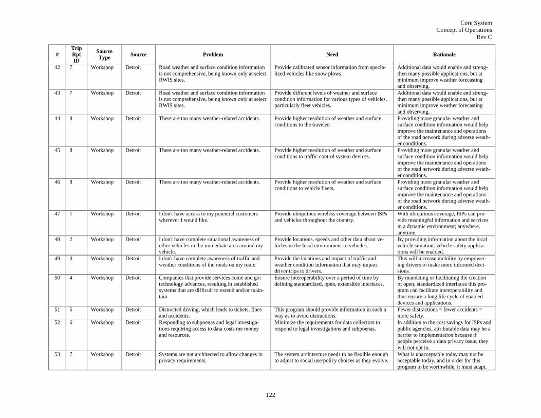
Core System
Concept of Operations
Rev C
122
#
Trip
Rpt
ID
Source
Type Source Problem Need Rationale
42 7 Workshop Detroit Road weather and surface condition information
is not comprehensive, being known only at select RWIS sites.
Provide calibrated sensor information from specia-
lized vehicles like snow plows.
Additional data would enable and streng-
then many possible applications, but at minimum improve weather forecasting
and observing.
43 7 Workshop Detroit Road weather and surface condition information
is not comprehensive, being known only at select RWIS sites.
Provide different levels of weather and surface
condition information for various types of vehicles, particularly fleet vehicles.
Additional data would enable and streng-
then many possible applications, but at minimum improve weather forecasting
and observing.
44 8 Workshop Detroit There are too many weather-related accidents. Provide higher resolution of weather and surface conditions to the traveler.
Providing more granular weather and surface condition information would help
improve the maintenance and operations
of the road network during adverse weath-er conditions.
45 8 Workshop Detroit There are too many weather-related accidents. Provide higher resolution of weather and surface
conditions to traffic control system devices.
Providing more granular weather and
surface condition information would help improve the maintenance and operations
of the road network during adverse weath-
er conditions.
46 8 Workshop Detroit There are too many weather-related accidents. Provide higher resolution of weather and surface
conditions to vehicle fleets.
Providing more granular weather and
surface condition information would help
improve the maintenance and operations
of the road network during adverse weath-er conditions.
47 1 Workshop Detroit I don't have access to my potential customers
wherever I would like.
Provide ubiquitous wireless coverage between ISPs
and vehicles throughout the country.
With ubiquitous coverage, ISPs can pro-
vide meaningful information and services in a dynamic environment; anywhere,
anytime.
48 2 Workshop Detroit I don't have complete situational awareness of
other vehicles in the immediate area around my vehicle.
Provide locations, speeds and other data about ve-
hicles in the local environment to vehicles.
By providing information about the local
vehicle situation, vehicle safety applica-tions will be enabled.
49 3 Workshop Detroit I don't have complete awareness of traffic and
weather conditions of the roads on my route.
Provide the locations and impact of traffic and
weather condition information that may impact driver trips to drivers.
This will increase mobility by empower-
ing drivers to make more informed deci-sions.
50 4 Workshop Detroit Companies that provide services come and go;
technology advances, resulting in established systems that are difficult to extend and/or main-
tain.
Ensure interoperability over a period of time by
defining standardized, open, extensible interfaces.
By mandating or facilitating the creation
of open, standardized interfaces this pro-gram can facilitate interoperability and
thus ensure a long life cycle of enabled
devices and applications.
51 5 Workshop Detroit Distracted driving, which leads to tickets, fines and accidents.
This program should provide information in such a way as to avoid distractions.
Fewer distractions = fewer accidents = more safety.
52 6 Workshop Detroit Responding to subpoenas and legal investiga-
tions requiring access to data costs me money and resources.
Minimize the requirements for data collectors to
respond to legal investigations and subpoenas.
In addition to the cost savings for ISPs and
public agencies, attributable data may be a barrier to implementation because if
people perceive a data privacy issue, they
will not opt in.
53 7 Workshop Detroit Systems are not architected to allow changes in privacy requirements.
The system architecture needs to be flexible enough to adjust to social use/policy choices as they evolve.
What is unacceptable today may not be acceptable today, and in order for this
program to be worthwhile, it must adapt.

Core System
Concept of Operations
Rev C
123
#
Trip
Rpt
ID
Source
Type Source Problem Need Rationale
54 8 Workshop Detroit Interoperability between devices. All interfaces should be publicly defined and open;
mandatory standards should be defined for every interface.
Standardization will avoid issues asso-
ciated with being locked into proprietary systems.
55 8 Workshop Detroit Interoperability between devices. All interfaces should be publicly defined and open;
mandatory standards should be defined for every
interface.
Standardization will avoid issues asso-
ciated with being locked into proprietary
systems.
56 9 Workshop Detroit Road congestion due to accidents and construc-
tion is not reported in such a way that drivers
know their optimal routes.
Provide traveler information to travelers more effi-
ciently, telling them accident locations, alternate
routes, recommended routes and alternate mode information.
More efficient dissemination of traveler
information will increase mobility; exist-
ing services such as MapQuest are limited, particularly in multi-modal choices.
57 10 Workshop Detroit We don't have a way to authenticate safety mes-
sages.
Provide a mechanism for the authentication of safety
messages.
Safety applications must trust their inputs.
58 11 Workshop Detroit We don't have a way to ensure anonymi-ty/privacy of safety messages.
Safety messages must be anonymized. If we don't ensure anonymity, it will be difficult to protect privacy.
59 12 Workshop Detroit We don't have a way to ensure delivery of safety
messages in real time.
Need to ensure the delivery of safety messages in
real-time.
Safety messages must be delivered in time
for them to be acted upon, which is often quite quickly.
60 13 Workshop Detroit Certain services may monopolize the stream of
information the driver/traveler, preventing other
services from gaining access.
Provide a means for balancing the flow of informa-
tion between various services.
Flood of information from various servic-
es is not fair to other services.
61 14 Workshop Detroit Vehicles often do not know their absolute posi-
tion or relative position with sufficient accuracy
to enable applications.
Provide lane-level accuracy to vehicles. Knowing where you are is critical to many
applications, particularly safety applica-
tions.
62 15 Workshop Detroit Safety applications require the most recent map data, including 3D map data.
This program should provide up-to-date 3D digital maps to vehicles.
Maps must be kept up to date with con-struction and maintenance changes, and
experience has shown that customers with
navigation units do not generally do this on their own.
63 16 Workshop Detroit Driver may not know whether or not his installed
safety applications are supported in a given area.
Provide a means for informing the driver when
various active safety applications depending on local wireless communications (DSRC, including
5.9) is functioning or not functioning.
Managing the drivers' expectations is
critical to him being able to safely operate the vehicle.
64 17 Workshop Detroit Road condition information is often received too late for the driver to properly react to it.
Need to provide drivers with advance warning of road conditions that may impact their safety in time
for them to act on it.
Safety is compromised by late information delivery.
65 18 Workshop Detroit I don't have any way of preventing data that I
transmit wirelessly from being accessed by oth-ers.
Need to provide a means for encrypting data that is
transferred.
Without encryption, personal transaction
data may be received by the wrong people.
66 19 Workshop Detroit Privacy safeguard design difficulties are slowing
down deployment.
(Possibly all) applications, but certainly some
should be Opt-in.
Allows the system to be deployed by
bypassing privacy concerns; customers that are concerned about privacy will not
install compromising applications.
67 20 Workshop Detroit My applications require raw data. Need standardized output of data to facilitate collec-
tion and processing.
To provide a level playing field for service
providers to provide value added services as information processors.
68 Workshop Detroit Provide sufficient functionality to eliminate lane
markings
Provide information normally presented by lane
markings to the vehicle.
69 Workshop Detroit Provide sufficient functionality to eliminate signalized intersections
Provide arbitration for intersection access.
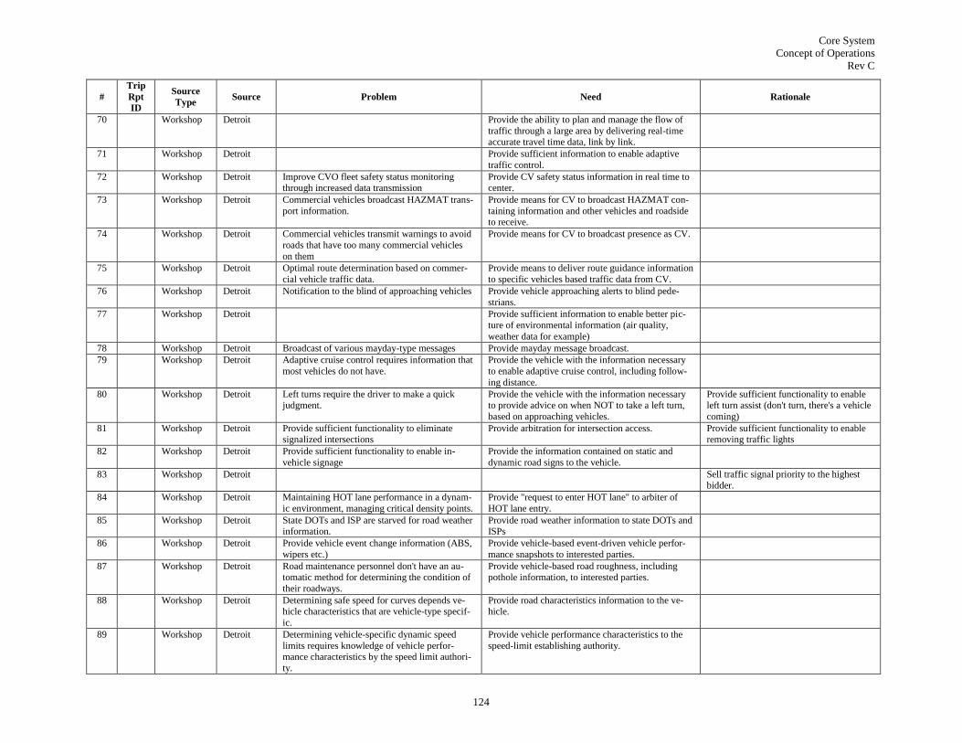
Core System
Concept of Operations
Rev C
124
#
Trip
Rpt
ID
Source
Type Source Problem Need Rationale
70 Workshop Detroit Provide the ability to plan and manage the flow of
traffic through a large area by delivering real-time accurate travel time data, link by link.
71 Workshop Detroit Provide sufficient information to enable adaptive
traffic control.
72 Workshop Detroit Improve CVO fleet safety status monitoring through increased data transmission
Provide CV safety status information in real time to center.
73 Workshop Detroit Commercial vehicles broadcast HAZMAT trans-
port information.
Provide means for CV to broadcast HAZMAT con-
taining information and other vehicles and roadside to receive.
74 Workshop Detroit Commercial vehicles transmit warnings to avoid
roads that have too many commercial vehicles
on them
Provide means for CV to broadcast presence as CV.
75 Workshop Detroit Optimal route determination based on commer-
cial vehicle traffic data.
Provide means to deliver route guidance information
to specific vehicles based traffic data from CV.
76 Workshop Detroit Notification to the blind of approaching vehicles Provide vehicle approaching alerts to blind pede-
strians.
77 Workshop Detroit Provide sufficient information to enable better pic-
ture of environmental information (air quality,
weather data for example)
78 Workshop Detroit Broadcast of various mayday-type messages Provide mayday message broadcast.
79 Workshop Detroit Adaptive cruise control requires information that
most vehicles do not have.
Provide the vehicle with the information necessary
to enable adaptive cruise control, including follow-
ing distance.
80 Workshop Detroit Left turns require the driver to make a quick judgment.
Provide the vehicle with the information necessary to provide advice on when NOT to take a left turn,
based on approaching vehicles.
Provide sufficient functionality to enable left turn assist (don't turn, there's a vehicle
coming)
81 Workshop Detroit Provide sufficient functionality to eliminate signalized intersections
Provide arbitration for intersection access. Provide sufficient functionality to enable removing traffic lights
82 Workshop Detroit Provide sufficient functionality to enable in-
vehicle signage
Provide the information contained on static and
dynamic road signs to the vehicle.
83 Workshop Detroit Sell traffic signal priority to the highest bidder.
84 Workshop Detroit Maintaining HOT lane performance in a dynam-
ic environment, managing critical density points.
Provide "request to enter HOT lane" to arbiter of
HOT lane entry.
85 Workshop Detroit State DOTs and ISP are starved for road weather information.
Provide road weather information to state DOTs and ISPs
86 Workshop Detroit Provide vehicle event change information (ABS,
wipers etc.)
Provide vehicle-based event-driven vehicle perfor-
mance snapshots to interested parties.
87 Workshop Detroit Road maintenance personnel don't have an au-tomatic method for determining the condition of
their roadways.
Provide vehicle-based road roughness, including pothole information, to interested parties.
88 Workshop Detroit Determining safe speed for curves depends ve-hicle characteristics that are vehicle-type specif-
ic.
Provide road characteristics information to the ve-hicle.
89 Workshop Detroit Determining vehicle-specific dynamic speed
limits requires knowledge of vehicle perfor-mance characteristics by the speed limit authori-
ty.
Provide vehicle performance characteristics to the
speed-limit establishing authority.

Core System
Concept of Operations
Rev C
125
#
Trip
Rpt
ID
Source
Type Source Problem Need Rationale
90 Workshop Detroit Establish various roles and levels of security for
different types of users
Provide role-based security. Enables various levels of permission for
different types of users.
91 Workshop Detroit Deployment Provide an architecture that allows small deploy-ments in limited geographic areas to accomplish
specific goals.
Investors may be willing to put infrastruc-ture out there based on certain geogra-
phies; e.g., border wait times.
92 Workshop Detroit Pedestrians slow down traffic flow. Provide locations of pedestrian crossings with pede-strian traffic to vehicles in real-time.
By identifying active pedestrian crossings, this information could be passed to ve-
hicles that could choose to avoid those
locations, thus improving mobility for all parties.
93 Workshop Detroit Provide automatic pedestrian crossing signalization,
without having to wait for pedestrians to trigger by pressing a button.
If there were some higher level under-
standing of pedestrian flow (beyond just at a single intersection), pedestrian platoons
could be managed, increasing mobility.
94 Workshop Detroit Provide turning movement counts at inter-
sections.
95 Workshop Detroit Maintenance and construction workers are en-
dangered by passing traffic.
Provide maintenance and construction worker loca-
tion information to nearby vehicles.
96 Workshop Detroit Pedestrians are endangered by passing traffic. Provide pedestrian location information to nearby
vehicles.
97 Workshop Detroit In-vehicle PDAs should function as ve-
hicles, once exiting a vehicle, change
mode back to pedestrian
98 Workshop Detroit Provide personal origin-destination information Even better than vehicle O-D, since you get a personal start and end.
99 Workshop Detroit Provide walk request for pedestrian crossings
through PDA.
100 Workshop Detroit Visually impaired pedestrians don't know where vehicles are, and thus don't know when they are
at risk.
Provide the locations of surrounding vehicles to PDAs.
For the blind, detect other broadcasters around you, to act as a "seeing eye hand-
set"
101 Workshop Detroit Provide transit operators with understanding of
how many people are queued at a stop.
Provide information from transit stops to transit
operators.
102 Workshop Detroit Slugs don't have a standardized, authenticated
mechanism of finding riders/rides.
Enable secure, person-to-person slug O/D informa-
tion exchange.
103 Workshop Detroit Locally relevant safety information is difficult to obtain.
Provide safety messages from a vehicle to applica-tion (roadside or center).
Provide safety messages with localized, specific content.
104 Workshop Detroit Locally relevant safety information is difficult to
obtain.
Provide safety messages from a vehicle to applica-
tion (roadside or center).
Provide advisory messages with localized,
specific content.
105 Workshop Detroit Maintenance and construction workers are en-dangered by passing traffic.
Provide maintenance and construction worker loca-tion information to nearby vehicles.
Provide work zone warning information when workers are present and working
and traffic is approaching.
106 Workshop Detroit Businesses can't attract as many customers as
they would like.
Provide generalized indication of potential customer
locations to businesses, based on PDA locations.
Use localized broadcast to offer commer-
cial services to attract customers (e.g.,
$.50 off coupon at Starbucks)
107 Workshop Detroit Businesses can't attract as many customers as
they would like.
Provide generalized indication of potential customer
locations to businesses, based on PDA locations.
Use commercial needs about customer
locations and demands to create a market such than aggregator would collect cus-
tomer location and time data and resell

Core System
Concept of Operations
Rev C
126
#
Trip
Rpt
ID
Source
Type Source Problem Need Rationale
108 Workshop Detroit Public safety deployments usually done based on
non-real time statistics, depend on dispatch re-sponse.
Provide safety messages from a vehicle to applica-
tion (roadside or center).
By spotting trouble spots, which is done
with statistical analysis post-real-time today, police could get more timely infor-
mation and respond far more quickly.
109 Workshop Detroit Identify the locations of stops, schools and
curves
Provide road and road context (stops, schools, etc.)
information to vehicles.
110 Workshop Detroit Provide direction-based speed warnings
111 Workshop Detroit Avalanche and other local natural disaster-like
warnings
Provide natural disaster information relevant to the
vehicle's future route to vehicles.
112 Workshop Detroit Distribute surface condition information to ve-hicles
Provide surface condition information relevant to the vehicle's future route to vehicles.
113 Workshop Detroit Distribute GPS differential corrections Provide information from external non-ITS sources
e.g., differential GPS corrections, timing) to ve-hicles.
114 Workshop Detroit Provide advance warning of congestion Provide congestion information relevant to the ve-
hicle's future route to vehicles.
115 Workshop Detroit Provide railroad crossing information (when it will be blocked and on what roadways)
Provide railroad crossing and blockage information to vehicles for the vehicle's future route.
116 Workshop Detroit Provide alert to vehicle when a train is coming along
the route the vehicle is traveling.
117 Workshop Detroit Provide roadside information even for vehicles many hours away
118 Workshop Detroit Warning of bad drivers around you Provide safety messages from a vehicle to applica-
tion (roadside or center) in real-time.
119 Workshop Detroit Warning of bad drivers around you Provide information describing location and charac-teristics of "bad driving" vehicles to vehicles in real-
time.
120 Workshop Detroit Provide variable lane control information to vehicles
during high volume conditions, for vehicles on or approaching variable lane-enabled roadways.
121 Workshop Detroit Forecasting during high-volume conditions, for
example where to park for large events
Provide near-real time parking information to ve-
hicles en-route.
122 Workshop Detroit Warn of maintenance work or lane closures Provide lane closure information to vehicles on or near closed lanes.
123 Workshop Detroit Warn other vehicles of snowplow locations Provide locations of snow plows to vehicles in area.
124 Workshop Detroit Broadcast safety-related information, particularly for incident management; consider using emer-
gency vehicles as broadcasters.
Provide incident-related information to vehicles that may be impacted by the incident
125 Workshop Detroit Warnings to trucks of where to get off because
of bridge constraints
Provide bridge/tunnel constraint information to
vehicles upstream of restrictive entry.
126 Workshop Detroit Warn of maintenance work or lane closures Provide construction information, including lane
closure information to vehicles on or near closed
lanes.
Updated construction information, includ-
ing lane closures
127 Workshop Detroit Curve data activate if relevant to the vehicle and route
Provide curve characteristics data to vehicles up-stream of curve.
128 Workshop Detroit SPAT, so that vehicles can be programmed
ahead of time to adjust speed accordingly
Provide real-time information (SPAT) from roadside
devices to vehicles.
129 Workshop Detroit VMS content, in-vehicle signage of DMS Note: language customization

Core System
Concept of Operations
Rev C
127
#
Trip
Rpt
ID
Source
Type Source Problem Need Rationale
130 Workshop Detroit Alert people of open parking spaces to encour-
age alternate mode use
Provide parking space information near alternate
modes to vehicles in the area.
131 Workshop Detroit Provide messages to cyclists indicating best locations to cross the road.
Provide local safety routing and road crossing in-formation to cyclists.
132 Workshop Detroit HAZMAT information
133 Workshop Detroit Blind spots could provide information to pede-
strians and bicyclists.
Provide local safety routing and road crossing in-
formation to pedestrians and cyclists.
134 Workshop Detroit For roundabouts with 3 lanes, rebroadcast
vehicle HIA to pedestrians.
135 Workshop Detroit Provide SPAT and personal location information to the blind
To assist the blind in crossing intersec-tions
136 Workshop Detroit Broadcast when next bus is available. Provide real-time transit information to mobile
users.
137 Workshop Detroit Distribute the CRL
138 Workshop Detroit Provide vehicle locations to vehicles in immediate area.
To assist when there are several vehicles approaching an intersection and one of
them may not have visibility into all other
vehicles.
139 Workshop Detroit Global standardization is needed for software (inter-
faces and certain services).
Standardization will avoid issues asso-
ciated with being locked into proprietary
systems.
140 Workshop Detroit Certification is needed
141 Workshop Detroit Traffic information
142 Workshop Detroit Provide ADT and OD information to centers. Saves putting out counters, long term
money savings
143 Workshop Detroit Provide secure financial transaction between vehicle and toll authority for dynamic pricing
Road pricing, charge based on time of day, congestion, lane used, priority access,
rural or urban road, #occupants
144 Workshop Detroit Automated parking Provide secure financial transaction between vehicle
and parking authority for automated parking as-signment/charging
145 Workshop Detroit Request for identification of parking space,
availability of certain types of parking spaces (handicapped, visitor); guide vehicle to parking
spot
Provide parking space characteristic information
from roadside or center to vehicle, including routing information.
146 Workshop Detroit Electronic screening, weigh-in-motion Provide secure transactions to enable the exchange of CV information sufficient to conduct weigh-in-
motion/electronic screening
147 Workshop Detroit Permitting Provide secure transactions to enable CVs to apply
for and receive permits electronically.
148 Workshop Detroit Vehicle condition monitoring Provide the exchange of vehicle condition informa-
tion from vehicles to centers.
149 Workshop Detroit Provide WIM information to public safety vehicles. Send WIM information to public safety
vehicle to have them intercept vehicle
150 Workshop Detroit Provide secure exchanges to enable limited remote
control of HAZMAT vehicles
HAZMAT monitoring, tracking, remote
disabling
151 Workshop Detroit Transit connection protection: vehicle to vehicle
connections
Enable the exchange of transit vehicle messages to
ensure protection: occupancy, arrival times.

Core System
Concept of Operations
Rev C
128
#
Trip
Rpt
ID
Source
Type Source Problem Need Rationale
152 Workshop Detroit Visibility into location of buses and schedule
adherence
Provide the locations of buses and schedule adhe-
rence to centers.
153 Workshop Detroit HIA at bus stop, next bus at, passenger awaiting Provide notification to transit vehicles of status of stops, location of potential passengers.
154 Workshop Detroit Dynamic ride matching (slugging) Secure exchange of ride-sharing information, in-
cluding personal authentication.
155 Workshop Detroit OnStar-like crash notification and emergency
dispatch
Provide notification of an accident directly from
vehicle to emergency responders.
156 Workshop Detroit Transmit diagnostics from crashed vehicle. Provide exchange of diagnostic information between
crashed vehicle, emergency responders.
157 Workshop Detroit Police car send messages directly to vehicle it is
pursuing.
Enable secure exchange between police and pursued
vehicle.
158 Workshop Detroit Commercial vehicle overnight parking request
and sale.
Provide location, routing and payment for CV park-
ing.
Improve use of existing parking infrastruc-
ture, meet need of CVO community at the same time.
159 Workshop Detroit Monitor and report if CV drivers are getting
sufficient rest
Provide exchange of in-cab sensory data between
CV and center
160 Workshop Detroit Provide locations of all freight between CV and center.
Monitor freight locations; in the case of a natural disaster, prioritize removal of
freight by location and type. Improve
disaster response, saving money in lost goods.
161 Workshop Detroit Weigh-in-motion, truck/driver log, cross-
border clearance.
162 Workshop Detroit Provide enforcement-related vehicle operating cha-racteristics to enforcement agency
Electronic enforcement
163 Workshop Detroit Management of truck routing when trucks oper-
ate in hazardous environments, e.g. ice road truckers
Provide routing information to CV in hazardous
environments.
164 Workshop Detroit Paratransit support where vehicle communicates
location to dispatcher and vice-versa
Exchange paratransit location information with
center.
165 Workshop Detroit Weather-related warnings to specifically affected parties, guaranteed delivery
Provide weather-related warnings directly to those likely to be affected.
166 Workshop Detroit Identify vehicles on approach to signal, schedule
vehicle to hold green longer for increased weight vehicles.
Provide vehicle weight, acceleration and other per-
formance characteristics to signal.
Modify timing to account for performance
of HVs.
167 Workshop Detroit Ferry ticketing Exchange payment information between boarder
and ferry operator.
168 Workshop Detroit Provide longer pedestrian crossing times for disabled/aged pedestrians
Communicate disabled/aged pedestrian location and destination to signal.
169 Workshop Detroit Bike-to-bike collision avoidance
170 Workshop Detroit Other reservation-like activities: doctor appoint-
ments, ferry reservations, rest, etc.
Provide for exchange of 3rd party reservation in-
formation.
Workshop Detroit Cyclists don't trigger signals. Provide bike-to-signalized intersection data ex-change.
171 Workshop Detroit Cyclists can't always find a bike with a bike rack Provide for exchange of information between cyclist
and transit: I want a bus with a bike rack; bus re-sponds with status, and if not available with the
nearest bus that does have space and a rack.

Core System
Concept of Operations
Rev C
129
#
Trip
Rpt
ID
Source
Type Source Problem Need Rationale
172 Workshop Detroit Provide border wait times to travelers that are re-
mote
173 Workshop Detroit Cyclist or disabled pedestrian request green signal from traffic light.
Communicate cyclist or disabled/aged pedestrian location and destination to signal.
174 1 Workshop San Jose Safety applications are constrained by the limited
range of DSRC, which is itself constrained by antenna placement.
The DOT needs to sponsor additional research into
the optimal placement and number of DSRC radios and antennas for large vehicle types.
Antenna placement becomes a serious
constraint on large vehicles, where the vehicle itself can occlude transmissions.
175 2 Workshop San Jose Vehicles sizes are not uniform. On-board safety systems need to be able to identify
vehicle envelope.
Collision avoidance applications will care
about the edges of the vehicle, not the middle.
176 3 Workshop San Jose Many commercial and transit vehicles have too
many stand-alone devices on board already.
This program needs to establish standards and inter-
face designs to enable developers to create inte-
grated platforms.
Having integrated systems will increase
acceptance, reduce driver workload and
thereby increase safety.
177 4 Workshop San Jose Vehicles may change their size envelope over
the course of a trip (adding a trailer, extending
cargo beyond the length of the bed, etc.)
Devices with on-board vehicle characteristics sys-
tems need to be able to adapt to changes in the ve-
hicle envelope automatically without requiring operator intervention.
Without correct information on the vehicle
envelope, on-board systems may send
incorrect safety messages.
178 5 Workshop San Jose Evolutionary rollouts imply that multiple ver-
sions of onboard and roadside equipment will
exist, raising incompatibility challenges.
The system needs to ensure backwards compatibility
to accommodate devices that are deployed over
different timeframes.
Safety systems deployed over time need to
be aware of older systems so they can
work together.
179 6 Workshop San Jose Train location transmissions are not included in
any current system specification.
This system needs to provide a mechanism for the
reception of rail location transmissions.
We need train positioning information to
enable rail collision avoidance.
180 7 Workshop San Jose Devices may become outdated as standards and
requirements change.
This program needs to establish standards and poli-
cy to ensure that devices are built to open standards that can be upgraded as technology changes.
Ensures overall safety on the roadway
between vehicles and mobility services continue to be made available.
181 8 Workshop San Jose There are multiple data sources, but today's
systems are all standalone, making sharing diffi-cult.
This program should ensure that standards are estab-
lished and available to accommodate inputs from multiple sensors.
Increases overall effectiveness.
182 9 Workshop San Jose Management systems as well as vehicle-based
systems need more data to support management
of the network and vehicle operations.
This system needs to collect information about
vehicles on the road and about the road from ve-
hicles or other sensors.
Increasing situational awareness will help
the driver make better decisions.
183 10 Workshop San Jose The safety of pedestrians and bicycles is at risk if
drivers are not aware of their presence.
This system needs to provide information that will
increase the awareness of vehicle operators toward
cyclists.
Overall improvement in safety.
184 11 Workshop San Jose There is no collision warning for pedestrians or
bicyclists.
Need a way to alert pedestrians and bicyclists about
the presence of vehicles and potential for crashes.
Cyclists and pedestrians are at risk of
significant injury in the case of collision.
185 12 Workshop San Jose Device context is relevant to data generation and
information presentation to the operator.
Devices need to be context aware to be able to adapt
the amount and frequency of the data transmitted and information presented.
Consistent behavior can be established
through use of standards.
186 13 Workshop San Jose Geometry and roadway obstacles pose signifi-
cant collision risk.
Devices on board need highly localized, dynamic
map data that reflects the vehicle's current surround-ings.
Without up-to data situational information,
accidents may still occur due to transient changes in roadway geometry.
187 14 Workshop San Jose Transit systems do not have good visibility into
the demand on their system.
Need this system to provide interfaces to collect
information about potential transit passengers that
can be used by the transit system.
Automated interfaces can supplement
current manual collection means to sup-
port better management of the system.

Core System
Concept of Operations
Rev C
130
#
Trip
Rpt
ID
Source
Type Source Problem Need Rationale
188 15 Workshop San Jose Many buses in urban areas are equipped with
bike racks but in high demand areas these can be full when potential passengers need them, result-
ing in disgruntled passengers that don't use the
transit system.
Need expanded data about the arrival of the next bus
to be provided to individual travelers, including time, capacity, bike rack capacity, handicap facili-
ties available and the availability of alternatives.
Better information will allow travelers to
make more informed decisions.
189 16 Workshop San Jose Current fare payment methods are slow and restrict the speed of boarding buses.
Need automated fare collection that can operate as fast as it takes a rider to walk onto the bus.
This program can provide alternative communications paths as well as standar-
dized mechanisms that can be integrated with other payment systems.
190 16 Workshop San Jose Need automated fare collection that can respond to
dynamic pricing models.
This program can provide alternative
communications paths as well as standar-
dized mechanisms that can be integrated with other payment systems.
191 17 Workshop San Jose Some passenger counting systems cannot pro-
vide real-time information to management sys-tems because of communications limitations.
Need expanded data on bus information (passengers,
vehicle, and security) to be supported through the network as an alternative to other transit networks.
Improve the reliability of the transit sys-
tem and increase overall ridership and usage.
192 18 Workshop San Jose The biggest cost in transit is liability and the cost
of collisions
Need expanded information about the situation
around transit vehicles as a means to avoid colli-
sions, including the locations of pedestrians and
other vehicles.
Reducing the number of bus collisions
will have a positive effect on the transit
agency's bottom line.
193 19 Workshop San Jose Malicious actors can disrupt the performance of
the system and/or steal personal information.
This system needs to provide mechanisms to prevent
unauthorized access to system data and services.
This program can set policy and ensure its
enforcement to increase confidence in the use of the system.
194 20 Workshop San Jose Roadway pricing models vary by lane and time
of day and number of occupants.
This program needs to provide accurate positioning
data and vehicle occupancy information.
This information will enable road pricing
applications.
195 1 Workshop San Jose Motorists are not kept informed [of traveler information] in a timely manner.
More efficient way to collect 511 data. Automated data collection will improve data quality.
196 2 Workshop San Jose Trip times are not reliable. Trip travel times to get there early (or JIT); latency
of information should be less than travel time.
197 3 Workshop San Jose Travelers do not understand intermodal depen-dencies and their impact, and therefore do not
sufficient understand travel data to make an
information modal change decision; they don't shift modes.
Provide predictive and real-time travel times for multimodal options.
198 4 Workshop San Jose Travelers miss the connection when going from
one mode to another, and when shifting modes from a vehicle because parking availability in-
formation is inaccurate.
Parking information needs to be made accurate at
the time the driver queries it.
199 5 Workshop San Jose Mode utilization is not maximized. Real time and predictive multimodal and parking
availability data.
200 6 Workshop San Jose Transient travelers (tourists) do not shift modes. Provide cost, travel time, quality of ride benefit to
encourage shift.
201 6 Workshop San Jose Transient travelers (tourists) do not shift modes. Provide the basis for implementing user fees by
monitoring VMT.
User fees may encourage mode shifting
202 7 Workshop San Jose We have difficulty providing accurate travel
times everywhere.
Reliable, consistent data from vehicles throughout
the whole region.
203 8 Workshop San Jose Reckless driving, specifically the driver that tries
to beat the light and that drives erratically.
Collect data about driver behavior. Provide the foundation for incentivizing
safe driver behavior.
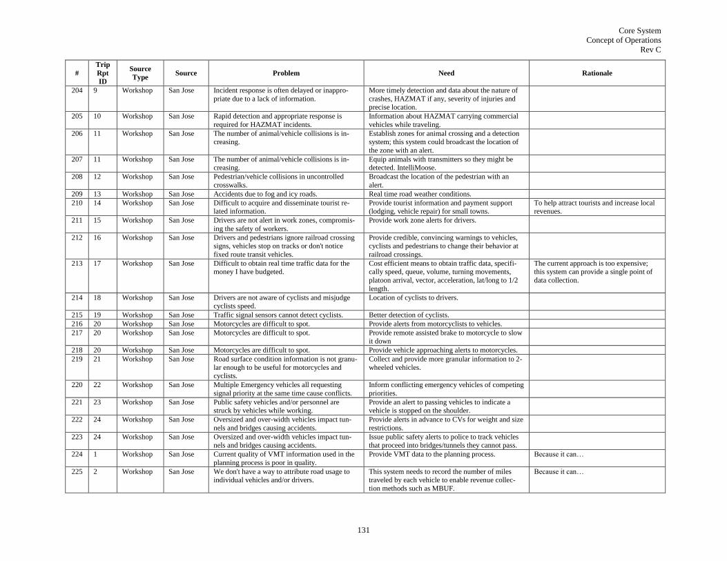
Core System
Concept of Operations
Rev C
131
#
Trip
Rpt
ID
Source
Type Source Problem Need Rationale
204 9 Workshop San Jose Incident response is often delayed or inappro-
priate due to a lack of information.
More timely detection and data about the nature of
crashes, HAZMAT if any, severity of injuries and precise location.
205 10 Workshop San Jose Rapid detection and appropriate response is
required for HAZMAT incidents.
Information about HAZMAT carrying commercial
vehicles while traveling.
206 11 Workshop San Jose The number of animal/vehicle collisions is in-creasing.
Establish zones for animal crossing and a detection system; this system could broadcast the location of
the zone with an alert.
207 11 Workshop San Jose The number of animal/vehicle collisions is in-creasing.
Equip animals with transmitters so they might be detected. IntelliMoose.
208 12 Workshop San Jose Pedestrian/vehicle collisions in uncontrolled
crosswalks.
Broadcast the location of the pedestrian with an
alert.
209 13 Workshop San Jose Accidents due to fog and icy roads. Real time road weather conditions.
210 14 Workshop San Jose Difficult to acquire and disseminate tourist re-lated information.
Provide tourist information and payment support (lodging, vehicle repair) for small towns.
To help attract tourists and increase local revenues.
211 15 Workshop San Jose Drivers are not alert in work zones, compromis-
ing the safety of workers.
Provide work zone alerts for drivers.
212 16 Workshop San Jose Drivers and pedestrians ignore railroad crossing signs, vehicles stop on tracks or don't notice
fixed route transit vehicles.
Provide credible, convincing warnings to vehicles, cyclists and pedestrians to change their behavior at
railroad crossings.
213 17 Workshop San Jose Difficult to obtain real time traffic data for the money I have budgeted.
Cost efficient means to obtain traffic data, specifi-cally speed, queue, volume, turning movements,
platoon arrival, vector, acceleration, lat/long to 1/2
length.
The current approach is too expensive; this system can provide a single point of
data collection.
214 18 Workshop San Jose Drivers are not aware of cyclists and misjudge cyclists speed.
Location of cyclists to drivers.
215 19 Workshop San Jose Traffic signal sensors cannot detect cyclists. Better detection of cyclists.
216 20 Workshop San Jose Motorcycles are difficult to spot. Provide alerts from motorcyclists to vehicles.
217 20 Workshop San Jose Motorcycles are difficult to spot. Provide remote assisted brake to motorcycle to slow it down
218 20 Workshop San Jose Motorcycles are difficult to spot. Provide vehicle approaching alerts to motorcycles.
219 21 Workshop San Jose Road surface condition information is not granu-
lar enough to be useful for motorcycles and cyclists.
Collect and provide more granular information to 2-
wheeled vehicles.
220 22 Workshop San Jose Multiple Emergency vehicles all requesting
signal priority at the same time cause conflicts.
Inform conflicting emergency vehicles of competing
priorities.
221 23 Workshop San Jose Public safety vehicles and/or personnel are struck by vehicles while working.
Provide an alert to passing vehicles to indicate a vehicle is stopped on the shoulder.
222 24 Workshop San Jose Oversized and over-width vehicles impact tun-
nels and bridges causing accidents.
Provide alerts in advance to CVs for weight and size
restrictions.
223 24 Workshop San Jose Oversized and over-width vehicles impact tun-nels and bridges causing accidents.
Issue public safety alerts to police to track vehicles that proceed into bridges/tunnels they cannot pass.
224 1 Workshop San Jose Current quality of VMT information used in the
planning process is poor in quality.
Provide VMT data to the planning process. Because it can…
225 2 Workshop San Jose We don't have a way to attribute road usage to individual vehicles and/or drivers.
This system needs to record the number of miles traveled by each vehicle to enable revenue collec-
tion methods such as MBUF.
Because it can…

Core System
Concept of Operations
Rev C
132
#
Trip
Rpt
ID
Source
Type Source Problem Need Rationale
226 3 Workshop San Jose Traffic condition information is expensive, not
ubiquitous and inaccurate.
This system needs to provide comprehensive, accu-
rate and ubiquitous traffic condition and incident information so that travelers can make informed
decisions and so that they can be satisfied that their
decisions were correct (peace of mind).
227 4 Workshop San Jose Cannot invest in this program without well de-fined interfaces.
Well defined open interfaces. Open interfaces will encourage small business.
228 6 Workshop San Jose We do not have real time dynamic maps that
capture incidents, congestion, road work etc.
Real time incident and flow data. This system can potentially deliver ubi-
quitous data.
229 7 Workshop San Jose Navigation maps don't reflect the current state of
roads while the vehicle is en-route.
A way to communicate route suggestions to specific
vehicles.
Application viability, supporting business
stability.
230 8 Workshop San Jose Exchanging information with other service pro-
viders is difficult.
This system should provide a standardized mechan-
ism to facilitate the exchange of information be-tween service providers (brokerage, data and QS
advertisement).
To facilitate the growth of the service
provider business side, particularly for small business.
231 9 Workshop San Jose Acquiring Road Operating Permit requires per-sonal presence.
Need to be able to transmit authenticated permit application so the granting agency without requiring
personal presence.
Saves time and money.
232 10 Workshop San Jose The permit process is not being followed. Need authenticated information to be transmitted to
the agency, and permits to come back to the opera-tor.
Reduces the number of scofflaws.
233 11 Workshop San Jose Lack of availability of vehicle location and per-
formance data.
This system should provide a rich set of vehicle
data.
Business application providers will devel-
op business models when they see what is available.
234 14 Workshop San Jose Transit agencies do not have accurate aggrega-
tions of traveler movements, particularly in real
time, so they cannot properly measure and re-spond to demand.
Real time accurate traveler movement information.
235 15 Workshop San Jose Toll transponders are not interoperable. Provide toll payment services. So I can get rid of all these different trans-
ponders!
236 16 Workshop San Jose Managing the logistics of toll transponders is
expensive and time consuming.
Provide a way of doing toll collection without trans-
ponders.
Relieves agencies of the need to manage
transponders, saving time and resources.
237 17 Workshop San Jose Toll account management is expensive and time
consuming.
Provide a means for third party payment mechan-
isms.
Relieves agencies of the need to manage
accounts, saving time and resources.
238 18 Workshop San Jose Toll roads see decreased usage when there are
viable alternate routes.
Provide a mechanism for the tolling agency to pro-
vide information to a specific vehicle operator.
This program could leverage the tolling
mechanism to charge for increased servic-
es, creating new business models.
239 19 Workshop San Jose Service subscribers may pay for services that are granted by local or regional ISPs, but want to get
the same services when they leave the covered
area.
A capability to obtain information regardless of location with only one subscription (e.g., as in cell
phone roaming)
This program should work as a proxy for service providers to help them do busi-
ness.
240 20 Workshop San Jose Toll operators are unable to detect violators of
HOV lanes.
Need to provide a mechanism to count vehicle oc-
cupants.
241 Workshop San Jose Lane departure warning Provide the CV with an indication of when it departs
a lane without a turn signal.
242 Workshop San Jose CVs have large blind spots that other drivers are
not always aware of.
CV broadcast its "sight envelope".
243 Workshop San Jose Broadcast weight, height to be used at bridge
environments.
CVs need to broadcast their physical characteristics.

Core System
Concept of Operations
Rev C
133
#
Trip
Rpt
ID
Source
Type Source Problem Need Rationale
244 Workshop San Jose Weight, acceleration broadcast for safety at
intersections and bridges.
CVs need to broadcast their physical characteristics.
245 Workshop San Jose Prioritize dynamic routing to favor CVs broad-casting heavy weight (full).
Provide locations of CVs to centers performing dynamic routing.
246 Workshop San Jose Provide traffic maps, particularly rural. Collect CV traffic data to generate rural traffic
maps.
247 Workshop San Jose OD of commercial vehicles for long term routing
modeling.
Collect OD of commercial vehicles.
248 Workshop San Jose Enforcing lane restrictions is manpower inten-
sive.
Provide automatic notification of trucks being in the
wrong lane; trucks need lane level absolute position-ing accuracy.
249 Workshop San Jose Roads deteriorate faster due to CV traffic. Monitor truck-miles on roadway segments. By monitoring truck mileage on roads, we
can predict when maintenance must be done on a per-lane basis.
250 Workshop San Jose Vehicle situational awareness of surroundings is
compromised by line-of-sight and unpredictable
or unsafe actions of other vehicles.
Provide the vehicle with a situational picture of
other vehicles in its vicinity.
251 Workshop San Jose Merging is complicated by line-of-sight, conges-
tion and unpredictable or unsafe actions of other
vehicles.
Provide a means for a merging vehicle to request
merge permission from vehicles on the mainline.
252 Workshop San Jose Left turns require the driver to make a quick judgment.
Provide the vehicle with the information necessary to provide advice on when NOT to take a left turn,
based on approaching vehicles.
Provide sufficient functionality to enable left turn assist (don't turn, there's a vehicle
coming)
253 Workshop San Jose Provide means for tracking vehicles that are violat-ing the law.
254 Workshop San Jose Provide means to enforce speed limits automatical-
ly.
Free up police to pursue other higher
priority activities.
255 Workshop San Jose Drivers don't always realize when they are vi-olating the speed limit.
Provide means to alert a driver when her vehicle is violating the speed limit.
256 Workshop San Jose Detecting unsafe conditions across all roads is
difficult.
Provide vehicle performance and sensory data to a
long term archive.
Analysis of historical vehicle data can
yield understanding of unsafe roads.
257 Workshop San Jose Determining road network performance requires access to data that is not typically captured to-
day.
Provide road network performance data to a long term archive.
Analysis of historical road network per-formance data will improve understanding
of road network performance
258 Workshop San Jose Determining the real-time "state of the road" requires the collection of data beyond the scope
of today's sensory infrastructure in most areas.
Collect information from vehicles that can be used to produce traveler information.
259 Workshop San Jose Determining optimal pricing for HOT lanes
requires accurate real time traffic data.
Provide speed and road lane location information to
aid in determining optimal pricing for HOT lanes.
260 Workshop San Jose Use queue lengths as key input to allocating
resources to manage traffic.
Monitor queue lengths.
261 Workshop San Jose Safety and mobility. Use information to predict local trajectories.
262 Workshop San Jose To assist with traffic and incident management. Detect incidents.
263 Workshop San Jose To enable HOT, better traffic management, incident detection and incident management.
Must provide lane level positioning accuracy.
264 Workshop San Jose Identifying locations, severity of potholes in time
consuming and riddled with errors from inaccu-rate citizen reports.
Provide vehicle accelerometer data to maintenance
centers.
Analysis of accelerometer data will lead to
automated detection of potholes which will increase maintenance efficiency.
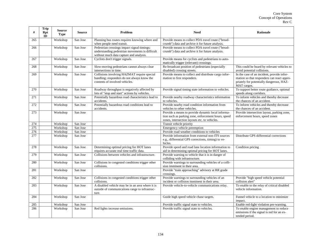
Core System
Concept of Operations
Rev C
134
#
Trip
Rpt
ID
Source
Type Source Problem Need Rationale
265 Workshop San Jose Planning bus routes requires knowing where and
when people need transit.
Provide means to collect PDA travel route ("bread-
crumb") data and archive it for future analysis.
266 Workshop San Jose Pedestrian crossings impact signal timings; understanding pedestrian movements is difficult
without much data capture and analysis.
Provide means to collect PDA travel route ("bread-crumb") data and archive it for future analysis.
267 Workshop San Jose Cyclists don't trigger signals. Provide means for cyclists and pedestrians to auto-matically trigger (relevant) crossings.
268 Workshop San Jose Slow-moving pedestrians cannot always clear
intersections in time.
Re-broadcast position of pedestrians (especially
disabled) crossing streets.
This could be heard by relevant vehicles to
avoid potential collisions.
269 Workshop San Jose Collisions involving HAZMAT require special handling; responders do not always know the
contents of involved vehicles.
Provide means to collect and distribute cargo infor-mation to first responders.
In the case of an incident, provide infor-mation so that responders can react appro-
priately for potentially dangerous, HAZ-
MAT cargos.
270 Workshop San Jose Roadway throughput is negatively affected by
lots of "stop and start" actions by vehicles.
Provide signal timing state information to vehicles. To support better route guidance, optimal
speeds along corridors.
271 Workshop San Jose Potentially hazardous road characteristics lead to
accidents.
Provide nearby roadway characteristics information
to vehicles.
To inform vehicles and thereby decrease
the chances of an accident.
272 Workshop San Jose Potentially hazardous road conditions lead to
accidents.
Provide nearby road condition information from
vehicles to other vehicles.
To inform vehicles and thereby decrease
the chances of an accident.
273 Workshop San Jose Provide a means to provide dynamic local informa-
tion such as parking zone, enforcement hours, speed zones, intersection layouts etc. to vehicles.
Provide intersection layout, parking zone,
enforcement hours, speed zones
274 Workshop San Jose Transit vehicle priority
275 Workshop San Jose Emergency vehicle preemption
276 Workshop San Jose Provide road weather conditions to vehicles
277 Workshop San Jose Provide information from external non-ITS sources e.g., differential GPS corrections, timing) to ve-
hicles.
Distribute GPS differential corrections
278 Workshop San Jose Determining optimal pricing for HOT lanes requires accurate real time traffic data.
Provide speed and road lane location information to aid in determining optimal pricing for HOT lanes.
Condition pricing
279 Workshop San Jose Collisions between vehicles and infrastructure. Provide warning to vehicle that it is in danger of
colliding with infrastructure.
280 Workshop San Jose Collisions in congested conditions trigger other collisions.
Provide warnings to surrounding vehicles of a colli-sion imminent in their area.
281 Workshop San Jose Provide "train approaching" advisory at RR grade
crossings.
282 Workshop San Jose Collisions in congested conditions trigger other collisions.
Provide warnings to surrounding vehicles of an incident or collision imminent in their area.
Provide "high speed vehicle potential collision alert"
283 Workshop San Jose A disabled vehicle may be in an area where it is
outside of communications range to infrastruc-ture.
Provide vehicle-to-vehicle communications relay. To enable to the relay of critical disabled
vehicle information.
284 Workshop San Jose Guide high speed vehicle chase targets. Funnel vehicle to a location to minimize
impact.
285 Workshop San Jose Provide traffic signal state to vehicles. Enable red-light violation pre-warning.
286 Workshop San Jose Red lights increase emissions. Provide traffic signal state to vehicles. To enable engine management to reduce emissions if the signal is red for an ex-
tended period.

Core System
Concept of Operations
Rev C
135
#
Trip
Rpt
ID
Source
Type Source Problem Need Rationale
287 Workshop San Jose Collect time and location of intersection violations
and provide to archive for later analysis.
Use data on intersection violations to
support cost benefit analysis of adding equipment to that intersection.
288 Workshop San Jose Provide physical restriction information (height,
weight, HAZMAT, etc.) to vehicles prior to final
decision point.
Identify weight, height and width restric-
tions on tunnels and bridges.
289 Workshop San Jose Provide parking space availability and location to
vehicles in advance of their arrival.
Safety and mobility improvements as
drivers avoid frustration; also incentivize
mode shifting.
290 Workshop San Jose Broadcast the number of seats available on transit
vehicles to vehicles approaching a mode shift deci-
sion point.
Incentivize mode shifts
291 Workshop San Jose Various commercial broadcasts Advertising
292 Workshop San Jose Traveler information broadcasts - travel time for
various modes.
To enable informed decision making.
293 Workshop San Jose Provide means to communicate back to pedestrians. To notify of walkway closures, escalators
and the like.
294 Workshop San Jose Provide an advertising mechanism
295 Workshop San Jose There is insufficient vehicle usage information to
help vehicle manufacturers profile and target
their vehicle users.
Provide a means for vehicle manufacturers to gain
information on how the vehicle is being used.
Vehicle manufacturers: Aggregate driver
behavior information, profile users and
target marketing.
296 Workshop San Jose There is insufficient vehicle usage information to
help insurance companies to profile and target
their vehicle users.
Provide a means for insurance companies to gain
information on how the vehicle is being used.
Insurance companies: Aggregate driver
behavior information for insurance pur-
poses
297 Workshop San Jose There is currently no means to determine the number of occupants in a vehicle
Provide a means to detect the number of vehicle occupants
In support of roadway planning
298 Workshop San Jose There is no way to monitor safe transit vehicle
operator behavior
Provide monitoring information regarding unsafe
transit vehicle operators behavior
Record and monitor transit vehicle opera-
tor behavior
299 Workshop San Jose There is no way to monitor transit vehicle opera-tor behavior for training purposes
Provide monitoring information regarding transit vehicle operators behavior for training purposes
Training assistance for transit operators in training
300 Workshop San Jose Remote physical monitoring of transit vehicles
requires motion video transmission, requiring bandwidth not available with current transit
systems.
Provide means for getting video from transit/fleet
vehicles back to operations center.
Upon detection of a dangerous situation,
activate camera.
301 Workshop San Jose There currently is no way to monitor and trans-mit transit parking information
Provide a means to determine transit vehicle parking availability
Monitor transit capacity
302 Workshop San Jose There currently is no way to monitor and trans-
mit transit vehicle health
Provide a means to monitor and transmit transit
vehicle health
Monitor transit vehicle health
303 Workshop San Jose There could be a more comprehensive way to perform wireless roadside inspections and WIM
Provide a means to collect wireless comprehensive roadside inspection information including WIM
Wireless roadside inspection/WIM
304 Workshop San Jose There could be a more comprehensive way to
perform commercial vehicle driver credential
screening
Provide a means to collect wireless comprehensive
commercial vehicle driver credential information
Driver Credential screening
305 Workshop San Jose Mobile inspection
306 Workshop San Jose There could be a more comprehensive way to
perform commercial vehicle carrier screening
Provide a means to collect wireless comprehensive
commercial vehicle carrier information
Provide carrier/drive info about their
vehicles
307 Workshop San Jose Driver distraction is a leading cause of accidents. Provide some means for detecting distracted drivers. Detect and avoid driver distraction
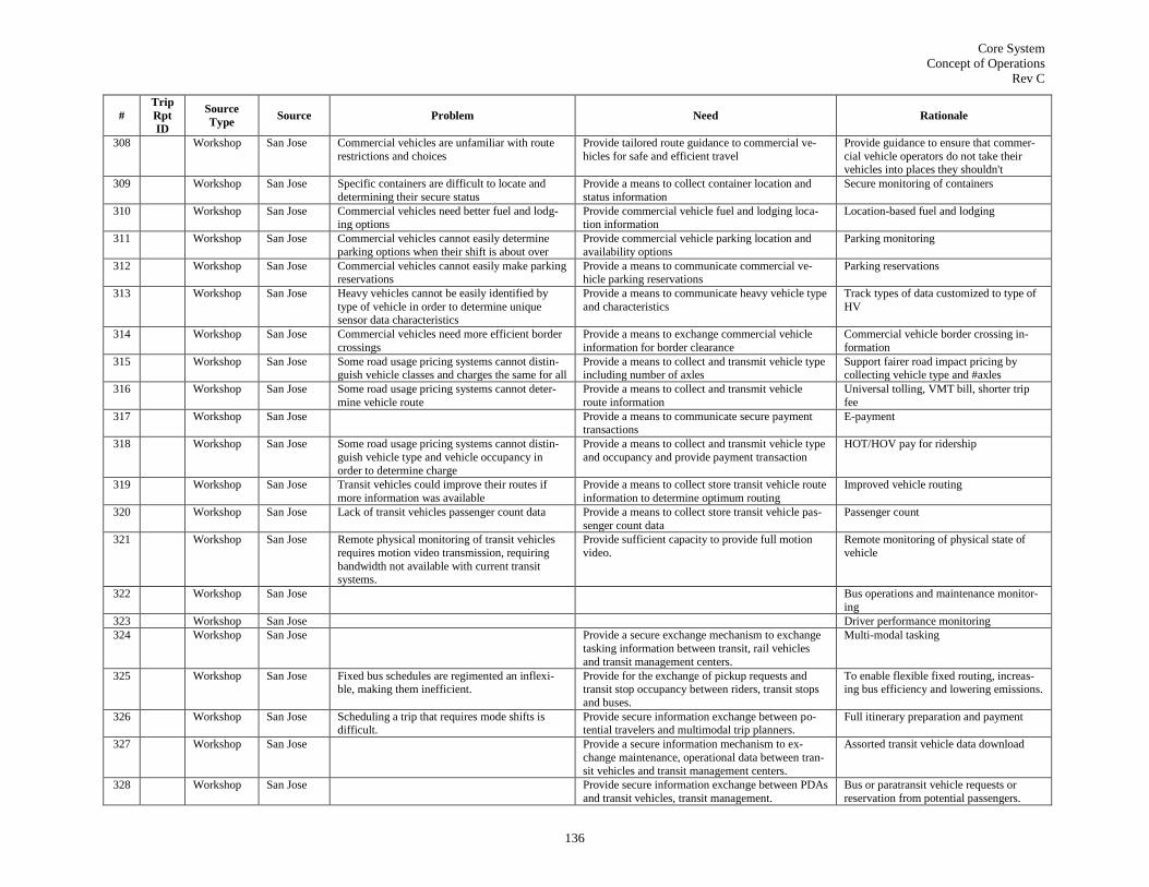
Core System
Concept of Operations
Rev C
136
#
Trip
Rpt
ID
Source
Type Source Problem Need Rationale
308 Workshop San Jose Commercial vehicles are unfamiliar with route
restrictions and choices
Provide tailored route guidance to commercial ve-
hicles for safe and efficient travel
Provide guidance to ensure that commer-
cial vehicle operators do not take their vehicles into places they shouldn't
309 Workshop San Jose Specific containers are difficult to locate and
determining their secure status
Provide a means to collect container location and
status information
Secure monitoring of containers
310 Workshop San Jose Commercial vehicles need better fuel and lodg-ing options
Provide commercial vehicle fuel and lodging loca-tion information
Location-based fuel and lodging
311 Workshop San Jose Commercial vehicles cannot easily determine
parking options when their shift is about over
Provide commercial vehicle parking location and
availability options
Parking monitoring
312 Workshop San Jose Commercial vehicles cannot easily make parking reservations
Provide a means to communicate commercial ve-hicle parking reservations
Parking reservations
313 Workshop San Jose Heavy vehicles cannot be easily identified by
type of vehicle in order to determine unique sensor data characteristics
Provide a means to communicate heavy vehicle type
and characteristics
Track types of data customized to type of
HV
314 Workshop San Jose Commercial vehicles need more efficient border
crossings
Provide a means to exchange commercial vehicle
information for border clearance
Commercial vehicle border crossing in-
formation
315 Workshop San Jose Some road usage pricing systems cannot distin-guish vehicle classes and charges the same for all
Provide a means to collect and transmit vehicle type including number of axles
Support fairer road impact pricing by collecting vehicle type and #axles
316 Workshop San Jose Some road usage pricing systems cannot deter-
mine vehicle route
Provide a means to collect and transmit vehicle
route information
Universal tolling, VMT bill, shorter trip
fee
317 Workshop San Jose Provide a means to communicate secure payment transactions
E-payment
318 Workshop San Jose Some road usage pricing systems cannot distin-
guish vehicle type and vehicle occupancy in
order to determine charge
Provide a means to collect and transmit vehicle type
and occupancy and provide payment transaction
HOT/HOV pay for ridership
319 Workshop San Jose Transit vehicles could improve their routes if
more information was available
Provide a means to collect store transit vehicle route
information to determine optimum routing
Improved vehicle routing
320 Workshop San Jose Lack of transit vehicles passenger count data Provide a means to collect store transit vehicle pas-
senger count data
Passenger count
321 Workshop San Jose Remote physical monitoring of transit vehicles
requires motion video transmission, requiring
bandwidth not available with current transit systems.
Provide sufficient capacity to provide full motion
video.
Remote monitoring of physical state of
vehicle
322 Workshop San Jose Bus operations and maintenance monitor-
ing
323 Workshop San Jose Driver performance monitoring
324 Workshop San Jose Provide a secure exchange mechanism to exchange
tasking information between transit, rail vehicles
and transit management centers.
Multi-modal tasking
325 Workshop San Jose Fixed bus schedules are regimented an inflexi-ble, making them inefficient.
Provide for the exchange of pickup requests and transit stop occupancy between riders, transit stops
and buses.
To enable flexible fixed routing, increas-ing bus efficiency and lowering emissions.
326 Workshop San Jose Scheduling a trip that requires mode shifts is difficult.
Provide secure information exchange between po-tential travelers and multimodal trip planners.
Full itinerary preparation and payment
327 Workshop San Jose Provide a secure information mechanism to ex-
change maintenance, operational data between tran-
sit vehicles and transit management centers.
Assorted transit vehicle data download
328 Workshop San Jose Provide secure information exchange between PDAs
and transit vehicles, transit management.
Bus or paratransit vehicle requests or
reservation from potential passengers.

Core System
Concept of Operations
Rev C
137
#
Trip
Rpt
ID
Source
Type Source Problem Need Rationale
329 Workshop San Jose Paying for transit fair slows bus loading. Provide means to facilitate payments for transit
vehicle riders.
Reducing payment time will decrease
loading time which will increase net pas-senger throughput.
330 Workshop San Jose The services we want to provide require constant
connectivity.
Ubiquitous communications coverage
331 Workshop San Jose Provide for a secure exchange of information be-tween a CV and freight management.
For reload requests, to reduce deadhead-ing.
332 Workshop San Jose Parking reservations
333 Workshop San Jose HV mechanical failures can take a long time to
properly respond to.
Communications (not necessarily high speed) over
all CV routes.
Knowing details about a vehicle failure
will enable more efficient dispatch of repair vehicles.
334 Workshop San Jose Permit process takes trucks out of service and
puts them in line.
Permit granting and revocation
335 Workshop San Jose Vehicles don't yield to pedestrians in crosswalks. Provide a means for identifying offending vehicles. This information could be used in [puni-tive or informative] ways to improve
pedestrian safety.
336 Workshop San Jose Pedestrians and vehicles interact often, and inat-tentive pedestrians or vehicle operators may
collide.
Provide collision alerts to pedestrians of vehicles that may hit them.
337 Workshop San Jose Bike-specific features such as stands, parking
areas and blockages are not monitored by tradi-tional traffic monitoring.
Provide a means for cyclists to provide bike path
information to service providers.
Allowing cyclists to identify bike stands,
parking areas, blockages.
338 Workshop San Jose Bike paths are "captive" routes, and an incident
blocking the path may cause a severe disruption for cyclists.
Provide for the exchange of bike path incident in-
formation between service providers and cyclists.
Incident notification on bike paths
339 Workshop San Jose Mode shifting and slugging require coordination
between traveler and 3rd parties that is not well
facilitated today.
Provide for the exchange of ride sharing and mode
shift information between travelers and ISPs, transit
centers.
multi-modal and mode shifting assistance
(slugging)
340 Workshop San Jose Internet services are required to access some
services.
Provide access to Internet services. Surf the web, read e-mail etc.
341 Workshop San Jose Ride sharing absent trust between participants
would benefit from independent assessment of the character of participating individuals.
Provide secure transactional links between prospec-
tive ride-sharers and 3rd party verification provid-ers.
342 Workshop San Jose Bike parking locations are not well marked,
resulting in cyclists searching for places to se-curely store their vehicle.
Provide information exchange between data stores
that identify bike storage locations and risk and cyclists.
Bike rack location and risk
343 Workshop San Jose Bike-route selection should take into account
different factors than vehicle route selection.
Provide information exchange between route pro-
viders and cyclists.
Bike-specific navigation
344 Workshop San Jose Cyclists are affected by signals to a more signifi-cant degree than vehicles, being unable to trigger
actuation and still having to abide by rules, and
being more incentivized to maintain a constant
speed.
Provide the real-time status of signal timings to cyclists in the area.
Signal timing status to help cyclists choose routes
345 Workshop San Jose Large groups of cyclists have different perfor-
mance characteristics than similar groups of vehicles, but have to follow the same signaliza-
tion rules.
Provide signal preemption, priority and dynamic
retiming support for signals seeing a high concentra-tion of cyclists
346 Workshop San Jose Remote request for ped signals

Core System
Concept of Operations
Rev C
138
#
Trip
Rpt
ID
Source
Type Source Problem Need Rationale
347 Workshop San Jose Signals operate on static or actuated patterns that
do not respond well to dynamic conditions, increasing congestion.
Provide more advanced (upstream) traffic condition
information to signals to enable dynamic signal control.
348 Workshop San Jose Transportation charges are small fees often paid
by cash or change, which require physical ex-
change, slowing down traffic.
Facilitate the exchange of information to support
micropayments.
349 Workshop San Jose Different systems may use different communica-
tions media for the same application.
Coordinate the exchange of information between
various communications mechanisms (3G, DSRC
etc.)
350 Document Final Re-
port: VII
POC Tech Desc - Veh
Provide for infrastructure initiated safety applica-
tions
VII Viability Criteria
351 Document Final Re-
port: VII
POC Tech Desc - Veh
Support vehicle initiated safety applications VII Viability Criteria
352 Document Final Re-
port: VII
POC Tech
Desc - Veh
Provide for collection of various mobility data from
vehicles
VII Viability Criteria
353 Document Final Re-
port: VII POC Tech
Desc - Veh
Provide for use of collected mobility data by state
and local authorities
VII Viability Criteria
354 Document Final Re-port: VII
POC Tech
Desc - Veh
Exhibit sufficient benefit in terms of road and traffic management and transportation efficiency
VII Viability Criteria
355 Document Final Re-port: VII
POC Tech
Desc - Veh
Vehicles can access private services through the system
VII Viability Criteria
356 Document Final Re-
port: VII
POC Tech Desc - Veh
Private services can access vehicles through the
system
VII Viability Criteria
357 Document Final Re-
port: VII POC Tech
Desc - Veh
Co-existence of private services with safety and
mobility services is economically viable
VII Viability Criteria
358 Document Final Re-
port: VII
POC Tech
Desc - Veh
Private services can be implemented in a manner
that does not interfere with safety and mobility
applications
VII Viability Criteria
359 Document Final Re-port: VII
POC Tech
Desc - Veh
System is resistant to denial of service, replay and intrusion attacks
VII Viability Criteria

Core System
Concept of Operations
Rev C
139
#
Trip
Rpt
ID
Source
Type Source Problem Need Rationale
360 Document Final Re-
port: VII POC Tech
Desc - Veh
Security compromises can be identified and miti-
gated
VII Viability Criteria
361 Document Final Re-
port: VII POC Tech
Desc - Veh
Security credentials can be properly distributed and
managed at all levels of deployment
VII Viability Criteria
362 Document Final Re-port: VII
POC Tech
Desc - Veh
Roadside Equipment software can be remotely managed through the network
VII Viability Criteria
363 Document Final Re-
port: VII
POC Tech Desc - Veh
VII-related vehicle software can be securely main-
tained over the vehicle life cycle
VII Viability Criteria
364 Document Final Re-
port: VII
POC Tech
Desc - Veh
Cannot track and individual vehicle over any road
segment longer than 2 km
VII Viability Criteria
365 Document Final Re-
port: VII POC Tech
Desc - Veh
Cannot identify any individual vehicle as violating a
traffic law through publicly collected data
VII Viability Criteria
366 Document Final Re-
port: VII POC Tech
Desc - Veh
Cannot identify a vehicle or vehicle occupant or
owner from messages sent to, or through, the infra-structure
VII Viability Criteria
367 1-on-1 Owosso Tour
Data should not be used for law enforcement. Hearsay: "Owosso citizens"
368 1-on-1 Owosso
Tour
Anonymity is preserved
369 1-on-1 Owosso Tour
Younger citizens do not care about anonymity
370 1-on-1 Owosso
Tour
Need to pre-empt traffic signals to enable better
traffic flow
371 1-on-1 Owosso Tour
Need to provide a mechanism to record vehicle miles in support of mileage-based user fees
372 1-on-1 Owosso
Tour
This system should be built by people local to its
deployment.
373 1-on-1 Owosso Tour
This system should provide benefit to safety and mobility at intersections without requiring new
signal controllers
374 1-on-1 Owosso Tour
Mobility improvements must be sufficient that users are willing to pay for them.
375 1-on-1 VIIC The Vehicle must not be inside the System
376 1-on-1 VII
Testbed
The maintenance concept should not require taking
infrastructure out of service for extensive periods.

Core System
Concept of Operations
Rev C
140
#
Trip
Rpt
ID
Source
Type Source Problem Need Rationale
377 1-on-1 VII
Testbed, BAH meet-
ing, Noblis
Security Briefing
Security must be integral to the system concept
378 1-on-1 VII
Testbed
The maintenance concept should not require more
personnel than …. WHAT?
379 Document VII Con-Ops V1.2
Need to improve vehicle safety margins.
380 Document VII Con-
Ops V1.2
Support V2V safety applications
381 Document VII Con-Ops V1.2
Provide communications from DHS (FEMA) to drivers in case of natural disasters and security
incidents.
382 Document VII Con-Ops V1.2
Provide comprehensive traffic flow information to TMCs to enable global optimization of traffic flow.
383 Document VII Con-
Ops V1.2
Provide comprehensive weather information to
TMCs to enable global optimization of traffic flow.
384 Document VII Con-Ops V1.2
Provide communications from vehicle to infrastruc-ture necessary to process toll payments, enabling
over-the-road tolling, congestion pricing, high-
occupancy tolling
385 Document VII Con-Ops V1.2
Provide information and communications necessary to support localized safety improvements
386 Document VII Con-
Ops V1.2
Provide means for pre-empting signals for qualified
vehicles.
387 Document VII Con-Ops V1.2
Provide means for prioritizing different vehicles at traffic signals.
388 Document VII Con-
Ops V1.2
Provide means for monitoring physical state of
roadways.
389 Document VII Con-Ops V1.2
Provide increased traffic information to support the planning process.
390 Document VII Con-
Ops V1.2
Provide tracking of transit vehicles.
391 Document VII Con-
Ops V1.2
Provide mechanism for monitoring maintenance
health of transit vehicles.
392 Document VII Con-
Ops V1.2
Provide mechanism to improve safety and security
of transit customers.
393 Document VII Con-
Ops V1.2
Monitor transit vehicles and provide timely arrival
information.
394 Document VII Con-
Ops V1.2
Monitor transit usage patterns to enable better ser-
vice planning.
395 Document VII Con-
Ops V1.2
Provide emergency information to PSAPs in case of
emergency to enable more timely emergency re-
sponse.
396 Document VII Con-Ops V1.2
Provide information to support air quality analysis, chiefly to MPOs.
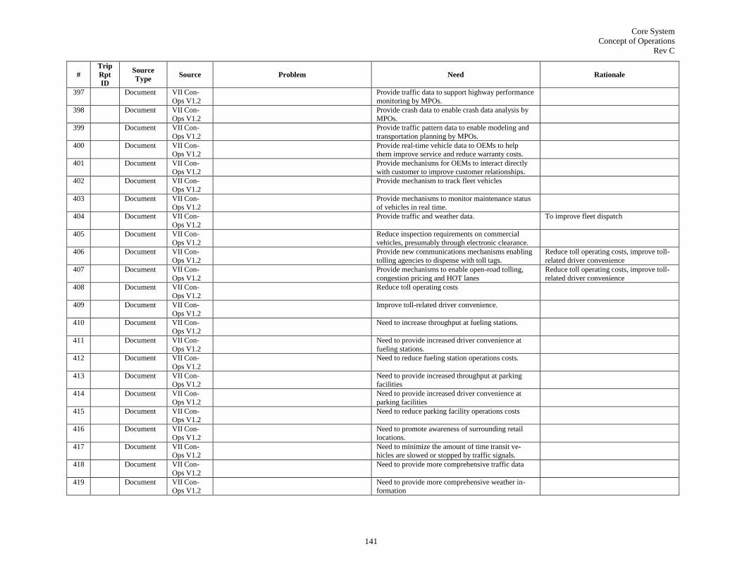
Core System
Concept of Operations
Rev C
141
#
Trip
Rpt
ID
Source
Type Source Problem Need Rationale
397 Document VII Con-
Ops V1.2
Provide traffic data to support highway performance
monitoring by MPOs.
398 Document VII Con-Ops V1.2
Provide crash data to enable crash data analysis by MPOs.
399 Document VII Con-
Ops V1.2
Provide traffic pattern data to enable modeling and
transportation planning by MPOs.
400 Document VII Con-
Ops V1.2
Provide real-time vehicle data to OEMs to help
them improve service and reduce warranty costs.
401 Document VII Con-
Ops V1.2
Provide mechanisms for OEMs to interact directly
with customer to improve customer relationships.
402 Document VII Con-
Ops V1.2
Provide mechanism to track fleet vehicles
403 Document VII Con-
Ops V1.2
Provide mechanisms to monitor maintenance status
of vehicles in real time.
404 Document VII Con-
Ops V1.2
Provide traffic and weather data. To improve fleet dispatch
405 Document VII Con-
Ops V1.2
Reduce inspection requirements on commercial
vehicles, presumably through electronic clearance.
406 Document VII Con-
Ops V1.2
Provide new communications mechanisms enabling
tolling agencies to dispense with toll tags.
Reduce toll operating costs, improve toll-
related driver convenience
407 Document VII Con-
Ops V1.2
Provide mechanisms to enable open-road tolling,
congestion pricing and HOT lanes
Reduce toll operating costs, improve toll-
related driver convenience
408 Document VII Con-
Ops V1.2
Reduce toll operating costs
409 Document VII Con-
Ops V1.2
Improve toll-related driver convenience.
410 Document VII Con-
Ops V1.2
Need to increase throughput at fueling stations.
411 Document VII Con-
Ops V1.2
Need to provide increased driver convenience at
fueling stations.
412 Document VII Con-
Ops V1.2
Need to reduce fueling station operations costs.
413 Document VII Con-Ops V1.2
Need to provide increased throughput at parking facilities
414 Document VII Con-
Ops V1.2
Need to provide increased driver convenience at
parking facilities
415 Document VII Con-Ops V1.2
Need to reduce parking facility operations costs
416 Document VII Con-
Ops V1.2
Need to promote awareness of surrounding retail
locations.
417 Document VII Con-Ops V1.2
Need to minimize the amount of time transit ve-hicles are slowed or stopped by traffic signals.
418 Document VII Con-
Ops V1.2
Need to provide more comprehensive traffic data
419 Document VII Con-Ops V1.2
Need to provide more comprehensive weather in-formation

Core System
Concept of Operations
Rev C
142
#
Trip
Rpt
ID
Source
Type Source Problem Need Rationale
420 Document Principles
for this DOT Pro-
gram
Must not compromise safety
421 Document Principles
for this DOT Pro-
gram
Must not compromise security
422 Document Principles for this
DOT Pro-
gram
Must protect privacy
423 Document VII Day 1
Use Cases
Need to provide traveler information customized to
the real-time performance of a traveler's journey.
424 Document VII Day 1
Use Cases
Need to enable the dynamic modification of ramp
metering rates in response to traffic conditions.
425 Document VII Day 1
Use Cases
Need to improve throughput of signalized intersec-
tions.
426 Document VII Day 1
Use Cases
Need to improve the accuracy of, and reduce the
information gathering costs of the planning process.
427 Document VII Day 1
Use Cases
Need to improve the distribution of vehicles among
parallel routes.
428 Document VII Day 1
Use Cases
Need to improve detection of weather-impacted
road conditions.
429 Document VII Day 1
Use Cases
Need to improve resolution and characterization of
treatments on roadways.
430 Document VII Day 1
Use Cases
Need to improve detection of physical conditions of
roadways (potholes, cracked pavement, etc.).
431 Document VII Day 1
Use Cases
Need to provide relevant road weather condition
information to travelers.
432 Document VII Day 1
Use Cases
Need to improve granularity, precision and accuracy
of road weather conditions.
433 Document VII Day 1
Use Cases
Need to support fixed fee tolls.
434 Document VII Day 1 Use Cases
Need to support variable fee tolls based on distance traveled.
435 Document VII Day 1
Use Cases
Need to support service-based tolls such as HOT
lanes
436 Document Final Re-port - VII
POC Vol
2b - Infra
Need to provide broadcast messages from back office facilities to automobiles in specific geograph-
ic areas.
437 Document Final Re-port - VII
POC Vol
2b - Infra
Need to provide broadcast messages from roadside infrastructure to automobiles.

Core System
Concept of Operations
Rev C
143
#
Trip
Rpt
ID
Source
Type Source Problem Need Rationale
438 Document Final Re-
port - VII POC Vol
2b - Infra
Need to provide broadcast messages between auto-
mobiles.
439 Document Final Re-
port - VII POC Vol
2b - Infra
Need to distribute topical information from automo-
biles to back office users.
440 Document Final Re-port - VII
POC Vol
2b - Infra
Need to assure anonymity of users when those users use services not requiring individual identification
441 Document Final Re-
port - VII
POC Vol 2b - Infra
Need to provide opaque transmission of sensitive
data through the system, such that transmitter and
end receiver can read information, but no place in between can.
442 Document Final Re-
port - VII
POC Vol
2b - Infra
Need to ensure the authenticity of transmitted mes-
sages.
443 Document Final Re-
port - VII POC Vol
2b - Infra
Need to be resistant to denial-of-service attacks Doesn't call out DoS here, but it is men-
tioned elsewhere
444 Document Final Re-
port - VII POC Vol
2b - Infra
Need to be able to identify and terminate a severe
attack on the system.
445 Document VII POC Apps Con-
Ops V1.4
Need to provide road and traffic condition informa-tion (including travel times, incidents, road closures,
work zones) that may affect trips to travelers.
446 Document VII POC
Apps Con-Ops V1.4
Need to provide mechanisms enabling vehicles to
present locally relevant signage and legal informa-tion to vehicle drivers and occupants.
447 Document VII POC
Apps Con-Ops V1.4
Need to provide routing directions to vehicle opera-
tors, with routes distributing traffic to provide best use of the roadway network.
448 Document VII POC
Apps Con-Ops V1.4
Need to provide mechanisms for paying for parking
depending on vehicle location and vehicle type.
449 Document VII POC
Apps Con-
Ops V1.4
Need to provide mechanism to pay for gasoline
depending on vehicle location and fuel type.
450 Document VII POC
Apps Con-
Ops V1.4
Need to provide mechanisms to pay roadway tolls
depending on vehicle location (by lane) and vehicle
type.

Core System
Concept of Operations
Rev C
144
#
Trip
Rpt
ID
Source
Type Source Problem Need Rationale
451 Document VII POC
Apps Con-Ops V1.4
Need to measure the effectiveness of signal systems
(possibly by measuring queue length, stop locations, stop delay, cycle failures, time and position trajecto-
ries, queue overflows, arterial travel time).
452 Document VII POC
Apps Con-Ops V1.4
Need to collect the data necessary to improve signal
performance (possibly including volumes by lane, turning movements, stops and stop locations, stop
delay)
453 Document VII POC Apps Con-
Ops V1.4
Need to provide the measures necessary to deter-mine the effectiveness of ramp metering systems
(possibly including:
link travel times on adjoining freeways, mainline speed by lane, ramp queue
length, delay on ramps and mainline,
queue spillback, stops and stop locations on ramps and mainline, stop delay on
ramps and mainline, time in queue)
454 Document VII POC Apps Con-
Ops V1.4
Need to help generate new ramp meter rates (possi-bly by providing the following measures:
link travel times on adjoining freeways, mainline speed by lane, ramp queue
length, queue spillback, stops and stop
locations on ramps and mainline, stop delay on ramps and mainline, time in
queue)
455 Document VII POC
Apps Con-Ops V1.4
Need to efficiently determine the location and sever-
ity of potholes
456 Document VII POC
Apps Con-Ops V1.4
Need to determine ground-level atmospheric condi-
tions
457 Document VII POC
Apps Con-
Ops V1.4
Need to determine pavement surface conditions,
including slickness and moisture covering.
458 Document VII POC
Apps Con-
Ops V1.4
Need to provide locally relevant weather advisories
to vehicle drivers and occupants
459 Document VII POC Apps Con-
Ops V1.4
Need to provide the measures necessary to evaluate road network performance (possibly including travel
times, volumes, trip paths).
460 Document VII POC Apps Con-
Ops V1.4
Need to help balance the traffic load amongst corri-dor assets (possibly by providing the following
measures:
travel times by link on freeways and arte-rials, speed profiles by lane on freeways
and arterials, volumes on freeways and
arterials, stop locations on freeways and arterials, stop delay on freeways and arte-
rials, lane closures on freeways and arte-
rials.
461 Document VII POC
Apps Con-
Ops V1.4
Need to send high-priority messages from one ve-
hicle to another vehicle in a timely fashion (for
example, "I'm slamming on the brakes now!" to vehicles in the immediate rear of the speaking ve-
hicle)

Core System
Concept of Operations
Rev C
145
#
Trip
Rpt
ID
Source
Type Source Problem Need Rationale
462 Document VII POC
Apps Con-Ops V1.4
Need to warn vehicle operators of an impending
violation of a traffic signal.
463 Document VII POC
Apps Con-
Ops V1.4
Need to warn vehicle operators of an impending
violation of an unsignalized intersection.
464 Document VII POC
Apps Con-
Ops V1.4
Need to warn vehicle operators of a potential safety
event (lane departure, rollover) due to a combination
of vehicle speed and roadway geometry.
465 Document Final Re-
port - VII
POC Vol 3b
Need to protect against malicious intrusion
466 Document Final Re-
port - VII
POC Vol 3b
Need to ensure the anonymity of users
467 Document Final Re-
port - VII
POC Vol
3b
Need to maintain the privacy of users
468 Document Final Re-
port - VII POC Vol
3b
Need to provide anonymous probe data from ve-
hicles to data consumers
469 Document Final Re-port - VII
POC Vol
3b
Need to provide TOC advisory messages to vehicles in targeted geographic locations
470 Document Final Re-port - VII
POC Vol
3b
Need to provide communications between vehicles and remote network servers (TOCs)
471 Document Final Re-
port - VII
POC Vol 3b
Need to provide communications between signal
controllers and vehicles
472 Document Final Re-
port - VII POC Vol
3b
Need to provide communications between signal
controllers and remote network servers (TOCs)
473 Document Final Re-
port - VII
POC Vol
3b
Need to provide authentication of messages ex-
changed between vehicles and signal controllers
474 Document Final Re-port - VII
POC Vol
3b
Need to provide authentication of messages ex-changed between vehicles and remote network
servers

Core System
Concept of Operations
Rev C
146
#
Trip
Rpt
ID
Source
Type Source Problem Need Rationale
475 Document Final Re-
port - VII POC Vol
3b
Need to provide authentication of messages ex-
changed between vehicles
476 Document Final Re-
port - VII POC Vol
3b
Need to provide heartbeat messages to enable safety
applications by improving situational awareness between vehicles
477 Document Final Re-port - VII
POC Vol
3b
Need to generate and distribute localized micro maps containing detailed roadway geometries for
intersections and roadway segments.
478 Document Final Re-
port - VII
POC Vol 3b
Need to provide position correction data to vehicles
479 Document Final Re-
port - VII
POC Vol
3b
Need to remotely provision and manage roadside
equipment from a central platform
480 1-on-1 AERIS Monitor auto exhaust at all times, particularly on
Code Red Days
481 1-on-1 CVO Heavy vehicle needs to share its characteristics with the roadside.
482 1-on-1 CVO Roadside needs to share heavy vehicle characteris-
tics with centers.
483 1-on-1 CVO Trucks need to be interoperable with other vehicles
484 1-on-1 Policy Privacy framework needs to be preserved 2 OEMs will walk away if it isn't
485 1-on-1 Standards V2V needs to supplement infrastructure. Provide increased range in areas of low
deployment
486 1-on-1 Transit Transit vehicles need more communications band-
width than they have today.
487 1-on-1 Transit Transit vehicles need reduced communications
latency versus what they have today.
488 1-on-1 Transit Transit vehicles need operator-initiated video trans-mission from bus to center.
To support safety and protect against litigation.
489 1-on-1 Transit Needs the ability to know how many passengers are
on each bus, both at the bus and the center.
490 1-on-1 Transit Real-time bus fare transactions.
491 1-on-1 Transit Need the ability to provide bus operational characte-
ristics (health, emissions) to the center.
492 1-on-1 Transit Provide transit information, such as available ser-
vices, bike rack and disabled equipment status, to travelers in real time
493 1-on-1 Transit Provide a means to tell cyclists when a bus is near-
by.
494 1-on-1 Transit Provide a means to tell pedestrians when a bus is nearby.

Core System
Concept of Operations
Rev C
147
#
Trip
Rpt
ID
Source
Type Source Problem Need Rationale
495 1-on-1 Transit Paratransit needs to be able to have guaranteed real-
time communication of route and person to pick up.
In case of emergency evocation for people
with special needs.
496 1-on-1 Weather Centers need to obtain road surface conditions that affect vehicle safety.
497 1-on-1 Weather Provide the facilities to enable weather-responsive
traffic management strategies
498 1-on-1 Weather Get weather data into traffic signal controllers
499 Workshop DC How to get municipalities on board? Municipali-
ties own equipment and right of way over dep-
loyed equipment. Mayor controls when lights turn red/green. How will this system work with
them? Too many controllers who do not have
capacity to manage the systems. Understaffed. Neighboring municipalities may not work in a
consistent manner. Incompatibilities. How will
this program address this issue? Standards and governance model.
Standards for Interfaces, Accommodate variations
Governance Structure
Accommodate variations while maintain-
ing common interfaces will increase dep-
loyability and support cross jurisdictional services.
500 Workshop DC How to get municipalities on board? Municipali-
ties own equipment and right of way over dep-
loyed equipment. Mayor controls when lights
turn red/green. How will this system work with
them? Too many controllers who do not have capacity to manage the systems. Understaffed.
Neighboring municipalities may not work in a
consistent manner. Incompatibilities. How will this program address this issue? Standards and
governance model.
Governance Structure Well defined governance structure will
support cross jurisdictional services.
501 Workshop DC Incompatible time references create problems
with coordinating signal timing
Need to reference common time stamp/source
- common reference point - known reference point
To be able to accurately locate where
vehicle is to safely operate systems
502 Workshop DC The privacy issue may be a barrier to deploy-
ment
Need to ensure Privacy unless they "opt-in" for
services & ability to opt-out. If a device like cell phone is docked what happens
to privacy - Do Carry-in devices have same ano-
nymity requirements
Separating services by opting-in, and
keeping mobility and safety distinct may help eliminate barriers to deployment
503 Workshop DC BRT does not have accurate position data on its
fleet, which may result in bunching; reduces bus
ridership.
Accurate position data on BRT fleet To maintain headway/spacing or avoiding
bunching. Attractiveness of use if reliable,
on time. 40% increase in bus ridership. Shared lines with traffic need signaling
priority
504 Workshop DC Transit data available is not open, preventing
transit data use.
Make transit data available open Enable other applications being built
around this data
505 Workshop DC Metro station parking lot availability is not
known in time to make a decision.
Need to disseminate parking lot availability at metro
stations in time to make a decision
Enable saving time and money
506 Workshop DC Distraction to drivers causing safety issues Eliminate/Minimize distraction to driver keep users safe (human factor/ research)
Opportunities for Apps - know destination
- redirect info flow

Core System
Concept of Operations
Rev C
148
#
Trip
Rpt
ID
Source
Type Source Problem Need Rationale
507 Workshop DC Data starvation since Fixed RWIS/ESS are
spaced every 30 miles
Maintenance Decision Support Systems needs to
know current road weather condition as it passes through roadway net
- Thermal Maps of roads to identify which roads
need to be treated - direct temp - indirect traction control
reduce cost, chemicals & labor
reduce environmental Impact create safer roads
variable speed based on conditions
prioritize by needs
508 Workshop DC Data not available that can assist with mainten-
ance work
Need data from vehicles like vibrations, traction for
other maintenance apps (bridges, potholes) consider sending data only when certain criteria met
Identify maintenance issues before it turns
out to be a problem chip sealing needs to be performed at
specific temperatures
similarly, stripe painting
509 Workshop DC Transit, para, van pools need std. data from vehicle, trip, mile; passenger types
Support federal reporting rqmts. Reimbursement by passenger
Tap into vehicle info comm capability
Build stds. Messages Improve accuracy, reporting
Reduce admin cost
510 Workshop DC CVs require multiple tags Prevents people from using electronic payment
Cost of collection goes up
Less environment friendly
Need national interoperability stds. So customers (especially CVs) don't have to have multiple tags
increase # of people using electronic pay-
ment reduce cost to collect
greener - # of people
511 Workshop DC Need to be able to inform the traveler of alter-
nate routes. But most passengers are not willing to take alternate routes
Real time road condition data Access to real time data
Information stds. Reduce cost vs. DMS
Generate faith in people who are then
willing to take alternate route. Saves time etc.
512 Workshop DC Code Red Air Quality Day facilitate making green choices
Encourage mode shifts
Use its real-time data, Comms. Need ID to
support mitigation response plan
- Traffic signal timing
- Transit Priority
- Bus Rapid Transit - Vary speed limits; inform drivers
- Measure effectiveness (Integrate with
other sources)
513 Workshop DC Congestion at the border crossing to perform
inspection (example was given for US/Canada
prescreening)
I need to expedite the process of border crossing to
avoid congestion. To do this, I need to know the
border wait times (forecast + current wait time information) to make a decision on which border
crossing to choose (least congestion); need to send
credential/ manifest info to border prior to arrival at
the chosen border crossing
If this program could provide interopera-
bility regarding truck tags, information
could more readily be transferred at the border to match with credentials and load
514 Workshop DC We don't have a way to track the truck stops,
pickups, waits, etc. prior to border crossing to
present to border inspection agent
Border inspection agent needs information about all
truck stops, pickups, waits prior to arriving at the
border for clearance approval
This program would provide information
about truck activities (truck stops, pickups,
waits) prior to border crossing for assess-ment by border inspection
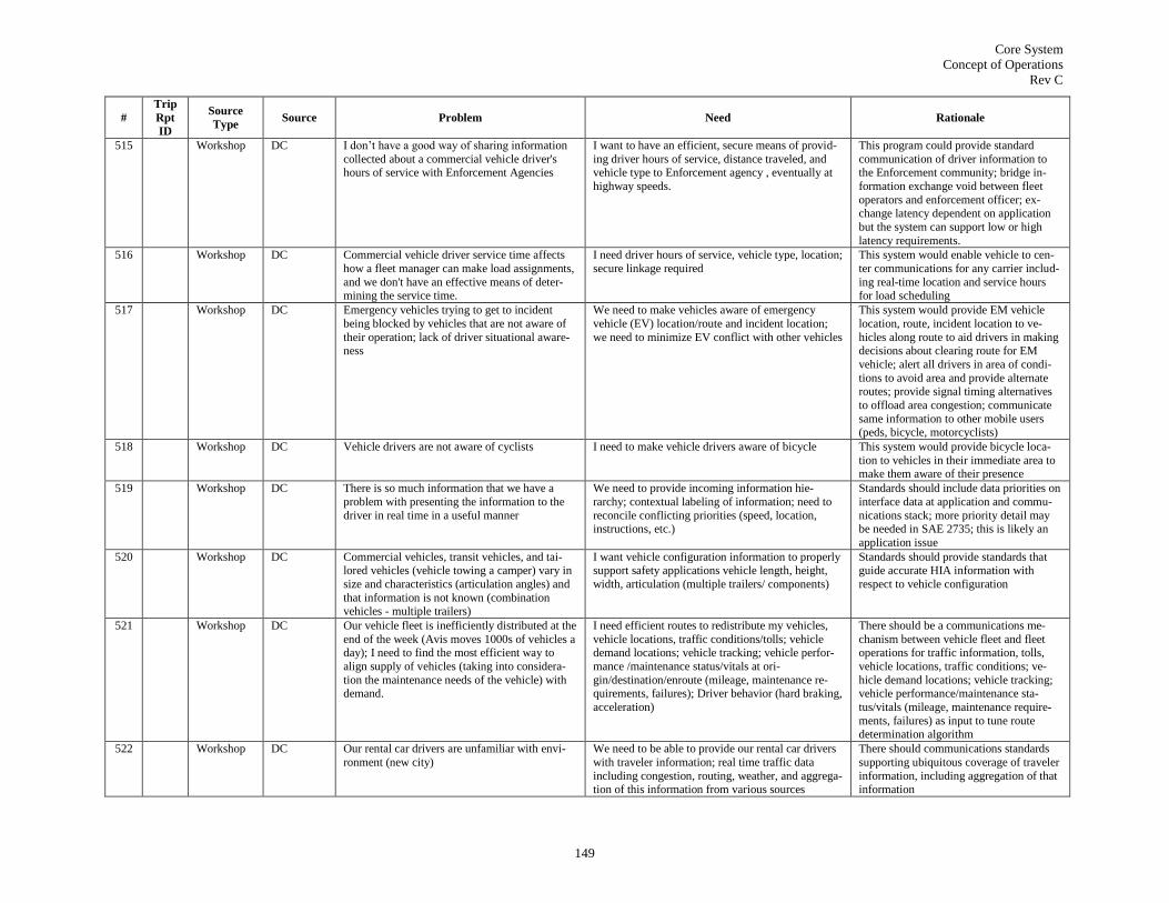
Core System
Concept of Operations
Rev C
149
#
Trip
Rpt
ID
Source
Type Source Problem Need Rationale
515 Workshop DC I don‘t have a good way of sharing information
collected about a commercial vehicle driver's hours of service with Enforcement Agencies
I want to have an efficient, secure means of provid-
ing driver hours of service, distance traveled, and vehicle type to Enforcement agency , eventually at
highway speeds.
This program could provide standard
communication of driver information to the Enforcement community; bridge in-
formation exchange void between fleet
operators and enforcement officer; ex-change latency dependent on application
but the system can support low or high
latency requirements.
516 Workshop DC Commercial vehicle driver service time affects
how a fleet manager can make load assignments,
and we don't have an effective means of deter-mining the service time.
I need driver hours of service, vehicle type, location;
secure linkage required
This system would enable vehicle to cen-
ter communications for any carrier includ-
ing real-time location and service hours for load scheduling
517 Workshop DC Emergency vehicles trying to get to incident
being blocked by vehicles that are not aware of
their operation; lack of driver situational aware-ness
We need to make vehicles aware of emergency
vehicle (EV) location/route and incident location;
we need to minimize EV conflict with other vehicles
This system would provide EM vehicle
location, route, incident location to ve-
hicles along route to aid drivers in making decisions about clearing route for EM
vehicle; alert all drivers in area of condi-
tions to avoid area and provide alternate routes; provide signal timing alternatives
to offload area congestion; communicate
same information to other mobile users (peds, bicycle, motorcyclists)
518 Workshop DC Vehicle drivers are not aware of cyclists I need to make vehicle drivers aware of bicycle This system would provide bicycle loca-
tion to vehicles in their immediate area to make them aware of their presence
519 Workshop DC There is so much information that we have a
problem with presenting the information to the
driver in real time in a useful manner
We need to provide incoming information hie-
rarchy; contextual labeling of information; need to
reconcile conflicting priorities (speed, location, instructions, etc.)
Standards should include data priorities on
interface data at application and commu-
nications stack; more priority detail may be needed in SAE 2735; this is likely an
application issue
520 Workshop DC Commercial vehicles, transit vehicles, and tai-
lored vehicles (vehicle towing a camper) vary in
size and characteristics (articulation angles) and
that information is not known (combination vehicles - multiple trailers)
I want vehicle configuration information to properly
support safety applications vehicle length, height,
width, articulation (multiple trailers/ components)
Standards should provide standards that
guide accurate HIA information with
respect to vehicle configuration
521 Workshop DC Our vehicle fleet is inefficiently distributed at the
end of the week (Avis moves 1000s of vehicles a day); I need to find the most efficient way to
align supply of vehicles (taking into considera-
tion the maintenance needs of the vehicle) with demand.
I need efficient routes to redistribute my vehicles,
vehicle locations, traffic conditions/tolls; vehicle demand locations; vehicle tracking; vehicle perfor-
mance /maintenance status/vitals at ori-
gin/destination/enroute (mileage, maintenance re-quirements, failures); Driver behavior (hard braking,
acceleration)
There should be a communications me-
chanism between vehicle fleet and fleet operations for traffic information, tolls,
vehicle locations, traffic conditions; ve-
hicle demand locations; vehicle tracking; vehicle performance/maintenance sta-
tus/vitals (mileage, maintenance require-
ments, failures) as input to tune route
determination algorithm
522 Workshop DC Our rental car drivers are unfamiliar with envi-
ronment (new city)
We need to be able to provide our rental car drivers
with traveler information; real time traffic data
including congestion, routing, weather, and aggrega-tion of this information from various sources
There should communications standards
supporting ubiquitous coverage of traveler
information, including aggregation of that information
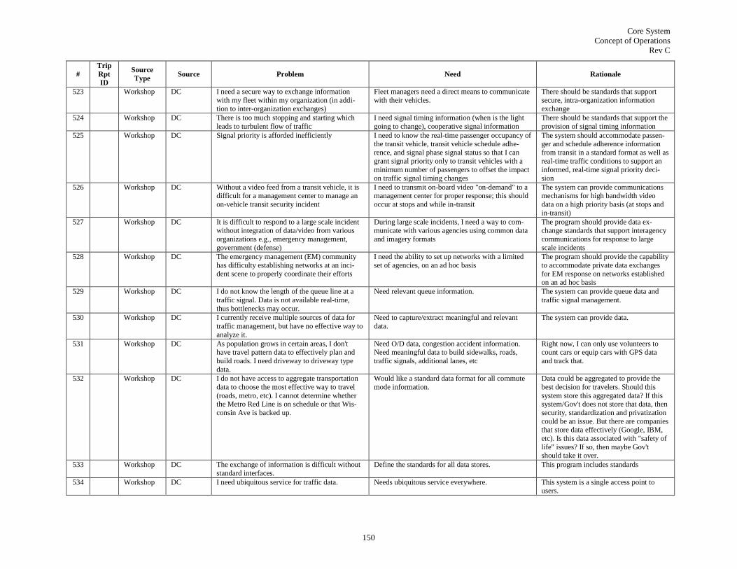
Core System
Concept of Operations
Rev C
150
#
Trip
Rpt
ID
Source
Type Source Problem Need Rationale
523 Workshop DC I need a secure way to exchange information
with my fleet within my organization (in addi-tion to inter-organization exchanges)
Fleet managers need a direct means to communicate
with their vehicles.
There should be standards that support
secure, intra-organization information exchange
524 Workshop DC There is too much stopping and starting which
leads to turbulent flow of traffic
I need signal timing information (when is the light
going to change), cooperative signal information
There should be standards that support the
provision of signal timing information
525 Workshop DC Signal priority is afforded inefficiently I need to know the real-time passenger occupancy of the transit vehicle, transit vehicle schedule adhe-
rence, and signal phase signal status so that I can
grant signal priority only to transit vehicles with a minimum number of passengers to offset the impact
on traffic signal timing changes
The system should accommodate passen-ger and schedule adherence information
from transit in a standard format as well as
real-time traffic conditions to support an informed, real-time signal priority deci-
sion
526 Workshop DC Without a video feed from a transit vehicle, it is difficult for a management center to manage an
on-vehicle transit security incident
I need to transmit on-board video "on-demand" to a management center for proper response; this should
occur at stops and while in-transit
The system can provide communications mechanisms for high bandwidth video
data on a high priority basis (at stops and
in-transit)
527 Workshop DC It is difficult to respond to a large scale incident without integration of data/video from various
organizations e.g., emergency management,
government (defense)
During large scale incidents, I need a way to com-municate with various agencies using common data
and imagery formats
The program should provide data ex-change standards that support interagency
communications for response to large
scale incidents
528 Workshop DC The emergency management (EM) community
has difficulty establishing networks at an inci-
dent scene to properly coordinate their efforts
I need the ability to set up networks with a limited
set of agencies, on an ad hoc basis
The program should provide the capability
to accommodate private data exchanges
for EM response on networks established on an ad hoc basis
529 Workshop DC I do not know the length of the queue line at a
traffic signal. Data is not available real-time,
thus bottlenecks may occur.
Need relevant queue information. The system can provide queue data and
traffic signal management.
530 Workshop DC I currently receive multiple sources of data for
traffic management, but have no effective way to
analyze it.
Need to capture/extract meaningful and relevant
data.
The system can provide data.
531 Workshop DC As population grows in certain areas, I don't have travel pattern data to effectively plan and
build roads. I need driveway to driveway type
data.
Need O/D data, congestion accident information. Need meaningful data to build sidewalks, roads,
traffic signals, additional lanes, etc
Right now, I can only use volunteers to count cars or equip cars with GPS data
and track that.
532 Workshop DC I do not have access to aggregate transportation
data to choose the most effective way to travel
(roads, metro, etc). I cannot determine whether the Metro Red Line is on schedule or that Wis-
consin Ave is backed up.
Would like a standard data format for all commute
mode information.
Data could be aggregated to provide the
best decision for travelers. Should this
system store this aggregated data? If this system/Gov't does not store that data, then
security, standardization and privatization
could be an issue. But there are companies that store data effectively (Google, IBM,
etc). Is this data associated with "safety of
life" issues? If so, then maybe Gov't should take it over.
533 Workshop DC The exchange of information is difficult without
standard interfaces.
Define the standards for all data stores. This program includes standards
534 Workshop DC I need ubiquitous service for traffic data. Needs ubiquitous service everywhere. This system is a single access point to users.

Core System
Concept of Operations
Rev C
151
#
Trip
Rpt
ID
Source
Type Source Problem Need Rationale
535 Workshop DC There is a lack of data for accessibility issues
(for mobility, ramps, etc). Includes those with impaired sight and hearing; and age related.
Standardization of data format is needed for transit,
walkways, elevators, etc.
No one else will. Constraint with the
American Disability Act. This is an issue that this program has to address.
536 Workshop DC Dissemination of information all users regardless
of cost.
Need to get custom data to users regardless of cost,
at some basic level.
It is the Gov't responsibility to provide this
data.
537 Workshop DC Driver is overwhelmed by information. Driver distraction issue (e.g., sounds, sights).
Need relevant real-time information (adjacent car distances, weather changes, Elk/Deer, etc).
This system can provide relevant data.
538 Workshop DC Minor fender benders remain unreported. Provide information on ALL traffic accidents direct-
ly from vehicles to management centers
Current system does not/cannot track
minor fender benders.
539 Workshop DC It is difficult for drivers to provide input to plan-ners and road managers.
Provide means to securely provide OD information from every vehicle to planning archives.
Increase the breadth of planning data.
540 Workshop DC Data is uncharacterized from various sources. Data from reliable sources are more valued and
should be weighted more.
This system COULD provide value to
reliable sources versus bad actors.
541 Document CAMP Security
Final Re-
port
There is a possibility that the system will expe-rience malicious attacks or technical defects.
Need to detect misbehavior and remove bad actors as well as malicious and revoked vehicles from the
system
542 Document CAMP
Security
Final Re-port
Entities will not use this program if they cannot
trust it and the other entities connected through it
Need to provide proof of identification of entities so
they can be authenticated
543 Document CAMP
Security
Final Re-port
Communication messages can be tampered with Need to have confidence that the messages have not
been tampered with in transit.
544 Document CAMP
Security Final Re-
port
A trusted or certified vehicle could still start
sending spurious (invalid) messages.
Need to have non-repudiation or traceability of the
sender for an authority to have proof of wrongful or faulty messages content
545 Document CAMP
Security
Final Re-
port
Using a single security authentication record
over a large time-span would allow tracking of a
vehicle
Each vehicle needs to be loaded with a set of securi-
ty authentication records that are regularly changed
546 Document CAMP Security
Final Re-
port
Non-safety applications could interfere with safety applications
Need to ensure that non-safety applications do not interfere with safety applications
547 Document CAMP
Security
Final Re-port
Various threats will exist against the system There is a need to provide countermeasures to the
threats
548 Document CAMP
Security
Final Re-port
Entities want to retain their privacy to various
levels
Need to provide participating entities with a certain
level of privacy
549 Document CAMP
Security Final Re-
port
Security scheme denies the behaving vehicle of
access to transportation services
The security scheme needs to support behaving
vehicle mobility.

Core System
Concept of Operations
Rev C
152
#
Trip
Rpt
ID
Source
Type Source Problem Need Rationale
550 1 Workshop San Anto-
nio
There is currently no efficient and accurate way
to determine the number of riders on a bus.
Information on the number of riders on a bus would
determine the bus route options (dynamic routing) and behavior (signal priority usage or not). Histori-
cal data on ridership counts may also be used to help
determine what the riders pay for that route.
This system could help determine the
ridership counts on buses. It can provide data to analyze and to provide options.
551 2 Workshop San Anto-nio
In some Transit Parking lots, there is no way to determine the number of available parking spac-
es for transit riders or where the available park-ing spaces are located.
Information on where the available parking spaces are located or if there are no spaces available at all.
Parking lots and ramps can provide data to the vehicle for availability or parking
spaces and where they are located.
552 3 Workshop San Anto-
nio
There is no way to publicize information to
others for planning purposes. There needs to be a
way to collect lots of transit and mode informa-tion.
A means to collect and publicize data. This system should help to collect this
data. This system may or may not store it,
but it should be a central focal point to collect it.
553 4 Workshop San Anto-
nio
Mobility data is typically unavailable because of
the current transit "close systems". There is a need for standards, including standard interfaces
and open system approach for sharing data.
There is a need for standard interfaces and an open
system design for sharing data.
This system should help since it will be
based on an open system design with standard interfaces. In addition, this sys-
tem will likely be the central focal point
for collecting data.
554 5 Workshop San Anto-
nio
If there are no standards, then vehicle manufac-
turers will do their own thing. Your mod-
el/design cannot vary or discriminate from each
other.
You would need the OEMs to standardize their HMI
designs.
Can this program help here? OEMs will
likely work on their own internal HMI
designs, but still abide by interface and
msg standards.
555 6 Workshop San Anto-
nio
Different manufacturers will likely produce
different type radios, and messages may not be
compatible.
Each manufacturer may produce their own radio
type, but as a standard, messages and interfaces will
be compatible.
This program supports both msg standards
and interface standards. As long as the
Embedded or After-Market manufacturers abide by those standards, those radios will
be interoperable.
556 7 Workshop San Anto-
nio
Senior citizens are waiting too long for a bus at a
Senior Center.
Utilize the "call and ride" system to divert a bus
route to pick up those Senior citizens that are wait-ing. Provide updated schedule information to the
Senior Center of the buses route.
This system can provide optimized dy-
namic routing for diverted buses. To also provide updated bus schedule information
to the Senior Center.
557 8 Workshop San Anto-nio
Trains do not provide schedule updates or changes for commuters to be aware of.
Trains need to provide schedule changes and up-dates.
This system may assist with notifying commuters of train schedule changes.
558 9 Workshop San Anto-
nio
There are too many pedestrian crosswalk lights
that take longer than needed, which affects the traffic signal switching, which impacts traffic
flow through that intersection.
Some "fair way" to provide crossing for pedestrians
without traffic waiting too long to flow again.
This system could monitor pedestrian
crossing and dynamically change the traffic signal when there are no more
pedestrians to cross.
559 10 Workshop San Anto-
nio
Buses are idling way too much and at times are
being "queued up" (bunching) behind each other.
Provide vehicle information to inform buses and
provide options to avoid queue and idling time.
By providing other vehicle and bus infor-
mation (e.g., position, time) and signaliza-tion, you can avoid bunching and idling.
You may not need a command center, the
buses would be provided this information and make their own adjustments.
560 11 Workshop San Anto-
nio
Draw bridges, train crosses, convoys may block
traffic flow too frequently and unnecessarily.
Traffic information to provide mobility options. This is an opportunity to integrate traffic
information with other data to optimize traffic flow.
561 12 Workshop San Anto-
nio
There is not enough information to determine the
best route to take.
Traffic and vehicular information This system should be able to provide this
information.

Core System
Concept of Operations
Rev C
153
#
Trip
Rpt
ID
Source
Type Source Problem Need Rationale
562 13 Workshop San Anto-
nio
There is currently no way of informing drivers
when traffic signals are out (e.g., due to power failure), until they are at that intersection.
Inform drivers of traffic system failures, so that they
can choose their routes better.
This system should be able to provide this
information to drivers.
563 14 Workshop San Anto-
nio
There is no way to get enough information of a
route for me to choose.
Inform drivers to as much traffic information as
possible, so that they can choose their routes better.
This system should be able to provide this
information to drivers.
564 15 Workshop San Anto-nio
Vehicles are congested, they brake too much, accelerate too fast, which increases pollution.
Provide carbon footprint information to the driver, so they could adjust their driving behavior and
speed (assuming they are a good citizen). Maybe an
"I smell you" message?
This system could provide this carbon footprint information.
565 16 Workshop San Anto-
nio
Road usage fee is not fair. Need usage pricing with a better idea. Pay as you
drive pricing is the fairest.
This system could provide this informa-
tion to local/state entities.
566 17 Workshop San Anto-
nio
What is my best route? Multi-modal approach. Need information for op-
tions to get to work, How much it costs, how long is it and how much pollution did I make.
This system should be able to provide this
information to drivers.
567 18 Workshop San Anto-
nio
One day a week, I am allowed to telecommute.
There is not enough information to determine whether today is my day to telecommute or not.
Traffic, vehicular and mobility information This system should be able to provide this
information to drivers.
568 Workshop DC These systems will likely compete with well-
established proprietary Transit closed systems.
The Core System architecture should be more open
source, open system designed with standards and
established secure protocols; and with additional interface capabilities than previous proprietary
systems.
Proprietary systems that do not have open
interfaces which limit their capability to
provide information to all and are likely less secure than standard protocols.
569 Workshop DC Wireless devices do not currently have a way to downloaded certificates to provide secure comm
interfaces.
There is a need for a Certification Authority (CA) that is centrally managed and controlled.
A centrally managed and controlled CA system would be more efficient and se-
cure.
570 Workshop DC There are no well-managed evacuation routes
and procedures for drivers and pedestrians for hurricanes, flooding and earthquakes.
This program would provide evacuation routes and
procedural information to targeting drivers and pedestrian.
For emergency situations, this program
provides a means for implementing evacu-ations for local, state and Federal Gov'ts.
571 Workshop DC Transit information is not available to most
riders and pedestrians (pedestrians might become riders knowing transit information).
Need to provide Bus ID, GPS, vehicle status, speed,
pass counts and pre-payment info.
If Transit data were made available, it
would help riders and would provide pedestrians with more information to ride
or not.
572 Workshop DC Maintenance Decision Support Systems (MDSS) needs additional data for maintenance actions.
MDSS needs to determine best courses of action for snow removal, painting and other maintenance
decisions.
MDSS receives partial or inaccurate main-tenance information or (in the case of
snow removal) data is not real-time. Poss-
ible information path: Vehicles and RWIS->NCAR (Vehicle Data Translator -
VDT)->Clarus (storage)->State DOT,
MDSS
573 Workshop DC On Code Red Days, there is no way to provide information to divers to reduce or control emis-
sions.
A need to control the "carbon footprint" for each driver and/or to provide more information to decide
on driver options.
This program can enable emissions miti-gation response plans to provide a more
―green‖ solution (carbon footprint). This
includes speed limits, less braking, slower
acceleration and suggestions for better
performance. For fleets, in particular, this
is a cost savings.
574 Workshop DC There is little that can be done to control vehicle
emissions.
Federal funding is a way to mandate emissions
control, which would force the state and local Gov'ts
to take procedures for controlling emissions output.
Cities need to control their pollution levels
and this program can help the state and
local Gov'ts control emission levels.
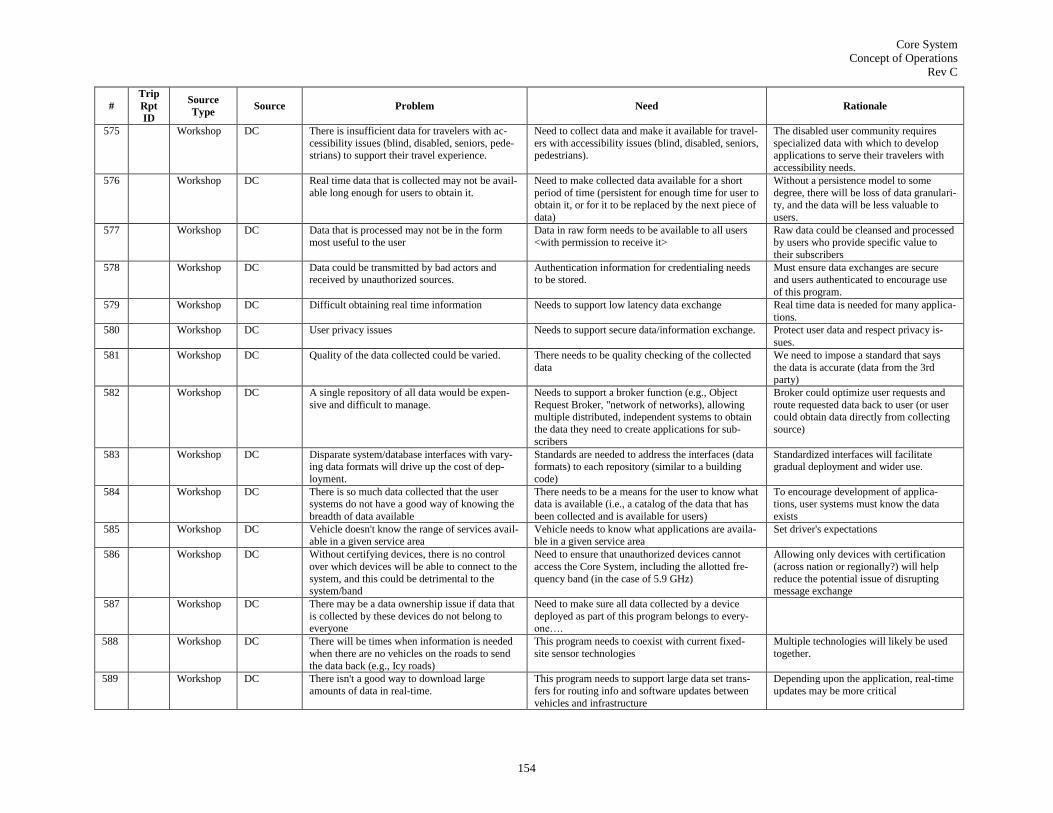
Core System
Concept of Operations
Rev C
154
#
Trip
Rpt
ID
Source
Type Source Problem Need Rationale
575 Workshop DC There is insufficient data for travelers with ac-
cessibility issues (blind, disabled, seniors, pede-strians) to support their travel experience.
Need to collect data and make it available for travel-
ers with accessibility issues (blind, disabled, seniors, pedestrians).
The disabled user community requires
specialized data with which to develop applications to serve their travelers with
accessibility needs.
576 Workshop DC Real time data that is collected may not be avail-
able long enough for users to obtain it.
Need to make collected data available for a short
period of time (persistent for enough time for user to obtain it, or for it to be replaced by the next piece of
data)
Without a persistence model to some
degree, there will be loss of data granulari-ty, and the data will be less valuable to
users.
577 Workshop DC Data that is processed may not be in the form most useful to the user
Data in raw form needs to be available to all users <with permission to receive it>
Raw data could be cleansed and processed by users who provide specific value to
their subscribers
578 Workshop DC Data could be transmitted by bad actors and received by unauthorized sources.
Authentication information for credentialing needs to be stored.
Must ensure data exchanges are secure and users authenticated to encourage use
of this program.
579 Workshop DC Difficult obtaining real time information Needs to support low latency data exchange Real time data is needed for many applica-
tions.
580 Workshop DC User privacy issues Needs to support secure data/information exchange. Protect user data and respect privacy is-
sues.
581 Workshop DC Quality of the data collected could be varied. There needs to be quality checking of the collected
data
We need to impose a standard that says
the data is accurate (data from the 3rd party)
582 Workshop DC A single repository of all data would be expen-
sive and difficult to manage.
Needs to support a broker function (e.g., Object
Request Broker, "network of networks), allowing multiple distributed, independent systems to obtain
the data they need to create applications for sub-
scribers
Broker could optimize user requests and
route requested data back to user (or user could obtain data directly from collecting
source)
583 Workshop DC Disparate system/database interfaces with vary-ing data formats will drive up the cost of dep-
loyment.
Standards are needed to address the interfaces (data formats) to each repository (similar to a building
code)
Standardized interfaces will facilitate gradual deployment and wider use.
584 Workshop DC There is so much data collected that the user systems do not have a good way of knowing the
breadth of data available
There needs to be a means for the user to know what data is available (i.e., a catalog of the data that has
been collected and is available for users)
To encourage development of applica-tions, user systems must know the data
exists
585 Workshop DC Vehicle doesn't know the range of services avail-able in a given service area
Vehicle needs to know what applications are availa-ble in a given service area
Set driver's expectations
586 Workshop DC Without certifying devices, there is no control
over which devices will be able to connect to the
system, and this could be detrimental to the system/band
Need to ensure that unauthorized devices cannot
access the Core System, including the allotted fre-
quency band (in the case of 5.9 GHz)
Allowing only devices with certification
(across nation or regionally?) will help
reduce the potential issue of disrupting message exchange
587 Workshop DC There may be a data ownership issue if data that
is collected by these devices do not belong to everyone
Need to make sure all data collected by a device
deployed as part of this program belongs to every-one….
588 Workshop DC There will be times when information is needed
when there are no vehicles on the roads to send
the data back (e.g., Icy roads)
This program needs to coexist with current fixed-
site sensor technologies
Multiple technologies will likely be used
together.
589 Workshop DC There isn't a good way to download large
amounts of data in real-time.
This program needs to support large data set trans-
fers for routing info and software updates between
vehicles and infrastructure
Depending upon the application, real-time
updates may be more critical

Core System
Concept of Operations
Rev C
155
#
Trip
Rpt
ID
Source
Type Source Problem Need Rationale
590 Workshop DC Without "guarantee" of message delivery, appli-
cations requiring real-time coordination -- such as safety applications - cannot be supported
Need to provide mechanism that ensures data is
delivered to support safety applications
Safety applications that require coordina-
tion will need a "guarantee" of delivery
591 Workshop DC It is unclear how multiple wireless integrated
transportation system technologies will coexist.
This program needs to support all technologies (3G,
4G, plus 5.9 for safety), the selection of which de-
pends on determination of which technology is best for which services and security rules for each
Multiple technologies will be available to
support transportation applications, so
there is a desire for them to converge.
592 Workshop DC For many applications, particularly safety appli-
cations, data must be accurate
Need accurate data exchange Support safety applications; utility of data
for data users/applications developers who depend upon the quality of data.
593 Workshop DC Difficult obtaining real time information Need all data publishers to be dynamic Real-time information is required.
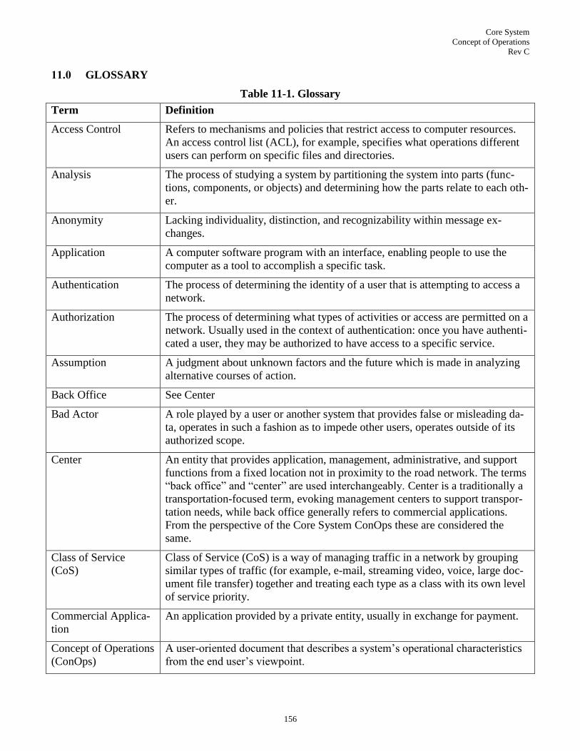
Core System
Concept of Operations
Rev C
156
11.0 GLOSSARY
Table 11-1. Glossary
Term Definition
Access Control Refers to mechanisms and policies that restrict access to computer resources.
An access control list (ACL), for example, specifies what operations different
users can perform on specific files and directories.
Analysis The process of studying a system by partitioning the system into parts (func-
tions, components, or objects) and determining how the parts relate to each oth-
er.
Anonymity Lacking individuality, distinction, and recognizability within message ex-
changes.
Application A computer software program with an interface, enabling people to use the
computer as a tool to accomplish a specific task.
Authentication The process of determining the identity of a user that is attempting to access a
network.
Authorization The process of determining what types of activities or access are permitted on a
network. Usually used in the context of authentication: once you have authenti-
cated a user, they may be authorized to have access to a specific service.
Assumption A judgment about unknown factors and the future which is made in analyzing
alternative courses of action.
Back Office See Center
Bad Actor A role played by a user or another system that provides false or misleading da-
ta, operates in such a fashion as to impede other users, operates outside of its
authorized scope.
Center An entity that provides application, management, administrative, and support
functions from a fixed location not in proximity to the road network. The terms
―back office‖ and ―center‖ are used interchangeably. Center is a traditionally a
transportation-focused term, evoking management centers to support transpor-
tation needs, while back office generally refers to commercial applications.
From the perspective of the Core System ConOps these are considered the
same.
Class of Service
(CoS)
Class of Service (CoS) is a way of managing traffic in a network by grouping
similar types of traffic (for example, e-mail, streaming video, voice, large doc-
ument file transfer) together and treating each type as a class with its own level
of service priority.
Commercial Applica-
tion
An application provided by a private entity, usually in exchange for payment.
Concept of Operations
(ConOps)
A user-oriented document that describes a system‘s operational characteristics
from the end user‘s viewpoint.
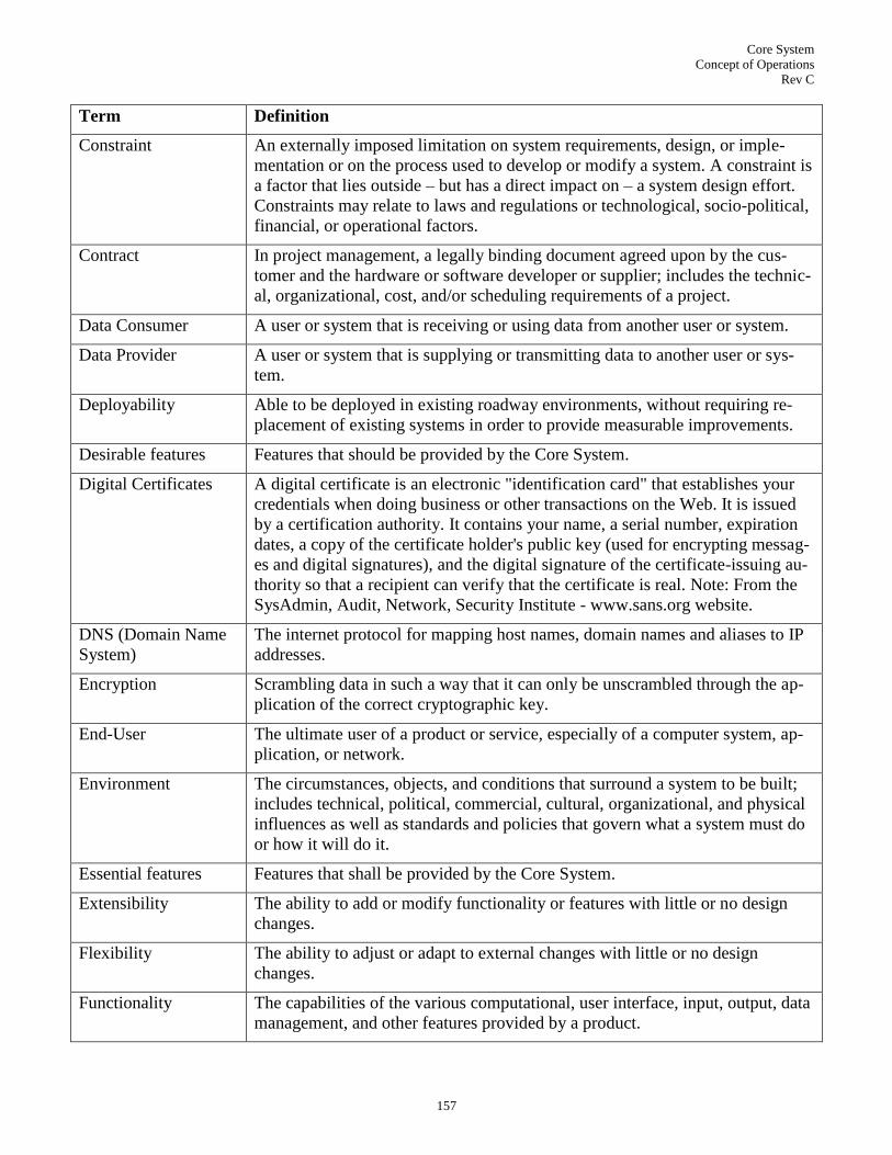
Core System
Concept of Operations
Rev C
157
Term Definition
Constraint An externally imposed limitation on system requirements, design, or imple-
mentation or on the process used to develop or modify a system. A constraint is
a factor that lies outside – but has a direct impact on – a system design effort.
Constraints may relate to laws and regulations or technological, socio-political,
financial, or operational factors.
Contract In project management, a legally binding document agreed upon by the cus-
tomer and the hardware or software developer or supplier; includes the technic-
al, organizational, cost, and/or scheduling requirements of a project.
Data Consumer A user or system that is receiving or using data from another user or system.
Data Provider A user or system that is supplying or transmitting data to another user or sys-
tem.
Deployability Able to be deployed in existing roadway environments, without requiring re-
placement of existing systems in order to provide measurable improvements.
Desirable features Features that should be provided by the Core System.
Digital Certificates A digital certificate is an electronic "identification card" that establishes your
credentials when doing business or other transactions on the Web. It is issued
by a certification authority. It contains your name, a serial number, expiration
dates, a copy of the certificate holder's public key (used for encrypting messag-
es and digital signatures), and the digital signature of the certificate-issuing au-
thority so that a recipient can verify that the certificate is real. Note: From the
SysAdmin, Audit, Network, Security Institute - www.sans.org website.
DNS (Domain Name
System)
The internet protocol for mapping host names, domain names and aliases to IP
addresses.
Encryption Scrambling data in such a way that it can only be unscrambled through the ap-
plication of the correct cryptographic key.
End-User The ultimate user of a product or service, especially of a computer system, ap-
plication, or network.
Environment The circumstances, objects, and conditions that surround a system to be built;
includes technical, political, commercial, cultural, organizational, and physical
influences as well as standards and policies that govern what a system must do
or how it will do it.
Essential features Features that shall be provided by the Core System.
Extensibility The ability to add or modify functionality or features with little or no design
changes.
Flexibility The ability to adjust or adapt to external changes with little or no design
changes.
Functionality The capabilities of the various computational, user interface, input, output, data
management, and other features provided by a product.

Core System
Concept of Operations
Rev C
158
Term Definition
Geo-cast The delivery of a message to a group of network destinations identified by their
geographical locations.
Hardware Hardware refers to the physical parts of a computer and related devices. Inter-
nal hardware devices include motherboards, hard drives, and memory. External
hardware devices include monitors, keyboards, mice, printers, and scanners.
Jurisdictional Scope The power, right, or authority to interpret and apply the law within the limits or
territory which authority may be exercised.
Maintainability To keep in an existing operational state preserved from failure or decline of
services (with minimum repair, efficiency, or validity).
Optional features Features that might be provided by the Core System.
On-Board Equipment
(OBE)
Computer modules, display and a DSRC radio, that is installed and embedded
into vehicles which provide an interface to vehicular sensors, as well as a wire-
less communication interface to the roadside and back office environment.
Point of Service The Core System which provides a ―gatekeeping arrangement‖ to connected
System Users with functions and capabilities.
Priority A rank order of status, activities, or tasks. Priority is particularly important
when resources are limited.
Privacy The ability of an individual to seclude information about themselves, and the-
reby reveal information about themselves selectively.
Problem domain A set of similar problems that occur in an environment and lend themselves to
common solutions.
Reliability Providing consistent and dependable system output or results.
Request for Quotation
(RFQ)
A request for services, research, or a product prepared by a customer and deli-
vered to a contractor with the expectation that the contractor will respond with
their proposed cost, schedule, and development approach.
Scalability The capable of being easily grown, expanded or upgraded upon demand with-
out requiring a redesign.
Scenario A step-by-step description of a series of events that may occur concurrently or
sequentially.
Service A set of related functionalities accessed using a prescribed interface.
Software Software is a general term that describes computer programs. Terms such as
software programs, applications, scripts, and instruction sets all fall under the
category of computer software.
States or Modes A distinct system setting in which the same user input will produce different
results than it would in other settings. Note: MIL STD 961E uses States and
Modes interchangeably.

Core System
Concept of Operations
Rev C
159
Term Definition
System (A) A collection of interacting components organized to accomplish a specified
function or set of functions within a specified environment.
(B) A group of people, objects, and procedures constituted to achieve defined
objectives of some operational role by performing specified functions. A com-
plete system includes all of the associated equipment, facilities, material, com-
puter programs, firmware, technical documentation, services, and personnel
required for operations and support to the degree necessary for self-sufficient
use in its intended environment.
System Need A capability that is identified and supported within the Core System to accom-
plish a specific goal or solve a problem.
Traceability The identification and documentation of derivation paths (upward) and alloca-
tion or flow down paths (downward) of work products in the work product hie-
rarchy. Important kinds of traceability include: to or from external sources to or
from system requirements; to or from system requirements to or from lowest
level requirements; to or from requirements to or from design; to or from de-
sign to or from implementation; to or from implementation to test; and to or
from requirements to test.
Trust Credentials A user‘s authentication information which determines permissions and/or al-
lowed actions with a system and other users.
Uni-cast The sending of a message to a single network destination identified by a unique
address.
User An individual who uses a computer, program, network, and related services of
a hardware and/or software system, usually associated with granting that indi-
vidual with an account and permissions.
User Need A capability that is identified to accomplish a specific goal or solve a problem
that is to be supported by the system. A user requirement for a system that a
user believes would solve a problem experienced by the user.
User Classes A category of user, typically with different user profiles and access rights to the
system.


