CÓDIGOS AVERÍA EQUIPOS CLIMATIZACIÓN DICORE lite Split ...
29
CÓDIGOS AVERÍA EQUIPOS CLIMATIZACIÓN DICORE lite Split pared 1+1 R32 inverter ASDAX12R3(1FR) www.dicore.es
Transcript of CÓDIGOS AVERÍA EQUIPOS CLIMATIZACIÓN DICORE lite Split ...

CÓDIGOS AVERÍAEQUIPOS CLIMATIZACIÓN DICORE lite
Split pared 1+1 R32 inverter
ASDAX12R3(1FR)
www.dicore.es

22
7. Maintenance
7-1 Troubleshooting Guide
Many error codes many appears on this air conditionor, and this troubleshootingguide is prepared for the maintenance personnel to detect the error position and theparts to be replaced during the troubleshooting process. In this Guide, theTroubleshooting Method is guided by the Error Name, and the Reference Code underthe General Index is the error code of the internal unit of the mainstream modelsupplied by the Company.
Example: “internal coil sensor error” is coded as E3 in the error code of the internalunit, but appears as flash-out via the trouble light of the external machine. However,their troubleshooting method is the same, and use the same table as well.
General index:No. Error Name Reference Code1 Internal temperature sensor error E12 External coil sensor error E23 Internal coil sensor error E3
4 Internal fan error of wall mounted airconditioner(PG motor) E4
5 Internal fan error of wall mounted airconditioner(DC motor) E4
6 Sliding door error of floor standing E47 Internal and external communication error E5(5E)8 External DC fan error (3-core terminal motor) F09 Module protection error F110 PFC protection error F211 Compressor startup error F312 Exhaust sensor error F413 Pressing top head sensor error F514 External temperature sensor error F615 OVP or UVP error F7
16 Main external control panel and module panelcommunication error F8
17 Outdoor EE error F9
18 Recirculated sensor error(four-way valve switcherror) FA
19 Cabinet internal fan error (see E4 fortroubleshooting) Fb
20 Function protection prompt of frequencyconversion external machine See the Error List

23
Example:
Explanationof error
Cause: explain the principle of the specific error.Inspection path: The basic order of troubleshooting. Related keyposition
Tools requiredfor inspection
Tools that should be carried for such troubleshooting, andreplacing parts that may be necessary for such error.
Frequentproblematic
part
Any possibly broken part related to the error may be the parts thatneed to be replaced.
Inspectionprocedureand keypoints
All the troubleshooting procedures for the reference ofmaintenance staff are prepared from simple to complex, fromsurface to internal, and from test to replacement. Although thesekey points do not cover all the error, and difficult or specialproblems are not included as well, but they can cover most of thecommon error.
Specialattention
Here are some often-overlooked problems for the reference of themaintenance personnel.
The problems in the market are always more than we think, so it is necessary for themaintenance personnel to understand the principle of air conditioning operation, andto make a flexible judgment of the fault in combination with the actual conditions. Wewe qlcome the maintenance personnel to constantly put forward new problems in theactual work, record the solutions and enrich our troubleshooting guide list.

24
(1)E1- internal temperature sensor error
Explanation oferror
Cause: The detection of short circuit or open circuit of internaltemperature sensor during the inspection of main control panel in theinternal machine, indicated by “internal temperature sensor error”.Inspection path: Sensor→Sensor wire→Connectors→Main internalcontrol panel
Tools requiredfor inspection Multimeter, 15KΩ standard sensor(25)
Frequentproblematic part Internal temperature sensor, main internal control panel
Inspectionprocedure andkey points
1. Check whether there’s resistance problem, short circuit or opencircuit in the sensor; the resistance value shall be within a reasonablerange (15KΩ under the temperature of 25 for frequency conversionmachine)2. Check whether the sensor wire is broken.3. Check whether the terminal connectors are well fixed; checkwhether the weld between the terminal and the main control panel isloose, and pull the terminal slightly for inspection if necessary.4. Check whether the sensor is affected with damp.5. In case no standard sensor is available at present, replace the internaltemperature sensor by other sensor asides, and then check whether theerror still exists; if the error disappears, replace the sensor; if the errorstill exists, check the main internal control panel and change ifnecessary.
Special attention
Most internal temperature sensors of the frequency conversionmachine have a resistance value of 15KΩ.Do not use improper sensor during repairing and maintenance, or itmay led to the wrong temperature sensing of the machine, the starterror or shutdown error. You can switch the air conditioner to the“Blowing” mode, and judge the accuracy of sensor thoughenvironmental temperature displayed on the screen.In case a sensor with the resistance value over 15KΩ is used, thedetected temperature will be much lower than the actual temperature,which may lead to the shutdown error under heating mode, or thestartup error under cooling mode.In case a sensor with the resistance value below 15KΩ is used, thedetected temperature will be much higher than the actual temperature,which may lead to the startup error under heating mode, or theshutdown error under cooling mode.
25
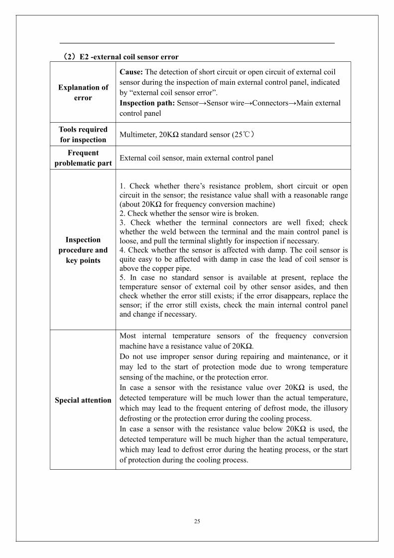
(2)E2 -external coil sensor error
Explanation oferror
Cause: The detection of short circuit or open circuit of external coilsensor during the inspection of main external control panel, indicatedby “external coil sensor error”.Inspection path: Sensor→Sensor wire→Connectors→Main externalcontrol panel
Tools requiredfor inspection Multimeter, 20KΩ standard sensor (25)
Frequentproblematic part External coil sensor, main external control panel
Inspectionprocedure andkey points
1. Check whether there’s resistance problem, short circuit or opencircuit in the sensor; the resistance value shall with a reasonable range(about 20KΩ for frequency conversion machine)2. Check whether the sensor wire is broken.3. Check whether the terminal connectors are well fixed; checkwhether the weld between the terminal and the main control panel isloose, and pull the terminal slightly for inspection if necessary.4. Check whether the sensor is affected with damp. The coil sensor isquite easy to be affected with damp in case the lead of coil sensor isabove the copper pipe.5. In case no standard sensor is available at present, replace thetemperature sensor of external coil by other sensor asides, and thencheck whether the error still exists; if the error disappears, replace thesensor; if the error still exists, check the main internal control paneland change if necessary.
Special attention
Most internal temperature sensors of the frequency conversionmachine have a resistance value of 20KΩ.Do not use improper sensor during repairing and maintenance, or itmay led to the start of protection mode due to wrong temperaturesensing of the machine, or the protection error.In case a sensor with the resistance value over 20KΩ is used, thedetected temperature will be much lower than the actual temperature,which may lead to the frequent entering of defrost mode, the illusorydefrosting or the protection error during the cooling process.In case a sensor with the resistance value below 20KΩ is used, thedetected temperature will be much higher than the actual temperature,which may lead to defrost error during the heating process, or the startof protection during the cooling process.

26
(3)E3 -internal coil sensor error
Explanation oferror
Cause: The detection of short circuit or open circuit of internal coilsensor during the inspection of main internal control panel, indicatedby “internal coil sensor error”.Inspection path: Sensor→Sensor wire→Connectors→Main internalcontrol panel
Tools requiredfor inspection Multimeter,, 5KΩ or 20KΩ standard sensoe(25)
Frequentproblematic part Internal temperature sensor, main internal control panel
Inspectionprocedure andkey points
1. Check whether there’s resistance problem, short circuit or opencircuit in the sensor; the resistance value shall with a reasonable range(about 20KΩ for frequency conversion machine)2. Check whether the sensor wire is broken.3. Check whether the terminal connectors are well fixed; checkwhether the weld between the terminal and the main control panel isloose., and pull the terminal slightly for inspection if necessary.4. Check whether the sensor is affected with damp. The coil sensor isquite easy to be affected with damp in case the lead of coil sensor isabove the copper pipe.5. In case no standard sensor is available at present, replace thetemperature sensor of internal coil by other sensor asides, and thencheck whether the error still exists; if the error disappears, replace thesensor; if the error still exists, check the main internal control paneland change if necessary.
Special attention
Most internal temperature sensors of the frequency conversionmachine have a resistance value of 20KΩ.Do not use improper sensor during repairing and maintenance, or itmay led to the start of anti-frosting or overheat protection mode due towrong temperature sensing of the machine.In case a sensor with the resistance value over 20KΩ is used, thedetected temperature will be much lower than the actual temperature,which may lead to the high pressure of cold-blast protection systemduring the heating process, or the frequent start of anti-freezingprotection during the cooling process.n case a sensor with the resistance value below 20KΩ is used, thedetected temperature will be much higher than the actual temperature,which may lead to the frequent start of overheat protection modeduring the heating or the overload protection during the coolingprocess.

27
(4)E4 -Internal fan error of wall mounted air conditioner(PG motor)
Explanation oferror
Cause: PG motor is equipped with speed feedback signal line. Whenthe feedback signal of speed is not received by the main internalcontrol panel, it has no way to recognize the rotating speed of motor,which will be indicated as “Internal fan error”. Main causes for thedisappearance of speed feedback signal are as follows:The fan is stucked; 2. The speed feedback component in the fan isbroken; 3. Error of receiving circuit for the speed feedback signal fromthe main internal control panel.
Tools requiredfor inspection Multimeter, A PG motor in normal working condition
Frequentproblematic part
Mechanical jam problem of internal fan, PG motor, main internalcontrol panel
Inspectionprocedure andkey points
1. Check whether the fan can work for a period of time before the erroroccurs. If yes, the reason of mechanical jam can be exclude.2. Disconnect the power supply and move the fan blade of internalmachine by hand to see if there’s any resistance. Some occasionalinternal fan error may relate to bearing coordination.3. Reconnect the drive wire and speed feedback wire, thus to excludeany fan error due to connector loosening.4. Check whether the plug-in terminal of speed feedback on the controlpanel is loose, and pull the terminal slightly for inspection if necessary.5. Replace the motor in the faulted air conditioner with other PG motor(do not fix it with the fan for the time being), if the main control panelstill indicates “internal fan error”, then replace the main internalcontrol panel; if the error disappears, replace the internal fan.
Special attention
The main internal control panel will not indicates “internal fanerror” when the internal fan is still rotating; sometimes such error willnot be reported when obvious fan problems exist (such as thelow-speed rotation due to damaged fan capacitors, or non-uniformrotating speed due to abnormal speed feedback.Therefore, patience of the maintenance staff is required for the
troubleshooting of fan error. You shall compare it with the normalcondition, and detect and solve the problem in a flexible way.

28
(5) E4- Internal fan error of wall mounted air conditioner (DC motor)
Explanation oferror
Cause: The internal fan of some highly energy efficient models is DCmotor using a green plug through which the main internal control panelcan drive the motor and sense the current rotational speed feedback.When the main internal control panel cannot receive the rotationalspeed feedback signal of the motor, it will indicate “DC motor error”.Disappearance of the rotational speed feedback signal may be causedby:1 The motor is stuck and cannot work; 2 The speed feedback elementinside the fan is destroyed; 3 There’s something wrong with the speedfeedback signal receiving circuit of the main internal control panel.Inspection path: Is DC motor stuck by foreign matter→motordestroyed → Motor terminal connectors→Main internal control panel
Tools requiredfor inspection Multimeter, a DC motor in normal working condition
Frequentproblematic part
Mechanical jam of internal fan, internal DC motor, main internalcontrol panel
Inspectionprocedure andkey points
1. Check whether the fan accelerates to extremely high speed beforethe error occurs. If it can work for a period, the reason of mechanicaljam can be excluded.2. Plug and unplug the terminal of the DC motor again to exclude anyfan error due to connector loosening, and pull the terminal slightly forinspection if necessary.3. Replace the motor in the faulted air conditioner with other DC motorto plug in the main internal control panel (do not fix it with the fan forthe time being), if the main control panel still indicates “DC motorerror”, then replace the main internal control panel; if the errordisappears, replace the DC motor.4. Multimeter can be used to distinguish whether it is main controlpanel problem or motor problem by: connect the motor with the maincontrol panel and pay attention to the second (yellow) and fourth(black) wire from the outermost side among four lines of the terminalof the DC motor. After the air conditioner powers on in the coolingmode for a while, the voltage between the yellow and black wiresshould rise gradually and the motor should accelerates slowly, if theDC motor still won’t rotate, then the DC motor is destroyed.
Special attention
Five lead wires division: Count from the outermost side of the fourwires of the DC motor terminal, the first blue wire is the speedfeedback wire with a voltage of 0.5-5V when the fan rotates; thesecond yellow wire is the motor driving wire with a voltage of2.0-7.5V when the fan rotates; the second white wire is 15V powercord with a voltage of 15V in normal condition; the fourth black wireis 0V DC earth wire which is the benchmark of all the voltage tests; thefifth (red) wire is 310V wire which is strong with a voltage of 310V innormal condition, so be careful of electric shock.

29
(6) E4- Sliding door error of floor standing
Explanation ofsliding door
error
Cause: For the model with upper and lower sliding doors, the positionof trap door is sensed via the upper and lower photoelectric switches.When the sliding door closes, it will move upward until the upperphotoelectric switch senses the sliding door; when the sliding dooropens, it will move downward until the lower photoelectric switchsenses the sliding door. When the photoelectric switch cannot sense theposition of the sliding door normally, it will indicate “sliding doorerror”.Inspection path: Mechanical jam of sliding plate →Synchronousmotor → Can synchronous motor connect to 220V power →photoelectric switch connection wire → Photoelectric switch → Maininternal control panel
Tools requiredfor inspection Multimeter, photoelectric switch in normal condition
Frequentproblematic part
Mechanical jam of sliding plate, photoelectric switch, reversiblesynchronous motor, main internal control panel
Inspectionprocedure andkey points
1. Power on and observe whether there is mechanical jam in the slidingplate. Note that new machines may be fixed by tapes, remove them.2. If the sliding door slides normally when the machine powers on andoff but it still indicates “sliding door error”, then there’s somethingwrong with the photoelectric switch.3. If the sliding door does not slide when the machine powers on andoff, check the reversible synchronous motor to see whether the motoris connected to 220V power or the motor’s wire is damaged.4. If there is something wrong with the photoelectric switch, replace itwith another one in normal condition and repeat the above procedures.If the error disappears, then it’s photoelectric problem; if not, then it’smain internal control panel problem.
Special attention
1. Please confirm that it is a new sealed one when replacing thephotoelectric switch.2. There are two photoelectric switches, so check the upper one whenthe error occurs when powering off and check the lower one when theerror occurs when powering on.3. Terminals connected to upper and lower photoelectric switchesshould be connected accordingly because they have different colors.Otherwise, it will lead to reverse switches for the sliding plate.

30
(7) E5(5E) -Internal and external communication error
Explanation oferror
Cause: The frequency converter needs internal and externalcommunication.When the communication cannot be reached, theinternal and external units will indicate “internal and externalcommunication error”. Only “main internal control panel, connectingcable and main external control panel” are related to communication;but sometimes the communication error will be indicated when theexternal unit has no power and the internal unit cannot connect withthe external unit due to other errors, then such situation shall bedistinguished from “pure communication error” and treated in adifferent way.Inspection path: Check if the external unit can power on and work(normally, the indicator light will turn off after lighting for severalseconds, relay picks up, and PTC won’t heat seriously)1. Can power on and work: Are the internal unit and external unitmatched→is the phase sequence of connecting wires of internal andexternal units correct (the live wire of the internal unit connects withthat of the external unit, the null wire of the internal unit connects withthat of the external unit)→Connecting wires touched well→Maininternal control panel replacement→Main external control panelreplacement2. Cannot power on and work: Can AC 220V be delivered to theterminal block of the external unit→Can the bridge rectifier andmodule panel generate DC 310V→Can the main external control panelgenerate a low voltage power supply of DC 5V→Does the mainexternal control panel show the status of periodical reset.
Tools requiredfor inspection Multimeter, main internal control panel in normal condition
Frequentproblematic part
Connecting wire phase sequence and contact, main internal controlpanel, main external control panel, module panel
Inspectionprocedure andkey points
1. Firstly, the IDU and the ODU should be matched and connectedproperly.2. Observe the main external control panel, turn on the air conditioner,three lights are all lighted up then off and the relay pulls in. If not, it ispower supply problem.3. Connect the black signal line S to terminal N of ODU. Turn on theA/C, if "E5" is still reported, the main external control panel need to bereplaced. If "E5" is still reported at this time, go to step 4.4. Change a new main internal control panel, if the error code E5remains, then the problem should be on the main external controlpanel.

31
Special attention
When the external unit not power on: If the internal terminal boarddoes not transmit 220V power, replace the main internal control panel;if the external terminal board has 220V power, first check if (fuse,reactor and bridge rectifier) are normal. There is still something wrong,replace the whole set of external control unit; for the control unitcomposed of several function boards, try disconnecting theweak-current data wires among several control boards and then powerthe external unit on, if the main control panel can be powered on andinitialized successfully, then it’s the module panel problems; if themain external control panel still cannot be powered on and initialized,replace the main external control panel.

32
(8) F0- External DC fan error (3-core terminal motor)
Explanation oferror
Cause: Our frequency changing external unit uses the 3-lead-wire DCmotor, or “externally driven DC motor” for short, after 2012. It has nospeed feedback circuit but 3 drive lead wires and its driving principle issimilar to that of the compressor. The main control panel will indicate“external DC fan error” when it detects imbalanced current on the threelead wires of the driving motor.Inspection path: Is the DC fan stuck by foreign matters→Motorterminal connectors→Main external control panel→Motor
Tools requiredfor inspection Main external control panel in normal condition
Frequentproblematic part
Mechanical jam of external fan, main external control panel, externalDC motor
Inspectionprocedure andkey points
1. First exclude the possibility of mechanical jam of external fanblades.。2. Observe if the terminal of the fan is not connected firmly or theorder of lead wires is correct. If the external fan of the newly installedair conditioner rotates reversely, first observe if the color order of thethree lead wires is correct, or change the order of any two of the threelead wires of the motor to see if the fan can rotate in the forwarddirection.3.The DC motor of this scheme is relatively simple and reliable, so theproblem is more likely to be caused by the drive part of the fan of themain external control panel. The maintenance personnel may as wellprepare matched main external control panel before maintenance. If thefan returns to normal after replacing the main control panel, then it’sthe main control panel problem; if it still indicates external DC motorerror, then replace the external DC motor.
Special attention
Unlike the 5-core internal DC motor, there will be a process of fanblade position locking before the 3-core DC motor with external drivestarts to rotate. The fan blades will shake mechanically for 3-5 secondsand then rotate slowly, which is normal phenomenon.

33
(9) F1 -Module protection error
Explanation oferror
Cause: The power module is the part to directly drive the compressorto work. It can protect the machine in time when overcurrent,overvoltage or overheat occurs and stops the compressor fromworking. It will, at the same time, send “shutdown request” to themodule panel. The error triggered by the “shutdown request” is called“module protection error”.Inspection path: Supply voltage → Compressor wire, reactor wire →System blocked → Module panel damaged → Main external controlpanel destroyed → Compressor destroyed
Tools requiredfor inspection
Multimeter, pressure gauge, megameter, module panel in normalcondition
Frequentproblematic part
Supply voltage, compressor wire, reactor, system pressure, modulepanel, main external control panel, compressor

34
Inspectionprocedure andkey points
1. Is the order of compressor wires not correct, which makes thecompressor rotate reversely? Try exchanging the compressor wires onU-V phase to see if the problem can be solved?2. Check if the supply voltage is unstable and highly volatile, and testif the system pressure is normal. High system pressure will causerotating problems to the compressor.3. Is the module panel fixed to the radiator firmly? Will it cause poolcooling? Is the internal and external heat exchanger dirty, which lead topoor heat transfer and high system pressure?4. If “module protection error” will be indicated immediately afterstarting up, it is almost certain that it’s substantial error, having nothingto do with supply voltage and system pressure, it is suggested toobserve if there is any component destroyed by strike arc near themodule panel; use the multimeter to test if the resistances between anytwo compressor wires are the same. The resistances between any twocompressor wires in normal condition are tiny resistances at ohm leveland are basically equal; then use the megameter to measure if theresistance insulation of the three compressor wires against the earthwire is good (normally at MΩ level), and check if the reactor wire iswell connected or the reactor is destroyed.5. Test if the 15V and 5V (3.3V) power supply on the module panel isstable and exclude the module panel error caused by power supply ofthe main external control panel.6. Methods for judging whether the power module is damaged: use the“diode position” of the multimeter to measure the features of P of themodule panel against U-V-W three phases respectively. Measure thepower module P-U, P-V and P-W, there is always infinite resistance atone side and fixed on-state voltage at the other side (generally 0.5V);measure the features between N-U, N-V and N-W in the same way, ifshort circuit occurs during any measurement, then the module isdestroyed.7. Replace with the module panel in normal condition for test. If thetest is normal after changing the module panel, then the originalmodule panel is destroyed.8. After excluding problems of module, connecting wires, system andpower supply, distinguish by ear. If there is only electromagnetic soundand the compressor does not work; or the sound of irregular runningappears after the compressor works for a while and then it shuts downand indicates error; chances are that the compressor is blocked ordestroyed, consider replacing the compressor.
35
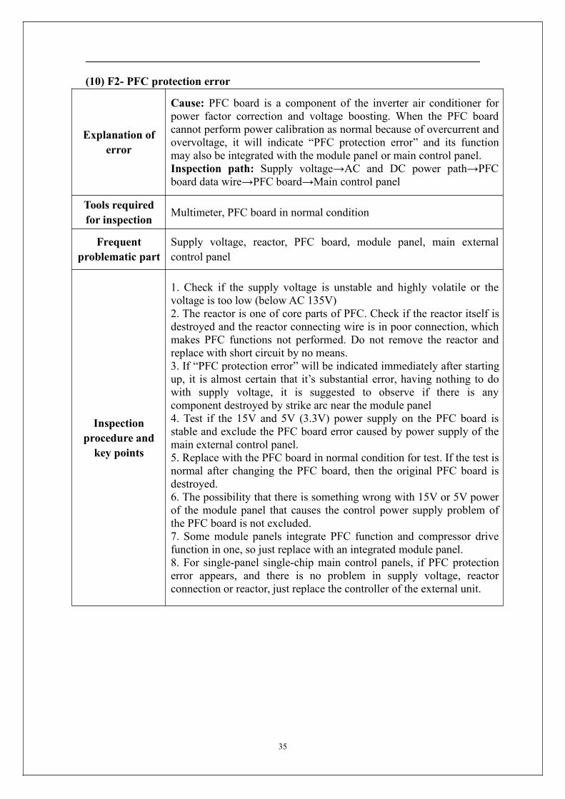
(10) F2- PFC protection error
Explanation oferror
Cause: PFC board is a component of the inverter air conditioner forpower factor correction and voltage boosting. When the PFC boardcannot perform power calibration as normal because of overcurrent andovervoltage, it will indicate “PFC protection error” and its functionmay also be integrated with the module panel or main control panel.Inspection path: Supply voltage→AC and DC power path→PFCboard data wire→PFC board→Main control panel
Tools requiredfor inspection Multimeter, PFC board in normal condition
Frequentproblematic part
Supply voltage, reactor, PFC board, module panel, main externalcontrol panel
Inspectionprocedure andkey points
1. Check if the supply voltage is unstable and highly volatile or thevoltage is too low (below AC 135V)2. The reactor is one of core parts of PFC. Check if the reactor itself isdestroyed and the reactor connecting wire is in poor connection, whichmakes PFC functions not performed. Do not remove the reactor andreplace with short circuit by no means.3. If “PFC protection error” will be indicated immediately after startingup, it is almost certain that it’s substantial error, having nothing to dowith supply voltage, it is suggested to observe if there is anycomponent destroyed by strike arc near the module panel4. Test if the 15V and 5V (3.3V) power supply on the PFC board isstable and exclude the PFC board error caused by power supply of themain external control panel.5. Replace with the PFC board in normal condition for test. If the test isnormal after changing the PFC board, then the original PFC board isdestroyed.6. The possibility that there is something wrong with 15V or 5V powerof the module panel that causes the control power supply problem ofthe PFC board is not excluded.7. Some module panels integrate PFC function and compressor drivefunction in one, so just replace with an integrated module panel.8. For single-panel single-chip main control panels, if PFC protectionerror appears, and there is no problem in supply voltage, reactorconnection or reactor, just replace the controller of the external unit.

36
(11) F3- Compressor out-of-step error
Explanation oferror
Cause: The module panel will constantly test the current of lead wiresof the compressor and calculate the position of the rotator of thecompressor when driving the compressor to work. When thecompressor deviates far from the normal operating status , it willindicate “compressor out-of-step error” because the current of thecompressor wires is too high or it cannot detect the position of therotator. This error always follows “module protection error”, so theyhave similar inspection methods.Inspection path: supply voltage→Compressor wire, reactor wire→System blocked→Module panel damaged→Main external controlpanel destroyed→Compressor destroyed
Tools requiredfor inspection Multimeter, pressure gauge, module panel in normal condition
Frequentproblematic part
Supply voltage, compressor wire, reactor, system pressure, modulepanel, main external control panel, compressor
Inspectionprocedure andkey points
1. Is the order of compressor wires not correct, which makes thecompressor rotate reversely? Try exchanging the compressor wires onU-V phase to see if the problem can be solved?2. Check if the supply voltage is unstable and highly volatile, and testif the system pressure is normal. High system pressure will causerotating problems to the compressor.3. Is the module panel fixed to the radiator firmly? Will it cause poolcooling? Is the internal and external heat exchanger dirty, which lead topoor heat transfer and high system pressure?4. If “compressor out-of-step error” will be indicated immediately afterstarting up, it is almost certain that it’s substantial error, having nothingto do with supply voltage and system pressure, it is suggested toobserve if there is any component destroyed by strike arc near themodule panel; use the multimeter to test if the resistances between anytwo compressor wires are the same. The resistances between any twocompressor wires in normal condition are tiny resistances at ohm leveland are basically equal; then use the megameter to measure if theresistance insulation of the three compressor wires against the earthwire is good (normally at MΩ level), and check if the reactor wire iswell connected or the reactor is destroyed. Check if the DC voltagebetween P-N is too high (above 200V).5. Test if the 15V and 5V (3.3V) power supply on the module panel isstable and exclude the module panel error caused by power supply ofthe main external control panel.6. Replace with the module panel in normal condition for test. If thetest is normal after changing the module panel, then the originalmodule panel is destroyed.7. After excluding problems of module, connecting wires, system andpower supply, distinguish by ear. If there is only electromagnetic soundand the compressor does not work; or the sound of irregular runningappears after the compressor works for a while and then it shuts downand indicates error; chances are that the compressor is blocked ordestroyed, consider replacing the compressor.

37
Special attention
For the “compressor out-of-step error” and “module protection error”,the former is calculated by the main chip of the module panel and thelatter is detected by the power module itself. They are abnormaloperating phenomenon of the compressor essentially. If there isuncertainty about either error, analyze both together with similarmethod. For inverter air conditioners that are in poor electricalenvironment or are old, occasional occurrence of such errors is anormal protection.
(12) F4- Exhaust sensor error
Explanation oferror
Cause: The main external control panel will indicate “exhaust sensorerror” and send it to the main internal control panel when it detectsshort circuit or open circuit of the exhaust sensor.Inspection path: Exhaust sensor→Sensor wire→Connectors→Mainexternal control panel
Tools requiredfor inspection Multimeter, 50KΩ standard exhaust sensor (25)
Frequentproblematic part Exhaust sensor, main external control panel
Inspectionprocedure andkey points
1. Check if there is any evident resistance problem in the sensor.Whether in short circuit or open circuit, the resistance should maintainin a reasonable range (about 50KΩ when the compressor is notworking and between 3 KΩ and 30 KΩ after the compressor works fora while, the corresponding exhaust temperature should be 100
-38).2. Check if the sensor wire or the sensor connecting wire is damaged.3. Check if the connecting terminal is connected firmly, the weldbetween the terminal and the main control panel is loose; pull theterminal slightly for inspection if necessary.4. Check whether the sensor is affected with damp. The coil sensor isquite easy to be affected with damp in case the lead wire of coil sensoris above the copper pipe.5. If there is no standard sensor at hand, exchange the exhaust sensorwith the one beside it to see if the error changes. If yes, there issomething wrong with the sensor and it should be replaced; if it stillindicates “external coil sensor error”, replace the main external controlpanel.
Special attention
Most exhaust sensors have a standard resistance of 50KΩ (25). Donot use improper sensor during maintenance, or the machine will sensethe exhaust temperature mistakenly and enters the protection statefrequently. For example, in the case where replace the 20KΩ coilsensor for the exhaust sensor by mistake, the exhaust temperature thatthe main external control panel senses will be higher than the actualexhaust temperature, which will make normal air conditioners enter thehigh exhaust temperature protection state frequently, and thecompressor frequency threshold will rise and lead to shutdown of thecompressor.

38
(13) F5 -Compressor top head sensor error
Explanation oferror
Cause: The compressor top head sensor is a compressor top headtemperature protection switch most of the time. It keeps closed (shortcircuit) when the compressor temperature is normal and switches off(open circuit) when the temperature is too high. The main externalcontrol panel will indicate “compressor top head sensor error” when itsenses disconnection of the compressor top head protection switch.Inspection path: Compressor top head sensor (temperature protectionswitch)→Sensor wire→Connectors→Main external control panel
Tools requiredfor inspection Pressure gauge, multimeter
Frequentproblematic part
System pressure, liquid deficiency, compressor top head sensor(temperature protection switch), main external control panel
Inspectionprocedure andkey points
1. First check if the compressor top head temperature is too high(above 110 ) and causes action of the compressor top head sensor(temperature protection switch); reasons why the compressor top headtemperature is too high may be: the system is deficient in liquid and thecompressor idles; the system is blocked and the pressure of thecompressor is too high.2. After excluding the possibility of the system problem, please notethat the temperature protection switch is closed normally. Test if theterminals of the sensor are in the short-circuit condition with themultimeter. In the case of open circuit, then there is something wrongwith the sensor or lead wires.3. Check if the sensor wire or the sensor connecting wire is damaged.4. Check if the connecting terminal is connected firmly, the weldbetween the terminal and the main control panel is loose; pull theterminal slightly for inspection if necessary.5. Disconnect the power supply and short circuit a metal with thecompressor top head terminal of the main external control panel. If thecompressor top head sensor error disappears after start up, then replacethe sensor; if the error still occurs, it’s probably the main control panelproblem, replace the main external control panel.
Special attentionThe compressor top head sensor is just a temperature switch which ishighly reliable and is less likely to go wrong generally. Pay moreattention to the system pressure and the compressor temperature.

39
(14)F6- external temperature sensor error
Explanation oferror
Cause: The detection of short circuit or open circuit of externaltermperature sensor during the inspection of main external controlpanel, indicated by "external termperature sensor error".Inspection path: Sensor→Sensor wire→Connectors→Main externalcontrol panel
Tools requiredfor inspection Multimeter, 15KΩ standard sensor(25)
Frequentproblematic part External temperature sensor, main external control panel.
Inspectionprocedure andkey points
1. Check whether there’s resistance problem, short circuit or opencircuit in the sensor; the resistance value shall be within a reasonablerange (15KΩ under the temperature of 25).2. Check whether the sensor wire is broken.3. Check whether the terminal connectors are well fixed; checkwhether the weld between the terminal and the main control panel isloose, and pull the terminal slightly for inspection if necessary.4. Check whether the sensor is affected with damp.5. In case no standard sensor is available at present, replace theexternal temperature sensor with the other sensor asides, and thencheck whether the error still exists; if the error disappears, replace thesensor; if the error still exists, it's possible that the main control panelis faulted, change the main external control panel.
Special attention
Most of the standard resistance values of the external temperaturesensors are 15KΩ (hen temeperature is at 25 ), and the higher thetemeprautre is, the lower the resistance value is, and the lower thetemperature is, the higher the resistance value is. Do not use impropersensor during repairing and maintenance, or it may led to the wrongtemperature sensing of the machine.

40
(15)F7-OVP or UVP error
Explanation oferror
Cause: All the inverter air conditioners are equipped with voltageinspection circuits, but differnt models of machines have differntlocations for the voltage inspection (on the modue panel or mainexternal control panel). When the supply voltage is lower than 135V orhigher than 275V, the inspectio circuit would detect over or undervoltage protection signal and send it to the main external control paneland the main external control panel would raise the alarm "OVP orUVP error" and indicate it through the internal motor.Inspection path: supply voltage → internal direct current voltage →reactor wiring → module panel → main external control panel.
Tools requiredfor inspection Multimeter
Frequentproblematic part Supply voltage, reactor, moduel panel and main external control panel.
Inspectionprocedure andkey points
1. First, check the supply environment of the user, especially shallcheck when the compressor of the air conditioner has been running fora while. The normal supply voltage shall be between 198V and 242Vand the minimum work assurance range of the air conditioner shall bewithin 165V and 265V and it shall be especially noted that the voltagevalue shall not be decreased significantly after running of thecompressor (voltage decreasing by over 25V), because if the supplyvoltage is decreased by a lot, it means the supply line capacity isinsufficient and the user is usually suggested to replace the circuit orinstall a specizlied air conditioner supply voltage stabilizer.2. For the external machines with PFC panels (without separaterectifier bridges), the operator shall ensure if the PFC function is onwith the direct current voltage grade of the multimeter. When thecompressor is running, voltage between P and N ends detected on thetest module panel or main external control panel shall be over 200Vand if the voltage is below that range, it is possible that the reactor isfaulted or the PFC is broken.3. When the air conditioner is switched on, if the compressor is notrunning but there is a alarm of "OVP or UVP error" and the powervoltage detected with the multimeter is not below 150V, it's probablythe voltage inspection circuit is faulted. The operator shall check andconfirm the voltage inspection circuit is on which control panel firstand then replace it. The regular replacement: for the external machineof single panel single chip, replace the external controller directly; andfor the machine of two panels, replace the module panel.
Special attention
For some models, OVP or UVP error signal is delivered through theconnector wires between the module panel and the main externalcontrol panel, thus it is possible the voltage signal is not deliveredwhen the communication between teh module panle and the mainexternal control panel is not good. It is possible that the error is fauseraised but after some minutes that the error is finally confirmed as"Main external control panel and module pannel communicationerror", which shall be specially noted.

41
(16)F8-main external control panel and module panel communication error(exclusive of external machine of single panel)
Explanation oferror
Cause: Only the models with the module panels separated with themain external control panels may have this error. When the machine isrunning normally, the module panel and the main external controlpanel would coordinate with each other on the communication to workand when the communication is off, the main external control panelwould raise the alarm of "main control panel and module panelcommunication error". Only "module panel, data line and mainexternal control panel" are related to such communication.Inspection path: data line connection → module panel power→module panel →main external control panel
Tools requiredfor inspection Multimeter and regular module panel.
Frequentproblematic part
Module panel and main control data line, module panel and mainexternal control panel.
Inspectionprocedure andkey points
1. First check if the communication connection line (mostly 4 chips)between the module panel and main contrl panel gets loose and if theconnection is faulted.2. Measure and check with a multimeter if the power from the mainexternal control panel is normal and especially note that if the 5V(3.3V) power is led to the module panel. Eleminate the possibility thatit's not running normally because there is no 5V (3.3V) power at themodule panel.3. The maintenance personnel shall replace the module panel of thefaulted air conditioner with a regular module panel taken with him andif the communication error disappears when the external machine isswitched on, it means the original module panel is faulted and if theerror is still there, maybe the main external control panel shall bereplaced.

42
(17)F9- outdoor EE error
Explanation oferror
Cause: Many parameters need to be preset for the running of theexternal unit of the air conditioner and such parameters are placed in adata storage 8-feet chip, which is called "EEPROM" or "EE" for short.The motor on the main external control panel can only work afterreading the data stored in EE and if not read, the alarm "outdoor EEerror" would be reported and raised in the internal machine. Reasonsfor data not being read are as follows:1. wrong EE chip data format;2. EE chip is broken;3. bad contact of EE or fault of EE reading circuit;4. backward installation of EE chip.Inspection path: main external control panel.
Tools requiredfor inspection None.
Frequentproblematic part Bad contact of EE, main external control panel.
Inspectionprocedure andkey points
1. Replace the main external control panel directly.

43
(18)FA- recirculated sensor error (only models of electronic expansion valvesare involved)
Explanation oferror
Cause: The recirculated sensors are only used on machine models ofelectronic expanssion valves and the back temperature value isconsidered as the basis for adjustment of the electronic expanssionvalve and determination if the four-way valve changes the positionnormally during heating. When the main control panel detects opencircuit or short circuit of the recirculated sensor, it would raise analarm of "recirculated sensor error" and send it to the main internalcontrol panel to indicate it.Inspection path: four-way valve →recirculated sensor → sensor wire→ connectors → main external control panel
Tools requiredfor inspection Multimeter, pressure meter, normal 20KΩ recirculated sensor
Frequentproblematic part Four-way valve, recirculated sensor, main external control panel.
Inspectionprocedure andkey points
1. If the error appears in heating but not in cooling, first check if thefour-way valve failed to change the position or there is a back flow,which can be estimated by measuring the high and low pressures withthe pressure meter; for the consideration of electricity control, we canuse a multimeter. During heating, check if the four-way valve terminalcan switch a circuit of 220V, if yes and the four-way valve still isfaulted in the position changing, the four-way valve is faulted; and ifthere is no circuit over 220V in heating, it means the main externalcontrol valve is faulted.2. If it is not the four-way valve that is faulted, check on the resistancevalue and short circuit problems and the resistance value shall bewithin a proper range (around 20KΩ at temperature of 25).3. Check whether the terminal connectors are well fixed; checkwhether the weld between the terminal and the main control panel isloose, and pull the terminal slightly for inspection if necessary.4. Check whether the sensor is affected with damp. For the recirculatedsensor, if the led is on the above and thecopper pipe is below, it ispossible to be damped.5. The maintenance personnel can replace the possibly faultedrecirculated sensor with a normal one and if the error disappears, itmeans the original recirculated sensor is faulated and needs to bereplaced; and if the error is still there, consider to replace the mainexternal control panel.

44
(19)Function protection prompt of frequency conversion external machine
Explanation oferror
Cause: In the regular running of the air conditioner, for somenonfaulted status, it may need the compressor to shut down or limit orlower the frequency so as to protect the normal operating of the entirecooling system (eg. defrosting, slight undercooling, over pressure,overcurrent, etc.). These problems are not considered as errors andwould not be reflected in the internal machine, however as to makesure the maintenance personnel is familar with the running status of theair conditioner, three indicator lights are used on the main externalcontrol panel for reference of the maintenance personnel.Including: over current protection, cooling overload protection, indoorheating high temperature protection, indoor cooling freezingprotection, over pressure and under pressure protection.
Tools requiredfor inspection Multimeter.
Frequentproblematic part
Regular protection, system blockage, power supply not as usual,resistance value of sensor drifts or is used wrong.
Inspectionprocedure andkey points
1. Defrosting: with a defrosting signal, meaning the air conditioner isunder defrosting procedure and it is normal, but if there is frequentdefrosting, it shall be specifically noted if heat exchange of the externalunit is faulted, if the fan revolving speed is low and if the resistancevalue of the coil sensor is drifted or the temperature is inaccuratelymeasured or it is damaged.2. Over current protection: it is more possible to appear under hightemperature cooling status and the over current of compressor isusually reflected by over high load of the compressor. It is normal ifsuch protection appears under a very high temperature cooling statusbut not under low temperature low load status.3. Cooling overload protection: it is more possible when the frequencyconversion machine is under a high temperature cooling status. Whenthe outdoor coil sensor senses the temperature is too high, as to proventthe compressor from overload, it would possitively lower thefrequency and it is normal for the protection under the hightemperature cooling status.4. Indoor high temperature heating protection: it is more possible whenthe frequency conversion machine is under a high temperature heatingstatus. When the indoor coil sensor senses the temperature is too high,as to provent the compressor from overload, it would possitively lowerthe frequency and it is normal for the protection in a warm room.5. Indoor cooling freezing protection: it is more possible to appearunder a low temperature cooling status. When the indoor coil sensorsenses the temperature is too low, as to prevent the heat exchanger ofthe internal machine from frosting, it would possitively lower thefrequency and it is normal for the protection in a low temperatureroom.

45
6. Over or under pressure protection: this protection is a pilotprotection for the "over or under pressure error". When the powerpressure is too high or too low but not so high or so low to reach limitfor shutting down (within 165V-265V), it would limit and lower thefrequency first to reduce the air conditioner's needs for the power tokeep teh air conditioner running. This protection is for the adaption to aunstable power environment and when there is such protection prompt,it usually means it is possible for "OVP and UVP error" and themaintenance personnel shall especially note.7. Cooling overload protection, indoor high temperature heatingprotection and indoor coolign freezing protection are also possiblerelated to the drift of the resistance value of the sensor.

46
7-2 Common Parameters
1. Display error code of indoor unit:
No. ErrorCode Error Name Probable Trouble Location
1 E1 Internal room temperaturesensor error
Internal room temperature sensor, maininternal control panel
2 E2 External coil sensor error External coil sensor error, main externalcontrol panel
3 E3 Internal coil sensor error Internal coil sensor error, main internalcontrol panel
4 E4 Indoor fan error Mechanical jam of internal fan blade,internal fan, main internal control panel
5 E5(5E) Indoor and outdoor unitcommunication error
Bridge cable, main internal control panel,main external control panel, module panel
6 F0 Outdoor DC fan error Mechanical jam of external fan, externalDC fan, main external control panel
7 F1 Module protection errorPower voltage, compressor cable, reactor,module panel, main external control panel,compressor
8 F2 PFC protection error Power voltage, reactor, module panel, mainexternal control panel
9 F3 Compressor out-of-steperror
System pressure, compressor cable,module panel, main external control panel,compressor
10 F4 Exhaust air sensor error Exhaust air sensor, main external controlpanel
11 F5 Compressor cap sensorerror
System pressure, compressor cap sensor(protection switch), main external controlpanel
12 F6 External room temperaturesensor error
External room temperature sensor, mainexternal control panel
13 F7 OVP or UVP error Power voltage, reactor, module panel, mainexternal control panel
14 F8Main external controlpanel and module panelcommunication error
Connection wire of module and maincontrol data, module panel, main externalcontrol panel
15 F9 Outdoor EE error Main external control panel
16 FA Recirculated sensor error Recirculated sensor, four-way valve, mainexternal control panel

47
2. Display error code of outdoor unit's indicator lights:
Display by the 3 LED indicator lights on the control panel of the outdoor unit: for off; for on; for flashing.
No.
LED1
LED2
LED3 Error Name Probable Trouble Location
1 Normal (outdoorunit standby)
Normal, all three lights off for standbystatus.
2
Normal(compressorrunning)
Normal, all three lights flash whilecompressor running.
3 Forced service(test mode) Normal
4 Moduleprotection error
Power voltage, compressor cable, reactor,module panel, main external control panel,compressor.
5 PFC protectionerror
Power voltage, reactor, module panel, mainexternal control panel.
6 Compressor
out-of-step error
Power voltage, compressor cable, modulepanel, main external control panel,compressor.
7 Exhaust air sensor
errorSystem pressure, exhaust air sensor, mainexternal control panel.
8 External coilsensor error
External coil sensor, main external controlpanel.
9
External roomtemperaturesensor error
External room temperature sensor, mainexternal control panel.
10
Indoor andoutdoor unit
communicationerror
Connection wire, main internal controlpanel, main external control panel, EEreverse connection, module panel.
11
Main externalcontrol panel andmodule panelcommunication
error
Connection wire of module and maincontrol data, module panel, main externalcontrol panel
12 Outdoor EE error Main external control panel
13 Outdoor DC fanerror
Mechanical jam of external fan, externalDC fan, main external control panel.
14 Internal roomtemperaturesensor error
Internal room temperature sensor, maininternal control panel.

48
15 Internal coilsensor error
Internal coil sensor, main internal controlpanel.
16 Indoor fan error Mechanical jam of fan, internal fan, maininternal control panel.
17 Refer to toolingdisplay for other
errorsEntire set of external controller.
18 Compressor capsensor error
System pressure, compressor cap sensor(protection switch), main external controlpanel.
19 Recirculatedsensor error
Recirculated sensor, four-way valve switcherror, main external control panel.
20
※ Compressoroverpowerprotection
Power voltage, module panel, mainexternal control panel.
21 ※ Over current
protectionPower voltage, system pressure, modulepanel, main external control panel.
22 Exhaust sensorerror
System pressure, exhaust sensor, mainexternal control panel.
23 ※ Coolingoverloadprotection
Condenser, external fan, capillary, externalcoil sensor, main external control panel.
24 ※ Indoor hightemperature
heating protection
Evaporator, internal fan, thin unitconnection pipe, internal coil sensor, maininternal control panel.
25 ※ Indoor
cooling freezingprotection
Evaporator, internal fan, capillary, internalcoil sensor, main internal control panel.
26 Compressor shelltemperatureprotection
Same as "18 Compressor cap sensor error".
27 ※ OVP or UPVerror
Power voltage, reactor, module panel, mainexternal control panel.
7-3 Troubleshooting for Normal Malfunction
The Foremost Inspecting Items
① The input voltage must be within +10% tolerance of the rated Voltage. If it is notthe case, the air-conditioner will probably not work normally.② Check the connecting cord between indoor unit and outdoor unit to see if it isproperly connected. The connecting must be done according to the wiring diagram,

49
please also notice that even different models may have the connecting cord of thesame specification. Please check if the marks at the connecting terminal and the markson the cord can match, otherwise, the air-conditioner will not work normally.③ If the following phenomena are found, the problem is not from the air-conditioneritself.
NO. Problems Causes
1The motor is heard operating butthe air-conditioner does not workwhen the indoor unit is powered on
Since the air-conditioner is powered on,it will come to working condition aslong as you press the ON/OFF button ofthe remote control and the Signal is wellreceived.
2
The compressor stops running butthe indoor fan motor keepsworking when it is at cooling modewith the indoor temperature higherthan set temperature.
If you turn off the air-conditioner andrestart it immediately, it will return tonormal in 3 minutes, after that, theair-conditioner will automatically adjustthe indoor fan speed to what you set.
3The compressor worksdiscontinuously at dehumidifyingmode.
The air-conditioner will automaticallycontrol the working of the compressoraccording to the inside temperature.
4 The air-conditioner does not workwhile the LED display is on.
The TIMER is set with the A/C; it willbe in hold on condition. If the TIMERsetting is cancelled, the air-conditionerwill return to normal working condition.
5
The compressor worksdiscontinuously at cooling anddehumidifying mode, and theindoor fan motor slows down.
The compressor stops internally or thefan motor slows down to prevent theindoor heat exchanger from beingfrozen.