![[ASM] Lab2](https://static.fdocuments.in/doc/165x107/588121881a28abb9388b7069/asm-lab2.jpg)
Ccnpv6 Route Lab2-1 Eigrp Config Student
13
All contents are Copyright © 1992–2010 Cisco Systems, Inc. All rights reserved. This document is Cisco Public Information. Page 1 of 13 CCNPv6 ROUTE Chapter 2 Lab 2-1, EIGRP Configuration, Bandwidth, and Adjacencies Topology Objectives • Configure EIGRP on multiple routers. • Configure the bandwidth command to modify the EIGRP metric. • Verify EIGRP adjacencies. • Verify EIGRP routing information exchange. • Use debugging commands for troubleshooting EIGRP. • (Challenge) Test convergence for EIGRP when a topology change occurs. Background You are responsible for configuring a new network to connect your company’s Engineering, Marketing, and Accounting departments, represented by the loopback interfaces on each of the three routers. The physical devices have just been installed and are connected by Fast Ethernet and serial interfaces. Your task is to configure EIGRP to enable full connectivity between all departments. Note: This lab uses Cisco 1841 routers with Cisco IOS Release 12.4(24)T1 and the Advanced IP Services image c1841-advipservicesk9-mz.124-24.T1.bin. The switch is a Cisco WS-C2960-24TT-L with the Cisco IOS
Transcript of Ccnpv6 Route Lab2-1 Eigrp Config Student

8/6/2019 Ccnpv6 Route Lab2-1 Eigrp Config Student
http://slidepdf.com/reader/full/ccnpv6-route-lab2-1-eigrp-config-student 1/13
All contents are Copyright © 1992–2010 Cisco Systems, Inc. All rights reserved. This document is Cisco Public Information. Page 1 of 13
CCNPv6 ROUTE
Chapter 2 Lab 2-1, EIGRP Configuration, Bandwidth, and Adjacencies
Topology
Objectives
• Configure EIGRP on multiple routers.
• Configure the bandwidth command to modify the EIGRP metric.
• Verify EIGRP adjacencies.
• Verify EIGRP routing information exchange.
• Use debugging commands for troubleshooting EIGRP.
• (Challenge) Test convergence for EIGRP when a topology change occurs.
Background
You are responsible for configuring a new network to connect your company’s Engineering, Marketing, and
Accounting departments, represented by the loopback interfaces on each of the three routers. The physical
devices have just been installed and are connected by Fast Ethernet and serial interfaces. Your task is to
configure EIGRP to enable full connectivity between all departments.
Note: This lab uses Cisco 1841 routers with Cisco IOS Release 12.4(24)T1 and the Advanced IP Services
image c1841-advipservicesk9-mz.124-24.T1.bin. The switch is a Cisco WS-C2960-24TT-L with the Cisco IOS

8/6/2019 Ccnpv6 Route Lab2-1 Eigrp Config Student
http://slidepdf.com/reader/full/ccnpv6-route-lab2-1-eigrp-config-student 2/13

8/6/2019 Ccnpv6 Route Lab2-1 Eigrp Config Student
http://slidepdf.com/reader/full/ccnpv6-route-lab2-1-eigrp-config-student 3/13
CCNPv6 ROUTE
All contents are Copyright © 1992–2010 Cisco Systems, Inc. All rights reserved. This document is Cisco Public Information. Page 3 of 13
Interface IP-Address OK? Method Status
Protocol
FastEthernet0/0 10.1.100.1 YES manual up up
FastEthernet0/1 unassigned YES unset administratively down down
Serial0/0/0 unassigned YES manual administratively down down
Serial0/0/1 unassigned YES unset administratively down down
Loopback1 10.1.1.1 YES manual up up
Step 2: Configure EIGRP on the Ethernet network.
a. After you have implemented your addressing scheme, create an EIGRP autonomous system (AS) on R1
using the following commands in global configuration mode.
R1(config)# router eigrp 1
R1(config-router)# network 10.0.0.0R1(config-router)# no auto-summary
Using network statements with major networks causes EIGRP to begin sending EIGRP hello packets out
all interfaces in that network (that is, subnets of the major network 10.0.0.0/8). In this case, EIGRP should
start sending hello packets out of its FastEthernet0/0 and Loopback1 interfaces.
b. To check if this is occurring, use the debug eigrp packets command in privileged EXEC mode.
R1# debug eigrp packets
EIGRP Packets debugging is on
(UPDATE, REQUEST, QUERY, REPLY, HELLO, IPXSAP, PROBE, ACK, STUB, SIAQUERY,
SIAREPLY)
R1#
*Feb 3 16:54:43.555: EIGRP: Sending HELLO on FastEthernet0/0
*Feb 3 16:54:43.555: AS 1, Flags 0x0, Seq 0/0 idbQ 0/0 iidbQ un/rely 0/0
*Feb 3 16:54:43.995: EIGRP: Sending HELLO on Loopback1
*Feb 3 16:54:43.995: AS 1, Flags 0x0, Seq 0/0 idbQ 0/0 iidbQ un/rely 0/0
*Feb 3 16:54:43.995: EIGRP: Received HELLO on Loopback1 nbr 10.1.1.1
*Feb 3 16:54:43.995: AS 1, Flags 0x0, Seq 0/0 idbQ 0/0
*Feb 3 16:54:43.995: EIGRP: Packet from ourselves ignored
The hello packets are unanswered by the other routers because EIGRP is not yet running on R2 or R3.
R1 ignores the hello packets from itself on Loopback1.
c. Use the undebug all command to stop the debug output.
R1# undebug all
d. Use the show ip eigrp interfaces command to display the interfaces that are participating in EIGRP.
R1# show ip eigrp interfaces
IP-EIGRP interfaces for process 1
Xmit Queue Mean Pacing Time Multicast
Pending
Interface Peers Un/Reliable SRTT Un/Reliable Flow Timer RoutesFa0/0 0 0/0 0 0/1 0 0
Lo1 0 0/0 0 0/1 0 0
Which interfaces are involved in the EIGRP routing process on this router?
_______________________________________________________________________________
To monitor the EIGRP adjacency forming between routers R1 and R2 in real time while you configure R2,
issue the debug eigrp packets command on both routers before configuring router R2.

8/6/2019 Ccnpv6 Route Lab2-1 Eigrp Config Student
http://slidepdf.com/reader/full/ccnpv6-route-lab2-1-eigrp-config-student 4/13
CCNPv6 ROUTE
All contents are Copyright © 1992–2010 Cisco Systems, Inc. All rights reserved. This document is Cisco Public Information. Page 4 of 13
e. In global configuration mode on R2, issue the same set of commands that you issued on R1 to create
EIGRP AS 1 and advertise the 10.0.0.0/8 network. You should see debug output similar to the following.
R2# debug eigrp packets
EIGRP Packets debugging is on
(UPDATE, REQUEST, QUERY, REPLY, HELLO, IPXSAP, PROBE, ACK, STUB,
SIAQUERY, SIAREPLY)
R2# configure terminal
Enter configuration commands, one per line. End with CNTL/Z.
R2(config)# router eigrp 1 R2(config-router)# network 10.0.0.0
R2(config-router)#
*Feb 3 17:01:03.427: EIGRP: Sending HELLO on FastEthernet0/0
*Feb 3 17:01:03.427: AS 1, Flags 0x0, Seq 0/0 idbQ 0/0 iidbQ un/rely 0/0
*Feb 3 17:01:03.431: EIGRP: Received HELLO on FastEthernet0/0 nbr 10.1.100.1
*Feb 3 17:01:03.431: AS 1, Flags 0x0, Seq 0/0 idbQ 0/0
*Feb 3 17:01:03.431: %DUAL-5-NBRCHANGE: IP-EIGRP(0) 1: Neighbor 10.1.100.1
(FastEthernet0/0) is up: new adjacency
*Feb 3 17:01:03.431: EIGRP: Enqueueing UPDATE on FastEthernet0/0 nbr10.1.100.1 iidbQ un/rely 0/1 peerQ un/rely 0/0
*Feb 3 17:01:03.435: EIGRP: Received UPDATE on FastEthernet0/0 nbr
10.1.100.1
*Feb 3 17:01:03.435: AS 1, Flags 0x1, Seq 1/0 idbQ 0/0 iidbQ un/rely 0/1
peerQ un/rely 0/0
*Feb 3 17:01:03.435: EIGRP: Requeued unicast on FastEthernet0/0
*Feb 3 17:01:03.435: EIGRP: Sending HELLO on FastEthernet0/0
*Feb 3 17:01:03.435: AS 1, Flags 0x0, Seq 0/0 idbQ 0/0 iidbQ un/rely 0/0
*Feb 3 17:01:03.439: EIGRP: Sending UPDATE on FastEthernet0/0 nbr 10.1.100.1
*Feb 3 17:01:03.439: AS 1, Flags 0x1, Seq 1/1 idbQ 0/0 iidbQ un/rely 0/0
peerQ un/rely 0/1
*Feb 3 17:01:03.443: EIGRP: Received UPDATE on FastEthernet0/0 nbr
10.1.100.1
*Feb 3 17:01:03.443: AS 1, Flags 0x8, Seq 2/0 idbQ 0/0 iidbQ un/rely 0/0peerQ un/rely 0/1
*Feb 3 17:01:03.447: EIGRP: Received ACK on FastEthernet0/0 nbr 10.1.100.1
*Feb 3 17:01:03.447: AS 1, Flags 0x0, Seq 0/1 idbQ 0/0 iidbQ un/rely 0/0
un/rely 0/1
*Feb 3 17:01:03.447: EIGRP: Enqueueing UPDATE on FastEthernet0/0 nbr
10.1.100.1 iidbQ un/rely 0/1 peerQ un/rely 0/0 serno 1-2
*Feb 3 17:01:03.451: EIGRP: Requeued unicast on FastEthernet0/0
*Feb 3 17:01:03.455: EIGRP: Sending UPDATE on FastEthernet0/0 nbr 10.1.100.1
*Feb 3 17:01:03.455: AS 1, Flags 0x8, Seq 2/2 idbQ 0/0 iidbQ un/rely 0/0
peerQ un/rely 0/1 serno 1-2
*Feb 3 17:01:03.455: EIGRP: Enqueueing UPDATE on FastEthernet0/0 iidbQ
un/rely 0/1 serno 3-3
*Feb 3 17:01:03.455: EIGRP: Received UPDATE on FastEthernet0/0 nbr10.1.100.1
*Feb 3 17:01:03.455: AS 1, Flags 0x8, Seq 3/1 idbQ 0/0 iidbQ un/rely 0/1
peerQ un/rely 0/1
*Feb 3 17:01:03.455: EIGRP: Enqueueing ACK on FastEthernet0/0 nbr 10.1.100.1
*Feb 3 17:01:03.455: Ack seq 3 iidbQ un/rely 0/1 peerQ un/rely 1/1
*Feb 3 17:01:03.459: EIGRP: Received ACK on FastEthernet0/0 nbr 10.1.100.1
*Feb 3 17:01:03.459: AS 1, Flags 0x0, Seq 0/2 idbQ 0/0 iidbQ un/rely 0/1
peerQ un/rely 1/1
*Feb 3 17:01:03.467: EIGRP: Forcing multicast xmit on FastEthernet0/0
*Feb 3 17:01:03.467: EIGRP: Sending UPDATE on FastEthernet0/0
8/6/2019 Ccnpv6 Route Lab2-1 Eigrp Config Student
http://slidepdf.com/reader/full/ccnpv6-route-lab2-1-eigrp-config-student 5/13
CCNPv6 ROUTE
All contents are Copyright © 1992–2010 Cisco Systems, Inc. All rights reserved. This document is Cisco Public Information. Page 5 of 13
*Feb 3 17:01:03.467: AS 1, Flags 0x0, Seq 3/0 idbQ 0/0 iidbQ un/rely 0/0
serno 3-3
*Feb 3 17:01:03.471: EIGRP: Received ACK on FastEthernet0/0 nbr 10.1.100.1
*Feb 3 17:01:03.471: AS 1, Flags 0x0, Seq 0/3 idbQ 0/0 iidbQ un/rely 0/0
peerQ un/rely 1/1
*Feb 3 17:01:03.471: EIGRP: FastEthernet0/0 multicast flow blocking cleared
*Feb 3 17:01:03.479: EIGRP: Sending ACK on FastEthernet0/0 nbr 10.1.100.1
*Feb 3 17:01:03.479: AS 1, Flags 0x0, Seq 0/3 idbQ 0/0 iidbQ un/rely 0/0
peerQ un/rely 1/0
The debug output displays the EIGRP hello, update, and ACK packets. Because EIGRP uses Reliable
Transport Protocol (RTP) for update packets, you see routers replying to update packets with the ACK
packet. You can turn off debugging with the undebug all command.
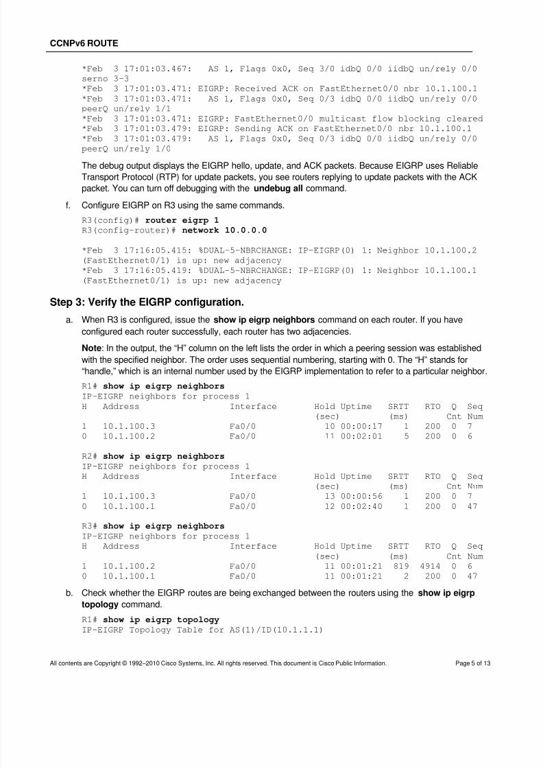
f. Configure EIGRP on R3 using the same commands.
R3(config)# router eigrp 1 R3(config-router)# network 10.0.0.0
*Feb 3 17:16:05.415: %DUAL-5-NBRCHANGE: IP-EIGRP(0) 1: Neighbor 10.1.100.2
(FastEthernet0/1) is up: new adjacency
*Feb 3 17:16:05.419: %DUAL-5-NBRCHANGE: IP-EIGRP(0) 1: Neighbor 10.1.100.1(FastEthernet0/1) is up: new adjacency
Step 3: Verify the EIGRP configuration.
a. When R3 is configured, issue the show ip eigrp neighbors command on each router. If you have
configured each router successfully, each router has two adjacencies.
Note: In the output, the “H” column on the left lists the order in which a peering session was established
with the specified neighbor. The order uses sequential numbering, starting with 0. The “H” stands for
“handle,” which is an internal number used by the EIGRP implementation to refer to a particular neighbor.
R1# show ip eigrp neighbors
IP-EIGRP neighbors for process 1
H Address Interface Hold Uptime SRTT RTO Q Seq(sec) (ms) Cnt Num
1 10.1.100.3 Fa0/0 10 00:00:17 1 200 0 7
0 10.1.100.2 Fa0/0 11 00:02:01 5 200 0 6
R2# show ip eigrp neighbors IP-EIGRP neighbors for process 1
H Address Interface Hold Uptime SRTT RTO Q Seq
(sec) (ms) Cnt Num
1 10.1.100.3 Fa0/0 13 00:00:56 1 200 0 7
0 10.1.100.1 Fa0/0 12 00:02:40 1 200 0 47
R3# show ip eigrp neighbors
IP-EIGRP neighbors for process 1H Address Interface Hold Uptime SRTT RTO Q Seq
(sec) (ms) Cnt Num
1 10.1.100.2 Fa0/0 11 00:01:21 819 4914 0 6
0 10.1.100.1 Fa0/0 11 00:01:21 2 200 0 47
b. Check whether the EIGRP routes are being exchanged between the routers using the show ip eigrp
topology command.
R1# show ip eigrp topology
IP-EIGRP Topology Table for AS(1)/ID(10.1.1.1)

8/6/2019 Ccnpv6 Route Lab2-1 Eigrp Config Student
http://slidepdf.com/reader/full/ccnpv6-route-lab2-1-eigrp-config-student 6/13
CCNPv6 ROUTE
All contents are Copyright © 1992–2010 Cisco Systems, Inc. All rights reserved. This document is Cisco Public Information. Page 6 of 13
Codes: P - Passive, A - Active, U - Update, Q - Query, R - Reply,
r - reply Status, s - sia Status
P 10.1.3.0/24, 1 successors, FD is 156160
via 10.1.100.3 (156160/128256), FastEthernet0/0
P 10.1.2.0/24, 1 successors, FD is 156160
via 10.1.100.2 (156160/128256), FastEthernet0/0
P 10.1.1.0/24, 1 successors, FD is 128256
via Connected, Loopback1
P 10.1.100.0/24, 1 successors, FD is 28160
via Connected, FastEthernet0/0
You should see all the networks currently advertised by EIGRP on every router. You will explore the
output of this command in the next lab. For now, verify that each loopback network exists in the EIGRP
topology table.
c. Because EIGRP is the only routing protocol running and currently has routes to these networks, issuing
the show ip route eigrp command displays the best route to the destination network.
R1# show ip route eigrp
10.0.0.0/24 is subnetted, 4 subnets
D 10.1.3.0 [90/156160] via 10.1.100.3, 00:00:53, FastEthernet0/0D 10.1.2.0 [90/156160] via 10.1.100.2, 00:00:53, FastEthernet0/0
d. To check whether you have full connectivity, ping the remote loopbacks from each router. If you have
successfully pinged all the remote loopbacks, congratulations! You have configured EIGRP to route
between these three remote networks.
Step 4: Configure EIGRP on the R1 and R2 serial interfaces.
a. Your serial interfaces are still in their default configuration. Specify the interface addresses according to
the diagram, and set the clock rate to 64 kb/s for R1.
R1(config)# interface serial 0/0/0 R1(config-if)# ip address 10.1.200.1 255.255.255.0
R1(config-if)# clock rate 64000 R1(config-if)# no shut
R2(config)# interface serial 0/0/0 R2(config-if)# ip address 10.1.200.2 255.255.255.0
R2(config-if)# no shut
Notice that even though you have clocked the interface at 64 kb/s, issuing the show interface serial
0/0/0 command reveals that the interface still shows the full T1 bandwidth of 1544 kb/s.
R1# show interfaces serial 0/0/0
Serial0/0/0 is up, line protocol is up
Hardware is GT96K Serial
Internet address is 10.1.200.1/24
MTU 1500 bytes, BW 1544 Kbit, DLY 20000 usec,reliability 255/255, txload 1/255, rxload 1/255
<output omitted>
The bandwidth is set primarily to provide the correct composite metric factor and a realistic and true
description of the available bandwidth on an interface. It is also set to prevent EIGRP from flooding the
interface. By default, EIGRP uses up to 50 percent of the bandwidth that the interface reports to the Cisco
IOS software. Suppose there was a significant routing instability in some other part of the EIGRP AS. If

8/6/2019 Ccnpv6 Route Lab2-1 Eigrp Config Student
http://slidepdf.com/reader/full/ccnpv6-route-lab2-1-eigrp-config-student 7/13
CCNPv6 ROUTE
All contents are Copyright © 1992–2010 Cisco Systems, Inc. All rights reserved. This document is Cisco Public Information. Page 7 of 13
EIGRP were to use 50 percent of 1544 kb/s for its own routing information traffic, EIGRP traffic would fully
saturate the low-bandwidth 64 kb/s serial link.
Recall that EIGRP uses a composite metric in which one of the variables is the bandwidth of the interface.
For EIGRP to make an accurate computation, it needs correct information about the bandwidth of the
serial link. Therefore, you must manually configure the bandwidth variable to 64 kb/s.
b. Apply the bandwidth 64 command to the R1 and R2 serial interfaces.
R1(config)# interface serial 0/0/0 R1(config-if)# bandwidth 64
R2(config)# interface serial 0/0/0 R2(config-if)# bandwidth 64
c. Verify that your bandwidth configuration is reflected in the output of the show interface serial 0/0/0
command.
R1# show interfaces serial 0/0/0
Serial0/0/0 is up, line protocol is up
Hardware is GT96K Serial
Internet address is 10.1.200.1/24MTU 1500 bytes, BW 64 Kbit, DLY 20000 usec,
reliability 255/255, txload 1/255, rxload 1/255
<output omitted>
R2# show interfaces serial 0/0/0
Serial0/0/0 is up, line protocol is up
Hardware is GT96K Serial
Internet address is 10.1.200.2/24
MTU 1500 bytes, BW 64 Kbit, DLY 20000 usec,
reliability 255/255, txload 1/255, rxload 1/255
<output omitted>
d. Issue the show ip eigrp neighbors command, which displays the following neighbor relationship
between R1 and R2.
R1# show ip eigrp neighbors
IP-EIGRP neighbors for process 1
H Address Interface Hold Uptime SRTT RTO Q Seq
(sec) (ms) Cnt Num
2 10.1.200.2 Se0/0/0 10 00:03:03 24 200 0 53
1 10.1.100.3 Fa0/0 14 09:22:42 269 1614 0 54
0 10.1.100.2 Fa0/0 11 09:22:42 212 1272 0 59
Step 5: Configure network statement wildcard masks.
a. On R3, create Loopback11 with IP address 192.168.100.1/30, and Loopback15 with IP address
192.168.100.5/30.
R3(config)# interface Loopback11 R3(config-if)# ip address 192.168.100.1 255.255.255.252 R3(config-if)# exit
R3(config)# interface Loopback15 R3(config-if)# ip address 192.168.100.5 255.255.255.252 R3(config-if)# exit

8/6/2019 Ccnpv6 Route Lab2-1 Eigrp Config Student
http://slidepdf.com/reader/full/ccnpv6-route-lab2-1-eigrp-config-student 8/13
CCNPv6 ROUTE
All contents are Copyright © 1992–2010 Cisco Systems, Inc. All rights reserved. This document is Cisco Public Information. Page 8 of 13
How can you add the 192.168.100.0/30 network to EIGRP without involving the 192.168.100.4/30
network as well?
_______________________________________________________________________________
_______________________________________________________________________________
_______________________________________________________________________________
_______________________________________________________________________________
In Step 2, you looked at how network statements select networks for routing using major network
boundaries. EIGRP also provides a way to select networks using wildcard masks. In a wildcard mask, bits
that can vary are denoted by 1s in the binary bit values. If you wanted to route both Loopback11 and
Loopback15 with EIGRP, you could use a wildcard mask that includes both of their network addresses,
such as network 192.168.100.0 0.0.0.7 or network 192.168.100.0 0.0.0.255. However, in this scenario,
you want to select only the IP network for Loopback11.
b. On R3, issue the following commands:
R3(config)# router eigrp 1
R3(config-router)# network 192.168.100.0 0.0.0.3
c. Did this solution work? Check it with the show ip eigrp interfaces command. Notice that Loopback11 is
involved in EIGRP, and Loopback15 is not.
R3# show ip eigrp interfaces
IP-EIGRP interfaces for process 1
Xmit Queue Mean Pacing Time Multicast
Pending
Interface Peers Un/Reliable SRTT Un/Reliable Flow Timer Routes
Fa0/0 2 0/0 5 0/1 50 0
Lo3 0 0/0 0 0/1 0 0Lo11 0 0/0 0 0/1 0 0
d. Which of these two IP networks can you see in the routing table on R1 after EIGRP converges with the
new network? Look at the output of the show ip route eigrp command on R1.
R1# show ip route eigrp
10.0.0.0/24 is subnetted, 5 subnets
D 10.1.3.0 [90/156160] via 10.1.100.3, 00:05:59, FastEthernet0/0
D 10.1.2.0 [90/156160] via 10.1.100.2, 00:12:16, FastEthernet0/0
D 192.168.100.0/24 [90/156160] via 10.1.100.3, 00:03:05, FastEthernet0/0
Notice that the subnet mask for the 192.168.100.0 network advertised by R3 is 24 bits. This will be
examined more fully in the next lab. Which configuration command would allow R3 to advertise the proper
subnet mask to its adjacent routers?
_______________________________________________________________________________
e. On R3, issue the show ip protocols command. Notice that automatic summarization is in effect. Also
note the networks for which it is routing.
R3# show ip protocols
Routing Protocol is "eigrp 1"
Outgoing update filter list for all interfaces is not set
Incoming update filter list for all interfaces is not set

8/6/2019 Ccnpv6 Route Lab2-1 Eigrp Config Student
http://slidepdf.com/reader/full/ccnpv6-route-lab2-1-eigrp-config-student 9/13
CCNPv6 ROUTE
All contents are Copyright © 1992–2010 Cisco Systems, Inc. All rights reserved. This document is Cisco Public Information. Page 9 of 13
Default networks flagged in outgoing updates
Default networks accepted from incoming updates
EIGRP metric weight K1=1, K2=0, K3=1, K4=0, K5=0
EIGRP maximum hopcount 100
EIGRP maximum metric variance 1
Redistributing: eigrp 1
EIGRP NSF-aware route hold timer is 240s
Automatic network summarization is in effect
Automatic address summarization:
192.168.100.0/24 for Loopback11
Summarizing with metric 128256
10.0.0.0/8 for Loopback3, FastEthernet0/0
Summarizing with metric 28160
Maximum path: 4
Routing for Networks:
10.0.0.0
192.168.100.0/30
Routing Information Sources:
Gateway Distance Last Update
(this router) 90 00:22:13
Gateway Distance Last Update10.1.100.2 90 00:22:15
10.1.100.1 90 00:22:15
Distance: internal 90 external 170
Challenge: Topology Change
You have been reading up about the advantages of different routing protocols. You noticed statements
claiming that EIGRP converges faster than other routing protocols in a topology where there are multiple
paths to the destination network. You are interested in testing this before you bring the network that you are
designing online.
Verify the neighbor relationships and that the routing table of each router has the original loopback interfaces
of the other routers, as described in the initial diagram. Make sure that you issue the debug ip eigrpcommand on all routers.
a. Issue the show ip route command on R2 and R3.
R2# show ip route eigrp
10.0.0.0/24 is subnetted, 5 subnets
D 10.1.3.0 [90/156160] via 10.1.100.3, 00:05:22, FastEthernet0/0
D 10.1.1.0 [90/156160] via 10.1.100.1, 00:05:22, FastEthernet0/0
D 192.168.100.0/24 [90/156160] via 10.1.100.3, 00:14:30, FastEthernet0/0
R3# show ip route eigrp
10.0.0.0/24 is subnetted, 5 subnets
D 10.1.2.0 [90/156160] via 10.1.100.2, 09:25:37, FastEthernet0/0
D 10.1.1.0 [90/156160] via 10.1.100.1, 09:25:37, FastEthernet0/0
D 10.0.0.0/8 is a summary, 09:25:37, Null0
D 10.1.200.0 [90/40514560] via 10.1.100.2, 00:03:01, FastEthernet0/0
[90/40514560] via 10.1.100.1, 00:03:01, FastEthernet0/0
192.168.100.0/24 is variably subnetted, 3 subnets, 2 masks
D 192.168.100.0/24 is a summary, 00:18:15, Null0
b. From R3, trace the route to the Lo1 IP address on R1.
R3# traceroute 10.1.1.1
Type escape sequence to abort.

8/6/2019 Ccnpv6 Route Lab2-1 Eigrp Config Student
http://slidepdf.com/reader/full/ccnpv6-route-lab2-1-eigrp-config-student 10/13
CCNPv6 ROUTE
All contents are Copyright © 1992–2010 Cisco Systems, Inc. All rights reserved. This document is Cisco Public Information. Page 10 of 13
Tracing the route to 10.1.1.1
1 10.1.100.1 4 msec * 0 msec
R3 is using R1 as the next hop to get to destination network 10.1.1.0/24 per the R3 routing table.
However, R3 could potentially get to R1 through R2 via the serial link if the Fa0/0 interface on R1 was
shut down.
c. From R3, issue a ping with a high repeat count to the destination address 10.1.1.1. You should see
multiple exclamation points flooding the console output from R3.
R3# ping 10.1.1.1 repeat 10000
d. While the extended ping on R3 is running, shut down the Fa0/0 interface on R1. Allow the pings on R3 to
complete.
R1(config)# interface FastEthernet0/0 R1(config-if)# shutdown
Type escape sequence to abort.
Sending 10000, 100-byte ICMP Echos to 10.1.1.1, timeout is 2 seconds:!!!!!!!!!!!!!!!!!!!!!!!!!!!!!!!!!!!!!!!!!!!!!!!!!!!!!!!!!!!!!!!!!!!!!!
!!!!!!!!!!!!!!!!!!!!!!!!!!!!!!!!!!!!!!!!!!!!!!!!!!!!!!!!!!!!!!!!!!!!!!
!!!!!!!!!!!!!!!!!!!!!!!!!!!!!!!!!!!!!!!!!!!!!!!!!!!!!!!!!!!!!!!!!!!!!!
!!!!!!!!!!!!!!!!!!!!!!!!!!!!!!!!!!!!!!!!!!!!!!!!!!!!!!!!!!!!!!!!!!!!!!
!!!!!!!!!!!!!!!!!!!!!!!!!!!!!!!!!!!!!!!!!!!!!!!!!!!!!!!!!!!!!!!!!!!!!!
!!!!!!!!!!!!!!!!!!!!!!!!!!!!!!!!!!!!!!!!!!!!!!!!!!!!!!!!!!!!!!!!!!!!!!
!!!!!!!!!!!!!!!!!!!!!!!!!!!!!!!!!!!!!!!!!!!!!!!!!!!!!!!!!!!!!!!!!!!!!!
!!!!!!!!!!!!!!!!!!!!!!!!!!!!!!!!!!!!!!!!!!!!!!!!!!!!!!!!!!!!!!!!!!!!!!
!!!!!!!!!!!!!!!!!!!!!!!!!!!!!!!!!!!!!!!!!!!!!!!!!!!!!!!!!!!!!!!!!!!!!!
!!!!!!!!!!!!!!!!!!!!!!!!!!!!!!!!!!!!!!!!!!!!!!!!!!!!!!!!!!!!!!!!!!!!!!
!!!!!!!!!!!!!!!!!!!!!!!!!!!!!!!!!!!!!!!!!!!!!!!!!!!!!!!!!!!!!!!!!!!!!!
!!!!!!!!!!!!!!!!!!!!!!!!!!!!!!!!!!!!!!!!!!!!!!!!!!!!!!!!!!!!!!!!!!!!!!
!!!!!!!!!!!!!!!!!!!!!!!!!!!!!!!!!!!!!!!!!!!!!!!!!!!!!!!!!!!!!!!!!!!!!!
!!!!!!!!!!!!!!!!!!!!!!!!!!!!!!!!!.......!!!!!!!!!!!!!!!!!!!!!!!!!!!!!!
*Feb 4 13:35:55.311: %DUAL-5-NBRCHANGE: IP-EIGRP(0) 1: Neighbor 10.1.100.1
(FastEthernet0/0) is down: holding time expired
<output omitted>
!!!!!!!!!!!!!!!!!!!!!!!!!!!!!!!!!!!!!!!!!!!!!!!!!!!!!!!!!!!!!!!!!!!!!!
!!!!!!!!!!!!!!!!!!!!!!!!!!!!!!!!!!!!!!!!!!!!!!!!!!!!!!!!!!!!!!!!!!!!!!
Success rate is 99 percent (9992/10000), round-trip min/avg/max = 1/16/68 ms
From the perspective of R3, how many packets were dropped?
_______________________________________________________________________________
_______________________________________________________________________________
_______________________________________________________________________________
Which of the EIGRP timers causes this delay in the route recalculation?
_______________________________________________________________________________

8/6/2019 Ccnpv6 Route Lab2-1 Eigrp Config Student
http://slidepdf.com/reader/full/ccnpv6-route-lab2-1-eigrp-config-student 11/13
CCNPv6 ROUTE
All contents are Copyright © 1992–2010 Cisco Systems, Inc. All rights reserved. This document is Cisco Public Information. Page 11 of 13
e. Use the traceroute command to find the new route from R3 to R1.
R3# traceroute 10.1.1.1
Type escape sequence to abort.
Tracing the route to 10.1.1.1
1 10.1.100.2 0 msec 0 msec 0 msec2 10.1.200.1 16 msec 12 msec *
f. Start the repeated ping again from R3, and administratively bring up the Fa0/0 interface on R1.
R3# ping 10.1.1.1 repeat 10000
R1(config)# interface FastEthernet0/0 R1(config-if)# no shutdown
!!!!!!!!!!!!!!!!!!!!!!!!!!!!!!!!!!!!!!!!!!!!!!!!!!!!!!!!!!!!!!!!!!!!!!
!!!!!!!!!!!!!!!!!!!!!!!!!!!!!!!!!!!!!!!!!!!!!!!!!!!!!!!!!!!!!!!!!!!!!!
!!!!!!!!!!!!!!!!!!!!!!!!!!!!!!!!!!!!!!!!!!!!!!!!!!!!!!!!!!!!!!!!!!!!!!
!!!!!!!!!!!!!!!!!!!!!!!!!!!!!!!!!!!!!!!!!!!!!!!!!!!!!!!!!!!!!!!!!!!!!!
!!!!!!!!!!!!!!!!!!!!!!!!!!!!!!!!!!!!!!!!!!!!!!!!!!!!!!!!!!!!!!!!!!!!!!!!!!!!!!!!!!!!!!!!!!!!!!!!!!!!!!!!!!!!!!!!!!!!!!!!!!!!!!!!!!!!!!!!!!!!
!!!!!!!!!!!!!!!!!!!!!!!!!!!!!!!!!!!!!!!!!!!!!!!!!!!!!!!!............!!
*Feb 4 13:35:55.147: %DUAL-5-NBRCHANGE: IP-EIGRP(0) 1: Neighbor 10.1.100.1
(FastEthernet0/0) is up: new adjacency!!!!!!!!!!!!!!!!!!!!!!!!!!!!!!!!
!!!!!!!!!!!!!!!!!!!!!!!!!!!!!!!!!!!!!!!!!!!!!!!!!!!!!!!!!!!!!!!!!!!!!!
<output omitted>
Success rate is 99 percent (9983/10000), round-trip min/avg/max = 1/2/44 ms
From the perspective of R3, how many packets were dropped?
_______________________________________________________________________________ _______________________________________________________________________________
Note: The loss ICMP ECHO packets results in a significant delay, as many as 30 or more seconds. Why
did it take so long for R3 to reestablish ping connectivity with R3 after the R1 Fa0/0 interface was re-
enabled and what changes could be made to correct the problem? The answer lies with the switch itself.
The switch that connects the three routers together is in its default configuration, running STP on each
port and requiring 30 seconds to proceed through Listening and Learning states until a port transitions to
the Forwarding state. The 17 lost packets are caused by the 30 seconds required by STP to transition the
port to Forwarding state plus a couple of seconds for DTP to determine the port mode and perhaps ARP
to resolve R3's MAC address.
This issue can be addressed by configuring the switch with the spanning-tree portfast default
command. In addition, all ports could be defined as static access ports using the switchport mode
access command.

8/6/2019 Ccnpv6 Route Lab2-1 Eigrp Config Student
http://slidepdf.com/reader/full/ccnpv6-route-lab2-1-eigrp-config-student 12/13
CCNPv6 ROUTE
All contents are Copyright © 1992–2010 Cisco Systems, Inc. All rights reserved. This document is Cisco Public Information. Page 12 of 13
If you were using RIPv2 as your routing protocol instead of EIGRP, would fewer or more packets be
dropped?
_______________________________________________________________________________
_______________________________________________________________________________
_______________________________________________________________________________ _______________________________________________________________________________

8/6/2019 Ccnpv6 Route Lab2-1 Eigrp Config Student
http://slidepdf.com/reader/full/ccnpv6-route-lab2-1-eigrp-config-student 13/13
CCNPv6 ROUTE
All contents are Copyright © 1992–2010 Cisco Systems, Inc. All rights reserved. This document is Cisco Public Information. Page 13 of 13
Router Interface Summary Table
Router Interface Summary
Router Model Ethernet Interface#1
Ethernet Interface#2
Serial Interface#1
Serial Interface#2
1700 Fast Ethernet 0(FA0)
Fast Ethernet 1(FA1)
Serial 0 (S0) Serial 1 (S1)
1800 Fast Ethernet 0/0(FA0/0)
Fast Ethernet 0/1(FA0/1)
Serial 0/0/0(S0/0/0)
Serial 0/0/1(S0/0/1)
2600 Fast Ethernet 0/0(FA0/0)
Fast Ethernet 0/1(FA0/1)
Serial 0/0 (S0/0) Serial 0/1 (S0/1)
2800 Fast Ethernet 0/0(FA0/0)
Fast Ethernet 0/1(FA0/1)
Serial 0/0/0(S0/0/0)
Serial 0/0/1(S0/0/1)
Note: To find out how the router is configured, look at the interfaces to identify the type of routerand how many interfaces the router has. Rather than list all combinations of configurations for eachrouter class, this table includes identifiers for the possible combinations of Ethernet and serialinterfaces in the device. The table does not include any other type of interface, even though a
specific router might contain one. For example, for an ISDN BRI interface, the string in parenthesisis the legal abbreviation that can be used in Cisco IOS commands to represent the interface.