CCNP SWITCH 642-813 Quick Reference -...
112
CCNP SWITCH 642-813 Quick Reference Chapter 1: Campus Network Design........................4 Chapter 2: VLAN Implementation ...........................12 Chapter 3: Spanning Tree ........................................29 Chapter 4: InterVLAN Routing ................................49 Chapter 5: Implementing High Availability ............59 Chapter 6: First Hop Redundancy ..........................72 Chapter 7: Campus Network Security...................79 Chapter 8: Voice and Video in a Campus Network ...........................91 Chapter 9: Wireless LANs in a Campus Network .........................102 Denise Donohue ciscopress.com
Transcript of CCNP SWITCH 642-813 Quick Reference -...
CCNP SWITCH 642-813Quick Reference
Chapter 1:Campus Network Design........................4
Chapter 2:VLAN Implementation...........................12
Chapter 3:Spanning Tree........................................29
Chapter 4:InterVLAN Routing ................................49
Chapter 5:Implementing High Availability............59
Chapter 6:First Hop Redundancy ..........................72
Chapter 7:Campus Network Security...................79
Chapter 8:Voice and Video in a Campus Network ...........................91
Chapter 9:Wireless LANs in a Campus Network.........................102
Denise Donohue
ciscopress.com
9781587140112.qxd 11/23/09 11:34 AM Page 1
About the AuthorDenise Donohue, CCIE No. 9566, is a senior solutions architect for ePlus Technology. She consults with companies todesign updates or additions to their data and VOIP networks. Prior to this role, she was a systems engineer for the dataconsulting arm of SBC/AT&T. Denise has been a Cisco instructor and course director for Global Knowledge and didnetwork consulting for many years. Her CCIE is in Routing and Switching.
About the Technical Editor‘Rhette (Margaret) Marsh has been working in the networking and security industry for more than ten years, and hasextensive experience with internetwork design, IPv6, forensics, and greyhat work. She currently is a design consultant forCisco in San Jose, CA, and works primarily with the Department of Defense and contractors. Prior to this, she workedextensively both in the financial industry as a routing and switching and design/security consultant and also in an attackattribution and forensics context. She currently holds a CCIE in Routing and Switching (No. 17476), CCNP, CCDP,CCNA, CCDA, CISSP and is working towards her Security and Design CCIEs. In her copious free time, she enjoysnumber theory, arcane literature, cycling, hiking in the redwoods, sea kayaking, and her mellow cat, Lexx.
[ 2 ]
© 2010 Pearson Education, Inc. All rights reserved. This publication is protected by copyright. Please see page 112 for more details.
CCNP SWITCH 642-813 Quick Reference by Denise Donohue
9781587140112.qxd 11/23/09 11:34 AM Page 2
Icons Used
[ 3 ]
© 2010 Pearson Education, Inc. All rights reserved. This publication is protected by copyright. Please see page 112 for more details.
CCNP SWITCH 642-813 Quick Reference by Denise Donohue
Router PCMultilayerSwitch
Route/Switch Processor
Workgroup Switch
9781587140112.qxd 11/23/09 11:34 AM Page 3
CHAPTER 1
Campus Network Design
Chapter 1Campus Network Design
An enterprise campus generally refers to a network in a specific geographic location. It can be within one building orspan multiple buildings near each other. A campus network also includes the Ethernet LAN portions of a network outsidethe data center. Large enterprises have multiple campuses connected by a WAN. Using models to describe the networkarchitecture divides the campus into several internetworking functional areas, thus simplifying design, implementation,and troubleshooting.
The Hierarchical Design ModelCisco has used the three-level Hierarchical Design Model for years. The hierarchical design model divides a network intothree layers:
n Access: Provides end-user access to the network. In the LAN, local devices such as phones and computers accessthe local network. In the WAN, remote users or sites access the corporate network.
n High availability via hardware such as redundant power supplies and redundant supervisor engines. Softwareredundancy via access to redundant default gateways using a first hop redundancy protocol (FHRP).
n Converged network support by providing access to IP phones, computers, and wireless access points. ProvidesQoS and multicast support.
n Security through switching tools such as Dynamic ARP Inspection, DHCP snooping, BPDU Guard, port-security,and IP source guard. Controls network access.
[ 4 ]
© 2010 Pearson Education, Inc. All rights reserved. This publication is protected by copyright. Please see page 112 for more details.
CCNP SWITCH 642-813 Quick Reference by Denise Donohue
9781587140112.qxd 11/23/09 11:34 AM Page 4
CHAPTER 1
Campus Network Design
n Distribution: Aggregation point for access switches. Provides availability, QoS, fast path recovery, and load balancing.
n High availability through redundant distribution layer switches providing dual paths to the access switches and tocore switches. Use of FHRP protocols to ensure connectivity if one distribution switch is removed.
n Routing policies applied, such as route selection, filtering, and summarization. Can be default gateway for accessdevices. QoS and security policies applied.
n Segmentation and isolation of workgroups and workgroup problems from the core, typically using a combinationof Layer 2 and Layer 3 switching.
n Core: The backbone that provides a high-speed, Layer 3 path between distribution layers and other networksegments. Provides reliability and scalability.
n Reliability through redundant devices, device components, and paths.
n Scalability through scalable routing protocols. Having a core layer in general aids network scalability by provid-ing gigabit (and faster) connectivity, data and voice integration, and convergence of the LAN, WAN, and MAN.
n No policies such as ACLs or filters that would slow traffic down.
A set of distribution devices and their accompanying access layer switches are called a switch block.
The Core LayerIs a core layer always needed? Without a core layer, the distribution switches must be fully meshed. This becomes moreof a problem as a campus network grows larger. A general rule is to add a core when connecting three or more buildingsor four or more pairs of building distribution switches. Some benefits of a campus core are:
n Adds a hierarchy to distribution switch connectivity
n Simplifies cabling because a full-mesh between distribution switches is not required
n Reduces routing complexity by summarizing distribution networks
[ 5 ]
© 2010 Pearson Education, Inc. All rights reserved. This publication is protected by copyright. Please see page 112 for more details.
CCNP SWITCH 642-813 Quick Reference by Denise Donohue
9781587140112.qxd 11/23/09 11:34 AM Page 5
CHAPTER 1
Campus Network Design
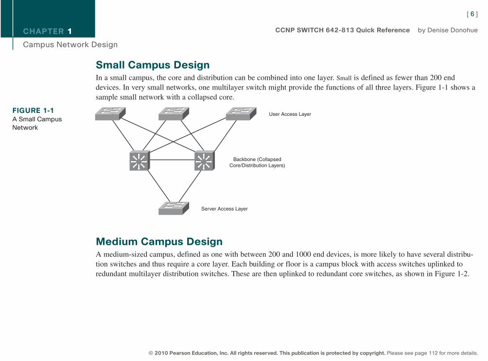
Small Campus DesignIn a small campus, the core and distribution can be combined into one layer. Small is defined as fewer than 200 enddevices. In very small networks, one multilayer switch might provide the functions of all three layers. Figure 1-1 shows asample small network with a collapsed core.
Medium Campus DesignA medium-sized campus, defined as one with between 200 and 1000 end devices, is more likely to have several distribu-tion switches and thus require a core layer. Each building or floor is a campus block with access switches uplinked toredundant multilayer distribution switches. These are then uplinked to redundant core switches, as shown in Figure 1-2.
[ 6 ]
© 2010 Pearson Education, Inc. All rights reserved. This publication is protected by copyright. Please see page 112 for more details.
CCNP SWITCH 642-813 Quick Reference by Denise Donohue
FIGURE 1-1A Small Campus
Network
User Access Layer
Backbone (CollapsedCore/Distribution Layers)
Server Access Layer
9781587140112.qxd 11/23/09 11:34 AM Page 6

CHAPTER 1
Campus Network Design
Data Center DesignThe core layer connects end users to the data center devices. The data center segment of a campus can vary in size fromfew servers connected to the same switch as users in a small campus, to a separate network with its own three-layerdesign in a large enterprise. The three layers of a data center model are slightly different:
n Core layer: Connects to the campus core. Provides fast switching for traffic into and out of the data center.
n Aggregation layer: Provides services such as server load balancing, content switching, SSL off-load, and securitythrough firewalls and IPS.
n Access layer: Provides access to the network for servers and storage units. Can be either Layer 2 or Layer 3switches.
[ 7 ]
© 2010 Pearson Education, Inc. All rights reserved. This publication is protected by copyright. Please see page 112 for more details.
CCNP SWITCH 642-813 Quick Reference by Denise Donohue
FIGURE 1-2A Medium-Sized
Campus Network
Building Access Layer
BuildingDistribution
Layer
Building Access Layer
BuildingDistribution
Layer
Data Center
Core Layer
9781587140112.qxd 11/23/09 11:34 AM Page 7
CHAPTER 1
Campus Network Design
Network Traffic FlowThe need for a core layer and the devices chosen for the core also depend on the type of network traffic and traffic flowpatterns. Modern converged networks include different traffic types, each with unique requirements for security, QoS,transmission capacity, and delay. These include:
n IP telephony signaling and media
n Core Application traffic, such as Enterprise Resource Programming (ERP), Customer Relationship Management(CRM)
n Multicast multimedia
n Network management
n Application data traffic, such as web pages, email, file transfer, and database transactions
n Scavenger class traffic that requires less-than-best-effort treatment
The different types of applications also have different traffic flow patterns. These might include:
n Peer-to-Peer applications such as IP phone calls, video conferencing, file sharing, and instant messaging providesreal-time interaction. It might not traverse the core at all, if the users are local to each other. Their network require-ments vary, with voice having strict jitter needs and video conferencing using high bandwidth.
n Client-Server applications require access to servers such as email, file storage, and database servers. These serversare typically centralized in a data center, and users require fast, reliable access to them. Server farm access must alsobe securely controlled to deny unauthorized users.
[ 8 ]
© 2010 Pearson Education, Inc. All rights reserved. This publication is protected by copyright. Please see page 112 for more details.
CCNP SWITCH 642-813 Quick Reference by Denise Donohue
9781587140112.qxd 11/23/09 11:34 AM Page 8
CHAPTER 1
Campus Network Design
n Client-Enterprise Edge applications are located on servers at the WAN edge, reachable from outside the company.These can include email and web servers, or e-commerce servers, for example. Access to these servers must besecure and highly available.
Service-Oriented Network ArchitectureService-Oriented Network Architecture (SONA) attempts to provide a design framework for a network that can deliverthe services and applications businesses need. It acknowledges that the network connects all components of the businessand is critical to them. The SONA model integrates network and application functionality cooperatively and enables thenetwork to be smart about how it handles traffic to minimize the footprint of applications.
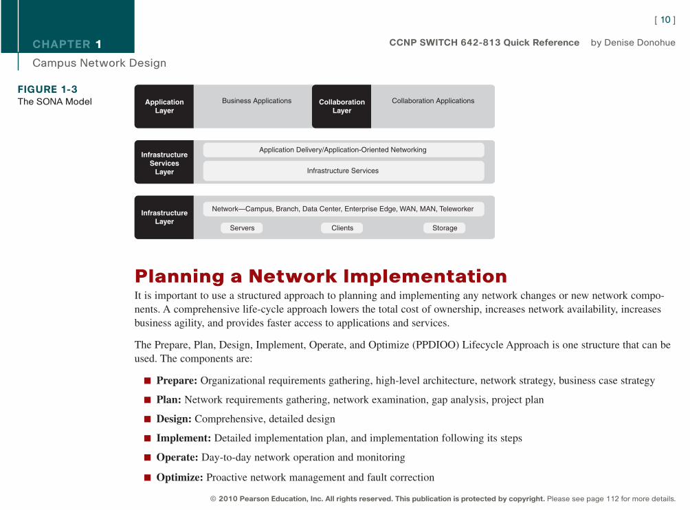
Figure 1-3 shows how SONA breaks down this functionality into three layers:
n Network Infrastructure: Campus, data center, branch, and so on. Networks and their attached end systems(resources such as servers, clients, and storage.) These can be connected anywhere within the network. The goal is toprovide anytime/any place connectivity.
n Interactive Services: Resources allocated to applications, using the network infrastructure. These include:
n Management
n Infrastructure services such as security, mobility, voice, compute, storage, and identity
n Application delivery
n Virtualization of services and network infrastructure
n Applications: Includes business policy and logic. Leverages the interactive services layer to meet business needs.Has two sublayers:
n Application layer, which defines business applications
n Collaboration layer, which defines applications such as unified messaging, conferencing, IP telephony, video,instant messaging, and contact centers
[ 9 ]
© 2010 Pearson Education, Inc. All rights reserved. This publication is protected by copyright. Please see page 112 for more details.
CCNP SWITCH 642-813 Quick Reference by Denise Donohue
9781587140112.qxd 11/23/09 11:34 AM Page 9
CHAPTER 1
Campus Network Design
Planning a Network ImplementationIt is important to use a structured approach to planning and implementing any network changes or new network compo-nents. A comprehensive life-cycle approach lowers the total cost of ownership, increases network availability, increasesbusiness agility, and provides faster access to applications and services.
The Prepare, Plan, Design, Implement, Operate, and Optimize (PPDIOO) Lifecycle Approach is one structure that can beused. The components are:
n Prepare: Organizational requirements gathering, high-level architecture, network strategy, business case strategy
n Plan: Network requirements gathering, network examination, gap analysis, project plan
n Design: Comprehensive, detailed design
n Implement: Detailed implementation plan, and implementation following its steps
n Operate: Day-to-day network operation and monitoring
n Optimize: Proactive network management and fault correction
[ 10 ]
© 2010 Pearson Education, Inc. All rights reserved. This publication is protected by copyright. Please see page 112 for more details.
CCNP SWITCH 642-813 Quick Reference by Denise Donohue
FIGURE 1-3The SONA Model
InfrastructureLayer
Network—Campus, Branch, Data Center, Enterprise Edge, WAN, MAN, Teleworker
Servers StorageClients
InfrastructureServices
Layer
Application Delivery/Application-Oriented Networking
Infrastructure Services
ApplicationLayer
CollaborationLayer
Business Applications Collaboration Applications
9781587140112.qxd 11/23/09 11:34 AM Page 10
CHAPTER 1
Campus Network Design
Network engineers at the CCNP level will likely be involved at the implementation and following phases. They can alsoparticipate in the design phase. It is important to create a detailed implementation plan that includes test and verificationprocedures and a rollback plan. Each step in the implementation plan should include a description, a reference to thedesign document, detailed implementation and verification instructions, detailed rollback instructions, and the estimatedtime needed for completion. A complex implementation should be done in sections, with testing at each incrementalsection.
[ 11 ]
© 2010 Pearson Education, Inc. All rights reserved. This publication is protected by copyright. Please see page 112 for more details.
CCNP SWITCH 642-813 Quick Reference by Denise Donohue
9781587140112.qxd 11/23/09 11:34 AM Page 11
CHAPTER 2
VLAN Implementation
Chapter 2VLAN Implementation
VLANs are used to break large campus networks into smaller pieces. The benefit of this is to minimize the amount ofbroadcast traffic on a logical segment.
VLAN OverviewA virtual LAN (VLAN) is a logical LAN, or a logical subnet. It defines a broadcast domain. A physical subnet is a groupof devices that shares the same physical wire. A logical subnet is a group of switch ports assigned to the same VLAN,regardless of their physical location in a switched network. VLAN membership can be assigned either statically by port,or dynamically by MAC address or username.
Two types of VLANs are:
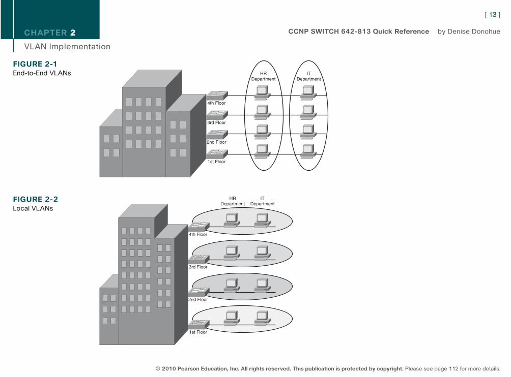
n End-to-end VLAN: VLAN members reside on different switches throughout the network. They are used when hostsare assigned to VLANs for policy reasons, rather than physical location. This provides users a consistent policy andaccess to resources regardless of their location. It also makes troubleshooting more complex because so manyswitches can carry traffic for a specific VLAN, and broadcasts can traverse many switches. Figure 2-1 shows end-to-end VLANs.
n Local VLAN: Hosts are assigned to VLANs based on their location, such as a floor in a building. This design is more scalable and easier to troubleshoot because the traffic flow is more deterministic. It enablesmore redundancy and minimizes failure domains. It does require a routing function to share resources betweenVLANs. Figure 2-2 shows an example of local VLANs.
[ 12 ]
© 2010 Pearson Education, Inc. All rights reserved. This publication is protected by copyright. Please see page 112 for more details.
CCNP SWITCH 642-813 Quick Reference by Denise Donohue
9781587140112.qxd 11/23/09 11:34 AM Page 12
CHAPTER 2
VLAN Implementation
[ 13 ]
© 2010 Pearson Education, Inc. All rights reserved. This publication is protected by copyright. Please see page 112 for more details.
CCNP SWITCH 642-813 Quick Reference by Denise Donohue
FIGURE 2-1End-to-End VLANs
4th Floor
HRDepartment
ITDepartment
3rd Floor
2nd Floor
1st Floor
FIGURE 2-2Local VLANs
4th Floor
HRDepartment
ITDepartment
3rd Floor
2nd Floor
1st Floor
9781587140112.qxd 11/23/09 11:34 AM Page 13

CHAPTER 2
VLAN Implementation
When planning a VLAN structure, consider traffic flows and link sizing. Take into account the entire traffic pattern ofapplications found in your network. For instance, IP voice media traffic travels directly between phones, but signalingtraffic must pass to the Unified Communications Manager. Multicast traffic must communicate back to the routingprocess and possibly call upon a Rendezvous Point. Various user applications, such as email and Citrix, place differentdemands on the network.
Application flow influences link bandwidth. Remember that uplink ports need to handle all hosts communicating concur-rently, and although VLANs logically separate traffic, traffic in different VLANs still travels over the same trunk line.Benchmark throughput for critical application and user data during peak hours; then analyze the results for any bottle-necks throughout the layered design.
User access ports are typically Fast Ethernet or faster. Access switches must have the necessary port density and can beeither Layer 2 or Layer 3. Ports from user Access to the Distribution layer should be Gigabit Ethernet or better, with anoversubscription ratio of no more than 20:1. Distribution switches should be multilayer or Layer 3. Links from Distributionto the Core should be Gigabit Etherchannel or 10-Gig Ethernet, with an oversubscription of no more than 4:1.
VLAN PlanningBefore beginning a VLAN implementation, you need to determine the following information:
n VLAN numbering, naming and IP addressing scheme
n VLAN placement—local or multiple switches
n Are any trunks necessary and where?
n VTP parameters
n Test and verification plan
[ 14 ]
© 2010 Pearson Education, Inc. All rights reserved. This publication is protected by copyright. Please see page 112 for more details.
CCNP SWITCH 642-813 Quick Reference by Denise Donohue
9781587140112.qxd 11/23/09 11:34 AM Page 14
CHAPTER 2
VLAN Implementation
Creating a VLAN and Assigning PortsVLANs must be created before they can be used. Creating VLANs is easy—in global configuration mode just identify theVLAN number and optionally name it!
(config)# vlan 12
(config-vlan)# name MYVLAN
Delete a VLAN by using the same command with no in front of it. There is no need to include the name when deleting.
When statically assigning ports to VLANs, first make the interface an access port, and then assign the port to a VLAN. Atthe interface configuration prompt:
(config-if)# switchport mode access
(config-if)# switchport access vlan 12
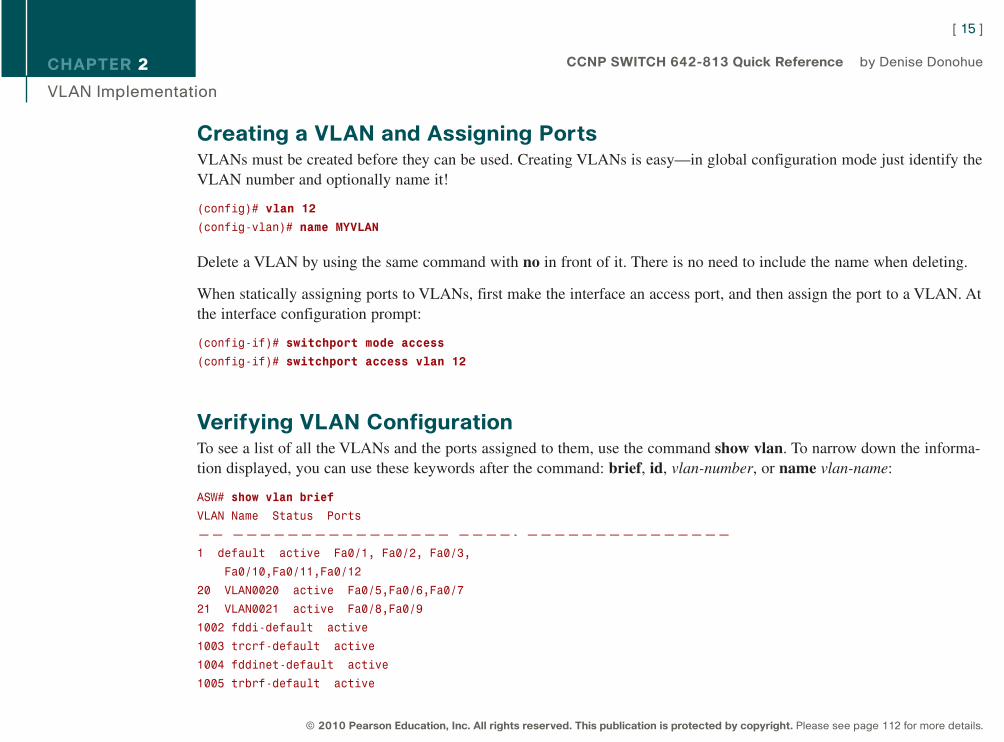
Verifying VLAN ConfigurationTo see a list of all the VLANs and the ports assigned to them, use the command show vlan. To narrow down the informa-tion displayed, you can use these keywords after the command: brief, id, vlan-number, or name vlan-name:
ASW# show vlan brief
VLAN Name Status Ports
—— ———————————————— ————- ———————————————
1 default active Fa0/1, Fa0/2, Fa0/3,
Fa0/10,Fa0/11,Fa0/12
20 VLAN0020 active Fa0/5,Fa0/6,Fa0/7
21 VLAN0021 active Fa0/8,Fa0/9
1002 fddi-default active
1003 trcrf-default active
1004 fddinet-default active
1005 trbrf-default active
[ 15 ]
© 2010 Pearson Education, Inc. All rights reserved. This publication is protected by copyright. Please see page 112 for more details.
CCNP SWITCH 642-813 Quick Reference by Denise Donohue
9781587140112.qxd 11/23/09 11:34 AM Page 15
CHAPTER 2
VLAN Implementation
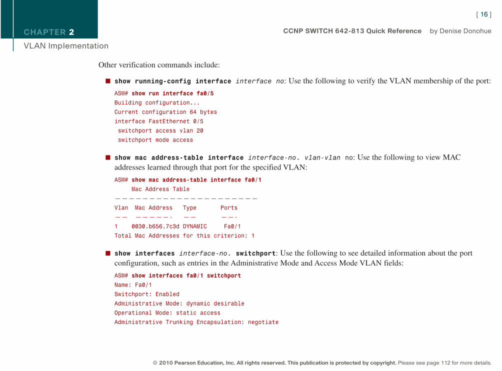
Other verification commands include:
n show running-config interface interface no: Use the following to verify the VLAN membership of the port:
ASW# show run interface fa0/5
Building configuration...
Current configuration 64 bytes
interface FastEthernet 0/5
switchport access vlan 20
switchport mode access
n show mac address-table interface interface-no. vlan-vlan no: Use the following to view MACaddresses learned through that port for the specified VLAN:
ASW# show mac address-table interface fa0/1
Mac Address Table
—————————————————————
Vlan Mac Address Type Ports
—— —————- —— ——-
1 0030.b656.7c3d DYNAMIC Fa0/1
Total Mac Addresses for this criterion: 1
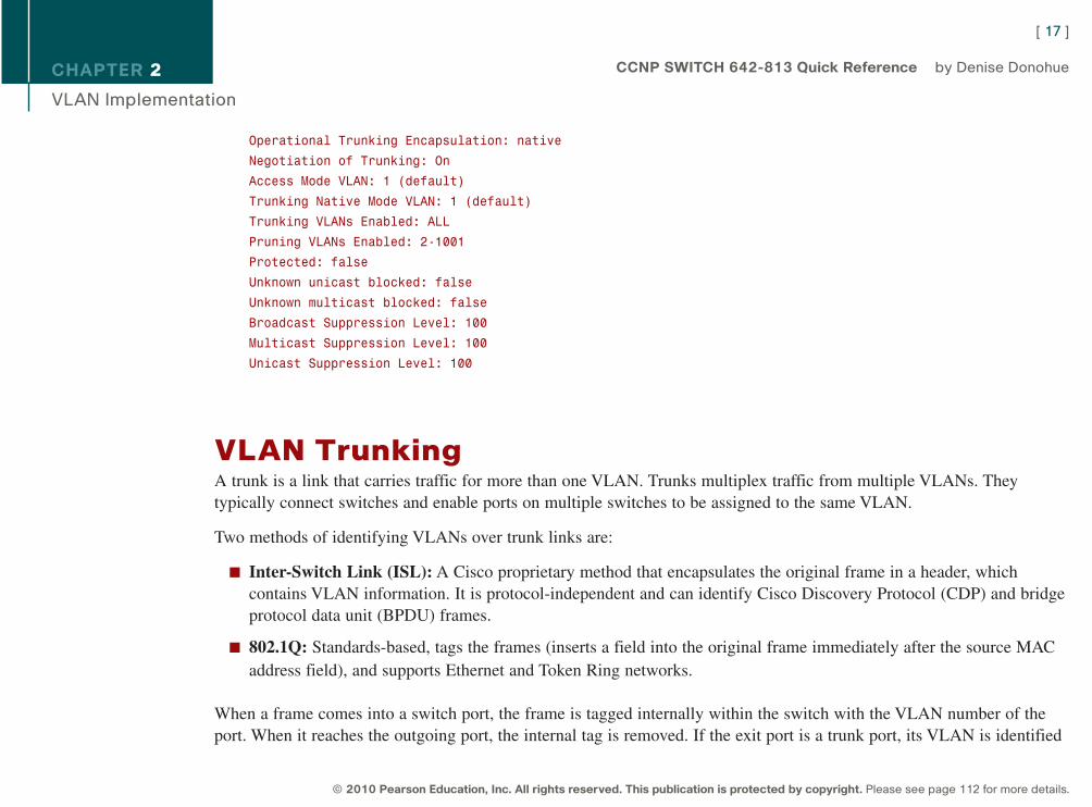
n show interfaces interface-no. switchport: Use the following to see detailed information about the portconfiguration, such as entries in the Administrative Mode and Access Mode VLAN fields:
ASW# show interfaces fa0/1 switchport
Name: Fa0/1
Switchport: Enabled
Administrative Mode: dynamic desirable
Operational Mode: static access
Administrative Trunking Encapsulation: negotiate
[ 16 ]
© 2010 Pearson Education, Inc. All rights reserved. This publication is protected by copyright. Please see page 112 for more details.
CCNP SWITCH 642-813 Quick Reference by Denise Donohue
9781587140112.qxd 11/23/09 11:34 AM Page 16
CHAPTER 2
VLAN Implementation
Operational Trunking Encapsulation: native
Negotiation of Trunking: On
Access Mode VLAN: 1 (default)
Trunking Native Mode VLAN: 1 (default)
Trunking VLANs Enabled: ALL
Pruning VLANs Enabled: 2-1001
Protected: false
Unknown unicast blocked: false
Unknown multicast blocked: false
Broadcast Suppression Level: 100
Multicast Suppression Level: 100
Unicast Suppression Level: 100
VLAN TrunkingA trunk is a link that carries traffic for more than one VLAN. Trunks multiplex traffic from multiple VLANs. They typically connect switches and enable ports on multiple switches to be assigned to the same VLAN.
Two methods of identifying VLANs over trunk links are:
n Inter-Switch Link (ISL): A Cisco proprietary method that encapsulates the original frame in a header, whichcontains VLAN information. It is protocol-independent and can identify Cisco Discovery Protocol (CDP) and bridgeprotocol data unit (BPDU) frames.
n 802.1Q: Standards-based, tags the frames (inserts a field into the original frame immediately after the source MACaddress field), and supports Ethernet and Token Ring networks.
When a frame comes into a switch port, the frame is tagged internally within the switch with the VLAN number of theport. When it reaches the outgoing port, the internal tag is removed. If the exit port is a trunk port, its VLAN is identified
[ 17 ]
© 2010 Pearson Education, Inc. All rights reserved. This publication is protected by copyright. Please see page 112 for more details.
CCNP SWITCH 642-813 Quick Reference by Denise Donohue
9781587140112.qxd 11/23/09 11:34 AM Page 17
CHAPTER 2
VLAN Implementation
in either the ISL encapsulation or the 802.1Q tag. The switch on the other end of the trunk removes the ISL or 802.1Qinformation, checks the VLAN of the frame, and adds the internal tag. If the exit port is a user port, the original frame issent out unchanged, making the use of VLANs transparent to the user.
If a nontrunking port receives an ISL-encapsulated packet, the port cannot remove the ISL header. By default, the systeminstalls ISL system CAM entries and drops ISL packets. In special, rare circumstances, these CAM entries are installedfor every active VLAN in the switch. To prevent such collisions, enter the no-isl-entries enable command onswitches connected to other switches. If the ISL header and footer cause the MTU size to be exceeded, it might becounted as an error.
If a nontrunking port receives an 802.1Q frame, the source and destination MAC addresses are read, the tag field isignored, and the frame is switched normally at Layer 2.
Configuring a Trunk LinkPorts can become trunk ports either by static configuration or dynamic negotiation using Dynamic Trunking Protocol(DTP). A switch port can be in one of five DTP modes:
n Access: The port is a user port in a single VLAN.
n Trunk: The port negotiates trunking with the port on the other end of the link.
n Non-negotiate: The port is a trunk and does not do DTP negotiation with the other side of the link.
n Dynamic Desirable: Actively negotiates trunking with the other side of the link. It becomes a trunk if the port onthe other switch is set to trunk, dynamic desirable, or dynamic auto mode.
n Dynamic Auto: Passively waits to be contacted by the other switch. It becomes a trunk if the other end is set totrunk or dynamic desirable mode.
[ 18 ]
© 2010 Pearson Education, Inc. All rights reserved. This publication is protected by copyright. Please see page 112 for more details.
CCNP SWITCH 642-813 Quick Reference by Denise Donohue
9781587140112.qxd 11/23/09 11:34 AM Page 18
CHAPTER 2
VLAN Implementation
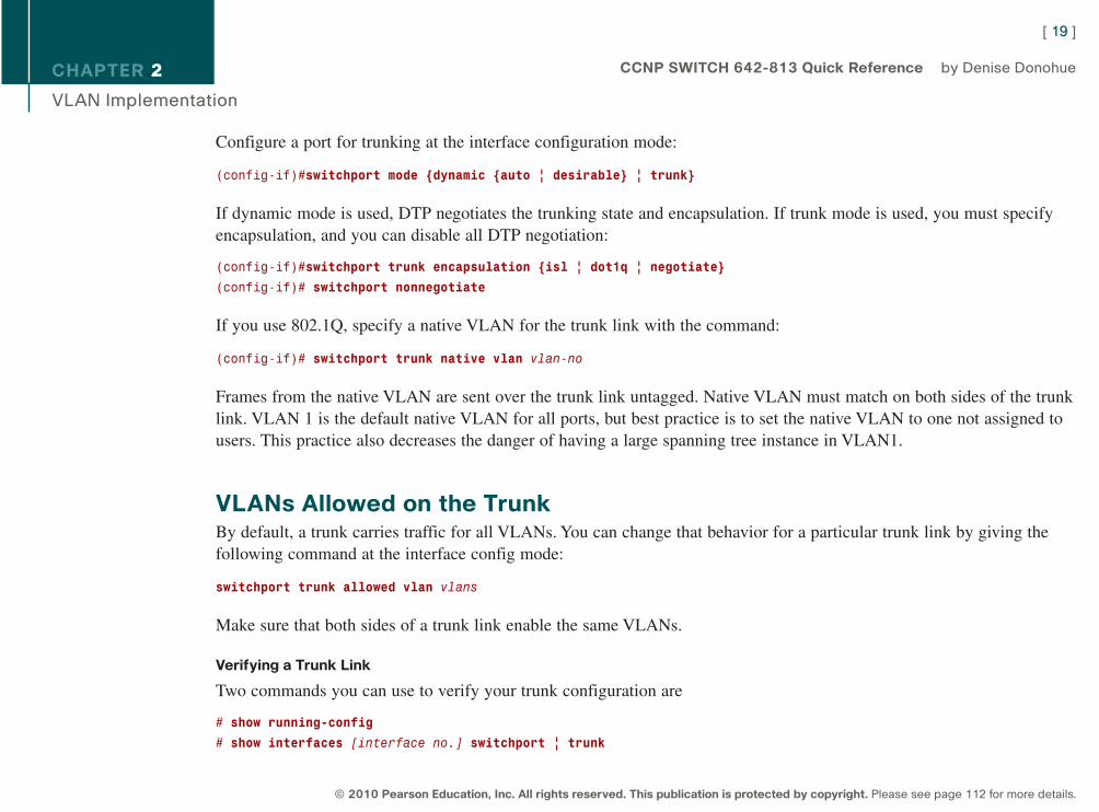
Configure a port for trunking at the interface configuration mode:
(config-if)#switchport mode {dynamic {auto | desirable} | trunk}
If dynamic mode is used, DTP negotiates the trunking state and encapsulation. If trunk mode is used, you must specifyencapsulation, and you can disable all DTP negotiation:
(config-if)#switchport trunk encapsulation {isl | dot1q | negotiate}
(config-if)# switchport nonnegotiate
If you use 802.1Q, specify a native VLAN for the trunk link with the command:
(config-if)# switchport trunk native vlan vlan-no
Frames from the native VLAN are sent over the trunk link untagged. Native VLAN must match on both sides of the trunklink. VLAN 1 is the default native VLAN for all ports, but best practice is to set the native VLAN to one not assigned tousers. This practice also decreases the danger of having a large spanning tree instance in VLAN1.
VLANs Allowed on the TrunkBy default, a trunk carries traffic for all VLANs. You can change that behavior for a particular trunk link by giving thefollowing command at the interface config mode:
switchport trunk allowed vlan vlans
Make sure that both sides of a trunk link enable the same VLANs.
Verifying a Trunk Link
Two commands you can use to verify your trunk configuration are
# show running-config
# show interfaces [interface no.] switchport | trunk
[ 19 ]
© 2010 Pearson Education, Inc. All rights reserved. This publication is protected by copyright. Please see page 112 for more details.
CCNP SWITCH 642-813 Quick Reference by Denise Donohue
9781587140112.qxd 11/23/09 11:34 AM Page 19
CHAPTER 2
VLAN Implementation
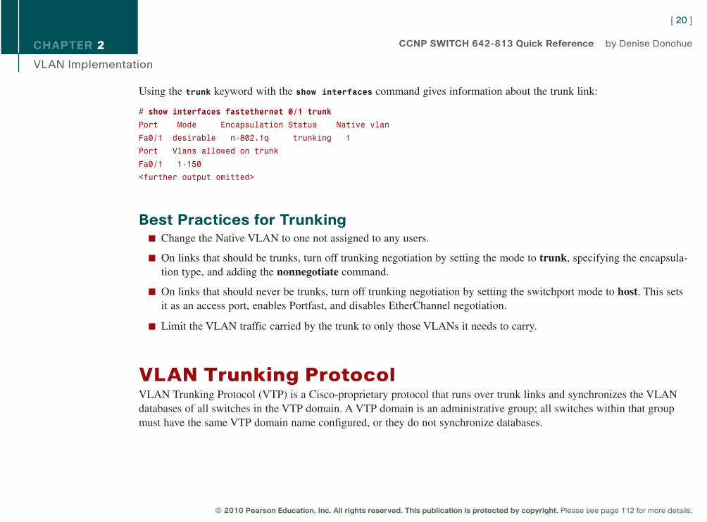
Using the trunk keyword with the show interfaces command gives information about the trunk link:
# show interfaces fastethernet 0/1 trunk
Port Mode Encapsulation Status Native vlan
Fa0/1 desirable n-802.1q trunking 1
Port Vlans allowed on trunk
Fa0/1 1-150
<further output omitted>
Best Practices for Trunkingn Change the Native VLAN to one not assigned to any users.
n On links that should be trunks, turn off trunking negotiation by setting the mode to trunk, specifying the encapsula-tion type, and adding the nonnegotiate command.
n On links that should never be trunks, turn off trunking negotiation by setting the switchport mode to host. This setsit as an access port, enables Portfast, and disables EtherChannel negotiation.
n Limit the VLAN traffic carried by the trunk to only those VLANs it needs to carry.
VLAN Trunking Protocol VLAN Trunking Protocol (VTP) is a Cisco-proprietary protocol that runs over trunk links and synchronizes the VLANdatabases of all switches in the VTP domain. A VTP domain is an administrative group; all switches within that groupmust have the same VTP domain name configured, or they do not synchronize databases.
[ 20 ]
© 2010 Pearson Education, Inc. All rights reserved. This publication is protected by copyright. Please see page 112 for more details.
CCNP SWITCH 642-813 Quick Reference by Denise Donohue
9781587140112.qxd 11/23/09 11:34 AM Page 20
CHAPTER 2
VLAN Implementation
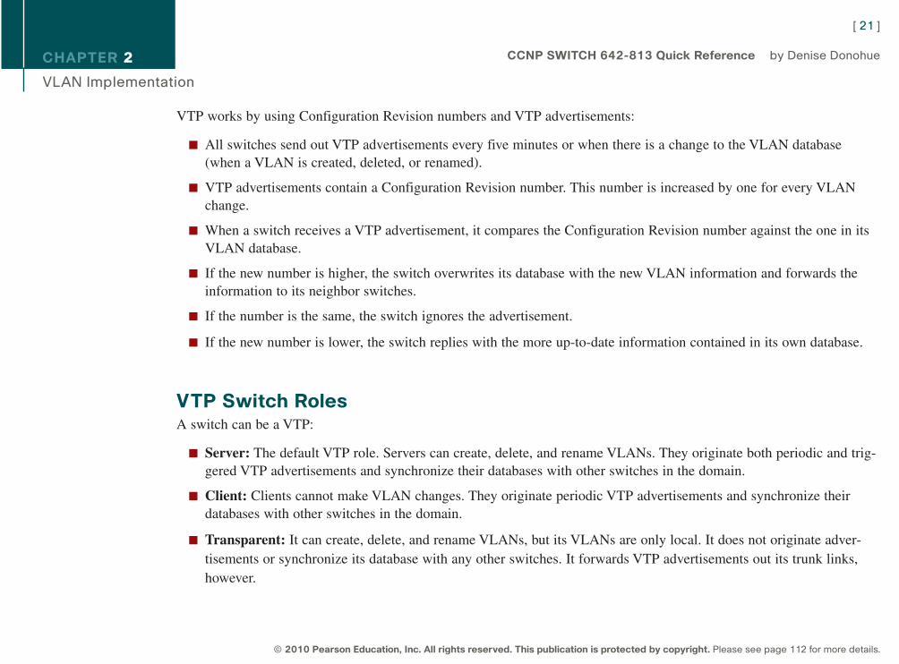
VTP works by using Configuration Revision numbers and VTP advertisements:
n All switches send out VTP advertisements every five minutes or when there is a change to the VLAN database(when a VLAN is created, deleted, or renamed).
n VTP advertisements contain a Configuration Revision number. This number is increased by one for every VLANchange.
n When a switch receives a VTP advertisement, it compares the Configuration Revision number against the one in itsVLAN database.
n If the new number is higher, the switch overwrites its database with the new VLAN information and forwards theinformation to its neighbor switches.
n If the number is the same, the switch ignores the advertisement.
n If the new number is lower, the switch replies with the more up-to-date information contained in its own database.
VTP Switch RolesA switch can be a VTP:
n Server: The default VTP role. Servers can create, delete, and rename VLANs. They originate both periodic and trig-gered VTP advertisements and synchronize their databases with other switches in the domain.
n Client: Clients cannot make VLAN changes. They originate periodic VTP advertisements and synchronize theirdatabases with other switches in the domain.
n Transparent: It can create, delete, and rename VLANs, but its VLANs are only local. It does not originate adver-tisements or synchronize its database with any other switches. It forwards VTP advertisements out its trunk links,however.
[ 21 ]
© 2010 Pearson Education, Inc. All rights reserved. This publication is protected by copyright. Please see page 112 for more details.
CCNP SWITCH 642-813 Quick Reference by Denise Donohue
9781587140112.qxd 11/23/09 11:34 AM Page 21
CHAPTER 2
VLAN Implementation
The two versions of VTP are Version 1 and Version 2. To use Version 2, all switches in the domain must be capable ofusing it. Configure one server for Version 2, and the information is propagated through VTP. Version 2 has the followingadded features:
n It supports Token Ring VLANs.
n Transparent switches pass along messages from both versions of VTP.
n Consistency checks are performed only when changes are configured through the CLI or SNMP.
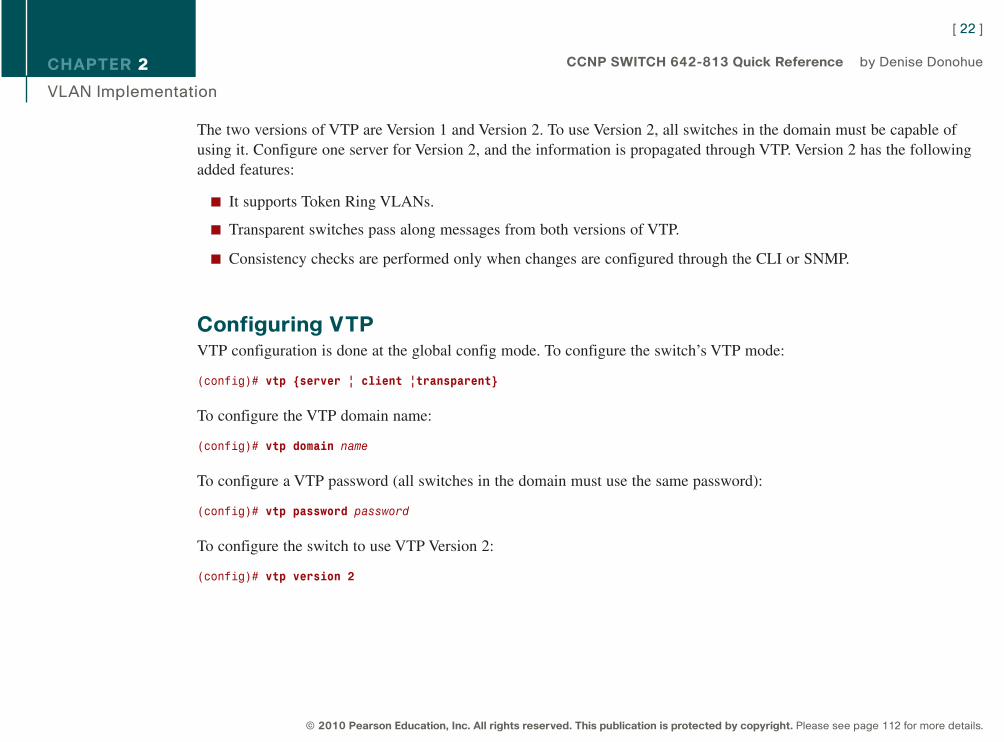
Configuring VTPVTP configuration is done at the global config mode. To configure the switch’s VTP mode:
(config)# vtp {server | client |transparent}
To configure the VTP domain name:
(config)# vtp domain name
To configure a VTP password (all switches in the domain must use the same password):
(config)# vtp password password
To configure the switch to use VTP Version 2:
(config)# vtp version 2
[ 22 ]
© 2010 Pearson Education, Inc. All rights reserved. This publication is protected by copyright. Please see page 112 for more details.
CCNP SWITCH 642-813 Quick Reference by Denise Donohue
9781587140112.qxd 11/23/09 11:34 AM Page 22
CHAPTER 2
VLAN Implementation
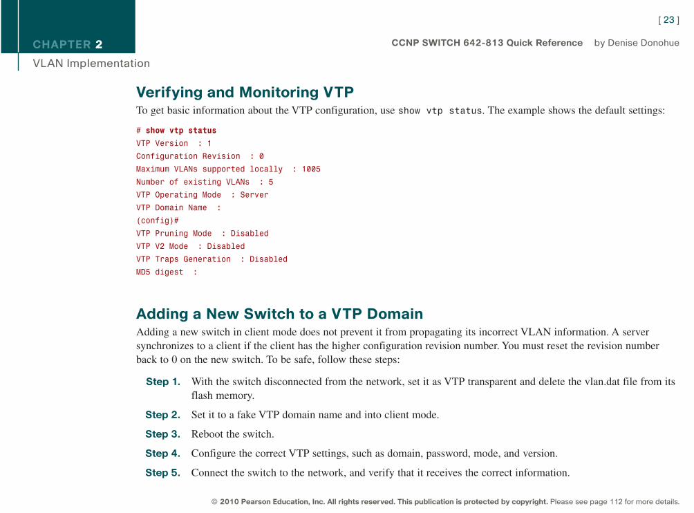
Verifying and Monitoring VTPTo get basic information about the VTP configuration, use show vtp status. The example shows the default settings:
# show vtp status
VTP Version : 1
Configuration Revision : 0
Maximum VLANs supported locally : 1005
Number of existing VLANs : 5
VTP Operating Mode : Server
VTP Domain Name :
(config)#
VTP Pruning Mode : Disabled
VTP V2 Mode : Disabled
VTP Traps Generation : Disabled
MD5 digest :
Adding a New Switch to a VTP DomainAdding a new switch in client mode does not prevent it from propagating its incorrect VLAN information. A serversynchronizes to a client if the client has the higher configuration revision number. You must reset the revision numberback to 0 on the new switch. To be safe, follow these steps:
Step 1. With the switch disconnected from the network, set it as VTP transparent and delete the vlan.dat file from itsflash memory.
Step 2. Set it to a fake VTP domain name and into client mode.
Step 3. Reboot the switch.
Step 4. Configure the correct VTP settings, such as domain, password, mode, and version.
Step 5. Connect the switch to the network, and verify that it receives the correct information.
[ 23 ]
© 2010 Pearson Education, Inc. All rights reserved. This publication is protected by copyright. Please see page 112 for more details.
CCNP SWITCH 642-813 Quick Reference by Denise Donohue
9781587140112.qxd 11/23/09 11:34 AM Page 23
CHAPTER 2
VLAN Implementation
EtherChannelsAn EtherChannel is a way of combining several physical links between switches into one logical connection. Normally,Spanning Tree blocks redundant links; EtherChannels get around that and enable load balancing across those links.Traffic is balanced between the channel links on the basis of such things as source or destination MAC address or IPaddress. The EtherChannel load-balancing method is configured at global configuration mode.
(config)# port-channel load-balance type
A logical interface—called the Port Channel interface—is created. Configuration can be applied to both the logical andphysical interfaces.
Some guidelines for EtherChannels follows:
n Interfaces in the channel do not have to be physically next to each other or on the same module.
n All ports must be the same speed and duplex.
n All ports in the bundle should be enabled.
n None of the bundle ports can be a SPAN port.
n Assign an IP address to the logical Port Channel interface, not the physical ones, if using a Layer 3 EtherChannel.
n Put all bundle ports in the same VLAN, or make them all trunks. If they are trunks, they must all carry the sameVLANs and use the same trunking mode.
n The configuration you apply to the Port Channel interface affects the entire EtherChannel. The configuration youapply to a physical interface affects only that interface.
[ 24 ]
© 2010 Pearson Education, Inc. All rights reserved. This publication is protected by copyright. Please see page 112 for more details.
CCNP SWITCH 642-813 Quick Reference by Denise Donohue
9781587140112.qxd 11/23/09 11:34 AM Page 24
CHAPTER 2
VLAN Implementation
Configuring an EtherChannelBasically, you should configure the logical interface and then put the physical interfaces into the channel group:
(config)# interface port-channel number
![any additional configuration, such as trunking for a Layer 2 EtherChannel]
For a Layer 3 EtherChannel, add the following:
(config-if)# no switchport
(config-if)# ip address address mask
Then, at each port that is part of the EtherChannel, use the following:
(config)# interface { number | range interface – interface}
(config-if)# channel-group number mode {auto | desirable | on}
Putting the IP address on the Port Channel interface creates a Layer 3 EtherChannel. Simply putting interfaces into achannel group creates a Layer 2 EtherChannel, and the logical interface is automatically created.
The Cisco proprietary Port Aggregation Protocol (PAgP) dynamically negotiates the formation of a channel. There arethree PAgP modes:
n On: The port channels without using PAgP negotiation. The port on the other side must also be set to On.
n Auto: Responds to PAgP messages but does not initiate them. Port channels if the port on the other end is set toDesirable. This is the default mode.
n Desirable: Port actively negotiates channeling status with the interface on the other end of the link. Port channels ifthe other side is Auto or Desirable.
[ 25 ]
© 2010 Pearson Education, Inc. All rights reserved. This publication is protected by copyright. Please see page 112 for more details.
CCNP SWITCH 642-813 Quick Reference by Denise Donohue
9781587140112.qxd 11/23/09 11:34 AM Page 25
CHAPTER 2
VLAN Implementation
Link Aggregation Control Protocol (LACP) is an IEEE standard protocol, IEEE 802.3ad, which does the same thing.LACP modes follow:
n On: The port channels without using LACP negotiation. The port on the other side must also be set to On.
n Active: Port actively negotiates channeling with the port on the other end of the link. A channel forms if the otherside is Passive or Active.
n Passive: Responds to LACP messages but does not initiate them. A channel forms only if the other end is set toActive.
If you want to use LACP, specify it under the interface and put the interface in either active or passive mode:
(config-if)# channel-protocol lacp
(config-if) channel-group number mode {active | passive}
Verifying an EtherChannelSome typical commands for verifying include the following:
# show running-config interface number
# show interfaces number etherchannel
# show etherchannel number port-channel
# show etherchannel summary
# show etherchannel load-balance
[ 26 ]
© 2010 Pearson Education, Inc. All rights reserved. This publication is protected by copyright. Please see page 112 for more details.
CCNP SWITCH 642-813 Quick Reference by Denise Donohue
9781587140112.qxd 11/23/09 11:34 AM Page 26
CHAPTER 2
VLAN Implementation
Troubleshooting VLAN IssuesConfiguration problems can arise when user traffic must traverse several switches. The following sections list somecommon configuration errors. But before you begin troubleshooting, create a plan. Check the implementation plan for anychanges recently made, and determine likely problem areas.
Troubleshooting User ConnectivityUser connectivity can be affected by several things:
n Physical connectivity: Make sure the cable, network adapter, and switch port are good. Check the port’s link LED.
n Switch configuration: If you see FCS errors or late collisions, suspect a duplex mismatch. Check configured speedon both sides of the link. Make sure the port is enabled and set as an access port.
n VLAN configuration: Make sure the hosts are in the correct VLAN.
n Allowed VLANs: Make sure that the user VLAN is allowed on all appropriate trunk links.
Troubleshooting TrunkingWhen troubleshooting trunking, make sure that physical layer connectivity is present before moving on to search forconfiguration problems such as
n Are both sides of the link in the correct trunking mode?
n Is the same trunk encapsulation on both sides?
n If 802.1Q, is the same native VLAN on both sides? Look for CDP messages warning of this error.
n Are the same VLANs permitted on both sides?
n Is a link trunking that should not be?
[ 27 ]
© 2010 Pearson Education, Inc. All rights reserved. This publication is protected by copyright. Please see page 112 for more details.
CCNP SWITCH 642-813 Quick Reference by Denise Donohue
9781587140112.qxd 11/23/09 11:34 AM Page 27
CHAPTER 2
VLAN Implementation
Troubleshooting VTPThe following are some common things to check when troubleshooting problems with VTP:
n Make sure you are trunking between the switches. VTP is sent only over trunk links.
n Make sure the domain name matches on both switches. (The name is case sensitive.)
n If the switch is not updating its database, make sure it is not in transparent mode.
n If using passwords, make sure they all match. To remove a password, use no vtp password.
n If VLANs are missing, check the Revision number for a possible database overwrite. Also check the number ofVLANs in the domain. There might be too many VLANs for VTP to update properly.
[ 28 ]
© 2010 Pearson Education, Inc. All rights reserved. This publication is protected by copyright. Please see page 112 for more details.
CCNP SWITCH 642-813 Quick Reference by Denise Donohue
9781587140112.qxd 11/23/09 11:34 AM Page 28
CHAPTER 3
Spanning Tree
Chapter 3Spanning Tree
Ethernet network design balances two separate imperatives. First, Ethernet has no capacity for detecting circular paths. Ifsuch paths exist, traffic loops around and accumulates until new traffic is shut out. (This is called a broadcast storm.)Second, having secondary paths is good preparation for inevitable link failure.
Spanning Tree is a protocol that prevents loop formation by detecting redundant links and disabling them until needed.Designers can therefore build redundant links, and the protocol enables one to pass traffic and keep the other in reserve.When the active link fails, the secondary link is enabled quickly.
Understanding the Spanning Tree ProtocolSwitches either forward or filter Layer 2 frames. The way they make the forwarding/filtering decision can lead to loops ina network with redundant links. Spanning Tree is a protocol that detects potential loops and breaks them.
A Layer 2 switch is functionally the same thing as a transparent bridge. Transparent bridges:
n Learn MAC (Media Access Control) addresses by looking at the source address of incoming frames. They build atable mapping MAC address to port number.
n Forward broadcasts and multicasts out all ports except the one in which they came. (This is called flooding.)
n Forward unknown unicasts out all ports except the one in which they came. An unknown unicast is a message boundfor a unicast MAC address that is not in the switch’s table of addresses and ports.
n Do not make any changes to the frames as they forward them.
[ 29 ]
© 2010 Pearson Education, Inc. All rights reserved. This publication is protected by copyright. Please see page 112 for more details.
CCNP SWITCH 642-813 Quick Reference by Denise Donohue
9781587140112.qxd 11/23/09 11:34 AM Page 29
CHAPTER 3
Spanning Tree
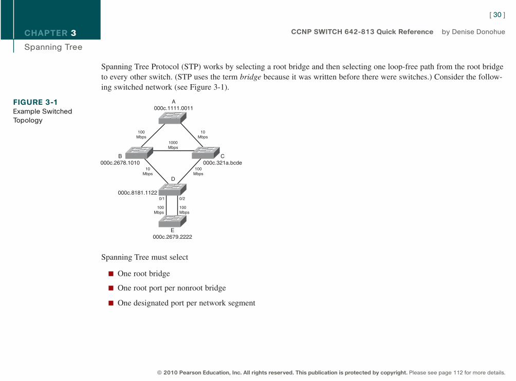
Spanning Tree Protocol (STP) works by selecting a root bridge and then selecting one loop-free path from the root bridgeto every other switch. (STP uses the term bridge because it was written before there were switches.) Consider the follow-ing switched network (see Figure 3-1).
Spanning Tree must select
n One root bridge
n One root port per nonroot bridge
n One designated port per network segment
[ 30 ]
© 2010 Pearson Education, Inc. All rights reserved. This publication is protected by copyright. Please see page 112 for more details.
CCNP SWITCH 642-813 Quick Reference by Denise Donohue
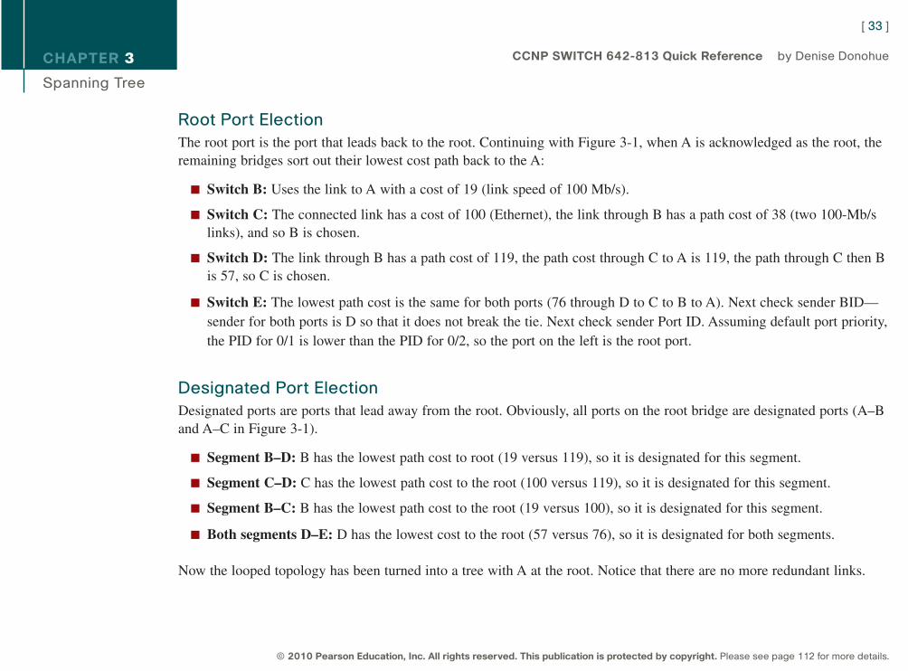
FIGURE 3-1Example Switched
Topology
A000c.1111.0011
B000c.2678.1010
C000c.321a.bcde
000c.8181.1122
E000c.2679.2222
100Mbps
1000Mbps
10Mbps
10Mbps
100Mbps
100Mbps
100Mbps
0/1 0/2
D
9781587140112.qxd 11/23/09 11:34 AM Page 30
CHAPTER 3
Spanning Tree
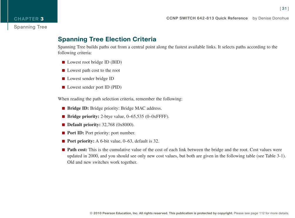
Spanning Tree Election CriteriaSpanning Tree builds paths out from a central point along the fastest available links. It selects paths according to thefollowing criteria:
n Lowest root bridge ID (BID)
n Lowest path cost to the root
n Lowest sender bridge ID
n Lowest sender port ID (PID)
When reading the path selection criteria, remember the following:
n Bridge ID: Bridge priority: Bridge MAC address.
n Bridge priority: 2-btye value, 0–65,535 (0–0xFFFF).
n Default priority: 32,768 (0x8000).
n Port ID: Port priority: port number.
n Port priority: A 6-bit value, 0–63, default is 32.
n Path cost: This is the cumulative value of the cost of each link between the bridge and the root. Cost values wereupdated in 2000, and you should see only new cost values, but both are given in the following table (see Table 3-1).Old and new switches work together.
[ 31 ]
© 2010 Pearson Education, Inc. All rights reserved. This publication is protected by copyright. Please see page 112 for more details.
CCNP SWITCH 642-813 Quick Reference by Denise Donohue
9781587140112.qxd 11/23/09 11:34 AM Page 31
CHAPTER 3
Spanning Tree
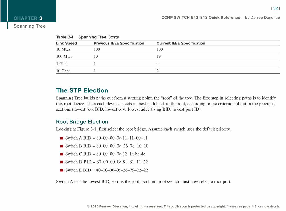
Table 3-1 Spanning Tree Costs
Link Speed Previous IEEE Specification Current IEEE Specification
10 Mb/s 100 100
100 Mb/s 10 19
1 Gbps 1 4
10 Gbps 1 2
The STP ElectionSpanning Tree builds paths out from a starting point, the “root” of the tree. The first step in selecting paths is to identifythis root device. Then each device selects its best path back to the root, according to the criteria laid out in the previoussections (lowest root BID, lowest cost, lowest advertising BID, lowest port ID).
Root Bridge Election
Looking at Figure 3-1, first select the root bridge. Assume each switch uses the default priority.
n Switch A BID = 80–00–00–0c-11–11–00–11
n Switch B BID = 80–00–00–0c–26–78–10–10
n Switch C BID = 80–00–00–0c-32–1a-bc-de
n Switch D BID = 80–00–00–0c-81–81–11–22
n Switch E BID = 80–00–00–0c–26–79–22–22
Switch A has the lowest BID, so it is the root. Each nonroot switch must now select a root port.
[ 32 ]
© 2010 Pearson Education, Inc. All rights reserved. This publication is protected by copyright. Please see page 112 for more details.
CCNP SWITCH 642-813 Quick Reference by Denise Donohue
9781587140112.qxd 11/23/09 11:34 AM Page 32
CHAPTER 3
Spanning Tree
Root Port Election
The root port is the port that leads back to the root. Continuing with Figure 3-1, when A is acknowledged as the root, theremaining bridges sort out their lowest cost path back to the A:
n Switch B: Uses the link to A with a cost of 19 (link speed of 100 Mb/s).
n Switch C: The connected link has a cost of 100 (Ethernet), the link through B has a path cost of 38 (two 100-Mb/slinks), and so B is chosen.
n Switch D: The link through B has a path cost of 119, the path cost through C to A is 119, the path through C then Bis 57, so C is chosen.
n Switch E: The lowest path cost is the same for both ports (76 through D to C to B to A). Next check sender BID—sender for both ports is D so that it does not break the tie. Next check sender Port ID. Assuming default port priority,the PID for 0/1 is lower than the PID for 0/2, so the port on the left is the root port.
Designated Port Election
Designated ports are ports that lead away from the root. Obviously, all ports on the root bridge are designated ports (A–Band A–C in Figure 3-1).
n Segment B–D: B has the lowest path cost to root (19 versus 119), so it is designated for this segment.
n Segment C–D: C has the lowest path cost to the root (100 versus 119), so it is designated for this segment.
n Segment B–C: B has the lowest path cost to the root (19 versus 100), so it is designated for this segment.
n Both segments D–E: D has the lowest cost to the root (57 versus 76), so it is designated for both segments.
Now the looped topology has been turned into a tree with A at the root. Notice that there are no more redundant links.
[ 33 ]
© 2010 Pearson Education, Inc. All rights reserved. This publication is protected by copyright. Please see page 112 for more details.
CCNP SWITCH 642-813 Quick Reference by Denise Donohue
9781587140112.qxd 11/23/09 11:34 AM Page 33
CHAPTER 3
Spanning Tree
Bridge Protocol Data Units Switches exchange Bridge Protocol Data Units (BPDU). The two types of BPDUs are Configuration and TopologyChange Notification(TCN). Configuration BPDUs are sent every two seconds from the root toward the downstreamswitches. They:
n Are used during an election
n Maintain connectivity between switches
n Send timer information from the root
[ 34 ]
© 2010 Pearson Education, Inc. All rights reserved. This publication is protected by copyright. Please see page 112 for more details.
CCNP SWITCH 642-813 Quick Reference by Denise Donohue
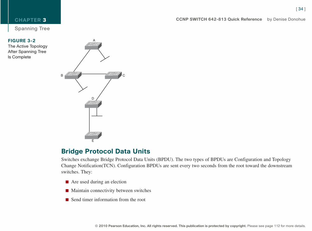
FIGURE 3-2The Active Topology
After Spanning Tree
Is Complete
A
B C
D
E
9781587140112.qxd 11/23/09 11:34 AM Page 34
CHAPTER 3
Spanning Tree
TCN BPDUs are sent by a downstream switch toward the root when:
n There is a link failure.
n A port starts forwarding, and there is already a designated port.
n The switch receives a TCN from a neighbor.
When a switch receives a TCN BPDU, it acknowledges that with a configuration BPDU that has the TCNAcknowledgment bit set.
When the root bridge receives a TCN, it starts sending configuration BPDUs with the TCN bit set for a period of timeequal to max age plus forward delay. Switches that receive this change their MAC table aging time to the Forward Delaytime, causing MAC addresses to age faster. The topology change also causes an election of the root bridge, root ports, anddesignated ports.
Some of the fields in the BPDU include:
n Root bridge ID: The BID of the current root
n Sender’s root path cost: The cost to the root
n Sender’s bridge ID: Sender’s priority concatenated to MAC
n Sender’s port ID: The port number, transmitted as final tie-breaker
n Hello time: Two seconds by default
n Forward Delay: Fifteen seconds by default
n Max Age: Twenty seconds by default
[ 35 ]
© 2010 Pearson Education, Inc. All rights reserved. This publication is protected by copyright. Please see page 112 for more details.
CCNP SWITCH 642-813 Quick Reference by Denise Donohue
9781587140112.qxd 11/23/09 11:34 AM Page 35
CHAPTER 3
Spanning Tree
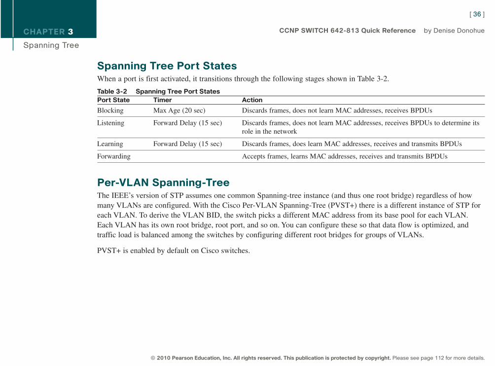
Spanning Tree Port StatesWhen a port is first activated, it transitions through the following stages shown in Table 3-2.
Table 3-2 Spanning Tree Port StatesPort State Timer Action
Blocking Max Age (20 sec) Discards frames, does not learn MAC addresses, receives BPDUs
Listening Forward Delay (15 sec) Discards frames, does not learn MAC addresses, receives BPDUs to determine itsrole in the network
Learning Forward Delay (15 sec) Discards frames, does learn MAC addresses, receives and transmits BPDUs
Forwarding Accepts frames, learns MAC addresses, receives and transmits BPDUs
Per-VLAN Spanning-TreeThe IEEE’s version of STP assumes one common Spanning-tree instance (and thus one root bridge) regardless of howmany VLANs are configured. With the Cisco Per-VLAN Spanning-Tree (PVST+) there is a different instance of STP foreach VLAN. To derive the VLAN BID, the switch picks a different MAC address from its base pool for each VLAN.Each VLAN has its own root bridge, root port, and so on. You can configure these so that data flow is optimized, andtraffic load is balanced among the switches by configuring different root bridges for groups of VLANs.
PVST+ is enabled by default on Cisco switches.
[ 36 ]
© 2010 Pearson Education, Inc. All rights reserved. This publication is protected by copyright. Please see page 112 for more details.
CCNP SWITCH 642-813 Quick Reference by Denise Donohue
9781587140112.qxd 11/23/09 11:34 AM Page 36
CHAPTER 3
Spanning Tree
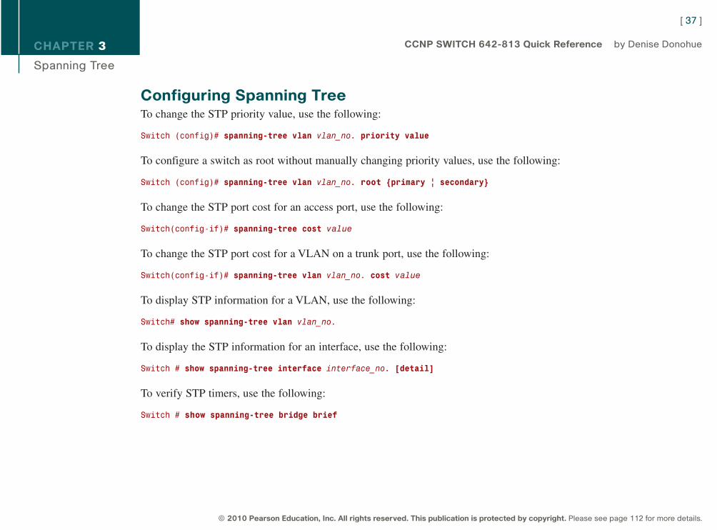
Configuring Spanning TreeTo change the STP priority value, use the following:
Switch (config)# spanning-tree vlan vlan_no. priority value
To configure a switch as root without manually changing priority values, use the following:
Switch (config)# spanning-tree vlan vlan_no. root {primary | secondary}
To change the STP port cost for an access port, use the following:
Switch(config-if)# spanning-tree cost value
To change the STP port cost for a VLAN on a trunk port, use the following:
Switch(config-if)# spanning-tree vlan vlan_no. cost value
To display STP information for a VLAN, use the following:
Switch# show spanning-tree vlan vlan_no.
To display the STP information for an interface, use the following:
Switch # show spanning-tree interface interface_no. [detail]
To verify STP timers, use the following:
Switch # show spanning-tree bridge brief
[ 37 ]
© 2010 Pearson Education, Inc. All rights reserved. This publication is protected by copyright. Please see page 112 for more details.
CCNP SWITCH 642-813 Quick Reference by Denise Donohue
9781587140112.qxd 11/23/09 11:34 AM Page 37
CHAPTER 3
Spanning Tree
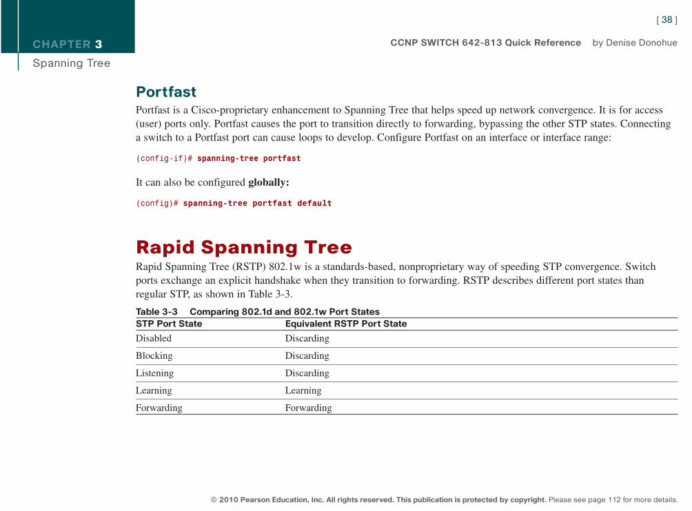
PortfastPortfast is a Cisco-proprietary enhancement to Spanning Tree that helps speed up network convergence. It is for access(user) ports only. Portfast causes the port to transition directly to forwarding, bypassing the other STP states. Connectinga switch to a Portfast port can cause loops to develop. Configure Portfast on an interface or interface range:
(config-if)# spanning-tree portfast
It can also be configured globally:
(config)# spanning-tree portfast default
Rapid Spanning TreeRapid Spanning Tree (RSTP) 802.1w is a standards-based, nonproprietary way of speeding STP convergence. Switchports exchange an explicit handshake when they transition to forwarding. RSTP describes different port states thanregular STP, as shown in Table 3-3.
Table 3-3 Comparing 802.1d and 802.1w Port StatesSTP Port State Equivalent RSTP Port State
Disabled Discarding
Blocking Discarding
Listening Discarding
Learning Learning
Forwarding Forwarding
[ 38 ]
© 2010 Pearson Education, Inc. All rights reserved. This publication is protected by copyright. Please see page 112 for more details.
CCNP SWITCH 642-813 Quick Reference by Denise Donohue
9781587140112.qxd 11/23/09 11:34 AM Page 38
CHAPTER 3
Spanning Tree
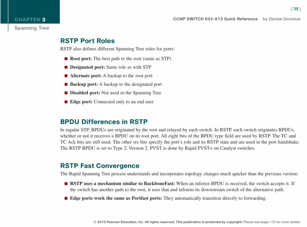
RSTP Port RolesRSTP also defines different Spanning Tree roles for ports:
n Root port: The best path to the root (same as STP)
n Designated port: Same role as with STP
n Alternate port: A backup to the root port
n Backup port: A backup to the designated port
n Disabled port: Not used in the Spanning Tree
n Edge port: Connected only to an end user
BPDU Differences in RSTPIn regular STP, BPDUs are originated by the root and relayed by each switch. In RSTP, each switch originates BPDUs,whether or not it receives a BPDU on its root port. All eight bits of the BPDU type field are used by RSTP. The TC andTC Ack bits are still used. The other six bits specify the port’s role and its RSTP state and are used in the port handshake.The RSTP BPDU is set to Type 2, Version 2. PVST is done by Rapid PVST+ on Catalyst switches.
RSTP Fast ConvergenceThe Rapid Spanning Tree process understands and incorporates topology changes much quicker than the previous version:
n RSTP uses a mechanism similar to BackboneFast: When an inferior BPDU is received, the switch accepts it. Ifthe switch has another path to the root, it uses that and informs its downstream switch of the alternative path.
n Edge ports work the same as Portfast ports: They automatically transition directly to forwarding.
[ 39 ]
© 2010 Pearson Education, Inc. All rights reserved. This publication is protected by copyright. Please see page 112 for more details.
CCNP SWITCH 642-813 Quick Reference by Denise Donohue
9781587140112.qxd 11/23/09 11:34 AM Page 39
CHAPTER 3
Spanning Tree
n Link type: If you connect two switches through a point-to-point link and the local port becomes a designated port, itexchanges a handshake with the other port to quickly transition to forwarding. Full-duplex links are assumed to bepoint-to-point; half-duplex links are assumed to be shared.
n Backup and alternate ports: Ports that can transition to forwarding when no BPDUs are received from a neighborswitch (similar to UplinkFast).
If an RSTP switch detects a topology change, it sets a TC timer to twice the hello time and sets the TC bit on all BPDUssent out its designated and root ports until the timer expires. It also clears the MAC addresses learned on these ports.Only changes to the status of non-Edge ports cause a TC notification.
If an RSTP switch receives a TC BPDU, it clears the MAC addresses on that port and sets the TC bit on all BPDUs sentout its designated and root ports until the TC timer expires. Enable and verify Rapid STP with the commands:
Switch(config)# spanning-tree mode rapid-pvst
Switch# show spanning-tree
A version of PVST+ is used with Rapid Spanning Tree, called Per-VLAN Rapid Spanning Tree (PVRST+). You shouldstill configure root and secondary root bridges for each VLAN when using RSTP.
Multiple Spanning TreeWith Multiple Spanning Tree (MST), you can group VLANs and run one instance of Spanning Tree for a group ofVLANs. This cuts down on the number of root bridges, root ports, designated ports, and BPDUs in your network.Switches in the same MST Region share the same configuration and VLAN mappings. Configure and verify MST withthese commands:
(config)# spanning-tree mode mst
(config)# spanning-tree mst configuration
(config-mst)# name region_name
[ 40 ]
© 2010 Pearson Education, Inc. All rights reserved. This publication is protected by copyright. Please see page 112 for more details.
CCNP SWITCH 642-813 Quick Reference by Denise Donohue
9781587140112.qxd 11/23/09 11:35 AM Page 40
CHAPTER 3
Spanning Tree
(config-mst)# revision number
(config-mst)# instance number vlan vlan_range
(config-mst)# end
# show spanning-tree mst
To be compatible with 802.1Q trunking, which has one common Spanning Tree (CST) for all VLANs, MST runs oneinstance of an Internal Spanning Tree (IST). The IST appears as one bridge to a CST area and is MST instance number 0.The original MST Spanning Trees (called M-Trees) are active only in the region; they combine at the edge of the CSTarea to form one.
Spanning Tree Stability MechanismsSpanning Tree has several additional tools for tuning STP to protect the network and keep it operating properly. Theyinclude:
n PortFast (discussed previously)
n UplinkFast
n BackboneFast
n BPDU Guard
n BPDU Filtering
n Root Guard
n UDLD
n Loop Guard
[ 41 ]
© 2010 Pearson Education, Inc. All rights reserved. This publication is protected by copyright. Please see page 112 for more details.
CCNP SWITCH 642-813 Quick Reference by Denise Donohue
9781587140112.qxd 11/23/09 11:35 AM Page 41
CHAPTER 3
Spanning Tree
UplinkFastUplinkFast is for speeding convergence when a direct link to an upstream switch fails. The switch identifies backup portsfor the root port. (These are called an uplink group.) If the root port fails, one of the ports in the uplink group isunblocked and transitions immediately to forwarding; it bypasses the listening and learning stages. It should be used inwiring closet switches with at least one blocked port.
The command to enable uplinkfast is shown next. Please note that uplinkfast is enabled globally, so the command affectsall ports and all VLANs.
(config)# spanning-tree uplinkfast
BackboneFastBackboneFast is used for speeding convergence when a link fails that is not directly connected to the switch. It helps theswitch detect indirect failures. If a switch running BackboneFast receives an inferior BPDU from its designated bridge, itknows a link on the path to the root has failed. (An inferior BPDU is one that lists the same switch for the root bridge anddesignated bridge.)
The switch then tries to find an alternate path to the root by sending a Root Link Query (RLQ) frame out all alternateports. The root then responds with an RLQ response, and the port receiving this response can transition to forwarding.Alternate ports are determined in this way:
n If the inferior BPDU was received on a blocked port, the root port and any other blocked ports are considered alternates.
n If the inferior BPDU was received on the root port, all blocked ports are considered alternates.
n If the inferior BPDU was received on the root port and there are no blocked ports, the switch assumes it has lostconnectivity with the root and advertises itself as root.
[ 42 ]
© 2010 Pearson Education, Inc. All rights reserved. This publication is protected by copyright. Please see page 112 for more details.
CCNP SWITCH 642-813 Quick Reference by Denise Donohue
9781587140112.qxd 11/23/09 11:35 AM Page 42
CHAPTER 3
Spanning Tree
Configure this command on all switches in the network:
(config)# spanning-tree backbonefast
BPDU GuardBPDU Guard prevents loops if another switch is attached to a Portfast port. When BPDU Guard is enabled on an inter-face, it is put into an error-disabled state (basically, shut down) if a BPDU is received on the interface. It can be enabledat either global config mode—in which case it affects all Portfast interfaces—or at interface mode. Portfast does not needto be enabled for it to be configured at a specific interface. The following configuration example shows BPDU guardbeing enabled and verified.
(config)# spanning-tree portfast bpduguard default
(config-if)# spanning-tree bpduguard enable
# show spanning-tree summary totals
BPDU FilteringBPDU filtering is another way of preventing loops in the network. It also can be enabled either globally or at the interfaceand functions differently at each. In global config, if a Portfast interface receives any BPDUs, it is taken out of Portfaststatus. At interface config mode, it prevents the port from sending or receiving BPDUs. The commands are:
(config)# spanning-tree portfast bpdufilter default
(config-if)# spanning-tree bpdufilter enable
[ 43 ]
© 2010 Pearson Education, Inc. All rights reserved. This publication is protected by copyright. Please see page 112 for more details.
CCNP SWITCH 642-813 Quick Reference by Denise Donohue
9781587140112.qxd 11/23/09 11:35 AM Page 43
CHAPTER 3
Spanning Tree
Root GuardRoot Guard is meant to prevent the wrong switch from becoming the Spanning Tree root. It is enabled on ports other thanthe root port and on switches other than the root. If a Root Guard port receives a BPDU that might cause it to become aroot port, the port is put into “root-inconsistent” state and does not pass traffic through it. If the port stops receiving theseBPDUs, it automatically reenables itself. To enable and verify Root Guard use the following commands:
(config-if)# spanning-tree guard root
# show spanning-tree inconsistentports
Unidirectional Link DetectionA switch notices when a physical connection is broken by the absence of Layer 1 electrical keepalives. (Ethernet callsthis a link beat.) However, sometimes a cable is intact enough to maintain keepalives but not to pass data in both direc-tions. This is a Unidirectional Link. Operating at Layer 2, Unidirectional Link Detection (UDLD) detects a unidirectionallink by sending periodic hellos out to the interface. It also uses probes, which must be acknowledged by the device on theother end of the link.
UDLD has two modes: normal and aggressive. In normal mode, the link status is changed to Undetermined State if thehellos are not returned. In aggressive mode, the port is error-disabled if a unidirectional link is found. Aggressive mode isthe recommended way to configure UDLD.
To enable UDLD on all fiber-optic interfaces, use the following command:
(config)# udld [enable | aggressive]
Although this command is given at global config mode, it applies only to fiber ports.
To enable UDLD on nonfiber ports, give the same command at interface config mode.
[ 44 ]
© 2010 Pearson Education, Inc. All rights reserved. This publication is protected by copyright. Please see page 112 for more details.
CCNP SWITCH 642-813 Quick Reference by Denise Donohue
9781587140112.qxd 11/23/09 11:35 AM Page 44
CHAPTER 3
Spanning Tree
To control UDLD on a specific fiber port, use the following command:
(config-if)# udld port {aggressive | disable}
To reenable all interfaces shut by UDLD, use the following:
# udld reset
To verify UDLD status, use the following:
# show udld interface
Loop GuardLoop Guard prevents loops that might develop if a port that should be blocking inadvertently transitions to the forwardingstate. This can happen if the port stops receiving BPDUs (perhaps because of a unidirectional link or a software/configu-ration problem in its neighbor switch). When one of the ports in a physically redundant topology stops receiving BPDUs,the STP conceives the topology as loop-free. Eventually, the blocking port becomes designated and moves to forwardingstate, thus creating a loop. With Loop Guard enabled, an additional check is made.
If no BPDUs are received on a blocked port for a specific length of time, Loop Guard puts that port into “loop inconsis-tent” blocking state, rather than transitioning to forwarding state. Loop Guard should be enabled on all switch ports thathave a chance of becoming root or designated ports. It is most effective when enabled in the entire switched network inconjunction with UDLD.
To enable Loop Guard for all point-to-point links on the switch, use the following command:
(config)# spanning-tree loopguard default
[ 45 ]
© 2010 Pearson Education, Inc. All rights reserved. This publication is protected by copyright. Please see page 112 for more details.
CCNP SWITCH 642-813 Quick Reference by Denise Donohue
9781587140112.qxd 11/23/09 11:35 AM Page 45
CHAPTER 3
Spanning Tree
To enable Loop Guard on a specific interface, use the following:
(config-if)# spanning-tree guard loop
Loop Guard automatically reenables the port if it starts receiving BPDUs again.
Troubleshooting STPSome common things to look for when troubleshooting Spanning Tree Protocol include:
n Duplex mismatch: When one side of a link is half-duplex and the other is full-duplex. This causes late collisionsand FCS errors.
n Unidirectional link failure: The link is up but data flows only in one direction. It can cause loops.
n Frame corruption: Physical errors on the line cause BPDUs to be lost, and the port incorrectly begins forwarding.This is caused by duplex mismatch, bad cable, or cable too long.
n Resource errors: STP is implemented in software, so a switch with an overloaded CPU or memory might neglectsome STP duties.
n Port Fast configuration errors: Connecting a switch to two ports that have Port Fast enabled. This can cause aloop.
n STP tuning errors: Max age or forward delay set too short can cause a loop. A network diameter that is set too lowcauses BPDUs to be discarded and affects STP convergence.
[ 46 ]
© 2010 Pearson Education, Inc. All rights reserved. This publication is protected by copyright. Please see page 112 for more details.
CCNP SWITCH 642-813 Quick Reference by Denise Donohue
9781587140112.qxd 11/23/09 11:35 AM Page 46
CHAPTER 3
Spanning Tree
Identifying a Bridging LoopSuspect a loop if you see the following:
n You capture traffic on a link and see the same frames multiple times.
n All users in a bridging domain have connectivity problems at the same time.
n There is abnormally high port utilization.
To remedy a loop quickly, shut redundant ports and then enable them one at a time. Some switches enable debugging ofSTP to help in diagnosing problems. The following commands are useful for isolating a bridging loop:
show interfaces
show spanning tree
show bridge
show process cpu
debug spanning tree
show mac address-table aging-time vlan#
show spanning-tree vlan vlan# detail
Spanning-Tree Best PracticesTo optimize data flow in the network, design and configure Spanning Tree in the following ways:
n Statically configure switches to be the primary and secondary root bridges by setting priority values.
n Consider which interfaces will become designated and root ports (possibly set port priorities/path cost).
[ 47 ]
© 2010 Pearson Education, Inc. All rights reserved. This publication is protected by copyright. Please see page 112 for more details.
CCNP SWITCH 642-813 Quick Reference by Denise Donohue
9781587140112.qxd 11/23/09 11:35 AM Page 47
CHAPTER 3
Spanning Tree
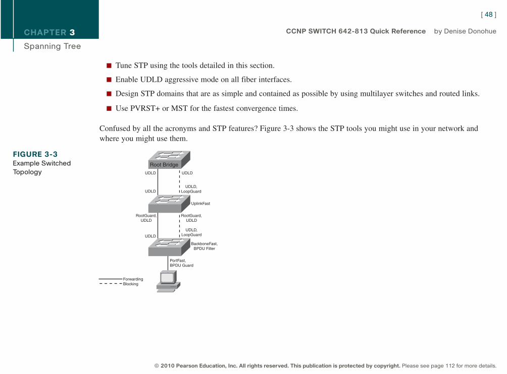
n Tune STP using the tools detailed in this section.
n Enable UDLD aggressive mode on all fiber interfaces.
n Design STP domains that are as simple and contained as possible by using multilayer switches and routed links.
n Use PVRST+ or MST for the fastest convergence times.
Confused by all the acronyms and STP features? Figure 3-3 shows the STP tools you might use in your network andwhere you might use them.
[ 48 ]
© 2010 Pearson Education, Inc. All rights reserved. This publication is protected by copyright. Please see page 112 for more details.
CCNP SWITCH 642-813 Quick Reference by Denise Donohue
FIGURE 3-3Example Switched
TopologyRoot Bridge
UDLD
UDLD
UDLD
UDLD,LoopGuard
RootGuard,UDLD
RootGuard,UDLD
UDLD
UDLD,LoopGuard
BackboneFast,BPDU Filter
PortFast,BPDU Guard
ForwardingBlocking
UplinkFast
9781587140112.qxd 11/23/09 11:35 AM Page 48
CHAPTER 4
InterVLAN Routing
Chapter 4InterVLAN Routing
VLANs divide the network into smaller broadcast domains but also prohibit communication between domains. To enablecommunication between those groups–without also passing broadcasts–routing is used.
InterVLAN Routing Using an External RouterA Layer 2 switch can connect to a router to provide reachability between VLANs. This can be done either via separatephysical links for each VLAN or via a trunk link from the switch to the router. A trunk link is most common and this typeof setup is frequently called Router on a Stick.
When using a trunk link you must create separate subinterfaces on the router’s physical interface—one subinterface foreach VLAN plus one for the native VLAN. This can work with any kind of switch and the implementation is straightfor-ward, but the router becomes a single point of failure for all users, and the trunk link might become congested.
The router’s configuration would look similar to the following:
interface FastEthernet0/1
no ip address
duplex auto
speed auto
!
interface FastEthernet0/1.20
description Voice VLAN
[ 49 ]
© 2010 Pearson Education, Inc. All rights reserved. This publication is protected by copyright. Please see page 112 for more details.
CCNP SWITCH 642-813 Quick Reference by Denise Donohue
9781587140112.qxd 11/23/09 11:35 AM Page 49
CHAPTER 4
InterVLAN Routing
encapsulation dot1Q 20
ip address 10.1.20.1 255.255.255.0
!
interface FastEthernet0/1.99
description Native VLAN
encapsulation dot1Q 99 native
ip address 10.1.99.1 255.255.255.0
!
interface FastEthernet0/1.120
description Data VLAN
encapsulation dot1Q 120
ip address 10.1.120.1 255.255.255.0
InterVLAN Routing Using Multilayer SwitchesA multilayer switch can do both Layer 2 switching and Layer 3 routing between VLANs. This section walks you throughthe switching process and focuses on order of operations. The order in which things happen is extremely important fortwo reasons. First, the order of events is good test material. Second, understanding the processing order allows you toevaluate how the various filtering and forwarding mechanisms interact. (Examples include error checking, access-lists,VLAN access-lists, routing, and QoS.)
The Layer 2 and Layer 3 Forwarding ProcessA multilayer switch does Layer 2 forwarding when the destination MAC address is mapped to one of its interfaces. Thesteps involved in Layer 2 forwarding are as follows:
[ 50 ]
© 2010 Pearson Education, Inc. All rights reserved. This publication is protected by copyright. Please see page 112 for more details.
CCNP SWITCH 642-813 Quick Reference by Denise Donohue
9781587140112.qxd 11/23/09 11:35 AM Page 50
CHAPTER 4
InterVLAN Routing
Input
1. Receive frame
2. Verify frame integrity
3. Apply inbound VLAN ACL (VLAN Access Control List)
4. Look up destination MAC (Media Address Code)
Output
1. Apply outbound VLAN ACL
2. Apply outbound QoS ACL
3. Select output port
4. Place in port queue
5. Rewrite
6. Forward
A multilayer switch does Layer 3 forwarding when the destination MAC address is one of the switch’s own addresses.The steps involved in Layer 3 forwarding are as follows:
Input
1. Receive frame.
2. Verify frame integrity.
3. Apply inbound VLAN ACL.
4. Look up destination MAC.
[ 51 ]
© 2010 Pearson Education, Inc. All rights reserved. This publication is protected by copyright. Please see page 112 for more details.
CCNP SWITCH 642-813 Quick Reference by Denise Donohue
9781587140112.qxd 11/23/09 11:35 AM Page 51
CHAPTER 4
InterVLAN Routing
Routing
1. Apply input ACL
2. Switch if entry is in CEF cache
3. Identify exit interface and next-hop address using routing table
4. Apply output ACL
Output
1. Apply outbound VLAN ACL.
2. Apply outbound QoS ACL.
3. Select output port.
4. Place in interface queue.
5. Rewrite source and destination MAC, IP checksum and frame check sequence, and decrement TTL (Time to Livefield in the IP header).
6. Forward.
Understanding the Switching TableMultilayer switches use Application Specific Integrated Circuits (ASIC) to forward packets at wire speed. The ContentAddressable Memory (CAM) table, used for Layer 2 switching, is created by recording the source MAC address andingress port of each frame. It contains binary values (0 or 1) and must find an exact match to have a hit.
[ 52 ]
© 2010 Pearson Education, Inc. All rights reserved. This publication is protected by copyright. Please see page 112 for more details.
CCNP SWITCH 642-813 Quick Reference by Denise Donohue
9781587140112.qxd 11/23/09 11:35 AM Page 52
CHAPTER 4
InterVLAN Routing
In comparison, Multilayer Switching (MLS) uses aa Ternary Content Addressable Memory (TCAM) table to store infor-mation needed by Layer 3 and higher processing. This might include QoS and ACLs. Values in the TCAM table includeternary values (0, 1, or wildcard). An exact match is not required—the longest match is considered a hit.
MLS InterfacesA multilayer switch can have the following types of interfaces:
n Layer 2 Interface: Either an access port assigned to a VLAN or a trunk port.
n Switch Virtual Interface (SVI): A virtual, software interface for the VLAN itself. Can be either a Layer 2 interfaceor a Layer 3 interface.
n Routed Interface: A physical interface that is not associated with a VLAN and acts like a router port.
SVI Configuration
A default SVI for VLAN 1 is automatically created in the switch. To create an SVI use the command interface vlan#.Configure an IP address on the SVI to make it a Layer 3 interface. SVIs are used to:
n Route or fallback bridge between VLANs.
n Provide a default gateway for users in that VLAN.
n Route traffic into or out of its associated VLAN.
n Provide an IP address for connectivity to the switch itself.
n Provide an interface for routing protocols.
[ 53 ]
© 2010 Pearson Education, Inc. All rights reserved. This publication is protected by copyright. Please see page 112 for more details.
CCNP SWITCH 642-813 Quick Reference by Denise Donohue
9781587140112.qxd 11/23/09 11:35 AM Page 53
CHAPTER 4
InterVLAN Routing
An SVI is considered “up” as long as at least one port in its associated VLAN is active and forwarding. If all ports in theVLAN are down, the interface goes down to avoid creating a routing black hole. You might not want the status of aparticular port (one not connected to a host) to affect the SVI’s status. Some Cisco switches enable you to use the follow-ing command on that interface.
Switch(config-if)# switchport autostate exclude
To configure InterVLAN routing using a Layer 3 SVI, you need to:
n Enable IP routing.
n Create the VLANs.
n Create the SVIs.
n Associate an IP address with each SVI.
n Configure a dynamic routing protocol if needed.
Switch(config)#ip routing
Switch(config)# vlan 3
Switch(config)# interface vlan 3
Switch(config-if)#ip address 10.3.3.3 255.255.255.0
Routed Switch Port Configuration
To configure an interface as a routed port, you must remove the Layer 2 functionality with the no switchport interfacecommand. Then you can add an IP address and configure routing as needed:
sw1(config)# int fa 1/0/5
sw1(config-if)# no switchport
sw1(config-if)# ip address 10.5.5.5 255.255.255.0
[ 54 ]
© 2010 Pearson Education, Inc. All rights reserved. This publication is protected by copyright. Please see page 112 for more details.
CCNP SWITCH 642-813 Quick Reference by Denise Donohue
9781587140112.qxd 11/23/09 11:35 AM Page 54
CHAPTER 4
InterVLAN Routing
To verify your configuration, use the commands show ip interface brief, show interface, or show running-config inter-face int-#.
Understanding Switch Forwarding ArchitecturesPackets entering a router or multilayer switch are handled by one of three types of switching:
n Process Switching: Each packet must be examined by the CPU and handled in software. Slowest method, used inrouters only.
n Fast Switching: CPU process switches the first packet in each flow, then caches that information, and switchessubsequent packets in hardware. Faster than process switching, used in routers and multilayer switches. Also calledroute caching.
n Cisco Express Forwarding (CEF): A table is prebuilt with adjacency information for all destinations in the routingtable. Fastest method, is the default for Cisco routers and multilayer switches. Also called topology-based switching.
CEF SwitchingMultilayer Switching (MLS) is a switch feature that enables the switch to route traffic between VLANs and routed inter-faces in a highly optimized and efficient manner. Cisco Express Forwarding (CEF) is used to facilitate MLS (see Figure4-1). Cisco Express Forwarding (CEF) does the following:
[ 55 ]
© 2010 Pearson Education, Inc. All rights reserved. This publication is protected by copyright. Please see page 112 for more details.
CCNP SWITCH 642-813 Quick Reference by Denise Donohue
9781587140112.qxd 11/23/09 11:35 AM Page 55
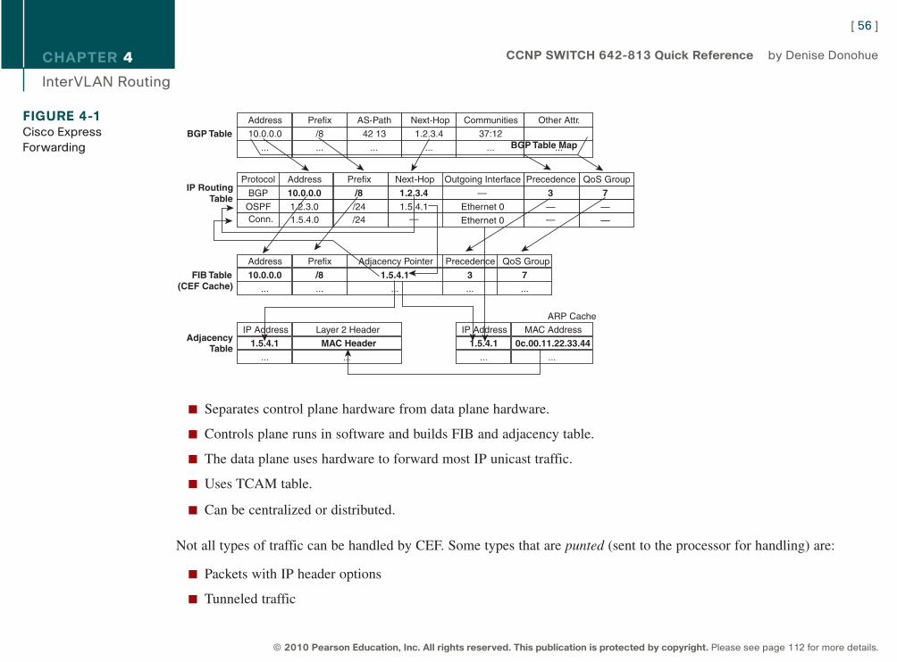
CHAPTER 4
InterVLAN Routing
n Separates control plane hardware from data plane hardware.
n Controls plane runs in software and builds FIB and adjacency table.
n The data plane uses hardware to forward most IP unicast traffic.
n Uses TCAM table.
n Can be centralized or distributed.
Not all types of traffic can be handled by CEF. Some types that are punted (sent to the processor for handling) are:
n Packets with IP header options
n Tunneled traffic
[ 56 ]
© 2010 Pearson Education, Inc. All rights reserved. This publication is protected by copyright. Please see page 112 for more details.
CCNP SWITCH 642-813 Quick Reference by Denise Donohue
FIGURE 4-1Cisco Express
Forwarding
BGP TableAddress Prefix AS-Path Communities Other Attr.Next-Hop
10.0.0.0 /8 42 13 37:121.2.3.4
... ... ... ... ......
IP RoutingTable
Address Prefix
... ...
FIB Table(CEF Cache)
Next-Hop Outgoing InterfaceAddressProtocol
BGP
ARP Cache
Adjacency Pointer
...
1.5.4.1 Ethernet 01.2.3.0OSPF
MAC Address
...
IP Address
...
Layer 2 Header
...
AdjacencyTable
IP Address
...
1.5.4.1 MAC Header
Prefix
/24
Precedence
—
QoS Group
—
—
1.2.3.4 —10.0.0.0 /8 3 7
BGP Table Map
Precedence
...
QoS Group
...
0c.00.11.22.33.441.5.4.1
10.0.0.0 /8 1.5.4.1 3 7
Conn. 1.5.4.0 /24 — Ethernet 0 —
9781587140112.qxd 11/23/09 11:35 AM Page 56
CHAPTER 4
InterVLAN Routing
n 802.3 (IPX) or other unsupported encapsulation types
n Packets with an expiring TTL
n Packets that must be fragmented
Configuring and Troubleshooting CEFBy default, CEF is on and supports per destination load sharing.
To disable CEF
n 4500: Use (config)# no ip cef.
n 3500/3700: On each interface, use (config)# no ip route-cache cef.
n 6550 with policy feature card, distributed FC, and multilayer switch FC: cannot be disabled.
View CEF information with the following:
# show interface fastethernet 2/2 | begin L3
View switching statistics with the following:
# show interface fastethernet 2/2 | include switched
View FIB with the following:
# show ip cef {interface} {detail}
View detailed CEF FIB entry with the following:
# show ip cef fastethernet 2/2 10.0.0.1 detail
[ 57 ]
© 2010 Pearson Education, Inc. All rights reserved. This publication is protected by copyright. Please see page 112 for more details.
CCNP SWITCH 642-813 Quick Reference by Denise Donohue
9781587140112.qxd 11/23/09 11:35 AM Page 57
CHAPTER 4
InterVLAN Routing
Troubleshoot CEF drops with the following:
# show cef drop
Troubleshoot CEF adjacencies with the following:
# show adjacency
[ 58 ]
© 2010 Pearson Education, Inc. All rights reserved. This publication is protected by copyright. Please see page 112 for more details.
CCNP SWITCH 642-813 Quick Reference by Denise Donohue
9781587140112.qxd 11/23/09 11:35 AM Page 58
CHAPTER 5
Implementing High Availability
Chapter 5Implementing High Availability
A highly available network is the goal of every network engineer. Having a highly available network makes the job easierbecause it helps to prevent network outages and minimize downtime.
Components of High AvailabilityThere are five components to high availability: redundancy, technology, people, processes, and tools. The first two can beobtained through network design; the last three are more difficult to implement and control.
RedundancyRedundancy attempts to eliminate single points of failure by providing duplicate devices and links. This costs more, sothe added cost must be balanced against the added benefit. Add redundancy where it will have the most impact on avail-ability, in the core of your network, data center, or e-commerce module. Critical WAN or ISP connections are anotherpossible location.
A redundant network has path diversity with multiple links between multiple devices. It can have geographic diversity,with data centers in multiple sites. Networks frequently have dual core and distribution switches, with dual uplinks toeach. Dual WAN providers, with dual WAN edge routers, are commonly used. Companies can design their networks withconnections to dual Telco central offices and power substations to achieve additional redundancy.
[ 59 ]
© 2010 Pearson Education, Inc. All rights reserved. This publication is protected by copyright. Please see page 112 for more details.
CCNP SWITCH 642-813 Quick Reference by Denise Donohue
9781587140112.qxd 11/23/09 11:35 AM Page 59
CHAPTER 5
Implementing High Availability
TechnologySome of the technologies found in Cisco routers and Layer 3 switches enhance availability by providing routing continu-ity, fast failure detection to trigger a failover, and fast routing convergence. These include:
n Cisco Nonstop Forwarding (NSF)
n Stateful Switchover (SSO)
n Stackwise technology on 3750 switches
n Virtual Switch System (VSS)
n Monitoring tools such as SNMP and Syslog
n IP Service Level Agreement (SLA)
Each of these technologies is discussed in later sections of this chapter.
Some other technological features that enhance availability include server load balancing, firewall stateful failover, andfast routing convergence.
PeopleAlthough the “people” part of high availability is not usually under the control of the network engineer, it is an importantpart of the equation. The following items should be considered:
n Staff work habits: Staff should pay attention to detail, and their work should be reliable and consistent to maketroubleshooting easier.
n Staff skills and technical training: A knowledgeable staff understands the network technologies and configuresdevices correctly. A company lab enables failover scenarios to be tested before incorporating them into the networkand allows network engineers to practice their skills.
[ 60 ]
© 2010 Pearson Education, Inc. All rights reserved. This publication is protected by copyright. Please see page 112 for more details.
CCNP SWITCH 642-813 Quick Reference by Denise Donohue
9781587140112.qxd 11/23/09 11:35 AM Page 60
CHAPTER 5
Implementing High Availability
n Communication and documentation: There should be good communication between teams responsible for thenetwork, security, servers, and applications. There should also be communication with users. Good documentation,readily available, is critical to understanding how the network is designed and how it should behave during a failure.
n Sufficient time to accomplish a task: Not having enough time to accomplish a network-related task leads to impor-tant components, such as testing and documentation, being left out. The design target should be a better than just“adequate” network.
n Align staff with the services they support: This helps ensure clear lines of responsibility for the different segmentsof the network. Be sure to include the people responsible for a segment in the planning for its high availability.
ProcessesCompanies that build repeatable processes and design templates have more cohesive networks and save time in trou-bleshooting problems. Process documentation should include configuration change procedures, failover and lab testingprocedures, and network implementation procedures. These should be regularly reviewed and improved as part of thePPDIOO process.
A lab that reflects the current production network enables thorough testing and validation of such changes as new config-urations and IOS versions and ensures that the staff thoroughly understands network failover processes.
Having a meaningful change control process includes the complete testing of all changes and how they affect failoverwithin the entire network before they are implemented. Changes must be well planned with a roll-back strategy in place.A risk analysis can also help determine if the change is worthwhile.
Network management processes are often overlooked. These should include:
n Capacity audits
n IOS version management
n Corporate best-practice design compliance
[ 61 ]
© 2010 Pearson Education, Inc. All rights reserved. This publication is protected by copyright. Please see page 112 for more details.
CCNP SWITCH 642-813 Quick Reference by Denise Donohue
9781587140112.qxd 11/23/09 11:35 AM Page 61
CHAPTER 5
Implementing High Availability
n Disaster recovery and business continuity plans
n Evaluating the security impact of a proposed change
ToolsA well-designed, highly available network can have a failure without it being noticed by users. It is important to havetools in place to monitor the network and send alerts when a failover occurs. Monitoring can also help spot problems asthey begin to occur, enabling you to be proactive in your network management. There are many third-party tools availablefor this; some IOS tools are discussed in later sections of this chapter.
Good documentation is a critical tool to have. Good documentation includes up-to-date network diagrams with networkaddresses, VLAN information, and interface information. Important servers, applications, and services should be noted.Document not only HOW the network is designed, but also WHY it is designed that way.
Resiliency and High AvailabilityA highly available network is a resilient network. A resilient network employs various methods to allow it to recover andcontinue operating in the event of a failure. Resiliency leads to high availability through the following components:
n Network-level resiliency (the focus of this book): This includes redundant links and redundant devices, but itdoesn’t stop there. Those devices must be configured so they fail between devices, or links, quickly.
n System-level resiliency: This includes redundancy within the hardware, such as dual power supplies, and cold-standby parts, such as extra stackable switches or switch modules. It also includes features within the hardware thatenable fast failover.
n Network management and monitoring: You need to detect a failure immediately and be informed of the actionstaken automatically to remediate it.
[ 62 ]
© 2010 Pearson Education, Inc. All rights reserved. This publication is protected by copyright. Please see page 112 for more details.
CCNP SWITCH 642-813 Quick Reference by Denise Donohue
9781587140112.qxd 11/23/09 11:35 AM Page 62
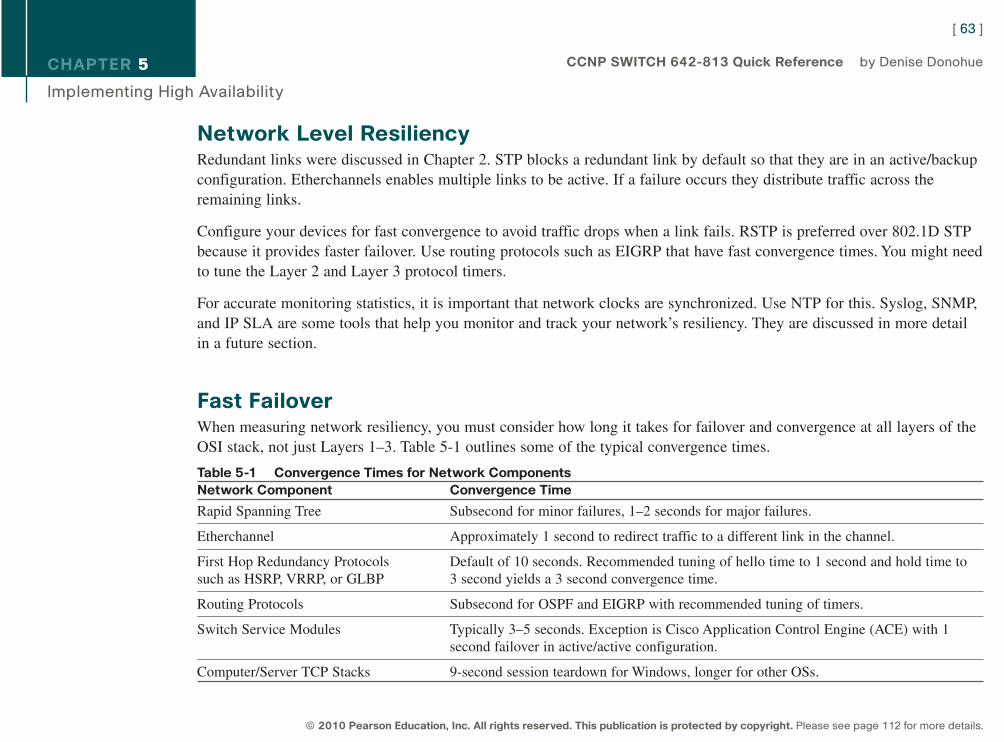
CHAPTER 5
Implementing High Availability
Network Level ResiliencyRedundant links were discussed in Chapter 2. STP blocks a redundant link by default so that they are in an active/backupconfiguration. Etherchannels enables multiple links to be active. If a failure occurs they distribute traffic across theremaining links.
Configure your devices for fast convergence to avoid traffic drops when a link fails. RSTP is preferred over 802.1D STPbecause it provides faster failover. Use routing protocols such as EIGRP that have fast convergence times. You might needto tune the Layer 2 and Layer 3 protocol timers.
For accurate monitoring statistics, it is important that network clocks are synchronized. Use NTP for this. Syslog, SNMP,and IP SLA are some tools that help you monitor and track your network’s resiliency. They are discussed in more detailin a future section.
Fast FailoverWhen measuring network resiliency, you must consider how long it takes for failover and convergence at all layers of theOSI stack, not just Layers 1–3. Table 5-1 outlines some of the typical convergence times.
Table 5-1 Convergence Times for Network ComponentsNetwork Component Convergence Time
Rapid Spanning Tree Subsecond for minor failures, 1–2 seconds for major failures.
Etherchannel Approximately 1 second to redirect traffic to a different link in the channel.
First Hop Redundancy Protocols Default of 10 seconds. Recommended tuning of hello time to 1 second and hold time to such as HSRP, VRRP, or GLBP 3 second yields a 3 second convergence time.
Routing Protocols Subsecond for OSPF and EIGRP with recommended tuning of timers.
Switch Service Modules Typically 3–5 seconds. Exception is Cisco Application Control Engine (ACE) with 1second failover in active/active configuration.
Computer/Server TCP Stacks 9-second session teardown for Windows, longer for other OSs.
[ 63 ]
© 2010 Pearson Education, Inc. All rights reserved. This publication is protected by copyright. Please see page 112 for more details.
CCNP SWITCH 642-813 Quick Reference by Denise Donohue
9781587140112.qxd 11/23/09 11:35 AM Page 63
CHAPTER 5
Implementing High Availability
Optimizing RedundancyYou should be aware that redundancy does not always equal resiliency. Too much redundancy can increase the networkcomplexity to a point that it becomes harder to troubleshoot and actually leads to a less-available network. There are toomany paths for the data to follow, so it becomes less deterministic. The cost is much higher, also.
NSF with SSOLayers 2–4 convergence time is enhanced in Cisco 4500 and 6500 series switches with redundant route processors (RP)by using NSF with SSO. When using this, only one RP is active. The standby RP synchronizes its configuration anddynamic state information (such as CEF, MAC, and FIB tables) with the active RP. When the active RP fails, SSOenables the standby RP to take over immediately. NSF keeps the switch forwarding traffic during the switchover, usingthe existing route and CEF tables. The goal of NSF with SSO is to prevent routing adjacencies from resetting, whichprevents a routing flap. The switchover to the new RP must be completed before routing timers expire, or the router’sneighbors will tear down their adjacency and routing will be disrupted.
When the new RP is up, the old routes are marked as stale, and the RP asks its routing peers to refresh them. Whenrouting is converged, it updates the routing and CEF tables on the switch and the linecards.
NSF is supported with EIGRP, OSPF, ISIS, and BGP. An NSF-capable router supports NSF; an NSF-aware router doesnot support NSF but understands it and continues forwarding traffic during SSO.
Use NSF with SSO in locations where you do not have a duplicate switch for failover, such as at the user access orEnterprise network edge. Otherwise it can actually cause longer convergence. Routing protocols timers can be tuned veryshort to provide fast convergence. With SSO, the switchover to the standby RP might not occur before the tuned routingDead timer expires, and the adjacency would be reset.
[ 64 ]
© 2010 Pearson Education, Inc. All rights reserved. This publication is protected by copyright. Please see page 112 for more details.
CCNP SWITCH 642-813 Quick Reference by Denise Donohue
9781587140112.qxd 11/23/09 11:35 AM Page 64
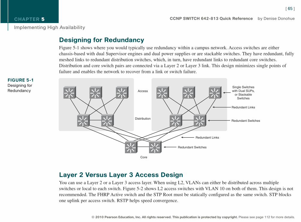
CHAPTER 5
Implementing High Availability
Designing for RedundancyFigure 5-1 shows where you would typically use redundancy within a campus network. Access switches are eitherchassis-based with dual Supervisor engines and dual power supplies or are stackable switches. They have redundant, fullymeshed links to redundant distribution switches, which, in turn, have redundant links to redundant core switches.Distribution and core switch pairs are connected via a Layer 2 or Layer 3 link. This design minimizes single points offailure and enables the network to recover from a link or switch failure.
Layer 2 Versus Layer 3 Access DesignYou can use a Layer 2 or a Layer 3 access layer. When using L2, VLANs can either be distributed across multipleswitches or local to each switch. Figure 5-2 shows L2 access switches with VLAN 10 on both of them. This design is notrecommended. The FHRP Active switch and the STP Root must be statically configured as the same switch. STP blocksone uplink per access switch. RSTP helps speed convergence.
[ 65 ]
© 2010 Pearson Education, Inc. All rights reserved. This publication is protected by copyright. Please see page 112 for more details.
CCNP SWITCH 642-813 Quick Reference by Denise Donohue
FIGURE 5-1Designing for
Redundancy Access
Distribution
Core
Redundant Switches
Redundant Links
Redundant Switches
Redundant Links
Single Switcheswith Dual SUPs,
or StackableSwitches
9781587140112.qxd 11/23/09 11:35 AM Page 65
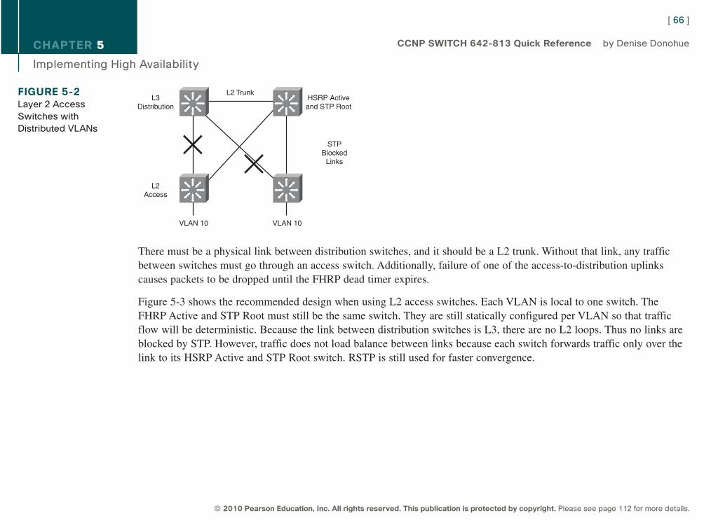
CHAPTER 5
Implementing High Availability
There must be a physical link between distribution switches, and it should be a L2 trunk. Without that link, any trafficbetween switches must go through an access switch. Additionally, failure of one of the access-to-distribution uplinkscauses packets to be dropped until the FHRP dead timer expires.
Figure 5-3 shows the recommended design when using L2 access switches. Each VLAN is local to one switch. TheFHRP Active and STP Root must still be the same switch. They are still statically configured per VLAN so that trafficflow will be deterministic. Because the link between distribution switches is L3, there are no L2 loops. Thus no links areblocked by STP. However, traffic does not load balance between links because each switch forwards traffic only over thelink to its HSRP Active and STP Root switch. RSTP is still used for faster convergence.
[ 66 ]
© 2010 Pearson Education, Inc. All rights reserved. This publication is protected by copyright. Please see page 112 for more details.
CCNP SWITCH 642-813 Quick Reference by Denise Donohue
FIGURE 5-2Layer 2 Access
Switches with
Distributed VLANs
STPBlocked
Links
VLAN 10VLAN 10
L2 TrunkL3
Distribution
L2Access
HSRP Activeand STP Root
9781587140112.qxd 11/23/09 11:35 AM Page 66
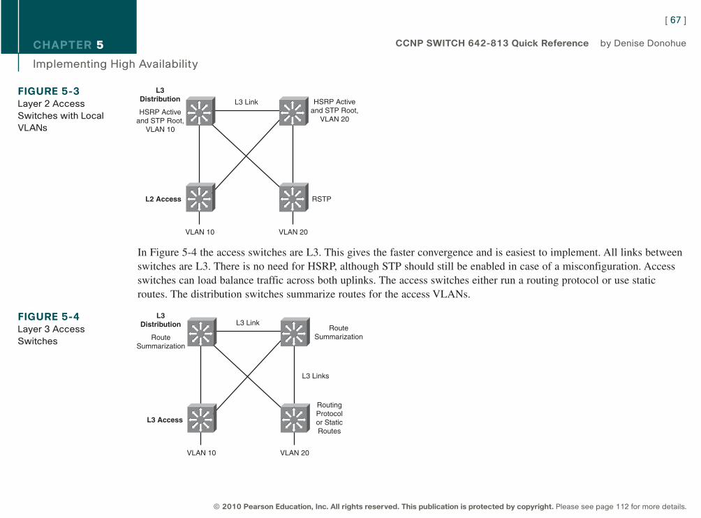
CHAPTER 5
Implementing High Availability
In Figure 5-4 the access switches are L3. This gives the faster convergence and is easiest to implement. All links betweenswitches are L3. There is no need for HSRP, although STP should still be enabled in case of a misconfiguration. Accessswitches can load balance traffic across both uplinks. The access switches either run a routing protocol or use staticroutes. The distribution switches summarize routes for the access VLANs.
[ 67 ]
© 2010 Pearson Education, Inc. All rights reserved. This publication is protected by copyright. Please see page 112 for more details.
CCNP SWITCH 642-813 Quick Reference by Denise Donohue
FIGURE 5-3Layer 2 Access
Switches with Local
VLANs
RSTPL2 Access
VLAN 20VLAN 10
L3 Link
L3Distribution HSRP Active
and STP Root,VLAN 20
HSRP Activeand STP Root,
VLAN 10
FIGURE 5-4Layer 3 Access
Switches
RoutingProtocolor StaticRoutes
L3 Access
VLAN 20VLAN 10
L3 Link
L3 Links
L3Distribution Route
SummarizationRouteSummarization
9781587140112.qxd 11/23/09 11:35 AM Page 67
CHAPTER 5
Implementing High Availability
Using Nonchassis Based Access SwitchesUsing more than one stand-alone switch, such as the Cisco 3560 or 3750, in an access closet requires special designconsideration. You can either daisy-chain the switches or use the Cisco Stackwise technology. When you daisy-chainswitches, the top and bottom members of the chain typically uplink to one distribution switch each. You must add a link(or loopback cable) between the top and bottom switch. Otherwise, a failure in the link between two access switchesmight cause return traffic to be blackholed. Alternatively you can configure the link between the distribution switches asan L2 trunk.
Stackwise switches enable you to manage each group of access switches as one. Two stack member switches uplink tothe distribution switches. Special cables connect the switches, and you should still connect the top and bottom membersof the stack using a Stackwise cable. The link between distribution switches can then be an L3 link without worry ofblackholing return traffic.
Network Management for High AvailabilityNetwork administrators use network management tools:
n To verify network performance
n To characterize, or baseline, network performance
n To understand amount and direction of traffic flow within the network
n To troubleshoot network problems
[ 68 ]
© 2010 Pearson Education, Inc. All rights reserved. This publication is protected by copyright. Please see page 112 for more details.
CCNP SWITCH 642-813 Quick Reference by Denise Donohue
9781587140112.qxd 11/23/09 11:35 AM Page 68
CHAPTER 5
Implementing High Availability
SyslogCisco devices produce system logging (or syslog) messages that can be output to the device console, VTY connection,system buffer, or remote syslog server. If sent to a syslog server, messages are sent on UDP port 514. You are probablyfamiliar with the syslog message %SYS-5-CONFIG_I: Configured from console by console, for instance. A syslogmessage always starts with the percent sign and has the following format:
%FACILTY-SUBFACILITY-SEVERITY-MNEMONIC: message text
Each portion of a syslog message has a specific meaning:
n FACILITY-SUBFACILITY: This tells the protocol, module, or process that generated the message. Some examplesare SYS for the operating system, OSPF, IF for an interface, and IP.
n SEVERITY: A number from 0 to 7 designating the importance of the action reported. The levels are:
n Emergency: 0
n Alert: 1
n Critical: 2
n Error: 3
n Warning: 4
n Notice: 5
n Informational: 6
n Debugging: 7
n MNEMONIC: A code that identifies the action reported.
n A plain-text description of the event that triggered the syslog message.
[ 69 ]
© 2010 Pearson Education, Inc. All rights reserved. This publication is protected by copyright. Please see page 112 for more details.
CCNP SWITCH 642-813 Quick Reference by Denise Donohue
9781587140112.qxd 11/23/09 11:35 AM Page 69
CHAPTER 5
Implementing High Availability
SNMPAn SNMP manager collects information from SNMP agents residing on network devices, either through regular pollingor by event-generated traps. The information is stored on the local device in a Management Information Base (MIB).Access to the MIB is controlled by SNMP community strings. Access can be read-only (RO) or read-write(RW).
There are three versions of SNMP. Versions 1 and 2 send the community strings in clear text. They cannot authenticatethe source of a message or encrypt a message. Therefore they should be used only for read-only access. SNMPv3 addsthree security levels:
n noAuthNoPriv: Neither authenticates nor encrypts
n authNoPriv: Authenticates the sender but does not encrypt the message
n authPriv: Both authenticates the sender and encrypts the message
The following configuration creates a standard access list that allows only traffic sourced from the host at 10.1.1.1. Twocommunity-strings are created, “ccnp” for read-only access and “c1sc0” for read-write access. Read-write access ispermitted only from the host specified in access list 1. Next, the SNMP server address is given, along with the commandto send traps messages to that server. Because SNMP version 3 is used, the username “admin” is needed.
sw1(config)# access-list 1 permit 10.1.1.1
sw1(config)# snmp-server community ccnp ro
sw1(config)# snmp-server community c1sc0 rw 1
sw1(config)# snmp-server host 10.1.1.2 traps admin
IP SLAIP SLA is a feature that enables a Cisco router or switch to simulate specific types of traffic and send it to a receiver,
[ 70 ]
© 2010 Pearson Education, Inc. All rights reserved. This publication is protected by copyright. Please see page 112 for more details.
CCNP SWITCH 642-813 Quick Reference by Denise Donohue
9781587140112.qxd 11/23/09 11:35 AM Page 70
CHAPTER 5
Implementing High Availability
called a responder. IP SLA probes can simulate various types of traffic, such as HTTP, FTP, DHCP, UDP jitter, UDPecho, HTTP, TCP connect, ICMP echo, ICMP path echo, ICMP path jitter, and DNS, and can report statistics such aspath jitter. It has highly granular application configuration options such as TCP/UDP port numbers, TOS byte, and IPprefix bits. This is useful for measuring application performance end-to-end across your network. It can also be used totrack reachability and then decrement HSRP priority values or bring up secondary links. Additionally, IP SLA can also beused as a measure of reliability and continuous availability. SNMP traps can be generated from events such as connectionloss, timeout, roundtrip time threshold, average jitter threshold, one-way packet loss, one-way jitter, and one-way latency.
To enable IP SLA, configure the source to send the required type of data probes. The receiver can be a computer, or it canbe another Cisco device. The configuration of a Cisco responder is simple. Use the global ip sla responder command.One benefit of using a Cisco device as the responder is that it can add time stamps to help measure latency and jitter.These time stamps take into account the device processing time so that the measurement reflects only network latency.
The configuration of the IP SLA source is more complex. You must create a monitor session, list the traffic type, respon-der IP address, and any other desired variables such as DSCP value. Then you schedule the probes. Optionally configuretracking using the IP SLA session. The following commands set up an IP SLA session that measures UDP jitter for avoice port. Traffic is sent every 120 seconds, starting when the last command is given and continues until it is manuallystopped.
sw1(config)#ip sla 1
sw1(config-ip-sla)#udp-jitter 10.1.1.3 65422 codec g729a
sw1(config-ip-sla-jitter)#frequency 120
sw1(config-ip-sla-jitter)#exit
sw1(config)#ip sla schedule 1 life forever start-time now
[ 71 ]
© 2010 Pearson Education, Inc. All rights reserved. This publication is protected by copyright. Please see page 112 for more details.
CCNP SWITCH 642-813 Quick Reference by Denise Donohue
9781587140112.qxd 11/23/09 11:35 AM Page 71
CHAPTER 6
First Hop Redundancy
Chapter 6First Hop Redundancy
Specifying a default gateway leads to a single point of failure. Proxy Address Resolution Protocol (ARP) is one methodfor hosts to dynamically discover gateways, but it has issues in a highly available environment. With Proxy ARP:
n Hosts ARP for all destinations, even remote.
n Router responds with its MAC.
n Problem: Slow failover because ARP entries take minutes to timeout.
Instead of making the host responsible for choosing a new gateway, router redundancy protocols enable two or morerouters to support a shared MAC address. If the primary router is lost, the backup router assumes control of trafficforwarded to that MAC. This section refers to routers but includes those multilayer switches that can also implementLayer 3 redundancy.
Hot Standby Router ProtocolHot Standby Router Protocol (HSRP) is a Cisco proprietary protocol.
With HSRP, two or more devices support a virtual router with a fictitious MAC address and unique IP address. Hosts usethis IP address as their default gateway and the MAC address for the Layer 2 header. The virtual router’s MAC address is0000.0c07.ACxx, in which xx is the HSRP group. Multiple groups (virtual routers) are allowed.
[ 72 ]
© 2010 Pearson Education, Inc. All rights reserved. This publication is protected by copyright. Please see page 112 for more details.
CCNP SWITCH 642-813 Quick Reference by Denise Donohue
9781587140112.qxd 11/23/09 11:35 AM Page 72
CHAPTER 6
First Hop Redundancy
The Active router forwards traffic. The Standby is backup. The standby monitors periodic hellos (multicast to 224.0.0.2,UDP port 1985) to detect a failure of the active router. On failure, the standby device starts answering messages sent tothe IP and MAC addresses of the virtual router.
The active router is chosen because it has the highest HSRP priority (default priority is 100). In case of a tie, the routerwith the highest configured IP address wins the election. A new router with a higher priority does not cause an electionunless it is configured to preempt—that is, take over from a lower priority router. Configuring a router to preempt alsoensures that the highest priority router regains its active status if it goes down but then comes back online again.
Interface tracking reduces the active router’s priority if a specified circuit is down. This enables the standby router to takeover even though the active router is still up.
HSRP StatesHSRP devices move between these states:
n Initial: HSRP is not running.
n Learn: The router does not know the virtual IP address and is waiting to hear from the active router.
n Listen: The router knows the IP and MAC of the virtual router, but it is not the active or standby router.
n Speak: Router sends periodic HSRP hellos and participates in the election of the active router.
n Standby: Router monitors hellos from active router and assumes responsibility if active router fails.
n Active: Router forwards packets on behalf of the virtual router.
[ 73 ]
© 2010 Pearson Education, Inc. All rights reserved. This publication is protected by copyright. Please see page 112 for more details.
CCNP SWITCH 642-813 Quick Reference by Denise Donohue
Note:The Learn state is notactually seen in debugsof HSRP.
9781587140112.qxd 11/23/09 11:35 AM Page 73
CHAPTER 6
First Hop Redundancy
Configuring HSRPTo begin configuring HSRP, use the standby group-number ip virtual-IP-address command in interface configurationmode. Routers in the same HSRP group must belong to the same subnet/virtual LAN (VLAN.) Give this command underthe interface connecting to that subnet or VLAN. For instance, use the following to configure the router as a member ofHSRP group 39 with virtual router IP address 10.0.0.1:
Router(config-if)# standby 39 ip 10.0.0.1
HSRP authentication helps prevent unauthorized routers from seeing user traffic:
Router(config-if)# stand 2 authentication md5 key-string cisco
Tune HSRP with four options: Priority, Preempt, Timers, and Interface Tracking.
Manually select the active router by configuring its priority higher than the default of 100:
Router(config-if)# standby 39 priority 150
Along with configuring priority, configure preempt to enable a router to take over if the active router has lower priority,as shown in the following commands. This helps lead to a predictable data path through the network. The secondcommand shown delays preemption until the router or switch has fully booted and the routing protocol has converged.Time how long it takes to boot and add 50 percent to get the delay value in seconds:
Router(config-if)# standby 39 preempt
Router(config-if)# standby 39 preempt delay minimum 90
Speed convergence by changing the hello and hold times. The following sets the hello interval to 1 second and the holdtime to 3 seconds. They can be set between 1–255 seconds (the default hello is 3 seconds and hold time is 10 seconds):
Router(config-if)# standby 39 timers 1 3
[ 74 ]
© 2010 Pearson Education, Inc. All rights reserved. This publication is protected by copyright. Please see page 112 for more details.
CCNP SWITCH 642-813 Quick Reference by Denise Donohue
9781587140112.qxd 11/23/09 11:35 AM Page 74
CHAPTER 6
First Hop Redundancy
Tracking an interface can trigger an election if the active router is still up but a critical interface (such as the one to theInternet) is down. In the following, if serial 1/0/0 is down, the router’s HSRP priority is decremented by 100 (the defaultvalue to decrement is 10):
Router(config-if)# standby 39 track s1/0/0 100
Another way to track an indirect connection is to use IP SLA (described in Chapter 5). With IP SLA tracking, HSRP canfailover to the standby router if any connection on the path to a remote location fails or exceeds link-quality thresholds.The following sample configuration shows how to add tracking an IP SLA session number 5 to an existing HSRP inter-face configuration.
Router(config)#ip sla 5
Router(config-ip-sla)# udp-jitter 172.17.1.2 16000
Router(config)#track 10 rtr 5
Router(config-if)# int fa 1/0/15
Router(config-if)# stand 2 track 10 decrement 50
Multiple HSRP standby groups can be configured, and the same router can be active for some groups and standby forothers by adjusting priorities. You can have a maximum of 255 groups. When using Layer 3 switches, configure the sameswitch as the primary HSRP router and the Spanning Tree root.
Virtual Router Redundancy ProtocolVirtual Router Redundancy Protocol (VRRP) is similar to HSRP, but it is an open standard (RFC 2338). Two or moredevices act as a virtual router. With VRRP, however, the IP address used can be either a virtual one or the actual IPaddress of the primary router. VRRP is supported only on Cisco 4500 and 6500 series switches.
[ 75 ]
© 2010 Pearson Education, Inc. All rights reserved. This publication is protected by copyright. Please see page 112 for more details.
CCNP SWITCH 642-813 Quick Reference by Denise Donohue
Note:The standby router mustbe configured with thepreempt command for itto take control.
9781587140112.qxd 11/23/09 11:35 AM Page 75
CHAPTER 6
First Hop Redundancy
The VRRP Master router forwards traffic. The master is chosen because it owns the real address, or it has the highestpriority. (The default is 100.) If a real address is supported, the owner of real address must be master. A Backup routertakes over if the master fails, and there can be multiple backup routers. They monitor periodic hellos multicast by themaster to 224.0.0.18, using UDP port 112, to detect a failure of the master router.
Multiple VRRP groups are allowed, just as with HSRP.
Routers in the same VRRP group must belong to the same subnet/VLAN. To enable VRRP, give this command vrrpgroup-number ip virtual-IP-address under the interface connecting to that subnet or VLAN:
Router(config-if) # vrrp 39 ip 10.0.0.1
Control the master and backup elections by configuring priority values from 1–255. If a master VRRP router is shutdown, it advertises a priority of 0. This triggers the backup routers to hold an election without waiting for the master’shellos to time out.
Router(config-if)# vrrp 39 priority 175
VRRP uses the following timers:
n Advertisement, or hello, interval in seconds. Default is 1 second.
n Master down interval. Equals 3 x advertisement interval plus skew time. Similar to a hold or dead timer.
n Skew time. (256–priority) / 256. This is meant to ensure that the highest priority backup router becomes masterbecause higher priority routers have shorter master down intervals.
To change the timers on the master, use the following command because it is the router that advertises the hellos:
Router(config-if)# vrrp 39 timers advertise 5
[ 76 ]
© 2010 Pearson Education, Inc. All rights reserved. This publication is protected by copyright. Please see page 112 for more details.
CCNP SWITCH 642-813 Quick Reference by Denise Donohue
9781587140112.qxd 11/23/09 11:35 AM Page 76
CHAPTER 6
First Hop Redundancy
To change the timers on the backup routers, use the following command because they hear the hellos from the master:
Router(config-if)# vrrp 39 timers learn
VRRP cannot track interfaces but can track IP SLA object groups.
GLBPOne issue with both HSRP and VRRP is that only the primary router is in use; the others must wait for the primary to failbefore they are used. These two protocols use groups to get around that limitation. However, Gateway Load BalancingProtocol (GLBP) enables the simultaneous use of up to four gateways, thus maximizing bandwidth. With GLBP, there isstill one virtual IP address. However, each participating router has a virtual MAC address, and different routers’ virtualMAC addresses are sent in answer to ARPs for the virtual IP address. GLBP can also use groups up to a maximum of1024 per physical interface. GLBP is supported only on Cisco 4500 and 6500 series switches.
The load sharing is done in one of three ways:
n Weighted load balancing: Traffic is balanced proportional to a configured weight.
n Host-dependent load balancing: A given host always uses the same router.
n Round-robin load balancing: Each router MAC is used to respond to ARP requests in turn.
GLBP routers elect an Active Virtual Gateway (AVG). It is the only router to respond to ARPs. It uses this capacity tobalance the load among the GLBP routers. The highest priority router is the AVG; the highest configured IP address isused in case of a tie.
[ 77 ]
© 2010 Pearson Education, Inc. All rights reserved. This publication is protected by copyright. Please see page 112 for more details.
CCNP SWITCH 642-813 Quick Reference by Denise Donohue
9781587140112.qxd 11/23/09 11:35 AM Page 77
CHAPTER 6
First Hop Redundancy
The actual router used by a host is its Active Virtual Forwarder (AVF). GLBP group members multicast hellos every 3seconds to IP address 224.0.0.102, UDP port 3222. If one router goes down, another router answers for its MAC address.
Configure GLBP with the interface command glbp group-number ip virtual-IP-address, as shown:
Router(config-if)# glbp 39 ip 10.0.0.1
To ensure deterministic elections, each router can be configured with a priority. The default priority is 100:
Router(config-if)# glbp 39 priority 150
Hello and hold (or dead) timers can be configured for each interface with the command glbp group-number timers[msec] hello-time [msec] hold-time. Values are in seconds unless the msec keyword is used.
GLBP can also track interfaces just as with HSRP. If a tracked interface goes down, another router answers for the firstrouter’s MAC address.
Planning Router Redundancy ImplementationBefore configuring first-hop redundancy, determine which protocol is best in your network. If you have the same VLANon multiple access switches, use HSRP or VRRP. If you use local VLANs, contained to a single switch, GLBP is anoption.
Before configuring HSRP or VRRP on a multilayer switch, determine which switch is the root bridge for each VLAN.The root bridge should be the active HSRP/VRRP router. Determine priorities to be used, and whether you need trackingor timer adjustment.
After your implementation, verify and test. To view the switch’s standby status, use the show standby interface interfacecommand or show standby brief. To monitor standby activity, use the debug standby command.
[ 78 ]
© 2010 Pearson Education, Inc. All rights reserved. This publication is protected by copyright. Please see page 112 for more details.
CCNP SWITCH 642-813 Quick Reference by Denise Donohue
9781587140112.qxd 11/23/09 11:35 AM Page 78
CHAPTER 7
Campus Network Security
Chapter 7Campus Network Security
Attention has traditionally been paid to network perimeter security, such as firewall, and to mitigating Layer 3 attacks.However, networks must be protected against Layer 2 attacks, too. These are launched from devices inside the network byeither a rogue device or a legitimate device that has been compromised. Rogue devices might be placed maliciously ormight just be connected to an access switch by an employee wanting more switch port or wireless access. They include:
n Wireless routers or hubs
n Access switches
n Hubs
A switch might become the Spanning Tree root bridge and disrupt user traffic. Use root guard and bpdu guardcommands to prevent this. (Spanning Tree security is discussed later in this chapter.)
The following are four typical types of attacks against a switched network:
n MAC address-based attacks: MAC address flooding
n VLAN-based attacks: VLAN hopping and attacks against devices on the same VLAN
n Spoofing attacks: DHCP spoofing, MAC spoofing, Address Resolution Protocol (ARP) spoofing, and SpanningTree attacks
n Attacks against the switch: Cisco Discovery Protocol (CDP) manipulation, Telnet attacks, and Secure Shell (SSH)attacks
[ 79 ]
© 2010 Pearson Education, Inc. All rights reserved. This publication is protected by copyright. Please see page 112 for more details.
CCNP SWITCH 642-813 Quick Reference by Denise Donohue
9781587140112.qxd 11/23/09 11:35 AM Page 79
CHAPTER 7
Campus Network Security
MAC Address-Based AttacksCommon MAC address-based attacks rely on flooding the CAM table and can be mitigated by using port security andport-based authentication.
MAC Address Flooding In a MAC address flooding attack, the attacker fills the switch’s Content Addressable Memory (CAM) table with invalidMAC addresses. After the table is full, all traffic with an address not in the table is flooded out all interfaces. This has twobad effects: more traffic on the LAN and more work for the switch. This can also cause the CAM tables of adjacentswitches to overflow. Additionally, the intruder’s traffic is also flooded, so they have access to more ports than they wouldnormally have. After the attack stops, CAM entries age out and life returns to normal. However, meanwhile the attackermight have captured a significant amount of data.
Port security and port-based authentication can help mitigate MAC address attacks.
Port SecurityPort security limits the number of MAC addresses allowed per port and can also limit which MAC addresses are allowed.Allowed MAC addressed can be manually configured or the switch can sticky learn them. Table 7-1 lists port securitycommands; these are given at the interface.
[ 80 ]
© 2010 Pearson Education, Inc. All rights reserved. This publication is protected by copyright. Please see page 112 for more details.
CCNP SWITCH 642-813 Quick Reference by Denise Donohue
9781587140112.qxd 11/23/09 11:35 AM Page 80
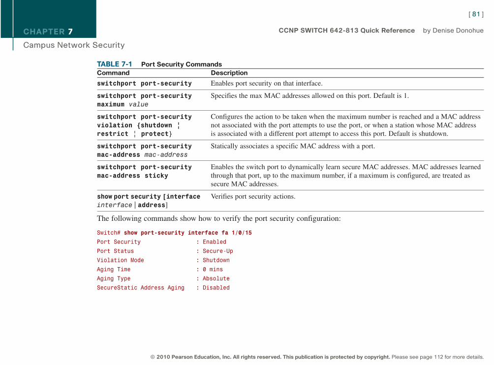
CHAPTER 7
Campus Network Security
TABLE 7-1 Port Security CommandsCommand Description
switchport port-security Enables port security on that interface.
switchport port-security Specifies the max MAC addresses allowed on this port. Default is 1.maximum value
switchport port-security Configures the action to be taken when the maximum number is reached and a MAC addressviolation {shutdown | not associated with the port attempts to use the port, or when a station whose MAC addressrestrict | protect} is associated with a different port attempt to access this port. Default is shutdown.
switchport port-security Statically associates a specific MAC address with a port.mac-address mac-address
switchport port-security Enables the switch port to dynamically learn secure MAC addresses. MAC addresses learnedmac-address sticky through that port, up to the maximum number, if a maximum is configured, are treated as
secure MAC addresses.
show port security [interface Verifies port security actions.interface | address]
The following commands show how to verify the port security configuration:
Switch# show port-security interface fa 1/0/15
Port Security : Enabled
Port Status : Secure-Up
Violation Mode : Shutdown
Aging Time : 0 mins
Aging Type : Absolute
SecureStatic Address Aging : Disabled
[ 81 ]
© 2010 Pearson Education, Inc. All rights reserved. This publication is protected by copyright. Please see page 112 for more details.
CCNP SWITCH 642-813 Quick Reference by Denise Donohue
9781587140112.qxd 11/23/09 11:35 AM Page 81
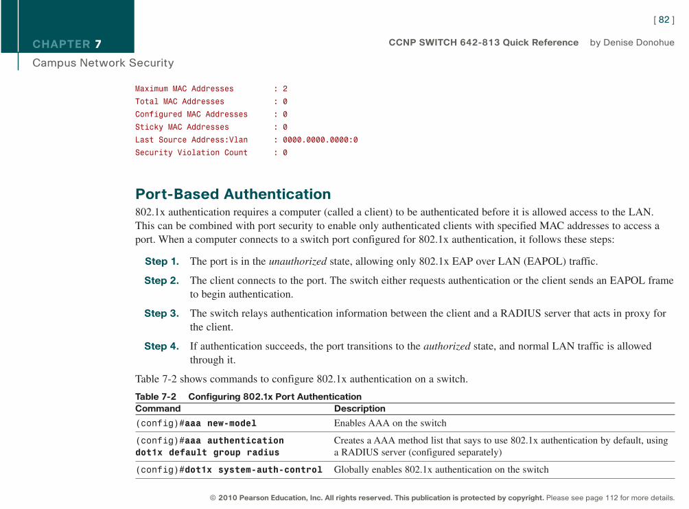
CHAPTER 7
Campus Network Security
Maximum MAC Addresses : 2
Total MAC Addresses : 0
Configured MAC Addresses : 0
Sticky MAC Addresses : 0
Last Source Address:Vlan : 0000.0000.0000:0
Security Violation Count : 0
Port-Based Authentication802.1x authentication requires a computer (called a client) to be authenticated before it is allowed access to the LAN.This can be combined with port security to enable only authenticated clients with specified MAC addresses to access aport. When a computer connects to a switch port configured for 802.1x authentication, it follows these steps:
Step 1. The port is in the unauthorized state, allowing only 802.1x EAP over LAN (EAPOL) traffic.
Step 2. The client connects to the port. The switch either requests authentication or the client sends an EAPOL frameto begin authentication.
Step 3. The switch relays authentication information between the client and a RADIUS server that acts in proxy forthe client.
Step 4. If authentication succeeds, the port transitions to the authorized state, and normal LAN traffic is allowedthrough it.
Table 7-2 shows commands to configure 802.1x authentication on a switch.
Table 7-2 Configuring 802.1x Port AuthenticationCommand Description
(config)#aaa new-model Enables AAA on the switch
(config)#aaa authentication Creates a AAA method list that says to use 802.1x authentication by default, using dot1x default group radius a RADIUS server (configured separately)
(config)#dot1x system-auth-control Globally enables 802.1x authentication on the switch
[ 82 ]
© 2010 Pearson Education, Inc. All rights reserved. This publication is protected by copyright. Please see page 112 for more details.
CCNP SWITCH 642-813 Quick Reference by Denise Donohue
9781587140112.qxd 11/23/09 11:35 AM Page 82
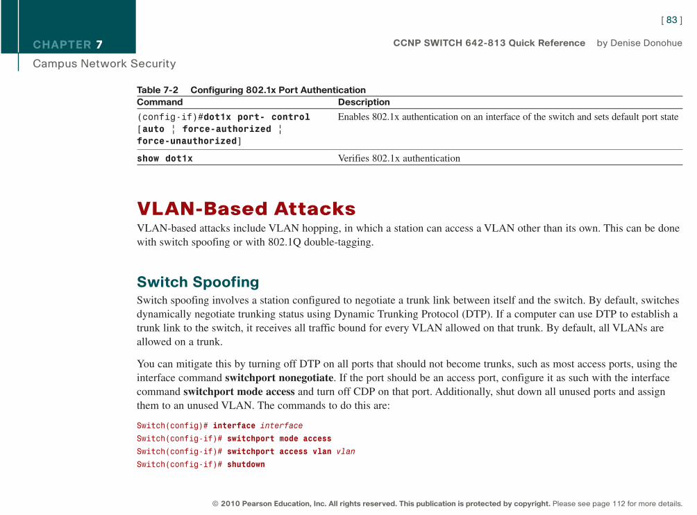
CHAPTER 7
Campus Network Security
Table 7-2 Configuring 802.1x Port AuthenticationCommand Description
(config-if)#dot1x port- control Enables 802.1x authentication on an interface of the switch and sets default port state[auto | force-authorized |
force-unauthorized]
show dot1x Verifies 802.1x authentication
VLAN-Based AttacksVLAN-based attacks include VLAN hopping, in which a station can access a VLAN other than its own. This can be donewith switch spoofing or with 802.1Q double-tagging.
Switch SpoofingSwitch spoofing involves a station configured to negotiate a trunk link between itself and the switch. By default, switchesdynamically negotiate trunking status using Dynamic Trunking Protocol (DTP). If a computer can use DTP to establish atrunk link to the switch, it receives all traffic bound for every VLAN allowed on that trunk. By default, all VLANs areallowed on a trunk.
You can mitigate this by turning off DTP on all ports that should not become trunks, such as most access ports, using theinterface command switchport nonegotiate. If the port should be an access port, configure it as such with the interfacecommand switchport mode access and turn off CDP on that port. Additionally, shut down all unused ports and assignthem to an unused VLAN. The commands to do this are:
Switch(config)# interface interface
Switch(config-if)# switchport mode access
Switch(config-if)# switchport access vlan vlan
Switch(config-if)# shutdown
[ 83 ]
© 2010 Pearson Education, Inc. All rights reserved. This publication is protected by copyright. Please see page 112 for more details.
CCNP SWITCH 642-813 Quick Reference by Denise Donohue
9781587140112.qxd 11/23/09 11:35 AM Page 83
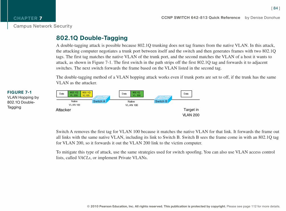
CHAPTER 7
Campus Network Security
802.1Q Double-TaggingA double-tagging attack is possible because 802.1Q trunking does not tag frames from the native VLAN. In this attack,the attacking computer negotiates a trunk port between itself and the switch and then generates frames with two 802.1Qtags. The first tag matches the native VLAN of the trunk port, and the second matches the VLAN of a host it wants toattack, as shown in Figure 7-1. The first switch in the path strips off the first 802.1Q tag and forwards it to adjacentswitches. The next switch forwards the frame based on the VLAN listed in the second tag.
The double-tagging method of a VLAN hopping attack works even if trunk ports are set to off, if the trunk has the sameVLAN as the attacker.
Switch A removes the first tag for VLAN 100 because it matches the native VLAN for that link. It forwards the frame outall links with the same native VLAN, including its link to Switch B. Switch B sees the frame come in with an 802.1Q tagfor VLAN 200, so it forwards it out the VLAN 200 link to the victim computer.
To mitigate this type of attack, use the same strategies used for switch spoofing. You can also use VLAN access controllists, called VACLs, or implement Private VLANs.
[ 84 ]
© 2010 Pearson Education, Inc. All rights reserved. This publication is protected by copyright. Please see page 112 for more details.
CCNP SWITCH 642-813 Quick Reference by Denise Donohue
FIGURE 7-1VLAN Hopping by
802.1Q Double-
TaggingAttacker Target in
VLAN 200
NativeVL AN 100
Native
VL AN 100
Data
Switch A Switch B
Data802.1QVL 200
Data 802.1QVL 200
802.1QVL100
9781587140112.qxd 11/23/09 11:35 AM Page 84
CHAPTER 7
Campus Network Security
VACLsCisco switches support of various kinds of ACLs:
n Traditional Router ACL (RACL)
n QoS ACL
n VACL
VLAN access control lists (VACL) are similar to route-maps because they are composed of statements that contain matchand set conditions. In a VACL, the “set” conditions are called “actions.” Actions include forward, drop, and redirect.Like route-maps, VACL statements are numbered for ordering. After configuration, VACLs are applied to traffic to speci-fied VLANs.
The following is a sample VACL that instructs the switch to drop traffic matching ACL 101 (not shown) and forward allother traffic:
Switch(config)# vlan access-map Drop101 10
Switch(config-access-map)# match ip address 101
Switch(config-access-map)# action drop
!
Switch(config-access-map)# vlan access-map Drop101 20
Switch(config-access-map)# action forward
!
Switch(config)# vlan filter Drop101 vlan-list 10
To view VACL settings, use the commands show vlan access-map vacl_name or show vlan filter access-mapvacl_name.
[ 85 ]
© 2010 Pearson Education, Inc. All rights reserved. This publication is protected by copyright. Please see page 112 for more details.
CCNP SWITCH 642-813 Quick Reference by Denise Donohue
9781587140112.qxd 11/23/09 11:35 AM Page 85
CHAPTER 7
Campus Network Security
Private VLANsPrivate VLANs (PVLAN) enable large companies or service providers to isolate users into separate multiaccess domains.Using a VLAN for each group is not scalable. For instance, the switch’s maximum VLANs would limit the number ofcustomers an ISP can have. Each VLAN requires a separate IP subnet, which could also be a limiting factor.
PVLANs divide a VLAN into secondary VLANs, letting you isolate a set of ports from other ports within the sameVLAN. There are two types of secondary VLANs:
n Community VLANs: Ports can communicate with other ports in the same community VLAN.n Isolated VLANs: Ports cannot communicate with each other.
Ports within a private VLAN can be one of three types:
n Community: Communicates with other community ports and with promiscuous ports
n Isolated: Communicates only with promiscuous ports
n Promiscuous: Communicates with all ports
Table 7-3 shows the commands to configure a primary private VLAN, secondary PVLANs, and their associated ports.
Table 7-3 Configuring Private VLANsCommand Description
vlan vlan-id Enters VLAN configuration mode.
private-vlan {community | Configures the VLAN as a private VLAN and specifies the type. Repeat this isolated | primary} command to configure all primary and secondary VLANs.
vlan primary-vlan-id Enters configuration mode for the primary VLAN.
[ 86 ]
© 2010 Pearson Education, Inc. All rights reserved. This publication is protected by copyright. Please see page 112 for more details.
CCNP SWITCH 642-813 Quick Reference by Denise Donohue
9781587140112.qxd 11/23/09 11:35 AM Page 86
CHAPTER 7
Campus Network Security
Table 7-3 Configuring Private VLANsCommand Description
private-vlan association Associates secondary VLANs with the primary one. Separate the secondary VLAN secondary_vlan_list numbers with a comma, no spaces.
switchport mode private-vlan Configures a port as either a host port (for community or isolated) or a{host | promiscuous} promiscuous port.
switchport private-vlan Associates a host port with its primary and secondary PVLANs.host-association
primary_vlan_ ID
secondary_vlan_ID
private-vlan mapping primary_ Associates a promiscuous port with its primary and secondary PVLANs.vlan_ID secondary_vlan_list
show interfaces Verifies the VLAN configuration.interface switchport
show interfaces Verify the private VLAN configuration.private-vlan mapping
Protected PortsOn some lower-end switches, protected ports can provide a simple version of private VLANs. Traffic from a protectedport can access only an unprotected port. Traffic between protected ports is blocked. Configure port protection at theinterface:
Switch(config-if)# port protected
[ 87 ]
© 2010 Pearson Education, Inc. All rights reserved. This publication is protected by copyright. Please see page 112 for more details.
CCNP SWITCH 642-813 Quick Reference by Denise Donohue
9781587140112.qxd 11/23/09 11:35 AM Page 87
CHAPTER 7
Campus Network Security
Spoof AttacksSpoof attacks include DHCP spoofing, MAC address spoofing, and ARP spoofing.
DHCP SpoofingA DHCP spoofing attacker listens for DHCP requests and answers them, giving its IP address as the client defaultgateway. The attacker then becomes a “man-in-the-middle” as all off-net traffic flows through it.
DHCP snooping can prevent DHCP spoofing attacks. When DHCP snooping is enabled, only ports that uplink to anauthorized DHCP server are trusted and allowed to send all types of DHCP messages. All other ports on the switch areuntrusted and can send only DHCP requests. If a DHCP response (or “offer”) is seen on an untrusted port, the port is shutdown. The switch can also be configured to send information, such as port ID, using DHCP option 82.
Configure DHCP snooping with the following commands, either globally or for a particular VLAN. Configure only indi-vidual ports that uplink to DHCP servers as trusted ports.
Switch(config)# ip dhcp snooping
Switch(config)# ip dhcp snooping information option
Switch(config)# ip dhcp snooping vlan number number
Switch(config-if)# ip dhcp snooping trust
Switch(config-if)# ip dhcp snooping limit pkts-per-second
Switch# show ip dhcp snooping
IP Source GuardTo extend the protection further, IP Source Guard tracks the IP addresses of the host connected to each port and preventstraffic sourced from another IP address from entering that port. The tracking can be done based on just an IP address oron both IP and MAC addresses.
[ 88 ]
© 2010 Pearson Education, Inc. All rights reserved. This publication is protected by copyright. Please see page 112 for more details.
CCNP SWITCH 642-813 Quick Reference by Denise Donohue
Note: DHCP snooping configu-ration is user impactingbecause the switch dropsall DHCP requests untilthe ports are configured.You should do thisduring off hours orduring a maintenancewindow.
9781587140112.qxd 11/23/09 11:35 AM Page 88
CHAPTER 7
Campus Network Security
Enable IP Source Guard for both IP and MAC addresses on host access interfaces with the command ip verify sourceport-security.
ARP SpoofingIn an ARP spoofing attack, the attacker sends out gratuitous (unsolicited) ARP messages giving the IP address of the localdefault gateway, with its own MAC address as the Layer 2 address. Local devices overwrite their existing correct ARPinformation with the incorrect one, and, thus, they forward off-net traffic to the attacker (it becomes a “man-in-the-middle”). If the attacker then forwards it on to the legitimate router, this type of attack might go undetected by the users.
Dynamic ARP Inspection (DAI) can work with DHCP spoofing to stop ARP spoofing. DAI defines trusted and untrustedinterfaces. It intercepts ARP messages on untrusted ports and checks them against the IP address/MAC address bindingsin the DHCP snooping database. They must match for the switch to forward the traffic. Access ports should be configuredas untrusted, and ports that connect to other switches or to a router should be trusted.
Enable DAI on a VLAN, or multiple VLANs, and configure trusted interfaces. You can optionally configure a rate limit orconfigure which addresses DAI matches against. (The default is IP and MAC address.) The basic commands are
Switch(config)# ip arp inspection vlan vlan_id
Switch(config-if)# ip arp inspection trust
Securing Your SwitchHere are some basic security suggestions for network devices:
n Use passwords that are not susceptible to a dictionary attack. Add numbers or substitute numbers and symbols forletters.
n Limit Telnet access using access lists.
[ 89 ]
© 2010 Pearson Education, Inc. All rights reserved. This publication is protected by copyright. Please see page 112 for more details.
CCNP SWITCH 642-813 Quick Reference by Denise Donohue
9781587140112.qxd 11/23/09 11:35 AM Page 89
CHAPTER 7
Campus Network Security
n Use SSH instead of Telnet.
n Physically secure access to the device.
n Use banners that warn against unauthorized access.
n Remove unused services, such as finger, the TCP and UDP small servers, service config, and HTTP server.
n Set up and monitor Syslog.
n Disable automatic trunking on all nontrunk ports.
n Disable CDP on ports where it is not needed.
[ 90 ]
© 2010 Pearson Education, Inc. All rights reserved. This publication is protected by copyright. Please see page 112 for more details.
CCNP SWITCH 642-813 Quick Reference by Denise Donohue
9781587140112.qxd 11/23/09 11:35 AM Page 90
CHAPTER 8
Voice and Video in a Campus Network
Chapter 8Voice and Video in a Campus Network
Voice over IP (VoIP) has become common in the business world, and now Video over IP is becoming more integrated intonetworks. Neither should be added to a network without advance planning to ensure good voice and video quality. Somebenefits of converging voice, video, and data networks include:
n Consolidating network expenses: Only one wire and one switch port are needed per user. One network to provisionand manage.
n More efficient bandwidth use: Bandwidth can be used for data when there is not an active voice/video session.
n Lower telephony costs: Internal calls use the data network, rather than the PSTN.
n Innovative services: Ability to unify a company’s various methods of communication.
n For service providers, the ability to sell new services: Can lead to increased revenue, flexibility in pricing, andaccess to new communication devices.
Voice, video, and data have different network requirements. Voice requirements include low bandwidth, little delay, smallamounts of jitter (variable delay), small amounts of packet loss, a highly available network, and PoE. Security require-ments are about average, but management is highly important.
Video requirements depend on whether it is a one-way stream or an interactive video session. One-way streams use afairly steady amount of bandwidth but in interactive sessions the bandwidth varies widely. Typical requirements includehigh bandwidth, little delay, small amounts of jitter, and little packet loss. High availability is not as important, and PoE isnot needed. Security and management needs are medium.
[ 91 ]
© 2010 Pearson Education, Inc. All rights reserved. This publication is protected by copyright. Please see page 112 for more details.
CCNP SWITCH 642-813 Quick Reference by Denise Donohue
9781587140112.qxd 11/23/09 11:35 AM Page 91
CHAPTER 8
Voice and Video in a Campus Network
Data requirements typically include high bandwidth, but delay and jitter are not crucial. A highly available network isneeded, but PoE is not. Data security should be high, with medium management levels.
VoIP in a Campus NetworkFigure 8-1 shows some components of a VoIP system, which can include the following:
n IP phones: Provide voice and applications to the user
n Cisco Unified Communications Manager (UCM): Serves as an IP PBX. Registers phones, controls calls
n Voice gateways: Translates between PSTN and IP calls and provides backup to the Cisco UCM (IP PBX, or CallAgent)
n Gatekeepers: An optional component that can do call admission control, allocate bandwidth for calls, and resolvephone numbers into IP addresses
n Video conferencing unit: Allows voice and video in the same phone call
n Multipoint control unit: Allows multiple participants to join an audio and/or video conference call
n Application server: Provides services such as Unity voice mail and Presence
[ 92 ]
© 2010 Pearson Education, Inc. All rights reserved. This publication is protected by copyright. Please see page 112 for more details.
CCNP SWITCH 642-813 Quick Reference by Denise Donohue
9781587140112.qxd 11/23/09 11:35 AM Page 92
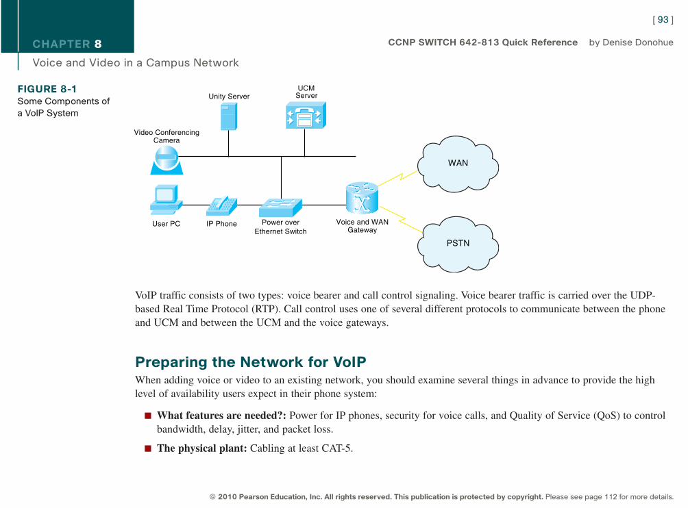
CHAPTER 8
Voice and Video in a Campus Network
VoIP traffic consists of two types: voice bearer and call control signaling. Voice bearer traffic is carried over the UDP-based Real Time Protocol (RTP). Call control uses one of several different protocols to communicate between the phoneand UCM and between the UCM and the voice gateways.
Preparing the Network for VoIPWhen adding voice or video to an existing network, you should examine several things in advance to provide the highlevel of availability users expect in their phone system:
n What features are needed?: Power for IP phones, security for voice calls, and Quality of Service (QoS) to controlbandwidth, delay, jitter, and packet loss.
n The physical plant: Cabling at least CAT-5.
[ 93 ]
© 2010 Pearson Education, Inc. All rights reserved. This publication is protected by copyright. Please see page 112 for more details.
CCNP SWITCH 642-813 Quick Reference by Denise Donohue
FIGURE 8-1Some Components of
a VoIP System
WAN
PSTN
Unity ServerUCM
Server
Power overEthernet Switch
IP PhoneUser PC Voice and WANGateway
Video ConferencingCamera
9781587140112.qxd 11/23/09 11:35 AM Page 93
CHAPTER 8
Voice and Video in a Campus Network
n Electrical power for the IP phones: Use either PoE from Catalyst switch or power inline module, or a power brick.
n Bandwidth: Commit no more than 75 percent of bandwidth. Consider all types of traffic: voice, video, and data.Have more than enough bandwidth if possible. Include both voice and call-control traffic in your planning.
n Network management: Monitor and proactively manage the network so that it is always available. Need voiceVLANs on the switches and DHCP for the phones.
n High availability: Provide redundant hardware links. Need uninterruptible power supply (UPS) with auto-restart,monitoring, and four-hour response contract. Might need generator backup. Maintain correct operating temperatures.
Network and Bandwidth Considerations
The network requirements for VoIP include:
n Maximum delay of 150–200 ms (one-way)
n No more than 1 percent packet loss
n Maximum average jitter of 30 ms
n Bandwidth of 21–106 kbps per call, plus approximately 150 bps per phone for control traffic
A formula to use when calculating bandwidth needed for voice calls is as follows:
(Packet payload + all headers) * Packet rate per second
Voice VLANs
Cisco switches can be configured to dynamically place IP telephones into a Voice, or auxiliary, VLAN separate from thedata VLANs. They can do this even when the phone and PC are physically connected to the same switch port. VoiceVLANs enable phones to be dynamically placed in a separate IP subnet from hosts, to have QoS (using 802.1Q/pheaders) and security policies applied, and make troubleshooting easier.
[ 94 ]
© 2010 Pearson Education, Inc. All rights reserved. This publication is protected by copyright. Please see page 112 for more details.
CCNP SWITCH 642-813 Quick Reference by Denise Donohue
9781587140112.qxd 11/23/09 11:35 AM Page 94

CHAPTER 8
Voice and Video in a Campus Network
Cisco IP phones have a small internal switch that places an 802.1q tag on voice traffic and marks the Class of Service(CoS) bits in the tag. Data traffic is sent untagged over the native VLAN. The switch port does not actually become atrunk and still can be configured as an access port. It is considered a multi-VLAN access port.
Power over Ethernet (PoE) Switches
IP phones can receive power from PoE switches, eliminating the need for an electrical plug.
Two power standards are the Cisco Inline PoE and the IEEE’s 802.3af standard. Both have a method for sensing that apowered device is connected to the port. 802.3af specifies a method for determining the amount of power needed by thedevice. Cisco devices, when connected to Cisco switches, can additionally use CDP to send that information. Most IPphones require no more than 15 W of power specified in 802.3af, but some new phones, access points, and surveillancecameras require more. The 802.3at standard will specify up to 30 W of power. Some Cisco switches can currently supplyup to 20 W.
Because a switch assumes 15.4 W of power until the connected device tells it the amount needed (via CDP), calculateyour power budget based on 15.4 W for all devices because if the switch reboots, all ports will ask for 15.4 W until theyget the correct information. Non-CDP devices always get allocated 15.4 W.
Cisco PoE switches automatically detect and provide power. To disable this function, or to reenable it, use the interfacecommand power inline {never | auto}. To view interfaces and the power allotted to each, use show power inline [inter-face].
QoS for VoIPQoS gives special treatment to certain traffic at the expense of others. Using QoS in the network has several advantages:
n Prioritizes access to resources so that critical traffic can be served
n Allows good management of network resources
[ 95 ]
© 2010 Pearson Education, Inc. All rights reserved. This publication is protected by copyright. Please see page 112 for more details.
CCNP SWITCH 642-813 Quick Reference by Denise Donohue
9781587140112.qxd 11/23/09 11:35 AM Page 95
CHAPTER 8
Voice and Video in a Campus Network
n Allows service to be tailored to network needs
n Allows mission-critical applications to share the network with other data
People sometimes think that there is no need for QoS strategies in a LAN. However, switch ports can experience conges-tion because of port speed mismatches, many people trying to access the switch backbone, and many people trying tosend traffic to the same switch port (such as a server port). Voice and video traffic contends with, and can be affected by,data traffic within both the WAN and the LAN.
QoS Actions
Three QoS strategies are commonly implemented on interfaces in which traffic enters the switch:
n Classification: Distinguishing one type of traffic from another. After traffic is classified, other actions can beperformed on it. Some classification methods include access lists, ingress interface, and NBAR.
n Marking: At Layer 2, placing an 802.1p CoS value within the 802.1Q frame tag. At Layer 3, setting IP Precedenceor Differentiated Services Code Point (DSCP) values in the packet’s IP header.
n Policing: Determining whether a specific type of traffic is within preset bandwidth levels. If so, it is usually allowedand might be marked. If not, the traffic is typically marked or dropped. CAR and class-based policing are examplesof policing techniques.
Other QoS techniques are typically used on outbound interfaces:
n Traffic shaping and conditioning: Attempts to send traffic out in a steady stream at a specified rate. Buffers trafficthat goes above that rate and sends it when there is less traffic on the line.
n Queuing: After traffic is classified and marked, one way it can be given special treatment is to be put into differentqueues on the interface to be sent out at different rates and times. Some examples include priority queuing, weightedfair queuing, and custom queuing. The default queuing method for a switch port is FIFO.
[ 96 ]
© 2010 Pearson Education, Inc. All rights reserved. This publication is protected by copyright. Please see page 112 for more details.
CCNP SWITCH 642-813 Quick Reference by Denise Donohue
9781587140112.qxd 11/23/09 11:35 AM Page 96
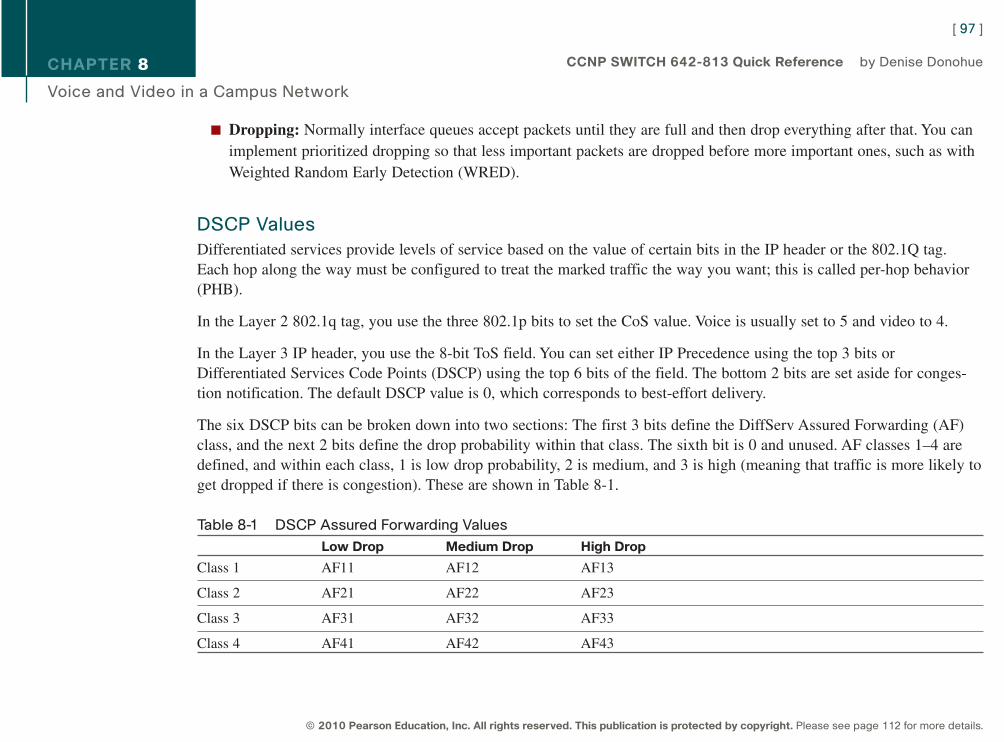
CHAPTER 8
Voice and Video in a Campus Network
n Dropping: Normally interface queues accept packets until they are full and then drop everything after that. You canimplement prioritized dropping so that less important packets are dropped before more important ones, such as withWeighted Random Early Detection (WRED).
DSCP Values
Differentiated services provide levels of service based on the value of certain bits in the IP header or the 802.1Q tag.Each hop along the way must be configured to treat the marked traffic the way you want; this is called per-hop behavior(PHB).
In the Layer 2 802.1q tag, you use the three 802.1p bits to set the CoS value. Voice is usually set to 5 and video to 4.
In the Layer 3 IP header, you use the 8-bit ToS field. You can set either IP Precedence using the top 3 bits orDifferentiated Services Code Points (DSCP) using the top 6 bits of the field. The bottom 2 bits are set aside for conges-tion notification. The default DSCP value is 0, which corresponds to best-effort delivery.
The six DSCP bits can be broken down into two sections: The first 3 bits define the DiffServ Assured Forwarding (AF)class, and the next 2 bits define the drop probability within that class. The sixth bit is 0 and unused. AF classes 1–4 aredefined, and within each class, 1 is low drop probability, 2 is medium, and 3 is high (meaning that traffic is more likely toget dropped if there is congestion). These are shown in Table 8-1.
Table 8-1 DSCP Assured Forwarding Values
Low Drop Medium Drop High Drop
Class 1 AF11 AF12 AF13
Class 2 AF21 AF22 AF23
Class 3 AF31 AF32 AF33
Class 4 AF41 AF42 AF43
[ 97 ]
© 2010 Pearson Education, Inc. All rights reserved. This publication is protected by copyright. Please see page 112 for more details.
CCNP SWITCH 642-813 Quick Reference by Denise Donohue
9781587140112.qxd 11/23/09 11:35 AM Page 97
CHAPTER 8
Voice and Video in a Campus Network
Voice bearer traffic uses an Expedited Forwarding value of DSCP 46 to give it higher priority within the network.
Trust Boundaries
When IP traffic comes in already marked, the switch has some options about how to handle it. It can:
n Trust the DSCP value in the incoming packet, if present.
n Trust the IP Precedence value in the incoming packet, if present.
n Trust the CoS value in the incoming frame, if present.
n Classify the traffic based on an IP access control list or a MAC address access control list.
Mark traffic for QoS as close to the source as possible. If the source is an IP telephone, it can mark its own traffic. If not,the building access module switch can do the marking. If those are not under your control, you might need to mark at thedistribution layer. Classifying and marking slows traffic flow, so do not do it at the core. All devices along the path shouldthen be configured to trust the marking and provide a level of service based on it. The place where trusted marking isdone is called the trust boundary.
Configuring VoIP Support on a SwitchBefore implementing VoIP, plan the following:
1. PoE: Ensure that enough power is available for all phones, with a UPS backup.
2. Voice VLAN: Determine the number of VLANs needed and the associated IP subnets. Add DHCP scopes for thephones, and add the phone networks to the routing protocol.
3. QoS: Decide which marking and queues will be used. Implement AutoQoS and then tune as needed.
[ 98 ]
© 2010 Pearson Education, Inc. All rights reserved. This publication is protected by copyright. Please see page 112 for more details.
CCNP SWITCH 642-813 Quick Reference by Denise Donohue
9781587140112.qxd 11/23/09 11:35 AM Page 98
CHAPTER 8
Voice and Video in a Campus Network
4. Fast Convergency: To enhance high availability, tune the routing and HSRP/VRRP/GLBP timers.
5. Test Plan: Test the voice implementation thoroughly before converting users to it. Check that both the phone and PCget the correct IP addresses, that the phone registers with the UCM, and that calls to and from the phone succeed.
Manual Configuration
To associate a voice VLAN with a switch port, use the following:
Switch(config-if)# switchport voice vlan vlan-ID
To configure an IOS switch to trust the markings on traffic entering an interface, use the following:
Switch(config-if)# mls qos trust {dscp | cos}
To configure the switch to trust the traffic markings only if a Cisco phone is connected, use the following:
Switch(config-if)# mls qos trust device cisco-phone
To set a COS value for frames coming from a PC attached to the phone, use the following:
Switch(config-if)# switchport priority extend cos cos-value
To verify the interface parameters, use the following:
Switch(config-if)# show interfaces interface switchport
To verify the QoS parameters on an interface, use the following:
Switch(config-if)# show mls qos interface interface
[ 99 ]
© 2010 Pearson Education, Inc. All rights reserved. This publication is protected by copyright. Please see page 112 for more details.
CCNP SWITCH 642-813 Quick Reference by Denise Donohue
9781587140112.qxd 11/23/09 11:35 AM Page 99
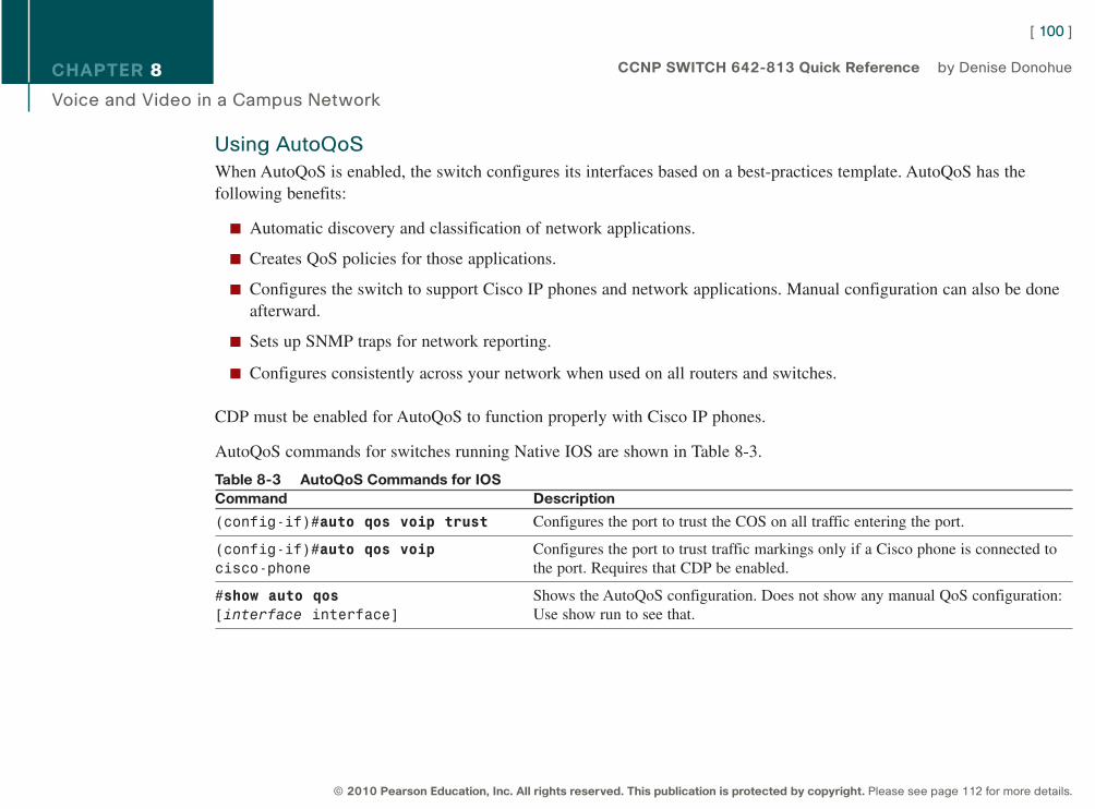
CHAPTER 8
Voice and Video in a Campus Network
Using AutoQoS
When AutoQoS is enabled, the switch configures its interfaces based on a best-practices template. AutoQoS has thefollowing benefits:
n Automatic discovery and classification of network applications.
n Creates QoS policies for those applications.
n Configures the switch to support Cisco IP phones and network applications. Manual configuration can also be doneafterward.
n Sets up SNMP traps for network reporting.
n Configures consistently across your network when used on all routers and switches.
CDP must be enabled for AutoQoS to function properly with Cisco IP phones.
AutoQoS commands for switches running Native IOS are shown in Table 8-3.
Table 8-3 AutoQoS Commands for IOSCommand Description
(config-if)#auto qos voip trust Configures the port to trust the COS on all traffic entering the port.
(config-if)#auto qos voip Configures the port to trust traffic markings only if a Cisco phone is connected to cisco-phone the port. Requires that CDP be enabled.
#show auto qos Shows the AutoQoS configuration. Does not show any manual QoS configuration:[interface interface] Use show run to see that.
[ 100 ]
© 2010 Pearson Education, Inc. All rights reserved. This publication is protected by copyright. Please see page 112 for more details.
CCNP SWITCH 642-813 Quick Reference by Denise Donohue
9781587140112.qxd 11/23/09 11:35 AM Page 100
CHAPTER 8
Voice and Video in a Campus Network
Video over IPVideo traffic roughly falls into one of three categories: many-to-many, many-to-few, and few-to-many.
Many-to-many includes interactive video, such as Telepresence, Webex, desktop video conferencing, and other peer-to-peer video and collaboration applications. The data flow is client-to-client, or MCU-to-client. Bandwidth needs for highdefinition video vary during the session but are high-up to 12 Mb/s per location, with compression.
Many-to-few sessions represent IP surveillance cameras. The video flow is from the camera source to a storage location,from storage to a client, or from the source to a client. These typically require up to 4 Mb/s of bandwidth per camera.
Few-to-many describes the typical streaming video, either from an internal company source or an Internet source. It alsoapplies to digital signage media. This is the most predictable of all video streams and users typically tolerate less-than-perfect quality. Traffic flows are from storage-to-client or from server-to-client.
QoS Requirements for VideoVideo traffic should be compressed because of its high bandwidth needs, but this causes a lot of variation in networktraffic. A picture that does not change much can compress well, resulting in fairly low bandwidth use. But when there area lot of changes in the picture, such as when someone moves or shares a new document, compression does not work aswell, which results in high bandwidth use. In contrast, voice traffic is fairly steady.
Video should be placed in its own queue and might be prioritized depending on company requirements. Consider placinginteractive and streaming video into different queues. Aim to provide no more than 200 ms of latency for most videoapplications.
Make sure that there is sufficient bandwidth in the network before adding video applications.
[ 101 ]
© 2010 Pearson Education, Inc. All rights reserved. This publication is protected by copyright. Please see page 112 for more details.
CCNP SWITCH 642-813 Quick Reference by Denise Donohue
9781587140112.qxd 11/23/09 11:35 AM Page 101
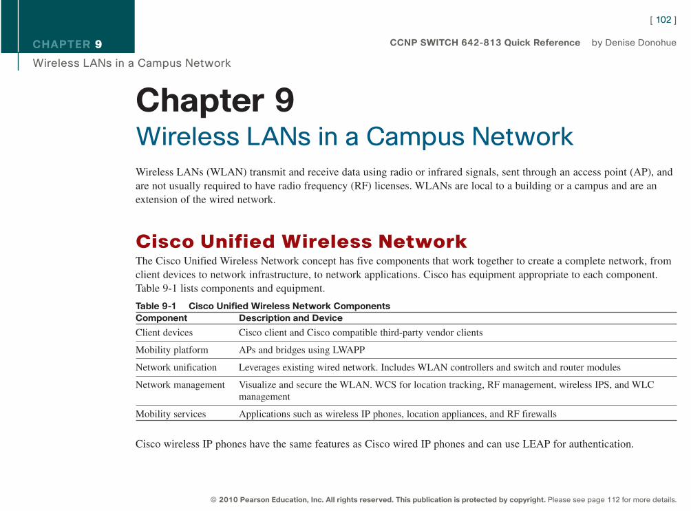
CHAPTER 9
Wireless LANs in a Campus Network
Chapter 9Wireless LANs in a Campus Network
Wireless LANs (WLAN) transmit and receive data using radio or infrared signals, sent through an access point (AP), andare not usually required to have radio frequency (RF) licenses. WLANs are local to a building or a campus and are anextension of the wired network.
Cisco Unified Wireless NetworkThe Cisco Unified Wireless Network concept has five components that work together to create a complete network, fromclient devices to network infrastructure, to network applications. Cisco has equipment appropriate to each component.Table 9-1 lists components and equipment.
Table 9-1 Cisco Unified Wireless Network ComponentsComponent Description and Device
Client devices Cisco client and Cisco compatible third-party vendor clients
Mobility platform APs and bridges using LWAPP
Network unification Leverages existing wired network. Includes WLAN controllers and switch and router modules
Network management Visualize and secure the WLAN. WCS for location tracking, RF management, wireless IPS, and WLCmanagement
Mobility services Applications such as wireless IP phones, location appliances, and RF firewalls
Cisco wireless IP phones have the same features as Cisco wired IP phones and can use LEAP for authentication.
[ 102 ]
© 2010 Pearson Education, Inc. All rights reserved. This publication is protected by copyright. Please see page 112 for more details.
CCNP SWITCH 642-813 Quick Reference by Denise Donohue
9781587140112.qxd 11/23/09 11:35 AM Page 102
CHAPTER 9
Wireless LANs in a Campus Network
The Cisco Compatible Extensions Program tests other vendors’ devices for compatibility with Cisco wireless products.Using products certified by this program ensures full functionality of Cisco enhancements and proprietary extensions.
Characteristics of Wireless LANsWLANs function similarly to Ethernet LANs with the access point providing connectivity to the rest of the network aswould a switch. The physical layer is radio waves, rather than wires. IEEE 802.11standard defines the physical and datalink specifications, including the use of MAC addresses. The same protocols (such as IP) and applications (such as IPsec)can run over both wired and wireless LANs.
The following lists some characteristics of wireless LANs and the data transmitted over wireless networks.
n WLANs use Carrier Sense Multi-Access/Collision Avoidance (CSMA/CA).
n Wireless data is half-duplex. CSMA/CA uses Request to Send (RTS) and Clear to Send (CTS) messages to avoidcollisions.
n Radio waves have unique potential issues. They are susceptible to interference, multipath distortion, and noise. Theircoverage area can be blocked by building features, such as elevators. The signal might reach outside the building andlead to privacy issues.
n WLAN hosts have no physical network connection. They are often mobile and often battery-powered. The wirelessnetwork design must accommodate this.
n WLANs must adhere to each country’s RF standards.
[ 103 ]
© 2010 Pearson Education, Inc. All rights reserved. This publication is protected by copyright. Please see page 112 for more details.
CCNP SWITCH 642-813 Quick Reference by Denise Donohue
9781587140112.qxd 11/23/09 11:35 AM Page 103
CHAPTER 9
Wireless LANs in a Campus Network
Service Set Identifiers (SSID)An SSID maps to a VLAN and can be used to segment users into groups requiring different security or QoS treatment.SSIDs can be broadcast by the access point or statically configured on the client, but the client must have the same SSIDas the AP to register with it. SSID names are case sensitive. When multiple SSIDs/VLANs are used on an AP, the wiredconnection back to the network must be a trunk to carry all the VLANs.
WLAN TopologiesThe use of wireless products falls into three categories:
n Client access, which allows mobile users to access the wired LAN resources
n Wireless connections between buildings
n Wireless mesh
Wireless connections can be made in ad-hoc mode or infrastructure mode. Ad-hoc mode (or Independent Basic ServiceSet [IBSS]) is simply a group of computers talking wirelessly to each other with no access point (AP). It is limited inrange and functionality. Infrastructure mode’s BSS uses one AP to connect clients. The range of the AP’s signal, called itsmicrocell, must encompass all clients. The Extended Service Set (ESS) uses multiple APs with overlapping microcells tocover all clients. Microcells should overlap by 10–15 percent for data and 15–20 percent for voice traffic. Each AP shoulduse a different channel. “Pico” cells, with even smaller coverage areas, can also be used.
Workgroup bridges connect to devices without a wireless network interface card (NIC) to allow their access to the wire-less network.
Wireless mesh networks can span large distances because only the edge APs connect to the wired network. The interme-diate APs connect wirelessly to multiple other APs and act as repeaters for them. Each AP has multiple paths through thewireless network. The Adaptive Wireless Path (AWP) protocol runs between APs to determine the best path to the wirednetwork. APs choose backup paths if the best path fails.
[ 104 ]
© 2010 Pearson Education, Inc. All rights reserved. This publication is protected by copyright. Please see page 112 for more details.
CCNP SWITCH 642-813 Quick Reference by Denise Donohue
9781587140112.qxd 11/23/09 11:35 AM Page 104
CHAPTER 9
Wireless LANs in a Campus Network
Client ConnectivityClients associate with an access point as follows:
Access points send out beacons announcing information such as SSID, unless configured not to.
Step 1. The client sends a probe request and listens for beacons and probe responses.
Step 2. The AP sends a probe response.
Step 3. The client initiates an association to the AP. 802.1x authentication, and any other security information is sentto the AP.
Step 4. The AP accepts the association. SSID and MAC address information is exchanged.
Step 5. The AP adds the client’s MAC address to its association table.
Clients can roam between APs, but the APs must be configured with the same SSIDs/VLANs and security settings. Layer2 roaming is done between APs on the same subnet and managed by the switches using a multicast protocol: Inter-AccessPoint Protocol (IAPP). Layer 3 roaming is done between APs on different subnets and is managed by the wireless LANcontrollers. The switch connected to the AP updates its MAC address table when a client roams.
Short roaming times are needed for VoIP to reduce delay. A client will attempt to roam (or associate with another AP)when
n It misses too many beacons from the AP.
n The data rate is reduced.
n The maximum data retry count is exceeded.
n It is configured to search for another AP at regular intervals.
[ 105 ]
© 2010 Pearson Education, Inc. All rights reserved. This publication is protected by copyright. Please see page 112 for more details.
CCNP SWITCH 642-813 Quick Reference by Denise Donohue
9781587140112.qxd 11/23/09 11:35 AM Page 105
CHAPTER 9
Wireless LANs in a Campus Network
Cisco Wireless Network ComponentsCisco supports two types of wireless solutions: one using autonomous access points, and one using lightweight (or“dumb”) access points in combination with WLAN controllers. The wired network infrastructure is the same for bothtypes: switches and routers.
Access points can receive their power from Power over Ethernet (PoE) switches, routers with PoE switch modules, ormidspan power injectors, thus alleviating the need for electrical outlets near them. APs require up to 15 W of power, soplan your power budget accordingly.
Autonomous (Stand-alone) APsAutonomous APs run Cisco IOS, are programmed individually, and act independently. They can be centrally managedwith the CiscoWorks Wireless LAN Solution Engine (WLSE), can use Cisco Secure Access Control Server (ACS) forRADIUS and TACAS+ authentication, and Wireless Domain Services (WDS) for RF management. Redundancy consistsof multiple APs.
Network Design for Autonomous APs
When using stand-alone APs, the traffic flow is from client to AP to connected switch, and from there into the rest of thenetwork. Plan the SSIDs and VLANs that will be on each AP, keeping in mind any roaming that users might do.Autonomous APs support Layer 2 roaming only, so SSIDs and VLAN must be statically configured on every AP in whicha user might roam. Make sure to include a management VLAN on the AP.
Ensure that the AP has a power source, either a PoE switch or a power injector. Configure the switch interface connectedto the AP as a trunk if the AP has multiple VLANs.
[ 106 ]
© 2010 Pearson Education, Inc. All rights reserved. This publication is protected by copyright. Please see page 112 for more details.
CCNP SWITCH 642-813 Quick Reference by Denise Donohue
9781587140112.qxd 11/23/09 11:35 AM Page 106
CHAPTER 9
Wireless LANs in a Campus Network
Lightweight Access PointsLightweight APs divide the 802.11 processing between the AP and a Cisco Wireless LAN Controller (WLC). This issometimes called “split MAC,” because they split the functions of the MAC layer, Layer 2. Their management compo-nents also include the Wireless Control System (WCS) and a location-tracking appliance. Redundancy consists of multi-ple WLCs. The AP handles real-time processes, and the WLC handles processes such as:
n Authentication
n Client association/mobility management
n Security management
n QoS policies
n VLAN tagging
n Forwarding of user traffic
The Lightweight Access Point Protocol (LWAPP) supports the split MAC function in traffic between a lightweight APand its controller. LWAPP uses AES-encrypted control messages and encapsulates, but does not encrypt, data traffic.
Controllers and APs can also use a new IETF-standard protocol to communicate with each other: the Control andProvisioning of Wireless Access Points (CAPWAP) protocol. CAPWAP operates very much like LWAPP.
Both LWAPP and CAPWAP operate over UDP. The controller does not have to be in the same broadcast domain and IPsubnet, just IP reachable. Lightweight APs follows this process to discover their controller:
Step 1. The AP requests a DHCP address. The DHCP response includes the management IP address of one or moreWLCs.
Step 2. The AP sends an LWAPP or CAPWAP Discovery Request message to each WLC.
[ 107 ]
© 2010 Pearson Education, Inc. All rights reserved. This publication is protected by copyright. Please see page 112 for more details.
CCNP SWITCH 642-813 Quick Reference by Denise Donohue
9781587140112.qxd 11/23/09 11:35 AM Page 107

CHAPTER 9
Wireless LANs in a Campus Network
Step 3. The WLCs respond with an LWAPP or CAPWAP Discovery Response that includes the number of APscurrently associated to it.
Step 4. The AP sends a Join Request to the WLC with the fewest APs associated to it.
Step 5. The WLC responds with a Join Response message; the AP and the controller mutually authenticate eachother and derive encryption keys to be used with future control messages. The WLC then configures the APwith settings, such as SSIDs, channels, security settings, and 802.11 parameters.
Network Design for Lightweight APs
When using lightweight APs the traffic flow is from the AP, through the network, to the controller, and from there out tothe rest of the network. User traffic is tunneled between the AP and the controller. Make sure that the AP and controllerhave Layer 3 connectivity.
The controller placement can be distributed, with a controller in each building or at each site, if no roaming betweenbuildings is needed. A centralized design, with redundant controllers placed together, such as in a data center, simplifiesmanagement and increases user mobility.
SSIDs and VLANs must be planned, just as with an autonomous AP. But the configuration is done on the controller.Clients are placed into VLANs based either on the controller they connect to or an authentication process. The manage-ment VLAN is mapped to the controller. Controllers support both Layer 2 and Layer 3 roaming.
The link between a lightweight AP and the switch is an access port, assigned to a VLAN. The link between the controllerand its connected switch is a trunk link. Controllers with several switch links can create an Etherchannel to the switch toincrease bandwidth. Link aggregation is recommended for the 4400 series and is required on the WiSM and the 3750Gintegrated controllers.
Ensure that the AP has a power source, either a PoE switch or a power injector.
[ 108 ]
© 2010 Pearson Education, Inc. All rights reserved. This publication is protected by copyright. Please see page 112 for more details.
CCNP SWITCH 642-813 Quick Reference by Denise Donohue
9781587140112.qxd 11/23/09 11:35 AM Page 108
CHAPTER 9
Wireless LANs in a Campus Network
Wireless LAN ControllersCisco WLAN controllers can be either an appliance, a module, or integrated into a 3750G switch. In the appliance line,the 5500 series is meant for large deployments and, as of this writing, supports up to 250 APs. The 4400 series is formedium-sized deployments and supports from 12 APs to 100 APs. The 2100 series is for small deployments and supportsfrom 6 APs to 25 APs.
The WLAN controller integrated into a Cisco 3750G switch can support up to 25 APs per switch,or 100 per switch stack.The Wireless Services Module (WiSM) can be installed into Cisco 6500 and 7600 series switches for large deploymentsthat need support for up to 300 APs. Cisco ISR routers have a WLAN controller module that can support up to 25 APs forsmall deployments.
Hybrid Remote Edge Access Point (H-REAP)Wireless controllers need not be in the same physical location as their associated APs. However, having an AP and itscontroller separated by a WAN link can lead to some inefficiencies and problems. Two clients in the remote location thatneed to connect would have their traffic tunneled over the WAN to the controller and back again. Additionally, the APwould lose functionality if the WAN were down.
H-REAP addresses these problems:
n Connected mode: When the controller is reachable, the AP transmits user authentication to the controller. It sendstraffic in specified WLANs (usually local traffic) to its local switch, however, rather than tunneling it back to thecontroller. The connection from the AP to switch needs to be a trunk link if the AP handles multiple VLANs. Trafficbound to remote networks is still tunneled over the WAN to the controller.
n Disconnected mode: When the controller is not reachable, the AP authenticates clients itself. It still sends client toits connected switch, but of course remote locations will not be reachable if the WAN is down.
H-REAP is configured at the controller for any APs that operate in this mode.
[ 109 ]
© 2010 Pearson Education, Inc. All rights reserved. This publication is protected by copyright. Please see page 112 for more details.
CCNP SWITCH 642-813 Quick Reference by Denise Donohue
9781587140112.qxd 11/23/09 11:35 AM Page 109
CHAPTER 9
Wireless LANs in a Campus Network
Integrating Wireless into the LANThis section covers configuring your switches for wireless APs and controllers, and planning your installation.
Switch ConfigurationWhen the switch port connects to a stand-alone AP, configure it as an access port if the AP has only one VLAN and atrunk port if it has multiple VLANs. Trust CoS if the link is a trunk. Set the trunk native VLAN to the AP’s managementVLAN. Prioritize voice if you use wireless phones.
When the switch port connects to a controller-based AP, the port should be an access port. The port should be placed intothe management VLAN because it is used for traffic between the AP and the controller. Trust DSCP on the port. If usingwireless IPT, also set up QoS to prioritize voice.
The switch port connecting to a WLAN controller should be configured as a trunk link. Limit the trunk to wireless andmanagement VLANs. Trust CoS and prioritize voice if you use wireless IP phones.
Links to a 4400 series controller might be aggregated into a Layer 2 Etherchannel. The 4400 cannot negotiate aggrega-tion, so it is important to set the channel-group mode to “On”. Otherwise, the configuration is the same as with any otherEtherchannel. Configure the channel as a trunk, allow only the management and wireless VLANs, and trust CoS.
The WiSM requires a separate VLAN for its management. This VLAN should be assigned only to the module’s serviceport and should not be used outside of the switch. Assign the VLAN to the service port with the global command wismservice-vlan vlan. Assign an IP address to the VLAN interface; this IP address is used to communicate with the WiSM.The WiSM contains eight logical ports that connect to the switch fabric in two Etherchannel bundles. It also contains twoseparate controllers. Bundle configuration is done at each controller, using the wism module slot# controller controller#set of global commands.
[ 110 ]
© 2010 Pearson Education, Inc. All rights reserved. This publication is protected by copyright. Please see page 112 for more details.
CCNP SWITCH 642-813 Quick Reference by Denise Donohue
9781587140112.qxd 11/23/09 11:35 AM Page 110

CHAPTER 9
Wireless LANs in a Campus Network
Planning for a Wireless ImplementationIn planning a wireless implementation, first gather requirements. Some questions to ask include the following:
n How many APs and where will they be installed?
n Stand-alone or controller-based?
n If controller-based, where will the controllers be located?
n Is PoE available?
n What VLANs and SSIDs will be used?
n What are the bandwidth requirements?
n What are the QoS requirements?
n Do you need security such as ACLs or Radius server?
n Do you need UPS for controllers?
When the requirements are gathered, create an implementation plan with details such as:
n Total needs, from the requirements that were previously gathered
n Any changes needed to the network design
n Any additional equipment needed
n Implementation steps
n Testing plan
The test plan might include checking that the AP and its clients get a DHCP address, that the AP is reachable from amanagement station, that clients can reach the network and Internet, and that the controller can reach the Radius server ifused. To troubleshoot problems with wireless connectivity, review the steps for an AP to register with a WLC and a clientwith an AP.
[ 111 ]
© 2010 Pearson Education, Inc. All rights reserved. This publication is protected by copyright. Please see page 112 for more details.
CCNP SWITCH 642-813 Quick Reference by Denise Donohue
9781587140112.qxd 11/23/09 11:35 AM Page 111
CCNP SWITCH Quick Reference Denise Donohue Copyright © 2010 Pearson Education, Inc.
Published by:Cisco Press800 East 96th StreetIndianapolis, Indiana 46240 USA
All rights reserved. No part of this ebook may be reproduced or transmitted in anyform or by any means, electronic or mechanical, including photocopying, recording, orby any information storage and retrieval system, without written permission from thepublisher, except for the inclusion of brief quotations in a review.
First Digital Edition January 2010
ISBN-10: 1-58714-011-X
ISBN-13: 0 978-1-58714-011-2
Warning and DisclaimerThis ebook is designed to provide information about networking. Every effort has beenmade to make this ebook as complete and accurate as possible, but no warranty orfitness is implied.
The information is provided on an “as is” basis. The authors, Cisco Press, and CiscoSystems, Inc. shall have neither liability nor responsibility to any person or entity withrespect to any loss or damages arising from the information contained in this ebook.
The opinions expressed in this ebook belong to the authors and are not necessarilythose of Cisco Systems, Inc.
Trademark AcknowledgmentsAll terms mentioned in this ebook that are known to be trademarks or service markshave been appropriately capitalized. Cisco Press or Cisco Systems, Inc. cannot attest tothe accuracy of this information. Use of a term in this ebook should not be regarded asaffecting the validity of any trademark or service mark.
Feedback InformationAt Cisco Press, our goal is to create in-depth technical books of the highest quality and value. Each book is craftedwith care and precision, undergoing rigorous development that involves the unique expertise of members of theprofessional technical community.
Reader feedback is a natural continuation of this process. If you have any comments on how we could improve thequality of this ebook, or otherwise alter it to better suit your needs, you can contact us through e-mail [email protected]. Please be sure to include the ebook title and ISBN in your message.
We greatly appreciate your assistance.
Corporate and Government SalesThe publisher offers excellent discounts on this ebook when ordered in quantity for bulk purchases or special sales,which may include electronic versions and/or custom covers and content particular to your business, training goals,marketing focus, and branding interests. For more information, please contact: U.S. Corporate and GovernmentSales 1-800-382-3419 [email protected].
For sales outside the United States please contact: International Sales [email protected]
Cisco has more than 200 offices worldwide. Addresses, phone numbers, and fax numbers are listed on the Cisco Website at www.cisco.com/go/offices.
CCDE, CCENT, Cisco Eos, Cisco HealthPresence, the Cisco logo, Cisco Lumin, Cisco Nexus, Cisco StadiumVision, Cisco TelePresence, Cisco WebEx, DCE, and Welcome to the Human Network are trademarks; Changing the Way We Work, Live, Play, and Learn and Cisco Store are service marks; and Access Registrar, Aironet, AsyncOS, Bringing the Meeting To You, Catalyst, CCDA, CCDP, CCIE, CCIP, CCNA, CCNP, CCSP, CCVP, Cisco, the Cisco Certified Internetwork Expert logo, Cisco IOS, Cisco Press, Cisco Systems, Cisco Systems Capital, the Cisco Systems logo, Cisco Unity, Collaboration Without Limitation, EtherFast, EtherSwitch, Event Center, Fast Step, Follow Me Browsing, FormShare, GigaDrive, HomeLink, Internet Quotient, IOS, iPhone, iQuick Study, IronPort, the IronPort logo, LightStream, Linksys, MediaTone, MeetingPlace, MeetingPlace Chime Sound, MGX, Networkers, Networking Academy, Network Registrar, PCNow, PIX, PowerPanels, ProConnect, ScriptShare, SenderBase, SMARTnet, Spectrum Expert, StackWise, The Fastest Way to Increase Your Internet Quotient, TransPath, WebEx, and the WebEx logo are registered trademarks of Cisco Systems, Inc. and/or its affiliates in the United States and certain other countries.
All other trademarks mentioned in this document or website are the property of their respective owners. The use of the word partner does not imply a partnership relationship between Cisco and any other company. (0812R)
Americas HeadquartersCisco Systems, Inc.San Jose, CA
Asia Pacific HeadquartersCisco Systems (USA) Pte. Ltd.Singapore
Europe HeadquartersCisco Systems International BVAmsterdam, The Netherlands
© 2010 Pearson Education, Inc. All rights reserved. This publication is protected by copyright.
9781587140112.qxd 11/23/09 11:35 AM Page 112