CCNP ROUTE 642-902 - pearsoncmg.com
100
Transcript of CCNP ROUTE 642-902 - pearsoncmg.com


Cisco Press
800 East 96th Street
Indianapolis, IN 46240
CCNP ROUTE 642-902Official Certification Guide
Wendell Odom, CCIE No. 1624

CCNP ROUTE 642-902 Official Certification Guide
Wendell Odom
Copyright© 2010 Pearson Education, Inc.
Published by:Cisco Press800 East 96th Street Indianapolis, IN 46240 USA
All rights reserved. No part of this book may be reproduced or transmitted in any form or by any means,electronic or mechanical, including photocopying, recording, or by any information storage and retrievalsystem, without written permission from the publisher, except for the inclusion of brief quotations in areview.
Printed in the United States of America
Fifth Printing: January 2012
Odom, Wendell.CCNP Route 642-902 official certification guide / Wendell Odom.
p. cm.ISBN 978-1-58720-253-7 (hardback w/cd)
1. Routers (Computer networks)--Examinations--Study guides. 2.Routing protocols (Computer network protocols)--Examinations--Studyguides. 3. Internetworking (Telecommunication)--Examinations--Studyguides. 4. Telecommunicationsengineers--Certification--Examinations--Study guides. I. Title.
TK5105.543.O36 2010004.6'2--dc22
2009049908
ISBN-13: 978-1-58720-253-7
ISBN-10: 1-58720-253-0
Warning and Disclaimer
This book is designed to provide information about the Cisco ROUTE exam (642-902). Every effort hasbeen made to make this book as complete and as accurate as possible, but no warranty or fitness is implied.
The information is provided on an “as is” basis. The authors, Cisco Press, and Cisco Systems, Inc. shall haveneither liability nor responsibility to any person or entity with respect to any loss or damages arising fromthe information contained in this book or from the use of the discs or programs that may accompany it.
The opinions expressed in this book belong to the author and are not necessarily those of Cisco Systems, Inc.
ii CCNP ROUTE 642-902 Official Certification Guide

Trademark Acknowledgments
All terms mentioned in this book that are known to be trademarks or service marks have been appropriate-ly capitalized. Cisco Press or Cisco Systems, Inc., cannot attest to the accuracy of this information. Use ofa term in this book should not be regarded as affecting the validity of any trademark or service mark.
Corporate and Government Sales
The publisher offers excellent discounts on this book when ordered in quantity for bulk purchases or spe-cial sales, which may include electronic versions and/or custom covers and content particular to your busi-ness, training goals, marketing focus, and branding interests. For more information, please contact: U.S.Corporate and Government Sales 1-800-382-3419 [email protected]
For sales outside the United States please contact: International Sales [email protected]
Feedback Information
At Cisco Press, our goal is to create in-depth technical books of the highest quality and value. Each bookis crafted with care and precision, undergoing rigorous development that involves the unique expertise ofmembers from the professional technical community.
Readers’ feedback is a natural continuation of this process. If you have any comments regarding how wecould improve the quality of this book, or otherwise alter it to better suit your needs, you can contact usthrough email at [email protected]. Please make sure to include the book title and ISBN in yourmessage.
We greatly appreciate your assistance.
Publisher: Paul Boger Business Operation Manager, Cisco Press: Anand Sundaram
Associate Publisher: Dave Dusthimer Manager Global Certification: Erik Ullanderson
Executive Editor: Brett Bartow Technical Editors: Michelle Plumb, Jerold Swan, Rick Graziani
Managing Editor: Patrick Kanouse Copy Editor: Apostrophe Editing Services
Development Editor: Dayna Isley Proofreader: Barbara Hacha
Project Editor: Mandie Frank Editorial Assistant: Vanessa Evans
Book Designer: Louisa Adair
Composition: Mark Shirar
Indexer: Ken Johnson
iii

About the Author
Wendell Odom, CCIE No. 1624, has been in the networking industry since 1981. He hasworked as a network engineer, consultant, systems engineer, instructor, and course devel-oper; he currently works writing and creating certification tools. He is author of all theprevious editions of the CCNA Exam Certification Guide series from Cisco Press, aswell as the CCNP ROUTE 642-902 Official Certification Guide, the CCIE Routing
and Switching Official Exam Certification Guide, Computer Networking First Step,the CCNA Video Mentor, and he is the primary networking consultant for the CCNA
640-802 Network Simulator. He maintains lists of Cisco certification tools, suggestions,and links to his Cisco certification blog at www.certskills.com.
About the Technical Reviewers
Michelle Plumb is a full-time Cisco certified instructor for Skillsoft. Michelle has morethan 19 years experience in the field as an IT professional and telephony specialist. Shemaintains a high level of Cisco and Microsoft certifications. Michelle has been a techni-cal reviewer for numerous books related to the Cisco CCNP and CCVP course materialtrack. Michelle currently lives in Scottsdale, Arizona, with her husband and two dogs.
Jerold Swan, CCIE No. 17783, CCSP, works as a senior network engineer for theSouthern Ute Indian Tribe Growth Fund in southwest Colorado. Prior to that he was aCisco instructor for Global Knowledge. He has also worked in IT in the service providerand higher education sectors. His areas of interest include routing protocols, security, andnetwork monitoring. He is a graduate of Stanford University. His other interests includetrail running, mountain biking, and volunteer search and rescue.
Rick Graziani teaches computer science and computer networking courses at CabrilloCollege in Aptos, California. Rick has worked and taught in the computer networking andinformation technology field for almost 30 years. Prior to teaching Rick worked in IT forvarious companies including Santa Cruz Operation, Tandem Computers, and LockheedMissiles and Space Corporation. He holds an M.A. degree in computer science and sys-tems theory from California State University Monterey Bay. Rick also does consultingwork for Cisco and other companies. When Rick is not working he is most likely surfing.Rick is an avid surfer who enjoys surfing at his favorite Santa Cruz breaks.
iv CCNP ROUTE 642-902 Official Certification Guide

Dedications
For Jeffrey Lanier Odom. My favorite brother. Gentle soul. Lover of stupid jokes (“babybigger,” “tankety-tankety-tank,” “supplies”…) Nice guy. Good friend. Miss you, bro.10/7/1959—6/15/2009.
Acknowledgments
As usual, Brett Bartow, executive editor, deserves thanks for allowing me to be involvedwith this book. Brett continually keeps an eye on the horizon for the right projects forme, essentially completing a run of books from the basics, to CCENT, CCNA, nowCCNP, and CCIE. My work life wouldn’t be possible without Brett keeping me pointed inthe right direction. Thanks, Brett!
Jay Swan and Michelle Plumb did a nice job for us with technical edits of the book. Jaywas particularly helpful with both ends of the tech edit spectrum, noticing specific andeasy-to-overlook errors, while keeping an eye out for the big picture of how the text inone section impacted other sections. Michelle’s diligent work helped us uncover severalspecific issues and make this a better book. Thanks to you both for helping make thisbook much better!
Rick Graziani deserves thanks with this book for several reasons. First, Rick wrote the ques-tions on the CD with this book, a task that can be laborious—but Rick did a great job andwith a positive outlook. Additionally, Rick gave us an additional set of experienced andthoughtful technical editor eyes on the BGP chapters. And while he was working on the CDquestions, Rick gladly went the extra mile to point out technical edits to the other bookchapters as well. Rick’s great attitude toward helping with the book was very impressive.
Dayna Isley worked as the development editor for this book. Dayna and I have worked verywell together for a long time, and having such a trusted editor look over every word on thisnew book has helped quite a bit. Dayna’s attention to detail helps keep me on the authoringstraight-and-narrow, this time while navigating a sometimes fluid set of processes. Dayna,thanks for sifting through this process and making me look good on paper!
Patrick Kanouse, managing editor, led us through many new production tools(WriteRAP) and processes. Additionally, Patrick happily agreed to continue several addi-tional production tasks at my request (translated: more work for him and his team), whileallowing me to manage the entire illustration process for the first time on one of mybooks—none of which he had to do. Patrick, thanks for your great attitude and willing-ness to work with me on so many extras.
The folks on Patrick’s production team probably had the biggest challenge with this bookcompared to my other books. Mandie Frank worked as project editor, guiding the bookthrough the various back-end processes to complete the book. Mandie got to sift thoughall the changing processes, help figure out when we were doing which tasks, and keep usall on track. Thanks, Mandie! San Dee Phillips retired last year so she could work evenmore, coming back to do the copyedit work—thanks for jumping in again, San Dee! Andfor Mark Shirar, Ken Johnson, and Barbara Hacha, doing the composition, indexing, andproofreading, thanks so much for handling these details—I do see the difference with
v

having professionals working on every step of the book creation process, and I do appre-ciate the results.
Thanks to Rich Bennett, good friend and part-time do-everything guy for my books andother projects. Thanks for doing all the Illustrator drawings and editing them all so manytimes!
The old expression “my better half” is lived out every day here at the Odom house in theperson of my wife Kris. Many thanks to Kris, who listens when I need to talk throughsomething in the book, and lets me go hide in the basement for a few weeks to meet thelatest writing deadline. Thanks, doll!
Finally and foremost, many thanks to Jesus Christ, for demonstrating your love, and forhelping me and my family learn better each day how to not be a clanging symbol, butinstead to show others your love.
vi CCNP ROUTE 642-902 Official Certification Guide

Contents at a Glance
Foreword xxiv
Introduction xxv
Part I Perspectives on Network Planning
Chapter 1 Planning Tasks for the CCNP Exams 3
Part II EIGRP
Chapter 2 EIGRP Overview and Neighbor Relationships 19
Chapter 3 EIGRP Topology, Routes, and Convergence 57
Chapter 4 EIGRP Route Summarization and Filtering 97
Part III OSPF
Chapter 5 OSPF Overview and Neighbor Relationships 137
Chapter 6 OSPF Topology, Routes, and Convergence 175
Chapter 7 OSPF Route Summarization, Filtering, and Default Routing 221
Chapter 8 OSPF Virtual Links and Frame Relay Operations 257
Part IV Path Control
Chapter 9 Basic IGP Redistribution 289
Chapter 10 Advanced IGP Redistribution 329
Chapter 11 Policy-Based Routing and IP Service Level Agreement 363
Part V BGP
Chapter 12 Internet Connectivity and BGP 387
Chapter 13 External BGP 419
Chapter 14 Internal BGP and BGP Route Filtering 455
Chapter 15 BGP Path Control 491
vii

Part VI IPv6
Chapter 16 IP Version 6 Addressing 529
Chapter 17 IPv6 Routing Protocols and Redistribution 569
Chapter 18 IPv4 and IPv6 Coexistence 607
Part VII Branch Office Networking
Chapter 19 Routing over Branch Internet Connections 647
Part VIII Final Preparation
Chapter 20 Final Preparation 673
Part IX Appendixes
Appendix A Answers to “Do I Know This Already?” Quizzes 681
Appendix B Conversion Tables 701
Appendix C Route Exam Updates 705
Index 708
CD-Only Appendixes and Glossary
Appendix D Memory Tables
Appendix E Memory Tables Answer Key
Appendix F Completed Planning Practice Tables
Glossary
viii CCNP ROUTE 642-902 Official Certification Guide

Contents
Foreword xxiv
Introduction xxv
Part I Perspectives on Network Planning
Chapter 1 Planning Tasks for the CCNP Exams 3
Perspectives on CCNP Exam Topics Related to Planning 3
CCNP Route Exam Topics That Do Not Require the CLI 4
Impressions on the Planning Exam Topics 5
Relating the Exam Topics to a Typical Network Engineer’s Job 6
A Fictitious Company and Networking Staff 6
The Design Step 7
Implementation Planning Step 7
Verification Planning Step 9
Documenting the Results of the Implementation 10
Summary of the Role of Network Engineer 10
How to Prepare for the Planning Topics on the Exams 10
Planning Preparation: Design Review Table 12
Planning Preparation: Implementation Plan Peer Review Table 12
Create an Implementation Plan Table 13
Choose Commands for a Verification Plan Table 13
Background Information on Implementation and Verification Plans 13
No Single Plan Style 13
Typical Elements in an Implementation Plan 14
Focus for Implementation Plans for CCNP 15
Structured Implementation Planning Methodologies 15
Typical Verification Plan Components 16
Conclusions 16
Part II EIGRP
Chapter 2 EIGRP Overview and Neighbor Relationships 19
“Do I Know This Already?” Quiz 20
Foundation Topics 23
EIGRP CCNA Review 23
Configuration Review 23
Verification Review 25
Internals Review 29
ix

EIGRP Neighborships 32
Manipulating EIGRP Hello and Hold Timers 32
Preventing Unwanted Neighbors Using Passive Interfaces 36
Controlling Neighborships Using EIGRP Authentication 39
Controlling Neighborships with Static Configuration 43
Configuration Settings That Could Prevent Neighbor Relationships 46
Neighborship over WANs 48
Neighborship on Frame Relay 49
Neighborship on MPLS VPN 50
Neighborship on Metro Ethernet 51
Exam Preparation Tasks 52
Planning Practice 52
Design Review Table 52
Implementation Plan Peer Review Table 52
Create an Implementation Plan Table 53
Choose Commands for a Verification Plan Table 53
Review All the Key Topics 55
Complete the Tables and Lists from Memory 55
Define Key Terms 55
Chapter 3 EIGRP Topology, Routes, and Convergence 57
“Do I Know This Already?” Quiz 57
Foundation Topics 60
Building the EIGRP Topology Table 60
Seeding the EIGRP Topology Table 60
The Content of EIGRP Update Message 61
The EIGRP Update Process 64
WAN Issues for EIGRP Topology Exchange 65
Building the IP Routing Table 69
Calculating the Metrics: Feasible Distance and Reported Distance 69
EIGRP Metric Tuning 72
Optimizing EIGRP Convergence 78
Fast Convergence to Feasible Successors 78
Converging by Going Active 83
Unequal Metric Route Load Sharing 88
Exam Preparation Tasks 92
Planning Practice 92
Design Review Table 92
x CCNP ROUTE 642-902 Official Certification Guide

Implementation Plan Peer Review Table 92
Create an Implementation Plan Table 93
Choose Commands for a Verification Plan Table 94
Review all the Key Topics 94
Complete the Tables and Lists from Memory 95
Define Key Terms 95
Chapter 4 EIGRP Route Summarization and Filtering 97
“Do I Know This Already?” Quiz 97
Foundation Topics 101
Route Filtering 101
Filtering by Referencing ACLs 102
Filtering by Referencing IP Prefix Lists 105
Filtering by Using Route Maps 110
Route Summarization 114
Route Summarization Design 114
Configuring EIGRP Route Summarization 120
Auto-summary 124
Default Routes 126
Default Routing to the Internet Router 126
Default Routing Configuration with EIGRP 127
Exam Preparation Tasks 132
Planning Practice 132
Design Review Table 132
Implementation Plan Peer Review Table 132
Create an Implementation Plan Table 133
Choose Commands for a Verification Plan Table 134
Review all the Key Topics 134
Complete the Tables and Lists from Memory 135
Define Key Terms 135
Part III OSPF
Chapter 5 OSPF Overview and Neighbor Relationships 137
“Do I Know This Already?” Quiz 137
Foundation Topics 140
OSPF Review 140
OSPF Link State Concepts 140
OSPF Configuration Review 144
xi

OSPF Verification Review 146
OSPF Feature Summary 149
OSPF Neighbors and Adjacencies on LANs 149
Enabling OSPF Neighbor Discovery on LANs 150
Settings That Must Match for OSPF Neighborship 152
OSPF Neighbors and Adjacencies on WANs 162
OSPF Network Types 162
OSPF Neighborship over Point-to-Point Links 163
Neighborship over Frame Relay Point-to-Point Subinterfaces 166
Neighborship on MPLS VPN 166
Neighborship on Metro Ethernet 167
Exam Preparation Tasks 170
Planning Practice 170
Design Review Table 170
Implementation Plan Peer Review Table 170
Create an Implementation Plan Table 171
Choose Commands for a Verification Plan Table 172
Review All the Key Topics 173
Complete the Tables and Lists from Memory 173
Define Key Terms 173
Chapter 6 OSPF Topology, Routes, and Convergence 175
“Do I Know This Already?” Quiz 175
Foundation Topics 179
LSAs and the OSPF Link State Database 179
LSA Type 1: Router LSA 180
LSA Type 2: Network LSA 186
LSA Type 3: Summary LSA 191
Limiting the Number of LSAs 195
Summary of Internal LSA Types 195
The Database Exchange Process 196
OSPF Message and Neighbor State Reference 196
Exchange Without a Designated Router 197
Exchange with a Designated Router 200
Flooding Throughout the Area 203
Periodic Flooding 204
Choosing the Best OSPF Routes 204
OSPF Metric Calculation for Internal OSPF Routes 205
xii CCNP ROUTE 642-902 Official Certification Guide

Metric and SPF Calculations 211
Metric Tuning 212
Exam Preparation Tasks 215
Planning Practice 215
Design Review Table 215
Implementation Plan Peer Review Table 215
Create an Implementation Plan Table 216
Choose Commands for a Verification Plan Table 216
Review All the Key Topics 218
Complete the Tables and Lists from Memory 218
Define Key Terms 218
Chapter 7 OSPF Route Summarization, Filtering, and Default Routing 221
“Do I Know This Already?” Quiz 221
Foundation Topics 225
Route Filtering 225
Type 3 LSA Filtering 226
Filtering OSPF Routes Added to the Routing Table 230
Route Summarization 231
Manual Summarization at ABRs 232
Manual Summarization at ASBRs 235
Default Routes and Stub Areas 236
Domain-wide Defaults Using the default-information originate Command 237
Stubby Areas 239
Exam Preparation Tasks 251
Planning Practice 251
Design Review Table 251
Implementation Plan Peer Review Table 251
Create an Implementation Plan Table 252
Choose Commands for a Verification Plan Table 253
Review All the Key Topics 253
Complete the Tables and Lists from Memory 254
Define Key Terms 254
Chapter 8 OSPF Virtual Links and Frame Relay Operations 257
“Do I Know This Already?” Quiz 257
Foundation Topics 260
Virtual Links 260
xiii

Understanding OSPF Virtual Link Concepts 260
Configuring OSPF Virtual Links with No Authentication 262
Verifying the OSPF Virtual Link 264
Configuring Virtual Link Authentication 265
OSPF over Multipoint Frame Relay 267
IP Subnetting Design over Frame Relay 267
OSPF Challenges When Using Multipoint 270
Configuring and Verifying OSPF Operations on Frame Relay 274
Exam Preparation Tasks 283
Planning Practice 283
Design Review Table 283
Implementation Plan Peer Review Table 283
Create an Implementation Plan Table 284
Choosing Commands for a Verification Plan Table 285
Review All the Key Topics 285
Complete the Tables and Lists from Memory 286
Define Key Terms 286
Part IV Path Control
Chapter 9 Basic IGP Redistribution 289
“Do I Know This Already?” Quiz 289
Foundation Topics 292
Route Redistribution Basics 292
The Need for Route Redistribution 292
Redistribution Concepts and Processes 294
Redistribution into EIGRP 297
EIGRP redistribute Command Reference 297
Baseline Configuration for EIGRP Redistribution Examples 298
Configuring EIGRP Redistribution with Default Metric Components 300
Verifying EIGRP Redistribution 302
Redistribution into OSPF 305
OSPF redistribute Command Reference 305
Configuring OSPF Redistribution with Minimal Parameters 306
Setting OSPF Metrics on Redistributed Routes 310
LSAs and Metrics for External Type 2 Routes 311
Redistributing into OSPF as E1 Routes 318
A Brief Comparison of E1 and E2 Routes 319
External Routes in NSSA Areas 320
xiv CCNP ROUTE 642-902 Official Certification Guide

Exam Preparation Tasks 324
Planning Practice 324
Design Review Table 324
Implementation Plan Peer Review Table 325
Create an Implementation Plan Table 326
Choosing Commands for a Verification Plan Table 326
Review all the Key Topics 327
Complete the Tables and Lists from Memory 327
Define Key Terms 327
Chapter 10 Advanced IGP Redistribution 329
“Do I Know This Already?” Quiz 329
Foundation Topics 332
Redistribution with Route Maps and Distribute Lists 332
Overview of Using route-maps with Redistribution 332
Filtering Redistributed Routes with Route Maps 334
Setting Metrics when Redistributing 339
Setting the External Route Type 343
Redistribution Filtering with the distribute-list Command 343
Issues with Multiple Redistribution Points 344
Preventing Routing Domain Loops with Higher Metrics 345
Preventing Routing Domain Loops with Administrative Distance 346
Domain Loop Problems with More than Two Routing Domains 349
Exam Preparation Tasks 358
Planning Practice 358
Design Review Table 358
Implementation Plan Peer Review Table 358
Create an Implementation Plan Table 359
Choose Commands for a Verification Plan Table 360
Review all the Key Topics 361
Complete the Tables and Lists from Memory 361
Define Key Terms 361
Chapter 11 Policy-Based Routing and IP Service Level Agreement 363
“Do I Know This Already?” Quiz 363
Foundation Topics 366
Policy-Based Routing 366
Matching the Packet and Setting the Route 367
PBR Configuration Example 368
xv
How the default Keyword Impacts PBR Logic Ordering 370
Additional PBR Functions 371
IP Service-Level Agreement 372
Understanding IP SLA Concepts 373
Configuring and Verifying IP SLA 374
Tracking SLA Operations to Influence Routing 378
Exam Preparation Tasks 382
Planning Practice 382
Design Review Table 382
Implementation Plan Peer Review Table 382
Create an Implementation Plan Table 382
Choose Commands for a Verification Plan Table 383
Review all the Key Topics 384
Complete the Tables and Lists from Memory 385
Definitions of Key Terms 385
Part V BGP
Chapter 12 Internet Connectivity and BGP 387
“Do I Know This Already?” Quiz 388
Foundation Topics 390
The Basics of Internet Routing and Addressing 390
Public IP Address Assignment 391
Internet Route Aggregation 392
The Impact of NAT/PAT 393
Private IPv4 Addresses and Other Special Addresses 394
Introduction to BGP 396
BGP Basics 396
BGP ASNs and the AS_SEQ Path Attribute 397
Internal and External BGP 399
Public and Private ASNs 400
Outbound Routing Toward the Internet 402
Comparing BGP and Default Routing for Enterprises 402
Single Homed 404
Dual Homed 405
Single Multihomed 411
Dual Multihomed 412
Exam Preparation Tasks 414
Planning Practice 414
xvi CCNP ROUTE 642-902 Official Certification Guide

Design Review Table 414
Implementation Plan Peer Review Table 414
Create an Implementation Plan Table 415
Review all the Key Topics 415
Complete the Tables and Lists from Memory 416
Define Key Terms 416
Chapter 13 External BGP 419
“Do I Know This Already?” Quiz 419
Foundation Topics 423
External BGP for Enterprises 423
eBGP Neighbor Configuration 423
BGP Internals and Verifying eBGP Neighbors 430
Verifying the BGP Table 436
The BGP Update Message 436
Examining the BGP Table 438
Viewing Subsets of the BGP Table 440
Injecting Routes into BGP for Advertisement to the ISPs 443
Injecting Routes Using the network Command 443
The Effect of auto-summary on the BGP network Command 445
Injecting Routes Using Redistribution 446
Exam Preparation Tasks 449
Planning Practice 449
Design Review Table 449
Implementation Plan Peer Review Table 449
Create an Implementation Plan Table 450
Choose Commands for a Verification Plan Table 451
Review all the Key Topics 452
Complete the Tables and Lists from Memory 452
Define Key Terms 452
Chapter 14 Internal BGP and BGP Route Filtering 455
“Do I Know This Already?” Quiz 455
Foundation Topics 459
Internal BGP Between Internet-Connected Routers 459
Establishing the Need for iBGP with Two Internet-Connected Routers 459
Configuring iBGP 460
Verifying iBGP 463
Examining iBGP BGP Table Entries 464
xvii

Understanding Next-Hop Reachability Issues with iBGP 468
Avoiding Routing Loops when Forwarding Toward the Internet 471
Using an iBGP Mesh 472
IGP Redistribution and BGP Synchronization 475
Route Filtering and Clearing BGP Peers 476
BGP Filtering Overview 476
Inbound and Outbound BGP Filtering on Prefix/Length 478
Clearing BGP Neighbors 481
Displaying the Results of BGP Filtering 483
Exam Preparation Tasks 486
Planning Practice 486
Design Review Table 486
Implementation Plan Peer Review Table 487
Create an Implementation Plan Table 487
Choosing Commands for a Verification Plan Table 488
Review all the Key Topics 488
Complete the Tables and Lists from Memory 489
Definitions of Key Terms 489
Chapter 15 BGP Path Control 491
“Do I Know This Already?” Quiz 491
Foundation Topics 494
BGP Path Attributes and Best Path Algorithm 494
BGP Path Attributes 494
Overview of the BGP Best Path Algorithm 495
Perspectives on the Core 8 Best Path Steps 498
Memorization Tips for BGP Best Path 499
Influencing an Enterprise’s Outbound Routes 500
Influencing BGP Weight 500
Setting the Local Preference 507
IP Routes Based on BGP Best Paths 513
Increasing the Length of the AS_Path Using AS_Path Prepend 517
Influencing an Enterprise’s Inbound Routes with MED 519
MED Concepts 519
MED Configuration 521
Exam Preparation Tasks 523
Planning Practice 523
Design Review Table 523
xviii CCNP ROUTE 642-902 Official Certification Guide

Implementation Plan Peer Review Table 523
Create an Implementation Plan Table 524
Choose Commands for a Verification Plan Table 525
Review all the Key Topics 526
Complete the Tables and Lists from Memory 526
Define Key Terms 526
Part VI IPv6
Chapter 16 IP Version 6 Addressing 529
“Do I Know This Already?” Quiz 529
Foundation Topics 532
Global Unicast Addressing, Routing, and Subnetting 533
Global Route Aggregation for Efficient Routing 534
Conventions for Representing IPv6 Addresses 536
Conventions for Writing IPv6 Prefixes 537
Global Unicast Prefix Assignment Example 539
Subnetting Global Unicast IPv6 Addresses Inside an Enterprise 541
Prefix Terminology 543
Assigning IPv6 Global Unicast Addresses 544
Stateful DHCP for IPv6 545
Stateless Autoconfiguration 545
Static IPv6 Address Configuration 549
Survey of IPv6 Addressing 549
Overview of IPv6 Addressing 550
Unicast IPv6 Addresses 550
Multicast and Other Special IPv6 Addresses 553
Layer 2 Addressing Mapping and Duplicate Address Detection 554
Configuring IPv6 Addresses on Cisco Routers 556
Configuring Static IPv6 Addresses on Routers 557
Multicast Groups Joined by IPv6 Router Interfaces 559
Connected Routes and Neighbors 560
The IPv6 Neighbor Table 561
Stateless Autoconfiguration 561
Exam Preparation Tasks 563
Planning Practice 563
Design Review Table 563
Implementation Plan Peer Review Table 563
Create an Implementation Plan Table 564
xix

Choose Commands for a Verification Plan Table 564
Review all the Key Topics 565
Complete the Tables and Lists from Memory 566
Define Key Terms 566
Chapter 17 IPv6 Routing Protocols and Redistribution 569
“Do I Know This Already?” Quiz 569
Foundation Topics 573
RIP Next Generation (RIPng) 573
RIPng–Theory and Comparisons to RIP-2 574
Configuring RIPng 575
Verifying RIPng 578
EIGRP for IPv6 581
EIGRP for IPv4 and IPv6–Theory and Comparisons 581
Configuring EIGRP for IPv6 582
Verifying EIGRP for IPv6 584
OSPF Version 3 588
Comparing OSPFv2 and OSPFv3 588
Configuring OSPFv3 590
Verifying OSPFv3 592
IPv6 IGP Redistribution 595
Redistributing without Route Maps 596
Redistributing with Route Maps 598
Static IPv6 Routes 599
Exam Preparation Tasks 602
Planning Practice 602
Implementation Plan Peer Review Table 602
Create an Implementation Plan Table 602
Choose Commands for a Verification Plan Table 603
Review all the Key Topics 604
Complete the Tables and Lists from Memory 604
Define Key Terms 604
Chapter 18 IPv4 and IPv6 Coexistence 607
“Do I Know This Already?” Quiz 607
Foundation Topics 611
IPv4 and IPv6 Migration and Coexistence Concepts 611
IPv4/IPv6 Dual Stacks 611
Tunneling 612
xx CCNP ROUTE 642-902 Official Certification Guide

NAT Protocol Translation 617
Static Point-to-Point IPv6 Tunnels 619
Manually Configured Tunnels 620
GRE Tunnels 624
Point-to-Point IPv6 Tunnel Summary 625
Dynamic Multipoint IPv6 Tunnels 626
Automatic 6to4 Tunnels 627
IPv6 ISATAP Tunnels 634
Multipoint IPv6 Tunnel Summary 639
Exam Preparation Tasks 641
Planning Practice 641
Design Review Table 641
Implementation Plan Peer Review Table 642
Create an Implementation Plan Table 642
Choose Commands for a Verification Plan Table 643
Review all the Key Topics 644
Complete the Tables and Lists from Memory 644
Define Key Terms 644
Part VII Branch Office Networking
Chapter 19 Routing over Branch Internet Connections 647
“Do I Know This Already?” Quiz 647
Foundation Topics 650
Branch Office Broadband Internet Access 650
Broadband Internet Access Basics 650
Branch Router as DHCP Server and Client 652
Branch Office Security 653
Using IPsec Tunnels 654
Branch Routing for the Small Branch 656
Routing in Medium and Large Branches 657
Branch Router Configuration for Broadband Access 659
Understanding DSL Concepts 659
Configuring DSL 661
Configuring NAT 663
Configuring DHCP Server 664
VPN Configuration 664
Configuring an IPsec VPN 665
xxi

Configuring GRE Tunnels 666
Summary–Branch Routing from PC1 to Enterprise Server S1 667
Exam Preparation Tasks 670
Planning Practice 670
Review all the Key Topics 671
Define Key Terms 671
Part VIII Final Preparation
Chapter 20 Final Preparation 673
Tools for Final Preparation 673
Exam Engine and Questions on the CD 673
Install the Software from the CD 674
Activate and Download the Practice Exam 674
Activating Other Exams 675
The Cisco Learning Network 675
Memory Tables 675
Chapter-Ending Review Tools 676
Suggested Plan for Final Review/Study 676
Step 1: Review Key Topics and DIKTA Questions 677
Step 3: Hands-On Practice 677
Step 6: Subnetting Practice 677
Step 7: Use the Exam Engine 678
Summary 679
Part IX Appendixes
Appendix A Answers to “Do I Know This Already?” Quizzes 681
Appendix B Conversion Tables 701
Appendix C Route Exam Updates 705
Index 708
CD-Only Appendixes and Glossary
Appendix D Memory Tables
Appendix E Memory Tables Answer Key
Appendix F Completed Planning Practice Tables
Glossary
xxii CCNP ROUTE 642-902 Official Certification Guide

xxiii
Icons Used in This Book
ScrollStandingMan
Network Cloud Serial Cable
Router
Line: Ethernet
Firewall ServerMultilayer SwitchWorkgroup
Switch
VPN Tunnel PC
Command Syntax Conventions
The conventions used to present command syntax in this book are the same conventionsused in the IOS Command Reference. The Command Reference describes these conven-tions as follows:
■ Boldface indicates commands and keywords that are entered literally as shown. Inactual configuration examples and output (not general command syntax), boldfaceindicates commands that are manually input by the user (such as a show command).
■ Italic indicates arguments for which you supply actual values.
■ Vertical bars (|) separate alternative, mutually exclusive elements.
■ Square brackets ([ ]) indicate an optional element.
■ Braces ({ }) indicate a required choice.
■ Braces within brackets ([{ }]) indicate a required choice within an optional element.

xxiv CCNP ROUTE 642-902 Official Certification Guide
Foreword
CCNP ROUTE 642-902 Official Certification Guide is an excellent self-studyresource for the CCNP ROUTE exam. Passing this exam is a crucial step to attaining thevalued CCNP Routing and Switching certification.
Gaining certification in Cisco technology is key to the continuing educational develop-ment of today’s networking professional. Through certification programs, Cisco validatesthe skills and expertise required to effectively manage the modern enterprise network.
Cisco Press Certification Guides and preparation materials offer exceptional—andflexible—access to the knowledge and information required to stay current in your fieldof expertise or to gain new skills. Whether used as a supplement to more traditionaltraining or as a primary source of learning, these materials offer users the informationand knowledge validation required to gain new understanding and proficiencies.
Developed in conjunction with the Cisco certifications and training team, Cisco Pressbooks are the only self-study books authorized by Cisco and offer students a series ofexam practice tools and resource materials to help ensure that learners fully grasp theconcepts and information presented.
Additional authorized Cisco instructor-led courses, e-learning, labs, and simulations areavailable exclusively from Cisco Learning Solutions Partners worldwide. To learn more,visit http://www.cisco.com/go/training.
I hope that you find these materials to be an enriching and useful part of your exampreparation.
Erik UllandersonManager, Global CertificationsLearning@CiscoJanuary 2010

xxv
Introduction
This book focuses on one major goal: to help you prepare to pass the ROUTE exam (642-902). To help you prepare, this book achieves other useful goals as well: It explains a widerange of networking topics, shows how to configure those features on Cisco routers, andexplains how to determine if the feature is working. As a result, you also can use thisbook as a general reference for IP routing and IP routing protocols. However, the motiva-tion for this book, and the reason it sits within the Cisco Press Certification Guide series,is that its primary goal is to help you pass the ROUTE exam.
The rest of this introduction focuses on two topics: the ROUTE exam and a descriptionof this book.
The CCNP ROUTE Exam
Cisco announced the ROUTE (642-902) exam in January 2010. The term ROUTE doesnot act as an acronym; instead, the name describes the content of the exam, which focus-es on IP routing. Generally, the exam includes detailed coverage of the EIGRP, OSPF, andBGP IP routing protocols, IPv6, and a few other smaller topics related to IP routing.
Cisco first announced its initial Professional level certifications in 1998 with the CCNPRouting and Switching certification. CCNP Routing and Switching certification from itsinception has included the same kinds of IP routing topics found in today’s ROUTEexam, but the exam names changed over the years. The exam names have tracked thenames of the associated Cisco authorized courses for the same topics: Advanced CiscoRouter Configuration (ACRC) in the early days, Building Scalable Cisco Internetworks(BSCI) for much of the last 10 years, and now ROUTE, because the newly revised(in 2010) Cisco authorized course also goes by the name ROUTE.
Like its ancestors, the ROUTE exam is a part of the certification requirements for severalCisco certifications, as follows:
■ Cisco Certified Networking Professional (CCNP)
■ Cisco Certified Internetworking Professional (CCIP)
■ Cisco Certified Design Professional (CCDP)
Each of these certifications emphasizes different perspectives on some similar topics.CCNP focuses on the skills needed by a network engineer working for an Enterprise–thatis, a company that deploys networking gear for its own purposes. CCIP focuses on theskills required by network engineers deploying gear at a service provider, with the serviceprovider then offering network services to customers. Finally, CCDP focuses more ondesign—but good design requires solid knowledge of the technology and configuration.So, although this book frequently refers to the most popular certification of thesethree—CCNP—the ROUTE exam does apply to several certifications.

xxvi CCNP ROUTE 642-902 Official Certification Guide
Contents of the ROUTE Exam
Every student who ever takes an exam wants to know what’s on the exam. As with alltheir exams, Cisco publishes a set of exam topics. These exam topics give general guid-ance as to what’s on the exam.
You can find the exam topics at the Cisco website. The most memorable way to navigateis to go to www.cisco.com/go/ccnp, and look for the ROUTE exam. Also, you can go tothe Cisco Learning Network website (www.cisco.com/go/learnnetspace)—a less memo-rable URL, but a great Cisco certification site. The Cisco Learning Network site hostsexam information, learning tools, and forums in which you can communicate with othersand learn more about this and other Cisco exams.
Table I-1 lists the ROUTE exam topics, with a reference to the part of the book that cov-ers the topic.
Table I-1 ROUTE Exam Topics
Book Part Exam Topic
Implement an EIGRP based solution, given a network design and a set of requirements
II Determine network resources needed for implementing EIGRP on a networkII Create an EIGRP implementation plan II Create an EIGRP verification plan II Configure EIGRP routingII Verify EIGRP solution was implemented properly using show and debugcommandsII Document results of EIGRP implementation and verification
Implement a multi-area OSPF Network, given a network design and a set of requirements
III Determine network resources needed for implementing OSPF on a networkIII Create an OSPF implementation plan III Create an OSPF verification plan III Configure OSPF routingIII Verify OSPF solution was implemented properly using show and debug
commandsIII Document results of OSPF implementation and verification plan
Implement an eBGP based solution, given a network design and a set of requirements
V Determine network resources needed for implementing eBGP on a networkV Create an eBGP implementation plan V Create an eBGP verification plan V Configure eBGP routingV Verify eBGP solution was implemented properly using show and debug
commandsV Document results of eBGP implementation and verification plan

xxvii
Table I-1 ROUTE Exam Topics
Book Part Exam Topic
Implement an IPv6 based solution, given a network design and a set of requirements
VI Determine network resources needed for implementing IPv6 on a networkVI Create an IPv6 implementation plan VI Create an IPv6 verification plan VI Configure IPv6 routingVI Configure IPv6 interoperation with IPv4VI Verify IPv6 solution was implemented properly using show and debug
commandsVI Document results of IPv6 implementation and verification plan
Implement an IPv4 or IPv6 based redistribution solution, given a network design and a set ofrequirements
IV, VI Create a redistribution implementation plan based upon the results of the redistribution analysis.
IV, VI Create a redistribution verification plan IV, VI Configure a redistribution solutionIV, VI Verify that a redistribution was implemented IV, VI Document results of a redistribution implementation and verification planIV, VI Identify the differences between implementing an IPv4 and IPv6 redistribu-
tion solution
Implement Layer 3 Path Control Solution
IV Create a Layer 3 path control implementation plan based upon the results of the redistribution analysis.
IV Create a Layer 3 path control verification plan IV Configure Layer 3 path control IV Verify that a Layer 3 path control was implemented IV Document results of a Layer 3 path control implementation and verification
plan
Implement basic teleworker and branch services
VII Describe broadband technologiesVII Configure basic broadband connectionsVII Describe basic VPN technologiesVII Configure GREVII Describe branch access technologies
How to Take the ROUTE Exam
As of the publication of this book, Cisco exclusively uses testing vendor Pearson Vue(www.vue.com) for delivery of all Cisco career certification exams. To register, go towww.vue.com, establish a login, and register for the 642-902 ROUTE exam. You alsoneed to choose a testing center near to your home.
xxviii CCNP ROUTE 642-902 Official Certification Guide
Who Should Take This Exam and Read This Book?
This book has one primary audience, with several secondary audiences. First, this book isintended for anyone wanting to prepare for the ROUTE 642-902 exam. The audienceincludes self-study readers—people who pass the test by studying 100 percent on theirown. It includes Cisco Networking Academy students taking the CCNP curriculum, whouse this book to round out their preparation as they get close to the end of the Academycurriculum.
The broader question about the audience may well be why you should take the ROUTEexam. First, the exam is required for the aforementioned CCNP, CCIP, and CCDP certifi-cations from Cisco. These certifications exist at the midpoint of the Cisco certificationhierarchy. These certifications have broader and deeper technology requirements as com-pared to the Cisco Certified Entry Network Technician (CCENT) and Cisco CertifiedNetwork Associate (CCNA) certifications.
The real question then about audience for this book—at least the intended audience—iswhether you have motivation to get one of these Professional-level Cisco certifications.CCNP in particular happens to be a popular, well-respected certification. CCIP, althoughless popular in numbers, focuses on topics more important to service providers, so itgives you a good way to distinguish yourself from others looking for jobs at SP compa-nies. CCDP has been a solid certification for a long time, particularly for engineers whospend a lot of time designing networks with customers, rather than troubleshooting.
Format of the CCNP ROUTE Exam
The ROUTE exam follows the same general format as the other Cisco exams. When youget to the testing center and check in, the proctor will give you some general instructionsand then take you into a quiet room with a PC. When you’re at the PC, you have a fewthings to do before the timer starts on your exam—for instance, you can take a samplequiz, just to get accustomed to the PC and to the testing engine. Anyone who has user-level skills in getting around a PC should have no problems with the testing environment.
When you start the exam, you will be asked a series of questions. You answer the ques-tion and then move on to the next question. The exam engine does not let you go back
and change your answer. Yes, that’s true—when you move on to the next question,that’s it for the earlier question.
The exam questions can be in one of the following formats:
■ Multiple choice (MC)
■ Testlet
■ Drag-and-drop (DND)
■ Simulated lab (Sim)
■ Simlet

xxix
The first three types of questions are relatively common in many testing environments.The multiple choice format simply requires that you point-and-click on a circle beside thecorrect answer(s). Cisco traditionally tells you how many answers you need to choose,and the testing software prevents you from choosing too many answers. Testlets are ques-tions with one general scenario, with multiple MC questions about the overall scenario.Drag-and-drop questions require you to left-click and hold, move a button or icon toanother area, and release the clicker to place the object somewhere else—typically into alist. So, for some questions, to get the question correct, you might need to put a list offive things into the proper order.
The last two types both use a network simulator to ask questions. Interestingly, the twotypes actually allow Cisco to assess two very different skills. First, Sim questions general-ly describe a problem, and your task is to configure one or more routers and switches tofix the problem. The exam then grades the question based on the configuration youchanged or added. Interestingly, Sim questions are the only questions that Cisco (to date)has openly confirmed that partial credit is given.
The Simlet questions may well be the most difficult style of question on the exams.Simlet questions also use a network simulator, but instead of answering the question bychanging the configuration, the question includes one or more MC questions. The ques-tions require that you use the simulator to examine the current behavior of a network,interpreting the output of any show commands that you can remember to answer thequestion. Although Sim questions require you to troubleshoot problems related to a con-figuration, Simlets require you to both analyze working networks and networks withproblems, correlating show command output with your knowledge of networking theoryand configuration commands.
The Cisco Learning Network (learningnetwork.cisco.com) website has tools that let youexperience the environment and see how each of these question types work. The environ-ment should be the same as when you passed CCNA (a prerequisite for CCNP, CCIP, andCCDP).
CCNP ROUTE 642-902 Official Certification Guide
This section lists a general description of the contents of this book. The descriptionincludes an overview of each chapter, and a list of book features seen throughout the book.
Book Features and Exam Preparation Methods
This book uses several key methodologies to help you discover the exam topics on whichyou need more review, to help you fully understand and remember those details, and tohelp you prove to yourself that you have retained your knowledge of those topics. So,this book does not try to help you pass the exams only by memorization, but by trulylearning and understanding the topics.

xxx CCNP ROUTE 642-902 Official Certification Guide
The book includes many features that provide different ways to study to be ready for thetest. If you understand a topic when you read it, but do not study it any further, youprobably will not be ready to pass the test with confidence. The book features includedin this book give you tools that help you determine what you know, review what youknow, better learn what you don’t know, and be well prepared for the exam. These toolsinclude
■ “Do I Know This Already?” Quizzes: Each chapter begins with a quiz that helpsyou determine the amount of time you need to spend studying that chapter.
■ Foundation Topics: These are the core sections of each chapter. They explain theprotocols, concepts, and configuration for the topics in that chapter.
■ Exam Preparation Tasks: The Exam Preparation Tasks section lists a series of studyactivities that should be done after reading the Foundation Topics section. Eachchapter includes the activities that make the most sense for studying the topics inthat chapter. The activities include
— Planning Tables: The ROUTE exam topics includes some perspectives on how anengineer plans for various tasks. The idea is that the CCNP-level engineer in particu-lar takes the design from another engineer, plans the implementation, and plans theverification steps—handing off the actual tasks to engineers working during change-window hours. Because the engineer plans the tasks, but may not be at the keyboardwhen implementing a feature, that engineer must master the configuration and verifi-cation commands so that the planned commands work for the engineer making thechanges off-shift. The planning tables at the end of the chapter give you the chanceto take the details in the Foundation Topics core of the chapter and think about themas if you were writing the planning documents.
— Key Topics Review: The Key Topics icon is shown next to the most important itemsin the Foundation Topics section of the chapter. The Key Topics Review activity liststhe Key Topics from the chapter, and page number. Although the contents of theentire chapter could be on the exam, you should definitely know the informationlisted in each key topic. Review these topics carefully.
— Memory Tables: To help you exercise your memory and memorize some lists offacts, many of the more important lists and tables from the chapter are included in adocument on the CD. This document lists only partial information, allowing you tocomplete the table or list. CD-only Appendix D holds the incomplete tables, andAppendix E includes the completed tables from which you can check your work.
— Definition of Key Terms: Although the exams may be unlikely to ask a questionsuch as “Define this term,” the ROUTE exam requires that you learn and know a lotof networking terminology. This section lists the most important terms from thechapter, asking you to write a short definition and compare your answer to the glos-sary at the end of the book.
■ CD-based practice exam: The companion CD contains an exam engine (from Bosonsoftware, www.boson.com), which includes 100 unique multiple-choice questions.Chapter 20 gives two suggestions on how to use these questions: either as studyquestions, or to simulate the ROUTE exam.
Key Topic

xxxi
■ Companion website: The website http://www.ciscopress.com/title/9781587202537posts up-to-the-minute materials that further clarify complex exam topics. Checkthis site regularly for new and updated postings written by the author that providefurther insight into the more troublesome topics on the exam.
Book Organization
This book contains 20 chapters, plus appendixes. The topics all focus in some way on IProuting and IP routing protocols, making the topics somewhat focused, but with deepcoverage on those topics.
The book organizes the topics into seven major parts. Parts 1 and 7 include topics withless technical depth, and Parts 2 through 6 include the major technical topics in the book.The following list outlines the major part organization of this book:
Part I: “Perspectives on Network Planning”: This part includes a single chapter:
■ Chapter 1: “Planning Tasks for the CCNP Exams”: This chapter discusses theCCNP ROUTE exam’s perspectives on the planning process, including networkdesign, implementation plans, and verification plans.
Part II: “EIGRP”: This part starts with a CCNA-level EIGRP review and moves throughEIGRP theory, configuration, authentication, route summarization, and more in the fol-lowing chapters:
■ Chapter 2: “EIGRP Overview and Neighbor Relationships”: This chapter reviewsCCNA-level EIGRP topics and then closely examines the concepts, configuration,and verification of EIGRP neighbor relationships.
■ Chapter 3: “EIGRP Topology, Routes, and Convergence”: This chapter examinesthe EIGRP topology database and the processes by which EIGRP processes this datato choose routes. It also examines the convergence process using feasible successorsand with the Query process.
■ Chapter 4: “EIGRP Route Summarization and Filtering”: This chapter discusses thetheory behind route summarization and route filtering. It also shows how to config-ure and verify both features for EIGRP.
Part III: “OSPF”: Similar to Part II, this part starts with a CCNA-level OSPF review andmoves through OSPF theory, configuration, authentication, metric tuning, default rout-ing, route filtering, and route summarization, plus OSPF multiarea issues and differentstubby area types, as follows:
■ Chapter 5: “OSPF Overview and Neighbor Relationships”: This chapter reviewsCCNA-level OSPF topics and then closely examines the concepts, configuration, andverification of OSPF neighbor relationships.
■ Chapter 6: “OSPF Topology, Routes, and Convergence”: This chapter examines theOSPF topology database for routes internal to OSPF. The chapter also discusses howOSPF routers choose the best internal OSPF routes and how OSPF converges when achange occurs.

xxxii CCNP ROUTE 642-902 Official Certification Guide
■ Chapter 7: “OSPF Route Summarization, Filtering, and Default Routing”: Thischapter discusses the design, configuration, and verification of OSPF route summa-rization and route filtering. It also discusses default routes and how to manage thesize of the OSPF database and IP routing tables by using stubby areas.
■ Chapter 8: “OSPF Miscellany”: This chapter discusses two additional OSPF topics:OSPF virtual links and OSPF issues when using NBMA networks (such as FrameRelay).
Part IV: “Path Control”: The term path control refers to a wide variety of topics relatedto IP routing and IP routing protocols. This part examines the path control topics notspecifically included in the other parts of the book:
■ Chapter 9: “Basic IGP Redistribution”: This chapter examines the concepts, config-uration, and verification of IGP route redistribution. In particular, this chapter looksat the mechanics of redistribution without the use of route maps for any purpose.
■ Chapter 10: “Advanced IGP Redistribution”: This chapter essentially continuesChapter 9, in this case focusing on the more complex configuration and issues. Inparticular, this chapter shows how to manipulate and filter routes at the redistribu-tion function by using route maps, and how to avoid routing loops and inefficientroutes when multiple redistribution points exist.
■ Chapter 11: “Policy Routing and IP Service Level Agreement”: This chapter picksup two small path control topics that simply do not fit into any other broader chap-ter in this book: Policy Based Routing (PBR) and IP Service Level Agreement (IPSLA).
Part V: “BGP”: This part assumes no prior knowledge of BGP. It first examines BGPdesign issues, to give perspective on why BGP works differently than its IGP cousinsOSPF and EIGRP. This part examines basic BGP concepts, configuration, and verification,including the path control functions of incluencing both inbound and outbound BGProutes:
■ Chapter 12: “Internet Connectivity and BGP”: This chapter introduces BGP. Itbegins with a review of Internet connectivity from a Layer 3 perspective. It thenlooks at the basics of how BGP works. It also examines some Internet access designissues, discussing the cases in which BGP can be helpful and the cases in which BGPhas no practical use.
■ Chapter 13: “External BGP”: This chapter examines the configuration and verifica-tion of BGP between an Enterprise and its ISP(s).
■ Chapter 14: “Internal BGP and BGP Route Filtering”: This chapter examines thecases in which routers in the same ASN need to become BGP peers, creating anInternet BGP connection. It also discusses the need for BGP filtering and themechanics of configuring BGP filtering.
■ Chapter 15: “BGP Path Control”: This chapter discusses the concept of the BGP

xxxiii
Best Path Algorithm to choose the best BGP routes and how to influence thosechoices. In particular, this chapter shows the basic configuration for BGP weight,Local Preference, AS_Path length, and Multi-Exit Discriminator (MED).
Part VI: “IPv6”: This part assumes no prior knowledge of IPv6. The chapters in this partwork through IPv6 addressing and IGP configuration (RIPng, EIGRP for IPv6, andOSPFv3). It also discusses route redistribution for IPv6 and IPv6/IPv4 coexistence mech-anisms:
■ Chapter 16: “IP Version 6 Addressing”: This chapter begins with an overview of IPVersion 6 (IPv6). It then dives into IPv6 addressing concepts, plus the related proto-cols, including address assignment options and neighbor discovery. The chaptershows how to configure and verify IPv6 addresses on Cisco routers.
■ Chapter 17: “IPv6 Routing Protocols and Redistribution”: This chapter introducesthree IPv6 IGPs: RIP Next Generation (RIPng), EIGRP for IPv6, and OSPF Version 3(OSPFv3). The chapter focuses on basic configuration and verification. It also discuss-es IPv6 redistribution in comparison with IPv4 IGP redistribution.
■ Chapter 18: “IPv4 and IPv6 Coexistence”: This chapter discusses the many optionsto use during the potentially long migration from a purely IPv4 network to a futurepurely IPv6 network.
Part VII: “Branch Office Networking”: This short part includes one chapter thataddresses a few small topics related to branch offices that connect to their Enterprise net-works using the Internet:
■ Chapter 19: “Routing over Branch Internet Connections”: Branch office routerscan be configured to use the Internet as a WAN connection path back to the rest ofan Enterprise network. This chapter takes a wide look at the surprisingly large num-ber of networking functions that must occur on a branch router in such cases. It alsogives examples of configurations for IPsec and GRE tunnels, DHCP server, NAT, andDSL.
Part VIII: “Final Preparation”: This short part includes one chapter as well. This chapterdoes not include any new technical topics:
■ Chapter 20: “Final Preparation”: This chapter suggests some study strategies foryour final preparation before the ROUTE exam.
In addition to the core chapters of the book, the book has several appendixes as well.Some appendixes exist in the printed book, whereas others exist in softcopy form on theCD included with the book.

xxxiv CCNP ROUTE 642-902 Official Certification Guide
Printed Appendixes
Appendixes printed in the book include
■ Appendix A, “Answers to the “Do I Know This Already?” Quizzes”: Includes theanswers to all the questions from Chapters 2 through 19.
■ Appendix B, “Conversion Tables”: Lists a decimal-to-binary conversion table, deci-mal values 0 through 255, along with the binary equivalents. It also lists a hex-to-dec-imal conversion table as well.
■ Appendix C, “CCNP ROUTE Exam Updates: Version 1.0”: Covers a variety ofshort topics that either clarify or expand upon topics covered earlier in the book.This appendix is updated from time to time, and posted athttp://www.ciscopress.com/title/9781587202537, with the most recent version avail-able at the time of printing included here as Appendix C. (The first page of theappendix includes instructions on how to check to see if a later version of AppendixC is available online.)
CD Appendixes
The appendixes included on the CD-ROM are
■ Appendix D, “Memory Tables”: This appendix holds the key tables and lists fromeach chapter with some of the content removed. You can print this appendix, and asa memory exercise, complete the tables and lists. The goal is to help you memorizefacts that can be useful on the exams.
■ Appendix E, “Memory Tables Answer Key”: This appendix contains the answerkey for the exercises in Appendix D.
■ Appendix F, “Completed Planning Practice Tables”: The end of Chapters 2 through19 list planning tables that you can complete to help learn the content more deeply.If you use these tables, refer to this appendix for the suggested answers.
■ Glossary: The glossary contains definitions for all the terms listed in the “DefineKey Terms” section at the conclusion of Chapters 2 through 19.
For More Information
If you have any comments about the book, you can submit those via the www.cisco-press.com. Just go to the website, select Contact Us, and type in your message.
Cisco might make changes that affect the ROUTE exam from time to time. You shouldalways check www.cisco.com/go/ccnp for the latest details.

This page intentionally left blank

This chapter covers the following subjects:
Building the EIGRP Topology Table: This section discusseshow a router seeds its local EIGRP topology table, and howneighboring EIGRP routers exchange topology information.
Building the IP Routing Table: This section explains howrouters use EIGRP topology data to choose the best routes toadd to their local routing tables.
Optimizing EIGRP Convergence: This section examines theitems that have an impact on how fast EIGRP converges for agiven route.

CHAPTER 3
EIGRP Topology, Routes, andConvergence
EIGRP, like OSPF, uses three major branches of logic, each of which populates a differenttable. EIGRP begins by forming neighbor relationships and listing those relationships inthe EIGRP neighbor table (as described in Chapter 2, “EIGRP Overview and NeighborRelationships”). EIGRP then exchanges topology information with these same neighbors,with newly learned information being added to the router’s EIGRP topology table. Finally,each router processes the EIGRP topology table to choose the currently best IP routes,adding those IP routes to the IP routing table.
This chapter moves from the first major branch (neighborships, as covered in Chapter 2) tothe second and third branches: EIGRP topology and EIGRP routes. To that end, the firstmajor section of this chapter describes the protocol used by EIGRP to exchange thetopology information and details exactly what information EIGRP puts in its messagesbetween routers. The next major section shows how EIGRP examines the topology data tothen choose the currently best route for each prefix. The final section of this chapterexamines how to optimize the EIGRP convergence processes so that when the topologydoes change, the routers in the internetwork quickly converge to the then-best routes.
“Do I Know This Already?” Quiz
The “Do I Know This Already?” quiz allows you to assess if you should read the entirechapter. If you miss no more than one of these nine self-assessment questions, you mightwant to move ahead to the “Exam Preparation Tasks.” Table 3-1 lists the major headings inthis chapter and the “Do I Know This Already?” quiz questions covering the material inthose headings, so you can assess your knowledge of these specific areas. The answers tothe “Do I Know This Already?” quiz appear in Appendix A.
Table 3-1 “Do I Know This Already?” Foundation Topics Section-to-Question Mapping
Foundations Topics Section Questions
Building the EIGRP Topology Table 1-3
Building the IP Routing Table 4–7
Optimizing EIGRP Convergence 8, 9

1. Which of the following are methods EIGRP uses to initially populate (seed) its EIGRPtopology table, before learning topology data from neighbors? (Choose two.)
a. By adding all subnets listed by the show ip route connected command
b. By adding the subnets of working interfaces over which static neighborshave been defined
c. By adding subnets redistributed on the local router from another routingsource
d. By adding all subnets listed by the show ip route static command
2. Which of the following are both advertised by EIGRP in the Update message and in-cluded in the formula for calculating the integer EIGRP metric? (Choose two.)
a. Jitter
b. Delay
c. MTU
d. Reliability
3. Router R1 uses S0/0 to connect via a T/1 to the Frame Relay service. Five PVCs termi-nate on the serial link. Three PVCs (101, 102, and 103) are configured on subinterfaceS0/0.1, and one each (104 and 105) are on S0/0.2 and S0/0.3. The configuration showsno configuration related to EIGRP WAN bandwidth control, and the bandwidthcommand is not configured at all. Which of the following is true about how IOS triesto limit EIGRP’s use of bandwidth on S0/0?
a. R1 limits EIGRP to around 250Kbps on DLCI 102.
b. R1 limits EIGRP to around 250Kbps on DLCI 104.
c. R1 limits EIGRP to around 150Kbps on every DLCI.
d. R1 does not limit EIGRP because no WAN bandwidth control has beenconfigured.
4. The output of show ip eigrp topology on Router R1 shows the following output,which is all the output related to subnet 10.11.1.0/24. How many feasible successorroutes does R1 have for 10.11.1.0/24?P 10.11.1.0/24, 2 successors, FD is 2172419
via 10.1.1.2 (2172423/28167), Serial0/0/0.1
via 10.1.1.6 (2172423/28167), Serial0/0/0.2
a. 0
b. 1
c. 2
d. 3
5. A network design shows that R1 has four different possible paths from itself to theData Center subnets. Which of the following can influence which of those routes be-come feasible successor routes, assuming that you follow the Cisco recommendedpractice of not changing metric weights? (Choose two.)
a. The configuration of EIGRP offset lists
b. Current link loads
58 CCNP ROUTE 642-902 Official Certification Guide

Chapter 3: EIGRP Topology, Routes, and Convergence 59
c. Changing interface delay settings
d. Configuration of variance
6. Router R1 is three router hops away from subnet 10.1.1.0/24. According to variousshow interfaces commands, all three links between R1 and 10.1.1.0/24 use the follow-ing settings: bandwidth: 1000, 500, 100000 and delay: 12000, 8000, 100. Which ofthe following answers correctly identifies a value that feeds into the EIGRP metriccalculation? (Choose two correct answers.)
a. Bandwidth of 101,500
b. Bandwidth of about 34,000
c. Bandwidth of 500
d. Delay of 1200
e. Delay of 2010
f. Delay of 20100
7. Routers R1 and R2 are EIGRP neighbors. R1 has been configured with the eigrp stubconnected command. Which of the following is true as a result? (Choose two correctanswers.)
a. R1 can learn EIGRP routes from R2, but R2 cannot learn EIGRP routesfrom R1.
b. R1 can send IP packets to R2, but R2 cannot send IP packets to R1.
c. R2 no longer learns EIGRP routes from R1 for routes not connected to R1.
d. R1 no longer replies to R2’s Query messages.
e. R2 no longer sends to R1 Query messages.
8. A network design shows that R1 has four different possible paths from itself to theData Center subnets. Which one of the following commands is most likely to showyou all the possible next-hop IP addresses for these four possible routes?
a. show ip eigrp topology
b. show ip eigrp topology all-links
c. show ip route eigrp
d. show ip route eigrp all-links
e. show ip eigrp topology all-learned
9. Router R1 lists 4 routes for subnet 10.1.1.0/24 in the output of the show ip eigrptopology all-links command. The variance 100 command is configured, but no otherrelated commands are configured. Which of the following rules are true regardingR1’s decision of what routes to add to the IP routing table? Note that RD refers to re-ported distance and FD to feasible distance.
a. Adds all routes for which the metric is <= 100 * the best metric among all routes
b. Adds all routes because of the ridiculously high variance setting
c. Adds all successor and feasible successor routes
d. Adds all successor and feasible successor routes for which the metric is <=100 * the best metric among all routes

Foundation Topics
Building the EIGRP Topology Table
The overall process of building the EIGRP topology table is relatively straightforward.EIGRP defines some basic topology information about each route for each uniqueprefix/length (subnet). This basic information includes the prefix, prefix length, metric in-formation, and a few other details. EIGRP neighbors exchange topology information, witheach router storing the learned topology information in their respective EIGRP topologytable. EIGRP on a given router can then analyze the topology table, or topology database,and choose the best route for each unique prefix/length.
EIGRP uses much simpler topology data than does OSPF, which is a link state protocolthat must describe the entire topology of a portion of a network with its topology data-base. EIGRP, essentially an advanced distance vector protocol, does not need to definenearly as much topology data, nor do EIGRP routers need to run the complex ShortestPath First (SPF) algorithm. This first major section examines the EIGRP topology data-base, how routers create and flood topology data, and some specific issues related toWAN links.
Seeding the EIGRP Topology Table
Before a router can send EIGRP topology information to a neighbor, that router must havesome topology data in its topology table. Routers can, of course, learn about subnets andthe associated topology data from neighboring routers. However to get the processstarted, each EIGRP router needs to add topology data for some prefixes, so it can thenadvertise these routes to its EIGRP neighbors. A router’s EIGRP process adds subnets toits local topology table, without learning the topology data from an EIGRP neighbor,from two sources:
■ Prefixes of connected subnets for interfaces on which EIGRP has been enabled onthat router using the network command
■ Prefixes learned by the redistribution of routes into EIGRP from other routing proto-cols or routing information sources
After a router adds such prefixes to its local EIGRP topology database, that router canthen advertise the prefix information, along with other topology information associatedwith each prefix, to each working EIGRP neighbor. Each router adds any learned prefixinformation to their topology table, and then that router advertises the new information toother neighbors. Eventually, all routers in the EIGRP domain learn about all prefixes–unless some other feature, such as route summarization or route filtering, alters the flowof topology information.
60 CCNP ROUTE 642-902 Official Certification Guide
Key Topic
Chapter 3: EIGRP Topology, Routes, and Convergence 61
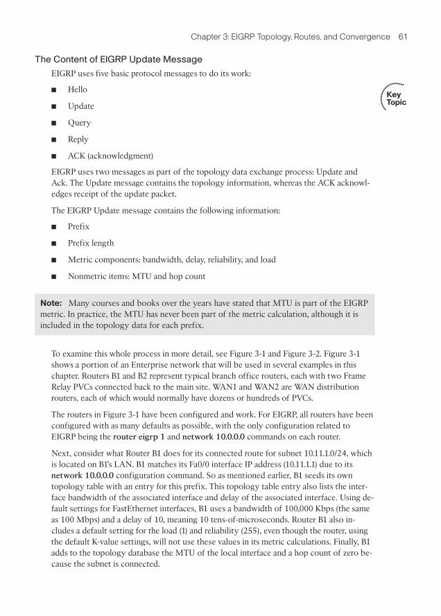
The Content of EIGRP Update Message
EIGRP uses five basic protocol messages to do its work:
■ Hello
■ Update
■ Query
■ Reply
■ ACK (acknowledgment)
EIGRP uses two messages as part of the topology data exchange process: Update andAck. The Update message contains the topology information, whereas the ACK acknowl-edges receipt of the update packet.
The EIGRP Update message contains the following information:
■ Prefix
■ Prefix length
■ Metric components: bandwidth, delay, reliability, and load
■ Nonmetric items: MTU and hop count
Note: Many courses and books over the years have stated that MTU is part of the EIGRPmetric. In practice, the MTU has never been part of the metric calculation, although it isincluded in the topology data for each prefix.
To examine this whole process in more detail, see Figure 3-1 and Figure 3-2. Figure 3-1shows a portion of an Enterprise network that will be used in several examples in thischapter. Routers B1 and B2 represent typical branch office routers, each with two FrameRelay PVCs connected back to the main site. WAN1 and WAN2 are WAN distributionrouters, each of which would normally have dozens or hundreds of PVCs.
The routers in Figure 3-1 have been configured and work. For EIGRP, all routers have beenconfigured with as many defaults as possible, with the only configuration related toEIGRP being the router eigrp 1 and network 10.0.0.0 commands on each router.
Next, consider what Router B1 does for its connected route for subnet 10.11.1.0/24, whichis located on B1’s LAN. B1 matches its Fa0/0 interface IP address (10.11.1.1) due to itsnetwork 10.0.0.0 configuration command. So as mentioned earlier, B1 seeds its owntopology table with an entry for this prefix. This topology table entry also lists the inter-face bandwidth of the associated interface and delay of the associated interface. Using de-fault settings for FastEthernet interfaces, B1 uses a bandwidth of 100,000 Kbps (the sameas 100 Mbps) and a delay of 10, meaning 10 tens-of-microseconds. Router B1 also in-cludes a default setting for the load (1) and reliability (255), even though the router, usingthe default K-value settings, will not use these values in its metric calculations. Finally, B1adds to the topology database the MTU of the local interface and a hop count of zero be-cause the subnet is connected.
Key Topic

62 CCNP ROUTE 642-902 Official Certification Guide
Note: All WAN IP addresses begin with 10.1
10.9.1.1/24
Fa0/0
10.9.1.2/24
Fa0/0
10.11.1.1
Fa0/0
10.12.1.1
Fa0/0
WAN1B1
WAN2B2
1.2S0/0/0.1
2.6S0/0/0.2
2.2S0/0/0.2
1.6S0/0/0.1
1.5S0/0/0.2
2.1S0/0/0.1
1.1S0/0/0.1
2.5S0/0/0.2
Figure 3-1 Typical WAN Distribution and Branch Office Design
1
2
3
Update:Subnet 10.11.1.0/24Delay 10Bandwidth 100,000(MTU, Load,Reliability, Hops)
Update:Subnet 10.11.1.0/24Delay 2010Bandwidth 1544(MTU, Load,Reliability, Hops)
Topology Table:Subnet 10.11.1.0/24Delay = 10 + 2000 = 2010Bandwidth = Min(100,000or 1544)(MTU, Load, Reliability, Hops)
B1 WAN1Interface Settings:Delay 10
Bandwidth 100,000
Interface S0/0/0.1Delay 2000
Bandwidth 1544
Figure 3-2 Contents of EIGRP Update Messages
Now that B1 has added some topology information to its EIGRP topology database, Figure3-2 shows how B1 propagates the topology information to router WAN1 and beyond.
The steps in Figure 3-2 can be explained as follows:
Step 1. B1 advertises the prefix (10.11.1.0/24) using an EIGRP Update message. Themessage includes the four metric components, plus MTU and hop count–essentially the information in B1’s EIGRP topology table entry for this prefix.
Step 2. WAN1 receives the Update message and adds the topology information for10.11.1.0/24 to its own EIGRP topology table, with these changes:
a. WAN1 considers the interface on which it received the Update (S0/0/0.1) tobe the outgoing interface of a potential route to reach 10.11.1.0/24.
b. WAN1 adds the delay of S0/0/0.1 (2000 tens-of-microseconds per Figure 3-2)to the delay listed in the Update message.
c. WAN1 compares the bandwidth of S0/0/0.1 (1544 Kbps per Figure 3-2) tothe bandwidth listed in the Update message (100,000 Kbps) and choosesthe lower value (1544) as the bandwidth for this route.
.

! On Router B1: !!!!!!!!!!!!!!!!!!!!!!!!!!!!!!!!!!!!!!!!!
B1#show ip eigrp topology 10.11.1.0/24
IP-EIGRP (AS 1): Topology entry for 10.11.1.0/24
State is Passive, Query origin flag is 1, 1 Successor(s), FD is 28160
Routing Descriptor Blocks:
0.0.0.0 (FastEthernet0/0), from Connected, Send flag is 0x0
Composite metric is (28160/0), Route is Internal
Vector metric:
Minimum bandwidth is 100000 Kbit
Total delay is 100 microseconds
Reliability is 255/255
Load is 1/255
Minimum MTU is 1500
Hop count is 0
! On Router WAN1: !!!!!!!!!!!!!!!!!!!!!!!!!!!!!!!!!!!!!!!!!
WAN1#show ip eigrp topology 10.11.1.0/24
IP-EIGRP (AS 1): Topology entry for 10.11.1.0/24
State is Passive, Query origin flag is 1, 1 Successor(s), FD is 2172416
Routing Descriptor Blocks:
10.1.1.2 (Serial0/0/0.1), from 10.1.1.2, Send flag is 0x0
Composite metric is (2172416/28160), Route is Internal
Vector metric:
Minimum bandwidth is 1544 Kbit
Total delay is 20100 microseconds
Chapter 3: EIGRP Topology, Routes, and Convergence 63
d. WAN1 also updates load (highest value), reliability (lowest value), and MTU(lowest value) based on similar comparisons, and adds 1 to the hop count.
Step 3. WAN1 then sends an Update to its neighbors, with the metric componentslisted in its own topology table.
This example provides a good backdrop to understand how EIGRP uses cumulative delayand minimum bandwidth in its metric calculation. Note that at Step 2, router WAN1 addsto the delay value but does not add the bandwidth. For bandwidth, WAN1 simply choosesthe lowest bandwidth, comparing the bandwidth of its own interface (S0/0/0.1) with thebandwidth listed in the received EIGRP update.
Next, consider this logic on other routers—not shown in the figure—as WAN1 floods thisrouting information throughout the Enterprise. WAN1 then sends this topology informa-tion to another neighbor, and that router sends the topology data to another, and so on. Ifbandwidth of those links was 1544 or higher, the bandwidth setting used by those routerswould remain the same, because each router would see that the routing update’s band-width (1544 Kbps) was lower than the link’s bandwidth. However, each router would addsomething to the delay.
As a final confirmation of the contents of this Update process, Example 3-1 shows the de-tails of the EIGRP topology database for prefix 10.11.1.0/24 on both B1 and WAN1.
Example 3-1 Topology Database Contents for 10.11.1.0/24, on B1 and WAN1

64 CCNP ROUTE 642-902 Official Certification Guide
Reliability is 255/255
Load is 1/255
Minimum MTU is 1500
Hop count is 1
The highlighted portions of output match the details shown in Figure 3-2, but with onetwist relating to the units on the delay setting. The IOS delay command, which lets you setthe delay, along with the data stored in the EIGRP topology database, use a unit of tens-of-microsecond. However, the show interfaces and show ip eigrp topology commandslist delay in a unit of microseconds. For example, WAN1’s listing of “20100 microseconds”matches the “2010 tens-on-microseconds” shown in Figure 3-2.
The EIGRP Update Process
So far, this chapter has focused on the detailed information EIGRP exchanges with aneighbor about each prefix. This section takes a broader look at the process.
When EIGRP neighbors first become neighbors, they begin exchanging topology infor-mation using Update messages using these rules:
■ When a neighbor first comes up, the routers exchange full updates, meaning therouters exchange all topology information.
■ After all prefixes have been exchanged with a neighbor, the updates cease with thatneighbor if no changes occur in the network. There is no periodic reflooding oftopology data.
■ If something changes–for example, one of the metric components change, links fail,links recover, new neighbors advertise additional topology information–the routerssend partial updates about only the prefixes whose status or metric components havechanged.
■ If neighbors fail and then recover, or new neighbor adjacencies are formed, full up-dates occur over these adjacencies.
■ EIGRP uses Split Horizon rules on most interfaces by default, which impacts exactlywhich topology data EIGRP sends during both full and partial updates.
Split Horizon, the last item in the list, needs a little more explanation. Split Horizon limitsthe prefixes that EIGRP advertises out an interface. Specifically, if the currently best routefor a prefix lists a particular outgoing interface, Split Horizon means that EIGRP will notinclude that prefix in the Update sent out that same interface. For example, router WAN1uses S0/0/0.1 as its outgoing interface for subnet 10.11.1.0/24, so WAN1 would not adver-tise prefix 10.11.1.0/24 in its Update messages sent out S0/0/0.1.
Note: Route summarization and route filtering, as explained in Chapter 4, “EIGRP RouteSummarization and Filtering,” also affect which subsets of the topology table are flooded.
Key Topic

Chapter 3: EIGRP Topology, Routes, and Convergence 65
To send the Updates, EIGRP uses the Reliable Transport Protocol (RTP) to send theEIGRP updates and confirm their receipt. On point-to-point topologies such as seriallinks, MPLS VPN, and Frame Relay when using point-to-point subinterfaces, the EIGRPUpdate and ACK messages use a simple process of acknowledging each Update with anACK. On multiaccess data links, EIGRP typically sends Update messages to multicastaddress 224.0.0.10 and expects a unicast EIGRP ACK message from each neighbor in reply.RTP manages that process, setting timers so that the sender of an Update waits a reason-able time, but not too long, before deciding whether all neighbors received the Update orwhether one or more neighbors did not reply with an ACK.
Although EIGRP relies on the RTP process, network engineers cannot manipulate howit works.
WAN Issues for EIGRP Topology Exchange
With all default settings, after you enable EIGRP on all the interfaces in an internetwork,the topology exchange process typically does not pose any problems. However, a fewscenarios exist, particularly on Frame Relay, which can cause problems. This section sum-marizes two issues and shows the solution.
Split Horizon Default on Frame Relay Multipoint Subinterfaces
IOS support for Frame Relay allows the configuration of IP addresses on the physical se-rial interface, multipoint subinterfaces, and point-to-point subinterfaces. Additionally, IPpackets can be forwarded over a PVC even when the routers on the opposite ends do nothave to use the same interface or subinterface type. As a result, many small intricacies ex-ist in the operation of IP and IP routing protocols over Frame Relay, particularly related todefault settings on different interface types.
Frame Relay supports several reasonable configuration options using different interfacesand subinterfaces, each meeting different design goals. For instance, if the design includesa few centralized WAN distribution routers, with PVCs connecting each branch router toeach distribution router, both distribution and branch routers might use point-to-pointsubinterface. Such a choice makes the Layer 3 topology simple, with all links acting likepoint-to-point links from a Layer 3 perspective. This choice also removes issues such asSplit Horizon.
In some cases, a design might include a small set of routers that have a full mesh of PVCsconnecting each. In this case, multipoint subinterfaces might be used, consuming a singlesubnet, reducing the consumption of the IP address space. This choice also reduces thenumber of subinterfaces.
Both options–using point-to-point subinterfaces or using multipoint subinterfaces–havelegitimate reasons for being used. However, when using the multipoint subinterfaceoption, a particular EIGRP issue can occur when the following are true:
■ Three or more routers, over Frame Relay, are configured as part of a single subnet.
■ The routers use multipoint interfaces.
■ Either permanently or for a time, a full mesh of PVCs between the routers doesnot exist.

66 CCNP ROUTE 642-902 Official Certification Guide
No PVCNo HellosNo Neighbors
10.11.1.0/24
WAN1B1S0/0/0.9
B2
10.1.1.2/29
10.1.1.3/29
1
Update 10.11.1.0/24 . . .2
10.1.1.1/29
. . . But not here!(Split Horizon)
10.12.1.0/24
Figure 3-3 Partial Mesh, Central Sites (WAN1) Uses Multipoint Subinterface
For example, consider Router WAN1 shown earlier in Figure 3-1 and referenced again inFigure 3-3. In the earlier configurations, the WAN distribution routers and branch routersall used point-to-point subinterfaces and a single subnet per VC. To see the problem raisedin this section, consider that same internetwork, but now the engineer has chosen to con-figure WAN1 to use a multipoint subinterface and a single subnet for WAN1, B1, and B2,as shown in Figure 3-3.
The first issue to consider in this design is that B1 and B2 will not become EIGRP neigh-bors with each other, as noted with Step 1 in the figure. EIGRP routers must be reachableusing Layer 2 frames before they can exchange EIGRP Hello messages and become EIGRPneighbors. In this case, there is no PVC between B1 and B2. B1 exchanges Hellos withWAN1, and become neighbors, as will B2 with WAN1. However, routers do not forwardreceived EIGRP Hellos, so WAN1 will not receive a Hello from B1 and forward it to B2 orvice versa. In short, although in the same subnet (10.1.1.0/29), B1 and B2 will not becomeEIGRP neighbors.
The second problem occurs due to Split Horizon logic on Router WAN1, as noted withStep 2 in the figure. As shown with Step 2 in the figure, B1 could advertise its routes toWAN1, and WAN1 could advertise those routes to B2–and vice versa. However, withdefault settings, WAN1 will not advertise those routes due to its default setting of SplitHorizon (a default interface subcommand setting of ip split-horizon eigrp asn.) As aresult, WAN1 receives the Update from B1 on its S0/0/0.9 subinterface, but Split Horizonprevents WAN1 from advertising that topology data to B2 in Updates sent out interfaceS0/0/0.9, and vice versa.
The solution is somewhat simple–just configure the no ip split-horizon eigrp asn com-mand on the multipoint subinterface on WAN1. The remote routers, B1 and B2 in this
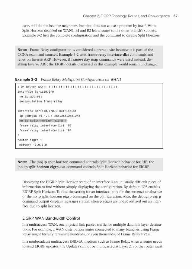
Chapter 3: EIGRP Topology, Routes, and Convergence 67
case, still do not become neighbors, but that does not cause a problem by itself. WithSplit Horizon disabled on WAN1, B1 and B2 learn routes to the other branch’s subnets.Example 3-2 lists the complete configuration and the command to disable Split Horizon:
Note: Frame Relay configuration is considered a prerequisite because it is part of theCCNA exam and courses. Example 3-2 uses frame-relay interface-dlci commands andrelies on Inverse ARP. However, if frame-relay map commands were used instead, dis-abling Inverse ARP, the EIGRP details discussed in this example would remain unchanged.
Example 3-2 Frame Relay Multipoint Configuration on WAN1
! On Router WAN1: !!!!!!!!!!!!!!!!!!!!!!!!!!!!!!!!!!!!!!!!!
interface Serial0/0/0
no ip address
encapsulation frame-relay
interface Serial0/0/0.9 multipoint
ip address 10.1.1.1 255.255.255.248
no ip split-horizon eigrp 1
frame-relay interface-dlci 103
frame-relay interface-dlci 104
!
router eigrp 1
network 10.0.0.0
Note: The [no] ip split-horizon command controls Split Horizon behavior for RIP; the[no] ip split-horizon eigrp asn command controls Split Horizon behavior for EIGRP.
Displaying the EIGRP Split Horizon state of an interface is an unusually difficult piece ofinformation to find without simply displaying the configuration. By default, IOS enablesEIGRP Split Horizon. To find the setting for an interface, look for the presence or absenceof the no ip split-horizon eigrp command on the configuration. Also, the debug ip eigrpcommand output displays messages stating when prefixes are not advertised out an inter-face due to split horizon.
EIGRP WAN Bandwidth Control
In a multiaccess WAN, one physical link passes traffic for multiple data link layer destina-tions. For example, a WAN distribution router connected to many branches using FrameRelay might literally terminate hundreds, or even thousands, of Frame Relay PVCs.
In a nonbroadcast multiaccess (NBMA) medium such as Frame Relay, when a router needsto send EIGRP updates, the Updates cannot be multicasted at Layer 2. So, the router must

68 CCNP ROUTE 642-902 Official Certification Guide
send a copy of the Update to each reachable neighbor. For a WAN distribution router withmany Frame Relay PVCs, the sheer amount of traffic sent over the Frame Relay access linkmight overload the link.
The EIGRP WAN bandwidth control allows the engineer to protect a multiaccess FrameRelay interface from being overrun with too much EIGRP message traffic. By default, arouter sends EIGRP messages out an interface but only up to 50 percent of the bandwidthdefined on the interface with the bandwidth command. The engineer can adjust this per-centage using the ip bandwidth-percent eigrp asn percent interface/subinterface sub-command. Regardless of the percentage, IOS then limits the rate of sending the EIGRPmessages so that the rate is not exceeded. To accomplish this, IOS queues the EIGRP mes-sages in memory, delaying them briefly.
The command to set the bandwidth percentage is simple, but there are a few caveats tokeep in mind when trying to limit the bandwidth consumed by EIGRP:
■ The IOS default for bandwidth on serial interfaces and subinterfaces is 1544 (Kbps).
■ EIGRP limits the consumed bandwidth based on the percentage of interface/subinterface bandwidth.
■ This feature keys on the bandwidth of the interface or subinterface through which theneighbor is reachable, so don’t set only the physical interface bandwidth and forgetthe subinterfaces.
■ Recommendation: Set the bandwidth of point-to-point links to the speed of theCommitted Information Rate (CIR) of the single PVC on the subinterface.
■ General recommendation: Set the bandwidth of multipoint subinterfaces to aroundthe total CIR for all VCs assigned to the subinterface.
■ Note that for multipoint subinterfaces, IOS WAN bandwidth control first divides the
subinterface bandwidth by the number of configured PVCs and then determinesthe EIGRP percentage based on that number.
For example, consider Figure 3-4, which shows a router with one multipoint subinterfaceand one point-to-point subinterface. With the configuration shown in Example 3-3,WAN1 uses the following bandwidth, at most, with each neighbor:
■ B1, B2, and B3: 20 Kbps (20% of 300Kbps / 3 VCs)
■ B4: 30 Kbps (30% of 100 Kbps)
Example 3-3 Configuration of WAN1, One Multipoint, One Point-to-Point
! On Router WAN1: !!!!!!!!!!!!!!!!!!!!!!!!!!!!!!!!!!!!!!!!!
interface Serial0/0/0.20 multipoint
ip address 172.16.1.1 255.255.255.240
frame-relay interface-dlci 201
frame-relay interface-dlci 202
frame-relay interface-dlci 203

Chapter 3: EIGRP Topology, Routes, and Convergence 69
S0/0/0.20 Multipoint
S0/0/0.21 Point-to-PointWAN1
B1
B2
B3
B4
Figure 3-4 WAN1, One Multipoint, One Point-to-Point
bandwidth 300
ip bandwidth-percent eigrp 1 20
!
interface Serial0/0/0.21 point-to-point
ip address 172.16.1.17 255.255.255.252
frame-relay interface-dlci 221
bandwidth 100
ip bandwidth-percent eigrp 1 30
Building the IP Routing Table
An EIGRP router builds IP routing table entries by processing the data in the topologytable. Unlike OSPF, which uses a computationally complex SPF process, EIGRP uses acomputationally simple process to determine which, if any, routes to add to the IP routingtable for each unique prefix/length. This part of the chapter examines how EIGRP choosesthe best route for each prefix/length and then examines several optional tools that can in-fluence the choice of routes to add to the IP routing table.
Calculating the Metrics: Feasible Distance and Reported Distance
The EIGRP topology table entry, for a single prefix/length, lists one or more possibleroutes. Each possible route lists the various component metric values–bandwidth, delay,and so on. Additionally, for connected subnets, the database entry lists an outgoing inter-face. For routes not connected to the local router, in addition to an outgoing interface, thedatabase entry also lists the IP address of the EIGRP neighbor that advertised the route.
EIGRP routers calculate an integer metric based on the metric components. Interestingly,an EIGRP router does this calculation both from its own perspective and from the per-spective of the next-hop router of the route. The two calculated values are
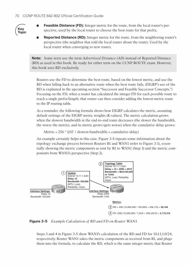
70 CCNP ROUTE 642-902 Official Certification Guide
1
2
3
4
Update:Subnet 10.11.1.0/24Delay 10Bandwidth 100,000(MTU, Load,Reliability, Hops)
Topology Table:Subnet 10.11.1.0/24Delay = 10 + 2000 = 2010Bandwidth = Min(100,000or 1544)(MTU, Load, Reliability, Hops)
B1 WAN1
Metrics:
RD = 256 (10,000,000 / 100,000) + 256 (10) = 28,160
FD =256 (10,000,000 / 1,544) + 256 (2010) = 2,172,416
Interface Settings:Delay 10
Bandwidth 100,000
Interface Settings:Delay 2000
Bandwidth 1544
Figure 3-5 Example Calculation of RD and FD on Router WAN1
■ Feasible Distance (FD): Integer metric for the route, from the local router’s per-spective, used by the local router to choose the best route for that prefix.
■ Reported Distance (RD): Integer metric for the route, from the neighboring router’sperspective (the neighbor that told the local router about the route). Used by thelocal router when converging to new routes.
Note: Some texts use the term Advertised Distance (AD) instead of Reported Distance(RD) as used in this book. Be ready for either term on the CCNP ROUTE exam. However,this book uses RD exclusively.
Routers use the FD to determine the best route, based on the lowest metric, and use theRD when falling back to an alternative route when the best route fails. (EIGRP’s use of theRD is explained in the upcoming section “Successor and Feasible Successor Concepts.”)Focusing on the FD, when a router has calculated the integer FD for each possible route toreach a single prefix/length, that router can then consider adding the lowest-metric routeto the IP routing table.
As a reminder, the following formula shows how EIGRP calculates the metric, assumingdefault settings of the EIGRP metric weights (K-values). The metric calculation growswhen the slowest bandwidth in the end-to-end route decreases (the slower the bandwidth,the worse the metric), and its metric grows (gets worse) when the cumulative delay grows:
Metric = 256 * ((107 / slowest-bandwidth) + cumulative-delay)
An example certainly helps in this case. Figure 3-5 repeats some information about thetopology exchange process between Routers B1 and WAN1 (refer to Figure 3-1), essen-tially showing the metric components as sent by B1 to WAN1 (Step 1) and the metric com-ponents from WAN1’s perspective (Step 2).
Steps 3 and 4 in Figure 3-5 show WAN1’s calculation of the RD and FD for 10.11.1.0/24,respectively. Router WAN1 takes the metric components as received from B1, and plugsthem into the formula, to calculate the RD, which is the same integer metric that Router
Key Topic

Chapter 3: EIGRP Topology, Routes, and Convergence 71
B1 would have calculated as its FD. Step 4 shows the same formula but with the metriccomponents as listed at Step 2–after the adjustments made on WAN1. Step 4 showsWAN1’s FD calculation, which is much larger due to the much lower constraining band-width plus the much larger cumulative delay.
WAN1 chooses its best route to reach 10.11.1.0/24 based on the lowest FD among all pos-sible routes. Looking back to the much more detailed Figure 3-1, presumably a couple ofother routes might have been possible, but WAN1 happens to choose the route shown inFigure 3-5 as its best route. As a result, WAN1’s show ip route command lists the FD cal-culated in Figure 3-5 as the metric for this route, as shown in Example 3-4.
Example 3-4 Router WAN1’s EIGRP Topology and IP Route Information for 10.11.1.0/24
! Below, note that WAN1’s EIGRP topology table lists two possible next-hop
! routers: 10.1.1.2 (B1) and 10.9.1.2 (WAN2). The metric for each route,
! the first number in parenthesis, shows that the lower metric route is the one
! through 10.1.1.2 as next-hop. Also note that the metric components
! match Figure 3-5.
!
WAN1#show ip eigrp topo 10.11.1.0/24
IP-EIGRP (AS 1): Topology entry for 10.11.1.0/24
State is Passive, Query origin flag is 1, 1 Successor(s), FD is 2172416
Routing Descriptor Blocks:
10.1.1.2 (Serial0/0/0.1), from 10.1.1.2, Send flag is 0x0
Composite metric is (2172416/28160), Route is Internal
Vector metric:
Minimum bandwidth is 1544 Kbit
Total delay is 20100 microseconds
Reliability is 255/255
Load is 1/255
Minimum MTU is 1500
Hop count is 1
10.9.1.2 (FastEthernet0/0), from 10.9.1.2, Send flag is 0x0
Composite metric is (2174976/2172416), Route is Internal
Vector metric:
Minimum bandwidth is 1544 Kbit
Total delay is 20200 microseconds
Reliability is 255/255
Load is 1/255
Minimum MTU is 1500
Hop count is 2
!
! The next command not only lists the IP routing table entry for 10.11.1.0/24,
! it also lists the metric (FD), and components of the metric.
!
WAN1#show ip route 10.11.1.0
Routing entry for 10.11.1.0/24

72 CCNP ROUTE 642-902 Official Certification Guide
Known via “eigrp 1”, distance 90, metric 2172416, type internal
Redistributing via eigrp 1
Last update from 10.1.1.2 on Serial0/0/0.1, 00:02:42 ago
Routing Descriptor Blocks:
* 10.1.1.2, from 10.1.1.2, 00:02:42 ago, via Serial0/0/0.1
Route metric is 2172416, traffic share count is 1
Total delay is 20100 microseconds, minimum bandwidth is 1544 Kbit
Reliability 255/255, minimum MTU 1500 bytes
Loading 1/255, Hops 1
!
! Below, the route for 10.11.1.0/24 is again listed, with the metric (FD), and
! the same next-hop and outgoing interface information.
!
WAN1#show ip route eigrp
10.0.0.0/8 is variably subnetted, 7 subnets, 2 masks
D 10.11.1.0/24 [90/2172416] via 10.1.1.2, 00:10:40, Serial0/0/0.1
D 10.12.1.0/24 [90/2172416] via 10.1.1.6, 00:10:40, Serial0/0/0.2
D 10.1.2.0/30 [90/2172416] via 10.9.1.2, 00:10:40, FastEthernet0/0
D 10.1.2.4/30 [90/2172416] via 10.9.1.2, 00:10:40, FastEthernet0/0
EIGRP Metric Tuning
EIGRP metrics can be changed using several methods: setting interface bandwidth, settinginterface delay, changing the metric calculation formula by configuring k-values, and evenby adding to the calculated metric using offset-lists. In practice, the most reasonable andcommonly used methods are to set the interface delay and the interface bandwidth. Thissection examines all the methods, in part so you will know which useful tools exist, and inpart to make you aware of some other design issues that then might impact the routeschosen by EIGRP.
Configuring Bandwidth and Delay
The bandwidth and delay interface subcommands set the bandwidth and delay associatedwith the interface. The commands themselves require little thought, other than keepingthe units straight. The unit for the bandwidth command is Kilobits/second, and the delaycommand uses a unit of tens-of-microseconds.
If a design requires that you influence the choice of route by changing bandwidth or de-lay, setting the delay value is typically the better choice. IOS uses the bandwidth settingof an interface for many other reasons: calculating interface utilization, as the basis forseveral QoS parameters, and for SNMP statistics reporting. However, the delay setting haslittle influence on other IOS features besides EIGRP, so the better choice when influenc-ing EIGRP metrics is to tune the delay.
Table 3-2 lists some of the common default values for both bandwidth and delay. As a re-minder, show commands list the bandwidth in Kbps, which matches the bandwidth com-mand, but lists the delay in microseconds, which does not match the tens-of-microsecondsunit of the delay command.

Chapter 3: EIGRP Topology, Routes, and Convergence 73
Note that on LAN interfaces that can run at different speeds, the bandwidth and delaysettings default based on the current actual speed of the interface.
Choosing Bandwidth Settings on WAN Subinterfaces
Frame Relay and Metro Ethernet installations often use an access link with a particularphysical sending rate–clock rate if you will–but with the contracted speed, over time, be-ing more or less than the speed of the link. For example, with Frame Relay, the providermay supply a full T1 access link, so configuring bandwidth 1544 for such an interface isreasonable. However, the subinterfaces have one or more PVCs associated with them, andthose PVCs each have Committed Information Rates (CIR) that are typically less than theaccess link’s clock speed. However, the cumulative CIRs for all PVC often exceeds theclock rate of the physical interface. Conversely, MetroE designs use Ethernet access linksof 10 Mbps, 100 Mbps, or 1 Gbps actual link speed, but often the business contract limitsthe amount of traffic to some number below that link speed.
Choosing a useful interface bandwidth setting on the subinterfaces in a Frame Relay orMetroE design requires some thought, with most of the motivations for choosing onenumber or another being unrelated to EIGRP. For example, imagine the network shown inFigure 3-6. Router WAN1 has a single T1 (1.544 Mbps) access link. That interface has onemultipoint subinterface, with three PVCs assigned to it. It also has nine other point-to-point subinterfaces, each with a single PVC assigned.
For the sake of discussion, the design in Figure 3-6 oversubscribes the T1 access link offRouter WAN1 by a 2:1 factor. Assume all 12 PVCs have a CIR of 256 Kbps, making the to-tal bandwidth for the 12 PVCs roughly 3 Mbps. The design choice to oversubscribe the ac-cess link may be reasonable given the statistical chance of all sites sending at the same time.
Now imagine that Router WAN1 has been configured with subinterfaces as shown inthe figure:
■ S0/0/0.20 - multipoint, 3 PVCs
■ S0/0/0.21 through S0/0/0.29 – point-to-point, 1 PVC each
Next, consider the options for setting the bandwidth command’s value on these 10 subin-terfaces. The point-to-point subinterfaces could be set to match the CIR of each PVC (256Kbps in this example). You could choose to set the bandwidth based on the CIR of allcombined PVCs on the multipoint subinterface–in this case, setting bandwidth 768 onmultipoint subinterface s0/0/0.20. However, these bandwidths would total about 3Mbps–twice the actual speed of WAN1’s access link. Alternatively, you could set the vari-ous bandwidths so that the total matches the 1.5 Mbps of the access link. Or you could
Table 3-2 Common Defaults for Bandwidth and Delay
Interface Type Bandwidth (Kbps) Delay (Microseconds)
Serial 1544 20,000
GigE 1,000,000 10
FastE 100,000 100
Ethernet 10,000 1000

74 CCNP ROUTE 642-902 Official Certification Guide
S0/0/0.20 Multipoint
S0/0/0.21 Point-to-Point
S0/0/0.29 Point-to-Point WAN1
B1
B2
B3
B4
B12
Figure 3-6 One Multipoint and Nine Point-to-Point Subinterfaces
split the difference, knowing that during times of low activity to most sites that the siteswith active traffic get more than their CIR’s worth of capacity anyway.
As mentioned earlier, these bandwidth settings impact much more than EIGRP. The set-tings impact interface statistics, both in show commands and in SNMP reporting. Theyimpact QoS features to some extent as well. Given that the better option for settingEIGRP metrics is to set the interface delay, EIGRP metric tuning may not be the drivingforce behind the decision as to what bandwidth values to use. However, some installationsmay change these values over time while trying to find the right compromise numbers forfeatures other than EIGRP. So, you need to be aware that changing those values may re-sult in different EIGRP metrics and impact the choices of best routes.
Similar issues exist on the more modern Layer 2 WAN services like MetroE, particularlywith the multipoint design of VPLS. Figure 3-7 shows a design that might exist aftermigrating the internetwork of Figure 3-6 to VPLS. Router WAN1 has been replaced by aLayer 3 switch, using a Gigabit interface to connect to the VPLS service. The remote sitesmight use the same routers as before, using a FastEthernet interface, or might be replacedwith Layer 3 switch hardware as well.
Concentrating on the mechanics of what happens at the central site, WAN1 might use802.1Q trunking. With 12 remote sites, WAN1 configures 12 VLAN interfaces, one perVLAN, with a different subnet used for the connection to each remote branch. Such adesign, from a Layer 3 perspective, looks like the age-old Frame Relay design with apoint-to-point link from the main site to each remote branch.
Additionally, the VPLS business contract might specify that WAN1 cannot send morethan 200 Mbps of traffic into the VPLS cloud, with the excess being discarded by theVPLS service. To prevent unnecessary discards, the engineer likely configures a featurecalled shaping, which slows down the traffic leaving the Gi0/1 interface of WAN1(regardless of VLAN). To meet the goal of 200 Mbps, WAN1 would send only part of the
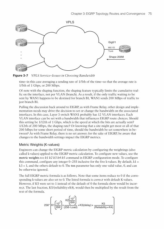
Chapter 3: EIGRP Topology, Routes, and Convergence 75
B1
B2
B12
•••
VPLS
WAN1802.1Q
Trunk
Gig0/1
Shape 200M
Figure 3-7 VPLS Service–Issues in Choosing Bandwidth
time–in this case averaging a sending rate of 1/5th of the time–so that the average rate is1/5th of 1 Gbps, or 200 Mbps.
Of note with the shaping function, the shaping feature typically limits the cumulative traf-fic on the interface, not per VLAN (branch). As a result, if the only traffic waiting to besent by WAN1 happens to be destined for branch B1, WAN1 sends 200 MBps of traffic tojust branch B1.
Pulling the discussion back around to EIGRP, as with Frame Relay, other design and imple-mentation needs may drive the decision to set or change the bandwidth on the associatedinterfaces. In this case, Layer 3 switch WAN1 probably has 12 VLAN interfaces. EachVLAN interface can be set with a bandwidth that influences EIGRP route choices. Shouldthis setting be 1/12th of 1 Gbps, which is the speed at which the bits are actually sent?1/12th of 200 Mbps, the shaping rate? Or knowing that a site might get most or all of that200 Mbps for some short period of time, should the bandwidth be set somewhere in be-tween? As with Frame Relay, there is no set answer; for the sake of EIGRP, be aware thatchanges to the bandwidth settings impact the EIGRP metrics.
Metric Weights (K-values)
Engineers can change the EIGRP metric calculation by configuring the weightings (alsocalled k-values) applied to the EIGRP metric calculation. To configure new values, use themetric weights tos k1 k2 k3 k4 k5 command in EIGRP configuration mode. To configurethis command, configure any integer 0–255 inclusive for the five k-values. By default, k1 =k3 = 1, and the others default to 0. The tos parameter has only one valid value, 0, and canbe otherwise ignored.
The full EIGRP metric formula is as follows. Note that some items reduce to 0 if the corre-sponding k-values are also set to 0. The listed formula is correct with default K-values.However, if K5 were set to 1 instead of the default of 0 the formula show would be incor-rect. The last fraction, K5/(reliability+K4), would then be multiplied by the result from therest of the formula.
256* 107
BWK5
(Reliability+K4)(256-Load)K1 + +K3(delay)+
107
BWK2

76 CCNP ROUTE 642-902 Official Certification Guide
EIGRP requires that two routers’ k-values match before those routers can become neigh-bors. Also note that Cisco recommends against using k-values k2, k4, and k5, because anonzero value for these parameters causes the metric calculation to include interfaceload and reliability. The load and reliability change over time, which causes EIGRP to re-flood topology data, and may cause routers to continually choose different routes (routeflapping).
Offset Lists
EIGRP Offset Lists, the final tool for manipulating the EIGRP metrics listed in this chap-ter, allow an engineer to simply add a value–an offset, if you will-to the calculated integermetric for a given prefix. To do so, an engineer can create and enable an EIGRP Offset Listthat defines the value to add to the metric, plus some rules regarding which routes shouldbe matched and therefore have the value added to their computed FD.
An Offset List can perform the following functions:
■ Match prefixes/prefix lengths using an IP ACL, so that the offset is applied only toroutes matched by the ACL with a permit clause
■ Match the direction of the Update message, either sent (out) or received (in)
■ Match the interface on which the Update is sent or received
■ Set the integer metric added to the calculation for both the FD and RD calculationsfor the route
The configuration itself uses the following command in EIGRP configuration mode, in ad-dition to any referenced IP ACLs:
offset-list {access-list-number | access-list-name} {in | out} offset [interface-
type interface-number]
For example, consider again branch office Router B1 in Figure 3-1, with its connection toboth WAN1 and WAN2 over a Frame Relay network. Formerly, WAN1 calculated a metricof 2,172,416 for its route, through B1, to subnet 10.11.1.0/24. (Refer to Figure 3-5 for themath behind WAN1’s calculation of its route to 10.11.1.0/24.) Router B1 also calculated avalue of 28,160 for the RD of that same direct route. Example 3-5 shows the addition ofan offset on WAN1, for received updates from Router B1.
Example 3-5 Inbound Offset of 3 on WAN1, for Updates Received on S0/0/0.1
WAN1(config)#access-list 11 permit 10.11.1.0
WAN1(config)#router eigrp 1
WAN1(config-router)#offset-list 11 in 3 Serial0/0/0.1
WAN1(config-router)#end
Mar 2 11:34:36.667: %DUAL-5-NBRCHANGE: IP-EIGRP(0) 1: Neighbor 10.1.1.2(Serial0/0/0.1) is resync: peer graceful-restart
WAN1#show ip eigrp topo 10.11.1.0/24
IP-EIGRP (AS 1): Topology entry for 10.11.1.0/24
State is Passive, Query origin flag is 1, 1 Successor(s), FD is 2172416

Chapter 3: EIGRP Topology, Routes, and Convergence 77
Routing Descriptor Blocks:
10.1.1.2 (Serial0/0/0.1), from 10.1.1.2, Send flag is 0x0
Composite metric is (2172419/28163), Route is Internal
Vector metric:
Minimum bandwidth is 1544 Kbit
Total delay is 20100 microseconds
Reliability is 255/255
Load is 1/255
Minimum MTU is 1500
Hop count is 1
! output omitted for brevity
The configuration has two key elements: ACL 11 and the offset-list command. ACL 11matches prefix 10.11.1.0, and that prefix only, with a permit clause. The offset-list 11 in 3s0/0/0.1 command tells Router WAN1 to examine all EIGRP Updates received on S0/0/0.1,and if prefix 10.11.1.0 is found, add 3 to the computed FD and RD for that prefix.
The show ip eigrp topology 10.11.1.0/24 command in Example 3-5 shows that the FDand RD, highlighted in parentheses, are now each three larger as compared with the earliermetrics.
Next, continuing this same example, Router B1 has now been configured to add an offset(4) in its sent updates to all routers, but for prefix 10.11.1.0/24 only.
Example 3-6 Outbound Offset of 4 on B1, for Updates Sent to All Neighbors, 10.11.1.0/24
B1(config)#access-list 12 permit 10.11.1.0
B1(config)#router eigrp 1
B1(config-router)#offset-list 12 out 4
B1(config-router)#end
B1#
! Back to router WAN1
WAN1#show ip eigrp topology
IP-EIGRP Topology Table for AS(1)/ID(10.9.1.1)
Codes: P - Passive, A - Active, U - Update, Q - Query, R - Reply,
r - reply Status, s - sia Status
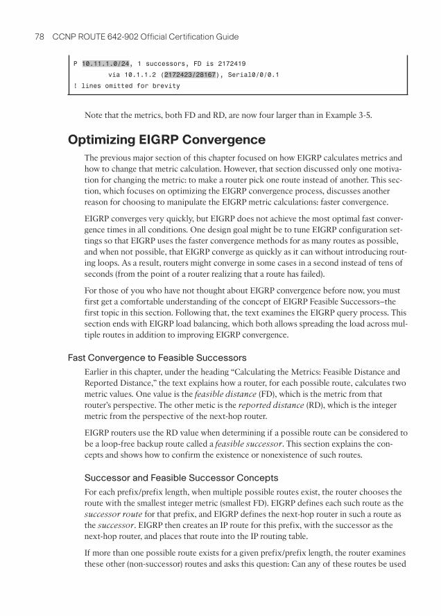
78 CCNP ROUTE 642-902 Official Certification Guide
P 10.11.1.0/24, 1 successors, FD is 2172419
via 10.1.1.2 (2172423/28167), Serial0/0/0.1
! lines omitted for brevity
Note that the metrics, both FD and RD, are now four larger than in Example 3-5.
Optimizing EIGRP Convergence
The previous major section of this chapter focused on how EIGRP calculates metrics andhow to change that metric calculation. However, that section discussed only one motiva-tion for changing the metric: to make a router pick one route instead of another. This sec-tion, which focuses on optimizing the EIGRP convergence process, discusses anotherreason for choosing to manipulate the EIGRP metric calculations: faster convergence.
EIGRP converges very quickly, but EIGRP does not achieve the most optimal fast conver-gence times in all conditions. One design goal might be to tune EIGRP configuration set-tings so that EIGRP uses the faster convergence methods for as many routes as possible,and when not possible, that EIGRP converge as quickly as it can without introducing rout-ing loops. As a result, routers might converge in some cases in a second instead of tens ofseconds (from the point of a router realizing that a route has failed).
For those of you who have not thought about EIGRP convergence before now, you mustfirst get a comfortable understanding of the concept of EIGRP Feasible Successors–thefirst topic in this section. Following that, the text examines the EIGRP query process. Thissection ends with EIGRP load balancing, which both allows spreading the load across mul-tiple routes in addition to improving EIGRP convergence.
Fast Convergence to Feasible Successors
Earlier in this chapter, under the heading “Calculating the Metrics: Feasible Distance andReported Distance,” the text explains how a router, for each possible route, calculates twometric values. One value is the feasible distance (FD), which is the metric from thatrouter’s perspective. The other metic is the reported distance (RD), which is the integermetric from the perspective of the next-hop router.
EIGRP routers use the RD value when determining if a possible route can be considered tobe a loop-free backup route called a feasible successor. This section explains the con-cepts and shows how to confirm the existence or nonexistence of such routes.
Successor and Feasible Successor Concepts
For each prefix/prefix length, when multiple possible routes exist, the router chooses theroute with the smallest integer metric (smallest FD). EIGRP defines each such route as thesuccessor route for that prefix, and EIGRP defines the next-hop router in such a route asthe successor. EIGRP then creates an IP route for this prefix, with the successor as thenext-hop router, and places that route into the IP routing table.
If more than one possible route exists for a given prefix/prefix length, the router examinesthese other (non-successor) routes and asks this question: Can any of these routes be used

Chapter 3: EIGRP Topology, Routes, and Convergence 79
immediately if the currently best route fails, without causing a routing loop? EIGRP runsa simple algorithm to identify which routes could be used without causing a routing loop,and EIGRP keeps these loop-free backup routes in its topology table. Then, if the succes-sor route (the best route) fails, EIGRP then immediately uses the best of these alternateloop-free routes for that prefix.
EIGRP calls these alternative, immediately usable, loop-free routes feasible successorroutes, because they can feasibly be used as a new successor route when the current suc-cessor route fails. The next-hop router of such a route is called the feasible successor.
Note: In general conversation, the term successor may refer to the route or specifically tothe next-hop router. Likewise, the term feasible successor may refer to the route, or thenext-hop router, of an alternative route.
A router determines if a route is a feasible successor based on the feasibility condition,defined as follows:
If a non-successor route’s RD is less than the FD, the route is a feasible successor route.
Although technically correct, the preceding definition is much more understandable withan example as shown in Figure 3-8. The figure illustrates how EIGRP figures out whichroutes are feasible successors for Subnet 1.
In Figure 3-8, Router E learns three routes to Subnet 1, from Routers B, C, and D. Aftercalculating each route’s metric, Router E finds that the route through Router D has thelowest metric. Router E adds this successor route for Subnet 1 to its routing table, asshown. The FD in this case for this successor route is 14,000.
EIGRP decides if a route can be a feasible successor if the reported distance for that route(the metric as calculated on that neighbor) is less than its own best computed metric (theFD). When that neighbor has a lower metric for its route to the subnet in question, thatroute is said to have met the feasibility condition.
Key Topic
Subnet 1 Metric 15,000
Route Through Router B — 19,000Route Through Router C — 17,500Route Through Router D — 14,000
Subnet 1 Metric 13,000
Subnet 1
Subnet 1 Metric 10,000
CE A
D
B
Route Through Router D — SuccessorRoute Through Router C — Feasible Successor(C’s RD is 13,000, which Is Less than E’s Metric)
Subnet 1 Metric 14,000, Through Router D
Router E Topology Table for Subnet 1
Router E Routing Table
Router E Calculates FD for Each Route:
Figure 3-8 Successors and Feasible Successors with EIGRP

80 CCNP ROUTE 642-902 Official Certification Guide
For example, Router E computes a metric (FD) of 14,000 on its successor route (throughRouter D). Router C’s computed metric–E’s RD for this alternate router through RouterC–is 13,000, which is lower than E’s FD (14,000). As a result, E knows that C’s best routefor this subnet could not possible point toward router E, so Router E believes that itsroute, to Subnet 1, through Router C, would not cause a loop. As a result, Router E marksits topology table entry for the route through Router C as a feasible successor route.
Conversely, E’s RD for the route through Router B, to Subnet 1, is 15,000, which is largerthan Router E’s FD of 14,000. So, this alternative route does not meet the feasibility condi-tion, so Router E does not consider the route through Router B a feasible successor route.
If the route to Subnet 1 through Router D fails, Router E can immediately put the routethrough Router C into the routing table without fear of creating a loop. Convergenceoccurs almost instantly in this case. However, if both C and D fail, E would not have a fea-sible successor route, and would have to do additional work, as described later in the sec-tion “Converging by Going Active,” before using the route through Router B.
By tuning EIGRP metrics, an engineer can create feasible successor routes in cases wherenone existed, improving convergence.
Verification of Feasible Successors
Determining which prefixes have both successor and feasible successor routes is some-what simple if you keep the following in mind:
■ The show ip eigrp topology command does not list all known EIGRP routes, but in-stead lists only successor and feasible successor routes.
■ The show ip eigrp topology all-links command lists all possible routes, includingthose that are neither successor nor feasible successor routes.
For example, consider Figure 3-9, which again focuses on Router WAN1’s route to RouterB1’s LAN subnet, 10.11.1.0/24. The configuration on all routers has reverted back to de-faults for all settings that impact the metric: default bandwidth and delay, no offset lists,and all interfaces are up.
Figure 3-9 shows the three topologically possible routes to reach 10.11.1.0/24, labeled 1, 2,and 3. Route 1, direct to Router B1, is the current successor. Route 3, which goes to an-other branch router, back to the main site, and then to Router B1, is probably a route youwould not want to use anyway. However, route 2, through WAN2, would be a reasonableback-up route.
If the PVC between WAN1 and B1 failed, WAN1 would converge to route 2 from thefigure. However, with all default settings, route 2 is not an FS route, as demonstrated inExample 3-7.
Example 3-7 Only a Successor Route on WAN1 for 10.11.1.0/24
WAN1#show ip eigrp topology
IP-EIGRP Topology Table for AS(1)/ID(10.9.1.1)
Key Topic

Chapter 3: EIGRP Topology, Routes, and Convergence 81
Note: All WAN IP addresses begin with 10.1
10.9.1.1/24
Fa0/0
10.9.1.2
10.11.1.1
Fa0/0
10.1.1.6
B110.1.1.2
1.5S0/0/0.2
1.1S0/0/0.1
1 2
WAN1
WAN2B2
3
Figure 3-9 Three Possible Routes from WAN1 to 10.11.1.0/24
Codes: P - Passive, A - Active, U - Update, Q - Query, R - Reply,
r - reply Status, s - sia Status
P 10.11.1.0/24, 1 successors, FD is 2172416
via 10.1.1.2 (2172416/28160), Serial0/0/0.1
! lines omitted for brevity; no other lines of output pertain to 10.11.1.0/24.
WAN1#show ip eigrp topology all-links
IP-EIGRP Topology Table for AS(1)/ID(10.9.1.1)
Codes: P - Passive, A - Active, U - Update, Q - Query, R - Reply,
r - reply Status, s - sia Status
P 10.11.1.0/24, 1 successors, FD is 2172416, serno 45
via 10.1.1.2 (2172416/28160), Serial0/0/0.1
via 10.9.1.2 (2174976/2172416), FastEthernet0/0
! lines omitted for brevity; no other lines of output pertain to 10.11.1.0/24.
A quick comparison of the two commands show that the show ip eigrp topology com-mand shows only one next-hop address (10.1.1.2), whereas the show ip eigrp topology all-links command shows two (10.1.1.2 and 10.9.1.2). The first command lists only successorand feasible successor routes, so in this case, only one such route for 10.11.1.0/24 exists—the successor route, direct to B1 (10.1.1.2).
The output of the show ip eigrp topology all-links command is particularly interesting inthis case. It lists two possible next-hop routers: 10.1.1.2 (B1) and 10.9.1.2 (WAN2). It does

82 CCNP ROUTE 642-902 Official Certification Guide
not list the route through Router B2 (10.1.1.6) at all, because B2’s current successor routefor 10.11.1.0/24 is through WAN1. EIGRP Split Horizon rules tell B2 to not advertise10.11.1.0/24 to WAN1.
Next, focus on the route labeled as option 2 in Figure 3-9, the route from WAN1, toWAN2, then to B1. Per the show ip eigrp topology all-links command, this route has anRD of 2,172,416–the second number in parenthesis as highlighted toward the end ofExample 3-7. WAN1’s successor route has a FD of that exact same value. So, this one pos-sible alternate route for 10.11.1.0/24, through WAN2, does not meet the feasibility condi-tion–but just barely. To be an FS route, the route’s RD must be less than the FD, and in thisexample, the two are equal.
To meet the design requirement for quickest convergence, you could use any method tomanipulate the metrics such that either WAN2’s metric for 10.11.1.0 is lower, or WAN1’smetric for its successor route is higher. Example 3-8 shows the results of simply addingback the offset-list on WAN1, as seen in Example 3-5, which increases WAN1’s metric by 3.
Example 3-8 Increasing WAN1’s Metric for 10.11.1.0/24, Creating an FS Route
WAN1#configure terminal
Enter configuration commands, one per line. End with CNTL/Z.
WAN1(config)#access-list 11 permit 10.11.1.0
WAN1(config)#router eigrp 1
WAN1(config-router)#offset-list 11 in 3 s0/0/0.1
WAN1(config-router)#^Z
WAN1#show ip eigrp topology
IP-EIGRP Topology Table for AS(1)/ID(10.9.1.1)
Codes: P - Passive, A - Active, U - Update, Q - Query, R - Reply,
r - reply Status, s - sia Status
P 10.11.1.0/24, 1 successors, FD is 2172419
via 10.1.1.2 (2172419/28163), Serial0/0/0.1
via 10.9.1.2 (2174976/2172416), FastEthernet0/0
! lines omitted for brevity; no other lines of output pertain to 10.11.1.0/24.
Note that now WAN1’s successor route FD is 2,172,419, which is higher than WAN2’s(10.9.1.2’s) RD of 2,172,416. As a result, WAN1’s route through WAN2 (10.9.1.2) now meetsthe feasibility condition. Also, the show ip eigrp topology command, which lists onlysuccessor and feasible successor routes, now lists this new feasible successor route. Alsonote that the output still states “1 successor,” so this counter indeed counts successorroutes and does not include FS routes.
When EIGRP on a router notices that a successor route has been lost, if a feasible succes-sor exists in the EIGRP topology database, EIGRP places that feasible successor route intothe routing table. The elapsed time from noticing that the route failed, until the route is re-placed, is typically less than 1 second. (A Cisco Live conference presentation asserts this
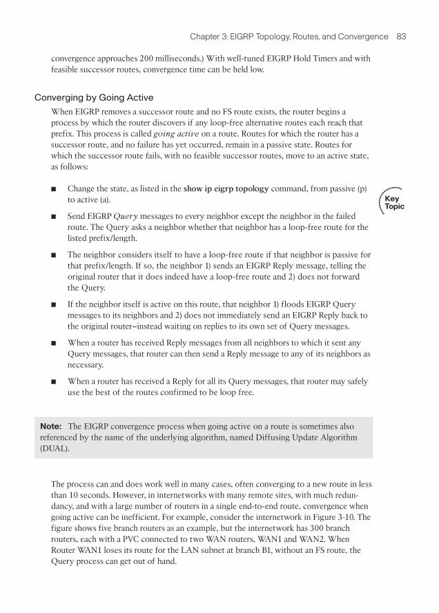
Chapter 3: EIGRP Topology, Routes, and Convergence 83
convergence approaches 200 milliseconds.) With well-tuned EIGRP Hold Timers and withfeasible successor routes, convergence time can be held low.
Converging by Going Active
When EIGRP removes a successor route and no FS route exists, the router begins aprocess by which the router discovers if any loop-free alternative routes each reach thatprefix. This process is called going active on a route. Routes for which the router has asuccessor route, and no failure has yet occurred, remain in a passive state. Routes forwhich the successor route fails, with no feasible successor routes, move to an active state,as follows:
■ Change the state, as listed in the show ip eigrp topology command, from passive (p)to active (a).
■ Send EIGRP Query messages to every neighbor except the neighbor in the failedroute. The Query asks a neighbor whether that neighbor has a loop-free route for thelisted prefix/length.
■ The neighbor considers itself to have a loop-free route if that neighbor is passive forthat prefix/length. If so, the neighbor 1) sends an EIGRP Reply message, telling theoriginal router that it does indeed have a loop-free route and 2) does not forwardthe Query.
■ If the neighbor itself is active on this route, that neighbor 1) floods EIGRP Querymessages to its neighbors and 2) does not immediately send an EIGRP Reply back tothe original router–instead waiting on replies to its own set of Query messages.
■ When a router has received Reply messages from all neighbors to which it sent anyQuery messages, that router can then send a Reply message to any of its neighbors asnecessary.
■ When a router has received a Reply for all its Query messages, that router may safelyuse the best of the routes confirmed to be loop free.
Key Topic
Note: The EIGRP convergence process when going active on a route is sometimes alsoreferenced by the name of the underlying algorithm, named Diffusing Update Algorithm(DUAL).
The process can and does work well in many cases, often converging to a new route in lessthan 10 seconds. However, in internetworks with many remote sites, with much redun-dancy, and with a large number of routers in a single end-to-end route, convergence whengoing active can be inefficient. For example, consider the internetwork in Figure 3-10. Thefigure shows five branch routers as an example, but the internetwork has 300 branchrouters, each with a PVC connected to two WAN routers, WAN1 and WAN2. WhenRouter WAN1 loses its route for the LAN subnet at branch B1, without an FS route, theQuery process can get out of hand.

84 CCNP ROUTE 642-902 Official Certification Guide
B2
B4
B3
B1
WAN1
B5
WAN2
Core1
Core2
Figure 3-10 Issues with Query Scope
The arrowed lines show WAN1’s Query messages and the reaction by several other routersto forward the Query messages. Although only 5 branch routers are shown, WAN1 wouldforward Query messages to 299 branch routers. WAN2 would do the same, assuming itsroute to B1’s LAN also failed. These branch routers would then send Query messages backto the WAN routers. The network would converge, but more slowly than if an FS routeexisted.
Note: EIGRP sends every Query and Reply message using RTP, so every message isacknowledged using an EIGRP ACK message.
By configuring EIGRP so that a router has FS routes for most routes, the whole Queryprocess can be avoided. However, in some cases, creating FS routes for all routes on allrouters is impossible, so engineers should take action to limit the scope of queries. Thenext two sections discuss two tools—stub routers and route summarization—that help re-duce the work performed by the DUAL algorithm and the scope of Query messages.
The Impact of Stub Routers on Query Scope
Some routers, by design, should not be responsible for forwarding traffic between differ-ent sites. For example, consider the familiar internetwork shown throughout this chapter,

Chapter 3: EIGRP Topology, Routes, and Convergence 85
most recently in Figure 3-10, and focus on the branch routers. If WAN2’s LAN interfacefailed, and WAN1’s PVC to B1 failed, then a route still exists from the core to branch B1’s10.11.1.0/24 subnet: WAN1–B2–WAN2–B1. (This is the same long route shown as route 3in Figure 3-9.) However, this long route consumes the link bandwidth between the coreand branch B2, and the traffic to/from B1 will be slower. Users at both branches will suffer,and these conditions may well be worse than just not using this long route.
Route filtering could be used to prevent WAN1 from learning such a route. However, us-ing route filtering would require a lot of configuration on all the branch routers, withspecifics for the subnets–and it would have to change over time. A better solution exists,which is to make the branch routers stub routers. EIGRP defines stub routers as follows:
A router that should not forward traffic between two remote EIGRP-learned subnets.
To accomplish this goal, the engineer configures the stub routers using the eigrp stubcommand. Stub routers do not advertise EIGRP-learned routes from one neighbor toother EIGRP neighbors. Additionally, and possibly more significantly, nonstub routersnote which EIGRP neighbors are stub routers, and the nonstub routers do not send Querymessages to the stub routers. This action greatly reduces the scope of Query messageswhen a route goes active, in addition to preventing the long, circuitous, and possiblyharmful route.
The eigrp stub command has several options. When issued simply as eigrp stub, therouter uses default parameters, which are the connected and summary options. (Note thatIOS adds these two parameters onto the command as added to the running-config.) Table3-3 lists the eigrp stub command options and explains some of the logic behind usingthem.
Note that stub routers still form neighborships, even in receive-only mode. The stub routersimply performs less work and reduces the Query Scope because neighbors will not sendthese routers any Query messages.
For example, Example 3-9 shows the eigrp stub connected command on Router B2, withthe results being noticable on WAN1 (show ip eigrp neighbors detail).
Key Topic
Key Topic
Table 3-3 Parameters on the eigrp stub Command
Option This router is allowed to...
Connected Advertise connected routes but only for interfaces matched with a networkcommand.
Summary Advertise auto-summarized or statically configured summary routes.
Static Advertises static routes, assuming the redistribute static command is config-ured.
Redistributed Advertises redistributed routes, assuming redistribution is configured.
Receive-only Does not advertise any routes. This option cannot be used with any otheroption.

86 CCNP ROUTE 642-902 Official Certification Guide
Example 3-9 Evidence of Router B2 as an EIGRP Stub Router
B2#configure terminal
B2(config)#router eigrp 1
B2(config-router)#eigrp stub connected
B2(config-router)#
Mar 2 21:21:52.361: %DUAL-5-NBRCHANGE: IP-EIGRP(0) 1: Neighbor 10.9.1.14(FastEthernet0/0.12) is down: peer info changed
! A message like the above occurs for each neighbor.
! Moving to router WAN1 next
WAN1#show ip eigrp neighbors detail
IP-EIGRP neighbors for process 1
H Address Interface Hold Uptime SRTT RTO Q Seq
(sec) (ms) Cnt Num
1 10.9.1.2 Fa0/0 11 00:00:04 7 200 0 588
Version 12.4/1.2, Retrans: 0, Retries: 0, Prefixes: 8
2 10.1.1.6 Se0/0/0.2 13 00:21:23 1 200 0 408
Version 12.4/1.2, Retrans: 2, Retries: 0, Prefixes: 2
Stub Peer Advertising ( CONNECTED ) Routes
Suppressing queries
0 10.9.1.6 Fa0/0.4 12 00:21:28 1 200 0 175
The Impact of Summary Routes on Query Scope
In addition to EIGRP stub routers, route summarization also limits EIGRP Query scopeand therefore improves convergence time. The reduction in Query scope occurs due to thefollowing rule:
If a router receives an EIGRP Query for a prefix/prefix length, does not have an exactlymatching (both prefix and prefix length) route, but does have a summary route that in-cludes the prefix/prefix length, that router immediately sends an EIGRP Reply and doesnot flood the Query to its own neighbors.
For example, consider Figure 3-11. Multilayer Switches C1 and C2 sit in the core of thenetwork shown in various other figures in this chapter, and both C1 and C2 run EIGRP.The IP subnetting design assigns all branch office LAN subnets from the range10.11.0.0/16 and 10.12.0.0/16. As such, Routers WAN1 and WAN2 advertise summaryroutes for these ranges, rather than for individual subnets. So, under normal operation,ignoring the whole Query scope issue, C1 and C2 would never have routes for individualbranch subnets like 10.11.1.0/24 but would have routes for 10.11.0.0/16 and 10.12.0.0/16.
The figure highlights three steps:
Step 1. WAN1 and WAN2 advertise summary routes, so that C1, C2, and all otherrouters in the core have a route for 10.11.0.0/16 but not a route for 10.11.1.0/24.
Step 2. Some time in the future, WAN1 loses its route for 10.11.1.0/24, so WAN1sends a Query for 10.11.1.0/24 to C1 and C2.
Key Topic
WAN1#show ip eigrp neighbors detail
IP-EIGRP neighbors for process 1
H Address Interface Hold Uptime SRTT RTO Q Seq
(sec) (ms) Cnt Num
1 10.9.1.2 Fa0/0 11 00:00:04 7 200 0 588
Version 12.4/1.2, Retrans: 0, Retries: 0, Prefixes: 8
2 10.1.1.6 Se0/0/0.2 13 00:21:23 1 200 0 408
Version 12.4/1.2, Retrans: 2, Retries: 0, Prefixes: 2
Stub Peer Advertising ( CONNECTED ) Routes
Suppressing queries
0 10.9.1.6 Fa0/0.4 12 00:21:28 1 200 0 175
Version 12.2/1.2, Retrans: 3, Retries: 0, Prefixes: 6

Chapter 3: EIGRP Topology, Routes, and Convergence 87
WAN1
WAN2
C1
C2
Update:10.11.0.1/1610.12.0.0/16
OtherCore
Routers
300BranchesAll LAN subnets
in ranges10.11.0.0/1610.12.0.0/16
1
Query:10.11.1.0/24?
2
Reply:Nope!
3
Update:10.11.0.1/1610.12.0.0/16
1
Figure 3-11 Route Summaries Limiting Query Scope
Step 3. C1 and C2 send an EIGRP Reply immediately afterward, because both do nothave a route for that specific prefix/length (10.11.1.0/24), but both do have asummary route (10.11.0.0/16) that includes that range of addresses.
Chapter 4, “EIGRP Route Summarization and Filtering,” explains the configuration ofEIGRP route summarization as an end to itself.
Stuck in Active
When a router notices a route failure and moves a route from passive to active state, thatrouter sends Query messages to its neighbors. With a sufficiently large network, particu-larly when routers exist several router hops away, the number of Queries may not only belarge, but there also may be a string of routers that all must wait on multiple Reply mes-sages before they can, in turn, issue a Reply. For example, in Figure 3-12, Router R1 mustwait on routers R11, R12, and R13 to send a Reply. R11 must wait on routers R21, R22,and R23. R21 must wait on three other routers, and so on–meaning that R1 may have towait quite a while before getting a response.
Although the design shown in Figure 3-12 is admittedly contrived, the point is that arouter may wait awhile before getting a Reply message in response to each Query messagefor an Active route. A router cannot use any alternative paths for that route until all suchReply messages have been received.
To deal with this potentially long time, IOS first sets a limit on how long it should take toreceive all such replies. That timer, called the active timer, is set to 3 minutes by default.(The timer can be configured for an entire EIGRP process using the timers active-timetime EIGRP subcommand, with a units of a number of minutes.) Routes for which arouter does not receive a Reply within the active timer are considered to be Stuck-in-Active (SIA) routes.
IOS has two major branches of logic when reacting to SIA routes. Earlier versions of IOStook a rather drastic action, bringing down the uncooperative neighbors that had yet tosend back an EIGRP Reply for that route. For example, in Figure 3-12, if R1 received Replymessages from R11 and R12, but not R13, and the active timer expired, R1 would bring

88 CCNP ROUTE 642-902 Official Certification Guide
24
25
26
12
21
22
23
11
27
28
29
13
1
Figure 3-12 Network Design That Causes Unreasonably Long Convergence
down the neighborship with R13. The active route would be considered to have failed,and all routes known through the failed neighbor would also be considered to havefailed–possibly generating more Query messages for other routes.
Later IOS versions (beginning in the 12.2 mainline) make an attempt to avoid failing theneighborship. At the halfway point through the Active timer–a seemingly long 90 secondsby default–a router sends an SIA-Query (Stuck-in-Active query) EIGRP message to eachneighbor that has yet to send back a Reply. The purpose of the message is to either get anSIA-Reply back, meaning that the neighbor really is still waiting for replies to its ownqueries, or to get nothing in reply. In the first case, because the neighbor is alive and stillworking, there is no need to kill the neighborship. In the second case, the neighbor wasnot able to reply, so the action of failing the neighborship is reasonable.
Unequal Metric Route Load Sharing
Convergence to a feasible successor route should happen within a second after a router re-alizes the successor route has failed. Even in large well-designed networks, particularly

Chapter 3: EIGRP Topology, Routes, and Convergence 89
with features like stub routers and route summarization in use, convergence can still hap-pen in a reasonable amount of time even when going active. The next feature, load sharing,takes convergence to another level, giving instantaneous convergence, while reaching othergoals as well.
IOS allows routing protocols to place multiple routes into the routing table for an in-dividual prefix/length. IOS then balances traffic across those routes, by default balancingtraffic on a per-destination IP address basis.
Load balancing, sometimes called load sharing, provides a primary benefit of making useof the available bandwidth, rather than using some links as simply backup links. Forexample, with the two-PVC designs repeatedly shown in this chapter (Figures 3-1, 3-9, and3-10), without load sharing, a branch router would send traffic over one PVC, but notboth. With load sharing, some traffic would flow over each PVC.
A useful secondary benefit–faster convergence–occurs when using load balancing. Byplacing multiple routes into the routing table for a single prefix, convergence happensessentially instantly. For example, if a branch router has two routes for each data centersubnet—one using each PVC that connects the branch to the core—and one of the routesfails, the other route is already in the routing table. In this case, the router does not needto look for FS routes nor go active on the route. The router uses the usual EIGRP conver-gence tools only when all such routes are removed from the routing table.
The load balancing configuration requires two commands, one of which already defaultsto a reasonable setting. First, you need to define the number of allowed routes for eachprefix/prefix length using the maximum-paths number EIGRP subcommand. The defaultsetting of 4 is often big enough, because most internetworks do not have enough redun-dancy to have more than four possible routes.
Note: The maximum number of paths varies based on IOS version and router platform.However, for the much older IOS versions, the maximum was 6 routes, with later versionstypically supporting 16 or more.
The second part of the load balancing configuration overcomes a challenge introduced byEIGRP’s metric calculation. The EIGRP integer metric calculation often results in 8-to-10-digit integer metrics, so the metrics of competing routes are seldom the exact same value.Calculating the exact same metric for different routes for the same prefix is statisticallyunlikely.
IOS includes the concept of EIGRP variance to overcome this problem. Variance lets youtell IOS that the EIGRP metrics can be close in value and still be considered worthy of be-ing added to the routing table—and you can define how close.
The variance multiplier EIGRP router subcommand defines an integer between 1 and128. The router then multiplies the variance times the successor route’s FD–the metric ofthe best route to reach that subnet. Any FS routes whose metric is less than or equal to theproduct of the variance times the FD are considered to be equal routes and may be placed into the routing table, up to the number of routes defined by the maximum-pathscommand.

90 CCNP ROUTE 642-902 Official Certification Guide
Subnet 1
Metric 50
R4 R2
R3
R1
Metric 120
Metric 90
Metric 30
Metric 60
Metric 40
Figure 3-13 Example of the Use of Variance
Table 3-4 Example of Routes Chosen as Equal Due to Variance
Next-
hop
Metric RD Added to Routing
Table at Variance 1?
Added to
Routing Table at
Variance 2?
Added to Routing
Table at Variance 3?
R1 50 30 Yes Yes Yes
R2 90 40 No Yes Yes
R3 120 60 No No No
For example, consider the example as shown in Figure 3-13 and Table 3-4. In this exam-ple, to keep the focus on the concepts, the metrics are small easy-to-compare numbers,rather than the usual large EIGRP metrics. The example focuses on R4’s three possibleroutes to reach Subnet 1. The figure shows the RD of each route next to Routers R1, R2,and R3, respectively.
Before considering the variance, note that in this case the route through R1 is the succes-sor route because it has the lowest metric. This also means that the FD is 50. The routethrough R2 is an FS route because its RD of 40 is less than the FD of 50. The routethrough R3 is not an FS route, because R3’s RD of 60 is more than the FD of 50.
At a default variance setting of 1, the metrics must be exactly equal to be consideredequal, so only the successor route is added to the routing table (the route through R1).With variance 2, the FD (50) is multiplied by the variance (2) for a product of 100. Theroute through R2, with FD 90, is less than 100, so R4 will add the route through R2 to therouting table as well. The router can then load balance traffic across these two routes.Table 3-4 summarizes these cases, plus one other, which is described after the table.
In the third case, with variance 3, the product of the FD (50) times 3 results equals 150.All three routes’ calculated metrics (their FD values) are less than 150. However, the route

Chapter 3: EIGRP Topology, Routes, and Convergence 91
through R3 is not an FS route, so it cannot be added to the routing table for fear ofcausing a routing loop. So, R4 adds only the routes through R1 and R2 to its IP routingtable. (Note that the variance and maximum-paths settings can be verified by using theshow ip protocols command.)
The following list summarizes the key points about variance:
■ The variance is multiplied by the current FD (the metric of the best route to reach thesubnet).
■ Any FS routes whose calculated metric is less than or equal to the product ofvariance times FD are added to the IP routing table, assuming the maximum-pathssetting allows more routes.
■ Routes that are neither successor nor feasible successor can never be added to the IProuting table, regardless of the variance setting.
When the routes have been added to the routing table, the router supports a couple ofmethods for how to load balance traffic across the routes. The router can balance the traf-fic proportionally with the metrics, meaning that lower metric routes send more packets.Also, the router can send all traffic over the lowest-metric route, with the other routes justbeing in the routing table for faster convergence in case the best route fails.
Key Topic
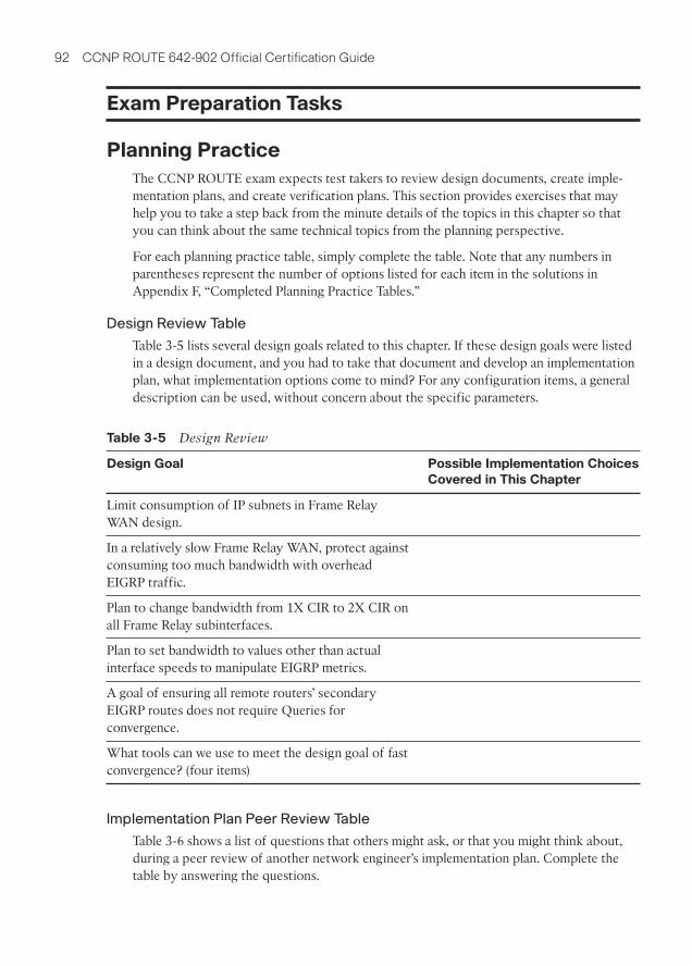
92 CCNP ROUTE 642-902 Official Certification Guide
Exam Preparation Tasks
Planning Practice
The CCNP ROUTE exam expects test takers to review design documents, create imple-mentation plans, and create verification plans. This section provides exercises that mayhelp you to take a step back from the minute details of the topics in this chapter so thatyou can think about the same technical topics from the planning perspective.
For each planning practice table, simply complete the table. Note that any numbers inparentheses represent the number of options listed for each item in the solutions inAppendix F, “Completed Planning Practice Tables.”
Design Review Table
Table 3-5 lists several design goals related to this chapter. If these design goals were listedin a design document, and you had to take that document and develop an implementationplan, what implementation options come to mind? For any configuration items, a generaldescription can be used, without concern about the specific parameters.
Implementation Plan Peer Review Table
Table 3-6 shows a list of questions that others might ask, or that you might think about,during a peer review of another network engineer’s implementation plan. Complete thetable by answering the questions.
Table 3-5 Design Review
Design Goal Possible Implementation Choices
Covered in This Chapter
Limit consumption of IP subnets in Frame RelayWAN design.
In a relatively slow Frame Relay WAN, protect againstconsuming too much bandwidth with overheadEIGRP traffic.
Plan to change bandwidth from 1X CIR to 2X CIR onall Frame Relay subinterfaces.
Plan to set bandwidth to values other than actualinterface speeds to manipulate EIGRP metrics.
A goal of ensuring all remote routers’ secondaryEIGRP routes does not require Queries forconvergence.
What tools can we use to meet the design goal of fastconvergence? (four items)

Chapter 3: EIGRP Topology, Routes, and Convergence 93
Create an Implementation Plan Table
To practice skills useful when creating your own EIGRP implementation plan, list in Table3-7 configuration commands related to the configuration of the following features. Youmay want to record your answers outside the book and set a goal to complete this table(and others like it) from memory during your final reviews before taking the exam.
Table 3-6 Notable Questions from This Chapter to Consider During an ImplementationPlan Peer Review
Question Answer
A Frame Relay multipoint interface, with 20 PVCs attached, hasa configuration for 10% of the bandwidth to be used for EIGRP.How much is allocated per PVC?
Could any planned topologies have EIGRP Split Horizon issues?
A configuration lists the no ip split-horizon command—whenwould that matter?
The plan calls for setting all EIGRP K-values to 1. What negativeeffect could this have on routes in the IP routing table?
The configuration uses offset lists. Will that impact the calcula-tion of FD and/or RD?
The plan lists a sample configuration migrating an interface fromdelay 20 to delay 200. How much will the metric go up?
The plan shows the use of the variance 4 command. What mustbe configured to add other routes to a routing table? (two items)
Table 3-7 Implementation Plan Configuration Memory Drill
Feature Configuration
Commands/Notes
Enabling EIGRP on interfaces
Enabling or disabling Split Horizon for EIGRP
Setting the Bandwidth consumed by EIGRP on an interface
Setting an interface’s logical bandwidth
Setting an interface’s logical delay
K-values
Configuring an EIGRP offset list that matches a prefix
Configuring an EIGRP offset list that matches a prefix andprefix length
Configuring unequal cost load balancing
Configure an EIGRP stub router
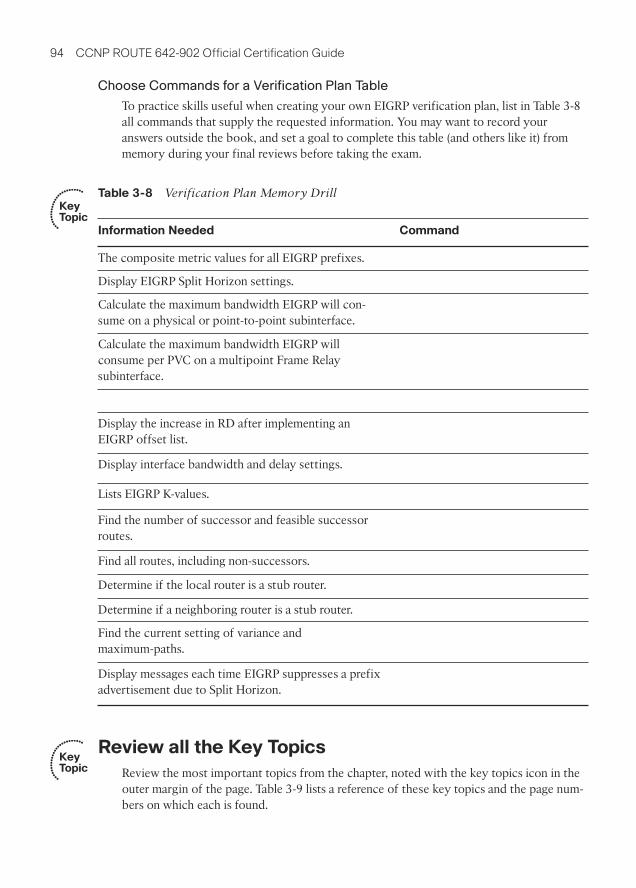
94 CCNP ROUTE 642-902 Official Certification Guide
Choose Commands for a Verification Plan Table
To practice skills useful when creating your own EIGRP verification plan, list in Table 3-8all commands that supply the requested information. You may want to record youranswers outside the book, and set a goal to complete this table (and others like it) frommemory during your final reviews before taking the exam.
Review all the Key Topics
Review the most important topics from the chapter, noted with the key topics icon in theouter margin of the page. Table 3-9 lists a reference of these key topics and the page num-bers on which each is found.
Key Topic
Table 3-8 Verification Plan Memory Drill
Information Needed Command
The composite metric values for all EIGRP prefixes.
Display EIGRP Split Horizon settings.
Calculate the maximum bandwidth EIGRP will con-sume on a physical or point-to-point subinterface.
Calculate the maximum bandwidth EIGRP will consume per PVC on a multipoint Frame Relay subinterface.
Display the increase in RD after implementing anEIGRP offset list.
Display interface bandwidth and delay settings.
Lists EIGRP K-values.
Find the number of successor and feasible successorroutes.
Find all routes, including non-successors.
Determine if the local router is a stub router.
Determine if a neighboring router is a stub router.
Find the current setting of variance and maximum-paths.
Display messages each time EIGRP suppresses a prefixadvertisement due to Split Horizon.
Key Topic

Chapter 3: EIGRP Topology, Routes, and Convergence 95
Table 3-9 Key Topics for Chapter 3
Key Topic
Element
Description Page
Number
List Three sources for seeding a local router’s EIGRP topology table 60
List EIGRP message types (5) 61
List Rules for EIGRP topology exchange 64
Definitions Feasible Distance, Reported Distance 70
Definition Feasibility Condition 79
Figure 3-8 Conceptual view of successors and feasible successors 79
List Two commands to find all EIGRP routes versus allsuccessor/feasible successor routes
80
List EIGRP process of finding routes when going active 83
Definition EIGRP stub router 85
Table 3-3 List of options on the eigrp stub command 85
Definition Rule by which summary routes reduce Query scope 86
List Rules for unequal-cost multipath 91
Complete the Tables and Lists from Memory
Print a copy of Appendix D, “Memory Tables,” (found on the CD) or at least the sectionfor this chapter, and complete the tables and lists from memory. Appendix E, “MemoryTables Answer Key,” also on the CD, includes completed tables and lists to check yourwork.
Define Key Terms
Define the following key terms from this chapter, and check your answers in the glossary.
feasibility condition, feasible distance, feasible successor, full update, partial update,reported distance, advertised distance, successor, Split Horizon, bandwidth, delay, K-value, offset list, going active, DUAL, Query scope, EIGRP stub router, unequal-costload balancing, variance

This chapter covers the following subjects:
Route Filtering: This section examines how to filter prefixesfrom being sent in EIGRP Updates or filter them from beingprocessed when received in an EIGRP Update.
Route Summarization: This section discusses the conceptsand configuration of EIGRP route summarization.
Default Routes: This section examines the benefits of usingdefault routes, and the mechanics of two methods for config-uring default routes with EIGRP.

A
ABR (area border routers), 143
interarea routes, 210–211
intra-area routes, 210–211
OSPF
route filtering, 226–230
route summarization, 232–235
virtual links, 260–262
ACK (acknowledgement) messages
EIGRP, 61, 65
LSAck messages, 200
ACL (access control lists)
EIGRP route filtering, 102–105
route maps, referencing ACL from,112
active timers, EIGRP convergenceprocess, 87
AD (Administrative Distance), routeredistribution with multiple redis-tribution points
preventing domain loops via per-routeAD settings, 350–354
preventing domain loops with AD,346–349
AD (Advertised Distance), buildingEIGRP IP routing tables, 69–72
administrative Weight (BGP PathControl), influencing, 500–501
aggregation, Internet routing,392–393
areas, 143
interarea routes
ABR, 210–211
OSPF route selection, 206–210
intra-area routes
ABR, 210–211
OSPF route selection, 205–206
OSPF database exchange process,flooding throughout an area,203–204
AS External LSA (link state advertise-ments), 180
AS_Path
AS_Path Prepend command
BGP Path Control, 517–519
increasing length via, 517–519
BGP PA, 494
Weight (BGP Path Control), influenc-ing, 508–511
AS_SEQ path attribute, BGP ASN,397–399
ASBR (Autonomous System BorderRouters)
ASBR Summary LSA (link state advertisements), 179
OSPF route summarization, 235–236
ASN (autonomous system numbers),BGP ASN
AS_SEQ path attribute, 397–399
public/private ASN, 400–402
Index

authentication
eBGP neighborships, 429–430
EIGRP
configuration checklist, 40
configuration example, 41–42
controlling EIGRP neighbor-ships, 39–43
key chain time-based logic,40–41
verification example, 42–43
OSPF, 159–161
OSPF virtual links
configuring authentication,265–267
configuring without authentica-tion, 262–264
autoconfiguration (stateless)
global unicast addressing
calculating Interface ID via EUI-64, 547–548
finding DNS IP addresses viastateless DHCP, 548–549
NDP router advertisements,546–547
IPv6 addressing, 561–562
automatic 6to4 tunneling, 627–634
auto-summary, network command andBGP route injections, 445
B
backbone routers, 143
bandwidth
EIGRP IP routing tables, configuringfor, 72–73
OSPF route selection
changing reference bandwidth,212–213
setting bandwidth, 213
WAN bandwidth control, EIGRPtopology tables, 67–69
BDR (backup designated routers), 143
BEE (Boson Exam Environment),CCNP Route exam preparation,673, 678–679
best path algorithm, BGP PathControl, 494–497
BFD (Bi-directional ForwardingDetection feature), EIGRP, 33
BGP (Border Gateway Protocol), 387
administrative control of neighborstatus, 434–435
ASN
AS_SEQ path attribute,397–399
public/private ASN, 400–402
BGP-4 (RFC 4760), 569

710 BGP (Border Gateway Protocol)
eBGP, 399–400, 419
authentication, 429–430
BGP table verification, 436–443
multihop concepts in neighbor-ships, 428
neighbor configurations, 423–424
neighborship requirements,425–426
Path Control, 498
public IP address advertisements,443–448
redundancy configuration,429–430
redundancy issues between neighbors, 426–428
verification commands for eBGP-learned routes, 441–442
EIGRP versus, 396–397
iBGP, 399–400, 419, 455
avoiding routing loops, 471–476
BGP Path Control, 498
BGP table entries, 464–468
configuring, 460–463
between Internet-connectedrouters, 459–471
next-hop reachability issues,468–471
routing loops, avoiding, 471–476
verifying, 463–464
injecting routes
network command, 443–445
route redistribution, 446–448
message type table, 436
neighborships
administrative control of neighborstatus, 434–435
clearing, 481–483
neighbor state reference table,430–431
verifying neighbors, 430–434
OSPF versus, 396–397
outbound routing to the Internet
BGP versus, 402–404
full BGP updates, 410–411
partial BGP updates, 410–411
path selection via BGP in dual-homed Internet designs,407–410
PA
AS_Path, 494
next-hop IP addresses, 494
PA table, 495
Path Control, 491
best path algorithm, 494–497
best path steps, 498
eBGP, 498
iBGP, 498
increasing AS_Path length viaAS_Path Prepend command,517–519
influencing inbound routes viaMED, 519–522
influencing outbound routes,500–519
influencing Weight, 500–513
IP routes based on best paths,513–516
maximum-paths command, 516
MED, 519–522
memorization tips for best paths,499–500
Origin PA, 498
PA, 494–500
RIB failures, 515–516

CCNP Route exams 711
public IP address assignments
network command, 443–445
route redistribution, 446–448
route filtering, 476–477
clearing neighborships, 481–483
displaying results, 483–485
filtering based on prefix/length,478–481
synchronization, iBGP routing loops,475–476
table verification
BGP update messages, 436–437
examining BGP table components,438–440
NLRI, 437
viewing BGP table subsets,440–443
verifying, 463–464
verifying neighbors, 430–434
binary-to-decimal conversion tables,702–703
branch routing, 647
broadband Internet access, 650–652
configuring DHCP servers, 664
configuring DSL, 661–663
configuring NAT, 663–664
DSL concepts, 659–661
DHCP servers/clients, 652–653
dynamic routing over GRE tunnels,658–659
floating static routes, 658
IPSec tunnels, 654–655
medium/large branches, 657–658
office security, 653–654
small branches, 656–657
VPN configuration, 667–669
broadband Internet access, branch routing, 650–652, 659–661
DHCP servers, 664
DSL, 661–663
NAT, 663–664
C
CCNP Route exams
implementation planning
focus for CCNP plans, 15
structured methodologies of, 15
styles of plans, 13–14
typical elements of, 14
planning-related exam topics
choosing commands for verifica-tion plan tables, 13
design review tables, 12
exam topics not requiring CLI,4–5
implementation plan peer reviewtables, 12
implementation plan tables, 13
preparing for, 5, 10–11
preparing for
activating practice exams, 674
BEE, 673, 678–679
chapter-ending review tools, 676
Cisco Learning Network, 675
downloading practice exams, 674
exam engine, 673, 678–679
memory tables, 675
subnetting practice, 677–678
suggested plans for finalreview/study, 676–679

712 CCNP Route exams
relating exam topics to network engineer jobs
design planning, 7
ficticious company/networkstaffing scenarios, 6–7
implementation planning, 7–10
summary of network engineer’srole, 10
verification planning, 9
updates, 705–706
verification plans
styles of plans, 13–14
typical elements of, 16
CD installation (CCNP Route exampreparation), 673–674
CEF (Cisco Express Forwarding), 366
chapter-ending review tools (CCNPRoute exam preparation), 676
Cisco Learning Network, 675
convergence
EIGRP convergence process, 32–33
active timers, 87
fast convergence to feasible suc-cessors, 78–80
feasibility conditions, 79
going active, 83–88
optimizing, 78–91
successor routes, 78–80
unequal metric route load sharing,88–91
verification of feasible successors,80–83
OSPF convergence process, 153–156
conversion tables
binary-to-decimal conversion tables,702–703
hex-to-decimal conversion tables, 701
D
DAD (Duplicate Address Detection),555
database exchanges, OSPF databaseexchange process
exchanges
DR exchanges, 200–203
exchanges without a DR, 197–198
LSA exchanges, 200
flooding throughout an area, 203–204
neighbor LSDB descriptions, describing, 198–200
neighbor state reference table, 197
OSPF message types, 196–197
periodic flooding, 204
Dead timers, OSPF neighborships,153–156
decimals
binary-to-decimal conversion tables,702–703
hex-to-decimal conversion tables, 701
default keywords, PBR logic ordering,370–371
default routing
EIGRP default routing
advertising static default routes,127–128
configuring default networks,128–131
Internet routers, 126–127
OSPF default routing, 221, 236–239
default-information originate command,OSPF default routing, 237–239
delays, configuring for EIGRP IP routingtables, 72–73
design planning (CCNP Route exams), 7
design review tables (CCNP Routeexams), 12

EIGRP (Enhanced Interior Gateway Routing Protocol) 713
DHCP (Dynamic Host ConfigurationProtocol)
branch routing, 652–653, 664
stateful DHCP, global unicast addressing, 545
stateless autoconfiguration, 548–549
distributed lists, OSPF route filtering,230–231
distribute-list command, route redistribution filtering, 343
DMVPN (Dynamic Multipoint VirtualPrivate Networks), 664
DNA (Do Not Age) bits (LSA), 262
DNS IP addresses, finding via statelessDHCP, 548–549
DR (designated routers), 143
Network LSA, 186–191
OSPF
database exchanges, 200–203
database exchanges without,197–198
OSPF over multipoint FrameRelay, 271–272
DSL (Digital Subscriber Lines), branchrouter configuration for broadbandaccess, 659–663
dual stacks (IPv4/IPv6), 611–612
dual-homed Internet design, outboundrouting to the Internet
full BGP updates, 410–411
partial BGP updates, 410–411
path selection via BGP, 407–410
preferred path routing, 405–407
dual-multihomed Internet design, outbound routing to the Internet,412–413
dynamic multipoint tunneling, 626
automatic 6to4 tunnels, 627–634
ISATAP tunneling, 634–639
dynamic routing, branch routing,658–659
E
eBGP (external BGP), 399–400, 419
BGP Path Control, 498
BGP table verification, 436
neighborships
authentication, 429–430
multihop concepts, 428
neighbor configurations, 423–424
redundancy configuration,429–430
redundancy issues between neighbors, 426–428
requirements for forming,425–426
public IP address assignments
network command, 443–445
route redistribution, 446–448
verification commands for eBGP-learned routes, 441–442
EIGRP (Enhanced Interior GatewayRouting Protocol), 19, 569
ACK messages, 61, 65
authentication
configuration checklist, 40
configuration example, 41–42
controlling EIGRP neighborships,39–43
key chain time-based logic, 40–41
verification example, 42–43
BFD feature, 33
BGP versus, 396–397
CCNA review
calculating best routes for routingtables, 30

714 EIGRP (Enhanced Interior Gateway Routing Protocol)
configuration review, 23–25
exchanging topology information,29–30
internals review, 29
verification review, 25–29
convergence process, 32–33
active timers, 87
fast convergence to feasible successors, 78–80
feasibility conditions, 79
going active, 83–88
optimizing, 78–91
successor routes, 78–80
unequal metric route load sharing,88–91
verification of feasible successors,80–83
default routing
advertising static default routes,127–128
configuring default networks,128–131
Internet routers, 126–127
EIGRP for IPv4 comparisons, 581–582
EIGRP for IPv6
configuring, 582–584
EIGRP for IPv4 comparisons,581–582
verifying, 584–587
feature summary table, 31
IP routing tables, building
calculating FD/RD metrics, 69–72
configuring bandwidth, 72–75
configuring delays, 72–73
configuring k-values, 75–76
metric tuning, 72–78
Offset Lists, 76–78
neighborships
configuration settings that pre-vent relationships, 46–48
configuring Hello/Hold timers,33–34
configuring metric componentsvia k-values, 47–48
controlling via EIGRP authentica-tion, 39–43
controlling via static configura-tions, 43–45
Frame Relay, 49
manipulating Hello/Hold timers,32–33
MetroE, 51
MPLS VPN, 50
neighbor requirements, 46,152–153
neighborships over WAN, 48–51
passive interface feature, 36–39
verifying Hello/Hold timers,34–36
RID, 48
route filtering, 101
ACL references, 102–105
IP prefix list references, 105–110
route maps, 110–114
route redistribution
baseline configuration examples,298–299
configuring with default metriccomponents, 300–302
default AD defeats loop fromEIGRP to OSPF to EIGRP,346–347
default AD defeats loop fromOSPF to EIGRP to OSPF,346–347
redistribute command reference,297–298
verifying redistribution, 302–305

External Attributes LSA (link state advertisements) 715
route summarization
auto-summary, 124–126
benefits/trade-offs, 120
calculating summary routes, 116
choosing where to summarizeroutes, 116–117
configuring, 120–124
influencing summary route selection, 117–118
suboptimal forwarding, 118–120
summary route design, 114–115
topology tables, building
contents of update messages,61–64
seeding topology tables, 60
Split Horizon, 64
Split Horizon defaults on FrameRelay multipoint subinterfaces,65–67
update process, 64–65
WAN bandwidth control, 67–69
WAN issues for topologyexchanges, 65–69
updates
update messages, 30, 61–64
update process, 64–65
Ethernet, MetroE (MetropolitanEthernet)
EIGRP neighborships, 51
OSPF neighborships, 167–169
EUI-64, Interface ID calculation forglobal unicast addresses, 547–548
exam engine (CCNP Route exam preparation), 673, 678–679
exams (CCNP Route)
implementation planning
focus for CCNP plans, 15
structured methodologies of, 15
styles of plans, 13–14
typical elements of, 14
planning-related exam topics
choosing commands for verifica-tion plan tables, 13
design review tables, 12
exam topics not requiring CLI,4–5
implementation plan peer reviewtables, 12
implementation plan tables, 13
preparing for, 5, 10–11
preparing for
activating practice exams, 674
BEE, 673, 678–679
chapter-ending review tools, 675
Cisco Learning Network, 675
downloading practice exams, 674
exam engine, 673, 678–679
memory tables, 675
subnetting practice, 677–678
suggested plans for finalreview/study, 675–677
relating exam topics to network engineer jobs
design planning, 7
ficticious company/networkstaffing scenarios, 6–7
implementation planning, 7–10
summary of network engineer’srole, 10
verification planning, 9
updates, 705–706
verification plans
styles of plans, 13–14
typical elements of, 16
explicit acknowledgements. See LSAck(Link State Acknowledgement) messages
External Attributes LSA (link stateadvertisements), 180

716 FD (Feasible Distance), building EIGRP IP routing tables
F
FD (Feasible Distance), building EIGRPIP routing tables, 69–72
feasibility conditions, EIGRP conver-gence process, 79
feasible successors, verifying (EIGRPconvergence process), 78–80
final review/study, suggested plans for,676–679
floating static routes, branch routing,658
flooding process, OSPF databaseexchange process, 203–204
Frame Relay
EIGRP
neighborships, 49
topology tables, building, 65–67
IP subnetting design over Frame Relay,267–268
OSPF neighborships, Frame Relaypoint-to-point subinterfaces, 166
OSPF over multipoint Frame Relay
configuring operations, 274–282
configuring using multipointsubinterfaces, 269–270
configuring using physical inter-faces, 268–269
DR, 271–272
IP subnetting design over FrameRelay, 267–268
mapping issues with partial meshtopologies, 272–273
NBMA, 275–279
neighbor discovery, 270–271
network type point-to-multipoint,279–281
static neighbor definition,270–271
verifying operations, 274–282
G
GET VPN (Group Encrypted TransportVirtual Private Networks), 665
global unicast addressing, 533
assigning, 544
stateful DHCP, 545
stateful IPv6 address configura-tion, 549
stateless autoconfiguration,545–549
automatic 6to4 tunnels, 632–634
global route aggregation, 534–536
prefix assignment example, 539–541
subnetting, 541–543
going active, EIGRP convergenceprocess, 83
SIA routes, 87–88
stub router impact on Query Scope,84–86
summary route impact on Query Scope,86–87
GRE (Generic Route Encapsulation) tunneling, 619–620, 624–625
dynamic routing over GRE tunnels,branch routing, 658–659
VPN, configuring in, 666–667
Group Membership LSA (link stateadvertisements), 180
H
Hello messages, OSPF, 152
Hello timers
EIGRP
configuring in, 33–34
manipulating in, 32–33
verifying in, 34–36

Internet routing 717
OSPF neighborships, optimizing convergence via Hello timers,153–156
hex-to-decimal conversion tables, 701
Hold timers, EIGRP
configuring in, 33–34
manipulating in, 32–33
verifying in, 34–36
I
iBGP (internal BGP), 399–400, 419, 455
BGP Path Control, 498
BGP table entries, 464–468
configuring, 460–463
between Internet-connected routers,459–471
next-hop reachability issues, 468
changing next-hop addresses vianext-hop-self command,469–471
recursive route table lookups, 469
routing loops, avoiding, 471
BGP synchronization, 475–476
iBGP mesh topologies, 472–475
IGP redistribution, 475–476
verifying, 463–464
IGP (Interior Gateway Protocol) redistri-bution
advanced IGP redistribution, 329
multiple redistribution points,344–357
route maps, 332–343
basic IGP redistribution, 289
EIGRP route redistribution,297–305
need for route redistribution,292–294
OSPF route redistribution,305–323
redistribution concepts, 294–297
redistribution processes, 294–297
iBGP routing loops, avoiding, 475–476
IPv6 addressing, 595
redistributing with route maps,598–599
redistributing without routemaps, 596–598
implementation planning (CCNP Routeexams), 7–9
documenting, 10
focus for CCNP plans, 15
implementation plan tables, 13
peer review tables, 12
structured methodologies of, 15
styles of plans, 13–14
typical elements of, 14
interarea routes
ABR (area border routers), 210–211
OSPF route selection, 206–210
internal routers, 143
Internet routing, 387, 390
aggregation, 392–393
EIGRP default routing, 126–127
NAT, 393
outbound routing to the Internet
BGP versus default routing,402–404
dual-homed Internet design,405–411
dual-multihomed Internet design,412–413
single-homed Internet design,404–405
single-multihomed Internetdesign, 411–412
PAT, 393–394

718 Internet routing
private IP address assignments,394–395
public IP address assignments, 391–392
intra-area routes
ABR, 210–211
OSPF route selection, 205–206
IP addresses, Internet routing
private IP address assignments,394–395
public IP address assignments, 391–392
IP MTU (maximum transmission unit)mismatches, OSPF neighborships,157–159
IP prefix lists
concepts of, 105–107
EIGRP route filtering, 105–110
matching, samples of, 107–108
route maps, referencing prefix lists from,112
IP routing tables, building EIGRP IProuting tables
calculating FD/RD metrics, 69–72
configuring
bandwidth, 72–75
delays, 72–73
k-values, 75–76
metric tuning, 72–78
Offset Lists, 76–78
IP SLA (Service Level Agreements), 363
concepts of, 373–374
configuring, 374–376
PBR, 372, 381
tracking IP SLA operations to influencerouting
configuring PBR to track IP SLA,381
static routes, 378–381
verifying, 376–377
IP subnetting design over Frame Relay,267–268
IPSec tunnels, branch routing, 654–655
IPsec VPN (IP security virtual privatenetworks), configuring, 665–666
IPv4 addresses
EIGRP for IPv4, 581–582
IPv6 coexistence with, 607
dual stacks, 611–612
NAT Protocol Translation,617–619
tunneling, 612–617
IPv6 addressing, 529, 532
connected neighbors, 560
connected routes, 560
DAD, 555
EIGRP for IPv6
configuring, 582–584
EIGRP for IPv4 comparisons,581–582
verifying, 584–587
global unicast addressing, 533
assigning, 544–549
global route aggregation, 534–536
prefix assignment example,539–541
stateful DHCP, 545
stateful IPv6 address configura-tion, 549
stateless autoconfiguration,545–549
subnetting, 541–543
IGP redistribution, 595
redistributing with route maps,598–599
redistributing without routemaps, 596–598

LSA (link state advertisements) 719
inverse neighbor discovery, 555–556
IPv4 coexistence with, 607
dual stacks, 611–612
NAT Protocol Translation,617–619
tunneling, 612–617
Layer 2 mapping, neighbor address protocol, 554–555
multicast groups joined by IPv6 routerinterfaces, 559–560
multicast IPv6 addressing, 553–554
neighbor tables, 561
OSPFv3
configuring, 590–592
OSPFv2 comparisons, 588–589
verifying, 592–595
overview of, 550
prefixes
conventions for writing, 537–539
terminology, 543–544
representing IPv6 addresses, conven-tions for, 536–537
RIPng, 573
configuring, 575–578
RIP-2 comparisons, 574
verifying, 578–580
router configurations, 556–559
routing protocol updates, 573
stateless autoconfiguration, 561–562
static IPv6 addresses, router configura-tions, 557–559
static IPv6 routes, 599–601
tunneling
general concepts, 612–614
GRE tunneling, 619–620, 624–625
MCT, 619–624
point-to-multipoint tunnels,615–616, 626–640
point-to-point tunnels, 614–615
static point-to-point tunnels,619–626
tunneling comparison table, 617
unicast IPv6 addressing, 550, 553
link local unicast addresses,551–552
unique local addresses, 551
ISATAP (Intra-Site Automatic TunnelAddressing Protocol) tunneling,634–639
J - K - L
key chain time-based logic, EIGRPauthentication, 40–41
k-values, configuring EIGRP metric components, 47–48, 75–76
LAN (local area networks), OSPF neighborships
neighbor discovery, enabling,150–152
LAN adjacencies, 149–161
large branches (branch routing),657–658
Layer 2 address mapping, neighboraddress protocol, 554–555
link local unicast addresses, 551–552
load balancing, EIGRP convergenceprocess, 88–91
Local_Pref, influencing Weight (BGPPath Control), 507–508
Local_Pref Internetwork example,508–511
route maps, 511–513
LSA (link state advertisements), 143
ASBR Summary LSA, 179
720 LSA (link state advertisements)
DNA bits, 262
External Attributes LSA, 180
AS External LSA, 180
Group Membership LSA, 180
Net Summary LSA, 179
Network LSA, 179, 196
concepts of, 187
DR, 186
show commands, 187–191
NSSA External LSA, 180
Opaque LSA, 180
OSPF
database exchange process, 200
route filtering, 226–230
route redistribution, 311–318
OSPF LSDB, 179
limiting number of LSA, 195
Network LSA, 186–191
Router LSA, 180–186
Summary LSA, 191–195
Router LSA, 179–186, 195
Summary LSA, 191–196
LSAck (Link State Acknowledgement)messages, 200
LSDB (link state databases), OSPFLSDB, 140–142
LSA types, 179–180
neighbor LSDB descriptions, discovering, 198–200
Network LSA, 186–191
number of LSA, limiting, 195
Router LSA, 180–186
Summary LSA, 191–195
LSID (link state identifers), 180
LSR (Link State Request) messages, 200
LSU (Link State Updates), 142, 200
M
maximum-paths command, BGP PathControl, 516
MCT (manually configured tunnels), 619
configuring, 620–623
verifying, 623–624
MED (Multi-Exit Discriminators)
concepts of, 519–520
configuring, 521–522
features of, 521
medium/large branches (branch routing),657–658
memory tables, CCNP Route exampreparation, 675
MetroE (Metropolitan Ethernet)
EIGRP neighborships, 51
OSPF neighborships, 167–169
MPLS VPN (Multiprotocol LabelSwitching Virtual Private Networks)
EIGRP neighborships, 50
OSPF neighborships, 166–167
MTU (maximum transmission units) mis-matches, OSPF neighborships,157–159
multicast IPv6 addressing, 553–554
multipoint Frame Relay, OSPF over
configuring
operations, 274–282
via multipoint subinterfaces,269–270
via physical interfaces, 268–269
DR, 271–272
IP subnetting design over Frame Relay,267–268
mapping issues with partial meshtopologies, 272–273
NBMA, 275–279

network engineer jobs, relating CCNP Route exam topics to 721
neighbor discovery, 270–271
network type point-to-multipoint,279–281
network type point-to-multipoint nonbroadcast, 281–282
static neighbor definition, 270–271
verifying operations, 274–282
N
N (BGP best path memorization tip),500
NAT (network address translation)
branch router configuration for broad-band access, 663–664
Internet routing, 393
NAT Protocol Translation, 617–619
NBMA (Network Type Nonbroadcast),OSPF over multipoint Frame Relay,275–279
NDP router advertisements, statelessautoconfiguration of global unicastaddresses, 546–547
neighbor address protocol, Layer 2address mapping, 554–555
neighbor tables, IPv6 addressing, 561
neighbor weight command, influencingWeight (BGP Path Control), 506–507
neighborships
EIGRP neighborships
configuration settings that prevent relationships, 46–48
configuring Hello/Hold timers,33–34
configuring metric componentsvia k-values, 47–48
controlling via EIGRP authentica-tion, 39–43
controlling via static configura-tions, 43–45
Frame Relay, 49
manipulating Hello/Hold timers,32
MetroE, 51
MPLS VPN, 50
neighbor requirements, 46,152–153
neighborships over WAN, 48–51
passive interface feature, 36–39
verifying Hello/Hold timers,34–36
OSPF neighborships
authentication, 159–161
enabling neighbor discovery onLAN, 150–152
Frame Relay point-to-point subinterfaces, 166
LAN adjacencies, 149–161
MetroE, 167–169
MPLS VPN, 166–167
MTU mismatches, 157–159
neighbor requirements, 46,152–153
network types, 162–163
optimizing convergence viaHello/Dead timers, 153–156
point-to-point links, 164–166
unique RID, 156–157
WAN adjacencies, 162–169
Net Summary LSA (link state advertise-ments), 179
network command, BGP route injec-tions, 443–445
network engineer jobs, relating CCNPRoute exam topics to
design planning, 7

722 network engineer jobs, relating CCNP Route exam topics to
ficticious company/network staffingscenarios, 6–7
implementation planning, 7–10
summary of network engineer’s role, 10
verification planning, 9
Network LSA (link state advertisements),179, 196
concepts of, 187
OSPF LSDB, DR, 186
show commands, 187–191
network type point-to-multipoint, OSPFover multipoint Frame Relay,279–281
network type point-to-multipoint non-broadcast, OSPF over multipointFrame Relay, 281–282
next-hop IP addresses, BGP PA, 494
next-hop-self command, iBGP next-hopreachability issues, 469–471
NLRI (Network Layer ReachabilityInformation), BGP table verification,437
NSSA (not-so stubby areas), 240–241,248–250
NSSA External LSA (link state adver-tisements), 180
OSPF route redistribution, externalroutes in NSSA areas, 320–323
totally NSSA, 240–241
O
office security, branch routing, 653–654
Offset Lists, building EIGRP IP routingtables, 76–78
OMNI (BGP best path memorizationtip), 500
Opaque LSA (link state advertisements),180
Origin PA (Path Attributes), BGP PA,498
OSPF (Open Shortest Path First), 137,569
authentication, 159–161
BGP versus, 396–397
commonly used terms table, 142–143
configuration review, 144–146
convergence, optimizing via Hello/Deadtimers, 153–156
database exchange process
discovering neighbor LSDBdescriptions, 198–200
exchanges without a DR, 197–198
exchanging LSA, 200
exchanging with DR, 200–203
flooding throughout an area,203–204
neighbor state reference table, 197
OSPF message types, 196–197
periodic flooding, 204
default routing, 221, 236–239
feature summary table, 149
Hello messages, 152
LSDB, 140–142
limiting number of LSA, 195
LSA types, 179–180
Network LSA, 186–191
Router LSA, 180–186
Summary LSA, 191–195
multipoint Frame Relay
configuring operations, 274–282
configuring using multipointsubinterfaces, 269–270
configuring using physical inter-faces, 268–269
DR, 271–272
IP subnetting design over FrameRelay, 267–268

OSPF (Open Shortest Path First) 723
mapping issues with partial meshtopologies, 272–273
NBMA, 275–279
neighbor discovery, 270–271
network type point-to-multipoint,279–281
network type point-to-multipointnonbroadcast, 281–282
static neighbor definition,270–271
verifying operations, 274–282
neighborships
authentication, 159–161
enabling neighbor discovery onLAN, 150–152
Frame Relay point-to-point subin-terfaces, 166
LAN adjacencies, 149–161
MetroE, 167–169
MPLS VPN, 166–167
MTU mismatches, 157–159
neighbor requirements, 46,152–153
network types, 162–163
optimizing convergence viaHello/Dead timers, 153–156
point-to-point links, 164–166
unique RID, 156–157
WAN adjacencies, 162–169
network types, 274
OSPFv3
configuring, 590–592
OSPFv2 comparisons, 588–589
verifying, 592–595
route filtering, 221, 225
filtering OSPF routes added torouting tables, 230–231
filtering with distributed lists,230–231
Type 3 LSA filtering, 226–230
route redistribution
configuring with minimal parame-ters, 306–310
default AD defeats loop fromEIGRP to OSPF to EIGRP,347–348
default AD defeats loop fromOSPF to EIGRP to OSPF,347–348
E1/E2 route comparisons,319–320
external routes in NSSA areas,320–323
external type 2 route LSA,311–318
external type 2 route metrics,311–318
redistribute command reference,305–306
redistributing into OSPF as E1routes, 318–319
setting OSPF metrics, 310–311
route selection, 204
calculating interarea route costs,206–210
calculating intra-area route costs,205–206
changing reference bandwidth,212–213
configuring cost directly, 213
metric calculation for internalroutes, 205–211
metric calculations, 211–212
metric tuning, 212–214
setting bandwidth, 213
special rules for interarea routes,210–211
special rules for intra-area routes,210–211
SPF calculations, 211–212
verifying cost settings, 213–214

724 OSPF (Open Shortest Path First)
route summarization, 221, 231
manual summarization at ABR,232–235
manual summarization at ASBR,235–236
stub routers, 221, 239
stubby areas, 239
configuring, 241–243
NSSA, 240–241, 248–250
summary table, 250
totally NSSA, 240–241
totally stubby areas, 240–241,246–248
types of, 240–241
verifying, 243–246
verification review, 146–148
virtual links
concepts of, 260–262
configuring authentication,265–267
configuring without authentica-tion, 262–264
verifying, 264–265
P
partial mesh topologies, OSPF over mul-tipoint Frame Relay mapping issues,272–273
passive interface feature, EIGRP neigh-borships, 36–39
PAT (port address translation), Internetrouting, 393–394
PBR (Policy-Based Routing), 363, 366
configuring, 368–370
default keyword and logic ordering,370–371
IP precedence, setting, 371–372
IP SLA, 372, 381
locally created packets, applying PBRto, 371
matching packets, 367–368
setting routes, 367–368
periodic flooding, OSPF databaseexchange process, 204
planning-related exam topics (CCNPRoute exams)
choosing commands for verificationplan tables, 13
design review tables, 12
exam topics not requiring CLI, 4–5
implementation plan peer review tables,12
implementation plan tables, 13
preparing for, 5, 10–11
point-to-multipoint tunneling, 615–616,626
automatic 6to4 tunnels, 627–634
ISATAP tunneling, 634–639
point-to-point links, OSPF neighbor-ships, 164–166
point-to-point tunneling, 614–615
GRE tunneling, 619–620, 624–625
MCT, 619–624
practice exams (CCNP Route exams),downloading, 674
prefix lists
concepts of, 105–107
EIGRP route filtering, 105–110
matching, samples of, 107–108
route maps, referencing prefix lists from,112
preparing for CCNP Route Exams
activating practice exams, 674
BEE, 673, 678–679
chapter-ending review tools, 675
Cisco Learning Network, 675

route maps 725
downloading practice exams, 674
exam engine, 673, 678–679
memory tables, 675
subnetting practice, 677–678
suggested plans for final review/study,675–677
PVC (permanent virtual circuits), EIGRPneighborships on Frame Relay, 49
Q - R
QoS (Quality of Service), PBR, 371–372
Query Scope, EIGRP convergenceprocess
stub router impact on Query Scope,84–86
summary route impact on Query Scope,86–87
RD (Reported Distance), building EIGRPIP routing tables, 69–72
recursive route table lookups, iBGP next-hop reachability issues, 469
redistribute command reference
EIGRP route redistribution, 297–298
OSPF route redistribution, 305–306
reference bandwidth, OSPF route selec-tion, 212–213
review tools (chapter-ending), 676
reviews (final), suggested plans for,676–679
RIB failures, BGP Path Control,515–516
RID (Router ID)
EIGRP RID, 48
OSPF neighborships, unique RID,156–157
RIP-2 (Routing Information Protocol-2),RIPng comparisons, 574
RIPng (Routing Information Protocolnext generation), 569, 573
configuring, 575–578
RIP-2 comparisons, 574
verifying, 578–580
route filtering
BGP route filtering, 476–477
clearing neighborships, 481–483
displaying results, 483–485
filtering based on prefix/length,478–481
EIGRP route filtering, 101
ACL references, 102–105
IP prefix list references, 105–110
route maps, 110–114
OSPF route filtering, 221, 225
filtering OSPF routes added torouting tables, 230–231
filtering with distributed lists,230–231
Type 3 LSA filtering, 226–230
route maps
ACL references, 112
concepts of, 111–112
EIGRP route filtering, 110–114
IGP redistribution in IPv6 addressing
redistributing with route maps,598–599
redistributing without routemaps, 596–598
prefix list references, 112
route redistribution, 332–333
configuring metric settings,339–341
filtering redistributed routes,334–339

726 route maps
redistribution filtering via distrib-ute-list command, 343
verifying metric settings, 341–342
Weight (BGP Path Control), influencing,504–506, 511–513
route redistribution
advanced IGP redistribution, 329
multiple redistribution points,344–357
route maps, 332–343
basic IGP redistribution, 289
EIGRP route redistribution,297–305
need for route redistribution,292–294
OSPF route redistribution,305–323
redistribution concepts, 294–297
redistribution processes, 294–297
BGP route injections, 446–448
EIGRP route redistribution
baseline configuration examples,298–299
configuring with default metriccomponents, 300–302
redistribute command reference,297–298
verifying redistribution, 302–305
multiple redistribution points, 344
domain loop problems with multi-ple routing domains, 349–357
preventing domain loops via per-route AD settings, 350–354
preventing domain loops viaroute-tag filtering using distrib-ute lists, 355–357
preventing domain loops via sub-net filtering while redistribut-ing, 354–355
preventing domain loops withAD, 346–349
preventing routing domain loopswith higher metrics, 345
OSPF route redistribution
configuring with minimal parame-ters, 306–310
E1/E2 route comparisons,319–320
external routes in NSSA areas,320–323
external type 2 route LSA,311–318
external type 2 route metrics,311–318
redistribute command reference,305–306
redistributing into OSPF as E1routes, 318–319
setting OSPF metrics, 310–311
route maps, 332–334
configuring metric settings,339–341
filtering redistributed routes,334–339
redistribution filtering via distrib-ute-list command, 343
verifying metric settings, 341–342
route summarization
EIGRP route summarization
auto-summary, 124–126
benefits/trade-offs, 120
calculating summary routes, 116
choosing where to summarizeroutes, 116–117
configuring, 120–124
influencing summary route selec-tion, 117–118

static point-to-point tunnels 727
suboptimal forwarding, 118–120
summary route design, 114–115
OSPF route summarization, 221, 231
manual summarization at ABR,232–235
manual summarization at ASBR,235–236
Router LSA (link state advertisements),179–186, 195
routing loops
iBGP routing loops, avoiding, 471
BGP synchronization, 475–476
iBGP mesh topologies, 472–475
IGP redistribution, 475–476
route redistribution with multiple redis-tribution points
domain loop problems with multi-ple routing domains, 349–357
preventing domain loops via per-route AD settings, 350–354
preventing domain loops viaroute-tag filtering using distribute lists, 355–357
preventing domain loops via subnet filtering while redistributing, 354–355
preventing domain loops withAD, 346–349
preventing routing domain loopswith higher metrics, 345
routing tables, OSPF route filtering,230–231
RTP (Reliable Transport Protocol),EIGRP updates, 30, 65
S
security, branch routing, 653–654
show commands, Network LSA (linkstate advertisements), 187–191
SIA (Stuck-In-Active) routes, EIGRPconvergence process, 87–88
Simulation mode (BEE), 678
single-homed Internet design, outboundrouting to the Internet, 404–405
single-multihomed Internet design, out-bound routing to the Internet,411–412
small branches (branch routing),656–657
SPF (shortest path first), OSPF, 142,211–212
Split Horizon, building EIGRP topologytables, 64–67
stateful DHCP (Dynamic HostConfiguration Protocol), global uni-cast addressing, 545
stateless autoconfiguration
global unicast addressing
calculating Interface ID via EUI-64, 547–548
finding DNS IP addresses viastateless DHCP, 548–549
NDP router advertisements,546–547
IPv6 addressing, 561–562
stateless DHCP (Dynamic HostConfiguration Protocol), finding DNSIP addresses via stateless DHCP,548–549
static configurations, EIGRP neighbor-ships, 43–45
static default routes, EIGRP default rout-ing, 127–128
static IPv6 addresses, router configura-tions, 557–559
static point-to-point tunnels, 619
GRE tunneling, 619–620, 624–625
MCT, 619
configuring, 620–623
verifying, 623–624

728 static routes
static routes
floating static routes, branch routing,658
IP SLA, tracking operations to influencerouting, 378–381
static default routes, EIGRP defaultrouting, 127–128
static IPv6 routes, 599–601
stub routers
EIGRP convergence process, stub routerimpact on Query Scope, 84–86
OSPF, 221, 239
stubby areas
NSSA, 240–241, 248–250
OSPF stubby areas, 239
configuring, 241–243
summary table, 250
totally stubby areas, 246–248
types of, 240–241
verifying, 243–246
totally NSSA, 240–241
totally stubby areas, 240–241
Study mode (BEE), 678
subnetting
global unicast addressing, 541–543
practicing, 677–678
successor routes, EIGRP convergenceprocess, 78–80
Summary LSA (link state advertise-ments), 191–196
summary routes
EIGRP convergence process, summaryroute impact on Query Scope,86–87
EIGRP route summarization
auto-summary, 124–126
benefits/trade-offs, 120
calculating summary routes, 116
choosing where to summarizeroutes, 116–117
configuring, 120–124
influencing summary route selec-tion, 117–118
suboptimal forwarding, 118–120
summary route design, 114–115
OSPF route summarization, 221, 231
manual summarization at ABR,232–235
manual summarization at ASBR,235–236
synchronization (BGP), iBGP routingloops, 475–476
T
tables
binary-to-decimal conversion tables,702–703
conversion tables, 701–703
design review tables (CCNP Routeexams), 12
EIGRP IP routing tables, building,69–78
bandwidth, 72–75
calculating FD/RD metrics, 69–72
configuring, 72–76
delays, 72–73
k-values, 75–76
metric tuning, 72–78
Offset Lists, 76–78
feature summary table (OSPF), 149
hex-to-decimal conversion tables, 701
implementation plan tables, 13
memory tables, CCNP Route exampreparation, 675
neighbor tables, IPv6 addressing, 561

verifying 729
peer review tables, 12
summary tables (stubby areas), 250
topology tables, building
contents of update messages,61–64
seeding topology tables, 60
Split Horizon, 64
Split Horizon defaults on FrameRelay multipoint subinterfaces,65–67
update process, 64–65
WAN bandwidth control, 67–69
WAN issues for topologyexchanges, 65–69
tunneling comparison table, 617
verification plan tables, choosing com-mands for, 13
tests. See CCNP Route exams
topology tables
EIGRP topology tables, building
contents of update messages,61–64
seeding topology tables, 60
Split Horizon defaults on FrameRelay multipoint subinterfaces,65–67
update process, 64–65
WAN bandwidth control, 67–69
WAN issues for topologyexchanges, 65–69
totally NSSA (not-so stubby areas),240–241
totally stubby areas, 240–241, 246–248
tunneling
general concepts, 612–614
GRE tunnels, configuring in VPN,666–667
IPSec tunnels, branch routing, 654–655
point-to-multipoint tunnels, 615–616,626–640
point-to-point tunnels, 614–615
GRE tunneling, 619–620,624–625, 658–659
MCT, 619–624
static point-to-point tunnels,619–626
tunneling comparison table, 617
virtual tunnel interfaces, 664
U
unicast IPv6 addressing, 550, 553
link local unicast addresses, 551–552
unique local addresses, 551
unique local IPv6 addresses, 551
updates
BGP updates
outbound routing to the Internet,410–411
update messages, table verifica-tion, 436–437
CCNP Route exams, 705–706
EIGRP
update messages, 30, 61–64
update process, 64–65
IPv6 addressing, routing protocolupdates, 573
LSU, 200
outbound routing to the Internet, fullBGP updates, 410–411
V
verifying
EIGRP for IPv6, 584–587
feasible successors (EIGRP convergenceprocess), 78–80

730 verifying
Hello/Hold timers, 34–36
iBGP, 463–464
verifying neighbors, 430–434
IP SLA, 376–377
MCT, 623–624
OSPF
OSPF over multipoint FrameRelay operations, 274–282
OSPFv3, 592–595
Path Control, 430–434, 463–464
RIPng, 578–580
route redistribution
EIGRP, 302–305
metric settings, 341–342
route selection, verifying cost settings,213–214
stubby areas, 243–246
verification planning (CCNP Routeexams), 9
styles of plans, 13–14
typical elements of, 16
verification plan tables, choosingcommands for, 13
virtual links, 264–265
virtual links (OSPF)
concepts of, 260–262
configuring
authentication, 265–267
without authentication, 262–264
verifying, 264–265
virtual tunnel interfaces, 664
VPN (virtual private networks)
branch routing, 667–669
DMVPN, 664
GET VPN, 665
GRE tunnels, configuring, 666–667
IPsec VPN, configuring, 665–666
virtual tunnel interfaces, 664
W - X - Y - Z
WAN (wide area networks)
EIGRP
IP routing tables, building, 73–75
neighborships, 48–51
topology tables, building, 65–69
OSPF neighborships, WAN adjacencies,162–169
Weight (BGP Path Control), influencing
administrative Weight, 500–501,504–506
AS_Path length Internetwork example,508–511
local preferences, setting, 507–508
Local_Pref Internetwork example,508–511
route maps, 511–513
sample Internetworks, 501–504
setting via
neighbor weight command,506–507
route maps, 504–506
WLLA (BGP best path memorizationtip), 500