CCNA Exploration Network Fundamentals - … networks/Chapter9...The first LAN in the world was the...
51
Updated: 07/07/2008 1 CCNA Exploration Network Fundamentals Chapter 09 Ethernet
Transcript of CCNA Exploration Network Fundamentals - … networks/Chapter9...The first LAN in the world was the...

Updated: 07/07/20081
CCNA Exploration
Network Fundamentals
Chapter 09
Ethernet

2
9.0.1 Introduction

3
9.0.1 Introduction
Internet Engineering Task Force (IETF) maintains the functional
protocols and services for the TCP/IP protocol suite in the upper
layers. However, the functional protocols and services at the OSI
Data Link layer and Physical layer are described by various
engineering organizations (IEEE, ANSI, ITU) or by private
companies (proprietary protocols).
Ethernet is comprised of standards at these lower layers, it may best
be understood in reference to the OSI model. The OSI model
separates the Data Link layer functionalities of addressing, framing
and accessing the media from the Physical layer standards of the
media. Ethernet standards define both the Layer 2 protocols and the
Layer 1 technologies. Although Ethernet specifications support
different media, bandwidths, and other Layer 1 and 2 variations, the
basic frame format and address scheme is the same for all varieties
of Ethernet.
Ethernet has evolved from a shared media, contention-based data
communications technology to today's high bandwidth, full-duplex
technology.

4
9.1 Overview of Ethernet
9.1.1 Ethernet – Standards and Implementation
IEEE Standards
The first LAN in the world was the original version of Ethernet. Robert
Metcalfe and his coworkers at Xerox designed it more than thirty years
ago. The first Ethernet standard was published in 1980 by a consortium
of Digital Equipment Corporation, Intel, and Xerox (DIX). Metcalfe
wanted Ethernet to be a shared standard from which everyone could
benefit, and therefore it was released as an open standard. The first
products that were developed from the Ethernet standard were sold in
the early 1980s.

5
9.1.2 Ethernet – Layer 1 and 2

6
9.1.3 Logical Link Control –
Connecting to the Upper Layers

7
9.1.3 Logical Link Control – Connecting to the
Upper Layers LLC is implemented in software, and its implementation is independent
of the physical equipment. In a computer, the LLC can be considered
the driver software for the Network Interface Card (NIC). The NIC driver
is a program that interacts directly with the hardware on the NIC to pass
the data between the media and the Media Access Control sublayer.
9.1.4 MAC – Getting Data to the Media

8
9.1.4 MAC – Getting Data to the Media
Logical Topology
The underlying logical topology of Ethernet is a multi-
access bus. This means that all the nodes (devices) in
that network segment share the medium. This further
means that all the nodes in that segment receive all the
frames transmitted by any node on that segment.
Because all the nodes receive all the frames, each node
needs to determine if a frame is to be accepted and
processed by that node. This requires examining the
addressing in the frame provided by the MAC address.
Ethernet provides a method for determining how the
nodes share access to the media. The media access
control method for classic Ethernet is Carrier Sense
Multiple Access with Collision Detection (CSMA/CD).

9
9.1.5 Physical Implementations of Ethernet
Most of the traffic on the Internet originates and ends with
Ethernet connections. Since its inception in the 1970s, Ethernet
has evolved to meet the increased demand for high-speed
LANs. When optical fiber media was introduced, Ethernet
adapted to this new technology to take advantage of the
superior bandwidth and low error rate that fiber offers. Today,
the same protocol that transported data at 3 Mbps can carry
data at 10 Gbps.
The success of Ethernet is due to the following factors:
Simplicity and ease of maintenance
Ability to incorporate new technologies
Reliability
Low cost of installation and upgrade
The introduction of Gigabit Ethernet has extended the original
LAN technology to distances that make Ethernet a Metropolitan
Area Network (MAN) and WAN standard.

10
9.1.5 Physical Implementations of Ethernet
As a technology associated with the Physical layer,
Ethernet specifies and implements encoding and decoding
schemes that enable frame bits to be carried as signals
across the media. Ethernet devices make use of a broad
range of cable and connector specifications.
In today's networks, Ethernet uses UTP copper cables and
optical fiber to interconnect network devices via
intermediary devices such as hubs and switches. With all
of the various media types that Ethernet supports , the
Ethernet frame structure remains consistent across all of
its physical implementations. It is for this reason that it can
evolve to meet today's networking requirements.

11
9.2 Ethernet – Communication through the LAN
9.2.1 Historic Ethernet

12
9.2.1 Historic Ethernet

13
9.3.2 The Ethernet MAC Address

14
9.3.4 Another Layer of Addressing

15
9.3.5 Ethernet Unicast, Multicast and Broadcast
In Ethernet, different MAC addresses are used for Layer
2 unicast, multicast, and broadcast communications.
Unicast
A unicast MAC address is the unique address used
when a frame is sent from a single transmitting device to
single destination device.
For example, a host with IP address 192.168.1.5
(source) requests a web page from the server at IP
address 192.168.1.200. For a unicast packet to be sent
and received, a destination IP address must be in the IP
packet header. A corresponding destination MAC
address must also be present in the Ethernet frame
header. The IP address and MAC address combine to
deliver data to one specific destination host.

16
9.3.5 Ethernet Unicast, Multicast and Broadcast
Broadcast
With a broadcast, the packet contains a destination IP
address that has all ones (1s) in the host portion. This
numbering in the address means that all hosts on that
local network (broadcast domain) will receive and
process the packet. Many network protocols, such as
Dynamic Host Configuration Protocol (DHCP) and
Address Resolution Protocol (ARP), use broadcasts.
How ARP uses broadcasts to map Layer 2 to Layer 3
addresses is discussed later in this chapter.
A broadcast IP address for a network needs a
corresponding broadcast MAC address in the Ethernet
frame. On Ethernet networks, the broadcast MAC
address is 48 ones displayed as Hexadecimal FF-FF-FF-
FF-FF-FF.

17
9.3.5 Ethernet Unicast, Multicast and Broadcast
Multicast
Multicast addresses allow a source device to send a
packet to a group of devices. Devices that belong to a
multicast group are assigned a multicast group IP
address. The range of multicast addresses is from
224.0.0.0 to 239.255.255.255. Because multicast
addresses represent a group of addresses (sometimes
called a host group), they can only be used as the
destination of a packet. The source will always have a
unicast address.
Examples of where multicast addresses would be used
are in remote gaming, where many players are
connected remotely but playing the same game, and
distance learning through video conferencing, where
many students are connected to the same class.

18
9.3.5 Ethernet Unicast, Multicast and Broadcast
As with the unicast and broadcast addresses, the
multicast IP address requires a corresponding multicast
MAC address to actually deliver frames on a local
network. The multicast MAC address is a special value
that begins with 01-00-5E in hexadecimal. The value
ends by converting the lower 23 bits of the IP multicast
group address into the remaining 6 hexadecimal
characters of the Ethernet address. The remaining bit in
the MAC address is always a "0".
An example is hexadecimal 01-00-5E-00-00-0A. Each
hexadecimal character is 4 binary bits.

19
9.4 Ethernet Media Access Control
9.4.1 Media Access Control in Ethernet

20
9.4.1 Media Access Control in Ethernet
In a shared media environment, all devices have guaranteed
access to the medium, but they have no prioritized claim on it. If
more than one device transmits simultaneously, the physical
signals collide and the network must recover in order for
communication to continue.
Collisions are the cost that Ethernet pays to get the low
overhead associated with each transmission.
Ethernet uses Carrier Sense Multiple Access with Collision
Detection (CSMA/CD) to detect and handle collisions and
manage the resumption of communications.
Because all computers using Ethernet send their messages on
the same media, a distributed coordination scheme (CSMA) is
used to detect the electrical activity on the cable. A device can
then determine when it can transmit. When a device detects that
no other computer is sending a frame, or carrier signal, the
device will transmit, if it has something to send.

21
9.4.2 CSMA/CD – The Process

22
9.4.2 CSMA/CD – The Process
Carrier Sense
In the CSMA/CD access method, all network devices that have
messages to send must listen before transmitting. If a device detects a
signal from another device, it will wait for a specified amount of time
before attempting to transmit. When there is no traffic detected, a
device will transmit its message. While this transmission is occurring,
the device continues to listen for traffic or collisions on the LAN. After
the message is sent, the device returns to its default listening mode.
Multi-access
If the distance between devices is such that the latency of one device's
signals means that signals are not detected by a second device, the
second device may start to transmit, too. The media now has two
devices transmitting their signals at the same time. Their messages will
propagate across the media until they encounter each other. At that
point, the signals mix and the message is destroyed. Although the
messages are corrupted, the jumble of remaining signals continues to
propagate across the media.
23
9.4.2 CSMA/CD – The Process
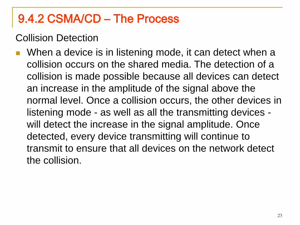
Collision Detection
When a device is in listening mode, it can detect when a
collision occurs on the shared media. The detection of a
collision is made possible because all devices can detect
an increase in the amplitude of the signal above the
normal level. Once a collision occurs, the other devices in
listening mode - as well as all the transmitting devices -
will detect the increase in the signal amplitude. Once
detected, every device transmitting will continue to
transmit to ensure that all devices on the network detect
the collision.

24
9.4.2 CSMA/CD – The Process
Jam Signal and Random Backoff
Once the collision is detected by the transmitting devices,
they send out a jamming signal. This jamming signal is used
to notify the other devices of a collision, so that they will
invoke a backoff algorithm. This backoff algorithm causes all
devices to stop transmitting for a random amount of time,
which allows the collision signals to subside.
After the delay has expired on a device, the device goes back
into the "listening before transmit" mode. A random backoff
period ensures that the devices that were involved in the
collision do not try to send their traffic again at the same time,
which would cause the whole process to repeat. But, this also
means that a third device may transmit before either of the
two involved in the original collision have a chance to re-
transmit.
25
9.4.2 CSMA/CD – The Process
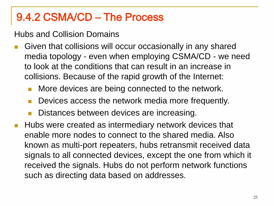
Hubs and Collision Domains
Given that collisions will occur occasionally in any shared
media topology - even when employing CSMA/CD - we need
to look at the conditions that can result in an increase in
collisions. Because of the rapid growth of the Internet:
More devices are being connected to the network.
Devices access the network media more frequently.
Distances between devices are increasing.
Hubs were created as intermediary network devices that
enable more nodes to connect to the shared media. Also
known as multi-port repeaters, hubs retransmit received data
signals to all connected devices, except the one from which it
received the signals. Hubs do not perform network functions
such as directing data based on addresses.

26
9.4.2 CSMA/CD – The Process
Hubs and repeaters are intermediary devices that extend
the distance that Ethernet cables can reach. Because
hubs operate at the Physical layer, dealing only with the
signals on the media, collisions can occur between the
devices they connect and within the hubs themselves.
Further, using hubs to provide network access to more
users reduces the performance for each user because
the fixed capacity of the media has to be shared
between more and more devices.
The connected devices that access a common media via
a hub or series of directly connected hubs make up what
is known as a collision domain. A collision domain is also
referred to as a network segment. Hubs and repeaters
therefore have the effect of increasing the size of the
collision domain.

27
9.4.2 CSMA/CD – The Process
The interconnection of hubs form a physical topology
called an extended star. The extended star can create a
greatly expanded collision domain.
An increased number of collisions reduces the network's
efficiency and effectiveness.
Although CSMA/CD is a frame collision management
system, it was designed to manage collisions for only
limited numbers of devices and on networks with light
network usage. Therefore, other mechanisms are
required when large numbers of users require access
and when more active network access is needed.
Using switches in place of hubs can begin to alleviate
this problem.

28
9.4.3 Ethernet Timings
Latency - The electrical signal that is transmitted takes a certain amount
of time (latency) to propagate (travel) down the cable. Each hub or
repeater in the signal's path adds latency as it forwards the bits from
one port to the next.
Bit Time - For each different media speed, a period of time is required
for a bit to be placed and sensed on the media. This period of time is
referred to as the bit time.
Slot Time - In half-duplex Ethernet, where data can only travel in one
direction at once, slot time becomes an important parameter in
determining how many devices can share a network. For all speeds of
Ethernet transmission at or below 1000 Mbps, the standard describes
how an individual transmission may be no smaller than the slot time.
Interframe Spacing - The Ethernet standards require a minimum
spacing between two non-colliding frames. This gives the media time to
stabilize after the transmission of the previous frame and time for the
devices to process the frame. Referred to as the interframe spacing,
this time is measured from the last bit of the FCS field of one frame to
the first bit of the Preamble of the next frame.

29
9.5 Ethernet Physical Layer
9.5.1 Overview of Ethernet Physical Layer

30
9.5.1 Overview of Ethernet Physical Layer
The differences between standard Ethernet, Fast Ethernet,
Gigabit Ethernet, and 10 Gigabit Ethernet occur at the
Physical layer, often referred to as the Ethernet PHY.
Ethernet is covered by the IEEE 802.3 standards. Four
data rates are currently defined for operation over optical
fiber and twisted-pair cables:
10 Mbps - 10Base-T Ethernet
100 Mbps - Fast Ethernet
1000 Mbps - Gigabit Ethernet
10 Gbps - 10 Gigabit Ethernet
There are many different implementations of Ethernet at
these various data rates, only the more common ones will
be presented.

31
9.5.2 10 and 100 Mbps Ethernet

32
9.5.2 10 and 100 Mbps Ethernet
10 Mbps Ethernet - 10BASE-T
10BASE-T uses Manchester-encoding over two unshielded twisted-
pair cables. The early implementations of 10BASE-T used Cat3
cabling. However, Cat5 or later cabling is typically used today.
10 Mbps Ethernet is considered to be classic Ethernet and uses a
physical star topology. Ethernet 10BASE-T links could be up to 100
meters in length before requiring a hub or repeater.
10BASE-T uses two pairs of a four-pair cable and is terminated at each
end with an 8-pin RJ-45 connector. The pair connected to pins 1 and 2
are used for transmitting and the pair connected to pins 3 and 6 are
used for receiving.
10BASE-T is generally not chosen for new LAN installations. However,
there are still many 10BASE-T Ethernet networks in existence today.
The replacement of hubs with switches in 10BASE-T networks has
greatly increased the throughput available to these networks and has
given Legacy Ethernet greater longevity. The 10BASE-T links
connected to a switch can support either half-duplex or full-duplex
operation.

33
9.5.2 10 and 100 Mbps Ethernet
100 Mbps - Fast Ethernet
In the mid to late 1990s, several new 802.3 standards were
established to describe methods for transmitting data over
Ethernet media at 100 Mbps. These standards used different
encoding requirements for achieving these higher data rates.
100 Mbps Ethernet, also known as Fast Ethernet, can be
implemented using twisted-pair copper wire or fiber media. The
most popular implementations of 100 Mbps Ethernet are:
100BASE-TX using Cat5 or later UTP
100BASE-FX using fiber-optic cable
Because the higher frequency signals used in Fast Ethernet are
more susceptible to noise, two separate encoding steps are
used by 100-Mbps Ethernet to enhance signal integrity.

34
9.5.3 1000 Mbps Ethernet
9.5.4 Ethernet – Future Options: Future Ethernet Speeds
Although 1-Gigabit Ethernet is now widely available and 10-Gigabit
products are becoming more available, the IEEE and the 10-Gigabit
Ethernet Alliance are working on 40-, 100-, or even 160-Gbps
standards. The technologies that are adopted will depend on a number
of factors, including the rate of maturation of the technologies and
standards, the rate of adoption in the market, and the cost of emerging
products
35
9.6.1 Legacy Ethernet – Using Hubs
Classic Ethernet uses shared media and contention-based
media access control. Classic Ethernet uses hubs to
interconnect nodes on the LAN segment. Hubs do not perform
any type of traffic filtering. Instead, the hub forwards all the
bits to every device connected to the hub. This forces all the
devices in the LAN to share the bandwidth of the media.
Additionally, this classic Ethernet implementation often results
in high levels of collisions on the LAN. Because of these
performance issues, this type of Ethernet LAN has limited use
in today's networks. Ethernet implementations using hubs are
now typically used only in small LANs or in LANs with low
bandwidth requirements.
Sharing media among devices creates significant issues as
the network grows.

36
9.6.1 Legacy Ethernet – Using Hubs
Scalability
In a hub network, there is a limit to the amount of bandwidth that
devices can share. With each device added to the shared media, the
average bandwidth available to each device decreases. With each
increase in the number of devices on the media, performance is
degraded.
Latency
Network latency is the amount of time it takes a signal to reach all
destinations on the media. Each node in a hub-based network has to
wait for an opportunity to transmit in order to avoid collisions. Latency
can increase significantly as the distance between nodes is extended.
Latency is also affected by a delay of the signal across the media as
well as the delay added by the processing of the signals through hubs
and repeaters. Increasing the length of media or the number of hubs
and repeaters connected to a segment results in increased latency.
With greater latency, it is more likely that nodes will not receive initial
signals, thereby increasing the collisions present in the network.

37
9.6.1 Legacy Ethernet – Using Hubs
Network Failure
Because classic Ethernet shares the media, any device in the network
could potentially cause problems for other devices. If any device
connected to the hub generates detrimental traffic, the communication
for all devices on the media could be impeded. This harmful traffic could
be due to incorrect speed or full-duplex settings on a NIC.
Collisions
According to CSMA/CD, a node should not send a packet unless the
network is clear of traffic. If two nodes send packets at the same time, a
collision occurs and the packets are lost. Then both nodes send a jam
signal, wait for a random amount of time, and retransmit their packets.
Any part of the network where packets from two or more nodes can
interfere with each other is considered a collision domain. A network
with a larger number of nodes on the same segment has a larger
collision domain and typically has more traffic. As the amount of traffic
in the network increases, the likelihood of collisions increases.
Switches provide an alternative to the contention-based environment of
classic Ethernet.

38
9.6.2 Ethernet – Using Switches

39
9.6.2 Ethernet – Using Switches
Nodes are Connected Directly
In a LAN where all nodes are connected directly to the
switch, the throughput of the network increases
dramatically. The three primary reasons for this increase
are:
Dedicated bandwidth to each port
Collision-free environment
Full-duplex operation
These physical star topologies are essentially point to
point links.

40
9.6.2 Ethernet – Using SwitchesUsing Switches Instead of Hubs
Most modern Ethernet use switches to the end devices and operate
full duplex. Switches provide so much greater throughput than hubs
and increase performance so dramatically. However, there are three
reasons why hubs are still being used.
Availability - LAN switches were not developed until the early
1990s and were not readily available until the mid 1990s. Early
Ethernet networks used UTP hubs and many of them remain in
operation to this day.
Economics - Initially, switches were rather expensive. As the
price of switches has dropped, the use of hubs has decreased
and cost is becoming less of a factor in deployment decisions.
Requirements - The early LAN networks were simple networks
designed to exchange files and share printers. For many
locations, the early networks have evolved into the converged
networks of today, resulting in a substantial need for increased
bandwidth available to individual users. In some circumstances,
however, a shared media hub will still suffice and these
products remain on the market.

41
9.6.3 Switches – Selective Forwarding

42
9.6.3 Switches – Selective Forwarding
Ethernet switches selectively forward individual frames from a
receiving port to the port where the destination node is
connected. This selective forwarding process can be thought of
as establishing a momentary point-to-point connection between
the transmitting and receiving nodes. The connection is made
only long enough to forward a single frame. During this instant,
the two nodes have a full bandwidth connection between them
and represent a logical point-to-point connection.
To be technically accurate, this temporary connection is not
made between the two nodes simultaneously. In essence, this
makes the connection between hosts a point-to-point
connection. In fact, any node operating in full-duplex mode can
transmit anytime it has a frame, without regard to the availability
of the receiving node. This is because a LAN switch will buffer
an incoming frame and then forward it to the proper port when
that port is idle. This process is referred to as store and forward.

43
9.6.3 Switches – Selective Forwarding
With store and forward switching, the switch receives the entire
frame, checks the FCS for errors, and forwards the frame to the
appropriate port for the destination node. Because the nodes do
not have to wait for the media to be idle, the nodes can send
and receive at full media speed without losses due to collisions
or the overhead associated with managing collisions.
Forwarding is Based on the Destination MAC
The switch maintains a table, called a MAC table. that matches
a destination MAC address with the port used to connect to a
node. For each incoming frame, the destination MAC address in
the frame header is compared to the list of addresses in the
MAC table. If a match is found, the port number in the table that
is paired with the MAC address is used as the exit port for the
frame.

44
9.6.3 Switches – Selective Forwarding
The MAC table can be referred to by many different names. It is
often called the switch table. Because switching was derived
from an older technology called transparent bridging, the table
is sometimes called the bridge table. For this reason, many
processes performed by LAN switches can contain bridge or
bridging in their names.
A bridge is a device used more commonly in the early days of
LAN to connect - or bridge - two physical network segments.
Switches can be used to perform this operation as well as
allowing end device connectivity to the LAN. Many other
technologies have been developed around LAN switching. One
place where bridges are prevalent is in Wireless networks.
Wireless Bridges are used to interconnect two wireless network
segments. Both terms - switching and bridging – are in use by
the networking industry.
45
9.6.3 Switches – Selective Forwarding
Switch Operation
To accomplish their purpose, Ethernet LAN switches use five
basic operations: Learning, Aging. Flooding, Selective
Forwarding, Filtering,
Learning
The MAC table must be populated with MAC addresses and
their corresponding ports. The Learning process allows these
mappings to be dynamically acquired during normal operation.
As each frame enters the switch, the switch examines the
source MAC address. Using a lookup procedure, the switch
determines if the table already contains an entry for that MAC
address. If no entry exists, the switch creates a new entry in the
MAC table using the source MAC address and pairs the address
with the port on which the entry arrived. The switch now can use
this mapping to forward frames to this node.

46
9.6.3 Switches – Selective Forwarding
Aging
The entries in the MAC table acquired by the Learning process
are time stamped. This timestamp is used as a means for
removing old entries in the MAC table. After an entry in the MAC
table is made, a procedure begins a countdown, using the
timestamp as the beginning value. After the value reaches 0, the
entry in the table will be refreshed when the switch next receives a
frame from that node on the same port.
Flooding
If the switch does not know to which port to send a frame because
the destination MAC address is not in the MAC table, the switch
sends the frame to all ports except the port on which the frame
arrived. The process of sending a frame to all segments is known
as flooding. The switch does not forward the frame to the port on
which it arrived because any destination on that segment will have
already received the frame. Flooding is also used for frames sent
to the broadcast MAC address.

47
9.6.3 Switches – Selective Forwarding
Selective Forwarding
Selective forwarding is the process of examining a frame's destination
MAC address and forwarding it out the appropriate port. This is the
central function of the switch. When a frame from a node arrives at
the switch for which the switch has already learned the MAC address,
this address is matched to an entry in the MAC table and the frame is
forwarded to the corresponding port. Instead of flooding the frame to
all ports, the switch sends the frame to the destination node via its
nominated port. This action is called forwarding.
Filtering
In some cases, a frame is not forwarded. This process is called frame
filtering. One use of filtering has already been described: a switch
does not forward a frame to the same port on which it arrived. A
switch will also drop a corrupt frame. If a frame fails a CRC check, the
frame is dropped. An additional reason for filtering a frame is security.
A switch has security settings for blocking frames to and/or from
selective MAC addresses or specific ports.

48
9.6.4 Ethernet – Comparing Hubs and Switches

49
9.7.1 ARP Process – Mapping IP to MAC Addresses
The ARP protocol provides two basic functions:
Resolving IPv4 addresses to MAC addresses
Maintaining a cache of mappings
In the event that the gateway entry is not in the table, the normal ARP
process will send an ARP request to retrieve the MAC address
associated with the IP address of the router interface.
Proxy ARP
Using proxy ARP, a router interface acts as if it is the host with the
IPv4 address requested by the ARP request. By "faking" its identity,
the router accepts responsibility for routing packets to the "real"
destination.
Another case where a proxy ARP is used is when a host believes that
it is directly connected to the same logical network as the destination
host. This generally occurs when a host is configured with an
improper mask.
Yet another use for a proxy ARP is when a host is not configured with
a default gateway. By default, Cisco routers have proxy ARP enabled
on LAN interfaces.

50
9.7.3 The ARP Process – Removing Address
Mappings For each device, an ARP cache timer removes ARP entries that have
not been used for a specified period of time. The times differ depending
on the device and its operating system. For example, some Windows
operating systems store ARP cache entries for 2 minutes. If the entry is
used again during that time, the ARP timer for that entry is extended to
10 minutes.
Commands may also be used to manually remove all or some of the
entries in the ARP table. After an entry has been removed, the process
for sending an ARP request and receiving an ARP reply must occur
again to enter the map in the ARP table.
The arp command is used to view and to clear the contents of a
computer's ARP cache. Note that this command, despite its name,
does not invoke the execution of the Address Resolution Protocol in
any way. It is merely used to display, add, or remove the entries of the
ARP table. ARP service is integrated within the IPv4 protocol and
implemented by the device. Its operation is transparent to both upper
layer applications and users.

51
9.7.4 ARP Broadcasts - Issues