The CCM. Overview GF Basics CCM Basics Useful Tools for the CCM –CCM Funding –CCM Oversight tool.
DISTRIBUTION STATEMENT A: DISTRIBUTION UNLIMITED S0570-AC-
CCM-010/8010
DISTRIBUTION STATEMENT A: DISTRIBUTION UNLIMITED
S0570-AC-CCM-010/8010
NAVSEA TECHNICAL PUBLICATION
INDUSTRIAL SHIP SAFETY MANUAL FOR FIRE PREVENTION AND RESPONSE
DISTRIBUTION STATEMENT A: APPROVED FOR PUBLIC RELEASE; DISTRIBUTION IS UNLIMITED.
DESTRUCTION NOTICE: DESTROY BY ANY METHOD THAT WILL PREVENT DISCLOSURE OF CONTENTS OR RECONSTRUCTION OF THE DOCUMENT
PUBLISHED BY DIRECTION OF COMMANDER, NAVAL SEA SYSTEMS COMMAND
06 February 2014
DISTRIBUTION STATEMENT A: DISTRIBUTION UNLIMITED S0570-AC-
CCM-010/8010
DISTRIBUTION STATEMENT A: DISTRIBUTION UNLIMITED
LIST OF EFFECTIVE PAGES
Dispose of superseded pages in accordance with applicable regulations.
Dates of issue for original and subsequent revisions:
Original .......................... 06 February 2014
TOTAL NUMBER OF PAGES IN THIS TECHNICAL MANUAL IS 129, CONSISTING OF THE FOLLOWING:
Page No. Page No.
Title 14-1 through 14-4
i through xiv A-1 through A-4
1-1 through 1-4 B-1 through B-4
2-1 through 2-4 C-1 through C-4
3-1 through 3-14 D-1 through D-4
4-1 through 4-4 E-1 through E-2
5-1 through 5-8 F-1 through F-2
6-1 through 6-6 G-1 through G-6
7-1 through 7-14 H-1 through H-4
8-1 through 8-4
9-1 through 9-2
10-1 through 10-4
11-1 through 11-2
12-1 through 12-6
13-1 through 13-6
DISTRIBUTION STATEMENT A: DISTRIBUTION UNLIMITED S0570-AC-
CCM-010/8010
DISTRIBUTION STATEMENT A: DISTRIBUTION UNLIMITED i
TABLE OF CONTENTS
Chapter/Paragraph Title Page
LIST OF ILLUSTRATIONS ...................................................................................................................................................... ix
LIST OF TABLES...................................................................................................................................................................... ix
COMMANDER’S GUIDANCE ................................................................................................................................................ xi
FOREWORD ............................................................................................................................................................................ xiii
Chapter 1 INTRODUCTION ................................................................................................................................................... 1-1
1.1 PURPOSE. .................................................................................................................................................................... 1-1
1.2 SCOPE. ......................................................................................................................................................................... 1-1
1.2.1 CNO Scheduled Availabilities. ............................................................................................................................. 1-1
1.2.2 Non-CNO Availabilities. ....................................................................................................................................... 1-1
1.2.3 New Construction and Repair Availabilities in Private Shipyards. ....................................................................... 1-2
1.2.4 Ship’s Force. ......................................................................................................................................................... 1-2
1.3 BACKGROUND. ......................................................................................................................................................... 1-2
1.4 RESPONSIBILITIES. .................................................................................................................................................. 1-2
1.4.1 General Guidance. ................................................................................................................................................. 1-2
1.4.2 NSA Responsibilities. ........................................................................................................................................... 1-2
1.4.3 Director of Nuclear Propulsion Responsibilities. .................................................................................................. 1-2
1.4.4 Director, Strategic Systems Programs Responsibilities. ....................................................................................... 1-2
1.4.5 Executive Agent for Damage Control Responsibilities. ........................................................................................ 1-2
1.5 FIRE SAFETY PLAN. ................................................................................................................................................. 1-3
1.6 GLOSSARY OF TERMS. ............................................................................................................................................ 1-3
Chapter 2 ORGANIZATIONAL REQUIREMENTS .............................................................................................................. 2-1
2.1 FIRE SAFETY ORGANIZATION. ............................................................................................................................. 2-1
2.1.1 Fire Safety Council (FSC). .................................................................................................................................... 2-1
2.1.2 Fire Safety Officer (FSO). ..................................................................................................................................... 2-2
2.1.3 Fire Safety Watch (FSW). ..................................................................................................................................... 2-2
2.2 EMERGENCY MANAGEMENT. ............................................................................................................................... 2-3
2.3 TRAINING AND QUALIFICATION REQUIREMENTS. ......................................................................................... 2-3
2.3.1 General. ................................................................................................................................................................. 2-3
2.3.2 Personnel Qualification. ........................................................................................................................................ 2-3
2.3.3 List of Currently Qualified Personnel. .................................................................................................................. 2-3
2.3.4 Training Requirements. ......................................................................................................................................... 2-3
2.3.5 Additional Training Requirements. ....................................................................................................................... 2-3
2.3.6 Instruction and Examination. ................................................................................................................................ 2-3
2.4 FIRE DATA TRACKING AND ANALYSIS. ............................................................................................................. 2-4
2.4.1 Trend Analysis of Shipboard Fires. ....................................................................................................................... 2-4
2.4.2 Trend Analysis of Fire Related Problems. ............................................................................................................ 2-4
2.4.3 Annual Reports. .................................................................................................................................................... 2-4
DISTRIBUTION STATEMENT A: DISTRIBUTION UNLIMITED S0570-AC-
CCM-010/8010
DISTRIBUTION STATEMENT A: DISTRIBUTION UNLIMITED ii
2.5 TROUBLE REPORTS AND MISHAP REPORTS...................................................................................................... 2-4
2.6 AUDITS. ....................................................................................................................................................................... 2-4
2.6.1 Local Audits. ......................................................................................................................................................... 2-4
2.6.2 NAVSEA and CNIC Audits. ................................................................................................................................. 2-4
Chapter 3 FIRE RESPONSE PLANNING ............................................................................................................................... 3-1
3.1 BACKGROUND. ......................................................................................................................................................... 3-2
3.2 FIRE RESPONSE PLAN. ............................................................................................................................................ 3-2
3.2.1 Fire Fighting Principles. ........................................................................................................................................ 3-2
3.2.2 Command and Control. ......................................................................................................................................... 3-2
3.2.3 Designation of Responsibility and Authority. ....................................................................................................... 3-7
3.2.4 Assignment of Designated Personnel to Specific Positions in the Emergency Response Team (ERT). ............... 3-7
3.2.5 Training and Integration of Fire Fighting Services. .............................................................................................. 3-8
3.2.6 Personnel Accountability. ..................................................................................................................................... 3-8
3.2.7 Response Actions. ................................................................................................................................................. 3-8
3.2.8 Fire Fighting Doctrine. .......................................................................................................................................... 3-9
3.2.9 Logistic and In-Hull Support Requirements.......................................................................................................... 3-9
3.2.10 SCBA Recharge Capability. ................................................................................................................................ 3-9
3.2.11 Medical Triage and Treatment. ........................................................................................................................... 3-9
3.2.12 Management of Fire Fighting Effluents. ............................................................................................................. 3-9
3.2.13 Fire Fighting Equipment. .................................................................................................................................. 3-10
3.2.14 Technical Assistance and Coordination. ........................................................................................................... 3-10
3.2.15 Extended Operations Plan. ................................................................................................................................ 3-10
3.2.16 Ship Conditions. ................................................................................................................................................ 3-10
3.2.17 Reporting Procedures. ....................................................................................................................................... 3-10
3.2.18 Procedures for Liaison with Civil Authorities. .................................................................................................. 3-11
3.2.19 Public Affairs. ................................................................................................................................................... 3-11
3.2.20 Accident Information Collection and Storage. .................................................................................................. 3-11
3.2.21 Roles and Responsibilities of Activities. ........................................................................................................... 3-11
3.3 TRAINING. ................................................................................................................................................................ 3-11
3.3.1 F&ES Training. ................................................................................................................................................... 3-11
3.3.2 Initial ERT Training. ........................................................................................................................................... 3-12
3.3.3 National Incident Management System. ............................................................................................................. 3-12
3.3.4 Knowledge. .............................................................................................................................................................. 3-12
3.3.5 Practical Abilities. ............................................................................................................................................... 3-13
3.3.6 Re-verification. ................................................................................................................................................... 3-13
3.3.7 Mutual Aid Agreements. ..................................................................................................................................... 3-13
3.4 RAPID RESPONSE DAMAGE CONTROL CONEX BOX, SUBMARINES. ......................................................... 3-13
3.4.1 Damage Control (DC) Equipment. ...................................................................................................................... 3-13
3.4.2 Storage of DC Equipment. .................................................................................................................................. 3-13
3.4.3 Custody of DC Equipment. ................................................................................................................................. 3-13
DISTRIBUTION STATEMENT A: DISTRIBUTION UNLIMITED S0570-AC-
CCM-010/8010
DISTRIBUTION STATEMENT A: DISTRIBUTION UNLIMITED iii
3.4.4 Alternate Storage Location. ................................................................................................................................. 3-13
3.4.5 Staging of DC Equipment. .................................................................................................................................. 3-13
3.4.6 Accessibility of DC Equipment. .......................................................................................................................... 3-13
3.4.7 Transition to Habitability. ................................................................................................................................... 3-13
3.5 FIRE LANES. ............................................................................................................................................................. 3-14
3.5.1 Fire Lane Width. ................................................................................................................................................. 3-14
3.5.2 Vertical Clearance. .............................................................................................................................................. 3-14
3.5.3 Angle of Approach/Departure. ............................................................................................................................ 3-14
3.5.4 Wintertime Maintenance. .................................................................................................................................... 3-14
3.5.5 Fire Lane Markings. ............................................................................................................................................ 3-14
3.5.6 Waiver Request. .................................................................................................................................................. 3-14
3.5.7 Approval to Temporarily Block a Fire Lane. ...................................................................................................... 3-14
Chapter 4 HOT WORK AND FIRE WATCH ......................................................................................................................... 4-1
4.1 HOT WORK MEMORANDUM OF AGREEMENT. ................................................................................................. 4-1
4.1.1 Classifications of Hot Work. ................................................................................................................................. 4-1
4.1.2 Hot Work MOA. ................................................................................................................................................... 4-1
4.2 HOT WORK AUTHORIZATION. .............................................................................................................................. 4-2
4.2.1 Written Notice. ...................................................................................................................................................... 4-2
4.2.2 Signing Authority. ................................................................................................................................................. 4-2
4.2.3 Posting of Notice. .................................................................................................................................................. 4-2
4.2.4 Notice to the CO’s Representative. ....................................................................................................................... 4-2
4.3 GAS-FREE PROCEDURES AND SPECIAL HAZARDS. ......................................................................................... 4-2
4.3.1 Governance for Gas Free Procedures. ................................................................................................................... 4-2
4.3.2 Restricted Areas for Hot Work. ............................................................................................................................. 4-2
4.3.3 Coverings. ............................................................................................................................................................. 4-2
4.3.4 Lines/Piping Containing Flammable or Combustible Fluids. ............................................................................... 4-2
4.3.5 Proximity of Flammables and Combustibles. ....................................................................................................... 4-3
4.3.6 Ammunition or Explosives.................................................................................................................................... 4-3
4.3.7 Battery Charging Operations. ................................................................................................................................ 4-3
4.3.8 Additional Precautions. ......................................................................................................................................... 4-3
4.4 FIRE WATCH REQUIREMENTS AND TRAINING. ................................................................................................ 4-3
4.4.1 Fire Watch Policy. ................................................................................................................................................. 4-3
4.4.2 Additional Duties During Hot Work. .................................................................................................................... 4-3
4.4.3 Limitations to Single Fire Watch with Multiple Hot Workers. ............................................................................. 4-3
4.4.4 Hot Work Involving Multiple Levels. ................................................................................................................... 4-3
4.4.5 Bulkhead or Deck Hot Work. ................................................................................................................................ 4-3
4.4.6 Blind Compartment Hot Work. ............................................................................................................................. 4-3
4.4.7 Communication Between Fire Watches. ............................................................................................................... 4-3
4.4.8 Fire Extinguishers. ................................................................................................................................................ 4-4
4.4.9 Fire Watch Training. ............................................................................................................................................. 4-4
DISTRIBUTION STATEMENT A: DISTRIBUTION UNLIMITED S0570-AC-
CCM-010/8010
DISTRIBUTION STATEMENT A: DISTRIBUTION UNLIMITED iv
Chapter 5 INDUSTRIAL MATERIALS USED AND STORED SHIPBOARD ..................................................................... 5-1
5.1 FLAMMABLE AND COMBUSTIBLE MATERIAL. ................................................................................................ 5-2
5.1.1 Materials Used Shipboard By Maintenance Activities. ......................................................................................... 5-2
5.1.2 Consumable Materials. .......................................................................................................................................... 5-2
5.1.3 Fire Resistant Materials. ........................................................................................................................................ 5-3
5.1.4 Plastic Trash Cans. ................................................................................................................................................ 5-3
5.1.5 Plastic Bodied Tools. ............................................................................................................................................ 5-3
5.1.6 Metal Canister Vacuum Cleaners. ......................................................................................................................... 5-3
5.1.7 Smoking Policies. .................................................................................................................................................. 5-3
5.1.8 Flammable Compressed Gas Cylinders. ............................................................................................................... 5-3
5.1.9 Flammable and Combustible Liquid Stowage. ..................................................................................................... 5-3
5.1.10 Combustible Materials and Waste. ...................................................................................................................... 5-4
5.1.11 Large Quantity Drums. ........................................................................................................................................ 5-4
5.1.12 Fueled Equipment-Moving Vehicles. .................................................................................................................. 5-4
5.1.13 Fueling Operations. ............................................................................................................................................. 5-4
5.1.14 Openings Above the Reactor Compartment. ....................................................................................................... 5-4
5.2 STOWAGE OF SHIP’S FLAMMABLE AND COMBUSTIBLE MATERIAL. ......................................................... 5-4
5.2.1 Flammable Gas Stowage. ...................................................................................................................................... 5-4
5.2.2 Flammable Industrial Gas. .................................................................................................................................... 5-5
5.2.3 Oxidizers. .............................................................................................................................................................. 5-5
5.2.4 CO2 Absorption Chemicals. .................................................................................................................................. 5-5
5.2.5 Refrigerant and Air Conditioning Gas Cylinders (R134, R114, R12, etc.). .......................................................... 5-5
5.2.6 Ammunitions and Explosives. ............................................................................................................................... 5-5
5.2.7 Ship’s Hazardous Material Storage Facilities. ...................................................................................................... 5-5
5.3 TEMPORARY STRUCTURES AND LAYDOWN AREAS. ..................................................................................... 5-5
5.3.1 Temporary Structures. ........................................................................................................................................... 5-5
5.3.2 Use of Wood. ........................................................................................................................................................ 5-5
5.3.3 Sizing and Positioning of Structures. .................................................................................................................... 5-6
5.3.4 Storage of Material. ............................................................................................................................................... 5-6
5.4 FIRE SAFETY INSPECTIONS. .................................................................................................................................. 5-7
5.4.1 Fire Prevention and Safety Inspections. ................................................................................................................ 5-7
5.4.2 Minimum Requirements for Inspection. ............................................................................................................... 5-7
Chapter 6 FIRE DETECTION .................................................................................................................................................. 6-1
6.1 TEMPORARY INSTALLATION OF AUTOMATIC FIRE DETECTION SYSTEM ON SUBMARINES. ............. 6-1
6.1.1 Applicability .......................................................................................................................................................... 6-1
6.1.2 Combination Smoke and Heat Detector Hardware Requirements. ....................................................................... 6-2
6.1.3 Alarm Panel Hardware Requirements. .................................................................................................................. 6-2
6.1.4 Automatic Fire Detection System Installation Criteria. ........................................................................................ 6-3
6.1.5 Automatic Fire Detection System Testing. ........................................................................................................... 6-4
6.1.6 Automatic Fire Detection System Protection. ....................................................................................................... 6-4
DISTRIBUTION STATEMENT A: DISTRIBUTION UNLIMITED S0570-AC-
CCM-010/8010
DISTRIBUTION STATEMENT A: DISTRIBUTION UNLIMITED v
6.1.7 Automatic Fire Detection System Installation and Removal. ............................................................................... 6-5
6.2 [RESERVED FOR SURFACE SHIP DETECTION REQUIREMENTS]. .................................................................. 6-5
Chapter 7 FIRE FIGHTING SYSTEMS .................................................................................................................................. 7-1
7.1 FIRE PROTECTION SYSTEMS. ................................................................................................................................ 7-2
7.1.1 Fire Fighting Systems. .......................................................................................................................................... 7-2
7.1.2 Hazards of Fixed Extinguishing Systems. ............................................................................................................. 7-2
7.1.3 Pumping and Dewatering Capability. ................................................................................................................... 7-3
7.1.4 Operation of Major Machinery in Engineering Spaces. ........................................................................................ 7-3
7.1.5 Liquid Fuel Pumping and Transfer. ...................................................................................................................... 7-3
7.1.6 Mechanical Aqueous Film Forming Foam Producing Equipment. ....................................................................... 7-3
7.1.7 Portable Fire Extinguisher Requirements. ............................................................................................................. 7-3
7.1.8 Hose and Hose Reel Protection. ............................................................................................................................ 7-4
7.1.9 Drydock Fire Fighting Requirements. ................................................................................................................... 7-4
7.2 SUBMARINES. ............................................................................................................................................................ 7-5
7.2.1 General. ................................................................................................................................................................. 7-5
7.2.2 Temporary Firemain and Water Supply. ............................................................................................................... 7-5
7.2.3 Temporary Topside Hose Station Manifolds. ....................................................................................................... 7-6
7.2.4 Temporary Internal Hose Reels. ............................................................................................................................ 7-6
7.2.5 Temporary Firemain, Hose Station, and Hose Reel Testing. ................................................................................ 7-7
7.3 SURFACE SHIPS. ........................................................................................................................................................ 7-8
7.3.1 General. ................................................................................................................................................................. 7-8
7.3.2 Water Supply Requirements for Fire Fighting. ..................................................................................................... 7-8
Chapter 8 ALARMS AND COMMUNICATIONS ................................................................................................................. 8-1
8.1 SHIPBOARD FIRE REPORTING SYSTEM. ............................................................................................................. 8-1
8.1.1 Fire Reporting Devices. ........................................................................................................................................ 8-1
8.1.2 Annunciator Panel. ................................................................................................................................................ 8-1
8.1.3 Reporting to Emergency Dispatch Center. ............................................................................................................ 8-2
8.1.4 Defective or Inoperative Alarms. .......................................................................................................................... 8-2
8.1.5 Fire Reporting in DryDock. .................................................................................................................................. 8-2
8.2 CASUALTY GENERAL ANNOUNCING SYSTEM. ................................................................................................ 8-2
8.2.1 Temporary System. ............................................................................................................................................... 8-2
8.2.2 Testing of Systems. ............................................................................................................................................... 8-2
8.2.3 Brief Outages. ....................................................................................................................................................... 8-2
8.2.4 Hot Work............................................................................................................................................................... 8-2
8.3 DAMAGE CONTROL CENTRAL/CASCON STATION, SUBMARINES. .............................................................. 8-2
8.3.1 Location of CASCON Station. .............................................................................................................................. 8-2
8.3.2 Fire Detection System Alarm Panel. ..................................................................................................................... 8-2
8.3.3 Required Items at CASCON Station. .................................................................................................................... 8-2
8.4 DAMAGE CONTROL CENTRAL/QUARTERDECK, SURFACE SHIPS................................................................ 8-3
8.4.1 Damage Control Policies and Procedures. ............................................................................................................ 8-3
DISTRIBUTION STATEMENT A: DISTRIBUTION UNLIMITED S0570-AC-
CCM-010/8010
DISTRIBUTION STATEMENT A: DISTRIBUTION UNLIMITED vi
8.4.2 Alternate DCC. ...................................................................................................................................................... 8-3
8.4.3 DCC Located Off Ship. ......................................................................................................................................... 8-3
8.4.4 Receiving and Escorting F&ES Officers. .............................................................................................................. 8-3
8.4.5 Required Items at DCC/Quarterdeck. ................................................................................................................... 8-3
8.5 STOP HOT WORK ALARM SYSTEM. ..................................................................................................................... 8-4
8.5.1 Requirements. ....................................................................................................................................................... 8-4
8.5.2 Installed Alarm and Announcing System. ............................................................................................................. 8-4
8.6 EVACUATE SHIP ALARM SYSTEM. ...................................................................................................................... 8-4
8.6.1 Requirements. ....................................................................................................................................................... 8-4
8.6.2 Installed Alarm and Announcing System. ............................................................................................................. 8-4
8.7 PORTABLE RADIOS. ................................................................................................................................................. 8-4
Chapter 9 LIGHTING .............................................................................................................................................................. 9-1
9.1 PERMANENT LIGHTING REQUIREMENTS. ......................................................................................................... 9-1
9.2 TEMPORARY LIGHTING REQUIREMENTS. ......................................................................................................... 9-1
9.2.1 Lighting Guards. ................................................................................................................................................... 9-1
9.2.2 Electric Cords. ....................................................................................................................................................... 9-1
9.2.3 Exposed Non-current-carrying Metal Parts. .......................................................................................................... 9-1
9.2.4 Portable Emergency Lighting Equipment. ............................................................................................................ 9-1
9.2.5 Dark Spaces. .......................................................................................................................................................... 9-1
9.2.6 Restricted Usage.................................................................................................................................................... 9-1
Chapter 10 SHIPBOARD ACCESS/EGRESS AND ROUTING OF TEMPORARY SERVICES ................................ 10-1
10.1 SHIPBOARD ACCESS AND EGRESS NUMBER AND LOCATION. ................................................................. 10-1
10.1.1 Egress Requirements (Submarines)................................................................................................................... 10-1
10.1.2 Shipboard Access (Submarines). ....................................................................................................................... 10-1
10.1.3 Access to Machinery Space (Surface Ships). .................................................................................................... 10-2
10.1.4 Shipboard Access (Surface Ships). ................................................................................................................... 10-2
10.1.5 Securing of Brow/Gangway. ............................................................................................................................. 10-2
10.2 MAINTAINING ACCESS AND EGRESS CONDITION. ...................................................................................... 10-2
10.2.1 Brow/Gangway Requirements. ......................................................................................................................... 10-2
10.2.2 Safety Nets. ....................................................................................................................................................... 10-2
10.2.3 Condition of Brow/Gangways. .......................................................................................................................... 10-2
10.2.4 Marking Routes of Escape. ............................................................................................................................... 10-2
10.2.5 Use of Announcing System for Access and Egress Routes. .............................................................................. 10-2
10.3 EMERGENCY AIR BREATHING SYSTEM (SUBMARINES). ........................................................................... 10-2
10.3.1 Required Emergency Air Breathing System. .................................................................................................... 10-2
10.3.2 Service to Maneuvering. ................................................................................................................................... 10-2
10.3.3 Breathing Air Supply for Egress. ...................................................................................................................... 10-3
10.4 ROUTING OF TEMPORARY SERVICES. ............................................................................................................ 10-3
10.4.1 Pre-plan for Temporary Services. ..................................................................................................................... 10-3
10.4.2 Routing of Temporary Services Through Installed Ship Hull Openings........................................................... 10-3
DISTRIBUTION STATEMENT A: DISTRIBUTION UNLIMITED S0570-AC-
CCM-010/8010
DISTRIBUTION STATEMENT A: DISTRIBUTION UNLIMITED vii
10.4.3 Additional Hull Cuts. ........................................................................................................................................ 10-3
10.4.4 Materials used for Suspending Temporary Services. ........................................................................................ 10-3
10.4.5 Drawing of Services Entering the Ship. ............................................................................................................ 10-3
10.4.6 Marking Temporary Services. ........................................................................................................................... 10-4
10.4.7 Quick Disconnect Fittings. ................................................................................................................................ 10-4
10.4.8 Air Flow Control. .............................................................................................................................................. 10-4
10.4.9 Service Lines Crossing Fire Zone Boundaries. ................................................................................................. 10-4
10.4.10 Protection during Installation, Operation and Removal of Temporary Services. ............................................ 10-4
Chapter 11 FIRE AND SMOKE BOUNDARIES .................................................................................................................. 11-1
11.1 FIRE ZONE BOUNDARIES. ................................................................................................................................... 11-1
11.1.1 Requirements for Fire Zone Boundaries. .......................................................................................................... 11-1
11.1.2 Fire Zone Boundaries (Submarines).................................................................................................................. 11-1
11.1.3 Temporary Access Cuts through Fire Zone Boundaries. .................................................................................. 11-1
11.1.4 Disabling/Degrading Fire Zone Boundaries. ..................................................................................................... 11-1
11.1.5 Marking Fire Zone Boundaries. ........................................................................................................................ 11-1
11.1.6 Record of Boundary Openings. ......................................................................................................................... 11-1
11.1.7 Boundaries on Carrier Type Ships. ................................................................................................................... 11-1
11.2 FIRE AND SMOKE BOUNDARIES. ...................................................................................................................... 11-1
11.2.1 Fire Boundaries. ................................................................................................................................................ 11-1
11.2.2 Smoke Boundaries. ........................................................................................................................................... 11-2
11.2.3 Traverse Bulkheads versus Compartments. ...................................................................................................... 11-2
11.2.4 Acceptable Boundaries. ..................................................................................................................................... 11-2
Chapter 12 FIRE DRILL REQUIREMENTS......................................................................................................................... 12-1
12.1 PERIODIC FIRE DRILLS. ...................................................................................................................................... 12-1
12.2 DRILL ATTRIBUTE REQUIREMENTS. ............................................................................................................... 12-1
12.2.1 Attributes for All Fire Drills.............................................................................................................................. 12-1
12.2.2 Selective Attributes for Fire Drills. ................................................................................................................... 12-2
12.3 DRILL EVALUATION. ........................................................................................................................................... 12-3
12.4 DRILL TEAM, GUIDES, AND POST-EVENT EVALUATION. .......................................................................... 12-3
12.4.1 SRCA Drill Team. ............................................................................................................................................. 12-3
12.4.2 Drill Guide. ....................................................................................................................................................... 12-3
12.4.3 Drill Termination. ............................................................................................................................................. 12-3
12.4.4 Response to Actual Casualty. ............................................................................................................................ 12-3
12.4.5 Realistic Fire Scenario. ..................................................................................................................................... 12-3
12.4.6 Minimize Simulations. ...................................................................................................................................... 12-4
12.4.7 SRCA Response. ............................................................................................................................................... 12-4
12.4.8 Drill Hotwash. ................................................................................................................................................... 12-4
12.4.9 Drill Evaluation. ................................................................................................................................................ 12-4
12.4.10 Written Report. ................................................................................................................................................ 12-4
12.4.11 Action for an Unsatisfactory Grade. ................................................................................................................ 12-4
DISTRIBUTION STATEMENT A: DISTRIBUTION UNLIMITED S0570-AC-
CCM-010/8010
DISTRIBUTION STATEMENT A: DISTRIBUTION UNLIMITED viii
12.4.12 Submitting the Report. .................................................................................................................................... 12-5
12.4.13 Fire Response Capabilities during the Drill. ................................................................................................... 12-5
12.4.14 Duration of Drills. ........................................................................................................................................... 12-5
12.5 DRILL FREQUENCY. ............................................................................................................................................. 12-5
12.5.1 Burden of Requirements.................................................................................................................................... 12-5
12.5.2 Back-shift Drill.................................................................................................................................................. 12-5
Chapter 13 MAJOR FIRE DRILL REQUIREMENTS .......................................................................................................... 13-1
13.1 DRILL ATTRIBUTE REQUIREMENTS. ............................................................................................................... 13-1
13.2 DRILL EVALUATION. ........................................................................................................................................... 13-3
13.3 DRILL TEAM, GUIDES, AND POST-EVENT EVALUATION. .......................................................................... 13-4
13.3.1 Major Fire Drill Team. ...................................................................................................................................... 13-4
13.3.2 Drill Evaluators. ................................................................................................................................................ 13-4
13.3.3 Drill Guide. ....................................................................................................................................................... 13-4
13.3.4 Drill Hotwash. ................................................................................................................................................... 13-5
13.3.5 Drill Evaluation Team. ...................................................................................................................................... 13-5
13.3.6 Evaluation of Simulated Press Conference/Availability. .................................................................................. 13-5
13.3.7 NAVSEA and CNIC Review. ........................................................................................................................... 13-5
13.3.8 Drill Brief, Execution, and Debrief Schedule. .................................................................................................. 13-5
13.3.9 Written Evaluations/Reports. ............................................................................................................................ 13-5
13.3.10 Nuclear Powered Warships. ............................................................................................................................ 13-5
13.3.11 Non-Nuclear Powered Warships At Private Repair SRCAs. .......................................................................... 13-5
Chapter 14 SPECIAL SUBMARINE SHIPBOARD FIRE HAZARDS ................................................................................ 14-1
14.1 GENERAL. ............................................................................................................................................................... 14-1
14.2 BATTERY COMPARTMENT CASUALTIES. ...................................................................................................... 14-1
14.2.1 General. ............................................................................................................................................................. 14-1
14.2.2 Hydrogen Explosion. ......................................................................................................................................... 14-1
14.3 SPECIAL HULL TREATMENT (SHT) FIRES IN DRYDOCK. ............................................................................ 14-2
14.3.1 General. ............................................................................................................................................................. 14-2
14.3.2 SHT Materials. .................................................................................................................................................. 14-2
14.3.3 Flammability and Fire Spread. .......................................................................................................................... 14-2
14.3.4 SHT Flammability. ............................................................................................................................................ 14-2
14.3.5 Fire Spread. ....................................................................................................................................................... 14-2
14.3.6 Extinguishing Methods. .................................................................................................................................... 14-2
14.3.7 Fire Attack. ........................................................................................................................................................ 14-2
Appendix A Principles of Emergency Response for a Shipboard Fire .................................................................................... A-1
Appendix B Fully Developed Incident Management Structure for Shipboard Fire Emergency ............................................. B-1
Appendix C Engineered Fire Response Strategy ..................................................................................................................... C-1
Appendix D Rapid Response Damage Control CONEX Box, Submarines ............................................................................ D-1
Appendix E Combination Smoke and Heat Detector Spacing................................................................................................. E-1
Appendix F Drill Guide and Authorization Forms .................................................................................................................. F-1
DISTRIBUTION STATEMENT A: DISTRIBUTION UNLIMITED S0570-AC-
CCM-010/8010
DISTRIBUTION STATEMENT A: DISTRIBUTION UNLIMITED ix
Appendix G Glossary .............................................................................................................................................................. G-1
Appendix H List of Acronyms ................................................................................................................................................ H-1
LIST OF ILLUSTRATIONS
Figure Title Page
Figure 3-1. Incident Management Structure for Shipboard Fire Emergency (Stage 1). .......................................................... 3-4 Figure 3-2. Incident Management Structure for Shipboard Fire Emergency (Stage 2). .......................................................... 3-5 Figure 3-3. Incident Management Structure for Shipboard Fire Emergency (Stage 3). .......................................................... 3-5 Figure 3-4a. Incident Management Structure for Shipboard Fire Emergency (Stage 4). ......................................................... 3-6 Figure 3-4b. Integrated In-Hull Operations Section. ............................................................................................................... 3-6 Figure 7-1. Shipyard/F&ES Water Supply System Diagram................................................................................................. 7-13 Figure B-1. Incident Management Structure for Shipboard Fire Emergency (Fully Developed). .......................................... B-1 Figure B-2. Integrated In-Hull Operations Section (Fully Developed). ................................................................................. B-3 Figure D-1. Damage Control CONEX Box (Top View). ....................................................................................................... D-3 Figure D-2. Damage Control CONEX Box (Cutaway Inboard Profile, Left). ....................................................................... D-3 Figure D-3. Damage Control CONEX Box (Cutaway Inboard Profile, Right). ..................................................................... D-4 Figure D-4. Damage Control CONEX Box (Interior View). .................................................................................................. D-4 Figure E-1. Combination Smoke and Heat Detector Spacing, Smooth Overheads. ............................................................... E-1 Figure E-2. Combination Smoke and Heat Detector Spacing [30 ft Listed Spacing], Rectangular Area. .............................. E-2
LIST OF TABLES
Table Title Page
Table 3-1. NIMS and NRF Training Requirements for Designated Personnel...................................................................... 3-12 Table 3-2. FEMA On-line Training Courses. ........................................................................................................................ 3-12 Table 7-1. Temporary Hose Reel Connections for SSN-688 LOS ANGELES Class. ............................................................ 7-6 Table 7-2. Temporary Hose Reel Connections for SSBN/SSGN-726 OHIO Class. ............................................................... 7-7 Table 7-3. Fire Protection Water Supply Requirements. ......................................................................................................... 7-9 Table 7-4. Hose Capacity (gpm)
1/. ........................................................................................................................................ 7-11
Table C-1. Engineered Fire Response Strategy Attributes. .................................................................................................... C-2 Table D-1. Damage Control Equipment Inventory. ................................................................................................................ D-1
DISTRIBUTION STATEMENT A: DISTRIBUTION UNLIMITED S0570-AC-
CCM-010/8010
DISTRIBUTION STATEMENT A: DISTRIBUTION UNLIMITED x
THIS PAGE INTENTIONALLY LEFT BLANK.
DISTRIBUTION STATEMENT A: DISTRIBUTION UNLIMITED S0570-AC-
CCM-010/8010
DISTRIBUTION STATEMENT A: DISTRIBUTION UNLIMITED xi
COMMANDER’S GUIDANCE
On 23 May 2012, a major fire occurred on board USS MIAMI (SSN 755) during her overhaul at Portsmouth Naval
Shipyard, which caused major damage to the forward compartment of the submarine and resulted in her inactivation
from the Fleet ten years before scheduled. While the cause of the fire was arson, there were many lessons learned
from combating this casualty, and Navy leadership recognized a clear need to raise our standards and capabilities,
and develop cost effective solutions to improve fire prevention, detection, immediate response, and extended
response for ships undergoing industrial maintenance.
Developed and reviewed by industrial and fire safety experts across the Navy, including NAVSEA, CNIC, SSP,
Naval Reactors, both Fleets, and all TYCOMs, the manual represents a major accomplishment toward improving
shipboard fire safety during industrial work. It applies to all Ship Repair and/or Construction Activities (SRCAs),
both public and private, and to all ship availabilities. It is the right long-term response to the watershed event the
MIAMI fire represents. It is imperative that all organizations implement the applicable requirements of this manual
and ensure their fire safety and response procedures and capabilities are solid. The Navy cannot afford another
setback, such as loss of MIAMI, due to a major casualty or fire.
With the current and projected challenging fiscal environment, the Navy cannot afford blind compliance, and this
manual will present a unique challenge in implementation because it covers all ships and all availabilities. There are
tiered risk mitigations based on the amount and complexity of the work performed (e.g., operational condition of
ship’s fire fighting systems, communication and alarm systems, ship’s force habitability, etc.). I expect thoughtful
consideration by the Naval Shipyards (NSYs), Regional Maintenance Centers (RMCs), Trident Refit Facilities
(TRFs), Fleet Maintenance Activities (FMAs), private repair shipyards, new construction shipyards, and ships in
determining how to apply the requirements for each availability. Local engineering organizations and Fire Safety
Councils (FSCs) are empowered to address unique situations. These groups and their parent organizations are
expected to be judicious and make smart decisions to achieve an optimum balance of all the risks – fire safety as
well as cost and schedule.
The manual requires the SRCA to document how requirements will be implemented on each availability in a formal
Memorandum of Agreement (MOA) with the ship. The MOAs provide formality to the process and ensure that all
organizations understand their roles and responsibilities. The MOAs will also be reviewed for lessons learned, and
provide a vehicle for NAVSEA and the TYCOMs to evaluate how well the SRCAs and the ships are balancing the
risks.
As we move forward with the implementation of this new manual, all organizations should provide feedback and
improvement recommendations. The intent of this manual is to provide the most cost effective practices that
minimize the likelihood of another substantial shipboard fire but ensure we have the capability to deal with it should
one occur. I am counting on all of you to be safe, smart, and effective. Remember, it’s all about the ships.
W.H. Hilarides
Vice Admiral
Commander, Naval Sea Systems Command
DISTRIBUTION STATEMENT A: DISTRIBUTION UNLIMITED S0570-AC-
CCM-010/8010
DISTRIBUTION STATEMENT A: DISTRIBUTION UNLIMITED xii
THIS PAGE INTENTIONALLY LEFT BLANK.
DISTRIBUTION STATEMENT A: DISTRIBUTION UNLIMITED S0570-AC-
CCM-010/8010
DISTRIBUTION STATEMENT A: DISTRIBUTION UNLIMITED xiii
FOREWORD
This specification covers the requirements for the prevention of, detection of, immediate response, and extended
response to fires onboard Navy vessels during industrial work to ensure safety of equipment and personnel.
TMDER INSTRUCTIONS
Ships, training activities, supply points, depots, Naval Shipyards and Supervisors of Shipbuilding are requested to
arrange for the maximum practical use and evaluation of NAVSEA and SPAWAR technical manuals (TMs). All
errors, omissions, discrepancies, and suggestions for improvement to NAVSEA and SPAWAR TMs shall be
submitted as a Technical Manual Deficiency/Evaluation Report (TMDER). All feedback comments shall be
thoroughly investigated and originators will be advised of action resulting there from.
The NAVSEA/SPAWAR Technical Manual Deficiency/Evaluation Report form, NAVSEA 4160/1 is included at
the back of the TM.
Copies of form NAVSEA 4160/1 may also be downloaded from:
https://nsdsa.nmci.navy.mil/nsdsarepository/TMDER_BLANK_REV_9-2010-1.pdf
The following methods are available for generation and submission of TMDERs against unclassified TMs:
For those with a Technical Data Management Information System (TDMIS) account, the most expedient
and preferred method of TMDER generation and submission is via the TDMIS website at:
https://mercury.tdmis.navy.mil.
For those without a TDMIS account, generate and submit TMDER via the Naval Systems Data Support
Activity (NSDSA) website at: https://mercury.tdmis.navy.mil/def_external/pubsearch.cfm. (TDMIS
accounts may be requested at https://nsdsa.nmci.navy.mil.)
When internet access is not available, submit TMDER via hardcopy to:
COMMANDER
CODE 310 TMDERs
NAVSURFWARCENDIV NSDSA
4363 MISSILE WAY, BLDG 1389
PORT HUENEME, CA 93043-4307
TMDERs against classified/restricted (includes all NOFORN) TMs must be submitted using the hardcopy
method cited above.
Urgent priority TM deficiencies shall be reported by Naval message with transmission to Port Hueneme
Division, Naval Surface Warfare Center (Code 310), Port Hueneme, CA. Local message handling
procedures shall be used. The message shall identify each TM deficiency by TM identification number and
title. This method shall be used in those instances where a TM deficiency constitutes an urgent problem,
(i.e., involves a condition, which if not corrected, could result in injury to personnel, damage to the
equipment, or jeopardy to the safety or success of the mission).
Complete instructions for TMDER generation and submission are detailed on the NSDSA website at:
https://nsdsa.nmci.navy.mil/tmder/tmder.asp?lvl=1.

DISTRIBUTION STATEMENT A: DISTRIBUTION UNLIMITED S0570-AC-
CCM-010/8010
DISTRIBUTION STATEMENT A: DISTRIBUTION UNLIMITED xiv
THIS PAGE INTENTIONALLY LEFT BLANK.
DISTRIBUTION STATEMENT A: DISTRIBUTION UNLIMITED S0570-AC-
CCM-010/8010
DISTRIBUTION STATEMENT A: DISTRIBUTION UNLIMITED 1-1
Chapter 1 INTRODUCTION
References
(a) S9AA0-AB-GOS-010, General Overhaul Specifications For Overhaul of Surface Ships (GSO)
(b) S0902-018-2010, General Overhaul Specifications For Deep Diving SSBN/SSN Submarines (DDGOS)
(c) S9002-AK-CCM-010/6010, Industrial Ship Safety Manual For Submarines
(d) COMUSFLTFORCOMINST 4790.3, Joint Fleet Maintenance Manual
(e) COMNAVSEA ltr 11320 Ser 04X/370 of 21 Nov 12; Subj: Emergency Fire Response Planning and Execution of Major
Fire Drills at Naval Shipyards; Updated Guidance and Request for Action
(f) United States Navy Regulations
(g) OPNAVINST 11320.23, Navy Fire and Emergency Services Program
(h) Occupational Safety and Health Standards for Shipyard Employment, 29 CFR Part 1915 Subpart P, Fire Protection in
Shipyard Employment
(i) CNO ltr 3541 Ser N00/100080 of 5 Dec 12; Subj: Damage Control Modernization and Improvement
(j) COMUSFLTFORCOM Norfolk VA Msg DTG 241251Z APR 13; Subj: Designation as Executive Agent for Damage
Control
1.1 PURPOSE. The purpose of this manual is to provide a single source document of requirements for the prevention of,
detection of, and response to fires onboard Navy vessels during industrial work to ensure safety of equipment and personnel.
1.2 SCOPE. The requirements of this manual are applicable to all Ship Repair and/or Construction Activities (SRCAs) that
perform industrial work (maintenance, repair, modernization, inactivation, and/or construction) on Navy vessels and are
implemented in ship availabilities and construction projects as specified below. This includes Naval Shipyards (NSYs),
Regional Maintenance Centers (RMCs), Trident Refit Facilities (TRFs), Fleet Maintenance Activities (FMAs), private repair
shipyards, and new construction shipyards. The requirements provide tiered risk mitigations based on the amount and
complexity of the work performed (e.g., operational condition of ship’s fire fighting systems, communication and alarm
systems, Ship’s Force (SF) habitability, etc.).
1.2.1 CNO Scheduled Availabilities. The requirements apply to all Chief of Naval Operations (CNO) scheduled
availabilities of commissioned ships. However, the details of implementation will vary depending on the platform, type of
availability, condition of the ship, and work planned. Naval Supervising Authorities (NSAs) shall ensure that the SRCA
executing the CNO Availability develops a Memorandum of Agreement (MOA) with the ship to ensure each organization
agrees with and understands how the requirements will be implemented, and is aware of and acknowledges their assigned
roles and responsibilities. Where MOAs have been instituted by an established process (e.g., TYCOM Instruction for CVN
Planned Incremental Availabilities (PIA) and Docking Planned Incremental Availabilities (DPIA), project execution
strategies, or SRCA standard operating procedures), this agreement should be incorporated into the existing process. These
MOAs shall be reviewed in post availability hot washes to identify lessons learned and make any needed improvements.
1.2.2 Non-CNO Availabilities. For non-CNO scheduled availabilities, the requirements shall be implemented in whole or in
part whenever the Ship’s Commanding Officer (CO), Immediate Superior in Command (ISIC)/ Type Commander (TYCOM)
(as determined by the TYCOM), Naval Supervising Authority (NSA)/Lead Maintenance Activity (LMA) and SRCA assess
the risks and agree that the scope of work and condition of organic fire fighting capabilities warrant implementation.
Agreements reached should be documented via a MOA before the start of each availability, and any disagreements should be
raised to the TYCOM, Naval Sea Systems Command (NAVSEA), and/or Fleet as applicable for resolution. The MOA shall
also include how the requirements will be implemented and assigned roles and responsibilities as discussed in 1.2.1 above.
DISTRIBUTION STATEMENT A: DISTRIBUTION UNLIMITED S0570-AC-
CCM-010/8010
DISTRIBUTION STATEMENT A: DISTRIBUTION UNLIMITED 1-2
1.2.3 New Construction and Repair Availabilities in Private Shipyards. For new construction ships and repair availabilities
in private shipyards, the requirements apply in whole or in part when invoked in shipbuilding or repair contracts. For new
construction ships, the current contractual requirements for hot work, fire watch, fire fighting system, alarm and
communication system, and fire and smoke boundaries shall be implemented instead of the requirements in chapters 4, 7, 8,
and 11.
1.2.4 Ship’s Force. These requirements are not applicable to SF when underway or in port except when invoked for SRCA
work in accordance with paragraphs 1.2.1 through 1.2.3 above.
1.3 BACKGROUND. This manual institutionalizes the corrective actions developed as a result of the USS MIAMI (SSN
755) fire and integrates them with existing fire safety requirements in references (a) through (d) to provide a single source
document for all industrial activities that work on Navy vessels. Where conflicts exist with the fire prevention and response
requirements of references (a) through (d), this manual shall take precedence. This manual also formally institutionalizes
and, upon implementation, supersedes the requirements established in reference (e) and the USS MIAMI fire serial messages
released through December 2013.
1.4 RESPONSIBILITIES.
1.4.1 General Guidance. This manual integrates and complies with the applicable fire safety responsibilities in chapter 8 of
reference (f) providing the Ship Commanding Officer (CO) responsibility for fire safety onboard commissioned vessels, in
reference (g) providing Fire and Emergency Services (F&ES) responsibility for fire safety on Navy Installations, and in
reference (h) providing the SRCA responsibility for worker safety as the host employer, respectively. During new
construction, responsibilities are as defined in the shipbuilding contract. Responsibilities of the employers of personnel who
perform work on ships are defined in reference (h). This manual has been developed to assist SRCAs, Ship COs, Navy
F&ESs, other response organizations, and employers of personnel performing industrial work shipboard in carrying out their
assigned responsibilities regarding shipboard fire safety. The contents of this manual, however, should in no way be
construed as relieving any activity from their assigned responsibilities regarding fire safety as required by reference (h), or as
invoked under the terms of the applicable contract.
1.4.2 NSA Responsibilities. NSAs shall ensure implementation of the requirements of this manual to improve fire
prevention, detection, and response associated with maintenance and modernization, and in private shipyards where invoked
in shipbuilding and repair contracts.
1.4.3 Director of Nuclear Propulsion Responsibilities. The Director of Nuclear Propulsion (NAVSEA 08) is responsible for
all technical matters pertaining to nuclear propulsion of U.S. Navy ships and craft, including all aspects of integration of the
nuclear plant into the ship system. This manual provides fire safety requirements applicable to SRCAs performing industrial
work in nuclear-powered warships; however, nothing in this manual detracts in any way from NAVSEA 08 responsibilities.
Accordingly, the Director of Nuclear Propulsion (NAVSEA 08) shall be consulted in all matters pertaining to, or affecting,
nuclear propulsion plants, including all nuclear and non-nuclear propulsion plant systems and components.
1.4.4 Director, Strategic Systems Programs Responsibilities. The Director, Strategic Systems Programs (DIRSSP) is
responsible for providing materiel support (acquisition and fleet support) to ballistic missile and strategic weapon systems,
including missiles, platforms, associated equipment, and installation and direction of necessary supporting facilities. This
manual provides fire safety requirements applicable to SRCAs performing industrial work in ballistic missile submarines;
however, nothing in this manual detracts in any way from DIRSSP responsibilities. Accordingly, the Director, Strategic
Systems Programs (DIRSSP) shall be consulted in all matters pertaining to, or affecting, strategic systems.
1.4.5 Executive Agent for Damage Control Responsibilities. In reference (i) as promulgated by reference (j), the Chief of
Naval Operations (CNO) designated Commander, U.S. Fleet Forces Command (USFF) as the Navy’s Executive Agent for
Damage Control (EA for DC) and to serve as the Head of a Senior Advisory Group to the CNO on all Damage Control
matters. As stated in reference (i) and in coordination with Commander, U.S. Pacific Fleet (CPF), USFF is charged with the
oversight of changes to doctrine, training, and equipment resulting from Class A, B, and C mishaps, Safety Investigation
Boards, and Judge Advocate General (JAG) investigations. USFF will ensure the Damage Control improvements and
modernization are properly identified and prioritized in the Program Objective Memorandum (POM) requirements process.
1.4.5.1 Accordingly, this manual was developed with Fleet inputs and concurrence. USFF and CPF Fleet Maintenance
Officers' (N43) concurrence shall be obtained for any subsequent change to this manual.
DISTRIBUTION STATEMENT A: DISTRIBUTION UNLIMITED S0570-AC-
CCM-010/8010
DISTRIBUTION STATEMENT A: DISTRIBUTION UNLIMITED 1-3
1.4.5.2 In accordance with Fleet direction, Type Commanders, NAVSEA, and Commander, Navy Installations Command
(CNIC) shall track and oversee implementation of this manual and periodically report to USFF and CPF on progress and any
issues requiring resolution.
1.5 FIRE SAFETY PLAN. Consistent with reference (h) requirements, each SRCA shall develop and implement a written
fire safety plan that covers all of the actions that employers and employees must take to ensure employee safety in the event
of a fire. The following information shall be included in the fire safety plan, at a minimum:
a. Identification of the significant fire hazards.
b. Procedure for recognizing and reporting unsafe conditions.
c. Alarm procedures.
d. Procedures for notifying employees of a fire emergency.
e. Procedures for evacuation.
f. Procedures to account for all employees after an evacuation.
g. Names, job titles, or departments for individuals who can be contacted for further information about the plan.
h. The roles, including coordination of SRCAs, other maintenance and modernization outside activities, SF, and the
responsible fire department(s), as it relates to fire prevention, detection, immediate response, and extended response.
Since multiple organizations (the SRCA, SF, Navy Region/District F&ES, mutual aid fire departments, etc.) have both
distinct and shared responsibilities for shipboard fire prevention and response, SRCAs shall develop Memoranda of
Agreement (MOAs) as needed to ensure each organization is aware of and acknowledges their assigned responsibilities in the
SRCA’s Fire Response Plan (FRP). These MOAs shall be used to document each organization’s agreement with the SRCA’s
FRP and should provide any amplifying information regarding unique duties and responsibilities for a particular ship
availability not prescribed in the FRP.
1.6 GLOSSARY OF TERMS. Refer to appendix G for a glossary of terms that will be used throughout this manual.

DISTRIBUTION STATEMENT A: DISTRIBUTION UNLIMITED S0570-AC-
CCM-010/8010
DISTRIBUTION STATEMENT A: DISTRIBUTION UNLIMITED 1-4
THIS PAGE INTENTIONALLY LEFT BLANK.
DISTRIBUTION STATEMENT A: DISTRIBUTION UNLIMITED S0570-AC-
CCM-010/8010
DISTRIBUTION STATEMENT A: DISTRIBUTION UNLIMITED 2-1
Chapter 2 ORGANIZATIONAL REQUIREMENTS
References
(a) Occupational Safety and Health Standards for Shipyard Employment, 29 CFR Part 1915 Subpart P, Fire Protection in
Shipyard Employment
(b) S9002-AK-CCM-010/6010, Industrial Ship Safety Manual For Submarines
(c) NAVSEAINST 4700.17, Preparation and Submission of Trouble Reports
(d) OPNAVINST 5102.1, Navy and Marine Corps Mishap and Safety Investigation, Reporting, and Record Keeping Manual
Introduction
This chapter provides the organizational structure and training requirements for each SRCA to maintain a fire safety
organization, including a Fire Safety Council (FSC) and Fire Safety Officers (FSOs). This chapter applies to all SRCAs and
covers all Navy ships – submarines, surface ships, and aircraft carriers.
The FSC represents a group of personnel detailed in paragraph 2.1.1.7 of this chapter that is responsible for ensuring
compliance with the fire safety requirements contained in this manual. As such, the FSC has been empowered with the
authority to decide how to implement the requirements contained here-in to unique situations as they are presented during an
industrial availability, and properly balance fire safety with cost and schedule concerns. The proper level of risk mitigation,
alternative means of ensuring the intent and safety contained in these requirements are implemented, and documentation of
actions taken to incorporate flexibilities contained here-in are integral pieces of this responsibility. Each SRCA is required to
maintain a local audit program relating to the implementation of these requirements to further ensure the safest means of
mitigating the risks associated with fire safety are taken in a judicious and cost-effective manner. The empowerment and
flexibilities relating to the FSC’s responsibility and authority for fire safety are highlighted in each chapter, respectively.
2.1 FIRE SAFETY ORGANIZATION. Per reference (a), all employers are required to protect all employees from fire
hazards in shipyard employment. Each SRCA shall establish an organization with necessary implementing instructions
for the control of ship fire safety as outlined herein to achieve and maintain the standards prescribed by this manual and
to achieve individual responsibility and accountability for actions that must be taken to ensure the control of ship fire
safety. Accordingly, authority commensurate with the assigned responsibilities shall be delegated to these personnel. In
adhering to these policies, each SRCA should normally assign personnel from within existing shipyard organizations
carrying out similar responsibilities. The SRCA shall be responsible for maintaining the qualification program that
includes fire safety requirements, including the administration of tests and/or oral boards for Fire Safety Officer (FSO)
and Fire Safety Watch (FSW) candidates, and maintenance of qualification record Objective Quality Evidence (OQE).
2.1.1 Fire Safety Council (FSC).
2.1.1.1 The Fire Safety Council (FSC) is a term used to describe collectively the persons assigned by their parent
organizations to take required local approval actions for each specific ship on work, schedules, hull cuts, fire zones,
access/egress routes, alarms, fire fighting systems, temporary services routing, etc., that affect the maintenance of ship fire
safety.
2.1.1.2 For all availabilities and new construction projects, a FSC shall be established to carry out the duties and
responsibilities to ensure compliance with fire safety requirements prescribed in this manual. For the purposes of this
manual, wherever the term FSC is used, the SRCA may decide to use a separate group with representation of the same parties
to execute the FSC requirements herein. However, this manual does not supersede the Ship Safety Council (SSC)
requirements set forth in reference (b) for submarines, and when reference (b) is invoked for submarines, the SSC shall be
assigned the FSC duties and responsibilities set forth in this manual.
2.1.1.3 Decisions of this group shall be unanimous, in writing, and signed by all members of the FSC.
2.1.1.4 Any member may request a meeting if a need exists.
DISTRIBUTION STATEMENT A: DISTRIBUTION UNLIMITED S0570-AC-
CCM-010/8010
DISTRIBUTION STATEMENT A: DISTRIBUTION UNLIMITED 2-2
2.1.1.5 The initial meeting of the FSC shall not be later than keel laying or initial module joining for new construction ships.
For commissioned ships, the initial meeting of the FSC shall be convened at or prior to the start of the availability. The FSC
shall meet as frequently as agreed to by the FSC.
2.1.1.6 The FSC may be disestablished upon commencement of Fast Cruise or similar key event signifying completion of
production work (e.g., Production Completion Date (PCD)) as agreed to by the FSC.
2.1.1.7 The FSC consists of one member, designated in writing, from each of the following organizations (each organization
represented on the FSC is further required to designate in writing one or two alternate(s) who can act in the member's
absence):
a. SRCA: the FSO for that ship, who serves as chairman.
b. Supervisor of Shipbuilding, Conversion, and Repair (SUPSHIP): representative (when a private shipyard is the
shipbuilder or LMA).
c. Regional Maintenance Center: representative (when a private repair shipyard is the LMA).
d. Commissioned officer, as designated by the Ship’s CO for commissioned ships. For new construction ships, prior to
in service, the Ship’s Force representative designated by the Officer-In-Charge (OIC)/Prospective Commanding
Officer (PCO) serves in an advisory capacity and participates in FSC meetings. When individual systems have been
transferred, the Pre-Commissioned Unit (PCU) Ship’s Force representative is a member for those systems which
have been transferred to the ship.
e. NAVSEA Shipyard Representative’s Office (NSRO): representative, if assigned (when a naval shipyard is the
LMA).
Other cognizant personnel (such as Chief Fire and Emergency Services (F&ES), Chief Test Engineers (CTEs), Chief
Refueling Engineers (CREs), Construction Manager, Ship Scheduler, Zone Manager, Shop Supervisor, Shipyard Ship Safety
Manager, Alteration Installation Team (AIT) Managers/On-Site Installation Coordinators, etc.) may be requested to attend
selected sessions to furnish expertise related to specific evolutions. Such persons may also request that they attend a specific
meeting in order to present a specific question, problem, or proposal to the FSC. The attendance of these personnel does not
constitute membership in the FSC.
2.1.2 Fire Safety Officer (FSO). The SRCA responsibility for safe execution of work relevant to fire safety performed by
their activity per ship availability, as delineated in Navy Regulations or invoked by contract, should normally be controlled at
the working level by the FSO.
2.1.2.1 An FSO shall be appointed in writing to each ship by the Operations Officer in Naval Shipyards or by the
equivalent Operations Manager in other SRCAs.
2.1.2.2 The FSO should not be assigned to more than one ship concurrently, unless their assigned ships are undergoing
short availabilities where the nature of the work and testing would permit such assignment.
2.1.2.3 The FSO shall be responsible for implementing the safety requirements of this manual for their ship. In this regard,
the SRCA directive (FSO Assignment Memorandum) assigning the FSO to a specific availability shall describe his/her duties
and responsibilities, and be given adequate distribution to ensure that his/her authority in matters of ship safety is recognized.
Adequate distribution of the FSO Assignment Memorandum shall be, as a minimum: Ship’s Commanding Officer, Nuclear
Production (if applicable), Project Superintendent, F&ES, Project CTEs, NSRO, NAVSEA Regional Maintenance Office
(NRMO), NSA (private shipyards), and Naval Reactors Representative’s Office (NRRO), or their equivalents.
2.1.2.4 The assignment of an FSO in no way relieves the Commanding Officer of the ship of responsibilities as
prescribed in Navy Regulations.
2.1.2.5 Management may assign additional duties and responsibilities to the FSO, provided they do not conflict with
maintaining the standards prescribed in this manual or those listed in reference (b) (for submarines).
2.1.3 Fire Safety Watch (FSW).
2.1.3.1 At least one FSW, qualified in accordance with the requirements of this manual, shall be continuously assigned to
each new construction ship commencing at keel laying or initial module joining.
DISTRIBUTION STATEMENT A: DISTRIBUTION UNLIMITED S0570-AC-
CCM-010/8010
DISTRIBUTION STATEMENT A: DISTRIBUTION UNLIMITED 2-3
2.1.3.2 For In-Service or commissioned ships, FSWs shall be trained in accordance with this manual and the functions of the
FSW should be carried out by the SF duty section as directed by the Ship’s OIC/Commanding Officer in accordance with
responsibilities delineated in Navy Regulations.
2.1.3.3 The Casualty Control (CASCON) Station or Damage Control Central (DCC)/Quarterdeck, if in place per the
requirements of this manual, shall be manned at all times. The duties of this watch include ship fire safety.
2.1.3.4 SRCA FSWs shall be assigned by the Operations Officer or Operations Manager (Private Shipyards) when SRCA
personnel are assigned these duties. While on duty, the watch shall immediately report all deviations from prescribed
procedures or other abnormalities to the SF Duty Officer, if assigned and to the FSO.
2.1.3.5 The SRCA FSW will be assigned no other duties or responsibilities while on watch.
2.1.3.6 The FSW shall continuously patrol all areas of the ship affected by the industrial work to inspect for smoke, fire, and
for hazardous conditions or other conditions not compliant with the requirements of this manual.
2.2 EMERGENCY MANAGEMENT. The Incident Management Structure (IMS) for Shipboard Fire Emergency is
provided in chapter 3 of this manual.
2.3 TRAINING AND QUALIFICATION REQUIREMENTS.
2.3.1 General. This section establishes training and qualification requirements for FSO and FSW personnel, and
indoctrination requirements for all personnel working on ships. FSOs and FSWs assigned duties in accordance with this
manual shall meet the qualification requirements of this section on the class of ship to which they are assigned. Each SRCA
is responsible for the training and/or qualification of personnel assigned. The standards established by this section do not
relieve the SRCA of responsibility for the personnel employed by the SRCA to ensure ship fire safety.
2.3.2 Personnel Qualification. SRCA personnel assigned duties in accordance with this manual shall meet the qualification
requirements of this section on the ship class to which they are assigned.
2.3.3 List of Currently Qualified Personnel. Each SRCA is required to maintain current lists of SRCA personnel qualified in
accordance with this manual. These lists shall indicate the ship class for which each person is qualified.
2.3.4 Training Requirements. All personnel shall be trained to report all fires to the CASCON Station and/or
DCC/Quarterdeck following the activation of any initiating device to rapidly provide information during response. SRCA
personnel involved with ship fire safety shall be trained to the applicable requirements of this manual and reference (a).
2.3.5 Additional Training Requirements. Additional training requirements for specific Emergency Response Team (ERT)
members are provided in chapter 3 of this manual.
2.3.6 Instruction and Examination. Prior to qualification, the FSW shall satisfactorily complete a course of instruction, and
written and practical examination provided by the SRCA covering the applicable requirements of this manual and the
applicable knowledge aspects provide below, at a minimum:
2.3.6.1 The knowledge aspects for SRCA FSWs shall include the following aspects of the ship class to which assigned, at a
minimum:
a. SRCA fire fighting organization and damage control procedures.
b. Ship systems related to fire fighting, communications, and alarms including proper lineups to ensure functionality
(includes how to operate).
c. SRCA-provided temporary fire fighting, communications, and alarm systems (includes how to operate
communications and alarms systems).
d. Fire fighting and damage control procedures.
e. SRCA regulations pertaining to fire prevention and response (includes how and when to make applicable ship
announcements (e.g., evacuate ship/zone, stop hot work, etc.), and how to call F&ES).
f. Ability to check the battery ventilation system for proper operation (submarines).
g. Electrical power and lighting distribution and isolation.
DISTRIBUTION STATEMENT A: DISTRIBUTION UNLIMITED S0570-AC-
CCM-010/8010
DISTRIBUTION STATEMENT A: DISTRIBUTION UNLIMITED 2-4
h. SRCA housekeeping and equipment protection procedures.
i. Ability to operate quick-disconnects.
2.3.6.2 Ship’s Force FSWs shall complete a course of instruction provided by the SRCA no more than 30 days before
implementation of the requirements of this manual, covering at a minimum the following aspects:
a. SRCA fire fighting organization and damage control procedures.
b. SRCA-provided temporary fire fighting, communications, and alarm systems (includes how to operate).
c. SRCA regulations pertaining to fire prevention and response (includes how and when to make applicable ship
announcements (e.g., evacuate ship/zone, stop hot work, etc.), and how to call F&ES).
d. SRCA housekeeping and equipment protection procedures.
e. Ability to operate quick-disconnects.
2.3.6.3 FSWs need not be trained and qualified on requirements of this manual that will not be used on the ship to which
they are assigned during their watch (e.g., if quick disconnects are not in use, they do not need to be trained in quick
disconnect operation).
2.4 FIRE DATA TRACKING AND ANALYSIS.
2.4.1 Trend Analysis of Shipboard Fires. SRCAs shall collect, maintain, and continuously perform trend analysis on all
shipboard fires. Specifically, fire data elements such as number of reported fires by: fire type/class, source of flammable
material, cause (e.g., intentional, equipment malfunction, hot work, act of nature); method of extinguishing; who
extinguished (e.g., tradesman, SF, F&ES, Mutual Aid, combination); location within, on or under the ship; geographic
location (e.g., SY pierside, SY in drydock, base pierside, etc.); shift/time; normal workday vs. weekend/holiday; response
times (initial fire fighting agent/effort applied, fire declared out, evacuation muster completed, etc.); injuries; how fire was
detected (including, if applicable, who first reported the fire).
2.4.2 Trend Analysis of Fire Related Problems. In addition to trend analysis of actual fires, trend analysis of fire-related
problems is also beneficial in preventing fires. Trends such as high levels of explosive gas detected, hot work performed
without valid hot work authorization, hot work performed without fire watch, required fire detection/suppression system
disabled without FSC authorization, etc. shall also be collected and maintained by each SRCA.
2.4.3 Annual Reports. These analyses will drive prioritization of local fire prevention and response efforts and feed
corporate analysis. Each SRCA shall provide annual reports containing the data and analysis prescribed herein to NAVSEA
(including Commander, Navy Regional Maintenance Center (CNRMC) for RMCs) and CNIC.
2.5 TROUBLE REPORTS AND MISHAP REPORTS. For Naval activities, and when contractually invoked at private
shipyards and AITs, the Trouble Report (TR) requirements of reference (c) apply. For Naval activities, the mishap
investigation and reporting requirements, including damage and injury thresholds, of reference (d) apply.
2.6 AUDITS.
2.6.1 Local Audits. SRCAs that have this manual implemented, shall audit compliance with the requirements of this manual
and other applicable fire safety and response requirements every 12 months using an audit plan. The audit plan, with all
attributes documented as reviewed, shall be maintained in an auditable format for a minimum of four years, and shall be
made available to the Government. When reference (b) is invoked for submarines, it is acceptable to combine these local
audits with those required by reference (b).
2.6.2 NAVSEA and CNIC Audits. NAVSEA (CNRMC for RMCs) shall audit each Navy activity that performs or contracts
for ship construction and shipboard maintenance and each nuclear capable shipyard that has this manual contractually
invoked at 24-month intervals. CNIC shall participate in those audits where Navy F&ES is the organization responsible for
primary fire response. TYCOM audits of fleet maintenance activities shall meet the requirements of this paragraph, and
NAVSEA will assist in these audits as appropriate.
DISTRIBUTION STATEMENT A: DISTRIBUTION UNLIMITED S0570-AC-
CCM-010/8010
DISTRIBUTION STATEMENT A: DISTRIBUTION UNLIMITED 3-1
Chapter 3 FIRE RESPONSE PLANNING
References
(a) Occupational Safety and Health Standards for Shipyard Employment, 29 CFR Part 1915 Subpart P, Fire
Protection in Shipyard Employment
(b) S9086-S3-STM-010, Naval Ships’ Technical Manual (NSTM) Chapter 555, Volume 1, Surface Ship
Firefighting
(c) S9086-S3-STM-020, Naval Ships’ Technical Manual (NSTM) Chapter 555, Volume 2, Submarine Firefighting
(d) S9211-05-MMA-000/(C), Radiological Emergency Planning Manual for the Naval Nuclear Propulsion Program
(e) OPNAVINST 3040.5, Procedures and Reporting Requirements for Nuclear Reactor and Radiological Incidents
(f) Homeland Security Presidential Directive 5, Management of Domestic Incidents
(g) DoDINST 6055.17, DoD Installation Emergency (IEM) Program
(h) OPNAVINST 11320.23, Navy Fire and Emergency Services Program
(i) National Fire Protection Association (NFPA) Codes and Standards 1561, Standard on Emergency Services
Incident Management
(j) NAVSEAINST 1601.7, NAVSEA Emergency Operations Center Manning Requirements and Crisis
Management Operations
(k) CNRMCINST 4790.13, Emergency Fire Response Planning and Execution of Major Fire drills at Private
Shipyards; Guidance and Plan for Execution
(l) National Fire Protection Administration (NFPA) Codes and Standards 1981, Standard on Open-Circuit
Self-Contained Breathing Apparatus (SCBA) for Emergency Services
(m) Environmental Protection Agency (EPA) Emergency Response Air Monitoring Guidance Tables
(n) Uniform Industrial Process Instruction 0900-453: Critique and Problem Analysis Matrix Processes; Problem
Identification and Investigation
(o) NAVSEAINST 4700.17, Preparation and Submission of Trouble Reports
(p) National Fire Protection Association (NFPA) Codes and Standards 1405, Guide for Land-Based Fire
Departments that Respond to Marine Vessel Fires
(q) National Fire Protection Association (NFPA) Codes and Standards 1403, Standard on Live Fire Training
Evolutions
(r) National Fire Protection Association (NFPA) Codes and Standards 1, Fire Code
(s) National Fire Protection Association (NFPA) Codes and Standards 1141, Standard for Fire Protection
Infrastructure for Land Development in Wildland, Rural, and Suburban Areas
(t) NAVFAC Unified Facilities Criteria (UFC) 3-600-01, Fire Protection Engineering For Facilities
(u) NAVFAC Unified Facilities Criteria (UFC) 3-201-01, Civil Engineering
(v) National Fire Protection Association (NFPA) Codes and Standards 1584, Standard on the Rehabilitation Process
for Members During Emergency Operations and Training Exercises
DISTRIBUTION STATEMENT A: DISTRIBUTION UNLIMITED S0570-AC-
CCM-010/8010
DISTRIBUTION STATEMENT A: DISTRIBUTION UNLIMITED 3-2
Introduction
In accordance with reference (a), SRCAs are required to have Fire Response Plans (FRPs) to deal with fire casualties in their
facilities, including Navy vessels under construction or repair. In addition many SRCAs have emergency response plans for
major incidents, such as nuclear/radiological accidents and natural disasters (hurricanes, tornadoes, earthquakes, etc.), that
require a large scale on-scene response, activation and manning of the Emergency Control Center (ECC)/Emergency
Operations Center (EOC), as applicable, as well as off-yard coordination.
However, these plans have not included the response required to deal with a major fire that burns for an extended period of
time involving multiple levels. Utilizing existing requirements in references (a) through (c) and applying lessons learned
from the MIAMI fire, an expanded set of FRP requirements were developed to ensure all SRCAs are capable of responding
to and successfully fighting a major fire on all Navy Ships undergoing industrial availabilities.
This chapter applies to all SRCAs and covers all Navy ships – submarines, surface ships, and aircraft carriers. While the
chapter lays out all the detailed requirements and structures required for a major fire on a nuclear powered ship that threatens
the reactor plant, the chapter also provides each SRCA with the flexibility to adapt the requirements to their situation based
on the type of ship being built or maintained as well as the nature of the work. Examples where efficiencies can be gained
include sharing local Engineering and Environmental, Safety, and Health (ESH) personnel to support on-scene responders,
combining multiple operations centers into a joint facility/staff where practical (e.g., EOC and ROC), or utilizing trained
personnel from another SRCA to provide on-scene support at a neighboring SRCA. However, some of the fundamental
tenants, such as the ship’s Commanding Officer for a commissioned Navy ship being the In-Hull Incident Commander,
should be the standard for all FRPs.
3.1 BACKGROUND. This chapter provides NAVSEA and CNIC requirements for SRCAs in coordination with Region and
Installation Fire Chiefs for emergency response plans to address fires aboard Navy ships.
3.2 FIRE RESPONSE PLAN. Each SRCA shall prepare a coordinated Fire Response Plan (FRP) and incorporate it into
emergency response plans to meet the requirements of Standards 501, 505, and 508 of reference (a). In circumstances where
there are multiple SRCAs executing work during a ship maintenance availability, one SRCA shall be designated by the NSA
as the host employer and shall be responsible for the FRP and the host employer responsibilities identified in Standard 501 of
reference (a). This designation will typically align with the location of the ship. The FRP shall address response for all fires
and require that all fires be reported to the Fire and Emergency Services (F&ES) department. This plan shall also address as
a minimum the following aspects for combating a major fire aboard a ship undergoing construction or a maintenance
availability:
3.2.1 Fire Fighting Principles. The FRP shall follow a set of principles specific to fire fighting as provided in appendix A,
which are applicable to all shipboard fires. For fires that threaten the reactor or propulsion plant of a Nuclear-Powered
Warship (NPW), the plan shall be developed using the requirements and response structure outlined in reference (d). When
applicable, these principles shall be integrated with the Radiological Emergency Response Organization principles of
reference (d).
3.2.2 Command and Control.
3.2.2.1 It is anticipated that a major fire will be the result of a minor fire that grows beyond the ability of initial responders to
control. Emergency Response plans must therefore account for the transition from initial response (who will normally be SF
for commissioned vessels), to the integration of F&ES personnel, and finally to the declaration of a “major fire”. This
declaration of a “major fire” may occur very early in the response and on-scene incident command responders may arrive
early in the response, and therefore responders should be flexible in how and when the final emergency response structure is
established. This transition is represented in Figures 3-1 through 3-4 resulting in a command structure as depicted/described
in Figures B-1 and B-2 in appendix B. For submarines, the declaration of a major fire will implement reference (e). For
CVNs, reference (e) will be implemented for major fires that are in or threaten the propulsion spaces. For fires in other
surface ships, upon declaration of a major fire, the FRP shall include procedures to activate the emergency response
organization in the SRCA’s Emergency Control Center (ECC) or Emergency Operations Center (EOC), as applicable.
3.2.2.2 For a commissioned ship, the FRP must be based on the principle that the ship’s Commanding Officer or designated
representative (i.e., the Ship’s Duty Officer) is in charge of the actions inside the ship at all times and therefore, per the
National Incident Management System (NIMS) and reference (d) for NPWs, is the Incident Commander (IC). The ship’s
Commanding Officer is responsible for setting the goals and objectives of the in-hull casualty actions to control and put the
fire out. During a fire, the ship will exercise command and control from a central location depending on the condition of the
DISTRIBUTION STATEMENT A: DISTRIBUTION UNLIMITED S0570-AC-
CCM-010/8010
DISTRIBUTION STATEMENT A: DISTRIBUTION UNLIMITED 3-3
ship and the extent and location of the fire (Figure 3-1). Thus the response plan shall include contingencies for command and
control with the ship’s command station (e.g., CASCON Station and/or Damage Control (DC) Central) on or off the ship.
3.2.2.3 When the responding Fire Chief or Senior Fire Officer arrives at the scene, they will assist the Ship’s Commanding
Officer by establishing an incident command post (Figure 3-2) and integrating with SF to fight the fire. The In-Hull Incident
Commander, with the support of the F&ES Chief/Senior F&ES Officer is responsible for the safety, accountability, and well-
being of the integrated F&ES, SF, and mutual aid fire fighting resources. When representatives of additional organizations
arrive (e.g., senior SRCA representative, Security, etc.), the Commanding Officer, with the support of the Fire Chief, will
direct all on and off-hull actions until establishment of on-scene incident command, who will assume responsibility for off-
hull actions. Emergency Response Plans shall include a pre-planned fire command post location for all routine ship berths
and drydocks, and logistics to readily provide required utilities and communications for the command post. The FRP shall
provide an alternate command post location for these locations if the wind and smoke plume is in the direction of the primary
command post location and affecting operations. The In-Hull Operations section will normally be located at or near the
Casualty Control (CASCON) Station or DCC/Quarterdeck.
3.2.2.4 SRCA personnel actions and responsibilities for an extended response Incident Management Structure (IMS) shall
include the following:
a. As identified in Figures 3-3 through 3-4a, the SRCA member of the In-Hull Incident Management Structure (IMS)
will normally be the Project Superintendent (PS) (or equivalent SRCA official/manager). However, it is expected
that another responsible SRCA manager may arrive before the PS (e.g., Shipyard Duty Officer, Operations Officer,
Deputy PS, etc.) and assume this duty until relieved by the PS or the senior project team member if the PS is not
available. FRPs shall include procedures implementing the assumption and turnover of this duty. As depicted in
Figures 3-3 and B-1 in appendix B, the PS (or equivalent SRCA Manager) will remain part of the in-hull IMS but
will supplement his role as an advisor to the Commanding Officer for in-hull operations with that as an advisor to
the On-Scene Incident Commander (OSIC) for off-hull actions under the direction of the OSIC. In this role, the PS
advises rather than directs the actions of responders. The fully developed IMS, as well as explanatory notes, is
contained in Figures B-1 and B-2 in appendix B.
b. When a major fire requiring extended response is declared for a NPW, Emergency Response will transition to
operating under the requirements of reference (e). Upon arrival of the SRCA’s OSIC, the In-Hull Incident
Command Post (ICP) will transition their focus to in-hull fire fighting and the OSIC will assume the responsibility
of off-hull emergency response actions (Figures 3-4a and 3-4b). However, in most cases, emergency response
actions immediately adjacent to the ship will remain the responsibility of the In-Hull Incident Command Post (e.g.,
Man-In-Charge (MIC) of pier support). In other cases, fire support functions may transition to the OSIC (e.g.,
rehabilitation will transition to the on-scene fire and rescue officer, responsibility for the safety of material in the
drydock).
3.2.2.5 While this IMS supports coordinated integration with the Radiological Emergency Response Organization (RERO)
of reference (d) for a commissioned NPW, each SRCA shall develop a similar IMS to support integrated command and
control at the scene for all ship types and availabilities.
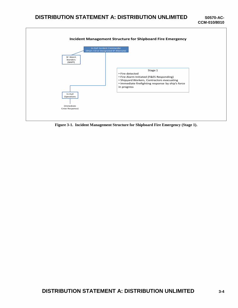
DISTRIBUTION STATEMENT A: DISTRIBUTION UNLIMITED S0570-AC-
CCM-010/8010
DISTRIBUTION STATEMENT A: DISTRIBUTION UNLIMITED 3-4
Incident Management Structure for Shipboard Fire Emergency
In-Hull
Operations
(Immediate Crew Response)
SF Watch Standers(NNPP)
Stage 1 • Fire detected• Fire Alarm Initiated (F&ES Responding) • Shipyard Workers, Contractors evacuating • Immediate firefighting response by ship’s force in progress
In-Hull Incident Commander
(Ship’s CO or Designated SF Alternate)
Figure 3-1. Incident Management Structure for Shipboard Fire Emergency (Stage 1).
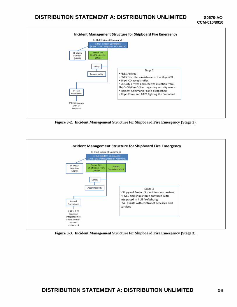
DISTRIBUTION STATEMENT A: DISTRIBUTION UNLIMITED S0570-AC-
CCM-010/8010
DISTRIBUTION STATEMENT A: DISTRIBUTION UNLIMITED 3-5
Incident Management Structure for Shipboard Fire Emergency
Senior Fire Chief/Senior Fire
Officer
In-Hull Incident Command
Safety
Accountability
In-HullOperations
(F&ES integrate with SF
Response)
SF Watch Standers(NNPP)
Stage 2• F&ES Arrives • F&ES Fire offers assistance to the Ship’s CO• Ship’s CO accepts offer.• Security arrives and receives direction from Ship’s CO/Fire Officer regarding security needs • Incident Command Post is established.• Ship’s Force and F&ES fighting the fire in hull.
In-Hull Incident Commander(Ship’s CO or Designated SF Alternate)
Figure 3-2. Incident Management Structure for Shipboard Fire Emergency (Stage 2).
Incident Management Structure for Shipboard Fire Emergency
Senior Fire Chief/Senior Fire
Officer
In-Hull Incident Command
Safety
Accountability
In-HullOperations
(F&ES & SF continue
integrated fire attack with SY
services assistance)
SF Watch Standers(NNPP)
Project Superintendent
Stage 3 • Shipyard Project Superintendent arrives.• F&ES and ship’s force continue with integrated in hull firefighting.• SY assists with control of accesses and services
In-Hull Incident Commander(Ship’s CO or Designated SF Alternate)
Figure 3-3. Incident Management Structure for Shipboard Fire Emergency (Stage 3).
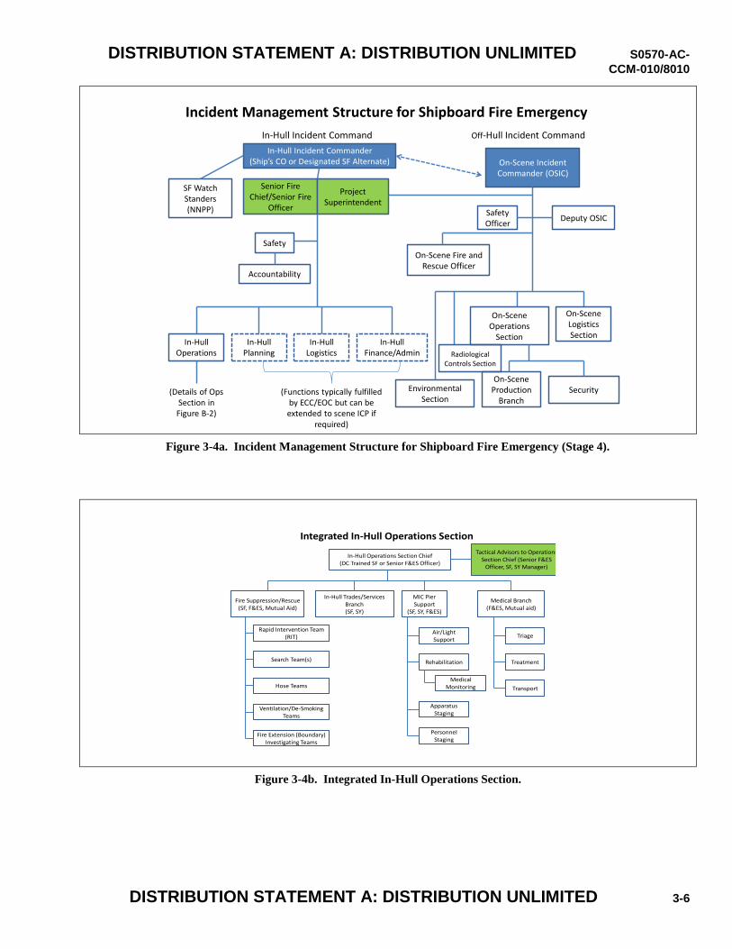
DISTRIBUTION STATEMENT A: DISTRIBUTION UNLIMITED S0570-AC-
CCM-010/8010
DISTRIBUTION STATEMENT A: DISTRIBUTION UNLIMITED 3-6
Incident Management Structure for Shipboard Fire Emergency
In-Hull Incident Commander(Ship’s CO or Designated SF Alternate)
Senior Fire Chief/Senior Fire
Officer
Project Superintendent
In-Hull Incident Command Off-Hull Incident Command
Safety
Accountability
In-HullOperations
In-HullPlanning
In-HullLogistics
In-HullFinance/Admin
(Details of Ops Section in Figure B-2)
(Functions typically fulfilled by ECC/EOC but can be extended to scene ICP if
required)
SF Watch Standers(NNPP)
On-Scene Incident Commander (OSIC)
Safety Officer
Deputy OSIC
Environmental Section
On-SceneOperations
Section
On-SceneLogisticsSection
Security
On-Scene Fire and Rescue Officer
On-Scene Production
Branch
Radiological Controls Section
Figure 3-4a. Incident Management Structure for Shipboard Fire Emergency (Stage 4).
Integrated In-Hull Operations Section
Fire Suppression/Rescue(SF, F&ES, Mutual Aid)
In-Hull Operations Section Chief(DC Trained SF or Senior F&ES Officer)
In-Hull Trades/Services Branch(SF, SY)
Medical Branch(F&ES, Mutual aid)
MIC Pier Support
(SF, SY, F&ES)
Apparatus Staging
Rehabilitation
Air/Light Support
Medical Monitoring
Personnel Staging
Triage
Transport
Treatment
Rapid Intervention Team(RIT)
Hose Teams
Search Team(s)
Ventilation/De-Smoking Teams
Fire Extension (Boundary) Investigating Teams
Tactical Advisors to Operations Section Chief (Senior F&ES
Officer, SF, SY Manager)
Figure 3-4b. Integrated In-Hull Operations Section.
DISTRIBUTION STATEMENT A: DISTRIBUTION UNLIMITED S0570-AC-
CCM-010/8010
DISTRIBUTION STATEMENT A: DISTRIBUTION UNLIMITED 3-7
3.2.3 Designation of Responsibility and Authority.
3.2.3.1 The FRP shall clearly define responsibilities and authority of SF, the F&ES Department, Mutual Aid, crews from
other ships, and the SRCA using the content of this chapter and Appendix B as a guide, which integrate SF, F&ES, and
SRCA operational requirements. Navy F&ES Departments operate in accordance with references (f) through (i). DoD
adopted the NIMS and Installation and Mutual Aid F&ES departments operate under the National Fire Protection Association
(NFPA) Incident Command System (ICS) and NIMS structure to ensure compliance with requirements of references (f), (g),
and (i). In accordance with Navy regulations, the Ship’s CO or his designated representative (e.g., Ship’s Duty Officer or
Command Duty Officer) is responsible for all actions in the ship during the emergency and thus per NIMS, is the Incident
Commander. Under the command of the Ship’s CO and as part of the Incident Command Staff, the senior F&ES Fire Chief
is expected to provide expertise and guidance for the overall response effort and along with the CO has responsibility and
authority for accountability and safety of all personnel entering the Immediately Dangerous to Life or Health (IDLH)
atmosphere (i.e., the hot zone).
3.2.3.2 The first arriving F&ES Chief/Senior F&ES Officer reports to the In-Hull Incident Commander and will integrate as
part of the in-hull incident command staff and will remain with the In-Hull Incident Commander. Further, the FRP should
specify that, the F&ES Officer will offer F&ES resources and capabilities to help combat the casualty. Once the ship accepts
assistance from F&ES with combating the casualty, the next F&ES Chief/Senior F&ES Officer will serve as the In-Hull
Operations Section Chief or assist the In-Hull Operations Section Chief as one of the Tactical Advisors. Based on the
priority dictated by the casualty situation, additional roles for senior F&ES officers, such as the On-Scene Fire and Rescue
Officer and elevation of the In-Hull Safety Officer to a senior F&ES officer, need to be filled as additional senior F&ES
officers arrive. Fire Response Plans (FRPs) and standard operating procedures should include a means to assemble the
necessary number of senior F&ES officers to staff the above roles. The In-Hull Operations Section Chief position shall be
filled by an experienced/DC trained member of SF (e.g., the DCA, Command Master Chief) or a senior F&ES officer at the
discretion of the In-Hull Incident Commander. Selection of the In-Hull Operations Section Chief by the In-Hull Incident
Commander should be based on the nature and circumstances of the casualty/response, including, but not limited to, whether
the majority of casualty responders are/will be SF or F&ES/mutual aid members. The In-Hull Operations Section Chief is
supported by Tactical Advisors which include a senior F&ES officer (if the In-Hull Operations Section Chief is SF) or an
experienced/DC trained member of SF (if the In-Hull Operations Section Chief is a senior F&ES officer) and a designated
SY manager (e.g., Deputy or Assistant PS, the Ship’s Safety Officer, Temporary Service Coordinator).
3.2.3.3 The In-Hull Operations Section is expected to assess the fire fighting equipment and personnel resources, develop
the strategy for combating the fire in order to achieve the goals/objectives established by the Incident Commander, and
provide tactical fire fighting direction, including management of all of the resources combating the fire (SF, other ship
crews, Navy F&ES, Supporting F&ES, and Mutual Aid responders), and how the resources will be integrated and
coordinated. This organization is adaptable to and consistent with the existing shipboard DC organizations on all Navy
ships. In cases where the SF Inport Emergency Team (IET) is intact and has significant capability (e.g., CVNs, LHDs),
the IET will provide the initial and likely the majority of damage control response. For these situations, the SRCA shall
develop into their FRP an IMS consistent with this chapter that integrates the response personnel from shore based fire
fighting organizations and unaffected ships into the established DC organization and command protocol. In addition, the
roles of the senior SRCA representative on the in-hull and off-hull incident command staff, the In-Hull Operations Section
and staff, as well as the On-Scene Incident Commander (OSIC) need to be defined, consistent with the radiological
emergency response organization, if applicable, and integrated with the Ship’s CO and F&ES Fire Chief to effectively
provide all required support and assistance.
3.2.4 Assignment of Designated Personnel to Specific Positions in the Emergency Response Team (ERT). This will include
initial SF responders, F&ES, members of the incident command staff, and key personnel manning the SRCA ECC and/or
EOC. For SRCAs with NPW responsibility, ERT members will be organized in such a manner as to be readily assimilated
into the shipyard’s RERO, if applicable.
3.2.4.1 The ERT organization in the ECC/EOC shall include the following Branches or Sections to support an integrated
Incident Management Structure per section 3.2.2 and as illustrated and described in appendix B for Incident Command and
Control:
a. Command
b. Logistics
c. Public Affairs
DISTRIBUTION STATEMENT A: DISTRIBUTION UNLIMITED S0570-AC-
CCM-010/8010
DISTRIBUTION STATEMENT A: DISTRIBUTION UNLIMITED 3-8
d. Engineering Technical Branch (ETB)
e. Environmental, Safety and Health Technical Branch (ESHTB)
The ETB and ESHTB will provide technical assistance to effectively fight the fire, manage the operation of temporary
services (e.g., tool service air and electrical power, etc.), temporary ship systems (e.g., breathing air, lighting, high pressure
air), and permanent ship systems in the affected areas, and coordinate environmental aspects (sampling, notifications, etc.).
Each SRCA shall incorporate these branches into their FRP and prepare operating procedures that define their duties and
responsibilities. A representative from the F&ES providing emergency response to SRCAs should be incorporated into both
branches.
3.2.4.2 For NPWs, the ETB and ESHTB supplement the branches specified in reference (d) and will use the teleconferencing
bridge telephone numbers provided in reference (j) and follow the communication practices discussed in Section 5.E of
reference (d). For non-CVN surface ships, SRCAs/RMCs shall also comply with reference (k) and shall adopt a modified
RERO for their ERT organization/Incident Command System or otherwise establish a NIMS-compliant model.
3.2.4.3 The plan shall include a method to recall ERT members and alternates, and address how to properly integrate and
coordinate SRCA ECC/EOC and Regional Operations Center (ROC)/EOC efforts.
3.2.5 Training and Integration of Fire Fighting Services. Plans and procedures shall be included to train and integrate fire
fighting and emergency medical services, Navy F&ES, SF, other ship crews, supporting F&ES, and mutual aid organizations
into the emergency response actions. This integration will include common communications systems with redundancy used
by SF, F&ES, and the incident command staff. The plan shall address the specific strategy of establishing integrated hose
teams of SF, F&ES, and mutual aid personnel early in the incident to ensure the most effective response. This arrangement
enables SF to provide technical Subject Matter Expert (SME) support and the F&ES personnel to provide interoperable
communications to enhance fire response capabilities. The FRP shall address a hose team relief process to keep hoses
staffed.
3.2.6 Personnel Accountability. Procedures for personnel evacuation and post-evacuation mustering, including non-SRCA
personnel (e.g., Alteration Installation Team (AIT) members) and reporting the muster status to Incident Command Post.
Shipboard workers shall be trained that any information about the fire and affected shipboard conditions are included in the
muster report. The plan shall also identify procedures and responsibility to account for the location and assignment of
personnel (SF, SRCA, F&ES, and mutual aid responders) taking actions to combat the casualty.
3.2.7 Response Actions. Per references (b) and (c), an in-hull ship fire can rapidly escalate to a major fire condition where it
becomes untenable for the fire fighting teams to directly fight the fire due to the effects of excessive heat and smoke.
Consequently, each SRCA’s FRP must emphasize rapidly attacking a fire with initial responders (who will normally be SF
for commissioned vessels) and then quickly integrating the installation and mutual aid firefighters per the following
requirements:
3.2.7.1 For incipient fires that have been extinguished by initial responders and do not require full response per the FRP, the
SRCAs shall ensure that FRP procedures require that these incidents are promptly reported to F&ES.
3.2.7.2 Dispatch of fire fighting resources shall be rapid, should include the resources needed based on knowledge of the
event, and shall ensure relief teams are in place when needed to relieve initial hose teams.
3.2.7.3 The FRP shall contain clear guidance on who is responsible for requesting the additional resources to include station
move up assignments and staging of additional response forces close to the ship. The plan shall also address safeguards to
preclude requesting additional resources (beyond the initial alarm) for minor events.
3.2.7.4 Utilizing appendix C that contains the attributes for an Engineered Fire Response Strategy (EFRS), the plan shall
include expected response capabilities and times for all actions by ERT personnel (SF, initial F&ES, full alarm F&ES,
additional F&ES, and mutual aid).
3.2.7.5 The FRP shall also address when the fire has escalated to a major fire requiring extended response, and thus requires
activation of the full radiological emergency response capability for NPWs. The ship’s CO (or designated representative),
senior fire chief, or SRCA leadership will determine when a fire shall be declared a major fire. In general, the fire should be
declared a major fire requiring extended response if the fire has progressed beyond the incipient stage, beyond the ability of
the initial responders (usually SF on ships in commission) to control, and is still not under control when the first hose team
outfitted in Self Contained Breathing Apparatus (SCBAs) and Fire Fighting Ensembles (FFEs) needs to be relieved. Due to
DISTRIBUTION STATEMENT A: DISTRIBUTION UNLIMITED S0570-AC-
CCM-010/8010
DISTRIBUTION STATEMENT A: DISTRIBUTION UNLIMITED 3-9
its limited compartmentalization and absence of installed fire suppression systems, a submarine fire that has spread to a
second level shall be declared a major fire. For surface ships, there may be circumstances where the fire has spread to a
second level and is under control, but in general, a multi-level spread should be considered a trip point for a major fire
declaration in surface ships as well.
3.2.7.6 Once the fire is extinguished, the FRP shall include provisions to demobilize responders that were assembled to
combat the fire.
3.2.8 Fire Fighting Doctrine. The FRP will supplement the guidelines of references (b) and (c) for fighting in port shipboard
fires in an industrial environment (e.g., control of air paths through hull cuts that feed the fire, ventilation of heat and smoke
to maintain tenable ingress/egress of personnel, how to attack a multi-level fire, management of personnel and stand-by fire
personnel, management of fire fighting water pressure/levels, etc.). The FRP shall include trip points for when to escalate the
effort (e.g., when to shift to other fire fighting agents or to activate the mutual aid response). This shall include SF casualty
procedures tailored to the SRCA environment.
3.2.9 Logistic and In-Hull Support Requirements. The FRP shall establish a process to manage immediate logistic
requirements and support to the in-hull fire fighting operations. The anticipated support required to combat a fire requiring
extended response includes: equipment, services, facilities, and materials. This shall include quantities and location of the
material and equipment and the capability to replenish those that will be expended by a major casualty. Locations may be at
the scene, on site or nearby but must be available when needed by the ERT. The FRP shall include use of an enclosed facility
to store and provide SF ready access to damage control equipment including FFEs and SCBAs. The SRCA shall ensure that
the ship’s strategy to inventory and perform maintenance of ships damage control equipment provides for ready use in the
event of emergency. The ship shall validate to the SRCA that they have conducted an inventory of damage control
equipment per applicable Navy instructions with a plan to correct any shortages that exist prior to the availability.
3.2.10 SCBA Recharge Capability. For an extended duration casualty, fire fighting resource management is optimized by
including adequate quantities of 45-minute SCBA cylinders and recharge capability. The FRP shall include the availability
of 45-minute SCBAs and the ability to recharge SCBA cylinders on scene. Cylinders may be recharged by a facility meeting
the standards of reference (l).
3.2.11 Medical Triage and Treatment. The plan shall include medical triage and treatment of injured personnel at the scene,
and transportation to medical facilities. This shall include identifying and maintaining accountability of these personnel.
3.2.12 Management of Fire Fighting Effluents. The FRP shall identify the resources necessary to dewater the ship to avoid
the weight and stability effects of an accumulation of fire fighting water. Watertight integrity shall be established to prevent
progressive flooding. In addition, the FRP shall include procedures to address environmental concerns associated with water
releases from fire fighting effluents and air emissions from the fire and smoke. Actions taken shall not delay efforts to
extinguish the fire or care for injured personnel.
3.2.12.1 During a fire event varying quantities of fire fighting water and fire suppression agents (i.e., foam, halon, and
carbon dioxide) will primarily be contained in the hull of the vessel and/or drydock. However, there may be discharge of
some of these effluents to surrounding waters. The Clean Water Act (CWA) is the primary federal law governing water
pollution and may be applicable to such discharges. The SRCA shall incorporate into their FRP any applicable requirements
of the CWA, underlying permits issued under the CWA, and the following requirements in this section. The FRP shall
include procedures for the control of fire fighting process water, suppression agents, and when in drydock, associated
drydock effluents such as non-contact cooling water, seepage water, and precipitation that may be commingled with
discharges associated with fire fighting efforts. This procedure shall include but not be limited to the following:
a. Establishment of environmental controls during the fire event to limit or prevent discharges associated with fire
fighting efforts (i.e., the use of booms, skimmers, berms, etc.).
b. Identify sampling and analytical capabilities should sampling of discharges associated with fire fighting efforts be
required. A sampling plan shall be prepared that includes sampling rationale, sample collection methods,
constituents to be sampled, analytical methods and equipment used for analysis, analytical turnaround times, and
who performs the analysis.
c. The procedures for management of discharges associated with fire fighting efforts shall include the operation of the
drydock dewatering pumps (auto vice manual operation), estimated timelines for holding of drydock water in the
confines of the drydock, use of ancillary equipment (oily water treatment systems, dissolved air floatation devices)
to treat drydock water, and routing of drydock water when discharged (sewer, holding tanks, and harbor). All such
DISTRIBUTION STATEMENT A: DISTRIBUTION UNLIMITED S0570-AC-
CCM-010/8010
DISTRIBUTION STATEMENT A: DISTRIBUTION UNLIMITED 3-10
procedures outlined in the FRP shall be coordinated with appropriate regulatory officials and be consistent with
underlying CWA permit requirements.
3.2.12.2 During a fire, three main sources of hazards are generated: heat, smoke, and depletion of oxygen; each of which
interact producing varying quantities of airborne products dependent upon characteristics such as the heat release rate,
combustible material involved (fuel source), oxygen supply, and volume of the space(s) involved. Under the authority of the
Clean Air Act (CAA) and the Emergency Planning and Community Right-to-Know Act (EPCRA), the EPA has issued
guidance addressing the hazards of these airborne products in the “Emergency Response Air Monitoring Guidance Tables”,
reference (m). In most circumstances shore-based emergency responders will respond to shipboard fires with the capability
to monitor for these airborne products. Although specialized knowledge is required to combat a shipboard fire, the airborne
products generated by a shipboard fire are not specifically unique. Unless significant quantities of known hazardous
substances (e.g., composite materials, specialized coatings, flammables, etc.) are involved or have been introduced by the
repair process, the airborne products during a shipboard fire are identified in Table 6, General Industrial Fires, of reference
(m). The SRCA shall incorporate into their FRP any applicable requirements of the CAA, underlying CAA permits, EPCRA,
and the following requirements:
a. Identify gas monitoring instrumentation available to perform air monitoring/sampling utilizing the information
contained in Table 6, General Industrial Fires, of reference (m). Instrumentation may include the following:
particulate monitors, colorimetric tubes, pH paper, portable gas chromatograph/mass spectrometer, gas detectors
with electrochemical sensor, etc.
b. Prepare an air monitoring/ sampling plan that addresses the following. The type of equipment in response kits,
response kit locations, responsible party(s) for deployment of response kits, constituents to be measured, sampling
locations and sampling intervals, analysis of sampling results.
c. Recommended actions to be implemented on-site or recommended for the public off-site (e.g., shelter in place, press
releases, evacuation, etc.) and the sample or monitoring value action level necessary to implement. Each
recommended action shall include guidance indicating when a given action is no longer required or necessary.
d. Identify plume modeling capability that is available to the shipyard for a fire event to estimate downwind
concentrations for gaseous and particulate fire byproducts. Identify weather forecasting services available to
determine real time meteorological data such as wind speed, wind direction, precipitation amounts, locations,
intensity, etc.
3.2.13 Fire Fighting Equipment. The FRP shall address systems that supplement basic fire fighting equipment (e.g., high
expansion foam systems, clean agent fire suppression systems), if these systems currently exist in the SRCA or are available
from mutual aid.
3.2.14 Technical Assistance and Coordination. The FRP shall contain a plan for coordination and technical assistance in the
techniques and procedures to deal with shipboard energized electrical systems and pressurized fluid systems, including the
management of temporary support systems and services, and actions to take with them during the casualty. The FRP shall
address methods to sustain onboard life-safety systems (e.g., breathing air for remaining shipboard watch-standers). SF and
SRCA personnel shall be prepared to seal hull openings with staged material to control available oxygen to the fire and
control temporary ventilation systems and flow paths to support tenable access/egress of personnel and de-smoking of spaces.
3.2.15 Extended Operations Plan. The plan shall include response (shift coverage) for extended operations that will last
more than several hours, including identification of the means to recall off-duty personnel.
3.2.16 Ship Conditions. The FRP shall address changing ship conditions during the various stages of a ship’s construction or
maintenance: Waterborne or in drydock, in-hull and drydock basin, access changes due to variations in hull access cuts,
staging, hatch accessibility, submarine protective shelters, conditions below decks, etc.
3.2.17 Reporting Procedures. The FRP shall include procedures for implementing Navy Operational Reporting (OPREP)
requirements and communications procedures with Naval Command Activities including: NAVSEA, TYCOM, Fleet, Navy
Region, and CNIC. If applicable, once reference (e) becomes the governing instruction, OPREP procedures shall be per
references (d) and (e).
DISTRIBUTION STATEMENT A: DISTRIBUTION UNLIMITED S0570-AC-
CCM-010/8010
DISTRIBUTION STATEMENT A: DISTRIBUTION UNLIMITED 3-11
3.2.18 Procedures for Liaison with Civil Authorities.
3.2.18.1 For major shipboard fires aboard NPWs, liaison with Federal, State, and local officials will be conducted consistent
with the procedures and requirements of reference (d), if applicable. Prior to reference (e) being invoked, communications
with State and local authorities shall be coordinated between the cognizant Navy Region EOC/ROC and affected SRCA.
3.2.18.2 For major fires aboard non-NPWs, each NSA, in conjunction with the cognizant Type and Fleet Commanders, shall
have procedures and equipment in place and personnel assigned to notify and communicate with civil authorities per the
following guidance.
a. State and Local authorities are responsible for the management of off-site activities and for the protection of the
public during any emergency that affects public safety or health, regardless of the source. To assist these
authorities in executing their duties, each NSA shall include in their FRP the 24-hour civil authority emergency
management personnel points of contact with their office and home/cellular phone numbers.
b. Initial notification. The timing of initial notification as well as the level and seniority of personnel notified (i.e.,
Local vs. State, Fire Chief vs. City Mayor, State EMO vs. Governor) shall be governed by the scope of the
casualty.
c. Consistency of protection recommendations. It is important to establish and maintain a consistency relative to
off-site personnel protection recommendations made to civil authorities and those actions that are being taken
on the site. For example, if on-site shelter-in-place actions are being taken for personnel affected by the fire,
then recommendations for similar protection for off-site personnel should be made unless there is valid
technical basis for not doing so. This information shall be shared with the civil authorities.
d. Communications with cognizant Federal Agencies. Notification and follow-up communications with other
federal agencies such as the EPA and FEMA will be determined by and the responsibility of NAVSEA in
consultation with CNIC and the cognizant Fleet Commander. The SRCA shall provide notifications to regional
EPA and FEMA offices, where applicable, after discussions with NAVSEA Headquarters and ROC/EOC
command personnel. If regional federal offices are to be notified, they will be done only after notifying state
and local officials of the major fire.
e. Media notification. Prior to release of any information to the media, the initial notification shall be made to
civil authorities per section 3.2.18.2. These authorities shall be kept appraised of any planned media
notification such as a press release, media availability or press conference. The NSA, in conjunction with the
cognizant Type and Fleet Commanders, shall ensure the information is provided to civil authorities prior to a
press release and extend an invitation to civil authorities to be present or participate at any press availability.
3.2.19 Public Affairs. The FRP shall include procedures for the release of information to the public (press releases, press
conference/availability, etc.). For major fires in NPWs, release of public information shall be conducted consistent with the
requirements and procedures of reference (e). Prior to reference (e) being invoked for NPWs, public releases shall be
coordinated between the cognizant Navy Region EOC/ROC, NAVSEA 08, and affected SRCA.
3.2.20 Accident Information Collection and Storage. The FRP shall include provisions to assemble and store information
generated during an accident to enable an accurate reconstruction of the event for review by senior officials and public
notification. All fires shall be investigated. When invoked, references (n) and (o) shall be used. In conjunction with this
investigation or separately, the SRCA shall lead an ERT debrief to evaluate the effectiveness of the fire response actions and
take corrective action to improve the FRP, including ERT training.
3.2.21 Roles and Responsibilities of Activities. Where a SRCA relies upon and/or interacts with other Activity Emergency
Operations Centers, the FRP shall include the roles and responsibilities of the government, region, and base emergency
operations (where applicable) centers or refer to these procedures that define these duties.
3.3 TRAINING.
3.3.1 F&ES Training. Navy F&ES departments and crews that respond to initial alarms to shipboard fires where ships are in
industrial availabilities shall conduct training sessions to improve proficiency, familiarity, and knowledge of common
terminology with shipboard spaces that will enhance the ability to fight a shipboard fire.
3.3.1.1 Navy F&ES personnel designated to respond to or support shipboard fire fighting shall be trained in accordance with
the F&ES department’s training plan. The training plan will leverage training from the SRCA and SF in conducting
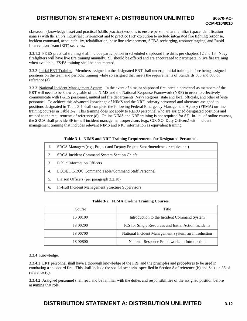
DISTRIBUTION STATEMENT A: DISTRIBUTION UNLIMITED S0570-AC-
CCM-010/8010
DISTRIBUTION STATEMENT A: DISTRIBUTION UNLIMITED 3-12
classroom (knowledge base) and practical (skills practice) sessions to ensure personnel are familiar (space identification
names) with the ship’s industrial environment and to practice FRP execution to include integrated fire fighting response,
incident command, accountability, rehabilitation, hose line advancement, SCBA recharging, resource staging, and Rapid
Intervention Team (RIT) searches.
3.3.1.2 F&ES practical training shall include participation in scheduled shipboard fire drills per chapters 12 and 13. Navy
firefighters will have live fire training annually. SF should be offered and are encouraged to participate in live fire training
when available. F&ES training shall be documented.
3.3.2 Initial ERT Training. Members assigned to the designated ERT shall undergo initial training before being assigned
positions on the team and periodic training while so assigned that meets the requirements of Standards 505 and 508 of
reference (a).
3.3.3 National Incident Management System. In the event of a major shipboard fire, certain personnel as members of the
ERT will need to be knowledgeable of the NIMS and the National Response Framework (NRF) in order to effectively
communicate with F&ES personnel, mutual aid fire departments, Navy Regions, state and local officials, and other off-site
personnel. To achieve this advanced knowledge of NIMS and the NRF, primary personnel and alternates assigned to
positions designated in Table 3-1 shall complete the following Federal Emergency Management Agency (FEMA) on-line
training courses in Table 3-2. This training does not apply to RERO personnel who are assigned designated positions and
trained to the requirements of reference (d). Online NIMS and NRF training is not required for SF. In-lieu of online courses,
the SRCA shall provide SF in-hull incident management supervisors (e.g., CO, XO, Duty Officers) with incident
management training that includes relevant NIMS and NRF information as equivalent training.
Table 3-1. NIMS and NRF Training Requirements for Designated Personnel.
1. SRCA Managers (e.g., Project and Deputy Project Superintendents or equivalent)
2. SRCA Incident Command System Section Chiefs
3. Public Information Officers
4. ECC/EOC/ROC Command Table/Command Staff Personnel
5. Liaison Officers (per paragraph 3.2.18)
6. In-Hull Incident Management Structure Supervisors
Table 3-2. FEMA On-line Training Courses.
Course Title
IS 00100 Introduction to the Incident Command System
IS 00200 ICS for Single Resources and Initial Action Incidents
IS 00700 National Incident Management System, an Introduction
IS 00800 National Response Framework, an Introduction
3.3.4 Knowledge.
3.3.4.1 ERT personnel shall have a thorough knowledge of the FRP and the principles and procedures to be used in
combating a shipboard fire. This shall include the special scenarios specified in Section 8 of reference (b) and Section 36 of
reference (c).
3.3.4.2 Assigned personnel shall read and be familiar with the duties and responsibilities of the assigned position before
assuming that role.
DISTRIBUTION STATEMENT A: DISTRIBUTION UNLIMITED S0570-AC-
CCM-010/8010
DISTRIBUTION STATEMENT A: DISTRIBUTION UNLIMITED 3-13
3.3.5 Practical Abilities. Personnel knowledge and demonstration of practical abilities shall be demonstrated during training
sessions or functional area drills. This shall include the plan’s Fire Fighting Principles and EFRS of appendices A and C.
3.3.6 Re-verification.
3.3.6.1 All personnel assigned to ERT positions shall be re-verified for this assignment by repeating the knowledge and
practical abilities of paragraphs 3.3.3 and 3.3.4 or by validation of regular participation in the emergency response continuing
training program. The periodicity of these training requirements shall be established by each SRCA and installation
command, shall be compliant to the requirements of reference (a), and shall include as a minimum, quarterly training on the
applicable emergency response procedures and participation in the fire drills per the frequency established in chapters 12 and
13 of this manual.
3.3.6.2 Installation firefighters at SRCAs and those firefighters designated as initial responders, shall receive annual live fire
training per references (p) and (q).
3.3.7 Mutual Aid Agreements. SRCAs should work through the Navy F&ES department when a mutual aid agreement is in
place and required to support the FRP. At SRCA locations requiring civilian fire department support to execute the FRP, the
SRCA shall enter into appropriate agreements. The SRCA shall approve classroom/practical shipboard firefighter
familiarization training for mutual aid civilian departments.
3.4 RAPID RESPONSE DAMAGE CONTROL CONEX BOX, SUBMARINES. The NSA shall ensure each SRCA
implements the following requirements to improve response to a major fire in submarines undergoing availabilities. Actions
apply to all commissioned submarines in CNO schedule availabilities.
3.4.1 Damage Control (DC) Equipment. Each availability shall have a dedicated set of the DC equipment listed in appendix
D as required by this manual.
3.4.2 Storage of DC Equipment. The DC equipment shall be staged in a “locker” on the pier adjacent to the brow to provide
for a rapid response by SF in the event of an emergency. The Rapid Response DC CONEX box portrayed in appendix D is
intended to serve as this locker. This locker shall be the stowage location for all DC equipment required for casualty
response for the duration of the availability and shall be incorporated into the SRCA FRP.
3.4.3 Custody of DC Equipment. The SRCA shall enter into an agreement with the ship to turn over custody of the DC
equipment provided to the ship for the duration of the availability. The ship will relinquish custody at the conclusion of the
availability. “Custody” includes responsibility for periodic maintenance of the equipment. Maintenance requirements cards
for equipment not included in the ship’s on board allowance will be provided by the SRCA. The SRCA will maintain
responsibility to procure and/or replace material if required.
3.4.4 Alternate Storage Location. The SRCA shall provide an alternate storage location for SF DC equipment removed from
the ship during the availability. The storage location shall be within close proximity to the ship.
3.4.5 Staging of DC Equipment. To optimize deployment of SF DC personnel and to allow efficient SF and F&ES
firefighter integration, the augmented DC equipment shall be staged near the ship and in the CONEX box(es) also used to
stage their normal DC equipment when removed from the ship due to industrial work. These storage boxes shall be equipped
with lighting, heat, and air conditioning systems to facilitate DC gear breakout during the casualty and to maintain the gear
within normal ambient temperature ranges.
3.4.6 Accessibility of DC Equipment. The DC CONEX box and equipment shall be available to the crew upon entering
drydock or before the ship’s DC equipment is removed from the ship. When hot work is needed prior to the ship being
provided the CONEX box and augmented gear, a mitigation plan to ensure the ship’s fire response is adequate shall be
approved by the FSC.
3.4.7 Transition to Habitability. The additional DC equipment and CONEX storage box is no longer required once the
habitability key event (HB00) is attained. Under these ship conditions, the crew has moved back on board and most
industrial hot work has been completed. Normal DC equipment must be installed and operational. Disestablishing the
requirement shall be approved by the FSC.
DISTRIBUTION STATEMENT A: DISTRIBUTION UNLIMITED S0570-AC-
CCM-010/8010
DISTRIBUTION STATEMENT A: DISTRIBUTION UNLIMITED 3-14
3.5 FIRE LANES. In accordance with references (r) and (s), and (t) for Navy facilities, fire lanes shall be designated and
identified adjacent to ships pier side, dockside while in drydock, or on building ways to provide access for emergency
apparatus.
3.5.1 Fire Lane Width. Fire lanes intended for one-way travel shall provide a minimum of 16 ft (5 m) in width of traveled
way. Fire lanes providing two-way travel shall be a minimum of 24 ft (7.3 m) in width of traveled way.
3.5.2 Vertical Clearance. At least 13 ft 6 in. (4.2 m) nominal vertical clearance shall be provided and maintained over the
full width of a fire lane.
3.5.3 Angle of Approach/Departure. The angle of approach and the angle of departure shall not exceed 8 degrees at any
point on the fire lane or its intersection with other roads or fire lanes. Minimum inside turn radius shall be 25 ft and
minimum outside turn radius shall be 50 ft.
3.5.4 Wintertime Maintenance. A plan for wintertime maintenance of access through any gates and along any fire lane shall
be submitted to the responsible fire department.
3.5.5 Fire Lane Markings. Fire lanes shall be marked/identified in accordance with the instructions of the fire department
having responsibility, and reference (u) for Navy facilities, and a method of enforcing such provisions shall be provided.
3.5.6 Waiver Request. Due to existing infrastructure, some requirements of this section may not be achievable in the
timeframe of manual implementation. In those cases, the SRCA should submit a waiver request to NAVSEA citing the
specific conditions that require a waiver and include an estimate for the cost and time necessary to achieve compliance.
3.5.7 Approval to Temporarily Block a Fire Lane. When facilities work projects or other situations require a fire lane to be
temporarily blocked, the FSC and Fire Chief shall approve the project in advance.
DISTRIBUTION STATEMENT A: DISTRIBUTION UNLIMITED S0570-AC-
CCM-010/8010
DISTRIBUTION STATEMENT A: DISTRIBUTION UNLIMITED 4-1
Chapter 4 HOT WORK AND FIRE WATCH
References
(a) S9086-CH-STM-010, Naval Ships’ Technical Manual (NSTM) Chapter 074, Volume 1, Welding and Allied Processes
(b) S6470-AA-SAF-010, Naval Maritime Confined Space Manual
(c) Occupational Safety and Health Standards for Shipyard Employment, 29 CFR Part 1915 Subpart P, Fire Protection in
Shipyard Employment
(d) National Fire Protection Association (NFPA) Codes and Standards 51B, Standard for Fire Prevention During Welding,
Cutting, and Other Hot Work
(e) National Fire Protection Association (NFPA) Codes and Standards 312, Standard for Fire Protection of Vessels During
Construction, Conversion, Repair, and Lay-up
(f) National Fire Protection Association (NFPA) Codes and Standards 306, Standard for the Control of Gas Hazards on
Vessels
(g) Occupational Safety and Health Standards for Shipyard Employment, 29 CFR Part 1915 Subpart B, Confined and
Enclosed Spaces and Other Dangerous Atmospheres in Shipyard Employment
(h) NAVSEA OP 4, Ammunition and Explosives Safety Afloat
Introduction
In accordance with the hot work requirements of references (a) through (c), this chapter implements the necessary
precautions, procedures, and safety requirements as related to hot work operations during an industrial availability. This
chapter applies to all SRCAs (except new construction shipyards) and covers all Navy ships – submarines, surface ships, and
aircraft carriers.
The very existence of hot work operations in an industrial environment poses an increased risk to SF and SRCA workers,
justifying the need for additional fire watches and fire extinguishers, in parallel with the combustible loading requirements
contained in chapter 5 of this manual. Flexibilities are built into the fire watch requirements contained here-in to ensure
proper visible coverage of hot work operations by minimal personnel. In implementation of these requirements, it is
important to note that the prevention and early detection of a small fire is the most effective means of preventing a major
shipboard fire.
4.1 HOT WORK MEMORANDUM OF AGREEMENT.
4.1.1 Classifications of Hot Work. Consistent with references (a) and (b), hot work includes the following operations:
a. Flame heating, welding, torch cutting, brazing, and carbon arc gouging.
b. Work which produces heat, by any means, of 400 °F (204 °C), or more.
c. Grinding, drilling, abrasive blasting, or similar spark-producing operations EXCEPT when such operations are
isolated physically from any atmosphere containing 10 percent or greater of the Lower Explosive Limit of a
flammable or combustible substance.
4.1.2 Hot Work MOA. Prior to performing hot work during an availability, the NSA shall ensure that a Memorandum of
Agreement (MOA) is in place with the ship to cover the hot work notification process. The ship shall be notified in advance
of hot work, and status of hot work jobs shall be kept up to date at least daily. The following shall be considered with regards
to the MOA:
a. The NSA shall ensure that all hot work performed by all maintenance and modernization activities during the
availability is coordinated through the LMA.
DISTRIBUTION STATEMENT A: DISTRIBUTION UNLIMITED S0570-AC-
CCM-010/8010
DISTRIBUTION STATEMENT A: DISTRIBUTION UNLIMITED 4-2
b. For hot work performed outside of an availability with an assigned NSA, the SRCA will establish a MOA(s)
between the ship and all outside activities performing hot work.
4.2 HOT WORK AUTHORIZATION.
4.2.1 Written Notice. As required per reference (c), hot work shall only be conducted after a written notice for each job or
separate area of hot work aboard ship is provided and a fire watch posted. The written notice shall include the following
attributes:
a. State a description of the work to be done.
b. List the specific location of the hot work to include compartment number and the compartment numbers of adjacent
decks, bulkheads and similar structures upon which hot work is to be accomplished.
c. State the time hot work will commence.
d. List the current gas-free status of the area.
e. List the absence or existence of combustible material within 35 feet of the operation (or further if affected by the
operation), and if combustible material exists, the action taken to protect the material from fire.
f. State the provision and assignment of a fire watch.
g. Affirm that conditions at work site (ventilation, temporary lighting, and accesses) permit the fire watch(es) to have a
clear view of and immediate access to all areas included in the fire watch.
h. Affirm that a suitable fully charged fire extinguisher is available at the job site.
i. Provide for an inspection of the area 30 minutes after completion of the hot work or the cessation of hot work at the
job site as the final action to complete the notice. If after 30 minutes the job site is not cool to the touch, do not
leave the job site, and notify the nearest watch-stander/manager. When strip heaters are in use for post weld heat
treatment, the fire watch shall remain in the hot work area for at least 30 minutes after completion of the welding,
and shall survey the exposed area(s), and make a determination that there is no further fire hazard prior to
completing the notice and leaving the area.
4.2.2 Signing Authority. The notice shall be signed by a supervisor specifically designated as responsible for coordination of
the hot work and the fire watch requirement.
4.2.3 Posting of Notice. One copy of each notice shall be conspicuously posted at the location where the hot work is being
accomplished, and the Commanding Officer’s designated representative shall be notified of all areas where hot work is being
performed.
4.2.4 Notice to the CO’s Representative. The notice to the Commanding Officer’s designated representative shall precede
the initiation of the actual hot work in order to permit the Commanding Officer to designate a member of the crew to observe
the operation, if desired.
4.3 GAS-FREE PROCEDURES AND SPECIAL HAZARDS.
4.3.1 Governance for Gas Free Procedures. The Navy Maritime Confined Space Program shall be the governing authority
for gas-free procedures. All gas-free procedures shall be in accordance with references (d) through (f).
4.3.1.1 For Naval activities, gas-free procedures shall also be in accordance with reference (b).
4.3.1.2 For contractor activities, gas-free procedures shall also be in accordance with reference (g).
4.3.2 Restricted Areas for Hot Work. Hot work shall not be conducted in closed or poorly ventilated spaces as defined in
reference (b), subject to the risk of fire, explosion, exposure to toxic substances, or suffocation or asphyxiation, until
appropriate test and procedures have been conducted in accordance with references (b) and (c).
4.3.3 Coverings. Fire-resistant coverings meeting the requirements of chapter 5 of this manual shall be secured in place
prior to commencing hot work to adequately protect piping and equipment.
4.3.4 Lines/Piping Containing Flammable or Combustible Fluids. Lines/piping containing flammable and/or combustible
fluids shall be depressurized and protected from damage/heat while conducting welding or hot work operations adjacent to
these lines/pipes.
DISTRIBUTION STATEMENT A: DISTRIBUTION UNLIMITED S0570-AC-
CCM-010/8010
DISTRIBUTION STATEMENT A: DISTRIBUTION UNLIMITED 4-3
4.3.5 Proximity of Flammables and Combustibles. Consistent with references (a) and (c), where practicable relocate all
flammables and combustibles at least 35 feet from hot work operations to prevent the spread of fire unless the requirements
of paragraph 4.1.1.(c) are met. Where relocation is impracticable, protect combustibles with metal or guards and curtains
constructed of material meeting the requirements of sections 5.1.3.1 or 5.1.3.2.
4.3.6 Ammunition or Explosives. Hot work operations in or adjacent to areas containing ammunition or explosive material
or substance shall be conducted in accordance with reference (h).
4.3.6.1 Hot work shall not be conducted during any logistics or maintenance movement of ammunition or explosives.
4.3.6.2 Hot work shall not be conducted during any fueling operations without approval by the FSC and risk mitigation
implemented.
4.3.7 Battery Charging Operations. The following precautions shall be employed during battery charging operations:
a. Care taken to prevent accidental sparking of electrical apparatus.
b. Suspension of hot work except for submarines which have the Submarine Valve Regulated Lead Acid (SVRLA)
battery that have ventilation and atmospheric control equipment lined up in accordance with the class Ship Systems
Manual and the battery is being operated in accordance with the appropriate SVRLA battery technical manual.
4.3.8 Additional Precautions. Necessary safety precautions shall be taken prior to conducting hot work on tanks, piping
systems, or components which have previously contained flammable liquids. This includes hot work operations within 35
feet of tanks or piping that contain or previously contained flammable liquids in accordance with reference (b).
4.4 FIRE WATCH REQUIREMENTS AND TRAINING.
4.4.1 Fire Watch Policy. Each SRCA shall create and maintain a written fire watch policy meeting the requirements of
reference (c). Personnel, including SF, performing hot work and/or hot work watch standing shall undergo a training
program that covers their specific responsibilities in accordance with reference (c).
4.4.2 Additional Duties During Hot Work. The fire watch shall not accomplish other duties while hot work is in progress.
4.4.3 Limitations to Single Fire Watch with Multiple Hot Workers. A single fire watch may provide protection where
several hot workers are performing hot work in a single work area with the following limitations:
a. The fire watch must have an unobstructed view, without turning, of all hot work operations and exposed areas from
a single fixed location at which he is stationed and have no physical obstructions or barriers that would prevent
immediate access by the fire watch to the hot work operation should a fire occur.
b. No more than four hot workers shall be attended by a single fire watch.
c. The fire watch cannot rove from one compartment/area to another in carrying out their duties as a fire watch in a
way which would affect the requirement of maintaining a continuous line of sight view of all hot work.
d. A means of communicating between the fire watch and all hot workers shall be provided such that in the event of a
fire, the fire watch can immediately notify all hot workers to stop operations.
4.4.4 Hot Work Involving Multiple Levels. In cases in which hot material from hot work may involve more than one level,
as in trunks, machinery spaces, and on scaffolding, a fire watch shall be stationed at each level unless positive means are
available to prevent the spread or fall of hot material.
4.4.5 Bulkhead or Deck Hot Work. In cases where hot work is to be accomplished on a bulkhead or deck, combustible
material shall be removed from the vicinity of the hot work on the opposite side of the bulkhead, overhead, or deck, and a fire
watch shall be posted at each location.
4.4.6 Blind Compartment Hot Work. If multiple blind compartments are involved in any hot work job, fire watches shall be
posted simultaneously in each blind area.
4.4.7 Communication Between Fire Watches. When more than one fire watch is required, a communication means between
the fire watches shall be established.
DISTRIBUTION STATEMENT A: DISTRIBUTION UNLIMITED S0570-AC-
CCM-010/8010
DISTRIBUTION STATEMENT A: DISTRIBUTION UNLIMITED 4-4
4.4.8 Fire Extinguishers. Fire extinguishers used for hot work shall be provided by the performing activity and shall not be a
ship’s installed extinguisher.
4.4.9 Fire Watch Training. All fire watches shall undergo a training program in accordance with references (a) and (c) that
covers, at a minimum, their responsibilities, use of fire extinguishing and other required safety equipment, inspection of
immediate and surrounding areas before, during, and after hot work, assigned station during actual hot work, method of
communication between fire watch and hot work operator, the appropriate reporting procedure for a fire while assigned as a
fire watch and the sounding of fire alarms.
DISTRIBUTION STATEMENT A: DISTRIBUTION UNLIMITED S0570-AC-
CCM-010/8010
DISTRIBUTION STATEMENT A: DISTRIBUTION UNLIMITED 5-1
Chapter 5 INDUSTRIAL MATERIALS USED AND STORED SHIPBOARD
References
(a) S9AA0-AB-GOS-010, General Overhaul Specifications For Overhaul of Surface Ships (GSO)
(b) S0902-018-2010, General Overhaul Specifications For Deep Diving SSBN/SSN Submarines (DDGOS)
(c) Occupational Safety and Health Standards for Shipyard Employment, 29 CFR Part 1915 Subpart P, Fire Protection in
Shipyard Employment
(d) National Fire Protection Association (NFPA) Codes and Standards 30, Flammable and Combustible Liquids Code
(e) S9086-WK-STM-020, Naval Ships’ Technical Manual (NSTM) Chapter 670 Stowage, Handling, and Disposal of
Hazardous General Use Consumables, Volume 1, Afloat Hazardous Material Control and Management Guidelines
(f) S9086-WK-STM-020, Naval Ships’ Technical Manual (NSTM) Chapter 670, Volume 2, Afloat Hazardous Material
Control and Management Guidelines Hazardous Materials User Guide (HMUG)
(g) MIL-STD-1623, Fire Performance Requirements and Approved Specifications for Interior Finish Materials and
Furnishings (Naval Shipboard Use)
(h) National Fire Protection Association (NFPA) Codes and Standards 701, Standard Methods of Fire Tests for Flame
Propagation of Textiles and Films
(i) MIL-C-24576, Military Specification: Cloth, Silica Glass, Cloth, Coated, Glass, Silicone Rubber Coated
(j) American Society for Testing and Materials (ASTM) Standard D6413, Standard Test Method for Flame Resistance of
Textiles (Vertical Test)
(k) MIL-L-19140, Military Specification: Lumber and Plywood, Fire Retardant Treated
(l) S9086-KC-STM-010, Naval Ships’ Technical Manual (NSTM) Chapter 300, Electric Plan – General
(m) NAVSEA 0989-043-0000, Commissioned Surface Ship General Reactor Plant Overhaul and Repair Specification
(n) NAVSEA OP 4, Ammunition and Explosives Safety Afloat
Introduction
This chapter provides requirements for the stowage and protection of combustible materials used shipboard during industrial
work. This chapter applies to all SRCAs and covers all Navy ships – submarines, surface ships, and aircraft carriers. These
sections were developed largely from existing requirements in references (a) and (b), satisfy the cognizant requirements in
reference (c), and incorporate new requirements to minimize the amount of combustible material brought onboard by the
industrial activity and to ensure it is properly protected. The importance of these requirements stems from the scope and
amount of industrial work that is performed onboard Navy ships and submarines during a maintenance availability, as well as
the increased risk for a shipboard fire to spread rapidly during an availability in comparison to at sea conditions. Many of the
ship’s permanent fire fighting systems are secured during an industrial availability, requiring the installation of similar
temporary fire fighting systems. The ship condition also potentially compounds the risk of fire ignition and spread. All these
factors combined make it crucial to properly control the combustible materials brought and used onboard.
The chapter does provide some flexibility in how the requirements are met. For example, temporary structures with closed
overheads and open sides installed in ship hangar bays can be protected with temporary sprinkler systems or configured so
they can be adequately protected with fire hoses. These flexibilities and others will allow the SRCAs to adapt the
requirements to meet the availability requirements in a safe and cost effective manner.
DISTRIBUTION STATEMENT A: DISTRIBUTION UNLIMITED S0570-AC-
CCM-010/8010
DISTRIBUTION STATEMENT A: DISTRIBUTION UNLIMITED 5-2
In addition, section 5.4 of this chapter provides requirements for fire prevention and safety inspections on each project, in
alignment with required inspections per reference (c). These inspections are intended to identify and remove fire safety
hazards, as well as provide the FSC with appropriate cognizance over the ship status to mitigate the risks inherent to
maintenance availabilities. It is impossible to remove all of the risk associated with industrial shipboard work, but
appropriate steps need to be taken to mitigate the risks in balance with cost and schedule concerns, and ensure the safety of
the ship and all personnel working shipboard.
5.1 FLAMMABLE AND COMBUSTIBLE MATERIAL.
5.1.1 Materials Used Shipboard By Maintenance Activities. A combustible material is a material that, in the form in which
it is used and under the conditions anticipated, will ignite and burn; a material that does not meet the definition of non-
combustible or limited-combustible; or any liquid that has a closed cup flash point at or above 100 °F, as determined by
reference (d). The following is a list of items that are routinely used by maintenance activities that, unless specifically
treated, are combustible or flammable. This list is not all inclusive, but serves as a reminder that many of the supplies and
tools used by maintenance activities are combustible or flammable.
a. String/rope (for lines and leads, slings for equipment support/rigging).
b. Compressed gases tanks/containers (propane, aerosols).
c. Cleaning products (petroleum based distillates).
d. Lubricants (petroleum hydrocarbons, i.e., oil and grease).
e. Rubber products (electrical insulation, vibration reduction, gaskets).
f Paints/thinners/strippers (aromatic hydrocarbon thinners in uncured form).
g Adhesive/adhesive removers (alcohols in uncured form).
h Containments (shop tool bag, various size plastic bags, containers, and sheets).
i Bottles (plastic collecting, material transport, and sampling).
j Plastic bodied tools/equipment (vacuum cleaners, hand tools).
k Batteries (flammable and various toxic chemicals).
l. Personal Protective Equipment (PPE) (disposable tank suits, hard hats, gloves).
m. Cellulose based products (kimwipe or like material, paper, folders for work packages).
n. Wood structures (ladders, staging, temp decking, temporary enclosures).
o. Hydraulic fluids.
p. Power extension cords and cables.
q. Absorbent booms/pigs used for fuel spill clean-up.
5.1.2 Consumable Materials. Consumable materials (e.g., kimwipes or like material, rags, greases, paint, solvents, etc.) in
use at a work site shall be limited to a quantity that will cover one shifts work or sufficient to complete the job, whichever is
smaller. Hazardous materials brought to the worksite shall be kept in approved containers and handled in accordance with
references (e) and (f). Unused quantities shall be removed from the ship immediately and returned for reissue or disposal as
appropriate. Soiled rags, paper, or other oil soaked articles shall be removed immediately following clean up, or may be
collected in approved metal receptacles. Receptacles shall be emptied at the end of each shift.
5.1.2.1 For ships without large temporary shipboard stowage locations, small quantities (e.g., several days’ worth) of
combustible cleaning materials (kimwipes or like material, rags, small cleaning buckets) may be centrally stored onboard in
small quantities in approved metal containers. A portable extinguishing agent (e.g., CO2 bottle) shall be staged with these
stowage containers. For commissioned ships, the stowage plan shall be agreed to by the ship’s Commanding Officer.
5.1.2.2 This guidance does not apply to pre-staged hazardous material emergency spill kits.
DISTRIBUTION STATEMENT A: DISTRIBUTION UNLIMITED S0570-AC-
CCM-010/8010
DISTRIBUTION STATEMENT A: DISTRIBUTION UNLIMITED 5-3
5.1.3 Fire Resistant Materials.
5.1.3.1 Non-fabric material used in hull for containment or as protective coverings for equipment, decking, and furnishings
shall be in accordance with reference (g). Fabrics used in hull for containment or as protective coverings for equipment,
decking, and furnishings shall be tested in accordance with and meet the requirements of reference (h) or be listed as an
acceptable "Drapery or Curtain" in reference (g). Flame-resistant material shall be marked with symbol "FR".
5.1.3.2 Fireproof or fire-resistant covering such as fireproofed canvas, fire-resistant synthetic fabrics, noncombustible
fabrics, metal covers, or other suitable materials, shall be used to protect intricate and vulnerable items of machinery and
equipment from falling sparks or other potential sources of fire. Materials other than meeting the requirements of reference
(i) or metal covers shall be tested in accordance with reference (j) and demonstrate the following performance: maximum
char length of 1.5 inches, maximum after flame of 1 second, maximum afterglow of 2 seconds, and not exhibit any molten or
flaming droplets. Coverings shall be secured in place prior to commencing hot work to provide adequate protection.
Asbestos and materials containing asbestos shall not be used.
5.1.3.3 Use of lumber plywood products shipboard to support work shall be minimized. When required, lumber products
shall be fire retardant in accordance with reference (k), Type II, Category 2. Manufacturers’ markings shall remain visible at
all times, unless wrapped by “FR” material. Lumber plywood that has become worn due to placement in heavy traffic areas
or exposure to weather shall not be reused.
5.1.3.4 Temporary ventilation ducts that support hot work (at a minimum), both supply and exhaust, shall be fire resistant.
Manufacturer’s markings on the duct, "FR" or "Fire Resistant", shall be visible on each installed duct segment.
5.1.3.5 This guidance does not apply to currently regulated and controlled radiological containments, nor does it supersede
any requirements of the Naval Nuclear Propulsion Program.
5.1.4 Plastic Trash Cans. Outside Activity (OA) plastic trash cans are prohibited in hull in affected spaces where industrial
work is being performed for trash collection. Plastic trash bags may be used in hull as a liner for a metal trash can.
5.1.5 Plastic Bodied Tools. Plastic bodied tools and equipment may be stowed onboard, provided that they are stowed in
metal tool boxes or stored in designated storage areas per paragraph 5.3.4, otherwise, they shall be removed at the end of each
shift. Equipment that must remain in service after working hours (e.g., temporary lighting, poly bottles, monitoring devices,
etc.) is exempt from this requirement.
5.1.6 Metal Canister Vacuum Cleaners.
5.1.6.1 All OA vacuum cleaners used shipboard shall have metal canisters. This includes those used for post hot work clean
up.
5.1.6.2 OA plastic canister vacuum cleaners may still be employed for general housekeeping off-hull in shops, drydocks, and
work areas.
5.1.6.3 The use of metal canister vacuum cleaners shall comply with the requirements of reference (l).
5.1.6.4 This guidance does not apply to currently regulated and controlled radiological and Hazmat/Hazwaste vacuum
cleaners nor does it supersede any requirements of the Naval Nuclear Propulsion Program.
5.1.7 Smoking Policies. NSA shall ensure compliance with SRCA smoking policies. Where SRCA policies allow smoking
shipboard (large decks), it shall be restricted to designated areas on the weather deck. Shipboard smoking areas shall be
approved by the NSA with concurrence from the ship’s CO for commissioned vessels.
5.1.8 Flammable Compressed Gas Cylinders. Flammable compressed gas cylinders placed aboard ship shall be minimized.
When circumstances allow, locate supply on the pier and furnish gases from a header to manifolds on the ship. When gas
cylinders are required to be placed aboard ship, limit the number to those actually being used and rigged with gages and hose.
In order to allow personnel to replenish their gas supply, additional gas cylinders, not to exceed one-half the number of in-use
cylinders, may be located in a remote area on the ship’s weather decks.
5.1.9 Flammable and Combustible Liquid Stowage. The quantity of flammable and combustible liquids, such as paints and
lubricants brought to the work site, shall be kept to a minimum and shall not exceed that necessary for one shift’s use.
Appropriate fire extinguishing equipment (Class B) shall be located in the vicinity of these limited quantities. Unused
DISTRIBUTION STATEMENT A: DISTRIBUTION UNLIMITED S0570-AC-
CCM-010/8010
DISTRIBUTION STATEMENT A: DISTRIBUTION UNLIMITED 5-4
flammable and combustible liquids shall be removed from the ship at the end of the work day and stowed in a suitable shore
storage facility.
5.1.10 Combustible Materials and Waste. The ship and surrounding areas shall be maintained in a neat and orderly
condition. All waste material shall be collected and removed as it accumulates. Packaged material, other than that scheduled
for immediate use, shall not be allowed to accumulate, unless meeting the material storage requirements in paragraph 5.3.4.
Wherever practicable, materials and equipment shall be uncrated off the ship. Construction materials stowed aboard ship
shall be arranged so as not to restrict the access to doors and hatches or impede the passage of fire fighting parties. Direct
contact of combustible material with the overhead, bulkheads, and decks shall be avoided.
5.1.11 Large Quantity Drums. Fifty-five gallon or larger drummed quantities of liquids with specification flash point of 150
degrees F. or less shall ONLY be permitted aboard ship during TEMPORARY operations such as flight deck (Helo deck),
hangar bay resurfacing in an FSC approved fuel storage tank placed in an FSC approved location on an exposed weather deck
(flight deck (Helo deck), deck edge elevator). Such liquids brought aboard in smaller approved containers including
degreasers, solvents and fuels shall be kept topside in safety cans when not in actual use or when left unattended and shall be
limited to one shift’s supply and shall not be stored aboard ship.
5.1.12 Fueled Equipment-Moving Vehicles. The number of equipment-moving vehicles/generators/compressors fueled by
gasoline, propane or other flammable gases shall be limited aboard ship based on space and fire lane egress/access.
Vehicles/generators/compressors that are used aboard ship for extended periods of time (over several weeks/months) shall be
stowed and/or parked when not in use on the flight deck, hangar bay, or deck edge elevators clear of obstructions, structures,
and fire lane egress/access.
5.1.13 Fueling Operations. Fueling operations shall be conducted at designated sites on exposed weather decks. All fuel
shall be transferred aboard ship in approved safety containers. Direct fueling of vehicles aboard ship shall be avoided but
may be utilized during operations via an approved fuel storage tank on the weather deck (flight deck (Helo deck) or deck
edge elevator) provided the following safety precautions are provided and maintained by the performing activity:
a. Fuel storage tank use will be either of double wall construction or have integral cofferdam sized to exceed tank
capacity. Therefore, two separate casualties would have to occur to result in uncontrolled release of liquid fuel.
b. Fuel storage tanks will be located in an FSC approved location open to atmosphere on an exposed weather deck and
not in interior spaces where a build-up of fuel vapors would be of concern.
c. Fuel storage tanks are to be inspected and verified to meet safety requirements by safety personnel.
d. Perform and document weekly inspections of the fuel storage tanks.
e. Two dry chemical fire extinguishers provided for each fuel storage tank.
f. Signs posted at each storage tank designating ownership and contact numbers in the event of an emergency.
g. Oil and Hazardous Substance Spill Response kit staged at each fuel storage station.
h. Metal coamings 4 inches high, tack welded and caulked to the deck, shall be installed around all through deck access
openings and shall serve to control flammable liquid spills. Modifications from this requirement based on location
of the access openings may be approved by FSC with risk mitigation.
5.1.14 Openings Above the Reactor Compartment. When openings are cut or hatches are open into the spaces directly above
a reactor compartment of a NPW, actions shall be taken per reference (m) to minimize the possibility of fire fighting water
from entering the space above the reactor compartment.
5.2 STOWAGE OF SHIP’S FLAMMABLE AND COMBUSTIBLE MATERIAL. For CNO scheduled availabilities, at a
minimum, the NSA based on the scope of the work package shall minimize the amount of ship’s flammable and combustible
material storage that remains shipboard. In the case of surface ships, “minimize” should be based on the size of the ship,
location, and the amount/scope of industrial work being performed. For non-CNO scheduled availabilities, the SRCA may
invoke these requirements based on the amount of and scope of industrial work being performed.
5.2.1 Flammable Gas Stowage. When no longer needed for shipboard operations or to maintain plant chemistry, any
flammable gases stored on-board in the vicinity of or adjacent to hot work shall be off-loaded and stowed in a suitable
location until required to be re-stored onboard the ship. Shore stowage locations shall be in accordance with local SRCA
procedures for stowage of flammable gas cylinders.
DISTRIBUTION STATEMENT A: DISTRIBUTION UNLIMITED S0570-AC-
CCM-010/8010
DISTRIBUTION STATEMENT A: DISTRIBUTION UNLIMITED 5-5
5.2.2 Flammable Industrial Gas. Each industrial gas system supplied from shore shall be arranged to be secured by a master
valve located off the ship and marked to show its purpose. Ship’s Force portable cylinders not in use (excluding fire
extinguishers) in the vicinity of or adjacent to hot work shall be removed prior to hot work. Shore stowage locations shall be
in accordance with local procedures for stowage of oxidizers.
5.2.3 Oxidizers.
5.2.3.1 After submarine shipboard oxygen storage and generation is no longer needed for operations, the ship’s oxygen
cylinders (medical and industrial) and the oxygen-generating chlorate candles shall be off-loaded and stowed in a suitable
location ashore until they are required onboard to support underway.
5.2.3.2 When no longer needed, the ship’s Oxygen flasks and liquid Oxygen storage tanks and associated inboard headers
should be purged and inerted to less than 20% Oxygen by volume.
5.2.4 CO2 Absorption Chemicals. When operations are completed prior to the availability, off-load and stow in suitable
location ashore all Lithium Hydroxide (LiOH) canisters and blankets. LiOH will absorb CO2 used to combat fires shipboard
which may hinder the response to an incipient fire.
5.2.5 Refrigerant and Air Conditioning Gas Cylinders (R134, R114, R12, etc.). Prior to major industrial hot work in the
vicinity of refrigerant and air conditioning gas cylinders (R134, R114, R12, etc.), all portable cylinders shall be off-loaded
and stowed in a suitable location until they are required to support ship operations. These chemicals, if released to the ship’s
environment, will create a potentially lethal toxic atmosphere.
5.2.6 Ammunitions and Explosives. In accordance with reference (n) ships scheduled for an availability period in excess of
45 days shall be completely offloaded of all ammunition, except for that quantity of small arms ammunition which the ship's
CO considers to be required for maintaining security aboard ship. Other exceptions and the process for retaining weapons on
board during availabilities are provided in reference (n).
5.2.7 Ship’s Hazardous Material Storage Facilities. Ship’s installed hazardous material storage facilities that meet the
requirements of references (e) and (f) may remain in service for SF use, provided all safety attributes and any installed
fire suppression systems associated with the facility are fully operational. In the event hot work is to be performed in or
adjacent to the facility, the requirements of chapter 4 of this manual shall apply. Further, references (e) and (f) shall be
consulted to determine if industrial processes performed in the vicinity of stored hazardous materials may result in
adverse chemical reactions. Where reaction is a possibility, the hazardous materials shall be offloaded from the ship or
moved to an alternate unaffected facility that is in accordance with references (e) and (f).
5.3 TEMPORARY STRUCTURES AND LAYDOWN AREAS.
5.3.1 Temporary Structures. In order to minimize combustible materials, temporary structures erected aboard ship should be
avoided. Where such structures are used such as on large deck ships, construction staging supports and bracing shall be made
of metal. The use of wood shall be minimized to reduce the fire hazard.
5.3.2 Use of Wood. Where wood is used for plywood, pallets, platform planking or scaffold planking aboard ship or in the
vicinity (within 35 feet) of the ship, such wood shall be procured with an impregnated fire-retardant treatment in accordance
with reference (k), Type II, Category 2. Pieces cut from scaffold planking need not be remarked or rebranded. Pieces larger
than one square foot which are cut from plywood shall show some part of the original mark or staining or shall be remarked
to distinctly indicate that they are fire retardant treated. Impregnated wood previously employed in construction shall be
sample-tested to ensure that its fire-retardant characteristics have not been reduced by exposure to the weather; if so it shall
be retreated or replaced. Fire-retardant wood shall be clearly marked with symbol "FR" or other standard symbols prescribed
by the SRCA. Non fire retardant temporary wooden structures located on the pier, drydock edge, or in the drydock (not
including drydock blocks) shall be a minimum of 35 feet from the ship to prevent spread of fire.
5.3.2.1 Pallets which have not been treated in accordance with above requirements can be stored on the weather deck or in a
designated storage area per paragraph 5.3.4 as long as they are stored clear of structures in minimal quantities that maintain
orderly fashion that do not obstruct fire lane egress.
5.3.2.2 The presence of significant quantities of combustibles in large open areas of ships (e.g., hangars, vehicle decks)
presents a possible risk of conflagration. The conflagration potential is exacerbated where combustibles are shielded from
overhead sprinkling, leaving manual fire fighting as the sole means of available suppression. The potential is further
DISTRIBUTION STATEMENT A: DISTRIBUTION UNLIMITED S0570-AC-
CCM-010/8010
DISTRIBUTION STATEMENT A: DISTRIBUTION UNLIMITED 5-6
exacerbated in the absence of automatic fire detection, relying on occupants or watches to discover the fire, which could lead
to significant delays in discovery, most especially during off-hours, allowing fires to grow, potentially to a size
uncontrollable by initially responding hose teams. To minimize this risk, any type of temporary structure with a closed
overhead (e.g., office trailers, Job Readiness Cells (JRC), enclosed tool issue structures, etc.) that is constructed or staged in
an internal sprinklered area of a ship, shall be equipped with a fire suppression system meeting the applicable requirements of
paragraphs 7.3.2.13 and 7.3.2.14 based on the structure’s use. A structure is considered as having a “closed overhead” if it
has any surface located between a ship’s installed sprinkler system and the interior of the structure with a uniform free
opening of less than 80%. Only Class A type combustibles and non-combustibles are permitted to be stored within such
structures.
a. CONEX boxes/MILVANs meeting the requirements of paragraph 5.3.2.3 are exempt from the requirements of
paragraph 5.3.2.2.
b. It is estimated, based on the National Fire Academy Fire Flow Formula, that the maximum size fire that is
controllable with two responding hangar hoses is 625 square feet. Therefore, a temporary structure where the sides
are completely open other than supporting columns and open link fencing (e.g., Job Readiness Cells), is exempt
from the requirements of paragraph 5.3.2.2 if any of the following conditions are met:
(1) The structure’s footprint is 625 square feet or less (not greater than 50 feet in any direction), or
(2) The total footprint of combustible storage within the structure is 625 square feet or less (not greater than
50 feet in any direction), or
(3) Where total combustible material storage within the structure exceeds 625 square feet, the stowage is
subdivided into footprint areas less than 625 square feet (not greater than 50 feet in any direction)
separated by aisles of at least six feet in width and no combustibles are stored within 24 inches of the
overhead. Where multiple combustible areas exist and it is necessary for combustibles to be stored within
24 inches of the structure overhead, draft stops are installed above the dividing aisles to prevent rapid fire
communication between the stowage areas via fire ceiling jets. Stops shall be constructed of rigid non-
combustible or flame retardant material with a minimum depth of 18 inches below the overhead.
The content of this section is designed to minimize the volume of combustible material to a volume that can be
addressed with two hoses, a fire can be seen or detected, and a fire can be addressed with fire fighting agents in its
incipient stage. Where the FSC determines that the content of this paragraph will not adequately achieve such or
mitigate the risks discussed in paragraph 5.3.2.2 due to the presence of unique hazards, it may impose additional
mitigations (e.g., consideration of portable fire extinguishers in structures containing both material stowage and
installed electrical components).
5.3.2.3 Where CONEX boxes/MILVANs are staged within the ship for material storage or other operational purposes, they
shall be of all steel exterior construction and be capable of being completely sealed closed. Only Class A type combustibles
and non-combustibles are permitted to be stored within such structures and they shall remain completely sealed closed when
not being physically manned. When such structures are used as manned office or operating spaces (including temporary
Enclosed Operating Stations), they shall be equipped with smoke detection in accordance with paragraph 7.3.2.14, have
portable fire extinguishers in accordance with paragraph 7.3.2.14, and have the use of kitchen appliances (microwave, coffee
makers, hot pots, etc.) and hot work within the unit prohibited.
5.3.3 Sizing and Positioning of Structures. All temporary storage facilities, office trailers, and other temporary structures
shall be sized and positioned to achieve adjacent six foot wide aisles clear of obstructions on all sides for ready hose line
access and fire break purposes (surface ships only). Non-combustible scaffolding and other non-combustible structure is
permitted to be located above such walkways provided that a free and clear width of six feet and height of seven feet above
the walking surface is maintained along the entire walkway length. For the purposes of this section, walkways constructed of
non-combustible material providing access to the first level of structures are permissible to serve as the required aisles
provided they meet the above applicable clear width and height requirements and are accessible by stairs or ramps at each
end. A twenty-foot wide center lane shall be kept free and clear at all times (surface ships only). In addition, temporary
storage facilities, office trailers, and other temporary structures shall be sized and positioned such that all sides and interior
areas of all structures are reachable by two of the ship’s installed fire hose stations or temporary hose stations meeting the
requirements of Chapter 7.
5.3.4 Storage of Material. Storage of material aboard ship shall be limited to that which is required for work in progress.
Such storage shall be located in areas that do not interfere with access to fire fighting equipment or personnel access. Where
equipment and materials, including that stowed in bins, is placed and held temporarily onboard, a limit of 8 feet shall be
DISTRIBUTION STATEMENT A: DISTRIBUTION UNLIMITED S0570-AC-
CCM-010/8010
DISTRIBUTION STATEMENT A: DISTRIBUTION UNLIMITED 5-7
established for high piling stock and the deck space shall not exceed 625 square feet (no greater than 50 feet in any direction)
with adjacent six foot wide aisles on all sides for ready hose line access and a twenty-foot wide center lane kept free and clear
at all times.
5.4 FIRE SAFETY INSPECTIONS.
5.4.1 Fire Prevention and Safety Inspections. Each SRCA shall conduct fire prevention and safety inspections on each
project for each manned shift where industrial work is being performed to note and initiate actions to eliminate fire hazards or
to implement work procedures to keep these hazards to a minimum. For minor repairs, the inspection may be limited to the
actual working area and adjacent compartments. An initial inspection shall be made by the SRCA to evaluate potential fire
hazards as soon as practicable after the availability is started and before any industrial work commences. The inspection
shall be conducted jointly by SRCA and SF representatives. Once on each manned/ regular workday, follow on inspections
(which should rotate through different areas on large deck ships) shall include: senior (Zone Manager equivalent or higher)
project management representative, ship’s representative, ship’s safety officer, or equivalent. When the availability is
performed in a Navy installation, installation fire and emergency services representatives shall be invited to attend and may
be counted as shipboard familiarity training. Deficiencies noted shall be corrected immediately, and forwarded to the project
superintendent, ship’s CO and FSC, or equivalent, and SRCA safety organization. The SRCA shall compile project provided
data to determine where additional focus is required to improve project safety and fire prevention performance.
5.4.2 Minimum Requirements for Inspection. The inspection shall note the following, as a minimum:
a. Housekeeping conditions, including location of trash.
b. Type and amount of cargo aboard.
c. Type, amount, and condition of the fire protection equipment.
d. The types and approximate amounts of fuel and other flammable liquids, including all associated piping systems.
e. The visible requirements of this manual such as cleanliness, access and egress routes, temporary systems, fire
extinguishers, condition of combination smoke and heat detectors, fire reporting and communication systems, and
observe fire watch and hot work authorizations for hot work in progress.

DISTRIBUTION STATEMENT A: DISTRIBUTION UNLIMITED S0570-AC-
CCM-010/8010
DISTRIBUTION STATEMENT A: DISTRIBUTION UNLIMITED 5-8
THIS PAGE INTENTIONALLY LEFT BLANK.
DISTRIBUTION STATEMENT A: DISTRIBUTION UNLIMITED S0570-AC-
CCM-010/8010
DISTRIBUTION STATEMENT A: DISTRIBUTION UNLIMITED 6-1
Chapter 6 FIRE DETECTION
References
(a) NAVSEAINST 5400.95, Waterfront Engineering and Technical Authority Policy
(b) Underwriter Laboratories (UL) Standard 268, Smoke Detectors for Fire Alarm Systems
(c) Underwriter Laboratories (UL) Standard 521, Heat Detectors for Fire Protective Signaling Systems
(d) Underwriter Laboratories (UL) Standard 864, Control Units and Accessories for Fire Alarm Systems
(e) National Fire Protection Association (NFPA) Codes and Standards 72, National Fire Alarm and Signaling Code
Introduction
This chapter provides requirements for the installation of a temporary automatic fire detection system in commissioned
submarine availabilities. This chapter applies to SRCAs that perform maintenance availabilities on submarines. Section 6.2
of this chapter indicates that installation aboard surface ships during availabilities is reserved.
An industrial availability presents an increased risk environment that affects SF capability to quickly detect and immediately
respond to a fire due to a reduced number of SF personnel onboard and the ship’s damage control equipment moved off hull.
The capability to quickly identify and locate the source of a fire while in this increased risk environment is imperative. This
system consists of smoke and heat detectors for the purpose of quickly identifying the source and location of a fire when the
ship’s crew is moved off hull during industrial work. The FSC has the authority to adjust the timing of the installation and/or
removal of the detection system based on the scope and amount of work (e.g., hot work) contained in the Availability Work
Package (AWP), and the status of the ship’s damage control equipment. FSCs are encouraged to mitigate the risks associated
with adjusting the timing of the installation and/or removal of the detection system by effective alternate means, such as
increased fire watches and complying with the combustible loading requirements of this manual. In addition, there may be
areas of the submarine that do not need the detectors in accordance with paragraph 6.1.1.2.
6.1 TEMPORARY INSTALLATION OF AUTOMATIC FIRE DETECTION SYSTEM ON SUBMARINES.
6.1.1 Applicability An automatic fire detection system meeting the requirements of this chapter shall be temporarily
installed on commissioned submarine availabilities where habitability is being disestablished and the crew moved off hull, as
a minimum, to alert SF and SRCA personnel of fires on the submarine. The FSC has the authority to require installation of
the automatic fire detection system based on the type and amount of work specified in the Availability Work Package (AWP)
and the status of the permanent ship’s systems. Further system installation guidance is provided in paragraph 6.1.7.1.
6.1.1.1 The system shall consist of individually-addressable combination smoke and heat detectors, located throughout the
submarine, which are powered and monitored by an alarm panel. The system shall automatically detect and alarm for smoke
and/or high temperature conditions, and shall identify the specific location of the detector in alarm. The alarm panel shall be
located in a continuously-manned topside watch area (e.g., CASCON Station), protected from inclement weather. The
automatic fire detection system shall be stand-alone and separate from the CASCON system itself.
6.1.1.2 NAVSEA and the local technical authority in accordance with the process specified in reference (a) shall review and
approve the selection of the automatic fire detection system components (i.e., alarm panel, combination smoke and heat
detectors, isolator bases). Disabling any portion or capability of the automatic fire detection system also requires review and
approval of the FSC. The system’s condition and any deviation to it shall be reviewed and approved by the FSC in writing.
a. A capability needs to exist to detect fires via automatic detection or visual watch-standing and respond to these fires
with extinguishers or a hose reel within ten minutes. Taking this into consideration, the FSC shall have the authority
to approve not installing detectors in certain spaces within a compartment that are continuously manned throughout
the availability, 24 hours per day, 7 days per week (e.g., Maneuvering Room, if applicable) or if the FSC determines
that a fire can be visually detected in the space via watch-standing or dedicated fire watches and an extinguisher or
¾” hose reel can be discharging on the fire, all within ten minutes of ignition at all times (24 hours per day, 7 days
DISTRIBUTION STATEMENT A: DISTRIBUTION UNLIMITED S0570-AC-
CCM-010/8010
DISTRIBUTION STATEMENT A: DISTRIBUTION UNLIMITED 6-2
per week).
6.1.1.3 Based on shipchecks of SSN-752, SSN-22, SSN-778, and SSBN-737, quantities of detectors were estimated.
Where submarines have different internal arrangements and overhead beam structures, the detailed placement guidance
in this chapter and Appendix E shall be used to locate the detectors.
6.1.2 Combination Smoke and Heat Detector Hardware Requirements.
6.1.2.1 The combination smoke and heat detectors shall be Underwriters Laboratories (UL) listed in accordance with
references (b) and (c). The combination smoke and heat detectors shall also be UL-listed for use with the alarm panel. The
heat detector portion of the combination smoke and heat detector shall have a minimum UL-listed spacing of 30 feet.
6.1.2.2 The following design criteria shall be met:
a. Combination smoke and heat detectors shall be spot-type and be restorable after alarm only after a reset of the
latched audible and visual alarm at the alarm panel is manually executed. A non-restorable fusible alloy is not
permitted as the operating mechanism of the heat detector portion of the combination detector. Combination smoke
and heat detectors in alarm shall cause audible and visual alarms to occur at the alarm panel, but shall not initiate
audible and visual notification appliances throughout the submarine. Combination smoke and heat detectors shall
not generate an audible alarm themselves (i.e., detector sounder bases shall not be used).
b. The heat detector portion of the combination smoke and heat detector shall have a fixed temperature alarm threshold
of 135°F. The smoke detector portion of the combination smoke and heat detector shall be the photoelectric light-
scattering type and have at least two programmable sensitivity settings (all within the allowable reference (b) range)
and shall be programmed and installed using the least sensitive alarm threshold (i.e., the highest percent obscuration
per foot sensitivity setting). Ionization smoke detection shall not be permitted for the smoke detection portion of the
combination smoke and heat detector.
c. The combination smoke and heat detector shall consist of the detector head as well as the detector’s base and a
watertight junction box. The junction box may be developed by the installing activity. The watertight junction box
shall contain at least two mounting holes/tabs to allow for the installation of the detector in the overheads using
approved fastening hardware specified in paragraph 10.4.4 of this manual. At least two red labels (e.g., stickers,
signage) shall be affixed to the sides of the watertight junction box and shall state “Do not tamper with this fire
detector or move it from this location without authorization from the FSC”. Each combination smoke and heat
detector shall have at least one Light Emitting Diode (LED) which shall identify that power is being supplied to the
detector and shall also identify, in a different visual way (e.g., separate LED or indicator, one LED capable of two
colors, LED flashing versus steady, etc.), when the detector is in an alarm state. Each combination smoke and heat
detector base shall contain a short circuit isolator that shall protect all other detectors on the looped detector power
and monitoring cabling from any cable conductors that are accidentally shorted.
6.1.2.3 The automatic fire detection system shall be installed in a looped configuration such that a cable break/open
anywhere in the loop allows the alarm panel to continue to power and monitor all detectors from both sides of the remaining
loop portions, while also providing a trouble indication that there is a break in the looped cabling. The watertight junction
box shall have electrical connectors to allow for quick-disconnect connections of the incoming and outgoing detector
power/monitoring cabling, where the cabling has the mating electrical connectors.
6.1.3 Alarm Panel Hardware Requirements.
6.1.3.1 The alarm panel shall be UL listed in accordance with reference (d).
6.1.3.2 The following design criteria shall be met:
a. The alarm panel shall be capable of powering and monitoring at least 200 addressable detectors. The alarm panel
shall be capable of powering at least four loops of detectors in a Class A style, as defined by reference (e). The
alarm panel shall contain an internal back-up rechargeable battery power source, capable of operating the alarm
panel for at least 24 hours if primary 120 VAC, 60 Hz power is lost.
b. When a combination smoke and heat detector alarms, the alarm panel shall be capable of identifying and displaying
whether the smoke portion of that detector alarmed or the heat portion of that detector alarmed. The alarm panel
shall also be capable of temporarily disabling only the smoke portion of any one or a group of detectors, while
leaving the heat detection portion of that one detector or a group of detectors fully capable of responding and
alarming to high temperatures. When such a disabling feature is employed, the appropriate trouble indication(s)
DISTRIBUTION STATEMENT A: DISTRIBUTION UNLIMITED S0570-AC-
CCM-010/8010
DISTRIBUTION STATEMENT A: DISTRIBUTION UNLIMITED 6-3
shall occur at the panel for that/(those) detector(s) that lost its/(their) smoke detection capability. The capability to
disable any detector or feature of a detector shall be password protected.
6.1.3.3 All detectors in the Forward part of the submarine shall be powered and monitored on one alarm panel cabling loop.
All detectors in the aft/Engine Room of the submarine shall be powered and monitored on a different/second alarm panel
cabling loop. For SSGNs/SSBNs, all detectors in the Missile Compartment shall be powered and monitored on a
different/third alarm panel cabling loop. No detector loops shall cross the boundary between forward, mid, and aft/Engine
Room compartments.
6.1.3.4 The alarm panel shall have an alphanumeric display of at least 60 characters that can identify each specific
combination smoke and heat detector when in an alarm state, as well as in a trouble state. The alarm panel shall be
programmed such that when a detector goes into an alarm or trouble state, the name of the space (where the detector is
located) is displayed in the alpha-numeric display of the alarm panel, as well as additional information that can accurately
identify the location of the specific detector in an alarm or trouble state. This additional information displayed about the
detector shall include at least the frame number where the detector is installed, the level of the space (for multi-level spaces),
and the relative location of the detector at that frame number (e.g., port, centerline, or starboard), as well as the detector’s
assigned numerical address number and (for detectors in alarm) whether the smoke or heat portion of the detector is in an
alarm state.
6.1.4 Automatic Fire Detection System Installation Criteria. Combination smoke and heat detectors shall be installed in the
overheads of the spaces throughout the submarine using the following criteria:
6.1.4.1 Combination smoke and heat detectors shall be installed in the overheads of the submarine spaces, using approved
fastening hardware specified in paragraph 10.4.4 of this manual. Detectors shall be installed within 12 inches of the
overhead. Where firm foundations in the overhead do not exist in the immediate area, detectors may be installed up to 30
inches below the overhead. Overhead areas that require detectors shall include the horizontal solid overhead areas of spaces
in the forward section of the submarine (e.g., Staterooms, Crew Living Spaces, Chief Petty Officer (CPO) Lounge, Fan
Rooms, Auxiliary Machinery Room, Torpedo Room, etc.), the overall domed overhead above the uppermost level of the
submarine, and the solid deck (or solid machinery/structure) overheads of middle or lower levels in the multi-level spaces of
the submarine (e.g., the engine room, missile compartment).
6.1.4.2 Combination smoke and heat detectors shall not be located in any direct airflow or closer than 36 inches from an air
supply diffuser or return air opening, where air can negatively influence the performance of the detector. Such an installation
could allow incoming air to directly prevent the smoke and heated air from a fire in the space from reaching the detector or
could disperse such smoke/air, thus preventing the detector from providing an alarm during an actual fire.
6.1.4.3 The following area coverage and spacing requirements shall be met:
a. Smooth Overheads. For compartments or areas of the submarine with smooth overheads (where overhead beams or
frames are less than or equal to four inches in depth), the distance between combination smoke and heat detectors
shall not exceed their listed spacing of 30 feet (thus 900 ft2 area coverage), even if the UL listed spacing for the heat
detector portion of the detector is more than 30 feet. Combination smoke and heat detectors may be mounted on the
smooth overhead itself or on the bottom of these beams. For any detectors mounted on the bottom of a beam,
consideration shall be given to ensure that the detectors are not subject to damage from “normal” shipyard work,
operations, and movements. For smooth overheads, one of the following requirements shall apply:
(1) The distance between detectors shall not exceed 30 feet, and there shall be detectors within a distance of 15
feet, measured at right angles from all bulkheads (See, appendix E, figure E-1).
(2) For the “corners” of a space, all points on the overhead shall have a detector within a distance equal to or less
than 21 feet (i.e., 0.7 times the listed spacing of 30 feet) (See appendix E, figure E-1).
b. Beamed Overheads.
(1) Beam depths less than 0.1 overhead height. Overhead height is defined as the distance from the deck to the
solid overhead structure. For an arched overhead (e.g., upper level of the submarine), it is the highest distance,
normally at the centerline). For overheads with beam depths of less than 10 percent of the overhead height (H) (i.e., 0.1H), smooth overhead spacing of 30 feet shall be permitted. Detectors shall be permitted to
be located on the overhead or on the bottom of beams. For any detectors mounted on the bottom of a
beam, consideration shall be given to ensure that the detectors are not subject to damage from “normal” shipyard work, operations, and movements.
DISTRIBUTION STATEMENT A: DISTRIBUTION UNLIMITED S0570-AC-
CCM-010/8010
DISTRIBUTION STATEMENT A: DISTRIBUTION UNLIMITED 6-4
(2) Beam depths equal to or greater than 0.1 overhead height. For overheads with beam depths equal to or
greater than 10 percent of the overhead height (H) (i.e., 0.1H), the following requirements shall apply:
(a) Where the distance (i.e., spacing) between the beams is equal to or greater than 40 percent of the overhead height (H) (i.e., 0.4H), detectors shall be located on the overhead in each beam pocket.
(b) Where the distance (i.e., spacing) between the beams is less than 40 percent of the overhead height (H)
(i.e., 0.4H), smooth overhead spacing of 30 feet shall be permitted in the direction parallel to the beams,
but one-half the smooth overhead spacing of 30 feet (i.e., 15 feet) shall be permitted in the direction
perpendicular to the beams. Detectors shall be located either on the overhead or on the bottom of the
beams. For any detectors mounted on the bottom of a beam, consideration shall be given to ensure that
the detectors are not subject to damage from “normal” shipyard work, operations, and movements.
c. Rectangular Compartments. In practical applications, few compartments on submarines are exactly square, with
rectangular compartments more common. Appendix E, figure E-2 shows a combination smoke and heat detector
with compartment area coverage and listed spacing of 900 ft2 or 30 ft x 30 ft. A detector with such 30 ft spacing can
also cover a 25 ft x 34 ft area, or a 20 ft x 37 ft area, or a 15 ft x 39 ft area, or a 10 ft x 41 ft area, or any rectangular
area contained within this circle. A compartment larger than any singular rectangle in appendix E, figure E-2
requires extra detectors. The proper placement of detectors in such larger compartments shall be obtained by
breaking down the larger compartment into multiple rectangles. In general, all points in the overhead of a
compartment should have a detector within a distance of 0.7 times the selected spacing (See appendix E, figure E-1).
For irregularly shaped areas, the spacing between detectors shall be permitted to be greater than the listed spacing,
provided the maximum spacing from a detector to the farthest point of a bulkhead or corner is not greater than 0.7
times the listed spacing.
6.1.5 Automatic Fire Detection System Testing. An operational test of the automatic fire detection system shall be
conducted after the installation is complete. This operational test shall consist of subjecting each combination smoke and
heat detector to an appropriate smoke signature (e.g., using smoke test gas recommended by the smoke detector
manufacturer) and ensuring an alarm occurs at the alarm panel for each detector installed. This operational test shall also
consist of subjecting each combination smoke and heat detector to an appropriate heat signature (e.g., using a heat gun) and
ensuring an alarm occurs at the alarm panel for each detector installed. The detector LED(s) described in paragraph 6.1.2.2
shall also be checked for proper operation during these detector smoke test gas and heat tests. This operational test shall also
consist of temporarily removing the 120 VAC power to the alarm panel, for at least 5 minutes, to ensure the automatic
transition to back-up battery power, the full powering and monitoring of all detectors on battery power for those (at least) 5
minutes, as well as the automatic transition back to 120 VAC when 120VAC is restored after (at least) 5 minutes. Consistent
with reference (e), this overall operational test of the entire automatic fire detection system shall be performed at least
annually. Where the performance of a scheduled annual operational test is precluded, due to conflicts with work or ship
condition, or is deemed unnecessary due to imminent completion of the industrial period, the FSC has the authority to grant a
single three month extension to the annual test completion date. Such extensions should not be granted in cases where the
frequency of known malfunctions has caused the system reliability to become questionable. Testing shall be aligned with
other facility testing requirements where feasible. F&ES shall be offered the opportunity to witness and verify the automatic
fire detection system is adequately tested. In addition, operational testing of both the smoke and heat detection portions of
any specific combination smoke and heat detector shall also be performed on any detector after the re-installation of any
detector that was temporarily removed, as well as on any replacement detector.
6.1.6 Automatic Fire Detection System Protection.
6.1.6.1 Protection prior to automatic fire detection system initial operation. During the early stages of the automatic fire
detection system installation, where individual detectors have been installed but the overall system has not yet been
energized/operational, dust covers (that are normally delivered with the procured fire detectors) or other means (e.g.,
paper/low tack masking tape wrapped around detector) shall be temporarily installed on the detectors to protect them from
being damaged/contaminated from excessive dust, dirt, grinding, and welding smoke. When the system is first energized and
operational, these dust covers or low tack masking tape shall be removed (otherwise, the detector will not properly
respond/alarm to smoke, heat, or fire).
6.1.6.2 Protection during the availability. If, during certain stages of the availability, specific detectors in a portion of the
submarine will be exposed to potentially damaging work (e.g., lengthy and significant grinding), the FSC shall review and
approve the detector covering actions outlined in 6.1.6.1, prior to any detectors being covered, which will render those
detectors essentially non-responsive, and the FSC shall record that degradation. If, during other stages of the availability,
DISTRIBUTION STATEMENT A: DISTRIBUTION UNLIMITED S0570-AC-
CCM-010/8010
DISTRIBUTION STATEMENT A: DISTRIBUTION UNLIMITED 6-5
certain detectors and the detector interconnecting cabling are at a significant risk of damage, the FSC shall review and
approve the removal of the select detectors and their interconnecting loop cable sections, prior to any detector or cabling
removal, and the FSC shall record that degradation. When any detectors are temporarily covered or removed in these
situations, written notification of all missing/non-operating detectors shall be posted on the alarm panel. When it is necessary
to remove portions of loop cabling, that cabling removed shall be limited to only one section of cables (and associated
detectors), thus ensuring that the cabling and detector portion located prior to this removed area, as well as the cabling and
detector portion located after this removed area, are still connected to the alarm panel, fully powered and operational. That
is, for a loop of 40 detectors (i.e., installed along the loop cabling with sequential addresses #1 through #40), if detectors #25,
#26, #27, #28, and #29 and their interconnecting cabling must be temporarily removed from their location, detectors #1
through #24 shall remain connected, powered, and monitored by the alarm panel from their (front) side of the loop cabling,
and detectors #30 through #40 shall remain connected, powered, and monitored by the alarm panel from their (back) side of
the loop cabling.
6.1.6.3 Detector cleaning. Detectors that become visibly excessively dirty (e.g., dirt/dust collecting on the outside of the
detector) shall be externally cleaned in accordance with the manufacturer’s published instructions. Detectors that report a
“smoke detector dirty”, “smoke detector excessively dirty”, or similar trouble signal to the alarm panel shall also be
externally cleaned in accordance with the manufacturer’s published instructions. If such cleaning methods do not restore the
detector to a fully functioning trouble-free state, a new/spare smoke detector shall be installed and operationally tested in
agreement with the procedures established in paragraph 6.1.5 of this manual.
6.1.7 Automatic Fire Detection System Installation and Removal.
6.1.7.1 The automatic fire detection system shall be installed and operational at the start of commissioned submarine
availabilities, prior to the initiation of hot work, and/or prior to habitability being disestablished from the submarine,
whichever occurs first. When hot work is needed prior to the system being operational in the affected spaces, a mitigation
plan to provide continuous monitoring and notification shall be implemented. The mitigation plan shall be approved by the
FSC.
6.1.7.2 The system may be removed from the ship once the habitability key event (HB00) is attained. Under these ship
conditions, the crew has moved back on board and most industrial hot work has been completed. Normal DC equipment
must be installed and operational. Actual removal date will be agreed to by the FSC, but must occur prior to the final crew
certification for fast cruise. Individual compartment sections of the system in the engineering spaces are authorized for
removal prior to HB00 under the following conditions:
a. The system may be removed from the engineering spaces once the Start Steaming (SS00) key event is attained.
b. Ship’s DC gear shall be reinstalled in the engineering spaces.
6.2 [RESERVED FOR SURFACE SHIP DETECTION REQUIREMENTS].

DISTRIBUTION STATEMENT A: DISTRIBUTION UNLIMITED S0570-AC-
CCM-010/8010
DISTRIBUTION STATEMENT A: DISTRIBUTION UNLIMITED 6-6
THIS PAGE INTENTIONALLY LEFT BLANK.
DISTRIBUTION STATEMENT A: DISTRIBUTION UNLIMITED S0570-AC-
CCM-010/8010
DISTRIBUTION STATEMENT A: DISTRIBUTION UNLIMITED 7-1
Chapter 7 FIRE FIGHTING SYSTEMS
References
(a) Occupational Safety and Health Standards for Shipyard Employment, 29 CFR Part 1915 Subpart P, Fire Protection in
Shipyard Employment
(b) S9AA0-AB-GOS-010, General Overhaul Specifications For Overhaul of Surface Ships (GSO)
(c) S0902-018-2010, General Overhaul Specifications For Deep Diving SSBN/SSN Submarines (DDGOS)
(d) NAVSEAINST 5400.95, Waterfront Engineering and Technical Authority Policy
(e) MIL-F-24385, Military Specification: Fire Extinguishing Agent, Aqueous Film Forming Foam (AFFF) Liquid
Concentrate, For Fresh and Seawater
(f) S9086-S3-STM-020, Naval Ships’ Technical Manual (NSTM) Chapter 555, Volume 2, Submarine Firefighting
(g) MIL-H-24580, Military Specification: Hose Assemblies, Synthetic Rubber, Noncollapsible, Firefighting
(h) National Fire Protection Association (NFPA) Codes and Standards 25, Standard for the Inspection, Testing, and
Maintenance of Water-Based Fire Protection Systems
(i) National Fire Protection Association (NFPA) Codes and Standards 1962, Standard for the Care, Use, Inspection, Service
Testing, and Replacement of Fire Hose, Couplings, Nozzles, and Fire Hose Appliances
(j) S9086-S3-STM-010, Naval Ships’ Technical Manual (NSTM) Chapter 555, Volume 1, Surface Ship Firefighting
(k) NAVFAC Unified Facilities Criteria (UFC) 4-150-02, Dockside Utilities for Ship Service
(l) NAVFAC Unified Facilities Criteria (UFC) 4-213-10, Design: Graving Drydocks
(m) NAVFAC Unified Facilities Criteria (UFC) 4-213-12, Drydocking Facilities Characteristics
(n) NAVFAC Unified Facilities Criteria (UFC) 4-150-06, Military Harbors and Coastal Facilities
(o) NAVFAC Unified Facilities Criteria (UFC) 4-152-01, Design: Piers and Wharves
(p) Underwriter Laboratories (UL) Standard 199, Automatic Sprinklers for Fire-Protection Service
(q) National Fire Protection Association (NFPA) Codes and Standards 72, National Fire Alarm and Signaling Code
(r) Underwriter Laboratories (UL) Standard 864, Control Units and Accessories for Fire Alarm Systems
(s) Underwriter Laboratories (UL) Standard 268, Smoke Detectors for Fire Alarm Systems
(t) NAVSEA 0989-043-0000, Commissioned Surface Ship General Reactor Plant Overhaul and Repair Specification
Introduction
Compliant to the requirements of reference (a), this chapter provides the fire fighting system requirements for industrial
availabilities. This chapter applies to all SRCAs (except new construction shipyards) and covers all Navy ships –
submarines, surface ships, and aircraft carriers.
This chapter is divided into three sections; section 7.1 provides general fire fighting protection system requirements
pertaining to both submarine and surface ship availabilities, while sections 7.2 and 7.3 apply to only submarines and surface
DISTRIBUTION STATEMENT A: DISTRIBUTION UNLIMITED S0570-AC-
CCM-010/8010
DISTRIBUTION STATEMENT A: DISTRIBUTION UNLIMITED 7-2
ships, respectively. The additional risk presented during industrial work is compounded when the ship’s permanent fire
fighting systems are temporary removed or disabled, thus increasing the necessity for alternative and similar fire fighting
protection systems to be installed to provide adequate fire fighting capability to prevent or combat a major shipboard
casualty. These requirements were largely developed from existing fire protection requirements contained in references (b)
and (c), but also incorporate significant lessons learned from the MIAMI fire, including a topside fire main and manifold
system and temporary internal hose reels designed to facilitate SF, SRCA, and F&ES fire fighters integration for an increased
level of immediate and extended response. Flexibilities have been incorporated throughout this chapter, providing the FSC
with the authority to mitigate the risks associated with implementing these requirements. For example, section 7.1.1.2
empowers the FSC to approve the condition and mitigation actions taken with respect to emergent situations, when a ship’s
fire fighting capability becomes inoperable and an appropriate temporary fire fighting capability is not readily available.
7.1 FIRE PROTECTION SYSTEMS.
7.1.1 Fire Fighting Systems. The ship’s permanent fire fighting systems, including portable fire extinguishers, shall be
maintained in as ready for use condition as possible during the availability. A temporary fire fighting capability that meets
the requirements of this manual shall be provided prior to removal of permanent fire fighting equipment or securing of the
ship’s fire main or other permanent fire fighting system. F&ES shall be offered the opportunity to witness the installation of
temporary fire fighting systems.
7.1.1.1 In unique cases where a temporary fire fighting capability is not specified in this manual, the local technical authority
in accordance with the process specified in reference (d) shall determine an appropriate temporary fire fighting system.
7.1.1.2 In emergent situations, when a ship’s fire fighting capability becomes inoperable and an appropriate temporary fire
fighting capability is not readily available, the FSC shall specifically approve the condition including identifying mitigation
actions, and ensure all employers working on board are notified.
7.1.1.3 When a ship system is disabled, but initial responder equipment such as hose racks/reels are left on board, the
disabled system/equipment shall be clearly identified as out of service at each activation location.
7.1.1.4 Where a ship’s permanent fire fighting system is solely intended to protect from a specific hazard and the hazard has
been removed from the ship during the availability, it is permissible for the system to be inoperable in the absence of the
intended hazard.
7.1.1.5 Where hangars, well decks, and vehicle stowage spaces will be used for staging materials, work areas, offices,
temporary structures, etc., the sprinkling systems shall be kept operational with either Aqueous Film Forming Foam (AFFF)
or seawater sprinkling available. Individual sprinkler zones may be secured as needed for maintenance, provided adjacent
zones are operational. The time the zone is out of service shall be minimized. Deviations from these requirements shall be
approved by the FSC.
7.1.2 Hazards of Fixed Extinguishing Systems. Per reference (a), each SRCA shall comply with the provisions of this
section whenever employees are exposed to fixed extinguishing systems that could create a dangerous atmosphere when
activated in vessels and vessel sections, regardless of geographic location.
7.1.2.1 Before any work is done in a space equipped with fixed extinguishing systems, the FSC shall ensure:
a. If the specific hazard that the fire fighting system is protecting for does not exist, physically isolate the systems or
use other positive means to prevent the systems’ discharge; or
b. If the specific hazard that the fire fighting system is protecting for does exist, ensure employees are trained to
recognize:
(1) Systems’ discharge and evacuation alarms and the appropriate escape routes; or
(2) Hazards associated with the extinguishing system and agents including the dangers of disturbing system
components and equipment such as piping, cables, linkages, detection devices, activation devices, and alarm
devices.
c. System is restored immediately upon completion of work.
7.1.2.2 During dock trials, the SRCA shall ensure that all systems shall remain operational.
7.1.2.3 With regards to doors and hatches, the SRCA shall:
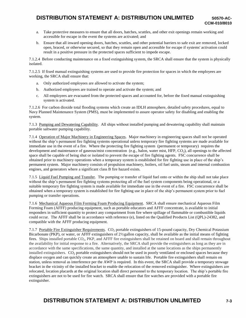
DISTRIBUTION STATEMENT A: DISTRIBUTION UNLIMITED S0570-AC-
CCM-010/8010
DISTRIBUTION STATEMENT A: DISTRIBUTION UNLIMITED 7-3
a. Take protective measures to ensure that all doors, hatches, scuttles, and other exit openings remain working and
accessible for escape in the event the systems are activated; and
b. Ensure that all inward opening doors, hatches, scuttles, and other potential barriers to safe exit are removed, locked
open, braced, or otherwise secured, so that they remain open and accessible for escape if systems' activation could
result in a positive pressure in the protected spaces sufficient to impede escape.
7.1.2.4 Before conducting maintenance on a fixed extinguishing system, the SRCA shall ensure that the system is physically
isolated.
7.1.2.5 If fixed manual extinguishing systems are used to provide fire protection for spaces in which the employees are
working, the SRCA shall ensure that:
a. Only authorized employees are allowed to activate the system;
b. Authorized employees are trained to operate and activate the system; and
c. All employees are evacuated from the protected spaces and accounted for, before the fixed manual extinguishing
system is activated.
7.1.2.6 For carbon dioxide total flooding systems which create an IDLH atmosphere, detailed safety procedures, equal to
Navy Planned Maintenance System (PMS), must be implemented to assure operator safety for disabling and enabling the
system.
7.1.3 Pumping and Dewatering Capability. All ships without installed pumping and dewatering capability shall maintain
portable saltwater pumping capability.
7.1.4 Operation of Major Machinery in Engineering Spaces. Major machinery in engineering spaces shall not be operated
without the ship’s permanent fire fighting systems operational unless temporary fire fighting systems are made available for
immediate use in the event of a fire. Where the protecting fire fighting system (permanent or temporary) requires the
development and maintenance of gaseous/mist concentration (e.g., halon, water mist, HFP, CO2), all openings to the affected
space shall be capable of being shut or isolated to prevent the escape of fire fighting agents. FSC concurrence shall be
obtained prior to machinery operations when a temporary system is established for fire fighting use in place of the ship’s
permanent system. Major machinery consists of propulsion machinery, boilers, oil fuel units, steam and internal combustion
engines, and generators where a significant class B fire hazard exists.
7.1.5 Liquid Fuel Pumping and Transfer. The pumping or transfer of liquid fuel onto or within the ship shall not take place
without the ship’s permanent fire fighting systems protecting all of the fuel system components being operational, or a
suitable temporary fire fighting system is made available for immediate use in the event of a fire. FSC concurrence shall be
obtained when a temporary system is established for fire fighting use in place of the ship’s permanent system prior to fuel
pumping or transfer operations.
7.1.6 Mechanical Aqueous Film Forming Foam Producing Equipment. SRCA shall ensure mechanical Aqueous Film
Forming Foam (AFFF) producing equipment, such as portable educators and AFFF concentrate, is available to initial
responders in sufficient quantity to protect any compartment from fire where spillage of flammable or combustible liquids
could occur. The AFFF shall be in accordance with reference (e), listed on the Qualified Products List (QPL)-24382, and
compatible with the AFFF producing equipment.
7.1.7 Portable Fire Extinguisher Requirements. CO2 portable extinguishers of 15-pound capacity, Dry Chemical Potassium
Bicarbonate (PKP), or water, or AFFF extinguishers of 2½ gallon capacity, shall be available as the initial means of fighting
fires. Ships installed portable CO2, PKP, and AFFF fire extinguishers shall be retained on board and shall remain throughout
the availability for initial response to a fire. Alternatively, the SRCA shall provide the extinguishers as long as they are in
accordance with the same specifications, the same quantity, and installed at the same locations as the ships permanently
installed extinguishers. CO2 portable extinguishers should not be used in poorly ventilated or enclosed spaces because they
displace oxygen and can quickly create an atmosphere unable to sustain life. Portable fire extinguishers shall remain on
station, unless removal as interference per the AWP is required. In this event, the SRCA shall provide a temporary stowage
bracket in the vicinity of the installed bracket to enable the relocation of the removed extinguisher. Where extinguishers are
relocated, location placards at the original location shall direct personnel to the temporary location. The ship’s portable fire
extinguishers are not to be used for fire watch. SRCA shall ensure that fire watches are provided with a portable fire
extinguisher.
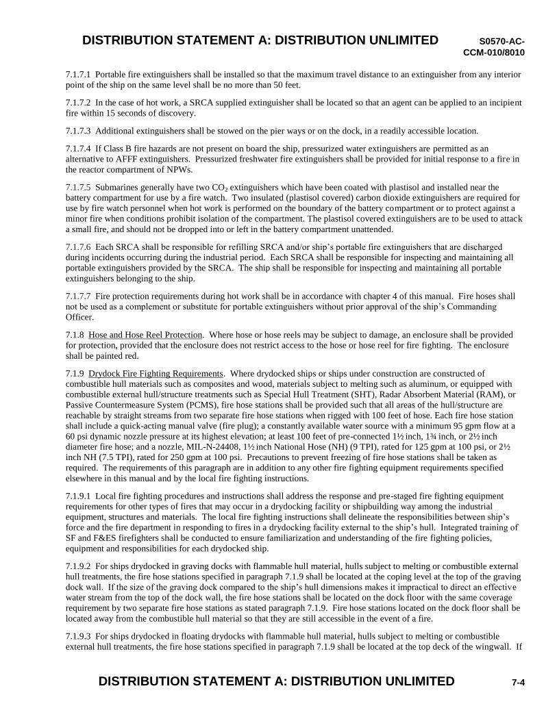
DISTRIBUTION STATEMENT A: DISTRIBUTION UNLIMITED S0570-AC-
CCM-010/8010
DISTRIBUTION STATEMENT A: DISTRIBUTION UNLIMITED 7-4
7.1.7.1 Portable fire extinguishers shall be installed so that the maximum travel distance to an extinguisher from any interior
point of the ship on the same level shall be no more than 50 feet.
7.1.7.2 In the case of hot work, a SRCA supplied extinguisher shall be located so that an agent can be applied to an incipient
fire within 15 seconds of discovery.
7.1.7.3 Additional extinguishers shall be stowed on the pier ways or on the dock, in a readily accessible location.
7.1.7.4 If Class B fire hazards are not present on board the ship, pressurized water extinguishers are permitted as an
alternative to AFFF extinguishers. Pressurized freshwater fire extinguishers shall be provided for initial response to a fire in
the reactor compartment of NPWs.
7.1.7.5 Submarines generally have two CO2 extinguishers which have been coated with plastisol and installed near the
battery compartment for use by a fire watch. Two insulated (plastisol covered) carbon dioxide extinguishers are required for
use by fire watch personnel when hot work is performed on the boundary of the battery compartment or to protect against a
minor fire when conditions prohibit isolation of the compartment. The plastisol covered extinguishers are to be used to attack
a small fire, and should not be dropped into or left in the battery compartment unattended.
7.1.7.6 Each SRCA shall be responsible for refilling SRCA and/or ship’s portable fire extinguishers that are discharged
during incidents occurring during the industrial period. Each SRCA shall be responsible for inspecting and maintaining all
portable extinguishers provided by the SRCA. The ship shall be responsible for inspecting and maintaining all portable
extinguishers belonging to the ship.
7.1.7.7 Fire protection requirements during hot work shall be in accordance with chapter 4 of this manual. Fire hoses shall
not be used as a complement or substitute for portable extinguishers without prior approval of the ship’s Commanding
Officer.
7.1.8 Hose and Hose Reel Protection. Where hose or hose reels may be subject to damage, an enclosure shall be provided
for protection, provided that the enclosure does not restrict access to the hose or hose reel for fire fighting. The enclosure
shall be painted red.
7.1.9 Drydock Fire Fighting Requirements. Where drydocked ships or ships under construction are constructed of
combustible hull materials such as composites and wood, materials subject to melting such as aluminum, or equipped with
combustible external hull/structure treatments such as Special Hull Treatment (SHT), Radar Absorbent Material (RAM), or
Passive Countermeasure System (PCMS), fire hose stations shall be provided such that all areas of the hull/structure are
reachable by straight streams from two separate fire hose stations when rigged with 100 feet of hose. Each fire hose station
shall include a quick-acting manual valve (fire plug); a constantly available water source with a minimum 95 gpm flow at a
60 psi dynamic nozzle pressure at its highest elevation; at least 100 feet of pre-connected 1½ inch, 1¾ inch, or 2½ inch
diameter fire hose; and a nozzle, MIL-N-24408, 1½ inch National Hose (NH) (9 TPI), rated for 125 gpm at 100 psi, or 2½
inch NH (7.5 TPI), rated for 250 gpm at 100 psi. Precautions to prevent freezing of fire hose stations shall be taken as
required. The requirements of this paragraph are in addition to any other fire fighting equipment requirements specified
elsewhere in this manual and by the local fire fighting instructions.
7.1.9.1 Local fire fighting procedures and instructions shall address the response and pre-staged fire fighting equipment
requirements for other types of fires that may occur in a drydocking facility or shipbuilding way among the industrial
equipment, structures and materials. The local fire fighting instructions shall delineate the responsibilities between ship’s
force and the fire department in responding to fires in a drydocking facility external to the ship’s hull. Integrated training of
SF and F&ES firefighters shall be conducted to ensure familiarization and understanding of the fire fighting policies,
equipment and responsibilities for each drydocked ship.
7.1.9.2 For ships drydocked in graving docks with flammable hull material, hulls subject to melting or combustible external
hull treatments, the fire hose stations specified in paragraph 7.1.9 shall be located at the coping level at the top of the graving
dock wall. If the size of the graving dock compared to the ship’s hull dimensions makes it impractical to direct an effective
water stream from the top of the dock wall, the fire hose stations shall be located on the dock floor with the same coverage
requirement by two separate fire hose stations as stated paragraph 7.1.9. Fire hose stations located on the dock floor shall be
located away from the combustible hull material so that they are still accessible in the event of a fire.
7.1.9.3 For ships drydocked in floating drydocks with flammable hull material, hulls subject to melting or combustible
external hull treatments, the fire hose stations specified in paragraph 7.1.9 shall be located at the top deck of the wingwall. If
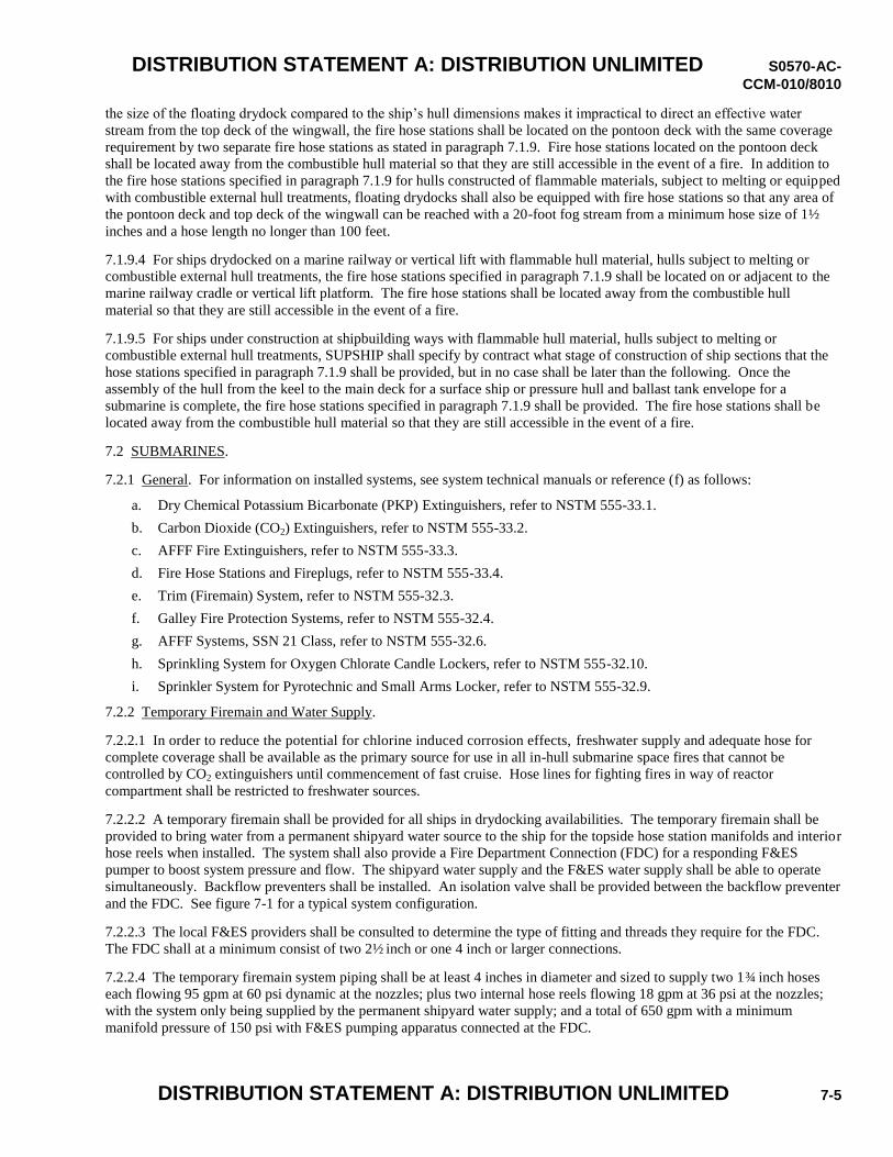
DISTRIBUTION STATEMENT A: DISTRIBUTION UNLIMITED S0570-AC-
CCM-010/8010
DISTRIBUTION STATEMENT A: DISTRIBUTION UNLIMITED 7-5
the size of the floating drydock compared to the ship’s hull dimensions makes it impractical to direct an effective water
stream from the top deck of the wingwall, the fire hose stations shall be located on the pontoon deck with the same coverage
requirement by two separate fire hose stations as stated in paragraph 7.1.9. Fire hose stations located on the pontoon deck
shall be located away from the combustible hull material so that they are still accessible in the event of a fire. In addition to
the fire hose stations specified in paragraph 7.1.9 for hulls constructed of flammable materials, subject to melting or equipped
with combustible external hull treatments, floating drydocks shall also be equipped with fire hose stations so that any area of
the pontoon deck and top deck of the wingwall can be reached with a 20-foot fog stream from a minimum hose size of 1½
inches and a hose length no longer than 100 feet.
7.1.9.4 For ships drydocked on a marine railway or vertical lift with flammable hull material, hulls subject to melting or
combustible external hull treatments, the fire hose stations specified in paragraph 7.1.9 shall be located on or adjacent to the
marine railway cradle or vertical lift platform. The fire hose stations shall be located away from the combustible hull
material so that they are still accessible in the event of a fire.
7.1.9.5 For ships under construction at shipbuilding ways with flammable hull material, hulls subject to melting or
combustible external hull treatments, SUPSHIP shall specify by contract what stage of construction of ship sections that the
hose stations specified in paragraph 7.1.9 shall be provided, but in no case shall be later than the following. Once the
assembly of the hull from the keel to the main deck for a surface ship or pressure hull and ballast tank envelope for a
submarine is complete, the fire hose stations specified in paragraph 7.1.9 shall be provided. The fire hose stations shall be
located away from the combustible hull material so that they are still accessible in the event of a fire.
7.2 SUBMARINES.
7.2.1 General. For information on installed systems, see system technical manuals or reference (f) as follows:
a. Dry Chemical Potassium Bicarbonate (PKP) Extinguishers, refer to NSTM 555-33.1.
b. Carbon Dioxide (CO2) Extinguishers, refer to NSTM 555-33.2.
c. AFFF Fire Extinguishers, refer to NSTM 555-33.3.
d. Fire Hose Stations and Fireplugs, refer to NSTM 555-33.4.
e. Trim (Firemain) System, refer to NSTM 555-32.3.
f. Galley Fire Protection Systems, refer to NSTM 555-32.4.
g. AFFF Systems, SSN 21 Class, refer to NSTM 555-32.6.
h. Sprinkling System for Oxygen Chlorate Candle Lockers, refer to NSTM 555-32.10.
i. Sprinkler System for Pyrotechnic and Small Arms Locker, refer to NSTM 555-32.9.
7.2.2 Temporary Firemain and Water Supply.
7.2.2.1 In order to reduce the potential for chlorine induced corrosion effects, freshwater supply and adequate hose for
complete coverage shall be available as the primary source for use in all in-hull submarine space fires that cannot be
controlled by CO2 extinguishers until commencement of fast cruise. Hose lines for fighting fires in way of reactor
compartment shall be restricted to freshwater sources.
7.2.2.2 A temporary firemain shall be provided for all ships in drydocking availabilities. The temporary firemain shall be
provided to bring water from a permanent shipyard water source to the ship for the topside hose station manifolds and interior
hose reels when installed. The system shall also provide a Fire Department Connection (FDC) for a responding F&ES
pumper to boost system pressure and flow. The shipyard water supply and the F&ES water supply shall be able to operate
simultaneously. Backflow preventers shall be installed. An isolation valve shall be provided between the backflow preventer
and the FDC. See figure 7-1 for a typical system configuration.
7.2.2.3 The local F&ES providers shall be consulted to determine the type of fitting and threads they require for the FDC.
The FDC shall at a minimum consist of two 2½ inch or one 4 inch or larger connections.
7.2.2.4 The temporary firemain system piping shall be at least 4 inches in diameter and sized to supply two 1¾ inch hoses
each flowing 95 gpm at 60 psi dynamic at the nozzles; plus two internal hose reels flowing 18 gpm at 36 psi at the nozzles;
with the system only being supplied by the permanent shipyard water supply; and a total of 650 gpm with a minimum
manifold pressure of 150 psi with F&ES pumping apparatus connected at the FDC.
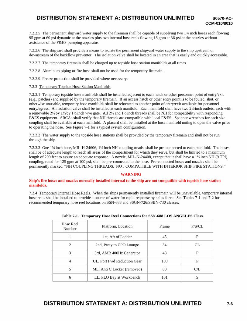
DISTRIBUTION STATEMENT A: DISTRIBUTION UNLIMITED S0570-AC-
CCM-010/8010
DISTRIBUTION STATEMENT A: DISTRIBUTION UNLIMITED 7-6
7.2.2.5 The permanent shipyard water supply to the firemain shall be capable of supplying two 1¾ inch hoses each flowing
95 gpm at 60 psi dynamic at the nozzles plus two internal hose reels flowing 18 gpm at 36 psi at the nozzles without
assistance of the F&ES pumping apparatus.
7.2.2.6 The shipyard shall provide a means to isolate the permanent shipyard water supply to the ship upstream or
downstream of the backflow preventer. The isolation valve shall be located in an area that is easily and quickly accessible.
7.2.2.7 The temporary firemain shall be charged up to topside hose station manifolds at all times.
7.2.2.8 Aluminum piping or fire hose shall not be used for the temporary firemain.
7.2.2.9 Freeze protection shall be provided where necessary.
7.2.3 Temporary Topside Hose Station Manifolds.
7.2.3.1 Temporary topside hose manifolds shall be installed adjacent to each hatch or other personnel point of entry/exit
(e.g., patches) and supplied by the temporary firemain. If an access hatch or other entry point is to be fouled, shut, or
otherwise unusable, temporary hose manifolds shall be relocated to another point of entry/exit available for personnel
entry/egress. An isolation valve shall be installed at each manifold. Each manifold shall have two 2½ inch outlets, each with
a removable 2½ by 1½ by 1½ inch wye gate. All 2½ and 1½ inch threads shall be NH for compatibility with responding
F&ES equipment. SRCAs shall verify that NH threads are compatible with local F&ES. Spanner wrenches for each size
coupling shall be available at each manifold. A placard shall be installed at the hose manifold noting to open the valve prior
to operating the hose. See Figure 7-1 for a typical system configuration.
7.2.3.2 The water supply to the topside hose stations shall be provided by the temporary firemain and shall not be run
through the ship.
7.2.3.3 One 1¾ inch hose, MIL-H-24606, 1½ inch NH coupling treads, shall be pre-connected to each manifold. The hoses
shall be of adequate length to reach all areas of the compartment for which they serve, but shall be limited to a maximum
length of 200 feet to assure an adequate response. A nozzle, MIL-N-24408, except that it shall have a 1½ inch NH (9 TPI)
coupling, rated for 125 gpm at 100 psi, shall be pre-connected to the hose. Pre-connected hoses and nozzles shall be
permanently marked, “NH COUPLING THREADS. NOT COMPATIBLE WITH INTERIOR SHIP FIRE STATIONS.”
WARNING
Ship’s fire hoses and nozzles normally installed internal to the ship are not compatible with topside hose station
manifolds.
7.2.4 Temporary Internal Hose Reels. When the ships permanently installed firemain will be unavailable, temporary internal
hose reels shall be installed to provide a source of water for rapid response by ships force. See Tables 7-1 and 7-2 for
recommended temporary hose reel locations on SSN-688 and SSGN-726/SSBN-730 classes.
Table 7-1. Temporary Hose Reel Connections for SSN-688 LOS ANGELES Class.
Hose Reel
Number Platform, Location Frame P/S/CL
1 1st, Aft of Ladder 45 P
2 2nd, Pway to CPO Lounge 34 CL
3 3rd, AMR 400Hz Generator 48 P
4 UL, Port Fwd Reduction Gear 100 P
5 ML, Anti C Locker (removed) 80 C/L
6 LL, PLO Bay at Workbench 101 S
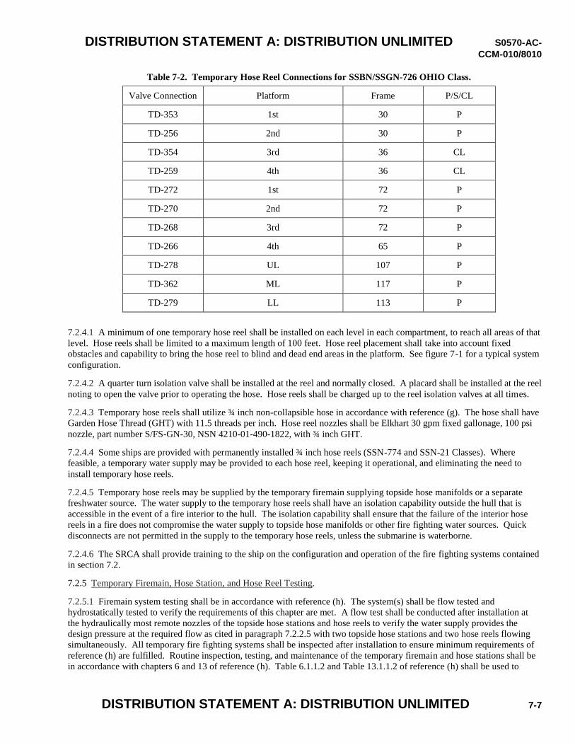
DISTRIBUTION STATEMENT A: DISTRIBUTION UNLIMITED S0570-AC-
CCM-010/8010
DISTRIBUTION STATEMENT A: DISTRIBUTION UNLIMITED 7-7
Table 7-2. Temporary Hose Reel Connections for SSBN/SSGN-726 OHIO Class.
Valve Connection Platform Frame P/S/CL
TD-353 1st 30 P
TD-256 2nd 30 P
TD-354 3rd 36 CL
TD-259 4th 36 CL
TD-272 1st 72 P
TD-270 2nd 72 P
TD-268 3rd 72 P
TD-266 4th 65 P
TD-278 UL 107 P
TD-362 ML 117 P
TD-279 LL 113 P
7.2.4.1 A minimum of one temporary hose reel shall be installed on each level in each compartment, to reach all areas of that
level. Hose reels shall be limited to a maximum length of 100 feet. Hose reel placement shall take into account fixed
obstacles and capability to bring the hose reel to blind and dead end areas in the platform. See figure 7-1 for a typical system
configuration.
7.2.4.2 A quarter turn isolation valve shall be installed at the reel and normally closed. A placard shall be installed at the reel
noting to open the valve prior to operating the hose. Hose reels shall be charged up to the reel isolation valves at all times.
7.2.4.3 Temporary hose reels shall utilize ¾ inch non-collapsible hose in accordance with reference (g). The hose shall have
Garden Hose Thread (GHT) with 11.5 threads per inch. Hose reel nozzles shall be Elkhart 30 gpm fixed gallonage, 100 psi
nozzle, part number S/FS-GN-30, NSN 4210-01-490-1822, with ¾ inch GHT.
7.2.4.4 Some ships are provided with permanently installed ¾ inch hose reels (SSN-774 and SSN-21 Classes). Where
feasible, a temporary water supply may be provided to each hose reel, keeping it operational, and eliminating the need to
install temporary hose reels.
7.2.4.5 Temporary hose reels may be supplied by the temporary firemain supplying topside hose manifolds or a separate
freshwater source. The water supply to the temporary hose reels shall have an isolation capability outside the hull that is
accessible in the event of a fire interior to the hull. The isolation capability shall ensure that the failure of the interior hose
reels in a fire does not compromise the water supply to topside hose manifolds or other fire fighting water sources. Quick
disconnects are not permitted in the supply to the temporary hose reels, unless the submarine is waterborne.
7.2.4.6 The SRCA shall provide training to the ship on the configuration and operation of the fire fighting systems contained
in section 7.2.
7.2.5 Temporary Firemain, Hose Station, and Hose Reel Testing.
7.2.5.1 Firemain system testing shall be in accordance with reference (h). The system(s) shall be flow tested and
hydrostatically tested to verify the requirements of this chapter are met. A flow test shall be conducted after installation at
the hydraulically most remote nozzles of the topside hose stations and hose reels to verify the water supply provides the
design pressure at the required flow as cited in paragraph 7.2.2.5 with two topside hose stations and two hose reels flowing
simultaneously. All temporary fire fighting systems shall be inspected after installation to ensure minimum requirements of
reference (h) are fulfilled. Routine inspection, testing, and maintenance of the temporary firemain and hose stations shall be
in accordance with chapters 6 and 13 of reference (h). Table 6.1.1.2 and Table 13.1.1.2 of reference (h) shall be used to
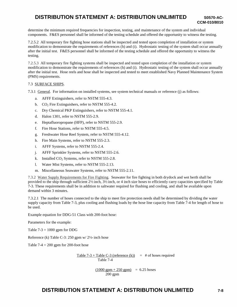
DISTRIBUTION STATEMENT A: DISTRIBUTION UNLIMITED S0570-AC-
CCM-010/8010
DISTRIBUTION STATEMENT A: DISTRIBUTION UNLIMITED 7-8
determine the minimum required frequencies for inspection, testing, and maintenance of the system and individual
components. F&ES personnel shall be informed of the testing schedule and offered the opportunity to witness the testing.
7.2.5.2 All temporary fire fighting hose stations shall be inspected and tested upon completion of installation or system
modification to demonstrate the requirements of references (h) and (i). Hydrostatic testing of the system shall occur annually
after the initial test. F&ES personnel shall be informed of the testing schedule and offered the opportunity to witness the
testing.
7.2.5.3 All temporary fire fighting systems shall be inspected and tested upon completion of the installation or system
modification to demonstrate the requirements of references (h) and (i). Hydrostatic testing of the system shall occur annually
after the initial test. Hose reels and hose shall be inspected and tested to meet established Navy Planned Maintenance System
(PMS) requirements.
7.3 SURFACE SHIPS.
7.3.1 General. For information on installed systems, see system technical manuals or reference (j) as follows:
a. AFFF Extinguishers, refer to NSTM 555-4.3.
b. CO2 Fire Extinguishers, refer to NSTM 555-4.2.
c. Dry Chemical PKP Extinguishers, refer to NSTM 555-4.1.
d. Halon 1301, refer to NSTM 555-2.9.
e. Heptafluoropropane (HFP), refer to NSTM 555-2.9.
f. Fire Hose Stations, refer to NSTM 555-4.5.
g. Freshwater Hose Reel System, refer to NSTM 555-4.12.
h. Fire Main Systems, refer to NSTM 555-2.3.
i. AFFF Systems, refer to NSTM 555-2.4.
j. AFFF Sprinkler Systems, refer to NSTM 555-2.6.
k. Installed CO2 Systems, refer to NSTM 555-2.8.
l. Water Mist Systems, refer to NSTM 555-2.13.
m. Miscellaneous Seawater Systems, refer to NSTM 555-2.11.
7.3.2 Water Supply Requirements for Fire Fighting. Seawater for fire fighting in both drydock and wet berth shall be
provided to the ship through sufficient 2½ inch, 3½ inch, or 4 inch size hoses to efficiently carry capacities specified by Table
7-3. These requirements shall be in addition to saltwater required for flushing and cooling, and shall be available upon
demand within 3 minutes.
7.3.2.1 The number of hoses connected to the ship to meet fire protection needs shall be determined by dividing the water
supply capacity from Table 7-3, plus cooling and flushing loads by the hose line capacity from Table 7-4 for length of hose to
be used.
Example equation for DDG-51 Class with 200-foot hose:
Parameters for the example:
Table 7-3 = 1000 gpm for DDG
Reference (k) Table C-3: 250 gpm w/ 2½- inch hose
Table 7-4 = 200 gpm for 200-foot hose
Table 7-3 + Table C-3 (reference (k)) = # of hoses required
Table 7-4
(1000 gpm + 250 gpm) = 6.25 hoses
200 gpm
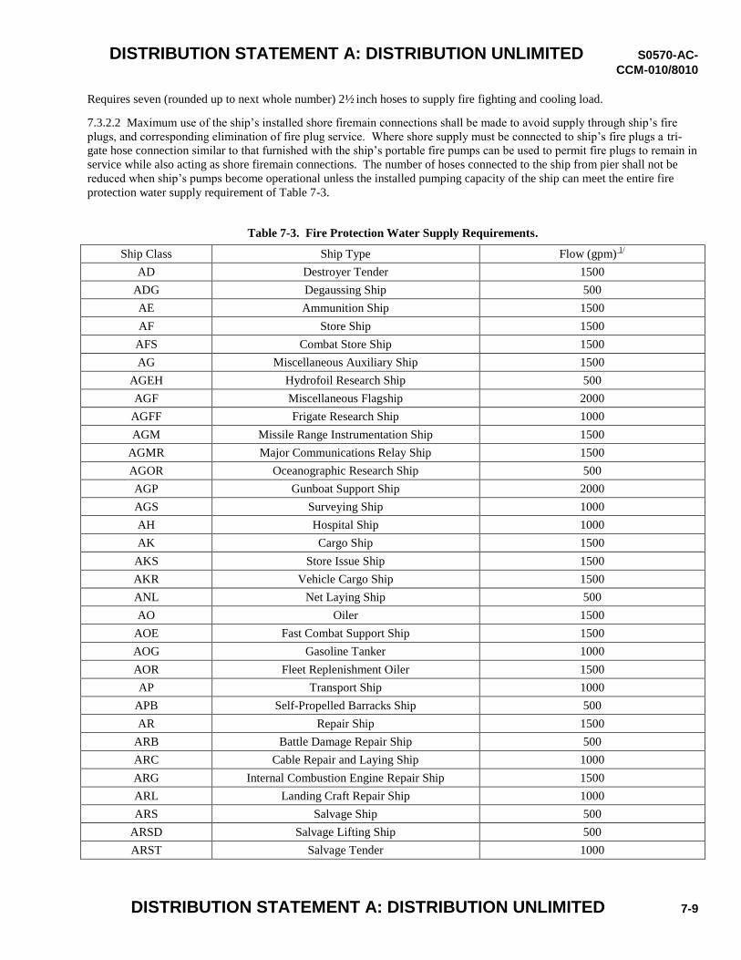
DISTRIBUTION STATEMENT A: DISTRIBUTION UNLIMITED S0570-AC-
CCM-010/8010
DISTRIBUTION STATEMENT A: DISTRIBUTION UNLIMITED 7-9
Requires seven (rounded up to next whole number) 2½ inch hoses to supply fire fighting and cooling load.
7.3.2.2 Maximum use of the ship’s installed shore firemain connections shall be made to avoid supply through ship’s fire
plugs, and corresponding elimination of fire plug service. Where shore supply must be connected to ship’s fire plugs a tri-
gate hose connection similar to that furnished with the ship’s portable fire pumps can be used to permit fire plugs to remain in
service while also acting as shore firemain connections. The number of hoses connected to the ship from pier shall not be
reduced when ship’s pumps become operational unless the installed pumping capacity of the ship can meet the entire fire
protection water supply requirement of Table 7-3.
Table 7-3. Fire Protection Water Supply Requirements.
Ship Class Ship Type Flow (gpm) 1/
AD Destroyer Tender 1500
ADG Degaussing Ship 500
AE Ammunition Ship 1500
AF Store Ship 1500
AFS Combat Store Ship 1500
AG Miscellaneous Auxiliary Ship 1500
AGEH Hydrofoil Research Ship 500
AGF Miscellaneous Flagship 2000
AGFF Frigate Research Ship 1000
AGM Missile Range Instrumentation Ship 1500
AGMR Major Communications Relay Ship 1500
AGOR Oceanographic Research Ship 500
AGP Gunboat Support Ship 2000
AGS Surveying Ship 1000
AH Hospital Ship 1000
AK Cargo Ship 1500
AKS Store Issue Ship 1500
AKR Vehicle Cargo Ship 1500
ANL Net Laying Ship 500
AO Oiler 1500
AOE Fast Combat Support Ship 1500
AOG Gasoline Tanker 1000
AOR Fleet Replenishment Oiler 1500
AP Transport Ship 1000
APB Self-Propelled Barracks Ship 500
AR Repair Ship 1500
ARB Battle Damage Repair Ship 500
ARC Cable Repair and Laying Ship 1000
ARG Internal Combustion Engine Repair Ship 1500
ARL Landing Craft Repair Ship 1000
ARS Salvage Ship 500
ARSD Salvage Lifting Ship 500
ARST Salvage Tender 1000
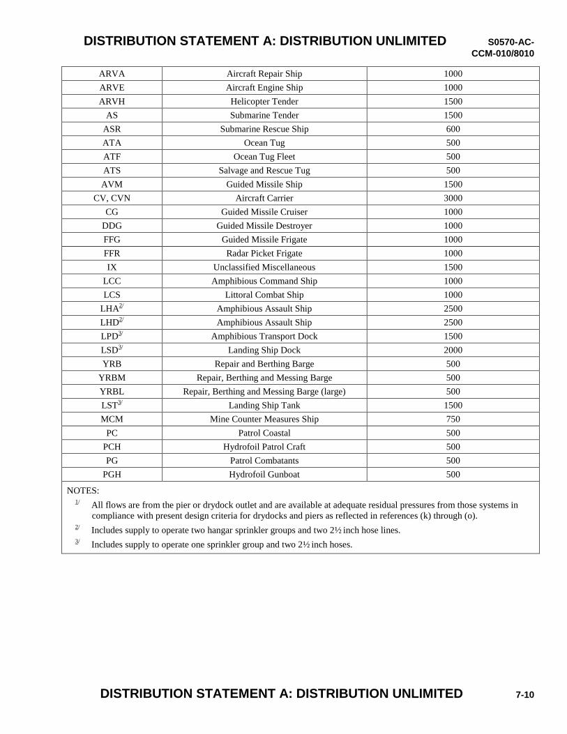
DISTRIBUTION STATEMENT A: DISTRIBUTION UNLIMITED S0570-AC-
CCM-010/8010
DISTRIBUTION STATEMENT A: DISTRIBUTION UNLIMITED 7-10
ARVA Aircraft Repair Ship 1000
ARVE Aircraft Engine Ship 1000
ARVH Helicopter Tender 1500
AS Submarine Tender 1500
ASR Submarine Rescue Ship 600
ATA Ocean Tug 500
ATF Ocean Tug Fleet 500
ATS Salvage and Rescue Tug 500
AVM Guided Missile Ship 1500
CV, CVN Aircraft Carrier 3000
CG Guided Missile Cruiser 1000
DDG Guided Missile Destroyer 1000
FFG Guided Missile Frigate 1000
FFR Radar Picket Frigate 1000
IX Unclassified Miscellaneous 1500
LCC Amphibious Command Ship 1000
LCS Littoral Combat Ship 1000
LHA2/
Amphibious Assault Ship 2500
LHD2/
Amphibious Assault Ship 2500
LPD3/
Amphibious Transport Dock 1500
LSD3/
Landing Ship Dock 2000
YRB Repair and Berthing Barge 500
YRBM Repair, Berthing and Messing Barge 500
YRBL Repair, Berthing and Messing Barge (large) 500
LST3/
Landing Ship Tank 1500
MCM Mine Counter Measures Ship 750
PC Patrol Coastal 500
PCH Hydrofoil Patrol Craft 500
PG Patrol Combatants 500
PGH Hydrofoil Gunboat 500
NOTES: 1/
All flows are from the pier or drydock outlet and are available at adequate residual pressures from those systems in
compliance with present design criteria for drydocks and piers as reflected in references (k) through (o). 2/
Includes supply to operate two hangar sprinkler groups and two 2½ inch hose lines. 3/
Includes supply to operate one sprinkler group and two 2½ inch hoses.
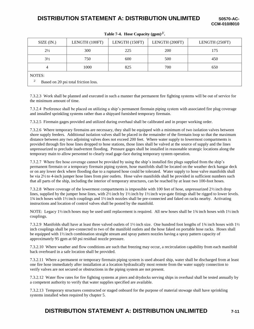
DISTRIBUTION STATEMENT A: DISTRIBUTION UNLIMITED S0570-AC-
CCM-010/8010
DISTRIBUTION STATEMENT A: DISTRIBUTION UNLIMITED 7-11
Table 7-4. Hose Capacity (gpm) 1/
.
SIZE (IN.) LENGTH (100FT) LENGTH (150FT) LENGTH (200FT) LENGTH (250FT)
2½ 300 225 200 175
3½ 750 600 500 450
4 1000 825 700 650
NOTES: 1/
Based on 20 psi total friction loss.
7.3.2.3 Work shall be planned and executed in such a manner that permanent fire fighting systems will be out of service for
the minimum amount of time.
7.3.2.4 Preference shall be placed on utilizing a ship’s permanent firemain piping system with associated fire plug coverage
and installed sprinkling systems rather than a shipyard furnished temporary firemain.
7.3.2.5 Firemain gages provided and utilized during overhaul shall be calibrated and in proper working order.
7.3.2.6 Where temporary firemains are necessary, they shall be equipped with a minimum of two isolation valves between
shore supply feeders. Additional isolation valves shall be placed in the remainder of the firemain loop so that the maximum
distance between any two adjoining valves does not exceed 200 feet. Where water supply to lowermost compartments is
provided through fire hose lines dropped to hose stations, those lines shall be valved at the source of supply and the lines
unpressurized to preclude inadvertent flooding. Pressure gages shall be installed in reasonable strategic locations along the
temporary main to allow personnel to clearly read gage-face during temporary system operation.
7.3.2.7 Where fire hose coverage cannot be provided by using the ship’s installed fire plugs supplied from the ship’s
permanent firemain or a temporary firemain piping system, hose manifolds shall be located on the weather deck hangar deck
or on any lower deck where flooding due to a ruptured hose could be tolerated. Water supply to hose valve manifolds shall
be via 2½ to 4-inch jumper hose lines from pier outlets. Hose valve manifolds shall be provided in sufficient numbers such
that all parts of the ship, including the interior of temporary structures, can be reached by at least two 100-foot hoses.
7.3.2.8 Where coverage of the lowermost compartments is impossible with 100 feet of hose, unpressurized 2½ inch drop
lines, supplied by the jumper hose lines, with 2½ inch by 1½ inch by 1½ inch wye-gate fittings shall be rigged to lower levels.
1¾ inch hoses with 1½ inch couplings and 1½ inch nozzles shall be pre-connected and faked on racks nearby. Activating
instructions and location of control valves shall be posted by the manifold.
NOTE: Legacy 1½ inch hoses may be used until replacement is required. All new hoses shall be 1¾ inch hoses with 1½ inch
couplings.
7.3.2.9 Manifolds shall have at least three valved outlets of 1½ inch size. One hundred foot lengths of 1¾ inch hoses with 1½
inch couplings shall be pre-connected to two of the manifold outlets and the hose faked on portable hose racks. Hoses shall
be equipped with 1½ inch combination straight stream and spray pattern nozzles having a spray pattern capacity of
approximately 95 gpm at 60 psi residual nozzle pressure.
7.3.2.10 Where weather and flow conditions are such that freezing may occur, a recirculation capability from each manifold
back overboard in a safe location shall be provided.
7.3.2.11 Where a permanent or temporary firemain piping system is used aboard ship, water shall be discharged from at least
one fire hose immediately after installation at a location hydraulically most remote from the water supply connection to
verify valves are not secured or obstructions in the piping system are not present.
7.3.2.12 Water flow rates for fire fighting systems at piers and drydocks serving ships in overhaul shall be tested annually by
a competent authority to verify that water supplies specified are available.
7.3.2.13 Temporary structures constructed or staged onboard for the purpose of material stowage shall have sprinkling
systems installed when required by chapter 5.
DISTRIBUTION STATEMENT A: DISTRIBUTION UNLIMITED S0570-AC-
CCM-010/8010
DISTRIBUTION STATEMENT A: DISTRIBUTION UNLIMITED 7-12
a. Sprinklers shall be listed in accordance with reference (p), and shall be open pendent, upright or sidewall type,
whichever is most suitable for the shape and configuration of the protected area. Pendent and upright sprinklers
shall have 180 degree full cone spray patterns. The sprinkling density shall be 0.2 gpm/sqft and the sprinklers shall
be arranged to cover the entire level of the temporary structure and all contents. The manufacturer’s instructions for
spacing of sprinklers, distance from the overhead of the protected area, and distance from stowed material or
obstructions shall be followed. Placards shall be placed on the interior of the protected area noting the height that
material cannot be stacked above.
b. The system shall be a dry deluge type, manually operated by a quarter-turn sprinkler valve located outside and near
the access to the structure. The system shall be continuously charged up to the sprinkler valve, from the ship’s
permanent or temporary firemain, using temporary piping or a non-collapsible hose suitable for the pressure and
flow. Piping downstream of the sprinkler valve shall be metal, except that aluminum is not permitted. A placard
shall be located at the sprinkler valve identifying the protected area and providing instructions on operating the
sprinkler valve. The water supply shall be provided with freeze protection when necessary.
c. In some cases, extended coverage sidewall sprinklers may be the most efficient way to provide coverage by
installing a single line of sprinklers along one edge of the protected area, near the overhead, directed to spray into
the protected area. Most sidewall sprinklers are limited to a range of 16 to 24 feet of spray in one direction and
require that storage and floor-mounted obstructions be located at least 18 to 36 inches below the sprinkler deflector
throughout the protected space. In other cases, pendent style sprinklers may be more suitable. Pendent sprinklers
generally allow greater stacking heights of material.
d. Automatic sprinklers, with the heat responsive and activating elements removed, may be substituted for open
(deluge) sprinklers.
7.3.2.14 Temporary structures constructed or staged onboard not for the purpose of material stowage, shall have sprinkling
systems installed when required by chapter 5. Sprinklers shall be listed in accordance with reference (p). The sprinkling
density shall be 0.1 gpm/sqft and the sprinklers shall be arranged to cover the entire level of the temporary structure and all
contents. The system shall be a wet automatic type. The system shall be continuously charged up to the sprinkler, from the
ship’s permanent or temporary firemain. A placard shall be located at the sprinkler valve identifying the protected area and
providing instructions on operating the sprinkler valve. The water supply shall be provided with freeze protection when
necessary. Operation of the sprinkler system shall sound an audible alarm outside the structure. A smoke detection system
shall be installed inside the structure in accordance with reference (q). The system hardware shall be in accordance with
references (r) and (s). Audible alarms shall be provided both inside and outside the structure. Portable AFFF and CO2
extinguishers shall be provided interior to the structure near the access.
7.3.2.15 Per reference (t), fresh water supply and hose coverage shall be available during shipyard maintenance in case a
reactor compartment fire cannot be controlled by CO2 extinguishers. Hose lines for fighting fires in way of reactor
compartment shall be restricted to freshwater sources.
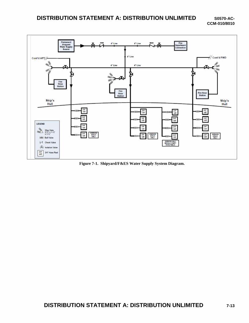
DISTRIBUTION STATEMENT A: DISTRIBUTION UNLIMITED S0570-AC-
CCM-010/8010
DISTRIBUTION STATEMENT A: DISTRIBUTION UNLIMITED 7-13
Figure 7-1. Shipyard/F&ES Water Supply System Diagram.

DISTRIBUTION STATEMENT A: DISTRIBUTION UNLIMITED S0570-AC-
CCM-010/8010
DISTRIBUTION STATEMENT A: DISTRIBUTION UNLIMITED 7-14
THIS PAGE INTENTIONALLY LEFT BLANK.
DISTRIBUTION STATEMENT A: DISTRIBUTION UNLIMITED S0570-AC-
CCM-010/8010
DISTRIBUTION STATEMENT A: DISTRIBUTION UNLIMITED 8-1
Chapter 8 ALARMS AND COMMUNICATIONS
References
(a) Occupational Safety and Health Standards for Shipyard Employment, 29 CFR Part 1915 Subpart P, Fire Protection in
Shipyard Employment
(b) S9AA0-AB-GOS-010, General Overhaul Specifications For Overhaul of Surface Ships (GSO)
(c) S0902-018-2010, General Overhaul Specifications For Deep Diving SSBN/SSN Submarines (DDGOS)
(d) S9086-CN-STM-020, Navy Ships’ Technical Manual (NSTM) Chapter 079, Volume 2, Practical Damage Control
Introduction
In accordance with reference (a), each SRCA is required to maintain functional alarms and communications for use in
shipboard emergencies. The requirements of this chapter were developed from existing requirements in references (b) and
(c) with inherent flexibilities incorporated, and apply to all SRCAs (except new construction shipyards) and cover all Navy
ships – submarines, surface ships, and aircraft carriers.
Due to the industrial work being performed during a maintenance availability, there may be periods of time during which the
ship’s permanent fire reporting and announcing systems are disabled. The inherent risk for personal safety increases during
this time and it is imperative for a temporary means of reporting and announcing a casualty to be provided for shipboard
casualties. The capability for SF, SRCA, and F&ES to communicate on portable radios has been incorporated into section
8.7. These radios are needed to promote integration and coordination between the three entities to promote an effective
response to a major shipboard casualty.
This chapter provides information for Damage Control Central (DCC) (section 8.3 for submarines and 8.4 for surface ships)
guidelines. This includes the necessary information to be staged at the cognizant DCC for use in casualty response. These
required items are vital to ensure a quick, integrated, and effective response between the ship, SRCA, and F&ES responders
during a major shipboard casualty. The FSC has been empowered with the authority to mitigate the risks associated with the
placement of the respective DCC and the required information to be staged at each DCC.
Flexibilities have been incorporated into these requirements to allow each SRCA to adapt their implementation of the
requirements to a given situation. For instance, the allowance is provided in paragraph 8.1.5 for two ships to share a means
of reporting if they are drydocked side by side and this shared means is accessible between the two ships.
8.1 SHIPBOARD FIRE REPORTING SYSTEM. To the extent practicable, the ship’s permanent shipboard casualty
reporting system shall be maintained operational throughout the period of the availability. The SRCA shall provide a
temporary shipboard casualty reporting system to take the place of non-operational permanent components subject to the
following.
8.1.1 Fire Reporting Devices. Fire reporting devices placed shipboard shall be a fire alarm pull box, a direct line telephone,
or a device combining both a pull box and direct line telephone. An adequate number of fire reporting devices, properly
marked and designated with indicator lights, shall be installed to expedite the rapid reporting of fires Fire reporting devices
must be located in each compartment (submarine)/fire zone(surface ship) and not more than 50 feet from any point in the
compartment/fire zone. For submarines only, a topside/outside reporting device shall be installed along the path of travel
within 10 feet of each hatch.
8.1.2 Annunciator Panel. The temporary reporting system shall include an annunciator panel installed at the CASCON
Station and/or DCC/Quarterdeck (as designated by ship’s representative) capable of distinctively indicating which fire
reporting device has been activated. If a device circuit does not produce a coded audible alarm, the CASCON Station and/or
DCC/Quarterdeck shall have the capability to sound a follow-up alarm or announcement to designate the reported fire area.
Working personnel shall be kept informed as to box locations and actions to be taken when the alarm is sounded.
DISTRIBUTION STATEMENT A: DISTRIBUTION UNLIMITED S0570-AC-
CCM-010/8010
DISTRIBUTION STATEMENT A: DISTRIBUTION UNLIMITED 8-2
8.1.3 Reporting to Emergency Dispatch Center. The means of reporting fire incidents to the emergency dispatch center,
installation fire department, and/or contractor fire department shall consist of the following:
8.1.3.1 Fire alarm system equipment that, upon activation of a fire alarm pull box, sends a signal via a direct electrically
supervised circuit to a central station service, a remote station service, a cognizant fire department, a shipyard fire
department, or a continuously manned location where trained operators can take immediate action to transmit an alarm to the
fire department. The furnished fire alarm systems shall be reliable and provide facilities at the centrally manned location for
making daily tests of the system.
8.1.3.2 A telephone that directly connects to the emergency dispatch center (e.g., “hotline” or “redphone”) or a touchtone
telephone equipped with a sign that contains the emergency number/extension for the emergency dispatch center to provide
verbal verification of alarms and augmenting information.
8.1.4 Defective or Inoperative Alarms. Defective or inoperative alarms shall be repaired or replaced immediately. No hot
work shall be performed in affected areas without operational fire reporting systems, unless a mitigation plan is approved by
the FSC. The FSC will control mitigation of resuming all other work items.
8.1.5 Fire Reporting in DryDock. When a ship is in drydock, a means of reporting a fire shall be placed at least every 100
feet on the drydock floor under the length of the ship so that personnel working under the ship can quickly report. If two
ships are drydocked side by side, they may share the means of reporting if accessible between the two ships.
8.2 CASUALTY GENERAL ANNOUNCING SYSTEM. To the extent practicable, the ship’s permanent shipboard general
announcing system shall be maintained operational throughout the period of the availability. If the ship’s permanent
shipboard general announcing system cannot be maintained fully operational, the SRCA shall provide temporary general
announcing components or an entire system to ensure an equivalent audibility within ship as that of the ship's permanent
shipboard system is maintained.
8.2.1 Temporary System. A temporary system shall be installed which can be heard in spaces that are not normally manned
and a general announcing system cannot be heard such as occupied tanks and voids, including tanks entered through hull cut
access when in drydock. Watch-standers may serve as an alternative communication system to these areas, provided that all
personnel can be alerted. In addition, a means shall be provided to transmit general announcements to topside areas of the
ship as well as drydock basin areas.
8.2.2 Testing of Systems. The ship’s permanent and temporary installed announcing system shall be tested at least once
daily. When audible alarms cannot provide effective notification, an alternative method shall be employed as approved by
the FSC with notification to the local safety office and emergency dispatch center.
8.2.3 Brief Outages. Brief outages, limited to four hours or less, of ship’s operational general announcing systems for
emergent mandatory maintenance, or to allow transfer to/from the temporary system, may be allowed based on approval by
the FSC and concurrence from the ship’s CO. A mitigation plan shall be in place to ensure all shipboard personnel can be
alerted in the case of an emergency.
8.2.4 Hot Work. No hot work shall be performed without an operational general announcing system.
8.3 DAMAGE CONTROL CENTRAL/CASCON STATION, SUBMARINES.
8.3.1 Location of CASCON Station. A CASCON Station shall be located aboard or near and in sight of the ship, or at the
SF Topside Watch Station. The CASCON Station location shall be approved by the FSC and may serve more than one ship
provided individual ship’s information is clearly identified.
8.3.2 Fire Detection System Alarm Panel. If an automatic fire detection system required per chapter 6, is installed then the
associated detection system alarm panel shall be co-located at the CASCON Station.
8.3.3 Required Items at CASCON Station. The following items shall be located at DCC and the CASCON Station to assist
with fire notification and response:
a. A fire bill and elsewhere on the ship as needed, which describes how to turn in an alarm and actions to be taken by
SRCA personnel in case of fire.
DISTRIBUTION STATEMENT A: DISTRIBUTION UNLIMITED S0570-AC-
CCM-010/8010
DISTRIBUTION STATEMENT A: DISTRIBUTION UNLIMITED 8-3
b. Telephones for communicating to the shore and internally within the ship. Emergency dispatch center and F&ES
Department response numbers shall be posted with telephone.
c. Procedures for notifying employees and fire response organizations of a fire emergency and/or unsafe condition.
d. Fire zone boundary status.
e. Simplified ship information (supplied by SRCA) showing: compartments, access status, and temporary service
system configuration (including isolations). These diagrams shall include the status of hull openings and temporary
(internal and external) access cuts and their plan for closure to prevent a “chimney effect” in the event of a fire, and
fire/flooding protections status and pumping facilities.
(1) Compartments/spaces and access status.
(2) Emergency systems installed by the SRCA for communications, lighting, and alarms, including location of
operating switches.
(3) Temporary service system configuration of major service lines, including isolations.
(4) The status of hull openings and temporary (internal and external) access cuts and their plan for closure to
prevent a “chimney effect” in the event of a fire, fire/flooding protection status, and pumping facilities.
f. Locator diagrams for the ship temporary flooding control equipment.
g. Diagrams documenting any departure from the ship’s normal de-watering systems line-up, which includes
temporary de-watering hose routes.
h. Updated list of significant shipboard fire hazards.
i. A current file of SRCA safety directives and casualty control procedures.
j. Temporary fire reporting system annunciator panel and alarm transmission equipment described in paragraphs 8.1.2
and 8.1.3.1.
8.4 DAMAGE CONTROL CENTRAL/QUARTERDECK, SURFACE SHIPS.
8.4.1 Damage Control Policies and Procedures. Ship’s damage control policies and procedures shall be per the requirements
of reference (d). The central casualty control station (normally the ship’s DCC) shall be used for both fire protection and
response purposes. The ship’s DCC shall also function, at least initially, as a command post for directing fire fighting
operations of both military and civilian personnel, assuming it is not rendered untenable due to the fire.
8.4.2 Alternate DCC. For all ships not possessing an operational DCC, a suitable equivalent shall be provided.
8.4.3 DCC Located Off Ship. If DCC is not relocated to another space within the ship, then it may be established off the
ship within close proximity to the ship.
8.4.4 Receiving and Escorting F&ES Officers. The Ship’s Quarterdeck will serve as the central location for receiving and
escorting F&ES officers to DCC or other shipboard command post location.
8.4.5 Required Items at DCC/Quarterdeck. The following items shall be located at DCC and the Quarterdeck to assist with
fire notification and response:
a. Telephones for communicating to the shore and internally within the ship. Emergency dispatch center and F&ES
Department response numbers shall be posted with telephone.
b. A fire bill, which describes how to turn in an alarm and actions to be taken by SRCA personnel in case of fire.
Additional fire bills shall be located elsewhere on the ship as needed.
c. Procedures for notifying employees and fire response organizations of a fire emergency and/or unsafe condition.
d. The ship’s damage control books and plates (DCC only).
e. Fire zone boundary status.
f. Simplified ship information (supplied by SRCA) showing:
(1) Compartments/spaces and access status.
(2) Emergency systems installed by the SRCA for communications, lighting, and alarms, including location of
operating switches.
DISTRIBUTION STATEMENT A: DISTRIBUTION UNLIMITED S0570-AC-
CCM-010/8010
DISTRIBUTION STATEMENT A: DISTRIBUTION UNLIMITED 8-4
(3) Temporary service system configuration of major service backbones/trunks, including isolations.
(4) The status of hull openings and temporary (internal and external) access cuts and their plan for closure to
prevent a “chimney effect” in the event of a fire, fire/flooding protection status, and pumping facilities.
g. Locator diagrams for the ship temporary flooding control equipment.
h. Diagrams documenting any departure from the ship’s normal de-watering systems line-up, which includes
temporary de-watering hose routes.
i. Updated list of significant shipboard fire hazards.
j. A current file of SRCA safety directives and casualty control procedures.
k. Temporary fire reporting system annunciator panel and alarm transmission equipment described in paragraphs 8.1.2
and 8.1.3.1.
8.5 STOP HOT WORK ALARM SYSTEM.
8.5.1 Requirements. An alarm system shall be provided to instruct personnel to stop all hot work. The fire alarm circuit
may be utilized for this purpose. However, the hot work alarm shall produce a clear signal distinct from the fire alarm signal.
The hot work alarm shall be actuated from the central CASCON Station and/or DCC/Quarterdeck.
8.5.2 Installed Alarm and Announcing System. The ship’s installed alarm and announcing systems, if operational, may be
used for stop hot work alarm purposes. When so used, it may not be possible to achieve separate fire, stop hot work, and
evacuate ship alarms. In these situations, the ship’s announcing system shall be used to announce the nature of the
emergency in conjunction with the alarm actuation.
8.6 EVACUATE SHIP ALARM SYSTEM. Exceptions to the following are provided in paragraph 8.2.
8.6.1 Requirements. An audible and visible system shall be provided to warn personnel to evacuate the ship. The audible
phase shall consist of a klaxon horn, siren, or other device and shall be clearly distinct from the fire and stop hot work alarms.
Sounding of the evacuation alarm shall be accompanied by the flashing of lights on all alarm box stations. Both the audible
and visible signal shall be actuated from the central CASCON Station and/or DCC/Quarterdeck.
8.6.2 Installed Alarm and Announcing System. The ship’s installed alarm and announcing systems, if operational, may be
used for evacuate ship alarm purposes. When so used, it may not be possible to achieve separate fire, stop hot work, and
evacuate ship alarms. In these situations, the ships announcing system shall be used to announce the nature of the emergency
in conjunction with the alarm actuation.
8.7 PORTABLE RADIOS. NSA shall ensure SF have radios with appropriately programmed channels/frequencies that
allow direct communication with the region or installation fire department to promote effective, interoperable
communications with personnel in hull. Radios and associated frequencies shall be operationally tested daily and exercised
during regularly scheduled fire drills. For every vessel undergoing maintenance in availability, there shall be a minimum of
five (5) handheld radios fully compatible with the Region and/or Installation’s Fire Department communications, maintained,
and prepositioned at the CASCON Station and/or DCC/Quarterdeck for SF to use during a casualty to assure
communications with the emergency dispatch center or fire department.
DISTRIBUTION STATEMENT A: DISTRIBUTION UNLIMITED S0570-AC-
CCM-010/8010
DISTRIBUTION STATEMENT A: DISTRIBUTION UNLIMITED 9-1
Chapter 9 LIGHTING
Introduction
This chapter provides the requirements for temporary lighting systems to ensure normal and emergency lighting in the event
the ship’s permanent lighting systems are not operational during an industrial availability. This chapter applies to all SRCAs
and covers all Navy ships – submarines, surface ships, and aircraft carriers.
There are also requirements to prevent temporary lighting systems from igniting or contributing to a fire. It is important to
consider the scope of the work being performed, condition of the space, and duration for which the ship’s permanent system
will not be operational when implementing these requirements. The FSC has the authority to assess and mitigate these risks
appropriately.
9.1 PERMANENT LIGHTING REQUIREMENTS. To the extent practicable, the ship’s permanent and emergency lighting
systems shall be maintained throughout the period of the availability. When the ship’s lighting systems are not operational,
the SRCA shall provide two sources of lighting to all spaces normally having two sources. The lighting may be the ship’s
permanent and emergency lighting systems or a combination of temporary and ship’s permanent lighting, provided that
separate power sources are utilized for each system. The removal of lighting from a space or compartment that could impede
damage control efforts, personnel egress, and/or casualty responder access shall require approval by the FSC.
9.2 TEMPORARY LIGHTING REQUIREMENTS. When the ship’s lighting systems are not operational due to
maintenance and repair and/or when additional illumination is required for enhanced working conditions, personnel egress,
and/or casualty responder access, the SRCA shall install temporary lighting throughout the ship to provide illumination.
9.2.1 Lighting Guards. Temporary lighting shall be equipped with guards to prevent accidental contact with the bulb. When
the construction of the reflector is such that the bulb is deeply recessed, guards may not be required. Missing bulbs shall be
immediately replaced to minimize potential inadvertent contact with light socket.
9.2.2 Electric Cords. Temporary lights shall be equipped with heavy duty electric cords with connections and insulation
maintained in safe condition. Temporary lights shall not be suspended by their electric cords unless cords and lights are
designed for this means of suspension. Splices which have insulation equal to that of the cable are permitted.
9.2.3 Exposed Non-current-carrying Metal Parts. Exposed non-current-carrying metal parts of temporary lights shall be
grounded either through a third wire in the cable containing the circuit conductors or through a separate wire which is
grounded at the source of the current.
9.2.4 Portable Emergency Lighting Equipment. When temporary lighting from sources outside the ship is the only means of
illumination, portable emergency lighting equipment shall be available to provide illumination for safe movement of crew
members and workers.
9.2.5 Dark Spaces. Workers shall not be permitted to enter dark spaces without a suitable portable light. The use of matches
and open flame lights is prohibited. Temporary lighting stringers or streamers shall be so arranged as to avoid overloading of
branch circuits. Each branch circuit shall be equipped with over current protection of capacity not exceeding the rated
current carrying capacity of the cord used.
9.2.6 Restricted Usage. Temporary lighting fixtures shall not be used to power portable electric tools.

DISTRIBUTION STATEMENT A: DISTRIBUTION UNLIMITED S0570-AC-
CCM-010/8010
DISTRIBUTION STATEMENT A: DISTRIBUTION UNLIMITED 9-2
THIS PAGE INTENTIONALLY LEFT BLANK.
DISTRIBUTION STATEMENT A: DISTRIBUTION UNLIMITED S0570-AC-
CCM-010/8010
DISTRIBUTION STATEMENT A: DISTRIBUTION UNLIMITED 10-1
Chapter 10 SHIPBOARD ACCESS/EGRESS AND ROUTING OF TEMPORARY SERVICES
References
(a) Occupational Safety and Health Standards for Shipyard Employment, 29 CFR Part 1915 Subpart P, Fire Protection in
Shipyard Employment
(b) S9AA0-AB-GOS-010, General Overhaul Specifications For Overhaul of Surface Ships (GSO)
(c) S0902-018-2010, General Overhaul Specifications For Deep Diving SSBN/SSN Submarines (DDGOS)
(d) NAVFAC Unified Facilities Criteria (UFC) 4-152-01, Design: Piers and Wharves
(e) Occupational Safety and Health Standards, 46 CFR Part 164 Subpart 164.009, Non-Combustible Materials for Merchant
Vessels
(f) National Fire Protection Association (NFPA) Codes and Standards 701, Standard Methods of Fire Tests for Flame
Propagation of Textiles and Films
Introduction
This chapter provides the necessary safety requirements for personnel access and egress during an industrial availability to
comply with reference (a), including temporary service routing requirements. This chapter applies to all SRCAs and covers
all Navy ships – submarines, surface ships, and aircraft carriers.
The personnel safety requirements were developed from existing requirements in references (b) and (c) for personnel access
and egress. It is essential to ensure that SF and SRCA workers are able to evacuate, if necessary, during a major shipboard
casualty, while maintaining accessibility for casualty responders to combat the casualty in a quick and effective manner.
Section 10.1 includes opportunities for risk mitigation and FSC involvement to secure one of the designated pathways for
personnel access/egress based on the scope and duration of work being performed.
Additional temporary service routing requirements contained in section 10.4 were developed to minimize, to the extent
practicable, the effect temporary services would have on the casualty responders’ ability to combat the fire.
10.1 SHIPBOARD ACCESS AND EGRESS NUMBER AND LOCATION. Per reference (a), each SRCA shall maintain a
primary and secondary means of access/egress for each vessel, where practicable.
10.1.1 Egress Requirements (Submarines). On submarines, at least two separate means of egress from the ship interior to
topside (not including the Bridge Access Hatch) shall be established. At least one means of egress serving the forward
compartment, and at least one means of egress serving the aft compartment on the ship, shall be maintained. The forward
most and aft most hatches shall be utilized to meet the minimum requirement unless a mitigation plan is approved by the
FSC. For compartments which do not have direct access from the ship interior to topside, at least one access shall be
maintained between adjoining compartments for personnel egress and/or casualty responder access.
a. When one of these hatches needs to be secured for 4 hours or less for the removal and/or installation of equipment,
the SRCA shall receive the review and concurrence of the FSC and provide a notification to the emergency dispatch
center. In this condition, all hot work shall be approved by the FSC and means of access/egress shall be maintained
through the other hatch.
b. If work items require that one of these hatches has to be blocked in excess of 4 hours, a mitigation plan shall be
approved by the FSC and include the requirements of paragraph 10.1.1.1, as a minimum. This mitigation plan may
also include an additional personnel access hull cut as an alternative means of personnel egress and/or casualty
responder access.
10.1.2 Shipboard Access (Submarines). On submarines, at least two brows, gangways or ramps from ship-to-shore, ship-to-
ways, ship to drydock side, or ship to drydock floor shall be provided in sufficient number to permit the rapid egress, under
emergency conditions, of all persons aboard and support fire response. To eliminate a common path of egress, at least two
DISTRIBUTION STATEMENT A: DISTRIBUTION UNLIMITED S0570-AC-
CCM-010/8010
DISTRIBUTION STATEMENT A: DISTRIBUTION UNLIMITED 10-2
brows shall be separated by one-fourth the length of the vessel, at a minimum. Brow requirements for SSBNs moored in a
Waterfront Restricted Area (WRA) will be provided by DIRSSP.
10.1.3 Access to Machinery Space (Surface Ships). On surface ships with three or less accesses to each machinery space, at
least one access shall remain unobstructed for use as an escape route. On surface ships with four or more accesses to the
machinery spaces, at least two accesses shall remain unobstructed for use as an escape route.
10.1.4 Shipboard Access (Surface Ships). On surface ships, one gangway shall be located at the ship’s quarterdeck. For
ships less than 700 feet in length, one additional gangway shall be provided. For ships 700 feet or over in length, two
additional gangways shall be provided. Each gangway shall be located in a separate fire zone unless an alternate arrangement
is approved by the FSC.
10.1.5 Securing of Brow/Gangway. For all ships, when one of the brow/gangways designated for personnel access/egress
needs to be secured for 4 hours or less for the removal and/or installation of equipment, the SRCA shall receive the review
and concurrence of the FSC and provide a notification to the emergency dispatch center. In this condition, the FSC shall
ensure a means of access/egress is maintained via the other required brow(s)/gangway(s).
10.2 MAINTAINING ACCESS AND EGRESS CONDITION.
10.2.1 Brow/Gangway Requirements. Consistent with reference (d), brow/gangways, landing platforms, and steps to/from
each gangway shall be a minimum of 3 feet in width of unobstructed walkway and be designed and constructed to support a
minimum load of 75 pounds per square foot. The entire length of brow/gangways and adjacent areas shall be illuminated
with outdoor use lights. Step up and step off areas shall be free of trip/slip hazards and maintain 7 to 12 inch rise over run.
Note – 7 inch rise may be increased up to 12 inches if uniform throughout entire step up/step off areas. Pallets shall not be
used unless reinforced with a solid non-skid cover and designed to meet the minimum loading requirements herein.
10.2.2 Safety Nets. Safety nets shall be installed under brow/gangways that are not fitted with side rails having a vertical
height of 42 inches nominal and metallic meshing or similar material with small openings (approximately ½ inch) between
the top of the rail and the brow/gangway platform deck. Safety nets, when used, shall extend 6 feet beyond each side of
gangways and platforms.
10.2.3 Condition of Brow/Gangways. Brow/gangways shall be maintained free of debris, ice, snow, and foreign matter.
Each access brow/gangway shall have a clearly readable status board showing the status of all permanent and temporary
access/egress openings, and shall be updated as conditions change. Status boards shall also be used to indicate space layouts
and terminology for the ship, available passageways, and areas where access may be limited due to routing of temporary
services, work in progress and/or secured access and egress routes.
10.2.4 Marking Routes of Escape. Routes of escape leading to exits from inside the ship shall be clearly marked.
10.2.5 Use of Announcing System for Access and Egress Routes. The permanent (or temporary) announcing system shall be
used to inform workers and crew of all secured access and egress routes, and the information shall also be posted on status
boards.
10.3 EMERGENCY AIR BREATHING SYSTEM (SUBMARINES).
10.3.1 Required Emergency Air Breathing System. The installed Emergency Air Breathing (EAB) system on submarines
shall be maintained in operation, or a temporary system shall be installed to maintain an equivalent to the submarines EAB
system while the submarine is habitable. The temporary breathing air systems shall be installed to provide an independent
system for each fire zone. Exceptions to this requirement shall be approved by the FSC.
10.3.2 Service to Maneuvering. When considering a major fire onboard and if portions of the installed EAB system are not
available for use, at a minimum, a temporary breathing air system shall be installed to provide service to maneuvering when
the submarine is no longer habitable. The ship and the maintenance activity shall determine when the submarine is no longer
habitable by mutual agreement. Additionally, to support casualties other than a major fire (e.g., toxic gas), a temporary EAB
system shall be installed to support EABs in key locations throughout the ship as approved by the FSC.
DISTRIBUTION STATEMENT A: DISTRIBUTION UNLIMITED S0570-AC-
CCM-010/8010
DISTRIBUTION STATEMENT A: DISTRIBUTION UNLIMITED 10-3
10.3.3 Breathing Air Supply for Egress. The installed EAB system or a temporary breathing air system shall include a
means to provide a breathing air supply that supports egress from maneuvering to an area external to the submarine that is
safe to breathe. SCBAs and Emergency Escape Breathing Devices (EEBD) are acceptable for use as a breathing source to
support safe egress.
10.4 ROUTING OF TEMPORARY SERVICES. For each availability, the SRCA shall designate a single point of contact
responsible for the management of all temporary services, including services provided by other maintenance activities. The
individual will be responsible for ensuring temporary services are installed, routed, and removed to allow emergency access
to all areas of the ship and are run to keep passageways clear in accordance with the requirements of this manual.
10.4.1 Pre-plan for Temporary Services. SRCA shall pre-plan for the installation of temporary services to minimize the total
number of service leads penetrating the hull by maximizing the use of backbones and/or manifolds for industrial services.
Pre-planning for the installation of temporary services shall include removal (first in, last out, when no longer required).
SRCAs installing services shall pay special attention to transitional spaces (cross passages, top and bottom of stairwells)
where services could potentially fall and restrict emergency personnel egress and/or casualty responder access.
10.4.2 Routing of Temporary Services Through Installed Ship Hull Openings. The following applies to routing of temporary
services through installed ship hull openings, both exterior and interior, designated for personnel egress and/or casualty
responder access:
a. For doorways, temporary services shall be limited to the topmost 8 inches of the opening. The vertical height of the
door, with services run, shall be no less than 50 inches unless the doorway has been “secured” specifically for
temporary services. Service lines which are normally depressurized may remain be routed in doorways if their
resultant pressurized configuration does not violate the 50 inch minimum clearance requirement.
b. Temporary services may be run through hatches, provided the services fit between the hatch coaming and ladder.
Additionally, the size of the opening, with services run, shall be no smaller than 28 inches in diameter unless the
doorway has been “secured” specifically for temporary services. Services lines which can be easily collapsed (e.g.,
vent trunks) may encroach the 28 inch clearance area, by no more than 6 inches, if the collapsing of the service line
reestablishes the 28 inch minimum clearance requirement. Service lines which are normally depressurized may
remain be routed in hatches if their resultant pressurized configuration does not violate the 28 inch minimum
clearance requirement.
10.4.3 Additional Hull Cuts. When temporary services cannot be routed through interior and exterior installed shipboard
personnel openings in accordance with paragraph 10.4.2, existing (or additional) access cuts shall be utilized for routing of
temporary service, personnel egress, and/or casualty responder access.
10.4.4 Materials used for Suspending Temporary Services. Temporary services shall be suspended at regular intervals, to
prevent impeding personnel access/egress and emergency response, using a high temperature line that meets the non-
combustibility test requirements contained in reference (e). When using steel wire rope, or other potentially abrasive
material, an anti-chafing material shall be used to prevent damage of the temporary service line. When available, temporary
service lines may be run through the ship’s structural elements (i.e., cable ways, light stanchions, etc.). When the routing of
temporary services overhead is not practicable, temporary services, rigging of hoses, welding leads, and temporary lights
shall be clear of the decks on temporary “trees” or brackets and be arranged to minimize tripping and other hazards.
10.4.5 Drawing of Services Entering the Ship. For each availability, the SRCA shall provide a simplified ship drawing
showing compartments, access status, and temporary service system configuration of major service backbones/trunks and/or
lines (including isolations). The drawing shall be suitable for use by emergency responders for isolation of services during an
emergency and located at the CASCON Station and/or DCC/Quarterdeck. The SRCA shall update the drawing as significant
conditions change. At a minimum, the drawing shall include:
a. Type, description of service.
b. Shore side shut-off points.
c. Route of service through the ship.
d. Locations of quick disconnect fittings.
e. Identification of vital services and any cautions for vital services.
DISTRIBUTION STATEMENT A: DISTRIBUTION UNLIMITED S0570-AC-
CCM-010/8010
DISTRIBUTION STATEMENT A: DISTRIBUTION UNLIMITED 10-4
10.4.6 Marking Temporary Services. All temporary services shall be positively identified with highly visible, durable,
unique markings that include maintenance activity name, service type, location, and shore side shut-off points. Tags will be
located (at a minimum) at the source, point of entry aboard ship, termination point, and at Quick Disconnect Fittings (QDFs).
10.4.7 Quick Disconnect Fittings. QDFs shall be located within 10 feet of designated vertical and horizontal fire zone
boundaries. When practicable, QDFs shall be installed within 10 feet of hull penetrations used for personnel access, to
facilitate the deployment of smoke control curtains. QDFs must be capable of being disconnected safely on pressurized or
energized systems unless approved for use as described in paragraph 10.4.9. Pressurized and disconnected QDFs must
prevent wetting of energized equipment. For hull openings used for services only, QDFs are not required, provided the
opening is fitted with an air and smoke control “sock” that remains in place around the services. Air and smoke control
curtains are not intended to provide an air tight seal of the hull opening. Rather, the curtains, or “socks” are to ensure that
emergency responders can control the flow of air and smoke through the opening to allow for de-smoking of compartments,
and minimize “chimney” effects. Curtains shall be made of fire resistant fabric meeting the requirements of reference (f).
10.4.8 Air Flow Control. The SRCA, in conjunction with SF, shall stage material to provide for temporary closure of access
cuts, hatches, and other hull penetrations to control air flow in the event of a shipboard fire. Temporary enclosures erected
around hull access openings shall be constructed with the ability for emergency responders to rapidly deploy smoke control
ventilation fans (i.e., damage control box fans). If the enclosures are constructed with ventilation fans installed, the fans shall
have the ability to reverse air flow, in order to provide emergency responders the ability to actively de-smoke an affected
compartment.
10.4.9 Service Lines Crossing Fire Zone Boundaries. When service lines transit a fire zone boundary which cannot be safely
disconnected locally (e.g., high voltage cables), the FSC shall approve, in advance, the method to safely secure and remove
the service.
10.4.10 Protection during Installation, Operation and Removal of Temporary Services. Ensure that adequate protection is
provided during installation, operation, and removal of temporary services. For fluid systems, spray protection shall be
installed at each mechanical joint of a temporary system that is inside of the hull of the vessel, in the vicinity of shore power
or electrical equipment, or in the vicinity of hull openings to prevent fluids other than air spray on ship’s equipment. Spray
protection shall consist of adequate see through sheeting (minimum 5 mils thickness) around each joint secured by several
wraps of tape allowing view of the component as much as possible. Anti-chafing protection shall be installed around services
in particular areas (i.e., hatches, traffic areas, vicinity of sharp objects) where there is a high risk of inadvertent puncture or
separation. These protective measures shall be addressed during SRCA safety inspections to ensure adequate protection is
maintained.
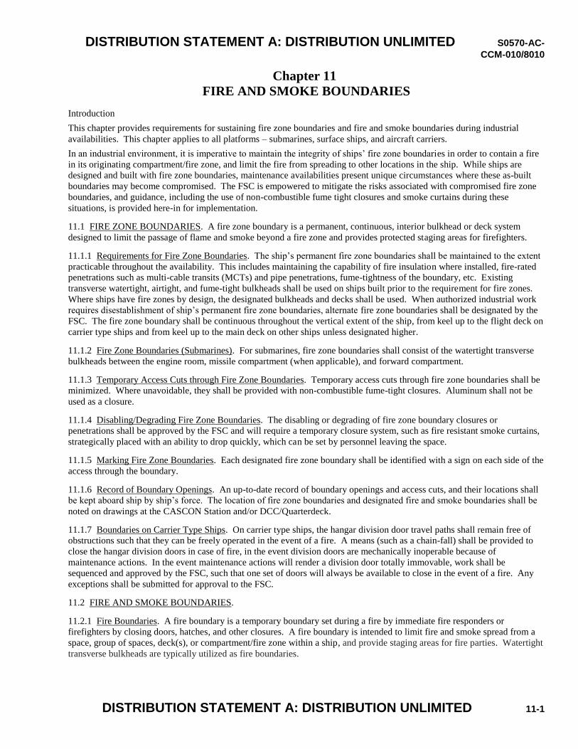
DISTRIBUTION STATEMENT A: DISTRIBUTION UNLIMITED S0570-AC-
CCM-010/8010
DISTRIBUTION STATEMENT A: DISTRIBUTION UNLIMITED 11-1
Chapter 11 FIRE AND SMOKE BOUNDARIES
Introduction
This chapter provides requirements for sustaining fire zone boundaries and fire and smoke boundaries during industrial
availabilities. This chapter applies to all platforms – submarines, surface ships, and aircraft carriers.
In an industrial environment, it is imperative to maintain the integrity of ships’ fire zone boundaries in order to contain a fire
in its originating compartment/fire zone, and limit the fire from spreading to other locations in the ship. While ships are
designed and built with fire zone boundaries, maintenance availabilities present unique circumstances where these as-built
boundaries may become compromised. The FSC is empowered to mitigate the risks associated with compromised fire zone
boundaries, and guidance, including the use of non-combustible fume tight closures and smoke curtains during these
situations, is provided here-in for implementation.
11.1 FIRE ZONE BOUNDARIES. A fire zone boundary is a permanent, continuous, interior bulkhead or deck system
designed to limit the passage of flame and smoke beyond a fire zone and provides protected staging areas for firefighters.
11.1.1 Requirements for Fire Zone Boundaries. The ship’s permanent fire zone boundaries shall be maintained to the extent
practicable throughout the availability. This includes maintaining the capability of fire insulation where installed, fire-rated
penetrations such as multi-cable transits (MCTs) and pipe penetrations, fume-tightness of the boundary, etc. Existing
transverse watertight, airtight, and fume-tight bulkheads shall be used on ships built prior to the requirement for fire zones.
Where ships have fire zones by design, the designated bulkheads and decks shall be used. When authorized industrial work
requires disestablishment of ship’s permanent fire zone boundaries, alternate fire zone boundaries shall be designated by the
FSC. The fire zone boundary shall be continuous throughout the vertical extent of the ship, from keel up to the flight deck on
carrier type ships and from keel up to the main deck on other ships unless designated higher.
11.1.2 Fire Zone Boundaries (Submarines). For submarines, fire zone boundaries shall consist of the watertight transverse
bulkheads between the engine room, missile compartment (when applicable), and forward compartment.
11.1.3 Temporary Access Cuts through Fire Zone Boundaries. Temporary access cuts through fire zone boundaries shall be
minimized. Where unavoidable, they shall be provided with non-combustible fume-tight closures. Aluminum shall not be
used as a closure.
11.1.4 Disabling/Degrading Fire Zone Boundaries. The disabling or degrading of fire zone boundary closures or
penetrations shall be approved by the FSC and will require a temporary closure system, such as fire resistant smoke curtains,
strategically placed with an ability to drop quickly, which can be set by personnel leaving the space.
11.1.5 Marking Fire Zone Boundaries. Each designated fire zone boundary shall be identified with a sign on each side of the
access through the boundary.
11.1.6 Record of Boundary Openings. An up-to-date record of boundary openings and access cuts, and their locations shall
be kept aboard ship by ship’s force. The location of fire zone boundaries and designated fire and smoke boundaries shall be
noted on drawings at the CASCON Station and/or DCC/Quarterdeck.
11.1.7 Boundaries on Carrier Type Ships. On carrier type ships, the hangar division door travel paths shall remain free of
obstructions such that they can be freely operated in the event of a fire. A means (such as a chain-fall) shall be provided to
close the hangar division doors in case of fire, in the event division doors are mechanically inoperable because of
maintenance actions. In the event maintenance actions will render a division door totally immovable, work shall be
sequenced and approved by the FSC, such that one set of doors will always be available to close in the event of a fire. Any
exceptions shall be submitted for approval to the FSC.
11.2 FIRE AND SMOKE BOUNDARIES.
11.2.1 Fire Boundaries. A fire boundary is a temporary boundary set during a fire by immediate fire responders or
firefighters by closing doors, hatches, and other closures. A fire boundary is intended to limit fire and smoke spread from a
space, group of spaces, deck(s), or compartment/fire zone within a ship, and provide staging areas for fire parties. Watertight
transverse bulkheads are typically utilized as fire boundaries.
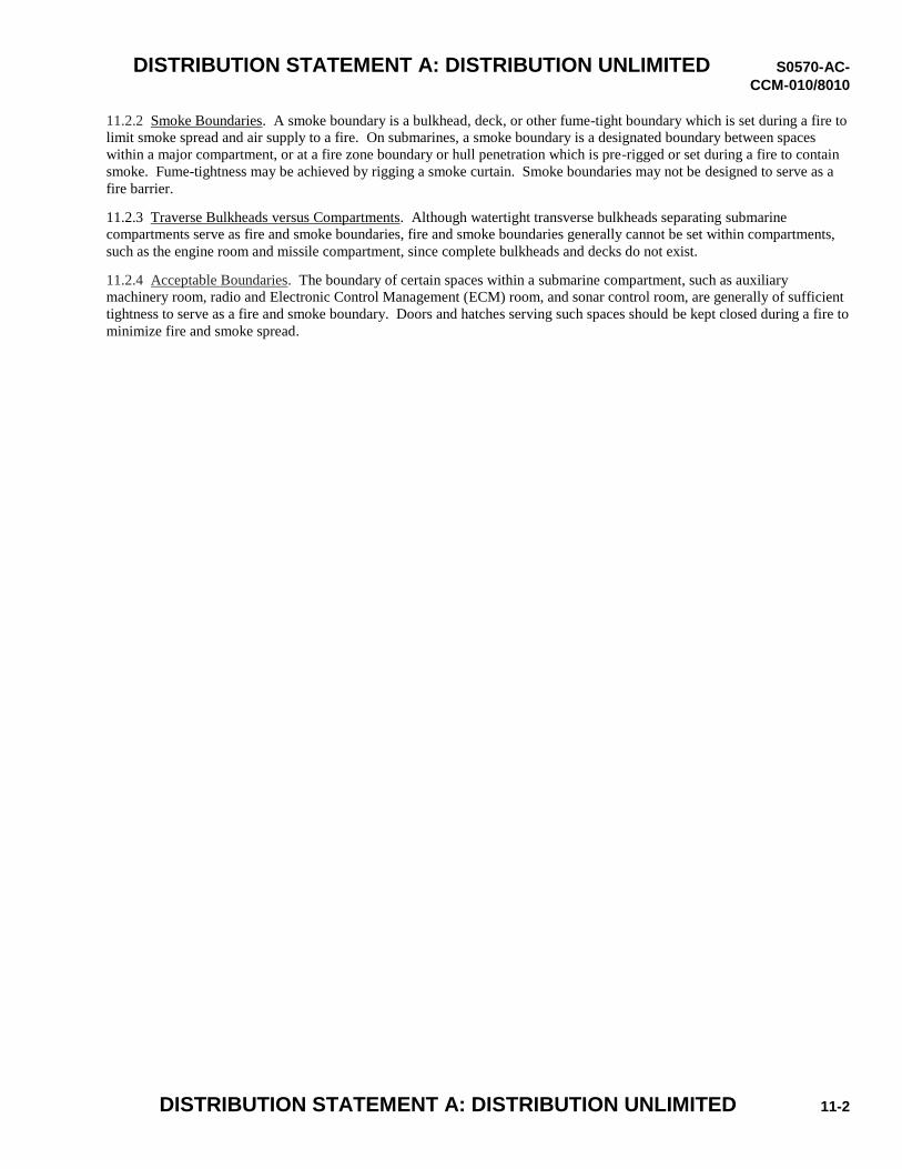
DISTRIBUTION STATEMENT A: DISTRIBUTION UNLIMITED S0570-AC-
CCM-010/8010
DISTRIBUTION STATEMENT A: DISTRIBUTION UNLIMITED 11-2
11.2.2 Smoke Boundaries. A smoke boundary is a bulkhead, deck, or other fume-tight boundary which is set during a fire to
limit smoke spread and air supply to a fire. On submarines, a smoke boundary is a designated boundary between spaces
within a major compartment, or at a fire zone boundary or hull penetration which is pre-rigged or set during a fire to contain
smoke. Fume-tightness may be achieved by rigging a smoke curtain. Smoke boundaries may not be designed to serve as a
fire barrier.
11.2.3 Traverse Bulkheads versus Compartments. Although watertight transverse bulkheads separating submarine
compartments serve as fire and smoke boundaries, fire and smoke boundaries generally cannot be set within compartments,
such as the engine room and missile compartment, since complete bulkheads and decks do not exist.
11.2.4 Acceptable Boundaries. The boundary of certain spaces within a submarine compartment, such as auxiliary
machinery room, radio and Electronic Control Management (ECM) room, and sonar control room, are generally of sufficient
tightness to serve as a fire and smoke boundary. Doors and hatches serving such spaces should be kept closed during a fire to
minimize fire and smoke spread.
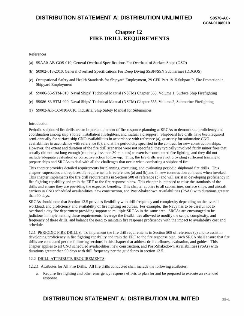
DISTRIBUTION STATEMENT A: DISTRIBUTION UNLIMITED S0570-AC-
CCM-010/8010
DISTRIBUTION STATEMENT A: DISTRIBUTION UNLIMITED 12-1
Chapter 12 FIRE DRILL REQUIREMENTS
References
(a) S9AA0-AB-GOS-010, General Overhaul Specifications For Overhaul of Surface Ships (GSO)
(b) S0902-018-2010, General Overhaul Specifications For Deep Diving SSBN/SSN Submarines (DDGOS)
(c) Occupational Safety and Health Standards for Shipyard Employment, 29 CFR Part 1915 Subpart P, Fire Protection in
Shipyard Employment
(d) S9086-S3-STM-010, Naval Ships’ Technical Manual (NSTM) Chapter 555, Volume 1, Surface Ship Firefighting
(e) S9086-S3-STM-020, Naval Ships’ Technical Manual (NSTM) Chapter 555, Volume 2, Submarine Firefighting
(f) S9002-AK-CC-010/6010, Industrial Ship Safety Manual for Submarines
Introduction
Periodic shipboard fire drills are an important element of fire response planning at SRCAs to demonstrate proficiency and
coordination among ship’s force, installation firefighters, and mutual aid support. Shipboard fire drills have been required
semi-annually for surface ship CNO availabilities in accordance with reference (a), quarterly for submarine CNO
availabilities in accordance with reference (b), and at the periodicity specified in the contract for new construction ships.
However, the extent and duration of the fire drill scenarios were not specified, they typically involved fairly minor fires that
usually did not last long enough (routinely less than 30 minutes) to exercise coordinated fire fighting, and they did not
include adequate evaluation or corrective action follow-up. Thus, the fire drills were not providing sufficient training to
prepare ships and SRCAs to deal with all the challenges that occur when combating a shipboard fire.
This chapter provides detailed requirements for planning, executing, and evaluating periodic shipboard fire drills. This
chapter supersedes and replaces the requirements in references (a) and (b) and in new construction contracts when invoked.
This chapter implements the fire drill requirements in Section 508 of reference (c) and will assist in developing proficiency in
fire fighting capability and train the ERT to the fire response plans. This chapter is intended to raise the standards of the
drills and ensure they are providing the expected benefits. This chapter applies to all submarines, surface ships, and aircraft
carriers in CNO scheduled availabilities, new construction, and Post-Shakedown Availabilities (PSAs) with durations greater
than 90 days.
SRCAs should note that Section 12.5 provides flexibility with drill frequency and complexity depending on the overall
workload, and proficiency and availability of fire fighting resources. For example, the Navy has to be careful not to
overload a city fire department providing support to multiple SRCAs in the same area. SRCAs are encouraged to be
judicious in implementing these requirements, leverage the flexibilities allowed to modify the scope, complexity, and
frequency of these drills, and balance the need to maintain fire response proficiency with the impact to availability cost and
schedule.
12.1 PERIODIC FIRE DRILLS. To implement the fire drill requirements in Section 508 of reference (c) and to assist in
developing proficiency in fire fighting capability and train the ERT to the fire response plan, each SRCA shall ensure that fire
drills are conducted per the following sections in this chapter that address drill attributes, evaluation, and guides. This
chapter applies to all CNO scheduled availabilities, new construction, and Post-Shakedown Availabilities (PSAs) with
durations greater than 90 days with drill frequency per the guidelines in section 12.5.
12.2 DRILL ATTRIBUTE REQUIREMENTS.
12.2.1 Attributes for All Fire Drills. All fire drills conducted shall include the following attributes:
a. Require fire fighting and other emergency response efforts to plan for and be prepared to execute an extended
response.
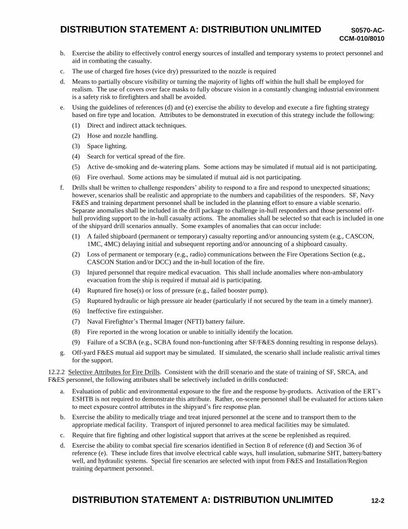
DISTRIBUTION STATEMENT A: DISTRIBUTION UNLIMITED S0570-AC-
CCM-010/8010
DISTRIBUTION STATEMENT A: DISTRIBUTION UNLIMITED 12-2
b. Exercise the ability to effectively control energy sources of installed and temporary systems to protect personnel and
aid in combating the casualty.
c. The use of charged fire hoses (vice dry) pressurized to the nozzle is required
d. Means to partially obscure visibility or turning the majority of lights off within the hull shall be employed for
realism. The use of covers over face masks to fully obscure vision in a constantly changing industrial environment
is a safety risk to firefighters and shall be avoided.
e. Using the guidelines of references (d) and (e) exercise the ability to develop and execute a fire fighting strategy
based on fire type and location. Attributes to be demonstrated in execution of this strategy include the following:
(1) Direct and indirect attack techniques.
(2) Hose and nozzle handling.
(3) Space lighting.
(4) Search for vertical spread of the fire.
(5) Active de-smoking and de-watering plans. Some actions may be simulated if mutual aid is not participating.
(6) Fire overhaul. Some actions may be simulated if mutual aid is not participating.
f. Drills shall be written to challenge responders’ ability to respond to a fire and respond to unexpected situations;
however, scenarios shall be realistic and appropriate to the numbers and capabilities of the responders. SF, Navy
F&ES and training department personnel shall be included in the planning effort to ensure a viable scenario.
Separate anomalies shall be included in the drill package to challenge in-hull responders and those personnel off-
hull providing support to the in-hull casualty actions. The anomalies shall be selected so that each is included in one
of the shipyard drill scenarios annually. Some examples of anomalies that can occur include:
(1) A failed shipboard (permanent or temporary) casualty reporting and/or announcing system (e.g., CASCON,
1MC, 4MC) delaying initial and subsequent reporting and/or announcing of a shipboard casualty.
(2) Loss of permanent or temporary (e.g., radio) communications between the Fire Operations Section (e.g.,
CASCON Station and/or DCC) and the in-hull location of the fire.
(3) Injured personnel that require medical evacuation. This shall include anomalies where non-ambulatory
evacuation from the ship is required if mutual aid is participating.
(4) Ruptured fire hose(s) or loss of pressure (e.g., failed booster pump).
(5) Ruptured hydraulic or high pressure air header (particularly if not secured by the team in a timely manner).
(6) Ineffective fire extinguisher.
(7) Naval Firefighter’s Thermal Imager (NFTI) battery failure.
(8) Fire reported in the wrong location or unable to initially identify the location.
(9) Failure of a SCBA (e.g., SCBA found non-functioning after SF/F&ES donning resulting in response delays).
g. Off-yard F&ES mutual aid support may be simulated. If simulated, the scenario shall include realistic arrival times
for the support.
12.2.2 Selective Attributes for Fire Drills. Consistent with the drill scenario and the state of training of SF, SRCA, and
F&ES personnel, the following attributes shall be selectively included in drills conducted:
a. Evaluation of public and environmental exposure to the fire and the response by-products. Activation of the ERT’s
ESHTB is not required to demonstrate this attribute. Rather, on-scene personnel shall be evaluated for actions taken
to meet exposure control attributes in the shipyard’s fire response plan.
b. Exercise the ability to medically triage and treat injured personnel at the scene and to transport them to the
appropriate medical facility. Transport of injured personnel to area medical facilities may be simulated.
c. Require that fire fighting and other logistical support that arrives at the scene be replenished as required.
d. Exercise the ability to combat special fire scenarios identified in Section 8 of reference (d) and Section 36 of
reference (e). These include fires that involve electrical cable ways, hull insulation, submarine SHT, battery/battery
well, and hydraulic systems. Special fire scenarios are selected with input from F&ES and Installation/Region
training department personnel.
DISTRIBUTION STATEMENT A: DISTRIBUTION UNLIMITED S0570-AC-
CCM-010/8010
DISTRIBUTION STATEMENT A: DISTRIBUTION UNLIMITED 12-3
e. An integrated off-hull rehabilitation and staging station for all firefighters (SF, F&ES, and other ships’ crew) shall
be evaluated as part of the fire response plan and exercised during the drill if enough responders (SF, F&ES, other
responders) are available.
f. Per references (d) and (e), exercise the following fire fighting strategy elements:
(1) Search and rescue.
(2) Establish tenable access/egress to hull.
(3) Protection of exposures (e.g., ship superstructure, antenna arrays, etc.), submarine SHT, and Radar Absorbent
Material (RAM).
(4) Confinement of fire (boundary protection).
12.3 DRILL EVALUATION. Consistent with the scenario, and using as guidelines the application of the effective fire
fighting principles and the EFRS standard attributes in the SRCA’s FRP, and in appendices A and C, the SRCA, SF, and
F&ES drill team shall evaluate the following fire fighting and emergency response capabilities, as applicable.
a. Performance by emergency and technical management personnel in providing technical assistance, advice, and
logistic support to response personnel.
b. Emergency medical triage and treatment of injured personnel. Transport of injured personnel to area medical
facilities may be simulated.
c. Ability of the response team to clear temporary service lines from access points, and isolate sources of energy from
the scene of the fire, including electrical power, hydraulics, and high pressure air and when applicable, ordnance and
fuel systems.
d. Adequacy and effective execution of the incident management structure.
e. Plan to deploy mutual aid support in an orderly, effective manner, including fire lane discipline before and during
the response, and off-hull staging of additional responding resources.
f. The ability to replenish fire fighting and other logistical support that arrives at the scene. Periodically demonstrate
the ability to recharge expended SCBA cylinders.
g. Coordination between the SRCA, SF, other ship crews, and installation F&ES responders. This shall include
firefighter accountability procedures in the hull/IDLH zone and the level of integrated response.
h. The team’s ability to develop and execute an integrated fire fighting strategy based on fire type and location and the
effectiveness of the techniques employed.
i. The team’s ability to respond to the drill anomalies.
j. The effectiveness of the integrated rehabilitation area(s) and off-hull staging area(s).
12.4 DRILL TEAM, GUIDES, AND POST-EVENT EVALUATION.
12.4.1 SRCA Drill Team. The SRCA shall establish a team of trained personnel that have the requisite experience and
knowledge to prepare for and execute fire casualty drills. These positions shall include drill initiators, simulation providers,
safety observers, and drill evaluators. The Ship, F&ES, and, where practical, the ISIC/TYCOM, SRCA Rep, and
Installation/Region training department personnel shall be included as drill evaluation team members.
12.4.2 Drill Guide. A drill guide integrating SF, SRCA, and F&ES shall be prepared using the guidelines in appendix F.
The FSC executing drill control and evaluation and an F&ES member will review the drill guide. On NPWs, the drill guide
review shall also include the Nuclear Chief Test Engineer (CTE) and Chief Refueling Engineer (CRE). The reviewed drill
guide will be submitted to the ship’s Commanding Officer and the shipyard Operations Officer (Code 300) (or for other
SRCAs, the equivalent senior manager) for approval.
12.4.3 Drill Termination. Provisions shall be in place to terminate the drill in the event there is an actual emergency on the
ship or if personnel or ship systems are placed in an unsafe condition.
12.4.4 Response to Actual Casualty. Provisions shall be in place to respond to any actual casualty at the SRCA that would
require emergency response during the drill. This may include terminating the drill if the casualty is significant.
12.4.5 Realistic Fire Scenario. Effort shall be made to produce the most realistic fire scenario possible, without risking
personnel injury or equipment damage. For example, vision may be partially obscured by devices simulating smoke (these
DISTRIBUTION STATEMENT A: DISTRIBUTION UNLIMITED S0570-AC-
CCM-010/8010
DISTRIBUTION STATEMENT A: DISTRIBUTION UNLIMITED 12-4
devices shall only partially obscure vision and shall be provided by the drill team), and access to areas might be prevented by
monitors to simulate challenges from the heat and to evaluate the capability to execute alternate fire fighting strategies. Use
of live fire fighting agents (charged hose or portable fire extinguishers), and dressing in full fire fighting ensemble should be
the standard on all drills to replicate the challenges of moving through the ship. Safety observation for indications of heat
stress is required. When hoses are charged, the water supply valve shall be shut to avoid a large water spill should a nozzle
be accidently opened. Portable fire extinguishers shall be properly controlled so that an inadvertent discharge during the drill
does not occur.
12.4.6 Minimize Simulations. Simulations for the casualty drill response shall be minimized. This will require advance pre-
drill actions and additional safety observers during the drill. For example, it is expected that fire hoses will be pressurized
during the drill. To do that safely, and to ensure water is not inadvertently released into the ship, hoses shall be tested
(validate all hose testing conducted and documented per Planned Maintenance System (PMS) requirements) prior to the drill,
safety observers assigned, and nozzle bails shall be temporarily secured but with materials that can be easily removed by
hand (e.g., Velcro®). Personnel wearing SCBAs shall be “on-air” when operating in the drill scenario’s IDLH zone. Ship
and temporary systems (e.g., ship’s service hydraulics, affected electrical distribution systems, ship and aviation fuel and lube
oil, temporary high pressure air) that can be secured, consistent with ship and plant safety, shall be operated in the same
manner as they would be during an actual casualty.
12.4.7 SRCA Response. The response by SRCA personnel should be as realistic as possible. For example, the affected
ship’s project team including the FSC and Joint Test and Refueling Groups (JTG/JRG) members (where applicable), shall
respond to the drill as they would for an actual casualty. Accordingly, the FSC from the affected ship shall not be part of the
drill team. A FSC from another ship or alternate FSC members from the affected ship augmented by an F&ES member shall
be used in this capacity. Personnel exemptions from the drill shall be rare and when required, minimized. Exemption
requests shall be submitted by the cognizant SRCA manager and approved by the evaluation FSC.
a. To the extent practicable, action to support a realistic response shall apply to and include other personnel expected to
respond to casualties. This includes, but is not limited to, Chief Test and Refueling Engineers (where applicable)
and other project personnel, SRCA middle managers (Engineering (e.g., Code 200/2300) Division Heads, Safety and
Health (Code 106) personnel, shop superintendents, etc.). The SRCA shall ensure senior qualified personnel are
assigned to the drill team and balance these assignments with the need to ensure senior qualified personnel are also
available to respond to the drill.
b. Activation of the RERO (NPW only) shall not normally occur during these drills. This includes response by the
RERO on-scene incident commander and his team. However, either discussion on action to activate the RERO or
simulate RERO activation is expected to occur to ensure personnel demonstrate familiarity with this action.
c. To increase the training benefit of these drills, the SRCA may coordinate with the Installation and Navy Region,
where applicable, to activate the respective EOC/ROC as part of the fire response.
12.4.8 Drill Hotwash. A drill hotwash shall be conducted by the response team immediately after drill termination. During
the hotwash, the drill evaluation team should interject, if necessary, to ensure that the major comments from the drill are
captured.
12.4.9 Drill Evaluation. Following the response team hotwash, the drill evaluation team shall meet to compile any additional
comments observed by the drill evaluators. The drill evaluation team should go through the expected and actual actions and
base any comments on the gaps between the two. The drill evaluation team shall reach agreement on the major comments
and the overall grade and evaluate the accomplishment of the stated objectives for the drill.
12.4.10 Written Report. A written report including corrective actions with due dates and recommendations for improvement
shall be produced and formally issued by the SRCA following the drill. This report shall include the comments from the
response team hotwash and those from the evaluating FSC augmented with an F&ES member.
12.4.11 Action for an Unsatisfactory Grade. Another drill shall be conducted once corrective action to address the
significant findings of the unsatisfactory drill is completed. This corrective action plan shall include the expected date for the
subsequent drill. For significant findings, the SRCA shall consider additional temporary measures to mitigate fire hazards
relevant to the finding(s) until corrective action is taken and re-evaluated by the follow-up drill. This drill may be limited in
scope but as a minimum will reevaluate the weak areas noted, shall be accomplished as soon as possible after corrective
action is completed but no later than 30 days after the unsatisfactory drill.
DISTRIBUTION STATEMENT A: DISTRIBUTION UNLIMITED S0570-AC-
CCM-010/8010
DISTRIBUTION STATEMENT A: DISTRIBUTION UNLIMITED 12-5
12.4.12 Submitting the Report. The Region/Installation training department personnel Fire Chief (N30) will be provided a
copy of the drill report.
12.4.13 Fire Response Capabilities during the Drill. The SRCA and the Region/Installation shall ensure the SRCA fire
response capabilities are not significantly reduced to meet the all hazard F&ES response mission during a drill.
12.4.14 Duration of Drills. While these drills should have durations based on response actions and the achievement of stated
drill objectives rather than elapsed time, experience by NSYs in conducting fire drills per the attributes of this chapter
indicates that drill durations should be approximately 30 - 45 minutes.
12.5 DRILL FREQUENCY. Fire drills shall be conducted every 90 days for submarines and every 180 days for surface
ships in CNO scheduled availabilities (scheduled for greater than 6 months duration). For ships under construction, drills
meeting the attributes of this chapter shall be conducted every 6 months up to the 50 percent completion of the ship and every
90 days thereafter on submarines and every 180 days thereafter on surface ships. For CNO availabilities scheduled for less
than 6 months but greater than 90 days (or when reference (f) is invoked for submarines), one drill meeting the requirements
of this chapter shall be conducted. This drill shall occur as soon as practical but not later than 1 month after the start of the
availability.
12.5.1 Burden of Requirements. There may be occasions where the number of ships in CNO scheduled availabilities or
under construction at a SRCA is high enough that invoking all requirements of this chapter would create an excessive burden
on the SRCA’s fire safety and emergency management organizations and F&ES. In those cases, some attributes of this
chapter may be relaxed as formally proposed and documented by the SRCA to the NSRO, RMC, or SUPSHIP and subject to
the following:
a. The decision to relax these requirements will be done after considering the state of training and readiness of the
on-scene response personnel including SF, SRCA, and F&ES.
b. At least one drill each quarter at each SRCA will meet the requirements of this chapter.
c. For submarines in CNO scheduled availabilities scheduled for greater than 12 months, one-half of the quarterly
drills for each submarine shall meet the requirements of this chapter.
d. For CVN Refueling Complex Overhauls (RCOHs), every drill shall meet the requirements of this chapter.
12.5.2 Back-shift Drill. At least one back-shift drill per year shall be conducted at each SRCA to exercise and evaluate the
FRP throughout the day.

DISTRIBUTION STATEMENT A: DISTRIBUTION UNLIMITED S0570-AC-
CCM-010/8010
DISTRIBUTION STATEMENT A: DISTRIBUTION UNLIMITED 12-6
THIS PAGE INTENTIONALLY LEFT BLANK.
DISTRIBUTION STATEMENT A: DISTRIBUTION UNLIMITED S0570-AC-
CCM-010/8010
DISTRIBUTION STATEMENT A: DISTRIBUTION UNLIMITED 13-1
Chapter 13 MAJOR FIRE DRILL REQUIREMENTS
References
(a) S9086-S3-STM-010, Naval Ships’ Technical Manual (NSTM) Chapter 555, Volume 1, Surface Ship Firefighting
(b) S9086-S3-STM-020, Naval Ships’ Technical Manual (NSTM) Chapter 555, Volume 2, Submarine Firefighting
(c) S9211-05-MMA-000/(C), Radiological Emergency Planning Manual for the Naval Nuclear Propulsion Program
(d) NAVSEA 389-0288, Radiological Controls
Introduction
As discussed in chapter 12, periodic shipboard fire drills in ships undergoing availabilities are important to demonstrate
proficiency and coordination among ship’s force, installation firefighters, and mutual aid support in responding to shipboard
fires that may occur during industrial work. However, the drills were never required by NAVSEA to test or evaluate the full
emergency response capabilities of the SRCAs that would be needed to combat a major fire. Thus, the criteria and
requirements were developed to conduct a major shipboard fire drill at each SRCA annually and to have them formally
evaluated. This action is considered essential to ensure SRCAs building and repairing Navy ships can rapidly respond to a
major fire casualty and successfully bring it under control to minimize damage and prevent loss of the ship.
This chapter specifies the requirement to conduct an annual major fire drill that comprehensively evaluates the ability of a
SRCA to execute its full Fire Response Plan (FRP) and Emergency Response capability, and provides the attributes, guides,
and criteria for planning and executing the drills. This chapter applies to all SRCAs and involves all Navy ships –
submarines, surface ships, and aircraft carriers, and requires formal reports for sharing lessons learned and ensuring all
SRCAs benefit from the drills. This chapter builds on the foundation of the periodic fire drills required by Chapter 12, and
requires coordination with NAVSEA, CNRMC, CNIC, and applicable TYCOM to schedule and execute.
NAVSEA recognizes this is a large undertaking and the major drills will have an impact on cost and production schedules.
SRCAs are encouraged to be judicious and careful in their planning to balance the objectives of learning and demonstrating
capabilities with minimizing cost and schedule impact. Some considerations included in this chapter that should be taken
into account are as follows:
- For nuclear capable SRCAs, per section 13.3.10 of this chapter, the major fire drill can satisfy the drill requirement
of Article 109 in reference (d) once every two years if conducted on a nuclear powered warship (or in propulsion
spaces for CVNs) per Section 13.3.10, and thus not add overall cost to the Navy since the Article 109 drill must be
conducted per reference (d). In the year where it would not count, the SRCA could elect to conduct the drill on a
non-nuclear ship or outside the propulsion spaces of CVNs if available, and the overall cost would be less.
- Per section 13.3.11 of this chapter, private repair SRCAs located in the same region and supported by the same fire
department (e.g., Norfolk and San Diego) may satisfy the annual requirement by conducting the drill at one SRCA,
while the others observe and/or participate under the guidance and approval of the RMC. To ensure all SRCAs
experience the drill, it should be rotated among them each year.
SRCAs are encouraged to recommend additional ideas to NAVSEA, CNRMC and CNIC to ensure the Navy achieves
maximum benefit from these drills while minimizing impact to ship availabilities.
13.1 DRILL ATTRIBUTE REQUIREMENTS. A periodic comprehensive evaluation of a SRCA’s FRP is an essential
element to protect against a major shipboard fire during repair or construction. At least annually at each SRCA, one fire drill
shall be of sufficient scope and magnitude to:
a. Activate the full ERT, including manning the EOC and the ROC (if applicable), and for NPWs, the RERO and the
ECC. For CVNs, the drill does not require RERO activation if conducted outside of the propulsion spaces. It does,
however, require activation of the cognizant ERT team branches/sections in the ECC/EOC.
b. Require fire fighting and other emergency response efforts to plan for, and be prepared to, execute an extended
response.
DISTRIBUTION STATEMENT A: DISTRIBUTION UNLIMITED S0570-AC-
CCM-010/8010
DISTRIBUTION STATEMENT A: DISTRIBUTION UNLIMITED 13-2
c. Require evaluation of public and environmental exposure to the fire and the response by-products.
d. Exercise the ability to medically triage and treat at least two simulated injured personnel at the scene, and/or
transport them to appropriate medical facilities. A sketch or diagram of the injured personnel (treated, and if left
untreated or improperly treated) shall be included in the drill package. The injured person’s medical condition,
including vital signs such as blood pressure, pulse, respiration rate, a description of any wounds, as well as other
necessary medical information, shall be provided.
e. Require that fire fighting and other logistics support equipment that arrives at the scene be replenished.
f. Exercise the ability to effectively control energy sources of installed and temporary systems to protect personnel,
and aid in combating the casualty.
g. Exercise the ability to combat special fire scenarios identified in Section 8 of reference (a) or Section 36 of reference
(b). These include fires that involve hangar fires involving aircraft, de-smoking amphibious ship well decks,
electrical cable ways, hull insulation, Special Hull Treatment (SHT), submarine battery/battery wells, lithium
batteries, chimney space, ordnance/magazines, and hydraulic systems. Most, if not all, of these special scenarios
would likely be encountered in a major shipboard fire, so response to these shall be included in this annual drill
scenario based on its simulated severity and location. All of these shall be included in the ERT training program and
be evaluated regularly during the more frequently conducted drills specified in chapter 12. The use of charged fire
hoses (vice dry) pressurized to the nozzle is required. A means to include compromised visibility within the hull
shall also be employed for realism.
h. Using the guidelines of references (a) or (b), exercise the ability to develop and execute a fire fighting strategy based
on fire type and location for the following attributes:
(1) Direct and indirect attack techniques.
(2) Hose and nozzle handling.
(3) Space lighting.
(4) Search for vertical spread of the fire.
(5) Active de-smoking and de-water plans and execution.
(6) Search and rescue.
(7) Fire overhaul.
(8) Establish tenable access/egress to hull.
(9) Protection of exposures, SHT (submarines), and RAM, PCMS (surface ships).
(10) Confinement of fire (fire boundary protection).
i. The drill shall be written to challenge responders’ ability to respond to a major fire and respond to unexpected
situations. Separate anomalies shall be included in the drill package to challenge in-hull responders, on-scene
responders, each branch in the ECC, and the EOC/ROC. Some examples of anomalies that can occur include:
(1) A failed shipboard (permanent or temporary) casualty reporting and/or announcing system (e.g., CASCON,
1MC, 4MC) delaying initial and subsequent reporting and/or announcing of a shipboard casualty.
(2) Loss of permanent or temporary (e.g., radio) communications between the Fire Operations Section (e.g.,
CASCON Station and/or DCC) and the in-hull location of the fire.
(3) Injured personnel that require medical evacuation. This shall include anomalies where non-ambulatory
evacuation from the ship is required.
(4) Ruptured fire hose(s) or loss of pressure (e.g., failed booster pump).
(5) Ruptured hydraulic or high pressure air header (particularly if not secured by the team in a timely manner).
(6) Ineffective CO2 extinguisher.
(7) NFTI battery failure.
(8) Fire reported in the wrong location or unable to initially identify the location.
(9) Compromise or loss of a primary bridge line.
(10) Failure of an SCBA (e.g., SCBA found non-functioning after SF donning, resulting in response delays).
DISTRIBUTION STATEMENT A: DISTRIBUTION UNLIMITED S0570-AC-
CCM-010/8010
DISTRIBUTION STATEMENT A: DISTRIBUTION UNLIMITED 13-3
j. Anomalies shall be selected so that each is regularly exercised during this drill along with the periodic drills required
by chapter 12.
k. Off-yard F&ES mutual aid support may be simulated. If simulated, the scenario shall include realistic arrival times
for the support.
l. Public affairs.
(1) Include a simulated press availability or conference. This shall be conducted after drill termination but on the
same day.
(2) For each drill, there shall be a number of simulated public inquiries from outside agencies, news media
(newspapers, television, and radio stations), and private citizens. These shall include news outlets at the local
and national (broadcast and cable) levels. The drill team shall include members as role players for this
simulated media and private inquiries, and measures shall be in place to prevent actual information exchange.
(3) The number of press inquiries and their complexity shall be prepared to challenge the state of training of the
installation’s public affairs organization and is expected to increase over time as this capability improves.
m. Outside agency participation. The drill shall include simulation for information exchange with outside agencies that
would be expected to be involved during an actual casualty. These include local Coast Guard and state emergency
management, health, environment and law enforcement agencies. The drill package shall include the means for
simulating and controlling interface with these agencies. It is appropriate to occasionally exercise actual exchange
with these agencies rather than it be simulated. In those cases, the drill package, when submitted to NAVSEA
(CNRMC for RMCs) and CNIC, shall identify the specific degree of involvement by any of these agencies and
control measures taken to ensure that it is clearly understood that their involvement is an exercise.
n. Require sustained and accurate communication of the event with the ECC, the Installation EOC, and the ROC.
o. For drills where the simulated fire is confined to non-propulsion spaces, the drill package shall be written to require
expected actions in the engine room (e.g., watch-standers don breathing protection) in response to the casualty, and
an evaluation of contingency actions to address a potential spread of the fire or its effects (smoke/water) to the
engineering spaces or disruption of services to and from the propulsion plant.
p. An integrated on-scene rehabilitation area(s) and staging station for all firefighters (SF, F&ES, other ships’ crew,
and mutual aid) will be established and exercised.
13.2 DRILL EVALUATION. Drill evaluation shall include the following:
a. An overall assessment of the effective application of the fire fighting principles and accomplishment of the EFRS
attribute standards in the SRCA’s FRP, and appendices A and C of this manual.
b. Performance by the ECC and ROC/EOC team in providing technical assistance and advice to the on-scene Incident
Management Structure, logistics support, liaison with state and local emergency management officials, and
coordination and communications with cognizant Naval Commands (NAVSEA, NAVSEA 08, CNIC, CNRMC, and
Fleet/TYCOM).
c. Media-related actions.
d. Emergency medical triage, treatment of injured personnel, and transport area.
e. Ability of the response team to clear temporary service lines from access points, and isolate sources of energy from
the scene of the fire, including electrical power, hydraulics, fuels, lubricating oils, and high pressure air.
f. Adequacy and effective use of the incident command post and its designated location.
g. Plan to deploy mutual aid support in an orderly, effective manner, including fire lane discipline before and during
the response and off/ on-scene staging of additional responding resources. If mutual aid is simulated, elements of
the simulated response should be evaluated where practical.
h. Ability to replenish fire fighting equipment, and other required logistics support. This will include a demonstration
of the ability to replenish and recharge expended SCBA cylinders.
i. On-scene coordination between the SRCA’s ERT, SF, other ship crews, F&ES, and mutual aid responders. This
shall include firefighter accountability procedures shipboard and in the IDLH, and the level of integrated response.
j. The team’s ability to develop and execute a fire fighting strategy based on fire type and location for the attributes in
13.1.g and 13.1.h.
DISTRIBUTION STATEMENT A: DISTRIBUTION UNLIMITED S0570-AC-
CCM-010/8010
DISTRIBUTION STATEMENT A: DISTRIBUTION UNLIMITED 13-4
k. The ERT’s ability to respond to the drill anomalies.
l. The effectiveness of the integrated rehabilitation area(s) and on-scene staging area.
13.3 DRILL TEAM, GUIDES, AND POST-EVENT EVALUATION.
13.3.1 Major Fire Drill Team. The SRCA shall establish a team of trained personnel that have the requisite experience and
knowledge to prepare for, and execute, extended fire drills. These positions shall include drill initiators, simulation
providers, safety observers, and drill evaluators. This team will supplement and be integrated with the drill controllers for
radiological emergency response drills (NPWs only). The Ship and Installation/Region training department personnel shall
be included as part of the drill team.
13.3.2 Drill Evaluators. Senior drill evaluators shall be assigned to evaluate the performance of in-hull responders, the
Incident Command Post, on-scene responders, and each branch in the ECC and the EOC/ROC. Evaluators from the SRCA,
ship, and Region/Installation shall be included and led by the senior evaluator from the SRCA. These evaluators shall be
qualified for the senior position being evaluated (e.g., ECC/EOC Director for ECC/EOC, Command and Control, Public
Affairs Officer (PAO), Liaison Branch/Section, In-hull Incident Command, Fire Chief for In-Hull Fire Fighting and
Integrated Operations Section). Prior to the drill, each evaluator shall review the drill package and identify the expected
response actions of the team they are evaluating. These expected actions shall include expected times by which actions
should be taken and expected response to anomalies. In addition, appropriate evaluators shall tour the selected ship before
the drill and pre-drill brief. Prior to the drill, the lead evaluator shall conduct an interactive brief with the entire drill team to
evaluate the team’s readiness to evaluate drill responder performance.
13.3.3 Drill Guide. A drill guide shall be prepared using the following guidelines. For NPWs, the drill guide shall also be
prepared using the guidelines in reference (c).
13.3.3.1 Provide a realistic scenario that establishes the following:
a. A drill timeline that includes a time-based description of the spread of the fire that will depend on the timeliness of
response actions. For example, fires in wireways may spread to the next compartment unless a fire hose is brought
to bear within 5 minutes.
b. A set of initial conditions.
c. Initiation point and cause of the fire.
d. Post initiation anomalies, with a set of special scenarios identified in reference (a) or (b) included.
e. Alternate outcomes based on the team’s response to the casualty. It is expected that the drill’s complexity will cause
the drill to be an extended fire response event.
13.3.3.2 The drill guide should list a set of objectives for each drill. One objective shall be evaluation of the effectiveness of
actions taken to address significant drill findings noted during fire drills since the prior annual drill.
13.3.3.3 The drill guide shall address the progress of the casualty, and its effect on ship and ship’s systems conditions. This
section will include assumptions and calculations (if any were employed) used to determine the spread of the fire and its
containment/extinguishment.
13.3.3.4 The guide shall include a section to document the response performance for those attributes included in appendix C
of this manual. These attributes collectively are referred to as the Engineered Fire Response Strategy (EFRS), and the drill
guide shall evaluate each area.
13.3.3.5 Provisions shall be in place to terminate the drill in the event there is an actual injury on the ship, or ship systems
are placed in unsafe conditions.
13.3.3.6 Provisions shall be in place to respond to an actual casualty at the SRCA that would require emergency response
during the drill. This may include terminating the drill if the casualty is significant.
13.3.3.7 Effort shall be made to produce the most realistic fire scenario possible, without risking personnel injury or
equipment damage. For example, vision should be impacted by obscurement devices simulating smoke, and access to areas
might be prevented by monitors to simulate challenges from the heat and to evaluate the capability to execute alternate fire
fighting strategies. Use of live fire fighting agents (charged hose or CO2 bottle), and dressing in full fire fighting ensemble
shall be employed to replicate the challenges of moving through the ship. Personnel wearing SCBAs shall be “on-air” when
DISTRIBUTION STATEMENT A: DISTRIBUTION UNLIMITED S0570-AC-
CCM-010/8010
DISTRIBUTION STATEMENT A: DISTRIBUTION UNLIMITED 13-5
operating in the drill scenario’s IDLH. After hoses are charged, the water supply valve shall be shut, to avoid a large water
spill should a nozzle be accidently bumped open.
13.3.3.8 Simulations for the casualty drill response shall be minimized. This will require advanced pre-drill actions and
additional safety observers during the drill. For example, for fire hoses to be safely pressurized, hoses shall be validated to be
within their test periodicity before the drill, and safety observers shall be assigned to ensure water is not released into the ship
inadvertently. Ship and temporary systems (e.g., ship’s service hydraulics, affected electrical distribution systems, ship and
aviation fuel and lube oil, temporary high pressure air that can be secured consistent with ship and plant safety) should be
operated in the same manner as they would be during an actual casualty.
13.3.3.9 Personnel exemptions from the drill shall be rare and when required, minimized. Exemption requests shall be
submitted by the cognizant SRCA manager or fire chief and approved by the evaluation FSC.
13.3.4 Drill Hotwash. A drill hotwash shall be conducted by the response team immediately after drill termination. During
the hotwash, the drill team shall interject, if necessary, to ensure that the major comments from the drill are captured.
13.3.5 Drill Evaluation Team. Following the response team hotwash, the drill evaluation team shall meet to compile any
additional comments observed by the drill evaluators. The drill evaluation team shall go through the expected and actual
actions, and base any comments on the gaps between the two. The drill team shall reach agreement on the major comments
and the overall grade, and for drills evaluated by a CNRMC/NAVSEA and CNIC Evaluation Team, be prepared to brief the
results to the Evaluation Team by 0800 the following day.
13.3.6 Evaluation of Simulated Press Conference/Availability. The drill team shall evaluate the performance of the
simulated press conference/availability.
13.3.7 NAVSEA and CNIC Review. Each SRCA shall submit their approved drill package, endorsed by the respective
Installation/Navy Region Commander (where applicable), to NAVSEA (CNRMC for RMCs), and CNIC for review not later
than six weeks before the scheduled drill date. This shall include assessment guides the SRCA drill team will use to evaluate
drill performance. Private SRCAs shall submit their drill packages via the cognizant SUPSHIP or RMC. Naval Ship Repair
Facility and Japan Regional Maintenance Center (SRF-JRMC) shall submit their drill package to CPF and CNIC.
13.3.8 Drill Brief, Execution, and Debrief Schedule. The SRCA drill team shall provide the drill brief, execution, and
debrief schedule to NAVSEA (CNRMC for RMCs) and CNIC.
13.3.9 Written Evaluations/Reports. Written evaluations/reports including corrective actions and recommendations for
improvement shall be produced and formally issued by the SRCA following the drill. Major deficiencies should be
documented with responsible organizations and completion dates for causal analysis and corrective actions specified. Minor
deficiencies do not require causal analysis, but should be tracked in the SRCA’s Deficiency Reporting and Tracking System,
and responsible organizations shall take appropriate actions to correct minor deficiencies. This report shall be prepared
within 1 month of the drill with distribution to SEA 04, SEA 05, SEA 08 (NPWs only), SEA 09, SEA 07 (Submarines), SEA
21 (Surface Ships), PMS 312 (CVNs), CNIC, CNRMC (Surface Ships), CPF (SRF-JRMC), cognizant ISIC, TYCOM,
NSRO, NRRO and NRMO, UFFC, and Navy Region (N7).
13.3.10 Nuclear Powered Warships. For NPWs, planning, execution and evaluation of the drill shall comply with the
requirements of references (c) and (d). If evaluated with a grade of “satisfactory”, it will satisfy the drill requirement of
Article 109 to reference (d) once every 2 years. For CVNs, the drill must be conducted in the propulsion spaces to satisfy
this requirement.
13.3.11 Non-Nuclear Powered Warships At Private Repair SRCAs. SRCAs located in the same region and supported by the
same fire department (e.g., Norfolk and San Diego) may satisfy the annual requirement by conducting the drill at one SRCA
and the others observe and/or participate under the guidance and approval of the RMC. To ensure all SRCAs experience the
drill, it should be rotated among them each year.
DISTRIBUTION STATEMENT A: DISTRIBUTION UNLIMITED S0570-AC-
CCM-010/8010
DISTRIBUTION STATEMENT A: DISTRIBUTION UNLIMITED 13-6
THIS PAGE INTENTIONALLY LEFT BLANK.
DISTRIBUTION STATEMENT A: DISTRIBUTION UNLIMITED S0570-AC-
CCM-010/8010
DISTRIBUTION STATEMENT A: DISTRIBUTION UNLIMITED 14-1
Chapter 14 SPECIAL SUBMARINE SHIPBOARD FIRE HAZARDS
References
(a) S9086-S3-STM-020, Naval Ships’ Technical Manual (NSTM) Chapter 555, Volume 2, Submarine Firefighting
(b) S9086-G1-STM-010, Naval Ships’ Technical Manual (NSTM) Chapter 223, Volume 1, Submarine Storage Batteries
(c) S6360-AD-HBK-010, Technical Handbook for Special Hull Treatment Maintenance and Repair for Submarines
(d) S6360-AV-MMA-010, Maintenance and Repair Manual for VIRGINIA Class Submarine Special Hull Treatment
Introduction
This chapter is specific to submarines and provides special protection requirements and risk mitigations associated with
submarine battery compartments and charging operations, and fires associated with Special Hull Treatment (SHT) tiles in
drydock. These two instances, specifically, present unique fire hazards and situations presented during industrial
maintenance periods and require additional precautions to mitigate the associated risks. The requirements contained here-in
are consistent with the technical requirements contained in references (a) through (d). Each SRCA that performs submarine
construction and maintenance availabilities is encouraged to develop additional means of mitigating the risks associated with
these unique fire hazards and gain FSC approval for implementing these additional methods.
14.1 GENERAL. Submarines have inherent fire hazards that could result in catastrophic consequences if a fire or casualty
involving these hazards occurs while a submarine is in an industrial availability. Therefore, it is imperative that personnel
who are managing and executing industrial work in and around these hazards are aware of their presence, take prudent
precautions to avert their involvement in a fire, and have knowledge of actions to be taken should such an event occur to
preserve the safety of all personnel and the rest of the ship. This chapter provides an extract of information from reference
(a).
14.2 BATTERY COMPARTMENT CASUALTIES.
14.2.1 General. Examples of battery compartment (well) casualties include a short-term electrical short circuit in the battery,
a class A fire involving materials in the battery compartment, an uncontrolled battery discharge, and a hydrogen explosion.
See references (a) and (b) for more guidance. The battery is considered to be installed whenever one or more battery cells are
present in the battery compartment.
14.2.2 Hydrogen Explosion. For prevention of a hydrogen explosion, see reference (b). Ignition of a hydrogen enriched
atmosphere results in an explosion which can cause structural deformation, damage to ship systems, and secondary fires in
combustible material. If the cause of hydrogen formation is not corrected, a hydrogen enriched atmosphere may reform, and
follow-on explosions can occur. Therefore, efforts shall be focused on preventing reformation of a hydrogen enriched
atmosphere. For additional information and procedures concerning the battery see reference (b).
14.2.2.1 Flooding of a battery compartment with cells installed can result in the formation of hydrogen via electrolysis of the
water by the energy stored in the battery cells. Therefore, it is imperative that flooding of the battery compartment via
pipe/hose rupture or fire fighting water run-off is avoided. The following direction is provided when the main storage battery
is installed:
a. SRCA in conjunction with SF shall ensure the battery compartment hatches/doors are secured immediately upon
exiting the space and remain closed when personnel are not in the space. This includes securing of hatches/doors
when exiting for an emergency where compartment occupants are not in imminent threat of danger.
b. During battery cell loading and unloading:
(1) SRCA shall provide a temporary closure to enable sealing of the compartment in the event of a fire or
flooding. Where temporary closures are not practical, coamings of adequate height to delay water intrusion
should be installed around the opening. Such coamings should be at least 4 inches in height. Actual coaming
DISTRIBUTION STATEMENT A: DISTRIBUTION UNLIMITED S0570-AC-
CCM-010/8010
DISTRIBUTION STATEMENT A: DISTRIBUTION UNLIMITED 14-2
height should take into consideration the ship’s list and trim angle. Types of openings include: temporary
access cuts, bolted access plates and personnel access hatches where the hatch closure will be rendered out of
commission. Coaming shall be installed prior to the cutting, or opening of such accesses.
(2) Battery cell loading and unloading should be considered a safety of ship item, and controlled by the ship safety
officer at the work control level through the ship safety council or equivalent. The associated precautions shall
include as a minimum:
(a) Debussing of cells prior to opening cell access.
(b) Installation of temporary closure or coaming described above.
(c) Provision of training regarding the hazards of a flooded battery compartment to ship’s crew, those
personnel executing the evolution, and those working in the vicinity of the battery compartment during
the evolution.
(d) Minimize duration of the loading and unloading sequence with consideration of working evolution round
the clock (24 hours/day) until complete to minimize period of battery compartment flooding
vulnerability.
(e) Pre-staging of equipment capable of removing fire fighting water from the battery compartment at a rate
to prevent compartment flooding in the event it is not able to be sealed during a fire.
14.3 SPECIAL HULL TREATMENT (SHT) FIRES IN DRYDOCK.
14.3.1 General. Special Hull Treatment (SHT) materials are installed on the outside surfaces of submarines and may be a
fire hazard when the ship is in drydock and the material is exposed. The limited quantity of SHT exposed topside when a
submarine is in the water is not considered a significant fire hazard because of the lack of ignition sources, the limited surface
area, and the horizontal orientation which reduces flame spread.
14.3.2 SHT Materials. SHT consists of thick, flat tile, or materials molded in place. Tiles are attached to the submarine hull
by an epoxy adhesive. For additional information on SHT see references (c) and (d).
14.3.3 Flammability and Fire Spread. Testing has shown that these materials can be ignited by hot welding splatter. Other
ignition sources in a drydock include exposure to flames or heat such as from a small trash can fire or through hull cuts from
a fire internal to the submarine. In addition, SHT shall be monitored for signs of ignition via conduction through the hull
when a significant fire is occurring within the submarine. Where ignition via conduction is suspected or anticipated, exterior
cooling of the SHT via hose streams is recommended. See references (c) and (d) for hot work precautions near SHT.
14.3.4 SHT Flammability. SHT will readily ignite if exposed to the sources of ignition described above. Some forms of
SHT drip when they burn and will form a pool of burning material in the drydock. This burning pool will make the fire
larger by supporting continued combustion of the SHT above it, and spreading the fire to other materials. Flaming SHT tiles
will flake off to expose unburned material deeper in the tile for further burning. Flaming pieces of the base material will fall
into the drydock and support continued combustion of SHT, and fire will spread to other materials.
14.3.5 Fire Spread. Fires involving SHT quickly spread vertically up the submarine hull as hot smoke rises with the fire
plume to heat and support fire spread. Horizontal spread of the fire occurs when the flames meet an obstruction such as
scaffolding. The fire will spread to adjacent materials, such as wood scaffolding or staging, temporary enclosures, scrap, etc.,
due to direct contact with flames, exposure to intense heat, or windy conditions.
14.3.6 Extinguishing Methods. Water or AFFF will easily extinguish SHT fires, and is the recommended method. PKP may
also be effective for initial flame knock down on the surface of the burning material. However, the potential for reflash is
high, and therefore PKP shall only be employed when water or AFFF availability is delayed. The burning material shall be
cooled sufficiently to prevent reflash. Application of water or AFFF will remove heat and extinguish the fire.
14.3.7 Fire Attack.
14.3.7.1 The fire watch assigned to monitor conditions outside of the ship’s hull during hot work that could affect SHT
material shall have available, as a minimum, a 2½ gallon AFFF fire extinguisher, 2½ gallon water fire extinguisher, or
(preferably) a ¾ inch hose charged with water.
14.3.7.2 Rig fire hoses from the nearest 1½ inch drydock fire hose station to the location of the fire, and attack the fire. Be
aware of intense heat and thick smoke produced by the fire. Directing hose streams onto unburned areas of the hull next to
DISTRIBUTION STATEMENT A: DISTRIBUTION UNLIMITED S0570-AC-
CCM-010/8010
DISTRIBUTION STATEMENT A: DISTRIBUTION UNLIMITED 14-3
and above the burning area may be effective to prevent fire spread. Fire attack from the drydock floor, if possible, may
provide easier access to the fire with less exposure to heat and smoke. Application of water from drydock wing walls may be
effective if hose streams will reach the fire. Wind will affect stream reach and could prevent extinguishment. When fighting
the fire, be aware of the following issues:
a. Fire may spread beneath the submarine and up the opposite side of the hull.
b. Heat transfer through the hull, or in the presence of hull cuts, may spread the fire to areas inside the submarine.
c. Until the area involved in the fire has been completely cooled, reflash is likely.
d. Smoke and heat may impede safe egress of personnel in the submarine.
e. Fires internal to a submarine could result in SHT ignition via fire or hot gas exhaust near SHT or via conduction
through the hull. Where ignition is suspected or anticipated, SHT shall be cooled with hose streams.

DISTRIBUTION STATEMENT A: DISTRIBUTION UNLIMITED S0570-AC-
CCM-010/8010
DISTRIBUTION STATEMENT A: DISTRIBUTION UNLIMITED 14-4
THIS PAGE INTENTIONALLY LEFT BLANK
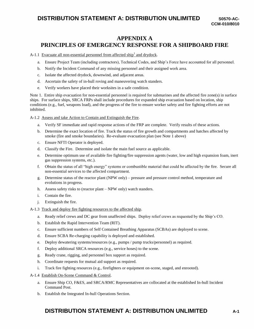
DISTRIBUTION STATEMENT A: DISTRIBUTION UNLIMITED S0570-AC-
CCM-010/8010
DISTRIBUTION STATEMENT A: DISTRIBUTION UNLIMITED A-1
APPENDIX A PRINCIPLES OF EMERGENCY RESPONSE FOR A SHIPBOARD FIRE
A-1.1 Evacuate all non-essential personnel from affected ship1 and drydock.
a. Ensure Project Team (including contractors), Technical Codes, and Ship’s Force have accounted for all personnel.
b. Notify the Incident Command of any missing personnel and their assigned work area.
c. Isolate the affected drydock, downwind, and adjacent areas.
d. Ascertain the safety of in-hull roving and maneuvering watch standers.
e. Verify workers have placed their worksites in a safe condition.
Note 1. Entire ship evacuation for non-essential personnel is required for submarines and the affected fire zone(s) in surface
ships. For surface ships, SRCA FRPs shall include procedures for expanded ship evacuation based on location, ship
conditions (e.g., fuel, weapons load), and the progress of the fire to ensure worker safety and fire fighting efforts are not
inhibited.
A-1.2 Assess and take Action to Contain and Extinguish the Fire.
a. Verify SF immediate and rapid response actions of the FRP are complete. Verify results of these actions.
b. Determine the exact location of fire. Track the status of fire growth and compartments and hatches affected by
smoke (fire and smoke boundaries). Re-evaluate evacuation plan (see Note 1 above)
c. Ensure NFTI Operator is deployed.
d. Classify the Fire. Determine and isolate the main fuel source as applicable.
e. Determine optimum use of available fire fighting/fire suppression agents (water, low and high expansion foam, inert
gas suppression systems, etc.).
f. Obtain the status of all “high energy” systems or combustible material that could be affected by the fire. Secure all
non-essential services to the affected compartment.
g. Determine status of the reactor plant (NPW only) – pressure and pressure control method, temperature and
evolutions in progress.
h. Assess safety risks to (reactor plant – NPW only) watch standers.
i. Contain the fire.
j. Extinguish the fire.
A-1.3 Track and deploy fire fighting resources to the affected ship.
a. Ready relief crews and DC gear from unaffected ships. Deploy relief crews as requested by the Ship’s CO.
b. Establish the Rapid Intervention Team (RIT).
c. Ensure sufficient numbers of Self Contained Breathing Apparatus (SCBAs) are deployed to scene.
d. Ensure SCBA Re-charging capability is deployed and established.
e. Deploy dewatering systems/resources (e.g., pumps / pump trucks/personnel) as required.
f. Deploy additional SRCA resources (e.g., service hoses) to the scene.
g. Ready crane, rigging, and personnel box support as required.
h. Coordinate requests for mutual aid support as required.
i. Track fire fighting resources (e.g., firefighters or equipment on-scene, staged, and enrooted).
A-1.4 Establish On-Scene Command & Control.
a. Ensure Ship CO, F&ES, and SRCA/RMC Representatives are collocated at the established In-hull Incident
Command Post.
b. Establish the Integrated In-hull Operations Section.
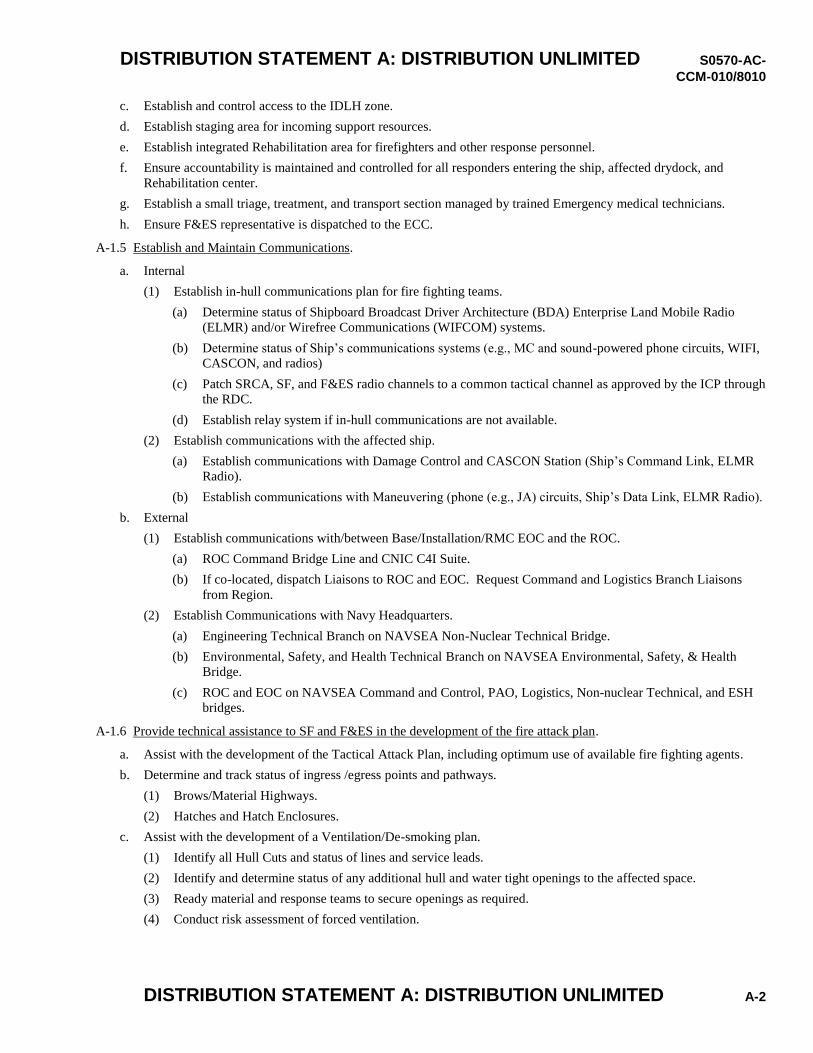
DISTRIBUTION STATEMENT A: DISTRIBUTION UNLIMITED S0570-AC-
CCM-010/8010
DISTRIBUTION STATEMENT A: DISTRIBUTION UNLIMITED A-2
c. Establish and control access to the IDLH zone.
d. Establish staging area for incoming support resources.
e. Establish integrated Rehabilitation area for firefighters and other response personnel.
f. Ensure accountability is maintained and controlled for all responders entering the ship, affected drydock, and
Rehabilitation center.
g. Establish a small triage, treatment, and transport section managed by trained Emergency medical technicians.
h. Ensure F&ES representative is dispatched to the ECC.
A-1.5 Establish and Maintain Communications.
a. Internal
(1) Establish in-hull communications plan for fire fighting teams.
(a) Determine status of Shipboard Broadcast Driver Architecture (BDA) Enterprise Land Mobile Radio
(ELMR) and/or Wirefree Communications (WIFCOM) systems.
(b) Determine status of Ship’s communications systems (e.g., MC and sound-powered phone circuits, WIFI,
CASCON, and radios)
(c) Patch SRCA, SF, and F&ES radio channels to a common tactical channel as approved by the ICP through
the RDC.
(d) Establish relay system if in-hull communications are not available.
(2) Establish communications with the affected ship.
(a) Establish communications with Damage Control and CASCON Station (Ship’s Command Link, ELMR
Radio).
(b) Establish communications with Maneuvering (phone (e.g., JA) circuits, Ship’s Data Link, ELMR Radio).
b. External
(1) Establish communications with/between Base/Installation/RMC EOC and the ROC.
(a) ROC Command Bridge Line and CNIC C4I Suite.
(b) If co-located, dispatch Liaisons to ROC and EOC. Request Command and Logistics Branch Liaisons
from Region.
(2) Establish Communications with Navy Headquarters.
(a) Engineering Technical Branch on NAVSEA Non-Nuclear Technical Bridge.
(b) Environmental, Safety, and Health Technical Branch on NAVSEA Environmental, Safety, & Health
Bridge.
(c) ROC and EOC on NAVSEA Command and Control, PAO, Logistics, Non-nuclear Technical, and ESH
bridges.
A-1.6 Provide technical assistance to SF and F&ES in the development of the fire attack plan.
a. Assist with the development of the Tactical Attack Plan, including optimum use of available fire fighting agents.
b. Determine and track status of ingress /egress points and pathways.
(1) Brows/Material Highways.
(2) Hatches and Hatch Enclosures.
c. Assist with the development of a Ventilation/De-smoking plan.
(1) Identify all Hull Cuts and status of lines and service leads.
(2) Identify and determine status of any additional hull and water tight openings to the affected space.
(3) Ready material and response teams to secure openings as required.
(4) Conduct risk assessment of forced ventilation.
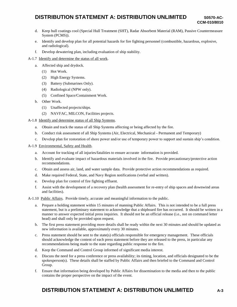
DISTRIBUTION STATEMENT A: DISTRIBUTION UNLIMITED S0570-AC-
CCM-010/8010
DISTRIBUTION STATEMENT A: DISTRIBUTION UNLIMITED A-3
d. Keep hull coatings cool (Special Hull Treatment (SHT), Radar Absorbent Material (RAM), Passive Countermeasure
System (PCMS)).
e. Identify and develop plan for all potential hazards for fire fighting personnel (combustible, hazardous, explosive,
and radiological).
f. Develop dewatering plan, including evaluation of ship stability.
A-1.7 Identify and determine the status of all work.
a. Affected ship and drydock.
(1) Hot Work.
(2) High Energy Systems.
(3) Battery (Submarines Only).
(4) Radiological (NPW only).
(5) Confined Space/Containment Work.
b. Other Work.
(1) Unaffected projects/ships.
(2) NAVFAC, MILCON, Facilities projects.
A-1.8 Identify and determine status of all Ship Systems.
a. Obtain and track the status of all Ship Systems affecting or being affected by the fire.
b. Conduct risk assessment of all Ship Systems (Air, Electrical, Mechanical - Permanent and Temporary)
c. Develop plan for restoration of shore power and/or use of temporary power to support and sustain ship’s condition.
A-1.9 Environmental, Safety and Health.
a. Account for tracking of all injuries/fatalities to ensure accurate information is provided.
b. Identify and evaluate impact of hazardous materials involved in the fire. Provide precautionary/protective action
recommendations.
c. Obtain and assess air, land, and water sample data. Provide protective action recommendations as required.
d. Make required Federal, State, and Navy Region notifications (verbal and written).
e. Develop plan for control of fire fighting effluent.
f. Assist with the development of a recovery plan (health assessment for re-entry of ship spaces and downwind areas
and facilities).
A-1.10 Public Affairs. Provide timely, accurate and meaningful information to the public.
a. Prepare a holding statement within 15 minutes of manning Public Affairs. This is not intended to be a full press
statement, but is a preliminary statement to acknowledge that a shipboard fire has occurred. It should be written in a
manner to answer expected initial press inquiries. It should not be an official release (i.e., not on command letter
head) and shall only be provided upon request.
b. The first press statement providing more details shall be ready within the next 30 minutes and should be updated as
new information is available, approximately every 30 minutes.
c. Press statement should be sent to the state(s) officials responsible for emergency management. These officials
should acknowledge the content of each press statement before they are released to the press, in particular any
recommendations being made to the state regarding public response to the fire.
d. Keep the Command and Control Group informed of significant media interest.
e. Discuss the need for a press conference or press availability; its timing, location, and officials designated to be the
spokesperson(s). These details shall be staffed by Public Affairs and then briefed to the Command and Control
Group.
f. Ensure that information being developed by Public Affairs for dissemination to the media and then to the public
contains the proper perspective on the impact of the event.
DISTRIBUTION STATEMENT A: DISTRIBUTION UNLIMITED S0570-AC-
CCM-010/8010
DISTRIBUTION STATEMENT A: DISTRIBUTION UNLIMITED A-4
g. Develop statements periodically to be used to provide information to the SRCA work force. A statement shall be
prepared near the end of each work shift to provide the latest information as the workers depart.
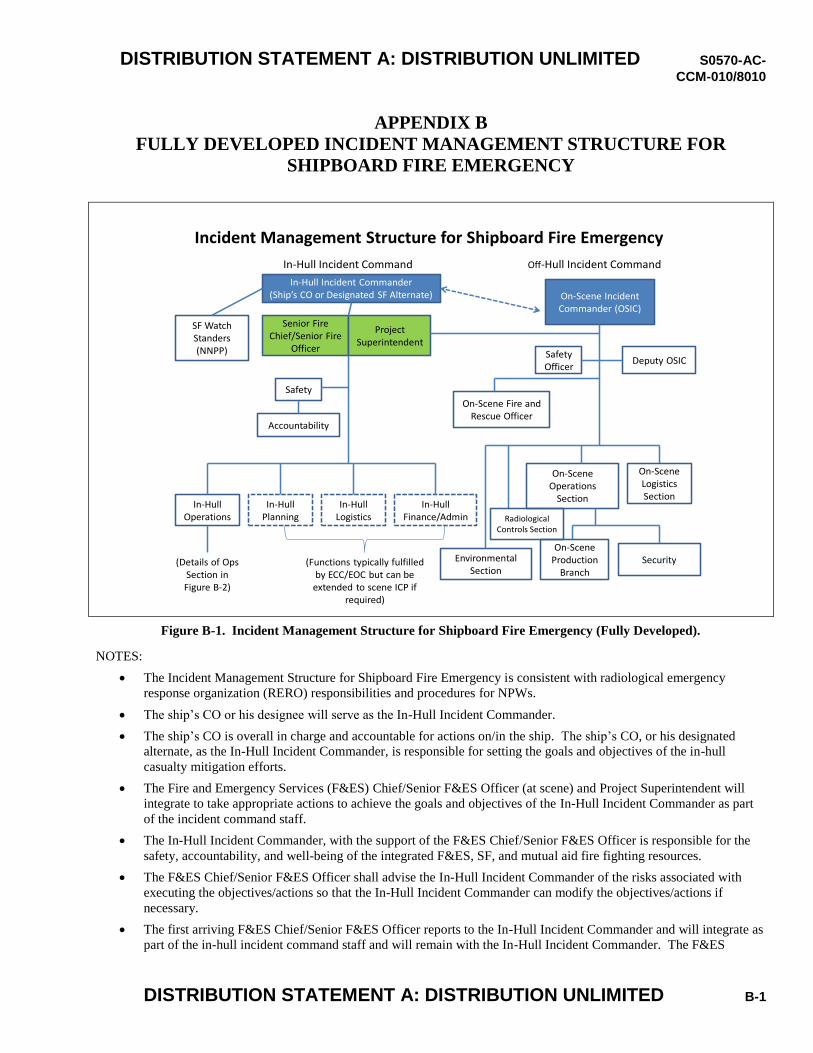
DISTRIBUTION STATEMENT A: DISTRIBUTION UNLIMITED S0570-AC-
CCM-010/8010
DISTRIBUTION STATEMENT A: DISTRIBUTION UNLIMITED B-1
APPENDIX B FULLY DEVELOPED INCIDENT MANAGEMENT STRUCTURE FOR
SHIPBOARD FIRE EMERGENCY
Incident Management Structure for Shipboard Fire Emergency
In-Hull Incident Commander(Ship’s CO or Designated SF Alternate)
Senior Fire Chief/Senior Fire
Officer
Project Superintendent
In-Hull Incident Command Off-Hull Incident Command
Safety
Accountability
In-HullOperations
In-HullPlanning
In-HullLogistics
In-HullFinance/Admin
(Details of Ops Section in Figure B-2)
(Functions typically fulfilled by ECC/EOC but can be
extended to scene ICP if required)
SF Watch Standers(NNPP)
On-Scene Incident Commander (OSIC)
Safety Officer
Deputy OSIC
Environmental Section
On-SceneOperations
Section
On-SceneLogisticsSection
Security
On-Scene Fire and Rescue Officer
On-Scene Production
Branch
Radiological Controls Section
Figure B-1. Incident Management Structure for Shipboard Fire Emergency (Fully Developed).
NOTES:
The Incident Management Structure for Shipboard Fire Emergency is consistent with radiological emergency
response organization (RERO) responsibilities and procedures for NPWs.
The ship’s CO or his designee will serve as the In-Hull Incident Commander.
The ship’s CO is overall in charge and accountable for actions on/in the ship. The ship’s CO, or his designated
alternate, as the In-Hull Incident Commander, is responsible for setting the goals and objectives of the in-hull
casualty mitigation efforts.
The Fire and Emergency Services (F&ES) Chief/Senior F&ES Officer (at scene) and Project Superintendent will
integrate to take appropriate actions to achieve the goals and objectives of the In-Hull Incident Commander as part
of the incident command staff.
The In-Hull Incident Commander, with the support of the F&ES Chief/Senior F&ES Officer is responsible for the
safety, accountability, and well-being of the integrated F&ES, SF, and mutual aid fire fighting resources.
The F&ES Chief/Senior F&ES Officer shall advise the In-Hull Incident Commander of the risks associated with
executing the objectives/actions so that the In-Hull Incident Commander can modify the objectives/actions if
necessary.
The first arriving F&ES Chief/Senior F&ES Officer reports to the In-Hull Incident Commander and will integrate as
part of the in-hull incident command staff and will remain with the In-Hull Incident Commander. The F&ES
DISTRIBUTION STATEMENT A: DISTRIBUTION UNLIMITED S0570-AC-
CCM-010/8010
DISTRIBUTION STATEMENT A: DISTRIBUTION UNLIMITED B-2
Officer will offer F&ES resources and capabilities to help combat the casualty. Once the ship accepts assistance
from F&ES with combating the casualty, the next F&ES Chief/Senior F&ES Officer will serve as the In-Hull
Operations Section Chief or assist the In-Hull Operations Section Chief as one of the Tactical Advisors (see notes
regarding In-Hull Operations Section Chief). Based on the priority dictated by the casualty situation, additional
roles for senior F&ES officers, such as the On-Scene Fire and Rescue Officer and elevation of the In-Hull Safety
Officer to a senior F&ES officer, need to be filled as additional senior F&ES officers arrive. Fire Response Plans
(FRPs) and standard operating procedures should include a means to assemble the necessary number of senior
F&ES officers to staff the above roles.
The On-Scene Fire and Rescue Officer will be responsible for coordinating RERO requested fire fighting actions as
directed by OSIC and will be responsible for ensuring medical attention is provided to off-hull responders.
The on-duty Senior Security Officer will initially report to the in-hull ICP in order to assist the CO and senior F&ES
officer with the determination and implementation of in-hull and immediate scene related security objectives, until
such time the OSIC ICP has been already established. When the OSIC ICP has been established, the senior security
officer will report to the on-scene operations section to assist with the determination and implementation of security
objectives.
Upon arrival of the Shipyard OSIC, the OSIC shall report to the In-hull ICP to receive an in-brief from the In-Hull
Incident Commander before assuming duties and establishing the Off-Hull Incident Command Post (ICP). The
OSIC shall coordinate off-hull actions and assist with like functions that fall under the In-Hull Operations Section
through the Project Superintendent.
“In-Hull” is a generic term referring to actions that take place in, on, or immediately adjacent to the ship where the
incident is occurring.
“On-scene” and “Off-Hull” in the context of this construct refers to the portion of the command structure and
associated activities that occur off of and NOT immediately adjacent to the hull where the incident is occurring.
The ship’s CO is the supported commander and the SY OSIC is the supporting commander for the fire as depicted
by the dashed line in Figure B-1.
NOTE: Coordination of the EOC and ECC roles, responsibilities, and actions shall be addressed by the FRP.
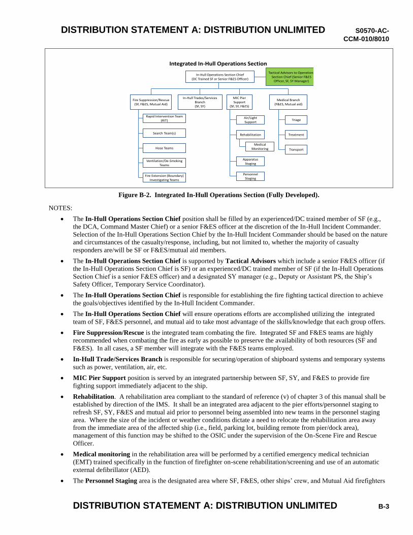
DISTRIBUTION STATEMENT A: DISTRIBUTION UNLIMITED S0570-AC-
CCM-010/8010
DISTRIBUTION STATEMENT A: DISTRIBUTION UNLIMITED B-3
Integrated In-Hull Operations Section
Fire Suppression/Rescue(SF, F&ES, Mutual Aid)
In-Hull Operations Section Chief(DC Trained SF or Senior F&ES Officer)
In-Hull Trades/Services Branch(SF, SY)
Medical Branch(F&ES, Mutual aid)
MIC Pier Support
(SF, SY, F&ES)
Apparatus Staging
Rehabilitation
Air/Light Support
Medical Monitoring
Personnel Staging
Triage
Transport
Treatment
Rapid Intervention Team(RIT)
Hose Teams
Search Team(s)
Ventilation/De-Smoking Teams
Fire Extension (Boundary) Investigating Teams
Tactical Advisors to Operations Section Chief (Senior F&ES
Officer, SF, SY Manager)
Figure B-2. Integrated In-Hull Operations Section (Fully Developed).
NOTES:
The In-Hull Operations Section Chief position shall be filled by an experienced/DC trained member of SF (e.g.,
the DCA, Command Master Chief) or a senior F&ES officer at the discretion of the In-Hull Incident Commander.
Selection of the In-Hull Operations Section Chief by the In-Hull Incident Commander should be based on the nature
and circumstances of the casualty/response, including, but not limited to, whether the majority of casualty
responders are/will be SF or F&ES/mutual aid members.
The In-Hull Operations Section Chief is supported by Tactical Advisors which include a senior F&ES officer (if
the In-Hull Operations Section Chief is SF) or an experienced/DC trained member of SF (if the In-Hull Operations
Section Chief is a senior F&ES officer) and a designated SY manager (e.g., Deputy or Assistant PS, the Ship’s
Safety Officer, Temporary Service Coordinator).
The In-Hull Operations Section Chief is responsible for establishing the fire fighting tactical direction to achieve
the goals/objectives identified by the In-Hull Incident Commander.
The In-Hull Operations Section Chief will ensure operations efforts are accomplished utilizing the integrated
team of SF, F&ES personnel, and mutual aid to take most advantage of the skills/knowledge that each group offers.
Fire Suppression/Rescue is the integrated team combating the fire. Integrated SF and F&ES teams are highly
recommended when combating the fire as early as possible to preserve the availability of both resources (SF and
F&ES). In all cases, a SF member will integrate with the F&ES teams employed.
In-Hull Trade/Services Branch is responsible for securing/operation of shipboard systems and temporary systems
such as power, ventilation, air, etc.
MIC Pier Support position is served by an integrated partnership between SF, SY, and F&ES to provide fire
fighting support immediately adjacent to the ship.
Rehabilitation. A rehabilitation area compliant to the standard of reference (v) of chapter 3 of this manual shall be
established by direction of the IMS. It shall be an integrated area adjacent to the pier efforts/personnel staging to
refresh SF, SY, F&ES and mutual aid prior to personnel being assembled into new teams in the personnel staging
area. Where the size of the incident or weather conditions dictate a need to relocate the rehabilitation area away
from the immediate area of the affected ship (i.e., field, parking lot, building remote from pier/dock area),
management of this function may be shifted to the OSIC under the supervision of the On-Scene Fire and Rescue
Officer.
Medical monitoring in the rehabilitation area will be performed by a certified emergency medical technician
(EMT) trained specifically in the function of firefighter on-scene rehabilitation/screening and use of an automatic
external defibrillator (AED).
The Personnel Staging area is the designated area where SF, F&ES, other ships’ crew, and Mutual Aid firefighters
DISTRIBUTION STATEMENT A: DISTRIBUTION UNLIMITED S0570-AC-
CCM-010/8010
DISTRIBUTION STATEMENT A: DISTRIBUTION UNLIMITED B-4
ready for deployment are in-briefed, staged, and assembled into teams. Personnel that successfully complete
rehabilitation will report to the personnel staging area and become part of the resources available for deployment.
The Apparatus Staging area that is within “Operations” houses apparatus resources that have been provided to the
in-hull organization for near term deployment. For large incidents involving great amounts of external apparatus, it
is recommended that the OSIC “Logistics” section establish a remote staging area where assets can be staged and
called as necessary by “Operations”.
Medical Branch is an F&ES function, with possible support by trained SF, responsible to triage, treat and transport
injured personnel.
The Branch/Group “blocks” depicted above are event driven. Some of the blocks may not be necessary for
particular event types while other unique events may dictate the need to establish additional
branches/groups/divisions.
DISTRIBUTION STATEMENT A: DISTRIBUTION UNLIMITED S0570-AC-
CCM-010/8010
DISTRIBUTION STATEMENT A: DISTRIBUTION UNLIMITED C-1
APPENDIX C ENGINEERED FIRE RESPONSE STRATEGY
In coordination among NAVSEA fire fighting working groups, numerous fire fighting and fire safety capability changes have
been made and incorporated as FRP requirements in this manual. Improvements include shipyard firefighter manning
increases, increase to and standardization of fire fighting and support equipment, enhanced training, installation of fire
detection sensors, and needed procedural improvements. These changes intuitively are expected to prevent fires and if they
occur, mitigate the risk of damage to the ship.
A preliminary standard set of response capabilities to include fire fighting personnel, equipment and expected response times
have been determined. These have been exercised and validated during extended submarine exercises. Collectively, these
are the Engineered Fire Response Strategy (EFRS) attributes. It is expected the times listed will be different based on
numerous variables. Each SRCA shall evaluate their specific circumstances and establish times and response capabilities to
complete Table C-1 and incorporate the completed Table into the FRP.
A more rigorous analysis to evaluate the enhanced FRPs to ensure they have sufficient capability to control and extinguish a
shipboard fire in time to prevent significant damage is in progress. This analysis is applying engineering principles to
evaluate the fire fighting capability attributes based on current knowledge and supplemented by modeling and future lessons
learned. The result will be a modification to existing requirements and SRCA FRPs to match capability to requirements.
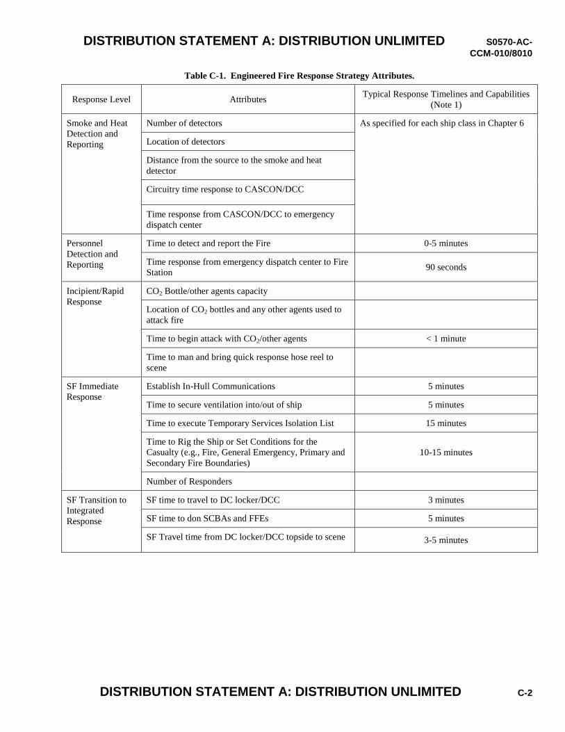
DISTRIBUTION STATEMENT A: DISTRIBUTION UNLIMITED S0570-AC-
CCM-010/8010
DISTRIBUTION STATEMENT A: DISTRIBUTION UNLIMITED C-2
Table C-1. Engineered Fire Response Strategy Attributes.
Response Level Attributes Typical Response Timelines and Capabilities
(Note 1)
Smoke and Heat
Detection and
Reporting
Number of detectors As specified for each ship class in Chapter 6
Location of detectors
Distance from the source to the smoke and heat
detector
Circuitry time response to CASCON/DCC
Time response from CASCON/DCC to emergency
dispatch center
Personnel
Detection and
Reporting
Time to detect and report the Fire 0-5 minutes
Time response from emergency dispatch center to Fire
Station 90 seconds
Incipient/Rapid
Response
CO2 Bottle/other agents capacity
Location of CO2 bottles and any other agents used to
attack fire
Time to begin attack with CO2/other agents < 1 minute
Time to man and bring quick response hose reel to
scene
SF Immediate
Response
Establish In-Hull Communications 5 minutes
Time to secure ventilation into/out of ship 5 minutes
Time to execute Temporary Services Isolation List 15 minutes
Time to Rig the Ship or Set Conditions for the
Casualty (e.g., Fire, General Emergency, Primary and
Secondary Fire Boundaries)
10-15 minutes
Number of Responders
SF Transition to
Integrated
Response
SF time to travel to DC locker/DCC 3 minutes
SF time to don SCBAs and FFEs 5 minutes
SF Travel time from DC locker/DCC topside to scene 3-5 minutes
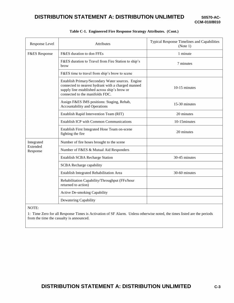
DISTRIBUTION STATEMENT A: DISTRIBUTION UNLIMITED S0570-AC-
CCM-010/8010
DISTRIBUTION STATEMENT A: DISTRIBUTION UNLIMITED C-3
Table C-1. Engineered Fire Response Strategy Attributes. (Cont.)
Response Level Attributes Typical Response Timelines and Capabilities
(Note 1)
F&ES Response F&ES duration to don FFEs 1 minute
F&ES duration to Travel from Fire Station to ship’s
brow 7 minutes
F&ES time to travel from ship’s brow to scene
Establish Primary/Secondary Water sources. Engine
connected to nearest hydrant with a charged manned
supply line established across ship’s brow or
connected to the manifolds FDC.
10-15 minutes
Assign F&ES IMS positions: Staging, Rehab,
Accountability and Operations 15-30 minutes
Establish Rapid Intervention Team (RIT) 20 minutes
Establish ICP with Common Communications 10-15minutes
Establish First Integrated Hose Team on-scene
fighting the fire 20 minutes
Integrated
Extended
Response
Number of fire hoses brought to the scene
Number of F&ES & Mutual Aid Responders
Establish SCBA Recharge Station 30-45 minutes
SCBA Recharge capability
Establish Integrated Rehabilitation Area 30-60 minutes
Rehabilitation Capability/Throughput (FFs/hour
returned to action)
Active De-smoking Capability
Dewatering Capability
NOTE:
1: Time Zero for all Response Times is Activation of SF Alarm. Unless otherwise noted, the times listed are the periods
from the time the casualty is announced.

DISTRIBUTION STATEMENT A: DISTRIBUTION UNLIMITED S0570-AC-
CCM-010/8010
DISTRIBUTION STATEMENT A: DISTRIBUTION UNLIMITED C-4
THIS PAGE INTENTIONALLY LEFT BLANK.
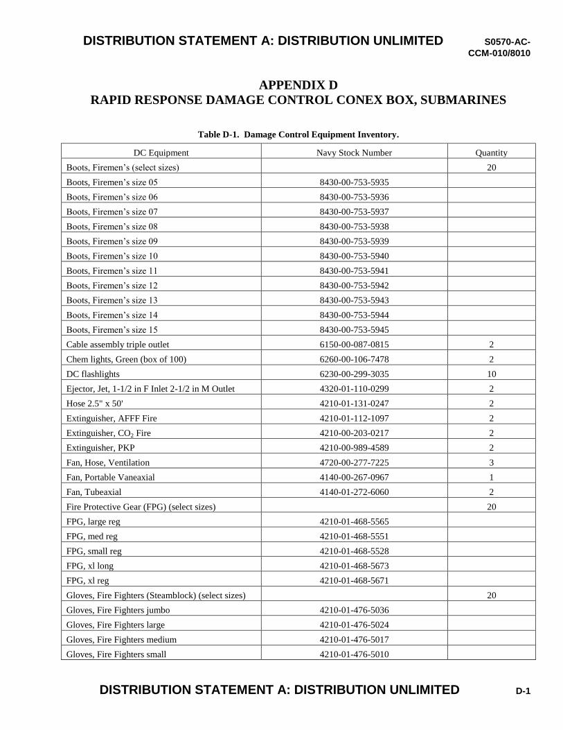
DISTRIBUTION STATEMENT A: DISTRIBUTION UNLIMITED S0570-AC-
CCM-010/8010
DISTRIBUTION STATEMENT A: DISTRIBUTION UNLIMITED D-1
APPENDIX D RAPID RESPONSE DAMAGE CONTROL CONEX BOX, SUBMARINES
Table D-1. Damage Control Equipment Inventory.
DC Equipment Navy Stock Number Quantity
Boots, Firemen’s (select sizes) 20
Boots, Firemen’s size 05 8430-00-753-5935
Boots, Firemen’s size 06 8430-00-753-5936
Boots, Firemen’s size 07 8430-00-753-5937
Boots, Firemen’s size 08 8430-00-753-5938
Boots, Firemen’s size 09 8430-00-753-5939
Boots, Firemen’s size 10 8430-00-753-5940
Boots, Firemen’s size 11 8430-00-753-5941
Boots, Firemen’s size 12 8430-00-753-5942
Boots, Firemen’s size 13 8430-00-753-5943
Boots, Firemen’s size 14 8430-00-753-5944
Boots, Firemen’s size 15 8430-00-753-5945
Cable assembly triple outlet 6150-00-087-0815 2
Chem lights, Green (box of 100) 6260-00-106-7478 2
DC flashlights 6230-00-299-3035 10
Ejector, Jet, 1-1/2 in F Inlet 2-1/2 in M Outlet 4320-01-110-0299 2
Hose 2.5" x 50' 4210-01-131-0247 2
Extinguisher, AFFF Fire 4210-01-112-1097 2
Extinguisher, CO2 Fire 4210-00-203-0217 2
Extinguisher, PKP 4210-00-989-4589 2
Fan, Hose, Ventilation 4720-00-277-7225 3
Fan, Portable Vaneaxial 4140-00-267-0967 1
Fan, Tubeaxial 4140-01-272-6060 2
Fire Protective Gear (FPG) (select sizes) 20
FPG, large reg 4210-01-468-5565
FPG, med reg 4210-01-468-5551
FPG, small reg 4210-01-468-5528
FPG, xl long 4210-01-468-5673
FPG, xl reg 4210-01-468-5671
Gloves, Fire Fighters (Steamblock) (select sizes) 20
Gloves, Fire Fighters jumbo 4210-01-476-5036
Gloves, Fire Fighters large 4210-01-476-5024
Gloves, Fire Fighters medium 4210-01-476-5017
Gloves, Fire Fighters small 4210-01-476-5010
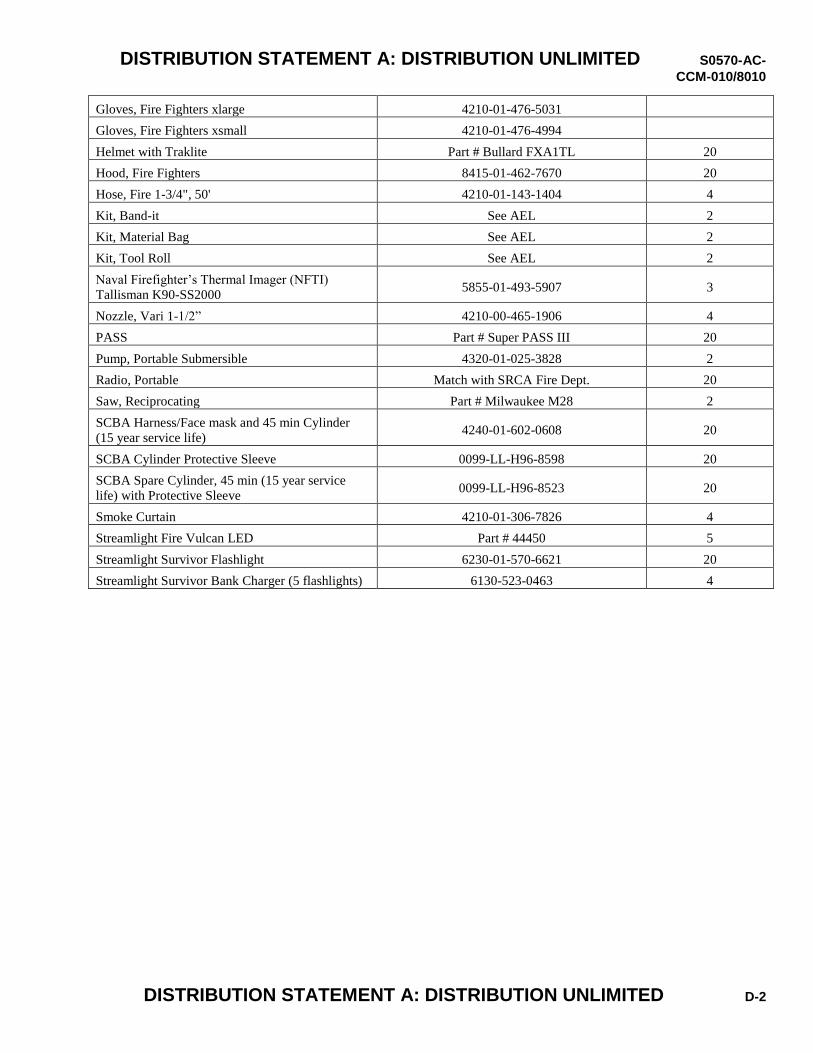
DISTRIBUTION STATEMENT A: DISTRIBUTION UNLIMITED S0570-AC-
CCM-010/8010
DISTRIBUTION STATEMENT A: DISTRIBUTION UNLIMITED D-2
Gloves, Fire Fighters xlarge 4210-01-476-5031
Gloves, Fire Fighters xsmall 4210-01-476-4994
Helmet with Traklite Part # Bullard FXA1TL 20
Hood, Fire Fighters 8415-01-462-7670 20
Hose, Fire 1-3/4", 50' 4210-01-143-1404 4
Kit, Band-it See AEL 2
Kit, Material Bag See AEL 2
Kit, Tool Roll See AEL 2
Naval Firefighter’s Thermal Imager (NFTI)
Tallisman K90-SS2000 5855-01-493-5907 3
Nozzle, Vari 1-1/2” 4210-00-465-1906 4
PASS Part # Super PASS III 20
Pump, Portable Submersible 4320-01-025-3828 2
Radio, Portable Match with SRCA Fire Dept. 20
Saw, Reciprocating Part # Milwaukee M28 2
SCBA Harness/Face mask and 45 min Cylinder
(15 year service life) 4240-01-602-0608 20
SCBA Cylinder Protective Sleeve 0099-LL-H96-8598 20
SCBA Spare Cylinder, 45 min (15 year service
life) with Protective Sleeve 0099-LL-H96-8523 20
Smoke Curtain 4210-01-306-7826 4
Streamlight Fire Vulcan LED Part # 44450 5
Streamlight Survivor Flashlight 6230-01-570-6621 20
Streamlight Survivor Bank Charger (5 flashlights) 6130-523-0463 4
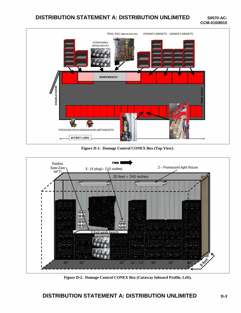
DISTRIBUTION STATEMENT A: DISTRIBUTION UNLIMITED S0570-AC-
CCM-010/8010
DISTRIBUTION STATEMENT A: DISTRIBUTION UNLIMITED D-3
Figure D-1. Damage Control CONEX Box (Top View).
Figure D-2. Damage Control CONEX Box (Cutaway Inboard Profile, Left).
VIDMAR CABINETS VIDMAR CABINETS
8 F
EE
T W
IDE
20 FEET LONG
TRAC-PAC (above bench)
FFE/SCBA-PACKS/MASKS/HELMETS/BOOTS
DO
UB
LE
DO
OR
SCBA bottles
(below bench)
WORKBENCH
20 feet = 240 inches
30” 30” 30” 22 – 1/2” 30” 30”
FWD
3 - (4 plug) – 110 outlets 2 – Florescent light fixture Radios
Saw - Zaw NFTI
30”
3 foot work bench
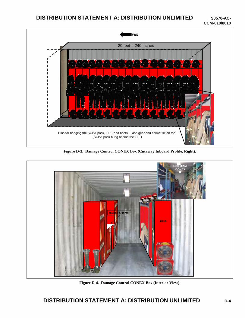
DISTRIBUTION STATEMENT A: DISTRIBUTION UNLIMITED S0570-AC-
CCM-010/8010
DISTRIBUTION STATEMENT A: DISTRIBUTION UNLIMITED D-4
Figure D-3. Damage Control CONEX Box (Cutaway Inboard Profile, Right).
Figure D-4. Damage Control CONEX Box (Interior View).
BINS
USS MIAMI
CONEX
Radios & lights
VIDMAR
CABINETS
FWD
20 feet = 240 inches
Bins for hanging the SCBA pack, FFE, and boots. Flash gear and helmet sit on top. (SCBA pack hung behind the FFE)
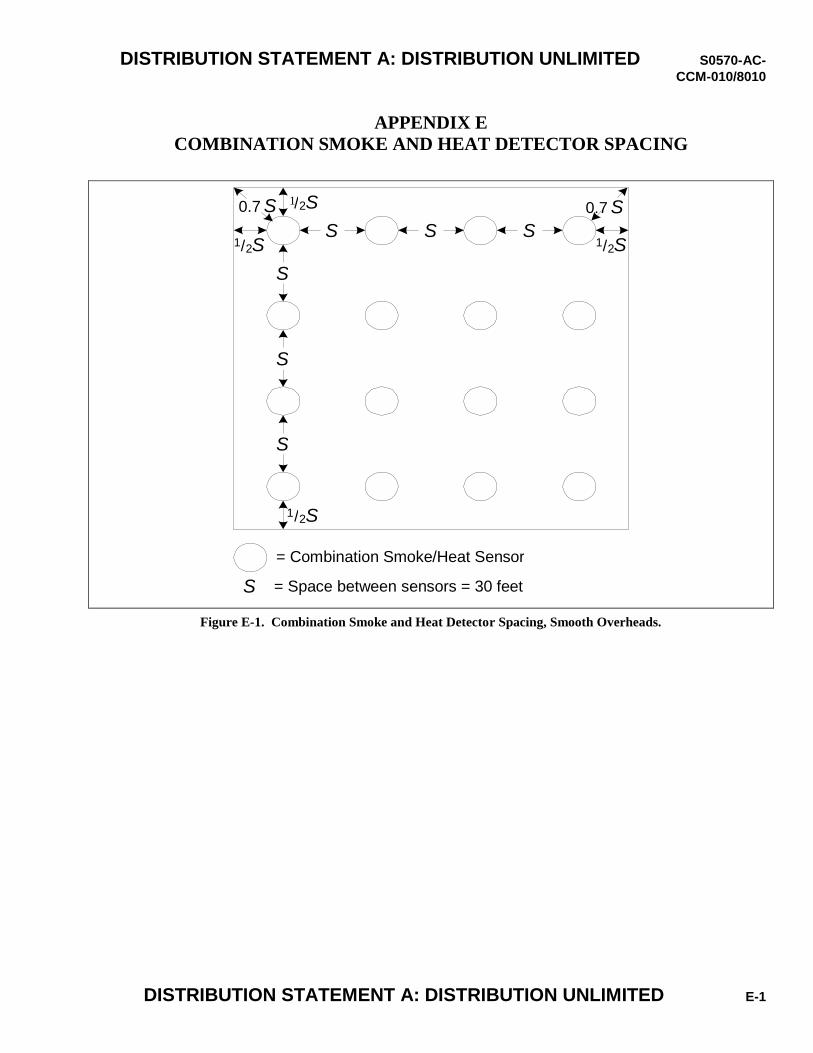
DISTRIBUTION STATEMENT A: DISTRIBUTION UNLIMITED S0570-AC-
CCM-010/8010
DISTRIBUTION STATEMENT A: DISTRIBUTION UNLIMITED E-1
APPENDIX E COMBINATION SMOKE AND HEAT DETECTOR SPACING
Figure E-1. Combination Smoke and Heat Detector Spacing, Smooth Overheads.
S S S
S
S
S
1 / 2 S
/ 2 S
1 / 2 S
1 / 2 S
0.7 S 0.7 S
= Combination Smoke/Heat Sensor
S = Space between sensors = 30 feet
1
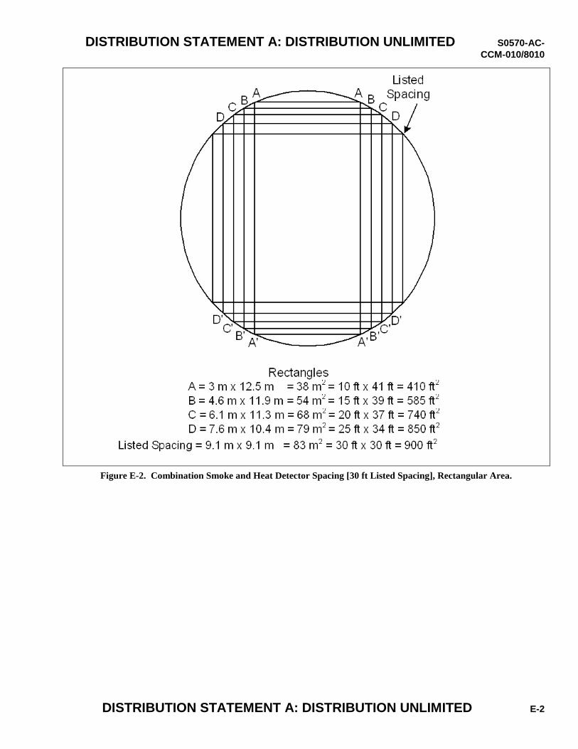
DISTRIBUTION STATEMENT A: DISTRIBUTION UNLIMITED S0570-AC-
CCM-010/8010
DISTRIBUTION STATEMENT A: DISTRIBUTION UNLIMITED E-2
Figure E-2. Combination Smoke and Heat Detector Spacing [30 ft Listed Spacing], Rectangular Area.
DISTRIBUTION STATEMENT A: DISTRIBUTION UNLIMITED S0570-AC-
CCM-010/8010
DISTRIBUTION STATEMENT A: DISTRIBUTION UNLIMITED F-1
APPENDIX F DRILL GUIDE AND AUTHORIZATION FORMS
1. Drill Guides will contain the following sections:
a. Title: Brief description of the drill.
b. General Description: This should be a short paragraph amplifying the drill title.
c. Duration: Estimated time from drill initiation to completion.
d. Initial Conditions: Ship conditions (e.g., waterborne, in dock, electric plant configuration, watch condition, etc.)
required before the drill can be initiated.
e. Point of Termination: The point of termination occurs when drill training objectives are met.
f. Final Conditions: Any conditions that restrict ship’s operations that may be present at the end of the drill. The guide
shall ensure that the effects of alternate courses of action are considered.
g. Method of Initiation: Specific initiation and simulation direction to the drill team.
h. A list of post-initiation anomalies, using the special scenarios in references (b) and (c) of chapter 12 of this manual.
i. Expected Actions: Summary of significant actions expected from the emergency response team. This section shall
include:
(1) Alternate courses of action. The drill or evolution team must understand allowable, safe alternate courses of
action and be prepared to evaluate and safely control them based on the team’s response to the casualty, as
determined by Subject Matter Experts (SME) on the drill team. This section shall include the technical data
that addresses the progress of the casualty and its effect on the ship and ship’s systems (temporary and
permanent) conditions.
(2) Timing. The drill team should understand timing of events and simulations. A drill timeline that includes a
time-based description of the spread of the fire that will depend on the timeliness of response actions is a
useful tool for drill control and evaluation and shall be included. For example, fires in wireways may spread to
the next compartment unless a fire hose is brought to bear within 5 minutes by SF.
(3) Precautions. The drill team, as defined in paragraph 1.j below, must understand precautions necessary to
prevent injury or damage to equipment.
(4) Safety intervention points. Safety intervention points are specific conditions that require action to prevent
personnel injury or equipment damage.
NOTE: Safety intervention points are assigned to safety observers who have no simulation or monitor duties.
j. Required Personnel: The drill guide shall include a list of personnel required to perform desired simulation
(designated simulators), personnel required to adequately monitor the event (designated monitors), and personnel
necessary to safely conduct the event (designated safety observers). This list shall include assigned tasks and
locations. Simulators, monitors, and safety observers comprise the drill team.
k. Performance criteria. The guide shall include a section to document the time of significant key events and include
criteria for satisfactory performance in meeting these times in compliance with established fire response standards.
These will include at a minimum:
(1) Immediately and accurately reporting the fire, to the CASCON/Quarterdeck and F&ES, from inception.
(2) Immediate response by onboard ship’s watch-standers, response by SF Rapid Response Team/DC repair
lockers personnel, and F&ES arrival at the ship.
(3) F&ES in-hull fighting the fire.
(4) Ambulance arrival or own ship medical staff response.
(5) The effective transition of fire fighting from SF only to integrated fire attack teams (SF, other ship crews, and
F&ES responders).
(6) Effectiveness of evacuation and muster of SRCA, AIT, and other non-SF personnel.
DISTRIBUTION STATEMENT A: DISTRIBUTION UNLIMITED S0570-AC-
CCM-010/8010
DISTRIBUTION STATEMENT A: DISTRIBUTION UNLIMITED F-2
2. Drill Authorization Forms (DAF) will be used to approve the conduct of an individual drill and are based on the
applicable, approved drill guide. The authorization form will contain the following information:
a. Purpose: Specifies the training objective of the drill. This section shall not merely reiterate the title of the drill, as
the same drill guide can be used for very different purposes. For example, a fire drill run using a specific drill guide
can be executed primarily to practice immediate response or to fully assess comprehensive fire fighting practices.
b. Point of Termination: Point at which this particular drill will be stopped. This point should be no later than the
termination point specified on the drill guide and will depend on the training objective of the drill.
c. Drill Guide Modifications: This section shall be used to identify minor modifications to the drill guide, if applicable
along with identifying specific details of the drill taken from the guide. For example, the guide shall list a set of
standard anomalies that can be inserted and this (or a separate) section of the DAF can be used to identify the
anomalies that will be exercised for the particular drill. It also should be used to select the specific method of
initiation. For example the drill guide can be prepared for a Class A fire in a particular space with multiple means to
initiate/sources. The DAF shall be used to provide this specific information.
d. Personnel Assignments: A specific list of simulators, monitors, and safety observers, by name. Safety observers
must be qualified on the watch station or assignment they are observing.
e. Significant or Recurring Deficiencies: List of deficiencies the drill team should look for. These deficiencies can be
derived from a variety of sources, including recent ship/SRCA events, lessons learned, etc.
DISTRIBUTION STATEMENT A: DISTRIBUTION UNLIMITED S0570-AC-
CCM-010/8010
DISTRIBUTION STATEMENT A: DISTRIBUTION UNLIMITED G-1
APPENDIX G GLOSSARY
ALARM SYSTEM: Generic term for any initiating device and/or notification appliances. In some cases, a single locally
produced component can serve as both an initiating device and notification appliance.
ALTERATION INSTALLATION TEAM (AIT): A unit (military, civilian, or contractor) under the direction of the AIT
Manager, or designated agent of the AIT Manager, that is trained and equipped to accomplish specific alterations on specific
ships.
AVAILABILITY: Any maintenance, modernization period where industrial work is performed/managed by an LMA.
AVAILABILITY WORK PACKAGE (AWP) : Describes/lists authorized industrial work and associated Forces Afloat work
for modernization, maintenance, and repair during the availability.
CASUALTY CONTROL (CASCON) SYSTEM: The shipboard system that replaces the ship’s permanent casualty
reporting, announcing, and communication system; used to report fires inside the ship to the central location (i.e., the
CASCON Station). [See Chapter 8].
CASUALTY CONTROL (CASCON) STATION: Central location, usually outside the ship near and in sight of the ship, that
has the alarm indication, voice communication, and other tools needed to communicate with a shipboard casualty scene,
make shipboard announcements, and initiate alarms to the emergency dispatch center. [See Chapter 8].
CHIEF OF NAVAL OPERATIONS (CNO) SCHEDULED AVAILABILITY: Maintenance, modernization periods where
industrial work is performed that are scheduled by the CNO. Examples include Regular Overhaul, Complex Overhaul,
Engineered Overhaul, Refueling Overhaul, Refueling Complex Overhaul, Engineered Refueling Overhaul, Depot
Modernization Period, Planned Incremental Availability, Docking Planned Incremental Availability, Selected Restricted
Availability (SRA), Docking SRA, Phased Maintenance Availability, Docking Phased Maintenance Availability, Extended
SRA, Extended Docking SRA, Incremental SRA, Interim Drydock Availability (IDD), Pre-Inactivation Restricted
Availability (PIRA), and Inactivation Availability.
CLASS A FIRE: Class A fires involve wood and wood products, cloth, textiles and fibrous materials, paper and paper
products.
CLASS B FIRE: Class B fires involve flammable and combustible liquids such as gasoline, diesel fuel (F-76), jet
fuels, hydraulic fluid and lube oil. Class B fires also involve flammable gases, such as acetylene.
CLASS C FIRE: Class C fires are energized electrical fires.
CLASS D FIRE: Class D fires involve combustible metals, such as magnesium and titanium.
COMBUSTIBLE: A material that, in the form in which it is used and under the conditions anticipated, will ignite and burn; a
material that does not meet the definition of noncombustible or limited- combustible; or any liquid that has a closed cup flash
point at or above 150 °F, as determined by NFPA Codes and Standards 30, Flammable and Combustible Liquids Code. The
terminology of “flammable” and “combustible” liquid is sometimes used interchangeably due to differing definitions in
industry, regulatory bodies, and the military.
DAMAGE CONTROL CENTRAL (DCC): The central location where reports from shipboard repair parties (fire
responders) are received, the overall condition of the ship is evaluated and corrective actions to be taken are directed in the
most effective manner. Graphic records of the damage are made on various damage control diagrams and status boards as
reports are received. During large availabilities, DCC may be moved off the ship.
EMERGENCY DISPATCH CENTER: The central location in the region (Federal or civil) that receives emergency calls and
dispatches Fire & Emergency Services (F&ES). The emergency dispatch center is equivalent to the Region or Installation
emergency dispatch center, and may also be referred to as the Public Safety Access Point (PSAP).
DISTRIBUTION STATEMENT A: DISTRIBUTION UNLIMITED S0570-AC-
CCM-010/8010
DISTRIBUTION STATEMENT A: DISTRIBUTION UNLIMITED G-2
EMERGENCY OPERATIONS CENTER (EOC): The site from which Navy Installations or civil government officials
(municipal, county, State and Federal) exercise direction and control in an emergency. The Installation EOC is a NIMS-
compliant multi-agency coordination system utilizing the Incident/Unified Command System’s organizational structure to
provide an Installation staff to support execution of the Installation Emergency Management (EM) Plan, Anti-terrorism (AT)
Plan, other supporting plans, Defense Support Civil Authorities (DSCA) missions, the Operational Plans of assigned
Combatant, Component, & Fleet Commanders, and the National Response Plan. The mission of the Installation EOC is to
support the Incident Commander (IC) or Unified Commander (UC) during emergencies with resource management support
and establishing strategic/operational-level objectives, as necessary. The EOC is responsible for coordination and liaison
with Local, Other Service, and/or private response and recovery assets. From the Installation EOC, the Installation
Commanding Officer exercises and executes operational control over all assigned Installation assets and may reallocate those
assets on its own volition to support affected areas during an emergency.
EMERGENCY RESPONSE TEAM (ERT): SRCA, SF and F&ES personnel who respond to major fires and constitute the
incident management structure. [See 3.2.4].
FAST CRUISE: A period immediately prior to underway trials during which Ship’s Force operates the ship for dockside
training. Fast Cruise shall, as far as practical, simulate at-sea operating conditions.
FIRE: State, process, or instance of combustion in which fuel or other material is ignited and combined with oxygen, giving
off light, heat, and flame.
FIRE AND EMERGENCY SERVICES (F&ES): The organization responsible for the primary response to fires. The
civilian (Federal or otherwise) fire department.
FIRE BOUNDARY : A fire boundary is a temporary boundary set during a fire by immediate fire responders or firefighters
by closing doors, hatches and other closures. [See 11.2].
FIRE PROOF: For purposes of this manual, a material that is fire resistant.
FIRE RESISTANT: For purposes of this manual, a material that has been treated with a fire retardant.
FIRE RESPONSE PLAN (FRP): Plan required by Occupational Safety and Health Standards for Shipyard Employment, 29
CFR Part 1915 Subpart P, Fire Protection in Shipyard Employment that establishes in advance the actions to be taken at the
time of a fire. [See 3.2].
FIRE RETARDANT: A liquid, or gas that tends to inhibit combustion when applied on, mixed in, or combined with
combustible materials.
FIRE SAFETY COUNCIL (FSC): Collectively, the persons designated by the SRCA, the Ship CO, the NSA and the NSRO
(as assigned) to approve ship specific configurations relevant to the requirements of this manual. [See paragraph 2.1.1]
FIRE SAFETY OFFICER (FSO): The SRCA representative to the FSC. [See paragraph 2.1.2].
FIRE SAFETY WATCH (FSW): The watch-standers assigned specific fire related watch-standing duties such as patrolling
the ship and manning CASCON/DCC/Quarterdeck. Usually FSWs are SF personnel on ship’s in commission and are SRCA
personnel during new construction pre-commissioning and during inactivation and recycling availabilities after
decommissioning. [See paragraph 2.1.3].
FIRE ZONE BOUNDARY: A fire zone boundary is a permanent, continuous, interior bulkhead or deck system designed to
limit the passage of flame and smoke beyond a fire zone and provides protected staging areas for firefighters.
FLAME RESISTANT: A material meeting the flame propagation criteria of NFPA Codes and Standards 701, Standard
Methods of Fire Tests for Flame Propagation of Textiles and Films.
FLAMMABLE GAS: A material that is a gas at 68 degrees F or less at an absolute pressure of 14.7 psi, that is ignitable at an
absolute pressure of 14.7 psi when in a mixture of 13 percent or less by volume with air, or that has a flammable range at an
absolute pressure of 14.7 psi with air of at least 12 percent, regardless of the lower limit.
DISTRIBUTION STATEMENT A: DISTRIBUTION UNLIMITED S0570-AC-
CCM-010/8010
DISTRIBUTION STATEMENT A: DISTRIBUTION UNLIMITED G-3
FLAMMABLE LIQUID: For purposes of this manual, any liquid with a closed cup flashpoint below 150 degrees F or less.
The terminology of “flammable” and “combustible” liquid is sometimes used interchangeably due to differing definitions in
industry, regulatory bodies, and the military.
HOT WORK: Flame heating, welding, torch cutting, brazing, carbon arc gouging, and other operations that produce heat, by
any means, of 400F (204C), or more. [See 4.1].
IN COMMISSION: Ships normally are placed in commission shortly after delivery.
IN SERVICE: Nuclear powered ships are assigned an active status of In-Service approximately two to four weeks (two to
four months for aircraft carriers) prior to the commencement of Sea Trials and maintain this status until commissioning.
INCIDENT COMMAND SYSTEM (ICS). A standardized incident emergency management construct specifically designed
to provide for the adoption of an integrated organizational structure that reflects the complexity and demands of single or
multiple incidents, without being hindered by jurisdictional boundaries. ICS is the combination of facilities, equipment,
personnel, procedures, and communications operating within a common organizational structure, designed to aid in the
management of resources during incidents. It is used for all kinds of emergencies and is applicable to small as well as large
and complex incidents. ICS is the standard organizational process used by F&ES Departments.
INCIDENT COMMANDER (IC). The individual responsible for all incident activities, including the development of
strategies and tactics and the ordering, and the ordering and release of resources. The IC has overall authority and
responsibility for conducting incident operations and is responsible for the management of all incident operations at the
incident site.
INDUSTRIAL WORK: Maintenance, repair, modernization, inactivation, recycling, disposal, and/or construction.
INITIAL RESPONDERS: Those personnel designated in Fire Safety and Response Plans to provide an initial attack on an
incipient stage fire and designated rapid responders to continue the initial attack. For commissioned ships, this will normally
include fire watches, on watch personnel that respond to the fire with portable fire extinguishers and quick response hose
reels where they are provided, and the designated rapid response fire team who continue to fight the fire with extinguishers,
quick response reels, and the initial collapsible attack hose. For ships in construction this will be fire watches and other
SRCA personnel trained to extinguish fires, including shipyard fire brigades.
INITIATING DEVICE: An initiating device is an alarm system component that originates transmission of a change-of-state
condition, such as a manually activated fire alarm box (e.g., pull box), smoke detector, heat detector, or supervisory
switch. A manually activated initiating device is used to report a fire or other hazard. A manually actuated initiating device
placed onboard the ship can be either a fire alarm pull box or an emergency call out direct line telephone. An initiating
device station which provides both a manual pull box and direct line telephone is preferred, but not required, to allow the
quick transmission of additional details to the Casualty Control (CASCON) Station/DCC.
JOINT TEST GROUP (JTG): Term used to describe collectively the persons assigned by their parent organizations to take
required local approval actions for a test program. Where multiple CTEs have been assigned, the CHENG shall determine
the lead (CTE-HM&E is the default lead) CTE and associated JTG, and number and area of cognizance of the JTG(s). The
JTG facilitates local approval of documents for administration, performance, and acceptance of testing and communications
among the responsible organizations. JTG decisions are to be documented by the shipyard, concurred in by all members of
the JTG, and distributed to all JTG members. Provide input to the Fire Safety Council (FSC) and ship/system status expertise
during extended casualty management.
LEAD MAINTENANCE ACTIVITY (LMA): The single activity responsible for integrating all maintenance and
modernization on U.S. Naval ships during any type availability.
MAJOR FIRE : A fire that has progressed beyond the incipient stage, beyond the ability of the initial responders (usually SF
on ships in commission) to control, and is still not under control when the first hose team outfitted in SCBAs and FFEs needs
to be relieved. A multilevel fire is a major fire. [See 3.2.7].
DISTRIBUTION STATEMENT A: DISTRIBUTION UNLIMITED S0570-AC-
CCM-010/8010
DISTRIBUTION STATEMENT A: DISTRIBUTION UNLIMITED G-4
MUTUAL AID : An agreement among emergency responders to lend assistance across jurisdictional boundaries. This may
occur due to an emergency response that exceeds the capacity of local resources, such as a disaster or a multiple-alarm fire.
As used in this manual, mutual aid includes those responders with whom a formal standing agreement exists for cooperative
emergency management on a continuing basis, For example, a shipyard or Navy Region may have a mutual aid agreement
with civilian municipal fire and emergency responders.
NAVAL REACTORS REPRESENTATIVE’S OFFICE (NRRO): The Naval Reactors Representative’s Office in the Naval
Shipyard and Nuclear Capable Construction Shipyard responsible for oversight of Naval Nuclear Propulsion Plant (NNPP)
matters.
NAVAL SUPERVISING AUTHORITY (NSA): The NSA is an echelon 3 command (e.g., SUPSHIP, regional maintenance
center or naval shipyard) having inherent COMNAVSEASYSCOM technical and contracting warrants. The NSA is the
single naval activity responsible for the contract administration, project management, technical authority and quality
assurance of work accomplished by activities working within the assigned availability or new construction contract. The
NSA will provide the oversight required to ensure that work in the assigned availability is authorized, controlled, executed
and verified to be in compliance with applicable technical requirements and policies.
NAVSEA REGIONAL MAINTENANCE OFFICE (NRMO). The NAVSEA Regional Maintenance Office in the Regional
Maintenance Centers.
NAVSEA SHIPYARD REPRESENTATIVE’S OFFICE (NSRO): The NAVSEA Shipyard Representative’s Office in the
Naval Shipyard.
NONCOMBUSTIBLE: A material that, in the form in which it is used and under the conditions anticipated will not ignite,
burn, support combustion, or release flammable vapors, when subjected to fire or heat.
NOTIFICATION APPLIANCE: A notification appliance is an alarm system component such as a bell, horn, speaker, light,
or text display that provides audible, tactile, or visible outputs, or any combination thereof. A notification appliance is used
to notify workers and other shipboard personnel that a fire or other hazard exists (e.g., fire alarm), initiate the ship evacuation
alarm or initiate other actions including a stop all hot work alarm.
OFFICER-IN-CHARGE (OIC) : Where the term OIC is used, Commanding Officer or Prospective Commanding Officer
(PCO) is implied for systems transferred to SF. For a new construction ship the PCO becomes the OIC when the ship’s
status changes to "in service".
OPERATIONAL: The system is capable of performing its design function as necessary to support the specified event
including appropriate indications, interlocks, alarms, instrumentation, etc.
OUTSIDE ACTIVITY (OA) : Any AIT, Fleet Maintenance Activity (FMA), contractor, vendor or another Shipyard’s
personnel (e.g., TIGER TEAM), that works shipboard at the LMA.
PROJECT SUPERINTENDENT (PS). The single LMA representative, assigned by senior shipyard management, who is
accountable and responsible for the overall safe and proper execution of the ship’s availability.
RADIOLOGICAL EMERGENCY RESPONSE ORGANIZATION (RERO): Designated personnel at a NNPP
facility/organization who are assigned to respond to nuclear or radiological emergencies associated with U.S. nuclear-
powered warships and associated radioactive material. [See Chapter 3].
REGIONAL MAINTENANCE CENTER (RMC): A Navy activity that is an NSA when contracting for ship maintenance,
and is a SRCA/LMA when performing shipboard maintenance.
REGIONAL OPERATIONS CENTER (ROC): A ROC is a NIMS-compliant multi-agency coordination system utilizing the
Incident/Unified Command System’s organizational structure to provide a collaboration point and operations center for
Region staff to support execution of the Region Emergency Management (EM) Plan, Anti-terrorism (AT) Plan, other
supporting plans, Defense Support to Civil Authorities (DSCA) missions, the Operational Plans of assigned Combatant,
Component, & Fleet Commanders, and the National Response Plan. Activities include, but are not limited to, intelligence
gathering, suspicious incident tracking, Common Operational Picture (COP) development & input, resource management,
coordination with Federal/DoD/State/Local/Private/Host Nation agencies & department, and implementation of pre-
cautionary/preventive measures to deter/detect events and/or mitigate potential effects. Post-event activities include, but are
DISTRIBUTION STATEMENT A: DISTRIBUTION UNLIMITED S0570-AC-
CCM-010/8010
DISTRIBUTION STATEMENT A: DISTRIBUTION UNLIMITED G-5
not limited to, resource management, strategic guidance/direction, and coordination & liaison with Federal, DoD, State,
Local, Other Service, and/or Private (or host nation) response and recovery assets while supporting subordinate installations
during emergencies. The function of the ROC is principally to establish strategic priorities for one or more incidents at the
Installation level and allocate limited Regional/Installation resources among incident locations.
SHIPBOARD : On, inside, or immediately adjacent to the ship.
SHIP CLASS: The term "ship class" and "class of ship" refers to the general configuration groups (e.g., SSN 688 Class, SSN
774 Class, DDG 51 Class, CVN 68 Class, etc.).
SHIP REPAIR AND/OR CONSTRUCTION ACTIVITY (SRCA): The Shipbuilder or Lead Maintenance Activity that
performs industrial work (maintenance, repair, modernization, inactivation, and/or construction) on Navy vessels. This
includes Naval Shipyards (NSYs), Regional Maintenance Centers (RMCs), Trident Refit Facilities (TRFs), Fleet
Maintenance Activities (FMAs), private repair shipyards, and new construction shipyards.
SHIP’S FORCE (SF): Members of ship’s company.
SHIPYARD: Activity responsible for accomplishing work incident to construction, modernization, conversion, overhaul, or
other availability of ships. In the text of this manual, “Shipyard” means a private or public Shipyard.
SMOKE BOUNDARY: A smoke boundary is a bulkhead, deck, or other fume tight boundary which is set during a fire to
limit smoke spread and air supply to a fire. [See 11.2].
VITAL SERVICES: Services that must remain in operation functional during the initial response to a fire casualty. [See
10.4.5].

DISTRIBUTION STATEMENT A: DISTRIBUTION UNLIMITED S0570-AC-
CCM-010/8010
DISTRIBUTION STATEMENT A: DISTRIBUTION UNLIMITED G-6
THIS PAGE INTENTIONALLY LEFT BLANK.
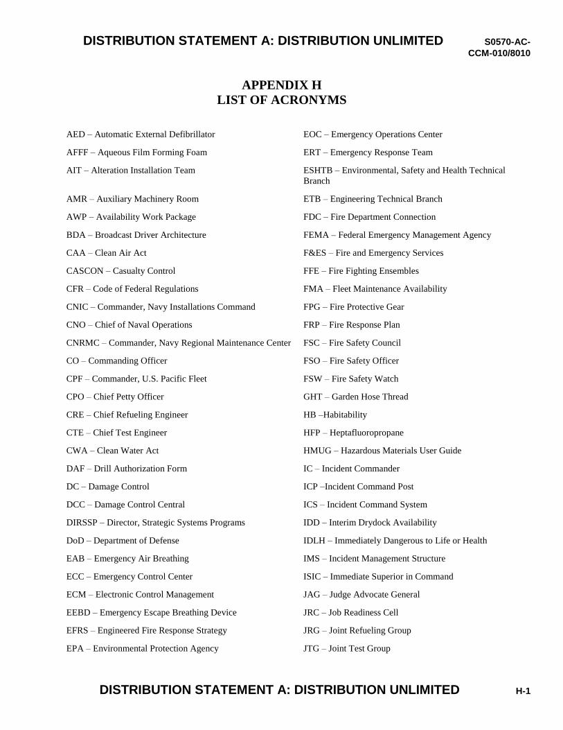
DISTRIBUTION STATEMENT A: DISTRIBUTION UNLIMITED S0570-AC-
CCM-010/8010
DISTRIBUTION STATEMENT A: DISTRIBUTION UNLIMITED H-1
APPENDIX H LIST OF ACRONYMS
AED – Automatic External Defibrillator EOC – Emergency Operations Center
AFFF – Aqueous Film Forming Foam ERT – Emergency Response Team
AIT – Alteration Installation Team ESHTB – Environmental, Safety and Health Technical
Branch
AMR – Auxiliary Machinery Room ETB – Engineering Technical Branch
AWP – Availability Work Package FDC – Fire Department Connection
BDA – Broadcast Driver Architecture FEMA – Federal Emergency Management Agency
CAA – Clean Air Act F&ES – Fire and Emergency Services
CASCON – Casualty Control FFE – Fire Fighting Ensembles
CFR – Code of Federal Regulations FMA – Fleet Maintenance Availability
CNIC – Commander, Navy Installations Command FPG – Fire Protective Gear
CNO – Chief of Naval Operations FRP – Fire Response Plan
CNRMC – Commander, Navy Regional Maintenance Center FSC – Fire Safety Council
CO – Commanding Officer FSO – Fire Safety Officer
CPF – Commander, U.S. Pacific Fleet FSW – Fire Safety Watch
CPO – Chief Petty Officer GHT – Garden Hose Thread
CRE – Chief Refueling Engineer HB –Habitability
CTE – Chief Test Engineer HFP – Heptafluoropropane
CWA – Clean Water Act HMUG – Hazardous Materials User Guide
DAF – Drill Authorization Form IC – Incident Commander
DC – Damage Control ICP –Incident Command Post
DCC – Damage Control Central ICS – Incident Command System
DIRSSP – Director, Strategic Systems Programs IDD – Interim Drydock Availability
DoD – Department of Defense IDLH – Immediately Dangerous to Life or Health
EAB – Emergency Air Breathing IMS – Incident Management Structure
ECC – Emergency Control Center ISIC – Immediate Superior in Command
ECM – Electronic Control Management JAG – Judge Advocate General
EEBD – Emergency Escape Breathing Device JRC – Job Readiness Cell
EFRS – Engineered Fire Response Strategy JRG – Joint Refueling Group
EPA – Environmental Protection Agency JTG – Joint Test Group
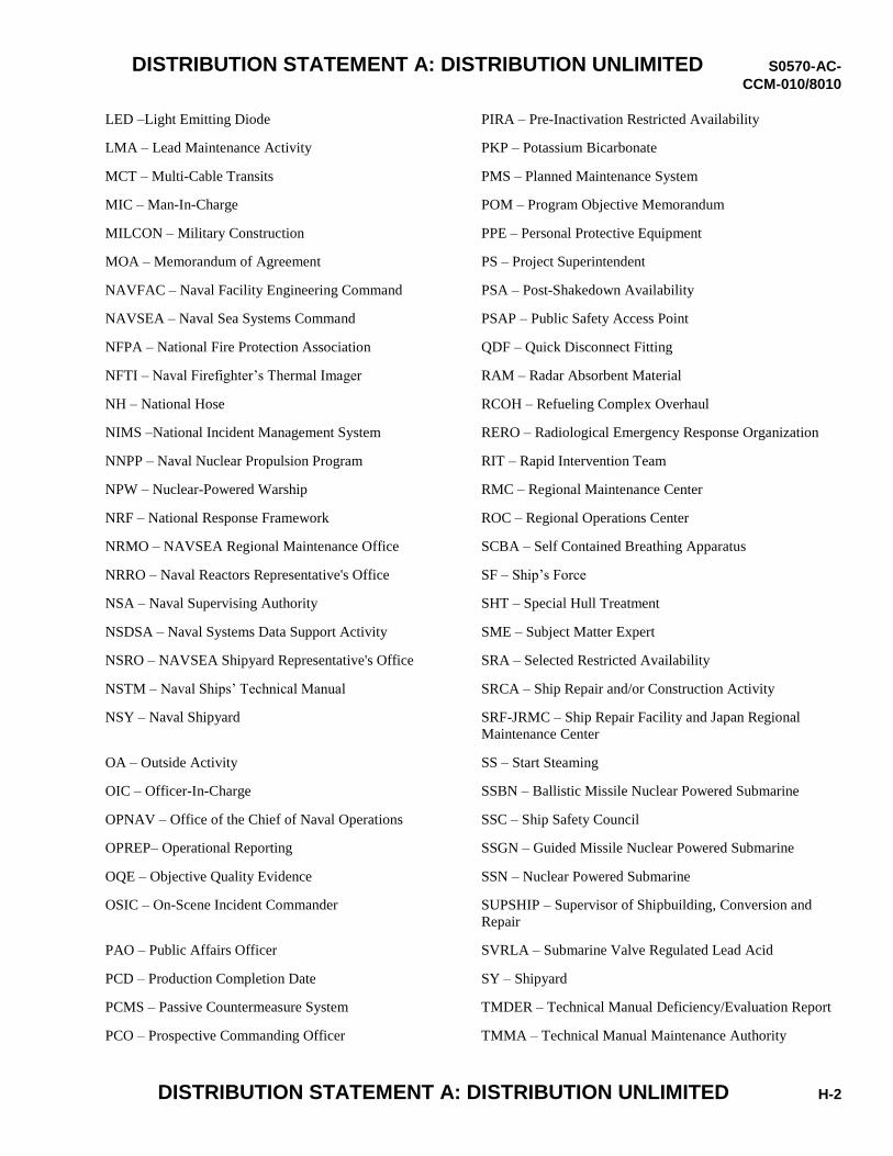
DISTRIBUTION STATEMENT A: DISTRIBUTION UNLIMITED S0570-AC-
CCM-010/8010
DISTRIBUTION STATEMENT A: DISTRIBUTION UNLIMITED H-2
LED –Light Emitting Diode PIRA – Pre-Inactivation Restricted Availability
LMA – Lead Maintenance Activity PKP – Potassium Bicarbonate
MCT – Multi-Cable Transits PMS – Planned Maintenance System
MIC – Man-In-Charge POM – Program Objective Memorandum
MILCON – Military Construction PPE – Personal Protective Equipment
MOA – Memorandum of Agreement PS – Project Superintendent
NAVFAC – Naval Facility Engineering Command PSA – Post-Shakedown Availability
NAVSEA – Naval Sea Systems Command PSAP – Public Safety Access Point
NFPA – National Fire Protection Association QDF – Quick Disconnect Fitting
NFTI – Naval Firefighter’s Thermal Imager RAM – Radar Absorbent Material
NH – National Hose RCOH – Refueling Complex Overhaul
NIMS –National Incident Management System RERO – Radiological Emergency Response Organization
NNPP – Naval Nuclear Propulsion Program RIT – Rapid Intervention Team
NPW – Nuclear-Powered Warship RMC – Regional Maintenance Center
NRF – National Response Framework ROC – Regional Operations Center
NRMO – NAVSEA Regional Maintenance Office SCBA – Self Contained Breathing Apparatus
NRRO – Naval Reactors Representative's Office SF – Ship’s Force
NSA – Naval Supervising Authority SHT – Special Hull Treatment
NSDSA – Naval Systems Data Support Activity SME – Subject Matter Expert
NSRO – NAVSEA Shipyard Representative's Office SRA – Selected Restricted Availability
NSTM – Naval Ships’ Technical Manual SRCA – Ship Repair and/or Construction Activity
NSY – Naval Shipyard SRF-JRMC – Ship Repair Facility and Japan Regional
Maintenance Center
OA – Outside Activity SS – Start Steaming
OIC – Officer-In-Charge SSBN – Ballistic Missile Nuclear Powered Submarine
OPNAV – Office of the Chief of Naval Operations SSC – Ship Safety Council
OPREP– Operational Reporting SSGN – Guided Missile Nuclear Powered Submarine
OQE – Objective Quality Evidence SSN – Nuclear Powered Submarine
OSIC – On-Scene Incident Commander SUPSHIP – Supervisor of Shipbuilding, Conversion and
Repair
PAO – Public Affairs Officer SVRLA – Submarine Valve Regulated Lead Acid
PCD – Production Completion Date SY – Shipyard
PCMS – Passive Countermeasure System TMDER – Technical Manual Deficiency/Evaluation Report
PCO – Prospective Commanding Officer TMMA – Technical Manual Maintenance Authority
DISTRIBUTION STATEMENT A: DISTRIBUTION UNLIMITED S0570-AC-
CCM-010/8010
DISTRIBUTION STATEMENT A: DISTRIBUTION UNLIMITED H-3
TR – Trouble Report
TRF – Trident Refit Facility
TYCOM – Type Commander
UFC – Unified Facilities Criteria
USFF – U.S. Fleet Forces Command
UL – Underwriters Laboratories
VAC – Volts Alternating Current
WIFCOM –Wirefree Communications
WRA – Waterfront Restricted Area

DISTRIBUTION STATEMENT A: DISTRIBUTION UNLIMITED S0570-AC-
CCM-010/8010
DISTRIBUTION STATEMENT A: DISTRIBUTION UNLIMITED H-4
THIS PAGE INTENTIONALLY LEFT BLANK.
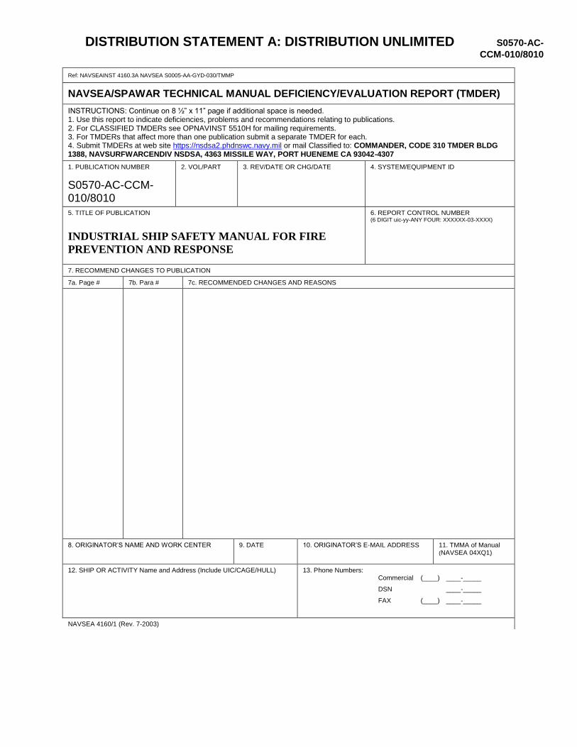
DISTRIBUTION STATEMENT A: DISTRIBUTION UNLIMITED S0570-AC-
CCM-010/8010
Ref: NAVSEAINST 4160.3A NAVSEA S0005-AA-GYD-030/TMMP
NAVSEA/SPAWAR TECHNICAL MANUAL DEFICIENCY/EVALUATION REPORT (TMDER)
INSTRUCTIONS: Continue on 8 ½” x 11” page if additional space is needed. 1. Use this report to indicate deficiencies, problems and recommendations relating to publications. 2. For CLASSIFIED TMDERs see OPNAVINST 5510H for mailing requirements. 3. For TMDERs that affect more than one publication submit a separate TMDER for each. 4. Submit TMDERs at web site https://nsdsa2.phdnswc.navy.mil or mail Classified to: COMMANDER, CODE 310 TMDER BLDG 1388, NAVSURFWARCENDIV NSDSA, 4363 MISSILE WAY, PORT HUENEME CA 93042-4307
1. PUBLICATION NUMBER
S0570-AC-CCM-010/8010
2. VOL/PART
3. REV/DATE OR CHG/DATE
4. SYSTEM/EQUIPMENT ID
5. TITLE OF PUBLICATION INDUSTRIAL SHIP SAFETY MANUAL FOR FIRE
PREVENTION AND RESPONSE
6. REPORT CONTROL NUMBER (6 DIGIT uic-yy-ANY FOUR: XXXXXX-03-XXXX)
7. RECOMMEND CHANGES TO PUBLICATION
7a. Page # 7b. Para # 7c. RECOMMENDED CHANGES AND REASONS
8. ORIGINATOR’S NAME AND WORK CENTER
9. DATE
10. ORIGINATOR’S E-MAIL ADDRESS
11. TMMA of Manual (NAVSEA 04XQ1)
12. SHIP OR ACTIVITY Name and Address (Include UIC/CAGE/HULL) 13. Phone Numbers: Commercial (____) ____-_____
DSN ____-_____
FAX (____) ____-_____
NAVSEA 4160/1 (Rev. 7-2003)