CCGS Henry Larsen Annual Drydocking and refit April 17 ...
178
F6855-123516 CCGS Henry Larsen Annual docking page 1 of 178 Saved as: larsen spec 2013.doc last amended: 13/02/13 CCGS Henry Larsen Annual Drydocking and refit April 17 – May 29, 2013.
Transcript of CCGS Henry Larsen Annual Drydocking and refit April 17 ...

F6855-123516 CCGS Henry Larsen Annual docking page 1 of 178
Saved as: larsen spec 2013.doc last amended: 13/02/13
CCGS Henry Larsen
Annual Drydocking and refit
April 17 – May 29, 2013.

F6855-123516 CCGS Henry Larsen Annual docking page 2 of 178
Saved as: larsen spec 2013.doc last amended: 13/02/13
Table of Contents PREAMBLE ................................................................................................................................... 4 HD-01 PRODUCTION CHART AND SUBCONTRACTORS ALLOWANCES .................... 10 HD-02 CONTRACTOR NOTIFICATION AND ACKNOWLEDGEMENT ............................ 12 HD-03 CONTRACTOR BASIC FAMILIARIZATION AND PJSA ......................................... 14 HD-04 PRE-REFIT SAFETY MEETING................................................................................... 19 HD-05 SERVICES....................................................................................................................... 21 HD-06 SEA TRIALS ................................................................................................................... 30 HD-07 DRYDOCKING............................................................................................................... 31 HD-08 DOCKING PLUGS ......................................................................................................... 33 HD-09 HULL BUTTS AND SEAMS ......................................................................................... 34 HD-10 HULL COATING ............................................................................................................ 35 HD-11 RUDDER STOCK, RUDDER & RUDDER TRUNK SURVEY ................................... 40
HD-12 SHIP SIDE DISCHARGE VALVES & SUCTION VALVES ....................................... 45 HD-13 VOID SPACES ................................................................................................................ 48 HD-14 BUBBLER PIPING REPAIRS ........................................................................................ 52 HD-15 BUBBLER PIPE ACCESS HATCH ............................................................................... 54 HD-16 BALLAST TANKS ......................................................................................................... 56 HD-17 FUEL OIL TANKS ......................................................................................................... 60 HD-18 SEA BAY/SEA CHEST ANODES ................................................................................. 64 HD-19 SEA BAY/SEA CHEST .................................................................................................. 67 H-01 SUPERSTRUCTURE COATING...................................................................................... 70 H-02 MIRANDA DAVIT ............................................................................................................ 72 H-03 LIFEBOAT DAVITS ......................................................................................................... 80 H-04 DECK CRANE QUINQUENNIAL SURVEY .................................................................. 89 H-05 HELICOPTER FUELING SYSTEM MAINTENANCE ................................................. 114
H-06 LIFERAFTS ..................................................................................................................... 119 H-07 ACCOMMODATION HVAC CLEANING .................................................................... 120 H-08 ACCOMMODATION WASHROOM EXHAUST DUCT CLEANING ........................ 122 H-09 GALLEY RANGE HOOD AND EXHAUST FAN TRUNKING ................................... 124 H-10 ASBESTOS REMEDIATION.......................................................................................... 127 H-11 LAUNDRY DRYER EXHAUST DUCTWORK CLEANING ....................................... 130 H-12 SEWAGE SYSTEM .......................................................................................................... 132
H-13 HULL, VOID SPACE & TANK SURVEY ...................................................................... 135 ED-01 TAILSHAFT WEARDOWN ......................................................................................... 139 ED-02 PORT TAILSHAFT ....................................................................................................... 140
ED-03 PORT STERNSEAL ...................................................................................................... 153 ED-04 STEERING GEAR SURVEY ........................................................................................ 155
E-01 ANCHOR WINDLASS SURVEY ................................................................................... 160 E-02 PROPULSION MOTOR MITCHELL BEARINGS ....................................................... 162
E-03 CENTRE MAIN ENGINE SUMP TANK CLEANING .................................................. 165 E-04 CYLINDER HEAD SERVICING .................................................................................... 168 E-05 CHARGE AIR COOLER HYDROSTATIC TESTING .................................................. 170
E-06 ELECTRICALLY DRIVEN PUMP OVERHAULS ........................................................ 171 E-07 ANNUAL REFRIGERATION SYSTEMS INSPECTION .............................................. 173 E-08 MACHINERY SPACE BILGE CLEANING ................................................................... 174

F6855-123516 CCGS Henry Larsen Annual docking page 3 of 178
Saved as: larsen spec 2013.doc last amended: 13/02/13
L-01 POWER PANEL INSTALLATION ................................................................................. 176
L-02 STEERING GEAR MOTORS .......................................................................................... 177

F6855-123516 CCGS Henry Larsen Annual docking page 4 of 178
Saved as: larsen spec 2013.doc last amended: 13/02/13
PREAMBLE 1. INTENT This specification outlines the work required for the 2012 Docking and annual refit of CCGS Henry Larsen. The period of work is April 17th – May 29th , 2013. All work specified herein and all repairs, inspections and renewals shall be carried out to the satisfaction of the Owner’s Representative and, where applicable, the attending TC Marine Safety Inspector. Unless otherwise specifically stated, the Owner’s Representative is the Chief Engineer. 2. MANUFACTURER’S RECOMMENDATIONS The overhaul and installation of all machinery and equipment specified herein shall be as per the manufacturer’s applicable instructions, drawings and specifications. The surface preparation, ambient limitations and coating applications shall be as per the manufacturer’s instructions and specifications. 3. TESTING AND RECORDS All test results, calibrations, measurements and readings are to be recorded. All tests are to be witnessed by the Inspection Authority, Technical Authority and where required, Transport Canada Marine Safety. The Contractor is responsible for contacting TC-MS when their presence is required for inspections or testing. The Contractor shall advise the Technical Authority in every case when Marine Safety arrives onsite for inspection of vessel’s equipments or structure. The recorded test results, calibrations, measurements and readings from the entire refit specification shall be provided in 3 typewritten binded reports on 8.5” X 11” paper. The binded reports shall be tabbed as per table of contents in the refit specification. The binded reports shall be provided to the Chief Engineer prior to the end of refit. The Contractor shall also provide reports/measurements/readings per individual specification item within the timeline indicated to the Chief Engineer. 4. WORKMANSHIP The contractor shall use fully qualified, certified and competent tradesmen and supervision to ensure a uniform high level of workmanship as judged by normally accepted shipbuilding standards and to the Owner’s satisfaction. 5. FACILITIES Quotation shall include all of the necessary labor and equipment required for the erection of access staging, rigging, lighting, tugs, pilotage, necessary cranage and line handling. 6. MATERIALS AND SUBSTITUTIONS All material shall be supplied by the contractor and all materials shall be new and unused unless otherwise specified. All replacement material in the form of jointing, packing, insulation, small hardware, oils, lubricants, cleaning solvents, preservatives, paints, coatings, etc., shall be in accordance with the equipment manufacturer’s drawings, manuals or instructions. Where no particular item is specified, or where substitution must be made, the Owner’s representative must approve all material offered.

F6855-123516 CCGS Henry Larsen Annual docking page 5 of 178
Saved as: larsen spec 2013.doc last amended: 13/02/13
7. REMOVALS Any items of equipment to be removed and subsequently reinstalled in order to carry out work specified or for access to carry out the work specified, shall be jointly inspected for damages prior to removal by both the contractor and Owner’s representative. 8. EXPOSURE AND PROTECTION OF EQUIPMENT The contractor shall provide adequate temporary protection for any equipment or areas affected by this refit. The contractor shall take proper precautions to maintain in a proper state of preservation any machinery, equipment, fittings, stores or items of outfit which might become damaged by exposure, movement of materials, sand grit or shot blasting, airborne particles from sand, grit or shot blasting, welding grinding, burning, gouging, painting or airborne particles of paint. Any damage shall be the responsibility of the contractor. Government furnished equipment and materials shall be received by the contractor and stored in a secure warehouse or storeroom having a controlled environment appropriate to the equipment as per the manufacturer’s instructions. 9. LIGHTING AND VENTILATION Temporary lighting and/or temporary ventilation required by the contractor to carry out any item of this specification shall be supplied, installed and maintained in a safe working condition by the contractor and removed upon the completion of work. 10. CLEANLINESS The contractor shall at all times, maintain the work areas in which his personnel have access in a clean condition and free from debris. Upon completion of this refit, the contractor shall ensure that the vessel is in a clean condition, free from all foreign material in any system or location placed there as a result of this refit. The contractor shall provide adequate temporary protection for any equipment or areas affected by this refit. The contractor shall dispose of any and all oil and water residue, which accumulates in the machinery space bilges as a result of any refit work detailed in this specification. 11. ASBESTOS Any and all insulation materials shall be asbestos free and approved for the required application. 12. ENTRY INTO ENCLOSED SPACES The contractor shall abide by the Coast Guard Enclosed Space Entry Policy. The policy is listed in the a Coast Guard’s Safety Management System, section 7.D.9 and section 7.D.9 (N). Entry certificates shall clearly state the type of work permitted and shall be renewed as required by the regulations. Additional copies of these certificates shall be posted in conspicuous locations for the information of ship and contractor personnel. A fire zone shall be established and naked lights shall not be used within this zone until “gas-free” certification has been issued. The Contractor is to ensure that any work carried out in confined spaces as defined by the Canada Labor Code Part II and complies fully with all provisions of the code. A number of spaces onboard the vessel are designated as Enclosed Spaces; these spaces are to be entered only under safe and controlled circumstances. The Contractor shall have in place an
F6855-123516 CCGS Henry Larsen Annual docking page 6 of 178
Saved as: larsen spec 2013.doc last amended: 13/02/13
Enclosed Space Entry Permit system, equal to or better than the procedure contained in the Coast Guard’s Safety Management System, section 7.D.9. Ship’s breathing apparatus and EEBD’s are not to be used except in an emergency. 13. SUSPENSION OF WORK The Technical Authority reserves the right to suspend work immediately when that work is being performed in contravention of the Coast Guard’s Safety Management System. Work shall be allowed to resume when the Technical Authority, in consultation with the Contractor and PWGSC, is satisfied that the agreed-upon procedures are in place and being adhered to. 14. HOTWORK Any item of work involving the use of heat in its execution requires that the contractor advise the owner’s representative prior to starting such heating and upon its completion. The contractor shall be responsible for maintaining a competent and properly equipped fire watch during and for one full hour after all hotwork. The fire watch shall be arranged such that all sides of surfaces being worked on are visible and accessible. The contractor shall provide sufficient suitable fire extinguishers and a fire watch during any such heating and until the work has cooled. Ship’s extinguishers shall not be used except in an emergency. The Contractor shall abide by the Coast Guard Hotwork Policy. The policy is listed in the Coast Guard’s Safety Management System , section 7.D.11 and section 7.D.11 (N). The contractor shall be responsible to ensure the contractor’s personnel including any subcontractors shall follow the policy. 15. LOCKOUT AND TAGOUT PROCEDURES 1. The Contractor shall be responsible to protect persons working onboard the vessel while working on or near shipboard systems and equipment from accidental exposure to:
- electrical currents - hydraulic - pneumatic - gas or stem pressure and vacuum - high temperatures - cryogenic temperatures - radio frequency emissions - potentially reactive chemicals - stored mechanical energy - equipment actuation
2. The contractor, under the supervision of the Chief Engineer and or the Electrical Officer, shall be responsible for the Lockout and Tagout of equipment and systems listed in the specification. 3. The Contractor shall supply and install all locks and tags and shall complete the Lockout Tagout Log sheet provided by the Vessel. 4. The Contractor shall remove all locks and tags and complete the Lockout Tagout Log sheet provided by the Vessel.

F6855-123516 CCGS Henry Larsen Annual docking page 7 of 178
Saved as: larsen spec 2013.doc last amended: 13/02/13
16. PAINTING All new and disturbed steelwork that will not be on the underwater wetted surface of the ship's hull is to be protected with two coats of Contractor supplied primer. Unless otherwise stated in the individual specification item, the primer is to be International Paints, Interplate Zinc Silicate NQA262/NQA026 red. The paint is to be applied as per the manufacturer's instructions on their respective product data sheets. Finish coats are described in individual specification items. 17. WELDING Welding shall be in accordance with the Canadian Coast Guard Welding Specifications for Ferrous Materials, Revision 4. (TP6151 E) The Contractor shall be currently certified by the Canadian Welding Bureau (CWB) in accordance with CWB 47.1 latest revision Division I, II or III at the time of bid closing. The Contractor shall provide a current letter of validation from the CWB indicating compliance with standard CSA W47.1, Division I, II or III. (latest revision) The Contractor may be required to provide approved procedure data sheets for each type of joint and welding position that will be involved in this refit. The Contractor may be required to supply a current Welders Ticket for each individual welder that will be involved in this refit. 18. SMOKING The Public Service Smoking Policy forbids smoking in all Government ships in areas inside the ship where shipyard personnel will be working. The contractor shall inform shipyard workers of this policy and ensure that it is complied with. 19. RESTRICTED AREAS The following areas are out of bounds to shipyard personnel except to perform work as required by the specifications: all cabins, offices, Wheelhouse, Control Room, Engineer’s office, public washrooms, cafeteria, dining room and lounge areas. 20. ELECTRICAL STANDARDS Any electrical installations or renewals shall be in accordance with the latest editions of the following marine standards: (a) TP 127E-TC Marine Safety Electrical Standards. (b) IEEE Standard 45 - Recommended Practice for Electrical Installation on Shipboard. If any cable installed within this contract is found to be damaged, shorted or opened as a result of the manner of installation, the entire length of cable shall be replaced and installed at no cost to the Department. Plastic tie-wraps may be used to secure wiring in panels or junction boxes only. 21. DRAWINGS All drawings and drawing revisions that the contractor is requested to do in the execution of this contract shall be of a quality equal to that of the drawings that are requested to be updated. For example, drawings that have been lettered and dimensioned in a professional manner shall not be updated using freehand. Prints and reproductions that a contractor is required to provide shall be made on one piece of paper.

F6855-123516 CCGS Henry Larsen Annual docking page 8 of 178
Saved as: larsen spec 2013.doc last amended: 13/02/13
Sign off and acceptance of jobs will not occur until any and all drawings are updated to the satisfaction of the Owner’s representative. 22. TRANSDUCERS The contractor shall not paint the transducers and all transducers shall be afforded the necessary protection during hull cleaning, blasting, burning, welding and coating operations. 23. OWNER’S REPRESENTATIVE Throughout this document, there is made reference to the Owner’s Representative. For the purpose of this document, the Owner’s representative is defined as the Chief Engineer of the Vessel. 24. Regulatory Authority Inspections The Contractor shall confirm a schedule of inspections with the regulatory authority (TCMS) for all work described in this specification and shall be responsible for calling them when inspections are required and for ensuring the work is credited by the regulatory authority in the Chief Engineer’s ‘Hull and Machinery Survey Book’. The contractor shall ensure the Chief Engineer is informed when the regulating authority is onsite such that the Chief Engineer can witness the inspections by the regulating authority. Notwithstanding any errors, omissions, discrepancies, duplication or lack of clarity in these project requirements, it shall be the responsibility of the Contractor to ensure that the execution of the work specified herein is to the satisfaction of the Technical Authority and the Inspection Authority. Inspection of any item by the Technical Authority does not substitute for any required inspection by Transport Canada Marine Safety (TC-MS) or by the Inspection Authority. 25. Waste Oil Products Disposal of waste oil products shall be carried out by the Contractor, or subcontractor, who has been licensed by provincial authorities for the disposal of petroleum products. Copies of certificates must be produced upon request. This must be in accordance with the Coast Guard Policy for Handling Fuel, Oil, and Waste Oil Products, which is part of the Fleet Safety Manual, section 7.C.3. a copy of which is in the attached safety annex. 26. WHMIS The contractor shall provide current MSDS sheets for any WHMIS-controlled products used onboard or around the vessel at the start of the work period before the products are used. This includes at the minimum MSDS sheets for any solvents, cleaners, chemicals, coatings and blasting grits to be used. Any neutralizing chemicals or specialized protective equipment required shall be provided by the Contractor at all times these WHMIS-controlled products are onboard the vessel. 27. SAFETY ANNEX The Contractor shall follow the Coast Guard Policies as outlined in the attached Safety Annex. This Annex contains excerpts from the Fisheries and Oceans Canada, Canadian Coast Guard

F6855-123516 CCGS Henry Larsen Annual docking page 9 of 178
Saved as: larsen spec 2013.doc last amended: 13/02/13
Fleet Safety Manual (DFO 5737) and deals with contractor responsibilities for items such as Hot Work, Confined Space Entry, Diving, Diving Operations and Dry-docking. An electronic copy of the Fleet Safety Manual (Adobe Acrobat .PDF version) can be found at http://142.130.14.20/fleet-flotte/Safety/main_e.htm
F6855-123516 CCGS Henry Larsen Annual docking page 10 of 178
Saved as: larsen spec 2013.doc last amended: 13/02/13
HD-01 PRODUCTION CHART AND SUBCONTRACTORS
ALLOWANCES Part 1: SCOPE: 1.1 The intent of this item is to provide a means for tracking the progress of the refit. Part 2: REFERENCES: N/A Part 3: TECHNICAL DESCRIPTION: 3.1 The successful Contractor shall supply three copies of a detailed bar chart showing the planned work schedule for the ship's refit. This bar chart shall show, for each spec. item, the start date, the manpower loading, the duration and the completion date. The chart is also to highlight any critical paths. 3.2 The production chart shall be updated weekly or for each production meeting to reflect the actual production on the refit and changes to the anticipated completion dates of each individual item.
3.3 The production chart shall clearly indicate the arrival/departure dates of any Subcontractors/Field Service Representatives. 3.4 The production chart shall include the status and production on each 1379 arising. 3.5 Three copies of the production chart shall be given to the Chief Engineer the day prior to each Production Meeting. A copy shall be emailed to the Project Authority, [email protected] the day prior as well. 3.6 A copy of the original bar chart shall be provided via email to the PWGSC contracting Officer and Project Authority before the close of business on the day of the ships arrival at the Contractors premises. Subcontractors with Allowances 3.7 The Contractor shall provide a weekly update of the hours billed by the subcontractors along with their hourly rates. 3.8 The results shall be tabulated in an excel spreadsheet clearly indicating the Subcontractor, date(s), hours worked and hourly rate for the hours worked. 3.9 The update is to be emailed to, Contracting Officer and Project Authority the day prior to the weekly scheduled Progress Meeting.

F6855-123516 CCGS Henry Larsen Annual docking page 11 of 178
Saved as: larsen spec 2013.doc last amended: 13/02/13
Part 4: PROOF OF PERFORMANCE: N/A Part 5: DELIVERABLES 5.1 Contractor shall provide a weekly production chart and excel spreadsheet for subcontractor allowances every week on the timelines indicated.
F6855-123516 CCGS Henry Larsen Annual docking page 12 of 178
Saved as: larsen spec 2013.doc last amended: 13/02/13
HD-02 CONTRACTOR NOTIFICATION AND ACKNOWLEDGEMENT 1) General Requirements: 2) References: Complete Title, drawing number and revision number.
DFO 5737 Fleet Safety and Security Manual sect 7.F.8 CONTROLLING ASBESTOS-CONTAINING MATERIALs CCGS Henry Larsen Asbestos Management Program
3) Government Furnished Equipment. 4) Contractor Furnished Equipment. 5) Regulatory Requirements.
DFO 5737 Fleet Safety and Security Manual sect 7.F.8 CONTROLLING ASBESTOS-CONTAINING MATERIALS CCGS Henry Larsen Asbestos Management Program
6) Coordination with other Specification Items.
This item will apply to all items in the Specification.
7) Safety Precautions
CGG has identified the presence of various nonfiable asbestos materials in the CCGS Henry Larsen. An asbestos inventory report showing the locations and amounts of these materials is available for viewing from the Asbestos Coordinator (AC)or their designate.
8) Statement of Work (include detailed location information i.e. frame number, compartment etc.)
The attached Contractor Notification And Acknowledgement Form is to be completed and signed by the Contractor and delivered to the Asbestos Coordinator (AC) before any work commences. The Contractor is responsible to ensure the Contractor’s workers and sub-contractors and subcontractor’s workers are aware of the presence of various non-friable asbestos materials in the CCGS Henry Larsen and inform the AC before undertaking any work described in the Contractor Notification and Acknowledgement Form.

F6855-123516 CCGS Henry Larsen Annual docking page 13 of 178
Saved as: larsen spec 2013.doc last amended: 13/02/13
F6855-123516 CCGS Henry Larsen Annual docking page 14 of 178
Saved as: larsen spec 2013.doc last amended: 13/02/13
HD-03 CONTRACTOR BASIC FAMILIARIZATION AND PJSA Part 1: SCOPE:
The Contractor shall ensure that they disclose any pertinent information, agree to follow all applicable laws, and comply with the requirements of the FSSM; and in particular that Contractor’s employees and/or subcontractors engaged in general housekeeping, maintenance and/or repair activities must not commence work until they have received the familiarization contained in Annex B and completed a pre-job safety assessment (PJSA).
Part 2: REFERENCES: Standards: Fleet Safety and Security Manual sect 10.A.2 Owner Furnished Equipment The contractor shall supply all materials, equipment, and parts required to perform the specified work unless otherwise stated. Part 3: TECHNICAL DESCRIPTION:
3.1 The Contractor will arrange with the vessel for a Contractor Basic Safety Familiarization for the Contractor’s supervisory staff to be given by Coast Guard before any work commences. The familiarization will consist of a basic tour of the vessel in locations where the Contractor will be working.
3.2 Following the initial Contractor Basic Safety Familiarization it will be the
Contractor’s responsibility to provide the Contractor’s workers and any subcontractors and the subcontractors workers with a Contractor Basic Safety Familiarization.
3.3 The Contractor will ensure completed copies of all Contractor Basic Safety
Familiarization forms are provided to Coast Guard.
3.4 The Contractor is to ensure the Contractor’s workers and any subcontractors and the subcontractors workers complete a pre-job safety assessment (PJSA). The Contractor’s or subcontractors own PJSA may be used provided it meets the requirements of the attached PJSA.
3.5 The Contractor will ensure completed copies of all PJSA forms are provided to
Coast Guard.
F6855-123516 CCGS Henry Larsen Annual docking page 15 of 178
Saved as: larsen spec 2013.doc last amended: 13/02/13
Part 4: PROOF OF PERFORMANCE:
Inspection Coast Guard reserves the right to monitor Contractor compliance. All work shall be completed to the satisfaction of the Chief Engineer.
Part 5: DELIVERABLES: Completed Contractor Basic Safety Familiarization forms. Completed Pre Job Safety Assessments (PJSA) forms

F6855-123516 CCGS Henry Larsen Annual docking page 16 of 178
Saved as: larsen spec 2013.doc last amended: 13/02/13

F6855-123516 CCGS Henry Larsen Annual docking page 17 of 178
Saved as: larsen spec 2013.doc last amended: 13/02/13

F6855-123516 CCGS Henry Larsen Annual docking page 18 of 178
Saved as: larsen spec 2013.doc last amended: 13/02/13

F6855-123516 CCGS Henry Larsen Annual docking page 19 of 178
Saved as: larsen spec 2013.doc last amended: 13/02/13
HD-04 PRE-REFIT SAFETY MEETING Part 1: SCOPE: The intent of this specification shall be to have a Pre-Refit Safety Meeting with the Contractor to discuss and agree on the methodology to be used by the Contractor and vessel to meet the requirements of the Canada Labour Code and Canadian Coast Guard Fleet Safety and Security Manual with regard to Safety during the refit period. Part 2: REFERENCES: Standards Canada Labour Code
Canadian Coast Guard Fleet Safety and Security Manual
Owner Furnished Equipment The contractor shall supply all materials, equipment, and parts required to perform the specified work unless otherwise stated. Part 3: TECHNICAL DESCRIPTION:
3.1 Prior to the pre-refit meeting, the successful contractor is to provide his company
Safety Plan pertaining to this contract and addressing the CCG Safety regulations
and the Canada Labour Code in place.
3.2 The contractor shall comply with the work requirements as outlined in the Canada
Labour Code and applicable provincial regulations.
3.3 The contractor shall note that Canadian Coast Guard ships are presently working
under the ISM code and each ship has a Fleet Safety Manual onboard. The Fleet
Safety Manual will be adhered to when contract work involves CCG personnel
and any other Public Service Employee during the contract period. Following are
the listings of the applicable work instructions:

F6855-123516 CCGS Henry Larsen Annual docking page 20 of 178
Saved as: larsen spec 2013.doc last amended: 13/02/13
7.B.2 FALL PROTECTION
7.D.9 ENTRY INTO ENCLOSED SPACES pgs 131 to 136
7.D.9 (N)ENTRY INTO ENCLOSED SPACES – WORK INSTRUCTION
7.D.11 HOTWORK pgs 139 to 146 incl.
7.D.11 (N)HOTWORK – WORK INSTRUCTIONS.
7.F.1 HANDLING FUEL, OIL AND WASTE OIL PRODUCTS
7.F.6 HANDLING STORAGE AND DISPOSAL OF HAZARDOUS MAT’LS
7.F.9 PAINT AND OTHER COATINGS pg 235
7..D.19 LOCKOUT AND TAG OUT pgs 189 to 192 incl.
7.F.8 CONTROLLING ASBESTOS-CONTAINING MATERIALS
10.A.2 CONTRACTOR SAFETY AND LIABILITY
3.4 Prior to any work beginning the Contractor’s Safety person and Coast Guard Safety Person representatives including Coast Guard Loss Prevention, the technical authority, Commanding Officer will meet to agree on how the requirements will be met and how the paperwork will be handled.
3.5 This will include but may not be limited to the items listed above.
3.6 All work is to be to the satisfaction of the Chief Engineer.
Part 4: PROOF OF PERFORMANCE: Inspection
All work shall be completed to the satisfaction of the Chief Engineer. Part 5: DELIVERABLES:
Completed Safety Management Systems forms delivered to Chief Engineer.

F6855-123516 CCGS Henry Larsen Annual docking page 21 of 178
Saved as: larsen spec 2013.doc last amended: 13/02/13
HD-05 SERVICES
The following services are to be supplied and connected to the vessel in drydock and
afloat during the refit period and disconnected upon leaving. The Contractor is to supply
all material to point of onboard connection. The Contractor's quote is to include all
cranage/scaffolding required for connection/disconnection. The Contractor will be
responsible for any additional connections required as a result of the ship being shifted
between berths and to the drydock. Global and daily rates are to be quoted.
The bid price is to be broken down by item.
.1 Berthing: During refit, while not in dock, vessel to be berthed at Contractor's wharf at a
safe and secure berth with adequate water at extreme low tide to ensure that the vessel
will not touch bottom.
i. Contractor is to include in quote all costs for initial tying up, any
movement of the vessel during refit and letting go of lines from
Contractor's wharf on departure of vessel from yard upon completion of
refit.
ii. The contractor is to note that once the refit starts the vessel cannot move
or turn around under her own power.
.2 Gangways: Labour and services to be supplied to rig and supply on board two (2)
gangways while in drydock, complete with safety nets and handrails. While alongside,
one (1) gangway is required. Gangways are to be maintained safe and structurally
suitable for the passage of ship’s crew and workmen as per MOSH Regulations, Section
2.
i. Gangways to be well lighted at night.

F6855-123516 CCGS Henry Larsen Annual docking page 22 of 178
Saved as: larsen spec 2013.doc last amended: 13/02/13
ii. The gangways are to be at opposite ends of the vessel as directed by the
Commanding Officer.
.3 Potable Fresh Water: Potable water shall be supplied through a fresh water filling line
with a pressure reducing valve and pressure gauge at the ship's fresh water filling
connection located on the Upper Deck, frame 29, port or stbd side.
i. Approximately eight cubic meters of fresh water per day shall be
provided.
ii. Contractor to supply any fresh water used for cleaning, testing or flushing
of tanks as required by the specification in addition.
iii. The contractor is to provide test results from within the past month
indicating that the water meets provincial drinking water standards before
the connection is made to the vessel.
.4 Fire Main: Water shall be supplied to the vessel's fire main system at a pressure of 550
kPa (80 psi) and be continuous 24 hours per day, using two (2) hoses. The hoses shall be
connected to the ship's international shore connection located on the Upper Deck, frame
100 (port and starboard side).
i. A pressure reducing valve with pressure gauge shall be fitted before the
shore connection valve on board the ship.
ii. Water flow shall be sufficient such that fully opening any 2 fire station
hoses on the ship will result in no noticeable reduction in flow.
.5 Cooling Water Connections: While the ship is in drydock, the Contractor is to connect
and fit three (3) 38mm (1½") dia. cooling water connection hoses, to the Central Cooling
System. One supply hose to be connected to the 1-1/2” SW connection located at the
F6855-123516 CCGS Henry Larsen Annual docking page 23 of 178
Saved as: larsen spec 2013.doc last amended: 13/02/13
P&S Fuelling Stations, Upper Deck. Another supply hose is to be run between the 1-1/2”-
3-way changeover valve located on the Portside AG1 Room (labeled Drydock Central
Cooling Supply) and the 2-1/2” inlet valve located in way of AG1 Stbd, side. An outlet
hose is to be run from the Central Cooling plate coolers outlet piping to overboard in the
most convenient location.
i. Pressure to be supplied through a pressure reducing valve with gauge at
350 kPa (50 psi).
ii. Hoses to be removed ashore upon completion of drydocking.
.6 Sewage Connection: a 100mm diameter sewage overboard discharge, located at frame 85
starboard side, requires to have a connection pipe welded to the shell with hose attached
on free end to lead sewage away from the ship's side to Contractor's sewage outlet.
.7 Oily Bilge Water: Contractor to quote on removing from ship's bilges approximately
twenty cubic meters of oil/water mixture. Quote unit cost for each additional cubic meter.
For estimation purposes, quote as 25% oil, and 75% water.
i. This item is to be adjusted up or down upon proof of invoice. The
quantities in this item are for the vessel’s requirements and are not to be
included with the Contractor’s requirements for completion of items in
this specification.
ii. Contractor to provide identity of firm(s) licensed for pumping and disposal
of waste oil.
.8 Electrical Shore Power: Shore power facilities to be supplied to ship through two
parallel fed 600 VAC, 60 hz.,3 ph., 400 ampere cables fed from a single minimum 800
amp source. Contractor supplied cables and fittings are to be used. Cables to be spliced
into two (2) owner supplied female shore power plugs and insulated. Cables and

F6855-123516 CCGS Henry Larsen Annual docking page 24 of 178
Saved as: larsen spec 2013.doc last amended: 13/02/13
connections are to be Megger tested prior to hook up. Plugs to be connected to two (2)
male plugs at the shore power connection box on the aft end of the Upper Deck.
i. Contractor to quote for supplying 8,000 KW hours per day times (X) the
number of days scheduled for refit.. Contractor to quote KWH unit rate
for adjustment purposes.
ii. Upon completion of refit and removal of shore power, the plugs are to be
disconnected from cables and turned over to the ship’s Electrical Officer.
iii. Pigtails on plugs are not to be cut when disconnecting from shore power
cables.
iv. Meter readings to be taken from the ship's shore power meter located in
the Control Room. Meter readings to be recorded by the Contractor and
the ship's Electrical Officer at the time of connection and disconnection.
v. Contractor is advised that the ship requires shore power from the starting
date to the completion date of the contract. The power quoted is for the
vessel’s own use.
vi. The contractor is to provide prior to the closing of bids, written proof of
capability of providing shore power requirements as stated in the
specification for the duration of the drydock period.
vii. NOTE: If Contractor is supplying power to the ship by means of a diesel
generator set on the dock, contractor is responsible for any watchkeeping
personnel or fuel for the generator unit.

F6855-123516 CCGS Henry Larsen Annual docking page 25 of 178
Saved as: larsen spec 2013.doc last amended: 13/02/13
F6855-123516 CCGS Henry Larsen Annual docking page 26 of 178
Saved as: larsen spec 2013.doc last amended: 13/02/13
.9 Garbage Removal: Garbage containers of 215 cu. ft. (6 m3_) minimum capacity shall be
provided and used. Contractor to remove garbage from work areas on the ship on a daily
basis. This includes all sludge and scale from tank cleaning. The Contractor is
responsible for provision of suitable containers and any costs associated with waste
disposal regulations that may be in place. This will include hazardous materials. The
Contractor is to advise of any such provincial or federal regulations or practices at the
Pre-Refit Meeting.
i. Cost of cranage and haulage to be included in quotation. Garbage
container to be placed in a suitable location agreed upon by the Contractor
and the Chief Engineer.
.10 Telephones: Four (4) independent and private telephone lines are to be supplied. Cost of
connection, service and removal to be included in bid price. The telephone connections
shall be supplied to the ship and connected at the Quartermaster Stations located at the
Upper Deck, frame 137, port & starboard side. Telephone connections to be installed as
follows:
i. One connection to ship's telephone exchange;
ii. One connection to Commanding Officer's telephone;
iii. One connection to the Chief Engineer's telephone.
iv. One connection to the Logistics Officer’s telephone.
v. All telephones to be active 24 hours a day for the duration of the contract.
Lines are to have long distance dialing capabilities, the costs of which will
be dealt with upon proof of separate invoice.
vi. Should landlines not be available, the Contractor is to provide sufficient
cellular phones in lieu.

F6855-123516 CCGS Henry Larsen Annual docking page 27 of 178
Saved as: larsen spec 2013.doc last amended: 13/02/13
vii. The Contractor shall be responsible for giving notice for
connection/disconnection times to Telephone Company as required for
any ship movements during the drydocking period.
viii. Contractor to supply listing of shipyard telephone numbers, fire, police
and emergency telephone numbers to Chief Engineer when vessel arrives
in Contractor's yard.
ix. Long distance charges to be billed directly to:
Canadian Coast Guard
P.O. Box 5667
St. John,s, NF
A1C 5X1
Attn: CCGS HENRY LARSEN
.11 Deck Protection: Alleyways throughout the ship including the Wheelhouse and all
stairways shall be covered with _" (3mm) masonite panels or a suitable alternative
(Flame Retardant Magafilm 15LS-FR, or equal. Contact: Milrail Inc., 1812 Gagnon,
Lachine, Quebec, H8T 3M6, Tel. (514)633-8710).
i. All edges and joints are to be securely taped down. Any deck coverings
damaged during the course of the refit are to be replaced.
ii. Areas to be covered:
1. Main Deck: starting at frame 30 up to frame 165, both sides including all
cross alleyways and cabin entranceways, excluding Galley, Crew's Cafeteria
and Pantry area. Total area = 200 sq. m. (2150 sq. ft.).

F6855-123516 CCGS Henry Larsen Annual docking page 28 of 178
Saved as: larsen spec 2013.doc last amended: 13/02/13
2. Upper Deck: starting at frame 121 up to frame 139, both sides and
including all cross alleyways and Engineer's Office. Total area = 117 sq. m.
(1264 sq. ft.).
3. Boat Deck: starting at frame 121 to frame 139, both sides and cross
alleyways. Total area = 31 sq. m. (336 sq. ft.).
4. Officers' Deck: starting at frame 121 up to frame 139 both sides and cross
alleyway. Total area = 28 sq. m. (305 sq. ft.).
5. Navigation Bridge Deck: Starting at frame 113 to frame 149 including
complete carpeted area of Wheelhouse and passageway to Special
Navigation Room. Total area = 100 sq. m. (1100 sq. ft.).
6. Stairways: Total area = 40 sq. m. (430 sq. ft.).
7. Cabins: Contractor to quote on covering the decks in six cabins:
Commanding Officer, Chief Engineer, Senior Engineer, Senior Electrician,
Chief Officer and Spare Cabin. Total area for cabins = 35 sq. m.
iii. Contractor to quote a unit price per square meter for adjustment purposes.
iv. All deck coverings are to be removed from the ship and taken ashore on
completion of work. Contractor to ensure all tape marks on deck caused by
securing protective coverings to deck are cleaned from all decks and stairs.
.12 Cranage: Crane and operator usage for vessel's purpose; quote for 35 lifts and unit cost
per lift. Also quote hourly rate for services of crane, operator and spotter. Adjustments
to total number of lifts will be by 1379 action

F6855-123516 CCGS Henry Larsen Annual docking page 29 of 178
Saved as: larsen spec 2013.doc last amended: 13/02/13
.13 Television: One cable television connection to the ship’s internal system to be connected
as directed by the ship's Electrical Officer. Cost of connection, service and removal to be
included in quote. In the event that cable television is not available, the contractor is to
provide a home satellite television system, complete with service costs, for the duration
of time cable television is unavailable.

F6855-123516 CCGS Henry Larsen Annual docking page 30 of 178
Saved as: larsen spec 2013.doc last amended: 13/02/13
HD-06 SEA TRIALS
Part 1: SCOPE:
The intent of this item is to provide for a test of worked on equipment under operational
conditions.
Part 2: REFERENCES: Specification items
Part 3: TECHNICAL DESCRIPTION:
3.1 On completion of all specification items, sea trials will be carried out as a functional test
of the ship's propulsion and other systems:
Part 4: PROOF OF PERFORMANCE:
4.1 Sea trials will last a minimum of four (4) hours.
4.2 Trials will contain ahead and astern movements at various power levels.
4.3 Trials will be carried out to the satisfaction of the Chief Engineer. Acceptance will not be
signed off by CCG until these trials are successfully completed.
4.4 The Contractor is to have sufficient supervisory staff on board, during these trials to
witness the operation of machinery which he has worked on during this refit.
Part 5: DELIVERABLES 5.1 The Contractor shall provide a report of the readings and findings during the seal trial
period.

F6855-123516 CCGS Henry Larsen Annual docking page 31 of 178
Saved as: larsen spec 2013.doc last amended: 13/02/13
HD-07 DRYDOCKING
Vessel Particulars:
Length O.A. 99.80 m
Length B.P. 93.80 m
Breadth Overall 19.78 m
Depth Moulded 8.08 m
Mean Draft, Extreme 7.24 m
Displacement, Extreme 8290 tonnes
Displacement, Docking 6200 tonnes
1. A docking plan is available on board the vessel. Contractor will be responsible to ensure
drawing is returned to vessel upon completion of work.
2. Drydocking is to take place immediately upon the ship arriving at the shipyard to
commence refit.
3. Contractor to prepare blocks and necessary shoring to maintain true alignment of the
vessel's hull and machinery throughout the drydocking period. Contractor to dock and
undock vessel and allow sufficient laydays to perform both the work described in this
specification with reasonable time allowance to deal with any work arisings. Contractor
is to quote total number of laydays and unit cost per layday.
4. The vessel is to be docked so that all docking plugs, transducers, anodes and sea inlet
grids are clear and accessible. A minimum clearance of 4' (1.22 m) is to be available
below the keel. If any hull fittings are covered, the Contractor is responsible for all
labour and materials required for making alternative arrangements to drain tanks and/or
move blocks to gain access to areas of specified work.

F6855-123516 CCGS Henry Larsen Annual docking page 32 of 178
Saved as: larsen spec 2013.doc last amended: 13/02/13
5. The Contractor shall be responsible for the safe transfer of the ship from its pre-docking
berth or location onto its docking blocks. During docking, radio contact is to be
maintained between the vessel's Commanding Officer and the Contractor's Docking
Master. The Contractor is to include in his bid, tug and/or pilotage, and ice clearing
services as required. All costs for line handling and Qualified Docking Master are the
responsibility of the contractor.
6. Within two hours of docking, the underwater hull is to be cleaned by high pressure fresh
water washing (2000 PSI minimum) to remove all marine growth and allow preliminary
inspection.
7. Prior to commencing hydro blasting, all hull mounted equipment and openings are to be
fully protected.
8. The following information is to be recorded on Ship Condition Reports:
9. Prior to docking, all tanks on vessel to be sounded and contents recorded. Copy to be
signed by the ship's Commanding Officer, the Chief Engineer and Contractor's Docking
Master.
10. On docking, all tanks emptied to be listed, and copies held by Contractor and Chief
Engineer.
11. At undocking, all tanks to be refilled to obtain same draft and trim as at docking, and
condition agreed by the Docking Master, the ship's Commanding Officer and the Chief
Engineer.
12. The Contractor is not to remove or transfer any tank contents without first discussing
same with the Chief Engineer. At least four hours notice is to be given.

F6855-123516 CCGS Henry Larsen Annual docking page 33 of 178
Saved as: larsen spec 2013.doc last amended: 13/02/13
HD-08 DOCKING PLUGS
1. Contractor shall remove the following docking plugs to drain water accumulation. All
docking plugs removed shall be tagged immediately after removal, stored in a suitable
container and given to the Chief Officer. A ship's Officer is to be present when docking
plugs are removed and reinstalled. Locations of the plugs are shown on docking plan:
Discharge Sea Bay (Fr. 84, centerline)
Suction Sea Bay (Fr. 87, centerline)
Aft Peak Tk (Fr G)
Fwd. Stability Tk (Fr.140 P & S)
Aft Stability Tank (Fr.127 P & S)
Aft Trim Tank (Fr. 16)
Note: Docking plugs for water ballast and void tanks are 25mm (1") square recessed. Docking
plugs for fuel oil/lube oil tanks are 19mm (3/4") square recessed.
2. Tap to be run over threads in hole. Docking plug threads to be cleaned on a lathe if
required. Contractor to quote on thread cleaning 6 docking plugs in lathe. No docking
plugs are to be removed from water ballast tanks until tanks have been pumped as low as
possible by ship's personnel.
3. Any docking plugs removed will require openings to be temporarily filled with wood
plugs during operations such as sandblasting, painting, etc. which could cause
contamination of tanks to occur.
4. After tanks have been drained, and at the direction of the Chief Engineer, all docking
plugs are to be installed using new sealing thread and white lead.

F6855-123516 CCGS Henry Larsen Annual docking page 34 of 178
Saved as: larsen spec 2013.doc last amended: 13/02/13
HD-09 HULL BUTTS AND SEAMS
1. Hull plate welding butts and seams to be repaired will be determined at the time of the
hull survey by the TCMS representative and the Chief Engineer.
2. Seams and butts selected for repair are to be marked, cleaned to sound metal by air arc or
grinding and brought up to original level by approved welding techniques and materials.
3. The contractor is to bid on 1500 linear feet of gouging and 1000 linear feet of grinding
and unit cost for each.
4. Amount of gouging and/or grinding will be adjusted by 1379 action.
5. Contractor to use welding rods suitable for use with Grade EH-36 steel. Suggested rod
size- 3/16”
6. Contractor to quote on 7,500 bead feet of weld, plus a rate per bead foot for adjustment
purposes.
7. Following any seam repairs the surface profile must be prepared for hull coating as per
The Hull coating specification item.
8. Butts and seams falling in way of any fuel tanks will require fuel tank to be gas freed and
certified safe for hot work.
9. Butts and seams falling in ballast/void tanks that are painted will require interior paint
work to be touched up in way of damage. This will be addressed by PWGSC 1379
action.
10. All work to be to the approval of Transport Canada Marine Safety and the Chief
Engineer.

F6855-123516 CCGS Henry Larsen Annual docking page 35 of 178
Saved as: larsen spec 2013.doc last amended: 13/02/13
HD-10 HULL COATING
1. To be done in conjunction with the drydocking of the vessel.
2. Coast Guard will be retaining the services of an independent consultant to verify that the
surface preparation and coating; storage, preparation, and application are as per the
specification.
3. Payment for the consultant will be directly by Coast Guard outside of this contract.
4. The contractor is to allow safe access to areas where work is being performed under this
specification including storage and mixing areas as the consultant deems necessary for
the purpose of verifying that the surface preparation and coating; storage, preparation,
and application are as per the specification.
5. The underwater hull up to Main Deck level (8.08m above Keel) including rudder and
rudder trunk to be cleaned by hydro-blast (high pressure fresh water, 2000 psi minimum)
of all loose rust and marine growth .
6. All staging, cranage, screens, heaters and other environmental control equipment, lighting
and any other support services, equipment and material necessary to perform the tasks set
out in this specification shall be supplied by the Contractor.
7. Suitable storage facilities for the materials and equipment shall be provided close to the
work site. These facilities shall be maintained at a temperature recommended by the
paint manufacturer as necessary to ensure ease of preparation and application of the paint.
8. The area to be dealt with is 2700 m². After completion of cleaning the underwater area is
to be inspected for loose paint and bare areas.
F6855-123516 CCGS Henry Larsen Annual docking page 36 of 178
Saved as: larsen spec 2013.doc last amended: 13/02/13
9. The above water hull from the waterline to the top of the bulwarks, 1120m² is to be
cleaned by high pressure wash to remove all loose rust and peeling coatings.
10. The entire hull area is then to be inspected by the Chief Engineer and the attending TC
Marine Safety Inspector.
11. The Contractor shall ensure that no damage, unnecessary cleaning or repairs, result from
abrasive blasting and/or the application of coatings. Grit used for blast cleaning shall not
be permitted to enter into any part of the vessel. The Contractor is to ensure that each
and every opening into the vessel where sand or grit may gain ingress and cause damage
shall be suitably protected, including the following:
stern tubes;
sea bays, sea chests;
all overboard discharge valves;
3 main engine air intake plenums;
engine room supply & exhaust fans;
tank vents (note - caution to be used on any tanks that are being cleaned and vented during this
time);
rudder gland in rudder trunk void.
12. Measures shall also be taken to ensure that application of coatings does not take place to
surfaces or equipment other than those areas specified, and that any inlets or discharges
in the shell shall not be blocked by the coating. All deck machinery shall be protected
against grit, dust and coatings where necessary.
13. The Contractor shall plug deck scuppers and discharges or take any measures necessary
to prevent water or other liquids from contaminating the areas of plating being coated or
prepared for coating.

F6855-123516 CCGS Henry Larsen Annual docking page 37 of 178
Saved as: larsen spec 2013.doc last amended: 13/02/13
14. The following are to be suitably protected against damage during cleaning of the hull,
abrasive blasting and application of new coatings. The Contractor will be responsible for
repair/replacement of any damaged items at the Contractor’s expense to the satisfaction
of the Owner's Representative.
All hull mounted equipment including:
anodes (6),
reference electrodes (2),
echo sounders (2),
speed log (1),
15. The area around the six impressed current anodes, (approx. 3 metre diameter each) is to
be blasted to the required Sa 2-1/2. A dialectric resistance filler such as International Red
Hand or equivalent, is to be trowelled-on and faired from approximately 100 mil down to
30 mil. This area is then to be covered as per the rest of the hull as detailed in the
specification.
16. The "Skarpenord" drawing showing locations will be supplied by the ship’s Senior
Electrical Officer.
17. In conjunction with this work, the Jastram service representative (supplied under HD-18
Sea Bays) is to be retained to check out the impressed current system while attending to
the sea bays.
18. All areas of loose paint and/or bare steel shall be abrasive blast cleaned to minimum
SSPC-SP-10. If oxidation occurs between blasting and application of Intershield 300, the
surface must be reblasted to the specified visual standard prior to application of
Intershield 300, with edges feathered back to a firm edge, a minimum of 300mm, and
blown clean with compressed air. Surface profile to have a minimum roughness of 3
mils. Contractor to ensure rudder trunk void is blasted for coating. (Protection to be
supplied for gland area to prevent grit from entering packing gland.) The intact existing
hull coating is to be sand swept to provide an anchor pattern for the new coating.

F6855-123516 CCGS Henry Larsen Annual docking page 38 of 178
Saved as: larsen spec 2013.doc last amended: 13/02/13
19. On completion of abrasive blasting, affected hull areas are to be surveyed by the
Contractor's Representative and Chief Engineer and surface area of bared steel agreed
upon and recorded. They will also agree to the total area to be coated, so that the total
cost of coating can be adjusted up or down from the bid price.
20. Areas where Interguard KZA 377 is to be applied over existing coatings which are intact
and strongly bonded to be the shell plating are to be sweep blasted to provide a 3mm
profile. The intact coating will have a dull pink or grey colour after sweep blasting
depending on whether the existing paint is red or black.
21. Contractor to renew missing fairing compound in way of port and starboard echo sounder
transducer mounts. (Fr. 132, port and starboard) before start of hull painting. Fairing
compound to be compatible with existing compound and refinished surface to be made as
smooth as possible to minimize surface irregularities. Fairing compound to be
completely cured before being painted.
22. The contractor to bid on abrasive blast cleaning and recoating 30 percent of the hull up to
the 8.08m waterline, approximately 810 m², and quote a rate per square meter. The
remaining underwater hull is to be sandswept.
23. Contractor to quote on supplying and applying two (2) coats of Intershield 300
Aluminum, the first at 6-8 mils D.F.T. to prepared areas of bare steel (approx 810 m2).
The second coat of is to be Intershield 300 Bronze, 6-8 mils to the entire underwater hull
(2700 m2). One (1) coat of Contractor supplied Interguard KZA 377 Black, 6-8 mils
D.F.T., is then to be applied to the entire underwater hull area. Bid on 2700 m².
Above Waterline Hull
24. The contractor is to bid on preparing the area to be repaired to a minimum SSPC-SP-10
by abrasive cleaning. Feather or chip back surrounding area to a sound edge. Ensure that
the area is clean and dry prior to application of Interprime 198. Overlap the primer onto
existing coatings by approximately 2-3cm.

F6855-123516 CCGS Henry Larsen Annual docking page 39 of 178
Saved as: larsen spec 2013.doc last amended: 13/02/13
25. For bidding purposes quote on 10% of area from the load waterline to the top of the
bulwarks, (112 m²). Contractor is to quote on applying two coats of contractor supplied
primer to the bare areas. The first coat is to be Interprime CPA 098 Grey, the second
being Interprime 099 Red.
26. A further two coats of ship supplied red finish paint, Intersheen 579 Acrylic Topcoat (CG
Hull Red) is to be applied, the first to coat the primed 112 m² and the second to coat the
total area from the load waterline to the top of the bulwarks. Total area 1120 m².
27. In addition the contractor is to apply one coat of ship supplied White 513-101 top coat to
the following hull markings:
Ship’s name P&S, Bow & Stern
Draft and Load lines, P&S
Thruster and Propeller Symbols, P&S
Government Identification Logos, P&S (to use ship supplied stencils)
28. New coatings to be applied with atmospheric and steel conditions acceptable to paint
manufacturer/CCG Representative, and will provide a finished coat of no less than 35 mil
D.F.T. overall.
29. Locations designated by CCG shall be marked on copies of the shell expansion with the
appropriate recorded thickness of coating. The Contractor shall supply prints of the shell
expansion, 3 each of port and starboard sides with recorded thickness indicated within 10
days after coatings have been applied.
30. The Contractor shall remove from the vessel all traces of sand and/or grit used for blast
cleaning. He shall be responsible for ensuring that the hull is clear and clean, prior to,
during and immediately after the application of the coating.
31. All work to be carried out to the satisfaction of the Chief Engineer.

F6855-123516 CCGS Henry Larsen Annual docking page 40 of 178
Saved as: larsen spec 2013.doc last amended: 13/02/13
HD-11 RUDDER STOCK, RUDDER & RUDDER TRUNK SURVEY
The intent of this item is to survey the rudder and rudder stock for TCMS credit and
survey the rudder trunk for TCMS credit.
Rudder Trunk TCMS Field No 3L002
Rudder Casting wt: 8397 Kgs.
Trailing End Casting Bar wt: 370 Kgs.
Rudder Stock Forging wt: 8340 Kgs.
Rudder Stock Head is fastened using a hydraulic pilgrim nut.
Rudder pintles are fitted using hydraulic pilgrim nuts.
Scope of Work
.1 Rudder Stock is to be removed for inspection and TCMS credits and reassembled
upon completion.
.2 The rudder trunk is to be inspected the Chief Engineer and attending TCMS
surveyor.
.3 All equipment and materials required for the work to be Contractor supplied.
.4 Applicable Documents
i. WAGNER Technical manual
.5 Ship’s Drawings Dwg. No.
i. Tiller puller 15-0615-04-FLY
ii. Rudder & Stern Frame Arrangement 15-0615-03
iii. Rudder Stock & Pintles 15-0615-04
iv. Rudder Stock Forging 15-0615-05
v. Upper Pintle Removal Gear 15-0615-05

F6855-123516 CCGS Henry Larsen Annual docking page 41 of 178
Saved as: larsen spec 2013.doc last amended: 13/02/13
vi. Rudder Casting 15-0205-06
Description of Work
.6 With the ship’s Electrical Officer the contractor is to ensure the Lockout/Tagout is
in place. The contractor is to supply his/her own locks and tags but complete the
vessel’s Lockout/Tagout procedure.
.7 The rudder vent and drain plugs (25mm/1" square head) to be removed and any
accumulated water drained. Plugs to be re-installed in good order using new
thread sealant and white lead. Rudder must be turned off the centerline to remove
plugs.
.8 Upper and lower fairwater plates are to be removed and lowered to the dock.
Upper fairwater plate is in 2 halves and welded to the casting. The 2 halves are
bolted together on the vertical seam. Welds are to be air-gouged off. Landing
faces on plates and rudder casting are to be dressed. Vertical seam bolt holes to be
taped and new countersunk stainless steel screws, 3/4” dia x 1 7/8” long to be
used for reassembly.
.9 NOTE: When removing and installing fairwater plates, Contractor to take extreme
care not to damage or burn Thordon bearing pads bolted to stern frame at each
pintle location.
.10 Pintles and gudgeons to be high pressure water-washed to remove accumulated
marine growth.
.11 The following measurements to be taken with 3 typewritten copies to Chief
Engineer before disassembly.
i. Clearance of Thordon Pads at back of pintle bosses (total of three).

F6855-123516 CCGS Henry Larsen Annual docking page 42 of 178
Saved as: larsen spec 2013.doc last amended: 13/02/13
ii. Clearance of the three pintle bushes taken at four positions at 90 degree
intervals.
iii. Rudder stock liner clearance in four positions at 90 degree intervals with
first position at the forward side of liner.
iv. Clearance between rudderstock and carrier bearing in four positions at 90
degree intervals.
.12 Pilgrim nuts to be removed from pintles and pintles removed from the stern
frame. Note that a removal tool for use with the top pintle is available on the
ship. The rudder and stock are to be removed to the dock bottom.
.13 Rudder angle transmitters located in steering flat (two in number) to be removed
.14 Note: The steering gear tiller shall be removed. To prepare for this, solid
support must be placed under the rudder to support the rudder stock and tiller.
Order of work is to first remove the tiller, then sling the stock and lower rudder
and stock to the dock floor.
.15 It is necessary to solidly support the weight of the rudder and stock assembly
while working the steering gear tiller.
.16 Pilgrim nut on steering gear tiller is to be removed and set aside. Note working
pressure for removal of pilgrim nut is 1450 kg/cm2. This pressure is not to be
exceeded.
.17 Sling the weight of the rudderstock to the dock bottom.
.18 Rudderstock to be checked for true and defects. Condition of liner to be noted
and liner cleaned and polished.

F6855-123516 CCGS Henry Larsen Annual docking page 43 of 178
Saved as: larsen spec 2013.doc last amended: 13/02/13
.19 Carrier bearing to be opened out. Rudderstock gland neck bush to be removed
and packing removed. Packing is 25mm square, five turns, on a rudderstock liner
545 mm in diameter. Carrier bearing grease lines to be purged and proven clear
in the presence of a Ship’s Officer. Condition of carrier bearing to be noted.
Completion
.20 Upon completion of the above, rudder and stock to be replaced in ship and all
removed parts reassembled in good order, using new contractor supplied packing
in rudder stock gland.
.21 The following measurements to be taken with a Senior Ship’s Officer in
attendance, with 3 typewritten copies to Chief Engineer, after completion of work.
i. Clearance of shim at middle pintle, taken at four positions at 90 degree intervals.
ii. Clearance at bottom pintle. iii. Clearance of Thordon Pads at back of pintle bosses (total of three). iv. Clearance of the three pintle bushes. v. Rudder stock liner clearance in four positions at 90 degree intervals with
first position at the forward side of liner.
.22 Fairwater plates are to be re-welded using E8018-C1 electrodes. Ensure preheat
and interpass temperatures in the range of 140ºC to 204ºC are maintained during
welding operations in way of the shaft bracket castings. Contractor to use 12mm
intermittent fillet welds 600mm long spaced 300mm from the start of a new weld
length.
.23 All rudder and rudder trunk surface areas to be painted as per Specification Item:
HD-10 HULL COATING
Testing

F6855-123516 CCGS Henry Larsen Annual docking page 44 of 178
Saved as: larsen spec 2013.doc last amended: 13/02/13
.24 Operation and function of the steering gear and rudder to be verified through
operation of the equipment. This will be done by Ship’s Officers, with the
Contractor and the Technical Inspector in attendance. Following operations and
verifications, the Contractor will make any adjustments required in order to
establish correct operation of the steering gear.
.25 Remote rudder angle indicator readings to correspond with the mechanical
readings.
.26 All work is to be to the satisfaction of the Owner’s Representatives and attending
TCMS Surveyor.

F6855-123516 CCGS Henry Larsen Annual docking page 45 of 178
Saved as: larsen spec 2013.doc last amended: 13/02/13
HD-12 SHIP SIDE DISCHARGE VALVES & SUCTION VALVES
The intent of this item is to open up, overhaul and reassemble and reinstall the vessel’s ship side
discharge valves and sea suction vales for survey and credit from TCMS.
The following is a list (36 total) of sea suction valves, overboard discharge valves, vent valves,
air connection valves and ship side valves that are to be overhauled and surveyed for TCMS
credits. Valves shall be removed, dismantled and all parts thoroughly cleaned, seating surfaces
lightly ground in (where applicable) and all parts laid out in good order for survey.
Overboard discharges Location Size (mm) Type Field#
1. R.O. Overboard Port 85/86 100mm G-SDNR 01
2. (v/v replaced with 100mm distiller O/B SDNR V/V)
3. Oily Bilge Pp Overboard Port 85/86 50mm G-SDNR 03
4. Fw Evaporator Overboard Stbd 85/86 100mm G-SDNR 05
5. Sewage Overboard Stbd.85/86 100mm G-SDNR 07
6. Bilge/Ballast Pp Overboard Stbd 71/72 150mm G-SDNR 09
7. Sub. Fire Pump Overboard Port 53/54 100mm G-SDNR 11
8. Stg Flat Bilge Pp Overboard Stbd 0/1 50mm G-SDNR 13
9. Chain Locker Overboard Port Fos’cle 50mm G-SDNR 14
10. Disch.Sea Bay Overboard Port 84/85 350 mm Butterfly 18
11. Disch Sea Bay Overboard Stbd. 84/85 350 mm Butterfly 22
Sea Suction Valves Location Size Type Field#
12. Sea Inlet ISO Port 87/88 450mm Butterfly 15
13. Sea Inlet ISO Stbd 87/88 450mm Butterfly
14. Suction Sea Bay Inlet Port 87/88 450mm Butterfly
15. Suction Sea Bay Inlet Stbd.87/88 450mm Butterfly 19
16. Distiller Sea Bay RO Suct. Stdb 80/81 32mm SL ANGLE 23
17. Distiller Sea Bay FW Suct.Stbd 80/81 100mm SL ANGLE 24
18. Submersible Suction Port 60/61 125mm Butterfly 27

F6855-123516 CCGS Henry Larsen Annual docking page 46 of 178
Saved as: larsen spec 2013.doc last amended: 13/02/13
19. Steering Gear Heating (2 of) Fr “C” 25mm SDNR 30
20. #1 SW Pump Suct. Fr. 87 250mm SL ANGLE
21. #2 SW Pump Suct. Fr. 87 250mm SL ANGLE
22. #3 SW Pump Suct. Fr 87 250mm SL ANGLE
Air Connections Location Size Type Field#
23. Air Connection for #01 Port 85/86 13mm G-SDNR 02
24. (disconnected & blanked off)
25. Air Connection for 03 Port 85/86 13mm G-SDNR 04
26. Air Connection for #5 Stdb 85/86 13mm G-SDNR 06
27. Air Connection for 07 Stbd 85/86 13mm G-SDNR 08
28. Air Connection for #9 Stbd 71/72 13mm G-SDNR 10
29. Air Connection for 11 Port 53/54 13mm G-SDNR 12
30. Air Connection-Chest Port 87/88 20mm G-SDNR 17
31. Air Connection- Sea Chest Stbd 87/88 20mm G-SDNR 21
32. Air Conn. -Distiller Sea Bay Stbd 80/81 20mm G-SDNR 26
33. Air Conn.- Submersible Port 59/60 20mm G-SDNR 29
Vent Valves Location Size (mm) Type Field#
34. Sea Box Vent Port 87 150mm Butterfly 16
35. Sea Box Vent Stbd 87 150mm Butterfly 20
36. Distiller Sea Bay Vent Stbd 80/81 75mm Butterfly 25
37. Sub Vent Port 60/61 75mm Butterfly 28
Note: Sea Box Vent Port located in Stewards cabin 133 Main Deck, Fr. 87; Sea Box Vent Stbd.
located in P.O.'s lounge Main Deck Fr.87

F6855-123516 CCGS Henry Larsen Annual docking page 47 of 178
Saved as: larsen spec 2013.doc last amended: 13/02/13
1. After inspection, valves are to be reassembled in good order using new jointing and
packing material intended and approved for the application by the jointing and packing
material manufacturer.
2. Any disconnections or other removals necessary for access to the valves to carry out this
work is to be included in the quotation and all to be reassembled in good order on
completion of work. This includes extended spindles, hydraulic connections, etc.
3. Contractor to exercise extra care when reinstalling butterfly valves such that rubber insert
pieces are not bent or crimped between flanges, and that flanges are tightened down
evenly.
4. P.O.'s lounge and Stewards cabin 133 to be left in a clean, as found condition
5. Reassembled valves are to be functionally tested for proper operation and water tightness
to the satisfaction of the Chief Engineer.
6. All work is to be to the satisfaction of the Chief Engineer and attending TCMS Surveyor.

F6855-123516 CCGS Henry Larsen Annual docking page 48 of 178
Saved as: larsen spec 2013.doc last amended: 13/02/13
HD-13 VOID SPACES
The intent of this item is to open for cleaning, inspection, and TCMS credit the following void
spaces.
The void spaces are considered confined spaces under the Safety Management System. The
contractor is to ensure the void space valves (one per space) are locked closed and tagged out
before any work commences.
Name Location Capacity M3 Field No
No 1 Void WB Tank Stbd Fr 18-30 105.94 m3 3L004
No 1 Void WB Tank Port Fr 18-30 105.36 m3 3L005
Cofferdam (aft) Fr 13-30 92.07 3L010
No 2 Void Stbd Fr 127-140 29.54 m3 3L036
No 2 Void Port Fr 127-140 29.54 m3 3L037
No 3 Void Stbd Fr 140-150 17.25 m3 3L038
No 3 Void Port Fr 140-450 17.25 m3 3L039
**No 4 Wing Void Tank Stbd Fr 150-165 92.019 m3 3L043
**No 4 Wing Void Tank Port Fr 150-165 92.019 m3 3L044
Cofferdam Fr120-127 19.0 m3 3L035
Pipe Tunnel Fr 122-167 3L042
Manhole Locations
No 1 Void WB Tank Stbd Prop Mtr Room aft bulkhead.
No 1 Void WB Tank Port Prop Mtr Room aft bulkhead.
Cofferdam (aft) Prop Mtr Room aft bulkhead
No 2 Void Stbd Pipe Tunnel
No 2 Void Port Pipe Tunnel
No 3 Void Stbd Pipe Tunnel
No 3 Void Port Pipe Tunnel

F6855-123516 CCGS Henry Larsen Annual docking page 49 of 178
Saved as: larsen spec 2013.doc last amended: 13/02/13
No 4 Wing Void Tank Stbd Lower Bubbler Compt.
No 4 Wing Void Tank Port Lower Bubbler Compt.
Cofferdam Eng Room fwd.
Pipe Tunnel Eng Room fwd.
**(In conj. with HD-14 BUBBLER PIPING REPAIRS)
1. Spaces will be pumped down as low as possible by ship's staff. Contractor to remove and
dispose of any residue.
2. Prior to entry, all identified spaces are to be certified gas free and “Safe for Workers” or
“Safe for Hot Work” by a marine chemist and certificates posted in conspicuous locations
as required by SSB TP3177E.
3. Contractor to supply any ventilation equipment required for the gas free Certificate and
the certificate’s continued validity for the duration of the work.
4. Contractor to supply any temporary lighting required. Lighting to be removed upon
completion.
5. Spaces are to be opened up and cleaned internally by hosing down surface with fresh
water (350 psi at nozzle maximum). Space to be pumped dry and wiped down with clean
lint-free rags.
6. Voids are to be inspected by TCMS inspector and Owner’s representative upon
completion of cleaning. . Contractor to arrange scheduling of TCMS inspector.
7. All valves, controls, transducers etc and related equipment are to be protected prior to and
during washing and cleaning.

F6855-123516 CCGS Henry Larsen Annual docking page 50 of 178
Saved as: larsen spec 2013.doc last amended: 13/02/13
8. In conjunction with ship’s Electrical Officer and TCMS inspector, bilge alarms in each
void space to be proven operational.
9. All dirt and debris found in void spaces shall be removed ashore and disposed of by the
Contractor in an approved manner. Surrounding areas affected by the cleaning to be left
in an ‘as found’ condition.
10. Strum boxes to have strainers cleaned and replaced in good order. Strum box wells to be
cleaned of all dirt and debris.
11. Void spaces to be inspected by Owner’s representative prior closing up. Void spaces to
be boxed up in good order, using new ¼” neoprene gaskets. All fasteners are to be
coated with an approved anti-seize compound.
12. The contractor is to disassemble the self closing tank vent heads from each tank, clean
and lay out the components for inspection by TCMS Surveyor and the Chief Engineer.
13. NOTE: Tanks and vent heads are to be inspected by TCMS inspector and Owner’s
representative upon completion of cleaning. Contractor shall arrange scheduling of
TCMS inspector.
14. Following inspection the tank vent heads are to be reassembled in good order using anti-
seizing compound on all fastener threads.
15. The Contractor is to perform an air test on all void spaces using an open ended
manometer to the satisfaction of the TCMS inspector. The contractor will be responsible
to seal/blank all penetrations to the tested tank and make any necessary isolations. The
contractor is to remove all such seals/blanks and isolations following successful testing.
16. Remove the vent heads from each tank.
17. Overflow pipes and suction/filling pipes to be blanked prior to testing and blanks
removed upon completion of testing.

F6855-123516 CCGS Henry Larsen Annual docking page 51 of 178
Saved as: larsen spec 2013.doc last amended: 13/02/13
18. Each void space to be filled with fresh water to vent pipe top and let stand for minimum
of 1 hr., or as directed by TCMS inspector.
19. Void space to be pumped dry and water disposed of upon completion of test.
20. Void spaces are to be wiped dry with lint free rags after cleaning to prevent flash rusting
of steel surfaces.
21. Vent heads to be replaced in good order.
22. All work to be completed to the satisfaction of the Chief Engineer and attending TC
Marine Safety Surveyor.

F6855-123516 CCGS Henry Larsen Annual docking page 52 of 178
Saved as: larsen spec 2013.doc last amended: 13/02/13
HD-14 BUBBLER PIPING REPAIRS The intent of this item is to make repairs to defective piping in the bubbler system.
1. There are two areas of repair. One is located in the # 4 Port Void Tank and the other is
located in the # 4 Stbd Void Tank. Both are accessed from the Lower Bubbler
compartment aft bulkhead. The piping in the #4 Void Tanks is 5” sch 160.
2. The # 4 Void Tanks are considered a confined space under the Safety Management
System.
3. The Contractor shall ensure that any work carried out in confined spaces as defined by
the Canada Labour Code must comply fully with all provisions of the code.
4. Contractor is to remove any existing temporary patches. Repair is to be made by
cropping out the damaged section of 5” pipe to good metal, and welding in a new section
of Ship supplied 5” sch 160 pipe approx 30 cm in length.
5. Contractor to clean to bare metal new patch, new fittings and any areas where tank
coating has been disturbed resulting from piping renewals. Contractor to apply two (2)
coats of Intershield ENA 300 over bare steel areas, 5 to 8 mils D.F.T. per coat. Paint to
be applied as per paint manufacturer's instructions for mixing, ventilation, application and
precautions.
6. Contractor to supply all necessary ventilation (including heaters and/or dehumidifiers) to
prevent condensation from forming in tanks and to assist in paint drying..
Completion
A) Upon completion manhole covers to be replaced in good order using ¼" neoprene gasket
material.

F6855-123516 CCGS Henry Larsen Annual docking page 53 of 178
Saved as: larsen spec 2013.doc last amended: 13/02/13
All work to be completed to the satisfaction of the Chief Engineer and attending TCMS
surveyor.
B) Upon completion and upon re-floating area to be checked and any ingress of water repaired.
All work to be completed to the satisfaction of the Chief Engineer and attending TCMS
surveyor.
Applicable Documents
Dwg. No. 22-0716-01 Diagram Air Bubbler System
Dwg. No. 23-0716-01 Arrgt. Air Bubbler (Discharge Side)

F6855-123516 CCGS Henry Larsen Annual docking page 54 of 178
Saved as: larsen spec 2013.doc last amended: 13/02/13
HD-15 BUBBLER PIPE ACCESS HATCH Part 1: SCOPE: The intent of this specification shall be to supply and install two access hatches to the ship’s Bubbler system piping located in the Bubbler Valve Space. The access hatches will be installed in the vertical sections at the upper tees as directed by the Chief Engineer. Part 2: REFERENCES: MSI DWG # 2059-01-00 New Bubble Pipe Access Hatch CCGS Henry Larsen. 2.2.1 TCMS Regulations Owner Furnished Equipment The contractor shall supply all materials, equipment, and parts required to perform the specified work unless otherwise stated. Part 3: TECHNICAL DESCRIPTION:
1. Ensure PJSA is in place. 2. Ensure Hotwork Permit is in place. 3. Two access hatches are to be installed. 4. Create an opening in the Bubbler piping as per the attached drawing in a location as
agreed between the Chief Engineer and attending TCMS Surveyor. 5. Supply and install two Bubbler pipe access hatches as per the attached drawing c/w
gaskets intended by the manufacturer for use with sea water. 6. All fasteners are to have lock washers fitted and anti-seizing compound used on the
fastener threads. 7. All new and disturbed work is to be given one coat of Contractor supplied primer
designed for immersion in sea water and applied as per the coating manufacturer’s specifications.

F6855-123516 CCGS Henry Larsen Annual docking page 55 of 178
Saved as: larsen spec 2013.doc last amended: 13/02/13
Part 4: PROOF OF PERFORMANCE: Inspection
1. The Chief Engineer and attending TCMS Surveyor will inspect the access openings before the cover plate is installed.
2. The Chief Engineer is to be in attendance when the access covers are installed. 3. All work shall be completed to the satisfaction of the Chief Engineer.
Testing
1. New installation to be NDT tested to the satisfaction of the attending TCMS Surveyor. Part 5: DELIVERABLES:
1. NDT test results delivered to Chief Engineer. 2. Proof of gasket material suitability delivered to the Chief Engineer.

F6855-123516 CCGS Henry Larsen Annual docking page 56 of 178
Saved as: larsen spec 2013.doc last amended: 13/02/13
HD-16 BALLAST TANKS
The following tanks are to be gas-freed and opened for cleaning and inspection purposes and
TCMS credits:
Tank Location Capacity Field
(Frame #) (M3) No.
Aft Peak Stern – 0 82.80 3L001
Aft Trim 0 – 18 109.90 3L003
Aft Stability 127 – 140 197.76 3L040
Fwd Stability 140 - 150 256.05 3L041
M/E Jacket Water 118.5 – 125 7.53 3L034
1. The tanks are skin tanks, access holes through the ship’s hull may be required to facilitate
the specified work. All costs associated with this must be included in the bid. This will
include dressing each access hole, re-welding the removed hull plating, and X-Rays of
the completed welding (bid on 4 shots per plate and unit cost for additional). This would
also include internal tank coating touch-up by way of welding.
2. The tanks may be pumped as low as possible using the ship's pumps. Contractor will use
his own pumps and hoses to pump out remaining water, mud, dirt and debris in the course
of the work.
3. Prior to entry, tanks to be certified gas free and “Safe for Workers” or “Safe for Hot
Work” by a marine chemist and certificates posted in conspicuous locations as required
by SSB TP3177E. Confined space entry procedures are to be followed.
4. Contractor to supply any ventilation equipment required for the gas free Certificate and
the certificate’s continued validity for the duration of the work.

F6855-123516 CCGS Henry Larsen Annual docking page 57 of 178
Saved as: larsen spec 2013.doc last amended: 13/02/13
5. All functional tank openings (vents, ducts, valves, controls, transducers etc.) and related
equipment are to be blanked or otherwise protected prior to and during cleaning, blasting
and painting activity.
6. Contractor is to clean by mechanical means (may include high pressure fresh water - to
be removed after by Contractor) the entire interior of the tanks. All steel surfaces in this
area are to be cleaned of all loose paint, scale, salt deposits, dirt and any other debris. All
debris to be removed from tank and disposed of ashore.
7. Prior to blasting and painting operations, each tank is to be inspected by Transport
Canada Marine Safety and Chief Engineer.
8. Areas of bare steel after mechanical cleaning to be vacuum abrasive blast cleaned to
minimum SSPC-SP-6 (ISO 8501-1:1988) or International Paint Hydroblasting Standard
HB2M. If oxidation occurs between blasting and application of Intershield 300, the
surface must be re-blasted to the specified visual standard. prior to application of
Intershield 300 Contractor to quote on surface preparation and painting of 2400 square
and unit cost per square metre, (both for mechanical cleaning and for painting).
Contractor to ensure that blasting grit does not escape from tank and all traces of grit are
removed from the ship. Bid on 600 square metres of grit blasting. And provide a unit
cost per square metre.
9. Areas where existing coatings are intact and strongly bonded to the tank structure are to
be sweep blasted to provide a profile as required by the paint manufacturer. For the
quotation, the contractor is to bid on 60% of the total area for Commercial Blast SSPC-
SP-6. Contractor to quote on unit cost per square meter for surface preparation.
10. Contractor to supply all necessary lighting (explosion proof), ventilation (including
heaters and/or dehumidifiers) to prevent condensation from forming in tanks after
vacuum blasting has taken place.
F6855-123516 CCGS Henry Larsen Annual docking page 58 of 178
Saved as: larsen spec 2013.doc last amended: 13/02/13
11. Contractor to apply two (2) coats of Contractor supplied Intershield 300 over tank
internals, 5 to 8 mils D.F.T. per coat. Paint to be used as per paint manufacturer's
instructions for mixing, ventilation, application and precautions. The first coat Intershield
300 Aluminum is to cover the bare areas and the second Intershield 300 Bronze to cover
100% of the Intershield 300 Aluminum with good overlap onto the exisiting intact paint
coating. In addition to the two coats mentioned above the contractor to apply an
additional two stripe coats to all welded and angled areas approx. 10% of the total surface
12. Upon completion and when paint has fully dried, any hull removals are to be re-welded in
place. Tank coatings to be repaired in way of welds.
13. Tanks are to be inspected by Owner’s representative prior closing up.
14. The contractor is to disassemble the self closing tank vent heads from each tank, clean
and lay out the components for inspection by TCMS Surveyor and the Chief Engineer.
15. NOTE: Tanks and vent heads are to be inspected by TCMS inspector and Owner’s
representative upon completion of cleaning. Contractor shall arrange scheduling of
TCMS inspector.
16. Following inspection the tank vent heads are to be reassembled in good order using anti-
seizing compound on all fastener threads.
17. Tanks to be boxed up in good order, using new ¼” neoprene gaskets. All fasteners are to
be coated with an approved anti-seize compound.
18. Tanks to be filled with contractor supplied fresh water, and hydrostatically tested to the
satisfaction of the attending TCMS Inspector, and the Chief Engineer. Hydrostatic
testing requires the following:
19. Remove the vent heads from each tank.
20. Each tank is to be filled with fresh water to vent pipe top and let stand for minimum of 1
hr., or as directed by TCMS inspector.

F6855-123516 CCGS Henry Larsen Annual docking page 59 of 178
Saved as: larsen spec 2013.doc last amended: 13/02/13
21. Tank to be pumped dry and water disposed of upon completion of test.
22. Vent heads to be replaced in good order.
23. TCMS credits to be received for all tanks.

F6855-123516 CCGS Henry Larsen Annual docking page 60 of 178
Saved as: larsen spec 2013.doc last amended: 13/02/13
HD-17 FUEL OIL TANKS
The intent of this specification is to clean and obtain credit from TCMS for the following fuel
tanks;
The fuel oil tanks are considered confined spaces under the Safety Management System.
The contractor is to ensure the fuel manifold suction and discharge valves are locked closed and
tagged out before any work commences. The contractor is to supply their own locks/tags.
Name Location Capacity TCMS
(Frame) (m3) Field No
No 3 FO DB Tank Stbd 30-61 82.64 3L013
No 3 FO DB Tank Port 30-61 81.27 3L014
No 4 FO DB Tank Stbd 61-83 67.02 3L015
No 4 FO DB Tank Port 61-83 59.73 3L016
No 6 FO DB Tank Stbd 89-120 93.54 3L027
No 6 FO DB Tank Port 89-120 93.54 3L028
Oily Bilge Retention Tank 61-67 5.7 3L020
Waste Oil Tank 67-71 3.44 3L021
FO Overflow Tank 122-127 7.37 3L031
Dirty LO Tank 122-127 4.94 3L033
Settling Tank 127-150 175.66 3L055
FO Drain Tk (Stbd) 121-127 3L032
Manhole Locations
No 3 FO DB Tank Stbd Prop Mtr Room under shaft coupling.
No 3 FO DB Tank Port Prop Mtr Room under shaft coupling.
No 4 FO DB Tank Stbd Aux Mach Space aft of sewage tank.
No 4 FO DB Tank Port Aux Mach Space aft of sewage tank.

F6855-123516 CCGS Henry Larsen Annual docking page 61 of 178
Saved as: larsen spec 2013.doc last amended: 13/02/13
No 6 FO DB Tank Stbd Eng Room fwd of aft bulkhead.
No 6 FO DB Tank Port Eng Room fwd of aft bulkhead.
Oily Bilge Retention Tank Aux Mach Space port side.
Waste Oil Tank Aux Mach Space port side.
FO Overflow Tank Eng Room fwd.
Dirty LO Tank Eng Room fwd.
Settling Tank Eng Wkshp fwd bulkhead.
FO Drain Tk (Stbd) Eng Room fwd (stbd).
1. Tanks will be pumped as low as possible by ship’s staff. Contractor to remove tank
residuals and transfer the tank residuals to another fuel tank(s) as directed by the Chief
Engineer.
2. For bidding purposes quote on 15 m3 of tank residuals.
3. Prior to the commencement of cleaning, all tanks are to be certified gas free for worker
entry by a marine chemist and certificates posted in conspicuous locations as required by
the CLC. All Contractor workers entering any tanks are to be qualified as per CLC.
4. Contractor shall supply any ventilation equipment required for the gas free Certificate
and the certificate’s continued validity for the duration of the work.
5. Contractor shall supply any temporary lighting required. Lighting to be removed upon
completion
6. The tanks are to be high pressure fresh water cleaned using a minimum of 2000 psi wash.
All water in tanks is to be pumped out and disposed of by Contractor.
7. Tanks shall be wiped dry with lint free rags after cleaning to prevent flash rusting of steel
surfaces.

F6855-123516 CCGS Henry Larsen Annual docking page 62 of 178
Saved as: larsen spec 2013.doc last amended: 13/02/13
8. In conjunction with the ship’s Electrical Officer, tank level transmitter shall be proven
operational.
9. All dirt and debris found in tanks shall be removed ashore and disposed of by the
Contractor in an approved manner. Surrounding areas affected by the cleaning to be left
in an ‘as found’ condition.
10. NOTE: Tanks are to be inspected by TCMS inspector and Owner’s representative upon
completion of cleaning. Contractor shall arrange scheduling of TCMS inspector.
11. The contractor is to disassemble the self closing tank vent heads from each tank, clean
and lay out the components for inspection by TCMS Surveyor and the Chief Engineer.
12. NOTE: Tanks and vent heads are to be inspected by TCMS inspector and Owner’s
representative upon completion of cleaning. Contractor shall arrange scheduling of
TCMS inspector.
13. Following inspection the tank vent heads are to be reassembled in good order using anti-
seizing compound on all fastener threads.
14. Contractor shall install manhole covers on tanks in good order using new ¼” neoprene
gaskets, after final tank inspection by Chief Engineer. All fasteners shall be coated with
an approved anti-seize compound.
15. The Contractor is to perform an air test on all tanks using an open ended manometer to
the satisfaction of the TCMS inspector. The contractor will be responsible to seal/blank
all penetrations to the tested tank and make any necessary isolations. The contractor is to
remove all such seals/blanks and isolations following successful testing.

F6855-123516 CCGS Henry Larsen Annual docking page 63 of 178
Saved as: larsen spec 2013.doc last amended: 13/02/13
16. Remove the vent heads from each tank.
17. Overflow pipes and suction/filling pipes to be blanked prior to testing and blanks
removed upon completion of testing.
18. Each tank to be filled with fresh water to vent pipe top and let stand for minimum of 1
hr., or as directed by TCMS inspector.
19. Tank to be pumped dry and water disposed of upon completion of test.
20. Tanks are to be wiped dry with lint free rags after cleaning to prevent flash rusting of
steel surfaces.
21. Vent heads to be replaced in good order.
22. All work is to be to the satisfaction of the Chief Engineer and attending TCMS Surveyor.
F6855-123516 CCGS Henry Larsen Annual docking page 64 of 178
Saved as: larsen spec 2013.doc last amended: 13/02/13
HD-18 SEA BAY/SEA CHEST ANODES
1. The intent of this item is to replace anodes in the sea bays and sea chest.
2. The sea bay/sea chests are considered confined spaces under the Safety Management
System.
3. This item deals with 10 kg sacrificial anodes that will be contractor supplied and trap
corrosion and marine growth anodes that will be owner supplied.
4. In conjunction with refit tem for the Sea Bay/Sea Chest & Cofferdams, the Contractor is
to quote on replacement of twenty -10 kg sacrificial zinc anodes. Quote unit cost per
anode including installation.
5. The Contractor to also quote on unit inspection and replacement of twenty four (24)trap
corrosion and ten (10)marine growth anodes (Owner supply). Anodes are fitted in the aft
sea bay, port and starboard sea boxes and suction sea chest.
6. Any anode replaced shall be 50% wasted or more. All anodes replaced to have watertight
glands repacked.
7. Trap Corrosion and Marine Growth anodes are fitted as follows:
Aft sea bay: 4 anodes (2 marine growth, 2 trap corrosion);
Port sea box: 8 anodes (4 marine growth, 4 trap corrosion);
Stbd sea box: 8 anodes (4 marine growth, 4 trap corrosion);
Suction sea chest: 14 anodes (all trap corrosion).
8. New anodes to be installed under the direction of Service Representative from: Jastram
Technologies Ltd.
9. The service representative will be the responsibility of the Contractor. Allowance in bids
for expenses $10,000, to be adjusted upon proof of invoice and PWGSC 1379 action.

F6855-123516 CCGS Henry Larsen Annual docking page 65 of 178
Saved as: larsen spec 2013.doc last amended: 13/02/13
10. With the ship’s Electrical Officer the contractor is to ensure the Lockout/Tagout is in
place. The contractor is to supply his/her own locks and tags but complete the vessel’s
Lockout/Tagout procedure.
11. Prior to the removal of any anode, the cables terminated within the anode safety cap shall
be mechanically disconnected, NOT CUT. Connections are presently bolted together and
taped.
12. All discarded anodes to be removed from the ship and disposed of ashore. Any anode not
requiring replacement shall be wrapped and protected during cleaning and other work in
progress within the seabays.
13. Prior to installation of new anodes, the mounting surface is to be cleaned completely of
any corrosion and dirt and dried to ensure a watertight seal.
14. The anodes are to be installed as per mounting instructions attached, and at the direction
of the Service Representative. Original diameter of anode securing bolts was 1". New
anodes have 3/4" securing bolt. Contractor to fabricate and install required number of
spacer rings to fit over new diameter of securing bolt. The mounting bolt on each anode
is to be torqued to a minimum value of 110 ft-lbs. Securing bolts imbedded into the new
anodes are one half inch (1/2") longer than the originals and therefore a thicker insulating
spacer is required to be fabricated and installed between the ships hull and the anode by
the contractor for each anode being replaced. Insulators are approximately four inches in
diameter and one and one half inch thick. Exact measurements to be verified upon
installation.
15. Electrical connection of the anode lead and control power cable is with a nut and bolt.
Connections are to be tight and clean. A suitable compound electrical tape shall be used
to bind the connection with a final binding of vinyl electrical tape to ensure waterproof

F6855-123516 CCGS Henry Larsen Annual docking page 66 of 178
Saved as: larsen spec 2013.doc last amended: 13/02/13
integrity. When installing bent anodes or anodes exceeding 30Kg, use two nuts to secure
anode hanging bolt.
16. New 'O'-rings (Contractor supply), 2 per anode are to be installed in the replaced anode
safety caps and a suitable anti-seize compound used on threads of safety caps prior to
installing and tightening.
17. System to be calibrated by Service Representative to the satisfaction of the Chief
Engineer.
18. 10 kg sacrificial zinc anodes in Port & Stbd. sea boxes and suction and discharge sea
bays are fitted as follows:
Suction Seabay 4 anodes
Discharge Seabay 4 anodes
Port Sea Chest 6 anodes
Starboard Sea Chest 6 anodes
19. Any manhole covers removed to facilitate the removal and installation of new anodes to
be replaced in good order using 1/4" neoprene gaskets and anti-seizing compound on the
threads.
20. Any dirt and debris from cleaning of sea bays, sea chests to be removed from ship’s
bilges and disposed of ashore. . This includes protection material that may have been
wrapped around anodes for protection during cleaning of these areas.
21. All work to be completed to the satisfaction of the Chief Engineer

F6855-123516 CCGS Henry Larsen Annual docking page 67 of 178
Saved as: larsen spec 2013.doc last amended: 13/02/13
HD-19 SEA BAY/SEA CHEST
The sea bays and sea chests are considered confined spaces under the Safety Management
System.
1. The intent of this item is to open the following spaces for cleaning, inspection, TCMS
credit, application of coatings and to closing of the spaces following all work.
2. Coast Guard will be retaining the services of an independent consultant to verify that the
surface preparation and coating; storage, preparation, and application are as per the
specification.
3. Payment for the consultant will be directly by Coast Guard outside of this contract.
4. The contractor is to allow safe access to areas where work is being performed under this
specification including storage and mixing areas as the consultant deems necessary for
the purpose of verifying that the surface preparation and coating; storage, preparation,
and application are as per the specification.
5. The following seven (7) compartments shall be opened for cleaning and inspection by the
Chief Engineer and TC Marine Safety:
Bay/Chest Location Field # Size
Main Sea Chest, port Fr. 83 to 89 3L026 2.5
Main Sea Chest, Stbd Fr. 83 to 89 3L025 2.5
Distiller Sea Chest, Stbd Fr. 80 to 81 3L022 0.9
Sea Chest Aft Port Fr. 59 to 61 3L019 1.5
Main Suction Sea Bay Fr. 86 to 89 3L024 19.0
Main Discharge Sea Bay Fr. 83 to 86 3L023 19.0

F6855-123516 CCGS Henry Larsen Annual docking page 68 of 178
Saved as: larsen spec 2013.doc last amended: 13/02/13
6. Access to sea chests is by removal of manhole covers on ship's exterior.
7. Access to the Main Sea Chest Port, is through manhole located in Steward’s Cabin 133
on Main Deck. Access to Stbd. Sea Chest is through manhole located in P.O.’s Lounge,
Main Deck.
8. Access to Main Suction/Discharge Sea Bays is by removal of manhole covers located in
the Auxiliary Engine Room.
9. Total of 32 securing plates to be renewed from manhole cover securing studs. Plates are
¼" x 1" x 3" stainless steel. All rough edges to be ground smooth.
10. All grid and internal sea chest/sea bay surfaces are to be power tool cleaned to SSPC-
SP11 Standard prior to application of two (2) coats International Intershield ENA 300,5-
8 mil, as per manufacturer's specifications. Area at waterline interfaces to be carefully
checked for pitting.
11. Distiller Sea Chest and main port and stbd seachests are to be power tool cleaned to
SSPC-SP11 Standard prior to application of two (2) coats International Intershield ENA
300,5-8 mil, as per manufacturer's specifications. Approx. area in distiller Sea Chest- 14
sq. m. Approximate area of main sea chests is 36 sq. m.
12. Contractor responsible for complete and thorough ventilation of sea chest for complete
curing of paint.
13. Grid holes in shell and on manhole covers are to be cleaned by hydro-blasting or reaming
using a close fitting drill. The diameter of each grid hole perforation is 25mm.
14. All countersunk screws to be dressed with die nut and all screw holes are to be tapped
out. Contractor to bid on supplying and installing 75 stainless steel countersunk screws

F6855-123516 CCGS Henry Larsen Annual docking page 69 of 178
Saved as: larsen spec 2013.doc last amended: 13/02/13
(19 mm.) to replace all screws from sea bay/sea chest manhole covers. Unit price is also
to be quoted.
15. New stainless steel securing plates (32 off - See Para 2) are to be welded in place after
manhole covers and securing studs are in place. All welds are to be ground flush.
16. On completion of work, Sea Chests and Sea Bays to be inspected by Chief Engineer and
TCSM before being closed up.
17. All grids and manhole covers are to be securely refitted. Contractor is to supply and fit
new gaskets in way of all manholes. Anti-seizing compound is to be applied to all
threads.
18. All work to be completed to the satisfaction of the Chief Engineer and TC Marine Safety.

F6855-123516 CCGS Henry Larsen Annual docking page 70 of 178
Saved as: larsen spec 2013.doc last amended: 13/02/13
H-01 SUPERSTRUCTURE COATING
The intent of this item is to properly prepare the deckhouse front and the outboard sides of the
ship’s superstructure from the Upper Deck to the Wheelhouse Top between frames 120 and 150,
including the catwalk and visor, and coat them. The total surface area of this item is
approximately 500 m2. Total length of catwalk and visor is approximately 33 metres each.
1. Coast Guard will be retaining the services of an independent consultant to verify that
the surface preparation and coating; storage, preparation, and application are as per
the specification.
2. Payment for the consultant will be directly by Coast Guard outside of this contract.
3. The Contractor is to allow safe access to areas where work is being performed under
this specification including storage and mixing areas as the consultant deems
necessary for the purpose of verifying that the surface preparation and coating;
storage, preparation, and application are as per the specification.
4. Prior to the commencement of work, the Contractor shall remove the Coast Guard Crest from
the front of the ship’s superstructure. The Crest shall be given to the Chief Officer. The
Contractor shall return the crest to its original position upon completion of all other parts of
this item.
5. The Contractor is to remove FIBERGRATE panels from the Bridge catwalk by removing the
Stainless Steel fasteners. Panels are to be stored out of the way in a suitable location. Upon
completion of paint work, FIBERGRATE panels are to be re-installed in good order. Any
damaged or missing stainless steel fasteners are to be replaced by the Contractor.
6. All superstructure windows and electrical fixtures and fittings are to be protected against
damage during surface preparation and are to be cleaned of any paint upon completion of the
work.

F6855-123516 CCGS Henry Larsen Annual docking page 71 of 178
Saved as: larsen spec 2013.doc last amended: 13/02/13
7. The contractor is to quote on Ultra High Pressure Blasting (minimum 40,000 psi)
50% (250 m²) of the area identified by this item to minimum SSPC-SP-10 (Sa 2-
1/2) with the edges feathered back to a firm edge. If oxidation occurs between
blasting and application of Amerlock 400, the surface must be re-blasted to the
specified visual standard prior to application of Amerlock 400. The Contractor is
to quote a unit cost per square metre for surface preparation.
8. Prior to the application of any coating, the Contractor is to remove from the vessel
all traces of dirt and debris created by the surface preparation. The Contractor
shall be responsible for ensuring that the superstructure is clear and clean, prior
to, during and immediately after the application of the coatings.
9. Contractor is to quote on applying two coats of Contractor supplied Amerlock 400
and two coats of Contractor supplied Matchless 700 White. The first coat,
Amerlock 400 Grey, shall be applied at 6-8 mils D.F.T. to cover prepared areas of
bare steel (approximately 250 m2). The second coat shall be Amerlock 400 White
and shall be applied at 6-8 mils D.F.T. to cover the Amerlock 400 Grey
(approximately 250 m2). The first coat of Matchless 700 White shall be applied
to cover the Amerlock 400 White (approximately 250 m2) and the second coat is
to be applied to the total area (approximately 500 m2). The Contractor is to quote
a unit cost per square metre for the application of the two coats of Amerlock 400
and the first coat of Matchless 700 White.
10. Once the final coat of Matchless 700 White has been applied, the “Canada” word
mark on the port and starboard sides of the superstructure are to be painted with
Contractor supplied Matchless 708 Black. Stencil is available from Owner’s
Representative.
11. All work to be carried out to the satisfaction of the Chief Engineer.

F6855-123516 CCGS Henry Larsen Annual docking page 72 of 178
Saved as: larsen spec 2013.doc last amended: 13/02/13
H-02 MIRANDA DAVIT
The intent of this item is to completely disassemble the Schat-Harding Miranda davit for
Quinquennial inspection and credit by TCMS and reassemble the davit upon completion of
inspection.
All Schat davit parts will be owner supplied unless otherwise stated.
Type MRT 3900
Winch BHY 5300
STL 5280 KGS
SWL 2400 KGS
1. The Contractor is to arrange for the service of an authorized Schat Harding Field Service
Representative (FSR) for the inspection of the davits. Contact: Colin Edwards, Ph: (604)
530-0814 email: [email protected] – an allowance of $10,000.00 is to be
used for the FSR adjusted using PWGSC 1379 action.
2. The contractor is to allow safe access to areas where work is being performed under this
specification including storage and mixing areas as the consultant deems necessary for
the purpose of verifying that the surface preparation and coating; storage, preparation,
and application are as per the specification.
3. With the ship’s Electrical Officer the contractor is to ensure the Lockout/Tagout is in
place. The contractor is to supply his/her own locks and tags but complete the vessel’s
Lockout/Tagout procedure.
4. The contractor is to remove the FRC cradle from the davit and remove and discard the
wire rope falls.

F6855-123516 CCGS Henry Larsen Annual docking page 73 of 178
Saved as: larsen spec 2013.doc last amended: 13/02/13
5. The contractor is to ensure all blocks, sheaves, pins, davit arms and other components
that will be removed for servicing are adequately identified as to location prior to
removal; in order to facilitate re-installation in correct locations.
6. The contractor is to remove guide sheaves and FRC cradle to Contractors facility for
cleaning, inspection and testing.
7. The contractor is to remove guide sheaves, including removal of pins & bushings.
Contractor is to thoroughly clean components of grease and debris and arrange for
inspection by TC Marine Safety Inspector and Owners’ representative.
8. The contractor’s bid is to include the cost of a load test for each assembled sheave. Also
quote unit cost per sheave.
9. All wearing items are to be measured and have their running clearances and
measurements recorded. A typewritten copy of the measurements and running clearances
is to be made available by the contractor to the Chief Officer during the inspection by the
Chief Officer and Transport Canada Marine Safety Inspector.
10. The readings are to clearly indicate the items and location the readings refer to so as to
allow for future referral.
11. On completion of repairs and/or inspection and subsequent approval by TCMS, davit
structure is to be cleaned to a minimum SSPC-SP-6 (ISO 8501-1:1988) or International
Paint Hydroblasting Standard HB2M. If oxidation occurs between blasting and
application of Intershield 300, the surface must be re-blasted to the specified visual
standard prior to application of Intershield 300.
12. The contractor is to clean the area of the ship’s deck and connections to the davit
structure in way of the connection welds to a distance of 15 cm. The area is to be cleaned

F6855-123516 CCGS Henry Larsen Annual docking page 74 of 178
Saved as: larsen spec 2013.doc last amended: 13/02/13
to a minimum SSPC-SP-6 (ISO 8501-1:1988) or International Paint Hydroblasting
Standard HB2M to allow visual inspection of the connection welds.
13. The connection welds are to be visually inspected by the Chief Engineer and attending
TCMS surveyor.
14. Following visual inspection the contractor is to apply 1 coat (contractor supplied)
Intershield ENA 300 Bronze to a dry film thickness of 5.0 mils, followed by one coat
(contractor supplied) Interguard 263 Light Grey to a dry film thickness of 4 mils. Finish
with 2 coats Interfine 599 White, DFT 2 mils each, (owner supplied). Finish coat on deck
to be 2 coats (owner supplied) Interlac 665, French grey to a DFT of 2 mils each. All
coatings to be applied with strict adherence to manufacturers’ recommended application
instructions.
15. Contractor to provide proof test results to Owners’ representative prior to re-installation
and TCMS inspection of the sheaves.
16. The contractor is to re-assemble all sheaves following inspection and testing by TCMS
and re-install at davits.
17. Contractor to remove the davit cradle to the contractor’s facility.
18. The davit cradle is to be completely stripped of all attachments and/or components and
the davit cradle is to be cleaned to a minimum SSPC-SP-6 (ISO 8501-1:1988) or
International Paint Hydroblasting Standard HB2M. If oxidation occurs between blasting
and application of Intershield 300, the surface must be re-blasted to the specified visual
standard prior to application of Intershield 300.
19. The readings are to clearly indicate the items and location the readings refer to so as to
allow for future referral.

F6855-123516 CCGS Henry Larsen Annual docking page 75 of 178
Saved as: larsen spec 2013.doc last amended: 13/02/13
20. Contractor to arrange for inspection, by TCMS inspector and Chief Engineer following
cleaning.
21. On completion of repairs and/or inspection and subsequent approval by TCMS, be
cleaned to a minimum SSPC-SP-6 (ISO 8501-1:1988) or International Paint
Hydroblasting Standard HB2M. If oxidation occurs between blasting and application of
Intershield 300, the surface must be re-blasted to the specified visual standard prior to
application of Intershield 300.
22. The contractor is to apply 1 coat (contractor supplied) Intershield ENA 300 Bronze to a
dry film thickness of 5.0 mils, followed by one coat (contractor supplied) Interguard 263
Light Grey to a dry film thickness of 4 mils. Finish with 2 coats Interfine 599 White,
DFT 2 mils each, (owner supplied).All coatings to be applied with strict adherence to
manufacturers’ recommended application instructions.
23. The davit winch gearbox is to be drained of oil, opened up, cleaned and refilled with new
contractor supplied Esso Spartan EP68 oil. (approximately 9 litres.) Used oil to be
disposed of ashore.
24. The gearbox internals are to be inspected by the Chief Engineer before being closed back
up. Upon completion the gearbox to be boxed up using a new contractor supplied gasket
on the gearbox cover.
25. The davit winch centrifugal and deadman brakes and sprag clutch assembly to be opened
out for inspection by Chief Engineer.
26. Replace brake linings with owner supplied spares if linings are worn to within 1 mm of
screw/rivet heads.
27. Upon completion of inspection the brake/clutch assemblies are to be assembled in good
order and brakes and sprag clutch be proven operational by raising and lowering the

F6855-123516 CCGS Henry Larsen Annual docking page 76 of 178
Saved as: larsen spec 2013.doc last amended: 13/02/13
contractor supplied load test weights. The deadman brake must return by its own weight
to the full "on " position when the handle is released. Brakes and clutch to be serviced as
per instructions in the Manufacturer's manual attached.
28. On completion of inspections and all associated work, contractor to return all components
of the Miranda Davit system to vessel for re-installation. Contractor to re-install davit in
accordance with manufacturers spec.
29. Entire Davit structure including brake/clutch housing, winch and winch motor is to be
painted with 2 coats, 2 mils DFT each, of Interfine 599 White.
30. Three new owner supplied cable falls are to be greased using a contractor supplied
pressure greasing device and owner supplied grease before the cables are installed by
contractor.
31. Following re-installation, contractor to verify correct operation of davit systems using
contractor supplied weights of 1.25 times the SWL prior to returning the FRC. All
weights are to be certified as to their total weight before being used.
32. Following a successful operational test the contractor is to perform a load test of the davit
installation to the satisfaction of the attending TCMS surveyor and Chief Officer.
33. All work is to be to the satisfaction of the attending TCMS Surveyor and Chief Officer.

F6855-123516 CCGS Henry Larsen Annual docking page 77 of 178
Saved as: larsen spec 2013.doc last amended: 13/02/13

F6855-123516 CCGS Henry Larsen Annual docking page 78 of 178
Saved as: larsen spec 2013.doc last amended: 13/02/13

F6855-123516 CCGS Henry Larsen Annual docking page 79 of 178
Saved as: larsen spec 2013.doc last amended: 13/02/13
F6855-123516 CCGS Henry Larsen Annual docking page 80 of 178
Saved as: larsen spec 2013.doc last amended: 13/02/13
H-03 LIFEBOAT DAVITS
Ref. Schat Davit Drawing # D405842
Port Stbd
Winch No. 1863 1862
Type BE 4500 BE4500
Mark XL YR
SWL 4500 KGs 4500 KGS
Static Test 6750 KGS 6750 KGS
Lowering Load 2600 KGS 2600 KGS
Speed of Barrel 62.7 MR/MIN 62.7 MR/MIN
1. The intent of this item is to completely disassemble the port and stbd Schat-Harding
gravity lifeboat davits for quadrennial inspection and credit by TCMS and reassemble the
davits upon completion of inspection.
2. The contractor is to allow safe access to areas where work is being performed under this
specification including storage and mixing areas as the consultant deems necessary for
the purpose of verifying that the surface preparation and coating; storage, preparation,
and application are as per the specification.
3. Prior to disassembly of davit assembly Contractor is to remove two Schat –Harding
enclosed lifeboats (port & starboard boat deck) and store them in a secure area. The
ship’s crew will lower the lifeboats using the davits. The contactor will then transport
them. Both boats are to be returned and secured onboard in their original locations upon
completion of specified work. The ship’s crew will raise the lifeboats using the davits.
F6855-123516 CCGS Henry Larsen Annual docking page 81 of 178
Saved as: larsen spec 2013.doc last amended: 13/02/13
4. With the ship’s Electrical Officer the contractor is to ensure the Lockout/Tagout is in
place. The contractor is to supply his/her own locks and tags but complete the vessel’s
Lockout/Tagout procedure.
5. Contractor to perform the following:
6. Removal and reinstallation of 2 x 55 m lengths of 5/8” steel wire rope from each davit
7. Removal and reinstallation of 4 x 18” head blocks
8. Removal and reinstallation of 32 x 10” guide sheaves
9. Removal and reinstallation of 4 traveling davit arms
10. Inspection and refilling of winch gearboxes.
11. Inspection and testing of centrifugal and deadman brakes.
12. The wire rope is to be properly un-reeved from the davits onto contractor supplied wire
rope reels. The wire rope is to be protected from the elements and damage from other
activities such as blasting and coating operations. If the wire rope is damaged or integrity
compromised the contractor shall replace the wire rope at the contractor’s expense.
13. Contractor is to remove Head blocks, guide sheaves and traveling davit arms to
Contractors facility for cleaning, inspection and testing.
14. Contractor to ensure all blocks, sheaves, pins, davit arms and other components that will
be removed for servicing are adequately identified as to location prior to removal; in
order to facilitate re-installation in correct locations.
15. The contractor is to completely disassemble 4 X 18” head blocks, including removal of
pins, bushings and sheaves. The contractor is to thoroughly clean all components of
grease and debris and arrange for inspection by TC Marine Safety Inspector and Owners’
representative.
16. All wearing items are to be measured and have their running clearances and
measurements recorded. A typewritten copy of the measurements and running clearances

F6855-123516 CCGS Henry Larsen Annual docking page 82 of 178
Saved as: larsen spec 2013.doc last amended: 13/02/13
is to be made available by the contractor to the Chief Officer during the inspection by the
Chief Officer and Transport Canada Marine Safety Inspector.
17. The measurement/running clearance readings are to clearly indicate the items and
location the readings refer to so as to allow for future referral.
18. The contractor’s bid is to include the cost of a load test for each assembled block. Also
quote unit cost per block.
19. Contractor to re-assemble all blocks following inspection and testing by TCMS and re-
install at davits during re-assembly of davits.
20. On completion of repairs and/or inspection and subsequent approval by TCMS,
contractor to apply 1 coat (contractor supplied) Intershield ENA 300 Bronze to a dry film
thickness of 5.0 mils, followed by one coat (contractor supplied) Interguard 263 Light
Grey to a dry film thickness of 4 mils. Finish with 2 coats Interfine 599 White, DFT 2
mils each, (owner supplied). All coatings to be applied with strict adherence to
manufacturers’ recommended application instructions.
21. Contractor to provide proof test results to Owners’ representative prior to re-installation
of sheaves on the davits.
22. Contractor is to remove 32 X 10” guide sheaves, including removal of pins & bushings.
Contractor is to thoroughly clean components of grease and debris and arrange for
inspection by TC Marine Safety Inspector and Owners’ representative.
23. The contractor’s bid is to include the cost of a load test for each assembled sheave. Also
quote unit cost per sheave.
24. All wearing items are to be measured and have their running clearances and
measurements recorded. A typewritten copy of the measurements and running clearances

F6855-123516 CCGS Henry Larsen Annual docking page 83 of 178
Saved as: larsen spec 2013.doc last amended: 13/02/13
is to be made available by the contractor to the Chief Officer during the inspection by the
Chief Officer and Transport Canada Marine Safety Inspector.
25. The measurement/running clearance readings are to clearly indicate the items and
location the readings refer to so as to allow for future referral.
26. The contractor is to clean the area of the ship’s deck and connections to the davit
structure in way of the connection welds to a distance of 15 cm. The area is to be cleaned
to a minimum SSPC-SP-6 (ISO 8501-1:1988) or International Paint Hydroblasting
Standard HB2M to allow visual inspection of the connection welds.
27. The connection welds are to be visually inspected by the Chief Engineer and attending
TCMS surveyor.
28. On completion of repairs and/or inspection and subsequent approval by TCMS,
contractor is to clean the davit structure to a minimum SSPC-SP-6 (ISO 8501-1:1988) or
International Paint Hydroblasting Standard HB2M to apply 1 coat (contractor supplied)
Intershield ENA 300 Bronze to a dry film thickness of 5.0 mils, followed by one coat
(contractor supplied) Interguard 263 Light Grey to a dry film thickness of 4 mils. Finish
with 2 coats Interfine 599 White (DFT 2mils each) All coatings to be applied with strict
adherence to manufacturers’ recommended application instructions.
29. Following inspection by TCMS and Chief Engineer, at the area of the ships deck and
Davit connections, the contractor is to apply 1 coat (contractor supplied) Intershield ENA
300 Bronze to a dry film thickness of 5.0 mils, followed by one coat (contractor supplied)
Interguard 263 Light Grey to a dry film thickness of 4 mils. Finish with 2 coats Interlac
665 French grey, DFT 2 mils each, (owner supplied)
30. Contractor to re-install all sheaves on the davits during re-assembly of davits. Contractor
to provide proof test results to Owners’ representative prior to re-installation of davits.

F6855-123516 CCGS Henry Larsen Annual docking page 84 of 178
Saved as: larsen spec 2013.doc last amended: 13/02/13
31. Contractor to remove 4 traveling davit arms to contractor’s facility.
32. Davit arms to be completely stripped of all attachments and/or components and the davit
arms are to be cleaned to a minimum SSPC-SP-6 (ISO 8501-1:1988) or International
Paint Hydroblasting Standard HB2M. If oxidation occurs between blasting and
application of Intershield 300, the surface must be re-blasted to the specified visual
standard prior to application of Intershield 300.
33. Following blasting Contractor to ultrasonically test davit arms for wastage at davit heads
as determined by Owners’ representative.
34. Ultrasound readings to be recorded by contractor and supplied to Owners’ rep on
completion.
35. The readings are to clearly indicate the items and location the readings refer to so as to
allow for future referral.
36. Contractor to arrange for inspection, by TCMS inspector and Chief Engineer following
stripping and ultrasonic testing. Repairs resulting from inspection to be addressed by
1379.
37. On completion of repairs and/or inspection and subsequent approval by TCMS,
contractor to apply 1 coat (contractor supplied) Intershield ENA 300 Bronze to a dry film
thickness of 5.0 mils, followed by one coat (contractor supplied) Interguard 263 Light
Grey to a dry film thickness of 4 mils. Finish with 2 coats Interfine 599 White, DFT 2
mils each, (owner supplied). All coatings to be applied with strict adherence to
manufacturers’ recommended application instructions.
38. The davit winch gearboxes are to be drained of oil, opened up, cleaned and refilled with
new contractor supplied Esso Spartan EP68 oil. (approximately 20 litres per gearbox.)
Used oil to be disposed of ashore.
F6855-123516 CCGS Henry Larsen Annual docking page 85 of 178
Saved as: larsen spec 2013.doc last amended: 13/02/13
39. Gearbox internals are to be inspected by the Chief Engineer before being closed back up.
Upon completion gearboxes to be boxed up using new contractor supplied gaskets on the
gearbox covers.
40. The davit winch centrifugal and deadman brakes and centrifugal clutch assembly to be
opened out for inspection by Chief Engineer.
41. Upon completion of inspection the brake assemblies to be assembled in good order and
brake and centrifugal clutch be proven operational by raising and lowering the contractor
supplied load test weights. The deadman brake must return by its own weight to the full
"on " position when the handle is released. Brakes and clutches to be checked as per
instructions in the Manufacturer's manual attached.
42. On completion of inspections and all associated work, contractor to return all components
of Davit system to vessel for re-installation. Contractor to re-install davits in accordance
with manufacturers spec. The existing cable falls to be installed during re-installation of
davits. The cable falls are to be greased using a contractor supplied pressure greasing
machine and owner supplied grease before the cables are installed.
43. Following re-installation, contractor to verify correct operation of davit systems using
contractor supplied weights prior to returning lifeboats. All weights are to be certified as
to their total weight.
44. Following completion, the winches, clutch/brake housing and winch motor are to have 2
coats of Interfine 599 White (DFT 2mils each) applied (owner supplied).
45. Following successful operational test the contractor is to perform a load test of the davit
installations to the satisfaction of the attending TCMS surveyor and Chief Officer.

F6855-123516 CCGS Henry Larsen Annual docking page 86 of 178
Saved as: larsen spec 2013.doc last amended: 13/02/13
46. On completion of successful davit load tests both lifeboats are to be returned to davits
and systems proven fully functional to the satisfaction of TCMS and Chief Officer.
47. All work is to be to the satisfaction of the attending TCMS Surveyor and Chief Officer.

F6855-123516 CCGS Henry Larsen Annual docking page 87 of 178
Saved as: larsen spec 2013.doc last amended: 13/02/13

F6855-123516 CCGS Henry Larsen Annual docking page 88 of 178
Saved as: larsen spec 2013.doc last amended: 13/02/13

F6855-123516 CCGS Henry Larsen Annual docking page 89 of 178
Saved as: larsen spec 2013.doc last amended: 13/02/13
H-04 DECK CRANE QUINQUENNIAL SURVEY
Intent
The intent of this item is to service the fwd, port and stbd deck cranes and obtain TCMS
Quinquennial certification.
REFERENCES:
Crane Specifications Jacobs Bros. Crane
Forward crane - well deck (SN 1140-1, 8.5 tonnes SWL/13.5 m)
Aft crane starboard side – boat deck (SN 1140-3, 10 tonnes SWL/10m)
Aft crane port side – boat deck (SN 1140-2, 10 tonnes SWL/10 m)
Hyd Operating Pressure 2000 psi.
Relief Valve Setting 2250 psi.
Winch
Harnischfeger Model 1580 Planetary Winch
Regulatory Requirements.
A) Transport Canada.
B) Lloyds.
C) CCG Safety Management System
1. Safety Precautions
Contractor Basic Safety Familiarization is signed off.
PJSA is signed off.
Lockout/Tagout is in place. The contractor is to supply his/her own locks and tags but complete
the vessel’s Lockout/Tagout procedure.
The Owner will supply crane manufacturer’s OEM parts as detailed in this specification.

F6855-123516 CCGS Henry Larsen Annual docking page 90 of 178
Saved as: larsen spec 2013.doc last amended: 13/02/13
The contractor shall supply all hydraulic hoses, steel lines, fittings, other materials, equipment,
and parts required to perform the specified work unless otherwise stated.
2. Ensure Contractor Notification of ACM is signed.
Ensure PJSA and Contractor Basic Familiarization is in place.
Ensure Hotwork permit is in place.
Lockout/Tagout
With the ship’s Electrical Officer the contractor is to ensure the Lockout/Tagout is in place. The
contractor is to supply his/her own locks and tags but complete the vessel’s Lockout/Tagout
procedure.
3. All hydraulic hoses, steel lines and fittings on the crane assembly are to be replaced with
new. This includes hydraulic hoses, steel lines and fittings not specifically mentioned in
this specification. All completed hose and steel line assemblies are to be flushed and
pressure tested to 1.25 times the working pressure. This will include all hydraulic hoses
to the crane operating controls.
4. All hydraulic fittings and hose ends are to be wrapped in ‘Denso’ tape or equivalent.
5. Pre-Work Inspection and Function Test
Deck Crane Functional Test
1. The Contractor is to perform a visual inspection and function test on the crane before any
work commences. The intent is to identify any items requiring servicing not included in
the specification document. Particular attention should be paid to any additional defects.
These items will be dealt with by 1379 action.
2. The Contractor is to provide the Chief Engineer with a typewritten service report
detailing the as found condition and any items requiring servicing not included in the
specification document. The service report is to detail any items requiring servicing not
F6855-123516 CCGS Henry Larsen Annual docking page 91 of 178
Saved as: larsen spec 2013.doc last amended: 13/02/13
included in this specification including parts and labour required and a detailed timeline
for completing the items requiring servicing not included in the specification document.
3. Slewing Bearing and Swing Inspection
4. Slewing Bearings SAMHYUN Engineering Co Ltd www.samhyun-eng.com
5. Serial No SHE-KC170400-1125-01 (20) (03)
6. The Contractor is to inspect the slew bearings and swing motors and brake assemblies.
7. The Contractor is to verify the tightness of all slew bearing retaining bolts.
8. Inspect all hydraulic valves
Deck Crane Rock Test
1. The Contractor is to perform a Rock Test on the crane prior to any work.
See below for details of the Rock Test.
2. The results are to be properly tabulated and a typewritten copy presented to the Chief
Engineer within 24 hours of being taken.

F6855-123516 CCGS Henry Larsen Annual docking page 92 of 178
Saved as: larsen spec 2013.doc last amended: 13/02/13

F6855-123516 CCGS Henry Larsen Annual docking page 93 of 178
Saved as: larsen spec 2013.doc last amended: 13/02/13
Deck Crane Winch Assembly Servicing
3. All parts and materials and supplies will be Contractor supplied.
4. The Contractor is to remove the winch wire from all three deck cranes and dispose of the
old wire ashore.
5. Disconnect necessary hydraulic lines.
6. Immediately cap or plug all open hydraulic hoses and/or fittings to prevent ingress of
foreign matter.
7. The winch of each crane is to be removed from the crane to the Contractor’s premises.
8. Contractor to disassemble each winch assembly including hydraulic components and
brake assembly as per manufacturer’s instructions to examine all serviceable
components.
9. Clean the winch drums surface to minimum SSPC-SP-6 (ISO 8501-1:1988) or
International Paint Hydroblasting Standard HB2M. If oxidation occurs between blasting
and application of Intershield 300, the surface must be reblasted to the specified visual
standard prior to application of Intershield 300.
10. Coat the winch drum with two coats of Intershield 300 anti-corrosive epoxy and a further
two coats of Intergard 345 (Black).
11. clean and lay out all components for inspection.
12. Examine all components as per manufacturer’s instructions and in conjunction with the
Chief Engineer determine new components required.
13. Reassemble the winch using new parts as required.
14. Perform shop test on the assembled winch assembly.
15. Reinstall the winch assembly on the crane following the manufacturer’s specifications.
16. Replace all hydraulic hoses, steel lines and fittings with new. All completed hose
assemblies are to be flushed and pressure tested to 1.25 times the working pressure.
17. All hydraulic fittings and hose ends are to be wrapped in ‘Denso’ tape or equivalent.

F6855-123516 CCGS Henry Larsen Annual docking page 94 of 178
Saved as: larsen spec 2013.doc last amended: 13/02/13
18. The contractor is to replace the winch wire on the three deck cranes with new owner
supplied winch wire. The wire is to be greased using a contractor supplied pressure
greasing machine and owner supplied grease before being installed.
19. All work is to be completed to the satisfaction of the Chief Officer and attending TC
Marine Safety Surveyor.
20. Securing
21. Four 1-8UNC SAE Grade 8 plated capscrews fitted with hardened flat washers. Torqued
to 650 – 710 ft-lbs.

F6855-123516 CCGS Henry Larsen Annual docking page 95 of 178
Saved as: larsen spec 2013.doc last amended: 13/02/13
F6855-123516 CCGS Henry Larsen Annual docking page 96 of 178
Saved as: larsen spec 2013.doc last amended: 13/02/13
DECK CRANE HYDRAULIC LIFT CYLINDER REPAIRS
1. The intent of this section of the work is to re-chrome the two hydraulic lift cylinder rods
on each of the Forward and Port and Stbd Aft deck cranes.
2. Mark hydraulic lift cylinders (16) to ensure they are returned to their original positions.
3. Remove the hydraulic lift cylinders from the cranes to the contractor’s workshop.
4. Blank off all disconnected hydraulic fittings on the cranes to prevent ingress of foreign
material.
5. Completely disassemble the lift cylinders.
6. Repair and re-chrome the lift cylinder piston rods.
7. Hone the cylinders to remove wear marks.
8. Clean and measure the cylinder pins and securing brackets.
9. The contractor is to apply 2 coats of (contractor supplied) Interprime 198 Code Number
CPA-098, to a dry film thickness of 5.0 mils each coat. Finish with 2 coats Buff
Intersheen 579, Code Number LAA033, DFT 2 mils each, (owner supplied) to the
exterior of the lift cylinders. All coatings to be applied with strict adherence to
manufacturers’ recommended application instructions.
10. All wearing items are to be measured and have their running clearances and
measurements recorded. A typewritten copy of the measurements and running clearances
is to be made available by the contractor to the Chief Engineer during the inspection by
the Chief Engineer and Transport Canada Marine Safety Inspector.
11. The measurement/running clearance readings are to clearly indicate the items and
location the readings refer to so as to allow for future referral.
12. Clean and lay out all parts for inspection by the Chief Engineer and attending TCMS
Surveyor.
13. Following inspection re-assemble the lift cylinders using new owner supplied seals and
bearings.
14. Bench test the lift cylinders to prove the correct operation of the new seals.
15. Reinstall the lift cylinders on the vessel in good order. Ensure all pins are greased.
16. Ensure locking bolts are tightened.

F6855-123516 CCGS Henry Larsen Annual docking page 97 of 178
Saved as: larsen spec 2013.doc last amended: 13/02/13
17. Replace all hydraulic hoses, steel lines and fittings with new. All completed hose and
steel line assemblies are to be flushed and pressure tested to 1.25 times the working
pressure.
18. All hydraulic fittings and hose ends are to be wrapped in ‘Denso’ tape or equivalent.
19. The existing grease fittings on the lift cylinder lower pins are difficult to access. The
contractor is to install new extension hoses such that the grease fittings are accessible
without raising the lift cylinder.

F6855-123516 CCGS Henry Larsen Annual docking page 98 of 178
Saved as: larsen spec 2013.doc last amended: 13/02/13

F6855-123516 CCGS Henry Larsen Annual docking page 99 of 178
Saved as: larsen spec 2013.doc last amended: 13/02/13
Deck Crane Main Boom Servicing
Intent
1. The intent of this item is to; service the Main Boom Assembly including the Extension
Cylinder Assembly on each of the ship’s fwd port and stbd deck cranes, replace the wear
strips, wear pads and skid pads on each crane with new owner supplied spares
2. The contractor is to provide the Chief Engineer with a service report including; as found
condition, parts replaced, work performed, length and number and fittings of hydraulic
hoses, measurements, and test certificates. The report is to be typewritten and 1 hardcopy
and 1 electronic copy in pdf format provided.
Scope of Work
3. Disconnect necessary hydraulic lines.
4. Immediately cap or plug all open hydraulic hoses and/or fittings to prevent ingress of
foreign matter.
5. Remove the Main Boom Assembly (10) and 2nd Stage Boom Assembly (11) from the
Upper Tower Assembly (2) and transport it to the contractor’s premises.
2nd Stage Boom Assembly and Extension Cylinder Assembly
1. Remove 2nd stage boom assembly (11) and Extension Cylinder assembly (19)
completely from Main Boom assembly. See attached manufacturer’s “HYDRAULIC
EXTENSION CYLINDER” instructions.
2. Remove Wear Strip Retainers (51, 53) and Wear Strips (52, 54) from 2nd stage boom
Assembly.
3. Completely disassemble 2nd stage boom assembly and Extension Cylinder assembly.
4. All surfaces of the Main Boom Assembly, 2nd stage boom assembly and the exterior of
the Extension Cylinder assembly are to be cleaned to remove all traces of oil and blast
cleaned to a minimum SSPC-SP-6 (ISO 8501-1:1988) or International Paint

F6855-123516 CCGS Henry Larsen Annual docking page 100 of 178
Saved as: larsen spec 2013.doc last amended: 13/02/13
Hydroblasting Standard HB2M. If oxidation occurs between blasting and application of
Interprime 198, the surface must be re-blasted to the specified visual standard prior to
application of Interprime 198.
5. The interior of the Extension cylinder is to be polished to remove any wear marks and
bore checked for diameter and out of round. The readings are to be recorded and
typewritten report delivered to C/E within 2 business days of being taken.
6. The Ext Cyl Pins (Front and Rear) (20, 23) and their corresponding securing points on
the 2nd stage boom assembly and Main Boom assembly are to be cleaned for inspection
and measured for wear and out of round. The readings are to be recorded and typewritten
report delivered to C/E within 2 business days of being taken.
7. The Boom Hinge Pin (3) and its corresponding securing points on the Main Boom
assembly and Upper Tower Assembly are to be cleaned for inspection and measured for
wear and out of round. The readings are to be recorded and typewritten report delivered
to C/E within 2 business days of being taken.
8. All parts will be inspected by the Chief Engineer.
9. The Main Boom Assembly and 2nd stage boom assembly are to be ultrasonic thickness
tested by certified NDT technician at 20 points as determined by the Chief Engineer with
the measurements recorded and typewritten report delivered to C/E within 2 business
days of being taken.
10. Following visual inspection and ultrasonic testing the contractor is to apply 2 coats of
(contractor supplied) Interprime 198 Code Number CPA-098, to a dry film thickness of
5.0 mils each coat. Finish with 2 coats Buff Intersheen 579, Code Number LAA033, DFT
2 mils each, (owner supplied) to all surfaces of the Main Boom Assembly, 2nd stage
boom assembly and exterior of the extension cylinder. All coatings to be applied with
strict adherence to manufacturers’ recommended application instructions.
11. The contractor is to paint the extension cylinder distance markings and main boom SWL
markings using contractor supplied red paint as per the existing markings.
12. Reassemble the extension cylinder assembly using new owner supplied parts.
13. Bench test the assembled extension cylinder to the working pressure to check for smooth
operation and leaks in the presence of the Chief Engineer.
14. Install new owner supplied wear strips on the 2nd stage boom assy.

F6855-123516 CCGS Henry Larsen Annual docking page 101 of 178
Saved as: larsen spec 2013.doc last amended: 13/02/13
15. Completely reassemble the 2nd stage boom assembly and Extension Cylinder assembly
into the Main Boom Assembly using all new contractor supplied hydraulic hoses and
hydraulic steel lines and fittings and return to the vessel.
16. Replace all hydraulic hoses, steel lines and fittings with new. All completed hose
assemblies are to be flushed and pressure tested to 1.25 times the working pressure.
17. All hydraulic fittings and hose ends are to be wrapped in ‘Denso’ tape or equivalent.
Wear Pads And Skid Pads
1. Remove the Wear Pad Assemblies (Detail 2) and disassemble and clean for inspection.
2. All parts will be inspected by the Chief Engineer.
3. Reassemble and reinstall the Wear Pad Assemblies using new owner supplied Wear Pads.
4. Remove the Skid Pad Assembly (Detail 3) from the Main Boom Assembly and
disassemble and clean it for inspection.
5. All parts will be inspected by the Chief Engineer.
6. Reassemble and reinstall the Skid Pad Assembly into the Main Boom Assembly using
new owner supplied Skid Pads.
7. Reinstall the Main Boom Assembly onto the Upper Tower Assembly.
8. Reinstall the hydraulic lift cylinders.
9. Replace all hydraulic hoses, steel lines and fittings with new. All completed hose
assemblies are to be flushed and pressure tested to 1.25 times the working pressure.
10. All hydraulic fittings and hose ends are to be wrapped in ‘Denso’ tape or equivalent.

F6855-123516 CCGS Henry Larsen Annual docking page 102 of 178
Saved as: larsen spec 2013.doc last amended: 13/02/13

F6855-123516 CCGS Henry Larsen Annual docking page 103 of 178
Saved as: larsen spec 2013.doc last amended: 13/02/13

F6855-123516 CCGS Henry Larsen Annual docking page 104 of 178
Saved as: larsen spec 2013.doc last amended: 13/02/13

F6855-123516 CCGS Henry Larsen Annual docking page 105 of 178
Saved as: larsen spec 2013.doc last amended: 13/02/13
Rotary Coupling Servicing
General Requirements:
1. The intent of this item is to remove the rotary coupling assembly from the 3 deck cranes
for servicing and replace the rotary coupling in good order following the servicing.
2. The contractor is to provide the Chief Engineer with a service report including; as found
condition, parts replaced, and work performed The report is to be typewritten and 1
hardcopy and 1 electronic copy in pdf format provided.
2) References: Complete Title, drawing number and revision number.
A) Drawings.
B) Manuals.
C) Technical Assistance: Scheduling notice (Name and Phone number)
3) Government Furnished Equipment.
Rotary Seal Kit
4) Contractor Furnished Equipment.
All other materials are to be Contractor supplied.
6) Coordination with other Specification Items.
8) Statement of Work
1. Disconnect necessary hydraulic lines.
2. Immediately cap or plug all open hydraulic hoses and/or fittings to prevent ingress of
foreign matter.
3. Remove the Rotary Coupling Assy (item 71) from the crane and transport it to the
contractor’s premises.
4. Disassemble, clean, and lay out the Rotary Coupling Assy for inspection by the Chief
Engineer.
F6855-123516 CCGS Henry Larsen Annual docking page 106 of 178
Saved as: larsen spec 2013.doc last amended: 13/02/13
5. Running clearance between item 1 (Rotary Shaft) and item 2 (Rotary Tube) of Rotary
Coupling Assembly is to be measured and recorded. The manufacturer’s limit is 0.013”.
6. Following inspection by the Chief Engineer the Rotary Coupling Assy is to be re-
assembled using new owner supplied parts.
7. Bench test the assembled Rotary Coupling Assy to 1.25 times the working pressure to
check for smooth operation and leaks in the presence of the Chief Engineer.
8. The test procedure is to plug a pressure port on the rotary barrel and introduce a regulated
pressure of 3000 psi to the corresponding port on the rotary shaft and slowly turn the
rotary coupling assembly through 360 ° checking for leaks and/or pressure drop.
9. Proof of calibration of pressure gauge is to be provided to the Chief Engineer before
testing.
10. The test is to be performed on each of the four ports in turn.
11. Following the Rotary Coupling Assy servicing return the Rotary Coupling Assy to the
crane and re-install it in good order.
12. Re-connect all hydraulic hoses.
13. Following testing cover all new and disturbed hydraulic fittings with Denso tape or
equivalent.
14. Replace all disturbed covers etc on the crane.

F6855-123516 CCGS Henry Larsen Annual docking page 107 of 178
Saved as: larsen spec 2013.doc last amended: 13/02/13
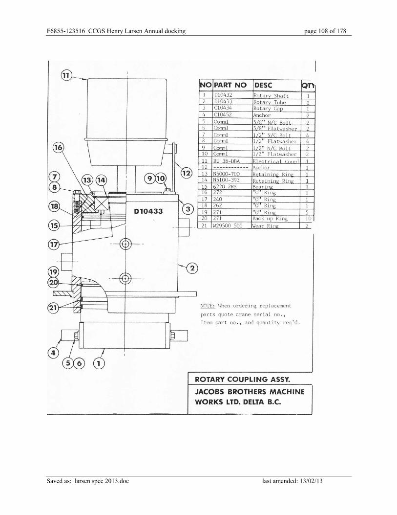
F6855-123516 CCGS Henry Larsen Annual docking page 108 of 178
Saved as: larsen spec 2013.doc last amended: 13/02/13

F6855-123516 CCGS Henry Larsen Annual docking page 109 of 178
Saved as: larsen spec 2013.doc last amended: 13/02/13
DECK CRANE CARGO BLOCKS
The intent of this specification is to perform servicing, inspection, testing, and obtain TCMS
credit for the 3 deck crane cargo blocks.
Block specifications:
Type: McKissick 341
Sheave dia: 18”
Capacity: 15 ton
1. All scaffolding, staging and rigging equipment required for removal and reinstallation of
blocks to be contractor supplied.
2. Blocks are to be removed from crane falls and transported to Contractor’s facility for
opening up and inspection of all components.
3. Blocks are to be opened up completely, all parts to be thoroughly cleaned prior to
inspection. All grease passages are to be proven clear.
4. All wearing items are to be measured and have their running clearances and
measurements recorded. A typewritten copy of the measurements and running clearances
is to be made available by the contractor to the Chief Officer during the inspection by the
Chief Officer and Transport Canada Marine Safety Inspector.
5. The measurement/running clearance readings are to clearly indicate the items and
location the readings refer to so as to allow for future referral.
6. All parts, including cheek plates, sheaves, bushings, sheave pins, swivel head fittings and
partition plates to be inspected for excess wear, fractures and distortion, by the Chief
Officer and Transport Canada Marine Safety Inspector.
7. Contractor to apply one coat of Intershield ENA 300 Bronze to a DFT of 5 mils followed
by one coat of Interguard 345 Black.
8. Defective and/or worn parts to be replaced with owner supplied parts prior to re-
assembling.

F6855-123516 CCGS Henry Larsen Annual docking page 110 of 178
Saved as: larsen spec 2013.doc last amended: 13/02/13
9. Block components to be lubricated in accordance with manufacturer’s recommendations,
and re-assembled.
10. On completion of repairs and/or inspection and subsequent approval by TCMS,
contractor to apply 2 coats owner supplied Interprime 198 Red (owner supplied) to a dry
film thickness of 2.0 mils. All coatings to be applied with strict adherence to
manufacturers’ recommended application instructions.
11. Following re-assembly, each block to be load tested by a TC Marine Safety recognized
test firm, to achieve a Safe Working Load of 10.5 tons. Test certificates for each block to
be supplied to Chief Officer on completion of tests.
12. Blocks to be reinstalled on respective cranes and tested for correct operation.
13. All work is to be completed to the satisfaction of the Chief Officer and attending TC
Marine Safety Surveyor.
F6855-123516 CCGS Henry Larsen Annual docking page 111 of 178
Saved as: larsen spec 2013.doc last amended: 13/02/13
DECK CRANE SHEAVES
1. The intent of this item is to perform servicing, inspection, testing, and obtain TCMS
credit for the 3 deck crane sheaves.
2. All scaffolding, staging and rigging equipment required for removal and reinstallation of
blocks to be contractor supplied.
3. The cable sheaves (3 per crane) are to be removed from the cranes and taken to the
Contractor’s facility for inspection by Chief Officer and Transport Canada Marine Safety
Inspector..
4. Sheaves, sheave pins and bushings to be cleaned of grease and corrosion prior to
inspection. All grease passages are to be proven clear.
5. All wearing items are to be measured and have their running clearances and
measurements recorded. A typewritten copy of the measurements and running clearances
is to be made available by the contractor to the Chief Officer during the inspection by the
Chief Officer and Transport Canada Marine Safety Inspector.
6. The measurement/running clearance readings are to clearly indicate the items and
location the readings refer to so as to allow for future referral.
7. All parts, sheaves, bushings, sheave pins, to be inspected for excess wear, fractures and
distortion, by Owner’s Representative and TC Marine Safety Inspector.
8. All sheaves are to be load tested and certificates supplied to the Chief Officer.
9. Defective and/or worn parts to be replaced with owner supplied prior to re-assembling.
10. Contractor to apply 1 coat contractor to apply 1 coat (contractor supplied) Intershield
ENA 300 Bronze to a dry film thickness of 5.0 mils to sheaves and (1) one coat of
Interguard 345 Black.
11. Components to be lubricated in accordance with manufacturer’s recommendations and
re-assembled.
12. Sheaves to be reinstalled on respective cranes and tested for correct operation.

F6855-123516 CCGS Henry Larsen Annual docking page 112 of 178
Saved as: larsen spec 2013.doc last amended: 13/02/13
13. All work is to be completed to the satisfaction of the Chief Officer and attending TC
Marine Safety Surveyor
Deck Crane Functional Test
1. The crane will be test run by the ship’s crew to test for leaks and correct operation to the
satisfaction of the Chief Engineer.
2. The Contractor is to verify the operating pressure, relief valve setting and correct safety
device operation.
DECK CRANE LOAD TEST
1. The intent of this item is to perform a load test on the three deck cranes following
completion of items:
Crane Specifications Jacobs Bros. Crane
Forward crane - well deck (SN 1140-1, 8.5 tonnes SWL/13.5 m)
Aft crane starboard side – boat deck (SN 1140-3, 10 tonnes SWL/10m)
Aft crane port side – boat deck (SN 1140-2, 10 tonnes SWL/10 m)
2. The contractor is to provide all equipment and personnel to load test the three deck cranes
to the satisfaction of the Chief Officer and attending TCMS Surveyor and provide
certificates.
3. Following all work the three deck cranes are to be load tested to the satisfaction of the
Chief Officer and attending TCMS Surveyor.
4. All weights are to be certified as to their total weight.
5. The contractor’s personnel will operate the deck cranes during the load tests.

F6855-123516 CCGS Henry Larsen Annual docking page 113 of 178
Saved as: larsen spec 2013.doc last amended: 13/02/13
6. All work is to be completed to the satisfaction of the Chief Officer and attending TC
Marine Safety Surveyor.
7. The contractor is to provide the Chief Engineer with a service report including; as found
condition, parts replaced, work performed, length and number and fittings of hydraulic
hoses, measurements, and test certificates. The report is to be typewritten and 1 hardcopy
and 1 electronic copy in pdf format provided.
F6855-123516 CCGS Henry Larsen Annual docking page 114 of 178
Saved as: larsen spec 2013.doc last amended: 13/02/13
H-05 HELICOPTER FUELING SYSTEM MAINTENANCE
Part 1: SCOPE:
1. The intent of this item is to carry out annual inspection, maintenance and certification of
the ship’s Helicopter Refueling system.
2. Contractor shall supply the services of a qualified service representative to complete the
work in this specification.
3. The Helicopter Fuel Tank Cofferdam is considered a Confined Space under the Vessel’s
Safety Management system
4. Associated Armstrong gas monitors (AMC 2011) in the following areas are to be tested
and certified in good working condition by a recognized Armstrong service
representative.
a. Pump Room
b. Cofferdam Port
c. Cofferdam Starboard
d. Emergency Resupply Hold
5. The following work shall be carried out on the Helicopter Fueling System by Contractor
certified to work on such systems:
6. Hydrostatically test fuel delivery hose.
7. Inspect hoses, fittings and nozzle.
8. Check that all pipework is properly bonded.
9. Change filters as outlined below.
10. Test remote operated quick closing valves for correct operation.
1.7 The following system valves to be removed from service for testing and certification:
1 x 1.5” vacuum relief valve (15017)
1 x 1.5” ‘UNIACT’ pressure relief valve (15009SP)
1 x 8” fire engulfment valve (6R8/411422/C)
F6855-123516 CCGS Henry Larsen Annual docking page 115 of 178
Saved as: larsen spec 2013.doc last amended: 13/02/13
11. The following system valves are to be tested in situ for correct operation and reset
following testing:
1 x 3” Quick closing fire-safe valve (main filling)
1 x 3” Quick closing fire-safe valve (main suction)
1 x 2” Quick closing fire-safe valve (sample pump suction)
12. A minimum 2.5 litre sample is to be taken from the helicopter fuel pumped from the
vessel for laboratory analysis. Laboratory testing of the fuel is to include but not
necessarily limited to:
1. Appearance / Colour
2. Water / Contaminants
3. Flash Point
4. Freezing Point
5. Distillation
6. Density
7. Copper
8. Corrosion
9. Existent of Gum
10. Water Reaction
Part 2: REFERENCES:
Guidance Drawings/Nameplate Data
1. Flow Diagram – Helicopter Fuelling Package (New-Mar Oil Services)
Standards
1. Helicopter Fuel Standard – Canada CGSB 3.23-02
Regulations
1. Transport Canada Marine Safety

F6855-123516 CCGS Henry Larsen Annual docking page 116 of 178
Saved as: larsen spec 2013.doc last amended: 13/02/13
Owner Furnished Equipment
1. As specifically noted. The contractor shall supply all materials, equipment, and parts
required to perform the specified work unless otherwise stated.
Part 3: TECHNICAL DESCRIPTION:
General
1. Helicopter fuel tank cofferdam is to be opened to allow required work. The manhole
cover is to be removed and the space certified gas free for entry. The gas free certificate
is to be maintained for the duration of necessary work. Upon completion of work the
cofferdam area is to subject to a final inspection by Owner’s representative and then
immediately closed up using new packing on the installed manhole cover. Packing
requirement as per section 3.1.4
2. Contractor shall remove identified safety valves from tank/system and transport them to a
certified testing facility. Blanks are to be fitted to exposed flanges to prevent ingress of
foreign materials into tank. Silica Gel is to be fitted to tank to absorb any moisture from
ingress of air into the tank. Removed safety valves shall be thoroughly inspected, cleaned
as necessary and certified for proper operation. Upon completion of inspection all valves
shall be boxed up, tested, reset and recertified as indicated. Contractor shall return valves
to the vessel and refit them in their original locations in good order.
3. The Contractor shall supply and install new gaskets on each of the 1.5” vacuum relief
valve and 1.5” pressure relief valve and 8” flame engulfment valve. The gasket material
used is to be intended by the manufacturer for use with Jet A helicopter fuel. The
Contractor must supply proof that the gasket material is so intended.
4. Contractor shall make arrangements to have the 1 ½:” diameter helicopter fueling hose
removed from the ship and shipped to a recognized test facility test for annual
certification, This certification will require the hose be pressure tested to 150 psi.. A

F6855-123516 CCGS Henry Larsen Annual docking page 117 of 178
Saved as: larsen spec 2013.doc last amended: 13/02/13
contractor supplied stamped metal tag showing test dates and pressures shall be affixed to
the hose. Contractor shall return the hose to the ship and re-install it on the hose reel on
the Stbd side flight deck upon completion of testing. A test certificate shall be issued to
Chief Engineer.
5. Monitor elements to be replaced. (Owner supply).
6. Filter/water Separator expendable cartridges to be replaced. (Owner supply).
7. Silica Gel in tank vent to be renewed (Owner supply).
8. Contractor to dispose of used cartridges, elements and the used Silica Gel ashore as per
Provincial regulations.
9. The original and two copies of all required inspection/test certificates for the fuel, fuel
system and components shall be given to Chief Engineer.
10. The Contractor is to provide a Service Report including the as found condition, work
performed, and any parts used in hardcopy and pdf format.
11. Upon completion of work, system is to be run up and proven fully operational to
satisfaction of the Chief Engineer or delegate.
12. Contractor to supply all materials unless specified otherwise.
Location
1. The vessel’s aviation tank cofferdam is located at the lower deck level Fr: 4 to Fr: 11 and
is accessed via the Helicopter Pump Room.
2. The control for the aviation fuel quick closing valves is located inboard of the dispensing
unit located on the Flight Deck stbd side.

F6855-123516 CCGS Henry Larsen Annual docking page 118 of 178
Saved as: larsen spec 2013.doc last amended: 13/02/13
Interferences
Contractor is responsible for the identification of interference items, their temporary removal,
storage and refitting to vessel.
Part 4: PROOF OF PERFORMANCE:
Inspection
1. All work shall be completed to the satisfaction of the Chief Engineer
Testing
Following related work, the quick closing valves are to be operated remotely to prove proper
operation. Owner’s representative to witness testing.
Certification
a. Valve Testing certification (3)
b. Fuel testing / recertification
c. Fuel hose certification
d. Gas monitor certification (4)
Part 5: DELIVERABLES:
1. Gas free certificates for subject spaces.
2. Testing reports and certificates for fuel, fuel hose, valves, gas monitors, and gauges.
3. Service Report

F6855-123516 CCGS Henry Larsen Annual docking page 119 of 178
Saved as: larsen spec 2013.doc last amended: 13/02/13
H-06 LIFERAFTS
1. The intent of this item is to transport the ship’s liferafts for annual servicing.
2. The Contractor is to remove and transport the ship's eight liferafts to and from an
authorized service centre, as designated by the vessel, for servicing.
3. The cost of servicing will be covered under Government Standing Offer issued by the
ship.
4. All work is to be to the satisfaction of the Chief Officer.

F6855-123516 CCGS Henry Larsen Annual docking page 120 of 178
Saved as: larsen spec 2013.doc last amended: 13/02/13
H-07 ACCOMMODATION HVAC CLEANING
1. The intent of this item is to clean all Supply and Re-circulating ducting associated with
HVAC systems on the Officers Deck, Boat Deck, Upper Deck and Main Deck areas.
2. The contractor shall provide the labour and materials to internally clean the ducting
associated with Air Handling Units #2 and #4, located Boat Deck, starboard side at
Frame 110.
3. The contractor shall schedule the work in a manner that will ensure minimal disruptions
to the ships personnel. The work schedule shall be agreed upon by both the Chief
Engineer and the contractor.
4. With the ship’s Electrical Officer the contractor is to ensure the Lockout/Tagout is in
place. The contractor is to supply his/her own locks and tags but complete the vessel’s
Lockout/Tagout procedure.
5. Contractor to reference, for guidance purposes, the following ship’s drawings:
Ventilation and A/C Main Deck
Ventilation and A/C Upper Deck
Ventilation and A/C Boat Deck
Ventilation and A/C Officers Deck
6. The following locations are supplied air from Air Handling Unit #2:
7. Officers’ Deck 378, 381, 381 Night Cabin, 383, 389, 389 Night Cabin, 385, and 367.
8. Boat Deck Room 339, 341, 343, 352, 350, 350 Night Cabin, and 345.
9. The following locations are supplied with air from Air Handling Unit #4:

F6855-123516 CCGS Henry Larsen Annual docking page 121 of 178
Saved as: larsen spec 2013.doc last amended: 13/02/13
Upper Deck Room 262, 260, 242, 244, 277, & 279.
Main Deck Room 130, 131, 132, & 133,Room 151, 162, 161, 160, 159, 158, & 157, 168, 167,
166, 165, 169, & 163
10. Contractor shall clean out the ducting by the application of suction at the supply and
discharge ends. Care shall be taken to minimize the ingress of dirt, dust or debris into the
spaces.
11. Access to the ducting will involve the removal of the deckhead diffusers in each space
and opening the casing at the supply fan.
12. Prior to reinstallation, all disturbed deckhead diffusers shall be washed with a degreaser.
13. Upon completion of work, all disturbed deckhead diffusers, deckhead panels, grids and
casings, shall be restored to the original as found condition.
14. Upon completion of work, the Air Handling units shall be run up and ductwork proven
free and clear.
15. The Contractor is to provide a Service Report including the as found condition, work
performed, and any parts used.
16. All work to be completed to the satisfaction of the Chief Engineer.

F6855-123516 CCGS Henry Larsen Annual docking page 122 of 178
Saved as: larsen spec 2013.doc last amended: 13/02/13
H-08 ACCOMMODATION WASHROOM EXHAUST DUCT CLEANING
1. The intent of this item is to internally clean the ductwork and fittings associated with the
Main, Upper, Boat and Officers Deck Exhaust Air systems.
2. Contractor to provide the required labor and materials to internally clean the ductwork
and fittings associated with the Upper, Boat and Officers Deck Exhaust Air systems.
3. With the ship’s Electrical Officer the contractor is to ensure the Lockout/Tagout is in
place. The contractor is to supply his/her own locks and tags but complete the vessel’s
Lockout/Tagout procedure.
4. The Contractor shall clean the ducting in a manner that will minimize the ingress of dirt
and debris into the spaces.
5. The Contractor shall schedule the work in a manner that will ensure minimal disruptions
to the ship’s personnel. The work schedule to be agreed upon by both the Contractor and
Chief Engineer.
6. Contractor to reference, for guidance purposes, the following ship’s drawings:
DWG No. 15-0311-01 Ventilation & A/C Main Deck
DWG No. 15-0311-02 Ventilation & A/C Upper Deck
DWG No. 15-0311-08 Fan Room Boat Deck Arrangement & Details
DWG No. 15-0311-03 Ventilation & A/C Boat Deck
DWG No. 15-0311-04 Ventilation & A/C Officers Deck
DWG No. 15-0401-02 I Insulation Plan, Upper, Flight/Boat, Nav Br., Raised Deck
& Wheelhouse.
DWG No. 15-0401-03 Insulation Plan Tank Top Lower & Main Decks

F6855-123516 CCGS Henry Larsen Annual docking page 123 of 178
Saved as: larsen spec 2013.doc last amended: 13/02/13
7. The Contractor to access the exhaust ductwork via deckhead mounted diffusers in the
following spaces:
Main Deck
Washrooms 138, 142, 143, 170, 171, 172, 172, 173, 174, 175, 194, 195.
200 Laundry
183 Gym, 184 Saunas Washroom
152A E/R Crew Change Room
153 Launderette
Upper Deck
Washroom 265, 267, 269, 252, 271, 275, 294, 292, 257, 288, 251, 286, 284 and 282.
Boat Deck
Washroom 339, 334, 341, 343, 352, 350, 347, 345, and SAR Locker.
Officers Deck
Washroom 378, 381, 383, 389, 385, 374, 365, and 367
Wheelhouse
Washroom adjacent to Wheelhouse Stair tower entrance.
Upon completion of the work, any deckhead accessories disturbed by the Contractor during the
cleaning operation, to be restored to their as found condition.
8. Upon completion of work, the Washroom Exhaust Fan shall be run up and ductwork
proven free and clear.
9. The Contractor is to provide a Service Report including the as found condition, work
performed, and any parts used.
10. All work to be completed to the satisfaction of the Chief Engineer.

F6855-123516 CCGS Henry Larsen Annual docking page 124 of 178
Saved as: larsen spec 2013.doc last amended: 13/02/13
H-09 GALLEY RANGE HOOD AND EXHAUST FAN TRUNKING
1. The intent of this item is to open up, clean and close up in good order the Galley range
hood and exhaust fan trunking.
2. Galley Range Hood (Gaylord model BDL-DS) shall be opened up for thorough cleaning
and degreasing. The existing exhaust fan trunking run from the Galley Range hood to the
Exhaust fan outlet at Upper Deck, port side Frame 30, shall be internally degreased and
cleaned.
3. The contractor shall co-ordinate the work with the Chief Engineer to minimize
disruptions to ship’s routine. Contractor to include in bid, his and any sub-contractor’s
cost for premium time for evenings, weekends and/or holidays worked.
4. With the ship’s Electrical Officer the contractor is to ensure the Lockout/Tagout is in
place. The contractor is to supply his/her own locks and tags but complete the vessel’s
Lockout/Tagout procedure.
5. All chemicals used in cleaning the range hood and galley exhaust fan trunking shall be
non-toxic and safe for use in food preparation and handling areas. Contractor to provide 2
copies of product Material Safety data Sheet information corresponding to the cleaning
agents which will be used in the cleaning process.
6. Prior to the commencement of work, qualified personnel shall release all range hood
mechanical and electrical components, including suppression system piping, controls and
lighting. All fittings liable to interfere with cleaning of the range hood are to be
temporarily relocated and protected.

F6855-123516 CCGS Henry Larsen Annual docking page 125 of 178
Saved as: larsen spec 2013.doc last amended: 13/02/13
7. The range hood filter screens to be removed and steam cleaned. All range hood drains
and grease traps shall be proven clear. Fire dampers to be cleaned and demonstrated in
good working order.
8. The contractor shall remove all debris and soiled materials from the vessel and disposed
of ashore daily
9. Upon completion of work, the contractor shall return all disturbed range hood
components as per original. Range hood wash-down system shall be tested and proven
operational.
10. The contractor shall access the exhaust trunking by removing the following:
11. in deck cross alleyway and Galley ceiling panels in way of the trunking run.
12. Main deck flanged exhaust trunking fire damper. Unit flanged and bolted in situ.
13. Inline exhaust fan, located Upper Deck Fan Room. Unit flanged and bolted in situ.
14. Two- 12”x12” sheet metal trunking access panels Upper Deck fan room. Screwed in situ.
15. Port side Upper Deck exhaust trunking outlet louver. Bolted in situ.
16. The Galley Exhaust Fan to be removed to allow for cleaning of trunking on either Side.
Fan and motor units to be completely degreased.
17. The exhaust trunking outlet louver shall be removed. Fine mesh screen to be removed
and cleaned. Remainder of louver, including cover, to be sandblasted to white metal and
painted with two coats of primer and one coat of white paint. Hinge pins to be freed up
and greased. Louver door rubber seal to be removed during sandblasting and painting,
then reinstalled with proper adhesive. New gasket to be supplied when louver bolted in
place.
18. All disturbed exhaust trunking access points shall be reinstalled using fire rated materials.

F6855-123516 CCGS Henry Larsen Annual docking page 126 of 178
Saved as: larsen spec 2013.doc last amended: 13/02/13
19. Prior to reinstallation of the main deck ceiling panels, the fire damper shall be tested to
the satisfaction of the Chief Engineer for correct operation.
20. The Contractor is to provide a Service Report including the as found condition, work
performed, and any parts used. The service report is to be provided in Adobe pdf format.
21. All work is to be completed to the satisfaction of the Chief Engineer.
F6855-123516 CCGS Henry Larsen Annual docking page 127 of 178
Saved as: larsen spec 2013.doc last amended: 13/02/13
H-10 ASBESTOS REMEDIATION
Part 1: SCOPE:
The intent is to: Following Type 2 asbestos abatement procedures clean areas identified in
moderate and excessive condition as outlined by the survey of any loose debris that has fallen
down off the deckhead only in the areas noted.
This work shall be carried out in Conjunction with the following:
Part 2: REFERENCES:
Guidance Drawings/Nameplate Data
‘Asbestos Containing Materials Reassessment Survey 2012’
Regulations
The following regulations shall be used in carrying out this work. Current edition of documents,
at time of contract implementation, shall be used.
TCMSB Hull Construction Regulations and Part X “Fire Protection for Cargo Ships of 500 Tons
Gross Tonnage or More”, Method 1C and TP 127E for electrical system modifications. Current
edition of documents at time of contract implementation shall be used.
Newfoundland and Labrador Regulations, 111/98, Asbestos Abatement Regulations 1998, under
the Occupational Health and Safety Act (O.C. 98-730).
Canadian Coast Guard Fleet Safety and Security Manual
Owner Furnished Equipment
1. The contractor shall supply all materials, equipment, and parts required to perform the
specified work unless otherwise stated.

F6855-123516 CCGS Henry Larsen Annual docking page 128 of 178
Saved as: larsen spec 2013.doc last amended: 13/02/13
Part 3: TECHNICAL DESCRIPTION:
General
1. All materials are to be Contractor supplied.
2. Ensure Asbestos Work Record and Work Permit is complete.
3. Remove deckhead panels as appropriate in the affected spaces to gain access to the areas
to be worked on.
4. Perform cleanup of loose debris from above the deckhead panels in the spaces noted in
the list.
5. Each area will be inspected by the Chief Engineer before the deckhead panels are
replaced.
6. Repair or replace expanded metal mesh as noted in the list.
7. All debris and ACM is to be removed from the vessel and properly disposed of as per
applicable Provincial regulations.
8. Excerpts from the shipboard survey table are below. A more detail survey will follow in
the form of a Report from Pinchin Leblanc.
9. Locations
Hallway outside cabin 244 Moderate-excessive Upper deck Fan room 222 Upper Deck Perforated metal damage along deck
Salvage/Diving (271) Upper Deck Needs repair under door and elect panel Motor room flat escape hatch Repair metal Prop Motor Rm, Port & Stbd and Needs repair, some big chunks Aft corner near shaft. Tank top Logistics Officer’s Office Moderate-excessive
Laundry -Main Deck Moderate to excessive still present
F6855-123516 CCGS Henry Larsen Annual docking page 129 of 178
Saved as: larsen spec 2013.doc last amended: 13/02/13
Interferences
1. Contractor is responsible for the identification of interference items, their temporary
removal, storage and refitting to vessel.
Part 4: PROOF OF PERFORMANCE:
1. All work shall be completed to the satisfaction of the Chief Engineer.
2. Testing
3. The Contractor shall perform tests to verify that all requirements of the Specification are
met.
4. The Contractor shall provide a set of detailed instructions providing a tests and trials
agenda including expected results for verification of all system changes.
5. As a minimum, the Contractor shall provide:
6. Air quality testing as per requirements under Asbestos Abatement.
7. Instruments and services for testing and trials; instruments shall be in calibration.
8. Certification
9. The Contractor shall obtain and provide to the Technical Authority all required technical
Certifications as specified. These shall include but not be limited to the following:
10. Material test certificates including all test reports supporting the certifications.
11. Asbestos Abatement Certificates.
Part 5: DELIVERABLES:
1. The contractor shall update the Vessel’s Asbestos Containing Materials Reassessment
Plan to reflect removals performed during the refit period.

F6855-123516 CCGS Henry Larsen Annual docking page 130 of 178
Saved as: larsen spec 2013.doc last amended: 13/02/13
H-11 LAUNDRY DRYER EXHAUST DUCTWORK CLEANING
2. The intent of this item is to clean the clothes dryer(s) exhaust ductwork on the Officers
Deck, Boat Deck, Upper Deck and Main Deck to remove any accumulation of lint and or
debris.
3. The contractor shall schedule the work in a manner that will ensure minimal disruptions
to the ships personnel. Both the Chief Engineer and the contractor shall agree upon the
work schedule.
4. The Contractor in consultation with the vessel’s Electrical Officer will lockout the power
supply(s) to the dryers.
5. The Contractor is to supply their own locks and tags and complete the vessel’s
Lockout/tagout procedure.
6. The contractor shall provide the labor and materials to internally clean the dryer exhaust
ducting associated with the as fitted laundry dryers in the following spaces:
Main Deck Laundry Room, Main Deck Room 200, at Fr.167
Main Deck Launderette, Main Deck, Room 153, at Fr.116
Oilers Change room, Main Deck, Room 152 at Fr. 16
Upper Deck Launderette, Upper Deck Room 252, at Fr.122
Boat Deck launderette, Boat Deck, Room 334, at Fr.122
Officers Deck Launderette, Officers Deck Room 365, at Fr.112
The dryer exhaust ducting is to be cleaned from the dryer to the vent head on the
vessel’s exterior.
7. The Contractor shall clean out the dryer exhaust ducting by the application of suction at
the supply and discharge ends. Care shall be taken to minimize the ingress of dirt, dust or
debris into the spaces. Any ingress of dirt, dust or debris is to be cleaned up.
8. Any openings made in the ductwork are to be sealed using approved seals such that there
are no leaks at the openings.

F6855-123516 CCGS Henry Larsen Annual docking page 131 of 178
Saved as: larsen spec 2013.doc last amended: 13/02/13
9. Upon completion of work, all disturbed ducting and associated fittings shall be restored
to their as found condition.
10. The Chief Engineer will inspect disturbed ductwork before ceiling panels are reinstalled.
11. Upon completion of work, the dryers shall be run up and ductwork proven free and clear.
12. The Contractor is to provide a written report in electronic pdf format to the Chief
Engineer detailing the as found condition, work performed, and digital images showing
the before and after condition of the ducting.
F6855-123516 CCGS Henry Larsen Annual docking page 132 of 178
Saved as: larsen spec 2013.doc last amended: 13/02/13
H-12 SEWAGE SYSTEM Part 1: SCOPE: 1.1 The intent of this specification shall be to clean, inspect, coat as necessary and return the
sewage system treatment tank to service. 1.2 This work shall be carried out in Conjunction with the following: Part 2: REFERENCES: 2.1 Guidance Drawings/Nameplate Data
RED FOX Industries Inc.
Model : PVCL-6R
Location: Auxiliary Machinery Space - Fr. 65 - 75.
Holding capacity : 19,000 litres.
Description: Segregated tank measures 2.1m x 4.2m x 2.4 m which is divided
into three compartments; aeration, clarifier and disinfection chambers.
2.1.1. 2.2 Standards
2.2.1 The sewage system treatment tank is considered a confined space under the Safety Management System.
2.3 Regulations
2.3.1
2.4 Owner Furnished Equipment
2.4.1 The contractor shall supply all materials, equipment, and parts required to
perform the specified work unless otherwise stated. Part 3: TECHNICAL DESCRIPTION: General
3.1 The intent is to keep the vessel’s sewage system in use during this item using the sewage discharge line indicated in HD-05 Services.

F6855-123516 CCGS Henry Larsen Annual docking page 133 of 178
Saved as: larsen spec 2013.doc last amended: 13/02/13
3.2 The tank is to be serviced as required and removed upon completion of this item. 3.3 The daily cost and servicing cost is to be quoted. 3.4 All effluent is to be disposed of by the Contractor. 3.5 Disposal certificates to be provided to PWGSC. 3.6 The contractor shall pump out the sewage treatment plant and dispose of contents
ashore. The effluent, sludge and any solid wastes are to be disposed of in accordance with local environmental regulations.
3.7 With the ship’s Electrical Officer the contractor is to ensure the Lockout/Tagout is
in place. The contractor is to supply his/her own locks and tags but complete the vessel’s Lockout/Tagout procedure.
3.8 Manhole covers to be removed to gain access to tank internals. 3.9 Ventilation to be provided from the sewage tank to an open deck and over the side
of the vessel for the entire period the sewage tank is opened. 3.10 Prior to the commencement of cleaning, all tanks are to be certified gas free for
worker entry by a marine chemist and certificates posted in conspicuous locations as required by the CLC. All Contractor workers entering any tanks are to be qualified as per CLC.
3.11 Tank internals to be pressure washed clean. All water remaining in tank after
cleaning is to be pumped out and disposed of ashore by Contractor. 3.12 The tank internals including all piping and air manifolds are to be cleaned of all
traces of effluent and liquid using a detergent and sanitized using disinfectant. MSDS for the cleaning and sanitizing chemicals to be provided to Chief Engineer before cleaning begins.
3.13 Cleanout plugs in the manifolds are to be removed and manifolds cleaned of any
debris. Cleanout plugs to be reinstalled following inspection by the Chief Engineer.
3.14 All liquid remaining in tank after cleaning is to be pumped out and disposed of
ashore by Contractor. 3.15 Tank to be rag wiped dry after cleaning. 3.16 Internals then to be cleaned to prepare surfaces for coating. Power tool cleaning
to be to standard SSPC-SP-3.

F6855-123516 CCGS Henry Larsen Annual docking page 134 of 178
Saved as: larsen spec 2013.doc last amended: 13/02/13
3.17 All dirt and debris remaining in tanks after cleaning shall be removed ashore and
disposed of by the Contractor 3.18 Contractor to supply any ventilation equipment required for the gas free
Certificate and the certificate’s continued validity for the duration of the work. Contractor also to supply ventilation as required during the cleaning and coating of tank internals.
3.19 All associated air piping on the tank top as well as all internal passages, orifices
and piping are to be proven clear. Switch column to be disconnected from its piping, inlet and outlet openings and internals column to be thoroughly cleaned and reconnected.
3.20 After completion of thorough cleaning, bare metal surfaces to be primed. Tank
internals are then to be given one coat of coal tar epoxy – bid on 40 m2. The level switches, probes and orifices are to be protected during painting to ensure operational integrity.
3.21 Upon completion, all level switches, probes and alarms shall be cleaned,
inspected and function tested. 3.22 After sufficient time for coating to cure has passed, the contractor is to install the
manhole covers using new contractor supplied gaskets and the tanks are to be refilled to the operating level with clean fresh water.
3.23 All work is to the satisfaction of the Chief Engineer.

F6855-123516 CCGS Henry Larsen Annual docking page 135 of 178
Saved as: larsen spec 2013.doc last amended: 13/02/13
H-13 HULL, VOID SPACE & TANK SURVEY Part 1: SCOPE: The intent of this specification item shall be for the contractor to provide access to various parts of the hull and internal tanks to allow a vessel hull condition survey. The work will involve the opening-up of void spaces, fuel and water ballast tanks and the provision of scaffolding or certified man-lift for the inspection of the exterior hull and for taking of Ultrasonic Thickness (UT) measurements. The location of the UT measurements will be determined by a Classification Society arranged using separate contract by the Technical Authority. Part 2: REFERENCES: Requirements directed by the Classification Society Inspector. Part 3: TECHNICAL DESCRIPTION: Hull Structure: 3.1 The contractor shall provide the services a firm specializing in NDT (ultrasonic thickness
testing) to determine the shell plating thickness as indicated by the Classification Society. The Contractor shall bid on 1000 shots (including proper surface preparation), with a unit cost for each additional shot which includes travel expenses from the NDT testing company. This cost will be adjusted by PWGSC 1379 action.
3.2 The contractor shall provide any staging or certified man-lifts required to enable the
Classification Society to perform a detailed examination and inspection of the hull and for the ultrasonic thickness testing. The contractor shall quote on the provision of a certified man-lift including operator for a period of 100 hours and provide unit cost per hour for the use of the man-lift and operator. This cost will be adjusted by PWGSC 1379 action.
3.3 The Classification Society Inspector will direct where the UT shots and inspection will take
place.

F6855-123516 CCGS Henry Larsen Annual docking page 136 of 178
Saved as: larsen spec 2013.doc last amended: 13/02/13
3.4 At a minimum these will be:
Side shell and steel abutting side shell where abrasion/damage is considered likely due to ice interaction.
Wind and water strakes of the side shell (ice belt) Bottom shell plating Bow area Forefoot /ice skeg area Areas with step changes in hull modulus, or in areas experiencing high sheer due to
icebreaking. Accommodation block deck connection Area above the forefoot /ice skeg
Voids and Ballast Tanks: VOID Spaces – ( Already identified for opening, cleaning and survey in spec #HD-13 Void
Spaces)
Name Location Capacity M3 Field No
No 1 Void WB Tank Stbd Fr 18-30 105.94 m3 3L004
No 1 Void WB Tank Port Fr 18-30 105.36 m3 3L005
Cofferdam (aft) Fr 13-30 92.07 3L010
No 2 Void Stbd Fr 127-140 29.54 m3 3L036
No 2 Void Port Fr 127-140 29.54 m3 3L037
No 3 Void Stbd Fr 140-150 17.25 m3 3L038
No 3 Void Port Fr 140-450 17.25 m3 3L039
**No 4 Wing Void Tank Stbd Fr 150-165 92.019 m3 3L043
**No 4 Wing Void Tank Port Fr 150-165 92.019 m3 3L044
Cofferdam Fr120-127 19.0 m3 3L035
Pipe Tunnel Fr 122-167 3L042
Manhole Locations
No 1 Void WB Tank Stbd Prop Mtr Room aft bulkhead.
No 1 Void WB Tank Port Prop Mtr Room aft bulkhead.
Cofferdam (aft) Prop Mtr Room aft bulkhead

F6855-123516 CCGS Henry Larsen Annual docking page 137 of 178
Saved as: larsen spec 2013.doc last amended: 13/02/13
No 2 Void Stbd Pipe Tunnel
No 2 Void Port Pipe Tunnel
No 3 Void Stbd Pipe Tunnel
No 3 Void Port Pipe Tunnel
No 4 Wing Void Tank Stbd Lower Bubbler Compt.
No 4 Wing Void Tank Port Lower Bubbler Compt.
Cofferdam Eng Room fwd.
Pipe Tunnel Eng Room fwd.
Ballast Tanks – (Already identified for opening, cleaning and survey as part of spec item HD-16
– Ballast Tanks)
Tank Location Capacity Field
(Frame #) (M3) No.
Aft Peak Stern – 0 82.80 3L001
Aft Trim 0 – 18 109.90 3L003
Aft Stability 127 – 140 197.76 3L040
Fwd Stability 140 - 150 256.05 3L041
M/E Jacket Water 118.5 – 125 7.53 3L034
Fuel Tanks. Fuel tanks – (Already identified for opening and survey as part of spec item HD-17 – Fuel tanks. Name Location Capacity TCMS
(Frame) (m3) Field No
No 3 FO DB Tank Stbd 30-61 82.64 3L013
No 3 FO DB Tank Port 30-61 81.27 3L014
No 4 FO DB Tank Stbd 61-83 67.02 3L015
No 4 FO DB Tank Port 61-83 59.73 3L016

F6855-123516 CCGS Henry Larsen Annual docking page 138 of 178
Saved as: larsen spec 2013.doc last amended: 13/02/13
No 6 FO DB Tank Stbd 89-120 93.54 3L027
No 6 FO DB Tank Port 89-120 93.54 3L028
Oily Bilge Retention Tank 61-67 5.7 3L020
Waste Oil Tank 67-71 3.44 3L021
FO Overflow Tank 122-127 7.37 3L031
Dirty LO Tank 122-127 4.94 3L033
Settling Tank 127-150 175.66 3L055
FO Drain Tk (Stbd) 121-127 3L032
Part 4: PROOF OF PERFORMANCE:
4.1 The Contractor is to be responsible for all inspections and UT shots required by
the Classification Society Inspector to determine an inspection schedule; at each inspection point, the Contractor is to advise the Owner’s representative, in advance, to allow his/her attendance.
Part 5: DELIVERABLES:
5.1 Upon completion of all UT and inspection points, the Contractor and the Owner’s representative (or designate) shall conduct a final inspection and ensure all tanks, covers, have been returned to operating conditions and the attending Classification Society Inspector has completed all inspections.

F6855-123516 CCGS Henry Larsen Annual docking page 139 of 178
Saved as: larsen spec 2013.doc last amended: 13/02/13
ED-01 TAILSHAFT WEARDOWN
1. The intent of this item is to take both tailshaft bearing clearances at the stern tube rope
guards
2. The contractor is to take and record within eight hours of docking the ship the wear-down
of the port and starboard tailshaft bearings with feeler gauges.
3. The port and stbd rope guards are to be removed in half sections and lowered to the dock
bottom.
4. Upon completion and in conjunction with items the rope guards are to be reinstalled in
good order.
5. A typewritten copy of the readings obtained is to be passed to the Chief Engineer within
2 calendar days of being taken.
6. All work is to be completed to the satisfaction of the Chief Engineer.

F6855-123516 CCGS Henry Larsen Annual docking page 140 of 178
Saved as: larsen spec 2013.doc last amended: 13/02/13
ED-02 PORT TAILSHAFT
The intent of this item is to remove the port tailshaft for survey and TCMS credits and reinstall in
good order
The following components are involved:
Coupling = 3,252 kg;
Propeller = 14, 870 kg;
Tailshaft = 41,829 kg, 15.2 meters long;
Intermediate Shaft = 3,995 kg, 2 meters long.
1. All removals/disconnections and reinstallations/connections, mechanical and electrical, to
be included in price.
2. Due to the easily damaged nature of the tailshaft coating between liners, it is necessary to
take special precautions during the removal and installation of the tailshaft to avoid
contact between the coating and the ship's structure or lifting devices.
3. Whether supported on skids or slings, the weight of the tailshaft has to be carried in way
of the bronze bearing surfaces only. Soft fabric slings or soft wood blocks are to be used.
4. A special skid is required to support the forward end of the shaft, and an end support
piece with roller is bolted to the forward end of the tailshaft. Hardwood blocks,
contractor supplied, are also required during removal operations to protect the shaft
bearing staves.
5. Note: A tailshaft extension cone has been fabricated to facilitate the removal and
installation process. The contractor shall check this extension piece and be responsible
for its safe usage and transportation from the Boat Deck to and from the Motor Room.
(see attached sketches).
F6855-123516 CCGS Henry Larsen Annual docking page 141 of 178
Saved as: larsen spec 2013.doc last amended: 13/02/13
6. If the tailshaft needs to be turned over during this time, the contractor is to inform the
Chief Engineer so that the lubricating water can be turned on. Turning gear to be
operated by ship's staff only.
7. Contractor is to note that the tailshaft cannot be removed from the sterntube using the
lifting lugs on the ship. Separate lifting and support equipment is required.
8. It will be necessary to remove a section of an 8" support stanchion in way of the tailshaft
coupling. While removed, the piece is to be made removable by welding flanges on each
end of the removed section and also on the stanchions on the ship’s structure, such that
the section of stanchion can be bolted back in place. The removed section of stanchion is
to be reinstalled after all work on the tailshaft/coupling using new contractor supplied
grade 8 hex head capscrews c/w flat washers, lock washers and hex head nuts.
9. Any hull mounted lifting lugs required for removals are to be provided and installed by
contractor. The contractor is responsible for testing and certification of such lugs. Upon
completion of work lugs are to be cut off, ground flush, and coated as per Specification
Item HD 13- Hull Coating.
10. Contractor to note that no high voltage cable supports or high voltage cables are to be let
go, moved, etc., until the Chief Engineer has concurred. Also, Contractor to ensure that
no chain falls, slings, etc., bear against cables or piping in the area during lifting, moving
or support operations.
11. Weardown readings are to be taken on inside of sterntube after mechanical seal is
removed and before tailshaft is uncoupled. Readings to be given to Chief Engineer.
12. Recommended Withdrawal Procedure:
13. Complete area forward of the forward sterntube bush is to be thoroughly scraped and
wire brushed clean for application of Belzona metal compound. All holes and pitted

F6855-123516 CCGS Henry Larsen Annual docking page 142 of 178
Saved as: larsen spec 2013.doc last amended: 13/02/13
areas to be properly prepared and filled with Belzona metal compound as per
manufacturer's instructions. Surface preparation is to be to Power Tool Clean Standard
SSPC-SP11.
14. After metal compound has completely cured, the Contractor is to apply two (2)coats of
Interguard ENA 377, as per manufacturer's instructions - minimum thickness per coat = 6
mils dry.
15. Remove rope guard, propeller cone, and propeller. The propeller removal and fitting gear
may be supplied by the Canadian Coast Guard and consists of hydraulic pump and
fittings, pilgrim nut, special backing plate and other removal tools. Contractor shall be
responsible for moving all tools from the ship to the drydock and returning and securing
tools back on the ship after the work is completed. Propeller is removed with pilgrim nut,
special backing plate, and ship supplied removal tools. All work is to be to as per
manufacturer's instructions. Contractor is to note that lifting eyes in propeller bossing are
for vertical lifts only and must not be used for pulls in any other directions. Any turning
of the shaft required during this work is to be done by ship's personnel. Contractor to
supply lubricating water for shaft if required.
16. Remove intermediate shaft/coupling bolts and motor/intermediate shaft bolts, supporting
weight of intermediate shaft with slings. Morgrip bolts to be removed as per
manufacture's instructions with removal gear that may be supplied by the ship. Morgrip
bolts are to be marked and reinstalled in their original holes. Shaft brake disc to be
unbolted and stowed if required. Morgrip bolts to be identified and put in a lathe and
checked for trueness and bolt diameters measured. Both intermediate shaft flange face
bolt holes to be checked for roundness and readings recorded. One typewritten copy of
all readings to be given to Chief Engineer. Bolts are to be stowed in a traffic-free area.
17. NOTE: Shaft brake chock fast to be renewed when brake reinstalled and proper alignment
of brake maintained.

F6855-123516 CCGS Henry Larsen Annual docking page 143 of 178
Saved as: larsen spec 2013.doc last amended: 13/02/13
18. Withdraw tailshaft outboard sufficiently to install first lifting clamp on aft end of aft
liner. Move intermediate shaft, complete with turning gear ring, to one side and secure.
Turning gear unit may be unbolted at this time if required.
19. Coupling to be removed with Pilgrim nut and ship supplied tools. Chief Engineer to be
in attendance at this time. It will be necessary to heat the coupling during removal
operations. Coupling shall be heated from outside diameter; inside bore of coupling
temperature range 144ºC to 196ºC maximum by electric heating blanket (Contractor
Supply). Contractor to ensure this heating procedure does not damage or endanger any
surrounding equipment or personnel. Flame heat is not to be used.
20. NOTE: Maximum pressure to pump off nut = 1380 kg/cm² (2000 psi), this pressure is
NOT to be exceeded.
21. Install skid support. Withdraw tailshaft outboard until coupling taper is over forward end
of skid and install end support piece on shaft. ( to trial the new extension support cone
(see attached sketches ).
22. Roller on shaft support piece to be adjusted to allow roller to roll on forward bush staves.
23. NOTE: Hydraulic jack should be used to support forward end of shaft when adjusting
height of roller. ( roller will not be required if support cone is used).
24. Withdraw tailshaft until forward end of coupling taper is at bulkhead 34. Install second
lifting clamp on forward end of aft liner.
25. Remove tailshaft aft until shaft support piece is at the end of the forward bush. Install
shaped hardwood blocks (Contractor supplied) on bottom radius of sterntube to allow
tailshaft to continue to move out on roller. Alternate blocks as required.

F6855-123516 CCGS Henry Larsen Annual docking page 144 of 178
Saved as: larsen spec 2013.doc last amended: 13/02/13
26. During this stage, the aft liner will clear the aft bearing. Special care must be taken to
maintain the shaft alignment to prevent damage to the shaft coating between the liners.
27. Withdraw tailshaft until it is clear of forward bearing. Check alignment to ensure the
forward liner will enter the after bearing and continue to withdraw. When the end
support piece is at the forward end of the aft liner, check alignment and move carefully
onto aft bearing surface. Continue to withdraw until approximately one meter of forward
liner is clear of aft bearing and install third lifting clamp on forward liner. The weight
and alignment of the tailshaft should now be controlled by the shipyard lifting gear. The
tailshaft is now completely withdrawn.
28. Tailshaft to be stowed in a suitable Contractor supplied cradle to allow for inspection by
TCMS. Cradle supports on shaft to be in way of bronze liners only. If sandblasting or
any other potentially damaging work is being done in the vicinity of the withdrawn
tailshaft, Contractor to supply and install protective covering over shaft.
29. Contractor to supply and schedule a certified technician to perform non-destructive
testing on the following:
a. Propeller key.
b. Shaft and propeller keyways.
c. Interior propeller taper.
d. Forward and aft tailshaft shaft tapers.
30. Key and keyways to be measured with micrometers, measurements recorded and
clearances shown.
31. Weardown readings, measured with inside and outside micrometers, to be taken between
fwd and aft sterntube bearings and bronze liners on tailshaft and recorded. Three copies
of the NDT test reports and micrometer readings shall to be given to the Chief Engineer
within 2 calendar days of the testing.
F6855-123516 CCGS Henry Larsen Annual docking page 145 of 178
Saved as: larsen spec 2013.doc last amended: 13/02/13
32. While the tailshaft is removed the stern tube internals are to be inspected for defects.
Particular attention is to be paid to inspecting the stern tube for'd end immediately aft of
the seal. All sterntube and sterntube seal lubrication/cooling lines are to be proven clear
and free from any obstructions.
33. Complete area in the stern tube between the forward and aft bushings (approximately 5m
long x .75m dia.)to be thoroughly scraped and wire brushed clean to meet paint
manufacturer's specifications. All debris to be completely removed ashore. All holes and
pitted areas deeper than three millimeters (3mm) are to be properly prepared and filled
with Belzona metal compound as per manufacturer's instructions. Surface preparation is
to be to Power Tool Clean Standard SSPC-SP11.
34. After metal compound has completely cured, Contractor to apply two (2) coats of
Intershield ENA 300, as per manufacturer's instructions - minimum thickness per coat = 6
mils dry.
35. All areas in sterntube fwd. flange face where metal has wasted to be cleaned as described
above and filled with metal using approved electric arc welding procedures. Contractor to
supply a copy of welding procedure used to Chief Engineer. Upon completion sterntube
flange face to be ground smooth and level to accept new bulkhead gasket and to ensure
no leaks exist between sterntube seal flange and bulkhead when the ship is re-floated.
36. Intershield ENA300 is to be applied to stern tube flange face and corresponding bulkhead
area as per manufacturer's recommendations in two coats (minimum thickness per
coating is 6 mils dry).
37. Mechanical means of ventilation shall be provided for complete drying of the paint
before reinstallation of the tailshaft.

F6855-123516 CCGS Henry Larsen Annual docking page 146 of 178
Saved as: larsen spec 2013.doc last amended: 13/02/13
38. Contractor to supply and schedule the services of a certified technician to perform a spark
test on the coated sections of tailshaft with TCMS inspector and Chief Engineer in
attendance.
39. Should it be required to replace the existing tailshaft coating, as determined by spark test,
Bidder to quote separately for this work, as specified under the following;
a) Existing coating to be removed in its entirety with tailshaft in support cradle.
b) Before any sandblasting to bring coated area to bare steel, ensure the following areas
are protected: Port tailshaft stern tube opening to be completely sealed, bronze liners
wrapped on Port shaft, and Port stern tube sealed in way of outer seal.
c) Sandblast steel between liners to quality recommended by tailshaft coating
manufacturer, see attached information sheets.
d) The contractor is then to build a structure over the tailshaft such that the temperature
and humidity within can be controlled and such that the temperature of the shaft can
be brought up to that required for the application of the new protective coating.
e) New semi-transparent, glass-reinforced, epoxy-laminated shaft wrapping,
Philadelphia Resins Phillyclad 1775/620TS, is to be supplied and applied in way of
the previously covered areas.
f) New shaft wrapping to be applied according to Manufacturer's instructions under the
direction of an authorized Service Representative, services who is the responsibility
of the contractor. Allow $10,000.00 for FSR expenses, to be adjusted by 1379 action
upon proof of invoices.
g) Allow sufficient time for coating to cure before installing shaft. It is important to
ensure the integrity of the coating between the liner/shaft interface to prevent the
ingress of sea water under the bronze liners.
40. Inspection on the tailshaft will be carried out by the contractor and witnessed by the
Chief Engineer and TC Marine safety with particular attention being paid to the
following areas:
41. Forward and aft keys and keyways on the shaft tapers
42. Forward and aft shaft tapers
F6855-123516 CCGS Henry Larsen Annual docking page 147 of 178
Saved as: larsen spec 2013.doc last amended: 13/02/13
43. The forward and aft ends of the aft liner where it meets the tailshaft.
44. The forward and aft ends of the forward liner where it meets the tailshaft.
45. Forward and aft "Pilgrim" nut threads
46. Fwd and aft liners in way of bearing surfaces.
47. Fwd liner in way of the crane seal & liner extension.
48. A certified NDT Technician is to perform non-destructive testing of propeller and shaft
taper key and keyways in No. 1 & 2 above. Three copies of the test reports are to be
given to the Chief Engineer within 2 calendar days of the testing.
.
Shaft Installation Procedure:
1. NOTE: Forward and aft bearing staves are to be lubricated with liquid soap,
Contractor supplied, sufficient to provide lubrication during shaft installation but not
block water cooling passages. All tailshaft bearing surfaces are to be wiped
completely clean of any dirt, sand, etc., before tailshaft is installed. No sand or grit
blasting to be carried out until tailshaft installation is complete.
2. Reverse procedure to be used to install shaft. Care to be exercised to ensure shaft is
correctly aligned with sterntube and epoxy liner and staves are not damaged during
installation.
3. Taper end of tailshaft and coupling bore to be thoroughly cleaned and degreased
using electrolytic cleaner. Key to be installed and proven true.
4. Coupling to be heated from outside diameter by electric heating blanket (Contractor
Supply). Inside bore of coupling to be heated to 144ºC to 196ºC maximum.

F6855-123516 CCGS Henry Larsen Annual docking page 148 of 178
Saved as: larsen spec 2013.doc last amended: 13/02/13
5. NOTE: Heat blanket shall be left on during push up. Contractor to ensure this
heating procedure does not damage or endanger any surrounding equipment or
personnel. Ensure tire on Pilgrim nut has been fully compressed.
6. Coupling to be located over tailshaft and moved up the taper using the Pilgrim nut to
the datum mark - maximum travel is 4mm, minimum is 3.8mm. Contractor to take
care clearance is maintained on either side of keyway.
7. With pressure left on Pilgrim nut, allow coupling to cool to ambient temperature.
Check and record keyway clearances. Secure Pilgrim nut as per manufacturer's
instructions.
8. Install shaft disc brake ring at this point. Intermediate shaft to be installed and bolted
to propulsion motor. If turning gear unit was removed, Contractor to reinstall using
new chockfast and taking care to correctly alignment of the gearing.
9. Final alignment check and bolting up of intermediate shaft to coupling flange not to
be completed until the ship has been afloat for a minimum of 24 hours.
10. Original propeller to be installed as per manufacturer’s instructions.
11. Contractor to supply and install 2 new propeller 'O'-rings. 'O'-ring material to be
21mm DIA. nitrile rubber (hardness of 55/60). Shaft diameter in 'O'-ring location is
approximately 754mm.
12. The propeller removal and fitting gear, which may be supplied by the Canadian Coast
Guard consists of hydraulic pump and fittings, pilgrim nut, special backing plate and
other removal tools. Contractor responsible for moving all tools from the ship to the
drydock and returning and securing tools back on the ship after the work is
completed.

F6855-123516 CCGS Henry Larsen Annual docking page 149 of 178
Saved as: larsen spec 2013.doc last amended: 13/02/13
13. Contractor to fit propeller to tailshaft. Contractor to quote on two fits plus price per
fit for adjustment purposes. Final fit, witnessed by TCMS and Chief Engineer, to
have minimum 90% light blue covering.
14. For all fits except the last fit, propeller to be pushed up a maximum of 2mm travel.
Start point load pressure on the hydraulic pump to measure the push up distance is
220 kN. Final push up distance and pressure to be as per ship supplied push up
diagram.
15. After final fit, witnessed and approved by Chief Engineer, the propeller and tailshaft
mating surfaces to be thoroughly degreased, tailshaft threads liberally coated with
anti-seize compound and propellers pushed up on shafts with pilgrim nuts to required
distance, as per Pilgrim Moorside recommendations. Final push up distances,
pressures and key clearances (top & sides) to be recorded and given to Chief Engineer
in three type written copies.
16. Pilgrim nut to be locked in place and grease pumped in circumferential grease
fittings. Propeller cone to be installed and filled with tallow. Bolt holes to be
cemented after bolts secured.
17. All welded lugs are to be removed and welding ground flush. Areas to be painted in
conjunction with Hull Painting item-Item HD-13.
18. Tailshaft weardown to be recorded before rope guard is welded back in place.
19. After the ship has been afloat for a minimum of 24 hours, the final alignment readings
between the intermediate shaft aft flange and the coupling flange are to be recorded.
(See GAP and SAG graph supplied by Chief Engineer.) Coupling bolts to be
installed.

F6855-123516 CCGS Henry Larsen Annual docking page 150 of 178
Saved as: larsen spec 2013.doc last amended: 13/02/13
20. All removals required for this work to be re-installed in good order and proven in
working condition. All tools provided by CCG to be cleaned and returned to storage
areas and secured under supervision of a Ship's Officer.
21. The completed installation is to be functionally tested during sea trials to the
satisfaction of the Chief Engineer and attending TCMS Surveyor. All work is to be
completed to the satisfaction of the Chief Engineer and attending TC Marine Safety
Surveyor.

F6855-123516 CCGS Henry Larsen Annual docking page 151 of 178
Saved as: larsen spec 2013.doc last amended: 13/02/13
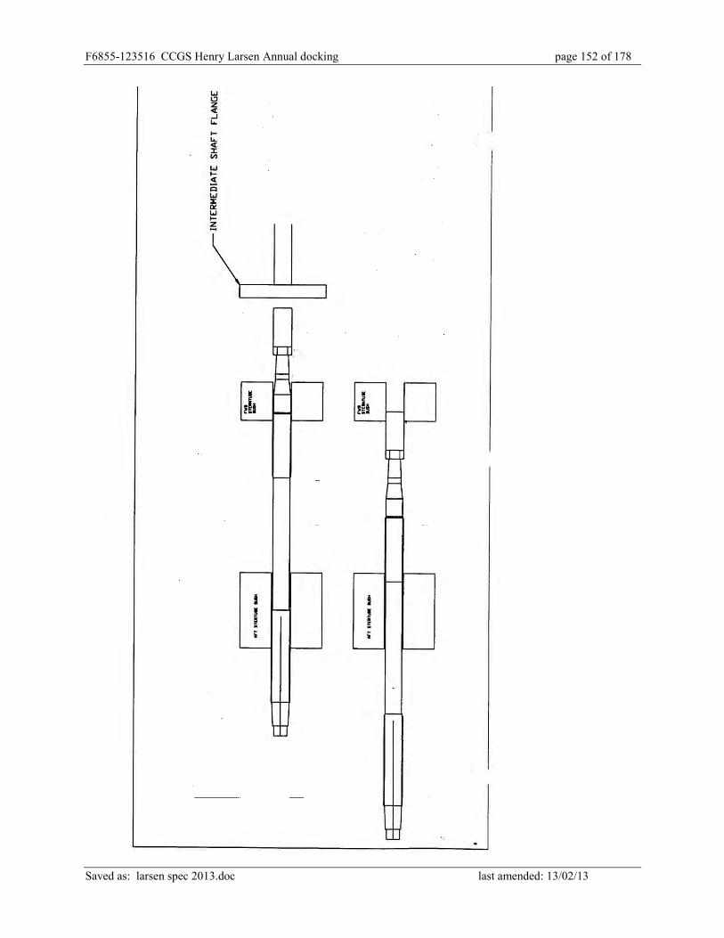
F6855-123516 CCGS Henry Larsen Annual docking page 152 of 178
Saved as: larsen spec 2013.doc last amended: 13/02/13
F6855-123516 CCGS Henry Larsen Annual docking page 153 of 178
Saved as: larsen spec 2013.doc last amended: 13/02/13
ED-03 PORT STERNSEAL
1) General Requirements:
The intent of this item is to unship the port shaft sternseal to facilitate removal of the port
tailshaft, service the port sternseal, and obtain TCMS credit for the sternseal.
2) References: Complete Title, drawing number and revision number.
A) Drawings. Wärtsilä H76738-02 Rev 4 GA of 750 Mod 720 Type MB Seal
B) Manuals. TM-MB-01 Issue D
3) Government Furnished Equipment.
Wärtsilä sternseal parts.
4) Contractor Furnished Equipment.
All non OEM parts and supplies.
5) Regulatory Requirements.
A) Transport Canada.
6) Coordination with other Specification Items.
HD Port Tailshaft
7) Safety Precautions
8) Statement of Work
1. Check free length of seal as per Sect 7.2.3 of the manual.
2. Disassemble necessary sea water and service air piping.
3. Disassemble seal as per Sect 13.6 of manual.
4. Refurbish seat as per Sect 13.7 of manual.

F6855-123516 CCGS Henry Larsen Annual docking page 154 of 178
Saved as: larsen spec 2013.doc last amended: 13/02/13
5. Ensure a new inflatable seal is installed if required.
6. Reassemble the seal as per Sect 13.8 of the manual.
9) Testing.
Test the seal installation as per Sect 13.8.12 of the manual and record findings.
10) Approval/Inspection/Documentation.
TCMS credit
Seal compression readings as per Sect 13.8.7 of the manual.
Seal test results within manufacturer’s specifications.
11) Removals and Protection
Contractor to ensure that no damage occurs to ship’s equipment and fittings as a result of this
work.
12) Restoration, cleanup, Lubrication.
All debris to be carried ashore, area to be left in good order.
13) Presentation of Readings etc.
1. Seal Test results from paragraph 9
2. Seal compression readings as per paragraph 10.
14) The contractor is required to provide the services of an authorized John Crane Marine Seal
FSR during the disassembly and reassembly of the seal. Contact: Barry Brodrick: Phone; (709)
747-4600 email: [email protected]. An allowance of $5,000.00 is to be bid for the
Wartsila/John Crane FSR and will be adjusted using PWGSC 1379 action.

F6855-123516 CCGS Henry Larsen Annual docking page 155 of 178
Saved as: larsen spec 2013.doc last amended: 13/02/13
ED-04 STEERING GEAR SURVEY
Manufacturer: WAGNER
Model: LA4-80-37-CB2
Serial: 10315
TCMS Field No. 3HH010
Steering Pump #1 3H046
Steering Pump #2 3H047
Emergency Steering Pump 3H048
Port Steering Motor 3E015
Stbd Steering Motor 3E016
Emergency Steering Motor 3E017
1. The intent of this item is to survey and obtain TCMS survey credit for the vessel’s
steering gear, rudder and hydraulic steering pumps/motors.
2. The contractor is to provide the services of an authorized WAGNER service
representative to supervise the overhaul, inspection and re-assembly requirements of
the Wagner Steering Gear. The contractor is to include the cost of technical services
in the overall quote. Allow $8000.00 to be adjusted up or down by 1379 action on
proof of invoices for transportation, meals and lodging for the service.
3. The contractor is to supply all materials unless otherwise specified.
4. With the ship’s Electrical Officer the contractor is to ensure the Lockout/Tagout is in
place. The contractor is to supply his/her own locks and tags but complete the
vessel’s Lockout/Tagout procedure.
Scope of Work
1. The two Wagner Steering Manifolds Model # M-100 Serial 486 are to be removed
from the top of the main reservoirs, crated and transported to the Wagner shops in

F6855-123516 CCGS Henry Larsen Annual docking page 156 of 178
Saved as: larsen spec 2013.doc last amended: 13/02/13
British Columbia to be opened, cleaned and rebuilt to manufacturer’s specifications.
Upon their return they are to be reattached to the steering gear prior to completion of
the work. A written report of all work preformed at the Wagner shop is to be
provided to the Chief Engineer and attending TCMS Inspector. Allow $5000.00 to be
adjusted up or down by 1379 action on proof of invoices for transportation, and
servicing.
2. Four hydraulic rams complete with their clevises, clevis pins, and bearings are to be
serviced.
3. Eight (8) - Fast Acting Relief Valves (FARVs) are to be serviced.
4. The 2 main hydraulic steering pumps and emergency hydraulic steering pump are to
be serviced.
5. The 2 main steering pump electric motors and emergency steering pump electric
motor are to be serviced.
Applicable Documents
WAGNER Technical Manual
Description of Work
1. Prior to any dismantling, the existing condition of each ram piston U-Cup packing is
to be checked. Steering to be placed hard over and downstream hose to be
disconnected from rams (2 rams). Rams to be pressurized and ram piston U-Cup
seals checked for leakage. Hoses to be replaced, steering to be placed hard over in
opposite direction and the remaining two rams checked in the same manner.
2. All four (4) cylinders including clevises, bearings, and clevis pins are to be marked
for location and let go from their mountings and hydraulic hoses.
3. The 4 hydraulic steering cylinders are to be disassembled and all parts cleaned and
laid out for inspection by the Chief Engineer and attending TCMS surveyor.

F6855-123516 CCGS Henry Larsen Annual docking page 157 of 178
Saved as: larsen spec 2013.doc last amended: 13/02/13
4. The cylinders are to be inspected by the Chief Engineer and attending TCMS
surveyor.
5. Any re-chroming of the rods and/or honing of the cylinders will be by 1379 action.
6. The cylinders are to be reassembled using new owner supplied seals.
7. The clevis bearings are to be cleaned and inspected by the Chief Engineer and
attending TCMS surveyor.
8. The clevis pins and bushings are to be cleaned and measured for wear and inspected
by the Chief Engineer and attending TCMS surveyor.
9. Eight (8) Fast Acting Relief Valves are to be opened up for inspection, parts cleaned,
and laid out for inspection.
10. Following inspection by the Chief Engineer and attending TCMS Surveyor the FARV
valves are to be reassembled.
11. The FARV valves are to be tested for correct operating pressure.
12. Following successful pressure test the FARVs are to be reinstalled in good order.
13. The level switch metering orifices are to be inspected and level switch proven
operational.
Hydraulic Pumpsets
1. The contractor is to provide the services of a manufacturer’s authorized service centre
to service the following pumpsets.
2. TA-300 Main Pumpset 2 of

F6855-123516 CCGS Henry Larsen Annual docking page 158 of 178
Saved as: larsen spec 2013.doc last amended: 13/02/13
3. TA 100 Emergency Pumpset 1 of
4. Remove hydraulic pumpsets ashore to contractor’s premises.
5. Perform pressure and flow test on hydraulic pumps to determine pump condition.
6. The Chief Engineer and attending TCMS surveyor are to witness the test and the test
results are to be provided to the Chief Engineer.
7. Any repairs or further servicing will be by 1379 action upon proof of invoice.
Hydraulic Reservoirs
Two main TA 300 pumpset reservoirs,
emergency TA100 pumpset reservoir,
locking pin TA 15 pumpset reservoir and
two FARV reservoirs to have oil drained and disposed of ashore
approximately 3000 litres total.
1. Reservoirs are to be opened out and internals thoroughly cleaned.
2. Reservoirs low level alarms to be proven operational.
3. Reservoirs to be inspected by Chief Engineer.
4. Upon completion reservoirs to be boxed up in good order using new contractor
supplied neoprene gaskets on covers.
5. Reservoirs to be refilled to operational levels using new contractor supplied Esso
Nuto 32 hydraulic oil. Contractor to quote on 3000 litres.
6. The new hydraulic fluid is to be filtered through a contractor provided filter assembly.
Completion
All removals reinstalled in good order.

F6855-123516 CCGS Henry Larsen Annual docking page 159 of 178
Saved as: larsen spec 2013.doc last amended: 13/02/13
1. On completion of inspections and reconditioning, cylinders are to be reinstalled in
their original locations. Clevis bearings are to be lubricated with owner supplied
grease.
2. Reinstall clevis pins with “this side down” labels pointing down.
3. All new contractor supplied hydraulic hoses are to be installed. The hoses are to be
flushed and pressure tested before installation. A certificate attesting to the hose
cleanliness and pressure testing is to be provided to the Chief Engineer. Hoses are to
be reconnected to their original locations using new “O” rings (Contractor supply).
4. The condition of each ram piston U-Cup packing is to be checked. Steering to be
placed hard over and downstream hose to be disconnected from rams (2 rams).
Rams to be pressurized and ram piston U-Cup seals checked for leakage. Hoses to be
replaced, steering to be placed hard over in opposite direction and the remaining two
rams checked in the same manner.
5. Ship’s personnel will operate the steering gear pumps to recharge the hydraulic
system and purge entrapped air from system.
6. The ship’s personnel will operate the system for up to 3 hours to test it to satisfaction
of Chief Eng and TCMS.
7. The entire system will be run up and proven operational using each main pumpset
individually and both main pumpsets together
8. Emergency pumpset will be proven operational.
9. FARV pumpsets to be proven operational.
10. Following test contractor to clean/replace all hydraulic filters on the system.
11. All work to be under the supervision and satisfaction of Wagner service
representative and Chief Engineer and attending TCMS Surveyor.

F6855-123516 CCGS Henry Larsen Annual docking page 160 of 178
Saved as: larsen spec 2013.doc last amended: 13/02/13
E-01 ANCHOR WINDLASS SURVEY
The intent of this item is to open the electric hydraulically anchor windlass for inspection and
survey by TCMS and Chief Engineer.
TCMS credit is to be obtained for the anchor windlass.
Make: Hytac Equipment Ltd
Model: HYTAC AWSO-48
SSB Field #: 3H049
Note, there are two (2) units to be dealt with, one Port and one Stbd.
1. Lockout/tagout
2. Anchors lowered to dock bottom.
3. Anchor chains removed from wildcats.
4. Brake bands are to be removed for inspection.
5. Brake drum to have a light skim machined from its surface (in situ).
6. Grease nipples and passageways to all brake assembly hinge pins to be proven clear.
7. Hinge pins to be proven free and operational.
8. Handwheel and shaft screw to be proven free and fully operational.
9. Condition of wildcat and cable stripper to be noted and recorded.
10. Windlass to be opened out to permit a full visual inspection of the gearbox internals.
All removals required for this inspection are to be performed in a professional
manner. Should any hydraulic removals be required, exposed hoses and ports are to
be capped immediately upon removal and caps removed upon completion. Ship’s
Electrical Officer to be contacted prior to any electrical removals.
11. Oil to be drained from gear case.
12. Gear case to be flushed and gear case internals wiped clean.

F6855-123516 CCGS Henry Larsen Annual docking page 161 of 178
Saved as: larsen spec 2013.doc last amended: 13/02/13
13. Windlass will have to be rotated to allow inspection of full circumference of both
pinion and bull gear.
14. Backlash between pinion and bull gear to be measured and recorded. Condition of
spherical bearings (4 of) and thrust washers to be noted and recorded.
15. All shaft bushing are to be exposed for inspection. Bushings and shafting in way of
bushings to be thoroughly cleaned. Bushing clearances to be taken and recorded.
16. Grease passageways ways to each bushing are to be proven clear.
17. Clutch assembly to be inspected and proven free and fully operational.
18. Any defects noted during opening up and inspection of windlass to be brought to
attention of Chief Engineer. Copies of all readings to be passed to Chief Engineer
immediately after readings are taken. Three typewritten copies of all readings are to
be passed to Chief Engineer upon to completion of refit.
19. Windlass internals are to be protected from the elements during the period they are
exposed.
20. All hydraulic hoses on the windlass and on the hydraulic power pack are to be
replaced.
21. Upon completion, windlass to be filled with new contractor supplied Esso Spartan EP
220 oil, approximately 80 litres each is required.
22. All removals are to be replaced in good order, using new jointing.
23. Brake adjustment to be proven satisfactory and able to hold drum against the pull of
the hydraulic motor.
24. All control functions to be proven operational. Windlass to be subject to test run for
one hour, to the satisfaction of Chief Engineer and attending TCMS surveyor.
25. All work is to be to the satisfaction of Chief Engineer and attending TCMS surveyor.

F6855-123516 CCGS Henry Larsen Annual docking page 162 of 178
Saved as: larsen spec 2013.doc last amended: 13/02/13
E-02 PROPULSION MOTOR MITCHELL BEARINGS
“Michell” Thrust Bearing
Manufacturer: Vickers Limited
Brg. No.: 91622 / S1
Fore & Aft Clearance: 0.040”
Journal Clearance: 0.026”
Lubricant: Esso Teresso 100 (168.1itres)
Fwd. Pedestal Bearing:
Manufacturer: Vickers Limited
Brg. No.: 505 0336 9925 701
Lubricant: Esso Teresso 100 (68.1itres)
The intent of this item is to open up, survey for TCMS and reassemble both the Port and Stbd
propulsion motor thrust bearing and the Port and Stbd motor pedestal bearings. TCMS credit is
to be obtained.
All materials are to be contractor supplied.
Scope of Work
The contractor is to open up propulsion motor fwd. pedestal bearing and aft thrust bearing for
cleaning and inspection, and re-assemble in good order upon completion.
Applicable Documents
Drawings and Instructions - CGE Instruction Manual for Industrial AC Machines.
Description of Work
1. Before any work on the thrust bearings occurs the Contractor is to take and record the
axial thrust clearance on the thrust pads and Weardown on the journal bearing.
Recording the axial thrust clearance will require jacking the shaft to record axial
F6855-123516 CCGS Henry Larsen Annual docking page 163 of 178
Saved as: larsen spec 2013.doc last amended: 13/02/13
movement. Recording the journal Weardown will require use of a depth micrometer.
Three typewritten copies to be passed to Chief Engineer before re-assembly.
2. Bearings to have oil drained from their sumps and oil disposed of ashore.
3. Bearing sumps to be flushed and cleaned.
4. All removals necessary to gain access to bearings, including wiring and piping to be
correctly marked to ensure correct replacement.
Thrust Bearing
1. Note: See instructions in CGE instruction manual Section 8, Page 8, before removing
top cover of thrust bearing.
2. Top cover to be removed for inspection of bearing internals. Bearing alignment
with shafting to be checked.
3. Pads and thrust shoes to be removed for inspection. Condition of thrust collar faces,
oil scraper, oil catchers and cooling coils to be noted.
4. Journal bearings to be removed for inspection. Journal bearing oil passages to be
proven clear. Journal thicknesses are to be measured and recorded. Three typewritten
copies to be passed to Chief Engineer before re-assembly.
5. Grease nipples for oil seals to be checked and their passages proven clear. Condition
of oil seals to be noted.
6. All temperature transducers, level switches and temperature thermometers to be
proven operational.
7. Cooling coils to be proven clear and to be hydrostatically tested to 120 psi.

F6855-123516 CCGS Henry Larsen Annual docking page 164 of 178
Saved as: larsen spec 2013.doc last amended: 13/02/13
Pedestal Bearing
1. Pedestal bearing to be opened out in a similar manner to thrust bearing. Inspection of
internals, testing, clearances and checking as per thrust bearing inspection, where
applicable.
2. Ship Safety credits to be received upon completion of inspection.
3. Thrust bearing to be re-assembled and boxed up in good order using all new gasket
material. All four (4) bearings to be filled with new Contractor supplied oil to their
operational level. All removals to be replaced as original. All wiring re-connections
to be proven correct.
Testing
1. Bearings to be operationally tested during sea trials.
2. The temperature probes to be proved operational to the vessel’s IGSS, via the
monitors in the Motor Control Room.
3. All work is to be to the satisfaction of the Chief Engineer and attending TCMS
Surveyor.

F6855-123516 CCGS Henry Larsen Annual docking page 165 of 178
Saved as: larsen spec 2013.doc last amended: 13/02/13
E-03 CENTRE MAIN ENGINE SUMP TANK CLEANING
Location Frame 94 – 112, Engine room Volume 8.9 m3 Intent
The intent of this item is to open up, clean and close up the centre main engine
lubricating oil sump tank.
The ship’s crew will be overhauling the main engine for TCMS credit while the sump
tank is being cleaned out.
The sump tank is considered confined spaces under the Safety Management System.
1. The sump tank presently contains used BP ENERGOL DS3-153 or equivalent
main engine lube oil. Contractor shall remove and dispose of this oil, for bidding
purposes quote on 5 m3 of oil. Proof of quantity and disposal under applicable
environmental regulations of oil removed from the ME LO tank is to be provided
to the Chief Engineer.
2. The Contractor shall supply the Owner's Representative with marine chemists or
other qualified person’s certificates in accordance with CCG/SSB TP 3177E
before any work is commenced in the Sump tank. Certificates shall clearly state
the type of work permitted and shall be renewed as required by regulations.
Copies of the certificates are to be posted in conspicuous locations for the
information of the Ship's and Contractor's personnel.
3. The Contractor shall ensure that any work carried out in confined spaces as
defined by the Canada Labour Code must comply fully with all provisions of the
code.

F6855-123516 CCGS Henry Larsen Annual docking page 166 of 178
Saved as: larsen spec 2013.doc last amended: 13/02/13
4. The Contractor shall note that the Coast Guard has an Enclosed Space Entry
Policy in place. The policy is Section 7.D.9 and 7.D.9 (N) of the Fleet Safety
Manual, copy of which is in the attached safety annex. The Contractor shall be
responsible to ensure the Contractor’s personnel, including any subcontractors,
follow the policy.
5. Contractor shall supply any ventilation equipment required for the gas free
Certificate and the certificate’s continued validity for the duration of the work.
6. Contractor shall supply any temporary lighting required. Lighting to be removed
upon completion.
7. The contractor shall remove the manhole cover to gain access for cleaning.
Contractor shall clean all sludge, dirt and debris from tank. Manhole covers are
located on the forward and after ends of the sump tank. All refuse removed from
the tank shall be removed from the ship daily. The entire interior of the tank shall
be pressure washed with hot water (70 degs C) using a minimum of 2000 psi
wash. All water in tanks shall be pumped out and disposed of ashore by
Contractor.
8. The entire interior of the tank shall be wiped dry with lint free rags after cleaning
to prevent flash rusting of steel surfaces.
9. The sump tank vent piping and sounding pipe shall be proven clear.
10. In conjunction with the ship’s Electrical Officer, tank level transmitter shall be
proven operational.
11. Contractor shall insure that surrounding areas affected by the cleaning be left in
an ‘as found’ condition

F6855-123516 CCGS Henry Larsen Annual docking page 167 of 178
Saved as: larsen spec 2013.doc last amended: 13/02/13
12. Upon completion of the cleaning, the tank shall be inspected by Chief Engineer or
delegate.
13. Contractor shall install cleaned manhole covers on tank using a new contractor
supplied gasket, approved by the gasket material manufacturer for use with hot
engine lubricating oil. Proof of suitability must be provided before the gasket is
installed. Studs shall be coated with an approved anti-seize compound.
14. All work is to be to the satisfaction of the Chief Engineer.
15. The ship’s crew will refill the sump tank with oil.

F6855-123516 CCGS Henry Larsen Annual docking page 168 of 178
Saved as: larsen spec 2013.doc last amended: 13/02/13
E-04 CYLINDER HEAD SERVICING Engine Wärtsilä VASA 32 Cylinder Head part number 120-060 Valves per head: 2 inlet, 2 exhaust, 1 relief, 1 indicator valve, 1 air start valve Cylinder Head Weight: 150 Kg Manufacturer’s replacement parts will be owner supplied.
1. The intent of this item is to service and obtain TCMS credit for 16 cylinder heads as detailed.
2. The Contractor is to take the cylinder heads from the stbd side of the vessel’s boat deck and return the cylinder heads to the stbd side of the vessel’s Boat Deck.
3. Sixteen- (16) SME cylinder heads to be transported from ship to an Authorized
Wärtsilä Shop for TCMS inspection, cleaning and refurbishing. All maintenance carried out on the cylinder heads to be as per recommendations in Wartsila Manual Section 12." Cylinder Head with Valves", available from Chief Engineer.
4. All work to be completed within a TWO week time frame and cylinder heads to be
transported back to ship, upon completion. (Stbd. Side Boat Deck) 6.02 Heads to be stripped, thoroughly cleaned in a caustic bath and inspected for damage. Any damage discovered is to be brought to the attention of the Chief Engineer.
5. Contractor to arrange for inspection of cleaned heads by TCMS inspector.
6. Inlet valve seats to be lapped/ground to manufacturer’s specifications. Any seats
ground beyond specifications to be renewed by 1379 action. Contractor to bid on renewing 4 Inlet valve seats. Quote cost per head.
7. Exhaust valve seats are to be removed for inspection of valve seat O-ring landings and replaced using new O-Rings. Any landings found to be pitted are to be machined to remove pitting and oversize seats with new O-rings fitted.
8. Contractor to quote on machining 16 cylinder head exhaust valve seat landings to
remove pitting in landing area. Quote cost per head.
9. All original inlet and exhaust valves are to be replaced with new wide seat Stellite valves (Owner supply). All original removed inlet and exhaust valves to be returned to ship.
10. Each cylinder head is to be heated (whole) to 100 deg. C and hydrostatically tested
with a test pressure of 8 to 10 bar for ½ hr. Contractor to arrange for inspection of heads by TCMS inspector.

F6855-123516 CCGS Henry Larsen Annual docking page 169 of 178
Saved as: larsen spec 2013.doc last amended: 13/02/13
11. Valve springs to be checked for cracks, corrosion or wear marks. Any defective springs to be renewed.
12. Any valve guides found to beyond manufacturer’s limits are to be replaced.
13. Valve rotators to be disassembled, cleaned and laid out for inspection. Rotators to be
rebuilt using new parts, where required.
14. Air start valves to be completely disassembled, cleaned and laid out for inspection. Valves to be rebuilt using new parts, where required.
15. Relief valves to be completely disassembled, cleaned and laid out for inspection.
Valves to be rebuilt using new parts, where required. All valves to be calibrated and set to lift according to manufacturer's recommended pressure.
16. Heads to be re-assembled in good order, as per manufacturer’s specifications.
17. Any Wärtsilä parts supplied by Contractor to be by 1379 action and returned to the
vessel.
18. Heads to be delivered to ship - Stbd Side Boat Deck
19. Contractor to provide written documentation of inspection by TCMS inspector, including name of the attending inspector, and time and date of inspection. Such documentation to be provided to the Chief Engineer.

F6855-123516 CCGS Henry Larsen Annual docking page 170 of 178
Saved as: larsen spec 2013.doc last amended: 13/02/13
E-05 CHARGE AIR COOLER HYDROSTATIC TESTING
The intent is to obtain TCMS credit for the inspection of three charge air coolers.
Item Field Number M/E #2 Charge Air Cooler #1 3H006 M/E #2 Charge Air Cooler #2 3H007
Aux Gen #1 Charge Air Cooler 3H016
1. Contractor shall remove these coolers from Main Engine #2 (Centre Engine & Aux Generator #1) and place them in a safe position for the remainder of the work.
2. The coolers shall be cleaned of any old gasket materials, and the air side cleaned with a high pressure wash and de-greaser. The coolers are then to be arranged so that the attending TCMS Inspector can visually examine them.
3. Contractor shall apply a hydrostatic test is to be applied at 8 bar to prove them watertight to the satisfaction of the attending TCMS Inspector. All blanks, gaskets, gauges, etc to carry out hydrostatic testing shall be supplied by the Contractor.
4. The coolers are to be installed back on the engine in good order using new ship supplied gaskets (Wärtsilä part number 156-015).
5. Contractor will be responsible to ensure TCMS credit is obtained upon the satisfaction of
the attending Inspector. 6. All work is to be to the satisfaction of the Chief Engineer.
7. The engines will be tested operational to the satisfaction of the Chief Engineer on sea
trails.
8. All waste water and debris to be removed from the machinery spaces, deck plates and bilges.

F6855-123516 CCGS Henry Larsen Annual docking page 171 of 178
Saved as: larsen spec 2013.doc last amended: 13/02/13
E-06 ELECTRICALLY DRIVEN PUMP OVERHAULS Intent: The intent is to open the listed electrically driven pumps for inspection and credit by TCMS.
Field Number Name Manufacture Model Number 3H022 Cent Cooling RW #2 Iron AS QV-8/300EA 3H032 Cent Cool Aux FW #1 Iron AS QV8/300 3H033 Cent Cool Aux FW #2 Iron AS 3H037 F/O Booster P/P #1
Day Tank Roto King Pump AK4193
3H038 F/O Booster P/P #2 Day Tank
Roto King Pump AK4193
3H043 Bilge & Ballast P/p #1 Iron AS C.BN.H. 125-100/250
3H044 Bilge & Ballast P/p #2 Iron AS C.BN.H. 125-100/250
1. With the ship’s Electrical Officer the contractor shall ensure the Lockout/Tagout is in
place on Pumps being worked on. The contractor shall supply his/her own locks and tags
but complete the vessel’s Lockout/Tagout procedure.
2. With the assistance of the Ship’s Crew the Contractor shall ensure that the suction and
discharge, valve for each pump, has a proper Lockout/Tagout in place. The contractor
shall supply his/her own locks and tags but complete the vessel’s Lockout/Tagout
procedure.
3. Contractor shall dismantle each pump, clean and lay out the components for inspection
by the Chief Engineer and the attending TCMS inspector. Any worn or damaged parts
are to be replaced, by owner supplied parts. Contractor shall be responsible for arranging
the attendance of the TCMS Inspector.

F6855-123516 CCGS Henry Larsen Annual docking page 172 of 178
Saved as: larsen spec 2013.doc last amended: 13/02/13
4. Any wear ring measurements are to be taken and recorded.
5. Upon completion of the inspection, the pumps are to be re-assembled in good order,
connected to their respective electric motors and test run to the satisfaction of the Chief
Engineer and the attending TCMS Inspector.
6. Contractor shall ensure that area worked is left in as found condition.
7. The Contractor shall provide a Service Report including the as found condition, work
performed, wear ring clearances, and any parts used.

F6855-123516 CCGS Henry Larsen Annual docking page 173 of 178
Saved as: larsen spec 2013.doc last amended: 13/02/13
E-07 ANNUAL REFRIGERATION SYSTEMS INSPECTION The intent of this item is to ensure the refrigeration systems are operating in an efficient and environmentally safe manner under the Halocarbon Regulations. The contractor is to provide the services of a service person properly licensed under provincial or federal regulations to perform such work to conduct a complete and through examination of the following Halocarbon containing systems including compressor units, piping and evaporators and all associated components:
1. Domestic Refrigeration System: Carrier VM5F60-12 2 units MP39 (2 of) 2. Cargo Refrigeration System: Carrier VM5F40-12 2 units MP39 (2 of) 3. Accommodation A/C Chillers: Carrier 5H40 2 units R-22 (2 of) 4. Electronic Equip. Rm A/C unit: Bronswerk Type NSN-3B 1 unit R-22 (1 of) 5. A/C units for MCR Carrier 90 MA 012 2 units R-22 (2 of)
1. The Domestic refrigeration system, the Cargo refrigeration system, and the water chiller for the Air conditioning system each have two compressors and condensers. There are 5 cooled spaces on the Domestic system, and a single cooled space on the Cargo system. There are two self contained A/C units for the MCR and one self contained A/C unit for the Electronics Equipment Room.
2. The Contractor is to change all filter/drier elements systems. The Contractor is to
perform oil and filter changes on the 9 compressors (1 through 5).
3. All materials are to be contractor supplied by 1379 action upon proof of invoice.
4. The Contractor is to provide a Service Report including the as found condition, work performed, and any parts used.
5. All systems are to be leak tested when systems are in operation. All the components
and piping to be examined. Any necessary repairs to be by 1379 action, after estimates are reviewed by the Chief Engineer.
6. The Contractor is to provide written documentation of inspection to satisfy
Environment Canada regulations to the Chief Engineer.
7. The Contractor is to complete the vessel’s halocarbon logbook noting all work performed on each system.
8. All work is to be to the satisfaction of the Chief Engineer.

F6855-123516 CCGS Henry Larsen Annual docking page 174 of 178
Saved as: larsen spec 2013.doc last amended: 13/02/13
E-08 MACHINERY SPACE BILGE CLEANING
.1 The intent of this item is to clean the tank top, bilges, piping, machinery seats and
frames below the deck plates in the machinery spaces of all debris and oil and
sludge.
.
.2 This item is to be scheduled for the last week of the contract period.
.3 The contractor is to supply all material and labour to effectively degrease and
clean the area beneath the deck plates in Generator Room, Auxiliary Machinery
Room, Propulsion Motor Room, and Bubbler Manifold Compartment.
.4 All water, oil, sludge and debris is to be removed ashore.
Area of Generator Room 283 m2.
Area of Auxiliary Machinery Room 202 m2
Area of Propulsion Motor Room 228 m2
Area of Bubbler Manifold Compartment 34 m2
.5 Any chemicals used are to be designed and approved for the intended use by the
chemical manufacturer. Any chemicals are to be compatible with and intended for
use with a marine Oily Water Separator system by the chemical manufacturer
.6 The contractor is to supply product details and instructions and current MSDS on
cleaning chemical used to Chief Engineer before the chemical is used or brought
aboard the vessel.
.7 The contractor is not to use any cleaning chemical capable of generating toxic or
excessively volatile fumes under any circumstances.

F6855-123516 CCGS Henry Larsen Annual docking page 175 of 178
Saved as: larsen spec 2013.doc last amended: 13/02/13
.8 The contractor is to use warning Tape and Barriers to safely mark areas where the
deck plates are up or are unsecured.
.9 This work will include the marking, removal, and re-installation of a number of
steel deckplates as well as the immediate removal ashore and disposal of waste
water and solutions from the Bilges and Tank tops.
.10 A pressurized water cleaning System is to be used to clean the bilges/tanktop of
all water, oil , sludge and debris removed with a pumping/vacuum system.
.11 Care is to taken to protect machinery using plastic barrier as necessary.
.12 Areas and equipment above the deck plates are not to be over sprayed.
.13 All liquids and debris remaining as result from the cleaning shall be continuously
removed from the vessel. Ships Systems and equipment shall not be used to
dispose of any liquids or debris.
.14 All bilge wells shall be shown to be clean upon completion of all work. Bilge
float alarms in the wells shall be proven operational.
.15 Deck plates to be re-installed with all securing screws in place.
.16 All work is to be to satisfaction of the Chief Engineer.

F6855-123516 CCGS Henry Larsen Annual docking page 176 of 178
Saved as: larsen spec 2013.doc last amended: 13/02/13
L-01 POWER PANEL INSTALLATION The intent of this Specification is to supply, install and connect a new 230 Volt, 3 phase Panel fitted with two 60 amp breakers for branch circuits, in the cross alleyway aft of Galley, on the Main deck, and three cable runs. These cable runs will entail the power supply to the 230 vac 3 phase power panel and the two 3 phase branch circuit runs form the 230 volt power panel to the specified locations. 1. The power supply cable for the new panel, shall be continuous without the use of
Junction Boxes, and ran from the, owner supplied 175 amp breaker on the 230 vac section of the Ship’s Service Switchboard and down through the watertight transit into the Auxiliary Machinery Space cable tray above Fire Pump #1, continuing inboard and aft through the watertight transit on the Port side of the Aft watertight door into the lower Propulsion Motor Room, continuing to the stbd side up through the deckhead transit into the upper level of Propulsion Motor Room, continuing aft in the existing cable trays and through the watertight deckhead transit, above the air blowers section on the Stbd Cycloconverter, and into Cross Alleyway on the Main Deck adjacent to the aft entrance door to the Crew’s Mess. This run measures approx 150 ft (46M)
2. The two 60 amp branch circuits shall be continuous without the use of Junction Boxes,
and ran from the 230 vac 3 phase panel into the existing adjacent cable tray, up and above to the outboard side of the Aft Crew’s Mess Entrance, through the existing watertight transit into the Crew’s Mess, continuing forward where one branch circuit shall be run into the Crew’s Pantry. This run measures approx 50 ft (15M) The other branch circuit shall continue forward to approx frame 56 to the outboard side and up through the Deckhead and into the Officer’s Pantry. This location in the Officer’s Pantry will require a watertight penetration (kickpipe) installation by the contractor. This run measures approx 55 ft (17M).
3. All work shall be in accordance with Canadian Electrical Code, TP127E, and IEEE Std
45. 4. All cabling to be suitably sized and be bronze armoured marine braid. 5. The Contractor shall ensure all watertight transits opened during this installation are
resealed . 6. The Contractor shall perform insulation testing on these new cable runs after installation
to insure their integrity. This shall be witnessed by the Chief Engineer’s delegate. If the test results are unsatisfactory, and cannot be corrected to the satisfaction of the Chief Engineer, the contractor will replace the entire cable run(s) at their expense
7. All work shall be to the satisfaction of Owner's representative.

F6855-123516 CCGS Henry Larsen Annual docking page 177 of 178
Saved as: larsen spec 2013.doc last amended: 13/02/13
L-02 STEERING GEAR MOTORS
The intent of this item is to service the port and stbd steering motors for survey and credit from
TCMS. Work to be done on two main Steering Motors and one Emergency Steering Motor.
Main Motor: Baldor Model 4316T-5
575Volt 68 Amp 3PH 60 Hz
75 HP 1775 RPM
Bearings DE 6313 NDE 6312
Emergency Motor: Baldor Model 37E627X110
575 Volt 10.6 Amp 3PH 60 Hz
10 HP 1725 RPM
TCMS Field No’s
Port Steering Motor 3E015
Stbd Steering Motor 3E016
Emerg Steering Motor3E017
1. With the ship’s Electrical Officer the contractor is to ensure the Lockout/Tagout is in
place. The contractor is to supply his/her own locks and tags but complete the vessel’s
Lockout/Tagout procedure.
2. Each motor assembly to be removed and transported to Contractor's facility for servicing.
Wires to be tagged for proper rotational connection. Any removals necessary to facilitate
the removal of the motor unit is the responsibility of the Contractor. Contractor to be
responsible for cost and replacement of any damages.

F6855-123516 CCGS Henry Larsen Annual docking page 178 of 178
Saved as: larsen spec 2013.doc last amended: 13/02/13
3. Each motor unit to be dismantled for inspection, cleaning and bearing renewal. The
contractor is to renew all bearings. Bearings to be SKF or equivalent bearings as per
original.
4. Upon completion, checks for vibration and proper rotation are to be performed. Motor
starting and running current readings, Megger readings and motor vibration to be taken
and recorded as before, as well as the numbers to identify the new bearing installed on
each end of each motor. Typewritten copy and electronic copy to be passed to ship's
Senior Electrical Officer and to Chief Engineer with all information listed as above.
5. Any paint work disturbed as a result of cutting, burning or welding is to be wire brushed
clean and coated with primer.
6. Upon completion of all work all disturbed items to be installed in good order, as per
original. All dirt and debris resulting from this work is to be disposed of ashore.
7. Contractor to supply all parts and material. Contractor will be responsible to arrange
inspections as necessary for approval by attending TCMS surveyor.
8. All work to the satisfaction of Owner's representative and attending TCMS surveyor.