cccna3 cap1
50
Welcome Welcome to the CCNA Exploration LAN Switching and Wireless course. The goal is to develop an understanding of how switches are interconnected and configured to provide network access to LAN users. This course also teaches how to integrate wireless devices into a LAN. The specific skills covered in each chapter are d escribed at the start of each chapter. More than just information This computer-based learning environment is an important part of the overall course experience for students and instructors in the Networking Academy. These online course materials are designed to be used along with several other instructional tools and activities. These include: Class presentation, discussion, and practice with your instructor Hands-on labs that use networking equipment within the Networking Academy classroom Online scored assessments and a matching grade book Packet Tracer simulation tool Additional software for classroom activities A global community When you participate in the Networking Ac ademy, you are joining a global community linked by common goals and technologies. Schools, colleges, universities and other entities in over 160 countries participate in the program. A visualization of the global Networking Academy community can be viewed via http://www.academynetspace.com. The material in this course encompasses a broad range of technologies that facilitate how people work, live, play, and learn by communicating with voice, video, and other data. Networking and the Internet affect peop le differently in different parts of the world. Although we have worked with instructors from around the world to create these materials, it is important that you work with your instructor and fellow students to make the material in this course applicable to your local situation. Keep in Touch These online instructional materials, as well as the rest of the course tools, are part of the larger Networking Academy. The student, instructor, and administrator portal for the program is located at http://www.cisco.com/web/learning/netacad/index.html. There you will obtain access to the other tools in the program such as the assessment server and student grade book, as well as informational updates and other relevant links. A global community When you participate in the Networking Ac ademy, you are joining a global community linked by common goals and technologies. Schools, colleges, universities and other entities in over 160 countries participate in the program. A visualization of the global Networking Academy community can be viewed via http://www.academynetspace.com. The material in this course encompasses a broad range of technologies that facilitate how people work, live, play, and learn by communicating with voice, video, and other data.
Transcript of cccna3 cap1

8/7/2019 cccna3 cap1
http://slidepdf.com/reader/full/cccna3-cap1 1/50
Welcome
Welcome to the CCNA Exploration LAN Switching and Wireless course. The goal is todevelop an understanding of how switches are interconnected and configured to provide
network access to LAN users. This course also teaches how to integrate wireless devices
into a LAN. The specific skills covered in each chapter are described at the start of eachchapter.
More than just information
This computer-based learning environment is an important part of the overall courseexperience for students and instructors in the Networking Academy. These online course
materials are designed to be used along with several other instructional tools and
activities. These include:
Class presentation, discussion, and practice with your instructor
Hands-on labs that use networking equipment within the Networking Academy
classroom
Online scored assessments and a matching grade book Packet Tracer simulation tool
Additional software for classroom activitiesA global community
When you participate in the Networking Academy, you are joining a global community
linked by common goals and technologies. Schools, colleges, universities and other
entities in over 160 countries participate in the program. A visualization of the globalNetworking Academy community can be viewed via http://www.academynetspace.com.
The material in this course encompasses a broad range of technologies that facilitate howpeople work, live, play, and learn by communicating with voice, video, and other data.
Networking and the Internet affect people differently in different parts of the world.Although we have worked with instructors from around the world to create thesematerials, it is important that you work with your instructor and fellow students to make
the material in this course applicable to your local situation.
Keep in Touch
These online instructional materials, as well as the rest of the course tools, are part of the
larger Networking Academy. The student, instructor, and administrator portal for the
program is located at http://www.cisco.com/web/learning/netacad/index.html. There youwill obtain access to the other tools in the program such as the assessment server and
student grade book, as well as informational updates and other relevant links.
A global communityWhen you participate in the Networking Academy, you are joining a global community
linked by common goals and technologies. Schools, colleges, universities and other
entities in over 160 countries participate in the program. A visualization of the globalNetworking Academy community can be viewed via http://www.academynetspace.com.
The material in this course encompasses a broad range of technologies that facilitate how
people work, live, play, and learn by communicating with voice, video, and other data.

8/7/2019 cccna3 cap1
http://slidepdf.com/reader/full/cccna3-cap1 2/50
Networking and the Internet affect people differently in different parts of the world.
Although we have worked with instructors from around the world to create these
materials, it is important that you work with your instructor and fellow students to makethe material in this course applicable to your local situation.
Keep in TouchThese online instructional materials, as well as the rest of the course tools, are part of the
larger Networking Academy. The student, instructor, and administrator portal for the
program is located at http://www.cisco.com/web/learning/netacad/index.html. There youwill obtain access to the other tools in the program such as the assessment server and
student grade book, as well as informational updates and other relevant links.
3. Practice. Learning new skills requires practice. We believe this is so important to e-
learning that we have a special name for it. We call it e-Doing. It is very important thatyou complete the activities in the online instructional materials and that you also
complete the hands-on labs and Packet Tracer activities.
4. Practice again. Have you ever thought that you knew how to do something and then,when it was time to show it on a test or at work, you discovered that you really had not
mastered it? Just like learning any new skill like a sport, game, or language, learning aprofessional skill requires patience and repeated practice before you can say you have
truly learned it. The online instructional materials in this course provide opportunities for
repeated practice for many skills. Take full advantage of them. You can also work with
your instructor to extend Packet Tracer, and other tools, for additional practice as needed.5. Teach it. Teaching a friend or colleague is often a good way to reinforce your own
learning. To teach well, you will have to work through details that you may have
overlooked on your first reading. Conversations about the course material with fellowstudents, colleagues, and the instructor can help solidify your understanding of
networking concepts.
6. Make changes as you go. The course is designed to provide feedback through
interactive activities and quizzes, the online assessment system, and through structured
interactions with your instructor. You can use this feedback to better understand whereyour strengths and weaknesses are. If there is an area that you are having trouble with,
focus on studying or practicing more in that area. Seek additional feedback from your
instructor and other students.
Explore the world of networkingThis version of the course includes a special tool called Packet Tracer 4.1. Packet Tracer
is a networking learning tool that supports a wide range of physical and logical
simulations. It also provides visualization tools to help you to understand the internalworkings of a network.
The pre-made Packet Tracer activities consist of network simulations, games, activities,and challenges that provide a broad range of learning experiences.
Create your own worlds
8/7/2019 cccna3 cap1
http://slidepdf.com/reader/full/cccna3-cap1 3/50
You can also use Packet Tracer to create your own experiments and networking
scenarios. We hope that, over time, you consider using Packet Tracer – not only for
experiencing the pre-built activities, but also to become an author, explorer, andexperimenter.
The online course materials have embedded Packet Tracer activities that will launch oncomputers running Windows® operating systems, if Packet Tracer is installed. This
integration may also work on other operating systems using Windows emulation.
Course Overview
The primary focus of this course is on LAN switching and wireless LANs. The goal is to
develop an understanding of how a switch communicates with other switches and routers
in a small- or medium-sized business network to implement VLAN segmentation.
This course focuses on Layer 2 switching protocols and concepts used to improve
redundancy, propagate VLAN information, and secure the portion of the network where
most users access network services.
Switching technologies are relatively straightforward to implement; however, as withrouting, the underlying protocols and algorithms are often quite complicated. This course
will go to great lengths to explain the underlying processes of the common Layer 2
switching technologies. The better the underlying concepts are understood, the easier it is
to implement, verify, and troubleshoot the switching technologies.
Each switching concept will be introduced within the context of a single topology for
each chapter. The individual chapter topologies will be used to explain protocoloperations as well as providing a setting for the implementation of the various switching
technologies.
The labs and Packet Tracer activities used in this course are designed to help you develop
an understanding of how to configure switching operations while reinforcing the concepts
learned in each chapter.
Chapter 1 LAN Design — In Chapter 1, you learn the fundamental aspects of designing
local area networks. In particular, hierarchical network design utilizing the core-
distribution-access layer model is introduced and referenced throughout the remainder of the course.
Chapter 2 Basic Switch Concepts and Configuration — Chapter 2 introduces switchforwarding methods, symmetric and asymmetric switching, memory buffering, and Layer
2 and Layer 3 switching. You are introduced to navigating the Cisco IOS CLI on a
Catalyst 2960 and performing an initial switch configuration. An integral role of a switchadministrator is to maintain a secure network; to this end, you learn to configure various
passwords on the switch as well as SSH to mitigate common security attacks.
8/7/2019 cccna3 cap1
http://slidepdf.com/reader/full/cccna3-cap1 4/50
Chapter 3 VLANs — Chapter 3 presents the types of VLANs used in modern switched
networks. It is important to understand the role of the default VLAN, user/data VLANs,
native VLANs, the management VLAN, and voice VLANs. VLAN trunks with IEEE802.1Q tagging facilitate inter-switch communication with multiple VLANs. You learn to
configure, verify, and troubleshoot VLANs and trunks using the Cisco IOS CLI.
Course Overview Continued
Chapter 4 VTP — VTP is used to exchange VLAN information across trunk links,
reducing VLAN administration and configuration errors. VTP allows you to create aVLAN once within a VTP domain and have that VLAN propagated to all other switches
in the VTP domain. VTP pruning limits the unnecessary propagation of VLAN traffic
across a LAN by determining which trunk ports forward which VLAN traffic. You learn
to configure, verify, and troubleshoot VTP implementations.
Chapter 5 STP — STP makes it possible to implement redundant physical links in a
switched LAN by creating a logical loop-free Layer 2 topology. By default Cisco
switches implement STP in a per-VLAN fashion. The configuration of STP is fairlystraightforward, but the underlying processes are quite complicated. IEEE 802.1D
defined the original implementation of spanning-tree protocol. IEEE 802.1w defined animproved implementation of spanning tree called rapid spanning tree protocol. RSTP
convergence time is approximately five times faster than convergence with 802.1D.
RSTP introduces several new concepts, such as link types, edge ports, alternate ports,
backup ports, and the discarding state. You will learn to configure both the original IEEE802.1D implementation of STP as well as the newer IEEE 802.1w implementation of
spanning tree.
Chapter 6 Inter-VLAN Routing — Inter-VLAN routing is the process of routing traffic
between different VLANs. You learn the various methods of inter-VLAN routing. You
learn to implement inter-VLAN routing in the router-on-a-stick topology, where a trunk link connects a Layer 2 switch to a router configured with logical subinterfaces paired in
a one-to-one fashion with VLANs.
Chapter 7 Basic Wireless Concepts and Configuration — Wireless LAN standards are
evolving for voice and video traffic, with newer standards being supported with quality of
service. An access point connects to the wired LAN provides a basic service set to client
stations that associate to it. SSIDs and MAC filtering are inherently insecure methods of securing a WLAN. Enterprise solutions such as WPA2 and 802.1x authentication enable
very secure wireless LAN access. End users have to configure a wireless NIC on their
client stations which communicates with and associates to a wireless access point. Whenconfiguring a wireless LAN, you should ensure that the devices have the latest firmware
so that they can support the most stringent security options.
For the small- and medium-sized business, communicating digitally using data, voice,and video is critical to business survival. Consequently, a properly designed LAN is a
fundamental requirement for doing business today. You must be able to recognize a well-
designed LAN and select the appropriate devices to support the network specifications of
a small- or medium-sized business.
8/7/2019 cccna3 cap1
http://slidepdf.com/reader/full/cccna3-cap1 5/50
In this chapter, you will begin exploring the switched LAN architecture and some of the
principles that are used to design a hierarchical network. You will learn about convergednetworks. You will also learn how to select the correct switch for a hierarchal network
and which Cisco switches are best suited for each network layer. The activities and labs
confirm and reinforce your learning.
When building a LAN that satisfies the needs of a small- or medium-sized business, your
plan is more likely to be successful if a hierarchical design model is used. Compared toother network designs, a hierarchical network is easier to manage and expand, and
problems are solved more quickly.
Hierarchical network design involves dividing the network into discrete layers. Eachlayer provides specific functions that define its role within the overall network. By
separating the various functions that exist on a network, the network design becomes
modular, which facilitates scalability and performance. The typical hierarchical design
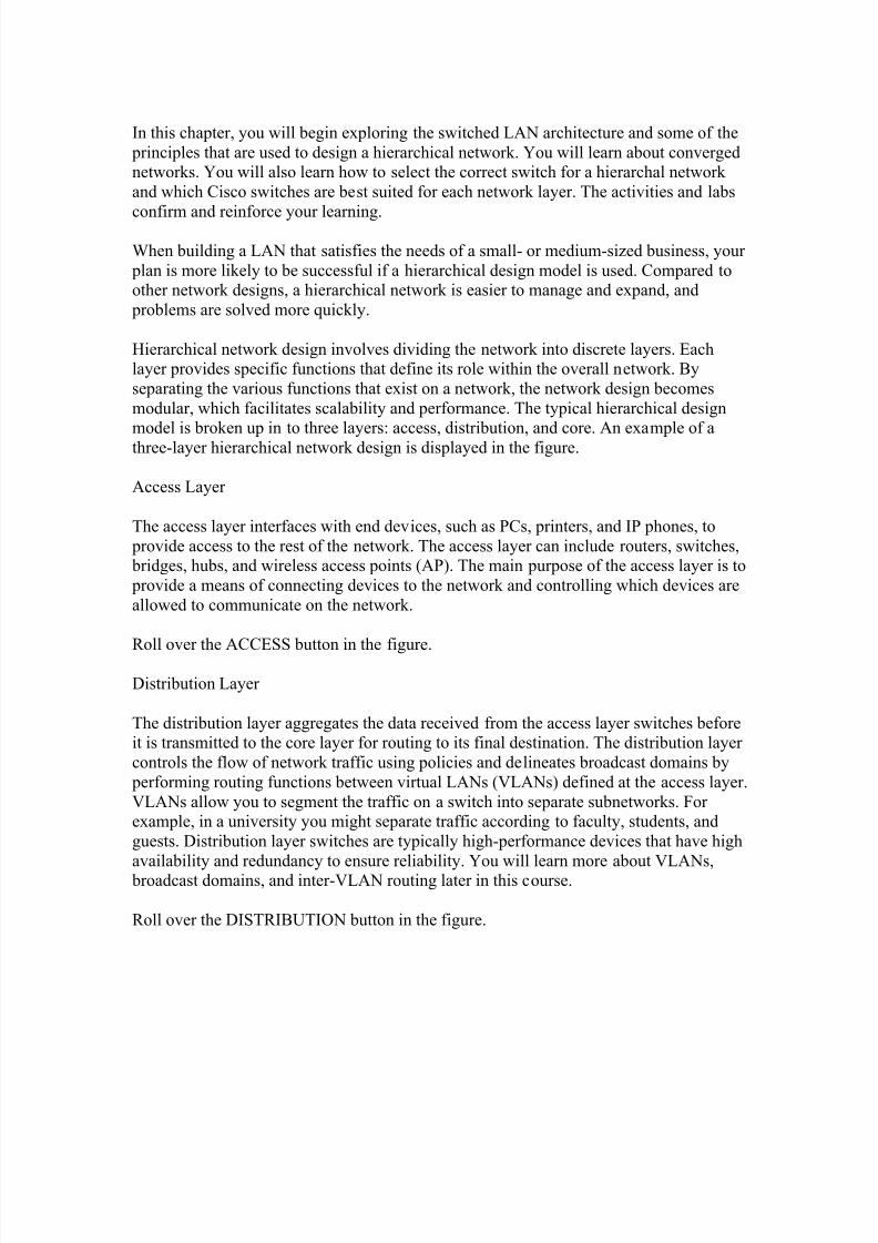
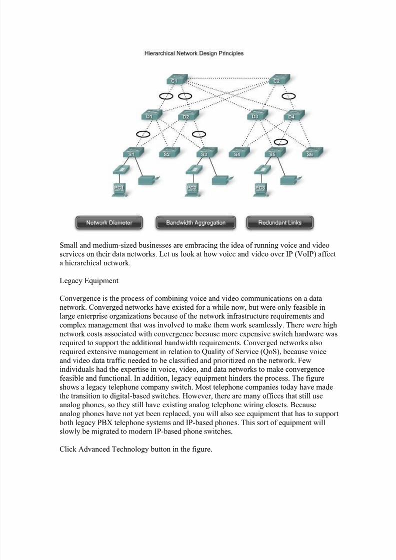
model is broken up in to three layers: access, distribution, and core. An example of athree-layer hierarchical network design is displayed in the figure.
Access Layer
The access layer interfaces with end devices, such as PCs, printers, and IP phones, to
provide access to the rest of the network. The access layer can include routers, switches,bridges, hubs, and wireless access points (AP). The main purpose of the access layer is to
provide a means of connecting devices to the network and controlling which devices are
allowed to communicate on the network.
Roll over the ACCESS button in the figure.
Distribution Layer
The distribution layer aggregates the data received from the access layer switches beforeit is transmitted to the core layer for routing to its final destination. The distribution layer
controls the flow of network traffic using policies and delineates broadcast domains by
performing routing functions between virtual LANs (VLANs) defined at the access layer.
VLANs allow you to segment the traffic on a switch into separate subnetworks. For example, in a university you might separate traffic according to faculty, students, and
guests. Distribution layer switches are typically high-performance devices that have high
availability and redundancy to ensure reliability. You will learn more about VLANs,broadcast domains, and inter-VLAN routing later in this course.
Roll over the DISTRIBUTION button in the figure.
8/7/2019 cccna3 cap1
http://slidepdf.com/reader/full/cccna3-cap1 6/50
Core Layer
The core layer of the hierarchical design is the high-speed backbone of the internetwork.The core layer is critical for interconnectivity between distribution layer devices, so it is
important for the core to be highly available and redundant. The core area can alsoconnect to Internet resources. The core aggregates the traffic from all the distributionlayer devices, so it must be capable of forwarding large amounts of data quickly.
Roll over the CORE button in the figure.
Note: In smaller networks, it is not unusual to implement a collapsed core model, where
the distribution layer and core layer are combined into one layer.
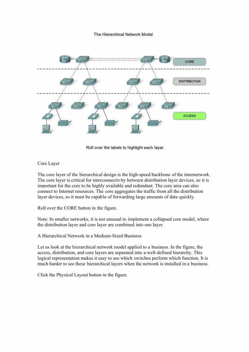
A Hierarchical Network in a Medium-Sized Business
Let us look at the hierarchical network model applied to a business. In the figure, theaccess, distribution, and core layers are separated into a well-defined hierarchy. This
logical representation makes it easy to see which switches perform which function. It is
much harder to see these hierarchical layers when the network is installed in a business.
Click the Physical Layout button in the figure.
8/7/2019 cccna3 cap1
http://slidepdf.com/reader/full/cccna3-cap1 7/50
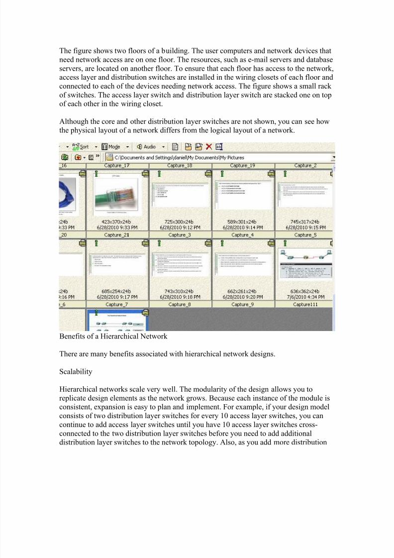
The figure shows two floors of a building. The user computers and network devices that
need network access are on one floor. The resources, such as e-mail servers and database
servers, are located on another floor. To ensure that each floor has access to the network,access layer and distribution switches are installed in the wiring closets of each floor and
connected to each of the devices needing network access. The figure shows a small rack
of switches. The access layer switch and distribution layer switch are stacked one on topof each other in the wiring closet.
Although the core and other distribution layer switches are not shown, you can see howthe physical layout of a network differs from the logical layout of a network.
Benefits of a Hierarchical Network
There are many benefits associated with hierarchical network designs.
Scalability
Hierarchical networks scale very well. The modularity of the design allows you toreplicate design elements as the network grows. Because each instance of the module isconsistent, expansion is easy to plan and implement. For example, if your design model
consists of two distribution layer switches for every 10 access layer switches, you can
continue to add access layer switches until you have 10 access layer switches cross-
connected to the two distribution layer switches before you need to add additionaldistribution layer switches to the network topology. Also, as you add more distribution
8/7/2019 cccna3 cap1
http://slidepdf.com/reader/full/cccna3-cap1 8/50
layer switches to accommodate the load from the access layer switches, you can add
additional core layer switches to handle the additional load on the core.
Redundancy
As a network grows, availability becomes more important. You can dramatically increaseavailability through easy redundant implementations with hierarchical networks. Access
layer switches are connected to two different distribution layer switches to ensure path
redundancy. If one of the distribution layer switches fails, the access layer switch canswitch to the other distribution layer switch. Additionally, distribution layer switches are
connected to two or more core layer switches to ensure path availability if a core switch
fails. The only layer where redundancy is limited is at the access layer. Typically, end
node devices, such as PCs, printers, and IP phones, do not have the ability to connect tomultiple access layer switches for redundancy. If an access layer switch fails, just the
devices connected to that one switch would be affected by the outage. The rest of the
network would continue to function unaffected.
Performance
Communication performance is enhanced by avoiding the transmission of data through
low-performing, intermediary switches. Data is sent through aggregated switch port links
from the access layer to the distribution layer at near wire speed in most cases. The
distribution layer then uses its high performance switching capabilities to forward thetraffic up to the core, where it is routed to its final destination. Because the core and
distribution layers perform their operations at very high speeds, there is less contention
for network bandwidth. As a result, properly designed hierarchical networks can achievenear wire speed between all devices.
Security
Security is improved and easier to manage. Access layer switches can be configured with
various port security options that provide control over which devices are allowed toconnect to the network. You also have the flexibility to use more advanced security
policies at the distribution layer. You may apply access control policies that define which
communication protocols are deployed on your network and where they are permitted to
go. For example, if you want to limit the use of HTTP to a specific user communityconnected at the access layer, you could apply a policy that blocks HTTP traffic at the
distribution layer. Restricting traffic based on higher layer protocols, such as IP and
HTTP, requires that your switches are able to process policies at that layer. Some accesslayer switches support Layer 3 functionality, but it is usually the job of the distribution
layer switches to process Layer 3 data, because they can process it much more efficiently.
Manageability
Manageability is relatively simple on a hierarchical network. Each layer of the
hierarchical design performs specific functions that are consistent throughout that layer.
8/7/2019 cccna3 cap1
http://slidepdf.com/reader/full/cccna3-cap1 9/50
Therefore, if you need to change the functionality of an access layer switch, you could
repeat that change across all access layer switches in the network because they
presumably perform the same functions at their layer. Deployment of new switches isalso simplified because switch configurations can be copied between devices with very
few modifications. Consistency between the switches at each layer allows for rapid
recovery and simplified troubleshooting. In some special situations, there could beconfiguration inconsistencies between devices, so you should ensure that configurations
are well documented so that you can compare them before deployment.
Maintainability
Because hierarchical networks are modular in nature and scale very easily, they are easy
to maintain. With other network topology designs, manageability becomes increasinglycomplicated as the network grows. Also, in some network design models, there is a finite
limit to how large the network can grow before it becomes too complicated and
expensive to maintain. In the hierarchical design model, switch functions are defined at
each layer, making the selection of the correct switch easier. Adding switches to onelayer does not necessarily mean there will not be a bottleneck or other limitation at
another layer. For a full mesh network topology to achieve maximum performance, allswitches need to be high-performance switches, because each switch needs to be capable
of performing all the functions on the network. In the hierarchical model, switch
functions are different at each layer. You can save money by using less expensive access
layer switches at the lowest layer, and spend more on the distribution and core layer switches to achieve high performance on the network.

8/7/2019 cccna3 cap1
http://slidepdf.com/reader/full/cccna3-cap1 10/50
Hierarchical Network Design Principles
Just because a network seems to have a hierarchical design does not mean that the
network is well designed. These simple guidelines will help you differentiate between
well-designed and poorly designed hierarchical networks. This section is not intended to
provide you with all the skills and knowledge you need to design a hierarchical network,but it offers you an opportunity to begin to practice your skills by transforming a flat
network topology into a hierarchical network topology.
Network Diameter
When designing a hierarchical network topology, the first thing to consider is network
diameter. Diameter is usually a measure of distance, but in this case, we are using the
term to measure the number of devices. Network diameter is the number of devices that a
packet has to cross before it reaches its destination. Keeping the network diameter lowensures low and predictable latency between devices.
Roll over the Network Diameter button in the figure.
In the figure, PC1 communicates with PC3. There could be up to six interconnected
switches between PC1 and PC3. In this case, the network diameter is 6. Each switch inthe path introduces some degree of latency. Network device latency is the time spent by a
device as it processes a packet or frame. Each switch has to determine the destination
MAC address of the frame, check its MAC address table, and forward the frame out the
8/7/2019 cccna3 cap1
http://slidepdf.com/reader/full/cccna3-cap1 11/50
appropriate port. Even though that entire process happens in a fraction of a second, the
time adds up when the frame has to cross many switches.
In the three-layer hierarchical model, Layer 2 segmentation at the distribution layer
practically eliminates network diameter as an issue. In a hierarchical network, network
diameter is always going to be a predictable number of hops between the source anddestination devices.
Bandwidth Aggregation
Each layer in the hierarchical network model is a possible candidate for bandwidth
aggregation. Bandwidth aggregation is the practice of considering the specific bandwidth
requirements of each part of the hierarchy. After bandwidth requirements of the network are known, links between specific switches can be aggregated, which is called link
aggregation. Link aggregation allows multiple switch port links to be combined so as to
achieve higher throughput between switches. Cisco has a proprietary link aggregation
technology called EtherChannel, which allows multiple Ethernet links to be consolidated.A discussion of EtherChannel is beyond the scope of this course. To learn more, visit:
http://www.cisco.com/en/US/tech/tk389/tk213/tsd_technology_support_protocol_home.html.
Roll over the Bandwidth Aggregation button in the figure.
In the figure, computers PC1 and PC3 require a significant amount of bandwidth because
they are used for developing weather simulations. The network manager has determined
that the access layer switches S1, S3, and S5 require increased bandwidth. Following upthe hierarchy, these access layer switches connect to the distribution switches D1, D2,
and D4. The distribution switches connect to core layer switches C1 and C2. Notice how
specific links on specific ports in each switch are aggregated. In this way, increasedbandwidth is provided for in a targeted, specific part of the network. Note that in this
figure, aggregated links are indicated by two dotted lines with an oval tying them
together. In other figures, aggregated links are represented by a single, dotted line with anoval.
Redundancy
Redundancy is one part of creating a highly available network. Redundancy can be
provided in a number of ways. For example, you can double up the network connections
between devices, or you can double the devices themselves. This chapter explores how toemploy redundant network paths between switches. A discussion on doubling up network
devices and employing special network protocols to ensure high availability is beyond the
scope of this course. For an interesting discussion on high availability, visit:http://www.cisco.com/en/US/products/ps6550/products_ios_technology_home.html.
Implementing redundant links can be expensive. Imagine if every switch in each layer of
the network hierarchy had a connection to every switch at the next layer. It is unlikely
8/7/2019 cccna3 cap1
http://slidepdf.com/reader/full/cccna3-cap1 12/50
that you will be able to implement redundancy at the access layer because of the cost and
limited features in the end devices, but you can build redundancy into the distribution and
core layers of the network.
Roll over the Redundant Links button in the figure.
In the figure, redundant links are shown at the distribution layer and core layer. At the
distribution layer, there are two distribution layer switches, the minimum required to
support redundancy at this layer. The access layer switches, S1, S3, S4, and S6, are cross-connected to the distribution layer switches. This protects your network if one of the
distribution switches fails. In case of a failure, the access layer switch adjusts its
transmission path and forwards the traffic through the other distribution switch.
Some network failure scenarios can never be prevented, for example, if the power goes
out in the entire city, or the entire building is demolished because of an earthquake.
Redundancy does not attempt to address these types of disasters.
Start at the Access Layer
Imagine that a new network design is required. Design requirements, such as the level of
performance or redundancy necessary, are determined by the business goals of the
organization. Once the design requirements are documented, the designer can begin
selecting the equipment and infrastructure to implement the design.
When you start the equipment selection at the access layer, you can ensure that you
accommodate all network devices needing access to the network. After you have all enddevices accounted for, you have a better idea of how many access layer switches you
need. The number of access layer switches, and the estimated traffic that each generates,
helps you to determine how many distribution layer switches are required to achieve theperformance and redundancy needed for the network. After you have determined the
number of distribution layer switches, you can identify how many core switches are
required to maintain the performance of the network.
A thorough discussion on how to determine which switch to select based on traffic flow
analysis and how many core switches are required to maintain performance is beyond the
scope of this course. For a good introduction to network design, read this book that isavailable from Ciscopress.com: Top-Down Network Design, by Priscilla Oppenheimer
(2004).
8/7/2019 cccna3 cap1
http://slidepdf.com/reader/full/cccna3-cap1 13/50
Small and medium-sized businesses are embracing the idea of running voice and videoservices on their data networks. Let us look at how voice and video over IP (VoIP) affect
a hierarchical network.
Legacy Equipment
Convergence is the process of combining voice and video communications on a data
network. Converged networks have existed for a while now, but were only feasible inlarge enterprise organizations because of the network infrastructure requirements and
complex management that was involved to make them work seamlessly. There were high
network costs associated with convergence because more expensive switch hardware wasrequired to support the additional bandwidth requirements. Converged networks also
required extensive management in relation to Quality of Service (QoS), because voice
and video data traffic needed to be classified and prioritized on the network. Fewindividuals had the expertise in voice, video, and data networks to make convergence
feasible and functional. In addition, legacy equipment hinders the process. The figure
shows a legacy telephone company switch. Most telephone companies today have made
the transition to digital-based switches. However, there are many offices that still useanalog phones, so they still have existing analog telephone wiring closets. Because
analog phones have not yet been replaced, you will also see equipment that has to support
both legacy PBX telephone systems and IP-based phones. This sort of equipment willslowly be migrated to modern IP-based phone switches.
Click Advanced Technology button in the figure.
8/7/2019 cccna3 cap1
http://slidepdf.com/reader/full/cccna3-cap1 14/50
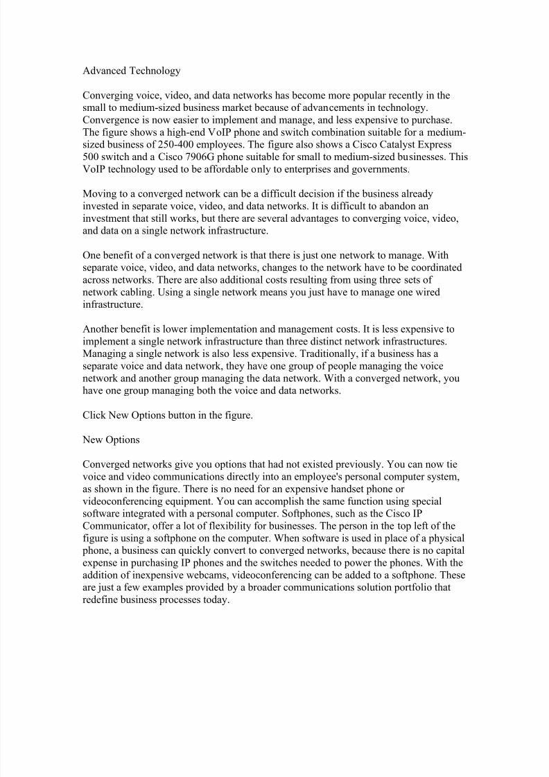
Advanced Technology
Converging voice, video, and data networks has become more popular recently in thesmall to medium-sized business market because of advancements in technology.
Convergence is now easier to implement and manage, and less expensive to purchase.
The figure shows a high-end VoIP phone and switch combination suitable for a medium-sized business of 250-400 employees. The figure also shows a Cisco Catalyst Express
500 switch and a Cisco 7906G phone suitable for small to medium-sized businesses. This
VoIP technology used to be affordable only to enterprises and governments.
Moving to a converged network can be a difficult decision if the business already
invested in separate voice, video, and data networks. It is difficult to abandon an
investment that still works, but there are several advantages to converging voice, video,and data on a single network infrastructure.
One benefit of a converged network is that there is just one network to manage. With
separate voice, video, and data networks, changes to the network have to be coordinatedacross networks. There are also additional costs resulting from using three sets of
network cabling. Using a single network means you just have to manage one wiredinfrastructure.
Another benefit is lower implementation and management costs. It is less expensive to
implement a single network infrastructure than three distinct network infrastructures.Managing a single network is also less expensive. Traditionally, if a business has a
separate voice and data network, they have one group of people managing the voice
network and another group managing the data network. With a converged network, youhave one group managing both the voice and data networks.
Click New Options button in the figure.
New Options
Converged networks give you options that had not existed previously. You can now tie
voice and video communications directly into an employee's personal computer system,
as shown in the figure. There is no need for an expensive handset phone or
videoconferencing equipment. You can accomplish the same function using specialsoftware integrated with a personal computer. Softphones, such as the Cisco IP
Communicator, offer a lot of flexibility for businesses. The person in the top left of the
figure is using a softphone on the computer. When software is used in place of a physicalphone, a business can quickly convert to converged networks, because there is no capital
expense in purchasing IP phones and the switches needed to power the phones. With the
addition of inexpensive webcams, videoconferencing can be added to a softphone. Theseare just a few examples provided by a broader communications solution portfolio that
redefine business processes today.
8/7/2019 cccna3 cap1
http://slidepdf.com/reader/full/cccna3-cap1 15/50
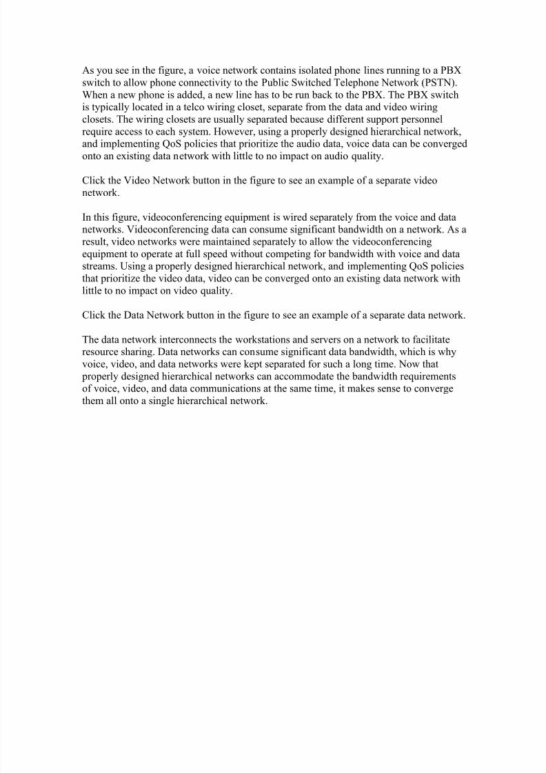
Separate Voice, Video and Data Networks
8/7/2019 cccna3 cap1
http://slidepdf.com/reader/full/cccna3-cap1 16/50
As you see in the figure, a voice network contains isolated phone lines running to a PBX
switch to allow phone connectivity to the Public Switched Telephone Network (PSTN).
When a new phone is added, a new line has to be run back to the PBX. The PBX switchis typically located in a telco wiring closet, separate from the data and video wiring
closets. The wiring closets are usually separated because different support personnel
require access to each system. However, using a properly designed hierarchical network,and implementing QoS policies that prioritize the audio data, voice data can be converged
onto an existing data network with little to no impact on audio quality.
Click the Video Network button in the figure to see an example of a separate video
network.
In this figure, videoconferencing equipment is wired separately from the voice and datanetworks. Videoconferencing data can consume significant bandwidth on a network. As a
result, video networks were maintained separately to allow the videoconferencing
equipment to operate at full speed without competing for bandwidth with voice and data
streams. Using a properly designed hierarchical network, and implementing QoS policiesthat prioritize the video data, video can be converged onto an existing data network with
little to no impact on video quality.
Click the Data Network button in the figure to see an example of a separate data network.
The data network interconnects the workstations and servers on a network to facilitateresource sharing. Data networks can consume significant data bandwidth, which is why
voice, video, and data networks were kept separated for such a long time. Now that
properly designed hierarchical networks can accommodate the bandwidth requirementsof voice, video, and data communications at the same time, it makes sense to converge
them all onto a single hierarchical network.
8/7/2019 cccna3 cap1
http://slidepdf.com/reader/full/cccna3-cap1 17/50
Traffic Flow Analysis
8/7/2019 cccna3 cap1
http://slidepdf.com/reader/full/cccna3-cap1 18/50
To select the appropriate switch for a layer in a hierarchical network, you need to have
specifications that detail the target traffic flows, user communities, data servers, and data
storage servers.
Companies need a network that can meet evolving requirements. A business may start
with a few PCs interconnected so that they can share data. As the business adds moreemployees, devices, such as PCs, printers, and servers, are added to the network.
Accompanying the new devices is an increase in network traffic. Some companies are
replacing their existing telephone systems with converged VoIP phone systems, whichadds additional traffic.
When selecting switch hardware, determine which switches are needed in the core,
distribution, and access layers to accommodate the bandwidth requirements of your network. Your plan should take into account future bandwidth requirements. Purchase the
appropriate Cisco switch hardware to accommodate both current needs as well as future
needs. To help you more accurately choose appropriate switches, perform and record
traffic flow analyses on a regular basis.
Traffic Flow Analysis
Traffic flow analysis is the process of measuring the bandwidth usage on a network and
analyzing the data for the purpose of performance tuning, capacity planning, and making
hardware improvement decisions. Traffic flow analysis is done using traffic flow analysissoftware. Although there is no precise definition of network traffic flow, for the purposes
of traffic flow analysis we can say that network traffic is the amount of data sent through
a network for a given period of time. All network data contributes to the traffic,regardless of its purpose or source. Analyzing the various traffic sources and their impact
on the network, allows you to more accurately tune and upgrade the network to achieve
the best possible performance.
Traffic flow data can be used to help determine just how long you can continue using
existing network hardware before it makes sense to upgrade to accommodate additionalbandwidth requirements. When you are making your decisions about which hardware to
purchase, you should consider port densities and switch forwarding rates to ensure
adequate growth capability. Port density and forwarding rates are explained later in this
chapter.
There are many ways to monitor traffic flow on a network. You can manually monitor
individual switch ports to get the bandwidth utilization over time. When analyzing thetraffic flow data, you want to determine future traffic flow requirements based on the
capacity at certain times of the day and where most of the data is generated and sent.
However, to obtain accurate results, you need to record enough data. Manual recording of traffic data is a tedious process that requires a lot of time and diligence. Fortunately, there
are some automated solutions.
Analysis Tools
8/7/2019 cccna3 cap1
http://slidepdf.com/reader/full/cccna3-cap1 19/50
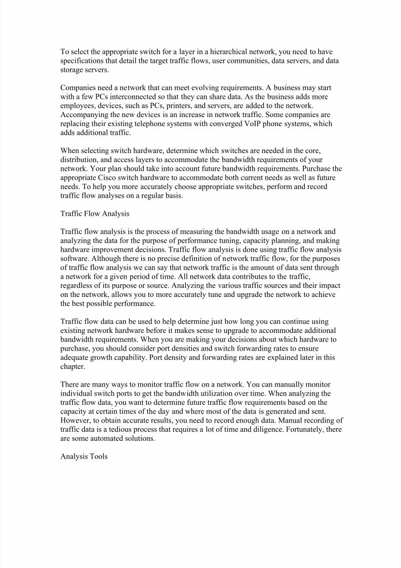
Many traffic flow analysis tools that automatically record traffic flow data to a database
and perform a trend analysis are available. In larger networks, software collectionsolutions are the only effective method for performing traffic flow analysis. The figure
displays sample output from Solarwinds Orion 8.1 NetFlow Analysis, which monitors
traffic flow on a network. While the software is collecting data, you can see just howevery interface is performing at any given point in time on the network. Using the
included charts, you can identify traffic flow problems visually. This is much easier than
having to interpret the numbers in a column of traffic flow data.
For a list of some commercial traffic flow collection and analysis tools, visit
http://www.cisco.com/warp/public/732/Tech/nmp/netflow/partners/commercial/index.sht
ml.
For a list of some freeware traffic flow collection and analysis tools, visit
http://www.cisco.com/warp/public/732/Tech/nmp/netflow/partners/freeware/index.shtml.
User Communities Analysis
User community analysis is the process of identifying various groupings of users and
their impact on network performance. The way users are grouped affects issues related toport density and traffic flow, which, in turn, influences the selection of network switches.
Port density is explained later in this chapter.
8/7/2019 cccna3 cap1
http://slidepdf.com/reader/full/cccna3-cap1 20/50
In a typical office building, end users are grouped according to their job function, because
they require similar access to resources and applications. You may find the Human
Resource (HR) department located on one floor of an office building, while Finance islocated on another floor. Each department has a different number of users and application
needs, and requires access to different data resources available through the network. For
example, when selecting switches for the wiring closets of the HR and Financedepartments, you would choose a switch that had enough ports to meet the department
needs and was powerful enough to accommodate the traffic requirements for all the
devices on that floor. Additionally, a good network design plan factors in the growth of each department to ensure that there are enough open switch ports that can utilized before
the next planned upgrade to the network.
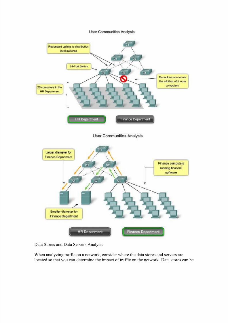
As shown in the figure, the HR department requires 20 workstations for its 20 users. Thattranslates to 20 switch ports needed to connect the workstations to the network. If you
were to select an appropriate access layer switch to accommodate the HR department,
you would probably choose a 24 port switch, which has enough ports to accommodate
the 20 workstations and the uplinks to the distribution layer switches.
Future Growth
But this plan does not account for future growth. Consider what will happen if the HR
department grows by five employees. A solid network plan includes the rate of personnel
growth over the past five years to be able to anticipate the future growth. With that inmind, you would want to purchase a switch that can accommodate more than 24 ports,
such as stackable or modular switches that can scale.
As well as looking at the number of devices on a given switch in a network, you should
investigate the network traffic generated by end-user applications. Some user
communities use applications that generate a lot of network traffic, while other user communities do not. By measuring the network traffic generated for all applications in
use by different user communities, and determining the location of the data source, you
can identify the effect of adding more users to that community.
A workgroup-sized user community in a small business is supported by a couple of
switches and typically connected to the same switch as the server. In medium-sized
businesses or enterprises, user communities are supported by many switches. Theresources that medium-sized business or enterprise user communities need could be
located in geographically separate areas. Consequently, the location of the user
communities influences where data stores and server farms are located.
Click the Finance Department button in the figure.
If the Finance users are using a network-intensive application that exchanges data with a
specific server on the network, it may make sense to locate the Finance user community
close to that server. By locating users close to their servers and data stores, you can

8/7/2019 cccna3 cap1
http://slidepdf.com/reader/full/cccna3-cap1 21/50
reduce the network diameter for their communications, thereby reducing the impact of
their traffic across the rest of the network.
One complication of analyzing application usage by user communities is that usage is not
always bound by department or physical location. You may have to analyze the impact of
the application across many network switches to determine its overall impact.
8/7/2019 cccna3 cap1
http://slidepdf.com/reader/full/cccna3-cap1 22/50
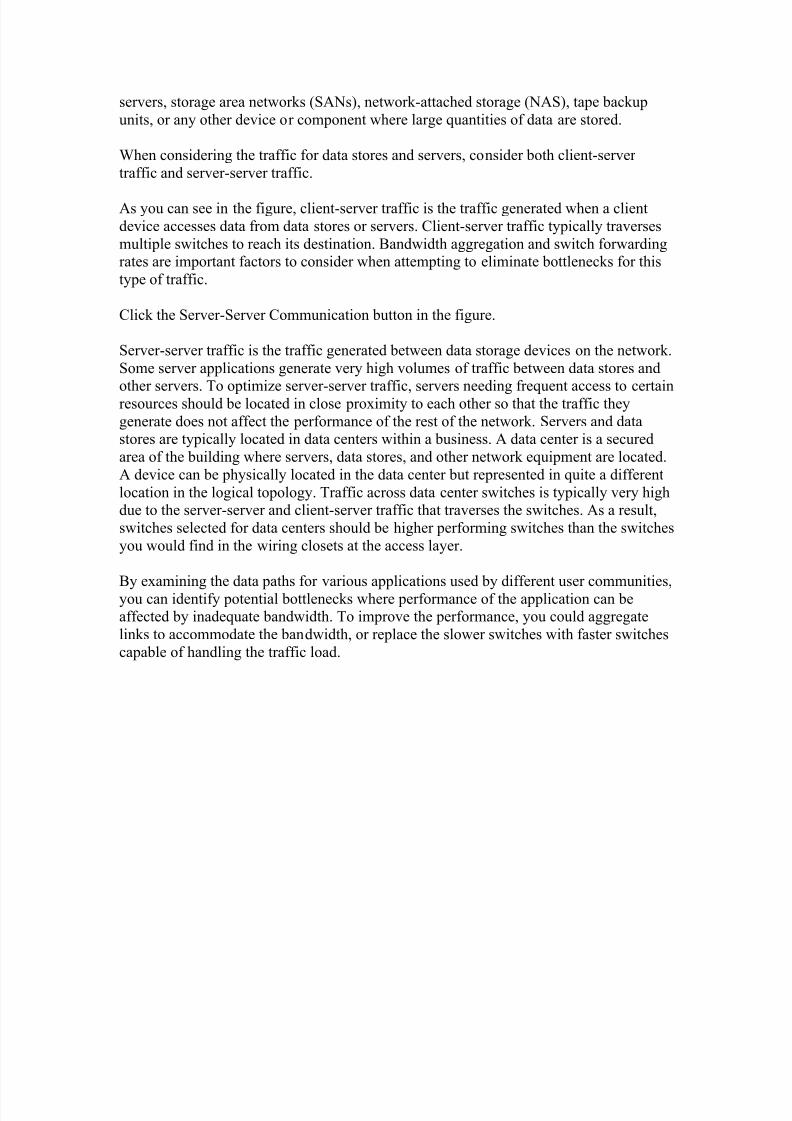
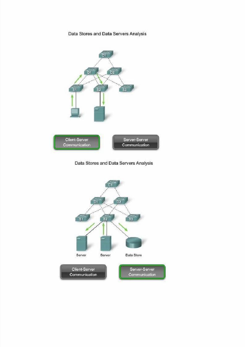
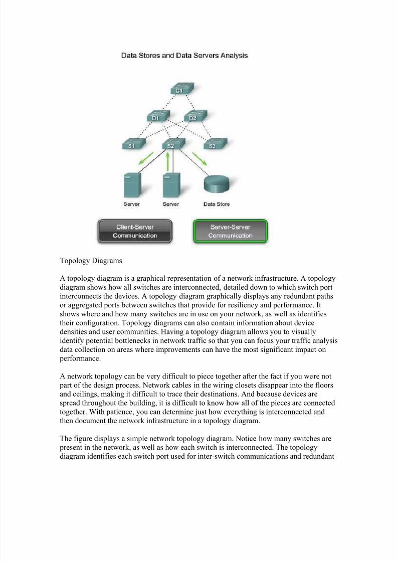
Data Stores and Data Servers Analysis
When analyzing traffic on a network, consider where the data stores and servers are
located so that you can determine the impact of traffic on the network. Data stores can be
8/7/2019 cccna3 cap1
http://slidepdf.com/reader/full/cccna3-cap1 23/50
servers, storage area networks (SANs), network-attached storage (NAS), tape backup
units, or any other device or component where large quantities of data are stored.
When considering the traffic for data stores and servers, consider both client-server
traffic and server-server traffic.
As you can see in the figure, client-server traffic is the traffic generated when a client
device accesses data from data stores or servers. Client-server traffic typically traverses
multiple switches to reach its destination. Bandwidth aggregation and switch forwardingrates are important factors to consider when attempting to eliminate bottlenecks for this
type of traffic.
Click the Server-Server Communication button in the figure.
Server-server traffic is the traffic generated between data storage devices on the network.
Some server applications generate very high volumes of traffic between data stores and
other servers. To optimize server-server traffic, servers needing frequent access to certainresources should be located in close proximity to each other so that the traffic they
generate does not affect the performance of the rest of the network. Servers and datastores are typically located in data centers within a business. A data center is a secured
area of the building where servers, data stores, and other network equipment are located.
A device can be physically located in the data center but represented in quite a different
location in the logical topology. Traffic across data center switches is typically very highdue to the server-server and client-server traffic that traverses the switches. As a result,
switches selected for data centers should be higher performing switches than the switches
you would find in the wiring closets at the access layer.
By examining the data paths for various applications used by different user communities,
you can identify potential bottlenecks where performance of the application can beaffected by inadequate bandwidth. To improve the performance, you could aggregate
links to accommodate the bandwidth, or replace the slower switches with faster switches
capable of handling the traffic load.
8/7/2019 cccna3 cap1
http://slidepdf.com/reader/full/cccna3-cap1 24/50
8/7/2019 cccna3 cap1
http://slidepdf.com/reader/full/cccna3-cap1 25/50
Topology Diagrams
A topology diagram is a graphical representation of a network infrastructure. A topology
diagram shows how all switches are interconnected, detailed down to which switch port
interconnects the devices. A topology diagram graphically displays any redundant pathsor aggregated ports between switches that provide for resiliency and performance. It
shows where and how many switches are in use on your network, as well as identifies
their configuration. Topology diagrams can also contain information about devicedensities and user communities. Having a topology diagram allows you to visually
identify potential bottlenecks in network traffic so that you can focus your traffic analysis
data collection on areas where improvements can have the most significant impact onperformance.
A network topology can be very difficult to piece together after the fact if you were not
part of the design process. Network cables in the wiring closets disappear into the floors
and ceilings, making it difficult to trace their destinations. And because devices arespread throughout the building, it is difficult to know how all of the pieces are connected
together. With patience, you can determine just how everything is interconnected andthen document the network infrastructure in a topology diagram.
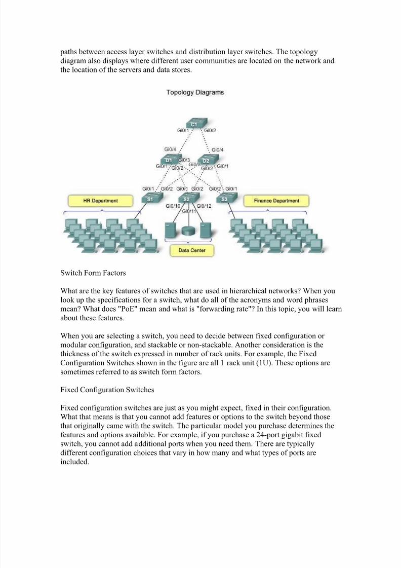
The figure displays a simple network topology diagram. Notice how many switches arepresent in the network, as well as how each switch is interconnected. The topology
diagram identifies each switch port used for inter-switch communications and redundant
8/7/2019 cccna3 cap1
http://slidepdf.com/reader/full/cccna3-cap1 26/50
paths between access layer switches and distribution layer switches. The topology
diagram also displays where different user communities are located on the network and
the location of the servers and data stores.
Switch Form Factors
What are the key features of switches that are used in hierarchical networks? When you
look up the specifications for a switch, what do all of the acronyms and word phrasesmean? What does "PoE" mean and what is "forwarding rate"? In this topic, you will learn
about these features.
When you are selecting a switch, you need to decide between fixed configuration or
modular configuration, and stackable or non-stackable. Another consideration is thethickness of the switch expressed in number of rack units. For example, the Fixed
Configuration Switches shown in the figure are all 1 rack unit (1U). These options are
sometimes referred to as switch form factors.
Fixed Configuration Switches
Fixed configuration switches are just as you might expect, fixed in their configuration.What that means is that you cannot add features or options to the switch beyond those
that originally came with the switch. The particular model you purchase determines the
features and options available. For example, if you purchase a 24-port gigabit fixedswitch, you cannot add additional ports when you need them. There are typically
different configuration choices that vary in how many and what types of ports are
included.
8/7/2019 cccna3 cap1
http://slidepdf.com/reader/full/cccna3-cap1 27/50
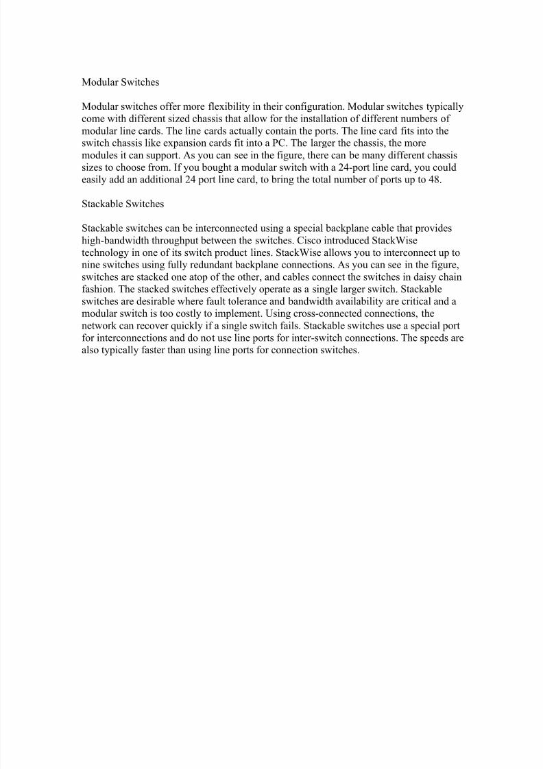
Modular Switches
Modular switches offer more flexibility in their configuration. Modular switches typically
come with different sized chassis that allow for the installation of different numbers of
modular line cards. The line cards actually contain the ports. The line card fits into theswitch chassis like expansion cards fit into a PC. The larger the chassis, the more
modules it can support. As you can see in the figure, there can be many different chassis
sizes to choose from. If you bought a modular switch with a 24-port line card, you couldeasily add an additional 24 port line card, to bring the total number of ports up to 48.
Stackable Switches
Stackable switches can be interconnected using a special backplane cable that provides
high-bandwidth throughput between the switches. Cisco introduced StackWise
technology in one of its switch product lines. StackWise allows you to interconnect up to
nine switches using fully redundant backplane connections. As you can see in the figure,switches are stacked one atop of the other, and cables connect the switches in daisy chain
fashion. The stacked switches effectively operate as a single larger switch. Stackableswitches are desirable where fault tolerance and bandwidth availability are critical and a
modular switch is too costly to implement. Using cross-connected connections, the
network can recover quickly if a single switch fails. Stackable switches use a special port
for interconnections and do not use line ports for inter-switch connections. The speeds arealso typically faster than using line ports for connection switches.
8/7/2019 cccna3 cap1
http://slidepdf.com/reader/full/cccna3-cap1 28/50
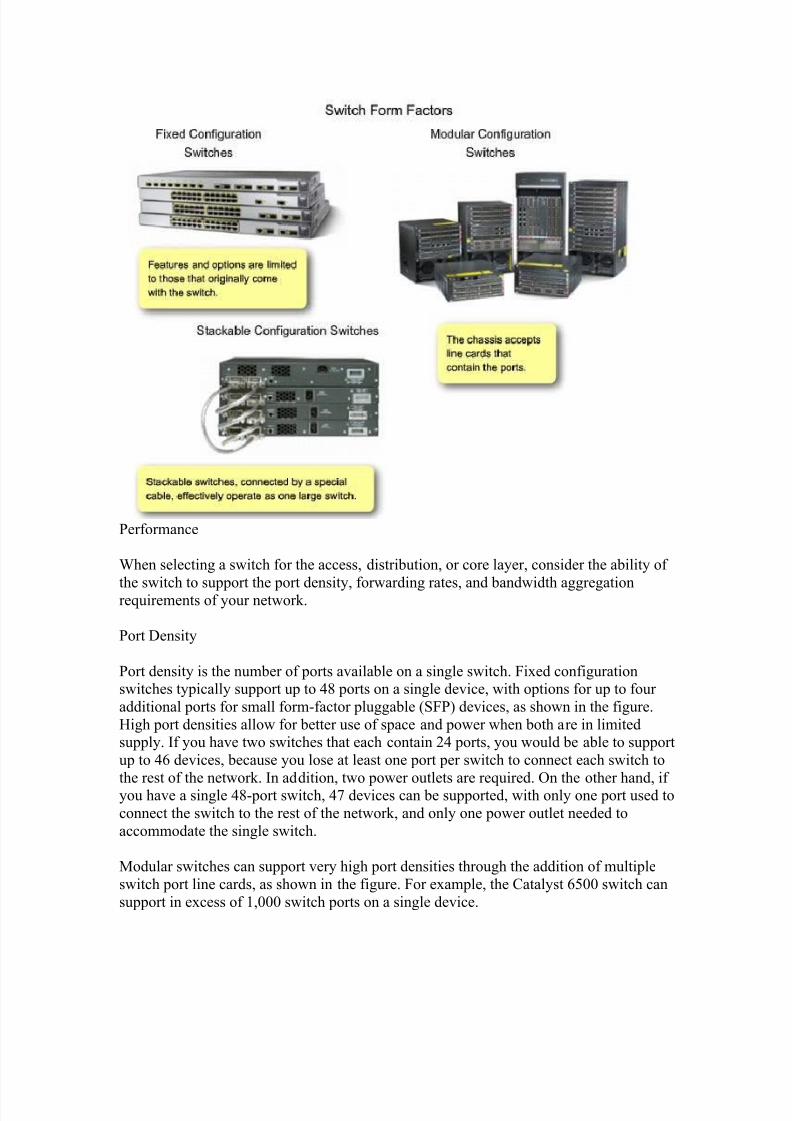
Performance
When selecting a switch for the access, distribution, or core layer, consider the ability of
the switch to support the port density, forwarding rates, and bandwidth aggregationrequirements of your network.
Port Density
Port density is the number of ports available on a single switch. Fixed configurationswitches typically support up to 48 ports on a single device, with options for up to four
additional ports for small form-factor pluggable (SFP) devices, as shown in the figure.
High port densities allow for better use of space and power when both are in limitedsupply. If you have two switches that each contain 24 ports, you would be able to support
up to 46 devices, because you lose at least one port per switch to connect each switch to
the rest of the network. In addition, two power outlets are required. On the other hand, if you have a single 48-port switch, 47 devices can be supported, with only one port used to
connect the switch to the rest of the network, and only one power outlet needed to
accommodate the single switch.
Modular switches can support very high port densities through the addition of multiple
switch port line cards, as shown in the figure. For example, the Catalyst 6500 switch can
support in excess of 1,000 switch ports on a single device.
8/7/2019 cccna3 cap1
http://slidepdf.com/reader/full/cccna3-cap1 29/50
Large enterprise networks that support many thousands of network devices require high
density, modular switches to make the best use of space and power. Without using ahigh-density modular switch, the network would need many fixed configuration switches
to accommodate the number of devices that need network access. This approach can
consume many power outlets and a lot of closet space.
You must also address the issue of uplink bottlenecks. A series of fixed configuration
switches may consume many additional ports for bandwidth aggregation betweenswitches for the purpose of achieving target performance. With a single modular switch,
bandwidth aggregation is less of an issue because the backplane of the chassis can
provide the necessary bandwidth to accommodate the devices connected to the switch
port line cards.
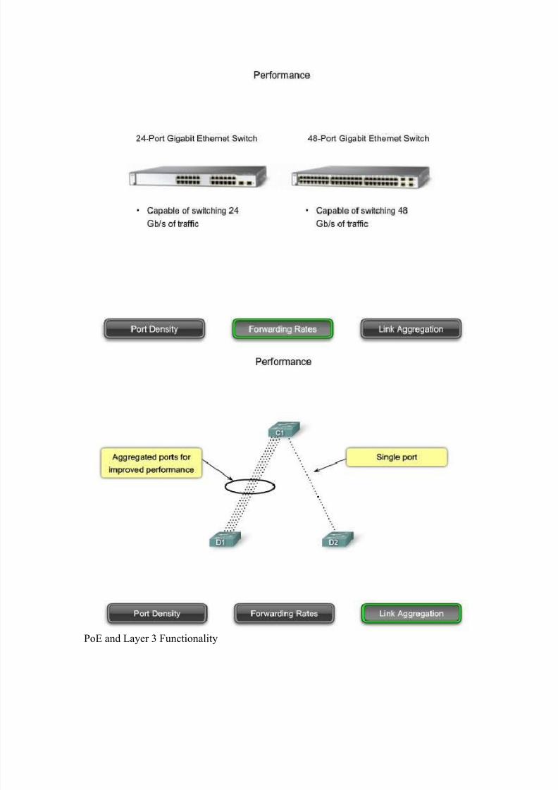
Forwarding Rates
Click Forwarding Rates button in the figure to see an example of forwarding rates onswitches with different port densities.
Forwarding rates define the processing capabilities of a switch by rating how much data
the switch can process per second. Switch product lines are classified by forwarding
rates. Entry-layer switches have lower forwarding rates than enterprise-layer switches.
Forwarding rates are important to consider when selecting a switch. If the switchforwarding rate is too low, it cannot accommodate full wire-speed communication across
all of its switch ports. Wire speed is the data rate that each port on the switch is capable
of attaining, either 100 Mb/s Fast Ethernet or 1000 Mb/s Gigabit Ethernet. For example, a48-port gigabit switch operating at full wire speed generates 48 Gb/s of traffic. If the
switch only supports a forwarding rate of 32 Gb/s, it cannot run at full wire speed across
all ports simultaneously. Fortunately, access layer switches typically do not need tooperate at full wire speed because they are physically limited by their uplinks to the
distribution layer. This allows you to use less expensive, lower performing switches at
the access layer, and use the more expensive, higher performing switches at thedistribution and core layers, where the forwarding rate makes a bigger difference.
Link Aggregation
Click the Link Aggregation button in the figure.
As part of bandwidth aggregation, you should determine if there are enough ports on aswitch to aggregate to support the required bandwidth. For example, consider a Gigabit
Ethernet port, which carries up to 1 Gb/s of traffic. If you have a 24-port switch, with all
ports capable of running at gigabit speeds, you could generate up to 24 Gb/s of network traffic. If the switch is connected to the rest of the network by a single network cable, it
can only forward 1 Gb/s of the data to the rest of the network. Due to the contention for
bandwidth, the data would forward more slowly. That results in 1/24th wire speed
available to each of the 24 devices connected to the switch. Wire speed describes the
8/7/2019 cccna3 cap1
http://slidepdf.com/reader/full/cccna3-cap1 30/50
theoretical maximum data transmission rate of a connection. For example, the wire speed
of an Ethernet connection is dependent on the physical and electrical properties of the
cable, combined with the lowest layer of the connection protocols.
Link aggregation helps to reduce these bottlenecks of traffic by allowing up to eight
switch ports to be bound together for data communications, providing up to 8 Gb/s of data throughput when Gigabit Ethernet ports are used. With the addition of multiple 10
Gigabit Ethernet (10GbE) uplinks on some enterprise-layer switches, very high
throughput rates can be achieved. Cisco uses the term EtherChannel when describingaggregated switch ports.
As you can see in the figure, four separate ports on switches C1 and D1 are used to create
a 4-port EtherChannel. EtherChannel technology allows a group of physical Ethernetlinks to create one logical Ethernet link for the purpose of providing fault tolerance and
high-speed links between switches, routers, and servers. In this example, there is four
times the throughput when compared to the single port connection between switches C1
and D2.
8/7/2019 cccna3 cap1
http://slidepdf.com/reader/full/cccna3-cap1 31/50
PoE and Layer 3 Functionality

8/7/2019 cccna3 cap1
http://slidepdf.com/reader/full/cccna3-cap1 32/50
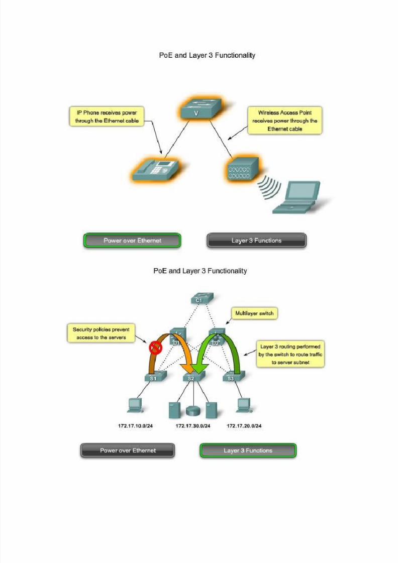
Two other characteristics you want to consider when selecting a switch are Power over
Ethernet (PoE) and Layer 3 functionality.
Power over Ethernet
Power over Ethernet (PoE) allows the switch to deliver power to a device over the
existing Ethernet cabling. As you can see in the figure, this feature can be used by IP
phones and some wireless access points. PoE allows you more flexibility when installingwireless access points and IP phones because you can install them anywhere you can run
an Ethernet cable. You do not need to consider how to run ordinary power to the device.
You should only select a switch that supports PoE if you are actually going to take
advantage of the feature, because it adds considerable cost to the switch.
Click the switch icon to see PoE ports.
Click the phone icon to see the phone ports.
Click the wireless access point icon to see its ports.
Layer 3 Functions
Click the Layer 3 Functions button in the figure to see some Layer 3 functions that can beprovided by switches in a hierarchical network.
Typically, switches operate at Layer 2 of the OSI reference model where they dealprimarily with the MAC addresses of devices connected to switch ports. Layer 3 switches
offer advanced functionality. Layer 3 switches are also known as multilayer switches.
8/7/2019 cccna3 cap1
http://slidepdf.com/reader/full/cccna3-cap1 33/50
8/7/2019 cccna3 cap1
http://slidepdf.com/reader/full/cccna3-cap1 34/50
Access Layer Switch Features
Now that you know which factors to consider when choosing a switch, let us examinewhich features are required at each layer in a hierarchical network. You will then be able
to match the switch specification with its ability to function as an access, distribution, or
core layer switch.
Access layer switches facilitate the connection of end node devices to the network. For
this reason, they need to support features such as port security, VLANs, FastEthernet/Gigabit Ethernet, PoE, and link aggregation.
Port security allows the switch to decide how many or what specific devices are allowed
to connect to the switch. All Cisco switches support port layer security. Port security isapplied at the access layer. Consequently, it is an important first line of defense for a
network. You will learn about port security in Chapter 2.
VLANs are an important component of a converged network. Voice traffic is typicallygiven a separate VLAN. In this way, voice traffic can be supported with more bandwidth,
more redundant connections, and improved security. Access layer switches allow you toset the VLANs for the end node devices on your network.
Port speed is also a characteristic you need to consider for your access layer switches.
Depending on the performance requirements for your network, you must choose betweenFast Ethernet and Gigabit Ethernet switch ports. Fast Ethernet allows up to 100 Mb/s of
traffic per switch port. Fast Ethernet is adequate for IP telephony and data traffic on most
business networks, however, performance is slower than Gigabit Ethernet ports. GigabitEthernet allows up to 1000 Mb/s of traffic per switch port. Most modern devices, such as
workstations, notebooks, and IP phones, support Gigabit Ethernet. This allows for much
more efficient data transfers, enabling users to be more productive. Gigabit Ethernet doeshave a drawback-switches supporting Gigabit Ethernet are more expensive.
Another feature requirement for some access layer switches is PoE. PoE dramaticallyincreases the overall price of the switch across all Cisco Catalyst switch product lines, so
it should only be considered when voice convergence is required or wireless access
points are being implemented, and power is difficult or expensive to run to the desired
location.
Link aggregation is another feature that is common to most access layer switches. Link
aggregation allows the switch to use multiple links simultaneously. Access layer switchestake advantage of link aggregation when aggregating bandwidth up to distribution layer
switches.
Because the uplink connection between the access layer switch and the distribution layer
switch is typically the bottleneck in communication, the internal forwarding rate of
access layer switches does not need to be as high as the link between the distribution and
access layer switches. Characteristics such as the internal forwarding rate are less of a
8/7/2019 cccna3 cap1
http://slidepdf.com/reader/full/cccna3-cap1 35/50
concern for access layer switches because they only handle traffic from the end devices
and forward it to the distribution layer switches.
In a converged network supporting voice, video and data network traffic, access layer
switches need to support QoS to maintain the prioritization of traffic. Cisco IP phones are
types of equipment that are found at the access layer. When a Cisco IP phone is pluggedinto an access layer switch port configured to support voice traffic, that switch port tells
the IP phone how to send its voice traffic. QoS needs to be enabled on access layer
switches so that voice traffic the IP phone has priority over, for example, data traffic.
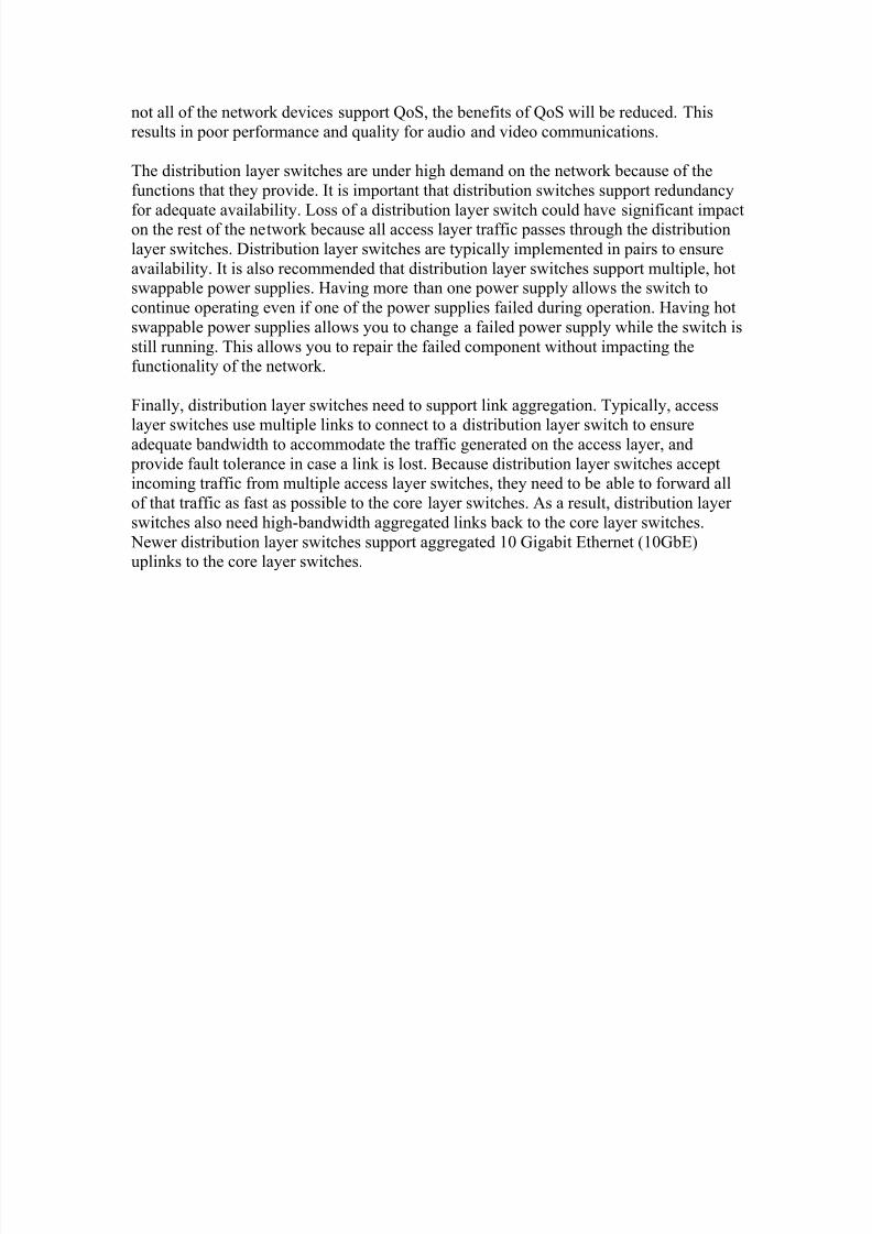
Distribution Layer Switch Features
Distribution layer switches have a very important role on the network. They collect thedata from all the access layer switches and forward it to the core layer switches. As you
will learn later in this course, traffic that is generated at Layer 2 on a switched network
needs to be managed, or segmented into VLANs, so it does not needlessly consume
bandwidth throughout the network. Distribution layer switches provides the inter-VLANrouting functions so that one VLAN can communicate with another on the network. This
routing typically takes place at the distribution layer because distribution layer switcheshave higher processing capabilities than the access layer switches. Distribution layer
switches alleviate the core switches from needing to perform that task since the core is
busy handling the forwarding of very high volumes of traffic. Because inter-VLAN
routing is performed at the distribution layer, the switches at this layer need to supportLayer 3 functions.
Security Policies
Another reason why Layer 3 functionality is required for distribution layer switches is
because of the advanced security policies that can be applied to network traffic. Accesslists are used to control how traffic flows through the network. An Access Control List
(ACL) allows the switch to prevent certain types of traffic and permit others. ACLs also
allow you to control which network devices can communicate on the network. UsingACLs is processing-intensive because the switch needs to inspect every packet and see if
it matches one of the ACL rules defined on the switch. This inspection is performed at
the distribution layer, because the switches at this layer typically have the processing
capability to handle the additional load, and it also simplifies the use of ACLs. Instead of using ACLs for every access layer switch in the network, they are defined on the fewer
distribution layer switches, making management of the ACLs much easier.
Quality of Service
The distribution layer switches also need to support QoS to maintain the prioritization of traffic coming from the access layer switches that have implemented QoS. Priority
policies ensure that audio and video communications are guaranteed adequate bandwidth
to maintain an acceptable quality of service. To maintain the priority of the voice data
throughout the network, all of the switches that forward voice data must support QoS; if
8/7/2019 cccna3 cap1
http://slidepdf.com/reader/full/cccna3-cap1 36/50
not all of the network devices support QoS, the benefits of QoS will be reduced. This
results in poor performance and quality for audio and video communications.
The distribution layer switches are under high demand on the network because of the
functions that they provide. It is important that distribution switches support redundancy
for adequate availability. Loss of a distribution layer switch could have significant impacton the rest of the network because all access layer traffic passes through the distribution
layer switches. Distribution layer switches are typically implemented in pairs to ensure
availability. It is also recommended that distribution layer switches support multiple, hotswappable power supplies. Having more than one power supply allows the switch to
continue operating even if one of the power supplies failed during operation. Having hot
swappable power supplies allows you to change a failed power supply while the switch is
still running. This allows you to repair the failed component without impacting thefunctionality of the network.
Finally, distribution layer switches need to support link aggregation. Typically, access
layer switches use multiple links to connect to a distribution layer switch to ensureadequate bandwidth to accommodate the traffic generated on the access layer, and
provide fault tolerance in case a link is lost. Because distribution layer switches acceptincoming traffic from multiple access layer switches, they need to be able to forward all
of that traffic as fast as possible to the core layer switches. As a result, distribution layer
switches also need high-bandwidth aggregated links back to the core layer switches.
Newer distribution layer switches support aggregated 10 Gigabit Ethernet (10GbE)uplinks to the core layer switches.
8/7/2019 cccna3 cap1
http://slidepdf.com/reader/full/cccna3-cap1 37/50
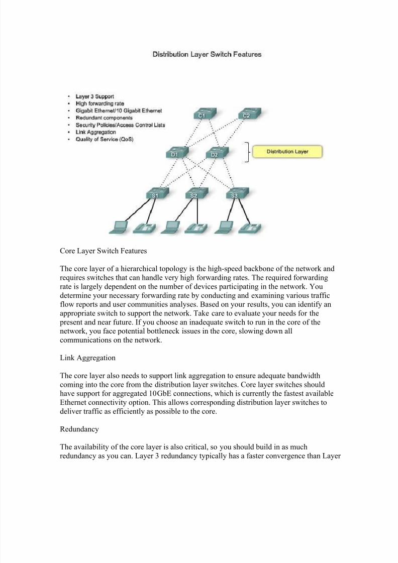
Core Layer Switch Features
The core layer of a hierarchical topology is the high-speed backbone of the network and
requires switches that can handle very high forwarding rates. The required forwarding
rate is largely dependent on the number of devices participating in the network. You
determine your necessary forwarding rate by conducting and examining various trafficflow reports and user communities analyses. Based on your results, you can identify an
appropriate switch to support the network. Take care to evaluate your needs for the
present and near future. If you choose an inadequate switch to run in the core of thenetwork, you face potential bottleneck issues in the core, slowing down all
communications on the network.
Link Aggregation
The core layer also needs to support link aggregation to ensure adequate bandwidth
coming into the core from the distribution layer switches. Core layer switches should
have support for aggregated 10GbE connections, which is currently the fastest availableEthernet connectivity option. This allows corresponding distribution layer switches to
deliver traffic as efficiently as possible to the core.
Redundancy
The availability of the core layer is also critical, so you should build in as much
redundancy as you can. Layer 3 redundancy typically has a faster convergence than Layer
8/7/2019 cccna3 cap1
http://slidepdf.com/reader/full/cccna3-cap1 38/50
2 redundancy in the event of hardware failure. Convergence in this context refers to the
time it takes for the network to adapt to a change, not to be confused with a converged
network that supports data, audio, and video communications. With that in mind, youwant to ensure that your core layer switches support Layer 3 functions. A complete
discussion on the implications of Layer 3 redundancy is beyond the scope of this course.
It remains an open question about the need for Layer 2 redundancy in this context. Layer 2 redundancy is examined in Chapter 5 when we discuss the spanning tree protocol
(STP). Also, look for core layer switches that support additional hardware redundancy
features like redundant power supplies that can be swapped while the switch continues tooperate. Because of the high workload carried by core layer switches, they tend to operate
hotter than access or distribution layer switches, so they should have more sophisticated
cooling options. Many true, core layer-capable switches have the ability to swap cooling
fans without having to turn the switch off.
For example, it would be disruptive to shut down a core layer switch to change a power
supply or a fan in the middle of the day when the network usage is at its highest. To
perform a hardware replacement, you could expect to have at least a 5 minute network outage, and that is if you are very fast at performing the maintenance. In a more realistic
situation, the switch could be down for 30 minutes or more, which most likely is notacceptable. With hot-swappable hardware, there is no downtime during switch
maintenance.
QoS is an important part of the services provided by core layer switches. For example,service providers (who provide IP, data storage, e-mail and other services) and enterprise
Wide Area Networks (WANs), are adding more voice and video traffic to an already
growing amount of data traffic. At the core and network edge, mission-critical and time-sensitive traffic such as voice should receive higher QoS guarantees than less time-
sensitive traffic such as file transfers or e-mail. Since high-speed WAN access is often
prohibitively expensive, adding bandwidth at the core layer is not an option. BecauseQoS provides a software based solution to prioritize traffic, core layer switches can
provide a cost effect way of supporting optimal and differentiated use of existing
bandwidth.
8/7/2019 cccna3 cap1
http://slidepdf.com/reader/full/cccna3-cap1 39/50
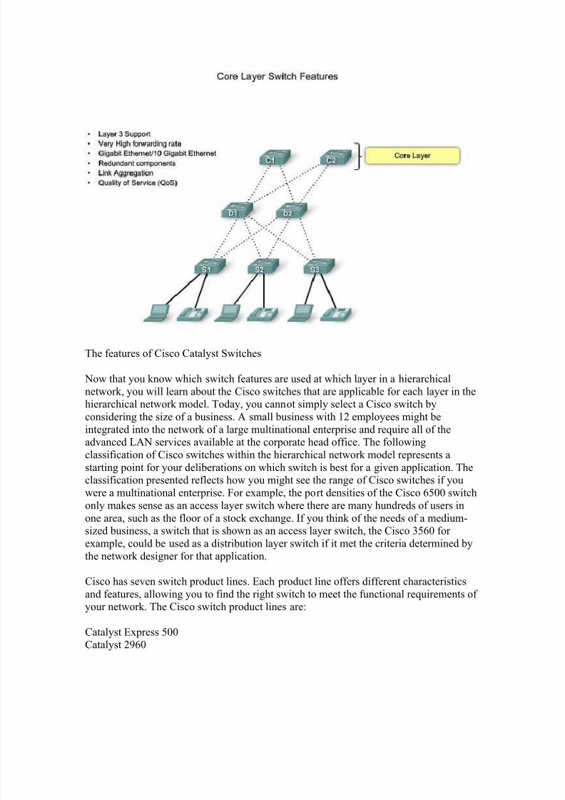
The features of Cisco Catalyst Switches
Now that you know which switch features are used at which layer in a hierarchical
network, you will learn about the Cisco switches that are applicable for each layer in thehierarchical network model. Today, you cannot simply select a Cisco switch by
considering the size of a business. A small business with 12 employees might beintegrated into the network of a large multinational enterprise and require all of theadvanced LAN services available at the corporate head office. The following
classification of Cisco switches within the hierarchical network model represents a
starting point for your deliberations on which switch is best for a given application. Theclassification presented reflects how you might see the range of Cisco switches if you
were a multinational enterprise. For example, the port densities of the Cisco 6500 switch
only makes sense as an access layer switch where there are many hundreds of users in
one area, such as the floor of a stock exchange. If you think of the needs of a medium-sized business, a switch that is shown as an access layer switch, the Cisco 3560 for
example, could be used as a distribution layer switch if it met the criteria determined by
the network designer for that application.
Cisco has seven switch product lines. Each product line offers different characteristics
and features, allowing you to find the right switch to meet the functional requirements of your network. The Cisco switch product lines are:
Catalyst Express 500Catalyst 2960

8/7/2019 cccna3 cap1
http://slidepdf.com/reader/full/cccna3-cap1 40/50
Catalyst 3560
Catalyst 3750
Catalyst 4500Catalyst 4900
Catalyst 6500
Catalyst Express 500
The Catalyst Express 500 is Cisco's entry-layer switch. It offers the following:
Forwarding rates from 8.8 Gb/s to 24 Gb/s
Layer 2 port securityWeb-based management
Converged data/IP communications support
This switch series is appropriate for access layer implementations where high port density
is not required. The Cisco Catalyst Express 500 series switches are scaled for smallbusiness environments ranging from 20 to 250 employees. The Catalyst Express 500
series switches are available in different fixed configurations:
Fast Ethernet and Gigabit Ethernet connectivityUp to 24 10/100 ports with optional PoE or 12 10/100/1000 ports
Catalyst Express 500 series switches do not allow management through the Cisco IOS
CLI. They are managed using a built-in web management interface, the Cisco Network
Assistant or the new Cisco Configuration Manager developed specifically for the CatalystExpress 500 series switches. The Catalyst Express does not support console access.
To learn more about the Cisco Express 500 series of switches, go tohttp://www.cisco.com/en/US/products/ps6545/index.html.
Catalyst 2960
The Catalyst 2960 series switches enable entry-layer enterprise, medium-sized, and
branch office networks to provide enhanced LAN services. The Catalyst 2960 series
switches are appropriate for access layer implementations where access to power andspace is limited. The CCNA Exploration 3 LAN Switching and Wireless labs are based
on the features of the Cisco 2960 switch.
The Catalyst 2960 series switches offers the following:
Forwarding rates from 16 Gb/s to 32 Gb/s
Multilayered switching

8/7/2019 cccna3 cap1
http://slidepdf.com/reader/full/cccna3-cap1 41/50
QoS features to support IP communications
Access control lists (ACLs)
Fast Ethernet and Gigabit Ethernet connectivityUp to 48 10/100 ports or 10/100/1000 ports with additional dual purpose gigabit uplinks
The Catalyst 2960 series of switches do not support PoE.
The Catalyst 2960 series supports the Cisco IOS CLI, integrated web managementinterface, and Cisco Network Assistant. This switch series supports console and auxiliary
access to the switch.
To learn more about the Catalyst 2960 series of switches, visithttp://www.cisco.com/en/US/products/ps6406/index.html.
Catalyst 3560
The Cisco Catalyst 3560 series is a line of enterprise-class switches that include support
for PoE, QoS, and advanced security features such as ACLs. These switches are idealaccess layer switches for small enterprise LAN access or branch-office converged
network environments.
The Cisco Catalyst 3560 Series supports forwarding rates of 32 Gb/s to 128 Gb/s(Catalyst 3560-E switch series).
The Catalyst 3560 series switches are available in different fixed configurations:
Fast Ethernet and Gigabit Ethernet connectivity
Up to 48 10/100/1000 ports, plus four small form-factor pluggable (SFP) portsOptional 10 Gigabit Ethernet connectivity in the Catalyst 3560-E models
Optional Integrated PoE (Cisco pre-standard and IEEE 802.3af); up to 24 ports with 15.4
watts or 48 ports with 7.3 watts
To learn more about the Catalyst 3560 series of switches, visit
http://www.cisco.com/en/US/products/hw/switches/ps5528/index.html.
Catalyst 3750
The Cisco Catalyst 3750 series of switches are ideal for access layer switches in midsize
organizations and enterprise branch offices. This series offers forwarding rates from 32
Gb/s to 128 Gb/s (Catalyst 3750-E switch series). The Catalyst 3750 series supportsCisco StackWise technology. StackWise technology allows you to interconnect up to
nine physical Catalyst 3750 switches into one logical switch using a high-performance
(32 Gb/s), redundant, backplane connection.
8/7/2019 cccna3 cap1
http://slidepdf.com/reader/full/cccna3-cap1 42/50
The Catalyst 3750 series switches are available in different stackable fixed
configurations:
Fast Ethernet and Gigabit Ethernet connectivity
Up to 48 10/100/1000 ports, plus four SFP ports
Optional 10 Gigabit Ethernet connectivity in the Catalyst 3750-E modelsOptional Integrated PoE (Cisco pre-standard and IEEE 802.3af); up to 24 ports with 15.4
watts or 48 ports with 7.3 watts
To learn more about the Catalyst 3750 series of switches, visit
http://www.cisco.com/en/US/products/hw/switches/ps5023/index.html.
Catalyst 4500
The Catalyst 4500 is the first midrange modular switching platform offering multilayer
switching for enterprises, small- to medium-sized businesses, and service providers.
With forwarding rates up to 136 Gb/s, the Catalyst 4500 series is capable of managingtraffic at the distribution layer. The modular capability of the Catalyst 4500 series allows
for very high port densities through the addition of switch port line cards to its modular
chassis. The Catalyst 4500 series offers multilayer QoS and sophisticated routing
functions.
The Catalyst 4500 series switches are available in different modular configurations:
Modular 3, 6, 7, and 10 slot chassis offering different layers of scalability
High port density: up to 384 Fast Ethernet or Gigabit Ethernet ports available in copper
or fiber with 10 Gigabit uplinksPoE (Cisco pre-standard and IEEE 802.3af)
Dual, hot-swappable internal AC or DC power supplies
Advanced hardware-assisted IP routing capabilities
To learn more about the Catalyst 4500 series of switches, visit
http://www.cisco.com/en/US/products/hw/switches/ps4324/index.html.
Catalyst 4900
The Catalyst 4900 series switches are designed and optimized for server switching by
allowing very high forwarding rates. The Cisco Catalyst 4900 is not a typical access layer
switch. It is a specialty access layer switch designed for data center deployments wheremany servers may exist in close proximity. This switch series supports dual, redundant
power supplies and fans that can be swapped out while the switch is still running. This
allows the switches to achieve higher availability, which is critical in data center
deployments.
8/7/2019 cccna3 cap1
http://slidepdf.com/reader/full/cccna3-cap1 43/50
The Catalyst 4900 series switches support advanced QoS features, making them ideal
candidates for the back-end IP telephony hardware. Catalyst 4900 series switches do notsupport the StackWise feature of the Catalyst 3750 series nor do they support PoE.
The Catalyst 4900 series switches are available in different fixed configurations:
Up to 48 10/100/1000 ports with four SFP ports or 48 10/100/1000 ports with two 10GbE
portsDual, hot-swappable internal AC or DC power supplies
Hot-swappable fan trays
To learn more about the Catalyst 4900 series of switches, visit
http://www.cisco.com/en/US/products/ps6021/index.html.
Catalyst 6500
The Catalyst 6500 series modular switch is optimized for secure, converged voice, video,and data networks. The Catalyst 6500 is capable of managing traffic at the distribution
and core layers. The Catalyst 6500 series is the highest performing Cisco switch,
supporting forwarding rates up to 720 Gb/s. The Catalyst 6500 is ideal for very large
network environments found in enterprises, medium-sized businesses, and serviceproviders.
The Catalyst 6500 series switches are available in different modular configurations:
Modular 3, 4, 6, 9, and 13 slot chassis
LAN/WAN service modulesPoE up to 420 IEEE 802.3af Class 3 (15.4W) PoE devices
Up to 1152 10/100 ports, 577 10/100/1000 ports, 410 SFP Gigabit Ethernet ports, or 64
10 Gigabit Ethernet portsDual, hot-swappable internal AC or DC power supplies
Advanced hardware-assisted IP routing capabilities
To learn more about the Catalyst 6500 series of switches, visit
http://www.cisco.com/en/US/products/hw/switches/ps708/index.html.
The following tool can help identify the correct switch for an implementation:
http://www.cisco.com/en/US/products/hw/switches/products_promotion0900aecd805036
4f.html.
The following guide provides a detailed comparison of current switch offerings from
Cisco:
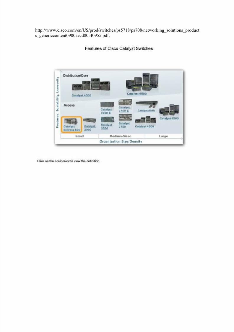
8/7/2019 cccna3 cap1
http://slidepdf.com/reader/full/cccna3-cap1 44/50
http://www.cisco.com/en/US/prod/switches/ps5718/ps708/networking_solutions_product
s_genericcontent0900aecd805f0955.pdf.
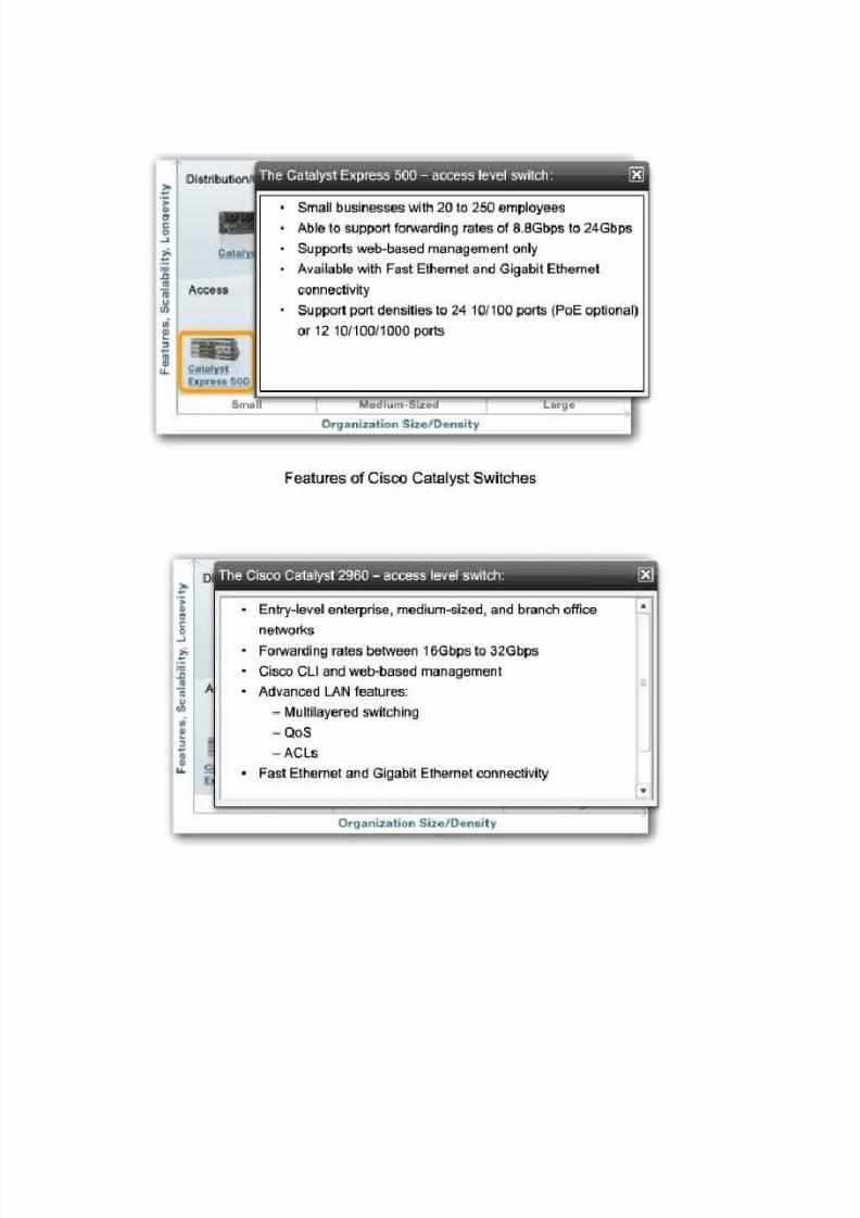
8/7/2019 cccna3 cap1
http://slidepdf.com/reader/full/cccna3-cap1 45/50

8/7/2019 cccna3 cap1
http://slidepdf.com/reader/full/cccna3-cap1 46/50
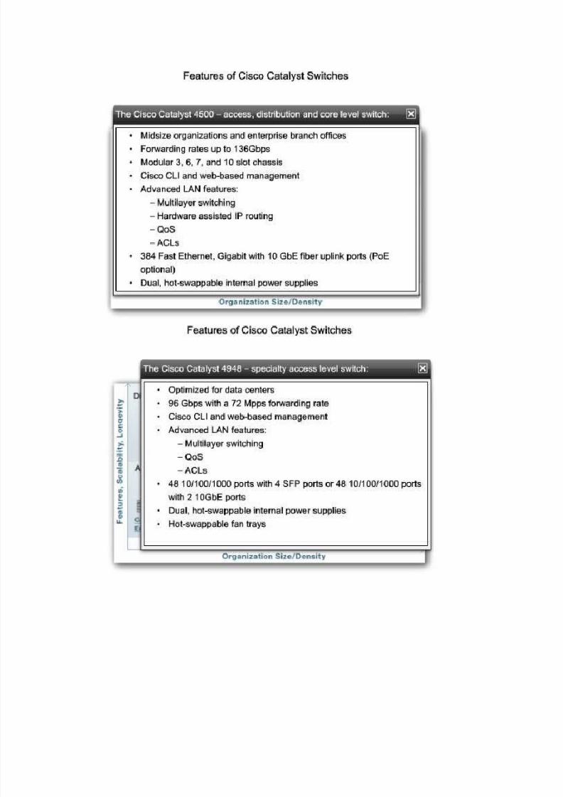
8/7/2019 cccna3 cap1
http://slidepdf.com/reader/full/cccna3-cap1 47/50
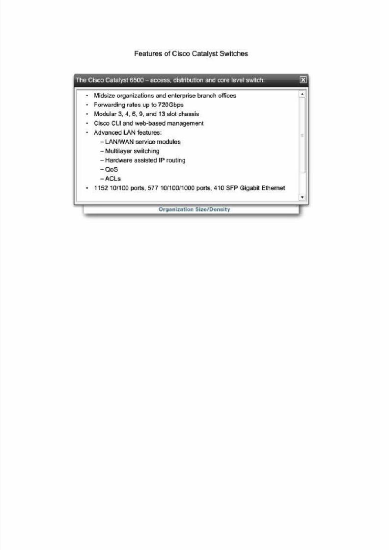
8/7/2019 cccna3 cap1
http://slidepdf.com/reader/full/cccna3-cap1 48/50
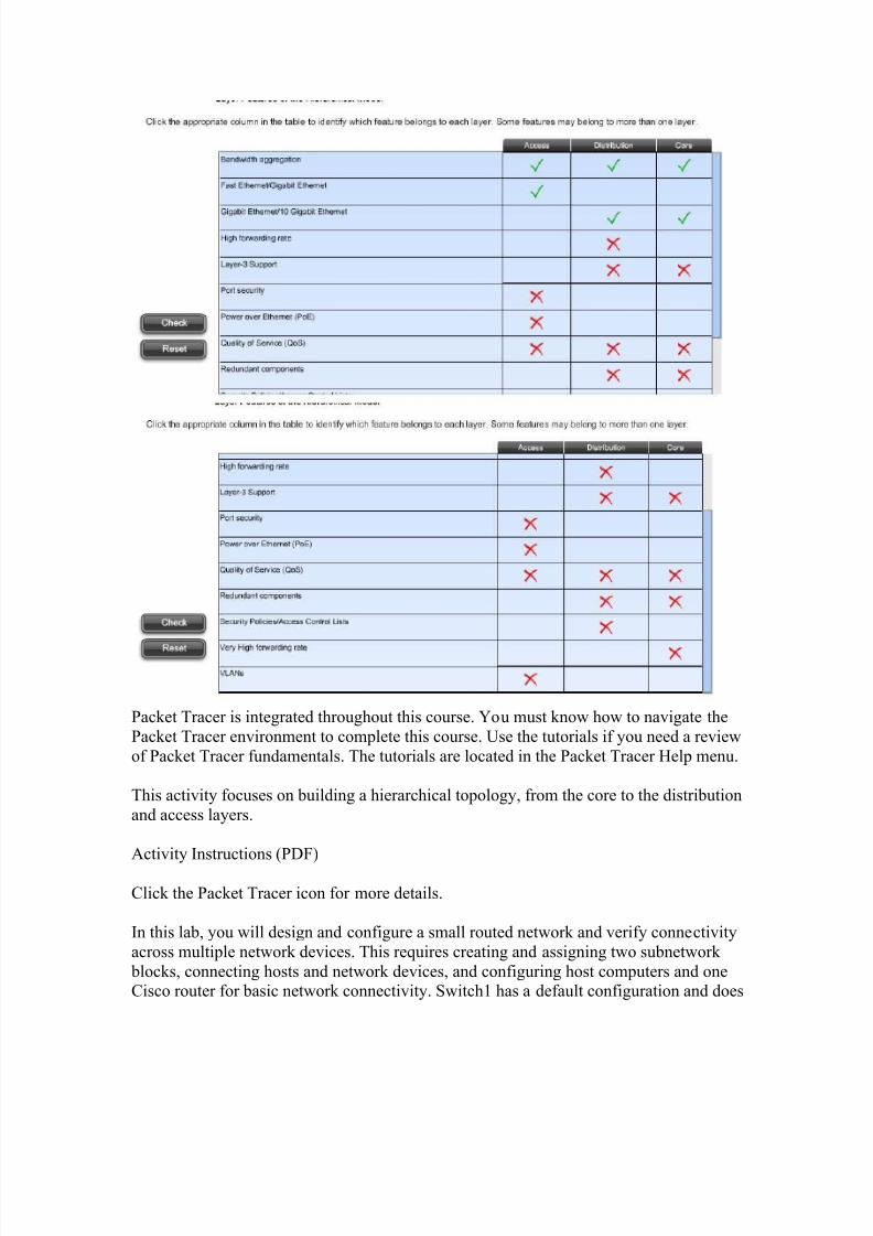
8/7/2019 cccna3 cap1
http://slidepdf.com/reader/full/cccna3-cap1 49/50
Packet Tracer is integrated throughout this course. You must know how to navigate the
Packet Tracer environment to complete this course. Use the tutorials if you need a review
of Packet Tracer fundamentals. The tutorials are located in the Packet Tracer Help menu.
This activity focuses on building a hierarchical topology, from the core to the distribution
and access layers.
Activity Instructions (PDF)
Click the Packet Tracer icon for more details.
In this lab, you will design and configure a small routed network and verify connectivity
across multiple network devices. This requires creating and assigning two subnetwork
blocks, connecting hosts and network devices, and configuring host computers and oneCisco router for basic network connectivity. Switch1 has a default configuration and does

8/7/2019 cccna3 cap1
http://slidepdf.com/reader/full/cccna3-cap1 50/50
not require additional configuration. You will use common commands to test and
document the network. The zero subnet is used.
In this chapter, we discussed the hierarchical design model. Implementing this modelimproves the performance, scalability, availability, manageability, and maintainability of
the network. Hierarchical network topologies facilitate network convergence by
enhancing the performance necessary for voice and video data to be combined onto theexisting data network.
Traffic flow, user communities, data stores and server location, and topology diagramanalysis are used to help identify network bottlenecks. The bottlenecks can then be
addressed to improve the performance of the network and accurately determine
appropriate hardware requirements to satisfy the desired performance of the network.
We surveyed the different switch features, such as form factor, performance, PoE, and
Layer 3 support and how they relate to the different layers of the hierarchical network
design. An array of Cisco Catalyst switch product lines is available to support any
application or business size.