CCARC TRI-EX MOBILE ANTENNA TOWER INSTRUCTION MANUAL Tower Instructions.pdf · 2 FOREWORD The...
37
CCARC TRI-EX MOBILE ANTENNA TOWER INSTRUCTION MANUAL 2017 EDITION
Transcript of CCARC TRI-EX MOBILE ANTENNA TOWER INSTRUCTION MANUAL Tower Instructions.pdf · 2 FOREWORD The...

CCARC TRI-EX MOBILE ANTENNA TOWER
INSTRUCTION MANUAL
2017
EDITION

1
TRI-EX TOWER INSTRUCTION MANUAL
Fourth Edition – May 2017
Prepared By G. Hutchison – W7TTY
2nd
Edition – 22 June 2014 Edited by Rik Scairpon – WX7RIK
3rd
Edition - 20 June 2015 Edited by Paula Johnson – K7PAX
4th Edition – 30 May 2017
Edited by Glen Muir WA6RQW and Paula Johnson K7PAX
COPYRIGHT © 2014 G. Hutchison
Table of Contents FOREWORD ................................................................................................................................................. 2
SETUP CREW REQUIREMENTS .................................................................................................................... 3
DEPLOYMENT CONSIDERATIONS ................................................................................................................ 4
PRECAUTIONS ............................................................................................................................................. 5
PHASE ONE: LEVELING THE TRAILER FRAME .............................................................................................. 6
PHASE TWO: DEPLOYING THE SUPPORT LEGS (OUTRIGGERS) ................................................................. 10
PHASE THREE: PREPARING THE TOWER TOP FOREWORD ....................................................................... 19
PHASE FOUR: PARTIAL TILTING OF THE TOWER ....................................................................................... 21
PHASE FIVE: FULL TILTING OF THE TOWER ............................................................................................... 25
PHASE SIX: EXTENDING THE TOWER ........................................................................................................ 28
WHILE THE TOWER IS IN USE .................................................................................................................... 31
BREAKDOWN AFTER USE .......................................................................................................................... 31
Appendix A: Motor Control Instructions .................................................................................................. 32
Appendix B: TRI-EX Tower Inspection Duty Roster ................................................................................... 33
Appendix C: NITE IZE FIGURE 9 INSTRUCTIONS ........................................................................................ 34
Appendix D: Birdseye View of Proper Support Block Placement ............................................................. 35
Appendix E: Tower Deployment Checklist ................................................................................................ 36

2
FOREWORD
The manual that accompanies the Tri-Ex Portable Antenna Tower gives a casual description of the setup procedure. The information presented in this document is intended to give a far more detailed set of sequences, with the intent being to give those persons involved a better understanding of exactly what is going on, and some consideration as to why the described method is being used.
The proper operation and maintenance of a structure such as a TRI-EX Portable Antenna Tower is a serious matter. Even a seemingly minor error or point of neglect or improper operation can result in very serious consequences up to and including severe injury or death of operators and/or nearby persons.
The total weight of the tower is close to 2500 pounds. A ten-pound side force on the top results in about 700 foot pounds torque at the base. Were the tower to be raised without the benefit of the support outriggers, it would not take too much side force at the top to topple it.
When fully set up, the tower should be considered to be a “container” of stored energy, similar to a water tower. The cables that raise the tower are storing energy. The cables, which maintain the position of the outriggers, are storing energy. The jacks, pads, and the blocks, which support them, are also storing energy. The guys affixed to the top of the tower store energy as they absorb side forces caused by wind.
What is the source of the energy? GRAVITY!!! Respect the forces stored and managed by the tower and its design, as to not do so could result in untoward consequences.
Note the two terms that are used to describe the two major operations to get the tower from portable as a trailer to the in-service condition:
Tilting the tower: Elevating the collapsed tower from the horizontal trailer position to vertical upright position.
Extending the tower: Extending the sections to the fully extended operating position.
3
SETUP CREW REQUIREMENTS It is highly recommended that the tower deployment crew be appointed to consist of the following members:
Tower Master / Team Leader – This would be a qualified individual who would supervise the entire operation.
Assistants – These would be a team of individuals who collectively can function so as to assure safe and proper set-up, operation and care of the structure. Recommendation would be two people, as if there are too many people involved, the process enters the realm of “too many cooks.”
Checklist Coordinator – the person who reads and calls out the steps from the checklist (found in Appendix E) and checks off each step as it is performed.
Safety Officer – to observe and monitor the safety of the deployment crew only, and not participate in the actual work of deploying the tower.
The qualifications of the selected staff should include a background in such areas as good mechanical knowledge, and some experience in construction or a similar discipline wherein awareness of good personnel safety practices is a way of life. The ability to observe directly or “out of the corner of an eye” minute points which could end up becoming major problems and which can be addressed or corrected quickly is a considerable asset.
Once a person or persons have agreed to assume the responsibility for the tower’s maintenance and operation, support them well.
A good assortment of hand tools and maintenance supplies is essential to a successful, incident-free effort. It is recommended that those persons involved rely on their own resources as opposed to imposing on your association’s financial resources to supply same. Tools not owned by a specific person tend to disappear over time, and those who own tools will keep much closer track of them, their use, and care.
Materials used should be of the highest quality. There is no benefit when thrift is substituted for doing things correctly. In short, being cheap can quickly become a gateway to disaster.

4
DEPLOYMENT CONSIDERATIONS
The following is presented as a means of determining just where and how the trailer is to be placed before the real work begins. It is pretty much common sense, but is intended to stimulate some thought.
The first consideration is the nature of the terrain upon which it is to be set up.
Ideally it should be perfectly level. It should be a hard, packed surface. It should be a nice, warm, breeze-free day. But typically these conditions will seldom be ideal, so we must begin to consider the actual set up environment, and how to deal with the conditions at hand.
Look for power lines, and stay well away.
Trees specific distances and directions away from the location make ideal wire antenna supports. Placing the tower so as to take advantage of these additional antenna supports adds additional resources to the radio operation.
Muddy, water-soaked ground is not acceptable. The support blocks would tend to sink into the soil. Desert sand would most likely permit some degradation of support, and be unacceptable for grounds and anchors unless driven quite deep.
Packed, crushed rock would give good support, but driving ground rods and anchor stakes might be a problem.
Locations such as are encountered in city parks, fairgrounds, and open meadows are essentially ideal. The soil is usually grass-covered, firm, and fairly close to level. Ground rods and anchor stakes can be driven in with moderate effort.
Wind is another consideration.
The tower is best situated so that the tongue of the trailer points downwind from the prevailing winds.
Under these conditions guys affixed to anchors driven the prescribed distance away from and in the direction of each of the support legs give the best support and stability to the top of the tower under windy conditions.
The procedure will be presented step-by-step, and when appropriate, each phase of the procedure will be accompanied with an explanation as to why it is done and pitfalls to be aware of.

5
PRECAUTIONS
Stake out a safety area of approximately 100’ x 100’ using steel fence stakes and “CAUTION” tape, with the trailer/tower centered within this area. Flag the stakes with fluorescent surveyor’s tape.
ALL PERSONNEL participating in the tower work should be equipped with Hard Hats, Safety Glasses, Good Quality Work Gloves, and Heavy, preferably Steel-Toed, Footwear. Entry into the work area should be restricted to those so equipped.
A Well-provisioned FIRST AID KIT should be readily accessible in the event of any injuries.
A minimum of THREE FIRE EXTINGUISHERS should be prominently displayed and accessible. Gasoline-powered generators present a fire hazard. Deploy fire extinguishers as follows:
One by Antenna Tower One by each generator One by the Fuel Depot (50 feet from any ignition source) One in each Radio Tent
Those working on ladders when assembling the tower top should be equipped with suitable safety harnesses. If using freestanding a-frame ladders, the use of safety harnesses with these might actually be a hazard.
Pockets of working personnel should be empty. An inadvertent poke by an item in one’s pocket can be a serious distraction or hazard.
No eating or beverages in the work area.
Keep all trash picked up. Tools should be kept off the ground. Loose wires, ropes, and cables can be tripping hazards.
ALL WORK should be accomplished during daylight hours.
Working in INCLEMENT WEATHER adds additional hazards.
The appointed safety officer should be present to observe all evolutions of the tower deployment process.
The winch motor draws a substantial amount of current. The power source and the cords leading to it should be capable of handling the starting surge current which is upward of twenty to thirty amperes, and sustaining the running current without dropping the line voltage to where the motor will switch into the start mode, causing it to overheat and possibly fail completely.

6
PHASE ONE: LEVELING THE TRAILER FRAME
Let us now begin set up of the tower.
1-1. The trailer shall have been situated in a location and positioned in accordance with the positioning considerations previously discussed.
1-2. Remove the three jack support blocks from the accessories platform, and position each block such that the feet on the two support jacks at the rear of the trailer and the hitch jack on the tongue of the trailer are centered beneath the foot of each jack. Place the square plywood jack block toppers on top of the jack support blocks. The top surface of each block should be as close to level as possible.
Figure 1 - Jack Support Blocks on Trailer

7
Figure 2 - Jack Support Block under Tongue Jack
Figure 3 - Jack Support Blocks under Rear Jacks
8
1-3. Place a carpenter’s level on the frame of the trailer inside the triangular cage formed by the tower’s vertical support arrangement such that the level will indicate the side to side plumb of the trailer. Location for the level is labeled LP-1 (Leveling Point 1)
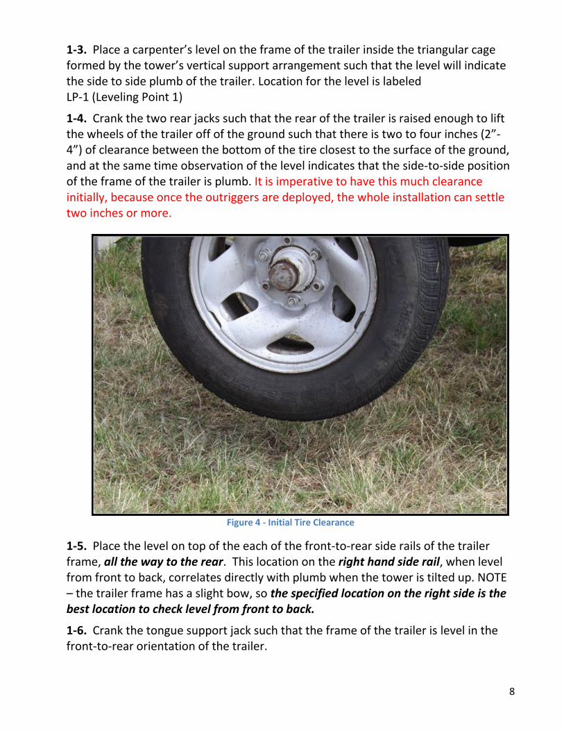
1-4. Crank the two rear jacks such that the rear of the trailer is raised enough to lift the wheels of the trailer off of the ground such that there is two to four inches (2”- 4”) of clearance between the bottom of the tire closest to the surface of the ground, and at the same time observation of the level indicates that the side-to-side position of the frame of the trailer is plumb. It is imperative to have this much clearance initially, because once the outriggers are deployed, the whole installation can settle two inches or more.
Figure 4 - Initial Tire Clearance
1-5. Place the level on top of the each of the front-to-rear side rails of the trailer frame, all the way to the rear. This location on the right hand side rail, when level from front to back, correlates directly with plumb when the tower is tilted up. NOTE – the trailer frame has a slight bow, so the specified location on the right side is the best location to check level from front to back.
1-6. Crank the tongue support jack such that the frame of the trailer is level in the front-to-rear orientation of the trailer.

9
1-7. Re-check the side-to-side alignment of the frame as accomplished in step four of this procedure. Make minor corrections of any side-to-side misalignment by adjusting the jack on the side of the trailer that has the MOST clearance between the bottom of its respective tire and the ground.
1-8. Recheck front-to-rear plumb using the level. Correct misalignment by adjusting the tongue jack.
1-9. Check and recheck as necessary to assure that the frame of the trailer is plumb side- to-side and front to rear, and that the wheels of the trailer ARE NOT touching the ground.
WHAT YOU HAVE ACCOMPLISHED THUS FAR: You have adjusted the positioning of the trailer frame such that it is true and level in all directions and that no support of the trailer structure is borne by the wheels and axle.
The tires should be off the ground completely as the cushioning effect of the axle springs and tires would render significant instability when the tower is fully erect.
The large size of the wooden jack blocks assures that the weight of the tower system is distributed over a larger surface area than would be afforded by the pads of the jacks themselves. It is therefore more stable, and misalignment of the plumb is less likely to occur.
Phase One of the tower set-up is now complete.
10
PHASE TWO: DEPLOYING THE SUPPORT LEGS (OUTRIGGERS)
The tower is engineered so that the maximum un-guyed vertical stability is afforded when the two rear outrigger supports have been properly extended and firmly emplaced.
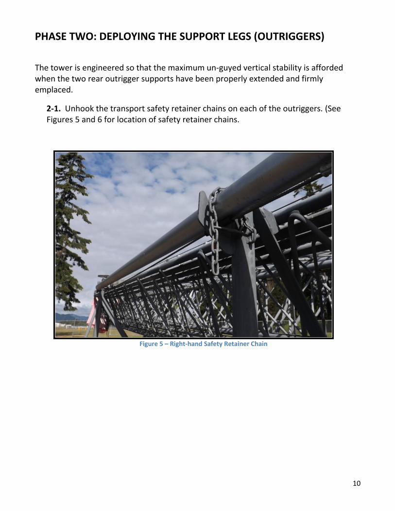
2-1. Unhook the transport safety retainer chains on each of the outriggers. (See Figures 5 and 6 for location of safety retainer chains.
Figure 5 – Right-hand Safety Retainer Chain
11
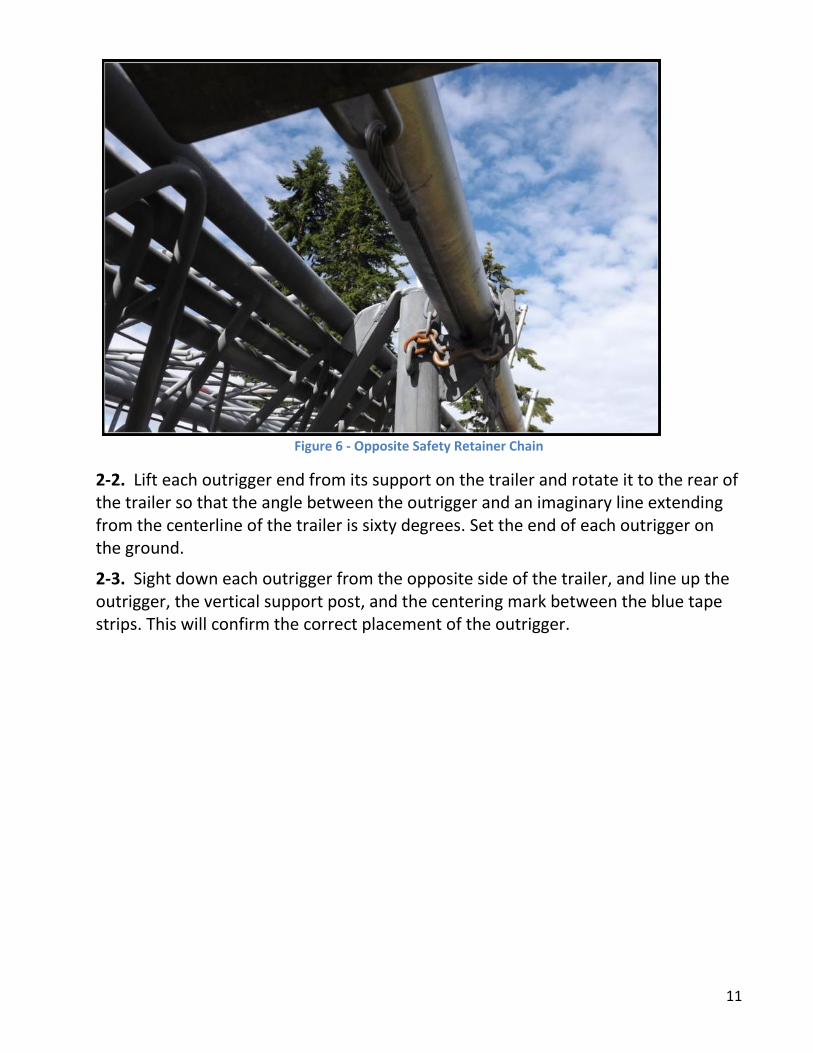
Figure 6 - Opposite Safety Retainer Chain
2-2. Lift each outrigger end from its support on the trailer and rotate it to the rear of the trailer so that the angle between the outrigger and an imaginary line extending from the centerline of the trailer is sixty degrees. Set the end of each outrigger on the ground.
2-3. Sight down each outrigger from the opposite side of the trailer, and line up the outrigger, the vertical support post, and the centering mark between the blue tape strips. This will confirm the correct placement of the outrigger.
12
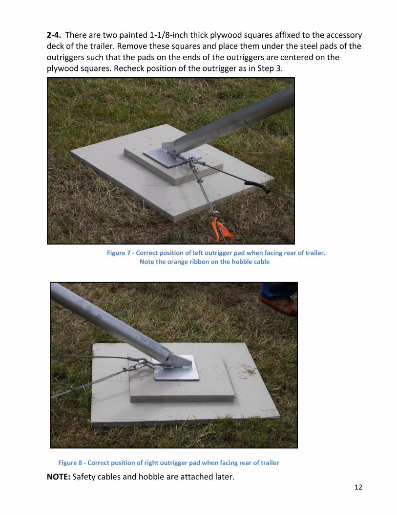
2-4. There are two painted 1-1/8-inch thick plywood squares affixed to the accessory deck of the trailer. Remove these squares and place them under the steel pads of the outriggers such that the pads on the ends of the outriggers are centered on the plywood squares. Recheck position of the outrigger as in Step 3.
Figure 7 - Correct position of left outrigger pad when facing rear of trailer. Note the orange ribbon on the hobble cable
Figure 8 - Correct position of right outrigger pad when facing rear of trailer
NOTE: Safety cables and hobble are attached later.
13
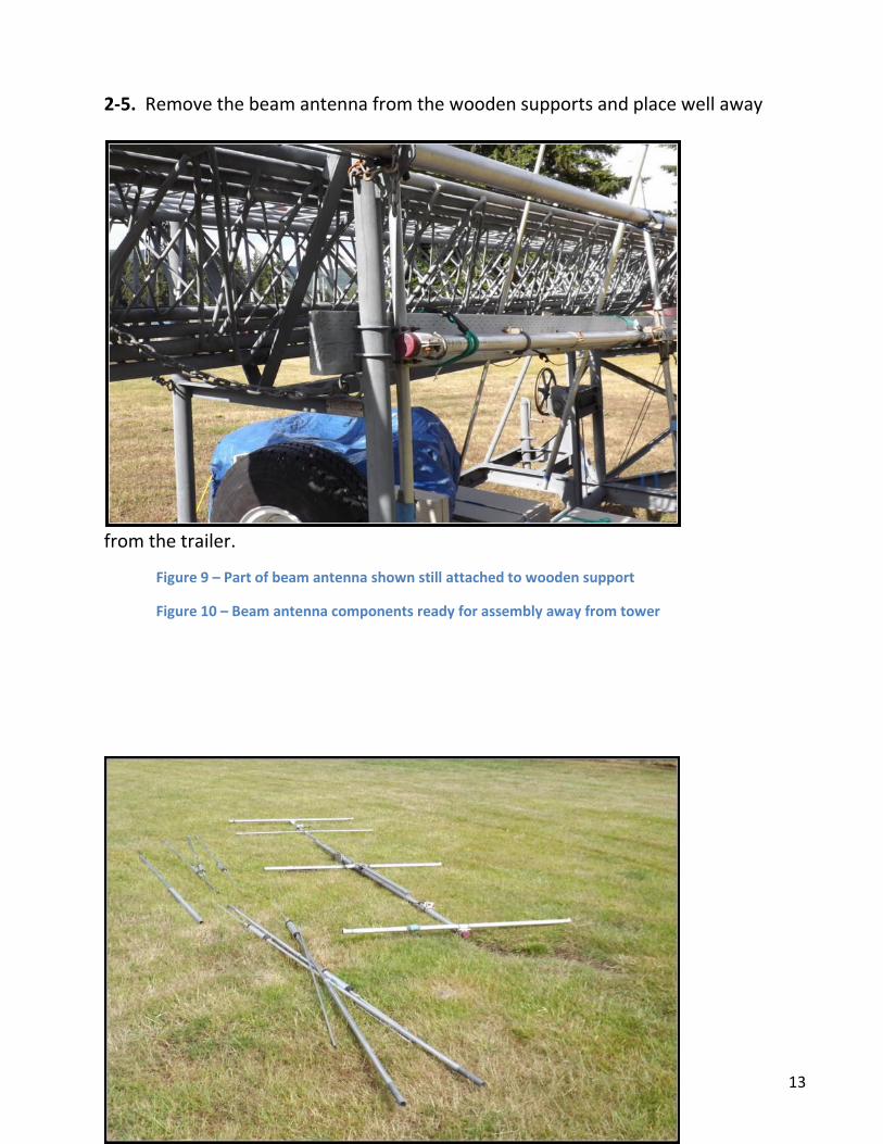
2-5. Remove the beam antenna from the wooden supports and place well away
from the trailer.
Figure 9 – Part of beam antenna shown still attached to wooden support
Figure 10 – Beam antenna components ready for assembly away from tower
14
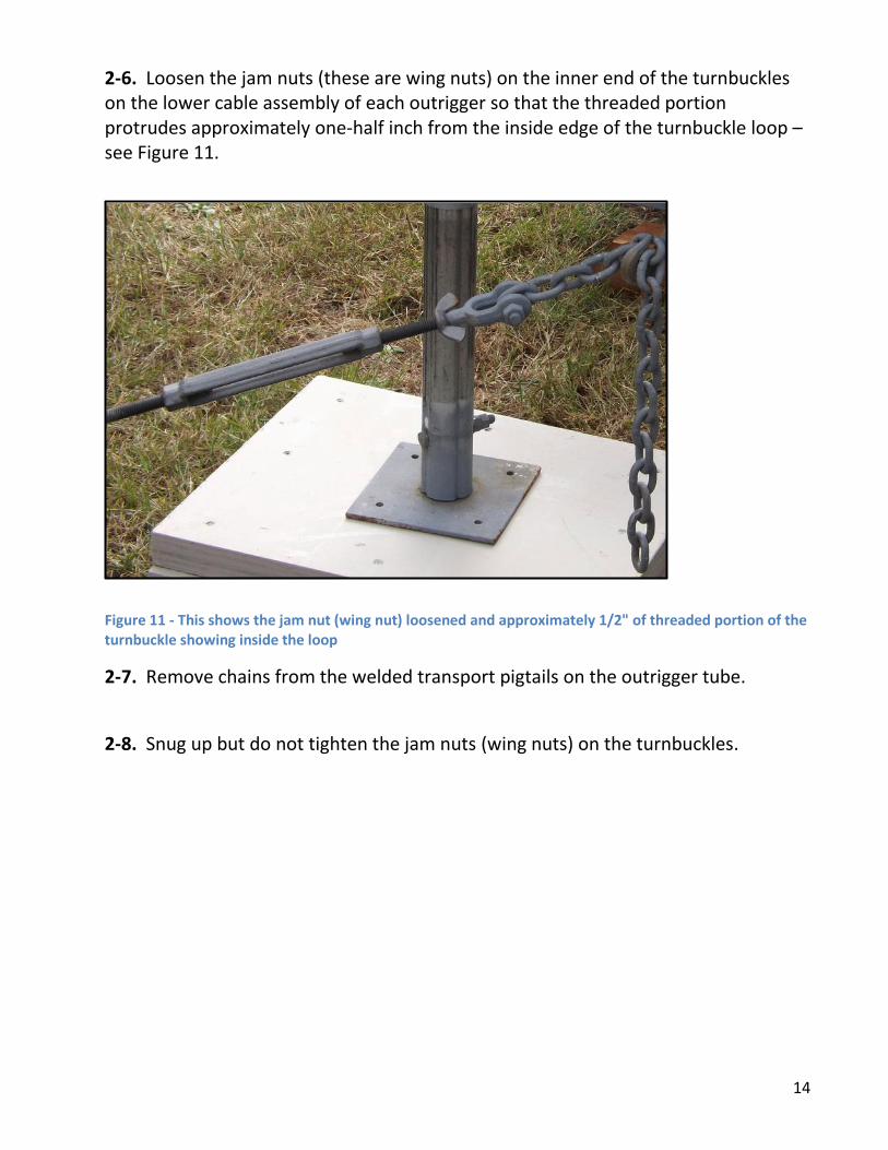
2-6. Loosen the jam nuts (these are wing nuts) on the inner end of the turnbuckles on the lower cable assembly of each outrigger so that the threaded portion protrudes approximately one-half inch from the inside edge of the turnbuckle loop – see Figure 11.
Figure 11 - This shows the jam nut (wing nut) loosened and approximately 1/2" of threaded portion of the turnbuckle showing inside the loop
2-7. Remove chains from the welded transport pigtails on the outrigger tube.
2-8. Snug up but do not tighten the jam nuts (wing nuts) on the turnbuckles.

15
2-9. Affix the chain at the end of cable assembly to its corresponding attachment point, which is a pelican hook on the rear of the trailer frame. Remove slack by rotating the turnbuckle.
Figure 12 – chain affixed to pelican hook at rear of trailer frame – it will probably be fastened by a link close to the middle of the chain
2-10. The next procedure involves affixing a safety cable or “hobble” between the feet of each outrigger. This safety cable is not a part of the procedures in the trailer manufacturer’s manual. It has been added since it addresses a potential condition wherein the outriggers might migrate or slip apart and would not properly support the tower. The safety cable prevents such slippage and therefore serves to enhance the stability (and safety) of the tower. See Figures 13 and 14.
Figure 13 - Left Outrigger Figure 14 - Right Outrigger

16
a. Attach each end of the safety cable to the loops at the ends of the outriggers that are resting on the pads. Hand tighten the hobble links.
b. Remove the slack until hobble is snug by repositioning the end of each outrigger, assuring that the angle between the outriggers is equal with respect to the centerline of the trailer. There is a red center marker on the hobble cable. Ensure that it lines up with the center of the trailer.
2-11. Using the jacks on the rear of the trailer, raise the rear of the trailer frame on either side one-half inch higher off of the support block than established in Phase 1 of this procedure. Use a tape measure to measure the distance.
2-12. Adjust the ends of the lower outrigger support cables by pulling the cable as taut as possible and affixing the appropriate link of each support cable chain to the pelican hook welded to the trailer frame just below the tower (RED) safety locks. Observe that there will still be some slack in the cables, and the square pads on the outriggers must be centered on the plywood squares. Refer to picture in Figure 12.
2-13. Loosen the jam nuts on the turnbuckles, and using a wrench and short pry bar, adjust the turnbuckles so that the slack in the cables is taken up, and that substantial tension is imparted to each cable.
2-14. Inasmuch as a tensiometer is an expensive device and is therefore not provided, appoint a mechanically knowledgeable individual to check the tension on each cable such that when a side force is applied to the center of each cable span, the tension is firm enough so that with said force applied, the deflection of the cable is no more than perhaps one-half inch in each cable.
2-15. Snug up the jam nuts on each turnbuckle.
NOTE: ONE PERSON should check the tension in both cables. A SECOND PERSON should then check the tension in an identical manner. BOTH persons should be in agreement that the tension on each cable is substantial and that the cable deflection with the applied force is uniform on both outriggers. Only proceed to the next step when agreement is reached.
2-16. Using the right and left rear jacks, lower the rear end of the trailer until the entire weight of the trailer rests on the outriggers, and that there is approximately ¼-inch clearance between the bottoms of the jack feet and the tops of the support blocks.

17
2-17. Observe a carpenter’s level placed across the v-frame of the trailer at the rear of the tower notch to check the side-to-side plumb of the frame.
Figure 15 - checking for level from side to side
18
2-18. If the bubble of the level indicates that one side is high, loosen the jam nuts and using the pry bar, adjust the turnbuckle on the opposite outrigger so as to increase the tension on the right hand cable thus raising the that side until the frame is plumb. It may be necessary to raise the jack on the low side of the frame so as reduce the tension on the cable allowing easier adjustment of the turnbuckle. Following the adjustment, snug up the jam nuts and back off on the low side jack thus lowering the frame until there is some space between the jack pad and the jack support block. Recheck the level, and if necessary repeat the adjustment process until the level indicates that the frame is plumb, and all support of the rear of the trailer is borne by the outriggers.
2-19. When the side-to-side leveling procedure is completed, tighten the jam nuts sufficient to prevent inadvertent loosening.
2-20. Crank the two rear jacks such that the gaps between the feet of the jacks and the tops of the support jack blocks are closed, and a small amount of force is exerted on the jack support block. Suggested amount is about 1/3 to 1/2 turn of each crank after resistance is felt when closing the gap. This is simply taking up the slack, and adds additional support and stability.
2-21. Place the level on the front-to-rear right-side frame rail at the rear of the frame and correct the front-to-rear level using the tongue jack. (Don’t use the left-side frame rail - it is not as accurate a measure.)
2-22. Locate the 3 anchor posts, which are the four-foot lengths of ¾-inch form stakes with a welded washer in one end, which are stored in the tube behind the cargo box on the trailer. Drive each one fifty feet from the center of the base of the tower and in line with the two outriggers and the tongue of the trailer. The top of each anchor should extend at least six-inches above the ground. Until the top guys are affixed below the washers in the anchor posts, place a road cone over each anchor so as to avoid personnel tripping over them.

19
PHASE THREE: PREPARING THE TOWER TOP
You are now ready to prepare the top of the tower.
NOTE: It is cautioned that falling or dropped objects can cause injuries and/or flaring tempers. Each person working in an elevated location such as the top of a ladder should have a ground man whose sole job is to maintain focus on the person on the ladder, and to assist the “high” man wherever possible.
Sufficient hardware has been supplied to allow installation of a crosspiece at the top of the tower suitable for support of antennas strung between the tower and nearby trees, as well as the capability of attaching messenger lines for support of the cabling associated with whatever antenna arrangement has been planned for the top of the tower. See figure 16 for view of finished installation. Details follow.
Figure 16 - Cross Piece Attachment Orientation
The weight loading rating of the top of the tower per the manufacturer’s manual is 250 pounds. This should be more than sufficient to support any reasonable antenna and hardware arrangement. The messenger line(s) should be long enough to touch the ground when the tower is at full height, and of sufficient strength to readily support the weight of the cabling. Be sure to secure the cabling to the messenger line with Cable ties every six feet or so.

20
The booms of beam antenna assemblies will most likely be of sufficient length to require partial erection of the tower for proper assembly.
The erecting cable of the tower is strong enough to allow sustained partial erection of the tower with no adverse effects. It is recommended that while the tower is partially erected for the assembly work, a wooden safety support be used to partially support the upper end of the tower and to give lateral stability while personnel are assembling the top. See Figure 15 in Phase 4.
Layout and organize the components and hardware prior to beginning work so as to minimize work time and assure proper assembly.
3-1. Locate the crossbar – see Figure 17 for view of crossbar assembly as stowed.
Figure 17 - Crossbar Assembly as Stowed
21
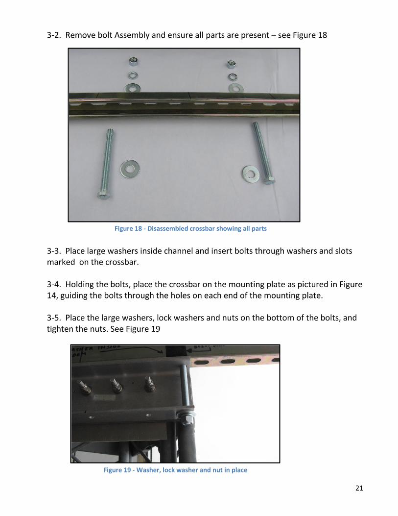
3-2. Remove bolt Assembly and ensure all parts are present – see Figure 18
3-3. Place large washers inside channel and insert bolts through washers and slots marked on the crossbar. 3-4. Holding the bolts, place the crossbar on the mounting plate as pictured in Figure 14, guiding the bolts through the holes on each end of the mounting plate. 3-5. Place the large washers, lock washers and nuts on the bottom of the bolts, and tighten the nuts. See Figure 19
Figure 18 - Disassembled crossbar showing all parts
Figure 19 - Washer, lock washer and nut in place

22
PHASE FOUR: PARTIAL TILTING OF THE TOWER
4-1. Affix the electric driving motor to the trailer frame adjacent to the tower tilting winch. This is a hinge-type of arrangement designed to allow the tension on the drive belt to be a function of the weight of the motor. The motor is held on the trailer frame with a locking lynchpin.
4-2. Install the drive belt on the pulleys.
4-3. Note that the motor turns in opposite directions when erecting and lowering the tower, as compared to when the tower is being raised or lowered. The center-off switch for the motor has been marked accordingly. The switch is sensitive, so practice a little before you plug in the motor.
4-4. Remove the transport safety chain from the top end of the tower. Properly used, the chain loops through all sections of the tower to prevent forward slippage of the tower due to vehicle braking while it is being transported.
4-5. Ensure that the winch motor control switch is in the OFF (center) position.
4-6. Ensure that the tower vertical safety stops (RED) are in the open – outermost position.
4-7. Connect the motor to a 110V AC electrical source sufficient to allow the motor to run properly. A power source of insufficient capacity will cause the motor to overheat or fail.
4-8. Tattletales should be affixed to the chain loops attached just below the top platform of the tower.
4-9. The temporary mechanical arrangement of this system is hazardous in that the belt/pulley arrangement is not enclosed. BE CAREFUL!!!
4-10. Clear all unnecessary personnel from the vicinity of the tower
4-11. When ready, announce in a loud voice “TILTING TOWER”.
4-12. Actuate the switch to tilt the tower partway up– see Attachment A.
4-13. When the top of the tower is sufficiently elevated so as to allow installation of the antenna booms, stop the motor, and disconnect the power source.

23
4-14. Place the prepared wooden 2x4 safety support on the v-frame of the trailer at the point where the front of the tower rests during transport. See Figure 20. The upper notch of the wooden support should be engaged with the tower and the tower MANUALLY lowered until the tower is in a stable position, supported from underneath by the wooden support and some tension on the tower erecting cable. Manual operation allows better control of the winching process.
Figure 20 - 2x4 Safety Support
4-15. It may be necessary to extend the tower from the fully nested position to facilitate the top assembly work. Perform this step by MANUALLY operating the tower extension winch pulley located adjacent to the winch drum at the bottom of the tower. Manual performance of this step is mandatory due to the need for precise control of the winching process.
4-16. Proceed with the top assembly work until ready to fully erect the tower. Figure 21 shows the detail of the top of the tower once the antenna mast has been inserted. Note the square wood “bearing” that allows the antenna to be turned.

24
Figure 21 - Detail of Mast Mount – NOTE - this is the old crossbar installation. See Phase 3 for new crossbar mount.
4-17. Prior to fully erecting the tower, be certain that all cabling, tattletale lines, and auxiliary antenna support lines are of lengths sufficient to allow raising the tower to its full height and be able to reach the intended anchor or operating point(s).

25
PHASE FIVE: FULL TILTING OF THE TOWER Once all hardware and assemblies have been readied, it is time to TILT the tower to its full vertical position.
Check all cabling, messengers, auxiliary antenna support cables, and guy assemblies to assure that no fouling, twists, or catches will take place as the tower is brought to the fully vertical position. All electrically actuated devices should have been checked for proper operation prior to completion of the top assembly process.
5-1. Place the tower vertical safety stops (RED) at the rear of the trailer frame in the retracted position.
5-2. MANUALLY actuate the tilting winch by turning the large pulley, sufficient to raise the tower off of the temporary wooden support and remove it from the frame. Stow it under the trailer frame. It will be needed when the tower system use has been completed and the system is being broken down.
5-3. Check the winch motor switch so as to assure that it is in the OFF (center) position.
5-4. Connect the motor to a 110V AC electrical source sufficient to allow the motor to run properly. A power source of insufficient capacity will cause the motor to overheat or fail.
5-5. The temporary mechanical arrangement of this system is hazardous in that the belt/pulley arrangement is not enclosed. BE CAREFUL!!!
5-6. Clear all unnecessary personnel from the vicinity of the tower.
5-7. ALL TOWER CREWPERSONS MUST BE PRESENT AS OBSERVERS! During the erecting process, observers noting any irregularity or potential problem shall immediately halt the process by shouting STOP!!!
5-8. When ready, the winch operator will announce in a loud voice: “TILTING TOWER”.
5-9. Actuate the winch switch to tilt the tower to full vertical– see Attachment A.
5-10. The winch operator should mind the winch arrangement remaining alert to respond to any “STOP!!!” commands from the observers.
5-11. When the butt of the tower is within three inches (3”) of the notch at the rear of the trailer frame, the winch operator shall stop the winch.
5-12. The power source should now be disconnected, and the large winch pulley MANUALLY actuated so as to completely draw the butt of the tower securely into the notch.

26
5-13. Lock the tower by positioning the safety stops in the lock position, and secure them in position with a bungee cord hooked between the bolts, which protrude from each stop.
NOTE: When initially leveled, the center of gravity of the system was on the centerline of the trailer approximately midway between the center of the front hitch and the centerline of the tower hinge pivots.
Erecting the tower to full vertical shifts the center of gravity of the system to the center of the tower. It is therefore necessary to re-check the plumb of the system to assure that the support of the tower is accurately aligned such that the center of gravity is at the apex of the two outriggers and the centerline of the hitch jack, and that the downward forces on each of the outriggers and the hitch jack are equal.
5-14. Using the carpenter’s level check the side-to-side and front-to-rear plumb of the frame. You will have to raise the tower manually to place the level underneath to check side-to-side. When checking front-to-back, it is likely the level will show that the hitch is a bit higher because there is less weight on it. Adjust the hitch jack accordingly, and the system should be plumb. Be sure to secure the jack handle so it is not accidentally turned.
5-15. Place the carpenter’s level on each of the vertical legs of the tower and verify that the tower is indeed vertical, and adjust if necessary. Be sure that the slight amount of lift to the rear jacks is removed, then when assured that the assembly is plumb, restore the slight pressure on the rear jacks to restore the additional safety this step affords.
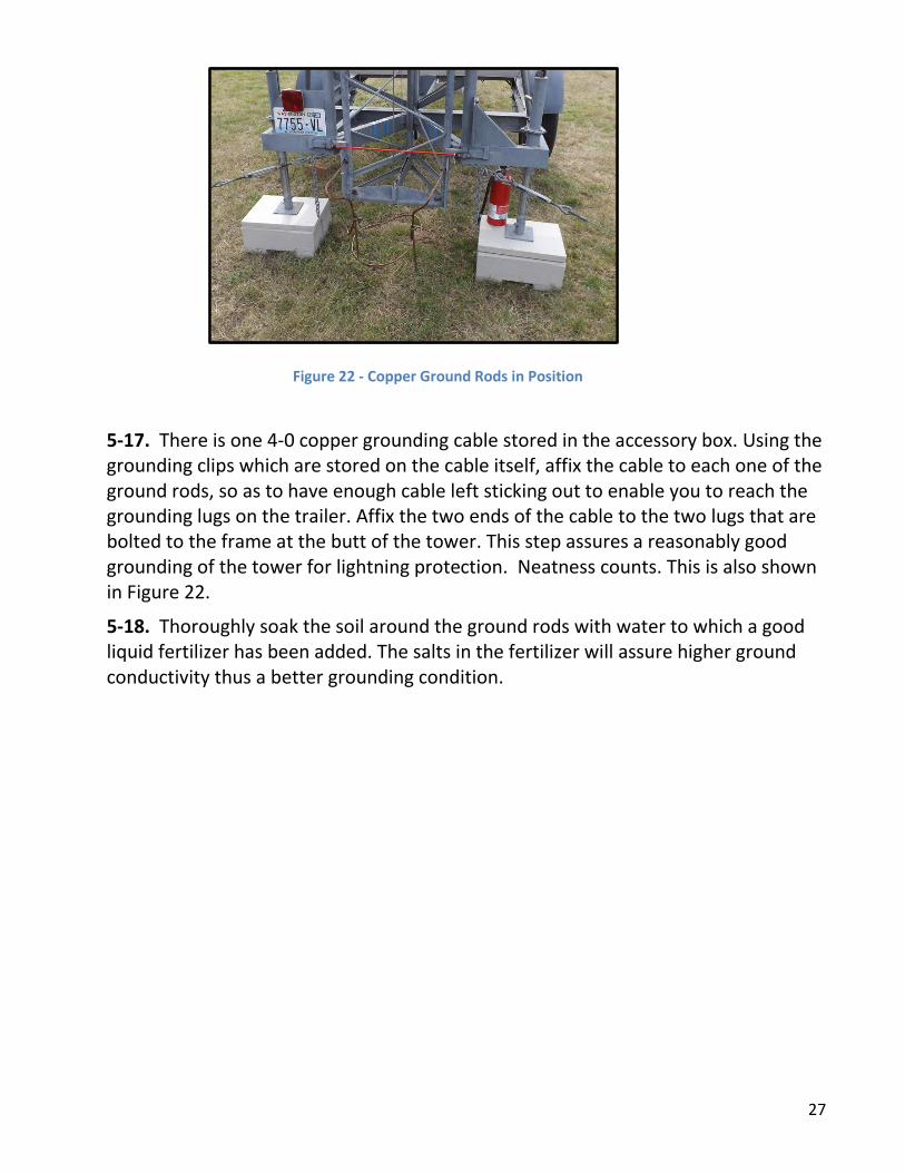
5-16. Drive the two copper ground rods which are stored in the accessory box into the ground at points which are approximately six-inches towards the outside of each of the rear jacks of the tower and approximately six inches to the rear of the rear frame of the trailer. The rods should protrude approximately four inches from the ground as show in Figure 22 below.
27
5-17. There is one 4-0 copper grounding cable stored in the accessory box. Using the grounding clips which are stored on the cable itself, affix the cable to each one of the ground rods, so as to have enough cable left sticking out to enable you to reach the grounding lugs on the trailer. Affix the two ends of the cable to the two lugs that are bolted to the frame at the butt of the tower. This step assures a reasonably good grounding of the tower for lightning protection. Neatness counts. This is also shown in Figure 22.
5-18. Thoroughly soak the soil around the ground rods with water to which a good liquid fertilizer has been added. The salts in the fertilizer will assure higher ground conductivity thus a better grounding condition.
Figure 22 - Copper Ground Rods in Position

28
PHASE SIX: EXTENDING THE TOWER When everything checks out satisfactorily, the final phase is to extend the tower.
6-1. Police the interior of the fenced working area so that there is no trash or debris which could cause a tripping hazard.
6-2. All tools should be accounted for and stored in their boxes or pouches and placed on the accessory platform of the trailer.
6-3. Loose/unused lines and cables should be coiled.
6-4. Make sure the power is disconnected from the motor assembly.
6-5. Remove the drive belt from the two pulleys.
6-6. Depress the lock on the head of the pivot pin and remove it from the erecting motor pivot while having an assistant hold the motor. (It can be awkward due to the weight)
6-7. Mount the motor adjacent to the extending winch, locking the motor in place with the pivot pin.
6-8. Mount the drive belt between the winch pulley and the motor pulley.
6-9. Assign a line handler to each of the tattletales, and also as needed to the assorted ropes and cables from the support piece mounted at the top of the tower.
NOTE ABOUT THE “TATTLETALES.” The rope/line used for the “tattletales” is in actuality a military-grade twisted polyester line developed for small military field antenna set-ups. Under extreme conditions it WILL NOT support the stresses the tower is capable of exerting in substantial weather conditions. We use the “tattletales” as sensors to determine changing conditions which could be adverse. This is WHY we maintain a regular periodic check on their tension, so as to ascertain any change which would mandate immediate investigation and appropriate corrective action.
6-10. Prior to raising the tower the line handlers shall trail their respective lines out towards and beyond the anchor posts so there will be minimal chance of knots and loops forming in the tattletales.
6-11. After trailing out the tattletales, line handlers shall slip a 12-inch piece of 1/2 –inch dia. vinyl tubing over the tattletales to act as chafing guards when the lines are secured after the tower is at full height. Rebar is rough and will damage and thus weaken unprotected lines.
NOTE: There are no electrical interlocks in the tower extension system. BE CAREFUL!!!

29
A critical point of observation is the RED up stop on the inside of the forward outside leg (bottom section) of the tower, approximately 54 inches below the top.
The very bottom of the leg of the second section of the tower has a guide forged into it that rides on the inside of the first tower section.
When the tower is at maximum height the guide on the second section runs into the up stop on the inside of the first section, preventing further extension of the tower.
When extending the tower it is imperative to monitor the proximity of the guide to the up stop, so as to prevent damage or jamming of the structure.
Problems can be avoided by stopping the extension of the tower just before the guide and the up stop engage. Completion of the extension process must then be done MANUALLY, thus avoiding any problems.
In addition to the RED up stop, pieces of RED tape have been placed on the tower tubes to aid in the determination of when the tower is fully extended.
6-12. Assign a tower crewmember to observe the RED up stop engagement between the first and second tower sections. Binoculars are recommended for this step.
6-13. Clear the safety area of extraneous personnel, visitors, etc.
6-14. All line handlers shall watch the extension process
6-15. During the extending process, any observer noting any irregularity or potential problem shall immediately halt the raising process by shouting STOP!!!
6-16. The winch motor operator shall make a final check to see that the safety area is ready.
6-17. Assure that the winch motor switch is in the OFF (center) position
6-18. Connect a suitable 110V AC power source to the winch motor assembly.
6-19. When ready, the winch operator will announce in a loud voice: “EXTENDING TOWER!!!” and then actuate the switch, starting the lift – see Attachment A.
6-20. The winch operator should mind the winch arrangement remaining alert to any “STOP!!!” commands from the observers.
6-21. When the guide on the second section of the tower is within a few inches of engaging with the up stop at the top of the outer section the up stop observer shall shout STOP!!!
6-22. The winch operator shall stop the winch, and disconnect the AC power.
30
6-23. The winch operator must then MANUALLY operate the winch pulley and continue extending the tower until resistance is felt signaling that the tower is fully raised.
6-24. Line handlers shall then tighten each of the tattletales by using a Nite Ize Figure 9 rope tensioner or a Military GR-166 guy tensioner, with the lower end of the tattletale loop shielded with the vinyl tubing run through the re-bar line anchor. (See Appendix C at the end of this document.)
6-25. A member of the tower crew shall then check the tension on each tattletale to assure correct and equal tension.
The extension of the tower is now complete. Cabling for the radio operation positions should be run to the appropriate locations.
31
WHILE THE TOWER IS IN USE
The tower crew shall maintain periodic observation of the tower. A suggested protocol would be for each member to stand a rotating four hour watch, and check the items on the following list every two hours, and more frequently if there are adverse weather conditions such as wind or rain. Use the Duty Roster, Appendix B.
Each tower person should be equipped with a flashlight.
Power should always be available to retract the tower should conditions warrant.
Some points to observe:
Plumb of the tower, using the level from side to side on the rear the frame at the base of the tower, and on the front to rear side rails on the frame of the trailer.
Tension of the outrigger cables must be checked. A significant change in cable tension indicates that there is a change in the support of the tower sufficient to require immediate lowering of the tower, the cause of the change determined ASAP and appropriate remedial action taken.
Tattletale tension can be checked by grasping each tattletale in rotation and noting that the tension on all lines are equal.
Observation of the weather and changes thereof such as increased wind, overcast beginning to form, and drizzle or the onset of rain.
Call for assistance in the event of any problem, and alert operating personnel. Clear the area of any personnel not involved in assisting the tower crew.
The oncoming and off-going watch persons shall make a check of the critical points together at the change of watch.
BREAKDOWN AFTER USE
Simply perform the set-up steps in reverse. As items are taken out of service they should be properly cared for, cleaned, coiled, stowed, disassembled and placed in the appropriate storage location.
An inventory and Inspection should be made so that damage found can be repaired and/or faulty items replaced. The storage box should be carefully packed so as to accommodate all items.

32
Appendix A: Motor Control Instructions
To Tilt Tower
TILT DOWN | TILT UP
To Extend Tower
EXTEND | RETRACT

33
Appendix B: TRI-EX Tower Inspection Duty Roster Shift:
Day / Time Name Callsign Notes Initials
Day 1
0000-0200
0200-0400
0400-0600
0600-0800
0800-1000
1000-1200
1200-1400
1400-1600
1600-1800
1800-2000
2000-2200
2200-0000
Day 2
0000-0200
0200-0400
0400-0600
0600-0800
0800-1000
1000-1200
1200-1400
1400-1600
1600-1800
1800-2000
2000-2200
2200-0000

34
Appendix C: NITE IZE FIGURE 9 INSTRUCTIONS

35
Appendix D: Birdseye View of Proper Support Block Placement

36
Appendix E: Tower Deployment Checklist