CC2540 Mini Development Kit User's Guide (Rev. A)eng.utah.edu/~mlewis/ref/BLE/swru270a.pdf · 1...
30
Bluetooth® Low Energy CC2540 Mini Development Kit User’s Guide Document Number: SWRU270 Document Version: 1.0.1 Development Kit Part Number: CC2540DK-MINI
Transcript of CC2540 Mini Development Kit User's Guide (Rev. A)eng.utah.edu/~mlewis/ref/BLE/swru270a.pdf · 1...

Bluetooth® Low Energy CC2540 Mini Development Kit
User’s Guide
Document Number: SWRU270
Document Version: 1.0.1
Development Kit Part Number: CC2540DK-MINI

SWRU270
Page 2 of 29
TABLE OF CONTENTS
1. REFERENCES...................................................................................................................................... 3 1.1 PRINTED COPY INCLUDED IN THE BOX WITH THE KIT ...................................................................... 3 1.2 INCLUDED WITH TEXAS INSTRUMENTS BLUETOOTH LOW ENERGY SOFTWARE INSTALLER.............. 3 1.3 AVAILABLE FROM BLUETOOTH SPECIAL INTEREST GROUP (SIG) .................................................... 3
2. INTRODUCTION................................................................................................................................. 4 2.1 KIT CONTENTS OVERVIEW............................................................................................................... 4
2.1.1 Hardware ................................................................................................................................ 4 2.2 SYSTEM REQUIREMENTS.................................................................................................................. 4
3. GETTING STARTED .......................................................................................................................... 6 3.1 ASSOCIATE DRIVER WITH USB DONGLE ......................................................................................... 6 3.2 DETERMINING THE COM PORT........................................................................................................ 7
4. USING BTOOL..................................................................................................................................... 9 4.1 STARTING THE APPLICATION ........................................................................................................... 9 4.2 CREATING A BLE CONNECTION BETWEEN USB DONGLE AND KEYFOB ........................................ 10
4.2.1 Making the Keyfob Discoverable .......................................................................................... 10 4.2.2 Scanning for Devices ............................................................................................................ 11 4.2.3 Selecting Connection Parameters ......................................................................................... 12 4.2.4 Establishing a Connection .................................................................................................... 12
4.3 USING THE SIMPLE GATT PROFILE ............................................................................................... 13 4.3.1 Reading a Characteristic Value by UUID ............................................................................ 14 4.3.2 Writing a Characteristic Value ............................................................................................. 15 4.3.3 Reading a Characteristic Value by Handle........................................................................... 16 4.3.4 Discovering a Characteristic by UUID ................................................................................ 16 4.3.5 Reading Multiple Characteristic Values ............................................................................... 17 4.3.6 Enabling Notifications .......................................................................................................... 18
4.4 USING THE SIMPLE KEYS GATT PROFILE...................................................................................... 19 5. PROGRAMMING / DEBUGGING THE CC2540 .......................................................................... 21
5.1 HARDWARE SETUP FOR KEYFOB.................................................................................................... 21 5.2 HARDWARE SETUP FOR USB DONGLE........................................................................................... 22 5.3 USING SMARTRF FLASH PROGRAMMER SOFTWARE...................................................................... 24
5.3.1 Checking the CC Debugger Firmware.................................................................................. 24 5.3.2 Reading or Writing a Hex File to the CC2540...................................................................... 25 5.3.3 Reading or Writing the CC2540 Device Address.................................................................. 26
6. ADDITIONAL PROJECTS AT TI.COM ........................................................................................ 28 6.1 KEYFOBDEMO PROJECT ................................................................................................................ 28 6.2 SMARTRF™ PACKET SNIFFER....................................................................................................... 28
7. GENERAL INFORMATION ............................................................................................................ 29 7.1 DOCUMENT HISTORY..................................................................................................................... 29

SWRU270
Page 3 of 29
1. References The following references provide additional information on the CC2540, the Texas Instruments Bluetooth® low energy (BLE) stack, and the BLE specification in general. (All path and file references in this document assume that the BLE development kit software has been installed to the default path C:\Texas Instruments\BLE-CC2540\)
1.1 Printed Copy Included in the Box with the Kit
[1] CC2540 Mini Development Kit Quick Start Guide (SWRU272)
1.2 Included with Texas Instruments Bluetooth Low Energy Software Installer
(The software installer is available for download at http://www.ti.com/blestack)
[2] Texas Instruments Bluetooth® Low Energy Software Developer’s Guide (SWRU271) C:\Texas Instruments\BLE-CC2540\Documents\TI_BLE_Software_Developer's_Guide.pdf
[3] TI BLE Vendor Specific HCI Reference Guide C:\Texas Instruments\BLE-CC2540\Documents\TI_BLE_Vendor_Specific_HCI_Guide.pdf
1.3 Available from Bluetooth Special Interest Group (SIG)
[4] Specification of the Bluetooth System, Covered Core Package version: 4.0 (30-June-2010) https://www.bluetooth.org/technical/specifications/adopted.htm
SWRU270
Page 4 of 29
2. Introduction Thank you for purchasing the Texas Instruments (TI) Bluetooth® low energy (BLE) CC2540 Mini Development Kit (CC2540DK-MINI). The purpose of this document is to give an overview of the hardware and software contained in the CC2540DK-MINI.
The information in this guide will get you up and running with the kit; however for more detailed information on BLE technology and the CC2540 BLE protocol stack, please consult [2].
2.1 Kit Contents Overview
The CC2540DK-MINI kit is composed of hardware and software, with details on both in the sections below.
2.1.1 Hardware
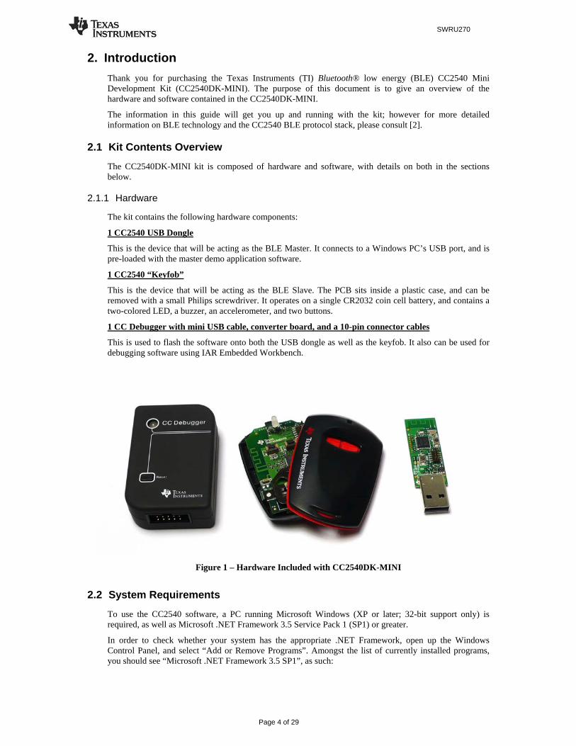
The kit contains the following hardware components:
1 CC2540 USB Dongle
This is the device that will be acting as the BLE Master. It connects to a Windows PC’s USB port, and is pre-loaded with the master demo application software.
1 CC2540 “Keyfob”
This is the device that will be acting as the BLE Slave. The PCB sits inside a plastic case, and can be removed with a small Philips screwdriver. It operates on a single CR2032 coin cell battery, and contains a two-colored LED, a buzzer, an accelerometer, and two buttons.
1 CC Debugger with mini USB cable, converter board, and a 10-pin connector cables
This is used to flash the software onto both the USB dongle as well as the keyfob. It also can be used for debugging software using IAR Embedded Workbench.
Figure 1 – Hardware Included with CC2540DK-MINI
2.2 System Requirements
To use the CC2540 software, a PC running Microsoft Windows (XP or later; 32-bit support only) is required, as well as Microsoft .NET Framework 3.5 Service Pack 1 (SP1) or greater.
In order to check whether your system has the appropriate .NET Framework, open up the Windows Control Panel, and select “Add or Remove Programs”. Amongst the list of currently installed programs, you should see “Microsoft .NET Framework 3.5 SP1”, as such:

SWRU270
Page 5 of 29
Figure 2
If you do not see it in the list, you can download the framework from Microsoft.
From a hardware standpoint, the Windows PC must contain one free USB port. An additional free USB port is required in order to use the CC Debugger and the USB Dongle simultaneously.
IAR Embedded Workbench for 8051 development environment is required in order to make changes to the keyfob software. More information on IAR can be found in [1].
For the keyfob, a small Philips screwdriver (not included in the kit) is required to open up the plastic case, and a CR2032 coin cell battery (included in the kit) is required for power.

SWRU270
Page 6 of 29
3. Getting Started This section describes how to set up the software and get started with the CC2540 Mini Development Kit. It is assumed that the instructions found in [1] (a printed copy of the quick start guide is included with the kit) have already been completed, with both the keyfob and the dongle having been programmed with the latest hex files. In addition, this section assumes that the latest version of the CC2540 BLE software (v1.0 as of the release of this document) has been installed. The latest BLE software can be downloaded at www.ti.com/blestack.
3.1 Associate Driver with USB Dongle
After the software installation is complete, the USB Dongle driver must be associated with the device in order to use the demo application. To associate the USB Dongle driver, first you must connect the USB Dongle to the PC’s USB port, or to a USB hub that connects to the PC.
The first time that the dongle is connected to the PC, a message will pop-up, indicating that Windows does not recognize the device.
Figure 3
When prompted whether to use Windows Update search for software, select “No, not this time” and press the “Next” button. On the next screen, select the option “Install from a list or specific location (Advanced)”, and press the “Next” button:
Figure 4
On the next screen, click the checkbox labeled “Include this location in the search:”, and click the “Browse” button. Select the following directory (assuming the default installation path was used):
C:\Texas Instruments\BLE-CC2540\Accessories\Drivers

SWRU270
Page 7 of 29
Figure 5
Click the “Next” button. This should install the driver. It will take a few seconds for the file to load. If the installation was successful, you should see the screen to the below. Click the “Finish” button to complete the installation.
Figure 6
3.2 Determining the COM Port
Once the driver is installed, you need to determine which COM port Windows has assigned to the USB Dongle. After you have completed the USB Dongle driver association in section 3.1, right-click on the “My Computer” icon on your desktop and select “Properties”:
Figure 7
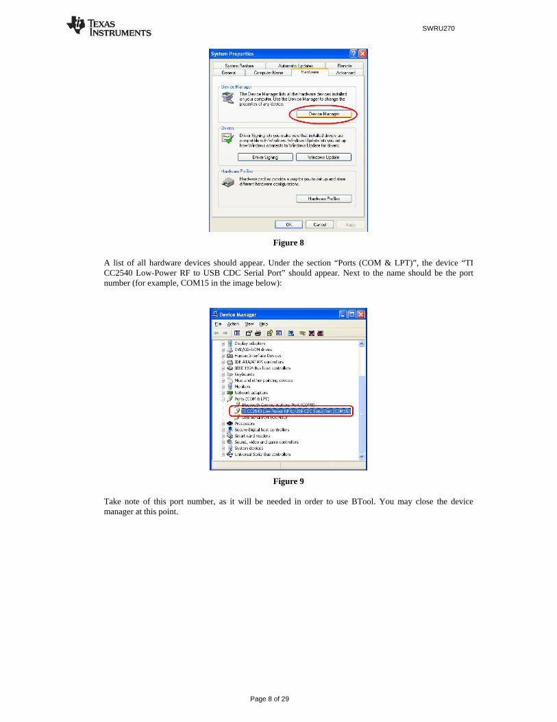
The “System Properties” window should open up. Under the “Hardware” tab, select “Device Manager”:
SWRU270
Page 8 of 29
Figure 8
A list of all hardware devices should appear. Under the section “Ports (COM & LPT)”, the device “TI CC2540 Low-Power RF to USB CDC Serial Port” should appear. Next to the name should be the port number (for example, COM15 in the image below):
Figure 9
Take note of this port number, as it will be needed in order to use BTool. You may close the device manager at this point.
SWRU270
Page 9 of 29
4. Using BTool BTool is a PC Application that allows a user to form a connection between two BLE devices. BTool works by communicating with the CC2540 by means of HCI vendor specific commands. The USB Dongle software (when running the HostTestRelease project) and driver create a virtual serial port over the USB interface. BTool, running on the PC, communicates with the USB Dongle through this virtual serial port.
More information on the HCI interface, as well as details on the HCI vendor specific commands that are used by the CC2540, can be found in [3].
4.1 Starting the Application
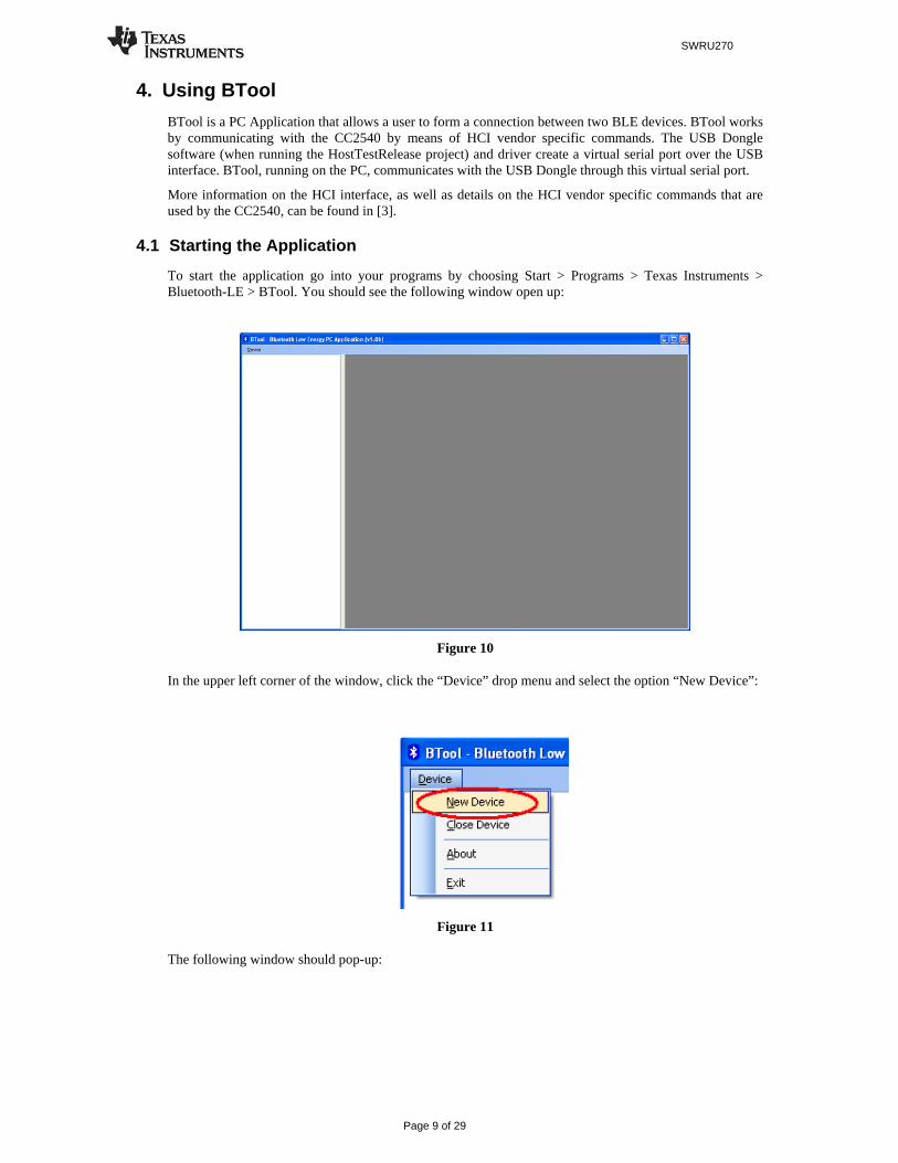
To start the application go into your programs by choosing Start > Programs > Texas Instruments > Bluetooth-LE > BTool. You should see the following window open up:
Figure 10
In the upper left corner of the window, click the “Device” drop menu and select the option “New Device”:
Figure 11
The following window should pop-up:

SWRU270
Page 10 of 29
Figure 12
If using the USB Dongle, set the “Port” value to the COM port of the USB Dongle from step 1. For the other settings, use the default values as shown in Figure 12. Press “OK” to connect to the board. The following screen will appear:
Figure 13
This screen indicates that you are now connected to the USB Dongle. The screen is divided up into a few sections: the left sidebar contains information on the USB Dongle’s status. The left side of the sub-window contains a log of all messages sent from the PC to the dongle and received by the PC from the dongle. The right side of the sub-window contains a GUI for control of the USB Dongle.
4.2 Creating a BLE Connection between USB Dongle and Keyfob
At this point the USB Dongle (central) is ready to discover other BLE devices that are advertising. At this time you will want to insert the battery (or remove and re-insert the battery to reset the device) into the keyfob (peripheral).
4.2.1 Making the Keyfob Discoverable
When the keyfob powers up, it will not immediately go into a discoverable state. To enable advertising and make the keyfob discoverable, press the right-hand button on the keyfob once. This will turn advertisements on; making the device discoverable for 30 seconds (this value is defined in [4]). After that time, the device will return to standby mode. To make the device discoverable again, simply press the button once again.

SWRU270
Page 11 of 29
Figure 14
4.2.2 Scanning for Devices
Press the “Scan” button under the “Discover / Connect” tab:
Figure 15
The USB Dongle will begin search for other BLE devices. As devices are found, the log on the left side of the screen will display the devices discovered. After 10 seconds, the device discovery process will complete, and the USB Dongle will stop scanning. A summary of all the scanned devices will be displayed in the log window. In the example in Figure 16, one peripheral device was discovered while scanning. If you do not want to wait through the full 10 seconds of scanning, the “Cancel” button can be pressed alternatively, which will stop the device discovery process. The address of any scanned devices will appear in the “Slave BDA” section of the “Link Control” section in the bottom right corner of the sub-window.

SWRU270
Page 12 of 29
Figure 16
4.2.3 Selecting Connection Parameters
Before establishing a connection, you will want to set up the desired connection parameters. The default values of 100ms connection interval, 0 slave latency, and 20000ms supervision timeout should serve as a good starting point; however for different applications you may want to experiment with these values.
Once the desired values have been set, be sure to click the “Set” button; other wise the settings will not be saved. Note that the connection parameters must be set before a connection is established; changing the values and clicking the “Set” button while a connection is active will not change the settings of an active connection. The connection must be terminated and re-established to use the new parameters. (The Bluetooth specification does support connection parameter updates while a connection is active; however this must be done using either an L2CAP connection parameter update request, or using a direct HCI command. More information can be found in [4])
Figure 17
4.2.4 Establishing a Connection
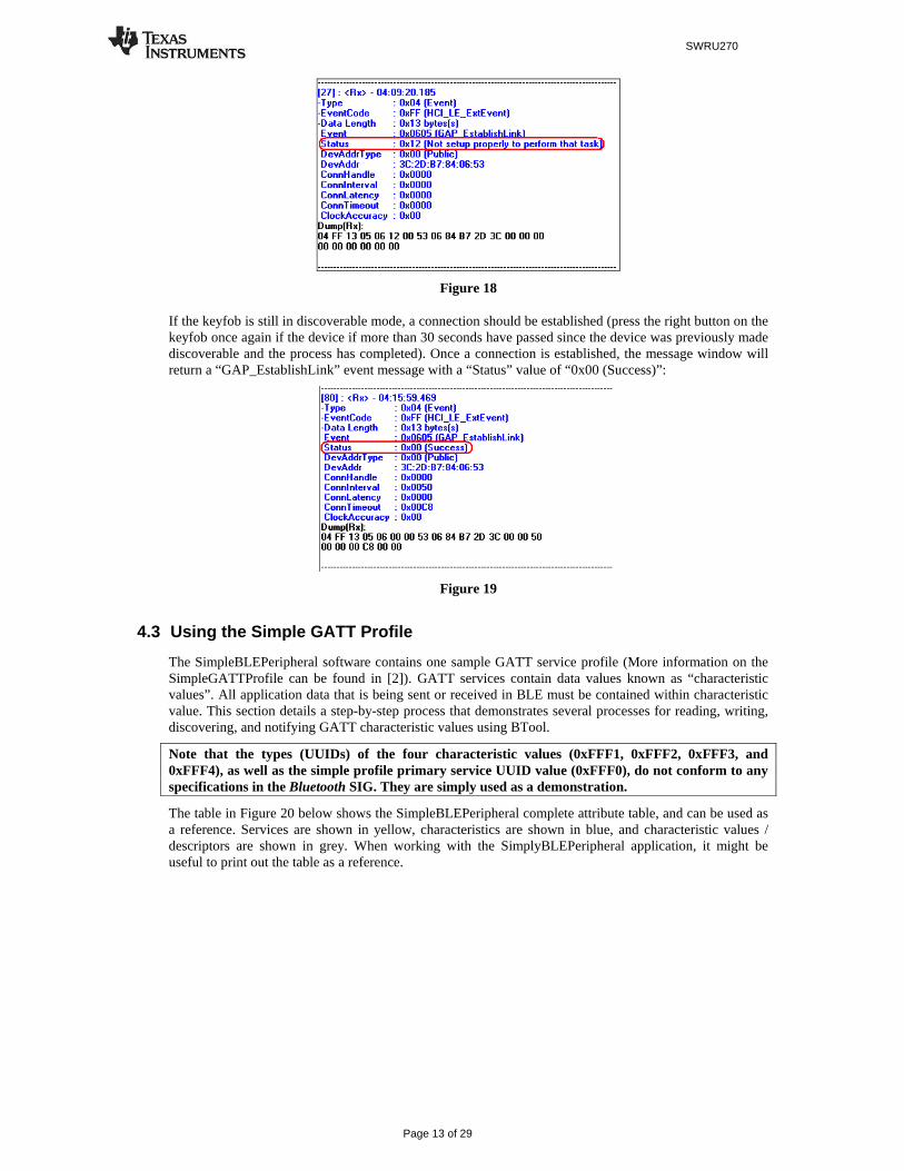
To establish a connection with the keyfob, select the address of the device to connect with, and click the “Establish” button. If the set of connection parameters are invalid (for example, if the combination of connection parameters violates the specification), the message window will return a “GAP_EstablishLink” event message with a “Status” value of “0x12 (Not setup properly to perform that task)”, as shown in Figure 18. The parameters will have to be corrected before a connection can be established.
SWRU270
Page 13 of 29
Figure 18
If the keyfob is still in discoverable mode, a connection should be established (press the right button on the keyfob once again if the device if more than 30 seconds have passed since the device was previously made discoverable and the process has completed). Once a connection is established, the message window will return a “GAP_EstablishLink” event message with a “Status” value of “0x00 (Success)”:
Figure 19
4.3 Using the Simple GATT Profile
The SimpleBLEPeripheral software contains one sample GATT service profile (More information on the SimpleGATTProfile can be found in [2]). GATT services contain data values known as “characteristic values”. All application data that is being sent or received in BLE must be contained within characteristic value. This section details a step-by-step process that demonstrates several processes for reading, writing, discovering, and notifying GATT characteristic values using BTool.
Note that the types (UUIDs) of the four characteristic values (0xFFF1, 0xFFF2, 0xFFF3, and 0xFFF4), as well as the simple profile primary service UUID value (0xFFF0), do not conform to any specifications in the Bluetooth SIG. They are simply used as a demonstration.
The table in Figure 20 below shows the SimpleBLEPeripheral complete attribute table, and can be used as a reference. Services are shown in yellow, characteristics are shown in blue, and characteristic values / descriptors are shown in grey. When working with the SimplyBLEPeripheral application, it might be useful to print out the table as a reference.

SWRU270
Page 14 of 29
Figure 20
4.3.1 Reading a Characteristic Value by UUID
The first characteristic of the SimpleGATTProfile service has both read and write permissions, and has a UUID of 0xFFF1. The simplest way to read its value is to use the “Read Characteristic by UUID” sub-
SWRU270
Page 15 of 29
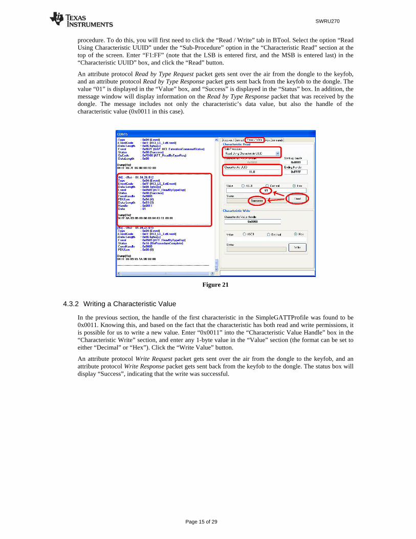
procedure. To do this, you will first need to click the “Read / Write” tab in BTool. Select the option “Read Using Characteristic UUID” under the “Sub-Procedure” option in the “Characteristic Read” section at the top of the screen. Enter “F1:FF” (note that the LSB is entered first, and the MSB is entered last) in the “Characteristic UUID” box, and click the “Read” button.
An attribute protocol Read by Type Request packet gets sent over the air from the dongle to the keyfob, and an attribute protocol Read by Type Response packet gets sent back from the keyfob to the dongle. The value “01” is displayed in the “Value” box, and “Success” is displayed in the “Status” box. In addition, the message window will display information on the Read by Type Response packet that was received by the dongle. The message includes not only the characteristic’s data value, but also the handle of the characteristic value (0x0011 in this case).
Figure 21
4.3.2 Writing a Characteristic Value
In the previous section, the handle of the first characteristic in the SimpleGATTProfile was found to be 0x0011. Knowing this, and based on the fact that the characteristic has both read and write permissions, it is possible for us to write a new value. Enter “0x0011” into the “Characteristic Value Handle” box in the “Characteristic Write” section, and enter any 1-byte value in the “Value” section (the format can be set to either “Decimal” or “Hex”). Click the “Write Value” button.
An attribute protocol Write Request packet gets sent over the air from the dongle to the keyfob, and an attribute protocol Write Response packet gets sent back from the keyfob to the dongle. The status box will display “Success”, indicating that the write was successful.

SWRU270
Page 16 of 29
Figure 22
4.3.3 Reading a Characteristic Value by Handle
After writing a new value to the first characteristic in the profile, we can read the value back to verify the write. This time, instead of reading the value by its UUID, the value will be read by its handle. Select the option “Read Characteristic Value / Descriptor” under the “Sub-Procedure” option in the “Characteristic Read” section. Enter “0x0011” in the “Characteristic Value Handle” box, and click the “Read” button.
An attribute protocol Read Request packet gets sent over the air from the dongle to the keyfob, and an attribute protocol Read Response packet gets sent back from the keyfob to the dongle. The new value is displayed in the “Value” box, and “Success” is displayed in the “Status” box. This value should match the value that was written in the previous step.
Figure 23
4.3.4 Discovering a Characteristic by UUID
The next thing to do is to discover a characteristic by its UUID. By doing this, we will not only get the handle of the UUID, but we will also get the properties of the characteristic. The UUID of the second characteristic in the SimpleGATTProfile is 0xFFF2. Select the option “Discover Characteristic by UUID”
SWRU270
Page 17 of 29
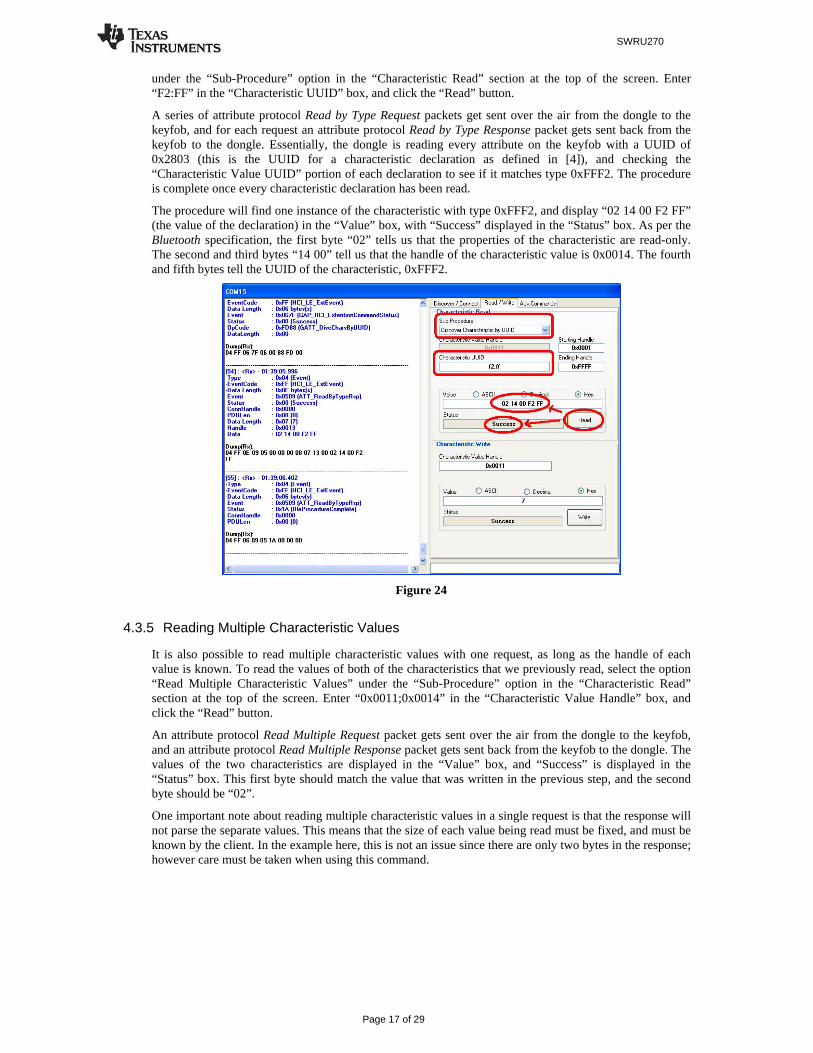
under the “Sub-Procedure” option in the “Characteristic Read” section at the top of the screen. Enter “F2:FF” in the “Characteristic UUID” box, and click the “Read” button.
A series of attribute protocol Read by Type Request packets get sent over the air from the dongle to the keyfob, and for each request an attribute protocol Read by Type Response packet gets sent back from the keyfob to the dongle. Essentially, the dongle is reading every attribute on the keyfob with a UUID of 0x2803 (this is the UUID for a characteristic declaration as defined in [4]), and checking the “Characteristic Value UUID” portion of each declaration to see if it matches type 0xFFF2. The procedure is complete once every characteristic declaration has been read.
The procedure will find one instance of the characteristic with type 0xFFF2, and display “02 14 00 F2 FF” (the value of the declaration) in the “Value” box, with “Success” displayed in the “Status” box. As per the Bluetooth specification, the first byte “02” tells us that the properties of the characteristic are read-only. The second and third bytes “14 00” tell us that the handle of the characteristic value is 0x0014. The fourth and fifth bytes tell the UUID of the characteristic, 0xFFF2.
Figure 24
4.3.5 Reading Multiple Characteristic Values
It is also possible to read multiple characteristic values with one request, as long as the handle of each value is known. To read the values of both of the characteristics that we previously read, select the option “Read Multiple Characteristic Values” under the “Sub-Procedure” option in the “Characteristic Read” section at the top of the screen. Enter “0x0011;0x0014” in the “Characteristic Value Handle” box, and click the “Read” button.
An attribute protocol Read Multiple Request packet gets sent over the air from the dongle to the keyfob, and an attribute protocol Read Multiple Response packet gets sent back from the keyfob to the dongle. The values of the two characteristics are displayed in the “Value” box, and “Success” is displayed in the “Status” box. This first byte should match the value that was written in the previous step, and the second byte should be “02”.
One important note about reading multiple characteristic values in a single request is that the response will not parse the separate values. This means that the size of each value being read must be fixed, and must be known by the client. In the example here, this is not an issue since there are only two bytes in the response; however care must be taken when using this command.

SWRU270
Page 18 of 29
Figure 25
4.3.6 Enabling Notifications
In BLE, it is possible for a GATT server device to “push” characteristic value data out to a client device, without being prompted with a read request. This process is called a “characteristic value notification”. Notifications are useful in that they allow a device in a BLE connection to send out as much or as little data as required at any point in time. In addition, since no request from the client is required, the overhead is reduced and the data is transmitted more efficiently. The SimpleBLEPeripheral software contains an example in which notifications can be demonstrated.
The third characteristic in the SimpleGATTProfile has write-only properties, while the fourth characteristic in the profile has notify-only properties. Every five seconds, the SimpleBLEPeripheral application will take the value of the third characteristic and copy it into the fourth characteristic. Each time the fourth characteristic value gets set by the application, the profile will check to see if notifications are enabled. If they are enabled, the profile will send a notification of the value to the client device.
Before notifications can be enabled, the handle of the fourth characteristic must be found. This can be done by using the “Discover Characteristic by UUID” process (see section 4.3.4), with the UUID value set to “F4:FF”. The procedure will find one instance of the characteristic with type 0xFFF4, and display “10 1A 00 F4 FF” (the value of the declaration) in the “Value” box, with “Success” displayed in the “Status” box. As per the Bluetooth specification, the first byte “10” tells us that the properties of the characteristic are notify-only. The second and third bytes “1A 00” tell us that the handle of the characteristic value is 0x001A. The fourth and fifth bytes tell the UUID of the characteristic, 0xFFF4.
In order to enable notifications, the client device must write a value of 0x0001 to the client characteristic configuration descriptor for the particular characteristic. The handle for the characteristic configuration descriptor immediately follows the characteristic value’s handle. Therefore, a value of 0x0001 must be written to handle 0x001B. Enter “0x001B” into the “Characteristic Value Handle” box in the “Characteristic Write” section, and enter “01:00” in the “Value” section (the format can be set to either “Decimal” or “Hex”; note that the LSB is entered first, and the MSB is entered last). Click the “Write Value” button. The status box will display “Success”, indicating that the write was successful.
Every five seconds, an attribute protocol Handle Value Notification packet gets sent from the keyfob to the dongle. With each notification, the value of the characteristic at handle is displayed in the log window.

SWRU270
Page 19 of 29
Figure 26
The value should be “03” in each notification, since it is copied from the value of the third characteristic in the profile (which has a default value of 3). The third characteristic has write-only properties, and therefore can be changed. By following the procedure from section 4.3.4, the handle of the third characteristic can be found to be 0x0017. By following the procedure from section 4.3.2, a new value can be written to handle 0x0017. Once this is done, the value of the fourth characteristic will change. This new value is reflected in the incoming notification messages.
Figure 27
4.4 Using the Simple Keys GATT Profile
The simple keys profile on the keyfob allows the device to send notifications of key presses and releases to a central device. The UUID of the simple keys data characteristic value is 0xFFE1.
Using the same discovery process as before with the “Discover Characteristic by UUID” command, it can be determined that the handle of the simple keys data is 0x001F. Like the fourth characteristic value in the simple GATT profile, the simple keys data is a “configurable” characteristic, in that the client device can configure the server to send notifications of the characteristic value. The handle immediately following the characteristic value is the “characteristic configuration”.
SWRU270
Page 20 of 29
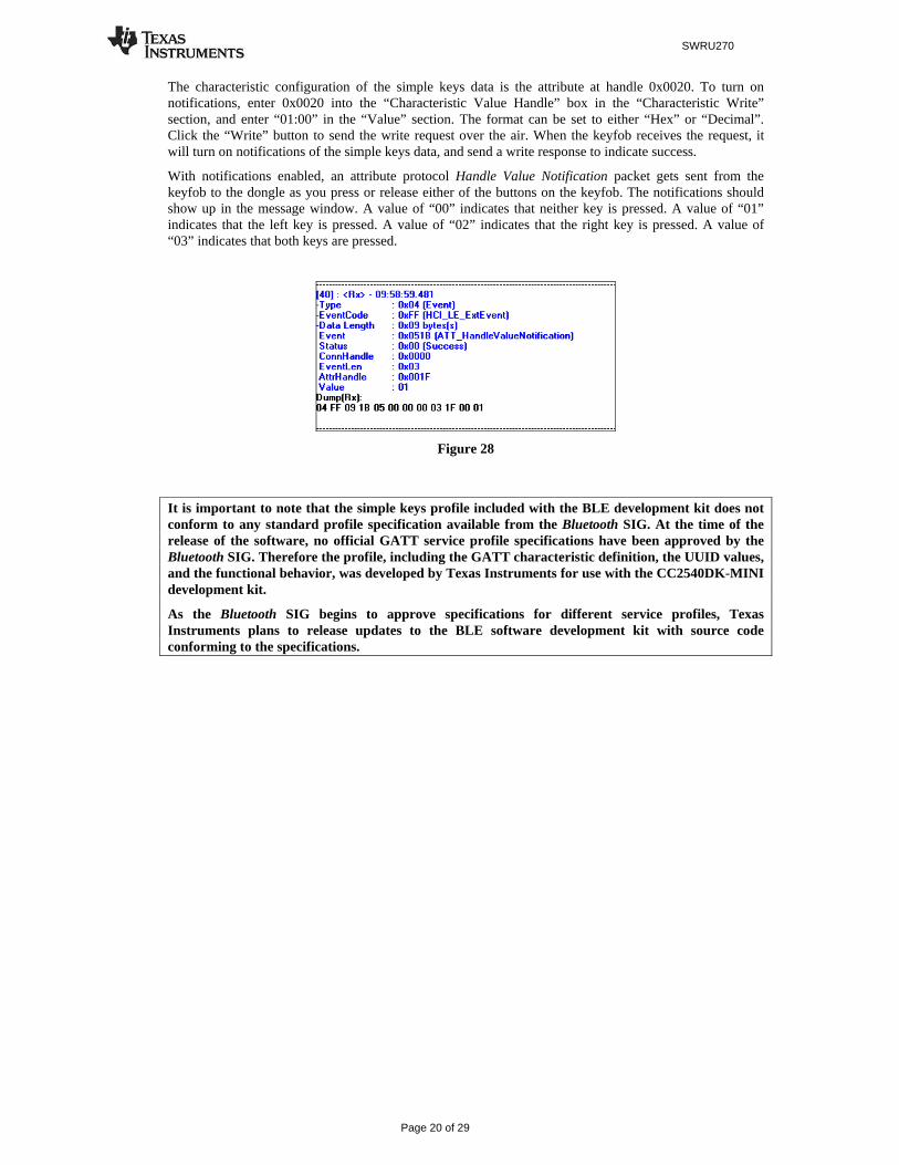
The characteristic configuration of the simple keys data is the attribute at handle 0x0020. To turn on notifications, enter 0x0020 into the “Characteristic Value Handle” box in the “Characteristic Write” section, and enter “01:00” in the “Value” section. The format can be set to either “Hex” or “Decimal”. Click the “Write” button to send the write request over the air. When the keyfob receives the request, it will turn on notifications of the simple keys data, and send a write response to indicate success.
With notifications enabled, an attribute protocol Handle Value Notification packet gets sent from the keyfob to the dongle as you press or release either of the buttons on the keyfob. The notifications should show up in the message window. A value of “00” indicates that neither key is pressed. A value of “01” indicates that the left key is pressed. A value of “02” indicates that the right key is pressed. A value of “03” indicates that both keys are pressed.
Figure 28
It is important to note that the simple keys profile included with the BLE development kit does not conform to any standard profile specification available from the Bluetooth SIG. At the time of the release of the software, no official GATT service profile specifications have been approved by the Bluetooth SIG. Therefore the profile, including the GATT characteristic definition, the UUID values, and the functional behavior, was developed by Texas Instruments for use with the CC2540DK-MINI development kit.
As the Bluetooth SIG begins to approve specifications for different service profiles, Texas Instruments plans to release updates to the BLE software development kit with source code conforming to the specifications.
SWRU270
Page 21 of 29
5. Programming / Debugging the CC2540 The CC Debugger included with the CC2540DK-MINI kit allows for debugging using IAR Embedded Workbench, as well as for reading and writing hex files to the CC2540 flash memory using the SmartRF Flash Programmer software. SmartRF Flash Programmer also has the capability to change the IEEE address of the CC2540 device. The BLE software development kit includes hex files for both the USB Dongle as well as the keyfob. This section details the hardware setup when using the CC Debugger, as well as information on using SmartRF Flash Programmer. Information on using IAR Embedded Workbench for debugging can be found in [2]
5.1 Hardware Setup for Keyfob
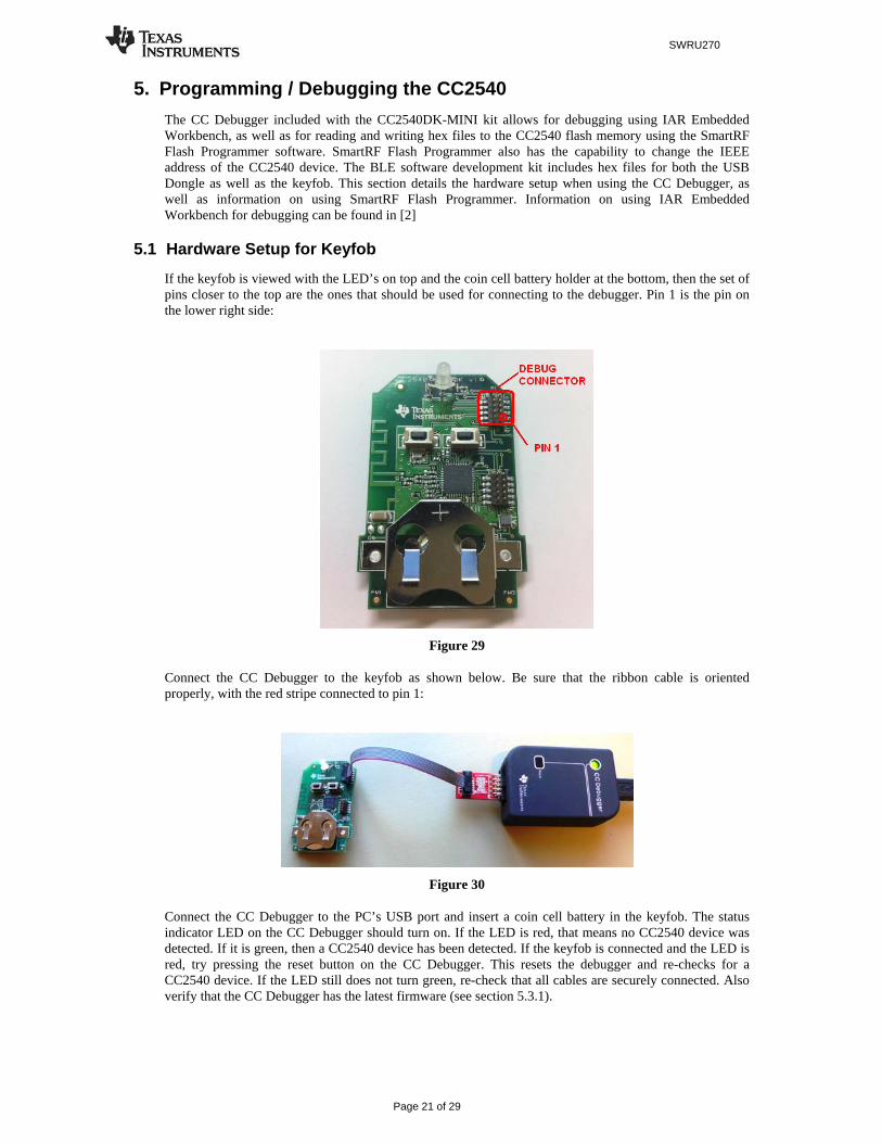
If the keyfob is viewed with the LED’s on top and the coin cell battery holder at the bottom, then the set of pins closer to the top are the ones that should be used for connecting to the debugger. Pin 1 is the pin on the lower right side:
Figure 29
Connect the CC Debugger to the keyfob as shown below. Be sure that the ribbon cable is oriented properly, with the red stripe connected to pin 1:
Figure 30
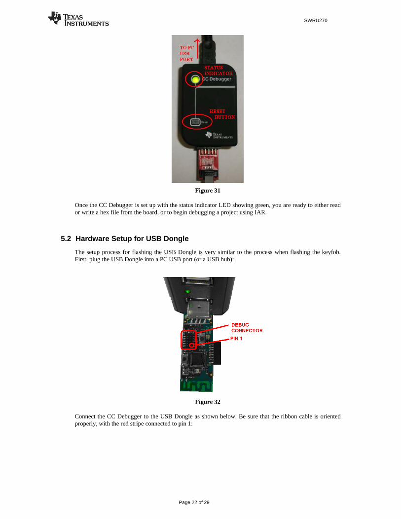
Connect the CC Debugger to the PC’s USB port and insert a coin cell battery in the keyfob. The status indicator LED on the CC Debugger should turn on. If the LED is red, that means no CC2540 device was detected. If it is green, then a CC2540 device has been detected. If the keyfob is connected and the LED is red, try pressing the reset button on the CC Debugger. This resets the debugger and re-checks for a CC2540 device. If the LED still does not turn green, re-check that all cables are securely connected. Also verify that the CC Debugger has the latest firmware (see section 5.3.1).
SWRU270
Page 22 of 29
Figure 31
Once the CC Debugger is set up with the status indicator LED showing green, you are ready to either read or write a hex file from the board, or to begin debugging a project using IAR.
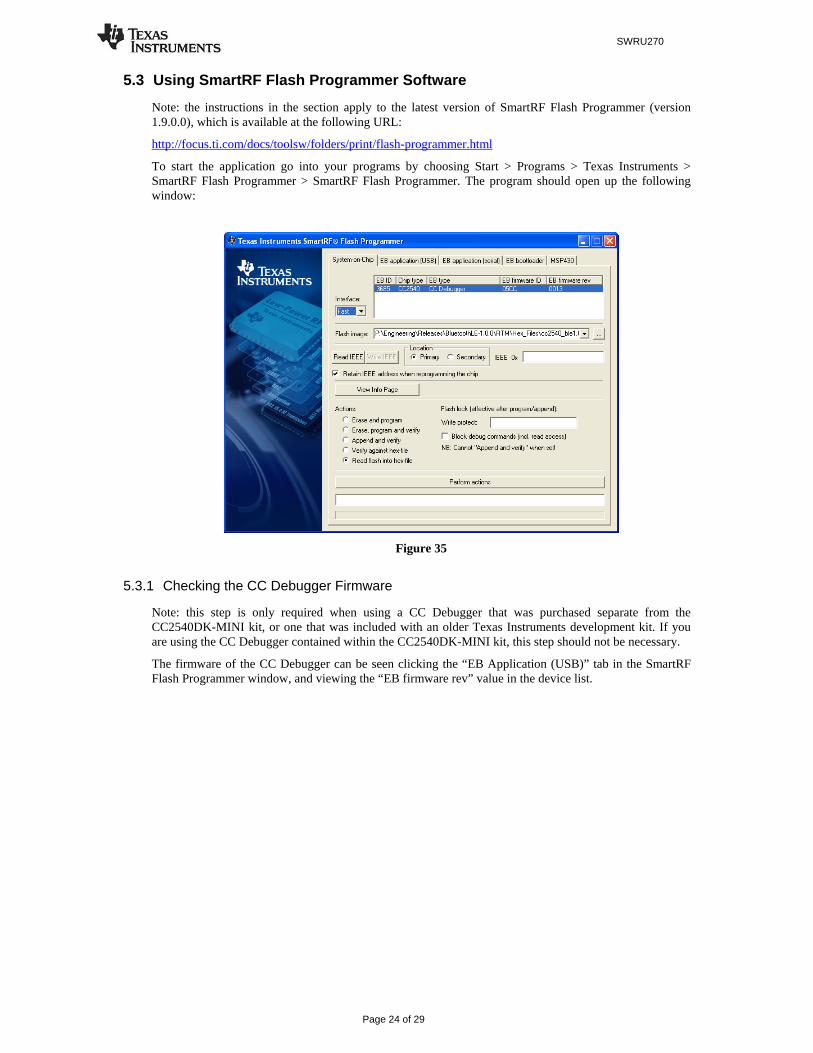
5.2 Hardware Setup for USB Dongle
The setup process for flashing the USB Dongle is very similar to the process when flashing the keyfob. First, plug the USB Dongle into a PC USB port (or a USB hub):
Figure 32
Connect the CC Debugger to the USB Dongle as shown below. Be sure that the ribbon cable is oriented properly, with the red stripe connected to pin 1:

SWRU270
Page 23 of 29
Figure 33
Connect the CC Debugger to the PC USB port. The status indicator LED on the CC Debugger should turn on. If the LED is red, that means no CC2540 device was detected. If it is green, then a CC2540 device has been detected. If the USB Dongle is connected and the LED is red, try pressing the reset button on the CC Debugger. This resets the debugger and re-checks for a CC2540 device. If the LED still does not turn green, re-check that all cables are securely connected.
Figure 34
Once the CC Debugger status LED is showing green, you are ready to use IAR to debug or to read or write a hex file from/to the USB Dongle.
SWRU270
Page 24 of 29
5.3 Using SmartRF Flash Programmer Software
Note: the instructions in the section apply to the latest version of SmartRF Flash Programmer (version 1.9.0.0), which is available at the following URL:
http://focus.ti.com/docs/toolsw/folders/print/flash-programmer.html
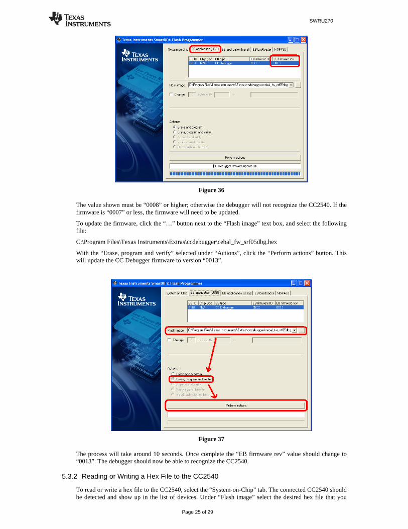
To start the application go into your programs by choosing Start > Programs > Texas Instruments > SmartRF Flash Programmer > SmartRF Flash Programmer. The program should open up the following window:
Figure 35
5.3.1 Checking the CC Debugger Firmware
Note: this step is only required when using a CC Debugger that was purchased separate from the CC2540DK-MINI kit, or one that was included with an older Texas Instruments development kit. If you are using the CC Debugger contained within the CC2540DK-MINI kit, this step should not be necessary.
The firmware of the CC Debugger can be seen clicking the “EB Application (USB)” tab in the SmartRF Flash Programmer window, and viewing the “EB firmware rev” value in the device list.
SWRU270
Page 25 of 29
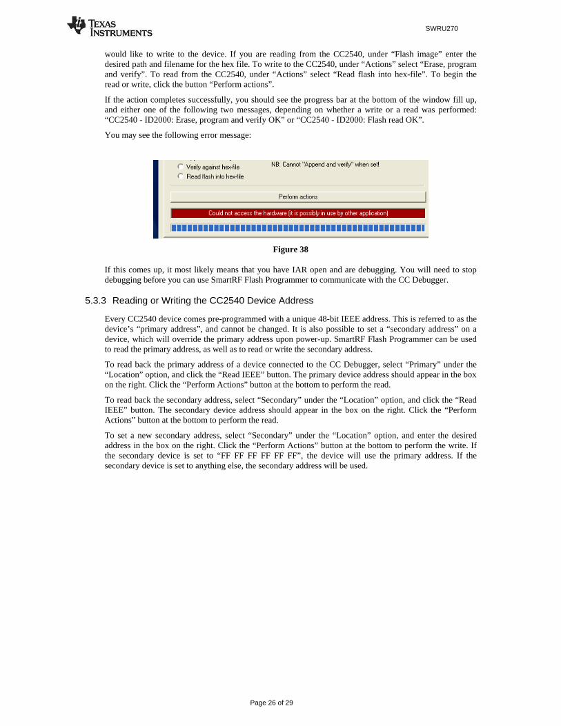
Figure 36
The value shown must be “0008” or higher; otherwise the debugger will not recognize the CC2540. If the firmware is “0007” or less, the firmware will need to be updated.
To update the firmware, click the “…” button next to the “Flash image” text box, and select the following file:
C:\Program Files\Texas Instruments\Extras\ccdebugger\cebal_fw_srf05dbg.hex
With the “Erase, program and verify” selected under “Actions”, click the “Perform actions” button. This will update the CC Debugger firmware to version “0013”.
Figure 37
The process will take around 10 seconds. Once complete the “EB firmware rev” value should change to “0013”. The debugger should now be able to recognize the CC2540.
5.3.2 Reading or Writing a Hex File to the CC2540
To read or write a hex file to the CC2540, select the “System-on-Chip” tab. The connected CC2540 should be detected and show up in the list of devices. Under “Flash image” select the desired hex file that you
SWRU270
Page 26 of 29
would like to write to the device. If you are reading from the CC2540, under “Flash image” enter the desired path and filename for the hex file. To write to the CC2540, under “Actions” select “Erase, program and verify”. To read from the CC2540, under “Actions” select “Read flash into hex-file”. To begin the read or write, click the button “Perform actions”.
If the action completes successfully, you should see the progress bar at the bottom of the window fill up, and either one of the following two messages, depending on whether a write or a read was performed: “CC2540 - ID2000: Erase, program and verify OK” or “CC2540 - ID2000: Flash read OK”.
You may see the following error message:
Figure 38
If this comes up, it most likely means that you have IAR open and are debugging. You will need to stop debugging before you can use SmartRF Flash Programmer to communicate with the CC Debugger.
5.3.3 Reading or Writing the CC2540 Device Address
Every CC2540 device comes pre-programmed with a unique 48-bit IEEE address. This is referred to as the device’s “primary address”, and cannot be changed. It is also possible to set a “secondary address” on a device, which will override the primary address upon power-up. SmartRF Flash Programmer can be used to read the primary address, as well as to read or write the secondary address.
To read back the primary address of a device connected to the CC Debugger, select “Primary” under the “Location” option, and click the “Read IEEE” button. The primary device address should appear in the box on the right. Click the “Perform Actions” button at the bottom to perform the read.
To read back the secondary address, select “Secondary” under the “Location” option, and click the “Read IEEE” button. The secondary device address should appear in the box on the right. Click the “Perform Actions” button at the bottom to perform the read.
To set a new secondary address, select “Secondary” under the “Location” option, and enter the desired address in the box on the right. Click the “Perform Actions” button at the bottom to perform the write. If the secondary device is set to “FF FF FF FF FF FF”, the device will use the primary address. If the secondary device is set to anything else, the secondary address will be used.

SWRU270
Page 27 of 29
Figure 39
Note that every time you re-program the device using SmartRF Flash Programmer, the secondary address of the device will get set to FF:FF:FF:FF:FF:FF. This can be avoided by selecting the option “Retain IEEE address when reprogramming the chip”. A similar situation exists when a device is reprogrammed through IAR Embedded Workbench, in that the secondary address will get set to FF:FF:FF:FF:FF:FF each time. To avoid this, the IAR option “Retain unchanged memory”, under the “Debugger” > “Texas Instruments” project option can be selected.
Figure 40
SWRU270
Page 28 of 29
6. Additional Projects at ti.com In addition to the applications previously mentioned in this document, here are two other additional projects available on Texas Instruments’ web page for use with the CC2540 Mini Development Kit.
6.1 KeyFobDemo Project
The KeyFobDemo project is an application designed specifically for use with the keyfob board included as part of the CC2540 Mini Development Kit. It implements a BLE peripheral device similar to the SimpleBLEPeripheral project; however it makes more use of the hardware on the board such as the buzzer, accelerometer, and LEDs.
The KeyFobDemo downloadable source code and project files, along with documentation, can be found on the Texas Instruments wiki page at the following link:
http://processors.wiki.ti.com/index.php/Category:KeyFobDemo
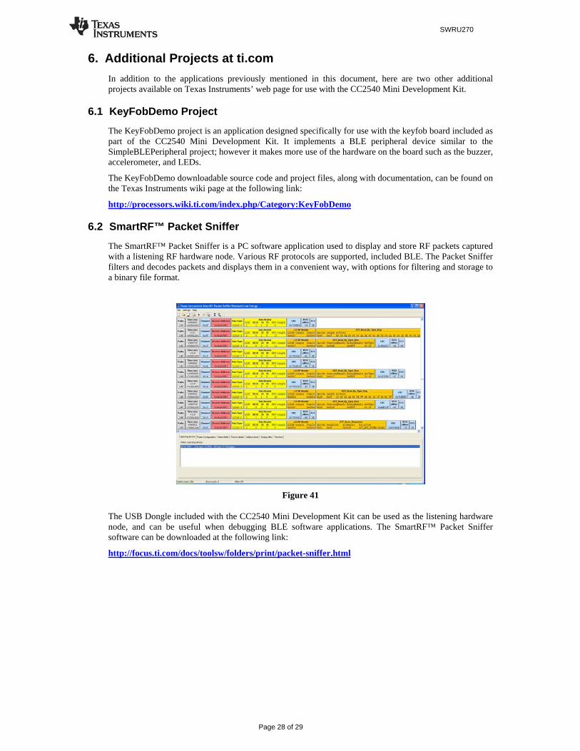
6.2 SmartRF™ Packet Sniffer
The SmartRF™ Packet Sniffer is a PC software application used to display and store RF packets captured with a listening RF hardware node. Various RF protocols are supported, included BLE. The Packet Sniffer filters and decodes packets and displays them in a convenient way, with options for filtering and storage to a binary file format.
Figure 41
The USB Dongle included with the CC2540 Mini Development Kit can be used as the listening hardware node, and can be useful when debugging BLE software applications. The SmartRF™ Packet Sniffer software can be downloaded at the following link:
http://focus.ti.com/docs/toolsw/folders/print/packet-sniffer.html

SWRU270
Page 29 of 29
7. General Information
7.1 Document History
Revision Date Description/Changes
1.0 2010-10-08 Initial release
1.0.1 2010-11-29 Added information about packet sniffer and KeyFobDemo application

IMPORTANT NOTICE
Texas Instruments Incorporated and its subsidiaries (TI) reserve the right to make corrections, modifications, enhancements, improvements,and other changes to its products and services at any time and to discontinue any product or service without notice. Customers shouldobtain the latest relevant information before placing orders and should verify that such information is current and complete. All products aresold subject to TI’s terms and conditions of sale supplied at the time of order acknowledgment.
TI warrants performance of its hardware products to the specifications applicable at the time of sale in accordance with TI’s standardwarranty. Testing and other quality control techniques are used to the extent TI deems necessary to support this warranty. Except wheremandated by government requirements, testing of all parameters of each product is not necessarily performed.
TI assumes no liability for applications assistance or customer product design. Customers are responsible for their products andapplications using TI components. To minimize the risks associated with customer products and applications, customers should provideadequate design and operating safeguards.
TI does not warrant or represent that any license, either express or implied, is granted under any TI patent right, copyright, mask work right,or other TI intellectual property right relating to any combination, machine, or process in which TI products or services are used. Informationpublished by TI regarding third-party products or services does not constitute a license from TI to use such products or services or awarranty or endorsement thereof. Use of such information may require a license from a third party under the patents or other intellectualproperty of the third party, or a license from TI under the patents or other intellectual property of TI.
Reproduction of TI information in TI data books or data sheets is permissible only if reproduction is without alteration and is accompaniedby all associated warranties, conditions, limitations, and notices. Reproduction of this information with alteration is an unfair and deceptivebusiness practice. TI is not responsible or liable for such altered documentation. Information of third parties may be subject to additionalrestrictions.
Resale of TI products or services with statements different from or beyond the parameters stated by TI for that product or service voids allexpress and any implied warranties for the associated TI product or service and is an unfair and deceptive business practice. TI is notresponsible or liable for any such statements.
TI products are not authorized for use in safety-critical applications (such as life support) where a failure of the TI product would reasonablybe expected to cause severe personal injury or death, unless officers of the parties have executed an agreement specifically governingsuch use. Buyers represent that they have all necessary expertise in the safety and regulatory ramifications of their applications, andacknowledge and agree that they are solely responsible for all legal, regulatory and safety-related requirements concerning their productsand any use of TI products in such safety-critical applications, notwithstanding any applications-related information or support that may beprovided by TI. Further, Buyers must fully indemnify TI and its representatives against any damages arising out of the use of TI products insuch safety-critical applications.
TI products are neither designed nor intended for use in military/aerospace applications or environments unless the TI products arespecifically designated by TI as military-grade or "enhanced plastic." Only products designated by TI as military-grade meet militaryspecifications. Buyers acknowledge and agree that any such use of TI products which TI has not designated as military-grade is solely atthe Buyer's risk, and that they are solely responsible for compliance with all legal and regulatory requirements in connection with such use.
TI products are neither designed nor intended for use in automotive applications or environments unless the specific TI products aredesignated by TI as compliant with ISO/TS 16949 requirements. Buyers acknowledge and agree that, if they use any non-designatedproducts in automotive applications, TI will not be responsible for any failure to meet such requirements.
Following are URLs where you can obtain information on other Texas Instruments products and application solutions:
Products Applications
Amplifiers amplifier.ti.com Audio www.ti.com/audio
Data Converters dataconverter.ti.com Automotive www.ti.com/automotive
DLP® Products www.dlp.com Communications and www.ti.com/communicationsTelecom
DSP dsp.ti.com Computers and www.ti.com/computersPeripherals
Clocks and Timers www.ti.com/clocks Consumer Electronics www.ti.com/consumer-apps
Interface interface.ti.com Energy www.ti.com/energy
Logic logic.ti.com Industrial www.ti.com/industrial
Power Mgmt power.ti.com Medical www.ti.com/medical
Microcontrollers microcontroller.ti.com Security www.ti.com/security
RFID www.ti-rfid.com Space, Avionics & www.ti.com/space-avionics-defenseDefense
RF/IF and ZigBee® Solutions www.ti.com/lprf Video and Imaging www.ti.com/video
Wireless www.ti.com/wireless-apps
Mailing Address: Texas Instruments, Post Office Box 655303, Dallas, Texas 75265Copyright © 2010, Texas Instruments Incorporated