
CC2540 and CC2541 Bluetooth® low energy Software · PDF fileTI CC2540 Bluetooth low energy...
154
CC2540 and CC2541 Bluetooth ® low energy Software Developer’s Reference Guide Literature Number: SWRU271G October 2010 – Revised September 2015
Transcript of CC2540 and CC2541 Bluetooth® low energy Software · PDF fileTI CC2540 Bluetooth low energy...

CC2540 and CC2541 Bluetooth® low energySoftware Developer’s
Reference Guide
Literature Number: SWRU271GOctober 2010–Revised September 2015

Contents
Preface ........................................................................................................................................ 71 Overview............................................................................................................................. 8
1.1 Introduction ................................................................................................................... 81.2 BLE Protocol Stack Basics ................................................................................................. 9
2 The TI BLE Software Development Platform .......................................................................... 112.1 Configurations .............................................................................................................. 112.2 Projects ...................................................................................................................... 142.3 Software Overview ......................................................................................................... 14
3 The Operating System Abstraction Layer (OSAL) ................................................................... 153.1 Task Initialization ........................................................................................................... 163.2 Task Events and Event Processing...................................................................................... 173.3 Heap Manager .............................................................................................................. 183.4 OSAL Messages ........................................................................................................... 18
4 The Application and Profiles................................................................................................ 204.1 Project Overview ........................................................................................................... 204.2 Start-up in main() ........................................................................................................... 224.3 Application Initialization.................................................................................................... 234.4 Event Processing........................................................................................................... 23
4.4.1 Periodic Event ..................................................................................................... 234.4.2 OSAL Messages .................................................................................................. 24
4.5 Callbacks .................................................................................................................... 244.6 Complete Attribute Table .................................................................................................. 254.7 Additional Sample Projects ............................................................................................... 26
5 The BLE Protocol Stack ...................................................................................................... 275.1 Generic Access Profile (GAP) ............................................................................................ 27
5.1.1 Overview............................................................................................................ 275.1.2 GAP Abstraction................................................................................................... 315.1.3 Configuring the GAP Layer ...................................................................................... 31
5.2 GAPRole Task .............................................................................................................. 325.2.1 Peripheral Role .................................................................................................... 325.2.2 Central Role........................................................................................................ 35
5.3 Gap Bond Manager (GAPBondMgr) ..................................................................................... 375.3.1 Overview of BLE Security ........................................................................................ 375.3.2 Using the GapBondMgr Profile .................................................................................. 385.3.3 GAPBondMgr Examples for Various Security Modes ........................................................ 40
5.4 Generic Attribute Profile (GATT) ......................................................................................... 455.4.1 GATT Characteristics and Attributes ........................................................................... 455.4.2 GATT Services and Profile....................................................................................... 475.4.3 GATT Client Abstraction.......................................................................................... 495.4.4 GATT Server Abstraction......................................................................................... 52
5.5 L2CAP ....................................................................................................................... 635.6 HCI ........................................................................................................................... 63
5.6.1 HCI Extension Vendor-Specific Commands ................................................................... 635.6.2 Receiving HCI Extension Events in the Application .......................................................... 63
2 Contents SWRU271G–October 2010–Revised September 2015Submit Documentation Feedback
Copyright © 2010–2015, Texas Instruments Incorporated

www.ti.com
5.7 Library Files ................................................................................................................. 64
6 Drivers .............................................................................................................................. 656.1 ADC .......................................................................................................................... 666.2 AES .......................................................................................................................... 666.3 LCD .......................................................................................................................... 666.4 LED........................................................................................................................... 666.5 KEY .......................................................................................................................... 666.6 DMA.......................................................................................................................... 666.7 UART and SPI .............................................................................................................. 666.8 Other Peripherals........................................................................................................... 676.9 Simple NV (SNV) ........................................................................................................... 67
7 Creating a Custom BLE Application...................................................................................... 687.1 Configuring the BLE Stack ................................................................................................ 687.2 Define BLE Behavior....................................................................................................... 687.3 Define Application Tasks .................................................................................................. 687.4 Configure Hardware Peripherals ......................................................................................... 687.5 Configuring Parameters for Custom Hardware......................................................................... 68
7.5.1 Board File .......................................................................................................... 687.5.2 Adjusting for 32-MHz Crystal Stabilization Time .............................................................. 697.5.3 Setting the Sleep Clock Accuracy............................................................................... 69
7.6 Software Considerations .................................................................................................. 697.6.1 Memory Management for GATT Notifications and Indications .............................................. 697.6.2 Limit Application Processing During BLE Activity ............................................................. 707.6.3 Global Interrupts................................................................................................... 70
8 Development and Debugging ............................................................................................... 718.1 IAR Overview ............................................................................................................... 718.2 Using IAR Embedded Workbench ....................................................................................... 71
8.2.1 Open an Existing Project ......................................................................................... 718.2.2 Project Options, Configurations, and Defined Symbols ...................................................... 728.2.3 Building and Debugging a Project .............................................................................. 778.2.4 Linker Map File .................................................................................................... 79
9 General Information ............................................................................................................ 819.1 Release Notes History ..................................................................................................... 819.2 Document History .......................................................................................................... 94
A GAP API ............................................................................................................................ 95A.1 Commands .................................................................................................................. 95A.2 Configurable Parameters.................................................................................................. 95A.3 Events........................................................................................................................ 98
B GAPRole Peripheral Role API ............................................................................................. 102B.1 Commands ................................................................................................................ 102B.2 Configurable Parameters ................................................................................................ 104B.3 Callbacks................................................................................................................... 105
B.3.1 State Change Callback (pfnStateChange) ................................................................... 105B.3.2 RSSI Callback (pfnRssiRead).................................................................................. 106
C GAPRole Central Role API ................................................................................................. 107C.1 Commands ................................................................................................................ 107C.2 Configurable Parameters ................................................................................................ 111C.3 Callbacks................................................................................................................... 111
C.3.1 RSSI Callback (rssiCB) ......................................................................................... 111C.3.2 Central Event Callback (eventCB)............................................................................. 112
D GATT/ATT API .................................................................................................................. 113
3SWRU271G–October 2010–Revised September 2015 ContentsSubmit Documentation Feedback
Copyright © 2010–2015, Texas Instruments Incorporated

www.ti.com
D.1 Server Commands........................................................................................................ 113D.2 Client Commands......................................................................................................... 114D.3 Return Values ............................................................................................................. 120D.4 Events ...................................................................................................................... 121D.5 GATT Commands and Corresponding ATT Events.................................................................. 123D.6 ATT_ERROR_RSP Error Codes ....................................................................................... 123
E GATTServApp API ............................................................................................................ 125E.1 Commands ................................................................................................................ 125
F GAPBondMgr API ............................................................................................................. 127F.1 Commands ................................................................................................................ 127F.2 Configurable Parameters ................................................................................................ 130F.3 Callbacks................................................................................................................... 131
F.3.1 Passcode Callback (passcodeCB) ............................................................................ 131F.3.2 Pairing State Callback (pairStateCB) ......................................................................... 131
G HCI Extension API ............................................................................................................ 133G.1 Commands ................................................................................................................ 133G.2 Host Error Codes ......................................................................................................... 151
Revision History ........................................................................................................................ 153
4 Contents SWRU271G–October 2010–Revised September 2015Submit Documentation Feedback
Copyright © 2010–2015, Texas Instruments Incorporated

www.ti.com
List of Figures1-1. Bluetooth Smart and Bluetooth Smart Ready Branding Marks ....................................................... 81-2. BLE Protocol Stack .......................................................................................................... 92-1. Single-Device Configuration .............................................................................................. 122-2. Network Processor Configuration ........................................................................................ 133-1. OSAL Task Loop ........................................................................................................... 174-1. Project Files ................................................................................................................. 204-2. SimpleBLEPeripheral Complete Attribute Table ....................................................................... 255-1. GAP State Diagram ........................................................................................................ 275-2. Connection Event and Interval ........................................................................................... 285-3. Slave Latency............................................................................................................... 295-4. GAP Abstraction............................................................................................................ 315-5. Just Works Pairing ......................................................................................................... 405-6. Bonding After Just Works Pairing ........................................................................................ 425-7. Pairing With MITM Authentication........................................................................................ 435-8. GATT Client and Server ................................................................................................... 455-9. simpleGATTProfile Characteristic Table from BTool .................................................................. 475-10. GATT Client Abstraction................................................................................................... 495-11. GATT Server Abstraction.................................................................................................. 525-12. Attribute Table Initialization ............................................................................................... 535-13. Get and Set Profile Parameter Usage................................................................................... 626-1. HAL Drivers ................................................................................................................. 658-1. IAR Embedded Workbench ............................................................................................... 728-2. Project Configurations and Options...................................................................................... 738-3. Project Configurations ..................................................................................................... 738-4. Preprocessor Defined Symbols Settings ................................................................................ 748-5. The buildConfig.h File ..................................................................................................... 758-6. Configuration File Setup................................................................................................... 758-7. Building a Project........................................................................................................... 778-8. Debug Button in IAR ....................................................................................................... 788-9. Target Selection ............................................................................................................ 788-10. IAR Debug Toolbar......................................................................................................... 798-11. Map File in File List ........................................................................................................ 79
5SWRU271G–October 2010–Revised September 2015 List of FiguresSubmit Documentation Feedback
Copyright © 2010–2015, Texas Instruments Incorporated

www.ti.com
List of Tables5-1. GAP Bond Manager Security Terms .................................................................................... 375-2. Supported BLE-Stack Library Configurations........................................................................... 64G-1. Host Error Codes ......................................................................................................... 151
6 List of Tables SWRU271G–October 2010–Revised September 2015Submit Documentation Feedback
Copyright © 2010–2015, Texas Instruments Incorporated

PrefaceSWRU271G–October 2010–Revised September 2015
References
The following references are included with the TI Bluetooth® low energy v1.4.1 stack release.
NOTE: Path and file references in this document assume you have installed the BLE developmentkit software to the path: C:\Texas Instruments\BLE-CC254X-1.4.1\. This path is referred to as$INSTALL$.
1. TI BLE Vendor-Specific HCI Reference Guide,$INSTALL$\Documents\TI_BLE_Vendor_Specific_HCI_Guide.pdf
2. TI CC2540 Bluetooth low energy API Guide, $INSTALL$\Documents\BLE_API_Guide_main.htm3. Advanced Remote Control Quick Start Guide,
$INSTALL$\Documents\TI_CC2541_ARC_Quick_Start_Guide.pdf4. Advanced Remote Control User’s Guide, $INSTALL$\Documents\TI_CC2541_ARC_User_Guide.pdf5. TI CC2540 Bluetooth low energy Sample Applications Guide,
$INSTALL$\Documents\TI_BLE_Sample_Applications_Guide.pdf6. Universal Bootloader (UBL) Guide, $INSTALL$\Documents\Universal Boot Loader for SOC-8051 by
USB-MSD Developer's Guide.pdf7. OSAL API Guide, $INSTALL$\Documents\osal\OSAL API.pdf8. HAL API Guide, $INSTALL$\Documents\hal\HAL API.pdf
Also available for download from TI.com:9. TI CC2540DK-MINI Bluetooth low energy User Guide v1.1 (SWRU270)10. Measuring Power Consumption Application Note (SWRA347)11. CC2541/43/44/45 Peripherals Software Examples (SWRC257)12. CC254x Chip User’s Guide (SWRU191)
Available for download from the Bluetooth Special Interest Group (SIG) website:13. Specification of the Bluetooth System, Covered Core Package version: 4.0 (30-June-2010),
https://www.bluetooth.org/docman/handlers/downloaddoc.ashx?doc_id=22973714. Device Information Service (Bluetooth Specification), version 1.0 (24-May-2011),
https://www.bluetooth.org/docman/handlers/downloaddoc.ashx?doc_id=238689Links
15. TI Bluetooth low energy Wiki-page: www.ti.com/ble-wiki16. Latest stack download: www.ti.com/ble-stack17. Support forum: www.ti.com/ble-forum
BLE Stack, SimpleLink are trademarks of Texas Instruments.Bluetooth Smart is a trademark of Bluetooth SIG.Bluetooth is a registered trademark of Bluetooth SIG.
7SWRU271G–October 2010–Revised September 2015 ReferencesSubmit Documentation Feedback
Copyright © 2010–2015, Texas Instruments Incorporated

Chapter 1SWRU271G–October 2010–Revised September 2015
Overview
The purpose of this document is to give an overview of the TI CC2540 and CC2541 Bluetooth low energy(BLE) software development kit. This document also introduces the BLE standard but should not be usedas a substitute for the complete specification. For more details, see the Specification of the BluetoothSystem, Covered Core Package Version: 4.0 (30-June-2010).
IAR Overview has the release history of the BLE software development kit, including detailed informationon changes, enhancements, bug fixes, and issues.
NOTE: The TI BLE Stack™ v1.4.1 supports Bluetooth 4.0. For Bluetooth 4.1 support, see the TIBLE Stack for the SimpleLink™ Bluetooth low energy CC2640 Wireless MCU.
1.1 IntroductionVersion 4.0 of the Bluetooth standard supports the following two systems of wireless technology:• Basic Rate (BR, often referred to as BR/EDR for Basic Rate/Enhanced Data Rate)• Bluetooth low energy (BLE)
The BLE protocol was created to transmit very small packets of data at a time, while consumingsignificantly less power than BR/EDR devices.
Devices that can support BR and BLE are referred to as dual-mode devices and should be branded asBluetooth Smart Ready. Typically in a Bluetooth system, a mobile phone or laptop computer will be a dual-mode device. Devices that only support BLE are referred to as single-mode devices and should bebranded as Bluetooth Smart. These single-mode devices are used for application in which low powerconsumption is a primary concern, such as those that run on coin-cell batteries. Figure 1-1 shows theBluetooth Smart and Bluetooth Smart Ready branding marks.
Figure 1-1. Bluetooth Smart and Bluetooth Smart Ready Branding Marks
8 Overview SWRU271G–October 2010–Revised September 2015Submit Documentation Feedback
Copyright © 2010–2015, Texas Instruments Incorporated

www.ti.com BLE Protocol Stack Basics
1.2 BLE Protocol Stack BasicsFigure 1-2 shows the BLE protocol stack architecture.
Figure 1-2. BLE Protocol Stack
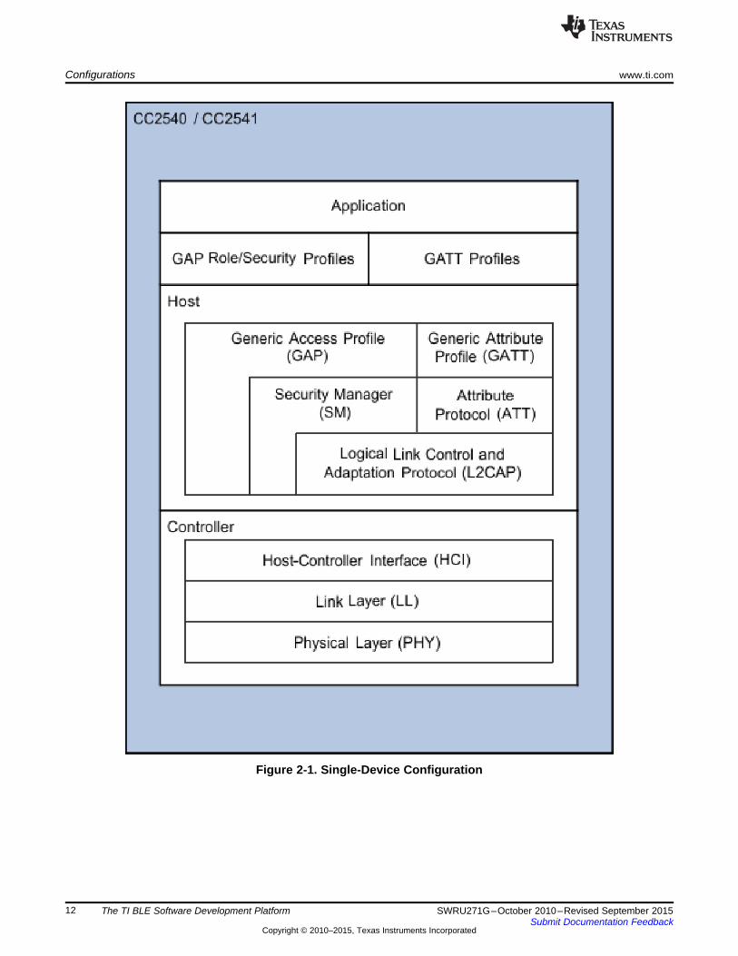
The BLE protocol stack (or protocol stack) consists of two sections: the controller and the host. Thisseparation of controller and host derives from standard Bluetooth BR/EDR devices, where the twosections were often implemented separately. Profiles and applications are implemented in Figure 1-2 ofthe generic access protocol (GAP) and generic attribute protocol (GATT) layers of the protocol stack.
The physical layer (PHY) is a 1-Mbps adaptive frequency-hopping Gaussian Frequency-Shift Keying(GFSK) radio operating in the unlicensed 2.4-GHz industrial, scientific, and medical (ISM) band.
The link layer (LL) controls the RF state of the device.
The device has five possible states:• standby• advertising• scanning• initiating• connected
9SWRU271G–October 2010–Revised September 2015 OverviewSubmit Documentation Feedback
Copyright © 2010–2015, Texas Instruments Incorporated

BLE Protocol Stack Basics www.ti.com
Advertisers transmit data without forming a BLE connection, while scanners receive the data broadcastedby advertisers. An initiator is a device that responds to an advertiser by requesting to connect. If theadvertiser accepts, both the advertiser and initiator connect. When a device is in a connected state, it iseither a master or slave. The device that initiated the connection becomes the master and the device thataccepted the request becomes the slave. This layer is implemented in the library code in the TI 1.4.1 BLEstack, .
The host control interface (HCI) layer provides a means of communication between the host and controllerthrough a standardized interface. This layer can be implemented either through a software API, or by ahardware interface such as UART, SPI, or USB. Device Information Service (Bluetooth Specification),Version 1.0 (24-May-2011) specifies the standard HCI commands and events. The TI BLE VendorSpecific HCI Reference Guide specifies the TI proprietary commands and events.
The link logical control and adaption protocol (L2CAP) layer provides data encapsulation services to theupper layers, allowing for logical, end-to-end communication of data. For more information on TI'simplementation of the L2CAP layer, see Section 5.5.
The security manager (SM) layer defines the methods for pairing and key distribution, and providesfunctions for the other layers of the protocol stack to securely connect with and exchange data withanother device. For more information on TI's implementation of the SM layer, see Section 5.3.
The GAP layer directly interfaces with the application and/or profiles to handle device discovery andconnection-related services for the device. GAP also handles the initiation of security features. For moreinformation on the GAP layer, see Section 5.1.
The attribute protocol (ATT) layer protocol lets a device expose certain pieces of data (attributes) toanother device.
The GATT layer is a service framework that defines the subprocedures for using ATT. GATTsubprocedures handle data communications between two devices in a BLE connection. The applicationand/or profiles use GATT directly. For more information on the ATT and GATT layers, see Section 5.4.
10 Overview SWRU271G–October 2010–Revised September 2015Submit Documentation Feedback
Copyright © 2010–2015, Texas Instruments Incorporated

Chapter 2SWRU271G–October 2010–Revised September 2015
The TI BLE Software Development Platform
The TI royalty-free, BLE software development kit is a complete software platform for developing single-mode BLE applications. The kit is based on the CC2540/41 complete System-on-Chip (SoC) solution. Thesolution combines a 2.4-GHz RF transceiver, microcontroller, up to 256KB of in-system programmablememory, 8KB of RAM, and a full range of peripherals.
2.1 ConfigurationsThe platform supports two different stack and application configurations:• Single-Device: The controller, host, profiles, and application are implemented on the CC2540/41 as a
true single-chip solution. This configuration is the simplest and most common when using theCC2540/41 devices. TI uses this configuration in most sample projects. The configuration is the mostcost effective and provides the lowest-power performance. The SimpleBLEPeripheral andSimpleBLECentral projects are examples of applications built using the single-device configuration. Formore information on these projects, see Chapter 3.
11SWRU271G–October 2010–Revised September 2015 The TI BLE Software Development PlatformSubmit Documentation Feedback
Copyright © 2010–2015, Texas Instruments Incorporated
Configurations www.ti.com
Figure 2-1. Single-Device Configuration
12 The TI BLE Software Development Platform SWRU271G–October 2010–Revised September 2015Submit Documentation Feedback
Copyright © 2010–2015, Texas Instruments Incorporated

www.ti.com Configurations
• Network Processor: The controller and host layers are implemented together on the CC2540/41, whilethe profiles and the application are implemented separately on an external host processor. Theapplication and profiles communicate with the CC2540/41 through vendor-specific HCI commandsusing an SPI, a UART interface, or a virtual UART interface over USB. This configuration is optimal forapplications that execute on another device such as an external microcontroller or a PC. When usingthis type of application, you can develop it externally while running the BLE stack on the CC2540/41.To use the network processor, you must use the HostTestRelease project.
Figure 2-2. Network Processor Configuration
13SWRU271G–October 2010–Revised September 2015 The TI BLE Software Development PlatformSubmit Documentation Feedback
Copyright © 2010–2015, Texas Instruments Incorporated

Projects www.ti.com
2.2 ProjectsThe SimpleBLEPeripheral project consists of sample code that demonstrates a simple application in thesingle-device configuration. You can use this project as a reference for developing a slave/peripheralapplication.
The SimpleBLECentral project is similar because it demonstrates a simple master/central application inthe single-device configuration, and can be a reference for developing master/central applications.
The HostTestRelease project is used to build the BLE network processor software for the CC2540/41.This project contains configurations for both master and slave roles.
The BLE development kit includes other sample projects. These projects implement various profiles anddemonstration applications. For more information on these other projects, see the TI CC2540 Bluetoothlow energy Sample Applications Guide.
2.3 Software OverviewSoftware developed using the BLE software development kit consists of following five major components:• OSAL• HAL• The BLE Protocol Stack• Profiles• Application
The kit provides the BLE protocol stack as object code and the OSAL and HAL components in sourceform.
The kit provides three GAP profiles:• Peripheral role• Central role• Peripheral bond manager
The kit also provides several sample GATT profiles and applications.
Path and file references in this document assume that you have installed the BLE development kitsoftware to the path: C:\Texas Instruments\BLE-CC254X-1.4.1\.
NOTE: This guide references the SimpleBLEPeripheral project. The BLE projects in thedevelopment kit follow a similar structure.
14 The TI BLE Software Development Platform SWRU271G–October 2010–Revised September 2015Submit Documentation Feedback
Copyright © 2010–2015, Texas Instruments Incorporated
Chapter 3SWRU271G–October 2010–Revised September 2015
The Operating System Abstraction Layer (OSAL)
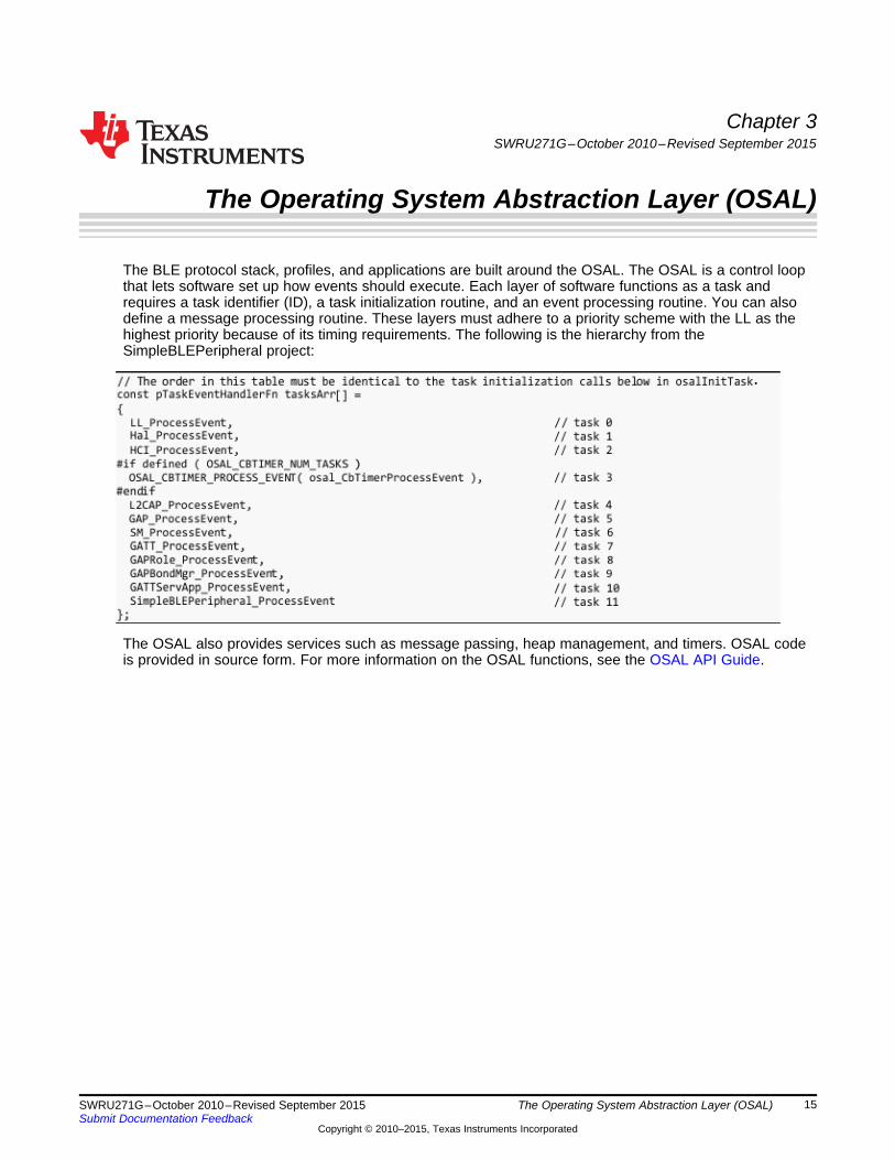
The BLE protocol stack, profiles, and applications are built around the OSAL. The OSAL is a control loopthat lets software set up how events should execute. Each layer of software functions as a task andrequires a task identifier (ID), a task initialization routine, and an event processing routine. You can alsodefine a message processing routine. These layers must adhere to a priority scheme with the LL as thehighest priority because of its timing requirements. The following is the hierarchy from theSimpleBLEPeripheral project:
The OSAL also provides services such as message passing, heap management, and timers. OSAL codeis provided in source form. For more information on the OSAL functions, see the OSAL API Guide.
15SWRU271G–October 2010–Revised September 2015 The Operating System Abstraction Layer (OSAL)Submit Documentation Feedback
Copyright © 2010–2015, Texas Instruments Incorporated

Task Initialization www.ti.com
3.1 Task InitializationTo use OSAL, locate a call to osal_start_system() at the end of the main() function. This function call isthe OSAL routine that starts the system. This routine starts the system and calls the osalInitTasks()function defined by the application. In the SimpleBLEPeripheral project, you can find this function inOSAL_SimpleBLEPeripheral.c:
Each layer of software using OSAL must have an initialization routine called from the functionosalInitTasks(). Within this function, the initialization routine for every layer of software is called within theosalInitTasks(). As each task initialization routine is called, an 8-bit task ID value is assigned to the task.
NOTE: When creating an application, add this 8-bit task ID value to the end of the list and ensurethat the task ID is greater than the other task ID values. OSAL and HAL components areprovided in source form.
The task ID determines the priority of the tasks. The task ID gives lower values higher priority. Theprotocol stack tasks must have the highest priority. The initialization function of the SimpleBLEPeripheralapplication, SimpleBLEPeripheral_Init(), has the highest task ID and the lowest priority.
16 The Operating System Abstraction Layer (OSAL) SWRU271G–October 2010–Revised September 2015Submit Documentation Feedback
Copyright © 2010–2015, Texas Instruments Incorporated

www.ti.com Task Events and Event Processing
3.2 Task Events and Event ProcessingAfter the OSAL initializes, it runs in an infinite loop checking for task events. You can find this loop in theosal_start_system() function in the OSAL.c file. Task events are stored as unique bits in a 16-bit variablewhere each bit corresponds to a unique event. The application determines the definition and use of theseevent flags. Figure 3-1 shows a flow diagram of the OSAL processing scheme.
Figure 3-1. OSAL Task Loop
If the SimpleBLEPeripheral application defines a flag in simpleBLEPeripheral.h:SBP_START_DEVICE_EVT (0x0001) indicating the initial device start is complete, the applicationprocessing begins. The application cannot define one reserved flag value (0x8000). This valuecorresponds to the event SYS_EVENT_MSG for messaging between tasks (see Section 3.4 for moreinformation).
When the OSAL detects an event set for a task, it calls the event processing routine of that task toprocess the event. The task layer must add its own event processing routine to the table formed by thearray of function pointers called tasksArr (defined in OSAL_SimpleBLEPeripheral.c for theSimpleBLEPeripheral example project). The order of the event processing routines in tasksArr is the sameas the order of task IDs in the osalInitTasks() function. Maintaining this task order is required for thecorrect software layer to process events.
17SWRU271G–October 2010–Revised September 2015 The Operating System Abstraction Layer (OSAL)Submit Documentation Feedback
Copyright © 2010–2015, Texas Instruments Incorporated
Heap Manager www.ti.com
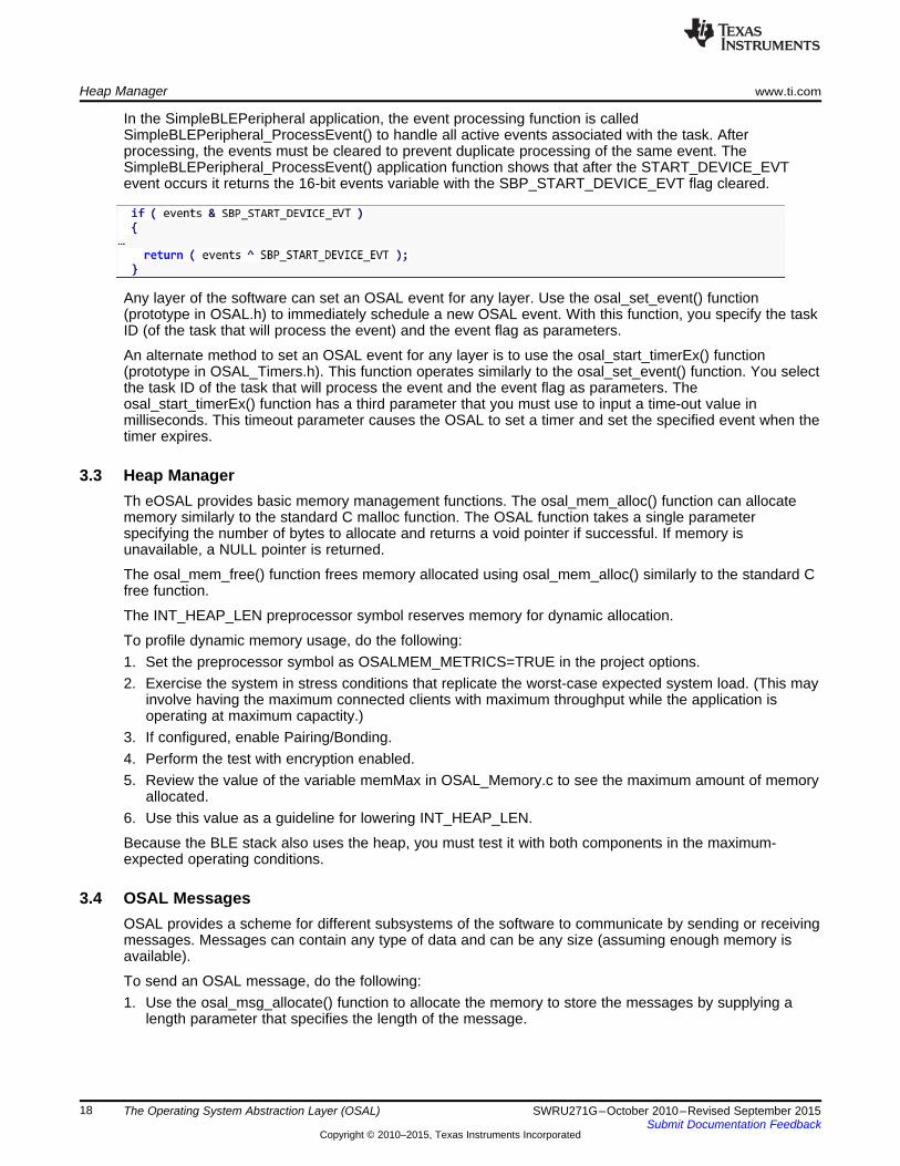
In the SimpleBLEPeripheral application, the event processing function is calledSimpleBLEPeripheral_ProcessEvent() to handle all active events associated with the task. Afterprocessing, the events must be cleared to prevent duplicate processing of the same event. TheSimpleBLEPeripheral_ProcessEvent() application function shows that after the START_DEVICE_EVTevent occurs it returns the 16-bit events variable with the SBP_START_DEVICE_EVT flag cleared.
Any layer of the software can set an OSAL event for any layer. Use the osal_set_event() function(prototype in OSAL.h) to immediately schedule a new OSAL event. With this function, you specify the taskID (of the task that will process the event) and the event flag as parameters.
An alternate method to set an OSAL event for any layer is to use the osal_start_timerEx() function(prototype in OSAL_Timers.h). This function operates similarly to the osal_set_event() function. You selectthe task ID of the task that will process the event and the event flag as parameters. Theosal_start_timerEx() function has a third parameter that you must use to input a time-out value inmilliseconds. This timeout parameter causes the OSAL to set a timer and set the specified event when thetimer expires.
3.3 Heap ManagerTh eOSAL provides basic memory management functions. The osal_mem_alloc() function can allocatememory similarly to the standard C malloc function. The OSAL function takes a single parameterspecifying the number of bytes to allocate and returns a void pointer if successful. If memory isunavailable, a NULL pointer is returned.
The osal_mem_free() function frees memory allocated using osal_mem_alloc() similarly to the standard Cfree function.
The INT_HEAP_LEN preprocessor symbol reserves memory for dynamic allocation.
To profile dynamic memory usage, do the following:1. Set the preprocessor symbol as OSALMEM_METRICS=TRUE in the project options.2. Exercise the system in stress conditions that replicate the worst-case expected system load. (This may
involve having the maximum connected clients with maximum throughput while the application isoperating at maximum capactity.)
3. If configured, enable Pairing/Bonding.4. Perform the test with encryption enabled.5. Review the value of the variable memMax in OSAL_Memory.c to see the maximum amount of memory
allocated.6. Use this value as a guideline for lowering INT_HEAP_LEN.
Because the BLE stack also uses the heap, you must test it with both components in the maximum-expected operating conditions.
3.4 OSAL MessagesOSAL provides a scheme for different subsystems of the software to communicate by sending or receivingmessages. Messages can contain any type of data and can be any size (assuming enough memory isavailable).
To send an OSAL message, do the following:1. Use the osal_msg_allocate() function to allocate the memory to store the messages by supplying a
length parameter that specifies the length of the message.
18 The Operating System Abstraction Layer (OSAL) SWRU271G–October 2010–Revised September 2015Submit Documentation Feedback
Copyright © 2010–2015, Texas Instruments Incorporated
www.ti.com OSAL Messages
NOTE: A pointer to a buffer containing the allocated space is returned (you do not need to useosal_mem_alloc() when using osal_msg_allocate()).
If no memory is available, a NULL pointer is returned.
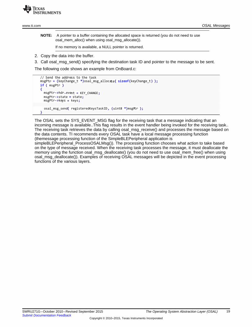
2. Copy the data into the buffer.3. Call osal_msg_send() specifying the destination task ID and pointer to the message to be sent.
The following code shows an example from OnBoard.c:
The OSAL sets the SYS_EVENT_MSG flag for the receiving task that a message indicating that anincoming message is available..This flag results in the event handler being invoked for the receiving task..The receiving task retrieves the data by calling osal_msg_receive() and processes the message based onthe data contents. TI recommends every OSAL task have a local message processing function(themessage processing function of the SimpleBLEPeripheral application issimpleBLEPeripheral_ProcessOSALMsg()). The processing function chooses what action to take basedon the type of message received. When the receiving task processes the message, it must deallocate thememory using the function osal_msg_deallocate() (you do not need to use osal_mem_free() when usingosal_msg_deallocate()). Examples of receiving OSAL messages will be depicted in the event processingfunctions of the various layers.
19SWRU271G–October 2010–Revised September 2015 The Operating System Abstraction Layer (OSAL)Submit Documentation Feedback
Copyright © 2010–2015, Texas Instruments Incorporated

Chapter 4SWRU271G–October 2010–Revised September 2015
The Application and Profiles
The BLE software development kit contains a sample project, SimpleBLEPeripheral, that implements abasic BLE peripheral device. This project is built using the single-device stack configuration, with thestack, profiles, and application running on the CC2540/41.
4.1 Project OverviewOn the left side of the IAR window, the Workspace section lists the files used by the project.
Figure 4-1. Project Files
20 The Application and Profiles SWRU271G–October 2010–Revised September 2015Submit Documentation Feedback
Copyright © 2010–2015, Texas Instruments Incorporated

www.ti.com Project Overview
The file list is divided into the following groups:• APP – These are the application source code and header files. More information on these files can be
found later in this section.• HAL – This group contains the HAL source code and header files. See Chapter 6 for more information
on the HAL group.• INCLUDE – This group includes all of the necessary header files for the BLE protocol stack API (see
appendices A through G and CC2540 Bluetooth low energy API Guide for details).• LIB – This group contains the protocol stack library file CC2540_BLE_peri.lib. For more information on
the protocol stack libraries, see Section 5.7.• NPI – Network processor interface, a transport layer that allows you to route HCI data to a serial
interface. CC254X_BLE_HCI_TL_Full.lib must be included for this capability (see the HostTest projectin the SDK). If not used, the CC254X_BLE_HCI_TL_None.lib should be used (seeSimpleBLEPeripheral in the SDK) when developing a single-chip application.
• OSAL – This group contains the OSAL source code and header files. See OSAL API Guide andChapter 3 for more information on the OSAL.
• PROFILES – This group contains the source code and header files for the GAP role profile, GAPsecurity profile, and the sample GATT profile. In addition, this section contains the necessary headerfiles for the GATT server application. See Chapter 5 for more information on these modules.
• TOOLS – This group contains the configuration files buildComponents.cfg and buildConfig.cfg.Section 5.7 describes these files and contains the files OnBoard.c and OnBoard.h, which handleinterface functions.
• OUTPUT – This group contains files that are generated by IAR during the build process, includingbinaries and the map file (see Section 8.2.4).
21SWRU271G–October 2010–Revised September 2015 The Application and ProfilesSubmit Documentation Feedback
Copyright © 2010–2015, Texas Instruments Incorporated

Start-up in main() www.ti.com
4.2 Start-up in main()The main() function in SimpleBLEPeripheral_Main.c is the starting point at runtime. This function brings upthe board and initializes the OSAL and SNV drivers. Next, this function initializes power management andcreates the tasks. Finally, the function calls the osal_start_system(), which starts the processing loop(OSAL) and does not return.
22 The Application and Profiles SWRU271G–October 2010–Revised September 2015Submit Documentation Feedback
Copyright © 2010–2015, Texas Instruments Incorporated

www.ti.com Application Initialization
4.3 Application InitializationThe initialization of the application occurs in two phases. OSAL calls the SimpleBLEPeripheral_Init()function. This function sets up the GAP role profile parameters, GAP characteristics, the GAP bondmanager parameters, and simpleGATTprofile parameters. This function also sets an OSALSBP_START_DEVICE_EVT event.
The processing in this event triggers the second phase of the initialization, which is in theSimpleBLEPeripheral_ProcessEvent() function. During this phase, the GAPRole_StartDevice() function iscalled to set up the GAP functions. This function sets up the GAP functions of the application.Connectable undirected advertisements make the device discoverable (for CC2540/41DK-MINI keyfobbuilds, the device becomes discoverable when you press the button on the right). A central device candiscover the peripheral device by scanning. If a central device sends a request to connect to theperipheral device, the peripheral device accepts the request and goes into a connected state as a slave. Ifthe peripheral device recieves no connection request, the device remains discoverable for 30.72 secondsbefore going into a standby state.
The project also includes the simpleGATTProfile service. A connected central device operating as a GATTclient can perform characteristic reads and writes on simpleGATTProfile characteristic values. The devicecan also enable notifications of one of the characteristics.
4.4 Event ProcessingAfter initialization, the application task processes events in SimpleBLEPeripheral_ProcessEvent when a bitis set in its events variable. Possible sources of events are described in the following subsections
4.4.1 Periodic EventThe application contains an OSAL event called SBP_PERIODIC_EVT. An OSAL timer setsSBP_PERIODIC_EVT to occur periodically. After the SBP_START_DEVICE_EVT processing hascompleted, the timer is set with a time-out value of PERIODIC_EVT_PERIOD (the default value is 5000milliseconds). Every 5 seconds the periodic event occurs and the function performPeriodicTask() is called.
The performPeriodicTask() function retrieves the value of the third characteristic in the simpleGATTProfileand copies that value into the fourth characteristic. This periodic event processing is an example fordemonstration only but highlights how a custom operation can be performed in a periodic task. Beforeprocessing the periodic event, a new OSAL timer is started, which sets up the next periodic task.
23SWRU271G–October 2010–Revised September 2015 The Application and ProfilesSubmit Documentation Feedback
Copyright © 2010–2015, Texas Instruments Incorporated

Event Processing www.ti.com
4.4.2 OSAL MessagesOSAL messages can come from various layers of the BLE stack. For example, these messages can befrom key presses sent by the HAL. The application has code specific to the Keyfob reference hardware inthe CC2540/41DK-MINI development kit. This code is surrounded by the preprocessor directive #if defined(CC2540_MINIDK) and gets compiled when using the CC2540/41DK-MINI Keyfob configuration. Thiscode adds the TI-proprietary simple keys service to the GATT server and handles key presses through thesimple keys profile.
Each time you press or release a key on the keyfob, HAL sends an OSAL message to the application. AsSection 3.4 describes, this action causes a SYS_EVENT_MSG event to occur. This event is handled inthe application by the function simpleBLEperipheral_ProcessOSALMsg(). In the currentSimpleBLEPeripheral application, the KEY_CHANGE message is the only recognized OSAL messagetype. You can define additional message types. The KEY_CHANGE message event processing calls thecalls the simpleBLEPeripheral_HandleKeys() function, which checks the state of the keys.
4.5 CallbacksOther than processing events, application code can also within the callback functions defined by theapplication such as simpleProfileChangeCB() and peripheralStateNotificationCB(). These callbacksprocess in the context of the task that called them. Processing should be limited in these callbacks. If anyintensive processing must be done, send an event from the callback to the application so that processingcan occur. For more information, see Section 4.4.
24 The Application and Profiles SWRU271G–October 2010–Revised September 2015Submit Documentation Feedback
Copyright © 2010–2015, Texas Instruments Incorporated

www.ti.com Complete Attribute Table
4.6 Complete Attribute TableSection 5.4.4.1 describes the process for adding profiles and services to the application. Figure 4-2 showsthe complete attributes of the SimpleBLEPeripheral and can be a reference when communicatingwirelessly with the device. Services are red. Characteristic descriptors are yellow. General attributes arewhite. See Section 5.4 for further details. When working with the SimpleBLEPeripheral application, printFigure 4-2 as a reference.
Figure 4-2. SimpleBLEPeripheral Complete Attribute Table
25SWRU271G–October 2010–Revised September 2015 The Application and ProfilesSubmit Documentation Feedback
Copyright © 2010–2015, Texas Instruments Incorporated

Additional Sample Projects www.ti.com
4.7 Additional Sample ProjectsThe BLE development kit includes several sample projects implementing profiles such as the following:• A heart rate monitor• A health thermometer• A proximity keyfob
See Chapter 5 for more information on these projects.
26 The Application and Profiles SWRU271G–October 2010–Revised September 2015Submit Documentation Feedback
Copyright © 2010–2015, Texas Instruments Incorporated

Chapter 5SWRU271G–October 2010–Revised September 2015
The BLE Protocol Stack
The BLE protocol stack is object code in the library files. TI does not provide the protocol stack sourcecode. TI intends the functionality of these layers to be understood as they interact directly with theapplication and profiles.
5.1 Generic Access Profile (GAP)
5.1.1 OverviewThe GAP layer of the BLE protocol stack defines the behavior of devices performing the following actions:• Device discovery• Link establishment• Link termination• Initiation of security features• Device configuration
See Figure 5-1 for an overview of possible device states.
Figure 5-1. GAP State Diagram
27SWRU271G–October 2010–Revised September 2015 The BLE Protocol StackSubmit Documentation Feedback
Copyright © 2010–2015, Texas Instruments Incorporated

Generic Access Profile (GAP) www.ti.com
The following describes the possible device states:• Standby: the initial idle state following reset or when the BLE stack is not active• Advertiser: The device advertises with specific data that signals it can connect to any initiating devices.
This advertisement contains the device address and additional data such as the device name.• Scanner: When receiving the advertisement, the scanning device sends a request to scan the
advertiser. The advertiser responds with a scan response. This process outlines how the devicediscovers other devices. The scanning device reads the advertising device and determines whether ornot they can connect.
• Initiator: When initiating, the initiator must specify a peer device address with which to connect. If theinitiator receives an advertisement that matches the address of the peer device, the initiator willrequest to establish a connection with the advertising device. The initiator specifies the initialconnection parameters when the connection is formed.
• Master or Slave: If the device was the advertiser , it becomes a slave after connecting. If the devicewas the initiator, it becomes a master after connecting.
5.1.1.1 Connection ParametersThis section describes the connection parameters sent by the initiating device with the connection request.These parameters can be modified by either device when the connection is established.
These parameters are the following:• Connection Interval – BLE connections use a frequency-hopping scheme. The devices send and
receive data on a specific channel at a specific time and meet at a new channel later. The link layer ofthe BLE protocol stack handles the channel switching. This meeting, where the two devices send andreceive data, is a connection event. If there is no application data sent or received, the devicesexchange link layer data to maintain the connection. The connection interval is the time between twoconnection events in units of 1.25 ms. The connection interval can range from a minimum value of 6(7.5 ms) to a maximum of 3200 (4.0 seconds).
Figure 5-2. Connection Event and Interval
Applications may require different connection intervals. This difference affects the power consumptionof the device. See the Measuring Power Consumption Application Note (SWRA347) for more detailedinformation on power consumption.
28 The BLE Protocol Stack SWRU271G–October 2010–Revised September 2015Submit Documentation Feedback
Copyright © 2010–2015, Texas Instruments Incorporated
www.ti.com Generic Access Profile (GAP)
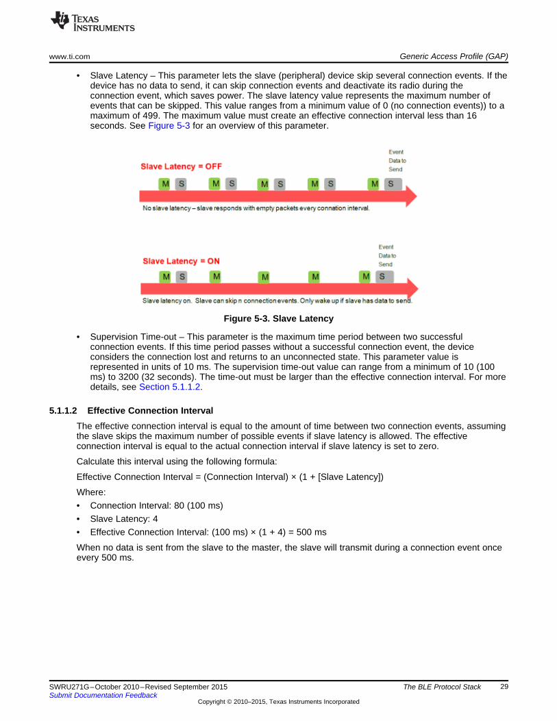
• Slave Latency – This parameter lets the slave (peripheral) device skip several connection events. If thedevice has no data to send, it can skip connection events and deactivate its radio during theconnection event, which saves power. The slave latency value represents the maximum number ofevents that can be skipped. This value ranges from a minimum value of 0 (no connection events)) to amaximum of 499. The maximum value must create an effective connection interval less than 16seconds. See Figure 5-3 for an overview of this parameter.
Figure 5-3. Slave Latency
• Supervision Time-out – This parameter is the maximum time period between two successfulconnection events. If this time period passes without a successful connection event, the deviceconsiders the connection lost and returns to an unconnected state. This parameter value isrepresented in units of 10 ms. The supervision time-out value can range from a minimum of 10 (100ms) to 3200 (32 seconds). The time-out must be larger than the effective connection interval. For moredetails, see Section 5.1.1.2.
5.1.1.2 Effective Connection IntervalThe effective connection interval is equal to the amount of time between two connection events, assumingthe slave skips the maximum number of possible events if slave latency is allowed. The effectiveconnection interval is equal to the actual connection interval if slave latency is set to zero.
Calculate this interval using the following formula:
Effective Connection Interval = (Connection Interval) × (1 + [Slave Latency])
Where:• Connection Interval: 80 (100 ms)• Slave Latency: 4• Effective Connection Interval: (100 ms) × (1 + 4) = 500 ms
When no data is sent from the slave to the master, the slave will transmit during a connection event onceevery 500 ms.
29SWRU271G–October 2010–Revised September 2015 The BLE Protocol StackSubmit Documentation Feedback
Copyright © 2010–2015, Texas Instruments Incorporated

Generic Access Profile (GAP) www.ti.com
5.1.1.3 Connection Parameter ConsiderationsIn many applications, the slave skips the maximum number of connection events. Consider the effectiveconnection interval when selecting or requesting connection parameters. Selecting the correct group ofconnection parameters helps optimize the power of the BLE device. The following list is a summary of thetrade-offs in connection-parameter settings:
Reducing the connection interval will do the following:• Increase the power consumed by both devices• Increase the throughput to and from both devices• Reduce the amount of time required to send data to and from both devices
Increasing the connection interval will do the following:• Reduce the power consumed by both devices• Reduce the throughput to and from both devices• Increase the amount of time required to send data to and from both devices
Reducing the slave latency or setting it to zero will do the following:• Increase the power consumed by the peripheral device• Reduce the amount of time required to send data from the central device to the peripheral device
Increasing the slave latency will do the following:• Reduce the power consumed by the peripheral device when it has no data to send to the central
device• Increase the amount of time required to send data from the central device to the peripheral device
5.1.1.4 Connection Parameter UpdateSometimes the central device will request a connection with a peripheral device containing connectionparameters unfavorable to the peripheral device. Other times, a peripheral device might changeparameters based on the peripheral application during a connection. The peripheral device can send aConnection Parameter Update Request to the central device to change the connection settings. ForBluetooth 4.0 devices, the L2CAP layer of the protocol stack handles this request.
This request contains the following four parameters:• A minimum connection interval• A maximum connection interval• A slave latency• A timeout
These values represent the parameters the peripheral device requires for the connection (the connectioninterval is given as a range). When the central device receives this request, it can accept or reject theparameters.
30 The BLE Protocol Stack SWRU271G–October 2010–Revised September 2015Submit Documentation Feedback
Copyright © 2010–2015, Texas Instruments Incorporated

www.ti.com Generic Access Profile (GAP)
5.1.1.5 Connection TerminationThe master or slave can terminate a connection for any reason. When either device initiates termination,the other must respond by acknowledging the termination indication before both devices disconnect.
5.1.2 GAP AbstractionThe application and profiles can call GAP API functions to perform BLE-related functions such asadvertising or connecting. Most of the GAP functionality is handled by the GAPRole Task. For moreinformation on this abstraction hierarchy, see Figure 5-4 .
Figure 5-4. GAP Abstraction
Configure the GAPRole module and use its APIs to interface with the GAP layer. Section 5.1.3 describesthe functions and parameters not handled or configured through the GAPRole task. These functions andparameters must be modified directly through the GAP layer.
5.1.3 Configuring the GAP LayerThe GAP layer functionality is defined mostly in library code. You can find the function headers in gap.h.Most of these functions are used by the GAPRole task and do not need to be called directly. Appendix Adefines the GAP API. You may want to modify several parameters before starting the GAPRole task.These parameters can be set or retrieved through the GAP_SetParamValue() and GAP_GetParamValue()functions. These parameters include advertising and scanning intervals, windows, and so forth (see B andC [GAPRole xxx API). A configuration of the GAP layer in SimpleBLEPeripheral_init() folows.
31SWRU271G–October 2010–Revised September 2015 The BLE Protocol StackSubmit Documentation Feedback
Copyright © 2010–2015, Texas Instruments Incorporated

GAPRole Task www.ti.com
5.2 GAPRole TaskAs in Section 3.1, the GAPRole task is a separate task (GAPRole_ProcessEvent) that simplifies theapplication by handling most of the GAP layer functionality. This task is enabled and configured by theapplication during initialization. Based on this configuration, many BLE protocol stack events are handleddirectly by the GAPRole task and never passed to the application. Callbacks exist that the application canregister with the GAPRole task. This registration notifies the GAPRole task of certain events. SeeSection B.3.1 for peripheral events or Section C.3.2 for central events.
Based on the configuration of the device, the GAP layer operates in one of the following four roles:• Broadcaster – an advertiser that is nonconnectable• Observer – scans for advertisements but cannot initiate connections• Peripheral – an advertiser that is connectable and operates as a slave in a single link-layer connection• Central – scans for advertisements and initiates connections and operates as a master in a single or
multiple link-layer connections (The BLE central protocol stack supports up to three simultaneousconnections.)
The BLE specification supports certain combinations of roles supported by the BLE protocol stack. Seethe for sample projects of combination roles. The CC254x does not support simultaneous peripheral andcentral device roles. This functionality is supported by the CC2640. The peripheral and central roles aredescribed in the following sections.
5.2.1 Peripheral RoleThe peripheral GAPRole task is defined in peripheral.c and peripheral.h. See Appendix B for descriptionsof the full API including commands, configurable parameters, events, and callbacks.
The general steps to use this module are the following:1. Initialize the GAPRole parameters (see Section B.2). Do this initialization in the application initialization
function (that is, SimpleBLEPeripheral_init()).
32 The BLE Protocol Stack SWRU271G–October 2010–Revised September 2015Submit Documentation Feedback
Copyright © 2010–2015, Texas Instruments Incorporated

www.ti.com GAPRole Task
2. Initialize the GAPRole task. Do this initialization when processing START_DEVICE_EVT. Thisinitialization involves passing function pointers to application callback functions. Section B.3 definesthese callbacks.
3. Send GAPRole commands from the application. The following is an example of the application usingGAPRole_TerminateConnection().
NOTE: The return value from the BLE protocol stack only indicates whether the attempt to terminatethe connection was initiated successfully. The termination of connection event sent to theapplication asynchronously and is described in the following example. The API in Section B.3lists the return parameters for each command and associated callback function events.
33SWRU271G–October 2010–Revised September 2015 The BLE Protocol StackSubmit Documentation Feedback
Copyright © 2010–2015, Texas Instruments Incorporated

GAPRole Task www.ti.com
4. The GAPRole task processes most of the GAP-related events passed to it from the BLE protocolstack. The task forwards some events to the application. The following is an example tracing theGAP_LINK_TERMINATED_EVENT from the BLE protocol stack to the application.
34 The BLE Protocol Stack SWRU271G–October 2010–Revised September 2015Submit Documentation Feedback
Copyright © 2010–2015, Texas Instruments Incorporated

www.ti.com GAPRole Task
5.2.2 Central RoleThe central GAPRole task is defined in central.c and central.h. For the full API including commands,configurable parameters, events, and callbacks, see Appendix C.
To use this module, do the following:1. Initialize the GAPRole parameters. Section B.2 defines these parameters. Define the parameters in the
application initialization function (that is, SimpleBLECentral_init()).
2. Initialize the GAPRole task. Do this initialization when processing START DEVICE EVT. Thisinitialization involves passing function pointers to application callback functions. Section C.3 definesthese callbacks.
3. Send GAPRole commands from the application. The following is an example of the application usingGAPCentralRole_StartDiscovery().
NOTE: The return value from the BLE protocol stack only indicates whether the attempt to performdevice discovery was initiated or not. The termination of connection event is returnedasynchronously and is described in the following step. See appendices A through G for thelist of return parameter associated with each API.
35SWRU271G–October 2010–Revised September 2015 The BLE Protocol StackSubmit Documentation Feedback
Copyright © 2010–2015, Texas Instruments Incorporated

GAPRole Task www.ti.com
4. The GAPRole task processes some of the GAP-related events passed to it from the BLE protocolstack. The task forwards some events to the application. The following is an example tracing theGAP_DEVICE_DISCOVERY_EVENT from the BLE protocol stack to the application.
36 The BLE Protocol Stack SWRU271G–October 2010–Revised September 2015Submit Documentation Feedback
Copyright © 2010–2015, Texas Instruments Incorporated

www.ti.com Gap Bond Manager (GAPBondMgr)
5.3 Gap Bond Manager (GAPBondMgr)The GAPBondMgr profile handles the initiation of security features during a BLE connection. Some datamay be readable or writeable only in an authenticated connection. Table 5-1 defines the terminology usedin BLE security.
Table 5-1. GAP Bond Manager Security Terms
Term DescriptionPairing The process of exchanging keysEncryption Data is encrypted after pairing, or re-encryption (a subsequent
connection where keys are looked up from nonvolatile memory)Authentication The pairing process completed with MITM (Man in the Middle)
protection (passcode, NFC, and so forth).Bonding Storing the encryption keys in nonvolatile memory to use for the
next encryption sequence.Authorization An additional application level key exchange in addition to
authenticationOOB Out of Band. Keys are not exchanged wirelessly, but rather over
some other source such as serial port or NFC. This alsoprovides MITM protection.
MITM Man in the Middle Protection. This prevents an attacker fromlistening to the keys transferred wirelessly to break theencryption.
Just Works Pairing method where keys are transferred wirelessly withoutMITM.
The general process to establish security is:1. Pair the keys (exchanging keys through the following methods).
(a) Just Works (to send the keys wirelessly)(b) MITM (to use a passcode to create a key)
2. Encrypt the link with keys from step 1.3. Bond the keys (store keys in secure flash [SNV]).4. When reconnected, use the keys stored in SNV to encrypt the link.
NOTE: You can skip steps. For example, you can to skip bonding and just re-pair afterreconnecting. The GAPBondMgr uses the SNV flash area to store bond information. Formore information on SNV, see Section 6.9
5.3.1 Overview of BLE SecurityThis section describes BLE security methods. For more information, see Device Information Service(Bluetooth Specification), Version 1.0 (24-May-2011).
When connected, the devices can go through a process called pairing. When paired, keys are establishedthat encrypt and can authenticate the link. Either device may require a passkey to complete the pairingprocess. This process is called man in the middle (MITM) protection. You could create this passcode witha value such as 000000. Alternatively, the passcode can be a predetermined randomly-generated valuedisplayed on the device. After the correct passkey is displayed and entered, the devices exchangesecurity keys to encrypt and authenticate the link. The input and output capabilities of the devices in thepairing request must match to make authentication is possible.
In many cases, the same central and peripheral devices often connect and disconnect from each other.BLE has a security feature that lets the devices exchange a long-term set of security keys when pairing.With this long-term set of security keys, re-pairing is unnecessary when reconnecting in the future. Thisfeature is called bonding and it lets the devices store the security keys and quickly reestablish encryptionand authentication after reconnecting without going through the pairing process.
37SWRU271G–October 2010–Revised September 2015 The BLE Protocol StackSubmit Documentation Feedback
Copyright © 2010–2015, Texas Instruments Incorporated

Gap Bond Manager (GAPBondMgr) www.ti.com
5.3.2 Using the GapBondMgr ProfileThe GAPBondMgr implements most of the functions in the overview. This section describes what theapplication must do to configure, start, and use the GAPBondMgr. The GAPRole also handles some of thefunctionality of the GAPBondMgr. The GAPBondMgr is defined in gapbondmgr.c. gapbondmgr.h.describes the API including commands, configurable parameters, events, and callbacks. The steps to usethis module are as follows. The SimpleBLECentral project is the example because it uses the callbackfunctions from the GAPBondMgr.1. Initialize the GAPBondMgr parameters. Do this in the application initialization function (that is,
SimpleBLECentral_init()). Consider the following parameters. For the example, the pairMode has beenchanged to initiate pairing.
2. Register application callbacks with the GAPBondMgr. Do this registration after the GAPRole starts inthe START_DEVICE_EVT processing:
The GAPBondMgr is configured and operates autonomously. When a connection is established, theGAPBondMgr initiates pairing and bonding depending on the configuration parameters from Step 1.You can set a few parameters asynchronously such as GAPBOND_ERASE_ALLBONDS. Allcommunication between the GAPBondMgr and the application occurs through the callbacks that wereregistered in Step 2. The following is a flow diagram example from SimpleBLECentral of theGAPBondMgr, notifying the application that pairing has started. The following sections expand onthese callbacks.
38 The BLE Protocol Stack SWRU271G–October 2010–Revised September 2015Submit Documentation Feedback
Copyright © 2010–2015, Texas Instruments Incorporated

www.ti.com Gap Bond Manager (GAPBondMgr)
39SWRU271G–October 2010–Revised September 2015 The BLE Protocol StackSubmit Documentation Feedback
Copyright © 2010–2015, Texas Instruments Incorporated

Gap Bond Manager (GAPBondMgr) www.ti.com
5.3.3 GAPBondMgr Examples for Various Security ModesThis section provides message diagrams for the types of security to implement. These security typesassume acceptable input and output capabilities are present for the security mode. See the Specificationof the Bluetooth System, Covered Core Package version: 4.0 (30-June-2010) on how input and outputcapabilities affect pairing.
5.3.3.1 Pairing Disabled
With pairing set to FALSE, the protocol stack rejects any attempt to pair.
5.3.3.2 Just Works Pairing Without BondingJust Works pairing encrypts without MITM authentication and is vulnerable to MITM attacks. For JustWorks pairing without bonding, configure the GAPBondMgr as follows:
For an overview of this process for peripheral device, see Figure 5-5.
Figure 5-5. Just Works Pairing
40 The BLE Protocol Stack SWRU271G–October 2010–Revised September 2015Submit Documentation Feedback
Copyright © 2010–2015, Texas Instruments Incorporated

www.ti.com Gap Bond Manager (GAPBondMgr)
The GAPBondMgr pairing states are passed to the application callback when required during the pairingprocess. GAPBOND_PAIRING_STATE_STARTED is passed when sent or received by the stack.GAPBOND_PAIRING_STATE_COMPLETE is sent when the pairing completes. A Just Works pairingrequires the pair-state callback. For more information, see Section F.3.
41SWRU271G–October 2010–Revised September 2015 The BLE Protocol StackSubmit Documentation Feedback
Copyright © 2010–2015, Texas Instruments Incorporated

Gap Bond Manager (GAPBondMgr) www.ti.com
5.3.3.3 Just Works Pairing With Bonding EnabledTo enable bonding with a Just Works pairing, use the following settings:
For an overview of this process for peripheral device, see Figure 5-6.
Figure 5-6. Bonding After Just Works Pairing
42 The BLE Protocol Stack SWRU271G–October 2010–Revised September 2015Submit Documentation Feedback
Copyright © 2010–2015, Texas Instruments Incorporated

www.ti.com Gap Bond Manager (GAPBondMgr)
NOTE: GAPBOND_PAIRING_STATE_COMPLETE is only passed to the application pair statecallback after the initial connection, pairing, and bond. For future connections, the securitykeys loads from flash. This capability skips the pairing process. In this case, onlyPAIRING_STATE_BONDED is passed to the application pair state callback.
5.3.3.4 Authenticated PairingAuthenticated pairing requires MITM protection. This method is a way of transferring a passcode betweenthe devices. The passcode cannot transmit wirelessly and is displayed on one device (typically on an LCDscreen or a serial number on the device) and entered on the other device.
To pair with MITM authentication, use the following settings:
This method requires an additional step in the security process in Figure 5-7. After pairing is started, theGAPBondMgr notifies the application that a passcode is required through a passcode callback. Dependingon the input and output capabilities of the device, the device must display and/or enter the passcode. Ifentering a passcode, the application sends this passcode to the GAPBondMgr.
Figure 5-7. Pairing With MITM Authentication
43SWRU271G–October 2010–Revised September 2015 The BLE Protocol StackSubmit Documentation Feedback
Copyright © 2010–2015, Texas Instruments Incorporated

Gap Bond Manager (GAPBondMgr) www.ti.com
This passcode communication with the GAPBondMgr uses a passcode callback function when registeringwith GAPBondMgr. You must add a passcode function to the GAPBondMgr application callbacks. Thefollowing is an example of a passcode function.
When the GAPBondMgr requires a passcode, the GAPBondMgr use the following callback to request apasscode from the application. Depending on the input and output capabilities of the devices, the callbackfunction should either display a passcode or read in an entered passcode. This passcode must be sent bythe application to the GAPBondMgr using the GAPBondMgr_PasscodeRsp() function. The following is anexample of the SimpleBLECentral.
In the previous example, a random password is generated and displayed on an LCD screen by thepasscode callback function. The other connected device must then enter this passcode.
5.3.3.5 Authenticated Pairing with Bonding EnabledAfter pairing and encrypting with MITM authentication, bonding occurs similarly as described inSection 5.3.3.3.
44 The BLE Protocol Stack SWRU271G–October 2010–Revised September 2015Submit Documentation Feedback
Copyright © 2010–2015, Texas Instruments Incorporated

www.ti.com Generic Attribute Profile (GATT)
5.4 Generic Attribute Profile (GATT)TI designed the GATT layer of the BLE protocol stack for use by the application for data communicationbetween two connected devices. Data are passed and stored in the form of characteristics, which arestored in memory on the BLE device. In GATT when two devices are connected, they each fill one of tworoles:• GATT Server — This device contains the characteristic database being read or written by a GATT
client.• GATT Client — This device reads or writes data from or to the GATT server. The Figure 5-8 shows this
relationship in a sample BLE connection where the peripheral device (a SensorTag) is the GATTserver and the central device (a smart phone) is the GATT client.
Figure 5-8. GATT Client and Server
Typically, the GATT roles of client and server are independent from the GAP roles of peripheral andcentral. A peripheral can be either a GATT client or server and a central device can be either a GATTclient or server. A device can also act as both a GATT client and a GATT server.
5.4.1 GATT Characteristics and AttributesWhile characteristics are sometimes interchangeable when referring to BLE, consider them as groups ofinformation called attributes. Attributes are the base groups of information transferred between devices.Characteristics organize and use attributes as data values, properties, and configuration information.
A typical characteristic is composed of the following attributes:• Characteristic Value: This value is the data value of the characteristic.• Characteristic Declaration: A descriptor stores the properties, location, and type of the characteristic
value.• Client Characteristic Configuration: This configuration lets the GATT server configure the characteristic
to be sent to the GATT server (notified) or sent to the GATT server and expect an acknowledgment(indicated).
• Characteristic User Description: This description is an ASCII string describing the characteristic.
These attributes are stored in the GATT server in an attribute table. The following properties areassociated with each attribute:• Handle – This property is the attribute’s index in the table. Every attribute has a unique handle.• Type – This attribute indicates what the attribute data represents. This attribute is called a universal
unique identifier (UUID). Some of these UUIDs are defined by Bluetooth SIG and others are user-definable.
• Permissions – This attribute enforces whether and how a GATT client device can access the value of
45SWRU271G–October 2010–Revised September 2015 The BLE Protocol StackSubmit Documentation Feedback
Copyright © 2010–2015, Texas Instruments Incorporated

Generic Attribute Profile (GATT) www.ti.com
the attribute.
46 The BLE Protocol Stack SWRU271G–October 2010–Revised September 2015Submit Documentation Feedback
Copyright © 2010–2015, Texas Instruments Incorporated

www.ti.com Generic Attribute Profile (GATT)
5.4.2 GATT Services and ProfileA GATT service is a collection of characteristics. For example, the heart rate service contains a heart ratemeasurement characteristic and a body location characteristic. You can group services together to form aprofile. Many profiles implement only one service; so the two terms are used interchangeably.
The SimpleBLEPeripheral application has the following four GATT profiles:• Mandatory GAP Service – This service contains device and access information such as the device
name, vendor identification, and product identification. This service is a part of the BLE protocol stackand is required for every BLE device per the BLE specification. The source code for this service is notprovided but is built into the stack library.
• Mandatory GATT Service – This service contains information about the GATT server and is a part ofthe BLE protocol stack. This service is required for every GATT server device per the BLEspecification. The source code for this service is not provided but is built into the stack library.
• Device Information Service – This service exposes information about the device such as the hardwareversion, software version, firmware version, regulatory information, compliance information, and thename of the manufacturer. The Device Information Service is part of the BLE protocol stack and isconfigured by the application. See Device Information Service (Bluetooth Specification), version 1.0(24-May-2011) for more information.
• simpleGATTProfile Service – This service is a sample profile for testing and demonstration. The fullsource code is in the files simpleGATTProfile.c and simpleGATTProfile.h.
Figure 5-9 shows and describes the portion of the attribute table in the SimpleBLEPeripheral projectcorresponding to the simpleGATTProfile service. This section is an introduction to the attribute table. SeeSection 5.4.4.2 for information on how this profile is implemented in the code.
Figure 5-9. simpleGATTProfile Characteristic Table from BTool
47SWRU271G–October 2010–Revised September 2015 The BLE Protocol StackSubmit Documentation Feedback
Copyright © 2010–2015, Texas Instruments Incorporated

Generic Attribute Profile (GATT) www.ti.com
The simpleGATTProfile contains the following five characteristics:• SIMPLEPROFILE_CHAR1 – A 1-byte value that can be read or written from a GATT-client device• SIMPLEPROFILE_CHAR2 – A 1-byte value that can be read from a GATT-client device, but cannot be
written.• SIMPLEPROFILE_CHAR3 – A 1-byte value that can be written from a GATT-client device, but cannot
be read.• SIMPLEPROFILE_CHAR4 – A 1-byte value that cannot be directly read or written from a GATT-client
device (This value is notifiable and can be configured for notifications to be sent to a GATT clientdevice.)
• SIMPLEPROFILE_CHAR5 – A 5-byte value that can be read but not written from a GATT-client device
The following is a line-by-line description of this attribute table, referenced by the attribute handle:• 0x001F: This attribute is the simpleGATTprofile service declaration. This declaration has a UUID of
0x2800 (Bluetooth-defined GATT_PRIMARY_SERVICE_UUID). The value of this declaration is theUUID of the simpleGATTprofile (custom-defined by TI).
• 0x0020: This attribute is the SIMPLEPROFILE_CHAR1 characteristic declaration. This declaration canbe thought of as a pointer to the value of SIMPLEPROFILE_CHAR1. This declaration has a UUID of0x2803 (Bluetooth-defined GATT_CHARACTER_UUID). The value of this declaration and all othercharacteristic declarations is a five-byte value explained as follows (from MSB to LSB):– Byte 0: the properties of the SIMPLEPROFILE_CHAR1. These properties are defined in
Specification of the Bluetooth System, Covered Core Package version: 4.0 (30-June-2010). Thefollowing are a few of the relevant properties:• 0x02: Permits reads of the characteristic value• 0x04: Permits writes of the characteristic value without a response• 0x08: Permits writes of the characteristic value (with a response)• 0x10: Permits of notifications of the characteristic value (without acknowledgement)• 0x20: Permits notifications of the characteristic value (with acknowledgement)The value of 0x0A means the characteristic is readable (0x02) and writeable (0x08).
– Bytes 1-2: the byte-reversed handle where the SIMPLEPROFILE_CHAR1 value is located (handle0x0021)
– Bytes 3-4: the UUID of the SimpleProfileChar1 value (custom-defined 0xFFF1)• 0x0021: This attribute is the SIMPLEPROFILE_CHAR1 value. The attribute has a UUID of 0xFFF1
(custom-defined). Its value is the actual payload data of the characteristic. Indicated by itscharacteristic declaration (handle 0x0020), this value is readable and writeable.
• 0x0022: This attribute is the SIMPLEPROFILE_CHAR1 user description. The attribute has a UUID of0x2901 (Bluetooth-defined). Its value is a user-readable string describing the characteristic.
• 0x0023 – 0x002F: These attributes follow the same structure as the SIMPLEPROFILE_CHAR1 withregard to the remaining four characteristics. The only different attribute, handle 0x002B, is described inthe following bullet.
• 0x002B: This attribute is the SIMPLEPROFILE_CHAR4 client characteristic configuration. Thisconfiguration has a UUID of 0x2902 (Bluetooth-defined). By writing to this attribute, a GATT server canconfigure the SIMPLEPROFILE_CHAR4 for notifications (writing 0x0001) or indications (writing0x0002). Writing a 0x0000 to this attribute will disable notifications and indications.
48 The BLE Protocol Stack SWRU271G–October 2010–Revised September 2015Submit Documentation Feedback
Copyright © 2010–2015, Texas Instruments Incorporated

www.ti.com Generic Attribute Profile (GATT)
5.4.3 GATT Client AbstractionLike the GAP layer, the GATT layer is also abstracted. This abstraction depend on whether the device is aGATT Client or a GATT server. According to Device Information Service (Bluetooth Specification), version1.0 (24-May-2011), the GATT layer is an abstraction of the ATT layer.
GATT clients do not have attribute tables or profiles because they gather information rather than serving it.Most interfacing with the GATT layer occurs directly from the application. Use the direct GATT APIdescribed in Appendix D. Figure 5-10 shows the abstraction.
Figure 5-10. GATT Client Abstraction
5.4.3.1 Using the GATT Layer DirectlyThis section describes how to use the GATT layer directly in the application. The functionality of the GATTlayer is implemented in the library code but you can find the header functions can in gatt.h. You can findthe complete API for the GATT layer in Appendix D. You can find more information on the functionality ofthese commands in the Device Information Service (Bluetooth Specification), version 1.0 (24-May-2011).GATT client applications uses these functions primarily. A few server-specific functions exist which aredescribed in the API and not considered here. Most GATT functions return ATT events to the application,so consider the ATT API in Appendix D. Perform the following procedure to use the GATT layer whenfunctioning as a GATT client (that is, in the SimpleBLECentral project):1. Initialize the GATT client. Do this in the application initialization function.
2. Register to receive incoming ATT indications and notifications. Do this in the application initializationfunction.
49SWRU271G–October 2010–Revised September 2015 The BLE Protocol StackSubmit Documentation Feedback
Copyright © 2010–2015, Texas Instruments Incorporated

Generic Attribute Profile (GATT) www.ti.com
3. Perform a GATT client procedure. The following example uses GATT_WriteCharValue(), which istriggered by pressing the key on the left in the SimpleBLECentral application.
50 The BLE Protocol Stack SWRU271G–October 2010–Revised September 2015Submit Documentation Feedback
Copyright © 2010–2015, Texas Instruments Incorporated

www.ti.com Generic Attribute Profile (GATT)
4. Receive and handle the response to the GATT client procedure in the application. In the followingexample, the application receives an ATT_WRITE_RSP event. See Section D.5 for a list of GATTcommands and their corresponding ATT events.
NOTE: Though the event sent to the application is an ATT event, it is sent as a GATT protocol stackmessage (GATT_MSG_EVENT).
Besides receiving responses to its own commands, a GATT client may also receiveasynchronous data from the GATT server as indications or notifications.
51SWRU271G–October 2010–Revised September 2015 The BLE Protocol StackSubmit Documentation Feedback
Copyright © 2010–2015, Texas Instruments Incorporated

Generic Attribute Profile (GATT) www.ti.com
5. Ensure the GATT client is registered to receive these ATT events in step 2.These events will also be sent as ATT events in GATT messages to the application and should behandled as described in this procedure.
5.4.4 GATT Server AbstractionAs a GATT server, most of the GATT functionality is handled by the individual GATT profiles. Theseprofiles use of the GattServApp, a configurable module which stores and manages the attribute table.Figure 5-11 shows the abstraction hierarchy:
Figure 5-11. GATT Server Abstraction
The design process is as follows:1. Create GATT profiles that configure the GATTServApp module.2. Use API of the module to interface with the GATT layer.
With a GATT server, direct calls to GATT layer functions are unnecessary. The application interfaces withthe profiles.
5.4.4.1 GATTServApp ModuleThe GATTServApp module stores and manages the application-wide attribute table. Various profiles usethe table to add their characteristics to the attribute table. The BLE stack uses the table to respond todiscovery requests from a GATT client. For example, a GATT client may send a Discover all PrimaryCharacteristics message. The BLE stack on the GATT server receives this message and uses theGATTServApp module to find and send the primary characteristics in the attribute table wirelessly. Thistype of functionality is beyond the scope of this document and is implemented in the library code. Thefunctions of the GATTServApp are accessible from the profiles and defined in gattservapp_util.c and in theAPI in Appendix E. These functions include finding specific attributes, reading client characteristicconfigurations, and modifying client characteristic configurations.
52 The BLE Protocol Stack SWRU271G–October 2010–Revised September 2015Submit Documentation Feedback
Copyright © 2010–2015, Texas Instruments Incorporated

www.ti.com Generic Attribute Profile (GATT)
5.4.4.1.1 Building Up the Attribute TableWhen powering on or resetting the device, the application builds the GATT table by using theGATTServApp module to add services. Each service is a list of attributes with UUIDs, values,permissions, and read/write call-backs. Figure 5-12 shows that this information is passed through theGATTServApp to GATT and stored in the stack. Do this in the application initialization function, that is,simpleBLEPeripheral_init():
Figure 5-12. Attribute Table Initialization
5.4.4.2 Profile ArchitectureThis section describes the architecture for profiles and provides functional examples of thesimpleGATTProfile in the SimpleBLEPeripheral project. See Section 5.4.2 for an overview of thesimpleGATTProfile.
To interface with the application and BLE protocol stack, each profile must contain the elements in thefollowing sections
53SWRU271G–October 2010–Revised September 2015 The BLE Protocol StackSubmit Documentation Feedback
Copyright © 2010–2015, Texas Instruments Incorporated
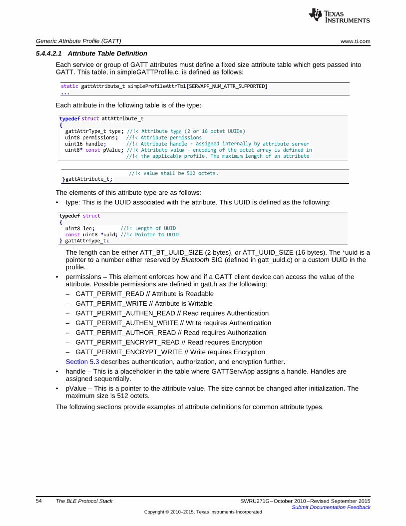
Generic Attribute Profile (GATT) www.ti.com
5.4.4.2.1 Attribute Table DefinitionEach service or group of GATT attributes must define a fixed size attribute table which gets passed intoGATT. This table, in simpleGATTProfile.c, is defined as follows:
Each attribute in the following table is of the type:
The elements of this attribute type are as follows:• type: This is the UUID associated with the attribute. This UUID is defined as the following:
The length can be either ATT_BT_UUID_SIZE (2 bytes), or ATT_UUID_SIZE (16 bytes). The *uuid is apointer to a number either reserved by Bluetooth SIG (defined in gatt_uuid.c) or a custom UUID in theprofile.
• permissions – This element enforces how and if a GATT client device can access the value of theattribute. Possible permissions are defined in gatt.h as the following:– GATT_PERMIT_READ // Attribute is Readable– GATT_PERMIT_WRITE // Attribute is Writable– GATT_PERMIT_AUTHEN_READ // Read requires Authentication– GATT_PERMIT_AUTHEN_WRITE // Write requires Authentication– GATT_PERMIT_AUTHOR_READ // Read requires Authorization– GATT_PERMIT_ENCRYPT_READ // Read requires Encryption– GATT_PERMIT_ENCRYPT_WRITE // Write requires EncryptionSection 5.3 describes authentication, authorization, and encryption further.
• handle – This is a placeholder in the table where GATTServApp assigns a handle. Handles areassigned sequentially.
• pValue – This is a pointer to the attribute value. The size cannot be changed after initialization. Themaximum size is 512 octets.
The following sections provide examples of attribute definitions for common attribute types.
54 The BLE Protocol Stack SWRU271G–October 2010–Revised September 2015Submit Documentation Feedback
Copyright © 2010–2015, Texas Instruments Incorporated
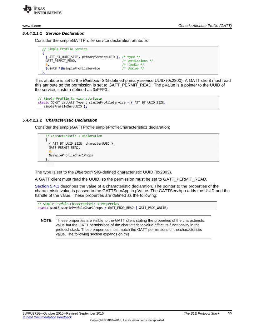
www.ti.com Generic Attribute Profile (GATT)
5.4.4.2.1.1 Service DeclarationConsider the simpleGATTProfile service declaration attribute:
This attribute is set to the Bluetooth SIG-defined primary service UUID (0x2800). A GATT client must readthis attribute so the permission is set to GATT_PERMIT_READ. The pValue is a pointer to the UUID ofthe service, custom-defined as 0xFFF0:
5.4.4.2.1.2 Characteristic DeclarationConsider the simpleGATTProfile simpleProfileCharacteristic1 declaration:
The type is set to the Bluetooth SIG-defined characteristic UUID (0x2803).
A GATT client must read the UUID, so the permission must be set to GATT_PERMIT_READ.
Section 5.4.1 describes the value of a characteristic declaration. The pointer to the properties of thecharacteristic value is passed to the GATTServApp in pValue. The GATTServApp adds the UUID and thehandle of the value. These properties are defined as the following:
NOTE: These properties are visible to the GATT client stating the properties of the characteristicvalue but the GATT permissions of the characteristic value affect its functionality in theprotocol stack. These properties must match the GATT permissions of the characteristicvalue. The following section expands on this.
55SWRU271G–October 2010–Revised September 2015 The BLE Protocol StackSubmit Documentation Feedback
Copyright © 2010–2015, Texas Instruments Incorporated

Generic Attribute Profile (GATT) www.ti.com
5.4.4.2.1.3 Characteristic ValueConsider the value of the simpleGATTProfile SIMPLEPROFILE_CHAR1.
The type is set to the custom-defined simpleProfileChar1 UUID (0xFFF1).
Because the properties of this characteristic value are readable and writeable, set the GATT permissionsto readable and writable.
NOTE: If the GATT permissions are not set to readable and writable, errors occur.
The pValue is a pointer to the location of the actual value. This value is statically defined in the profile asfollows:
5.4.4.2.1.4 Client Characteristic ConfigurationConsider the simpleGATTProfile simpleProfileCharacteristic4 configuration.
The type is set to the Bluetooth SIG-defined client characteristic configuration UUID (0x2902).
GATT clients must read and write to this so the GATT permissions are set to readable and writable.
The pValue is a pointer to the location of the client characteristic configuration array, defined in the profileas the following:
NOTE: Because this value must be cached for each connection, this is an array ion.Tthe followingsection describes this ion.
56 The BLE Protocol Stack SWRU271G–October 2010–Revised September 2015Submit Documentation Feedback
Copyright © 2010–2015, Texas Instruments Incorporated

www.ti.com Generic Attribute Profile (GATT)
5.4.4.2.2 Add Service FunctionAs Section 5.4.4.1 describes, when an application starts up it must add the GATT services it supports.Each profile needs a global AddService function that can be called by the application. Some of theseservices are defined in the protocol stack, such as GGS_AddService and GATTServApp_AddService.User-defined services must expose their own AddService function that the application can call for profileinitialization. Using SimpleProfile_AddService() as an example, these functions should do the following:• Allocate space for the client characteristic configuration (CCC) arrays.
As described in Section 5.4.4.2.1.4, a pointer to one of these arrays initialized in the profile. In theAddService function, several supported connections are declared and memory is allocated for eacharray. One CCC is defined in the simpleGATTProfile but the profile may contain additional CCCs.
• Initialize the CCC arrays.CCC values do not change between power downs and bonded device connections because they arestored in NV. For each CCC in the profile, the GATTServApp_InitCharCfg() function must be called.This function initializes the CCCs with information from a previously bonded connection. If the functioncannot find the information, set the initial values to default values.
• Register the profile with the GATTServApp.This function passes the attribute table of the profile to the GATTServApp so the attributes of theprofile are added to the application-wide attribute table, which is managed by the protocol stack. TheGATTServApp function assigns handles for each attribute. This function also passes pointers thecallback of the profile to the stack to initiate communication between the GATTServApp and the profile.
57SWRU271G–October 2010–Revised September 2015 The BLE Protocol StackSubmit Documentation Feedback
Copyright © 2010–2015, Texas Instruments Incorporated

Generic Attribute Profile (GATT) www.ti.com
5.4.4.2.3 Register Application Callback FunctionProfiles can relay messages to the application using callbacks. In the SimpleBLEPeripheral project, thesimpleGATTProfile calls an application callback whenever the GATT client writes a characteristic value.To use these application callbacks, the profile must define a register application callback function that theapplication uses to set up callbacks during initialization. The following is the register application callbackfunction of the simpleGATTProfile:
Where the typedef callback is defined as follows:
The application must define a callback of this type and pass it to the simpleGATTProfile with theSimpleProfile_RegisterAppCBs() function. The application does this in simpleBLEPeripheral.c through thefollowing:
See the following section for the mechanism of how this callback is used.
5.4.4.2.4 Read and Write Callback FunctionsThe profile must define read and write callback functions that the protocol stack will call when one of theattributes of the profile is written to and/or read from. The callbacks must be registered with GATTServAppfunction as mentioned in Section 5.4.4.2.2. These callbacks perform the characteristic reads, writes, andother processing like possibly calling an application callback defined by the profile.
58 The BLE Protocol Stack SWRU271G–October 2010–Revised September 2015Submit Documentation Feedback
Copyright © 2010–2015, Texas Instruments Incorporated
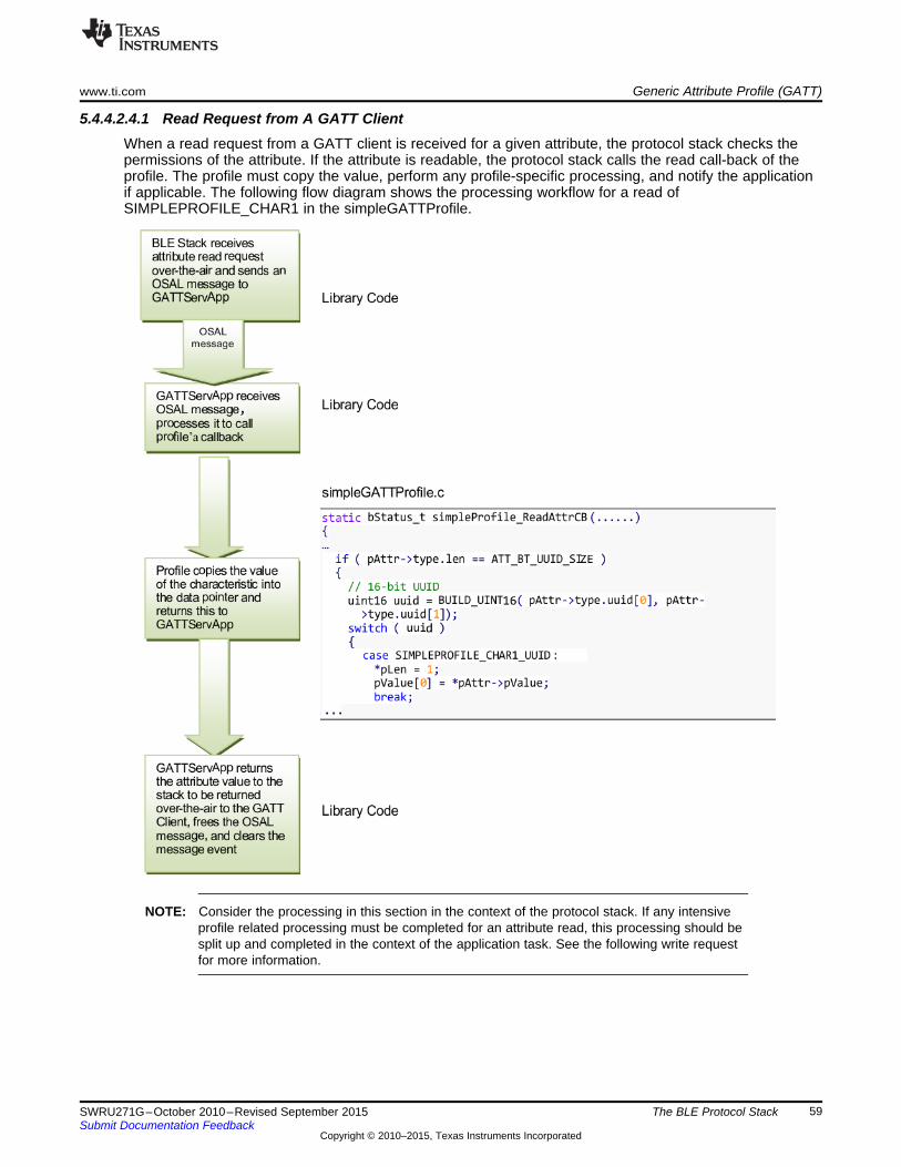
www.ti.com Generic Attribute Profile (GATT)
5.4.4.2.4.1 Read Request from A GATT ClientWhen a read request from a GATT client is received for a given attribute, the protocol stack checks thepermissions of the attribute. If the attribute is readable, the protocol stack calls the read call-back of theprofile. The profile must copy the value, perform any profile-specific processing, and notify the applicationif applicable. The following flow diagram shows the processing workflow for a read ofSIMPLEPROFILE_CHAR1 in the simpleGATTProfile.
NOTE: Consider the processing in this section in the context of the protocol stack. If any intensiveprofile related processing must be completed for an attribute read, this processing should besplit up and completed in the context of the application task. See the following write requestfor more information.
59SWRU271G–October 2010–Revised September 2015 The BLE Protocol StackSubmit Documentation Feedback
Copyright © 2010–2015, Texas Instruments Incorporated

Generic Attribute Profile (GATT) www.ti.com
5.4.4.2.4.2 Write Request from ClientWhen a write request from a GATT Client is received for a given attribute, the protocol stack will check thepermissions of the attribute. If the attribute is write, call the write callback of the profile. The profile storesthe value to be written, performs any profile-specific processing, and notifies the application if applicable.The following flow diagram illustrates a write of simpleprofileChar3 in the simpleGATTProfile. In thediagram, red corresponds to processing in the protocol stack context and green corresponds to processingin the application context.
60 The BLE Protocol Stack SWRU271G–October 2010–Revised September 2015Submit Documentation Feedback
Copyright © 2010–2015, Texas Instruments Incorporated
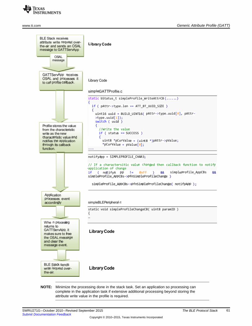
www.ti.com Generic Attribute Profile (GATT)
NOTE: Minimize the processing done in the stack task. Set an application so processing cancomplete in the application task if extensive additional processing beyond storing theattribute write value in the profile is required.
61SWRU271G–October 2010–Revised September 2015 The BLE Protocol StackSubmit Documentation Feedback
Copyright © 2010–2015, Texas Instruments Incorporated
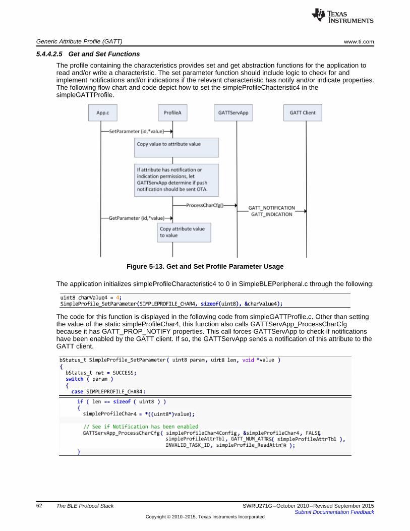
Generic Attribute Profile (GATT) www.ti.com
5.4.4.2.5 Get and Set FunctionsThe profile containing the characteristics provides set and get abstraction functions for the application toread and/or write a characteristic. The set parameter function should include logic to check for andimplement notifications and/or indications if the relevant characteristic has notify and/or indicate properties.The following flow chart and code depict how to set the simpleProfileChacteristic4 in thesimpleGATTProfile.
Figure 5-13. Get and Set Profile Parameter Usage
The application initializes simpleProfileCharacteristic4 to 0 in SimpleBLEPeripheral.c through the following:
The code for this function is displayed in the following code from simpleGATTProfile.c. Other than settingthe value of the static simpleProfileChar4, this function also calls GATTServApp_ProcessCharCfgbecause it has GATT_PROP_NOTIFY properties. This call forces GATTServApp to check if notificationshave been enabled by the GATT client. If so, the GATTServApp sends a notification of this attribute to theGATT client.
62 The BLE Protocol Stack SWRU271G–October 2010–Revised September 2015Submit Documentation Feedback
Copyright © 2010–2015, Texas Instruments Incorporated

www.ti.com L2CAP
5.5 L2CAPThe L2CAP layer sits on top of the HCI layer and transfers data between the upper layers of the host(GAP, GATT, application, and so forth) and the lower-layer protocol stack. This layer multiplexes higher-level protocol and reassembles data exchanged between the host and the protocol stack. L2CAP permitshigher-level protocols and applications to transmit and receive upper-layer data packets (L2CAP ServiceData Units, [SDUs]) up to 64KB long. The amount of memory available on the specific deviceimplementation limits the size. The CC254x and the 1.4.1 stack support an effective MTU size of 23, setby L2CAP_MTU_SIZE in l2cap.h. Changing the L2CAP_MTU_SIZE results in incorrect stack behavior.
5.6 HCIThe HCI layer is a thin layer that transports commands and events between the host and controller. In anetwork processor application, the HCI layer is implemented by a transport protocol such as SPI or UART.In embedded SoC projects, the HCI layer is implemented through function calls and callbacks. Thecommands and events discussed previously in this guide pass from the given layer through the HCI layerto the controller and through the controller to the HCI layer.
5.6.1 HCI Extension Vendor-Specific CommandsSome HCI extension vendor-specific commands extend the functionality of the controller for theapplication and host. See Appendix G for a description of HCI extension commands and examples for anSoC project.
5.6.2 Receiving HCI Extension Events in the ApplicationLike the GAP and ATT layers, the HCI extension commands result in HCI extension events being passedpassing from the controller to the host. Additional steps are required to receive these HCI extensionevents at the application.
The GAPRole task registers receive HCI Extension events in gapRole_init() by default:
The GAPRole task receives events related to HCI extension commands, even if they are called from theapplication. Implement a callback function to pass these events from the GAPRole task back to theapplication if needed in the application.
63SWRU271G–October 2010–Revised September 2015 The BLE Protocol StackSubmit Documentation Feedback
Copyright © 2010–2015, Texas Instruments Incorporated

Library Files www.ti.com
5.7 Library FilesEach project must include the following two library files:• BLE Stack Library: This library includes the lower-layer stack functionality and varies based on the
GAP role. You can include the full library, but you can use a smaller subset to conserve code spacetypically. This library is different for a CC2540 and CC2541 project.
• HCI Transport Layer Library: This library includes transport layer functionality for a network processor.This library is the same for CC2540 and CC2541.
The library files are at $INSTALL$\Projects\ble\Libraries. Use Table 5-2 to determine the correct library fileto use in the project.
Table 5-2. Supported BLE-Stack Library Configurations
GAP Roles Supported Chipset LibraryConfiguration
Broadcaster Observer Peripheral CentralNetwork X X X X CC2540 CC2540_BLE.libprocessor CC254X_BLE_H
CI_TL_Full.libSingle-device X X X X CC2540 CC2540_BLE.libSingle-device X CC2540 CC2540_BLE_b
cast.libSingle-device X X CC2540 CC2540_BLE_
bcast_observ.libSingle-device X X CC2540 CC2540_BLE_c
ent.libSingle-device X X X CC2540 CC2540_BLE_
cent_bcast.libSingle-device X CC2540 CC2540_BLE_o
bserv.libSingle-device X X CC2540 CC2540_BLE_p
eri.libSingle-device X X X CC2540 CC2540_BLE_
peri_observ.libNetwork X X X X CC2541 CC2541_BLE.libprocessor CC254X_BLE_H
CI_TL_Full.libSingle-device X X X X CC2541 CC2541_BLE.libSingle-device X CC2541 CC2541_BLE_
bcast.libSingle-device X X CC2541 CC2541_BLE_
bcast_observ.libSingle-device X X CC2541 CC2541_BLE_c
ent.libSingle-device X X X CC2541 CC2541_BLE_
cent_bcast.libSingle-device X CC2541 CC2541_BLE_
observ.libSingle-device X X CC2541 CC2541_BLE_p
eri.libSingle-device X X X CC2541 CC2541_BLE_
peri_observ.lib
64 The BLE Protocol Stack SWRU271G–October 2010–Revised September 2015Submit Documentation Feedback
Copyright © 2010–2015, Texas Instruments Incorporated

Chapter 6SWRU271G–October 2010–Revised September 2015
Drivers
The hardware abstraction layer (HAL) of the CC254x software provides an interface of abstractionbetween the physical hardware and the application and/or protocol stack. This HAL allows for thedevelopment of new hardware (such as a new PCB) without making changes to the protocol stack orapplication source code. The HAL includes software for the SPI and UART communication interfaces,AES, keys, LCD, and LEDs. The HAL drivers that support the following hardware platforms include thefollowing:• SmartRF05EB + CC2540EM• SmartRF05EB + CC2541EM• CC2540 Keyfob• CC2541 Keyfob• CC2541 SensorTag• CC2540 USB Dongle
When developing with a different hardware platform, you might need to modify the HAL source forcompatablility.
Find the HAL files in the sample projects by doing the following:1. Click HAL.2. Click Target.3. Click CC2540EB.4. Click Drivers. See Figure 6-1.
Figure 6-1. HAL Drivers
65SWRU271G–October 2010–Revised September 2015 DriversSubmit Documentation Feedback
Copyright © 2010–2015, Texas Instruments Incorporated

ADC www.ti.com
The following drivers are supported:
6.1 ADCTo include the ADC driver, define HAL_ADC=TRUE in the preprocessor definitions. See the hal_adc.hheader file for the ADC API. CC2541/43/44/45 Peripherals Software Examples (SWRC257) has severalADC examples.
6.2 AESTo include the AES driver, define HAL_AES=TRUE. The stack requires AES for encryption. Always setthis symbol set to TRUE. You cannot reuse DMA channels 1 and 2 because the AES driver uses them.Set the following in hal_aes.h:
You can find the AES API in hal_ase.h. TI recommends letting the application use the HCI encrypt anddecrypt functions (from hci.h):
6.3 LCDTo include the LCD driver, define HAL_LCD=TRUE in the preprocessor definitions. TI designed the driverto function with the LCD on the SmartRF05 boards. You must modify parts of the driver such as the pinand port definitions in hal_lcd.c to use it with custom hardware. See the CC2540/1 configuration in theSimpleBLEPeripheral project for an example using the LCD driver.
6.4 LEDTo include the LED driver, define HAL_LED=TRUE in the preprocessor definitions. TI designed the driverto function with the LEDs on the Keyfob. You must modify parts of the driver such as the LED bitdefinitions in hal_led.c to use it with custom hardware. See the CC2540/1 DK-miniKeyfob in theSimpleBLEPeripheral project for an example using the LED driver.
6.5 KEYThe KEY driver handles button inputs. To include the KEY driver, define HAL_KEY=TRUE in thepreprocessor definitions. TI designed the driver to function with the buttons on the keyfob or SmartRF05Board depending on whether CC2540_MINIDK is defined. You must modify parts of the driver such as theport and pin definitions in hal_key.c to use it with custom hardware. See the SimpleBLEPeripheral projectfor an example using the KEY driver.
6.6 DMATo include the DMA driver, define HAL_DMA=TRUE in the preprocessor definitions. Because the AESdriver uses the DMA driver, always include the DMA driver in the project. Channels 1 and 2 are reservedfor the AES driver. If the UART DMA or SPI driver is used, other channels are used. You can find theDMA API in hal_dma.h. See the SPI driver for an example of using the DMA driver.
6.7 UART and SPIDescribing the UART and SPI drivers is beyond the scope of this document. See the Device InformationService (Bluetooth Specification), version 1.0 (24-May-2011) for several UART and SPI examples,specifically the BLE serial bridge.
66 Drivers SWRU271G–October 2010–Revised September 2015Submit Documentation Feedback
Copyright © 2010–2015, Texas Instruments Incorporated

www.ti.com Other Peripherals
6.8 Other PeripheralsSee CC2541/43/44/45 Peripherals Software Examples (SWRC257) for examples of hardware peripheralswithout drivers, such as the timers. See CC254x Chip User’s Guide (SWRU191) for explanation of thehardware peripherals.
6.9 Simple NV (SNV)The SNV area of flash securely stores persistent data, such as encryption keys from bonding or customparameters. The protocol stack reserves two 2-kB flash pages for SNV. These pages are the last twopages of flash by default. To minimize the number of erase cycles on the flash, the SNV managerperforms compactions on the flash sector when the sector has 80% invalidated data. A compaction iscopying valid data to a temporary area then erasing the sector where the data was stored. The SNV driveruses the hal_flash driver.
SNV can be read from or written to using the following APIs:
uint8 osal_snv_read( osalSnvId_t id, osalSnvLen_t len, void *pBuf) Read data from NV
Parameters id – valid NV item
len – Length of data to read
pBuf – pointer to buffer to store data read
Returns SUCCESS: NV item read successfully
NV_OPER_FAILED: failure reading NV item
uint8 osal_snv_write( osalSnvId_t id, osalSnvLen_t len, void *pBuf) Write data to NV
Parameters id – valid NV item
len – Length of data to write
pBuf – pointer to buffer containing data to be written
Returns SUCCESS: NV item read successfully
NV_OPER_FAILED: failure reading NV item
Because SNV is shared with other modules in the BLE SDK such as the GAPBondMgr, carefully managethe IDs of the NV item. The available IDs are defined in bcomdef.h by default:
67SWRU271G–October 2010–Revised September 2015 DriversSubmit Documentation Feedback
Copyright © 2010–2015, Texas Instruments Incorporated

Chapter 7SWRU271G–October 2010–Revised September 2015
Creating a Custom BLE Application
After reading the preceding sections, you should understand the general system architecture, application,BLE stack framework to implement a custom Bluetooth Smart™ application. This following sectionprovides guidance on where and how to start writing a custom application and some considerations.
7.1 Configuring the BLE StackYou must decide which role and purpose the custom application should have. If the application is relatedto a specific service or profile, start with one of those. An example application includes the heart ratesensor project. TI recommends starting with one of the following SimpleBLE sample projects:• SimpleBLECentral• SimpleBLEPeripheral• SimpleBLEBroadcaster• SimpleBLEObserver
When deciding the role and purpose of the application, choose from the appropriate libraries inSection 5.7.
7.2 Define BLE BehaviorUse the BLE protocol stack APIs to define the system behavior such as adding profiles, defining the GATTdatabase, configuring the security model, and so forth. Use the concepts in Chapter 5 and the BLE APIreference in the appendices A through G of this guide.
7.3 Define Application TasksEnsure the application contains callbacks from the various stack layers and event handlers to processOSAL messages. You can add other tasks by following the guidelines in Chapter 3.
7.4 Configure Hardware PeripheralsAdd drivers as specified in Chapter 6. If drivers do not exist for a given peripheral, create a custom driver.
7.5 Configuring Parameters for Custom HardwareYou must adjust several software parameters when working with custom hardware.
7.5.1 Board FileYou can find the board file (hal_board_cfg.h) in the sample projects by doing the following:1. Click HAL.2. Click Target.3. Click CC2540EB.4. Click Config.
68 Creating a Custom BLE Application SWRU271G–October 2010–Revised September 2015Submit Documentation Feedback
Copyright © 2010–2015, Texas Instruments Incorporated

www.ti.com Configuring Parameters for Custom Hardware
Depending on the hardware platform (keyfob, EM, and so forth), the project contains a different board file.These board files are specific to the given platform and must be adjusted for custom hardware. Somemodifications may include the following:• Modifying the symbols used by drivers for specific pins (that is, LED1_SBIT)• Selecting the 32-kHz oscillator source (OSC_32KHZ)• Initializing input and output pins to safe initialization levels to prevent current leakage
7.5.2 Adjusting for 32-MHz Crystal Stabilization TimeBefore entering sleep, the stack sets the sleep timer to wake before the next BLE event. The closer thewakeup is to the event, less power is wasted. If the wakeup is too close to the even, the sleep time mightmiss the event.
When the timer wakes, it must wait for the 32-MHz external crystal to stabilize. This stabilization time isaffected by the inherent stabilization time of the crystal, how long the crystal has been off, thetemperature, the voltage, and so forth. You must add a buffer to the wakeup time (that is, start earlier) tohandle this variability in stabilization.
This buffer time is implemented using the HAL_SLEEP_ADJ_TICKS definition where the value of thedefinition corresponds to the number of 32-MHz ticks. This definition is set in hal_sleep.c to 25 for theCC2541 EM and 35 for the CC2540 EM by default. If the value of the definition is larger, the buffer time islonger and more power is wasted. Calculate this value empirically. If HAL_SLEEP_ADJ_TICKS is set toolow, false advertisement restarts and connection drops occur. If these restarts and drops occur, increasethe definition until they stop.
7.5.3 Setting the Sleep Clock AccuracyIf you must modify the sleep clock accuracy from the default (50 ppm for a master and 40 ppm for aslave), use the HCI_EXT_SetSCACmd(). See Appendix G for more information.
7.6 Software Considerations
7.6.1 Memory Management for GATT Notifications and IndicationsTI recommends using the SetParameter function (that is, SimpleProfile_SetParameter()) and callGATTServApp_ProcessCharCfg() to send a GATT notification or indication. If using GATT_Notification()or GATT_Indication() directly, you require additional memory management. For additional memorymanagement, do the following:1. Attempt to allocate memory for the notification or indication using GATT_bm_alloc().2. If allocation succeeds, send the notification or indication using GATT_Notification()/GATT_Indication().
NOTE: If the return value of the notification or indication is SUCCESS (0x00), the stack freed thememory.
If the return value is something other than SUCCESS (that is, blePending), free the memoryusing GATT_bm_free().
69SWRU271G–October 2010–Revised September 2015 Creating a Custom BLE ApplicationSubmit Documentation Feedback
Copyright © 2010–2015, Texas Instruments Incorporated

Software Considerations www.ti.com
The following is an example of this allocation in the gattServApp_SendNotiInd() function ingattservapp_util.c:
7.6.2 Limit Application Processing During BLE ActivityBecause of the time-dependent nature of the BLE protocol, the controller (LL_ProcessEvent()) mustprocess before each connection event or advertising event. If the controller does not get process,advertising restarts or the connection drops. Because OSAL is not multithreaded, each task must stopprocessing to let the controller process. The stack layers do not have this issue. Ensure that theapplication processes less than the following:(connection/advertising interval) – 2 ms
The 2 ms are added as buffer to account for controller processing time. If extensive processing is requiredin the application task, split it up using OSAL events in Section 3.2.
7.6.3 Global InterruptsDuring BLE activity, the controller must process radio and MAC timer interrupts quickly to set up the BLEevent postprocessing. Never globally disable interrupts during BLE activity.
70 Creating a Custom BLE Application SWRU271G–October 2010–Revised September 2015Submit Documentation Feedback
Copyright © 2010–2015, Texas Instruments Incorporated

Chapter 8SWRU271G–October 2010–Revised September 2015
Development and Debugging
Embedded software for the CC2540/41 is developed using Embedded Workbench for 8051 9.10.3 fromIAR software. This section provides where to find this software and contains some basics on the use ofIAR, such as opening and building projects, as well as information on the configuration of projects usingthe BLE protocol stack. IAR contains many features beyond the scope of this document. More informationand documentation is available on the IAR website: www.iar.com.
8.1 IAR OverviewTwo options are available for developing software on the CC2540/41:• Download IAR Embedded Workbench 30-day Evaluation Edition – This version of IAR is free and fully
functional for 30 days. This version includes the standard features. Download the IAR 30-dayEvaluation Edition from the following URL: http://supp.iar.com/Download/SW/?item=EW8051-EVAL
• Purchase the full-featured version of IAR Embedded Workbench – For complete BLE applicationdevelopment using the CC2540/41, TI recommends the complete version of IAR without restrictions.Information on purchasing the complete version of IAR is available at the following URL:http://www.iar.com/en/Products/IAR-Embedded-Workbench/8051/
8.2 Using IAR Embedded WorkbenchAfter installing IAR Embedded Workbench, download the latest patches from IAR. These patches arerequired to build and debug projects with the CC2540/41. When the patches have been installed, you candevelop software for the CC2540/41. This section describes how to open and build an existing project fora CC2540. Similar steps apply for a CC2541. This section uses the SimpleBLEPeripheral project as anexample. The TI BLE software development kit includes the SimpleBLEPeripheral project.
8.2.1 Open an Existing ProjectTo open an existing project when using Windows, do the following:1. Click Start.2. Click Programs.3. Click IAR Systems.4. Click IAR Embedded Workbench for 8051 9.10.5. Click IAR Embedded Workbench.
When IAR opens up, do the following:6. Click File.7. Click Open.8. Click Workspace.9. Select the following file:
$INSTALL$\Projects\ble\SimpleBLEPeripheral\CC2540DB\SimpleBLEPeripheral.eww
71SWRU271G–October 2010–Revised September 2015 Development and DebuggingSubmit Documentation Feedback
Copyright © 2010–2015, Texas Instruments Incorporated

Using IAR Embedded Workbench www.ti.com
This file is the workspace for the SimpleBLEPeripheral project. When you select this file, the filesassociated with the workspace should also open with a list of files on the left side. See Figure 8-1 for theIAR Embedded Workbench.
Figure 8-1. IAR Embedded Workbench
8.2.2 Project Options, Configurations, and Defined SymbolsEvery project has a set of options, including settings for the compiler, linker, debugger, and so forth.
To view the project options, do the following:1. Right-click on the project name at the top of the file list.
72 Development and Debugging SWRU271G–October 2010–Revised September 2015Submit Documentation Feedback
Copyright © 2010–2015, Texas Instruments Incorporated
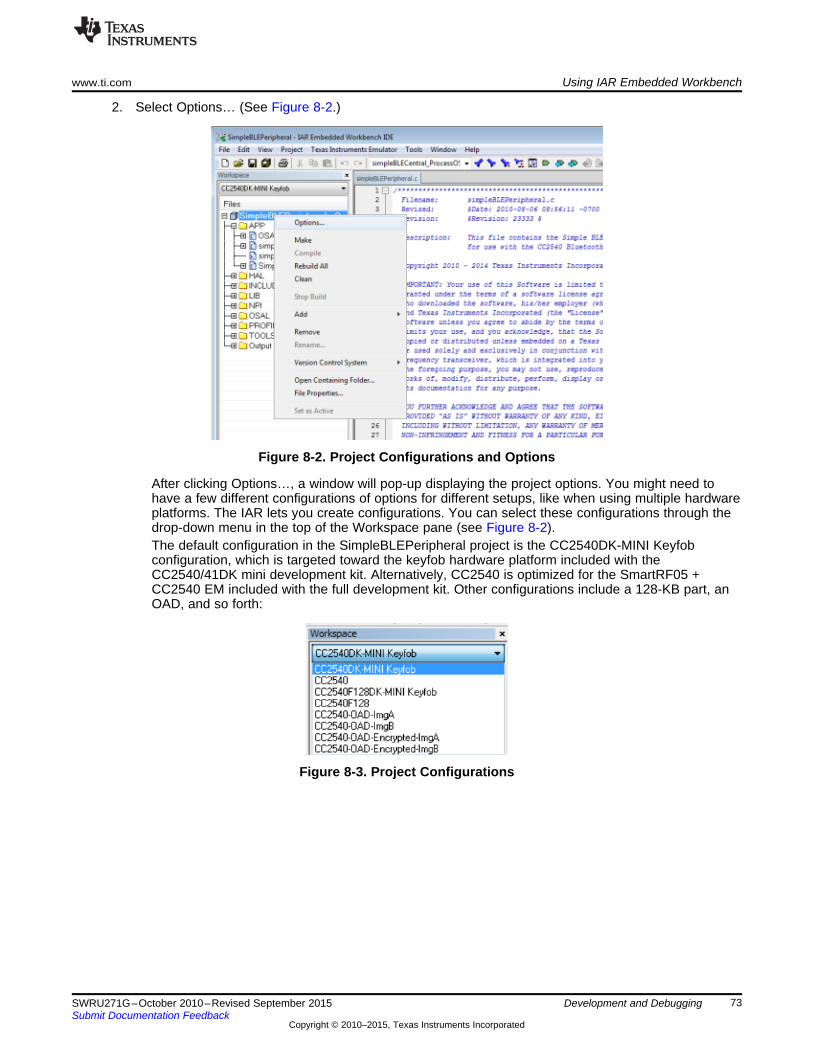
www.ti.com Using IAR Embedded Workbench
2. Select Options… (See Figure 8-2.)
Figure 8-2. Project Configurations and Options
After clicking Options…, a window will pop-up displaying the project options. You might need tohave a few different configurations of options for different setups, like when using multiple hardwareplatforms. The IAR lets you create configurations. You can select these configurations through thedrop-down menu in the top of the Workspace pane (see Figure 8-2).The default configuration in the SimpleBLEPeripheral project is the CC2540DK-MINI Keyfobconfiguration, which is targeted toward the keyfob hardware platform included with theCC2540/41DK mini development kit. Alternatively, CC2540 is optimized for the SmartRF05 +CC2540 EM included with the full development kit. Other configurations include a 128-KB part, anOAD, and so forth:
Figure 8-3. Project Configurations
73SWRU271G–October 2010–Revised September 2015 Development and DebuggingSubmit Documentation Feedback
Copyright © 2010–2015, Texas Instruments Incorporated

Using IAR Embedded Workbench www.ti.com
Compiler preprocessor definitions or symbols are important settings when building a project (see Figure 8-4).
You can find and set these values by doing the following:1. Click the C/C++ Compiler category on the left.2. Click the Preprocessor tab on the right:
Figure 8-4. Preprocessor Defined Symbols Settings
When preceded by an x, the symbol has no valid definition and can be considered disabled. Removing thepreceding x to restore the proper name of the symbol reenables the feature or definition.
74 Development and Debugging SWRU271G–October 2010–Revised September 2015Submit Documentation Feedback
Copyright © 2010–2015, Texas Instruments Incorporated

www.ti.com Using IAR Embedded Workbench
Symbols can be defined in configuration files, which are included when compiling. The Extra Options tabunder the compiler settings let you set up the configuration files to be included. You must include theconfig.cfg file with every build because it defines some required universal constants. The buildConfig.h fileincluded with the software development kit defines the appropriate symbols for the project (see Figure 8-5).
Figure 8-5. The buildConfig.h File
Select the Use command line option box through the Extra Options tab shown in Figure 8-6 to supply thecompiler with additional options.
Figure 8-6. Configuration File Setup
75SWRU271G–October 2010–Revised September 2015 Development and DebuggingSubmit Documentation Feedback
Copyright © 2010–2015, Texas Instruments Incorporated

Using IAR Embedded Workbench www.ti.com
The BLE protocol stack and software uses the following symbols. You can find them in the sample project:
Symbols Mandatory for BLE Stack• INT_HEAP_LEN – This symbol defines the size of the heap used by the OSAL Memory Manager (see
Section 3.3) in bytes. The default value in the sample project is 3072. You can increase this value ifthe application requires additional heap memory. If this value is increased too much, you may exceedthe RAM limit. If the application requires additional memory for local variables, you may need toincrease this value. The memory set aside for the heap shows up in the map file under theOSAL_Memory module. For more information on the map file, see section Section 8.2.4.
• HALNODEBUG – Define this symbol for all projects to disable HAL assertions.• OSAL_CBTIMER_NUM_TASKS – This symbol defines the number of OSAL callback timers that you
can use. The BLE protocol stack uses the OSAL callback timer. You must define this value as either 1or 2 (a maximum of two callback timers are allowed). For applications without any callback timers suchas the sample application, define this value as 1.
• HAL_AES_DMA – Define this symbol as TRUE because the BLE stack uses DMA for AES encryption.• HAL_DMA – This value must be defined as TRUE for all BLE projects, as the DMA controller is used
by the stack when reading and writing to flash.
Optional Symbols• POWER_SAVING – When defined, this symbol configures the system to go into sleep mode when free
of any pending tasks.• PLUS_BROADCASTER – This symbol indicates that the device is using the GAP
Peripheral/Broadcaster multirole profile rather than the single GAP Peripheral role profile. The defaultoption in the simpleBLEPeripheral project is undefined.
• HAL_LCD – This symbol indicates whether to include and use the LCD driver when set to TRUE. If notdefined, it is set to TRUE.
• HAL_LED – This symbol indicates whether to include the LED driver when set to TRUE. If not defined,it is set to TRUE.
• HAL_KEY – This symbol indicates whether to include the KEY driver when set to TRUE. If not defined,it is set to TRUE.
• HAL_UART – This symbol indicates whether to include the UART driver when set to TRUE. If notdefined, it is set to FALSE.
• CC2540_MINIDK – Define this symbol when using the keyfob board in the CC2540/41DK-MINIdevelopment kit. This symbol configures the hardware based on the keyfob board layout.
• HAL_UART_DMA – This symbol sets the UART interface to use DMA mode when set to 1. WhenHAL_UART is defined, set either HAL_UART_DMA or HAL_UART_ISR to 1.
• HAL_UART_ISR – This symbol sets the UART interface to use ISR mode when set to 1. WhenHAL_UART is defined, set either HAL_UART_DMA or HAL_UART_ISR to 1.
• HAL_UART_SPI – This symbol indicates whether to include the SPI driver.• GAP_BOND_MGR – The HostTestRelease network processor project uses this symbol. When this
symbol is defined for slave and peripheral configurations, use the GAP peripheral bond managersecurity profile to manage bonds and handle keys. See Section 5.3 for more information on theperipheral bond manager.
• GATT_DB_OFF_CHIP – The HostTestRelease network processor project uses this symbol. Thissymbol sets a GATT client in a network processor configuration to manage the attributes in theapplication processor instead of the CC2540/41.
Other definitions relating to specific use cases such as the serial bootloader, OAD, and so forth aredefined in the documentation.
76 Development and Debugging SWRU271G–October 2010–Revised September 2015Submit Documentation Feedback
Copyright © 2010–2015, Texas Instruments Incorporated

www.ti.com Using IAR Embedded Workbench
8.2.3 Building and Debugging a ProjectTo build a project, do the following:1. Right-click on the workspace name. See Figure 8-7.
Figure 8-7. Building a Project
2. Click Make or press F7.
NOTE: This action compiles the source code, links the files, and builds the project. Any compilererrors or warnings appear in the Build window.
3. To download the compiled code onto a CC2540/41 device and debug, connect the keyfob using ahardware debugger (such as the CC Debugger included with the CC2540/41DK-MINI development kit)connected to the PC over USB.
77SWRU271G–October 2010–Revised September 2015 Development and DebuggingSubmit Documentation Feedback
Copyright © 2010–2015, Texas Instruments Incorporated
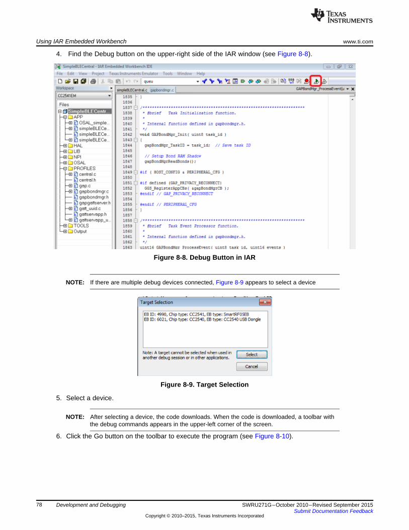
Using IAR Embedded Workbench www.ti.com
4. Find the Debug button on the upper-right side of the IAR window (see Figure 8-8).
Figure 8-8. Debug Button in IAR
NOTE: If there are multiple debug devices connected, Figure 8-9 appears to select a device
Figure 8-9. Target Selection
5. Select a device.
NOTE: After selecting a device, the code downloads. When the code is downloaded, a toolbar withthe debug commands appears in the upper-left corner of the screen.
6. Click the Go button on the toolbar to execute the program (see Figure 8-10).
78 Development and Debugging SWRU271G–October 2010–Revised September 2015Submit Documentation Feedback
Copyright © 2010–2015, Texas Instruments Incorporated

www.ti.com Using IAR Embedded Workbench
7. Click the Stop Debugging button to leave debugging mode.Figure 8-10 shows both of these buttons:
Figure 8-10. IAR Debug Toolbar
8. While the program executes, disconnect the hardware debugger from the CC2540/41.
The debugger runs while the device remains powered.
8.2.4 Linker Map FileAfter building a project, IAR generates a linker map file that you can find in the Output group in the file list.
Figure 8-11. Map File in File List
79SWRU271G–October 2010–Revised September 2015 Development and DebuggingSubmit Documentation Feedback
Copyright © 2010–2015, Texas Instruments Incorporated

Using IAR Embedded Workbench www.ti.com
The map file contains low-level information about the build. Lines of text similar to the following are at theend of the map file:
118 544 bytes of CODE memory
35 bytes of DATA memory (+ 73 absolute )
6 242 bytes of XDATA memory
194 bytes of IDATA memory
8 bits of BIT memory
4 149 bytes of CONST memory
Errors: noneWarnings: none
This text shows the total code space (CODE memory) and RAM (XDATA memory) the project uses.Ensure the sum of the CODE memory plus CONST memory does not exceed the maximum flash size ofthe device (either 128KB or 256KB, depending on the version of the CC2540/41). Ensure the size of theXDATA memory does not exceed 7936 bytes, as the CC2540/41 contains 8KB of SRAM (256 bytes arereserved).
For more specific information, the map file contains a section called MODULE SUMMARY. This section isapproximately 200 to 300 lines before the end of the file (the exact location varies from build-to-build).Within this section, you can see the exact amount of flash and memory for every module in the project.
80 Development and Debugging SWRU271G–October 2010–Revised September 2015Submit Documentation Feedback
Copyright © 2010–2015, Texas Instruments Incorporated

Chapter 9SWRU271G–October 2010–Revised September 2015
General Information
The release notes also can be found in the installer at: $INSTALL$\README.txt.
9.1 Release Notes HistoryTexas Instruments, Inc.
CC2540/41 Bluetooth low energy Software Development Kit Release Notes
Version 1.4.1 May 18, 2015
Notices:• This version of the Texas Instruments BLE stack and software is a maintenance update to the v1.4
release. It contains several bug fixes and enhancements.• The BLE protocol stack, including both the controller and host, was completely retested for v1.4.1.
Changes and minor enhancements:• All projects have been migrated from IAR v8.20.2 to IAR 9.10.3. To build all projects, upgrade to IAR
v9.10.3.• Smarter handling of connection parameter updates with multiple connections• GAPRole_SetParameter(GAPROLE_ADVERT_DATA) changes the advertising data• Allows removal of Service Changed Characteristic• HAL components set to TRUE if not defined• Added HCI Vendor Specific Guide revision history• Several bug fixes
Bug Fixes:• Fix for RSSI value does not change in V1.4 stack• Fix for Number HCI Commands parameter not updated in Command Complete Event• Fixed CC254x UART DMA reception discontinuity• Fix for updating advertisement data while simultaneously connected as peripheral and advertising• Fix for filtering duplicate ADV reports even when the filter is FALSE• Fix for possible race condition T2ISR vs T2E1 on slow wakeups• Fix for HAL_DMA_CLEAR_IRQ() can be interrupted causing missed ISR cause• Fixed HCI_LERemoveDeviceFromWhiteList Fails after Scan• Watchdog Kick Macro Affected by Interrupts• Fixed HCI_EXT_ResetSystem soft reset to work as expected on CC254x• Fixed White List Irregularities During Scan / Connect• Fixed Overlap processing that causes Slave task to last too long for next event setup• Add BTool Support for new field 'encKeySize' added to GATT_AddService command• Fixed CC254x UART DMA reception discontinuity• Fixed CC254x unresponsive when resetting in initiating state• Fix for after successful reconnect using private non-resolvable address, rebond fails with "Key Req
Rejected"
81SWRU271G–October 2010–Revised September 2015 General InformationSubmit Documentation Feedback
Copyright © 2010–2015, Texas Instruments Incorporated

Release Notes History www.ti.com
• Fix for CC254x host Bond Manager setParam configuration does not support M/S LinkKey encexchange
• Fixed TICKSPD, CLKSPD is overwritten on X/HS-OSC change• Fixed Device Fails to Return to Sleep After Last BLE Task
Known Issues:• Use of the NV memory (to save application data or BLE Host bonding information) during a BLE
connection may cause an unexpected disconnect. The likelihood of this happening increases withfrequent usage, especially when using short connection intervals. The cause is related to the NV wearalgorithm which at some point may cause an NV page erase which can disrupt system real-timeprocessing. TI recommends using the NV memory sparingly or only when a connection is not active.
• HCI packet size of 128 bytes or more will be disregarded by the stack and no HCI event will bereturned.
For technical support, visit the Texas Instruments Bluetooth low energy E2E Forum: http://www.ti.com/ble-forum
For additional sample applications, guides, and documentation, visit the Texas Instruments Bluetooth lowenergy wiki page at: http://processors.wiki.ti.com/index.php/Category:BluetoothLE
------------------------------------------------------------------------------------------
------------------------------------------------------------------------------------------
Texas Instruments, Inc.
CC2540/41 Bluetooth low energy Software Development Kit Release Notes
Version 1.4.0 November 8, 2013
Notices:• This version of the Texas Instruments BLE stack and software is a minor update to the v1.3.2 release.
It contains some minor bug fixes and a few functional changes.• The BLE protocol stack, including both the controller and host, was completely retested for v1.4.0.
Changes and Enhancements:• All projects have been migrated from IAR v8.10.4 to IAR 8.20.2.To build all projects, upgrade to IAR
v8.20.2.• Updated SPI and UART_DMA drivers for improved robustness and throughput.• Added an overlapped processing feature to improve throughput and reduce power consumption in
devices where peak power consumption isn't an issue. Overlapped processing allows the stack toconcurrently process while the radio is active. Since the stack is concurrently processing, it is able toinsert new data in the Tx buffer during the connection event, causing additional packets to be sentbefore the end of the event.
• Added a Number of Completed Packets HCI command which offers the possibility of waiting for acertain number of completed packets before reporting to the host. This allows higher throughput whenused with overlapped processing.
• Added an HCI Extension command HCI_EXT_DelaySleepCmd which provides the user control of thesystem initialization sleep delay (wake time from PM3/boot before going back to sleep). The defaultsleep delay is based on the reference design 32 kHz XOSC stabilization time.
• Added a low duty cycle directed advertising option.• Added support for deleting a single bond with the GAP_BondSetParam command.• Decreased CRC calculation time during OAD by using DMA.
82 General Information SWRU271G–October 2010–Revised September 2015Submit Documentation Feedback
Copyright © 2010–2015, Texas Instruments Incorporated

www.ti.com Release Notes History
Bug Fixes:• Using a short connection interval and exercising high throughput, there was some loss of packets. This
was fixed by adding host to application flow control support.• Bonding was unstable at short connection intervals. This is now fixed.• Fixed USB CDC Drivers to work with Windows 8.• OAD sample project would fail if long connection interval was used. This was fixed by not allowing
parameter updates to the central device.• Fixed linking errors in UBL project.• Fixed minor issues in sample apps to work with PTS dongle.• Fixed USB descriptors in HostTestRelease to display correct string.
Known Issues:• Use of the NV memory (to save application data or BLE Host bonding information) during a BLE
connection may cause an unexpected disconnect. The likelihood of this happening increases withfrequent usage, especially when using short connection intervals. The cause is related to the NV wearalgorithm which at some point may cause an NV page erase which can disrupt system real-timeprocessing. It is therefore recommended that the NV memory be used sparingly, or only when aconnection is not active.
• HCI packet size of 128 bytes or more will be disregarded by the stack, and as such, no HCI event willbe returned.
For technical support, visit the Texas Instruments Bluetooth low energy E2E Forum:http://e2e.ti.com/support/low_power_rf/f/538.aspx
For additional sample applications, guides, and documentation, visit the Texas Instruments Bluetooth lowenergy wiki page at: http://processors.wiki.ti.com/index.php/Category:BluetoothLE
-------------------------------------------------------------------------------
-------------------------------------------------------------------------------
Version 1.3.2 June 13, 2013
Notices:• This version of the Texas Instruments BLE stack and software is a minor update to the v1.3.1 release.
It contains some minor bug fixes and a few functional changes.• The BLE protocol stack, including both the controller and host, was completely retested for v1.3.2. The
profiles Running Speed and Cadence, Cycling Speed and Cadence, and Glucose were fully tested andpassed certification. Other profiles with no code changes since 1.3.1 were sanity tested only.
Changes and Enhancements:• Added Running Speed and Cadence profile and service. An example application demonstrating
running speed and cadence is provided.• Added Cycling Speed and Cadence profile and service. An example application demonstrating cycling
speed and cadence is provided.• Added delay before performing Connection Parameter changes. Implemented conn_pause_peripheral)
and TGAP(conn_pause_central) timers as described in CSA 3 rev 2, Gap Connection ParametersChanges, Section 1.12. Updated HIDAdvRemote, HIDEmuKbd, KeyFob, SensorTag, andSimpleBLEPeripheral applications.
• Update Privacy Flag and Reconnection Address characteristics permissions (Erratum 4202)• A new Windows USB CDC driver has been included in the installer. This new driver is signed and is
functional on Windows 8 systems.
83SWRU271G–October 2010–Revised September 2015 General InformationSubmit Documentation Feedback
Copyright © 2010–2015, Texas Instruments Incorporated

Release Notes History www.ti.com
Bug Fixes:• Some minor updates to glucose sensor and collector were made.• The gyroscope would draw continuous 6mA when enabled. The updated code now performs a read
and turns off the gyro after 60ms.• The master’s host would accept invalid connection parameters requested by the Slave, and would
send back the Connection Parameter Update Response with ‘parameters accepted’. The host nowperforms validation on these parameters.
• When coming out of sleep, the HCI_EXT_ExtendRfRangeCmd would overrideHCI_EXT_SetRxGainCmd setting and set it to default gain. This has been fixed.
Known Issues:• Use of the NV memory (to save application data or BLE Host bonding information) during a BLE
connection may cause an unexpected disconnect. The likelihood of this happening increases withfrequent usage, especially when using short connection intervals. The cause is related to the NV wearalgorithm which at some point may cause an NV page erase which can disrupt system real-timeprocessing. It is therefore recommended that the NV memory be used sparingly, or only when aconnection is not active.
• HCI packet size of 128 bytes or more will be disregarded by the stack, and as such, no HCI event willbe returned.
• The HAL SPI driver that was implemented since the v1.3 release can sometimes hang, particularly incases in which power management is used and when there is heavy traffic on the SPI bus.
For technical support, visit the Texas Instruments Bluetooth low energy E2E Forum:http://e2e.ti.com/support/low_power_rf/f/538.aspx
-------------------------------------------------------------------------------
-------------------------------------------------------------------------------
Version 1.3.1 April 18, 2013
Notices:• This version of the Texas Instruments BLE stack and software is a minor update to the v1.3 release. It
contains some minor bug fixes, with no major functional changes. It also contains two additionalprojects for the CC2541 Advanced Remote Control Kit.
• Since none of the profile source code was significantly changed since the v1.3 release, no additionalre-testing of the profiles and sample application were done for v1.3.1. The only exception is the HID-over-GATT profile, which was fully re-tested for this release. The BLE protocol stack, including both thecontroller and host, was completely retested for v1.3.1.
Major Changes and Enhancements:• The GAP parameter TGAP_LIM_ADV_TIMEOUT now uses units of seconds instead of milliseconds.• The HidAdvRemote Project has been added. This implements a full mouse-like pointing functionality
using motion and gesture control. The project runs on the CC2541 BLE Advanced Control included aspart of the CC2541DK-REMOTE kit. The application implements the HID-over-GATT (HOGP) profilewith a report descriptor supporting the keyboard, mouse, and consumer control classes of HID devices.
• The HidAdvRemoteDongle project has been added. This application runs on the CC2540USB dongle,and implements partial functionality of HID-over-GATT (HOGP) host with a fixed report descriptor tomatch that of the descriptor of the HidAdvRemote Project. This means that the HidAdvRemoteDonglewas designed only to work with the HidAdvRemote, and will not be compatible with any other HOGPdevices. This project was created to allow users who are using a host device that does not have nativeBluetooth Smart Ready support and/or does not have HOGP support to use the BLE AdvancedRemote Control with their system.
• For GAP central role applications, the bond manager now properly handles cases in which theperipheral device has erased previously stored bonding information
• A new HCI extension API has been added to allow peripheral/slave devices to temporarily ignore anynonzero slave latency value, and explicitly wake up at every connection event regardless of whether ithas any data to send. The prototype for the API function HCI_EXT_SetSlaveLatencyOverrideCmd canbe found in hci.h, including the description of the function.
84 General Information SWRU271G–October 2010–Revised September 2015Submit Documentation Feedback
Copyright © 2010–2015, Texas Instruments Incorporated

www.ti.com Release Notes History
• A new HCI extension API has been added to allow the application layer to get or set a build revisionnumber.
Bug Fixes:• In some cases L2CAP Peripheral Connection Parameter Update requests failed due to a zero value in
the transmitWindowOffset parameter when the connection was initially established. This has been fixedand updates should now work successfully.
• During bonding, connection failures would occasionally occur due to the OSAL Simple NV driverperforming a page compaction and halting the CPU for longer than the time required for the link layerto maintain proper connection timing. To prevent this from occurring, the simple NV driver now has anyAPI to force a page compaction if the page is full beyond a specified threshold. The bond managercalls this API every time a connection is terminated to ensure that compaction occurs before the nextconnection is set up.
• Occasional slave connection failures would previously occur in cases in which the master device sendsUpdate Channel Map requests while a large slave latency value is in use. This has been fixed.
• The SensorTag application now properly supports storage of GATT Client Characteristic ConfigurationDescriptor values with bonded devices.
• After disabling advertising, the CC254x would unnecessarily wake up for a short period of time 500mslater. This unecessary wake-up has been removed.
• Upon Power-On Reset or after wake-up from PM3, a 400ms delay has been implemented, duringwhich time the CC254x will not go into PM2 sleep. This allows time for the 32kHz crystal to stabilize.Previously, in rare cases with certain hardware configurations the CC254x could have timing issuesdue to the crystal not having time to stabilize.
• Minor bug fixes to GlucoseSensor and GlucoseCollector projects.
Known Issues:• Use of the NV memory (to save application data or BLE Host bonding information) during a BLE
connection may cause an unexpected disconnect. The likelihood of this happening increases withfrequent usage, especially when using short connection intervals. The cause is related to the NV wearalgorithm which at some point may cause an NV page erase which can disrupt system real-timeprocessing. It is therefore recommended that the NV memory be used sparingly, or only when aconnection is not active.
• HCI packet size of 128 bytes or more will be disregarded by the stack, and as such, no HCI event willbe returned.
• The HAL SPI driver that was implemented since the v1.3 release can sometimes hang, particularly incases in which power management is used and when there is heavy traffic on the SPI bus.
For technical support, visit the Texas Instruments Bluetooth low energy E2E Forum:http://e2e.ti.com/support/low_power_rf/f/538.aspx
-------------------------------------------------------------------------------
-------------------------------------------------------------------------------
Version 1.3 Dec 12, 2012
Notices:• This version of the Texas Instruments BLE stack and software features several changes,
enhancements, and bug fixes from v1.2.1. Details of these can be found below.
Changes and Enhancements:• A new sample project, SensorTag, has been added. This application runs on the CC2541 Sensor Tag
board, which is included as part of the CC2541DK-SENSOR development kit. The application includescustom services for an accelerometer, barometer, gyro, humidity sensor, IR temperature sensor, andmagnetometer.
• A new Boot Image Manager (BIM) is included. This allows one CC2540 or CC2541 device to containtwo separate software images (an "A" image and a "B" image) stored in flash. Upon power-up, the BIMselects which image to boot into. This can be based on criteria such as the state of a GPIO pin, orbased on a selection from the previously running application upon reset.
85SWRU271G–October 2010–Revised September 2015 General InformationSubmit Documentation Feedback
Copyright © 2010–2015, Texas Instruments Incorporated

Release Notes History www.ti.com
• A new Over-the-air firmware download (OAD) feature is included. The feature allows a peer device(which could be a central BT Smart device such as a smartphone) to push a new firmware image ontoa peripheral device and update the firmware. This feature uses the BIM, in which case the downloadedimage gets stored in the opposite flash location as the currently running image. For example, if the "A"image is the current image and is used to perform the download, then the downloaded image becomesthe "B" image. Upon reset, the "B" image with the updated firmware would be loaded. The OAD featureoptionally allows for the firmware image to be signed (using AES). Both the SensorTag andSimpleBLEPeripheral projects include configurations for using the OAD feature. A central"OADManager" application is also included, demonstrating a central implementation for sending a newfirmware image to an OAD target device.
• The physical HCI interface used by the network processor (HostTestRelease) has been enhanced towork while power management is enabled on the CC254x device. The UART interface, when usingRTS and CTS lines, can be used by an external application processor to wake-up the CC254x networkprocessor. When the network processor has completed all processing, it will go into deep sleep. Inaddition to UART, an SPI interface has been added as an option for the physical HCI interface. It alsosupports power management by means of the MRDY and SRDY lines.
• The CC2541 configuration of the KeyFobDemo project has been modified to support the new CC2541keyfob hardware, contained in the CC2541DK-MINI kit. The accelerometer has been changed, and aTPS62730 DC/DC converter has been added.
• The structure of all projects have been changed to include a Transport Layer ("TL") library and networkprocessor interface "NPI" source code. This new architecture allows for non-network processorapplications to have slightly reduced code size by removing unnecessary stack components.
• An API has been provided allowing the device name and appearance characteristics in the GAPservice to be modified by the application layer.
• KeyFobDemo project now includes visual feedback from LED to indicate when device has powered upand when device is advertising.
• The HID-over-GATT Profile (HOGP) implementation has been updated to now queue up HID reportand send notifications upon reconnection to a HID host.
• A new implementation of the HID service has been included, which supports a combined keyboard,mouse, and consumer class device in its HID report descriptor.
• The API for sending L2CAP Connection Parameter Update Requests from the GAP Peripheral RoleProfile has been updated to take both the requested minimum and maximum connection intervals asparameters.
• BTool has been enhanced with a new GATT explorer table, displaying discovered attributes, handles,and values. An XML file is included which allows the user to define descriptions of characteristicsbased on their UUIDs.
• HCI UART interface baud rate has been changed from 57600 to 115200.
86 General Information SWRU271G–October 2010–Revised September 2015Submit Documentation Feedback
Copyright © 2010–2015, Texas Instruments Incorporated

www.ti.com Release Notes History
Bug Fixes:• When power management is used with long connection intervals (>2s), the CC254x remains sleeping
properly without unnecessary wake-ups.• When slave latency is used, peripheral devices now properly wake-up before the next connection
event when a data packet is queued• Various bug fixes on the GlucoseSensor and GlucoseCollector projects to improve compliance with
profile and service specifications.• HID-over-GATT Pofile (HOGP) implementation has been updated to provide better interoperability with
HID hosts.
Known Issues:• Use of the NV memory (to save application data or BLE Host bonding information) during a BLE
connection may cause an unexpected disconnect. The likelihood of this happening increases withfrequent usage, especially when using short connection intervals. The cause is related to the NV wearalgorithm which at some point may cause an NV page erase which can disrupt system real-timeprocessing. It is therefore recommended that the NV memory be used sparingly, or only when aconnection is not active.
• HCI packet size of 128 bytes or more will be disregarded by the stack, and as such, no HCI event willbe returned.
For technical support, visit the Texas Instruments Bluetooth low energy E2E Forum:http://e2e.ti.com/support/low_power_rf/f/538.aspx
-------------------------------------------------------------------------------
-------------------------------------------------------------------------------
Version 1.2.1 Apr 13, 2012
Notices:• This version of the Texas Instruments BLE stack and software is a minor update to the v1.2 release. It
contains some minor enhancements and bug fixes, with no API changes or major functional changes.
Changes and Enhancements:• When advertising is enabled by calling GAP_MakeDiscoverable, the first advertisement event will now
occur within a few milliseconds, rather than waiting for 10 ms.
Bug Fixes:• The HidEmuKbd project now properly implements the HID Service include of the Battery Service. This
bug fix allows for proper interoperability between the CC254x HID Profile and host systems runningWindows 8.
• The source code file hal_board_cfg.h has been updated to better support the serial bootloader (SBL)and Universal Bootloader (UBL).
• Scanning in BTool can now be cancelled at any time without hanging or freezing the system.
Known Issues:• Use of the NV memory (to save application data or BLE Host bonding information) during a BLE
connection may cause an unexpected disconnect. The likelihood of this happening increases withfrequent usage, especially when using short connection intervals. The cause is related to the NV wearalgorithm which at some point may cause an NV page erase which can disrupt system real-timeprocessing. It is therefore recommended that the NV memory be used sparingly, or only when aconnection is not active.
For technical support, visit the Texas Instruments Bluetooth low energy E2E Forum:http://e2e.ti.com/support/low_power_rf/f/538.aspx
-------------------------------------------------------------------------------
-------------------------------------------------------------------------------
87SWRU271G–October 2010–Revised September 2015 General InformationSubmit Documentation Feedback
Copyright © 2010–2015, Texas Instruments Incorporated

Release Notes History www.ti.com
Version 1.2 Feb 13, 2012
Notices:• This version of the Texas Instruments BLE stack and software includes support for the CC2541, as
well as some enhancements and bug fixes. Details of these can be found below. If you have notpreviously worked with the v1.1b release (which had limited distribution), TI recommends you also readthe notes detailing the changes and enhancements from v1.1a to v1.1b in addition to the notes forv1.2.
Changes and Enhancements:• All projects have been migrated from IAR v7.60 to IAR v8.10.4. In order to build all projects, be sure to
upgrade and have IAR v8.10.4. Also, be sure to download and install all of the latest patches from IARfor full CC2540 and CC2541 support.
• Multi-role and combo-role support has been enhanced. The BLE stack can now support simultaneouslyadvertising and/or scanning while in a connection as either a master or a slave. This allows for acentral device to perform device discovery while in a connection. All previous rules for multiplesimultaneous connections as a central device still apply (see v1.1a release notes).
• New sample projects "SimpleBLEBroadcaster" and "SimpleBLEObserver" have been added, asexample projects for pure broadcaster and observer applications with very low code size. The projectsmake use of new GAP role profiles broadcaster.c and observer.c that are included.
• All projects have a modified architecture from the v1.1, v1.1a, and v1.1b releases. Each projectcontains a file "buildConfig.cfg" that can be found in the project directory and is included in the IARproject workspace as part of the "TOOLS" group. The settings in this file determine the role of thedevice in the application. Based on this configuration, different pieces of the BLE stack in object codeare linked in, causing the code size to be larger or smaller depending on the roles supported. Forexample, HostTestRelease by default is now configured to support every single BLE GAP role in asingle build, and therefore has a large code size (approx. 165kB). On the other hand,SimpleBLEBroadcaster is configured to only support the GAP broadcaster role, and therefore has avery small code size (approx. 39kB).
• The function GAPRole_SendUpdateParam in peripheral.c has been made public to allow a peripheralapplication to send an L2CAP connection parameter update request at any time.
• The names and configuration of the BLE stack libraries have changed. Different libraries are useddepending on the GAP role (or combination of roles) used by the application. More information can befound in section 3.3.5 of the BLE Software Developer's Guide.
• All library files now support power management. Power management must be enabled by theapplication by calling osal_pwrmgr_device( PWRMGR_BATTERY );. All sample applications that usepower management make this call in the main function.
• All GATT service source code has been cleaned up to make handling of client characteristicconfiguration descriptors (CCCDs) simpler. All CCCDs are now processing is now handled byGATTServApp and no longer must be handled by the service itself. Examples of this can be found inthe included example services such as simpleGATTprofile, Simple Keys service, Accelerometerservice, etc...
• The HostTestRelease network processor project now includes HCI Vendor Specific commands foreach GATT client sub-procedure, matching the GATT client API. All GATT commands have beenadded to the "Adv. Commands" tab in BTool. The functions in the BTool GUI "Read / Write" tab nowmake use of the GATT commands as opposed to ATT commands.
• The old "EmulatedKeyboard" project has been removed and replaced with the new "HIDEmuKbd"project. The new project performs the same functions as the old one, but is now based on the "HIDover GATT Profile" v1.0 specification (HOGP_SPEC_V10) that has been adopted by the BluetoothSIG. The HID profile functionality has been implemented in a OSAL task that runs separate from theapplication to allow for easy portability to other HID projects. More details on the new application canbe found in the BLE Sample Application Guide included as part of the release. The following additionalnew services / profiles have been included to fully support the HOGP specification:– HID Service v1.0 (HIDS_SPEC_V10)– Scan Parameters Profile v1.0 (ScPP_SPEC_V10)– Scan Parameters Service v1.0 (ScPS_SPEC_V10)
88 General Information SWRU271G–October 2010–Revised September 2015Submit Documentation Feedback
Copyright © 2010–2015, Texas Instruments Incorporated

www.ti.com Release Notes History
– Device Information Service v1.1 (DIS_SPEC_V11r00)– Battery Service v1.0 (BAS_SPEC_V10)
• The KeyFobDemo project has been updated to use the adopted battery service. The custom batteryservice that was used in previous released has been removed.
• The TimeApp project has been updated to include support for the Phone Alert Status Profile(PASP_SPEC_V10) in the Client role.
• Support for "Production Test Mode" has been added, allowing a BLE application in a "single-chip"configuration to temporarily expose the HCI over the UART interface when triggered externally to do so(e.g. hold a GPIO pin low during power up). This allows the device to be connected to a Bluetoothtester in order to run direct test mode (DTM) commands on a production line using the final releasefirmware, while leaving the UART GPIO pins available for the application to use at all other times
• A Universal Boot Loader (UBL) using the USB Mass Storage Device (USB-MSD) class has beenadded along with a Serial Boot Loader (SBL). The HostTestRelease project includes configurationswith examples of both boot loaders. The SBL project is included with the installer. More information onthe UBL can be found in the following document: C:\Texas Instruments\BLE-CC254x-1.2\Documents\Universal Boot Loader for SOC-8051 by USB-MSD Developer's Guide.pdf
• HCI extension command HCI_EXT_MapPmIoPortCmd added to support toggling of a GPIO line asCC254x device goes in and out of sleep. This command can be used to automatically control thebypass line of the TPS62730 DC/DC converter for reducing power consumption in an optimizedmanner.
• A slave device will now dynamically widen it's Rx window when a previous connection event wasmissed. This improves connection stability by accounting for additional clock drift that may haveoccurred since the last successful connection event.
• The application now has the capability to change the permissions of the device name in the GAPservice by calling GGS_SetParameter and changing the value of the parameterGGS_W_PERMIT_DEVICE_NAME_ATT. The application can also receive a callback when a clientdevice writes a new name to the device. The application registers the callback by callingGGS_RegisterAppCBs. The prototype for GGS_RegisterAppCBs can be found in gapgattserver.h.
Bug Fixes:• Duplicate filtering now works with combination states.• Various minor application / profile bug fixes.
Known Issues:• Use of the NV memory (to save application data or BLE Host bonding information) during a BLE
connection may cause an unexpected disconnect. The likelihood of this happening increases withfrequent usage, especially when using short connection intervals. The cause is related to the NV wearalgorithm which at some point may cause an NV page erase which can disrupt system real-timeprocessing. It is therefore recommended that the NV memory be used sparingly, or only when aconnection is not active.
For technical support, visit the Texas Instruments Bluetooth low energy E2E Forum:http://e2e.ti.com/support/low_power_rf/f/538.aspx
-------------------------------------------------------------------------------
-------------------------------------------------------------------------------
Version 1.1b Nov 30, 2011
Notices:• This version of the Texas Instruments BLE stack and software includes support for the CC2541, as
well as some minor enhancements and bug fixes. Details of these can be found below. The generalsoftware architecture remains the same as in the v1.1 and v1.1a releases.
Changes and Enhancements:• BLE stack libraries for the CC2541 are included.• All BLE libraries are renamed and now indicate whether they are used for CC2540 or CC2541.• For each project and configuration, new IAR projects are included for use with the CC2541. The only
89SWRU271G–October 2010–Revised September 2015 General InformationSubmit Documentation Feedback
Copyright © 2010–2015, Texas Instruments Incorporated

Release Notes History www.ti.com
exception is that any project/configuration that uses the USB interface has not been replicated for theCC2541, as it does not have an on-chip hardware USB interface.
• Link-layer processing has been optimized to provide for reduced power consumption during connectionevents and advertising events.
• SimpleBLEPeripheral and SimpleBLECentral now use the HCI_EXT_ClkDivOnHaltCmd, which reducesthe current level while the CC2540/41 radio is active.
• The bond manager has been updated to allow peripheral devices to properly pair, bond, and resolvethe address of central devices that use the private resolvable address type.
• New command HCI_EXT_SetMaxDtmTxPowerCmd included, which allows the maximum Tx powerlevel to be set. This is useful when using Direct Test Mode (DTM), in that the Tx power level will be setto the maximum value set by the HCI_EXT_SetMaxDtmTxPowerCmd command, which may be lessthan +4dBm for the CC2540 and less than 0dBm for the CC2541. The function prototype can be foundin hci.h.
Bug Fixes:• The command HCI_EXT_SetTxPowerCmd is now properly working.
Known Issues:• Use of the NV memory (to save application data or BLE Host bonding information) during a BLE
connection may cause an unexpected disconnect. The likelihood of this happening increases withfrequent usage, especially when using short connection intervals. The cause is related to the NV wearalgorithm which at some point may cause an NV page erase which can disrupt system real-timeprocessing. It is therefore recommended that the NV memory be used sparingly, or only when aconnection is not active.
• Duplicate filtering does not work when scan is used in combination with a connection.
For technical support, visit the Texas Instruments Bluetooth low energy E2E Forum:http://e2e.ti.com/support/low_power_rf/f/538.aspx
90 General Information SWRU271G–October 2010–Revised September 2015Submit Documentation Feedback
Copyright © 2010–2015, Texas Instruments Incorporated

www.ti.com Release Notes History
-------------------------------------------------------------------------------
-------------------------------------------------------------------------------
Version 1.1a Aug 10, 2011
Changes and Enhancements:• The thermometer profile sample application has been updated to support stored measurements. The
TI_BLE_Sample_Applications_Guide has been updated to match these changes.
Known Issues:• Use of the NV memory (to save application data or BLE Host bonding information) during a BLE
connection may cause an unexpected disconnect. The likelihood of this happening increases withfrequent usage, especially when using short connection intervals. The cause is related to the NV wearalgorithm which at some point may cause an NV page erase which can disrupt system real-timeprocessing. It is therefore recommended that the NV memory be used sparingly, or only when aconnection is not active.
• Duplicate filtering does not work when scan is used in combination with a connection.
For technical support, visit the Texas Instruments Bluetooth low energy E2E Forum:http://e2e.ti.com/support/low_power_rf/f/538.aspx
-------------------------------------------------------------------------------
-------------------------------------------------------------------------------
Version 1.1 July 13, 2011
Notices:• This version of the Texas Instruments BLE stack and software features several changes,
enhancements, and bug fixes from v1.0. Details of these can be found below.
Changes and Enhancements:• All projects have been migrated from IAR v7.51A to IAR v.7.60. In order to build all projects, be sure to
upgrade and have IAR v7.60. Also, be sure to download and install all of the latest patches from IARfor full CC2540 support.
• The stack now supports up to 3 simultaneous connection as a central / master device, with a fewconstraints:– All connection intervals must be a multiple of the minimum connection interval (i.e. the minimum
connection interval is the greatest common denominator of all connection intervals).– The minimum connection interval allowed is 25ms when using more than one connection.– When more than one connection is active, only one data packet per connection event will be
allowed in each direction.– Scanning is not supported while in a connection. The consequences of this is that device discovery
is not possible while in a connection. Therefore, to discover and connect to multiple devices, thedevice discovery must occur before the first connection is established.
• Several new sample projects are included, with examples of many different BLE applications / profiles.Full details on the sample applications can be found in the BLE Sample Applications Guide, which canbe accessed from the Windows Start Menu. These sample applications implement various functions.Some are based on adopted Bluetooth specifications, some are based on draft specifications, andothers are custom designed by Texas Instruments. These projects should serve as good examples forvarious other BLE applications.
• The following updates have been made to BTool (more information on these updates can be found inthe CC2540DK-MINI User Guide which can be downloaded here: SWRU270):– Improved GUI and robustness.– All functions on the GUI been updated to handle multiple simultaneous connections.– A new "Pairing / Bonding" tab has been added, allowing link encryption and authentication, passkey
entry, and saving / loading of long-term key data (from bonding) to file.– Ability to "Cancel" a link establishment while the dongle is initiating.
91SWRU271G–October 2010–Revised September 2015 General InformationSubmit Documentation Feedback
Copyright © 2010–2015, Texas Instruments Incorporated

Release Notes History www.ti.com
• The following additional new controller stack features are included in this release:– Support for multiple simultaneous connections as a master (details above)– HCI Vendor Specific function HCI_EXT_SetSCACmd allows you to specify the exact sleep clock
accuracy as any value from 0 to 500 PPM, in order to support any crystal accuracy with optimalpower consumption. This feature is only available for slave / peripheral applications.
– HCI Vendor Specific function HCI_EXT_SetMaxDtmTxPowerCmd allows you to set the maximumtransmit output power for Direct Test Mode. This allows you to perform use the LE Transmitter Testcommand with power levels less than +4dBm.
– A master device can now advertise while in a connection.– New production test mode (PTM) has been added allowing the CC2540 to run Direct Test Mode
(DTM) while connected to a tester using a "single-chip" BLE library.– The controller now uses DMA to more efficiently encrypt and decrypt packets. All BLE projects
must now define HAL_AES_DMA=TRUE in the preprocessor settings when using the v1.1 libraries.• The following additional new host stack features are included in this release:
– A new GAP central role profile for single-chip embedded central applications is included, withfunctions similar to the GAP peripheral role profile. The SimpleBLECentral project serves as anexample of an application making use of the central role profile.
– The GAP peripheral role has been optimized to significantly improve power consumption whileadvertising with small amounts of data by no longer transmitting non-significant bytes from in theadvertisement and scan response data.
• The following additional new application / profile features are included in this release:– The GAP peripheral bond manager has been replaced with a general GAP bond manager, capable
of managing bond data for both peripheral and central role devices. The gap peripheral bondmanager has been included for legacy support; however it is recommend to switch to the generalGAP bond manager (gapbondmgr.c/h).
– The bond manager also now manages the storage of client characteristic configurations for eachbond as per the Bluetooth 4.0 spec.
– The simple GATT profile has a new fifth characteristic. This characteristic is 5 bytes long, and hasreadable permissions only while in an authenticated connection. It should serve as a reference fordevelopment of other profiles which require an encrypted link.
– All GATT profiles have been updated to properly handle client characteristic configurations for bothsingle and multiple connections. Characteristic configurations now get reset to zero (notifications /indications off) after a connection is terminated, and the bond manager now stores clientcharacteristic configurations for bonded devices so that they are remembered for next time whenthe device reconnects.
– Added linker configuration file for support of 128kB flash versions of the CC2540. An example isincluded in the SimpleBLEPeripheral project.
– The SimpleBLEPeripheral project "CC2540 Slave" configuration has been updated to better supportthe SmartRF05EB + CC2540EM hardware platform, making use of the LCD display.
Bug Fixes:• The following bugs have been fixed in the controller stack:
– Scanning now working for master devices with power savings enabled.– RSSI reads no longer require a data packet to update.– Improved stability when using very high slave latency setting– HCI LE direct test modes now working properly.– HCI Read Local Supported Features now returns the proper value.– Use of two advertising channels now works.– When connecting to a device on the whitelist, the correct peer device address is returned to the
host.• The following bugs have been fixed in the host stack:
– Pairing no longer fails when either device is using a static, private resolvable, or private non-
92 General Information SWRU271G–October 2010–Revised September 2015Submit Documentation Feedback
Copyright © 2010–2015, Texas Instruments Incorporated

www.ti.com Release Notes History
resolvable address.• The following bugs have been fixed in the profiles and applications:
– Reading of RSSI with peripheral role profile now working.– Peripheral role profile now allows all legal whitelist modes.– Can now connect with short connection intervals (such as 7.5 ms), since bond manager now reads
data from NV memory upon initialization rather than immediately after a connection is established.Pairing still may not be stable when using the bond manager with very short connection intervals(for reason noted in the following Known Issues section)
Known Issues:• Use of the NV memory (to save application data or BLE Host bonding information) during a BLE
connection may cause an unexpected disconnect. The likelihood of this happening increases withfrequent usage, especially when using short connection intervals. The cause is related to the NV wearalgorithm which at some point may cause an NV page erase which can disrupt system real-timeprocessing. It is therefore recommended that the NV memory be used sparingly, or only when aconnection is not active.
• Duplicate filtering does not work when scan is used in combination with a connection.
For technical support, visit the Texas Instruments Bluetooth low energy E2E Forum:http://e2e.ti.com/support/low_power_rf/f/538.aspx
-------------------------------------------------------------------------------
-------------------------------------------------------------------------------
Version 1.0 October 7, 2010
Notices:• The Texas Instruments Bluetooth low energy (BLE) software development kit includes all necessary
software to get started on the development of single-mode BLE applications using the CC2540 system-on-chip. It includes object code with the BLE protocol stack, a sample project and applications withsource code, and BTool, a Windows PC application for testing BLE applications. In addition to thesoftware, the kit contains documentation, including a developer’s guide and BLE API guide.
• For complete information on the BLE software development kit, please read the developer's guide:– BLE Software Developer's Guide: <Install
Directory>\Documents\TI_BLE_Software_Developer's_Guide.pdf, (Also can be accessed throughthe Windows Start Menu)
• The following additional documentation is included:– BLE API Guide:<Install Directory>\Documents\BLE_API_Guide_main.htm– Vendor Specific HCI Guide:<Install Directory>\Documents\TI_BLE_Vendor_Specific_HCI_Guide.pdf– HAL Drive API Guide:<Install Directory>\Documents\hal\HAL Driver API.pdf– OSAL API Guide:<Install Directory>\Documents\osal\OSAL API.pdf
• The following software projects are included, all built using IAR Embedded Workbench v7.51A:– SimpleBLEPeripheral:<Install Directory>\Projects\ble\SimpleBLEPeripheral\CC2540DB
\SimpleBLEPeripheral.eww– HostTestRelease:<Install Directory>\Projects\ble\HostTestApp\CC2540\HostTestRelease.eww
• The following Windows PC application is included:– BTool:<Install Directory>\Projects\BTool\BTool.exe (Also can be accessed through the Windows
Start Menu)• Changes:• Initial Release
Bug Fixes:• Initial Release
Known Issues:
93SWRU271G–October 2010–Revised September 2015 General InformationSubmit Documentation Feedback
Copyright © 2010–2015, Texas Instruments Incorporated

Document History www.ti.com
• Use of the NV memory (to save application data or BLE Host bonding information) during a BLEconnection may cause an unexpected disconnect. The likelihood of this happening increases withfrequent usage, especially when using short connection intervals. The cause is related to the NV wearalgorithm which at some point may cause an NV page erase which can disrupt system real-timeprocessing. It is therefore recommended that the NV memory be used sparingly, or only when aconnection is not active.
-------------------------------------------------------------------------------
-------------------------------------------------------------------------------
9.2 Document History
Revision Date Description/Changes1 10/7/2010 Initial release1.1 7/13/2011 Updated for BLEv1.1 software release1.1b 11/15/2011 Updated for BLEv1.1b software release1.2 2/13/2012 Updated for BLEv1.2 software release1.3.1 4/13/2012 Updated for BLEv1.2.1 software release1.3 12/19/2012 Updated for BLEv1.3 software release1.3.1 4/5/2013 Updated for BLEv1.3.1 software release1.3.2 6/12/2013 Updated for BLEv1.3.2 software release1.4.0 9/12/2013 Updated for BLEv1.4.0 software release1.4.1 5/15/2015 Updated for BLEv1.4.1 software release
94 General Information SWRU271G–October 2010–Revised September 2015Submit Documentation Feedback
Copyright © 2010–2015, Texas Instruments Incorporated

Appendix ASWRU271G–October 2010–Revised September 2015
GAP API
A.1 CommandsThis section details the GAP commands from gap.h which the application uses. Other GAP commandsare abstracted through the GAPRole or the GAPBondMgr.
uint16 GAP_GetParamValue (gapParamIDs_t paramID)Get a GAP parameter.
Parameters paramID – parameter ID (Section A.2)
Returns GAP Parameter Value if successful
0xFFFF if paramID invalid
bStatus_t GAP_SetParamValue (gapParamIDs_t paramID, uint16 paramValue)Set a GAP parameter.
Parameters paramID – parameter ID (Section A.2)
paramValue – new param value
Returns SUCCESS
INVALIDPARAMETER: paramID is invalid
A.2 Configurable Parameters
ParamID DescriptionTGAP_GEN_DISC_ADV_MIN Minimum time (ms) to remain advertising in Discovery mode.
Setting this to 0 turns off this time-out, thus advertisinginfinitely. Default is 0.
TGAP_LIM_ADV_TIMEOUT Maximum time (sec) to remain advertising in Limited Discoverymode. Default is 180 seconds.
TGAP_GEN_DISC_SCAN Minimum time (ms) to perform scanning for General DiscoveryTGAP_LIM_DISC_SCAN Minimum time (ms) to perform scanning for Limited DiscoveryTGAP_CONN_EST_ADV_TIMEOUT Advertising time-out (ms) when performing Connection
EstablishmentTGAP_CONN_PARAM_TIMEOUT Time-out (ms) for link layer to wait to receive connection
parameter update responseTGAP_LIM_DISC_ADV_INT_MIN Minimum advertising interval in limited discovery mode
(n × 0.625 ms)TGAP_LIM_DISC_ADV_INT_MAX Maximum advertising interval in limited discovery mode
(n × 0.625 ms)TGAP_GEN_DISC_ADV_INT_MIN Minimum advertising interval in general discovery mode
(n × 0.625 ms)TGAP_GEN_DISC_ADV_INT_MAX Maximum advertising interval in general discovery mode
(n × 0.625 ms)TGAP_CONN_ADV_INT_MIN Minimum advertising interval when in connectable mode
(n × 0.625 ms)
95SWRU271G–October 2010–Revised September 2015 GAP APISubmit Documentation Feedback
Copyright © 2010–2015, Texas Instruments Incorporated

Configurable Parameters www.ti.com
ParamID DescriptionTGAP_CONN_ADV_INT_MAX Maximum advertising interval when in connectable mode
(n × 0.625 ms)TGAP_CONN_SCAN_INT Scan interval used during Link Layer Initiating state, when in
Connectable mode (n × 0.625 ms)TGAP_CONN_SCAN_WIND Scan window used during Link Layer Initiating state, when in
Connectable mode (n × 0.625 ms)TGAP_CONN_HIGH_SCAN_INT Scan interval used during Link Layer Initiating state, when in
Connectable mode, high duty scan cycle scan parameters (n ×0.625 ms)
TGAP_CONN_HIGH_SCAN_WIND Scan window used during Link Layer Initiating state, when inConnectable mode, high duty scan cycle scan parameters (n ×0.625 ms)
TGAP_GEN_DISC_SCAN_INT Scan interval used during Link Layer Scanning state, when inGeneral Discovery procedure(n × 0.625 ms).
TGAP_GEN_DISC_SCAN_WIND Scan window used during Link Layer Scanning state, when inGeneral Discovery procedure(n × 0.625 ms)
TGAP_LIM_DISC_SCAN_INT Scan interval used during Link Layer Scanning state, when inLimited Discovery procedure(n × 0.625 ms)
TGAP_LIM_DISC_SCAN_WIND Scan window used during Link Layer Scanning state, when inLimited Discovery procedure(n × 0.625 ms)
TGAP_CONN_EST_INT_MIN Minimum Link Layer connection interval, when usingConnection Establishment procedure(n × 1.25 ms)
TGAP_CONN_EST_INT_MAX Maximum Link Layer connection interval, when usingConnection Establishment procedure(n × 1.25 ms)
TGAP_CONN_EST_SCAN_INT Scan interval used during Link Layer Initiating state, whenusing Connection Establishment procedure(n × 0.625 ms)
TGAP_CONN_EST_SCAN_WIND Scan window used during Link Layer Initiating state, whenusing Connection Establishment procedure(n × 0.625 ms)
TGAP_CONN_EST_SUPERV_TIMEOUT Link Layer connection supervision timeout, when usingConnection Establishment procedure(n × 10 ms)
TGAP_CONN_EST_LATENCY Link Layer connection slave latency, when using ConnectionEstablishment proc (in number of connection events)
TGAP_CONN_EST_MIN_CE_LEN Local informational parameter about minimum length ofconnection needed, when using Connection Establishmentproc (n × 0.625 mSec)
TGAP_CONN_EST_MAX_CE_LEN Local informational parameter about maximum length ofconnection needed, when using Connection Establishmentproc (n × 0.625 mSec).
TGAP_PRIVATE_ADDR_INT Minimum Time Interval between private (resolvable) addresschanges. In minutes (default 15 minutes).
TGAP_CONN_PAUSE_CENTRAL Central idle timer. In seconds (default 1 second).TGAP_CONN_PAUSE_PERIPHERAL Minimum time upon connection establishment before the
peripheral starts a connection update procedure. In seconds(default 5 seconds)
TGAP_SM_TIMEOUT Time (ms) to wait for security manager response beforereturning BLE Time-out. Default is 30 seconds.
TGAP_SM_MIN_KEY_LEN SM Minimum Key Length supported. Default 7.TGAP_SM_MAX_KEY_LEN SM Maximum Key Length supported. Default 16.TGAP_FILTER_ADV_REPORTS TRUE to filter duplicate advertising reports. Default TRUE.TGAP_SCAN_RSP_RSSI_MIN Minimum RSSI required for scan responses to be reported to
the application. Default –127.
96 GAP API SWRU271G–October 2010–Revised September 2015Submit Documentation Feedback
Copyright © 2010–2015, Texas Instruments Incorporated

www.ti.com Configurable Parameters
ParamID DescriptionTGAP_REJECT_CONN_PARAMS Whether or not to reject Connection Parameter Update
Request received on Central device. Default FALSE.
97SWRU271G–October 2010–Revised September 2015 GAP APISubmit Documentation Feedback
Copyright © 2010–2015, Texas Instruments Incorporated

Events www.ti.com
A.3 EventsThis section details the events relating to the GAP layer that can return to the application from the BLEstack. Some of these events pass directly to the application and some are handled by the GAPRole orGAPBondMgr layers. Whether they are handled by the GAPRole or GAPBondmgr layers, they pass as aGAP_MSG_EVENT with a header:
The following is a list of the possible headers and the associated events. See gap.h for other definitions inthese events.• GAP_DEVICE_INIT_DONE_EVENT: Sent when the Device Initialization completes.
• GAP_DEVICE_DISCOVERY_EVENT: Sent when the Device Discovery Process completes.
• GAP_ADV_DATA_UPDATE_DONE_EVENT: Sent when the Advertising Data or SCAN_RSP Data isupdated.
• GAP_MAKE_DISCOVERABLE_DONE_EVENT: Sent when the Make Discoverable Request iscomplete.
98 GAP API SWRU271G–October 2010–Revised September 2015Submit Documentation Feedback
Copyright © 2010–2015, Texas Instruments Incorporated
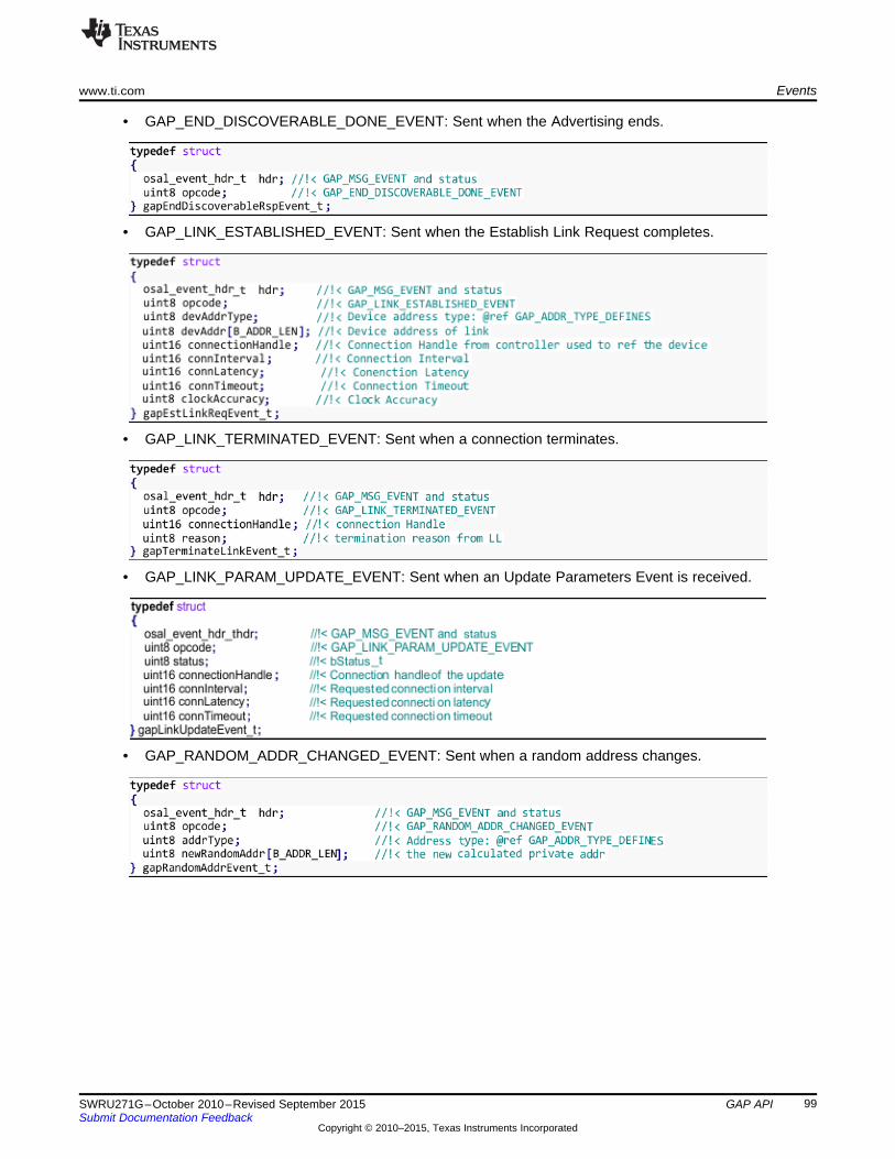
www.ti.com Events
• GAP_END_DISCOVERABLE_DONE_EVENT: Sent when the Advertising ends.
• GAP_LINK_ESTABLISHED_EVENT: Sent when the Establish Link Request completes.
• GAP_LINK_TERMINATED_EVENT: Sent when a connection terminates.
• GAP_LINK_PARAM_UPDATE_EVENT: Sent when an Update Parameters Event is received.
• GAP_RANDOM_ADDR_CHANGED_EVENT: Sent when a random address changes.
99SWRU271G–October 2010–Revised September 2015 GAP APISubmit Documentation Feedback
Copyright © 2010–2015, Texas Instruments Incorporated

Events www.ti.com
• GAP_SIGNATURE_UPDATED_EVENT: Sent when the signature counter of the device updates.
• GAP_AUTHENTICATION_COMPLETE_EVENT: Sent when the Authentication (pairing) processcompletes.
• GAP_PASSKEY_NEEDED_EVENT: Sent when a Passkey is needed. This is part of the pairingprocess.
• GAP_SLAVE_REQUESTED_SECURITY_EVENT: Sent when a Slave Security Request is received.
• GAP_DEVICE_INFO_EVENT: Sent during the Device Discovery Process when a device is discovered.
100 GAP API SWRU271G–October 2010–Revised September 2015Submit Documentation Feedback
Copyright © 2010–2015, Texas Instruments Incorporated

www.ti.com Events
• GAP_BOND_COMPLETE_EVENT: Sent when the bonding process completes.
• GAP_PAIRING_REQ_EVENT: Sent when an unexpected Pairing Request is received.
101SWRU271G–October 2010–Revised September 2015 GAP APISubmit Documentation Feedback
Copyright © 2010–2015, Texas Instruments Incorporated

Appendix BSWRU271G–October 2010–Revised September 2015
GAPRole Peripheral Role API
B.1 Commands
bStatus_t GAPRole_SetParameter(uint16 param, uint8 len, void *pValue)Set a GAP Role parameter.
Parameters param – Profile parameter ID (see Section B.2)
len – length of data to write
pValue – pointer to value to set parameter. This pointer depends on the parameter IDand will be cast to the appropriate data type.
Returns SUCCESS
INVALIDPARAMETER: param was not valid.
bleInvalidRange: len is not valid for the given param.
blePending: previous param update has not been completed
bleIncorrectMode: cannot start connectable advertising because nonconnectableadvertising is enabled
bStatus_t GAPRole_GetParameter(uint16 param, void *pValue)Set a GAP Role parameter.
Parameters param – Profile parameter ID (Section B.2)
pValue – pointer to location to get parameter. This is dependent on the parameter IDand will be cast to the appropriate data type.
Returns SUCCESS
INVALIDPARAMETER: param was not valid
bStatus_t GAPRole_StartDevice(gapRolesCBs_t *pAppCallbacks)Initializes the device as a peripheral and configures the application callbackfunction.
Parameters pAppCallbacks – pointer to application callbacks (Section B.3)
Returns SUCCESS
bleAlreadyInRequestedMode: device was already initialized
bStatus_t GAPRole_TerminateConnection(void)Terminates an existing connection.
Returns SUCCESS: connection termination process has started.
bleIncorrectMode: there is no active connection.
LL_STATUS_ERROR_CTRL_PROC_ALREADY_ACTIVE: disconnect is in progress.
102 GAPRole Peripheral Role API SWRU271G–October 2010–Revised September 2015Submit Documentation Feedback
Copyright © 2010–2015, Texas Instruments Incorporated

www.ti.com Commands
bStatus_t GAPRole_SendUpdateParam(uint16 minConnInterval, uint16 maxConnInterval, uint16latency, uint16 connTimeout, uint8 handleFailure)Update the parameters of an existing connection.
Parameters ConnInterval – the new connection interval
latency – the new slave latency
connTimeout – the new time-out value
handleFailure – what to do if the update does not occur
Available actions:• GAPROLE_NO_ACTION 0 // Take no action upon unsuccessful parameter updates• GAPROLE_RESEND_PARAM_UPDATE 1 // Continue to resend request until
successful update• GAPROLE_TERMINATE_LINK 2 // Terminate link upon unsuccessful parameter
updates.
Returns SUCCESS: parameter update process has started
BleNotConnected: there is no connection so cannot update parameters
103SWRU271G–October 2010–Revised September 2015 GAPRole Peripheral Role APISubmit Documentation Feedback
Copyright © 2010–2015, Texas Instruments Incorporated
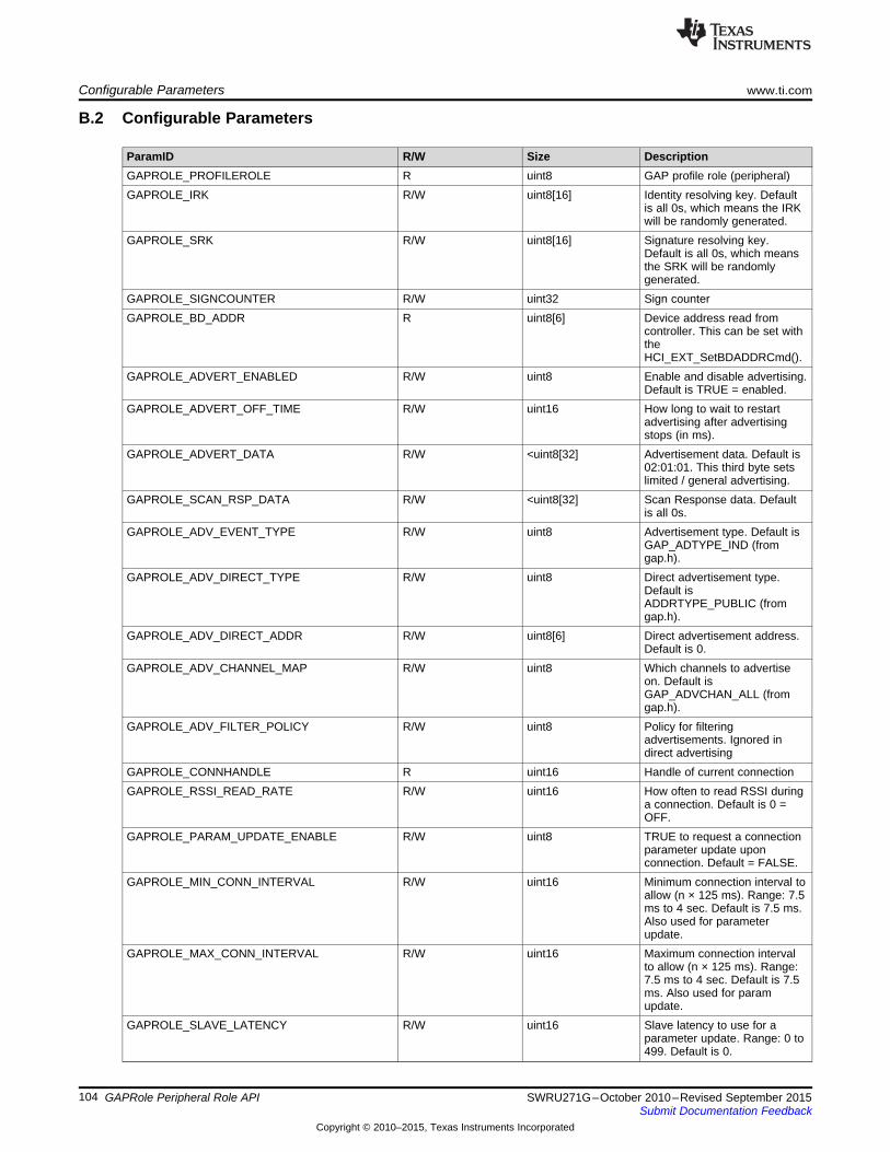
Configurable Parameters www.ti.com
B.2 Configurable Parameters
ParamID R/W Size DescriptionGAPROLE_PROFILEROLE R uint8 GAP profile role (peripheral)GAPROLE_IRK R/W uint8[16] Identity resolving key. Default
is all 0s, which means the IRKwill be randomly generated.
GAPROLE_SRK R/W uint8[16] Signature resolving key.Default is all 0s, which meansthe SRK will be randomlygenerated.
GAPROLE_SIGNCOUNTER R/W uint32 Sign counterGAPROLE_BD_ADDR R uint8[6] Device address read from
controller. This can be set withtheHCI_EXT_SetBDADDRCmd().
GAPROLE_ADVERT_ENABLED R/W uint8 Enable and disable advertising.Default is TRUE = enabled.
GAPROLE_ADVERT_OFF_TIME R/W uint16 How long to wait to restartadvertising after advertisingstops (in ms).
GAPROLE_ADVERT_DATA R/W <uint8[32] Advertisement data. Default is02:01:01. This third byte setslimited / general advertising.
GAPROLE_SCAN_RSP_DATA R/W <uint8[32] Scan Response data. Defaultis all 0s.
GAPROLE_ADV_EVENT_TYPE R/W uint8 Advertisement type. Default isGAP_ADTYPE_IND (fromgap.h).
GAPROLE_ADV_DIRECT_TYPE R/W uint8 Direct advertisement type.Default isADDRTYPE_PUBLIC (fromgap.h).
GAPROLE_ADV_DIRECT_ADDR R/W uint8[6] Direct advertisement address.Default is 0.
GAPROLE_ADV_CHANNEL_MAP R/W uint8 Which channels to advertiseon. Default isGAP_ADVCHAN_ALL (fromgap.h).
GAPROLE_ADV_FILTER_POLICY R/W uint8 Policy for filteringadvertisements. Ignored indirect advertising
GAPROLE_CONNHANDLE R uint16 Handle of current connectionGAPROLE_RSSI_READ_RATE R/W uint16 How often to read RSSI during
a connection. Default is 0 =OFF.
GAPROLE_PARAM_UPDATE_ENABLE R/W uint8 TRUE to request a connectionparameter update uponconnection. Default = FALSE.
GAPROLE_MIN_CONN_INTERVAL R/W uint16 Minimum connection interval toallow (n × 125 ms). Range: 7.5ms to 4 sec. Default is 7.5 ms.Also used for parameterupdate.
GAPROLE_MAX_CONN_INTERVAL R/W uint16 Maximum connection intervalto allow (n × 125 ms). Range:7.5 ms to 4 sec. Default is 7.5ms. Also used for paramupdate.
GAPROLE_SLAVE_LATENCY R/W uint16 Slave latency to use for aparameter update. Range: 0 to499. Default is 0.
104 GAPRole Peripheral Role API SWRU271G–October 2010–Revised September 2015Submit Documentation Feedback
Copyright © 2010–2015, Texas Instruments Incorporated

www.ti.com Callbacks
ParamID R/W Size DescriptionGAPROLE_TIMEOUT_MULTIPLIER R/W uint16 Supervision timeout to use for
a parameter update (n × 10ms). Range: 100 ms to 32 sec.Default is 1000 ms.
GAPROLE_CONN_BD_ADDR R uint8[6] Address of connected device.GAPROLE_CONN_INTERVAL R uint16 Current connection interval.GAPROLE_CONN_LATENCY R uint16 Current slave latency.GAPROLE_CONN_TIMEOUT R uint16 Current supervision timeout.GAPROLE_PARAM_UPDATE_REQ W uint8 Set this to TRUE to send a
parameter update request.GAPROLE_STATE R uint8 Gap peripheral role state
(enumerated ingaprole_States_t inperipheral.h)
B.3 CallbacksThese callbacks are functions whose pointers are passed from the application to the GAPRole so theGAPRole can return events to the application. They are passed as the following:
See the SimpleBLEPeripheral application for an example.
B.3.1 State Change Callback (pfnStateChange)This callback passes the current GAPRole state to the application whenever the state changes. Thisfunction is of the following type:
The GAPRole states (newState) are the following:• GAPROLE_INIT //!< Waiting to be started• GAPROLE_STARTED //!< Started but not advertising• GAPROLE_ADVERTISING_NONCONN //!< Currently using nonconnectable Advertising• GAPROLE_WAITING //!< Device is started but not advertising; it is in waiting period before advertising
again• GAPROLE_WAITING_AFTER_TIMEOUT //!< Device just timed out from a connection but is not yet
advertising; it is in waiting period before advertising again• GAPROLE_CONNECTED //!< In a connection• GAPROLE_CONNECTED_ADV //!< In a connection + advertising• GAPROLE_ERROR //!< Error occurred – invalid state
105SWRU271G–October 2010–Revised September 2015 GAPRole Peripheral Role APISubmit Documentation Feedback
Copyright © 2010–2015, Texas Instruments Incorporated

Callbacks www.ti.com
B.3.2 RSSI Callback (pfnRssiRead)When enabled, this function reports the RSSI to the application at a rate set by theGAPROLE_RSSI_READ_RATE GAPRole parameter. Setting this parameter to 0 disables the RSSIreporting. This function is defined as follows:
This function passes a signed 1-byte value (newRSSI) of the last reported RSSI to the application.
106 GAPRole Peripheral Role API SWRU271G–October 2010–Revised September 2015Submit Documentation Feedback
Copyright © 2010–2015, Texas Instruments Incorporated

Appendix CSWRU271G–October 2010–Revised September 2015
GAPRole Central Role API
C.1 Commands
bStatus_t GAPCentralRole_StartDevice(gapCentralRoleCB_t *pAppCallbacks)Start the device in Central role. This function is typically called once duringsystem startup.
Parameters pAppCallbacks – pointer to application callbacks
Returns SUCCESS
bleAlreadyInRequestedMode: Device already started.
bStatus_t GAPCentralRole_SetParameter(uint16 param, uint8 len, void *pValue)Set a GAP Role parameter.
Parameters param – Profile parameter ID (see Section C.2)
len – length of data to write
pValue – pointer to value to set parameter. This is dependent on the parameter ID and iscast to the appropriate data type.
Returns SUCCESS
INVALIDPARAMETER: param was not valid
bleInvalidRange: len is invalid for the given param
bStatus_t GAPCentralRole_GetParameter (uint16 param, void *pValue)Set a GAP Role parameter.
Parameters param – Profile parameter ID (see Section C.2)
pValue – pointer to buffer to contain the read data
Returns SUCCESS
INVALIDPARAMETER: param was not valid
107SWRU271G–October 2010–Revised September 2015 GAPRole Central Role APISubmit Documentation Feedback
Copyright © 2010–2015, Texas Instruments Incorporated

Commands www.ti.com
bStatus_t GAPCentralRole_TerminateLink (uint16 connHandle);Terminates an existing connection.
Parameters connHandle - connection handle of link to terminate or...
0xFFFE: cancel the current link establishment request or...
0xFFFF: terminate all links
Returns SUCCESS: termination has started
bleIncorrectMode: there is no active connection
LL_STATUS_ERROR_CTRL_PROC_ALREADY_ACTIVE: terminate procedure alreadystarted
bStatus_t GAPCentralRole_EstablishLink(uint8 highDutyCycle, uint8 whiteList, uint8addrTypePeer, uint8 *peerAddr)Establishes a link to a peer device.
Parameters highDutyCycle - TRUE to high duty cycle scan, FALSE if not
whiteList - determines use of the white list
addrTypePeer - address type of the peer device:
peerAddr - peer device address
Returns SUCCESS: link establishment has started
bleIncorrectMode: invalid profile role.
bleNotReady: a scan is in progress.
bleAlreadyInRequestedMode: cannot process now.
bleNoResources: too many links.
108 GAPRole Central Role API SWRU271G–October 2010–Revised September 2015Submit Documentation Feedback
Copyright © 2010–2015, Texas Instruments Incorporated

www.ti.com Commands
bStatus_t GAPCentralRole_UpdateLink(uint16 connHandle, uint16 connIntervalMin, uint16connIntervalMax, uint16 connLatency, uint16 connTimeout)Update the link connection parameters.
Parameters connHandle - connection handle
connIntervalMin - minimum connection interval in 1.25 ms units
connIntervalMax - maximum connection interval in 1.25 ms units
connLatency - number of LL latency connection events
connTimeout - connection timeout in 10 ms units
Returns SUCCESS: parameter update has started
bleNotConnected: No connection to update.
INVALIDPARAMETER: connection parameters are invalid
LL_STATUS_ERROR_ILLEGAL_PARAM_COMBINATION: connection parameters donot meet BLE spec requirements: STO > (1 + Slave Latency) × (Connection Interval × 2)
LL_STATUS_ERROR_INACTIVE_CONNECTION: connHandle is not active
LL_STATUS_ERROR_CTRL_PROC_ALREADY_ACTIVE: there is already a paramupdate in process
LL_STATUS_ERROR_UNACCEPTABLE_CONN_INTERVAL: connection interval wontwork because it is not a multiple or divisor of other simultaneous connection’s intervals,or the connection’s interval is not less than the allowed maximum connection interval asdetermined by the maximum number of connections times the number of slots perconnection
bStatus_t GAPCentralRole_StartDiscovery(uint8 mode, uint8 activeScan, uint8 whiteList)Start a device discovery scan.
Parameters mode - discovery mode
activeScan - TRUE to perform active scan
whiteList - TRUE to only scan for devices in the white list
Returns SUCCESS: device discovery has started
bleAlreadyInRequestedMode: Device discovery already started.
bleMemAllocError: not enough memory to allocate device discovery structure.
LL_STATUS_ERROR_BAD_PARAMETER: bad parameter
LL_STATUS_ERROR_COMMAND_DISALLOWED
109SWRU271G–October 2010–Revised September 2015 GAPRole Central Role APISubmit Documentation Feedback
Copyright © 2010–2015, Texas Instruments Incorporated

Commands www.ti.com
bStatus_t GAPCentralRole_CancelDiscovery(void)Cancel a device discovery scan.
Parameters None
Returns SUCCESS: cancelling of device discovery has started
bleIncorrectMode: Not in discovery mode.
bStatus_t GAPCentralRole_StartRssi(uint16 connHandle, uint16 period)Start periodic RSSI reads on a link.
Parameters connHandle - connection handle of link
period - RSSI read period in ms
Returns SUCCESS: RSSI calculation has started
bleIncorrectMode: No active link.
bleNoResources: No resources for allocation.
bStatus_t GAPCentralRole_CancelRssi(uint16 connHandle)Cancel periodic RSSI reads on a link.
Parameters connHandle - connection handle of link
Returns SUCCESS
bleIncorrectMode: No active link.
110 GAPRole Central Role API SWRU271G–October 2010–Revised September 2015Submit Documentation Feedback
Copyright © 2010–2015, Texas Instruments Incorporated

www.ti.com Configurable Parameters
C.2 Configurable Parameters
ParamID R/W Size DescriptionGAPCENTRALROLE_IRK R/W uint8[16] Identity resolving key. Default
is all 0, which means the IRKare randomly generated.
GAPCENTRALROLE_SRK R/W uint8[16] Signature resolving key.Default is all 0, which meansthe SRK are randomlygenerated.
GAPCENTRALROLE_SIGNCO R/W uint32 Sign counter.UNTERGAPCENTRALROLE_BD_AD R uint8[6] Device address read fromDR controller. This can be set with
theHCI_EXT_SetBDADDRCmd().
GAPCENTRALROLE_MAX_S R/W uint8 Maximum number of discoverCAN_RES scan results to receive. Default
is 8, 0 is unlimited.
C.3 CallbacksThese callbacks are functions whose pointers are passed from the application to the GAPRole so that theGAPRole can return events to the application. They are passed as the following:
See the SimpleBLECentral application for an example.
C.3.1 RSSI Callback (rssiCB)This function reports the RSSI to the application as a result of the GAPCentralRole_StartRssi() command.This function is the following type:
This function passes a signed one byte value (newRSSI) of the last reported RSSI to the application for agiven connection handle (connHandle).
111SWRU271G–October 2010–Revised September 2015 GAPRole Central Role APISubmit Documentation Feedback
Copyright © 2010–2015, Texas Instruments Incorporated

Callbacks www.ti.com
C.3.2 Central Event Callback (eventCB)This callback is used to pass GAP state change events to the application. This callback is the followingtype:
NOTE: TRUE should be returned from this function if the GAPRole is to deallocate the eventmessage. FALSE should be returned if the application deallocates. By default, TRUE isalways returned. If the event message is to be processed by the application at a later time(not just in the callback context), FALSE should be returned
The possible GAPRole central states are in the following list. See Section A.3 for more information onthese events:• GAP_DEVICE_INIT_DONE_EVENT• GAP_DEVICE_DISCOVERY_EVENT• GAP_LINK_ESTABLISHED_EVENT• GAP_LINK_TERMINATED_EVENT• GAP_LINK_PARAM_UPDATE_EVENT• GAP_DEVICE_INFO_EVENT
112 GAPRole Central Role API SWRU271G–October 2010–Revised September 2015Submit Documentation Feedback
Copyright © 2010–2015, Texas Instruments Incorporated

Appendix DSWRU271G–October 2010–Revised September 2015
GATT/ATT API
This section describes the API of the GATT and ATT layers. The sections are combined because theprocedure is to send GATT commands and receive ATT events in Section 5.4.3.1. The return values forthe commands in this section are in Section D.3. The possible return values are similar for thesecommands so refer to Section D.3.
D.1 Server Commands
bStatus_t GATT_Indication( uint16 connHandle, attHandleValueInd_t *pInd, uint8 authenticated,uint8 taskId );Indicates a characteristic value to a client and expect an acknowledgment.Memory must be allocated or freed based on the results of this command. SeeSection 7.6for more information.
Parameters connHandle: connection to use
pInd: pointer to indication to be sent
authenticated: whether an authenticated link is required
taskId: task to be notified of acknowledgment
Corresponding Events If the return status is SUCCESS, the calling application task will receive aGATT_MSG_EVENT message with type ATT_HANDLE_VALUE_CFM upon anacknowledgment. It is only at this point that this subprocedure is considered complete.
bStatus_t GATT_Notification( uint16 connHandle, attHandleValueNoti_t *pNoti, uint8authenticated )Notifies a characteristic value to a client. Note that memory must be allocated /freed based on the results of this command. See Section 7.6 for more information.
Parameters connHandle: connection to use
pNoti: pointer to notification to be sent
authenticated: whether an authenticated link is required
Corresponding Events If the return status is SUCCESS, the notification has been successfully queued fortransmission.
113SWRU271G–October 2010–Revised September 2015 GATT/ATT APISubmit Documentation Feedback
Copyright © 2010–2015, Texas Instruments Incorporated

Client Commands www.ti.com
D.2 Client Commands
bStatus_t GATT_InitClient(void)Initialize the GATT client in the BLE Stack.
Notes GATT clients should call this from the application initialization function.
bStatus_t GATT_RegisterForInd (uint8 taskId)Register to receive incoming ATT Indications or Notifications of attribute values.
Parameters taskId: task which to forward indications or notifications
Notes GATT clients should call this from the application initialization function.
bStatus_t GATT_DiscAllPrimaryServices( uint16 connHandle, uint8 taskId)Used by a client to discover all primary services on a server.
Parameters connHandle: connection to use
taskId: task to be notified of response
Corresponding Events If the return status is SUCCESS, the calling application task receives multipleGATT_MSG_EVENT messages with type ATT_READ_BY_GRP_TYPE_RSP orATT_ERROR_RSP (if an error occurred on the server). This sub-procedure is completewhen either ATT_READ_BY_GRP_TYPE_RSP (with bleProcedureComplete orbleTimeout status) or the calling application task receives the ATT_ERROR_RSP (withSUCCESS status).
bStatus_t GATT_DiscPrimaryServiceByUUID( uint16 connHandle, uint8 *pValue, uint8 len, uint8taskId )Used by a client to discover a specific primary service on a server when only theService UUID is known.
Parameters connHandle: connection to use
pValue: pointer to value (UUID) to look for
len: length of value
taskId: task to be notified of response
Corresponding Events If the return status is SUCCESS, the calling application task receives multipleGATT_MSG_EVENT messages with type ATT_FIND_BY_TYPE_VALUE_RSP orATT_ERROR_RSP (if an error occurred on the server). This sub-procedure is completewhen either ATT_FIND_BY_TYPE_VALUE_RSP (with bleProcedureComplete orbleTimeout status) or the calling application task receives the ATT_ERROR_RSP (withSUCCESS status).
114 GATT/ATT API SWRU271G–October 2010–Revised September 2015Submit Documentation Feedback
Copyright © 2010–2015, Texas Instruments Incorporated

www.ti.com Client Commands
bStatus_t GATT_FindIncludedServices( uint16 connHandle, uint16 startHandle, uint16endHandle, uint8 taskId )Used by a client to find included services with a primary service definition on aserver.
Parameters connHandle: connection to use
startHandle: start handle of primary service to search
endHandle: end handle of primary service to search
taskId: task to be notified of response
Corresponding Events If the return status is SUCCESS, the calling application task receives multipleGATT_MSG_EVENT messages with type ATT_READ_BY_TYPE_RSP orATT_ERROR_RSP (if an error occurred on the server). This subprocedure is completewhen either ATT_READ_BY_TYPE_RSP (with bleProcedureComplete or bleTimeoutstatus) or ATT_ERROR_RSP (with SUCCESS status) is received by the callingapplication task. If the return status is SUCCESS, the calling application task receivesmultiple GATT_MSG_EVENT messages with type ATT_FIND_BY_TYPE_VALUE_RSPor ATT_ERROR_RSP (if an error occurred on the server). This sub-procedure iscomplete when either ATT_FIND_BY_TYPE_VALUE_RSP (with bleProcedureCompleteor bleTimeout status) or the calling application task recieves the ATT_ERROR_RSP(with SUCCESS status).
bStatus_t GAPRole_GetParameter(uint16 param, void *pValue)Get a GAP Role parameter.
Parameters param – Profile parameter ID (See Section F.2)
pValue – pointer to a location to get the value. This pointer depends on the param IDand is cast to the appropriate data type.
Returns SUCCESS
INVALIDPARAMETER: param was not valid
bStatus_t GATT_DiscAllChars( uint16 connHandle, uint16 startHandle, uint16 endHandle, uint8taskId )Used by a client to find all the characteristic declarations within a service whenthe handle range of the service is known.
Parameters connHandle: connection to use
startHandle: start handle of service to search
endHandle: end handle of service to search
taskId: task to be notified of response
Corresponding Events If the return status is SUCCESS, the calling application task receives multipleGATT_MSG_EVENT messages with type ATT_READ_BY_TYPE_RSP orATT_ERROR_RSP (if an error occurred on the server). This sub-procedure is completewhen either ATT_READ_BY_TYPE_RSP (with bleProcedureComplete or bleTimeoutstatus) or the calling application task receives the ATT_ERROR_RSP (with SUCCESSstatus).
115SWRU271G–October 2010–Revised September 2015 GATT/ATT APISubmit Documentation Feedback
Copyright © 2010–2015, Texas Instruments Incorporated

Client Commands www.ti.com
bStatus_t GATT_DiscCharsByUUID( uint16 connHandle, attReadByTypeReq_t *pReq, uint8taskId )Used by a client to discover service characteristics on a server when the servicehandle range and characteristic UUID is known.
Parameters connHandle: connection to use
pReq: pointer to request to be sent, including start and end handles of service and UUIDof characteristic value for which to search.
taskId: task to be notified of response
Corresponding Events If the return status is SUCCESS, the calling application task receives multipleGATT_MSG_EVENT messages with type ATT_READ_BY_TYPE_RSP orATT_ERROR_RSP (if an error occurred on the server). This sub-procedure is completewhen either ATT_READ_BY_TYPE_RSP (with bleProcedureComplete or bleTimeoutstatus) orthe calling application task recieves the ATT_ERROR_RSP (with SUCCESSstatus).
bStatus_t GATT_DiscAllCharDescs ( uint16 connHandle, uint16 startHandle, uint16 endHandle,uint8 taskId )Used by a client to find all the characteristic descriptor’s Attribute Handles andAttributeTypes within a characteristic definition when only the characteristichandle range is known.
Parameters connHandle: connection to use
startHandle: start handle
endHandle: end handle
taskId: task to be notified of response
Notes If the return status is SUCCESS, the calling application task receives multipleGATT_MSG_EVENT messages with type ATT_FIND_INFO_RSP or ATT_ERROR_RSP(if an error occurred on the server). This sub-procedure is complete when eitherATT_FIND_INFO_RSP (with bleProcedureComplete or bleTimeout status) or the callingapplication task receives the ATT_ERROR_RSP (with SUCCESS status).
bStatus_t GATT_ReadCharValue ( uint16 connHandle, attReadReq_t *pReq, uint8 taskId )Used to read a Characteristic Value from a server when the client knows theCharacteristic Value Handle.
Parameters connHandle: connection to use
pReq: pointer to request to be sent
taskId: task to be notified of response
Notes If the return status is SUCCESS, the calling application task receives an OSALGATT_MSG_EVENT message with type ATT_READ_RSP or ATT_ERROR_RSP (if anerror occurred on the server). This sub- procedure is complete when eitherATT_READ_RSP (with SUCCESS or bleTimeout status) or the calling applicationreceives the ATT_ERROR_RSP (with SUCCESS status).
116 GATT/ATT API SWRU271G–October 2010–Revised September 2015Submit Documentation Feedback
Copyright © 2010–2015, Texas Instruments Incorporated

www.ti.com Client Commands
bStatus_t GATT_ReadUsingCharUUID ( uint16 connHandle, attReadByTypeReq_t *pReq, uint8taskId )Used to read a Characteristic Value from a server when the client only knows thecharacteristic UUID and does not know the handle of the characteristic.
Parameters connHandle: connection to use
pReq: pointer to request to be sent
taskId: task to be notified of response
Notes If the return status is SUCCESS, the calling application task receives an OSALGATT_MSG_EVENT message with type ATT_READ_BY_TYPE_RSP orATT_ERROR_RSP (if an error occurred on the server). This sub-procedure is completewhen either ATT_READ_BY_TYPE_RSP (with SUCCESS or bleTimeout status) or thecalling application task receives the ATT_ERROR_RSP (with SUCCESS status).
bStatus_t GATT_ReadLongCharValue ( uint16 connHandle, attReadBlobReq_t *pReq, uint8taskId )Used to read a Characteristic Value from a server when the client knows theCharacteristic Value Handle and the length of the Characteristic Value is longerthan can be sent in a single Read Response Attribute Protocol message.
Parameters connHandle: connection to use
pReq: pointer to request to be sent
taskId: task to be notified of response
Notes If the return status is SUCCESS, the calling application task receives multipleGATT_MSG_EVENT messages with type ATT_READ_BLOB_RSP orATT_ERROR_RSP (if an error occurred on the server). This sub-procedure is completewhen either ATT_READ_BLOB_RSP (with bleProcedureComplete or bleTimeout status)or the calling application task receives the ATT_ERROR_RSP (with SUCCESS status).
bStatus_t GATT_ReadMultiCharValues ( uint16 connHandle, attReadMultiReq_t *pReq, uint8taskId )Used to read multiple Characteristic Values from a server when the client knowsthe Characteristic Value Handles.
Parameters connHandle: connection to use
pReq: pointer to request to be sent
taskId: task to be notified of response
Notes If the return status from this function is SUCCESS, the calling application task receivesan OSAL GATT_MSG_EVENT message with type ATT_READ_MULTI_RSP orATT_ERROR_RSP (if an error occurred on the server). This sub-procedure is completewhen either ATT_READ_MULTI_RSP (with SUCCESS or bleTimeout status) or thecalling application task receives the ATT_ERROR_RSP (with SUCCESS status).
bStatus_t GATT_WriteNoRsp (uint16 connHandle, attWriteReq_t *pReq)Used to request the server to write or cancel the write of all the prepared valuescurrently held in the prepare queue from this client.
Parameters connHandle: connection to use
pReq: pointer to command to be sent
117SWRU271G–October 2010–Revised September 2015 GATT/ATT APISubmit Documentation Feedback
Copyright © 2010–2015, Texas Instruments Incorporated

Client Commands www.ti.com
Notes No response will be sent to the calling application task for this sub-procedure. If theCharacteristic Value write request is the wrong size or has an invalid value as defined bythe profile, the write fails and the server generates no error.
bStatus_t GATT_SignedWriteNoRsp (uint16 connHandle, attWriteReq_t *pReq)Used to write a Characteristic Value to a server when the client knows theCharacteristic Value Handle and the ATT Bearer is not encrypted. This sub-procedure shall only be used if the Characteristic Properties authenticated bit isenabled and the client and server device share a bond as defined in the GAP.
Parameters connHandle: connection to use
pReq: pointer to command to be sent
Notes No response is sent to the calling application task for this sub-procedure. If theauthenticated Characteristic Value is the wrong size or has an invalid value as definedby the profile or the signed value fails to authenticate the client, the write fails and noerror is generated by the server.
bStatus_t GATT_WriteCharValue ( uint16 connHandle, attWriteReq_t *pReq, uint8 taskId )Used to write a characteristic value to a server when the client knows thecharacteristic value handle.
Parameters connHandle: connection to use
pReq: pointer to request to be sent
taskId: task to be notified of response
Notes If the return status from this function is SUCCESS, the calling application task receivesan OSAL GATT_MSG_EVENT message with type ATT_WRITE_RSP orATT_ERROR_RSP (if an error occurred on the server). This sub-procedure is completewhen either ATT_WRITE_RSP (with SUCCESS or bleTimeout status) or the callingapplication task receives the ATT_ERROR_RSP (with SUCCESS status).
bStatus_t GATT_ReliableWrites ( uint16 connHandle, attPrepareWriteReq_t *pReq, uint8numReqs, uint8 flags, uint8 taskId )Used to write a Characteristic Value to a server when the client knows theCharacteristic Value Handle, and assurance is required that the correctCharacteristic Value is going to be written by transferring the Characteristic Valueto be written in both directions before the write is performed.
Parameters connHandle: connection to use
pReq: pointer to requests to be sent (must be allocated)
numReqs - number of requests in pReq
flags - execute write request flags
taskId: task to be notified of response
Notes If the return status is SUCCESS, the calling application task receives multipleGATT_MSG_EVENT messages with type ATT_PREPARE_WRITE_RSP,ATT_EXECUTE_WRITE_RSP or ATT_ERROR_RSP (if an error occurred on theserver). This sub-procedure is complete when either ATT_PREPARE_WRITE_RSP (withbleTimeout status), ATT_EXECUTE_WRITE_RSP (with SUCCESS or bleTimeoutstatus), or the calling application task receives the ATT_ERROR_RSP (with SUCCESSstatus) .
118 GATT/ATT API SWRU271G–October 2010–Revised September 2015Submit Documentation Feedback
Copyright © 2010–2015, Texas Instruments Incorporated
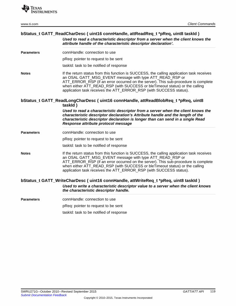
www.ti.com Client Commands
bStatus_t GATT_ReadCharDesc ( uint16 connHandle, attReadReq_t *pReq, uint8 taskId )Used to read a characteristic descriptor from a server when the client knows theattribute handle of the characteristic descriptor declaration’.
Parameters connHandle: connection to use
pReq: pointer to request to be sent
taskId: task to be notified of response
Notes If the return status from this function is SUCCESS, the calling application task receivesan OSAL GATT_MSG_EVENT message with type ATT_READ_RSP orATT_ERROR_RSP (if an error occurred on the server). This sub-procedure is completewhen either ATT_READ_RSP (with SUCCESS or bleTimeout status) or the callingapplication task receives the ATT_ERROR_RSP (with SUCCESS status).
bStatus_t GATT_ReadLongCharDesc ( uint16 connHandle, attReadBlobReq_t *pReq, uint8taskId )Used to read a characteristic descriptor from a server when the client knows thecharacteristic descriptor declaration’s Attribute handle and the length of thecharacteristic descriptor declaration is longer than can send in a single ReadResponse attribute protocol message
Parameters connHandle: connection to use
pReq: pointer to request to be sent
taskId: task to be notified of response
Notes If the return status from this function is SUCCESS, the calling application task receivesan OSAL GATT_MSG_EVENT message with type ATT_READ_RSP orATT_ERROR_RSP (if an error occurred on the server). This sub-procedure is completewhen either ATT_READ_RSP (with SUCCESS or bleTimeout status) or the callingapplication task receives the ATT_ERROR_RSP (with SUCCESS status).
bStatus_t GATT_WriteCharDesc ( uint16 connHandle, attWriteReq_t *pReq, uint8 taskId )Used to write a characteristic descriptor value to a server when the client knowsthe characteristic descriptor handle.
Parameters connHandle: connection to use
pReq: pointer to request to be sent
taskId: task to be notified of response
119SWRU271G–October 2010–Revised September 2015 GATT/ATT APISubmit Documentation Feedback
Copyright © 2010–2015, Texas Instruments Incorporated

Return Values www.ti.com
bStatus_t GATT_WriteLongCharDesc ( uint16 connHandle, gattPrepareWriteReq_t *pReq, uint8taskId )Used to write a Characteristic Value to a server when the client knows theCharacteristic Value Handle but the length of the Characteristic Value is longerthan can be sent in a single Write Request Attribute Protocol message.
Parameters connHandle: connection to use
pReq: pointer to request to be sent
taskId: task to be notified of response
Notes If the return status is SUCCESS, the calling application task receives multipleGATT_MSG_EVENT messages with type ATT_PREPARE_WRITE_RSP,ATT_EXECUTE_WRITE_RSP or ATT_ERROR_RSP (if an error occurred on theserver). This sub-procedure is complete when either ATT_PREPARE_WRITE_RSP (withbleTimeout status), ATT_EXECUTE_WRITE_RSP (with SUCCESS or bleTimeoutstatus), or the calling application task recieves the ATT_ERROR_RSP (with SUCCESSstatus).
D.3 Return Values• SUCCESS (0x00): Command was executed as expected. See the command API for corresponding
events to expect.• INVALIDPARAMETER (0x02): Invalid connection handle or request field• ATT_ERR_INSUFFICIENT_AUTHEN (0x05): The attribute requires authentication• ATT_ERR_INSUFFICIENT_KEY_SIZE (0x0C): The key size for encrypting is insufficient• ATT_ERR_INSUFFICIENT_ENCRYPT (0x0F): The attribute requires encryption• MSG_BUFFER_NOT_AVAIL (0x04): An HCI buffer is unavailable. Retry later.• bleNotConnected (0x14): The device is unconnected.• blePending (0x17):
– When returned to a client function, a response is pending with the server or the GATT sub-procedure is in progress.
– When returned to server function, confirmation from a client is pending.• bleTimeout (0x16): The previous transaction timed out. No ATT or GATT messages can send until
reconnected.• bleMemAllocError (0x13): A memory allocation error occurred• bleLinkEncrypted (0x19): The link is encrypted. Do not send an attribute PDU includes an
authentication signature on an encrypted link
120 GATT/ATT API SWRU271G–October 2010–Revised September 2015Submit Documentation Feedback
Copyright © 2010–2015, Texas Instruments Incorporated

www.ti.com Events
D.4 EventsEvents are received from the BLE stack in the application as a GATT_MSG_EVENT stack message sentas an OSAL message. The events are received as the following structure, where the method signifies theATT event and the message is a union of the ATT events:
This section lists the ATT events by their method and display their structure that is used in the messagepayload. These events are in the att.h file.• ATT_ERROR_RSP (0x01)
• ATT_FIND_INFO_RSP (0x03)
• ATT_FIND_BY_TYPE_VALUE_RSP (0x07)
• ATT_READ_BY_TYPE_RSP (0x09)
• ATT_READ_RSP (0x0B)
• ATT_READ_BLOB_RSP (0x0D)
121SWRU271G–October 2010–Revised September 2015 GATT/ATT APISubmit Documentation Feedback
Copyright © 2010–2015, Texas Instruments Incorporated

Events www.ti.com
• ATT_READ_MULTI_RSP (0x0F)
• ATT_READ_BY_GRP_TYPE_RSP (0x11)
• ATT_WRITE_RSP (0x13)• ATT_PREPARE_WRITE_RSP (0x17)
• ATT_EXECUTE_WRITE_RSP (0x19)• ATT_HANDLE_VALUE_NOTI (0x1B)
• ATT_HANDLE_VALUE_IND (0x1D)
• ATT_HANDLE_VALUE_CFM (0x1E)– Empty msg field
122 GATT/ATT API SWRU271G–October 2010–Revised September 2015Submit Documentation Feedback
Copyright © 2010–2015, Texas Instruments Incorporated

www.ti.com GATT Commands and Corresponding ATT Events
D.5 GATT Commands and Corresponding ATT EventsThis table lists the possible commands that may cause an event.
ATT Response Events GATT API CallsATT_EXCHANGE_MTU_RSP GATT_ExchangeMTUATT_FIND_INFO_RSP GATT_DiscAllCharDescs,
GATT_DiscAllCharDescsATT_FIND_BY_TYPE_VALUE_RSP GATT_DiscPrimaryServiceByUUIDATT_READ_BY_TYPE_RSP GATT_PrepareWriteReq,
GATT_ExecuteWriteReq,GATT_FindIncludedServices,GATT_DiscAllChars,GATT_DiscCharsByUUID,GATT_ReadUsingCharUUID,
ATT_READ_RSP GATT_ReadCharValue,GATT_ReadCharDesc
ATT_READ_BLOB_RSP GATT_ReadLongCharValue,GATT_ReadLongCharDesc
ATT_READ_MULTI_RSP GATT_ReadMultiCharValuesATT_READ_BY_GRP_TYPE_RSP GATT_DiscAllPrimaryServicesATT_WRITE_RSP GATT_WriteCharValue,
GATT_WriteCharDescATT_PREPARE_WRITE_RSP GATT_WriteLongCharValue,
GATT_ReliableWrites,GATT_WriteLongCharDesc
ATT_EXECUTE_WRITE_RSP GATT_WriteLongCharValue,GATT_ReliableWrites,GATT_WriteLongCharDesc
D.6 ATT_ERROR_RSP Error CodesThis section lists the error codes that can exist in the ATT_ERROR_RSP event and their possible causes.• ATT_ERR_INVALID_HANDLE (0x01): Attribute handle value given was not valid on this attribute
server.• ATT_ERR_READ_NOT_PERMITTED (0x02): Attribute cannot be read.• ATT_ERR_WRITE_NOT_PERMITTED (0x03): Attribute cannot be written.• ATT_ERR_INVALID_PDU (0x04): The attribute PDU was invalid.• ATT_ERR_INSUFFICIENT_AUTHEN (0x05): The attribute requires authentication before it can be
read or written.• ATT_ERR_UNSUPPORTED_REQ (0x06): Attribute server doesn't support the request received from
the attribute client.• ATT_ERR_INVALID_OFFSET (0x07): Offset specified was past the end of the attribute.• ATT_ERR_INSUFFICIENT_AUTHOR (0x08): The attribute requires an authorization before it can be
read or written.• ATT_ERR_PREPARE_QUEUE_FULL (0x09): Too many prepare writes have been queued.• ATT_ERR_ATTR_NOT_FOUND (0x0A): No attribute found within the given attribute handle range.• ATT_ERR_ATTR_NOT_LONG (0x0B): Attribute cannot be read or written using the read blob request
or prepare write request.• ATT_ERR_INSUFFICIENT_KEY_SIZE (0x0C): The encryption key size for encrypting this link is
insufficient.• ATT_ERR_INVALID_VALUE_SIZE (0x0D): The attribute value length is invalid for the operation.• ATT_ERR_UNLIKELY (0x0E): The attribute request requested has encountered an error that was
unlikely and failed to complete as requested.
123SWRU271G–October 2010–Revised September 2015 GATT/ATT APISubmit Documentation Feedback
Copyright © 2010–2015, Texas Instruments Incorporated

ATT_ERROR_RSP Error Codes www.ti.com
• ATT_ERR_INSUFFICIENT_ENCRYPT (0x0F): The attribute requires encryption before it can be reador written.
• ATT_ERR_UNSUPPORTED_GRP_TYPE (0x10): The attribute type is not a supported groupingattribute as defined by a higher layer specification.
• ATT_ERR_INSUFFICIENT_RESOURCES (0x11): Insufficient resources exist to complete the request.
124 GATT/ATT API SWRU271G–October 2010–Revised September 2015Submit Documentation Feedback
Copyright © 2010–2015, Texas Instruments Incorporated

Appendix ESWRU271G–October 2010–Revised September 2015
GATTServApp API
This section details the API of the GATTServApp in gattservapp_util.c.
NOTE: These API are only the public commands that should be called by the profile and/orapplication.
E.1 Commands
void GATTServApp_InitCharCfg( uint16 connHandle, gattCharCfg_t *charCfgTbl )Initialize the client characteristic configuration table for a given connection. Usethis whenever a service is added to the application (see Section 5.4.4.2.2)
Parameters connHandle – connection handle (0xFFFF for all connections).
charCfgTbl – client characteristic configuration table where this characteristic is
bStatus_t GATTServApp_ProcessCharCfg( gattCharCfg_t *charCfgTbl, uint8 *pValue,uint8authenticated, gattAttribute_t *attrTbl, uint16 numAttrs, uint8 taskId,pfnGATTReadAttrCB_t pfnReadAttrCB )Process Client Characteristic Configuration change.
Parameters charCfgTbl – profile characteristic configuration table
pValue – pointer to attribute value.
authenticated – whether an authenticated link is required
attrTbl – whether attribute table.
numAttrs – number of attributes in attribute table.
tasked – task to be notified of confirmation.
pfnReadAttrCB – read callback function pointer.
Returns SUCCESS: parameter was set
INVALIDPARAMETER: one of the parameters was a null pointer
ATT_ERR_INSUFFICIENT_AUTHOR: permissions require authorization
bleTimeout: ATT timeout occurred
blePending: another ATT request is pending
LINKDB_ERR_INSUFFICIENT_AUTHEN: authentication is required but link is notauthenticated
bleMemAllocError: memory allocation failure occurred when allocating buffer
125SWRU271G–October 2010–Revised September 2015 GATTServApp APISubmit Documentation Feedback
Copyright © 2010–2015, Texas Instruments Incorporated

Commands www.ti.com
gattAttribute_t *GATTServApp_FindAttr( gattAttribute_t *pAttrTbl, uint16 numAttrs, uint8*pValue )Find the attribute record within a service attribute table for a given attribute valuepointer.
Parameters pAttrTbl – pointer to attribute table
numAttrs – number of attributes in attribute table
pValue – pointer to attribute value
Returns Pointer to attribute record if found.
NULL, if not found.
bStatus_t GATTServApp_ProcessCCCWriteReq( uint16 connHandle, gattAttribute_t *pAttr, uint8*pValue, uint8 len, uint16 offset, uint16 validCfg )Process the client characteristic configuration write request for a given client.
Parameters connHandle– connection message was received on.
pAttr – pointer to attribute value.
pValue– pointer to data to be written
len – length of data
offset– offset of the first octet to be written
validCfg– valid configuration
Returns SUCCESS: CCC was written correctly
ATT_ERR_INVALID_VALUE: not a valid value for a CCC
ATT_ERR_INVALID_VALUE_SIZE: not a valid size for a CCC
ATT_ERR_ATTR_NOT_LONG: offset needs to be 0
ATT_ERR_INSUFFICIENT_RESOURCES: CCC not found
126 GATTServApp API SWRU271G–October 2010–Revised September 2015Submit Documentation Feedback
Copyright © 2010–2015, Texas Instruments Incorporated
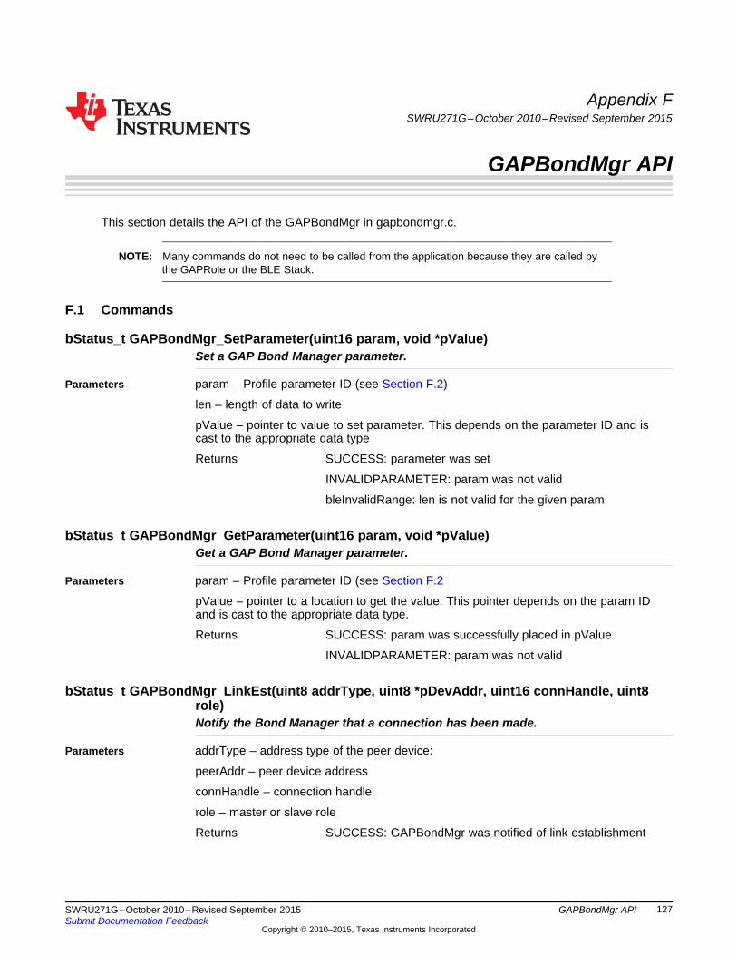
Appendix FSWRU271G–October 2010–Revised September 2015
GAPBondMgr API
This section details the API of the GAPBondMgr in gapbondmgr.c.
NOTE: Many commands do not need to be called from the application because they are called bythe GAPRole or the BLE Stack.
F.1 Commands
bStatus_t GAPBondMgr_SetParameter(uint16 param, void *pValue)Set a GAP Bond Manager parameter.
Parameters param – Profile parameter ID (see Section F.2)
len – length of data to write
pValue – pointer to value to set parameter. This depends on the parameter ID and iscast to the appropriate data type
Returns SUCCESS: parameter was set
INVALIDPARAMETER: param was not valid
bleInvalidRange: len is not valid for the given param
bStatus_t GAPBondMgr_GetParameter(uint16 param, void *pValue)Get a GAP Bond Manager parameter.
Parameters param – Profile parameter ID (see Section F.2
pValue – pointer to a location to get the value. This pointer depends on the param IDand is cast to the appropriate data type.
Returns SUCCESS: param was successfully placed in pValue
INVALIDPARAMETER: param was not valid
bStatus_t GAPBondMgr_LinkEst(uint8 addrType, uint8 *pDevAddr, uint16 connHandle, uint8role)Notify the Bond Manager that a connection has been made.
Parameters addrType – address type of the peer device:
peerAddr – peer device address
connHandle – connection handle
role – master or slave role
Returns SUCCESS: GAPBondMgr was notified of link establishment
127SWRU271G–October 2010–Revised September 2015 GAPBondMgr APISubmit Documentation Feedback
Copyright © 2010–2015, Texas Instruments Incorporated

Commands www.ti.com
void GAPBondMgr_LinkTerm(uint16 connHandle)Notify the Bond Manager that a connection has been terminated.
Parameters connHandle – connection handle
void GAPBondMgr_SlaveReqSecurity(uint16 connHandle)Notify the Bond Manager that a Slave Security Request is received.
Parameters connHandle – connection handle
uint8 GAPBondMgr_ResolveAddr(uint8 addrType, uint8 *pDevAddr, uint8 *pResolvedAddr)Resolve an address from bonding information.
Parameters addrType – address type of the peer device:
peerAddr – peer device address
pResolvedAddr – pointer to buffer to put the resolved address
Returns Bonding index (0 – (GAP_BONDINGS_MAX-1): if address was found...
GAP_BONDINGS_MAX: if address was not found
bStatus_t GAPBondMgr_ServiceChangeInd(uint16 connectionHandle, uint8 setParam )Set/clear the service change indication in a bond record.
Parameters connHandle – connection handle of the connected device or 0xFFFF for devices indatabase.
setParam – TRUE to set the service change indication, FALSE to clear it.
Returns SUCCESS – bond record found and changed
bleNoResources – no bond records found (for 0xFFFF connHandle)
bleNotConnected – connection with connHandle is invalid
bStatus_t GAPBondMgr_UpdateCharCfg(uint16 connectionHandle, uint16 attrHandle, uint16value )Update the Characteristic Configuration in a bond record.
Parameters connectionHandle – connection handle of the connected device or 0xFFFF for alldevices in database.
attrHandle – attribute handle
value – characteristic configuration value
Returns SUCCESS – bond record found and changed
bleNoResources – no bond records found (for 0xFFFF connectionHandle)
bleNotConnected – connection with connectionHandle is invalid
void GAPBondMgr_Register(gapBondCBs_t *pCB)Register callback functions with the bond manager.
Parameters pCB – pointer to callback function structure (see Section F.3)
128 GAPBondMgr API SWRU271G–October 2010–Revised September 2015Submit Documentation Feedback
Copyright © 2010–2015, Texas Instruments Incorporated

www.ti.com Commands
bStatus_t GAPBondMgr_PasscodeRsp(uint16 connectionHandle, uint8 status, uint32 passcode)
Respond to a passcode request and update the passcode if possible.
Parameters connectionHandle – connection handle of the connected device or 0xFFFF for alldevices in database.
status – SUCCESS if passcode is available, otherwise seeSMP_PAIRING_FAILED_DEFINES in gapbondmgr.h
passcode – integer value containing the passcode
Returns SUCCESS: connection found and passcode was changed
bleIncorrectMode: connectionHandle connection not found or pairing has not started
INVALIDPARAMETER: passcode is out of range
bleMemAllocError: heap is out of memory
uint8 GAPBondMgr_ProcessGAPMsg(gapEventHdr_t *pMsg)This is a bypass mechanism to let the bond manager process GAP messages.
Note
NOTE: This bypass mechanism is an advanced feature and should not be calledunless the normal GAP Bond Manager task ID registration is overridden.
Parameters pMsg – GAP event message
Returns TRUE: safe to deallocate incoming GAP message
FALSE: not safe to deallocate an incoming gap message
uint8 GAPBondMgr_CheckNVLen(uint8 id, uint8 len )This function will check the length of a Bond Manager NV Item.
Parameters id – NV ID
len – lengths in bytes of item.
Returns SUCCESS: NV item is the correct length
FAILURE: NV item is an incorrect length
129SWRU271G–October 2010–Revised September 2015 GAPBondMgr APISubmit Documentation Feedback
Copyright © 2010–2015, Texas Instruments Incorporated

Configurable Parameters www.ti.com
F.2 Configurable Parameters
ParamID R/W Size DescriptionGAPBOND_PAIRING_MODE R/W uint8 Default is
GAPBOND_PAIRING_MODE_WAIT_FOR_REQ
GAPBOND_INITIATE_WAIT R/W uint16 Pairing Mode Initiate wait timeout. The time itwill wait for a Pairing Request before sendingthe Slave Initiate Request. Default is 1000 (inmilliseconds)
GAPBOND_MITM_PROTECTION R/W uint8 Man-In-The-Middle (MITM) basically turns onpasskey protection in the pairing algorithm.Default is 0 (disabled).
GAPBOND_IO_CAPABILITIES R/W uint8 Default isGAPBOND_IO_CAP_DISPLAY_ONLY
GAPBOND_OOB_ENABLED R/W uint8 OOB data available for pairing algorithm.Default is 0 (disabled).
GAPBOND_OOB_DATA R/W uint8[16] OOB Data. Default is 0s.GAPBOND_BONDING_ENABLED R/W uint8 Request Bonding during the pairing process
if enabled. Default is 0(disabled).GAPBOND_KEY_DIST_LIST uint8 The key distribution list for bonding. Default
is sEncKey, sIdKey, mIdKey, mSign enabled.GAPBOND_DEFAULT_PASSCODE uint32 The default passcode for MITM protection.
Range is 0 to SWRU2718752999,999.Default is 0.
GAPBOND_ERASE_ALLBONDS W None Erase all of the bonded devices.GAPBOND_KEYSIZE R/W uint8 Key Size used in pairing. Default is 16.GAPBOND_AUTO_SYNC_WL R/W uint8 Clears the White List adds to it each unique
address stored by bonds in NV. Default isFALSE.
GAPBOND_BOND_COUNT R uint8 Gets the total number of bonds stored in NV.Default is 0 (no bonds).
GAPBOND_BOND_FAIL_ACTION W uint8 Possible actions: Central may take upon anunsuccessful bonding. Default is 0x02(Terminate link when a bonding isunsuccessful).
GAPBOND_ERASE_SINGLEBOND W uint8[9] Erase a single bonded device. Must provideaddress type followed by device address.
130 GAPBondMgr API SWRU271G–October 2010–Revised September 2015Submit Documentation Feedback
Copyright © 2010–2015, Texas Instruments Incorporated

www.ti.com Callbacks
F.3 CallbacksThese callbacks are functions whose pointers are passed from the application to the GAPBondMgr so itcan return events to the application. The callbacks are passed as the following structure:
F.3.1 Passcode Callback (passcodeCB)This callback returns to the application the peer device information when a passcode is requested by thepeer device during the paring process. This function is defined as the following:
Based on the parameters passed to this callback like the pairing interface inputs and outputs, theapplication displays the passcode or initiates the entrance of a passcode.
F.3.2 Pairing State Callback (pairStateCB)This callback returns the current pairing state to the application whenever the state changes and thecurrent status of the pairing or bonding process associated with the current state and provides the currentstatus of the pairing. This function is defined as the following:
131SWRU271G–October 2010–Revised September 2015 GAPBondMgr APISubmit Documentation Feedback
Copyright © 2010–2015, Texas Instruments Incorporated

Callbacks www.ti.com
The pairing state(s) is enumerated as the following:• GAPBOND_PAIRING_STATE_STARTED
– The following status is possible for this state:• SUCCESS (0x00): pairing has been initiated
• GAPBOND_PAIRING_STATE_COMPLETE– The following statuses are possible for this state:
• SUCCESS (0x00): pairing is complete. Session keys have been exchanged.• SMP_PAIRING_FAILED_PASSKEY_ENTRY_FAILED (0x01): input failed• SMP_PAIRING_FAILED_OOB_NOT_AVAIL (0x02): Out-of-band data unavailable• SMP_PAIRING_FAILED_AUTH_REQ (0x03): input and output capabilities of devices fails to
authenticate• SMP_PAIRING_FAILED_CONFIRM_VALUE (0x04): the confirm value fails to match the
calculated compare value• SMP_PAIRING_FAILED_NOT_SUPPORTED (0x05): pairing is not supported• SMP_PAIRING_FAILED_ENC_KEY_SIZE (0x06): encryption key size is insufficient• SMP_PAIRING_FAILED_CMD_NOT_SUPPORTED (0x07): The SMP command received is
unsupported on this device• SMP_PAIRING_FAILED_UNSPECIFIED (0x08): encryption failed to start• bleTimeout (0x17): pairing failed to complete before timeout• bleGAPBondRejected (0x32): keys did not match
• GAPBOND_PAIRING_STATE_BONDED– The following statuses are possible for this state:
• LL_ENC_KEY_REQ_REJECTED (0x06): encryption key is missing• LL_ENC_KEY_REQ_UNSUPPORTED_FEATURE (0x1A): feature is unsupported by the remote
device• LL_CTRL_PKT_TIMEOUT_TERM (0x22): Timeout waiting for response• bleGAPBondRejected (0x32): This status is received due to one of the above three errors.
132 GAPBondMgr API SWRU271G–October 2010–Revised September 2015Submit Documentation Feedback
Copyright © 2010–2015, Texas Instruments Incorporated

Appendix GSWRU271G–October 2010–Revised September 2015
HCI Extension API
This section describes the vendor specific HCI Extension API. These proprietary commands are specific tothe CC254x device. Where more detail is required, an example is provided.
NOTE: Unless stated otherwise, the return values for these commands is SUCCESS. This valuedoes not indicate successful completion of the command. These commands result incorresponding events that you should check by the calling application
G.1 Commands
hciStatus_t HCI_EXT_AdvEventNoticeCmd ( uint8 taskID, uint16 taskEvent )This command configures the device to set an event in the user task after eachadvertisement event completes. A non-zero taskEvent value is enable, while a zerovalued taskEvent is disable.
Note
NOTE: This command fails to return any events but has a meaningful returnstatus.
Parameters taskID– task ID of the user
taskEvent – task event of the user (must be a single bit value)
Returns SUCCESS: event configured correctly
LL_STATUS_ERROR_BAD_PARAMETER: more than one bit is set.
Example (code additions to SimpleBLEPeripheral.c):1. Define the event in the application.
2. Configure the BLE protocol stack to return the event (in simpleBLEPeripheral_init())
133SWRU271G–October 2010–Revised September 2015 HCI Extension APISubmit Documentation Feedback
Copyright © 2010–2015, Texas Instruments Incorporated

Commands www.ti.com
3. Check for and receive these events in the application(SimpleBLEPeripheral_ProcessEvent())
hciStatus_t HCI_EXT_BuildRevision( uint8 mode, uint16 userRevNum)This command is used to either let the user set their own 16-bit revision numberor read the build revision number of the BLE Stack library software. The defaultvalue of the user revision number is zero. When the user updates a BLE project byadding their own code, they may use this API to set their own revision number.When called with mode set to HCI_EXT_SET_APP_REVISION, the stack will savethis value. No event will be returned from this API when used this way. TI intendedthis command to be called from within the target itself. This does not preclude thiscommand from being received through the HCI but no event will be returned.
Parameters Mode – HCI_EXT_SET_APP_REVISION, HCI_EXT_READ_BUILD_REVISION
userRevNum – Any 16-bit value
Returns (only when mode == HCI_EXT_SET_USER_REVISION) SUCCESS: build revision set succesfully
LL_STATUS_ERROR_BAD_PARAMETER: an invalid mode
Corresponding Events (only when mode == HCI_EXT_SET_USER_REVISION)HCI_VendorSpecifcCommandCompleteEvent
hciStatus_t HCI_EXT_ConnEventNoticeCmd ( uint8 taskID, uint16 taskEvent )This command is used to configure the device to set an event in the user taskafter each connection event completes. A non-zero taskEvent value is enable,while a zero valued taskEvent is disable.
Note
NOTE: A slave with one connection is supported (this API only works when thedevice is configured as a slave and connected to one master). Send thiscommand after establishing a connection.
This command fails to return any events but has a meaningful returnstatus.
Parameters taskID – task ID of the user
taskEvent – task event of the user
Returns SUCCESS or FAILURE
LL_STATUS_ERROR_BAD_PARAMETER: more than one bit is set.
Example (code additions to SimpleBLEPeripheral.c):1. Define the event in the application.
2. Configure the BLE protocol stack to return the event (in SimpleBLEPeripheral
134 HCI Extension API SWRU271G–October 2010–Revised September 2015Submit Documentation Feedback
Copyright © 2010–2015, Texas Instruments Incorporated

www.ti.com Commands
processStateChangeEbt()) after establishing the connection.
3. Check for and receive these events in the application(SimpleBLEPeripheral_taskFxn()).
135SWRU271G–October 2010–Revised September 2015 HCI Extension APISubmit Documentation Feedback
Copyright © 2010–2015, Texas Instruments Incorporated

Commands www.ti.com
hciStatus_t HCI_EXT_DeclareNvUsageCmd ( uint8 mode)This command informs the controller whether the host uses NV memory duringBLE operations. The default system value for this feature is NV In Use. When theNV is unused during BLE operations, the controller can bypass internal checksthat reduce overhead processing. This capability reduces average powerconsumption.
Note
NOTE: This command is allowed only when the BLE controller is idle.
If you use NV when declaring it is not in use, a hung BLE connection mayoccur.
Parameters mode – one of…
HCI_EXT_NV_NOT_IN_USE
HCI_EXT_NV_IN_USE
Corresponding Events: HCI_VendorSpecifcCommandCompleteEvent
hciStatus_t HCI_EXT_DecryptCmd ( uint8 *key, uint8 * encText)This command decrypts encrypted data using the AES128 .
Note
NOTE: Only the application should use this command. Incoming encrypted BLEdata is automatically decrypted by the stack and operates free of thisAPI.
Parameters mode – one of…
HCI_EXT_NV_NOT_IN_USE
HCI_EXT_NV_IN_USE
Corresponding Events: HCI_VendorSpecifcCommandCompleteEvent
136 HCI Extension API SWRU271G–October 2010–Revised September 2015Submit Documentation Feedback
Copyright © 2010–2015, Texas Instruments Incorporated

www.ti.com Commands
hciStatus_t HCI_EXT_DelaySleepCmd (uint16 delay)This command sets the delay before sleep occurs after reset or when waking fromsleep to let the external 32-kHz crystal stabilize. If this command is alwaysunused, the default delay is 400 ms on the CC254x. If the hardware of thecustomer requires a different delay or operates free of this delay, delay can bechanged by calling this command during the OSAL task initialization of theapplication. A zero delay value eliminates the delay after reset and (unlesschanged again) all subsequent wakes from sleep. A non-zero delay value changesthe delay after reset and (unless changed again) subsequent wakes from sleep. Ifthis command is used after system initialization, the new delay value will beapplied the next time the delay is used.
Note
NOTE: This delay applies only to reset and sleep. If a periodic timer is used oran active BLE operation and only sleep is used, this delay occurs onlyafter reset.
No distinction exists between a hard and soft reset. The delay (if non-zero) is applied the same way in both cases.
Parameters delay – 0x0000…0x003E8 in milliseconds
Corresponding Events: HCI_VendorSpecifcCommandCompleteEvent
hciStatus_t HCI_EXT_DisconnectImmedCmd ( uint16 connHandle)This command disconnects a connection immediately. When a connection mustbe ended without the latency associated with the normal BLE controller terminatecontrol procedure, use this command.
Note
NOTE: The host issuing the command receives the HCI disconnection completeevent with a reason status of 0x16 (that is, connection terminated by localhost), followed by an HCI vendor specific event.
Parameters connHandle– The handle of the connection.
Corresponding Events: HCI_Disconnection_Complete
HCI_VendorSpecifcCommandCompleteEvent
137SWRU271G–October 2010–Revised September 2015 HCI Extension APISubmit Documentation Feedback
Copyright © 2010–2015, Texas Instruments Incorporated

Commands www.ti.com
hciStatus_t HCI_EXT_EnablePTMCmd ( void )This command enables production test mode (PTM). The customer uses thiscommand when assembling their product to allow limited access to the BLEController for testing and configuration. This mode remains enabled until thedevice is reset.
Note
NOTE: This commands resets the controller. To reenter the application, reset thedevice.
This command fails to return any events.
Return Values HCI_SUCCESS: Successfully entered PTM
hciStatus_t HCI_EXT_EndModemTestCmd ( void )This command shuts down a modem test. A complete link layer reset occurs.
Corresponding Events HCI_VendorSpecifcCommandCompleteEvent
hciStatus_t HCI_EXT_ExtendRfRangeCmd ( void )This command configures the CC254x to automatically control the TI CC2590 2.4-GHz RF Front End device. Using the CC2590 allows a maximum Tx output powerof 10 dBm (the specified BLE maximum) and increases Rx sensitivity. Thiscapability extends the RF range of the CC254x. When using this command, theconfiguration fails to change unless the CC254x is reset. Automatic control of theCC2590 is achieved using the CC254x Observables, which take control of GPIOP1.2 and P1.3. The GPIO P1.1 controls RF gain. These GPIOs are unavailable whenusing this feature. You can use this command in combination withHCI_EXT_SetTxPowerCmd, resulting in a cumulative Tx output power. For theCC2540 only, attempting to set Tx output power to 4 dBm (that is, usingHCI_EXT_TX_POWER_4_DBM) sets the Tx output power to 0 dBm. Use thecommand HCI_EXT_SetRxGainCmd to set the Rx gain. The CC254x RxStandard/High gain setting is mirrored by the BLE controller to the CC2590 HighGain Mode (HGM) Low/High setting. When using this command, the CC254x Txoutput power and Rx gain retain their previous values unless the previous Txoutput power value was set to 4 dBm on the CC2540. In this case, the value is setto 0dBm.
Corresponding Events HCI_Disconnection_Complete
HCI_VendorSpecifcCommandCompleteEvent
138 HCI Extension API SWRU271G–October 2010–Revised September 2015Submit Documentation Feedback
Copyright © 2010–2015, Texas Instruments Incorporated

www.ti.com Commands
hciStatus_t HCI_EXT_GetConnInfoCmd (uint8 *numAllocConns, uint8 *numActiveConns,hciConnInfo_t *activeConnInfo)This command gets the number of allocated connections and the number of activeconnections. For each active connection, this command gets the connectionhandle, the connection role, the peer device address, and peer device addresstype. The number of allocated connections is based on a default build value thatcan be changed in the project using MAX_NUM_BLE_CONNS. The number ofactive connections refers to active BLE connections. The information perconnection is based on the structure hciConnInfo_t provided in hci.h. Thiscommand applies only to central devices for the CC254x as peripheral devices canonly have one simultaneous connection. If all parameters are NULL, the call to thiscommand is a network processor call through a transport layer and the results areprovided by the host through a vendor specific command complete event. If anyparameter is not NULL, the call to this command is a direct function call and thevalid pointers store the result. Ensure sufficient memory is allocated. Obtainpartial results by selective using pointers. If you want to know the number ofactive connections, do the following:
Parameters numAllocConns – pointer to number of build time connections allowed
numActiveConns - pointer to number of active BLE connections
activeConnInfo - pointer for the connection information for each active connection whichconsists of the following: Connection ID, Connection Role, Peer Device Address, andPeer Address Type, which requires (the number of active connections × 9 bytes) ofmemory:
Corresponding Events: HCI_VendorSpecifcCommandCompleteEvent
139SWRU271G–October 2010–Revised September 2015 HCI Extension APISubmit Documentation Feedback
Copyright © 2010–2015, Texas Instruments Incorporated

Commands www.ti.com
hciStatus_t HCI_EXT_HaltDuringRfCmd ( uint8 mode)This command enables or disables the halting of the MCU while the radio isoperating. When the MCU is not halted, the peak current is higher but the systemis more responsive. When the MCU is halted, the peak current consumption isreduced but the system is less responsive. The default value is Enable.
Note
NOTE: If there are any active BLE connections, this command is disallowed.
If the halt during RF is disabled, the HCI_EXT_ClkDivOnHaltCmd isdisallowed.
Parameters mode – one of…
HCI_EXT_HALT_DURING_RF_DISABLE
HCI_EXT_HALT_DURING_RF_ENABLE
Corresponding Events: HCI_VendorSpecifcCommandCompleteEvent
140 HCI Extension API SWRU271G–October 2010–Revised September 2015Submit Documentation Feedback
Copyright © 2010–2015, Texas Instruments Incorporated

www.ti.com Commands
hciStatus_t HCI_EXT_MapPmIoPortCmd (uint8 ioPort, uint8 ioPin )This command configures and maps a CC254x Input and Output Port as aGeneral-Purpose Input and Output (GPIO) output signal that reflects the powermanagement (PM) state of the CC254x device. The GPIO output is High on Wakeand Low when entering Sleep. You can disable this feature by specifyingHCI_EXT_PM_IO_PORT_NONE for the ioPort (ioPin is then ignored). The systemdefault value when the hardware reset is disabled. You can use this command tocontrol an external DC-DC converter (its intent) such has the TI TPS62730 (or anysimilar converter). Use this command with extreme care. This command overrideshow the port or pin was previously configured, including the mapping of Port 0pins to 32-kHz clock output, Analog Input and Output, UART, Timers,Port 1 pins toObservables, Digital Regulator status, UART, Timers, Port 2 pins to an external 32-kHz XOSC. The selected port or pin will be configured as an output GPIO withinterrupts masked. Using this command carelessly can result in a reconfigurationthat could disrupt the system. If a port or pin is used as part of the serial interfacefor the device, the pin or port is reconfigured from its original peripheral functionto a GPIO, disrupting the serial port. Ensure the pin or port does not cause anyconflicts in the system.
Note
NOTE: Only pins 0, 3 ,and 4 are valid for port 2 because pins 1 and 2 aremapped to debugger signals DD and DC.
A port or pin signal change occurs only when power savings is enabled.
Parameters ioPort – one of the following:• HCI_EXT_PM_IO_PORT_P0• HCI_EXT_PM_IO_PORT_P1• HCI_EXT_PM_IO_PORT_P2• HCI_EXT_PM_IO_PORT_NONE
ioPin – one of the following:• HCI_EXT_PM_IO_PORT_PIN0• HCI_EXT_PM_IO_PORT_PIN1• HCI_EXT_PM_IO_PORT_PIN2• HCI_EXT_PM_IO_PORT_PIN3• HCI_EXT_PM_IO_PORT_PIN4• HCI_EXT_PM_IO_PORT_PIN5• HCI_EXT_PM_IO_PORT_PIN6• HCI_EXT_PM_IO_PORT_PIN7
Corresponding Events: HCI_VendorSpecifcCommandCompleteEvent
141SWRU271G–October 2010–Revised September 2015 HCI Extension APISubmit Documentation Feedback
Copyright © 2010–2015, Texas Instruments Incorporated
Commands www.ti.com
hciStatus_t HCI_EXT_ModemHopTestTxCmd( void )This API starts a continuous transmitter direct test mode test using a modulatedcarrier wave and transmitting a 37-byte packet of pseudo-random 9-bit data. Apacket is transmitted on a different frequency (linearly stepping through all RFchannels 0 through 39) every 625 µs. Use the HCI_EXT_EndModemTest commandto end the test.
Note
NOTE: When the HCI_EXT_EndModemTest is issued to stop this test, acontroller reset occurs.
The device transmits at the default output power (0 dBm) unless changedby HCI_EXT_SetTxPowerCmd.
Corresponding Events HCI_VendorSpecifcCommandCompleteEvent
hciStatus_t HCI_EXT_ModemTestRxCmd( uint8 rxFreq )This API starts a continuous receiver modem test using a modulated carrier wavetone, at the frequency that corresponds to the specific RF channel. Any receiveddata is discarded. Receiver gain may be adjusted using the HCI_EXT_SetRxGaincommand. RSSI may be read during this test by using the HCI_ReadRssicommand. Use HCI_EXT_EndModemTest command to end the test.
Note
NOTE: The RF channel not the BLE frequency is specified. You can obtain theRF channel from the BLE frequency as follows: RF Channel = (BLEFrequency – 2402) ÷ 2.
When the HCI_EXT_EndModemTest is issued to stop this test, thecontroller resets.
Parameters rxFreq- selects which channel [0 to 39] on which to receive
Corresponding Events HCI_VendorSpecifcCommandCompleteEvent
142 HCI Extension API SWRU271G–October 2010–Revised September 2015Submit Documentation Feedback
Copyright © 2010–2015, Texas Instruments Incorporated

www.ti.com Commands
hciStatus_t HCI_EXT_NumComplPktsLimitCmd ( uint8 limit, uint8 flushOnEvt )This command sets the limit on the minimum number of complete packets beforethe controller returns a control number of completed packets event . If the limit isnot reached by the end of a connection event, the number of completed packetsevent is returned based on the flushOnEvt flag if nonzero. You can set the limitrom one to the maximum number of HCI buffers (see the LE Read Buffer Sizecommand in ). The default limit is one; the default flushOnEvt flag is FALSE.
Note
NOTE: The purpose of this command is to minimize the overhead of sendingmultiple number of completed packet events. Minimizing this number ofevents maximizes the processing available to increase wirelessthroughput. This command is often used in conjunction withHCI_EXT_OverlappedProcessingCmd.
Parameters limit – From 1 to HCI_MAX_NUM_DATA_BUFFERS (returned byHCI_LE_ReadBufSizeCmd).
flushOnEvt –• HCI_EXT_DISABLE_NUM_COMPL_PKTS_ON_EVENT: only return a number of
completed packets event when the number of completed packets is greater than orequal to the limit
• HCI_EXT_ENABLE_NUM_COMPL_PKTS_ON_EVENT: return the number ofcompleted packets event at the end of every connection event
Corresponding Events HCI_VendorSpecifcCommandCompleteEvent
143SWRU271G–October 2010–Revised September 2015 HCI Extension APISubmit Documentation Feedback
Copyright © 2010–2015, Texas Instruments Incorporated
Commands www.ti.com
hciStatus_t HCI_EXT_OnePacketPerEventCmd ( uint8 control )This command configures the link layer to only allow one packet per connectionevent. The default system value for this feature is disabled. This command cantradeoff throughput and power consumption during a connection. When enabled,power can be conserved during a connection by limiting the number of packetsper connection event to one at the expense of more limited throughput. Whendisabled, the number of packets transferred during a connection event is notlimited at the expense of higher power consumption per connection event.
Note
NOTE: Perform a power analysis of the system before determining whether thiscommand will save power. Transferring multiple packets per connectionevent, may be more power efficient.
Parameters control – HCI_EXT_DISABLE_ONE_PKT_PER_EVT,HCI_EXT_ENABLE_ONE_PKT_PER_EVT
Corresponding Events HCI_VendorSpecifcCommandCompleteEvent: this event is returned only if the setting ischanging from enable to disable or disable to enable
hciStatus_t HCI_EXT_OverlappedProcessingCmd ( uint8 mode )This command enables or disables overlapped processing. The default isdisabled. See the for more information.
Parameters mode – one of the following:• HCI_EXT_DISABLE_OVERLAPPED_PROCESSING,• HCI_EXT_ENABLE_OVERLAPPED_PROCESSING
Corresponding Events HCI_VendorSpecifcCommandCompleteEvent: this event is returned only if the setting ischanging from enable to disable or disable to enable
hciStatus_t HCI_EXT_PacketErrorRateCmd ( uint16 connHandle, uint8 command )This command resets or reads the packet error rate counters for a connection.When resetting, the counters are cleared. When reading the total number ofpackets received, the number of packets received with a CRC error, the number ofevents, the number of missed events are returned.
Note
NOTE: The counters are only 16 bits. At the shortest connection interval, thiscommand allows for a little over eight minutes of data.
Parameters connId– The connection ID to perform the command
command- HCI_EXT_PER_RESET, HCI_EXT_PER_READ
Corresponding Events HCI_VendorSpecifcCommandCompleteEvent
144 HCI Extension API SWRU271G–October 2010–Revised September 2015Submit Documentation Feedback
Copyright © 2010–2015, Texas Instruments Incorporated

www.ti.com Commands
hciStatus_t HCI_EXT_PERbyChanCmd ( uint16 connHandle, perByChan_t *perByChan )This command starts or ends the packet error rate by accumulating channelcounters for a connection and can be used by an application to make coexistenceassessments. Based on the results, an application can perform an update channelclassification command to limit channel interference from other wirelessstandards. If *perByChan is NULL, counter accumulation discontinues. If*perByChan is not NULL, sufficient memory is assumed to exist at this location forthe PER data based on the following type definition perByChan_t located in ll.h:
Note
NOTE: You must ensure there is sufficient memory allocated in the perByChanstructure. You must also maintain the counters by clearing them ifrequired before starting accumulation.
The counters are 16 bits. At the shortest connection interval, thisprovides a bit over 8 minutes of data.
This command can be used combined withHCI_EXT_PacketErrorRateCmd.
Parameters connHandle – The connection ID to accumulate the data
perByChan- Pointer to PER by channel data or NULL
Corresponding Events HCI_VendorSpecifcCommandCompleteEvent
hciStatus_t HCI_EXT_ResetSystemCmd ( uint8 mode )This command issues a hard or soft system reset. A watchdog timer timeoutcauses a hard reset. Resetting the PC to zero causes a soft reset.
Note
NOTE: The reset occurs after a 100 ms delay to let the correspond event to bereturned to the application.
Parameters mode – HCI_EXT_RESET_SYSTEM_HARD
Corresponding Events HCI_VendorSpecifcCommandCompleteEvent
hciStatus_t HCI_EXT_SaveFreqTuneCmd ( void )This PTM-only command saves this device’s the tuning setting of this device innon-volatile memory. The BLE Controller uses this setting when resetting andwaking from sleep.
Corresponding Events HCI_VendorSpecifcCommandCompleteEvent
145SWRU271G–October 2010–Revised September 2015 HCI Extension APISubmit Documentation Feedback
Copyright © 2010–2015, Texas Instruments Incorporated
Commands www.ti.com
hciStatus_t HCI_EXT_SetBDADDRCmd( uint8 *bdAddr )This command sets the BLE address (BDADDR) of the device. This addressoverrides the address of the device determined at reset. To restore the initializedaddress of the device stored in flash, issue this command with an invalid address(0xFFFFFFFFFFFF).
Note
NOTE: This command is allowed only when the controller is in the standby state.TI intends this command to be used only during initialization. Changingthe BDADDR of the device after active BLE operations (i.e. Tx and Rx)have occurred may cause undefined behavior.
Parameters bdAddr – A pointer to a buffer to hold this address of the device. An invalid address (thatis, all FFs) restores the address of this device to the address set at initialization.
Corresponding Events HCI_VendorSpecifcCommandCompleteEvent
hciStatus_t HCI_EXT_SetFastTxResponseTimeCmd ( uint8 control )This command configures the link layer fast transmit response time feature. Thedefault system value for this feature is enabled.
Note
NOTE: This command is valid only for a slave controller.
When the host transmits data, the controller ensures the packet is sentover the LL connection with minimal delay even when the connection isconfigured to use slave latency by default. The transmit response time isno longer than the connection interval, instead of waiting for the nexteffective connection interval due to slave latency. The result is lowerpower savings because the LL may need to wake to transmit duringconnection events that would have been skipped due to slave latency. Ifsaving power is more critical than fast transmit response time, you candisable this feature using this command. When disabled, the transmitresponse time will be no longer than the effective connection interval(slave latency + 1 × the connection interval).
Parameters control – HCI_EXT_ENABLE_FAST_TX_RESP_TIME,HCI_EXT_DISABLE_FAST_TX_RESP_TIME
Corresponding Events HCI_VendorSpecifcCommandCompleteEvent
146 HCI Extension API SWRU271G–October 2010–Revised September 2015Submit Documentation Feedback
Copyright © 2010–2015, Texas Instruments Incorporated

www.ti.com Commands
hciStatus_t HCI_EXT_SetFreqTuneCmd (uint8 step )This PTM-only command sets the frequency tuning of the device either up onestep or down one step. When the current setting is at its maximum value, steppingup has no effect. When the current setting is at its mininimum value, steppingdown has no effect. This setting remain only in effect until the device is resetunless you use HCI_EXT_SaveFreqTuneCmd to save it in nonvolatile memory.
Parameters step – HCI_PTM_SET_FREQ_TUNE_UP, HCI_PTM_SET_FREQ_TUNE_DOWN
Corresponding Events HCI_VendorSpecifcCommandCompleteEvent
hciStatus_t HCI_EXT_SetLocalSupportedFeaturesCmd ( uint8 * localFeatures)This command sets the local supported features of the controller.
Note
NOTE: This command can be issued either before or after one or moreconnections are formed. The local features set are only effective ifperformed before a feature exchange procedure has been initiated by themaster. When this control procedure has been completed for aconnection, only the exchanged feature set for that connection will beused. Because the link layer may initiate the feature exchange procedureautonomously, TI recommends using this command before theconnection is formed.
The features are initialized by the controller when starting up. You mightnot need this command. Refer to ll.h for a description of the localfeatures.
Parameters localFeatures – A pointer to the feature set where each bit where each bit correspondsto a feature 0: feature shall not be used
0: Feature shall not be used
1: Feature can be used
Corresponding Events HCI_VendorSpecifcCommandCompleteEvent
147SWRU271G–October 2010–Revised September 2015 HCI Extension APISubmit Documentation Feedback
Copyright © 2010–2015, Texas Instruments Incorporated

Commands www.ti.com
hciStatus_t HCI_EXT_SetMaxDtmTxPowerCmd ( uint8 txPower )This command overrides the RF transmitter output power used by the direct testmode (DTM). Typically, the maximum transmitter output power setting used byDTM is the maximum transmitter output power setting for the device (that is, 5dBm ). This command changes the value used by DTM.
Note
NOTE: When DTM is ended by a call to HCI_LE_TestEndCmd or a HCI_Resetis used, the transmitter output power setting is restored to the defaultvalue of 0 dBm.
Parameters txPower – one of:• HCI_EXT_TX_POWER_MINUS_21_DBM• HCI_EXT_TX_POWER_MINUS_18_DBM• HCI_EXT_TX_POWER_MINUS_15_DBM• HCI_EXT_TX_POWER_MINUS_12_DBM• HCI_EXT_TX_POWER_MINUS_9_DBM• HCI_EXT_TX_POWER_MINUS_6_DBM• HCI_EXT_TX_POWER_MINUS_3_DBM• HCI_EXT_TX_POWER_0_DBM• HCI_EXT_TX_POWER_1_DBM• HCI_EXT_TX_POWER_2_DBM• HCI_EXT_TX_POWER_3_DBM• HCI_EXT_TX_POWER_4_DBM• HCI_EXT_TX_POWER_5_DBM
Corresponding Events HCI_VendorSpecifcCommandCompleteEvent
148 HCI Extension API SWRU271G–October 2010–Revised September 2015Submit Documentation Feedback
Copyright © 2010–2015, Texas Instruments Incorporated

www.ti.com Commands
hciStatus_t HCI_EXT_SetRxGainCmd( uint8 rxGain )This command sets the RF receiver gain. The default system value for this featureis standard receiver gain.
Note
NOTE: When DTM is ended by a call to HCI_LE_TestEndCmd or a HCI_Resetis used, the transmitter output power setting is restored to the defaultvalue of 0 dBm.
Parameters rxGain– one of:• HCI_EXT_RX_GAIN_STD• HCI_EXT_RX_GAIN_HIGH
Corresponding Events HCI_VendorSpecifcCommandCompleteEvent
hciStatus_t HCI_EXT_SetSCACmd ( uint16 scaInPPM )This command sets the sleep clock accuracy (SCA) value of the device in partsper million (PPM), from 0 to 500. For a master device, the value is converted to oneof eight ordinal values representing a SCA range per , which is used when aconnection is created. For a slave device, the value is used directly. The systemdefault value for a master and slave device is 50 ppm and 40 ppm, respectively.
Note
NOTE: This command is allowed only when the device is disconnected.
The SCA value of the device remains unaffected by an HCI reset.
Parameters scaInPPM – The SCA of the device in PPM from 0 to 500.
Corresponding Events HCI_VendorSpecifcCommandCompleteEvent
hciStatus_t HCI_EXT_SetSlaveLatencyOverrideCmd ( uint8 mode)This command enables or disables the slave latency override letting the usertemporarily suspend slave latency even though it is active for the connection.When enabled, the device wakes up for every connection until slave latencyoverride is disabled again. The default value is disable.
Note
NOTE: This command applies only to devices in the slave role.
This command can help when the slave application will soon receivesomething that must be handled immediately. This command fails tochange the slave latency connection parameter: the device wakes up foreach connection event.
Parameters control – HCI_EXT_ENABLE_SL_OVERRIDE, HCI_EXT_DISABLE_SL_OVERRIDE
Corresponding Events HCI_VendorSpecifcCommandCompleteEvent
149SWRU271G–October 2010–Revised September 2015 HCI Extension APISubmit Documentation Feedback
Copyright © 2010–2015, Texas Instruments Incorporated

Commands www.ti.com
hciStatus_t HCI_EXT_SetTxPowerCmd( uint8 txPower )This command sets the RF transmitter output power. The default system value forthis feature is 0 dBm.
Parameters txPower– Device's transmit power, one of the following:
Corresponding Events: HCI_VendorSpecifcCommandCompleteEvent:• HCI_EXT_TX_POWER_MINUS_21_DBM• HCI_EXT_TX_POWER_MINUS_18_DBM• HCI_EXT_TX_POWER_MINUS_15_DBM• HCI_EXT_TX_POWER_MINUS_12_DBM• HCI_EXT_TX_POWER_MINUS_9_DBM• HCI_EXT_TX_POWER_MINUS_6_DBM• HCI_EXT_TX_POWER_MINUS_3_DBM• HCI_EXT_TX_POWER_0_DBM• HCI_EXT_TX_POWER_1_DBM• HCI_EXT_TX_POWER_2_DBM• HCI_EXT_TX_POWER_3_DBM• HCI_EXT_TX_POWER_4_DBM• HCI_EXT_TX_POWER_5_DBM
150 HCI Extension API SWRU271G–October 2010–Revised September 2015Submit Documentation Feedback
Copyright © 2010–2015, Texas Instruments Incorporated

www.ti.com Host Error Codes
G.2 Host Error CodesThis section lists the various possible error codes generated by the host. An HCI extension command mayrespond with a command status of SUCCESS. If an error is detected during subsequent processing of thatcommand, the relevant error code is reported in the command complete event.
The error code 0x00 means SUCCESS. The possible range of failure error codes is 0x01 to 0xFF. Thefollowing table provides an error code description for each failure error code.
Table G-1. Host Error Codes
Value Parameter Description0x00 SUCCESS0x01 FAILURE0x02 INVALIDPARAMETER0x03 INVALID_TASK0x04 MSG_BUFFER_NOT_AVAIL0x05 INVALID_MSG_POINTER0x06 INVALID_EVENT_ID0x07 INVALID_INTERRUPT_ID0x08 NO_TIMER_AVAIL0x09 NV_ITEM_UNINIT0x0A NV_OPER_FAILED0x0B INVALID_MEM_SIZE0x0C NV_BAD_ITEM_LEN0x10 bleNotReady0x11 bleAlreadyInRequestedMode0x12 bleIncorrectMode0x13 bleMemAllocError0x14 bleNotConnected0x15 bleNoResources0x16 blePending0x17 bleTimeout0x18 bleInvalidRange0x19 bleLinkEncrypted0x1A bleProcedureComplete0x30 bleGAPUserCanceled0x31 bleGAPConnNotAcceptable0x32 bleGAPBondRejected0x40 bleInvalidPDU0x41 bleInsufficientAuthen0x42 bleInsufficientEncrypt0x43 bleInsufficientKeySize0xFF INVALID_TASK_ID
151SWRU271G–October 2010–Revised September 2015 HCI Extension APISubmit Documentation Feedback
Copyright © 2010–2015, Texas Instruments Incorporated

Host Error Codes www.ti.com
152 HCI Extension API SWRU271G–October 2010–Revised September 2015Submit Documentation Feedback
Copyright © 2010–2015, Texas Instruments Incorporated

www.ti.com Revision History
Revision History
Changes from F Revision (July 2013) to G Revision ...................................................................................................... Page
• Added TI BLE Software Development Platform Chapter. .......................................................................... 11• Added images to OSAL Chapter....................................................................................................... 15• Added The Application and Profiles Chapter......................................................................................... 20• Added content to The BLE Protocol Stack chapter.................................................................................. 27• Added Drivers Chapter. ................................................................................................................. 65• Added Creating a Custom BLE Application chapter................................................................................. 68• Added Development and Debugging Chapter. ...................................................................................... 71• Added General Information chapter. .................................................................................................. 81• Added GAP API appendix. ............................................................................................................. 95• Added GAPRole Peripheral Role API appendix.................................................................................... 102• Added GAPRole Central Role API appendix. ...................................................................................... 107• Added GATT/ATT API appendix. .................................................................................................... 113• Added GATTServApp API appendix. ................................................................................................ 125• Added GAPBondMgr API appendix. ................................................................................................. 127• Added HCI Extension API appendix. ................................................................................................ 133
NOTE: Page numbers for previous revisions may differ from page numbers in the current version.
153SWRU271G–October 2010–Revised September 2015 Revision HistorySubmit Documentation Feedback
Copyright © 2010–2015, Texas Instruments Incorporated

IMPORTANT NOTICE
Texas Instruments Incorporated and its subsidiaries (TI) reserve the right to make corrections, enhancements, improvements and otherchanges to its semiconductor products and services per JESD46, latest issue, and to discontinue any product or service per JESD48, latestissue. Buyers should obtain the latest relevant information before placing orders and should verify that such information is current andcomplete. All semiconductor products (also referred to herein as “components”) are sold subject to TI’s terms and conditions of salesupplied at the time of order acknowledgment.TI warrants performance of its components to the specifications applicable at the time of sale, in accordance with the warranty in TI’s termsand conditions of sale of semiconductor products. Testing and other quality control techniques are used to the extent TI deems necessaryto support this warranty. Except where mandated by applicable law, testing of all parameters of each component is not necessarilyperformed.TI assumes no liability for applications assistance or the design of Buyers’ products. Buyers are responsible for their products andapplications using TI components. To minimize the risks associated with Buyers’ products and applications, Buyers should provideadequate design and operating safeguards.TI does not warrant or represent that any license, either express or implied, is granted under any patent right, copyright, mask work right, orother intellectual property right relating to any combination, machine, or process in which TI components or services are used. Informationpublished by TI regarding third-party products or services does not constitute a license to use such products or services or a warranty orendorsement thereof. Use of such information may require a license from a third party under the patents or other intellectual property of thethird party, or a license from TI under the patents or other intellectual property of TI.Reproduction of significant portions of TI information in TI data books or data sheets is permissible only if reproduction is without alterationand is accompanied by all associated warranties, conditions, limitations, and notices. TI is not responsible or liable for such altereddocumentation. Information of third parties may be subject to additional restrictions.Resale of TI components or services with statements different from or beyond the parameters stated by TI for that component or servicevoids all express and any implied warranties for the associated TI component or service and is an unfair and deceptive business practice.TI is not responsible or liable for any such statements.Buyer acknowledges and agrees that it is solely responsible for compliance with all legal, regulatory and safety-related requirementsconcerning its products, and any use of TI components in its applications, notwithstanding any applications-related information or supportthat may be provided by TI. Buyer represents and agrees that it has all the necessary expertise to create and implement safeguards whichanticipate dangerous consequences of failures, monitor failures and their consequences, lessen the likelihood of failures that might causeharm and take appropriate remedial actions. Buyer will fully indemnify TI and its representatives against any damages arising out of the useof any TI components in safety-critical applications.In some cases, TI components may be promoted specifically to facilitate safety-related applications. With such components, TI’s goal is tohelp enable customers to design and create their own end-product solutions that meet applicable functional safety standards andrequirements. Nonetheless, such components are subject to these terms.No TI components are authorized for use in FDA Class III (or similar life-critical medical equipment) unless authorized officers of the partieshave executed a special agreement specifically governing such use.Only those TI components which TI has specifically designated as military grade or “enhanced plastic” are designed and intended for use inmilitary/aerospace applications or environments. Buyer acknowledges and agrees that any military or aerospace use of TI componentswhich have not been so designated is solely at the Buyer's risk, and that Buyer is solely responsible for compliance with all legal andregulatory requirements in connection with such use.TI has specifically designated certain components as meeting ISO/TS16949 requirements, mainly for automotive use. In any case of use ofnon-designated products, TI will not be responsible for any failure to meet ISO/TS16949.
Products ApplicationsAudio www.ti.com/audio Automotive and Transportation www.ti.com/automotiveAmplifiers amplifier.ti.com Communications and Telecom www.ti.com/communicationsData Converters dataconverter.ti.com Computers and Peripherals www.ti.com/computersDLP® Products www.dlp.com Consumer Electronics www.ti.com/consumer-appsDSP dsp.ti.com Energy and Lighting www.ti.com/energyClocks and Timers www.ti.com/clocks Industrial www.ti.com/industrialInterface interface.ti.com Medical www.ti.com/medicalLogic logic.ti.com Security www.ti.com/securityPower Mgmt power.ti.com Space, Avionics and Defense www.ti.com/space-avionics-defenseMicrocontrollers microcontroller.ti.com Video and Imaging www.ti.com/videoRFID www.ti-rfid.comOMAP Applications Processors www.ti.com/omap TI E2E Community e2e.ti.comWireless Connectivity www.ti.com/wirelessconnectivity
Mailing Address: Texas Instruments, Post Office Box 655303, Dallas, Texas 75265Copyright © 2015, Texas Instruments Incorporated