CC18-180 AIRCRAFT MAINTENANCE...
390
CUB CRAFTERS, INC. CC18-180 AIRCRAFT MAINTENANCE MANUAL CUB CRAFTERS, INC. 1918 SOUTH 16TH AVENUE YAKIMA, WA 98903 U.S.A. (509) 248-9491 1-877-484-7865 www.cubcrafters.com
Transcript of CC18-180 AIRCRAFT MAINTENANCE...
CUB CRAFTERS, INC.
CC18-180 AIRCRAFT
MAINTENANCE MANUAL
CUB CRAFTERS, INC. 1918 SOUTH 16TH AVENUE
YAKIMA, WA 98903 U.S.A.
(509) 248-9491 1-877-484-7865
www.cubcrafters.com

CUB CRAFTERS, INC. CC18-180 MAINTENANCE MANUAL
Manual number TC10000AMM 00 Date: 12/29/14 Page: i
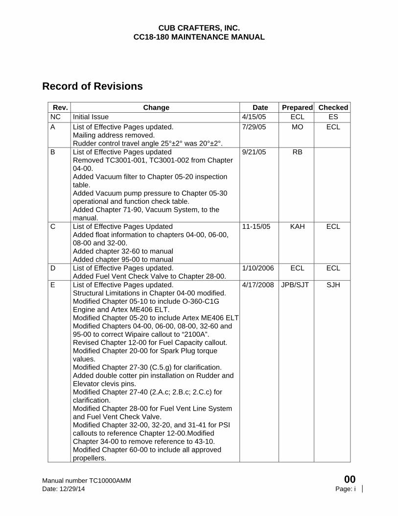
Record of Revisions
Rev. Change Date Prepared CheckedNC Initial Issue 4/15/05 ECL ES
A List of Effective Pages updated. Mailing address removed. Rudder control travel angle 25°±2° was 20°±2°.
7/29/05 MO ECL
B List of Effective Pages updated Removed TC3001-001, TC3001-002 from Chapter 04-00. Added Vacuum filter to Chapter 05-20 inspection table. Added Vacuum pump pressure to Chapter 05-30 operational and function check table. Added Chapter 71-90, Vacuum System, to the manual.
9/21/05 RB
C List of Effective Pages Updated Added float information to chapters 04-00, 06-00, 08-00 and 32-00. Added chapter 32-60 to manual Added chapter 95-00 to manual
11-15/05 KAH ECL
D List of Effective Pages updated. Added Fuel Vent Check Valve to Chapter 28-00.
1/10/2006 ECL ECL
E List of Effective Pages updated. Structural Limitations in Chapter 04-00 modified. Modified Chapter 05-10 to include O-360-C1G Engine and Artex ME406 ELT. Modified Chapter 05-20 to include Artex ME406 ELTModified Chapters 04-00, 06-00, 08-00, 32-60 and 95-00 to correct Wipaire callout to “2100A”. Revised Chapter 12-00 for Fuel Capacity callout. Modified Chapter 20-00 for Spark Plug torque values. Modified Chapter 27-30 (C.5.g) for clarification. Added double cotter pin installation on Rudder and Elevator clevis pins. Modified Chapter 27-40 (2.A.c; 2.B.c; 2.C.c) for clarification. Modified Chapter 28-00 for Fuel Vent Line System and Fuel Vent Check Valve. Modified Chapter 32-00, 32-20, and 31-41 for PSI callouts to reference Chapter 12-00.Modified Chapter 34-00 to remove reference to 43-10. Modified Chapter 60-00 to include all approved propellers.
4/17/2008 JPB/SJT SJH
CUB CRAFTERS, INC. CC18-180 MAINTENANCE MANUAL
00 Manual number TC10000AMM Page: ii Date: 12/29/14
Rev. Change Date Prepared CheckedModified Chapter 71-00 to include O-360-C1G Lycoming engine option. Modified Chapter 71-10 to remove C4P reference. Added Appendix A for Conversions.
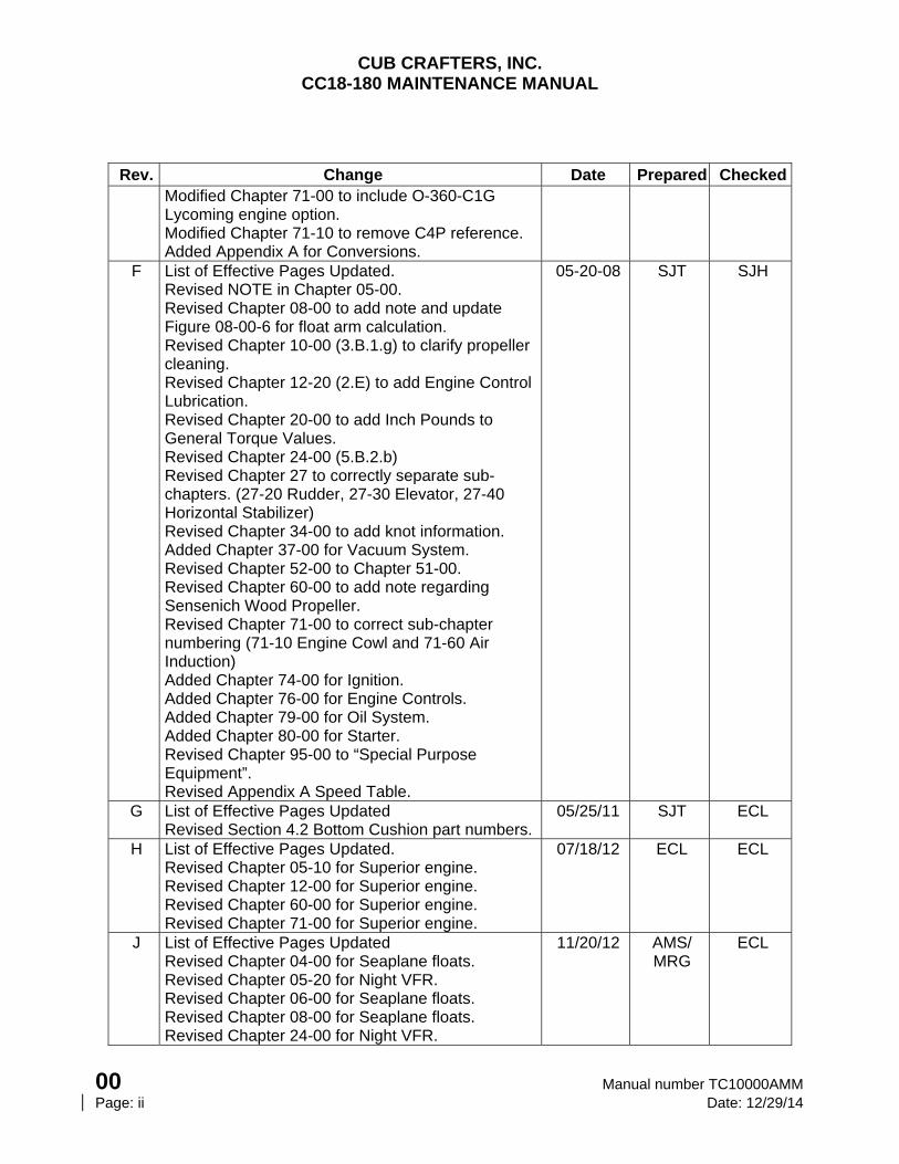
F List of Effective Pages Updated. Revised NOTE in Chapter 05-00. Revised Chapter 08-00 to add note and update Figure 08-00-6 for float arm calculation. Revised Chapter 10-00 (3.B.1.g) to clarify propeller cleaning. Revised Chapter 12-20 (2.E) to add Engine Control Lubrication. Revised Chapter 20-00 to add Inch Pounds to General Torque Values. Revised Chapter 24-00 (5.B.2.b) Revised Chapter 27 to correctly separate sub-chapters. (27-20 Rudder, 27-30 Elevator, 27-40 Horizontal Stabilizer) Revised Chapter 34-00 to add knot information. Added Chapter 37-00 for Vacuum System. Revised Chapter 52-00 to Chapter 51-00. Revised Chapter 60-00 to add note regarding Sensenich Wood Propeller. Revised Chapter 71-00 to correct sub-chapter numbering (71-10 Engine Cowl and 71-60 Air Induction) Added Chapter 74-00 for Ignition. Added Chapter 76-00 for Engine Controls. Added Chapter 79-00 for Oil System. Added Chapter 80-00 for Starter. Revised Chapter 95-00 to “Special Purpose Equipment”. Revised Appendix A Speed Table.
05-20-08 SJT SJH
G List of Effective Pages Updated Revised Section 4.2 Bottom Cushion part numbers.
05/25/11 SJT ECL
H List of Effective Pages Updated. Revised Chapter 05-10 for Superior engine. Revised Chapter 12-00 for Superior engine. Revised Chapter 60-00 for Superior engine. Revised Chapter 71-00 for Superior engine.
07/18/12 ECL ECL
J
List of Effective Pages Updated Revised Chapter 04-00 for Seaplane floats. Revised Chapter 05-20 for Night VFR. Revised Chapter 06-00 for Seaplane floats. Revised Chapter 08-00 for Seaplane floats. Revised Chapter 24-00 for Night VFR.
11/20/12
AMS/ MRG
ECL
CUB CRAFTERS, INC. CC18-180 MAINTENANCE MANUAL
Manual number TC10000AMM 00 Date: 12/29/14 Page: iii
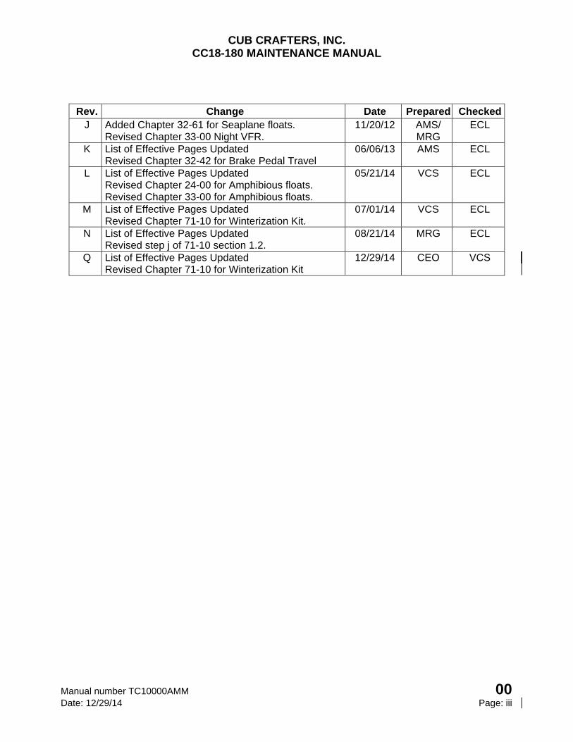
Rev. Change Date Prepared CheckedJ Added Chapter 32-61 for Seaplane floats.
Revised Chapter 33-00 Night VFR. 11/20/12 AMS/
MRG ECL
K List of Effective Pages Updated Revised Chapter 32-42 for Brake Pedal Travel
06/06/13 AMS ECL
L List of Effective Pages Updated Revised Chapter 24-00 for Amphibious floats. Revised Chapter 33-00 for Amphibious floats.
05/21/14 VCS ECL
M List of Effective Pages Updated Revised Chapter 71-10 for Winterization Kit.
07/01/14 VCS ECL
N List of Effective Pages Updated Revised step j of 71-10 section 1.2.
08/21/14 MRG ECL
Q List of Effective Pages Updated Revised Chapter 71-10 for Winterization Kit
12/29/14 CEO VCS
CUB CRAFTERS, INC. CC18-180 MAINTENANCE MANUAL
00 Manual number TC10000AMM Page: iv Date: 12/29/14
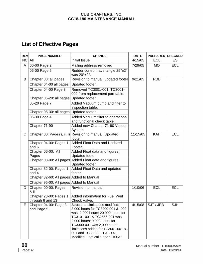
List of Effective Pages
REV PAGE NUMBER CHANGE DATE PREPARED CHECKED
NC All Initial Issue 4/15/05 ECL ES
A 00-00 Page 2 Mailing address removed 7/29/05 MO ECL
06-00 Page 5 Rudder control travel angle 25°±2° was 20°±2°.
B Chapter 00: all pages Revision to manual, updated footer 9/21/05 RBB
Chapter 04-00 all pages Updated footer.
Chapter 04-00 Page 3 Removed TC3001-001, TC3001-002 from replacement part table.
Chapter 05-20: all pages Updated footer.
05-20 Page 7 Added Vacuum pump and filter to inspection table.
Chapter 05-30: all pages Updated footer.
05-30 Page 4 Added Vacuum filter to operational and functional check table.
Chapter 71-90 Added new Chapter 71-90 Vacuum System
C Chapter 00: Pages i, ii, iii Revision to manual, Updated footer
11/15/05 KAH ECL
Chapter 04-00: Pages 1 and 6
Added Float Data and Updated Footer.
Chapter 06-00: All Pages
Added Float data and figures, Updated footer
Chapter 08-00: All pages Added Float data and figures, Updated footer
Chapter 32-00: Pages 1 and 4
Added Float Data and updated footer
Chapter 32-60: All pages Added to Manual
Chapter 95-00: All pages Added to Manual
D Chapter 00-00: Pages I & ii
Revision to manual 1/10/06 ECL ECL
Chapter 28-00: Pages 1 through 6 and 13
Added information for Fuel Vent Check Valve.
E Chapter 04-00: Page 3 and Page 5
Structural Limitations modified: 3,000 hours for TC3200-001 & -002 was 2,000 hours; 20,000 hours for TC3101-001 & TC2566-001 was 2,000 hours; 9,000 hours for TC3300-001 was 2,000 hours; limitations added for TC3001-001 & -001 and TC3002-001 & -002. Modified Float callout to “2100A”
4/15/08 SJT / JPB SJH
CUB CRAFTERS, INC. CC18-180 MAINTENANCE MANUAL
Manual number TC10000AMM 00 Date: 12/29/14 Page: v
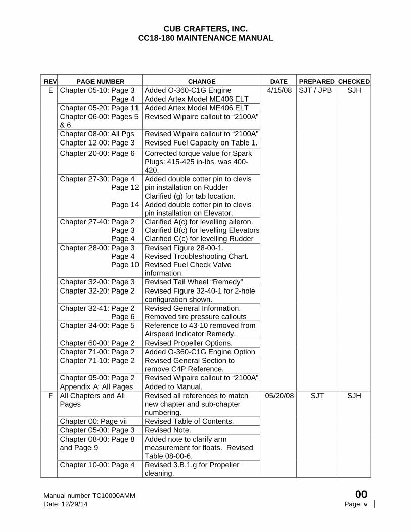
REV PAGE NUMBER CHANGE DATE PREPARED CHECKED
E Chapter 05-10: Page 3 Page 4
Added O-360-C1G Engine Added Artex Model ME406 ELT
4/15/08 SJT / JPB SJH
Chapter 05-20: Page 11 Added Artex Model ME406 ELT Chapter 06-00: Pages 5 & 6
Revised Wipaire callout to “2100A”
Chapter 08-00: All Pgs Revised Wipaire callout to “2100A”Chapter 12-00: Page 3 Revised Fuel Capacity on Table 1.
Chapter 20-00: Page 6 Corrected torque value for Spark Plugs: 415-425 in-lbs. was 400-420.
Chapter 27-30: Page 4 Page 12 Page 14
Added double cotter pin to clevis pin installation on Rudder Clarified (g) for tab location. Added double cotter pin to clevis pin installation on Elevator.
Chapter 27-40: Page 2 Page 3 Page 4
Clarified A(c) for levelling aileron. Clarified B(c) for levelling ElevatorsClarified C(c) for levelling Rudder
Chapter 28-00: Page 3 Page 4 Page 10
Revised Figure 28-00-1. Revised Troubleshooting Chart. Revised Fuel Check Valve information.
Chapter 32-00: Page 3 Revised Tail Wheel “Remedy” Chapter 32-20: Page 2 Revised Figure 32-40-1 for 2-hole
configuration shown. Chapter 32-41: Page 2 Page 6
Revised General Information. Removed tire pressure callouts
Chapter 34-00: Page 5 Reference to 43-10 removed from Airspeed Indicator Remedy.
Chapter 60-00: Page 2 Revised Propeller Options. Chapter 71-00: Page 2 Added O-360-C1G Engine Option Chapter 71-10: Page 2 Revised General Section to
remove C4P Reference. Chapter 95-00: Page 2 Revised Wipaire callout to “2100A”Appendix A: All Pages Added to Manual.
F All Chapters and All Pages
Revised all references to match new chapter and sub-chapter numbering.
05/20/08
SJT SJH
Chapter 00: Page vii Revised Table of Contents. Chapter 05-00: Page 3 Revised Note. Chapter 08-00: Page 8 and Page 9
Added note to clarify arm measurement for floats. Revised Table 08-00-6.
Chapter 10-00: Page 4 Revised 3.B.1.g for Propeller cleaning.
CUB CRAFTERS, INC. CC18-180 MAINTENANCE MANUAL
00 Manual number TC10000AMM Page: vi Date: 12/29/14
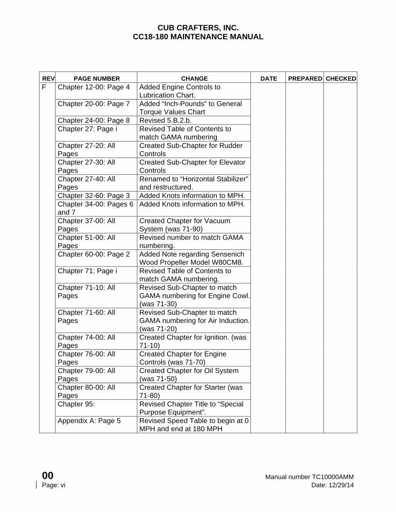
REV PAGE NUMBER CHANGE DATE PREPARED CHECKED
F Chapter 12-00: Page 4 Added Engine Controls to Lubrication Chart.
Chapter 20-00: Page 7 Added “Inch-Pounds” to General Torque Values Chart
Chapter 24-00: Page 8 Revised 5.B.2.b. Chapter 27: Page i Revised Table of Contents to
match GAMA numbering
Chapter 27-20: All Pages
Created Sub-Chapter for Rudder Controls
Chapter 27-30: All Pages
Created Sub-Chapter for Elevator Controls
Chapter 27-40: All Pages
Renamed to “Horizontal Stabilizer” and restructured.
Chapter 32-60: Page 3 Added Knots information to MPH. Chapter 34-00: Pages 6
and 7 Added Knots information to MPH.
Chapter 37-00: All Pages
Created Chapter for Vacuum System (was 71-90)
Chapter 51-00: All Pages
Revised number to match GAMA numbering.
Chapter 60-00: Page 2 Added Note regarding Sensenich Wood Propeller Model W80CM8.
Chapter 71: Page i Revised Table of Contents to match GAMA numbering.
Chapter 71-10: All Pages
Revised Sub-Chapter to match GAMA numbering for Engine Cowl. (was 71-30)
Chapter 71-60: All Pages
Revised Sub-Chapter to match GAMA numbering for Air Induction. (was 71-20)
Chapter 74-00: All Pages
Created Chapter for Ignition. (was 71-10)
Chapter 76-00: All Pages
Created Chapter for Engine Controls (was 71-70)
Chapter 79-00: All Pages
Created Chapter for Oil System (was 71-50)
Chapter 80-00: All Pages
Created Chapter for Starter (was 71-80)
Chapter 95: Revised Chapter Title to “Special Purpose Equipment”.
Appendix A: Page 5 Revised Speed Table to begin at 0 MPH and end at 180 MPH
CUB CRAFTERS, INC. CC18-180 MAINTENANCE MANUAL
Manual number TC10000AMM 00 Date: 12/29/14 Page: vii
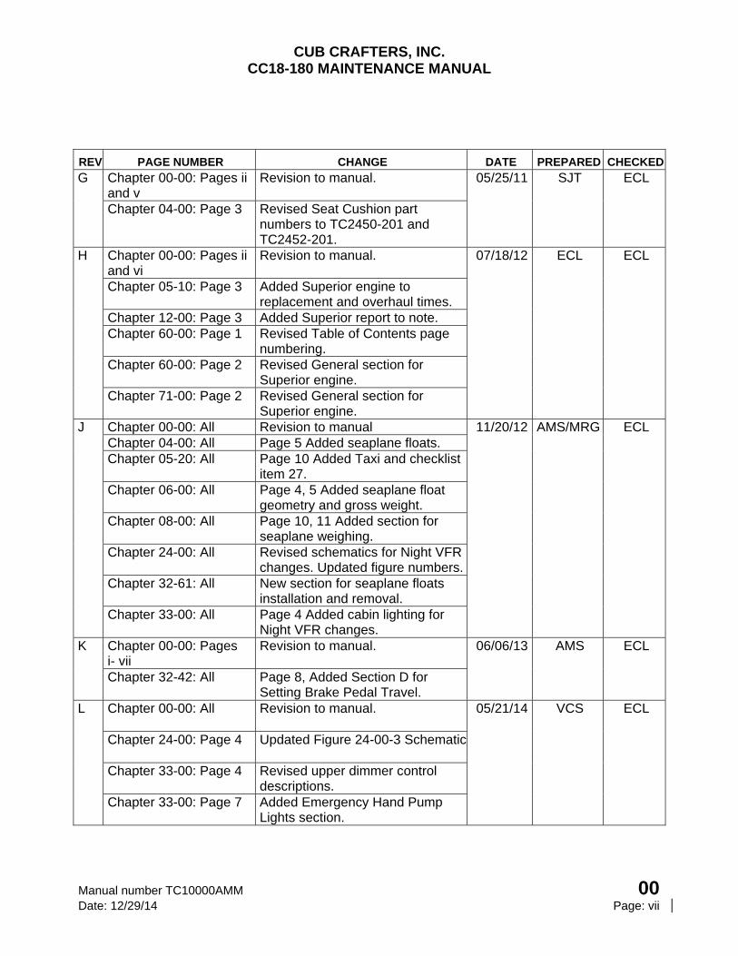
REV PAGE NUMBER CHANGE DATE PREPARED CHECKED
G Chapter 00-00: Pages ii and v
Revision to manual. 05/25/11 SJT ECL
Chapter 04-00: Page 3 Revised Seat Cushion part numbers to TC2450-201 and TC2452-201.
H Chapter 00-00: Pages ii and vi
Revision to manual. 07/18/12 ECL ECL
Chapter 05-10: Page 3 Added Superior engine to replacement and overhaul times.
Chapter 12-00: Page 3 Added Superior report to note. Chapter 60-00: Page 1 Revised Table of Contents page
numbering.
Chapter 60-00: Page 2 Revised General section for Superior engine.
Chapter 71-00: Page 2 Revised General section for Superior engine.
J Chapter 00-00: All Revision to manual 11/20/12 AMS/MRG ECL Chapter 04-00: All Page 5 Added seaplane floats. Chapter 05-20: All Page 10 Added Taxi and checklist
item 27. Chapter 06-00: All Page 4, 5 Added seaplane float
geometry and gross weight. Chapter 08-00: All Page 10, 11 Added section for
seaplane weighing. Chapter 24-00: All Revised schematics for Night VFR
changes. Updated figure numbers.Chapter 32-61: All New section for seaplane floats
installation and removal. Chapter 33-00: All Page 4 Added cabin lighting for
Night VFR changes. K Chapter 00-00: Pages
i- vii Revision to manual. 06/06/13 AMS ECL
Chapter 32-42: All Page 8, Added Section D for Setting Brake Pedal Travel.
L Chapter 00-00: All Revision to manual. 05/21/14 VCS ECL
Chapter 24-00: Page 4 Updated Figure 24-00-3 Schematic
Chapter 33-00: Page 4 Revised upper dimmer control descriptions.
Chapter 33-00: Page 7 Added Emergency Hand Pump Lights section.
CUB CRAFTERS, INC. CC18-180 MAINTENANCE MANUAL
00 Manual number TC10000AMM Page: viii Date: 12/29/14
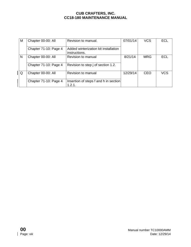
M Chapter 00-00: All Revision to manual. 07/01/14 VCS ECL
Chapter 71-10: Page 4 Added winterization kit installation instructions.
N Chapter 00-00: All Revision to manual 8/21/14 MRG ECL
Chapter 71-10: Page 4 Revision to step j of section 1.2.
Q Chapter 00-00: All Revision to manual 12/29/14 CEO VCS
Chapter 71-10: Page 4 Insertion of steps f and h in section 1.2.1.
CUB CRAFTERS, INC. CC18-180 MAINTENANCE MANUAL
Manual number TC10000AMM 00 Date: 12/29/14 Page: ix
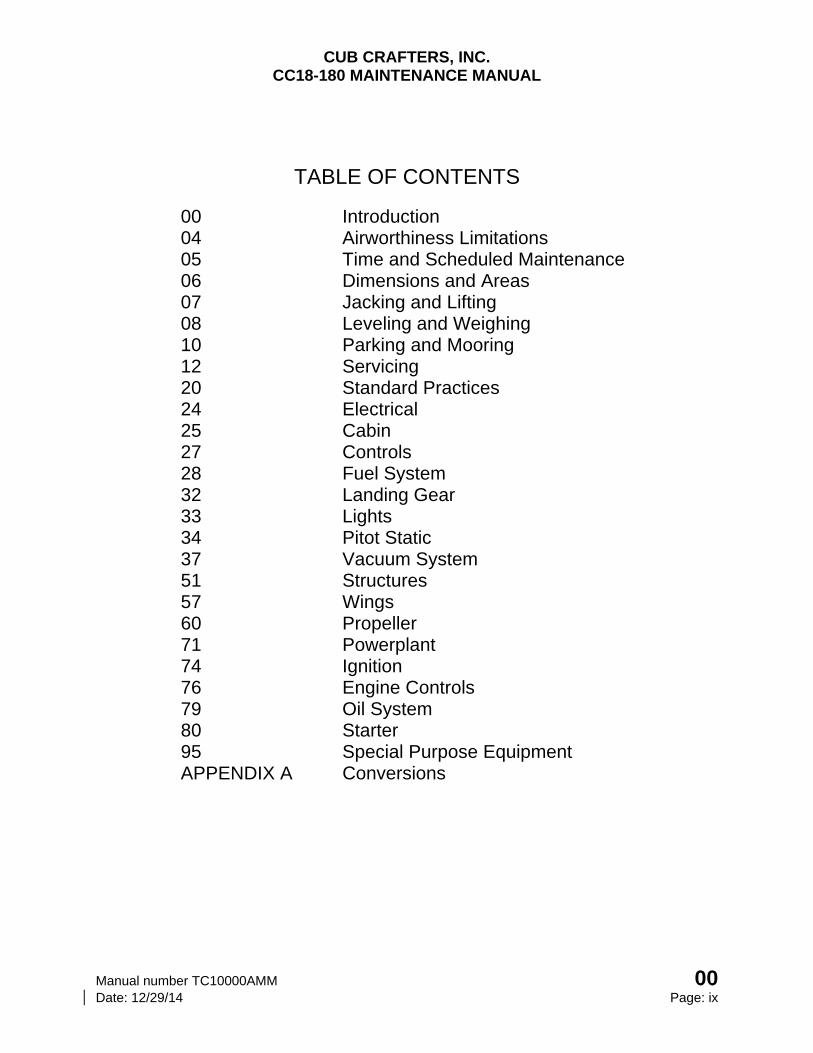
TABLE OF CONTENTS
00 Introduction 04 Airworthiness Limitations 05 Time and Scheduled Maintenance 06 Dimensions and Areas 07 Jacking and Lifting 08 Leveling and Weighing 10 Parking and Mooring 12 Servicing 20 Standard Practices 24 Electrical 25 Cabin 27 Controls 28 Fuel System 32 Landing Gear 33 Lights 34 Pitot Static 37 Vacuum System 51 Structures 57 Wings 60 Propeller 71 Powerplant 74 Ignition 76 Engine Controls 79 Oil System 80 Starter 95 Special Purpose Equipment APPENDIX A Conversions

CUB CRAFTERS, INC. CC18-180 MAINTENANCE MANUAL
Manual number TC10000AMM 00-00 Date: 12/29/14 Page: 1
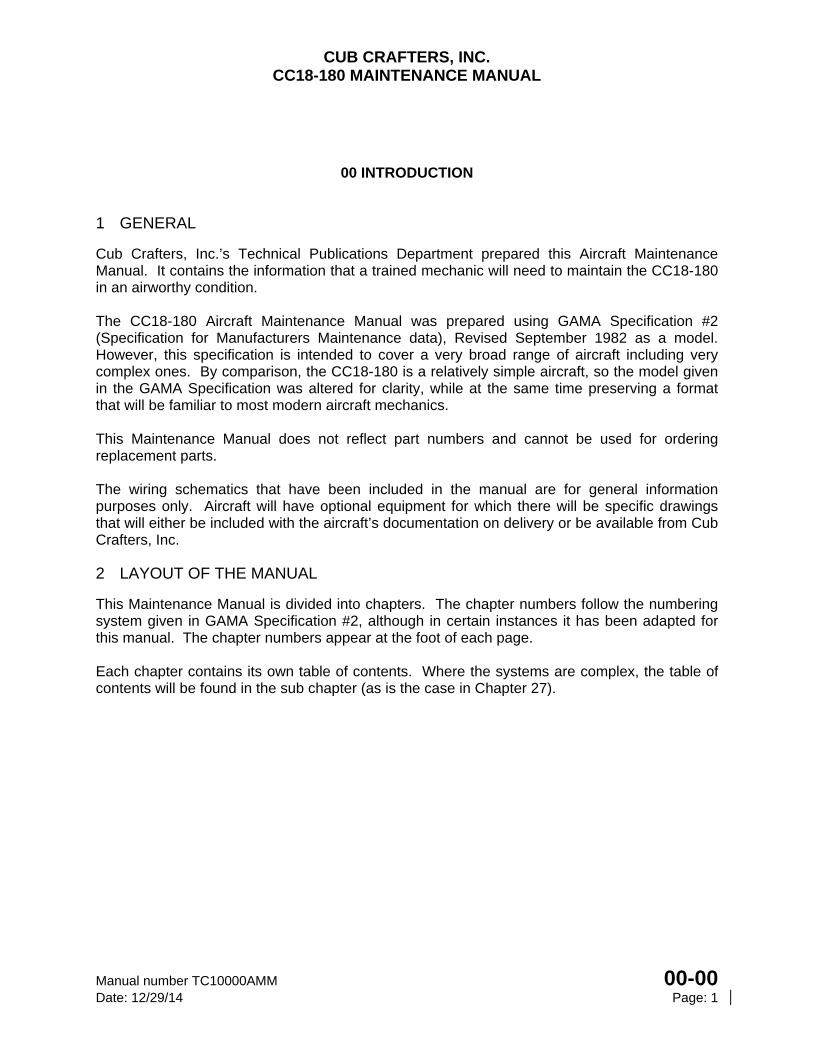
00 INTRODUCTION
1 GENERAL
Cub Crafters, Inc.’s Technical Publications Department prepared this Aircraft Maintenance Manual. It contains the information that a trained mechanic will need to maintain the CC18-180 in an airworthy condition. The CC18-180 Aircraft Maintenance Manual was prepared using GAMA Specification #2 (Specification for Manufacturers Maintenance data), Revised September 1982 as a model. However, this specification is intended to cover a very broad range of aircraft including very complex ones. By comparison, the CC18-180 is a relatively simple aircraft, so the model given in the GAMA Specification was altered for clarity, while at the same time preserving a format that will be familiar to most modern aircraft mechanics. This Maintenance Manual does not reflect part numbers and cannot be used for ordering replacement parts. The wiring schematics that have been included in the manual are for general information purposes only. Aircraft will have optional equipment for which there will be specific drawings that will either be included with the aircraft’s documentation on delivery or be available from Cub Crafters, Inc.
2 LAYOUT OF THE MANUAL
This Maintenance Manual is divided into chapters. The chapter numbers follow the numbering system given in GAMA Specification #2, although in certain instances it has been adapted for this manual. The chapter numbers appear at the foot of each page. Each chapter contains its own table of contents. Where the systems are complex, the table of contents will be found in the sub chapter (as is the case in Chapter 27).
CUB CRAFTERS, INC. CC18-180 MAINTENANCE MANUAL
00-00 Manual number TC10000AMM Page: 2 Date: 12/29/14
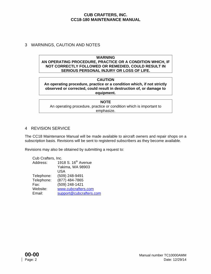
3 WARNINGS, CAUTION AND NOTES
WARNING
AN OPERATING PROCEDURE, PRACTICE OR A CONDITION WHICH, IF NOT CORRECTLY FOLLOWED OR REMEDIED, COULD RESULT IN
SERIOUS PERSONAL INJURY OR LOSS OF LIFE.
CAUTION An operating procedure, practice or a condition which, if not strictly observed or corrected, could result in destruction of, or damage to
equipment.
NOTE An operating procedure, practice or condition which is important to
emphasize.
4 REVISION SERVICE
The CC18 Maintenance Manual will be made available to aircraft owners and repair shops on a subscription basis. Revisions will be sent to registered subscribers as they become available. Revisions may also be obtained by submitting a request to:
Cub Crafters, Inc. Address: 1918 S. 16th Avenue Yakima, WA 98903 USA Telephone: (509) 248-9491 Telephone: (877) 484-7865 Fax: (509) 248-1421 Website: www.cubcrafters.com Email: [email protected]

CHAPTER
04-00
AIRWORTHINESS LIMITATIONS

CUB CRAFTERS, INC. CC18-180 MAINTENANCE MANUAL
Manual number TC10000AMM 04-00 Date: 11/20/12 Page 1
04-00 AIRWORTHINESS LIMITATIONS TABLE OF CONTENTS
1 GENERAL .............................................................................................................................. 2 2 DESCRIPTION ...................................................................................................................... 3
2.1 MAINTENANCE LIMITATIONS ...................................................................................... 3 2.2 REPLACEMENT INTERVALS ........................................................................................ 3 2.3 STRUCTURAL LIMIATATIONS ..................................................................................... 4 2.4 VORTEX GENERATORS ............................................................................................... 6 2.5 WIPAIRE 2100A AMPHIBIOUS and 2100S SEAPLANE FLOATS ................................ 6
CUB CRAFTERS, INC. CC18-180 MAINTENANCE MANUAL
04-00 Manual number TC10000AMM Page: 2 Date: 11/20/12
1 GENERAL
The FAA has approved the Airworthiness Limitations Section of this manual; it specifies inspection and maintenance required by paragraphs 43.16 and 91.403 of the Federal Aviation Regulations, unless an alternative program has been FAA approved. This chapter outlines replacement intervals, maintenance requirements and means of monitoring aircraft components, systems, and structures determined to be life limited.
CUB CRAFTERS, INC. CC18-180 MAINTENANCE MANUAL
Manual number TC10000AMM 04-00 Date: 11/20/12 Page 3
2 DESCRIPTION
The following airworthiness limitations and requirements are separated into five groups as described below.
Maintenance Limitations - Checks of components and systems that are required to be performed during scheduled maintenance.
Replacement Limitations - List of time limits at which Cub Crafters considers that specific components must be replaced.
Structural Limitations - Are related to fatigue life limitations as required by Federal Aviation Regulations for certification.
Vortex Generators - This limitation is related to the number of vortex generators that may be missing from an aircraft.
WIPAIRE 2100A Amphibious and 2100S Seaplane Floats – Restriction on propeller used in this configuration.
2.1 MAINTENANCE LIMITATIONS
The scheduled maintenance requirements are found in Chapter 5-20 (Scheduled Maintenance Checks).
2.2 REPLACEMENT INTERVALS Chapter 5-10 (Time Limits and Maintenance Checks - Overhaul and Replacement Schedule) lists replacement intervals that Cub Crafters considers essential for the safe continued airworthiness of the aircraft.
CUB CRAFTERS, INC. CC18-180 MAINTENANCE MANUAL
04-00 Manual number TC10000AMM Page 4 Date: 11/20/12
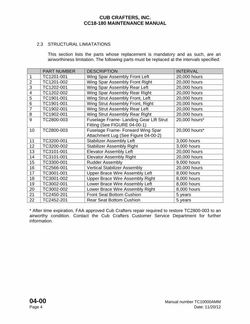
2.3 STRUCTURAL LIMIATATIONS
This section lists the parts whose replacement is mandatory and as such, are an airworthiness limitation. The following parts must be replaced at the intervals specified:
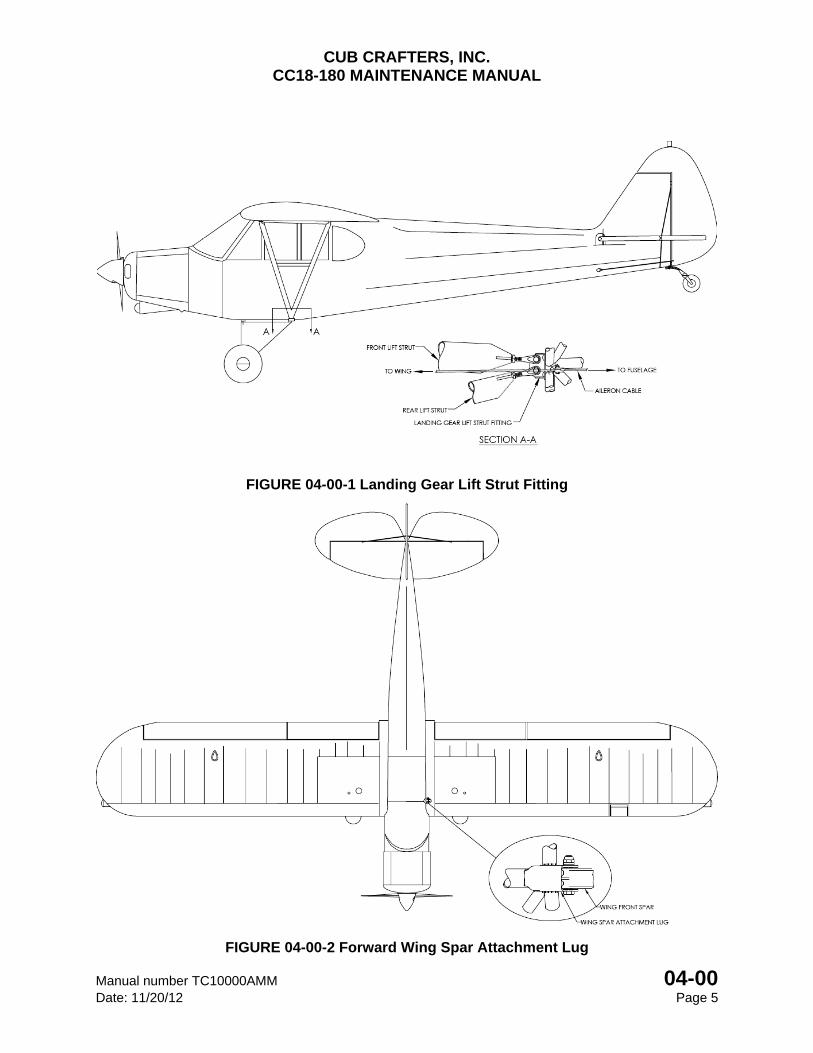
PART NUMBER DESCRIPTION INTERVAL 1 TC1201-001 Wing Spar Assembly Front Left 20,000 hours 2 TC1201-002 Wing Spar Assembly Front Right 20,000 hours 3 TC1202-001 Wing Spar Assembly Rear Left 20,000 hours 4 TC1202-002 Wing Spar Assembly Rear Right 20,000 hours 5 TC1901-001 Wing Strut Assembly Front, Left 20,000 hours 6 TC1901-001 Wing Strut Assembly Front, Right 20,000 hours 7 TC1902-001 Wing Strut Assembly Rear Left 20,000 hours 8 TC1902-001 Wing Strut Assembly Rear Right 20,000 hours 9 TC2800-003 Fuselage Frame- Landing Gear Lift Strut
Fitting (See FIGURE 04-00-1) 20,000 hours*
10 TC2800-003 Fuselage Frame- Forward Wing Spar Attachment Lug (See Figure 04-00-2)
20,000 hours*
11 TC3200-001 Stabilizer Assembly Left 3,000 hours 12 TC3200-002 Stabilizer Assembly Right 3,000 hours 13 TC3101-001 Elevator Assembly Left 20,000 hours 14 TC3101-001 Elevator Assembly Right 20,000 hours 15 TC3300-001 Rudder Assembly 9,000 hours 16 TC2566-001 Vertical Stabilizer Assembly 20,000 hours 17 TC3001-001 Upper Brace Wire Assembly Left 8,000 hours 18 TC3001-002 Upper Brace Wire Assembly Right 8,000 hours 19 TC3002-001 Lower Brace Wire Assembly Left 8,000 hours 20 TC3002-002 Lower Brace Wire Assembly Right 8,000 hours 21 TC2450-201 Front Seat Bottom Cushion 5 years 22 TC2452-201 Rear Seat Bottom Cushion 5 years * After time expiration, FAA approved Cub Crafters repair required to restore TC2800-003 to an airworthy condition. Contact the Cub Crafters Customer Service Department for further information.
CUB CRAFTERS, INC. CC18-180 MAINTENANCE MANUAL
Manual number TC10000AMM 04-00 Date: 11/20/12 Page 5
FIGURE 04-00-1 Landing Gear Lift Strut Fitting
FIGURE 04-00-2 Forward Wing Spar Attachment Lug
CUB CRAFTERS, INC. CC18-180 MAINTENANCE MANUAL
04-00 Manual number TC10000AMM Page 6 Date: 11/20/12
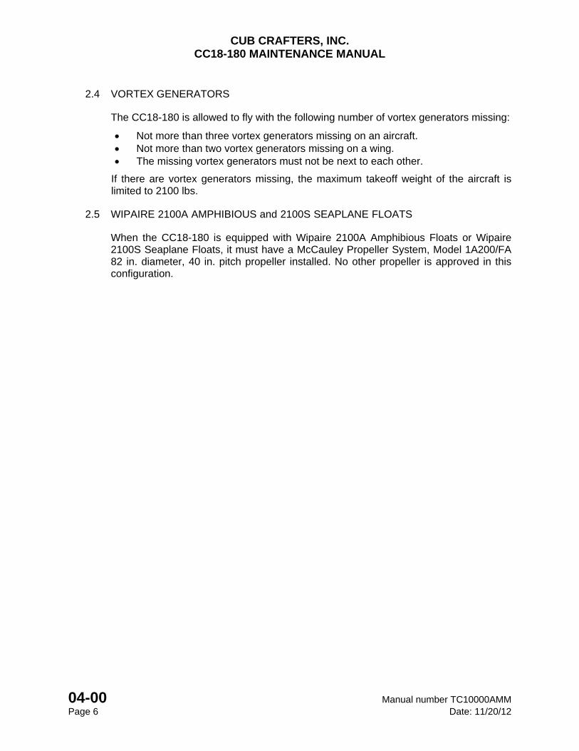
2.4 VORTEX GENERATORS
The CC18-180 is allowed to fly with the following number of vortex generators missing:
Not more than three vortex generators missing on an aircraft. Not more than two vortex generators missing on a wing. The missing vortex generators must not be next to each other.
If there are vortex generators missing, the maximum takeoff weight of the aircraft is limited to 2100 lbs.
2.5 WIPAIRE 2100A AMPHIBIOUS and 2100S SEAPLANE FLOATS
When the CC18-180 is equipped with Wipaire 2100A Amphibious Floats or Wipaire 2100S Seaplane Floats, it must have a McCauley Propeller System, Model 1A200/FA 82 in. diameter, 40 in. pitch propeller installed. No other propeller is approved in this configuration.
CHAPTER
05
TIME LIMITS AND SCHEDULED
MAINTENANCE

CUB CRAFTERS, INC. CC18-180 MAINTENANCE MANUAL
Manual number TC10000AMM 05 Date: 4/15/05 Page: i
05 TIME LIMITS AND SCHEDULED MAINTENANCE 05-00 .............................................................. TIME LIMITS AND SCHEDULED MAINTENANCE
05-10 ................................................................. OVERHAUL AND REPLACEMENT SCHEDULE
05-20 .............................................................................................. SCHEDULED MAINTENANCE
05-30 .............................................. OPERATIONAL AND FUNCTIONAL CHECK OF AIRCRAFT
CUB CRAFTERS, INC. CC18-180 MAINTENANCE MANUAL
05 Manual number TC10000AMM
Page: ii Date: 05/20/08
INTENTIONALLY LEFT BLANK
CUB CRAFTERS, INC. CC18-180 MAINTENANCE MANUAL
Manual number TC10000AMM 05-00 Date: 05/20/08 Page: 1
05-00 TIME LIMITS AND SCHEDULED MAINTENANCE
TABLE OF CONTENTS 1 GENERAL .............................................................................................................................. 2
2 ANNUAL INSPECTIONS ....................................................................................................... 2
3 100-HOUR INSPECTIONS .................................................................................................... 2
4 SPECIAL CONDITIONS - CAUTIONARY NOTICE ............................................................... 2
CUB CRAFTERS, INC. CC18-180 MAINTENANCE MANUAL
05-00 Manual number TC10000AMM Page: 2 Date: 05/20/08
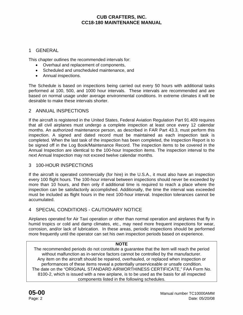
1 GENERAL
This chapter outlines the recommended intervals for: Overhaul and replacement of components, Scheduled and unscheduled maintenance, and Annual inspections.
The Schedule is based on inspections being carried out every 50 hours with additional tasks performed at 100, 500, and 1000 hour intervals. These intervals are recommended and are based on normal usage under average environmental conditions. In extreme climates it will be desirable to make these intervals shorter.
2 ANNUAL INSPECTIONS
If the aircraft is registered in the United States, Federal Aviation Regulation Part 91.409 requires that all civil airplanes must undergo a complete inspection at least once every 12 calendar months. An authorized maintenance person, as described in FAR Part 43.3, must perform this inspection. A signed and dated record must be maintained as each inspection task is completed. When the last task of the inspection has been completed, the Inspection Report is to be signed off in the Log Book/Maintenance Record. The inspection items to be covered in the Annual Inspection are identical to the 100-hour Inspection items. The inspection interval to the next Annual Inspection may not exceed twelve calendar months.
3 100-HOUR INSPECTIONS
If the aircraft is operated commercially (for hire) in the U.S.A., it must also have an inspection every 100 flight hours. The 100-hour interval between inspections should never be exceeded by more than 10 hours, and then only if additional time is required to reach a place where the inspection can be satisfactorily accomplished. Additionally, the time the interval was exceeded must be included as flight hours in the next 100-hour interval. Inspection tolerances cannot be accumulated.
4 SPECIAL CONDITIONS - CAUTIONARY NOTICE
Airplanes operated for Air Taxi operation or other than normal operation and airplanes that fly in humid tropics or cold and damp climates, etc., may need more frequent inspections for wear, corrosion, and/or lack of lubrication. In these areas, periodic inspections should be performed more frequently until the operator can set his own inspection periods based on experience.
NOTE The recommended periods do not constitute a guarantee that the item will reach the period
without malfunction as in-service factors cannot be controlled by the manufacturer. Any item on the aircraft should be repaired, overhauled, or replaced when inspection or
performances of these items reveal a potentially unserviceable or unsafe condition. The date on the “ORIGINAL STANDARD AIRWORTHINESS CERTIFICATE,” FAA Form No.
8100-2, which is issued with a new airplane, is to be used as the basis for all inspected components listed in the following schedules.
CUB CRAFTERS, INC. CC18-180 MAINTENANCE MANUAL
Manual number TC10000AMM 05-10 Date: 06/20/14 Page: 1
05-10 OVERHAUL AND REPLACEMENT SCHEDULE
TABLE OF CONTENTS
1 GENERAL ......................................................................................................................... 2
2 REPLACEMENT AND OVERHAUL TIMES ...................................................................... 3
CUB CRAFTERS, INC. CC18-180 MAINTENANCE MANUAL
05-10 Manual number TC10000AMM Page: 2 Date: 06/20/14
1 GENERAL
This section lists the components that Cub Crafters recommends be overhauled or replaced at specified intervals. Whenever this is carried out, ensure that the following information is properly recorded in the Airplane Maintenance Log:
Date of removal, installation, or overhaul of the component Time on the component since last overhaul (if appropriate) Aircraft’s flight hours
CUB CRAFTERS, INC. CC18-180 MAINTENANCE MANUAL
Manual number TC10000AMM 05-10 Date: 06/20/14 Page: 3
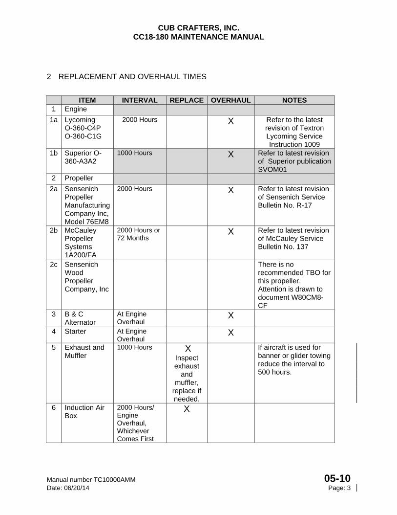
2 REPLACEMENT AND OVERHAUL TIMES
ITEM INTERVAL REPLACE OVERHAUL NOTES 1 Engine
1a Lycoming O-360-C4P O-360-C1G
2000 Hours
X Refer to the latest revision of Textron Lycoming Service Instruction 1009
1b Superior O-360-A3A2
1000 Hours X Refer to latest revision of Superior publication SVOM01
2 Propeller
2a Sensenich Propeller Manufacturing Company Inc, Model 76EM8
2000 Hours X Refer to latest revision of Sensenich Service Bulletin No. R-17
2b McCauley Propeller Systems 1A200/FA
2000 Hours or 72 Months
X Refer to latest revision of McCauley Service Bulletin No. 137
2c Sensenich Wood Propeller Company, Inc
There is no recommended TBO for this propeller. Attention is drawn to document W80CM8-CF
3 B & C Alternator
At Engine Overhaul
X
4 Starter At Engine Overhaul
X
5 Exhaust and Muffler
1000 Hours X Inspect exhaust
and muffler,
replace if needed.
If aircraft is used for banner or glider towing reduce the interval to 500 hours.
6 Induction Air Box
2000 Hours/ Engine Overhaul, Whichever Comes First
X
CUB CRAFTERS, INC. CC18-180 MAINTENANCE MANUAL
05-10 Manual number TC10000AMM Page: 4 Date: 06/20/14
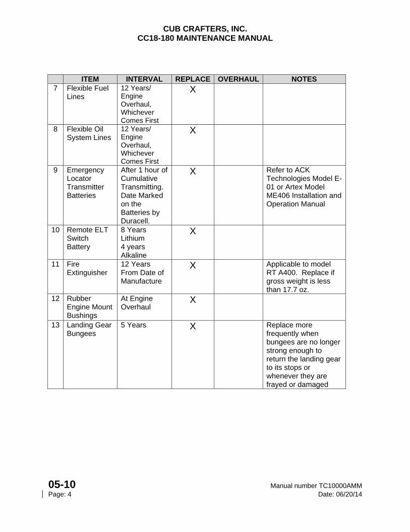
ITEM INTERVAL REPLACE OVERHAUL NOTES 7 Flexible Fuel
Lines 12 Years/ Engine Overhaul, Whichever Comes First
X
8 Flexible Oil System Lines
12 Years/ Engine Overhaul, Whichever Comes First
X
9 Emergency Locator Transmitter Batteries
After 1 hour of Cumulative Transmitting. Date Marked on the Batteries by Duracell.
X Refer to ACK Technologies Model E-01 or Artex Model ME406 Installation and Operation Manual
10 Remote ELT Switch Battery
8 Years Lithium 4 years Alkaline
X
11 Fire Extinguisher
12 Years From Date of Manufacture
X Applicable to model RT A400. Replace if gross weight is less than 17.7 oz.
12 Rubber Engine Mount Bushings
At Engine Overhaul
X
13 Landing Gear Bungees
5 Years X Replace more frequently when bungees are no longer strong enough to return the landing gear to its stops or whenever they are frayed or damaged
CUB CRAFTERS, INC. CC18-180 MAINTENANCE MANUAL
Manual number TC10000AMM 05-20 Date: 11/20/12 Page: 1
05-20 SCHEDULED MAINTENANCE
TABLE OF CONTENTS
1 GENERAL ............................................................................................................................. 2
2 INSPECTION GROUPS AND CRITERIA ............................................................................. 2
2.1 Visual Inspection ........................................................................................................... 2
2.2 Operational Inspection .................................................................................................. 3
2.3 Functional Inspection .................................................................................................... 3
3 INSPECTION FORMS .......................................................................................................... 4
CUB CRAFTERS, INC. CC18-180 MAINTENANCE MANUAL
05-20 Manual number TC10000AMM Page: 2 Date: 11/20/12
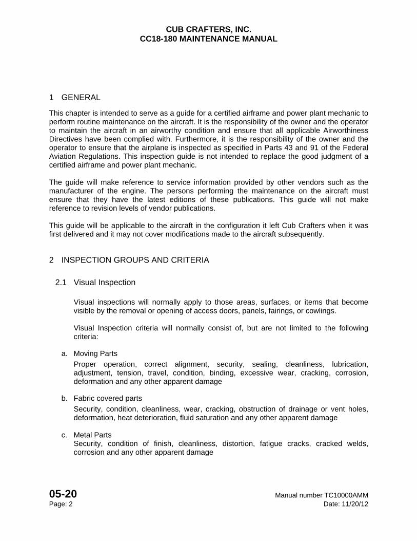
1 GENERAL
This chapter is intended to serve as a guide for a certified airframe and power plant mechanic to perform routine maintenance on the aircraft. It is the responsibility of the owner and the operator to maintain the aircraft in an airworthy condition and ensure that all applicable Airworthiness Directives have been complied with. Furthermore, it is the responsibility of the owner and the operator to ensure that the airplane is inspected as specified in Parts 43 and 91 of the Federal Aviation Regulations. This inspection guide is not intended to replace the good judgment of a certified airframe and power plant mechanic. The guide will make reference to service information provided by other vendors such as the manufacturer of the engine. The persons performing the maintenance on the aircraft must ensure that they have the latest editions of these publications. This guide will not make reference to revision levels of vendor publications. This guide will be applicable to the aircraft in the configuration it left Cub Crafters when it was first delivered and it may not cover modifications made to the aircraft subsequently.
2 INSPECTION GROUPS AND CRITERIA
2.1 Visual Inspection
Visual inspections will normally apply to those areas, surfaces, or items that become visible by the removal or opening of access doors, panels, fairings, or cowlings.
Visual Inspection criteria will normally consist of, but are not limited to the following criteria:
a. Moving Parts
Proper operation, correct alignment, security, sealing, cleanliness, lubrication, adjustment, tension, travel, condition, binding, excessive wear, cracking, corrosion, deformation and any other apparent damage
b. Fabric covered parts
Security, condition, cleanliness, wear, cracking, obstruction of drainage or vent holes, deformation, heat deterioration, fluid saturation and any other apparent damage
c. Metal Parts Security, condition of finish, cleanliness, distortion, fatigue cracks, cracked welds, corrosion and any other apparent damage
CUB CRAFTERS, INC. CC18-180 MAINTENANCE MANUAL
Manual number TC10000AMM 05-20 Date: 11/20/12 Page: 3
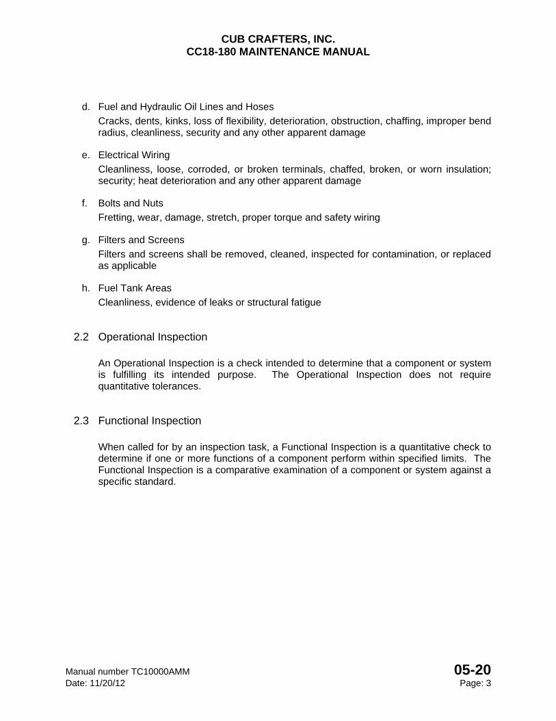
d. Fuel and Hydraulic Oil Lines and Hoses
Cracks, dents, kinks, loss of flexibility, deterioration, obstruction, chaffing, improper bend radius, cleanliness, security and any other apparent damage
e. Electrical Wiring
Cleanliness, loose, corroded, or broken terminals, chaffed, broken, or worn insulation; security; heat deterioration and any other apparent damage
f. Bolts and Nuts
Fretting, wear, damage, stretch, proper torque and safety wiring
g. Filters and Screens
Filters and screens shall be removed, cleaned, inspected for contamination, or replaced as applicable
h. Fuel Tank Areas
Cleanliness, evidence of leaks or structural fatigue
2.2 Operational Inspection
An Operational Inspection is a check intended to determine that a component or system is fulfilling its intended purpose. The Operational Inspection does not require quantitative tolerances.
2.3 Functional Inspection
When called for by an inspection task, a Functional Inspection is a quantitative check to determine if one or more functions of a component perform within specified limits. The Functional Inspection is a comparative examination of a component or system against a specific standard.
CUB CRAFTERS, INC. CC18-180 MAINTENANCE MANUAL
05-20 Manual number TC10000AMM Page: 4 Date: 11/20/12
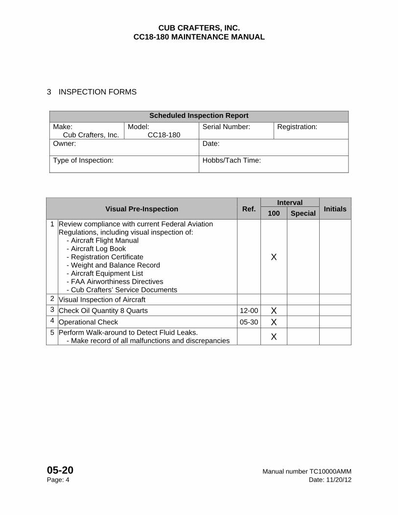
3 INSPECTION FORMS
Scheduled Inspection Report
Make: Cub Crafters, Inc.
Model: CC18-180
Serial Number: Registration:
Owner:
Date:
Type of Inspection:
Hobbs/Tach Time:
Visual Pre-Inspection Ref. Interval
Initials 100 Special
1 Review compliance with current Federal Aviation Regulations, including visual inspection of: - Aircraft Flight Manual - Aircraft Log Book - Registration Certificate - Weight and Balance Record - Aircraft Equipment List - FAA Airworthiness Directives - Cub Crafters’ Service Documents
X
2 Visual Inspection of Aircraft 3 Check Oil Quantity 8 Quarts 12-00 X 4 Operational Check 05-30 X
5 Perform Walk-around to Detect Fluid Leaks. - Make record of all malfunctions and discrepancies
X
CUB CRAFTERS, INC. CC18-180 MAINTENANCE MANUAL
Manual number TC10000AMM 05-20 Date: 11/20/12 Page: 5
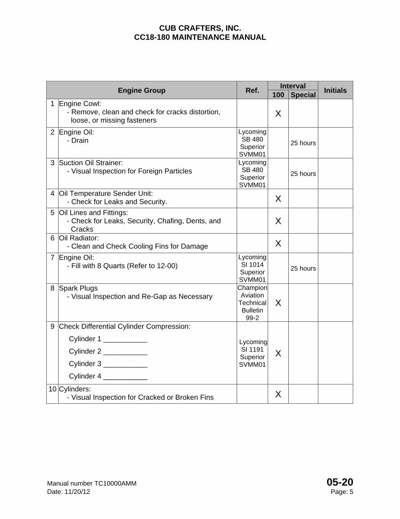
Engine Group Ref. Interval
Initials 100 Special
1 Engine Cowl: - Remove, clean and check for cracks distortion, loose, or missing fasteners
X
2 Engine Oil: - Drain
Lycoming SB 480 Superior SVMM01
25 hours
3 Suction Oil Strainer: - Visual Inspection for Foreign Particles
Lycoming SB 480 Superior SVMM01
25 hours
4 Oil Temperature Sender Unit: - Check for Leaks and Security. X
5 Oil Lines and Fittings: - Check for Leaks, Security, Chafing, Dents, and Cracks
X
6 Oil Radiator: - Clean and Check Cooling Fins for Damage X
7 Engine Oil: - Fill with 8 Quarts (Refer to 12-00)
Lycoming SI 1014 Superior SVMM01
25 hours
8 Spark Plugs - Visual Inspection and Re-Gap as Necessary
Champion Aviation
Technical Bulletin
99-2
X
9 Check Differential Cylinder Compression:
Cylinder 1 ___________
Cylinder 2 ___________
Cylinder 3 ___________
Cylinder 4 ___________
Lycoming SI 1191 Superior SVMM01
X
10 Cylinders: - Visual Inspection for Cracked or Broken Fins X
CUB CRAFTERS, INC. CC18-180 MAINTENANCE MANUAL
05-20 Manual number TC10000AMM Page: 6 Date: 11/20/12
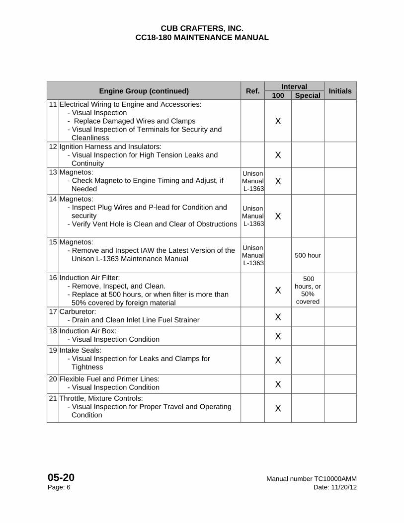
Engine Group (continued) Ref. Interval
Initials 100 Special
11 Electrical Wiring to Engine and Accessories: - Visual Inspection - Replace Damaged Wires and Clamps - Visual Inspection of Terminals for Security and Cleanliness
X
12 Ignition Harness and Insulators: - Visual Inspection for High Tension Leaks and Continuity
X
13 Magnetos: - Check Magneto to Engine Timing and Adjust, if Needed
Unison Manual L-1363
X
14 Magnetos: - Inspect Plug Wires and P-lead for Condition and security - Verify Vent Hole is Clean and Clear of Obstructions
Unison Manual L-1363
X
15 Magnetos: - Remove and Inspect IAW the Latest Version of the Unison L-1363 Maintenance Manual
Unison Manual L-1363
500 hour
16 Induction Air Filter: - Remove, Inspect, and Clean. - Replace at 500 hours, or when filter is more than 50% covered by foreign material
X 500
hours, or 50%
covered
17 Carburetor: - Drain and Clean Inlet Line Fuel Strainer X
18 Induction Air Box: - Visual Inspection Condition X
19 Intake Seals: - Visual Inspection for Leaks and Clamps for Tightness
X
20 Flexible Fuel and Primer Lines: - Visual Inspection Condition X
21 Throttle, Mixture Controls: - Visual Inspection for Proper Travel and Operating Condition
X
CUB CRAFTERS, INC. CC18-180 MAINTENANCE MANUAL
Manual number TC10000AMM 05-20 Date: 11/20/12 Page: 7
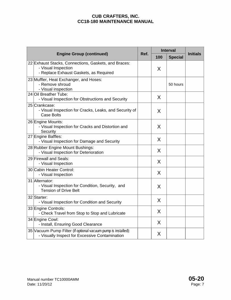
Engine Group (continued) Ref. Interval
Initials 100 Special
22 Exhaust Stacks, Connections, Gaskets, and Braces: - Visual Inspection - Replace Exhaust Gaskets, as Required
X
23 Muffler, Heat Exchanger, and Hoses: - Remove shroud - Visual inspection
50 hours
24 Oil Breather Tube: - Visual Inspection for Obstructions and Security X
25 Crankcase: - Visual Inspection for Cracks, Leaks, and Security of Case Bolts
X
26 Engine Mounts: - Visual Inspection for Cracks and Distortion and Security
X
27 Engine Baffles: - Visual Inspection for Damage and Security X
28 Rubber Engine Mount Bushings: - Visual Inspection for Deterioration X
29 Firewall and Seals: - Visual Inspection X
30 Cabin Heater Control: - Visual Inspection X
31 Alternator: - Visual Inspection for Condition, Security, and Tension of Drive Belt
X
32 Starter: - Visual Inspection for Condition and Security X
33 Engine Controls: - Check Travel from Stop to Stop and Lubricate X
34 Engine Cowl: - Install, Ensuring Good Clearance X
35 Vacuum Pump Filter (if optional vacuum pump is installed): - Visually Inspect for Excessive Contamination X

CUB CRAFTERS, INC. CC18-180 MAINTENANCE MANUAL
05-20 Manual number TC10000AMM Page: 8 Date: 11/20/12
Propeller Group – Metal Ref. Interval
Initials 100 Special
THIS INSPECTION SHEET IS APPLICABLE TO THE SENSENICH PROPELLER MANUFACTURING CO. MODEL 76EM8 PROPELLER AND MCCAULEY PROPELLER
SYSTEMS 1A200/FA82.1 Spinner and Bulkheads:
- Visual Inspection for Damage and Security X
2 Propeller Blades: - Visual Inspection for Nicks and Cracks
X
3 Spinner Mounting Brackets: - Visual Inspection for Damage and Security
X
4 Propeller Mounting Bolts: - Visual Inspection - Check Torque, If Safety Wire is Broken
X
Propeller Group - Wood Ref.
Interval Initials
100 Special
THIS INSPECTION SHEET IS APPLICABLE TO THE SENSENICH WOOD PROPELLER CO., W80CM8 PROPELLER.
1 Spinner and Back Plate: - Visual Inspection for Damage and Security 50 hours
2 Propeller Hub and Blades: - Visual Inspection for Nicks and Cracks
Sensenich Bulletin
Doc W80CM8-
CF
50 hours
3 Propeller Mounting Bolts: - Torque Verification after 1st Flight, 25 Hours, and Every 50 Hours thereafter or Should the Operating Environment Change
If below 200 in-lbs.: - Remove Propeller and Inspect Hub for Damage
Between 200-275 in-lbs.: - Adjust torque
Between 275-325 in-lbs. - No Further Action Required
Above 325 in-lbs.: - Loosen Bolts and Re-Torque
1st Flight,
25 hours,
50 hours,
Environ.
CUB CRAFTERS, INC. CC18-180 MAINTENANCE MANUAL
Manual number TC10000AMM 05-20 Date: 11/20/12 Page: 9
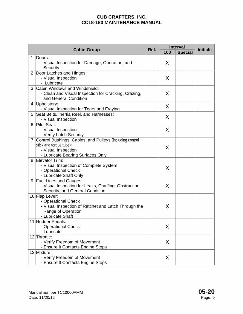
Cabin Group Ref. Interval
Initials 100 Special
1 Doors: - Visual Inspection for Damage, Operation, and Security
X
2 Door Latches and Hinges: - Visual Inspection - Lubricate
X
3 Cabin Windows and Windshield: - Clean and Visual Inspection for Cracking, Crazing, and General Condition
X
4 Upholstery: - Visual Inspection for Tears and Fraying
X
5 Seat Belts, Inertia Reel, and Harnesses: - Visual Inspection
X
6 Pilot Seat: - Visual Inspection - Verify Latch Security
X
7 Control Bushings, Cables, and Pulleys (including control stick and torque tube): - Visual Inspection - Lubricate Bearing Surfaces Only
X
8 Elevator Trim: - Visual Inspection of Complete System - Operational Check - Lubricate Shaft Only
X
9 Fuel Lines and Gauges: - Visual Inspection for Leaks, Chaffing, Obstruction, Security, and General Condition
X
10 Flap Lever: - Operational Check - Visual Inspection of Ratchet and Latch Through the Range of Operation - Lubricate Shaft
X
11 Rudder Pedals: - Operational Check - Lubricate
X
12 Throttle: - Verify Freedom of Movement - Ensure It Contacts Engine Stops
X
13 Mixture: - Verify Freedom of Movement - Ensure It Contacts Engine Stops
X
CUB CRAFTERS, INC. CC18-180 MAINTENANCE MANUAL
05-20 Manual number TC10000AMM Page: 10 Date: 11/20/12
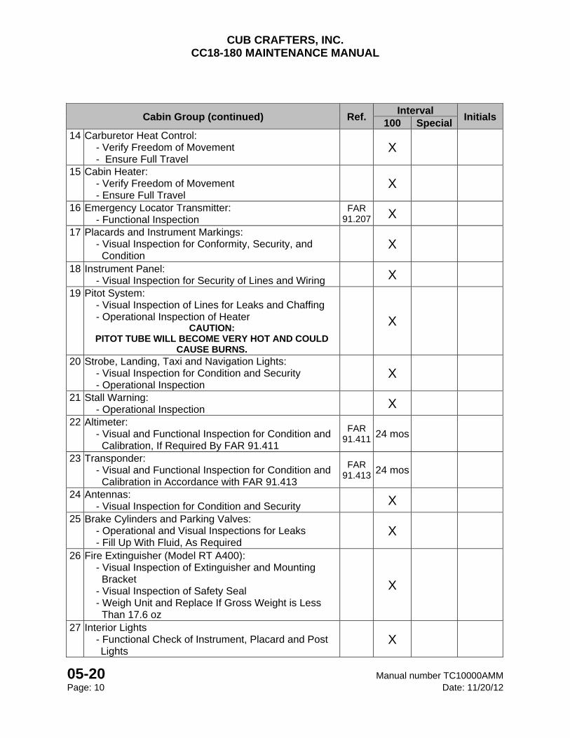
Cabin Group (continued) Ref. Interval
Initials 100 Special
14 Carburetor Heat Control: - Verify Freedom of Movement - Ensure Full Travel
X
15 Cabin Heater: - Verify Freedom of Movement - Ensure Full Travel
X
16 Emergency Locator Transmitter: - Functional Inspection
FAR 91.207 X
17 Placards and Instrument Markings: - Visual Inspection for Conformity, Security, and Condition
X
18 Instrument Panel: - Visual Inspection for Security of Lines and Wiring
X
19 Pitot System: - Visual Inspection of Lines for Leaks and Chaffing - Operational Inspection of Heater
CAUTION: PITOT TUBE WILL BECOME VERY HOT AND COULD
CAUSE BURNS.
X
20 Strobe, Landing, Taxi and Navigation Lights: - Visual Inspection for Condition and Security - Operational Inspection
X
21 Stall Warning: - Operational Inspection
X
22 Altimeter: - Visual and Functional Inspection for Condition and Calibration, If Required By FAR 91.411
FAR 91.411 24 mos
23 Transponder: - Visual and Functional Inspection for Condition and Calibration in Accordance with FAR 91.413
FAR 91.413 24 mos
24 Antennas: - Visual Inspection for Condition and Security
X
25 Brake Cylinders and Parking Valves: - Operational and Visual Inspections for Leaks - Fill Up With Fluid, As Required
X
26 Fire Extinguisher (Model RT A400): - Visual Inspection of Extinguisher and Mounting Bracket - Visual Inspection of Safety Seal - Weigh Unit and Replace If Gross Weight is Less Than 17.6 oz
X
27 Interior Lights - Functional Check of Instrument, Placard and Post
Lights X
CUB CRAFTERS, INC. CC18-180 MAINTENANCE MANUAL
Manual number TC10000AMM 05-20 Date: 11/20/12 Page: 11
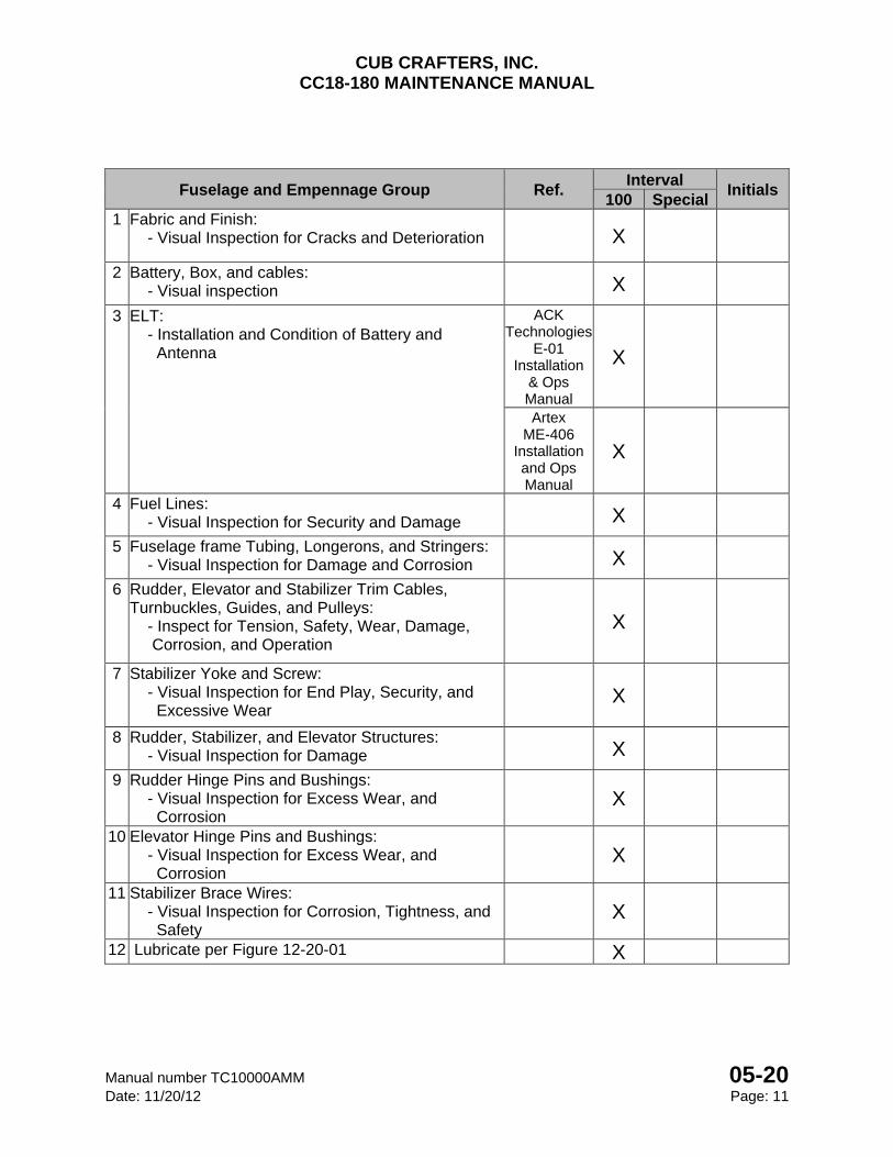
Fuselage and Empennage Group Ref. Interval
Initials 100 Special
1 Fabric and Finish: - Visual Inspection for Cracks and Deterioration X
2 Battery, Box, and cables: - Visual inspection X
3 ELT: - Installation and Condition of Battery and Antenna
ACK Technologies
E-01 Installation
& Ops Manual
X
Artex ME-406
Installation and Ops Manual
X
4 Fuel Lines: - Visual Inspection for Security and Damage X
5 Fuselage frame Tubing, Longerons, and Stringers: - Visual Inspection for Damage and Corrosion X
6 Rudder, Elevator and Stabilizer Trim Cables, Turnbuckles, Guides, and Pulleys: - Inspect for Tension, Safety, Wear, Damage, Corrosion, and Operation
X
7 Stabilizer Yoke and Screw: - Visual Inspection for End Play, Security, and Excessive Wear
X
8 Rudder, Stabilizer, and Elevator Structures: - Visual Inspection for Damage X
9 Rudder Hinge Pins and Bushings: - Visual Inspection for Excess Wear, and Corrosion
X
10 Elevator Hinge Pins and Bushings: - Visual Inspection for Excess Wear, and Corrosion
X
11 Stabilizer Brace Wires: - Visual Inspection for Corrosion, Tightness, and Safety
X
12 Lubricate per Figure 12-20-01 X
CUB CRAFTERS, INC. CC18-180 MAINTENANCE MANUAL
05-20 Manual number TC10000AMM Page: 12 Date: 11/20/12
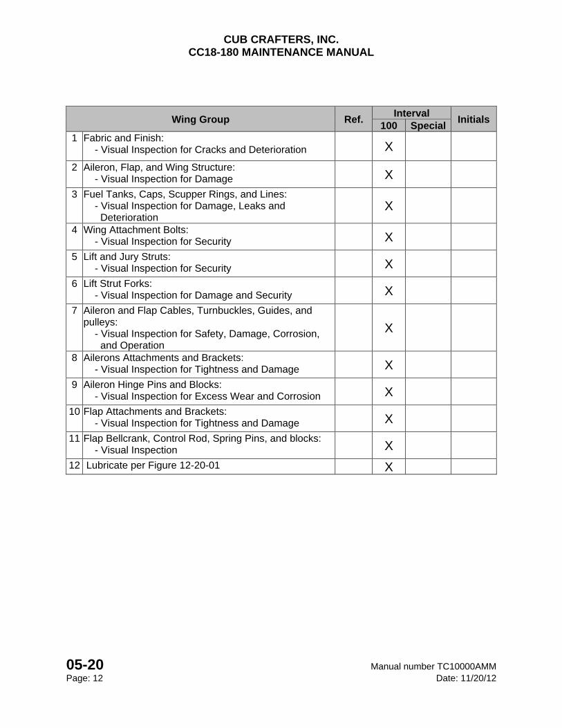
Wing Group Ref. Interval
Initials 100 Special
1 Fabric and Finish: - Visual Inspection for Cracks and Deterioration X
2 Aileron, Flap, and Wing Structure: - Visual Inspection for Damage X
3 Fuel Tanks, Caps, Scupper Rings, and Lines: - Visual Inspection for Damage, Leaks and Deterioration
X
4 Wing Attachment Bolts: - Visual Inspection for Security X
5 Lift and Jury Struts: - Visual Inspection for Security X
6 Lift Strut Forks: - Visual Inspection for Damage and Security X
7 Aileron and Flap Cables, Turnbuckles, Guides, and pulleys: - Visual Inspection for Safety, Damage, Corrosion, and Operation
X
8 Ailerons Attachments and Brackets: - Visual Inspection for Tightness and Damage X
9 Aileron Hinge Pins and Blocks: - Visual Inspection for Excess Wear and Corrosion X
10 Flap Attachments and Brackets: - Visual Inspection for Tightness and Damage X
11 Flap Bellcrank, Control Rod, Spring Pins, and blocks: - Visual Inspection X
12 Lubricate per Figure 12-20-01 X
CUB CRAFTERS, INC. CC18-180 MAINTENANCE MANUAL
Manual number TC10000AMM 05-20 Date: 11/20/12 Page: 13
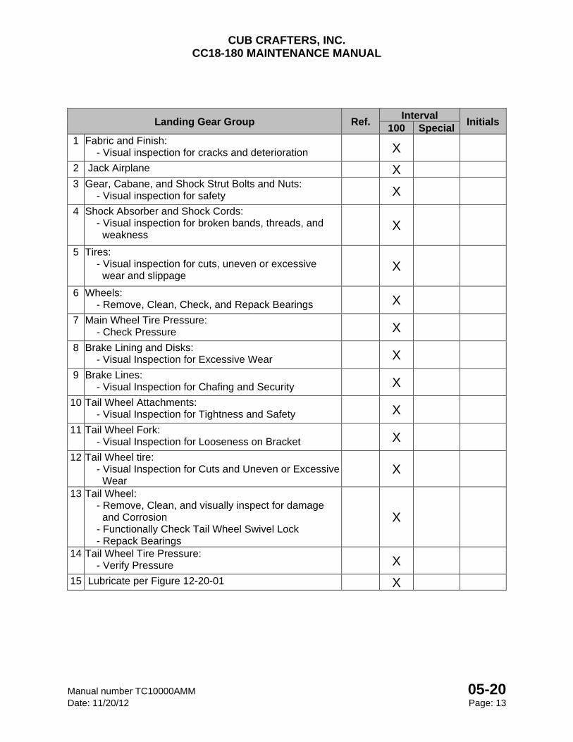
Landing Gear Group Ref. Interval
Initials 100 Special
1 Fabric and Finish: - Visual inspection for cracks and deterioration X
2 Jack Airplane X 3 Gear, Cabane, and Shock Strut Bolts and Nuts:
- Visual inspection for safety X
4 Shock Absorber and Shock Cords: - Visual inspection for broken bands, threads, and weakness
X
5 Tires: - Visual inspection for cuts, uneven or excessive wear and slippage
X
6 Wheels: - Remove, Clean, Check, and Repack Bearings X
7 Main Wheel Tire Pressure: - Check Pressure X
8 Brake Lining and Disks: - Visual Inspection for Excessive Wear X
9 Brake Lines: - Visual Inspection for Chafing and Security X
10 Tail Wheel Attachments: - Visual Inspection for Tightness and Safety X
11 Tail Wheel Fork: - Visual Inspection for Looseness on Bracket X
12 Tail Wheel tire: - Visual Inspection for Cuts and Uneven or Excessive Wear
X
13 Tail Wheel: - Remove, Clean, and visually inspect for damage and Corrosion - Functionally Check Tail Wheel Swivel Lock - Repack Bearings
X
14 Tail Wheel Tire Pressure: - Verify Pressure X
15 Lubricate per Figure 12-20-01 X
CUB CRAFTERS, INC. CC18-180 MAINTENANCE MANUAL
05-20 Manual number TC10000AMM Page: 14 Date: 11/20/12
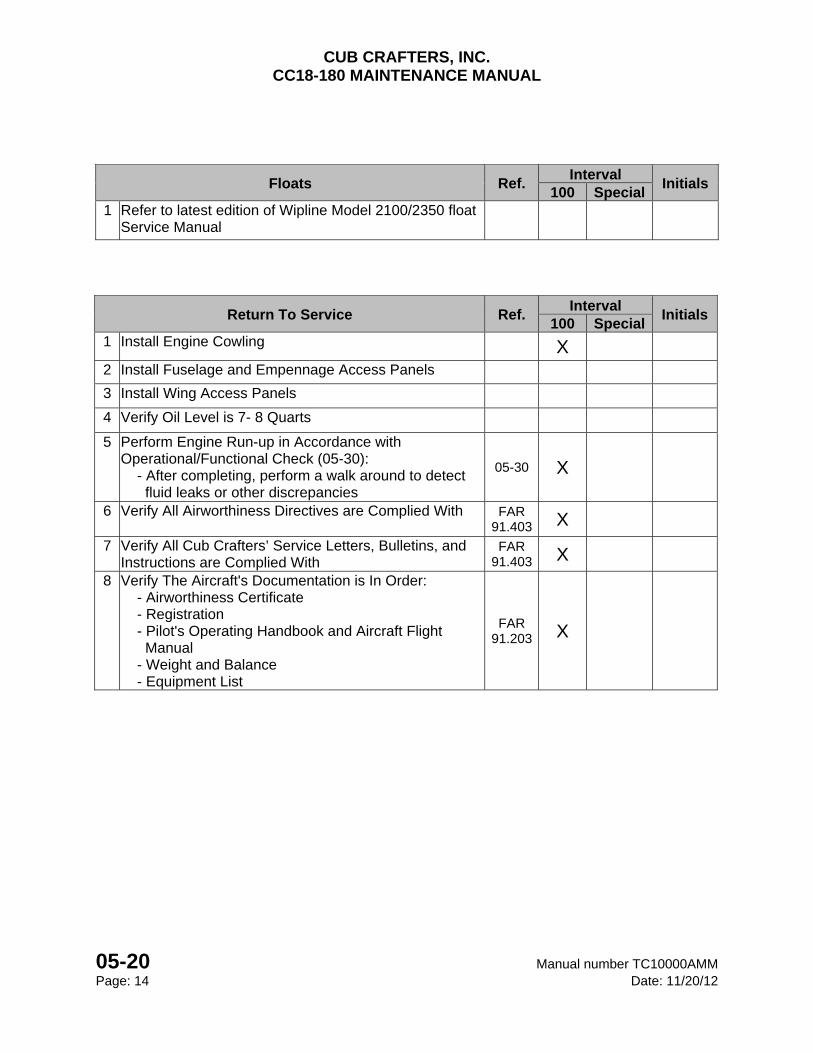
Floats Ref. Interval
Initials 100 Special
1 Refer to latest edition of Wipline Model 2100/2350 float Service Manual
Return To Service Ref.
Interval Initials
100 Special 1 Install Engine Cowling X
2 Install Fuselage and Empennage Access Panels
3 Install Wing Access Panels
4 Verify Oil Level is 7- 8 Quarts
5 BBBB Perform Engine Run-up in Accordance with Operational/Functional Check (05-30): - After completing, perform a walk around to detect fluid leaks or other discrepancies
05-30 X
6 Verify All Airworthiness Directives are Complied With FAR 91.403 X
7 Verify All Cub Crafters’ Service Letters, Bulletins, and Instructions are Complied With
FAR 91.403 X
8 Verify The Aircraft's Documentation is In Order: - Airworthiness Certificate - Registration - Pilot's Operating Handbook and Aircraft Flight Manual - Weight and Balance - Equipment List
FAR 91.203 X
CUB CRAFTERS, INC. CC18-180 MAINTENANCE MANUAL
Manual number TC10000AMM 05-30 Date: 9/21/05 Page: 1
05-30 OPERATIONAL AND FUNCTIONAL CHECK OF AIRCRAFT
TABLE OF CONTENTS 1 GENERAL ......................................................................................................................... 2
2 OPERATIONAL AND FUNCTIONAL CHECK................................................................... 2
CUB CRAFTERS, INC. CC18-180 MAINTENANCE MANUAL
05-30 Manual number TC10000AMM Page: 2 Date: 9/21/05
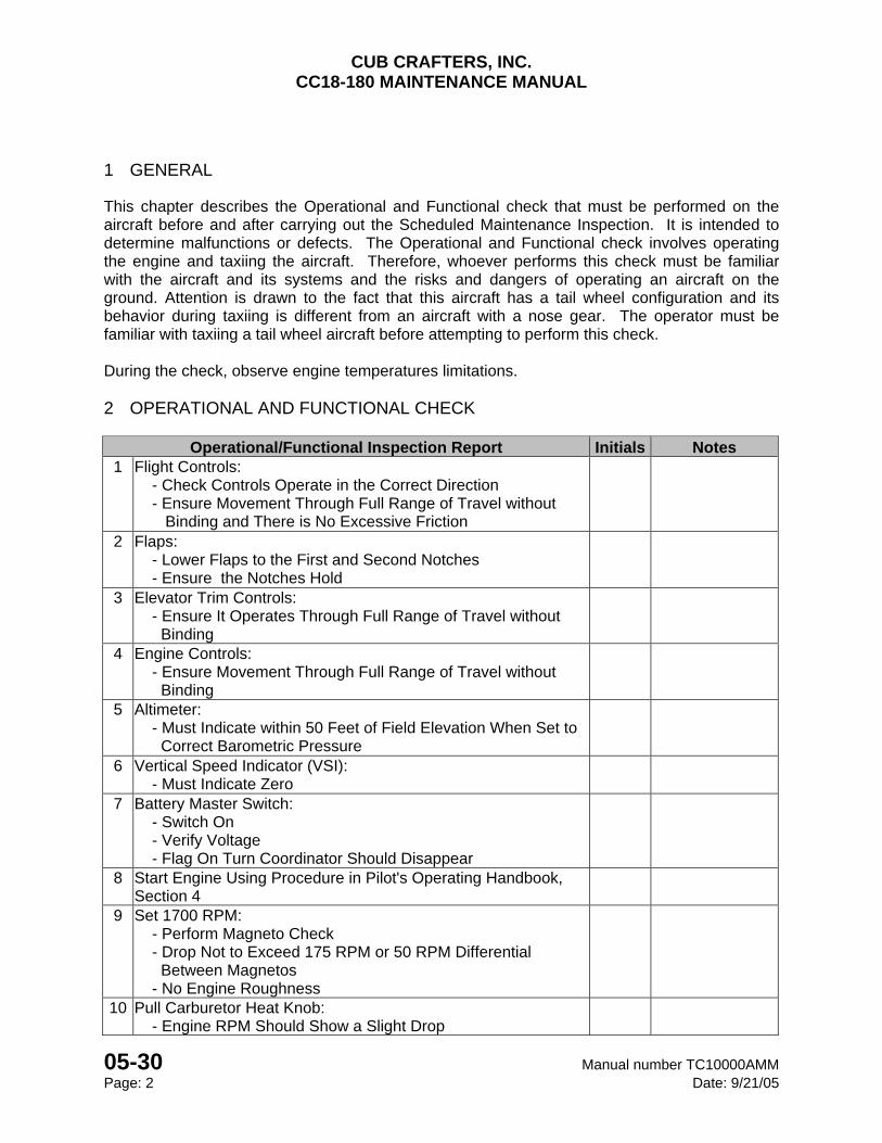
1 GENERAL
This chapter describes the Operational and Functional check that must be performed on the aircraft before and after carrying out the Scheduled Maintenance Inspection. It is intended to determine malfunctions or defects. The Operational and Functional check involves operating the engine and taxiing the aircraft. Therefore, whoever performs this check must be familiar with the aircraft and its systems and the risks and dangers of operating an aircraft on the ground. Attention is drawn to the fact that this aircraft has a tail wheel configuration and its behavior during taxiing is different from an aircraft with a nose gear. The operator must be familiar with taxiing a tail wheel aircraft before attempting to perform this check. During the check, observe engine temperatures limitations. 2 OPERATIONAL AND FUNCTIONAL CHECK
Operational/Functional Inspection Report Initials Notes
1 Flight Controls: - Check Controls Operate in the Correct Direction - Ensure Movement Through Full Range of Travel without Binding and There is No Excessive Friction
2 Flaps: - Lower Flaps to the First and Second Notches - Ensure the Notches Hold
3 Elevator Trim Controls: - Ensure It Operates Through Full Range of Travel without Binding
4 Engine Controls: - Ensure Movement Through Full Range of Travel without Binding
5 Altimeter: - Must Indicate within 50 Feet of Field Elevation When Set to Correct Barometric Pressure
6 Vertical Speed Indicator (VSI): - Must Indicate Zero
7 Battery Master Switch: - Switch On - Verify Voltage - Flag On Turn Coordinator Should Disappear
8 Start Engine Using Procedure in Pilot's Operating Handbook, Section 4
9 Set 1700 RPM: - Perform Magneto Check - Drop Not to Exceed 175 RPM or 50 RPM Differential Between Magnetos - No Engine Roughness
10 Pull Carburetor Heat Knob: - Engine RPM Should Show a Slight Drop
CUB CRAFTERS, INC. CC18-180 MAINTENANCE MANUAL
Manual number TC10000AMM 05-30 Date: 9/21/05 Page: 3
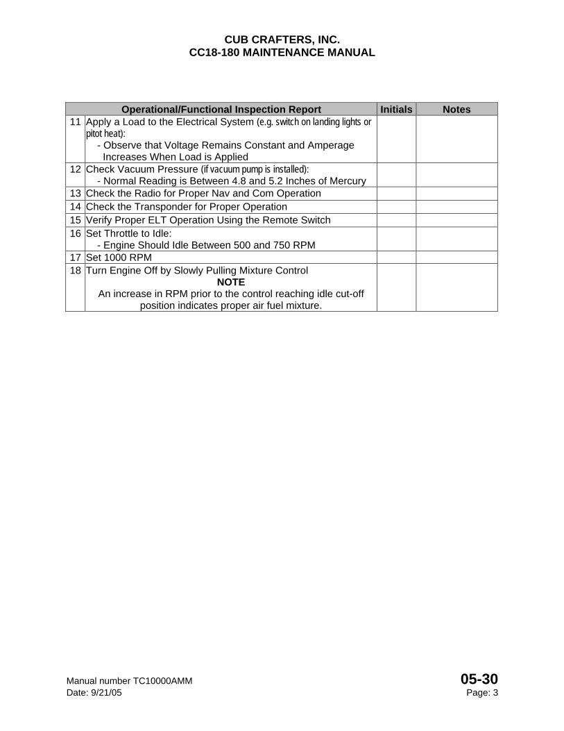
Operational/Functional Inspection Report Initials Notes 11 Apply a Load to the Electrical System (e.g. switch on landing lights or
pitot heat): - Observe that Voltage Remains Constant and Amperage Increases When Load is Applied
12 Check Vacuum Pressure (if vacuum pump is installed): - Normal Reading is Between 4.8 and 5.2 Inches of Mercury
13 Check the Radio for Proper Nav and Com Operation 14 Check the Transponder for Proper Operation 15 Verify Proper ELT Operation Using the Remote Switch 16 Set Throttle to Idle:
- Engine Should Idle Between 500 and 750 RPM 17 Set 1000 RPM 18 Turn Engine Off by Slowly Pulling Mixture Control
NOTE An increase in RPM prior to the control reaching idle cut-off
position indicates proper air fuel mixture.
CUB CRAFTERS, INC. CC18-180 MAINTENANCE MANUAL
05-30 Manual number TC10000AMM Page: 4 Date: 9/21/05
INTENTIONALLY LEFT BLANK

CHAPTER
06-00
AREAS, DIMENSIONS, AND
GEOMETRY

CUB CRAFTERS, INC. CC18-180 MAINTENANCE MANUAL
Manual number TC10000 06-00 Date: 11/20/12 Page: 1
06-00 AREAS, DIMENSIONS, AND GEOMETRY
TABLE OF CONTENTS
1 GENERAL ............................................................................................................................. 2 2 MAIN DIMENSIONS ............................................................................................................. 6
2.1 LANDPLANE ................................................................ Error! Bookmark not defined. 2.2 WIPAIRE 2100A AMPHIBIOUS FLOATS ..................................................................... 6 2.3 WIPAIRE 2100S SEAPLANE FLOATS ........................................................................ 6
3 WINGS .................................................................................................................................. 6 4 AILERONS ............................................................................................................................ 6 5 FLAPS ................................................................................................................................... 6 6 STABILIZER .......................................................................................................................... 6 7 FIN AND RUDDER ............................................................................................................... 7 8 LANDING GEAR ................................................................................................................... 7
8.1 LANDPLANE ................................................................................................................ 7 8.2 WIPAIRE 2100A AMPHIBIOUS FLOATS ..................................................................... 7
9 CONTROL SURFACE TRAVELS AND CABLE TENSION SETTINGS ................................ 7 9.1 AILERON ...................................................................................................................... 7 9.2 FLAPS .......................................................................................................................... 7 9.3 STABILIZERS ............................................................................................................... 7 9.4 ELEVATORS ................................................................................................................ 7 9.5 RUDDER ...................................................................................................................... 7
CUB CRAFTERS, INC. CC18-180 MAINTENANCE MANUAL
06-00 Manual number TC10000AMM Page: 2 Date: 11/20/12
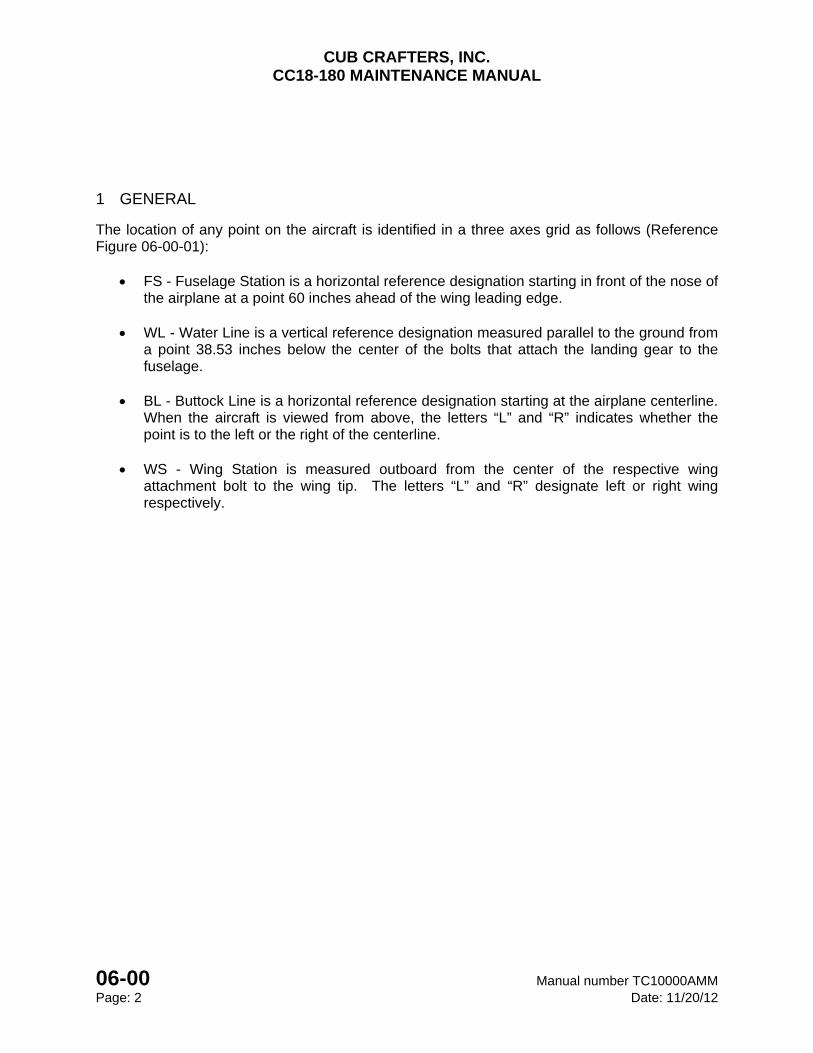
1 GENERAL
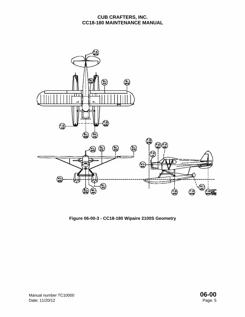
The location of any point on the aircraft is identified in a three axes grid as follows (Reference Figure 06-00-01):
FS - Fuselage Station is a horizontal reference designation starting in front of the nose of the airplane at a point 60 inches ahead of the wing leading edge.
WL - Water Line is a vertical reference designation measured parallel to the ground from
a point 38.53 inches below the center of the bolts that attach the landing gear to the fuselage.
BL - Buttock Line is a horizontal reference designation starting at the airplane centerline.
When the aircraft is viewed from above, the letters “L” and “R” indicates whether the point is to the left or the right of the centerline.
WS - Wing Station is measured outboard from the center of the respective wing
attachment bolt to the wing tip. The letters “L” and “R” designate left or right wing respectively.
CUB CRAFTERS, INC. CC18-180 MAINTENANCE MANUAL
Manual number TC10000 06-00 Date: 11/20/12 Page: 3
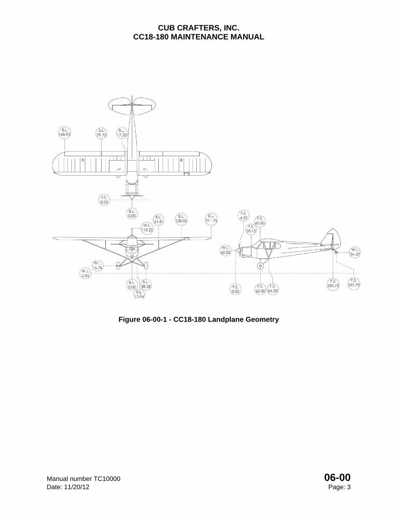
Figure 06-00-1 - CC18-180 Landplane Geometry
CUB CRAFTERS, INC. CC18-180 MAINTENANCE MANUAL
06-00 Manual number TC10000AMM Page: 4 Date: 11/20/12
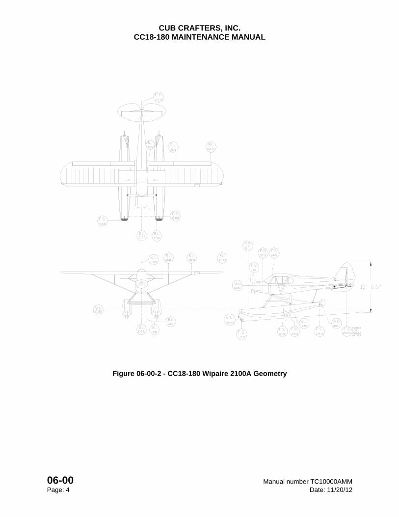
Figure 06-00-2 - CC18-180 Wipaire 2100A Geometry
CUB CRAFTERS, INC. CC18-180 MAINTENANCE MANUAL
Manual number TC10000 06-00 Date: 11/20/12 Page: 5
Figure 06-00-3 - CC18-180 Wipaire 2100S Geometry
CUB CRAFTERS, INC. CC18-180 MAINTENANCE MANUAL
06-00 Manual number TC10000AMM Page: 6 Date: 11/20/12
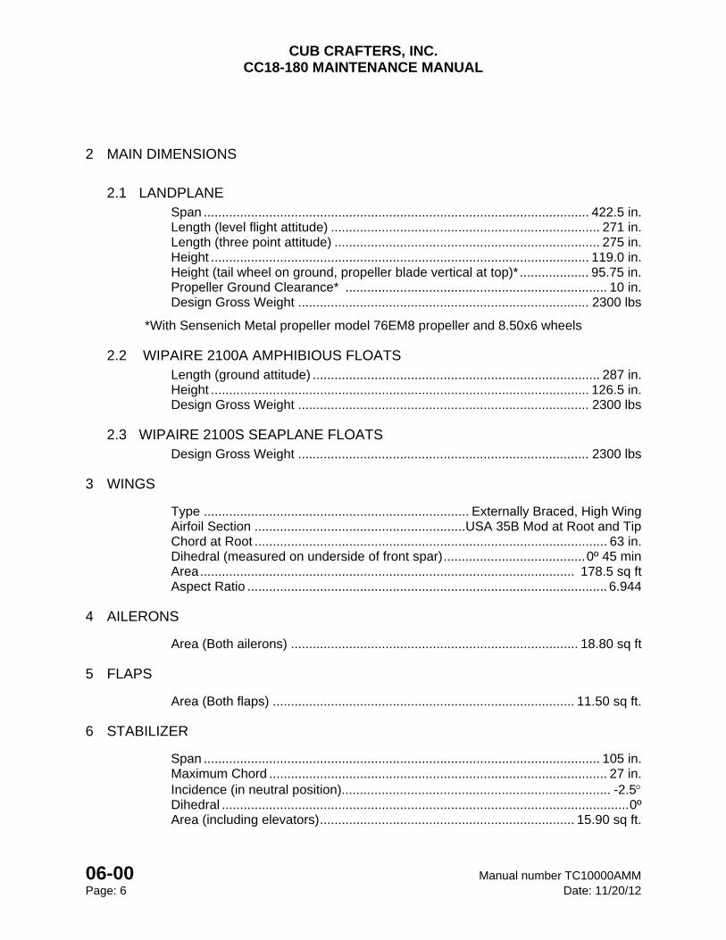
2 MAIN DIMENSIONS
2.1 LANDPLANE Span .......................................................................................................... 422.5 in. Length (level flight attitude) .......................................................................... 271 in. Length (three point attitude) ......................................................................... 275 in. Height ........................................................................................................ 119.0 in. Height (tail wheel on ground, propeller blade vertical at top)* ................... 95.75 in. Propeller Ground Clearance* ........................................................................ 10 in. Design Gross Weight ................................................................................ 2300 lbs
*With Sensenich Metal propeller model 76EM8 propeller and 8.50x6 wheels
2.2 WIPAIRE 2100A AMPHIBIOUS FLOATS Length (ground attitude) ............................................................................... 287 in. Height ........................................................................................................ 126.5 in. Design Gross Weight ................................................................................ 2300 lbs
2.3 WIPAIRE 2100S SEAPLANE FLOATS Design Gross Weight ................................................................................ 2300 lbs
3 WINGS
Type ......................................................................... Externally Braced, High Wing Airfoil Section .......................................................... USA 35B Mod at Root and Tip Chord at Root ................................................................................................. 63 in. Dihedral (measured on underside of front spar) ....................................... 0º 45 min Area ....................................................................................................... 178.5 sq ft Aspect Ratio ................................................................................................... 6.944
4 AILERONS
Area (Both ailerons) ............................................................................... 18.80 sq ft
5 FLAPS
Area (Both flaps) ................................................................................... 11.50 sq ft.
6 STABILIZER
Span ............................................................................................................. 105 in. Maximum Chord ............................................................................................. 27 in. Incidence (in neutral position).......................................................................... -2.5 Dihedral ................................................................................................................ 0º Area (including elevators) ...................................................................... 15.90 sq ft.
CUB CRAFTERS, INC. CC18-180 MAINTENANCE MANUAL
Manual number TC10000 06-00 Date: 11/20/12 Page: 7
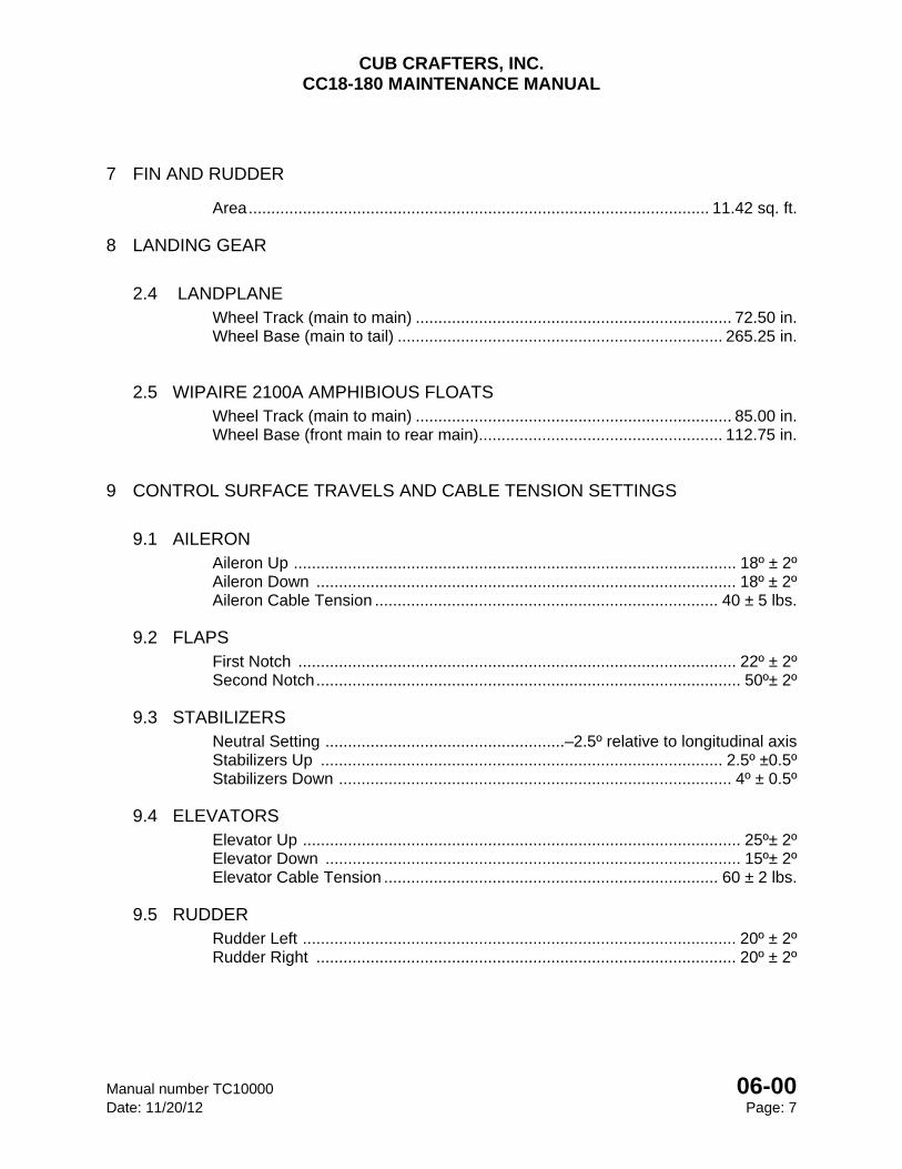
7 FIN AND RUDDER
Area ...................................................................................................... 11.42 sq. ft.
8 LANDING GEAR
2.4 LANDPLANE Wheel Track (main to main) ...................................................................... 72.50 in. Wheel Base (main to tail) ........................................................................ 265.25 in.
2.5 WIPAIRE 2100A AMPHIBIOUS FLOATS Wheel Track (main to main) ...................................................................... 85.00 in. Wheel Base (front main to rear main) ...................................................... 112.75 in.
9 CONTROL SURFACE TRAVELS AND CABLE TENSION SETTINGS
9.1 AILERON Aileron Up .................................................................................................. 18º ± 2º Aileron Down ............................................................................................. 18º ± 2º Aileron Cable Tension ............................................................................ 40 ± 5 lbs.
9.2 FLAPS First Notch ................................................................................................. 22º ± 2º Second Notch .............................................................................................. 50º± 2º
9.3 STABILIZERS Neutral Setting .....................................................–2.5º relative to longitudinal axis Stabilizers Up ......................................................................................... 2.5º ±0.5º Stabilizers Down ....................................................................................... 4º ± 0.5º
9.4 ELEVATORS Elevator Up ................................................................................................. 25º± 2º Elevator Down ............................................................................................ 15º± 2º Elevator Cable Tension .......................................................................... 60 ± 2 lbs.
9.5 RUDDER Rudder Left ................................................................................................ 20º ± 2º Rudder Right ............................................................................................. 20º ± 2º

CUB CRAFTERS, INC. CC18-180 MAINTENANCE MANUAL
06-00 Manual number TC10000AMM Page: 8 Date: 11/20/12
INTENTIONALLY LEFT BLANK

CHAPTER
07-00
JACKING AND LIFTING

CUB CRAFTERS, INC. CC18-180 MAINTENANCE MANUAL
Manual number TC10000AMM 07-00 Date: 6/30/14 Page: 1
07-00 JACKING AND LIFTING TABLE OF CONTENTS 1. GENERAL ............................................................................................................................. 2
2. MAINTENANCE PRACTICES .............................................................................................. 2
2.1 JACKING THE AIRPLANE ............................................................................................... 2
2.1.1 TOOLS, EQUIPMENT AND SUPPLIES ..................................................................... 2
2.1.2 RAISING THE TAIL ..................................................................................................... 2
2.1.3 RAISING THE AIRCRAFT FROM THE LANDING GEAR .......................................... 3
2.1.4 RAISING THE AIRCRAFT FROM THE WING ............................................................ 4
CUB CRAFTERS, INC. CC18-180 MAINTENANCE MANUAL
07-00 Manual number TC10000AMM Page: 2 Date: 6/30/14
1 GENERAL
This section will describe the methods for jacking the CC18-180.
2 MAINTENANCE PRACTICES
2.1 JACKING THE AIRPLANE
2.1.1 TOOLS, EQUIPMENT AND SUPPLIES
Description P/N or Spec. Supplier Purpose
Floor Jack - Any Source Jack Main Wheels Wooden Saw Horse or Bench - Any Source Place Under Tail Cub Crafters’ Wing Jack - Any Source Jack From Wing
CAUTION Do not jack the aircraft outside or in open hanger with winds in excess of 10 m.p.h.
NOTE Raise airplane no more than required for maintenance being performed.
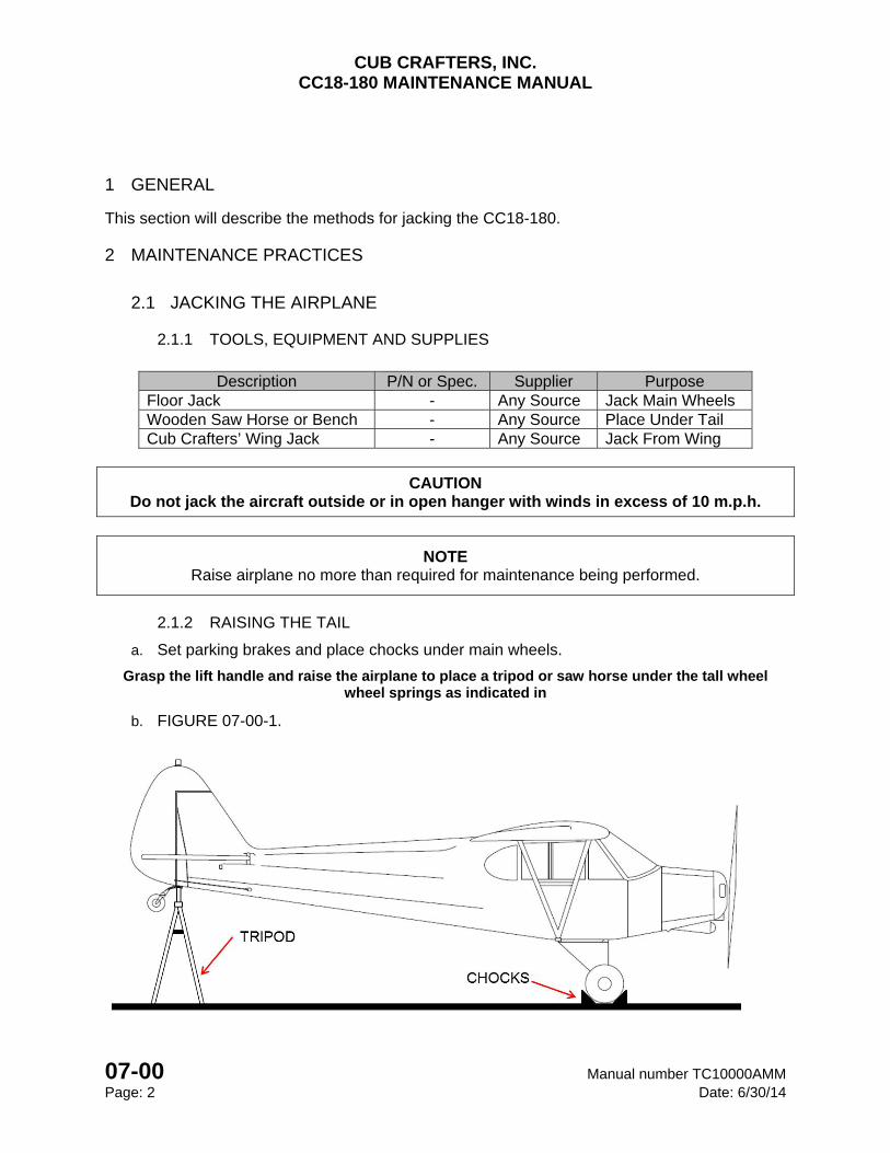
2.1.2 RAISING THE TAIL
a. Set parking brakes and place chocks under main wheels.
Grasp the lift handle and raise the airplane to place a tripod or saw horse under the tall wheel wheel springs as indicated in
b. FIGURE 07-00-1.
CUB CRAFTERS, INC. CC18-180 MAINTENANCE MANUAL
Manual number TC10000AMM 07-00 Date: 6/30/14 Page: 3
FIGURE 07-00-1 - Raising the Tail
CUB CRAFTERS, INC. CC18-180 MAINTENANCE MANUAL
07-00 Manual number TC10000AMM Page: 4 Date: 6/30/14
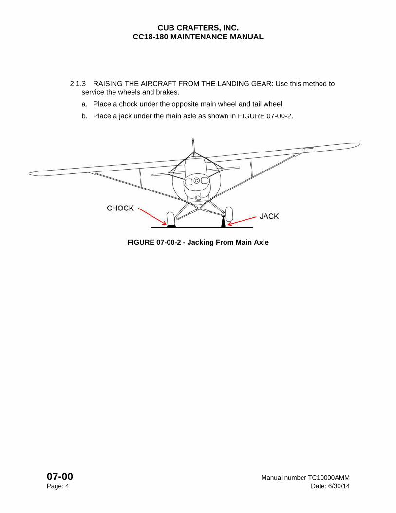
2.1.3 RAISING THE AIRCRAFT FROM THE LANDING GEAR: Use this method to service the wheels and brakes.
a. Place a chock under the opposite main wheel and tail wheel.
b. Place a jack under the main axle as shown in FIGURE 07-00-2.
FIGURE 07-00-2 - Jacking From Main Axle
CUB CRAFTERS, INC. CC18-180 MAINTENANCE MANUAL
07-00 Manual number TC10000AMM Page: 5 Date: 6/30/14
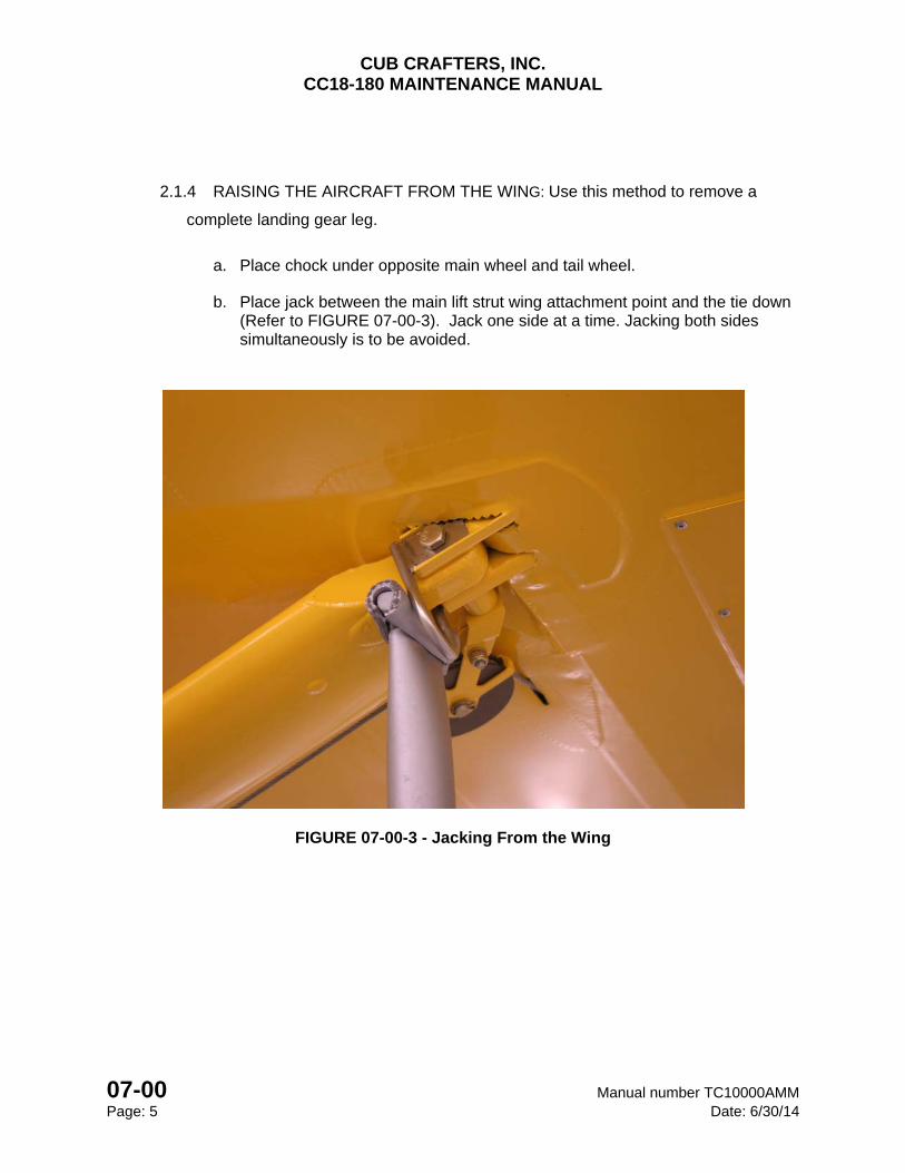
2.1.4 RAISING THE AIRCRAFT FROM THE WING: Use this method to remove a
complete landing gear leg.
a. Place chock under opposite main wheel and tail wheel.
b. Place jack between the main lift strut wing attachment point and the tie down (Refer to FIGURE 07-00-3). Jack one side at a time. Jacking both sides simultaneously is to be avoided.
FIGURE 07-00-3 - Jacking From the Wing

CHAPTER
08-00
LEVELING AND WEIGHING

CUB CRAFTERS, INC. CC18-180 MAINTENANCE MANUAL
Manual number TC10000AMM 08-00 Date: 6/30/14 Page: 1
08-00 LEVELING AND WEIGHING TABLE OF CONTENTS 1 LEVELING ............................................................................................................................. 2
1.1 MAINTENANCE PRACTICES FOR LANDPLANE AIRCRAFT .................................... 2
1.1.1 PREPARATION ......................................................................................................... 2
1.1.2 LONGITUDINAL LEVELING ..................................................................................... 2
1.1.3 LATERAL LEVELING ................................................................................................ 2
1.2 MAINTENANCE PRACTICES FOR AIRCRAFT EQUIPPED WITH WIPAIRE 2100A AMPHIBIOUS FLOATS ........................................................................................... 4
1.2.1 PREPARATION ......................................................................................................... 4
1.2.2 LONGITUDINAL LEVELING ..................................................................................... 5
1.2.3 LATERAL LEVELING ................................................................................................ 5
2 WEIGHING ............................................................................................................................ 5
2.1 GENERAL .............................................................................................................. 5
2.2 MAINTENANCE PRACTICES FOR LANDPLANE AIRCRAFT .................................... 6
2.2.1 PREPARATION ......................................................................................................... 6
2.2.2 WEIGHING THE AIRCRAFT ..................................................................................... 6
2.3MAINTENANCE PRACTICES FOR AIRCRAFT EQUIPPED WITH WIPAIRE 2100A AMPHIBIOUS FLOATS ........................................... Error! Bookmark not defined.
2.3.1 PREPARATION ......................................................................................................... 8
2.3.2 WEIGHING THE AIRCRAFT ..................................................................................... 8
2.4 MAINTENANCE PRACTICES FOR AIRCRAFT EQUIPPED WITH WIPAIRE 2100S SEAPLANE FLOATS ............................................................................................ 10
2.4.1 CALCULATING EMPTY WEIGHT OF THE AIRCRAFT ......................................... 10
CUB CRAFTERS, INC. CC18-180 MAINTENANCE MANUAL
08-00 Manual number TC10000AMM Page: 2 Date: 6/30/14
1 LEVELING
1.1 MAINTENANCE PRACTICES FOR LANDPLANE AIRCRAFT
1.1.1 PREPARATION
a. Place the aircraft in a hangar with the doors closed where the wind will not affect the aircraft.
b. Place the aircraft approximately in a flight level attitude by supporting the tail wheel on a bench.
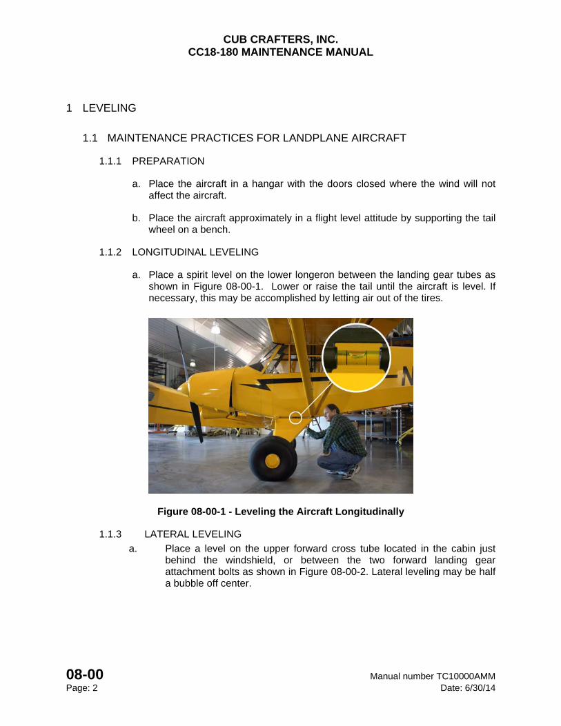
1.1.2 LONGITUDINAL LEVELING
a. Place a spirit level on the lower longeron between the landing gear tubes as shown in Figure 08-00-1. Lower or raise the tail until the aircraft is level. If necessary, this may be accomplished by letting air out of the tires.
Figure 08-00-1 - Leveling the Aircraft Longitudinally
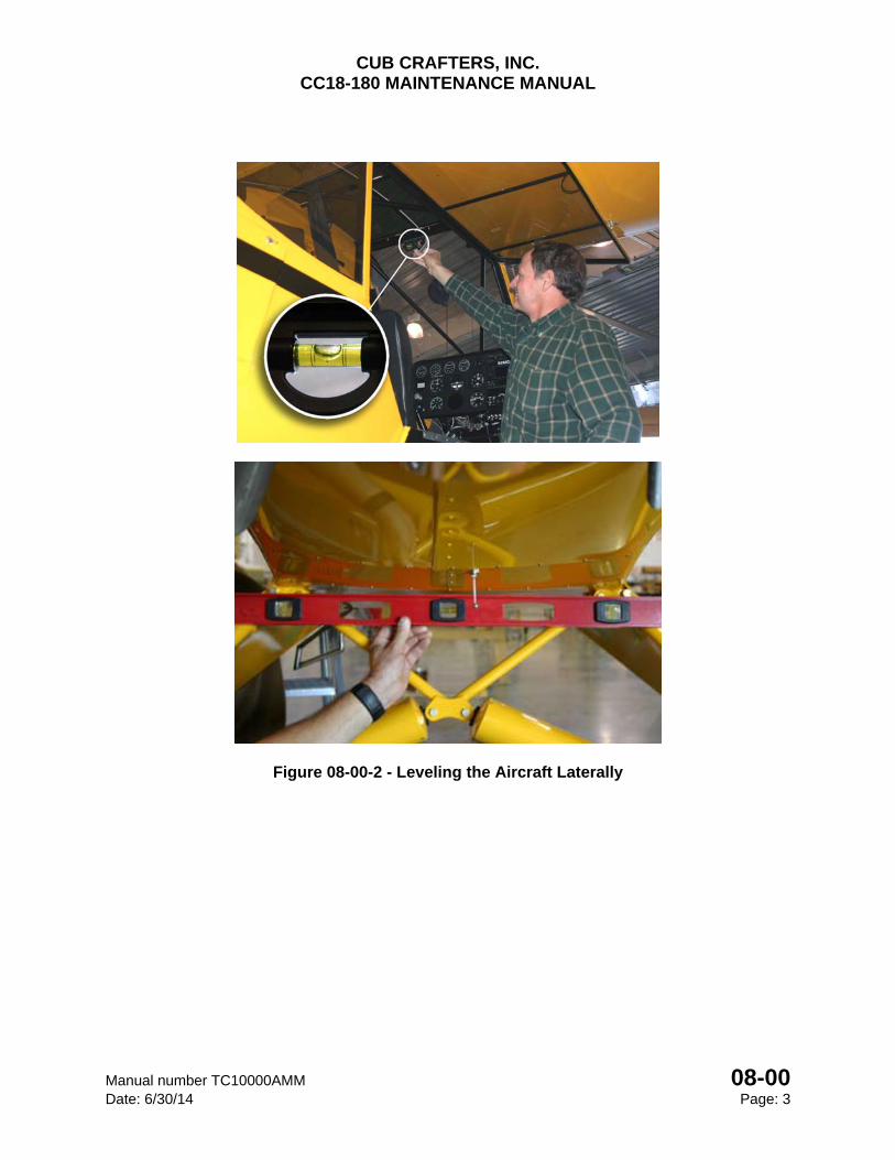
1.1.3 LATERAL LEVELING
a. Place a level on the upper forward cross tube located in the cabin just behind the windshield, or between the two forward landing gear attachment bolts as shown in Figure 08-00-2. Lateral leveling may be half a bubble off center.
CUB CRAFTERS, INC. CC18-180 MAINTENANCE MANUAL
Manual number TC10000AMM 08-00 Date: 6/30/14 Page: 3
Figure 08-00-2 - Leveling the Aircraft Laterally
CUB CRAFTERS, INC. CC18-180 MAINTENANCE MANUAL
08-00 Manual number TC10000AMM Page: 4 Date: 6/30/14
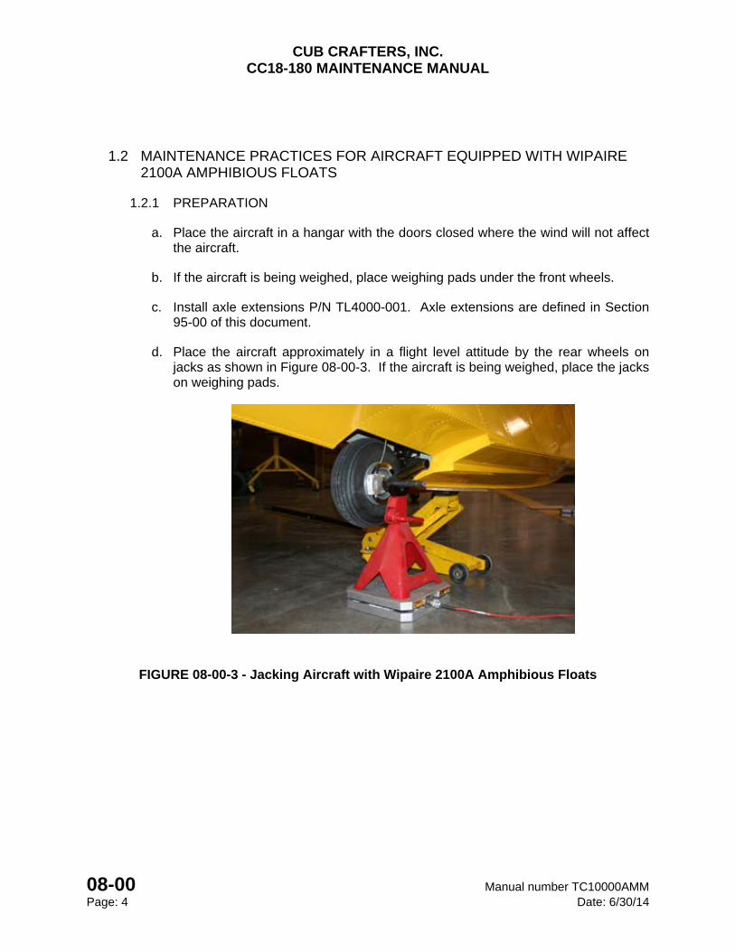
1.2 MAINTENANCE PRACTICES FOR AIRCRAFT EQUIPPED WITH WIPAIRE 2100A AMPHIBIOUS FLOATS
1.2.1 PREPARATION
a. Place the aircraft in a hangar with the doors closed where the wind will not affect the aircraft.
b. If the aircraft is being weighed, place weighing pads under the front wheels.
c. Install axle extensions P/N TL4000-001. Axle extensions are defined in Section 95-00 of this document.
d. Place the aircraft approximately in a flight level attitude by the rear wheels on jacks as shown in Figure 08-00-3. If the aircraft is being weighed, place the jacks on weighing pads.
FIGURE 08-00-3 - Jacking Aircraft with Wipaire 2100A Amphibious Floats
CUB CRAFTERS, INC. CC18-180 MAINTENANCE MANUAL
Manual number TC10000AMM 08-00 Date: 6/30/14 Page: 5
1.2.2 LONGITUDINAL LEVELING
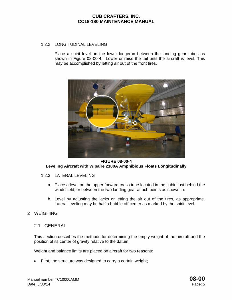
Place a spirit level on the lower longeron between the landing gear tubes as shown in Figure 08-00-4. Lower or raise the tail until the aircraft is level. This may be accomplished by letting air out of the front tires.
FIGURE 08-00-4
Leveling Aircraft with Wipaire 2100A Amphibious Floats Longitudinally
1.2.3 LATERAL LEVELING
a. Place a level on the upper forward cross tube located in the cabin just behind the windshield, or between the two landing gear attach points as shown in.
b. Level by adjusting the jacks or letting the air out of the tires, as appropriate. Lateral leveling may be half a bubble off center as marked by the spirit level.
2 WEIGHING
2.1 GENERAL
This section describes the methods for determining the empty weight of the aircraft and the position of its center of gravity relative to the datum.
Weight and balance limits are placed on aircraft for two reasons:
First, the structure was designed to carry a certain weight;
CUB CRAFTERS, INC. CC18-180 MAINTENANCE MANUAL
08-00 Manual number TC10000AMM Page: 6 Date: 6/30/14
Second, the operating weight of the aircraft and the position of the center of gravity affect performance, stability, and control characteristics, particularly in stall and spin recovery.
The aircraft will only attain the performance and exhibit the handling characteristics used for certification if it is flown when the weight and the center of gravity are within the approved range.
Prior to leaving the factory, the aircraft was weighed and the C.G. location was computed. You will find this information in paragraph 6.4 of the Pilot’s Operating Handbook and Aircraft Flight Manual. If it should become necessary to re-weigh the aircraft, follow the procedures given in this section.
2.2 MAINTENANCE PRACTICES FOR LANDPLANE AIRCRAFT
2.2.1 PREPARATION
a. Remove any items not listed on the Aircraft Equipment List (such as rags, charts, tools, etc.) The Aircraft Equipment List is found in Section 6 of the Pilot’s Operating Handbook and Aircraft Flight Manual
b. Clean the aircraft to remove excess dirt and grease.
c. Remove the fuel from the aircraft. This may be accomplished by opening the fuel drains until all remaining fuel is drained.
d. Check that the oil is full (8 quarts on the dip stick).
e. Position the pilot’s seat in the mid position.
f. Zero the scales or record the tare, as appropriate.
2.2.2 WEIGHING THE AIRCRAFT
a. Place the aircraft on calibrated scales. The range of the scales should be 1000 lb. for each main wheel and 250 lb. for the tail wheel.
b. Level the aircraft (Refer to Section 08-00 11.1).
c. Record the weight of the main wheels and the tail wheel in Figure 08-00-5.
CUB CRAFTERS, INC. CC18-180 MAINTENANCE MANUAL
Manual number TC10000AMM 08-00 Date: 6/30/14 Page: 7
Line Number Position
Recorded Weight Tare
Actual Weight Arm Moment
1 Left Main Wheel 62.50 in.
2 Right Main Wheel 62.50 in.
3 Tail Wheel 265.25 in.
TOTAL WEIGHT
(Weight in Lines 1+2+3)
TOTAL MOMENT (Moment in
Lines 1+2+3)
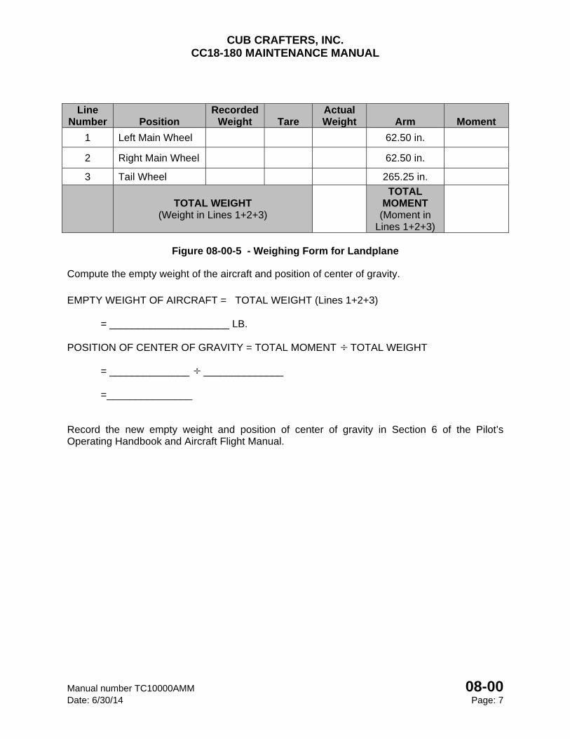
Figure 08-00-5 - Weighing Form for Landplane
Compute the empty weight of the aircraft and position of center of gravity.
EMPTY WEIGHT OF AIRCRAFT = TOTAL WEIGHT (Lines 1+2+3) = _____________________ LB. POSITION OF CENTER OF GRAVITY = TOTAL MOMENT TOTAL WEIGHT = ______________ ______________ =_______________
Record the new empty weight and position of center of gravity in Section 6 of the Pilot’s Operating Handbook and Aircraft Flight Manual.
CUB CRAFTERS, INC. CC18-180 MAINTENANCE MANUAL
08-00 Manual number TC10000AMM Page: 8 Date: 6/30/14
2.3 MAINTENANCE PRACTICES FOR AIRCRAFT EQUIPPED WITH WIPAIRE 2100 A AMPHIBIOUS FLOATS
2.3.1 PREPARATION
a. Remove any items not listed on the Aircraft Equipment List (such as rags, charts, tools, etc.) The Aircraft Equipment List is found in Section 6 of the Pilot’s Operating Handbook and Aircraft Flight Manual.
b. Clean the aircraft to remove excess dirt and grease.
c. Remove the fuel from the aircraft. This may be accomplished by opening the fuel drains until all remaining fuel is drained.
d. Check that the oil is full (8 quarts on the dip stick).
e. Position the pilot’s seat in the mid position.
f. Zero the scales or record the tare, as appropriate.
2.3.2 WEIGHING THE AIRCRAFT
a. Place the aircraft on calibrated scales. The range of the scales should be 1000 lb. for each main wheel.
b. Level the aircraft (Refer to Section 08-00-11.2).
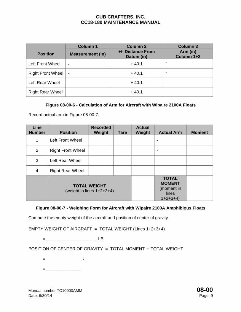
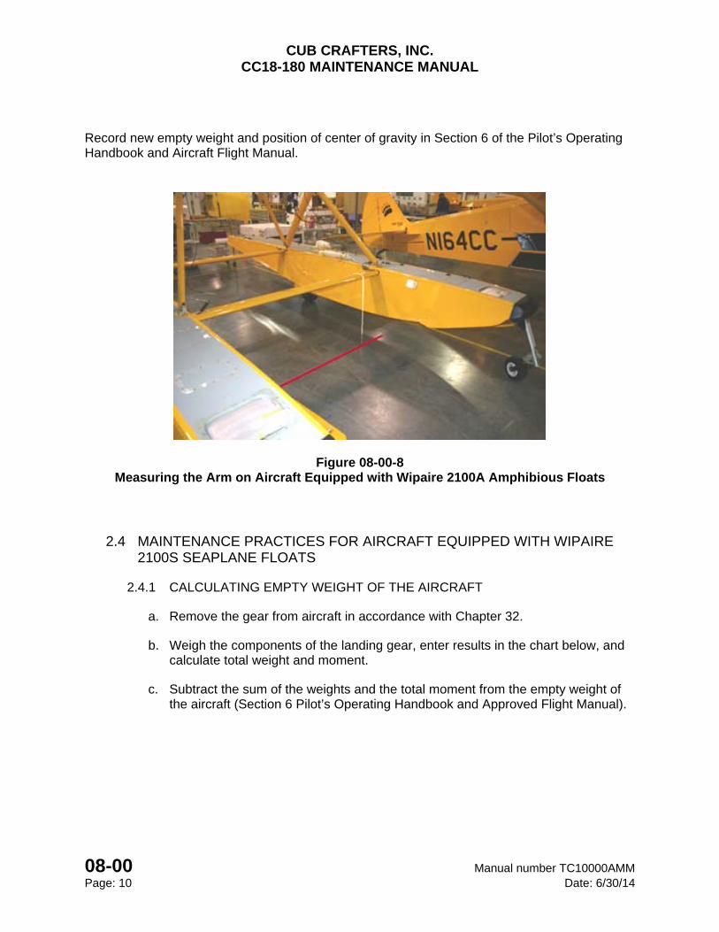
c. Measure the arm for the front and rear wheels. This is to be done by dropping a plumb bob off the left and right extremes of the leading edge of the forward float spreader bar and marking these locations on the floor. Draw a line on the floor between these points. Then, measure the longitudinal distance from each of the front and rear wheels to the line. The leading edge of the forward spreader bar is located at FS 40.1 (Figure 08-00-8). Record this information in Figure 08-00-6.
NOTE
The Left and Right front wheel measurements of the floats will be a negative number in Column 1 of Figure 08-00-6.
d. Record the weight of all four wheels in Figure 08-00-7.
CUB CRAFTERS, INC. CC18-180 MAINTENANCE MANUAL
Manual number TC10000AMM 08-00 Date: 6/30/14 Page: 9
Position
Column 1 Column 2 Column 3
Measurement (in) +/- Distance From
Datum (in) Arm (in)
Column 1+2
Left Front Wheel - + 40.1 -
Right Front Wheel - + 40.1 -
Left Rear Wheel + 40.1
Right Rear Wheel + 40.1
Figure 08-00-6 - Calculation of Arm for Aircraft with Wipaire 2100A Floats
Record actual arm in Figure 08-00-7.
Figure 08-00-7 - Weighing Form for Aircraft with Wipaire 2100A Amphibious Floats
Compute the empty weight of the aircraft and position of center of gravity.
EMPTY WEIGHT OF AIRCRAFT = TOTAL WEIGHT (Lines 1+2+3+4) = _____________________ LB. POSITION OF CENTER OF GRAVITY = TOTAL MOMENT TOTAL WEIGHT = ______________ ______________ =_______________
Line Number Position
Recorded Weight Tare
Actual Weight Actual Arm Moment
1 Left Front Wheel -
2 Right Front Wheel -
3 Left Rear Wheel
4 Right Rear Wheel
TOTAL WEIGHT (weight in lines 1+2+3+4)
TOTAL MOMENT (moment in
lines 1+2+3+4)
CUB CRAFTERS, INC. CC18-180 MAINTENANCE MANUAL
08-00 Manual number TC10000AMM Page: 10 Date: 6/30/14
Record new empty weight and position of center of gravity in Section 6 of the Pilot’s Operating Handbook and Aircraft Flight Manual.
Figure 08-00-8 Measuring the Arm on Aircraft Equipped with Wipaire 2100A Amphibious Floats
2.4 MAINTENANCE PRACTICES FOR AIRCRAFT EQUIPPED WITH WIPAIRE 2100S SEAPLANE FLOATS
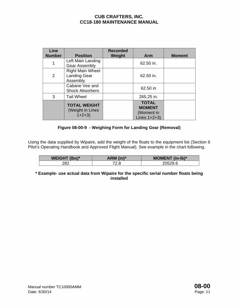
2.4.1 CALCULATING EMPTY WEIGHT OF THE AIRCRAFT
a. Remove the gear from aircraft in accordance with Chapter 32.
b. Weigh the components of the landing gear, enter results in the chart below, and calculate total weight and moment.
c. Subtract the sum of the weights and the total moment from the empty weight of the aircraft (Section 6 Pilot’s Operating Handbook and Approved Flight Manual).
CUB CRAFTERS, INC. CC18-180 MAINTENANCE MANUAL
Manual number TC10000AMM 08-00 Date: 6/30/14 Page: 11
Line
Number Position Recorded
Weight Arm Moment
1 Left Main Landing Gear Assembly
62.50 in.
2 Right Main Wheel Landing Gear Assembly
62.50 in.
Cabane Vee and Shock Absorbers
62.50 in
3 Tail Wheel 265.25 in.
TOTAL WEIGHT (Weight in Lines
1+2+3)
TOTAL MOMENT
(Moment in Lines 1+2+3)
Figure 08-00-9 - Weighing Form for Landing Gear (Removal)
Using the data supplied by Wipaire, add the weight of the floats to the equipment list (Section 6 Pilot’s Operating Handbook and Approved Flight Manual). See example in the chart following.
WEIGHT (lbs)* ARM (in)* MOMENT (in-lb)*
282 72.8 20529.6
* Example- use actual data from Wipaire for the specific serial number floats being installed
CUB CRAFTERS, INC. CC18-180 MAINTENANCE MANUAL
08-00 Manual number TC10000AMM Page: 12 Date: 6/30/14
INTENTIONALLY LEFT BLANK
CHAPTER
10-00
PARKING AND MOORING

CUB CRAFTERS, INC. CC18-180 MAINTENANCE MANUAL
Manual number TC10000AMM 10-00 Date: 05/20/08 Page: 1
10-00 PARKING AND MOORING TABLE OF CONTENTS 1. PARKING .............................................................................................................................. 2
2. MOORING ............................................................................................................................. 2
3. STORAGE ............................................................................................................................. 3
A. GENERAL ......................................................................................................................... 3
B. MAINTENANCE PRACTICES .......................................................................................... 3
(1) TEMPORARY STORAGE - 30 to 90 Days ................................................................. 3
(2) INDEFINITE STORAGE .............................................................................................. 5
(3) PREPARATION FOR SERVICE ................................................................................. 4
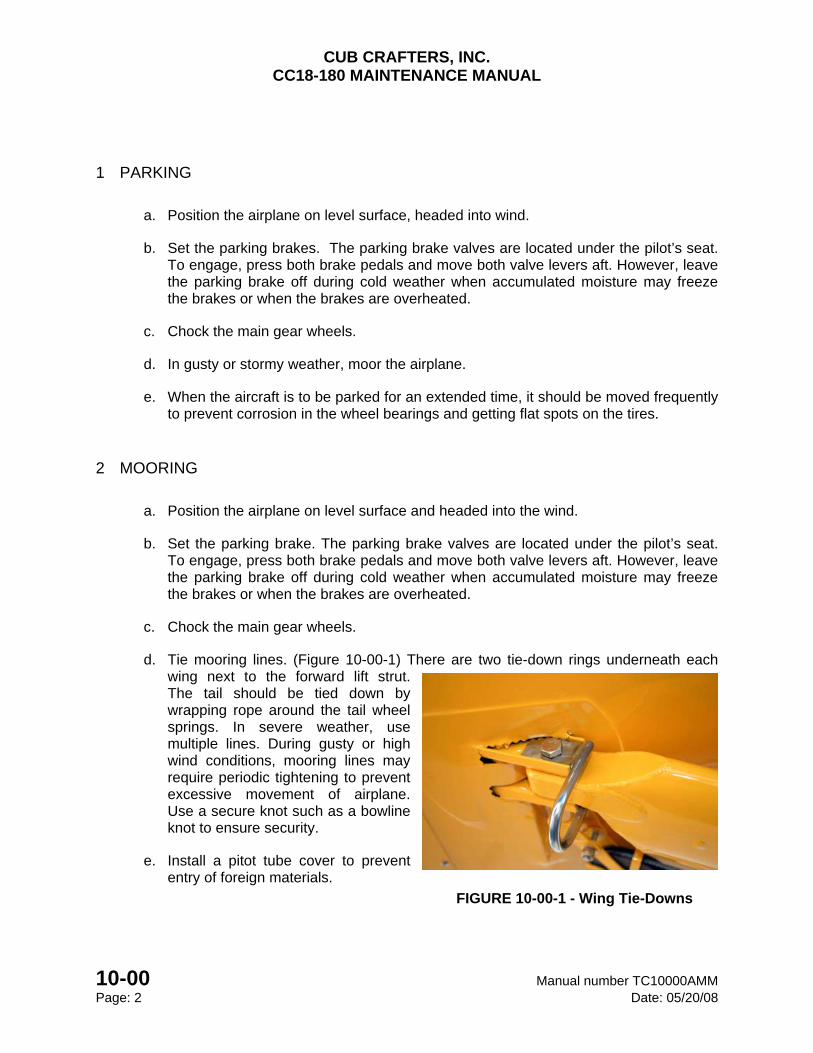
CUB CRAFTERS, INC. CC18-180 MAINTENANCE MANUAL
10-00 Manual number TC10000AMM Page: 2 Date: 05/20/08
1 PARKING
a. Position the airplane on level surface, headed into wind.
b. Set the parking brakes. The parking brake valves are located under the pilot’s seat. To engage, press both brake pedals and move both valve levers aft. However, leave the parking brake off during cold weather when accumulated moisture may freeze the brakes or when the brakes are overheated.
c. Chock the main gear wheels.
d. In gusty or stormy weather, moor the airplane.
e. When the aircraft is to be parked for an extended time, it should be moved frequently to prevent corrosion in the wheel bearings and getting flat spots on the tires.
2 MOORING
a. Position the airplane on level surface and headed into the wind.
b. Set the parking brake. The parking brake valves are located under the pilot’s seat. To engage, press both brake pedals and move both valve levers aft. However, leave the parking brake off during cold weather when accumulated moisture may freeze the brakes or when the brakes are overheated.
c. Chock the main gear wheels.
d. Tie mooring lines. (Figure 10-00-1) There are two tie-down rings underneath each wing next to the forward lift strut. The tail should be tied down by wrapping rope around the tail wheel springs. In severe weather, use multiple lines. During gusty or high wind conditions, mooring lines may require periodic tightening to prevent excessive movement of airplane. Use a secure knot such as a bowline knot to ensure security.
e. Install a pitot tube cover to prevent entry of foreign materials.
FIGURE 10-00-1 - Wing Tie-Downs
CUB CRAFTERS, INC. CC18-180 MAINTENANCE MANUAL
Manual number TC10000AMM 10-00 Date: 05/20/08 Page: 3
3 STORAGE
3.1 GENERAL
The procedures outlined in this chapter must be followed if it is expected that the aircraft will remain inactive for longer than 30 days.
3.2 MAINTENANCE PRACTICES
3.2.1 TEMPORARY STORAGE - 30 to 90 Days
a. Park and moor the airplane.
b. Apply engine preservation. Refer to the latest edition of Textron Lycoming Service Letter SL L180.
c. Fill the fuel tanks completely. Check for water accumulation each week.
d. Wipe the tires with dry cloth, and treat them with tire protector spray. Mark the tire positions and date with chalk. Turn the wheels and check air pressure regularly.
e. Remove the battery (Refer to 24-00) and ELT battery (Refer to 05-10) and store in accordance with standard practices. Clean the battery compartment and the battery cable terminals to neutralize any battery acid that may be present.
f. Lubricate according to lubrication schedule. (Refer to 12-20)
g. Clean the propeller in accordance with propeller’s manufacturer’s instructions to remove dirt, oil, and bug accumulation.
h. Clean and cover the instruments and panel. Observe any additional precautions recommended by the various manufacturers of the avionics and the instruments.
i. Clean and install protective covers on the seats.
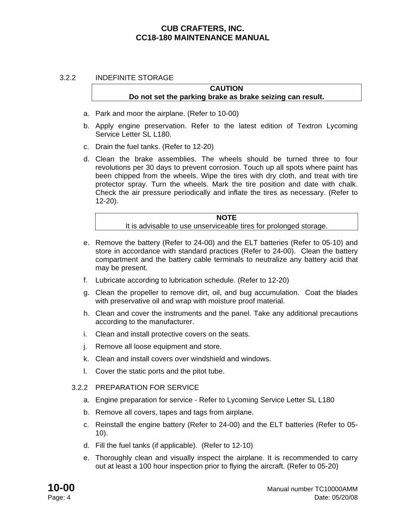
CUB CRAFTERS, INC. CC18-180 MAINTENANCE MANUAL
10-00 Manual number TC10000AMM Page: 4 Date: 05/20/08
3.2.2 INDEFINITE STORAGE
CAUTION Do not set the parking brake as brake seizing can result.
a. Park and moor the airplane. (Refer to 10-00)
b. Apply engine preservation. Refer to the latest edition of Textron Lycoming Service Letter SL L180.
c. Drain the fuel tanks. (Refer to 12-20)
d. Clean the brake assemblies. The wheels should be turned three to four revolutions per 30 days to prevent corrosion. Touch up all spots where paint has been chipped from the wheels. Wipe the tires with dry cloth, and treat with tire protector spray. Turn the wheels. Mark the tire position and date with chalk. Check the air pressure periodically and inflate the tires as necessary. (Refer to 12-20).
NOTE It is advisable to use unserviceable tires for prolonged storage.
e. Remove the battery (Refer to 24-00) and the ELT batteries (Refer to 05-10) and store in accordance with standard practices (Refer to 24-00). Clean the battery compartment and the battery cable terminals to neutralize any battery acid that may be present.
f. Lubricate according to lubrication schedule. (Refer to 12-20)
g. Clean the propeller to remove dirt, oil, and bug accumulation. Coat the blades with preservative oil and wrap with moisture proof material.
h. Clean and cover the instruments and the panel. Take any additional precautions according to the manufacturer.
i. Clean and install protective covers on the seats.
j. Remove all loose equipment and store.
k. Clean and install covers over windshield and windows.
l. Cover the static ports and the pitot tube.
3.2.2 PREPARATION FOR SERVICE
a. Engine preparation for service - Refer to Lycoming Service Letter SL L180
b. Remove all covers, tapes and tags from airplane.
c. Reinstall the engine battery (Refer to 24-00) and the ELT batteries (Refer to 05-10).
d. Fill the fuel tanks (if applicable). (Refer to 12-10)
e. Thoroughly clean and visually inspect the airplane. It is recommended to carry out at least a 100 hour inspection prior to flying the aircraft. (Refer to 05-20)
CHAPTER
12
SERVICING

CUB CRAFTERS, INC. CC18-180 MAINTENANCE MANUAL
Manual number TC10000AMM 12 Date: 4/15/05 Page: i
12 SERVICING
12-00 .......................................................................................................................... SERVICING
12-20 .................................................................................................. SCHEDULED SERVICING

CUB CRAFTERS, INC. CC18-180 MAINTENANCE MANUAL
12 Manual number TC10000AMM Page: ii Date: 4/15/05
INTENTIONALLY LEFT BLANK
CUB CRAFTERS, INC. CC18-180 MAINTENANCE MANUAL
Manual number TC10000AMM 12-00 Date: 4/16/08 Page: 1
12-00 SERVICING
TABLE OF CONTENTS 1. GENERAL ............................................................................................................................. 2
2. CAPACITIES, FLUIDS AND PRESSURES .......................................................................... 3
CUB CRAFTERS, INC. CC18-180 MAINTENANCE MANUAL
12-00 Manual number TC10000AMM Page: 2 Date: 07/18/12
1. GENERAL
The information gives the general servicing procedures and maintenance practices that are to be used when servicing the airplane. For additional detailed information concerning unit servicing of the various airplane systems and components, refer to the applicable chapters. For electrical wiring diagrams, refer to the Wiring Diagram Manual. The intervals specified in Chapter 5 are considered adequate to meet average requirements under normal operating conditions. However, it is advisable to shorten service and maintenance intervals when operating under abnormal environmental conditions, such as high humidity and moisture, salt water environments, dusty atmospheric conditions, extreme temperature ranges, unimproved airport facilities or other unusual operating requirements. In salt water areas special care should be taken to keep the engine, accessories and airframe clean to help prevent oxidation.
CAUTION The operation of the airplane can be seriously impaired if unapproved or contaminated
fuel, oil, fluids, lubricants or materials are used. Adherence to instructions, cautions, and warnings can avoid injury to personnel and damage to the airplane or associated
equipment. Mixing of various brands, types and weights of materials should be avoided. Specified lubricants will meet requirements for extreme hot or cold temperature operations. Use of substitutes or other lubricants may cause a malfunction when operating in extreme temperature conditions, or may cause excessive wear due to improper lubrication.
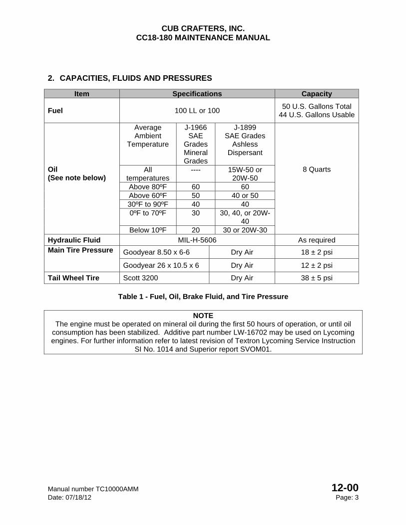
CUB CRAFTERS, INC. CC18-180 MAINTENANCE MANUAL
Manual number TC10000AMM 12-00 Date: 07/18/12 Page: 3
2. CAPACITIES, FLUIDS AND PRESSURES
Item Specifications Capacity
Fuel 100 LL or 100 50 U.S. Gallons Total
44 U.S. Gallons Usable
Oil (See note below)
Average Ambient
Temperature
J-1966 SAE
Grades Mineral Grades
J-1899 SAE Grades
Ashless Dispersant
8 Quarts All temperatures
---- 15W-50 or 20W-50
Above 80ºF 60 60 Above 60ºF 50 40 or 50 30ºF to 90ºF 40 40 0ºF to 70ºF 30 30, 40, or 20W-
40 Below 10ºF 20 30 or 20W-30
Hydraulic Fluid MIL-H-5606 As required Main Tire Pressure Goodyear 8.50 x 6-6 Dry Air 18 ± 2 psi
Goodyear 26 x 10.5 x 6 Dry Air 12 ± 2 psi
Tail Wheel Tire Scott 3200 Dry Air 38 ± 5 psi
Table 1 - Fuel, Oil, Brake Fluid, and Tire Pressure
NOTE
The engine must be operated on mineral oil during the first 50 hours of operation, or until oil consumption has been stabilized. Additive part number LW-16702 may be used on Lycoming engines. For further information refer to latest revision of Textron Lycoming Service Instruction
SI No. 1014 and Superior report SVOM01.

CUB CRAFTERS, INC. CC18-180 MAINTENANCE MANUAL
12-00 Manual number TC10000AMM Page: 4 Date: 07/18/12
INTENTIONALLY LEFT BLANK
CUB CRAFTERS, INC. CC18-180 MAINTENANCE MANUAL
Manual number TC10000AMM 12-20 Date: 05/20/08 Page: 1
12-20 SCHEDULED SERVICING
TABLE OF CONTENTS
1. GENERAL ............................................................................................................................. 2
2. MAINTENANCE PRACTICES .............................................................................................. 2
A. FUEL SYSTEM ............................................................................................................. 2
(1) DRAINING FUEL ....................................................................................................... 2
B. OIL SYSTEM ................................................................................................................. 2
(1) CHANGING ENGINE OIL ......................................................................................... 2
C. TIRES AND WHEELS ................................................................................................... 3
D. BATTERY ...................................................................................................................... 3
E. LUBRICATION .................................................................................................................. 4
CUB CRAFTERS, INC. CC18-180 MAINTENANCE MANUAL
12-20 Manual number TC10000AMM Page: 2 Date: 05/20/08
1. GENERAL
In this section, you will find the information required to perform scheduled maintenance.
2. MAINTENANCE PRACTICES
A. FUEL SYSTEM
(1) DRAINING FUEL
The aircraft has three fuel drains, one under each wing and one on the gascolator, located on the engine firewall.
CAUTION
Observe all precautions related to fuelling and de-fueling the aircraft. In particular, the following are highlighted:
Connect grounding wire to one of the wing tie-downs and ground the aircraft to an earth ground.
Do not operate any electrical equipment during the de-fueling operation. Operation of any electrical switch during the fueling operation is prohibited. Do not allow smoking or open flames within 100 feet (of the aircraft or fuel
servicing vehicle are prohibited. Do not operate radios, electric system, or electronic equipment during the fueling
or de-fueling operations. Do not drain fuel tanks within 100 feet of any electrical equipment capable of
producing sparks. Have a suitable fire extinguisher available at all times.
(a) Open wing and gascolator drain valves and allow fuel to drain into container.
(b) If the fuel has been drained and then the aircraft has been re-fueled, the engine must be run on the ground for enough time to purge the system of air prior to flight.
B. OIL SYSTEM
(1) CHANGING ENGINE OIL
(a) Warm engine
(b) Remove the upper and lower engine cowlings. (Refer to 71-10)
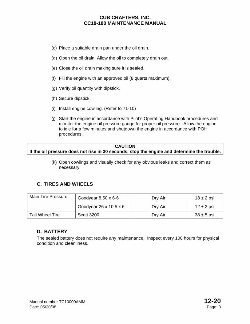
CUB CRAFTERS, INC. CC18-180 MAINTENANCE MANUAL
Manual number TC10000AMM 12-20 Date: 05/20/08 Page: 3
(c) Place a suitable drain pan under the oil drain.
(d) Open the oil drain. Allow the oil to completely drain out.
(e) Close the oil drain making sure it is sealed.
(f) Fill the engine with an approved oil (8 quarts maximum).
(g) Verify oil quantity with dipstick.
(h) Secure dipstick.
(i) Install engine cowling. (Refer to 71-10)
(j) Start the engine in accordance with Pilot’s Operating Handbook procedures and monitor the engine oil pressure gauge for proper oil pressure. Allow the engine to idle for a few minutes and shutdown the engine in accordance with POH procedures.
CAUTION
If the oil pressure does not rise in 30 seconds, stop the engine and determine the trouble.
(k) Open cowlings and visually check for any obvious leaks and correct them as necessary.
C. TIRES AND WHEELS Main Tire Pressure Goodyear 8.50 x 6-6 Dry Air 18 ± 2 psi
Goodyear 26 x 10.5 x 6 Dry Air 12 ± 2 psi
Tail Wheel Tire Scott 3200 Dry Air 38 ± 5 psi
D. BATTERY The sealed battery does not require any maintenance. Inspect every 100 hours for physical condition and cleanliness.
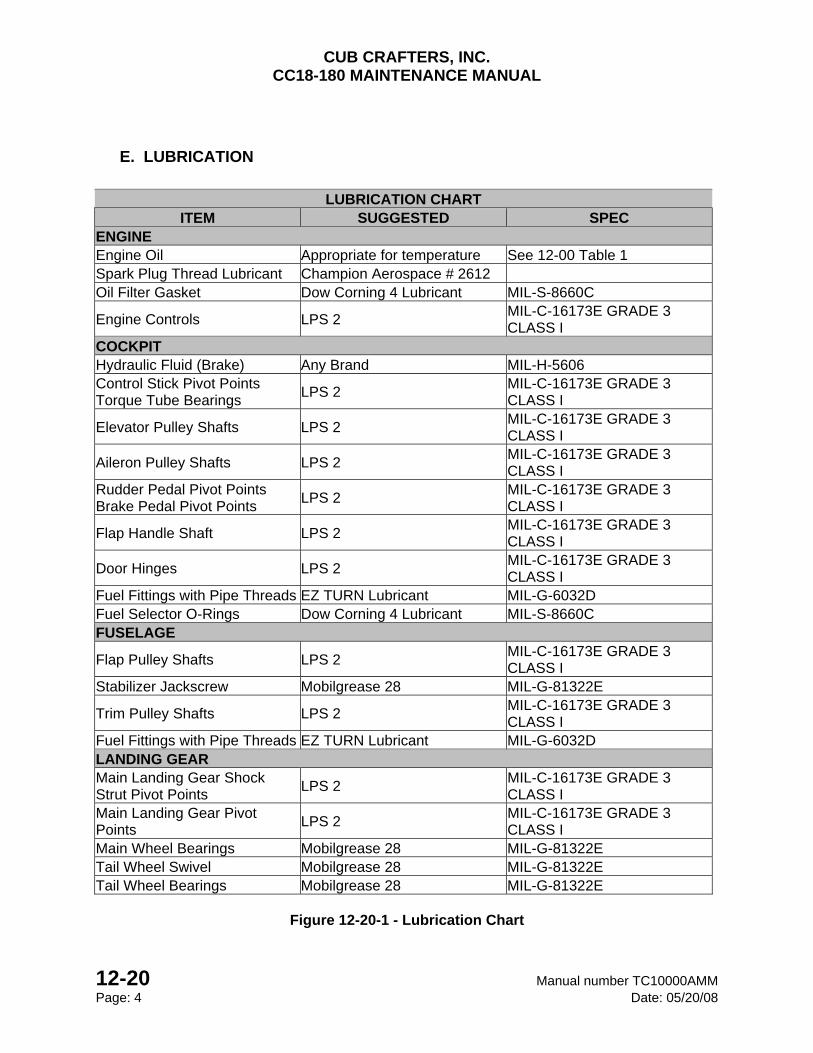
CUB CRAFTERS, INC. CC18-180 MAINTENANCE MANUAL
12-20 Manual number TC10000AMM Page: 4 Date: 05/20/08
E. LUBRICATION
LUBRICATION CHART
ITEM SUGGESTED SPEC ENGINE Engine Oil Appropriate for temperature See 12-00 Table 1 Spark Plug Thread Lubricant Champion Aerospace # 2612 Oil Filter Gasket Dow Corning 4 Lubricant MIL-S-8660C
Engine Controls LPS 2 MIL-C-16173E GRADE 3 CLASS I
COCKPIT Hydraulic Fluid (Brake) Any Brand MIL-H-5606 Control Stick Pivot Points Torque Tube Bearings
LPS 2 MIL-C-16173E GRADE 3 CLASS I
Elevator Pulley Shafts LPS 2 MIL-C-16173E GRADE 3 CLASS I
Aileron Pulley Shafts LPS 2 MIL-C-16173E GRADE 3 CLASS I
Rudder Pedal Pivot Points Brake Pedal Pivot Points
LPS 2 MIL-C-16173E GRADE 3 CLASS I
Flap Handle Shaft LPS 2 MIL-C-16173E GRADE 3 CLASS I
Door Hinges LPS 2 MIL-C-16173E GRADE 3 CLASS I
Fuel Fittings with Pipe Threads EZ TURN Lubricant MIL-G-6032D Fuel Selector O-Rings Dow Corning 4 Lubricant MIL-S-8660C FUSELAGE
Flap Pulley Shafts LPS 2 MIL-C-16173E GRADE 3 CLASS I
Stabilizer Jackscrew Mobilgrease 28 MIL-G-81322E
Trim Pulley Shafts LPS 2 MIL-C-16173E GRADE 3 CLASS I
Fuel Fittings with Pipe Threads EZ TURN Lubricant MIL-G-6032D LANDING GEAR Main Landing Gear Shock Strut Pivot Points
LPS 2 MIL-C-16173E GRADE 3 CLASS I
Main Landing Gear Pivot Points
LPS 2 MIL-C-16173E GRADE 3 CLASS I
Main Wheel Bearings Mobilgrease 28 MIL-G-81322E Tail Wheel Swivel Mobilgrease 28 MIL-G-81322E Tail Wheel Bearings Mobilgrease 28 MIL-G-81322E
Figure 12-20-1 - Lubrication Chart
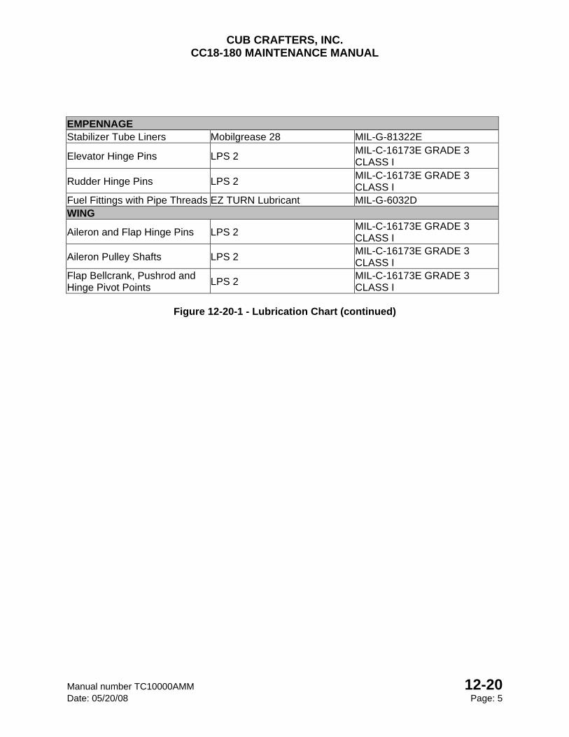
CUB CRAFTERS, INC. CC18-180 MAINTENANCE MANUAL
Manual number TC10000AMM 12-20 Date: 05/20/08 Page: 5
EMPENNAGE Stabilizer Tube Liners Mobilgrease 28 MIL-G-81322E
Elevator Hinge Pins LPS 2 MIL-C-16173E GRADE 3 CLASS I
Rudder Hinge Pins LPS 2 MIL-C-16173E GRADE 3 CLASS I
Fuel Fittings with Pipe Threads EZ TURN Lubricant MIL-G-6032D WING
Aileron and Flap Hinge Pins LPS 2 MIL-C-16173E GRADE 3 CLASS I
Aileron Pulley Shafts LPS 2 MIL-C-16173E GRADE 3 CLASS I
Flap Bellcrank, Pushrod and Hinge Pivot Points
LPS 2 MIL-C-16173E GRADE 3 CLASS I
Figure 12-20-1 - Lubrication Chart (continued)
CUB CRAFTERS, INC. CC18-180 MAINTENANCE MANUAL
12-20 Manual number TC10000AMM Page: 6 Date: 05/20/08
INTENTIONALLY LEFT BLANK

CHAPTER
20-00
STANDARD PRACTICES

CUB CRAFTERS, INC. CC18-180 MAINTENANCE MANUAL
Manual number TC10000AMM 20-00 Date: 05/20/08 Page: 1
20-00 STANDARD PRACTICES
TABLE OF CONTENTS
1. GENERAL-TORQUE VALUES ............................................................................................. 2
2. DEFINITIONS ....................................................................................................................... 2
3. TORQUING REQUIREMENTS ............................................................................................. 2
4. USE OF TORQUE WRENCHES AND ADAPTORS ............................................................. 3
5. TORQUING PATTERNS ....................................................................................................... 5
6. SPECIFIC TORQUE REQUIREMENTS ............................................................................... 6
7. GENERAL TORQUE VALUES ............................................................................................. 7
CUB CRAFTERS, INC. CC18-180 MAINTENANCE MANUAL
20-00 Manual number TC10000AMM Page: 2 Date: 05/20/08
1. GENERAL-TORQUE VALUES
This chapter gives the requirements for torquing the fasteners on the CC18-180. No lubricating or anti-seize compounds are to be applied to threaded fasteners except when specified. At the time of installation, the threads must be clean and free of corrosion, paint or any products other than those applied by the fastener’s manufacturer.
2. DEFINITIONS
Running torque: The average torque developed after the fastener is at least one full thread through the nut, but prior to the tightening of the joint (also called self-locking torque, locking torque, friction drag torque). Assembly torque: The torque required by Design Engineering in order to create the desired axial load on the bolt/nut assembly (also called tightening torque, installation torque).
3. TORQUING REQUIREMENTS
Whenever possible, the nut shall be turned during torquing. Where it is necessary to tighten the fastener assembly from the head, the installation torque shall be the maximum torque indicated in Chapter 20-00-7 + 10 percent. (Note: This is only applicable for fasteners greater than 3/16” in diameter). When nuts are to be secured to fasteners by means of cotter pins or lock wire, the low side of the specified torque range shall be approached for tightening. If necessary, tightening shall be continued until the next slot aligns with the hole. Nuts shall not be loosened to obtain the required alignment. The maximum torque shall not be exceeded. Threaded fasteners which have been torqued above the maximum value specified shall not be backed off and retorqued but shall be removed, rejected and rendered unserviceable. If there is doubt that a fastener has been under-torqued, the nut shall be backed off one complete rotation (360°) maximum and retightened to the specified value; the bolt, screw or stud must not be allowed to rotate.
CUB CRAFTERS, INC. CC18-180 MAINTENANCE MANUAL
Manual number TC10000AMM 20-00 Date: 05/20/08 Page: 3
4. USE OF TORQUE WRENCHES AND ADAPTORS
All final torquing shall be carried out with certified torque wrenches or torque screwdrivers. When adaptors or extensions are used on manually operated torque wrenches, they shall be aligned as shown in Figure 20-00-1 and the dial reading required shall be calculated from the following formula: Dial Reading = Specified Torque X L L+L1 Dimensions must be measured in the same units (i.e. both in inches, both in feet etc.) for each calculation. Different units must not be mixed.
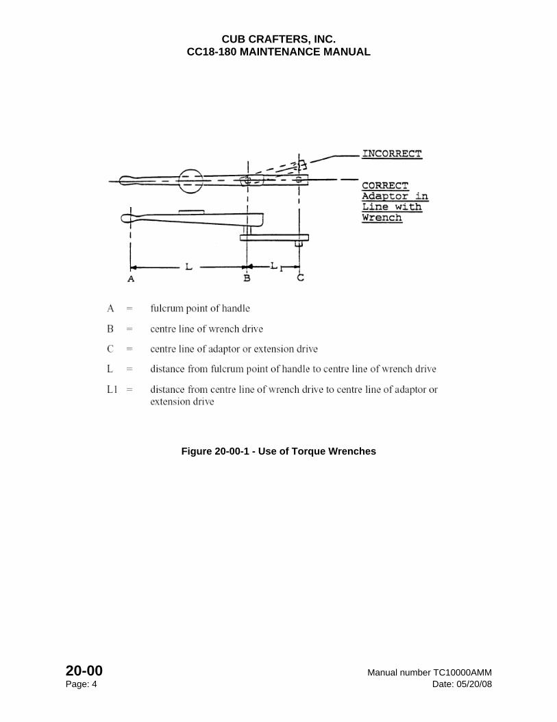
CUB CRAFTERS, INC. CC18-180 MAINTENANCE MANUAL
20-00 Manual number TC10000AMM Page: 4 Date: 05/20/08
Figure 20-00-1 - Use of Torque Wrenches
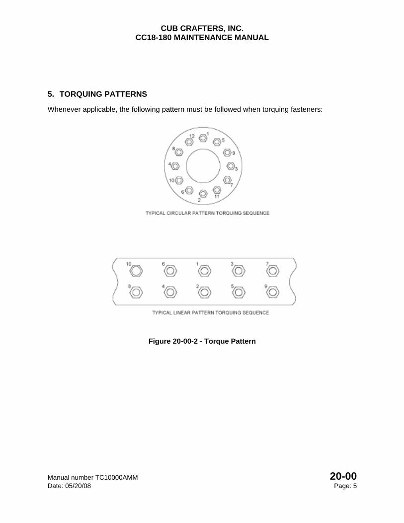
CUB CRAFTERS, INC. CC18-180 MAINTENANCE MANUAL
Manual number TC10000AMM 20-00 Date: 05/20/08 Page: 5
5. TORQUING PATTERNS
Whenever applicable, the following pattern must be followed when torquing fasteners:
Figure 20-00-2 - Torque Pattern
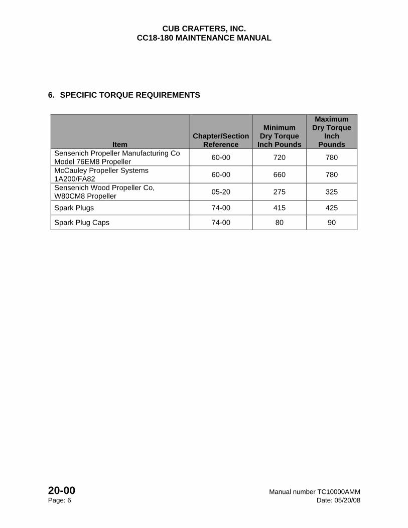
CUB CRAFTERS, INC. CC18-180 MAINTENANCE MANUAL
20-00 Manual number TC10000AMM Page: 6 Date: 05/20/08
6. SPECIFIC TORQUE REQUIREMENTS
Item Chapter/Section
Reference
Minimum Dry Torque
Inch Pounds
Maximum Dry Torque
Inch Pounds
Sensenich Propeller Manufacturing Co Model 76EM8 Propeller
60-00 720 780
McCauley Propeller Systems 1A200/FA82
60-00 660 780
Sensenich Wood Propeller Co, W80CM8 Propeller
05-20 275 325
Spark Plugs 74-00 415 425
Spark Plug Caps 74-00 80 90
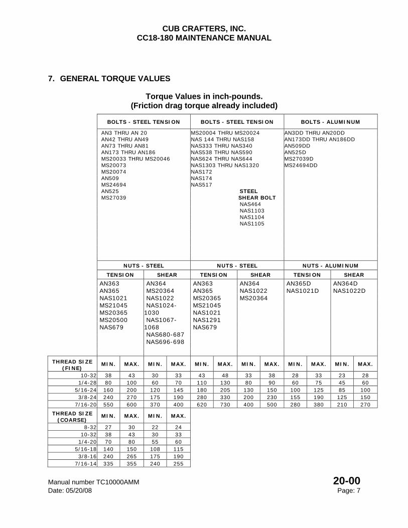
CUB CRAFTERS, INC. CC18-180 MAINTENANCE MANUAL
Manual number TC10000AMM 20-00 Date: 05/20/08 Page: 7
7. GENERAL TORQUE VALUES
Torque Values in inch-pounds. (Friction drag torque already included)
BOLTS - STEEL TENSION BOLTS - STEEL TENSION BOLTS - ALUMINUM
AN3 THRU AN 20 AN42 THRU AN49 AN73 THRU AN81 AN173 THRU AN186 MS20033 THRU MS20046 MS20073 MS20074 AN509 MS24694 AN525 MS27039
MS20004 THRU MS20024 NAS 144 THRU NAS158 NAS333 THRU NAS340 NAS538 THRU NAS590 NAS624 THRU NAS644 NAS1303 THRU NAS1320 NAS172 NAS174 NAS517 STEEL SHEAR BOLT NAS464 NAS1103 NAS1104 NAS1105
AN3DD THRU AN20DD AN173DD THRU AN186DD AN509DD AN525D MS27039D MS24694DD
NUTS - STEEL NUTS - STEEL NUTS - ALUMINUM
TENSION SHEAR TENSION SHEAR TENSION SHEAR AN363
AN365 NAS1021 MS21045 MS20365 MS20500 NAS679
AN364 MS20364 NAS1022 NAS1024-1030 NAS1067-1068 NAS680-687 NAS696-698
AN363 AN365 MS20365 MS21045 NAS1021 NAS1291 NAS679
AN364 NAS1022 MS20364
AN365D NAS1021D
AN364D NAS1022D
THREAD SIZE (FINE)
MIN. MAX. MIN. MAX. MIN. MAX. MIN. MAX. MIN. MAX. MIN. MAX.
10-32 38 43 30 33 43 48 33 38 28 33 23 28 1/4-28 80 100 60 70 110 130 80 90 60 75 45 60
5/16-24 160 200 120 145 180 205 130 150 100 125 85 100 3/8-24 240 270 175 190 280 330 200 230 155 190 125 150
7/16-20 550 600 370 400 620 730 400 500 280 380 210 270 THREAD SIZE
(COARSE) MIN. MAX. MIN. MAX.
8-32 27 30 22 24
10-32 38 43 30 33 1/4-20 70 80 55 60
5/16-18 140 150 108 115 3/8-16 240 265 175 190
7/16-14 335 355 240 255
CUB CRAFTERS, INC. CC18-180 MAINTENANCE MANUAL
20-00 Manual number TC10000AMM Page: 8 Date: 05/20/08
INTENTIONALLY LEFT BLANK
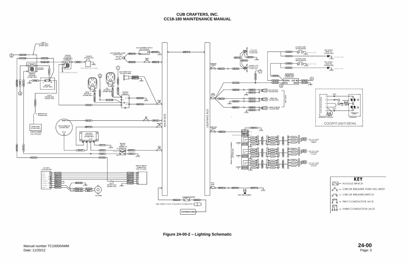
CUB CRAFTERS, INC. CC18-180 MAINTENANCE MANUAL
Manual number TC10000AMM 24-00 Date: 11/20/12 Page: 3
Figure 24-00-2 – Lighting Schematic
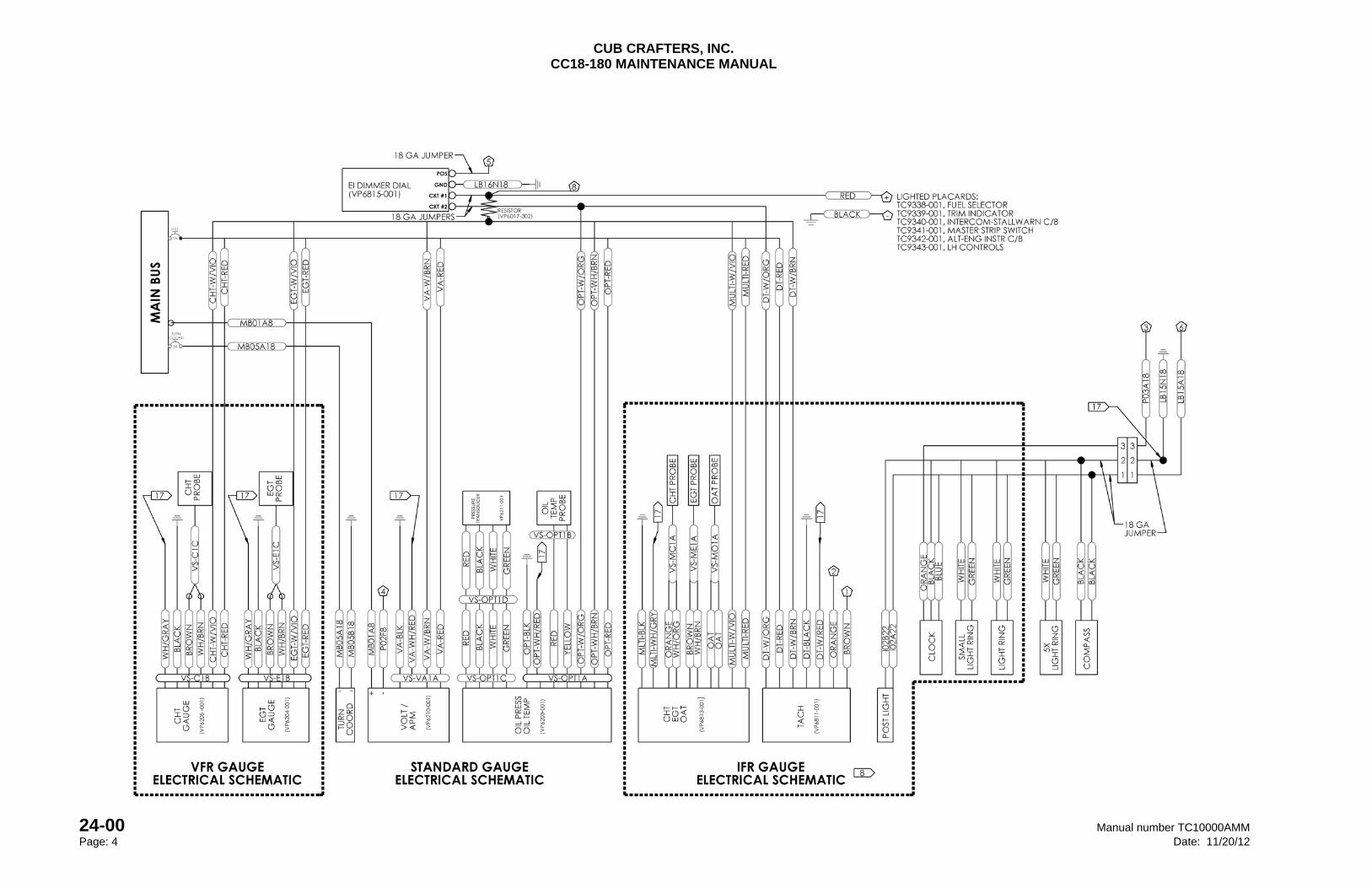
CUB CRAFTERS, INC. CC18-180 MAINTENANCE MANUAL
24-00 Manual number TC10000AMM Page: 4 Date: 11/20/12
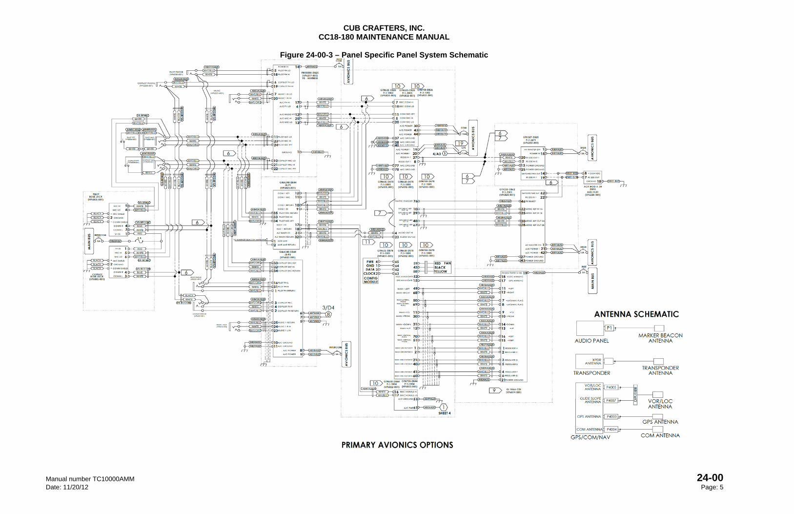
CUB CRAFTERS, INC. CC18-180 MAINTENANCE MANUAL
Manual number TC10000AMM 24-00 Date: 11/20/12 Page: 5
Figure 24-00-3 – Panel Specific Panel System Schematic
CUB CRAFTERS, INC. CC18-180 MAINTENANCE MANUAL
24-00 Manual number TC10000AMM Page: 6 Date: 11/20/12
Figure 24-00-4 – Primary Avionics System Schematic
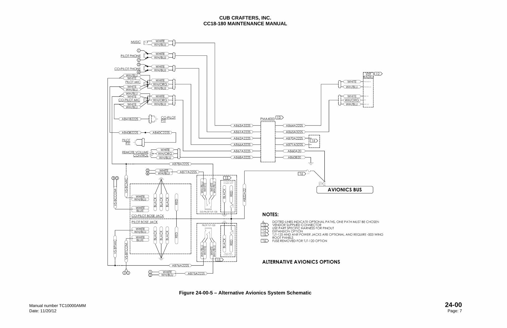
CUB CRAFTERS, INC. CC18-180 MAINTENANCE MANUAL
Manual number TC10000AMM 24-00 Date: 11/20/12 Page: 7
Figure 24-00-5 – Alternative Avionics System Schematic
CHAPTER
25-00
EQUIPMENT AND FURNISHINGS

CUB CRAFTERS, INC. CC18-180 MAINTENANCE MANUAL
Manual number TC10000AMM 25-00 Date: 4/15/05 Page: 1
25-00 EQUIPMENT AND FURNISHINGS
TABLE OF CONTENTS 1. GENERAL ............................................................................................................................. 2
2. TROUBLESHOOTING .......................................................................................................... 2
3. MAINTENANCE PRACTICES .............................................................................................. 3
A. FRONT SEAT ................................................................................................................... 3
(1) INSPECTION .............................................................................................................. 3
B. AFT SEAT ......................................................................................................................... 3
(1) INSPECTION .............................................................................................................. 3
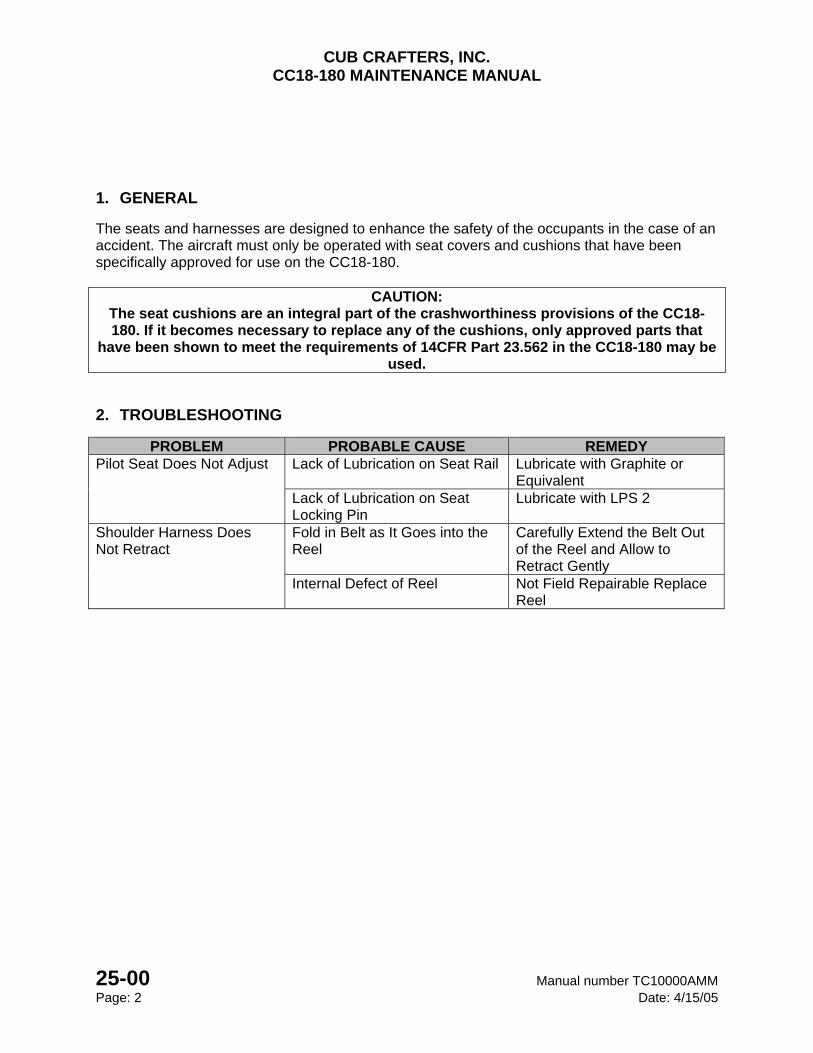
CUB CRAFTERS, INC. CC18-180 MAINTENANCE MANUAL
25-00 Manual number TC10000AMM Page: 2 Date: 4/15/05
1. GENERAL
The seats and harnesses are designed to enhance the safety of the occupants in the case of an accident. The aircraft must only be operated with seat covers and cushions that have been specifically approved for use on the CC18-180.
CAUTION: The seat cushions are an integral part of the crashworthiness provisions of the CC18-180. If it becomes necessary to replace any of the cushions, only approved parts that
have been shown to meet the requirements of 14CFR Part 23.562 in the CC18-180 may be used.
2. TROUBLESHOOTING
PROBLEM PROBABLE CAUSE REMEDY Pilot Seat Does Not Adjust Lack of Lubrication on Seat Rail Lubricate with Graphite or
Equivalent Lack of Lubrication on Seat Locking Pin
Lubricate with LPS 2
Shoulder Harness Does Not Retract
Fold in Belt as It Goes into the Reel
Carefully Extend the Belt Out of the Reel and Allow to Retract Gently
Internal Defect of Reel Not Field Repairable Replace Reel
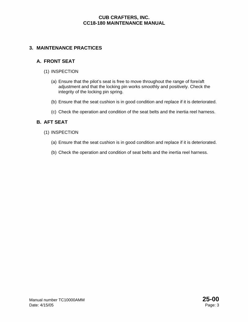
CUB CRAFTERS, INC. CC18-180 MAINTENANCE MANUAL
Manual number TC10000AMM 25-00 Date: 4/15/05 Page: 3
3. MAINTENANCE PRACTICES
A. FRONT SEAT
(1) INSPECTION
(a) Ensure that the pilot’s seat is free to move throughout the range of fore/aft adjustment and that the locking pin works smoothly and positively. Check the integrity of the locking pin spring.
(b) Ensure that the seat cushion is in good condition and replace if it is deteriorated.
(c) Check the operation and condition of the seat belts and the inertia reel harness.
B. AFT SEAT
(1) INSPECTION
(a) Ensure that the seat cushion is in good condition and replace if it is deteriorated.
(b) Check the operation and condition of seat belts and the inertia reel harness.

CUB CRAFTERS, INC. CC18-180 MAINTENANCE MANUAL
25-00 Manual number TC10000AMM Page: 4 Date: 4/15/05
INTENTIONALLY LEFT BLANK
CHAPTER
27
FLIGHT CONTROLS

CUB CRAFTERS, INC. CC18-180 MAINTENANCE MANUAL
Manual number TC10000AMM 27 Date: 05/20/08 Page: i
27 FLIGHT CONTROLS
27-00 ............................................................................................................. FLIGHT CONTROLS
27-10 ............................................................................................................................. AILERONS
27-20 ............................................................................................................................... RUDDER
27-30 ............................................................................................................................ ELEVATOR
27-31 .................................................................................................. STALL WARNING SYSTEM
27-40 .................................................................................................. HORIZONTAL STABILIZER
27-50 ................................................................................................................................... FLAPS
CUB CRAFTERS, INC. CC18-180 MAINTENANCE MANUAL
27 Manual number TC10000AMM Page: ii Date: 05/20/08
INTENTIONALLY LEFT BLANK
CUB CRAFTERS, INC. CC18-180 MAINTENANCE MANUAL
Manual number TC10000AMM 27-00 Date: 05/20/08 Page: 1
27-00 FLIGHT CONTROLS
TABLE OF CONTENTS
1. GENERAL .............................................................................................................................. 2
2. MAINTENANCE PRACTICES ............................................................................................... 2
A. INSPECTION .................................................................................................................... 2
(1) FUSELAGE ................................................................................................................... 2
(2) TAIL SURFACES .......................................................................................................... 2
3. TROUBLESHOOTING ........................................................................................................... 3
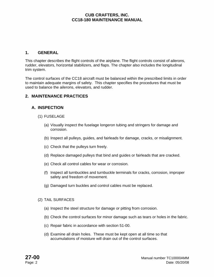
CUB CRAFTERS, INC. CC18-180 MAINTENANCE MANUAL
27-00 Manual number TC10000AMM Page: 2 Date: 05/20/08
1. GENERAL
This chapter describes the flight controls of the airplane. The flight controls consist of ailerons, rudder, elevators, horizontal stabilizers, and flaps. The chapter also includes the longitudinal trim system. The control surfaces of the CC18 aircraft must be balanced within the prescribed limits in order to maintain adequate margins of safety. This chapter specifies the procedures that must be used to balance the ailerons, elevators, and rudder.
2. MAINTENANCE PRACTICES
A. INSPECTION
(1) FUSELAGE
(a) Visually inspect the fuselage longeron tubing and stringers for damage and corrosion.
(b) Inspect all pulleys, guides, and fairleads for damage, cracks, or misalignment.
(c) Check that the pulleys turn freely.
(d) Replace damaged pulleys that bind and guides or fairleads that are cracked.
(e) Check all control cables for wear or corrosion.
(f) Inspect all turnbuckles and turnbuckle terminals for cracks, corrosion, improper safety and freedom of movement.
(g) Damaged turn buckles and control cables must be replaced.
(2) TAIL SURFACES
(a) Inspect the steel structure for damage or pitting from corrosion.
(b) Check the control surfaces for minor damage such as tears or holes in the fabric.
(c) Repair fabric in accordance with section 51-00.
(d) Examine all drain holes. These must be kept open at all time so that accumulations of moisture will drain out of the control surfaces.
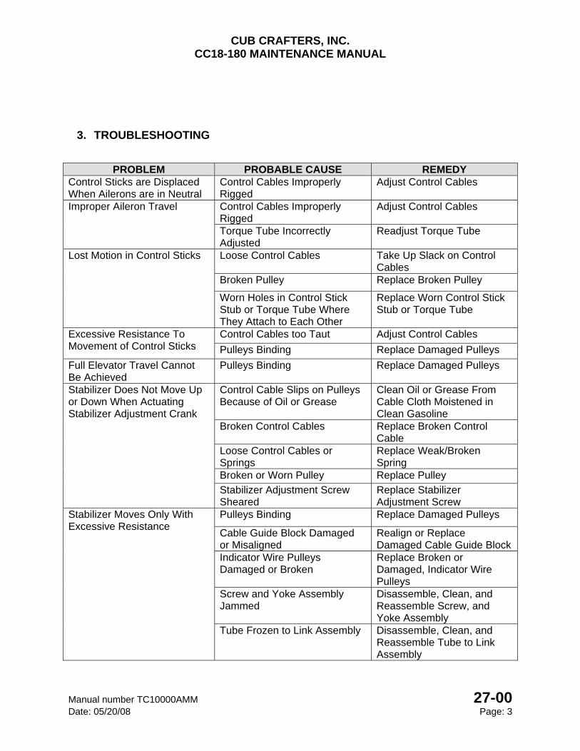
CUB CRAFTERS, INC. CC18-180 MAINTENANCE MANUAL
Manual number TC10000AMM 27-00 Date: 05/20/08 Page: 3
3. TROUBLESHOOTING
PROBLEM PROBABLE CAUSE REMEDY
Control Sticks are Displaced When Ailerons are in Neutral
Control Cables Improperly Rigged
Adjust Control Cables
Improper Aileron Travel Control Cables Improperly Rigged
Adjust Control Cables
Torque Tube Incorrectly Adjusted
Readjust Torque Tube
Lost Motion in Control Sticks Loose Control Cables Take Up Slack on Control Cables
Broken Pulley Replace Broken Pulley
Worn Holes in Control Stick Stub or Torque Tube Where They Attach to Each Other
Replace Worn Control Stick Stub or Torque Tube
Excessive Resistance To Movement of Control Sticks
Control Cables too Taut Adjust Control Cables
Pulleys Binding Replace Damaged Pulleys
Full Elevator Travel Cannot Be Achieved
Pulleys Binding Replace Damaged Pulleys
Stabilizer Does Not Move Up or Down When Actuating Stabilizer Adjustment Crank
Control Cable Slips on Pulleys Because of Oil or Grease
Clean Oil or Grease From Cable Cloth Moistened in Clean Gasoline
Broken Control Cables Replace Broken Control Cable
Loose Control Cables or Springs
Replace Weak/Broken Spring
Broken or Worn Pulley Replace Pulley
Stabilizer Adjustment Screw Sheared
Replace Stabilizer Adjustment Screw
Stabilizer Moves Only With Excessive Resistance
Pulleys Binding Replace Damaged Pulleys
Cable Guide Block Damaged or Misaligned
Realign or Replace Damaged Cable Guide Block
Indicator Wire Pulleys Damaged or Broken
Replace Broken or Damaged, Indicator Wire Pulleys
Screw and Yoke Assembly Jammed
Disassemble, Clean, and Reassemble Screw, and Yoke Assembly
Tube Frozen to Link Assembly Disassemble, Clean, and Reassemble Tube to Link Assembly
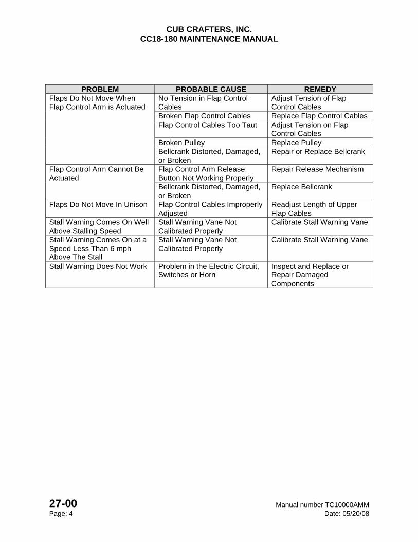
CUB CRAFTERS, INC. CC18-180 MAINTENANCE MANUAL
27-00 Manual number TC10000AMM Page: 4 Date: 05/20/08
PROBLEM PROBABLE CAUSE REMEDY
Flaps Do Not Move When Flap Control Arm is Actuated
No Tension in Flap Control Cables
Adjust Tension of Flap Control Cables
Broken Flap Control Cables Replace Flap Control Cables Flap Control Cables Too Taut Adjust Tension on Flap
Control Cables Broken Pulley Replace Pulley Bellcrank Distorted, Damaged, or Broken
Repair or Replace Bellcrank
Flap Control Arm Cannot Be Actuated
Flap Control Arm Release Button Not Working Properly
Repair Release Mechanism
Bellcrank Distorted, Damaged, or Broken
Replace Bellcrank
Flaps Do Not Move In Unison Flap Control Cables Improperly Adjusted
Readjust Length of Upper Flap Cables
Stall Warning Comes On Well Above Stalling Speed
Stall Warning Vane Not Calibrated Properly
Calibrate Stall Warning Vane
Stall Warning Comes On at a Speed Less Than 6 mph Above The Stall
Stall Warning Vane Not Calibrated Properly
Calibrate Stall Warning Vane
Stall Warning Does Not Work Problem in the Electric Circuit, Switches or Horn
Inspect and Replace or Repair Damaged Components
CUB CRAFTERS, INC. CC18-180 MAINTENANCE MANUAL
Manual number TC10000AMM 27-10 Date: 05/20/08 Page: 1
27-10 AILERONS
TABLE OF CONTENTS
1. GENERAL .......................................................................................................................... 2
2. MAINTANENCE PRACTICES ........................................................................................... 2
A. REMOVAL ...................................................................................................................... 2
B. INSTALLATION .............................................................................................................. 3
C. RIGGING ........................................................................................................................ 5
3. BALANCING ...................................................................................................................... 8
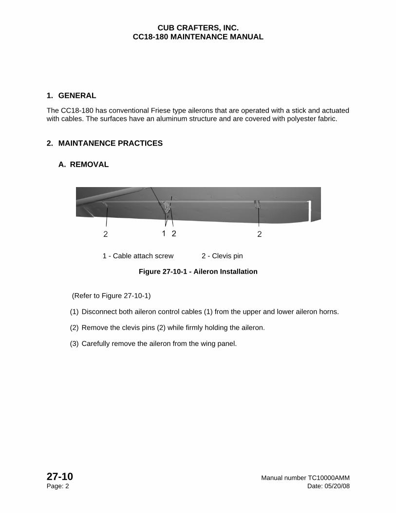
CUB CRAFTERS, INC. CC18-180 MAINTENANCE MANUAL
27-10 Manual number TC10000AMM Page: 2 Date: 05/20/08
1. GENERAL
The CC18-180 has conventional Friese type ailerons that are operated with a stick and actuated with cables. The surfaces have an aluminum structure and are covered with polyester fabric.
2. MAINTANENCE PRACTICES
A. REMOVAL
1 - Cable attach screw 2 - Clevis pin
Figure 27-10-1 - Aileron Installation
(Refer to Figure 27-10-1)
(1) Disconnect both aileron control cables (1) from the upper and lower aileron horns.
(2) Remove the clevis pins (2) while firmly holding the aileron.
(3) Carefully remove the aileron from the wing panel.
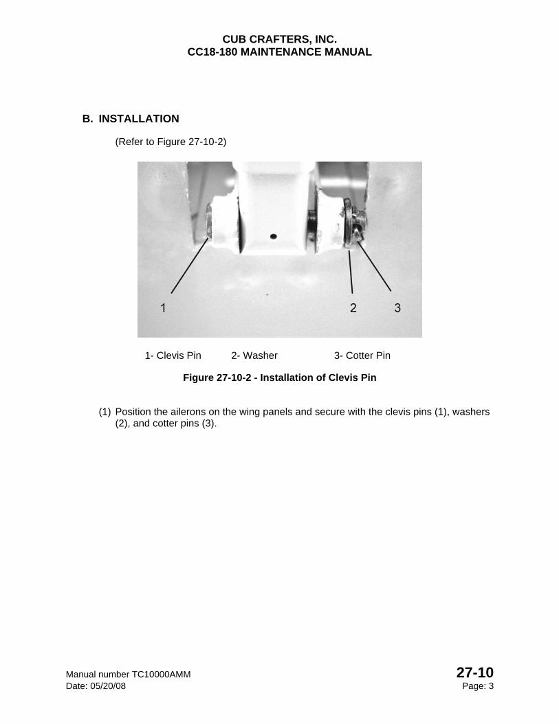
CUB CRAFTERS, INC. CC18-180 MAINTENANCE MANUAL
Manual number TC10000AMM 27-10 Date: 05/20/08 Page: 3
B. INSTALLATION
(Refer to Figure 27-10-2)
1- Clevis Pin 2- Washer 3- Cotter Pin
Figure 27-10-2 - Installation of Clevis Pin
(1) Position the ailerons on the wing panels and secure with the clevis pins (1), washers (2), and cotter pins (3).
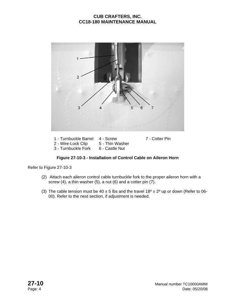
CUB CRAFTERS, INC. CC18-180 MAINTENANCE MANUAL
27-10 Manual number TC10000AMM Page: 4 Date: 05/20/08
1 - Turnbuckle Barrel 4 - Screw 7 - Cotter Pin 2 - Wire-Lock Clip 5 - Thin Washer 3 - Turnbuckle Fork 6 - Castle Nut
Figure 27-10-3 - Installation of Control Cable on Aileron Horn
Refer to Figure 27-10-3
(2) Attach each aileron control cable turnbuckle fork to the proper aileron horn with a screw (4), a thin washer (5), a nut (6) and a cotter pin (7).
(3) The cable tension must be 40 ± 5 lbs and the travel 18º ± 2º up or down (Refer to 06-00). Refer to the next section, if adjustment is needed.
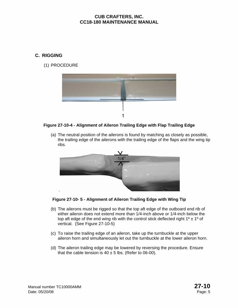
CUB CRAFTERS, INC. CC18-180 MAINTENANCE MANUAL
Manual number TC10000AMM 27-10 Date: 05/20/08 Page: 5
C. RIGGING
(1) PROCEDURE
Figure 27-10-4 - Alignment of Aileron Trailing Edge with Flap Trailing Edge
(a) The neutral position of the ailerons is found by matching as closely as possible, the trailing edge of the ailerons with the trailing edge of the flaps and the wing tip ribs.
.
Figure 27-10- 5 - Alignment of Aileron Trailing Edge with Wing Tip
(b) The ailerons must be rigged so that the top aft edge of the outboard end rib of either aileron does not extend more than 1/4-inch above or 1/4-inch below the top aft edge of the end wing rib with the control stick deflected right 1º ± 1º of vertical. (See Figure 27-10-5)
(c) To raise the trailing edge of an aileron, take up the turnbuckle at the upper aileron horn and simultaneously let out the turnbuckle at the lower aileron horn.
(d) The aileron trailing edge may be lowered by reversing the procedure. Ensure that the cable tension is 40 ± 5 lbs. (Refer to 06-00).
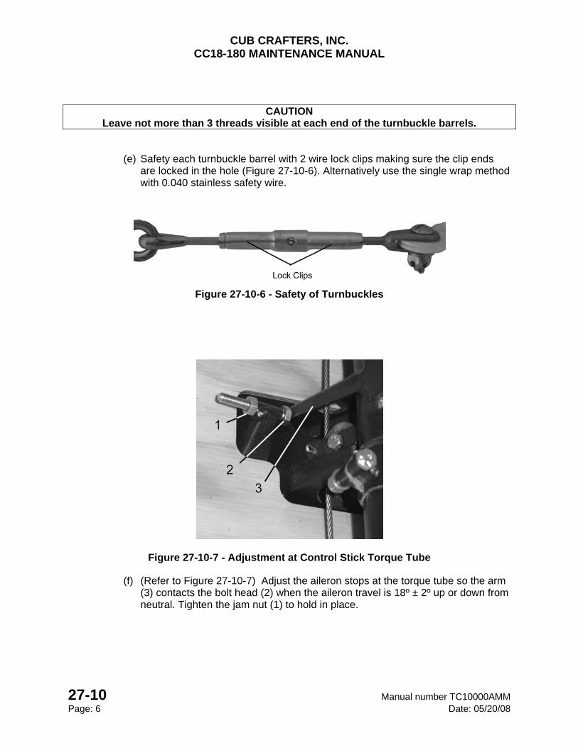
CUB CRAFTERS, INC. CC18-180 MAINTENANCE MANUAL
27-10 Manual number TC10000AMM Page: 6 Date: 05/20/08
CAUTION Leave not more than 3 threads visible at each end of the turnbuckle barrels.
(e) Safety each turnbuckle barrel with 2 wire lock clips making sure the clip ends are locked in the hole (Figure 27-10-6). Alternatively use the single wrap method with 0.040 stainless safety wire.
Figure 27-10-6 - Safety of Turnbuckles
Figure 27-10-7 - Adjustment at Control Stick Torque Tube
(f) (Refer to Figure 27-10-7) Adjust the aileron stops at the torque tube so the arm (3) contacts the bolt head (2) when the aileron travel is 18º ± 2º up or down from neutral. Tighten the jam nut (1) to hold in place.
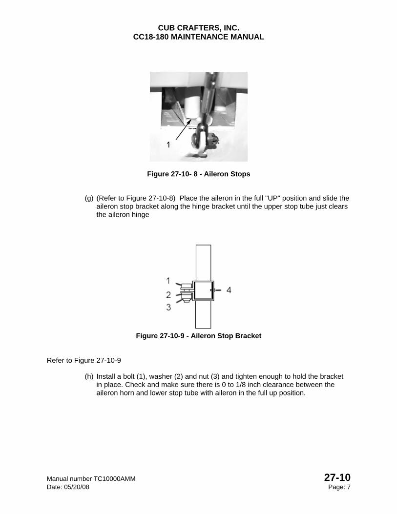
CUB CRAFTERS, INC. CC18-180 MAINTENANCE MANUAL
Manual number TC10000AMM 27-10 Date: 05/20/08 Page: 7
Figure 27-10- 8 - Aileron Stops
(g) (Refer to Figure 27-10-8) Place the aileron in the full "UP" position and slide the aileron stop bracket along the hinge bracket until the upper stop tube just clears the aileron hinge
Figure 27-10-9 - Aileron Stop Bracket
Refer to Figure 27-10-9
(h) Install a bolt (1), washer (2) and nut (3) and tighten enough to hold the bracket in place. Check and make sure there is 0 to 1/8 inch clearance between the aileron horn and lower stop tube with aileron in the full up position.
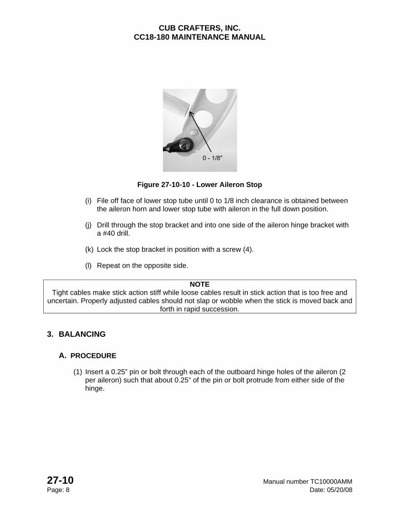
CUB CRAFTERS, INC. CC18-180 MAINTENANCE MANUAL
27-10 Manual number TC10000AMM Page: 8 Date: 05/20/08
Figure 27-10-10 - Lower Aileron Stop
(i) File off face of lower stop tube until 0 to 1/8 inch clearance is obtained between the aileron horn and lower stop tube with aileron in the full down position.
(j) Drill through the stop bracket and into one side of the aileron hinge bracket with a #40 drill.
(k) Lock the stop bracket in position with a screw (4).
(l) Repeat on the opposite side.
NOTE
Tight cables make stick action stiff while loose cables result in stick action that is too free and uncertain. Properly adjusted cables should not slap or wobble when the stick is moved back and
forth in rapid succession.
3. BALANCING
A. PROCEDURE
(1) Insert a 0.25” pin or bolt through each of the outboard hinge holes of the aileron (2 per aileron) such that about 0.25” of the pin or bolt protrude from either side of the hinge.
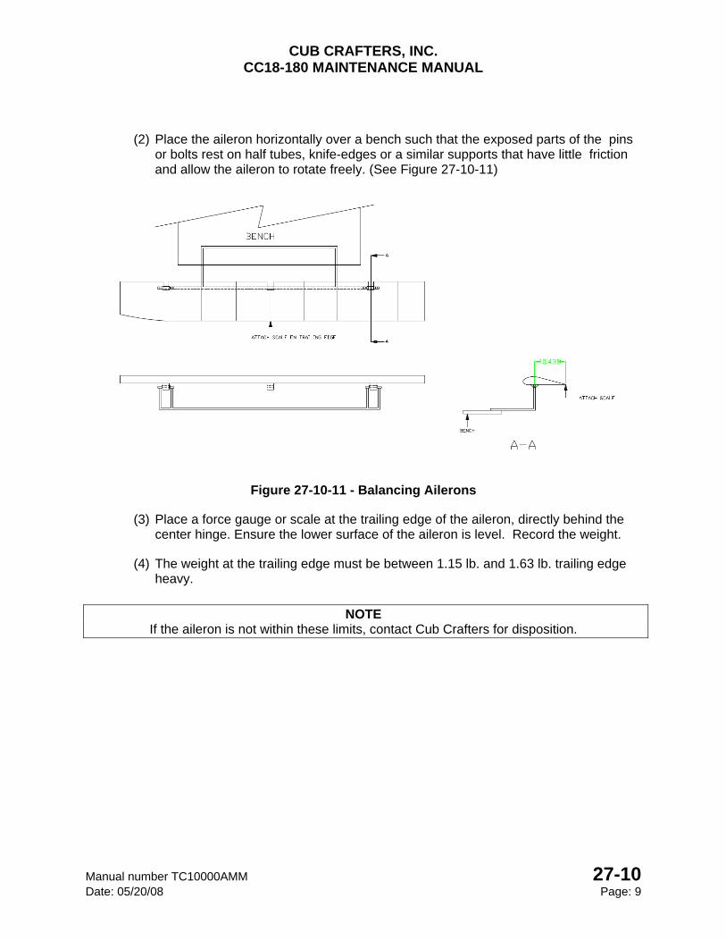
CUB CRAFTERS, INC. CC18-180 MAINTENANCE MANUAL
Manual number TC10000AMM 27-10 Date: 05/20/08 Page: 9
(2) Place the aileron horizontally over a bench such that the exposed parts of the pins or bolts rest on half tubes, knife-edges or a similar supports that have little friction and allow the aileron to rotate freely. (See Figure 27-10-11)
Figure 27-10-11 - Balancing Ailerons
(3) Place a force gauge or scale at the trailing edge of the aileron, directly behind the center hinge. Ensure the lower surface of the aileron is level. Record the weight.
(4) The weight at the trailing edge must be between 1.15 lb. and 1.63 lb. trailing edge heavy.
NOTE
If the aileron is not within these limits, contact Cub Crafters for disposition.

CUB CRAFTERS, INC. CC18-180 MAINTENANCE MANUAL
27-10 Manual number TC10000AMM Page: 10 Date: 05/20/08
INTENTIONALLY LEFT BLANK
CUB CRAFTERS, INC. CC18-180 MAINTENANCE MANUAL
Manual number TC10000AMM 27-20 Date: 05/20/2008 Page 1
27-20 RUDDER TABLE OF CONTENTS 1. GENERAL ......................................................................................................................... 2
2. MAINTANENCE PRACTICES .......................................................................................... 2
A. REMOVAL ......................................................................................................................... 2
B. INSTALLATION ................................................................................................................. 3
C. RIGGING ........................................................................................................................... 4
3. BALANCING ..................................................................................................................... 5
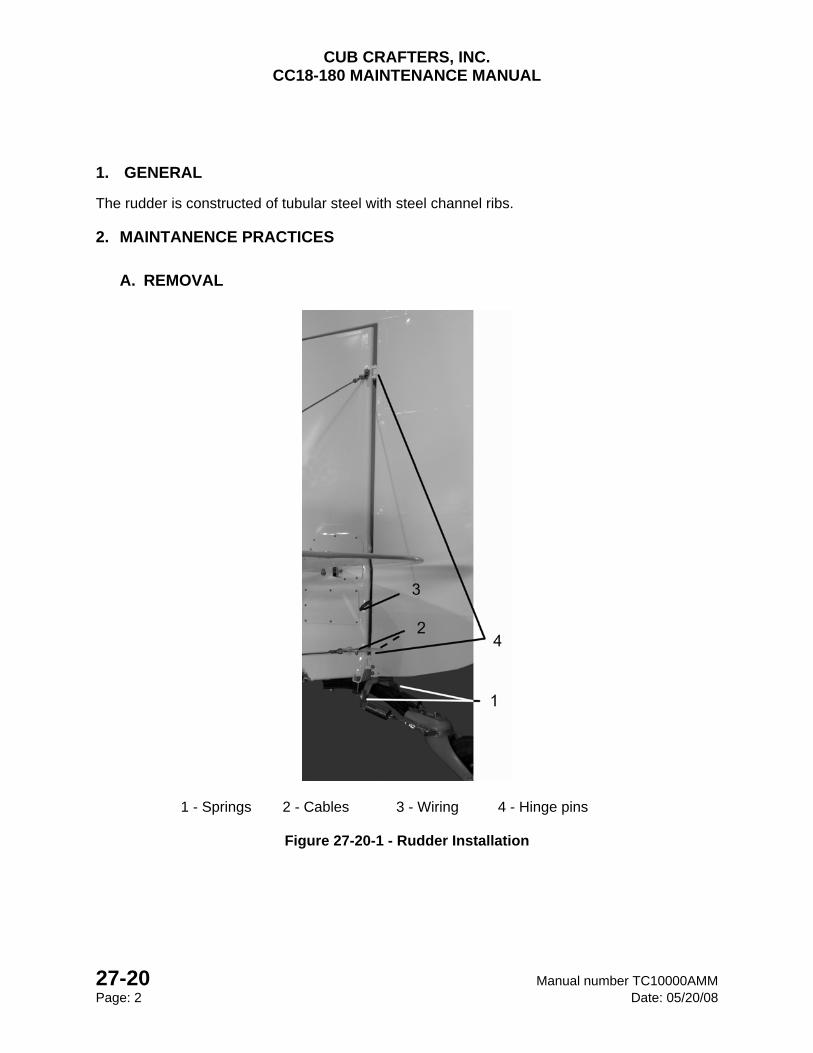
CUB CRAFTERS, INC. CC18-180 MAINTENANCE MANUAL
27-20 Manual number TC10000AMM Page: 2 Date: 05/20/08
1. GENERAL
The rudder is constructed of tubular steel with steel channel ribs.
2. MAINTANENCE PRACTICES
A. REMOVAL
1 - Springs 2 - Cables 3 - Wiring 4 - Hinge pins
Figure 27-20-1 - Rudder Installation
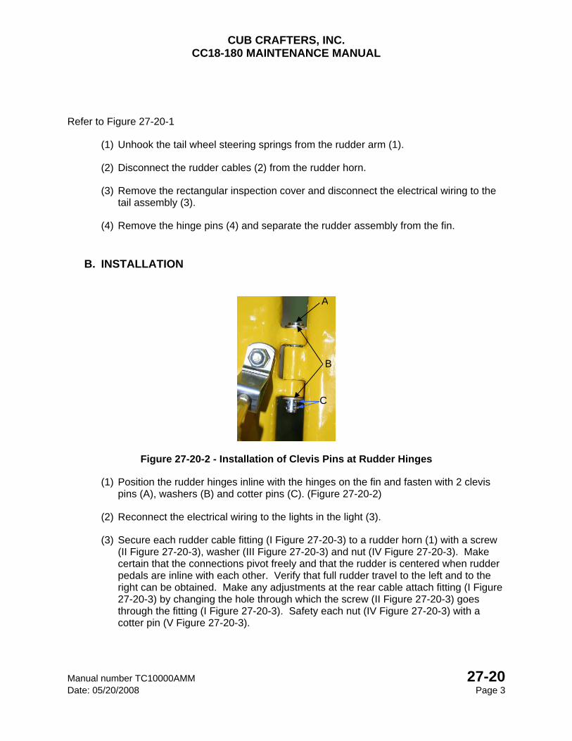
CUB CRAFTERS, INC. CC18-180 MAINTENANCE MANUAL
Manual number TC10000AMM 27-20 Date: 05/20/2008 Page 3
Refer to Figure 27-20-1
(1) Unhook the tail wheel steering springs from the rudder arm (1).
(2) Disconnect the rudder cables (2) from the rudder horn.
(3) Remove the rectangular inspection cover and disconnect the electrical wiring to the tail assembly (3).
(4) Remove the hinge pins (4) and separate the rudder assembly from the fin.
B. INSTALLATION
Figure 27-20-2 - Installation of Clevis Pins at Rudder Hinges
(1) Position the rudder hinges inline with the hinges on the fin and fasten with 2 clevis pins (A), washers (B) and cotter pins (C). (Figure 27-20-2)
(2) Reconnect the electrical wiring to the lights in the light (3).
(3) Secure each rudder cable fitting (I Figure 27-20-3) to a rudder horn (1) with a screw (II Figure 27-20-3), washer (III Figure 27-20-3) and nut (IV Figure 27-20-3). Make certain that the connections pivot freely and that the rudder is centered when rudder pedals are inline with each other. Verify that full rudder travel to the left and to the right can be obtained. Make any adjustments at the rear cable attach fitting (I Figure 27-20-3) by changing the hole through which the screw (II Figure 27-20-3) goes through the fitting (I Figure 27-20-3). Safety each nut (IV Figure 27-20-3) with a cotter pin (V Figure 27-20-3).
A
B
C
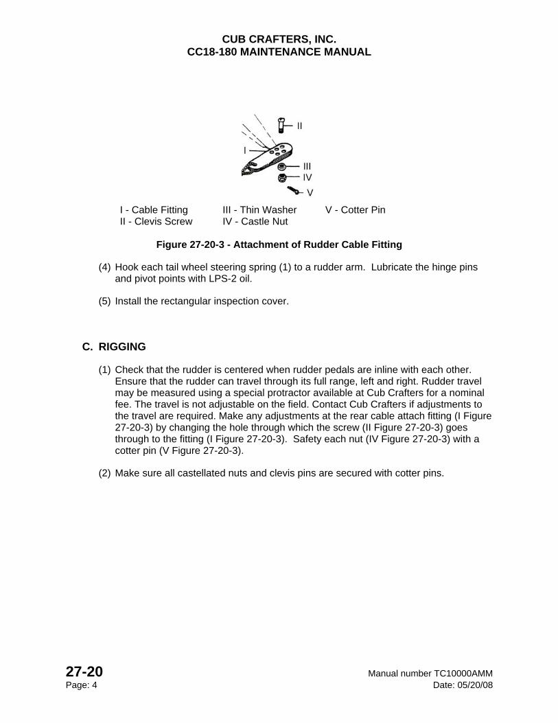
CUB CRAFTERS, INC. CC18-180 MAINTENANCE MANUAL
27-20 Manual number TC10000AMM Page: 4 Date: 05/20/08
I - Cable Fitting III - Thin Washer V - Cotter Pin II - Clevis Screw IV - Castle Nut
Figure 27-20-3 - Attachment of Rudder Cable Fitting
(4) Hook each tail wheel steering spring (1) to a rudder arm. Lubricate the hinge pins and pivot points with LPS-2 oil.
(5) Install the rectangular inspection cover.
C. RIGGING
(1) Check that the rudder is centered when rudder pedals are inline with each other. Ensure that the rudder can travel through its full range, left and right. Rudder travel may be measured using a special protractor available at Cub Crafters for a nominal fee. The travel is not adjustable on the field. Contact Cub Crafters if adjustments to the travel are required. Make any adjustments at the rear cable attach fitting (I Figure 27-20-3) by changing the hole through which the screw (II Figure 27-20-3) goes through to the fitting (I Figure 27-20-3). Safety each nut (IV Figure 27-20-3) with a cotter pin (V Figure 27-20-3).
(2) Make sure all castellated nuts and clevis pins are secured with cotter pins.
CUB CRAFTERS, INC. CC18-180 MAINTENANCE MANUAL
Manual number TC10000AMM 27-20 Date: 05/20/2008 Page 5
3. BALANCING
(1) Insert a 0.25” diameter pin or bolt through each of the hinge holes of the rudder (2 per elevator) such that about 0.25” of the pin or bolt protrude from either side of the hinge.
(2) Place the rudder horizontally over a bench such that the exposed sections of the pins or bolts rest on a half tubes, knife-edges or a similar supports that have little friction and allow the rudder to rotate freely (See Figure 27-20-4).
(3) Place a force gauge or scale at the trailing edge of the elevator, adjacent to the SECOND rib, counting from the bottom of the rudder to the top. Ensure the rudder chord is level. Record the weight.
IF NAVIGATION LIGHT AND TRIM TAB ARE NOT INSTALLED
(4) The weight at the trailing edge must be between 0.93 lb. and 1.32 lb. trailing edge heavy.
IF NAVIGATION LIGHT AND/OR TRIM TAB ARE INSTALLED
(5) The weight at the trailing edge must be between 0.93 lb. and 1.40 lb. trailing edge heavy.
NOTE If the rudder is not within these limits, contact Cub Crafters for disposition.
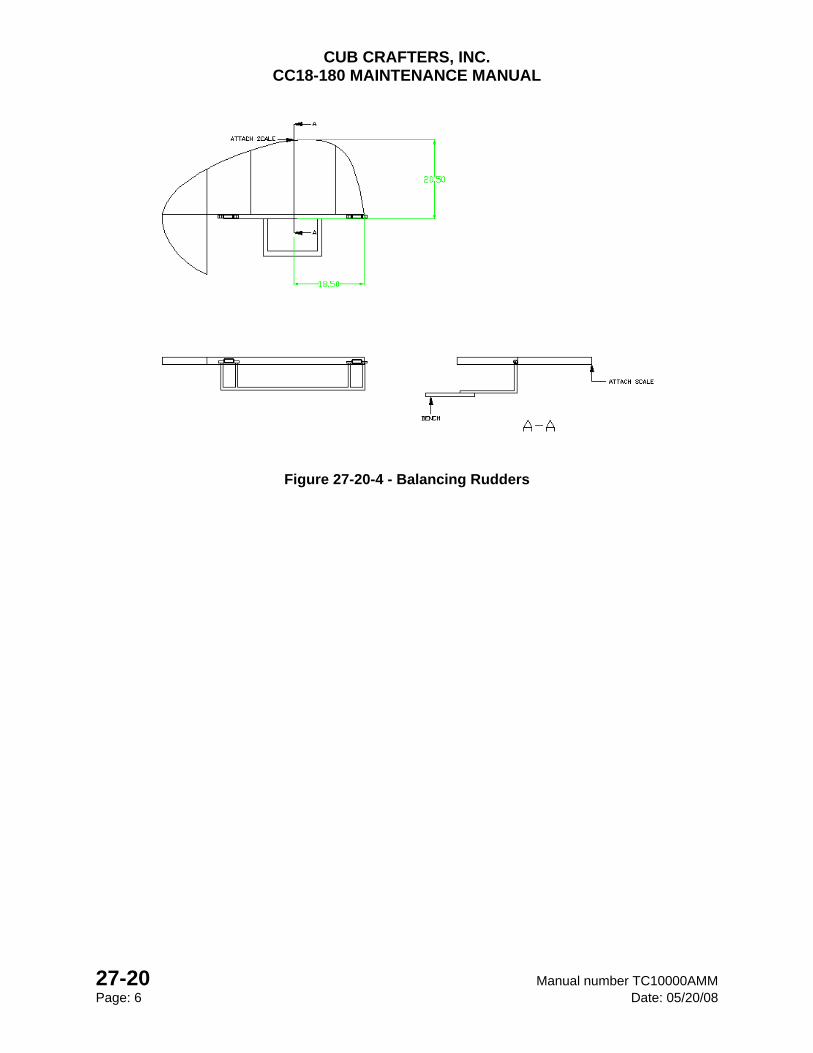
CUB CRAFTERS, INC. CC18-180 MAINTENANCE MANUAL
27-20 Manual number TC10000AMM Page: 6 Date: 05/20/08
Figure 27-20-4 - Balancing Rudders
CUB CRAFTERS, INC. CC18-180 MAINTENANCE MANUAL
Manual number TC10000AMM 27-30 Date: 05/20/08 Page: 1
27-30 ELEVATOR TABLE OF CONTENTS 1. GENERAL ......................................................................................................................... 2
2. MAINTENANCE PRACTICES .......................................................................................... 2
A. REMOVAL ......................................................................................................................... 2
B. INSTALLATION ................................................................................................................. 3
C. RIGGING ........................................................................................................................... 5
3. BALANCING ..................................................................................................................... 6
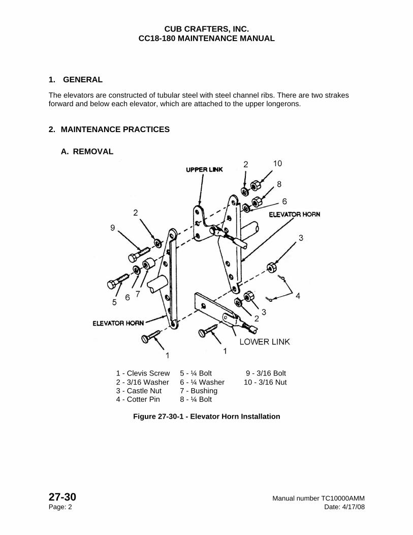
CUB CRAFTERS, INC. CC18-180 MAINTENANCE MANUAL
27-30 Manual number TC10000AMM Page: 2 Date: 4/17/08
1. GENERAL
The elevators are constructed of tubular steel with steel channel ribs. There are two strakes forward and below each elevator, which are attached to the upper longerons.
2. MAINTENANCE PRACTICES
A. REMOVAL
1 - Clevis Screw 5 - ¼ Bolt 9 - 3/16 Bolt 2 - 3/16 Washer 6 - ¼ Washer 10 - 3/16 Nut 3 - Castle Nut 7 - Bushing 4 - Cotter Pin 8 - ¼ Bolt
Figure 27-30-1 - Elevator Horn Installation
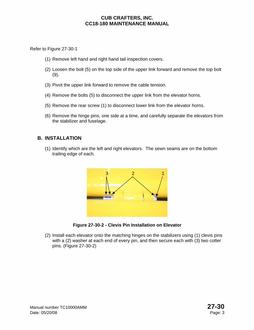
CUB CRAFTERS, INC. CC18-180 MAINTENANCE MANUAL
Manual number TC10000AMM 27-30 Date: 05/20/08 Page: 3
Refer to Figure 27-30-1
(1) Remove left hand and right hand tail inspection covers.
(2) Loosen the bolt (5) on the top side of the upper link forward and remove the top bolt (9).
(3) Pivot the upper link forward to remove the cable tension.
(4) Remove the bolts (5) to disconnect the upper link from the elevator horns.
(5) Remove the rear screw (1) to disconnect lower link from the elevator horns.
(6) Remove the hinge pins, one side at a time, and carefully separate the elevators from the stabilizer and fuselage.
B. INSTALLATION
(1) Identify which are the left and right elevators. The sewn seams are on the bottom trailing edge of each.
Figure 27-30-2 - Clevis Pin Installation on Elevator
(2) Install each elevator onto the matching hinges on the stabilizers using (1) clevis pins with a (2) washer at each end of every pin, and then secure each with (3) two cotter pins. (Figure 27-30-2)
1`
2`
3`
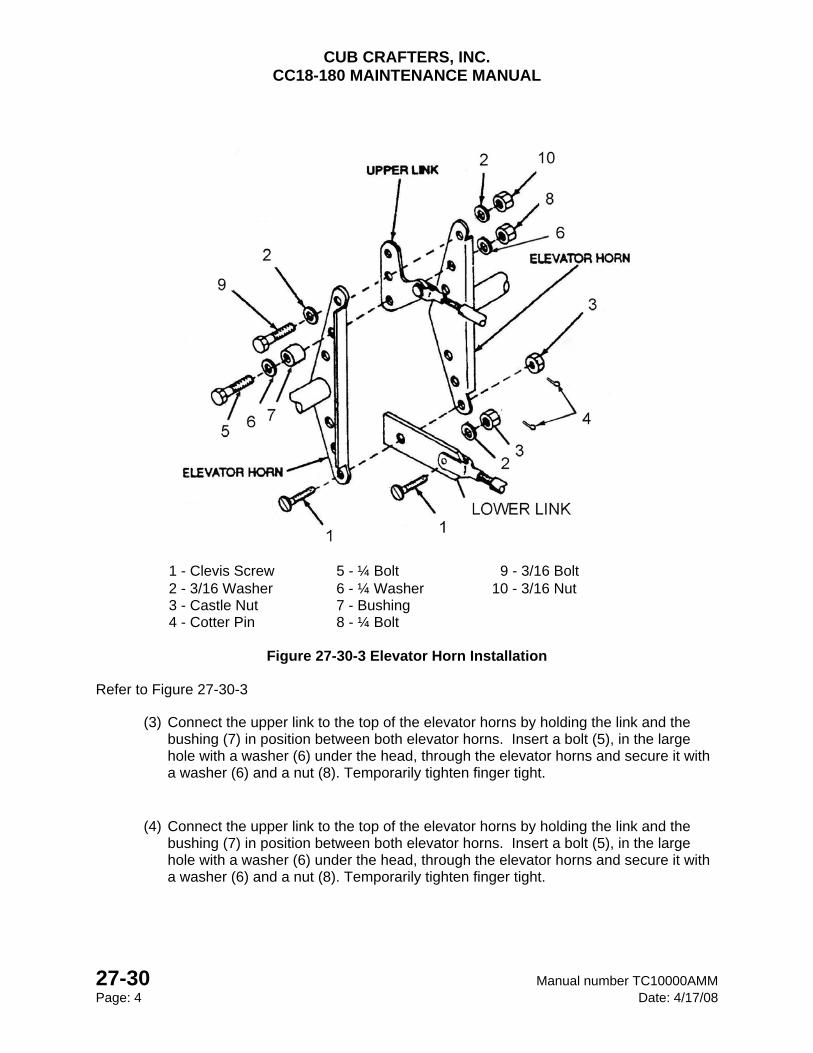
CUB CRAFTERS, INC. CC18-180 MAINTENANCE MANUAL
27-30 Manual number TC10000AMM Page: 4 Date: 4/17/08
1 - Clevis Screw 5 - ¼ Bolt 9 - 3/16 Bolt 2 - 3/16 Washer 6 - ¼ Washer 10 - 3/16 Nut 3 - Castle Nut 7 - Bushing 4 - Cotter Pin 8 - ¼ Bolt
Figure 27-30-3 Elevator Horn Installation
Refer to Figure 27-30-3
(3) Connect the upper link to the top of the elevator horns by holding the link and the bushing (7) in position between both elevator horns. Insert a bolt (5), in the large hole with a washer (6) under the head, through the elevator horns and secure it with a washer (6) and a nut (8). Temporarily tighten finger tight.
(4) Connect the upper link to the top of the elevator horns by holding the link and the bushing (7) in position between both elevator horns. Insert a bolt (5), in the large hole with a washer (6) under the head, through the elevator horns and secure it with a washer (6) and a nut (8). Temporarily tighten finger tight.
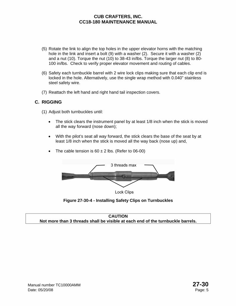
CUB CRAFTERS, INC. CC18-180 MAINTENANCE MANUAL
Manual number TC10000AMM 27-30 Date: 05/20/08 Page: 5
(5) Rotate the link to align the top holes in the upper elevator horns with the matching hole in the link and insert a bolt (9) with a washer (2). Secure it with a washer (2) and a nut (10). Torque the nut (10) to 38-43 in/lbs. Torque the larger nut (8) to 80-100 in/lbs. Check to verify proper elevator movement and routing of cables.
(6) Safety each turnbuckle barrel with 2 wire lock clips making sure that each clip end is locked in the hole. Alternatively, use the single wrap method with 0.040” stainless steel safety wire.
(7) Reattach the left hand and right hand tail inspection covers.
C. RIGGING
(1) Adjust both turnbuckles until:
The stick clears the instrument panel by at least 1/8 inch when the stick is moved all the way forward (nose down);
With the pilot’s seat all way forward, the stick clears the base of the seat by at least 1/8 inch when the stick is moved all the way back (nose up) and,
The cable tension is 60 ± 2 lbs. (Refer to 06-00)
Figure 27-30-4 - Installing Safety Clips on Turnbuckles
CAUTION Not more than 3 threads shall be visible at each end of the turnbuckle barrels.
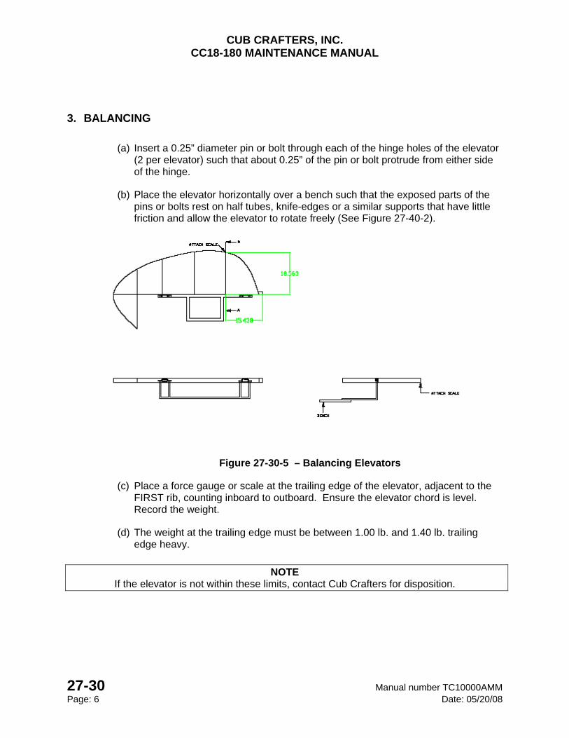
CUB CRAFTERS, INC. CC18-180 MAINTENANCE MANUAL
27-30 Manual number TC10000AMM Page: 6 Date: 05/20/08
3. BALANCING
(a) Insert a 0.25” diameter pin or bolt through each of the hinge holes of the elevator (2 per elevator) such that about 0.25” of the pin or bolt protrude from either side of the hinge.
(b) Place the elevator horizontally over a bench such that the exposed parts of the pins or bolts rest on half tubes, knife-edges or a similar supports that have little friction and allow the elevator to rotate freely (See Figure 27-40-2).
Figure 27-30-5 – Balancing Elevators
(c) Place a force gauge or scale at the trailing edge of the elevator, adjacent to the FIRST rib, counting inboard to outboard. Ensure the elevator chord is level. Record the weight.
(d) The weight at the trailing edge must be between 1.00 lb. and 1.40 lb. trailing edge heavy.
NOTE
If the elevator is not within these limits, contact Cub Crafters for disposition.
CUB CRAFTERS, INC. CC18-180 MAINTENANCE MANUAL
Manual number TC10000AMM 27-31 Date: 05/20/08 Page: 1
27-31 STALL WARNING SYSTEM
TABLE OF CONTENTS 1. GENERAL ............................................................................................................................. 2
2. MAINTENANCE PRACTICES .............................................................................................. 2
A. STALL WARNING SWITCH ADJUSTMENT ..................................................................... 2
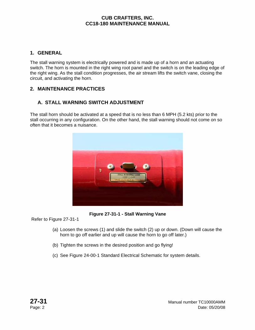
CUB CRAFTERS, INC. CC18-180 MAINTENANCE MANUAL
27-31 Manual number TC10000AMM Page: 2 Date: 05/20/08
1. GENERAL
The stall warning system is electrically powered and is made up of a horn and an actuating switch. The horn is mounted in the right wing root panel and the switch is on the leading edge of the right wing. As the stall condition progresses, the air stream lifts the switch vane, closing the circuit, and activating the horn.
2. MAINTENANCE PRACTICES
A. STALL WARNING SWITCH ADJUSTMENT The stall horn should be activated at a speed that is no less than 6 MPH (5.2 kts) prior to the stall occurring in any configuration. On the other hand, the stall warning should not come on so often that it becomes a nuisance.
Figure 27-31-1 - Stall Warning Vane Refer to Figure 27-31-1
(a) Loosen the screws (1) and slide the switch (2) up or down. (Down will cause the horn to go off earlier and up will cause the horn to go off later.)
(b) Tighten the screws in the desired position and go flying!
(c) See Figure 24-00-1 Standard Electrical Schematic for system details.
CUB CRAFTERS, INC. CC18-180 MAINTENANCE MANUAL
Manual number TC10000AMM 27-40 Date: 05/20/08 Page 1
27-40 HORIZONTAL STABILIZERS TABLE OF CONTENTS
1. GENERAL ................................................................................................................................ 2
2. MAINTANENCE PRACTICES .................................................................................................. 2
A. REMOVAL ...................................................................................................................... 2
B. INSTALLATION .............................................................................................................. 3
(1) RIGHT HORIZONTAL STABILIZER ........................................................................... 3
(2) LEFT HORIZONTAL STABILIZER ............................................................................. 5
(3) TAIL BRACE WIRES .................................................................................................. 6
C. RIGGING OF TAIL BRACE WIRES ............................................................................... 8
3. RIGGING THE STABILIZER TRIM .......................................................................................... 8
A. DESCRIPTION ............................................................................................................... 8
B. RIGGING ........................................................................................................................ 9
C. STRAKES ..................................................................................................................... 12
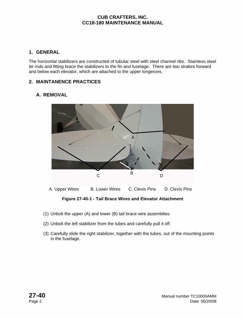
CUB CRAFTERS, INC. CC18-180 MAINTENANCE MANUAL
27-40 Manual number TC10000AMM Page 2 Date: 05/20/08
1. GENERAL
The horizontal stabilizers are constructed of tubular steel with steel channel ribs. Stainless steel tie rods and fitting brace the stabilizers to the fin and fuselage. There are two strakes forward and below each elevator, which are attached to the upper longerons.
2. MAINTANENCE PRACTICES
A. REMOVAL
A. Upper Wires B. Lower Wires C. Clevis Pins D. Clevis Pins
Figure 27-40-1 - Tail Brace Wires and Elevator Attachment
(1) Unbolt the upper (A) and lower (B) tail brace wire assemblies.
(2) Unbolt the left stabilizer from the tubes and carefully pull it off.
(3) Carefully slide the right stabilizer, together with the tubes, out of the mounting points in the fuselage.
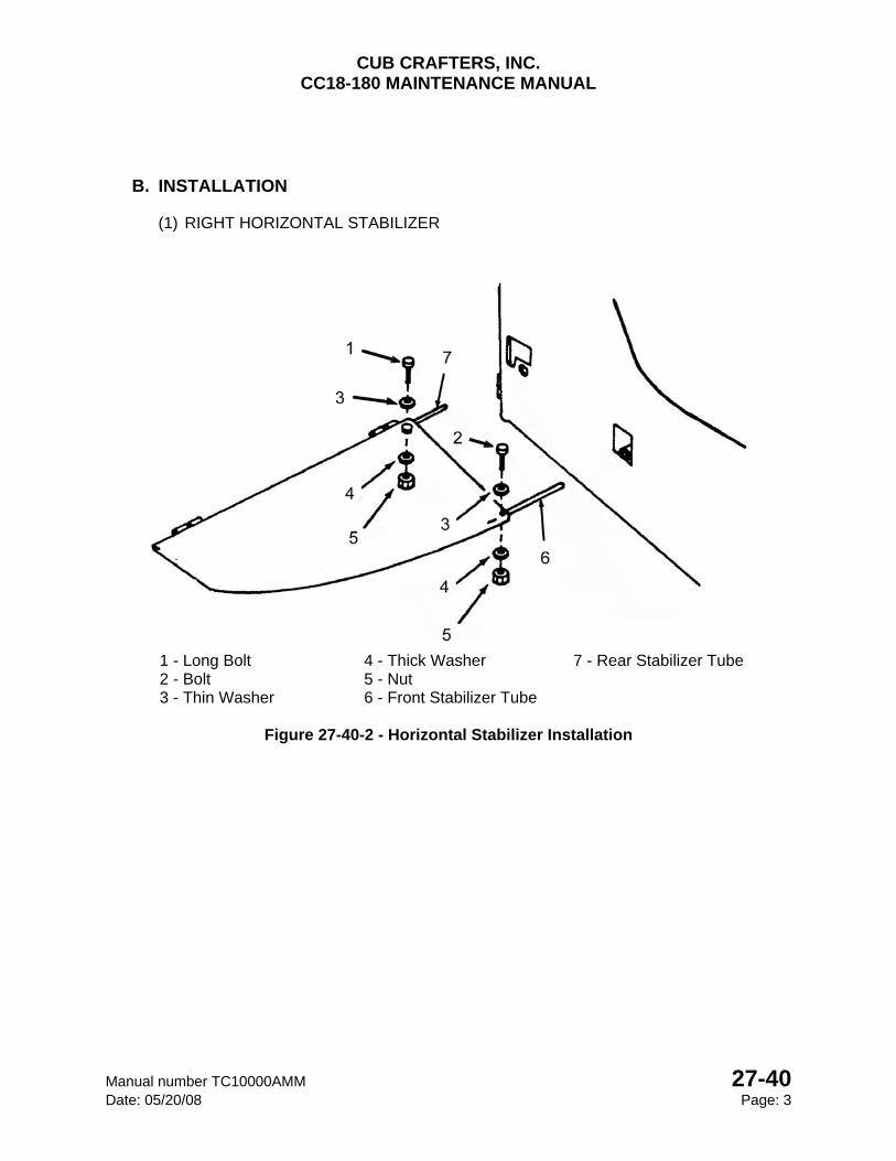
CUB CRAFTERS, INC. CC18-180 MAINTENANCE MANUAL
Manual number TC10000AMM 27-40 Date: 05/20/08 Page: 3
B. INSTALLATION
(1) RIGHT HORIZONTAL STABILIZER
1 - Long Bolt 4 - Thick Washer 7 - Rear Stabilizer Tube2 - Bolt 5 - Nut 3 - Thin Washer 6 - Front Stabilizer Tube
Figure 27-40-2 - Horizontal Stabilizer Installation
CUB CRAFTERS, INC. CC18-180 MAINTENANCE MANUAL
27-40 Manual number TC10000AMM Page: 4 Date: 05/20/08
Refer to Figure 27-40-2
(a) Identify the right stabilizer. (Note that the fabric seam should be on the bottom of the surface). Lay the stabilizer on a suitable work surface and apply a thin coat of grease (MIL-G-81322E) to the inside ends of the front and rear tubes.
(b) If the tail surfaces have been changed and new tubes are to be installed, complete the following steps;
Make a line around the front stabilizer tube (6), 2-7/8 inches from one end with a fine tip felt pen.
Make a line around the rear stabilizer tube (7), 2-1/2 inches from one end with a fine tip felt pen.
Slide the front tube liner (6) into the end of the stabilizer until the marks are even with the end of the stabilizer tube.
Drill a hole down through the topside of the stabilizer and tube with a #12 bit, using the predrilled hole in the stabilizer frame as a guide. DO NOT DRILL CLEAR THROUGH AT THIS TIME.
Insert a short 3/16-inch bolt or cleco into each hole to hold the alignment and turn the stabilizer frame over. It may be may be necessary to hold the alignment bolt in place with tape.
Drill a hole with a #12 bit through the stabilizer holes into the tube liners, remove the alignment bolts and drill clear through to "clean out" the holes.
Repeat the same steps for the rear tube liner (7).
(c) Attach the front tube with a long bolt (1) and washer (3) inserted through the stabilizer and tube (6) and secure it with a washer (4) and nut (5). Torque the nut to 38-43 in/lbs.
(d) Attach the rear tube with a bolt (2) and washer (3) inserted through the stabilizer and tube and secure it with a washer (4) and nut (5). Torque the nut to 38-43 in/lbs.
(e) Apply a thin coat of grease (MIL-G-81322E) to the inside of the stabilizer attachment tubes on the airframe and slide the stabilizer on until it is tight against the mounting points.
CUB CRAFTERS, INC. CC18-180 MAINTENANCE MANUAL
Manual number TC10000AMM 27-40 Date: 05/20/08 Page: 5
(2) LEFT HORIZONTAL STABILIZER
(a) Apply grease (MIL-G-81322E) to the inside of the front and rear tubes of the right stabilizer and install it onto the ends of the tubes that protrude from the side of the fuselage. It may be necessary to have a second person hold the left stabilizer as a back up.
(b) Make sure the sewn seams on the trailing edge of both stabilizers are on the bottom.
(c) Make sure the stabilizer frame fits tightly against the fuselage attachments.
(d) If the tail surfaces have been changed and new tube liners are installed complete the following;
Have a second person pull the front corners of the stabilizer together tight against the fuselage attachment yoke then drill a hole down through predrilled hole in top of the left front stabilizer tube into the tube liner with a #12 bit. DO NOT DRILL CLEAR THROUGH.
If any play exists between stabilizer and the fuselage use a tapered punch to adjust the alignment of the upper hole and remove the play; drill the hole up from the bottom through the stabilizer and liners and on up through the top to "clean out" the holes.
(e) Attach with a long bolt (1) and washer (3) inserted down through the stabilizer and tube (6) and secure it with a washer (4) and nut (5). Torque the nut to 38-43 in/lbs.
(f) After the tail brace wires are installed and rigged, drill the right rear stabilizer and tube with a #12 bit and insert a bolt (2) and washer (3) and secure with a washer (P4) and nut (5). Torque the nut to 38-43 in/lbs.
(g) Pump grease (MIL-G-81322E) into the stabilizer link assembly grease fittings until it starts to squeeze out.
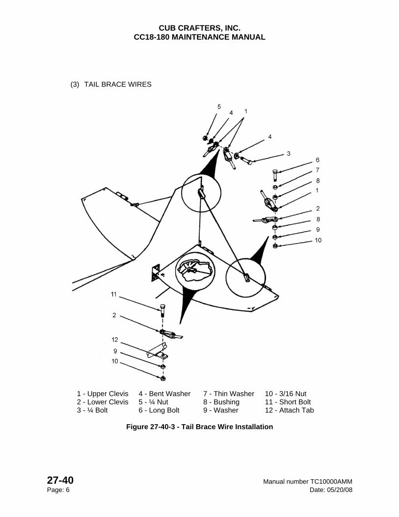
CUB CRAFTERS, INC. CC18-180 MAINTENANCE MANUAL
27-40 Manual number TC10000AMM Page: 6 Date: 05/20/08
(3) TAIL BRACE WIRES
1 - Upper Clevis 4 - Bent Washer 7 - Thin Washer 10 - 3/16 Nut 2 - Lower Clevis 5 - ¼ Nut 8 - Bushing 11 - Short Bolt 3 - ¼ Bolt 6 - Long Bolt 9 - Washer 12 - Attach Tab
Figure 27-40-3 - Tail Brace Wire Installation
CUB CRAFTERS, INC. CC18-180 MAINTENANCE MANUAL
Manual number TC10000AMM 27-40 Date: 05/20/08 Page: 7
Refer to Figure 27-40-3
(a) Set the tail of the aircraft on a sawhorse or a bench.
(b) Position a long tail wire with the most sharply bent clevis (1) on the fin and insert a bolt (3) with a bent washer (4).
(c) On the opposite side of the fin, install the other long tail wire with the most sharply bent clevis (1) at the top; insert the bolt and secure with a bent washer (4) and nut (5) and torque to 80-100 in/lbs.
(d) Line up the clevis (1) that is on the lower end of a long wire with the hole in the rear spar of the horizontal stabilizer.
(e) Insert a bolt (6) with a washer (7) and bushing (8) through the clevis (2).
(f) Position a short tail wire, with the bent clevis (2) through the bolt that was just inserted through the rear spar of the horizontal stabilizer. Secure with a washer (9), bushing (8) and nut (10) and torque to 38-43 in/lbs.
(g) Line up the clevis (2) on the lower end of the wire with the hole in the tab that is on the bottom, rear end the fuselage (12). Be sure that the tab on the fuselage (12) is sandwiched between the two surfaces of the clevis (2).
(h) Insert a bolt (11) and secure with a washer (9) and nut (10) and torque to 38-43 in/lbs.
(i) Repeat on the opposite side.
CUB CRAFTERS, INC. CC18-180 MAINTENANCE MANUAL
27-40 Manual number TC10000AMM Page: 8 Date: 05/20/08
C. RIGGING OF TAIL BRACE WIRES
(1) Set the tail of the aircraft on a sawhorse or bench.
(2) Level the fuselage laterally (Refer to Section 08-00).
(3) Hang a plumb bob from the top rudder hinge and line up the tip with the bottom rudder hinge.
(4) If needed, adjust the tension of the tail brace wires to straighten the fin. Accomplish this by loosening the jam nut on either end of the wire and turn the brass barrel, (in to shorten the wire and out to lengthen it).
(5) The tail brace wires must be tensioned while at the same time ensuring that the horizontal stabilizers remain horizontal and the fin vertical.
(6) Lay a level along the rear spar of the stabilizers.
(7) Adjust the tension of the tail brace wires such that a 0.44 (7/16) inches ± 0.0625 (1/16) inches deflection may be reached when applying a load of 10 ±1 lbs at right angles at the center of either of the top wires.
(8) Ensure that the rear spar of the stabilizer ends up level and the fin remains vertical at the rudder hinge centerline after tensioning.
(9) The tolerance is ± 0.5 degrees.
(10) Tighten all 8 jam nuts on the brass barrels.
3. RIGGING THE STABILIZER TRIM
A. DESCRIPTION The CC18 is trimmed in flight by changing the stabilizer’s angle of incidence. A crank on the left side of the cockpit operates the stabilizer trim control. A circular flexible steel cable passes around a pulley attached to the crank, then back through the fuselage to another pulley on the lower end of the stabilizer adjusting a jackscrew. When the crank is rotated, the jackscrew turns raising or lowering the leading edge of the horizontal stabilizers.
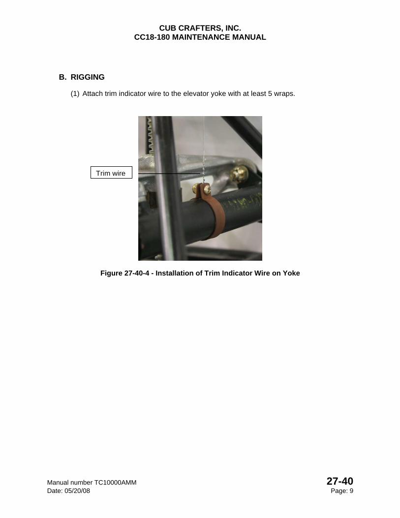
CUB CRAFTERS, INC. CC18-180 MAINTENANCE MANUAL
Manual number TC10000AMM 27-40 Date: 05/20/08 Page: 9
B. RIGGING
(1) Attach trim indicator wire to the elevator yoke with at least 5 wraps.
Figure 27-40-4 - Installation of Trim Indicator Wire on Yoke
Trim wire
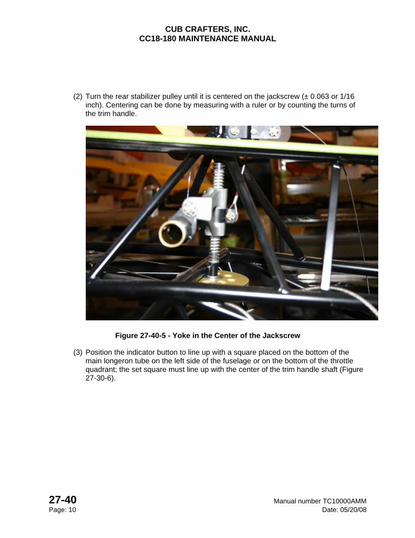
CUB CRAFTERS, INC. CC18-180 MAINTENANCE MANUAL
27-40 Manual number TC10000AMM Page: 10 Date: 05/20/08
(2) Turn the rear stabilizer pulley until it is centered on the jackscrew (± 0.063 or 1/16 inch). Centering can be done by measuring with a ruler or by counting the turns of the trim handle.
Figure 27-40-5 - Yoke in the Center of the Jackscrew
(3) Position the indicator button to line up with a square placed on the bottom of the main longeron tube on the left side of the fuselage or on the bottom of the throttle quadrant; the set square must line up with the center of the trim handle shaft (Figure 27-30-6).
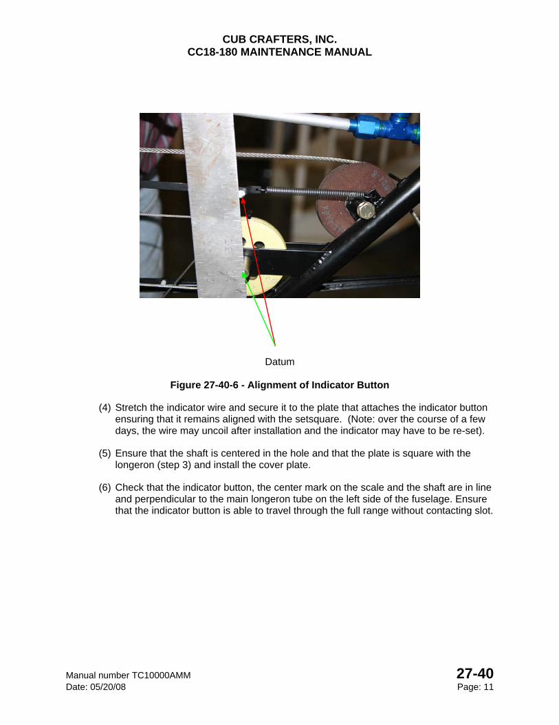
CUB CRAFTERS, INC. CC18-180 MAINTENANCE MANUAL
Manual number TC10000AMM 27-40 Date: 05/20/08 Page: 11
Datum
Figure 27-40-6 - Alignment of Indicator Button
(4) Stretch the indicator wire and secure it to the plate that attaches the indicator button ensuring that it remains aligned with the setsquare. (Note: over the course of a few days, the wire may uncoil after installation and the indicator may have to be re-set).
(5) Ensure that the shaft is centered in the hole and that the plate is square with the longeron (step 3) and install the cover plate.
(6) Check that the indicator button, the center mark on the scale and the shaft are in line and perpendicular to the main longeron tube on the left side of the fuselage. Ensure that the indicator button is able to travel through the full range without contacting slot.
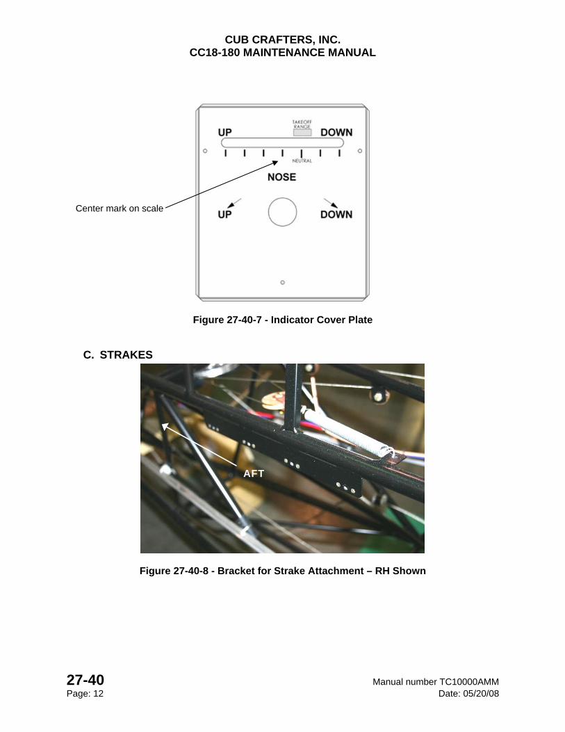
CUB CRAFTERS, INC. CC18-180 MAINTENANCE MANUAL
27-40 Manual number TC10000AMM Page: 12 Date: 05/20/08
Figure 27-40-7 - Indicator Cover Plate
C. STRAKES
Figure 27-40-8 - Bracket for Strake Attachment – RH Shown
Center mark on scale
AFT
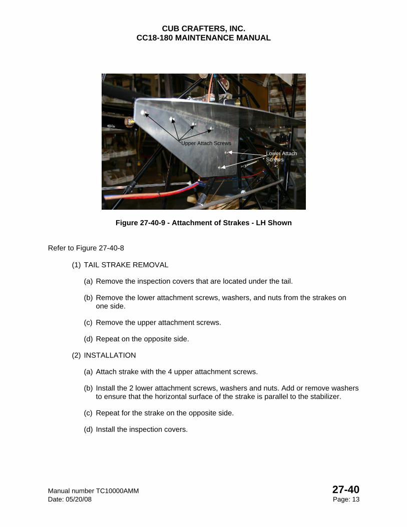
CUB CRAFTERS, INC. CC18-180 MAINTENANCE MANUAL
Manual number TC10000AMM 27-40 Date: 05/20/08 Page: 13
Figure 27-40-9 - Attachment of Strakes - LH Shown Refer to Figure 27-40-8
(1) TAIL STRAKE REMOVAL
(a) Remove the inspection covers that are located under the tail.
(b) Remove the lower attachment screws, washers, and nuts from the strakes on one side.
(c) Remove the upper attachment screws.
(d) Repeat on the opposite side.
(2) INSTALLATION
(a) Attach strake with the 4 upper attachment screws.
(b) Install the 2 lower attachment screws, washers and nuts. Add or remove washers to ensure that the horizontal surface of the strake is parallel to the stabilizer.
(c) Repeat for the strake on the opposite side.
(d) Install the inspection covers.
Upper Attach Screws
Lower Attach Screws

CUB CRAFTERS, INC. CC18-180 MAINTENANCE MANUAL
27-40 Manual number TC10000AMM Page: 14 Date: 05/20/08
INTENTIONALLY LEFT BLANK
CUB CRAFTERS
CC18-180 MAINTENANCE MANUAL
Manual number TC10000AMM 27-50 Date: 04/15/05 Page 1
27-50 FLAPS
Table of Contents
1
1. GENERAL .......................................................................................................................... 2
2. MAINTENANCE PRACTICES ........................................................................................... 2
(1) REMOVAL .................................................................................................................. 2
(2) INSTALLATION .......................................................................................................... 3
(3) RIGGING THE POSITION OF THE FLAPS ................................................................ 4
(4) RIGGING THE FLAP TRAVEL .................................................................................... 5
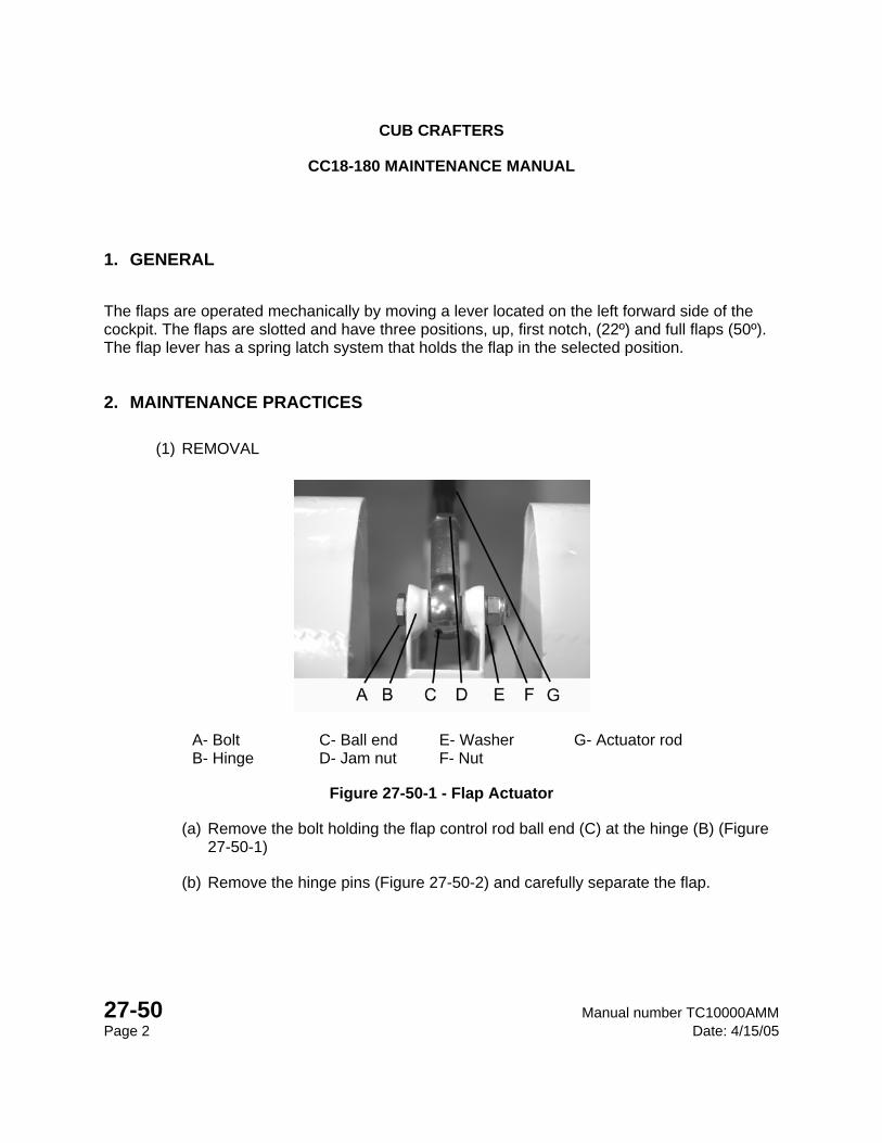
CUB CRAFTERS
CC18-180 MAINTENANCE MANUAL
27-50 Manual number TC10000AMM Page 2 Date: 4/15/05
1. GENERAL
The flaps are operated mechanically by moving a lever located on the left forward side of the cockpit. The flaps are slotted and have three positions, up, first notch, (22º) and full flaps (50º). The flap lever has a spring latch system that holds the flap in the selected position.
2. MAINTENANCE PRACTICES
(1) REMOVAL
A- Bolt C- Ball end E- Washer G- Actuator rod B- Hinge D- Jam nut F- Nut
Figure 27-50-1 - Flap Actuator
(a) Remove the bolt holding the flap control rod ball end (C) at the hinge (B) (Figure 27-50-1)
(b) Remove the hinge pins (Figure 27-50-2) and carefully separate the flap.
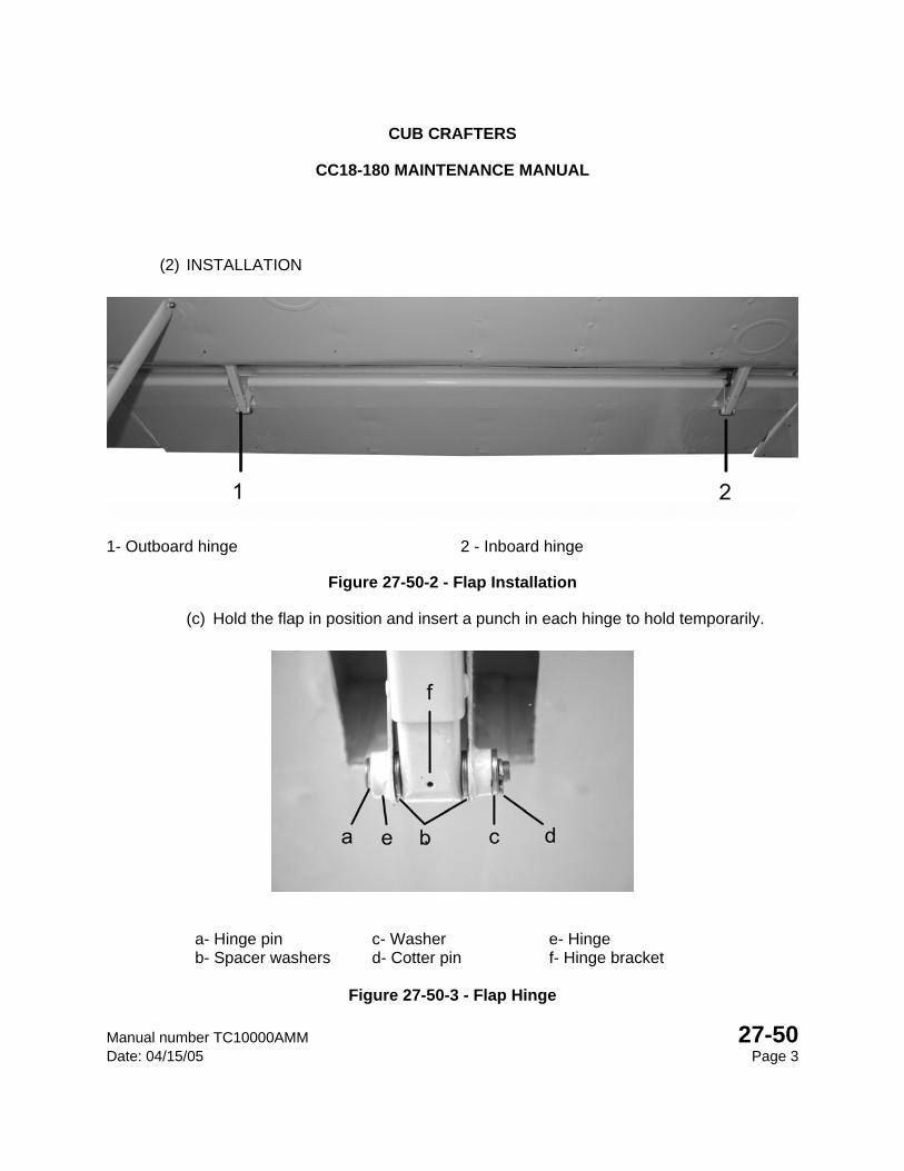
CUB CRAFTERS
CC18-180 MAINTENANCE MANUAL
Manual number TC10000AMM 27-50 Date: 04/15/05 Page 3
(2) INSTALLATION
1- Outboard hinge 2 - Inboard hinge
Figure 27-50-2 - Flap Installation
(c) Hold the flap in position and insert a punch in each hinge to hold temporarily.
a- Hinge pin c- Washer e- Hinge b- Spacer washers d- Cotter pin f- Hinge bracket
Figure 27-50-3 - Flap Hinge
CUB CRAFTERS
CC18-180 MAINTENANCE MANUAL
27-50 Manual number TC10000AMM Page 4 Date: 4/15/05
Reference Figure 27-50-3
(d) At the inboard hinge (2 Figure 27-50-2) insert a hinge pin (a), pointing inboard, through the hinge (e), spacer washer (b) hinge bracket (f), spacer washer (b), hinge (e) and washer (c) Secure with a cotter pin (d).
(e) At the outboard hinge (1 Figure 27-50-2) fill any gap between the hinge (e) and hinge bracket (f) with a thin or thick spacer washer as necessary.
(f) Insert a hinge pin (a), pointing inboard, through the hinge (e), hinge bracket (f), hinge (e) and washer (c). Secure with a cotter pin (d).
(g) At the inboard hinge (2 Figure 27-50-2) align the flap control rod ball end (C Figure 27-50-1) with the hinge (B Figure 27-50-1) attach point.
(h) Insert the bolt (A Figure 27-50-1) through the hinge (B) and ball end (C Figure 27-50-1) then secure with a washer (E Figure 27-50-1) and nut (F Figure 27-50-1) torqued to 38-43 in/lbs.
NOTE
It may be necessary to check the flap rigging depending on the parts that were removed.
(3) RIGGING THE POSITION OF THE FLAPS
(a) Position the flaps in the “UP” position.
(b) Place a straightedge along the bottom of the wing at a position mid span along the flap. The bottom surface of the flap should line up with the bottom of the wing.
(c) To adjust, unbolt the flap actuator rod ball end from the flap hinge. Loosen the jam nut (D Figure 27-50-1) and screw the ball end (C Figure 27-50-1) in or out accordingly. Ensure that both flaps are aligned.
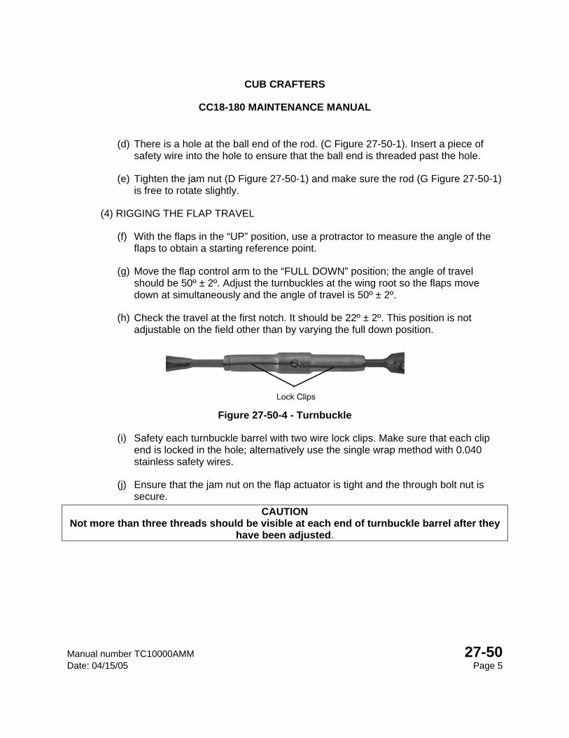
CUB CRAFTERS
CC18-180 MAINTENANCE MANUAL
Manual number TC10000AMM 27-50 Date: 04/15/05 Page 5
(d) There is a hole at the ball end of the rod. (C Figure 27-50-1). Insert a piece of safety wire into the hole to ensure that the ball end is threaded past the hole.
(e) Tighten the jam nut (D Figure 27-50-1) and make sure the rod (G Figure 27-50-1) is free to rotate slightly.
(4) RIGGING THE FLAP TRAVEL
(f) With the flaps in the “UP” position, use a protractor to measure the angle of the flaps to obtain a starting reference point.
(g) Move the flap control arm to the “FULL DOWN” position; the angle of travel should be 50º ± 2º. Adjust the turnbuckles at the wing root so the flaps move down at simultaneously and the angle of travel is 50º ± 2º.
(h) Check the travel at the first notch. It should be 22º ± 2º. This position is not adjustable on the field other than by varying the full down position.
Figure 27-50-4 - Turnbuckle
(i) Safety each turnbuckle barrel with two wire lock clips. Make sure that each clip end is locked in the hole; alternatively use the single wrap method with 0.040 stainless safety wires.
(j) Ensure that the jam nut on the flap actuator is tight and the through bolt nut is secure.
CAUTION Not more than three threads should be visible at each end of turnbuckle barrel after they
have been adjusted.
CUB CRAFTERS
CC18-180 MAINTENANCE MANUAL
27-50 Manual number TC10000AMM Page 6 Date: 4/15/05
INTENTIONALLY LEFT BLANK

CHAPTER
28-00
FUEL SYSTEM

CUB CRAFTERS, INC. CC18-180 MAINTENANCE MANUAL
Manual number TC10000AMM 28-00 Date: 04/16/08 Page: 1
28-00 FUEL SYSTEM
TABLE OF CONTENTS 1. GENERAL ............................................................................................................................. 2
2. TROUBLESHOOTING .......................................................................................................... 4
3. MAINTENANCE PRACTICES .............................................................................................. 4
A. TANK REMOVAL .............................................................................................................. 4
(1) REMOVAL .................................................................................................................... 4
(2) INSPECTION ................................................................................................................ 4
(3) TANK REPAIR .............................................................................................................. 5
(4) INSTALLATION ............................................................................................................ 5
B. SERVICING FILTERS ...................................................................................................... 6
(1) FUEL STRAINER SERVICING ..................................................................................... 6
(2) CARBURETOR INLET SCREEN SERVICING ............................................................. 7
C. FUEL SELECTOR ............................................................................................................ 8
(1) FUEL SELECTOR OVERHAUL.................................................................................... 8
D. FUEL CHECK VALVE .................................................................................................... 10
(1) FUEL VENT CHECK VALVE OVERHAUL ................................................................. 10
CUB CRAFTERS, INC. CC18-180 MAINTENANCE MANUAL
28-00 Manual number TC10000AMM Page: 2 Date: 04/16/08
1. GENERAL
The fuel system is a gravity flow system. Fuel drains from two wing tanks through a selector valve and fuel strainer to the carburetor. There is an engine fuel primer system that may be used to start the engine, especially in cold conditions. The fuel primer draws fuel from the strainer by means of a hand-operated pump on the instrument panel and injects it into three cylinders for starting. The selector valve is located on the lower left side of the cockpit and has four positions;
Both - The engine is fed by both fuel tanks Left - Fuel is supplied by the left tank. Right - Fuel is supplied by the right tank. Off - Fuel supply to the engine is cut off.
Fuel will flow from one tank to the other when the selector is in either the “OFF” or the “BOTH” position. The fuel vent lines are fitted with check valves, which will prevent fuel from being discharged when tanks are full and the aircraft is in uncoordinated flight or when it is parked on a slope. When parking the aircraft on a slope, leave the selector either in the “LEFT” or “RIGHT” positions to prevent fuel from flowing from one tank to the other. The engine may be operated in the BOTH, LEFT, or RIGHT positions. However, the selector must be in the “BOTH” position for takeoff and landing. The fuel strainer is equipped with a quick drain and is mounted on the engine side of the firewall. Fuel quantity is determined by means of two glass sight gauges located on either side of the cockpit at the wing root. The tanks are ventilated through tubes at the forward outboard edge of the tanks. The tubes protrude under the wing, close to the forward wing strut attachment. Also an interconnect vent line goes between them crossing behind the rear spar carry through. Prior to refueling the aircraft, connect the fueling equipment’s grounding wire to either of the wing tie downs
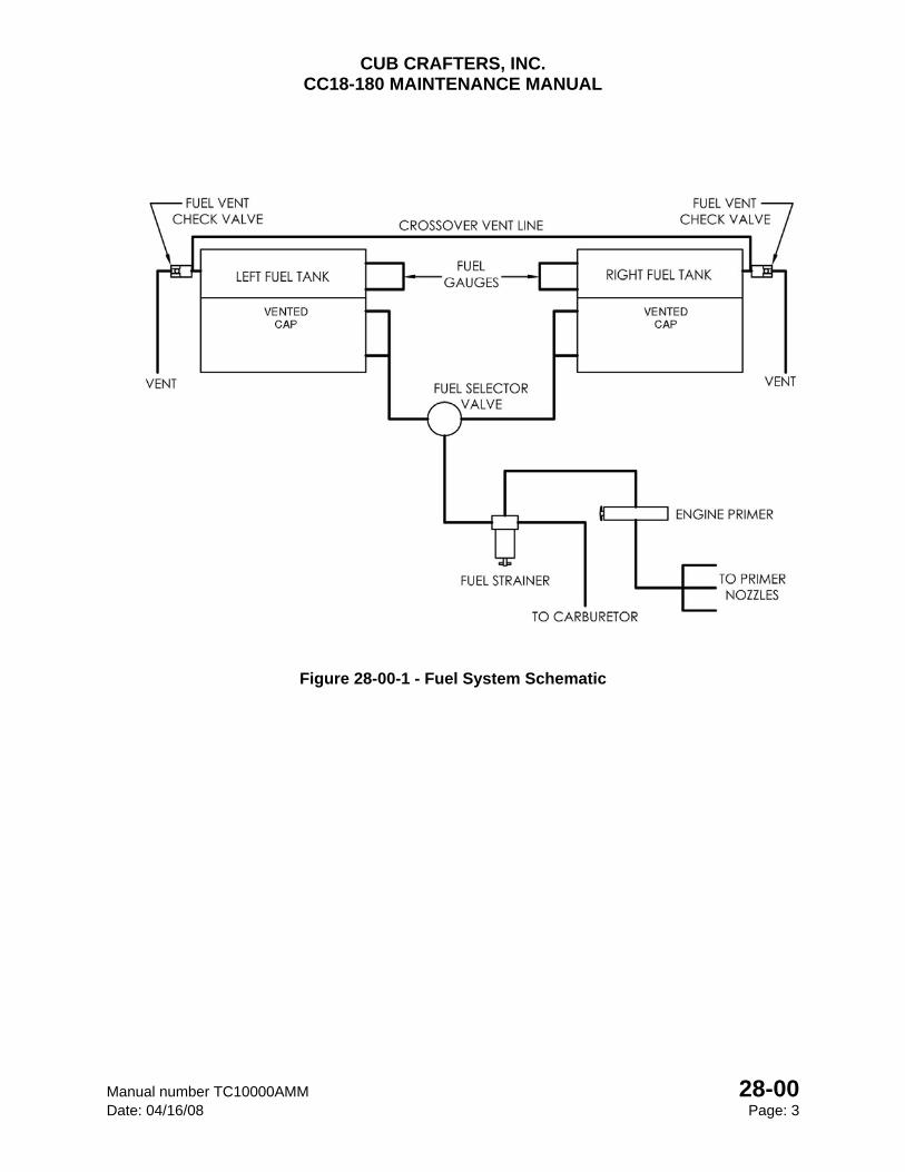
CUB CRAFTERS, INC. CC18-180 MAINTENANCE MANUAL
Manual number TC10000AMM 28-00 Date: 04/16/08 Page: 3
Figure 28-00-1 - Fuel System Schematic
CUB CRAFTERS, INC. CC18-180 MAINTENANCE MANUAL
28-00 Manual number TC10000AMM Page: 4 Date: 04/16/08
2. TROUBLESHOOTING
PROBLEM PROBABLE CAUSE REMEDY
Filler Cap Leaks Filler Cap Improperly Installed Install Filler Cap Properly Seal Improperly Installed Replace Fuel Cap Seal Deteriorated Seal Replace Fuel Cap Seal
Leak in Fuel Line Loose Connector(s) Inspect and Tighten Connector(s) Chaffing Replace Fuel Line Defective Thread Replace Threaded Component
Fuel Discharge From Vents Defective Fuel Check Valve Clean Fuel Check Valve, Reassemble, or Replace
3. MAINTENANCE PRACTICES
A. TANK REMOVAL
(1) REMOVAL
(a) Drain the fuel tanks through the drains located on the underside of the wing.
(b) Remove the fuel tank covers.
(c) Remove the front, the upper and the lower wing root-fairing panels.
(d) Disconnect the supply and fuel vent check valve from the tank.
(e) Remove the nipple fittings from the tank.
(f) Unfasten the fuel tank straps.
(g) Unfasten the drag brace tube at the inboard end.
(h) Carefully lift the tank out of the tank bay allowing the drag tube to pivot at the outboard end.
(2) INSPECTION
(a) Visual inspect for damage, leaks and distortion.
CUB CRAFTERS, INC. CC18-180 MAINTENANCE MANUAL
Manual number TC10000AMM 28-00 Date: 04/16/08 Page: 5
(3) TANK REPAIR
(a) Thoroughly clean the tank inside and outside. Ensure that any residual fuel fumes have completely dissipated.
(b) The tank may be repaired by welding the affected area. This must be carried out by a qualified repair shop or by Cub Crafters, Inc.
(c) After repairing, a pressure test of the tank should be carried out. Using shop air, apply 1.5 to 2 psi to the tank and ensure that the pressure can be maintained for 5 minutes.
(4) INSTALLATION
(a) Carefully insert the drag brace through the tank and lower the tank into the bay.
(b) Reconnect the drag brace tube at the inboard end and tighten the nut.
(c) Refasten the fuel tank straps and tighten until the strap slack is removed.
(d) Lubricate the fuel nipple fittings with EZ TURN Lubricant, insert in the tank and tighten.
(e) Reconnect the fuel supply and fuel vent check valve. Make sure all the nipple fittings and hose clamps are tight.
(f) Install the upper, the lower and the front wing root fairings.
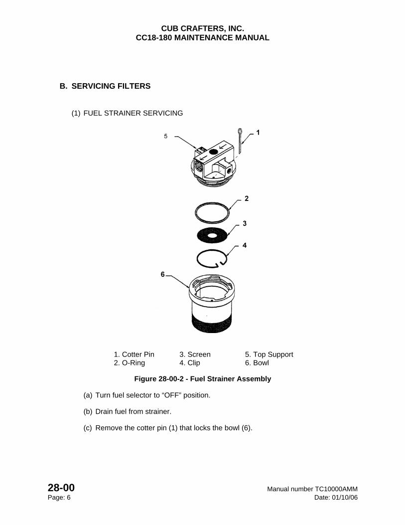
CUB CRAFTERS, INC. CC18-180 MAINTENANCE MANUAL
28-00 Manual number TC10000AMM Page: 6 Date: 01/10/06
B. SERVICING FILTERS
(1) FUEL STRAINER SERVICING
1. Cotter Pin 3. Screen 5. Top Support 2. O-Ring 4. Clip 6. Bowl
Figure 28-00-2 - Fuel Strainer Assembly
(a) Turn fuel selector to “OFF” position.
(b) Drain fuel from strainer.
(c) Remove the cotter pin (1) that locks the bowl (6).
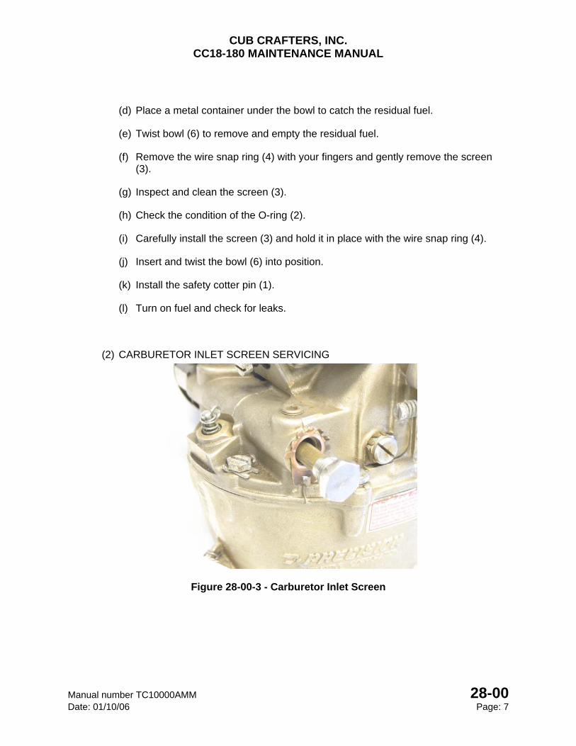
CUB CRAFTERS, INC. CC18-180 MAINTENANCE MANUAL
Manual number TC10000AMM 28-00 Date: 01/10/06 Page: 7
(d) Place a metal container under the bowl to catch the residual fuel.
(e) Twist bowl (6) to remove and empty the residual fuel.
(f) Remove the wire snap ring (4) with your fingers and gently remove the screen (3).
(g) Inspect and clean the screen (3).
(h) Check the condition of the O-ring (2).
(i) Carefully install the screen (3) and hold it in place with the wire snap ring (4).
(j) Insert and twist the bowl (6) into position.
(k) Install the safety cotter pin (1).
(l) Turn on fuel and check for leaks.
(2) CARBURETOR INLET SCREEN SERVICING
Figure 28-00-3 - Carburetor Inlet Screen
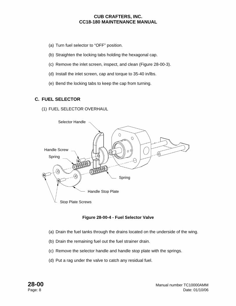
CUB CRAFTERS, INC. CC18-180 MAINTENANCE MANUAL
28-00 Manual number TC10000AMM Page: 8 Date: 01/10/06
(a) Turn fuel selector to “OFF” position.
(b) Straighten the locking tabs holding the hexagonal cap.
(c) Remove the inlet screen, inspect, and clean (Figure 28-00-3).
(d) Install the inlet screen, cap and torque to 35-40 in/lbs.
(e) Bend the locking tabs to keep the cap from turning.
C. FUEL SELECTOR
(1) FUEL SELECTOR OVERHAUL
Figure 28-00-4 - Fuel Selector Valve
(a) Drain the fuel tanks through the drains located on the underside of the wing.
(b) Drain the remaining fuel out the fuel strainer drain.
(c) Remove the selector handle and handle stop plate with the springs.
(d) Put a rag under the valve to catch any residual fuel.
Selector Handle
Handle Screw
Spring
Spring
Handle Stop Plate
Stop Plate Screws
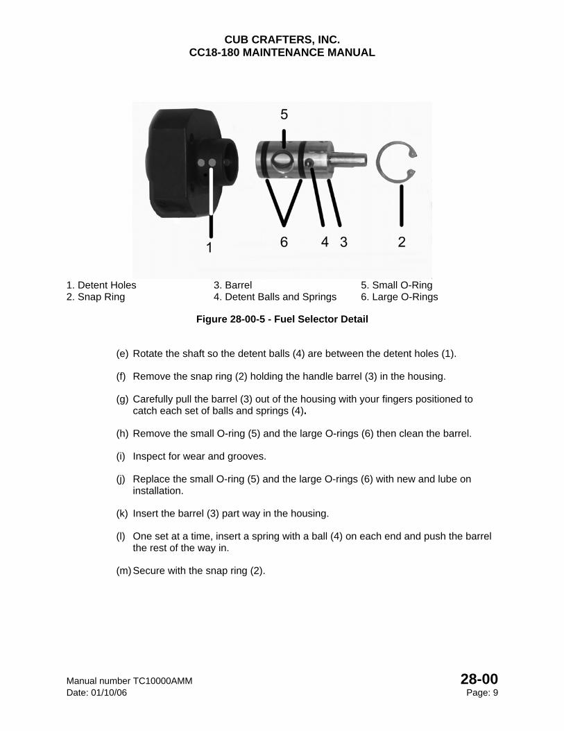
CUB CRAFTERS, INC. CC18-180 MAINTENANCE MANUAL
Manual number TC10000AMM 28-00 Date: 01/10/06 Page: 9
1. Detent Holes 3. Barrel 5. Small O-Ring 2. Snap Ring 4. Detent Balls and Springs 6. Large O-Rings
Figure 28-00-5 - Fuel Selector Detail
(e) Rotate the shaft so the detent balls (4) are between the detent holes (1).
(f) Remove the snap ring (2) holding the handle barrel (3) in the housing.
(g) Carefully pull the barrel (3) out of the housing with your fingers positioned to catch each set of balls and springs (4).
(h) Remove the small O-ring (5) and the large O-rings (6) then clean the barrel.
(i) Inspect for wear and grooves.
(j) Replace the small O-ring (5) and the large O-rings (6) with new and lube on installation.
(k) Insert the barrel (3) part way in the housing.
(l) One set at a time, insert a spring with a ball (4) on each end and push the barrel the rest of the way in.
(m) Secure with the snap ring (2).
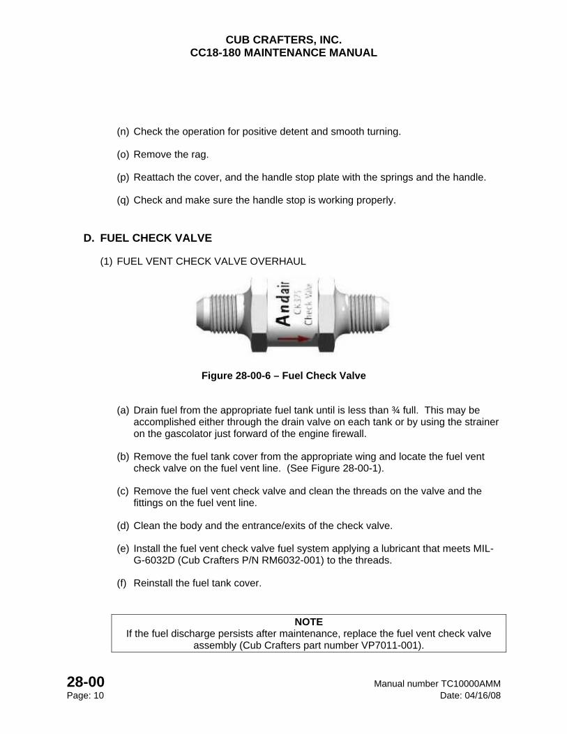
CUB CRAFTERS, INC. CC18-180 MAINTENANCE MANUAL
28-00 Manual number TC10000AMM Page: 10 Date: 04/16/08
(n) Check the operation for positive detent and smooth turning.
(o) Remove the rag.
(p) Reattach the cover, and the handle stop plate with the springs and the handle.
(q) Check and make sure the handle stop is working properly.
D. FUEL CHECK VALVE
(1) FUEL VENT CHECK VALVE OVERHAUL
Figure 28-00-6 – Fuel Check Valve
(a) Drain fuel from the appropriate fuel tank until is less than ¾ full. This may be accomplished either through the drain valve on each tank or by using the strainer on the gascolator just forward of the engine firewall.
(b) Remove the fuel tank cover from the appropriate wing and locate the fuel vent check valve on the fuel vent line. (See Figure 28-00-1).
(c) Remove the fuel vent check valve and clean the threads on the valve and the fittings on the fuel vent line.
(d) Clean the body and the entrance/exits of the check valve.
(e) Install the fuel vent check valve fuel system applying a lubricant that meets MIL-G-6032D (Cub Crafters P/N RM6032-001) to the threads.
(f) Reinstall the fuel tank cover.
NOTE If the fuel discharge persists after maintenance, replace the fuel vent check valve
assembly (Cub Crafters part number VP7011-001).
CHAPTER
32
LANDING GEAR

CUB CRAFTERS, INC. CC18-180 MAINTENANCE MANUAL
Manual number TC10000AMM 32 Date: 11/15/05 Page: i
32 LANDING GEAR 32-00 .................................................................................................................... LANDING GEAR
32-10 .......................................................................................................... MAIN LANDING GEAR
32-20 ........................................................................................................... TAIL LANDING GEAR
32-41 ...................................................................................................................... MAIN WHEELS
32-42 ................................................................................................................................ BRAKES
32-60 ......................................................................................................... AMPHIBIOUS FLOATS
CUB CRAFTERS, INC. CC18-180 MAINTENANCE MANUAL
32 Manual number TC10000AMM
Page: ii Date: 04/17/08
INTENTIONALLY LEFT BLANK
CUB CRAFTERS, INC. CC18-180 MAINTENANCE MANUAL
Manual number TC10000AMM 32-00 Date: 04/17/08 Page: 1
32-00 LANDING GEAR TABLE OF CONTENTS 1. GENERAL .............................................................................................................................. 2
2. TROUBLESHOOTING ........................................................................................................... 2
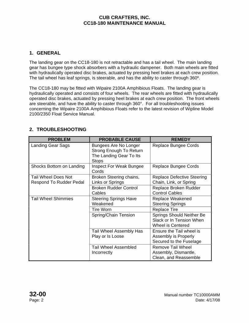
CUB CRAFTERS, INC. CC18-180 MAINTENANCE MANUAL
32-00 Manual number TC10000AMM Page: 2 Date: 4/17/08
1. GENERAL
The landing gear on the CC18-180 is not retractable and has a tail wheel. The main landing gear has bungee type shock absorbers with a hydraulic dampener. Both main wheels are fitted with hydraulically operated disc brakes, actuated by pressing heel brakes at each crew position. The tail wheel has leaf springs, is steerable, and has the ability to caster through 360º. The CC18-180 may be fitted with Wipaire 2100A Amphibious Floats. The landing gear is hydraulically operated and consists of four wheels. The rear wheels are fitted with hydraulically operated disc brakes, actuated by pressing heel brakes at each crew position. The front wheels are steerable, and have the ability to caster through 360°. For all troubleshooting issues concerning the Wipaire 2100A Amphibious Floats refer to the latest revision of Wipline Model 2100/2350 Float Service Manual.
2. TROUBLESHOOTING
PROBLEM PROBABLE CAUSE REMEDY Landing Gear Sags Bungees Are No Longer
Strong Enough To Return The Landing Gear To Its Stops
Replace Bungee Cords
Shocks Bottom on Landing Inspect For Weak Bungee Cords
Replace Bungee Cords
Tail Wheel Does Not Respond To Rudder Pedal
Broken Steering chains, Links or Springs
Replace Defective Steering Chain, Link, or Spring
Broken Rudder Control Cables
Replace Broken Rudder Control Cables
Tail Wheel Shimmies
Steering Springs Have Weakened
Replace Weakened Steering Springs
Tire Worn Replace Tire Spring/Chain Tension Springs Should Neither Be
Slack or In Tension When Wheel is Centered
Tail Wheel Assembly Has Play or Is Loose
Ensure the Tail wheel is Assembly is Properly Secured to the Fuselage
Tail Wheel Assembled Incorrectly
Remove Tail Wheel Assembly, Dismantle, Clean, and Reassemble
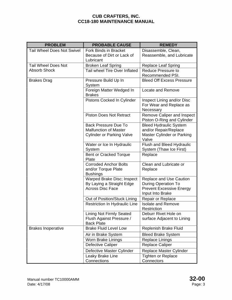
CUB CRAFTERS, INC. CC18-180 MAINTENANCE MANUAL
Manual number TC10000AMM 32-00 Date: 4/17/08 Page: 3
PROBLEM PROBABLE CAUSE REMEDY Tail Wheel Does Not Swivel Fork Binds in Bracket
Because of Dirt or Lack of Lubricant
Disassemble, Clean, Reassemble, and Lubricate
Tail Wheel Does Not Absorb Shock
Broken Leaf Spring Replace Leaf Spring Tail wheel Tire Over Inflated Reduce Pressure to
Recommended PSI. Brakes Drag
Pressure Build Up In System
Bleed Off Excess Pressure
Foreign Matter Wedged In Brakes
Locate and Remove
Pistons Cocked In Cylinder Inspect Lining and/or Disc For Wear and Replace as Necessary
Piston Does Not Retract Remove Caliper and Inspect Piston O-Ring and Cylinder
Back Pressure Due To Malfunction of Master Cylinder or Parking Valve
Bleed Hydraulic System and/or Repair/Replace Master Cylinder or Parking Valve
Water or Ice In Hydraulic System
Flush and Bleed Hydraulic System (Thaw Ice First)
Bent or Cracked Torque Plate
Replace
Corroded Anchor Bolts and/or Torque Plate Bushings
Clean and Lubricate or Replace
Warped Brake Disc; Inspect By Laying a Straight Edge Across Disc Face
Replace and Use Caution During Operation To Prevent Excessive Energy Input Into Brake
Out of Position/Stuck Lining Repair or Replace Restriction In Hydraulic Line Isolate and Remove
Restriction Lining Not Firmly Seated Flush Against Pressure / Back Plate
Deburr Rivet Hole on surface Adjacent to Lining
Brakes Inoperative
Brake Fluid Level Low Replenish Brake Fluid
Air in Brake System Bleed Brake System Worn Brake Linings Replace Linings Defective Caliper Replace Caliper
Defective Master Cylinder Replace Master Cylinder Leaky Brake Line Connections
Tighten or Replace Connectors
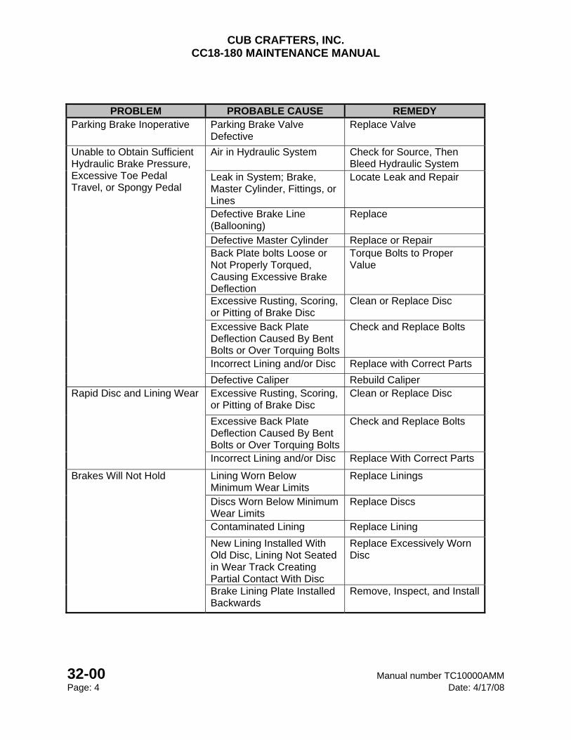
CUB CRAFTERS, INC. CC18-180 MAINTENANCE MANUAL
32-00 Manual number TC10000AMM Page: 4 Date: 4/17/08
PROBLEM PROBABLE CAUSE REMEDY Parking Brake Inoperative Parking Brake Valve
Defective Replace Valve
Unable to Obtain Sufficient Hydraulic Brake Pressure, Excessive Toe Pedal Travel, or Spongy Pedal
Air in Hydraulic System Check for Source, Then Bleed Hydraulic System
Leak in System; Brake, Master Cylinder, Fittings, or Lines
Locate Leak and Repair
Defective Brake Line (Ballooning)
Replace
Defective Master Cylinder Replace or Repair Back Plate bolts Loose or Not Properly Torqued, Causing Excessive Brake Deflection
Torque Bolts to Proper Value
Excessive Rusting, Scoring, or Pitting of Brake Disc
Clean or Replace Disc
Excessive Back Plate Deflection Caused By Bent Bolts or Over Torquing Bolts
Check and Replace Bolts
Incorrect Lining and/or Disc Replace with Correct Parts
Defective Caliper Rebuild Caliper Rapid Disc and Lining Wear Excessive Rusting, Scoring,
or Pitting of Brake Disc Clean or Replace Disc
Excessive Back Plate Deflection Caused By Bent Bolts or Over Torquing Bolts
Check and Replace Bolts
Incorrect Lining and/or Disc Replace With Correct Parts
Brakes Will Not Hold
Lining Worn Below Minimum Wear Limits
Replace Linings
Discs Worn Below Minimum Wear Limits
Replace Discs
Contaminated Lining Replace Lining
New Lining Installed With Old Disc, Lining Not Seated in Wear Track Creating Partial Contact With Disc
Replace Excessively Worn Disc
Brake Lining Plate Installed Backwards
Remove, Inspect, and Install
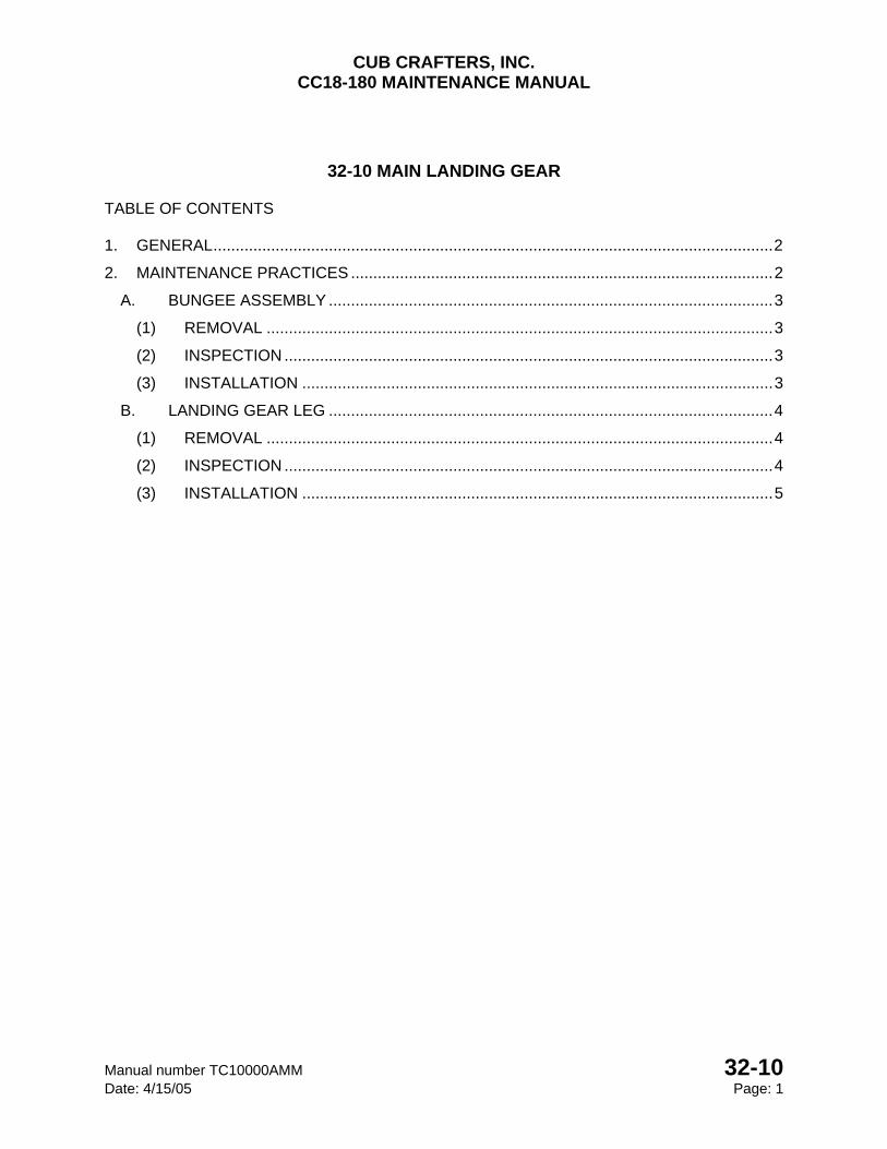
CUB CRAFTERS, INC. CC18-180 MAINTENANCE MANUAL
Manual number TC10000AMM 32-10 Date: 4/15/05 Page: 1
32-10 MAIN LANDING GEAR
TABLE OF CONTENTS
1. GENERAL .............................................................................................................................. 2
2. MAINTENANCE PRACTICES ............................................................................................... 2
A. BUNGEE ASSEMBLY .................................................................................................... 3
(1) REMOVAL .................................................................................................................. 3
(2) INSPECTION .............................................................................................................. 3
(3) INSTALLATION .......................................................................................................... 3
B. LANDING GEAR LEG .................................................................................................... 4
(1) REMOVAL .................................................................................................................. 4
(2) INSPECTION .............................................................................................................. 4
(3) INSTALLATION .......................................................................................................... 5
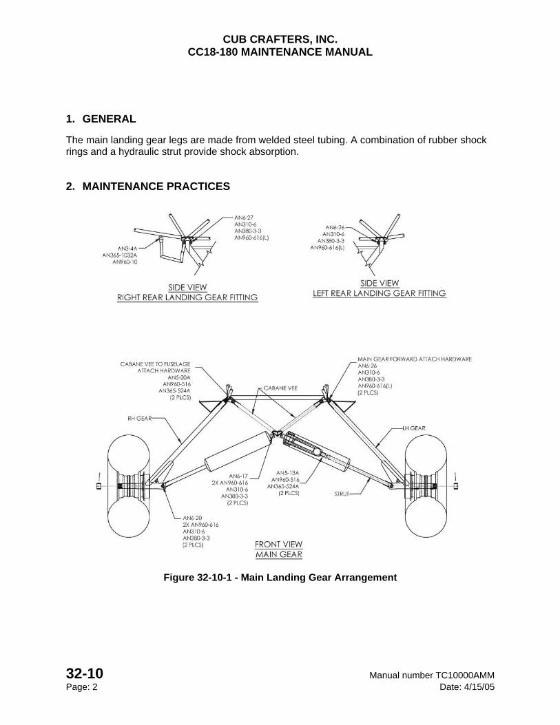
CUB CRAFTERS, INC. CC18-180 MAINTENANCE MANUAL
32-10 Manual number TC10000AMM Page: 2 Date: 4/15/05
1. GENERAL
The main landing gear legs are made from welded steel tubing. A combination of rubber shock rings and a hydraulic strut provide shock absorption.
2. MAINTENANCE PRACTICES
Figure 32-10-1 - Main Landing Gear Arrangement
CUB CRAFTERS, INC. CC18-180 MAINTENANCE MANUAL
Manual number TC10000AMM 32-10 Date: 4/15/05 Page: 3
A. BUNGEE ASSEMBLY
(1) REMOVAL
(a) Chock the main wheel on the opposite side of the landing gear that is to be worked on. Chock the tail wheel. It is not recommended to carry this work out in windy conditions.
(b) Remove the top bungee cover screws and slide the cover down until the lower bungee bolt is exposed (the bungee cords can be inspected at this point and if replacement is required accomplish the following steps).
(c) Jack the aircraft by lifting the wing that is on the same side as the landing gear that is to be worked on. The jack is placed at the forward wing strut to spar attachment point on the desired side. (See 07-00).
(d) Remove the upper shock assembly attach bolt and lower the shock assembly.
(e) Remove the bungee cover end from the shock assembly.
(f) Remove the lower attach bolt and pull the shock out of the strut.
(2) INSPECTION
(a) Check the bungee cords for broken bands, threads, and signs of weakness. Inspect the hydraulic strut for leaking fluid or damage.
NOTE The bungees are replaced every 5 years (See 05-10).
(b) If the cords need replacement, cut the old cords off. Inspect the hydraulic shock for damage and smoothness of operation.
(c) Install new bungee cords using the special tool available from Cub Crafters.
(d) Replace any hardware that is excessively corroded or worn.
(3) INSTALLATION
(a) Insert the shock assembly in the strut. Insert a bolt with a washer through the shock and strut and place a washer and nut on the end of the bolt. Torque the nut to 160-200 in/lbs.
CUB CRAFTERS, INC. CC18-180 MAINTENANCE MANUAL
32-10 Manual number TC10000AMM Page: 4 Date: 4/15/05
(b) Place the bungee cover end over the top shaft of the shock assembly. Align with the top shock hole and the holes in the cabane vee and insert bolt.
(c) Place the washer and the nut on the end of the bolt. Torque to 130 in/lbs. If necessary, tightened past this torque value to align the nut with the nearest hole in the bolt. Safety the nut with a new cotter pin.
(d) Verify that all hardware is installed properly then lower the aircraft back to the ground.
B. LANDING GEAR LEG
(1) REMOVAL
(a) Chock the main wheel on the opposite side of the landing gear that is to be worked on. Chock the tail wheel. It is recommended to carry this work in a sheltered hangar.
(b) Disconnect the brake line from the fuselage.
(c) Jack the aircraft by lifting the wing that is on the same side as the landing gear that is to be removed. The jack is placed at the forward wing strut to spar attachment point on the desired side. (See 07-00).
(d) Remove the lower shock strut attach bolt.
(e) Remove both upper landing gear bolts.
(2) INSPECTION
(a) Inspect the landing gear and fuselage attachment points for cracks, damage, and oversized holes.
(b) Replace or repair affected parts.
(c) Inspect the brake backing plates for cracks or excessive wear.
CUB CRAFTERS, INC. CC18-180 MAINTENANCE MANUAL
Manual number TC10000AMM 32-10 Date: 4/15/05 Page: 5
(3) INSTALLATION
(a) Replace any hardware that is excessively corroded or worn.
(b) Align the upper landing gear attachment holes with the corresponding ones in the fuselage.
(c) If there is a gap between a landing gear leg and the corresponding fuselage ear, fill the gap with washers of the appropriate thickness.
(d) Apply grease to slow corrosion and insert the upper landing gear bolts.
(e) The rear bolt on the right landing gear is longer than the one on the left because the ear of the passenger step must be placed over the bolt end.
(f) Place washers and nuts on the end of the bolts.
(g) Align the hole at the bottom of the shock strut with the holes in the landing gear.
(h) Apply grease to slow corrosion and insert the bolt with a washer under the head. Place washer and nut on the end of the bolt.
(i) Torque all nuts to 130 in/lbs or if necessary, past this value so that the nuts may be aligned with the nearest hole on the corresponding bolt.
(j) Safety the nuts with new cotter pins.
(k) Verify that all the hardware is installed properly and lower the aircraft to the ground.
(l) Reconnect the brake lines and tighten the fittings.
(m) Service the brakes, if needed, to obtain the proper pedal travel. (See 32-42)

CUB CRAFTERS, INC. CC18-180 MAINTENANCE MANUAL
32-10 Manual number TC10000AMM Page: 6 Date: 4/15/05
INTENTIONALLY LEFT BLANK

CUB CRAFTERS, INC. CC18-180 MAINTENANCE MANUAL
Manual number TC10000AMM 32-20 Date: 04/17/08 Page: 1
32-20 TAIL LANDING GEAR TABLE OF CONTENTS 1. GENERAL .............................................................................................................................. 2
2. MAINTENANCE PRACTICES ............................................................................................... 2
A. TAIL LANDING GEAR .................................................................................................... 2
(1) REMOVAL OF TAIL WHEEL AND LEAF SPRINGS .................................................. 2
(2) DISASSEMBLY OF TAIL WHEEL BRACKET AND FORK ......................................... 4
(3) CLEANING .................................................................................................................. 5
(4) INSPECTION OF TAIL WHEEL COMPONENTS ....................................................... 5
(5) MINOR REPAIRS OF TAIL WHEEL COMPONENTS ................................................ 5
(6) REPLACEMENT OF PARTS. ..................................................................................... 5
(7) REASSEMBLY OF TAIL WHEEL BRACKET AND FORK .......................................... 6
(8) INSTALLATION OF TAIL WHEEL AND LEAF SPRINGS .......................................... 7
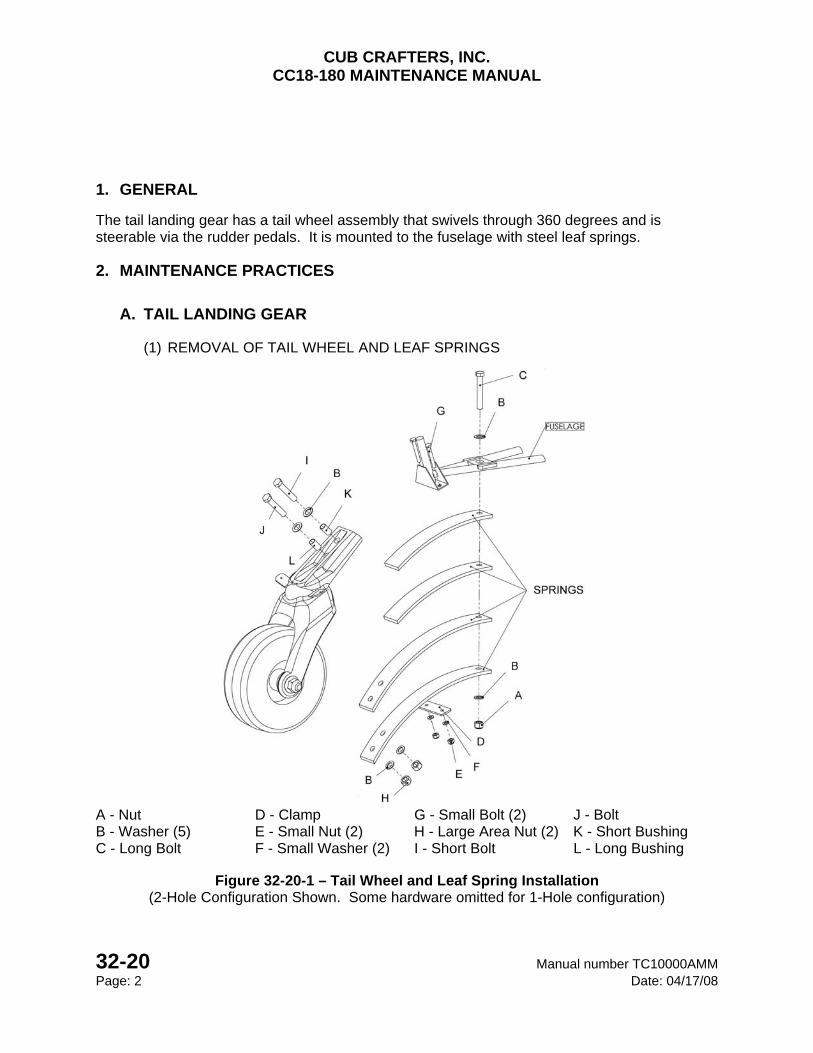
CUB CRAFTERS, INC. CC18-180 MAINTENANCE MANUAL
32-20 Manual number TC10000AMM Page: 2 Date: 04/17/08
1. GENERAL
The tail landing gear has a tail wheel assembly that swivels through 360 degrees and is steerable via the rudder pedals. It is mounted to the fuselage with steel leaf springs.
2. MAINTENANCE PRACTICES
A. TAIL LANDING GEAR
(1) REMOVAL OF TAIL WHEEL AND LEAF SPRINGS
A - Nut D - Clamp G - Small Bolt (2) J - Bolt B - Washer (5) E - Small Nut (2) H - Large Area Nut (2) K - Short Bushing C - Long Bolt F - Small Washer (2) I - Short Bolt L - Long Bushing
Figure 32-20-1 – Tail Wheel and Leaf Spring Installation
(2-Hole Configuration Shown. Some hardware omitted for 1-Hole configuration)
CUB CRAFTERS, INC. CC18-180 MAINTENANCE MANUAL
Manual number TC10000AMM 32-20 Date: 04/17/08 Page: 3
(a) Lift the tail section of the airplane and rest the fuselage on a bench so the tail landing gear clears the ground.
(b) Disconnect the chain links from the tail wheel arms.
(c) Remove the front tail spring attach nut (A) and washer (B).
(d) Disconnect the tail spring clamp (D) by removing the nuts (E), washers (F) and bolts (G).
(e) To separate the springs from the tail wheel, remove the large area nuts (H), washers (B), and bolts (I & J).
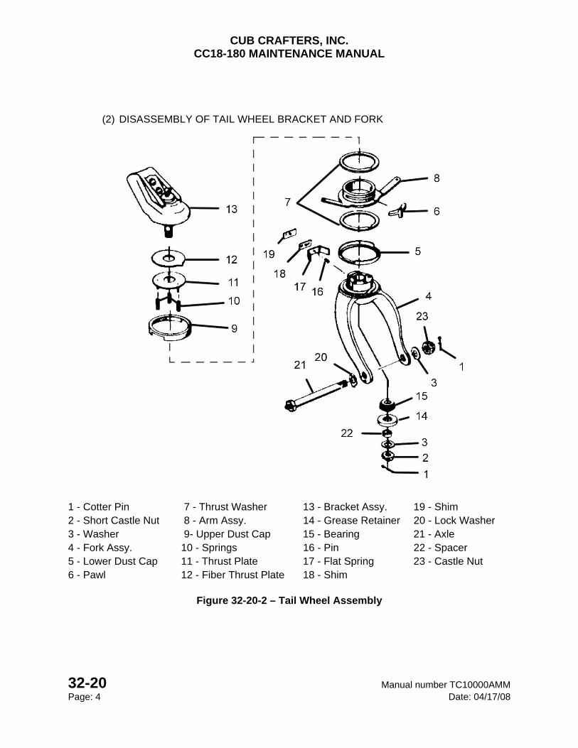
CUB CRAFTERS, INC. CC18-180 MAINTENANCE MANUAL
32-20 Manual number TC10000AMM Page: 4 Date: 04/17/08
(2) DISASSEMBLY OF TAIL WHEEL BRACKET AND FORK
1 - Cotter Pin 7 - Thrust Washer 13 - Bracket Assy. 19 - Shim 2 - Short Castle Nut 8 - Arm Assy. 14 - Grease Retainer 20 - Lock Washer 3 - Washer 9- Upper Dust Cap 15 - Bearing 21 - Axle 4 - Fork Assy. 10 - Springs 16 - Pin 22 - Spacer 5 - Lower Dust Cap 11 - Thrust Plate 17 - Flat Spring 23 - Castle Nut 6 - Pawl 12 - Fiber Thrust Plate 18 - Shim
Figure 32-20-2 – Tail Wheel Assembly

CUB CRAFTERS, INC. CC18-180 MAINTENANCE MANUAL
Manual number TC10000AMM 32-20 Date: 04/17/08 Page: 5
(a) Remove the tire assembly from the fork by removing the cotter pin (1), castle nut (23), and washer (3) then sliding the axle (21) out.
(b) At the bottom of the fork (4) remove the cotter pin (1), short castle nut (2), and washer (3). Carefully pull the fork (11) off of the bracket (1).
(c) Separate the spacer (22), grease retainer (14), and the bearing (15) from the fork (4).
(d) Disengage the lower dust cap (5), thrust washer (7), arm assembly (8), thrust washer (7), pawl (6), upper dust cap (9), springs (10), thrust plate (11), and fiber thrust plate (12) from the fork (4) and bracket (13).
(3) CLEANING
(a) Clean all metal parts (including the bearings) in a cleaning solution. Dry all parts with compressed air.
(4) INSPECTION OF TAIL WHEEL COMPONENTS
(See Figure 32-20-1 and Figure 32-20-2)
(a) Check the leaf springs for damage or twisting (Figure 32-20-1)
(b) Replace if condition dictates.
(c) Inspect the arm assembly (8, Figure 32-20-2), flat spring (17, Figure 32-20-2), fork (4, Figure 32-20-2), and bracket (13, Figure 32-20-2) for excessive wear, cracks or other damage. Replace damaged parts.
(d) Examine the thrust washers (7, Figure 32-20-2) for wear, scoring, or other damage. Replace if necessary.
(e) Inspect the bearing (15, Figure 32-20-2) and races for wear or damage. Replace if necessary.
(5) MINOR REPAIRS OF TAIL WHEEL COMPONENTS
(See Figure 32-20-2)
(a) The components that make up the tailwheel assembly may not be repaired except that minor realignments are permitted, such as minor dents and bends.
(6) REPLACEMENT OF PARTS.
(a) Replace all cotter pins that have been removed with new cotter pins.

CUB CRAFTERS, INC. CC18-180 MAINTENANCE MANUAL
32-20 Manual number TC10000AMM Page: 6 Date: 04/17/08
(7) REASSEMBLY OF TAIL WHEEL BRACKET AND FORK
(See Figure 32-20-2)
(a) Hand apply grease to all internal parts and pack the bearing (15) with grease (MIL-G-81322E).
(b) Place the lower dust cap (5) on the fork (4) and the thrust washer (7) on the fork (4) being sure to align the notch with the locking pin in the fork (4).
(c) Position the pawl (6) on the arm (8) with the longest lobe down and place the arm assembly (8) on the fork (4).
(d) Position the other thrust washer (7) and the upper dust cap (9) on the arm assembly (8).
(e) Insert 3 springs (10) in the proper holes on the top of the fork (4) so the thrust plate (11) can be placed on top.
(f) Position the fiber thrust plate (12) in the bracket (13) so the nub is aligned with the groove and insert the bracket assembly (13) into the fork (4) maintaining the alignment of all the interlocking parts.
(g) Place the bearing (15), grease retainer (14), spacer (22), and washer (3) in the fork (4). Exert pressure on the bracket (13) to engage the short castle nut (2) with the bracket assembly post.
(h) Tighten the nut (2) securely, back off to the first cotter pin hole in the bracket post, and secure with a cotter pin (1). These last steps may be accomplished once the tail wheel assembly is installed back on the fuselage.
(i) Check to verify proper tailwheel pivoting and tension.
(j) Install the tire assembly on the fork by sliding the axle (21) with the lock washer (20) through the fork and tire assembly.
(k) Secure with a washer (3) and castle nut (23). Tighten the nut until there is no free play in the bearings and there is a slight amount of friction. Safety with a cotter pin (1).
(l) Pump the tail wheel bracket assembly (13) and axle (21) full of grease (MIL-G-81322E) then wipe off the excess.
CUB CRAFTERS, INC. CC18-180 MAINTENANCE MANUAL
Manual number TC10000AMM 32-20 Date: 04/17/08 Page: 7
(8) INSTALLATION OF TAIL WHEEL AND LEAF SPRINGS
(See Figure 32-20-1)
(a) Position the tail wheel springs on the fuselage with long bolt (C) and hold in place with a washer (B) and a nut (A).
(b) Install the small bolts (G), clamp (D), and small washers (F) with the small nuts (E) only finger tight.
(c) Insert the bushings (K, L) into the tail wheel assembly, if they were removed.
(d) Insert the bolts (I, J) through the bushings and tail wheel assembly.
(e) Hold in place with two washers (B) and two large area nuts (H).
(f) Tighten the large area nuts (H) to 270-300 in/lbs.
(g) Tighten the nut (A) to 270-300 in/lbs.
(h) Tighten the small nuts (E) to 70-100 in/lbs.
(i) Reconnect the chain links to the tail wheel arms. The springs and chains should neither be slack nor have tension when the wheel is centered. It may be necessary to adjust the number of chain links to achieve this.
(j) Lower the tail section to the ground.

CUB CRAFTERS, INC. CC18-180 MAINTENANCE MANUAL
32-20 Manual number TC10000AMM Page: 8 Date: 04/17/08
INTENTIONALLY LEFT BLANK
CUB CRAFTERS, INC. CC18-180 MAINTENANCE MANUAL
Manual number TC10000AMM 32-41 Date: 4/15/05 Page: 1
32-41 MAIN WHEELS AND TIRES
TABLE OF CONTENTS 1. GENERAL .............................................................................................................................. 2
2. MAINTENANCE PRACTICES ............................................................................................... 2
A. MAIN WHEELS .............................................................................................................. 2
(1) REMOVAL ...................................................................................................................... 2
(2) WHEEL DISASSEMBLY ................................................................................................ 3
(3) INSPECTION ................................................................................................................. 5
(4) WHEEL ASSEMBLY ...................................................................................................... 6
B. TAIL WHEEL .................................................................................................................. 7
(1) DISASSEMBLY .............................................................................................................. 8
(2) INSPECTION ................................................................................................................. 8
(3) REASSEMBLY OF TAIL WHEEL. .................................................................................. 8

CUB CRAFTERS, INC. CC18-180 MAINTENANCE MANUAL
32-41 Manual number TC10000AMM Page: 2 Date: 4/17/08
1. GENERAL
The main wheels are of aluminum construction and are designed to be used with tires and tubes. The standard CC18-180 is equipped with 8.50 X 6-6 tires. Larger tires are offered as optional equipment.
2. MAINTENANCE PRACTICES
A. MAIN WHEELS
(1) REMOVAL
(a) Chock the main wheel on the opposite side of the landing gear that is to be worked on. Chock the tail wheel. It is not recommended to carry this work out in windy conditions.
(b) Remove the hubcap and the axle nut cotter pin.
(c) Cut the safety wire and remove the brake back plate bolts.
(d) Place a jack under the axle and raise the tire off the ground (See Chapter 07-00).
(e) Remove the axle nut and wheel.
(f) The bearings can be removed, cleaned and inspected without disassembling the wheel and removing the tire.
CUB CRAFTERS, INC. CC18-180 MAINTENANCE MANUAL
Manual number TC10000AMM 32-41 Date: 4/15/05 Page: 3
(2) WHEEL DISASSEMBLY
See Figure 32-41-1
CAUTION Care must be taken to avoid damaging wheel halves when breaking tire beads loose.
WARNING DO NOT ATTEMPT TO REMOVE VALVE CORE UNTIL TIRE HAS BEEN COMPLETELY
DEFLATED. THE VALVE CORE WILL BE EJECTED AT A HIGH VELOCITY IF IT IS UNSCREWED BEFORE THE AIR PRESSURE HAS BEEN RELEASED.
WARNING INJURY CAN RESULT WHEN ATTEMPTING TO SEPARATE WHEEL HALVES WITH THE
TUBE INFLATED.
(a) Deflate the tire.
(b) Break the tire bead loose from the wheel.
(c) Remove the wheel halve nuts (6) and washers (5).
(d) Pull the wheel halves (1, 3) apart being careful with the tubes valve stem.
(e) Remove the snap ring (11), grease seals (8, 9) and bearing (2). Repeat on other wheel half.

CUB CRAFTERS, INC. CC18-180 MAINTENANCE MANUAL
32-41 Manual number TC10000AMM Page: 4 Date: 4/17/08
1 - Inner Wheel Half 4 - Bolt (6) 7 - Tire 10 - Tube 2 - Bearing 5 - Washer (12) 8 -Grease Seal Ring (4) 11 - Snap Ring 3 - Outer Wheel Half 6 - Nut (12) 9 -Grease Seal Felt (2) 12 - Brake Disc
Figure 32-41-1 – Wheel

CUB CRAFTERS, INC. CC18-180 MAINTENANCE MANUAL
Manual number TC10000AMM 32-41 Date: 4/15/05 Page: 5
(3) INSPECTION
(f) Axle
Visually inspect the axle to make sure there are no cracks or grooves.
(g) Tire and Tube
Visually inspect the tires inside and outside for cuts, uneven or excessive wear, and penetration by foreign objects.
Visually inspect the inner tube for wear, cuts or cracks. Pay close attention to the valve stem base.
The tire should be removed when the tread is worn to the base of a groove. Tires with wear through the top fabric layer can only remain in service long enough to return to a maintenance base to be replaced.
(h) Wheel Halves
Inspect the wheel halves for cracks or corrosion.
(i) Discs
Inspect the brake disc attachment points for cracking or distortion.
Minimum disc thickness is 0.220 in.
(j) Bearings
Clean all metal parts (including the bearings) in a cleaning solution. Dry all parts with compressed air.
Inspect the bearing and races for wear or damage. Replace if necessary.
(k) Replace unserviceable parts as required.
CUB CRAFTERS, INC. CC18-180 MAINTENANCE MANUAL
32-41 Manual number TC10000AMM Page: 6 Date: 4/17/08
(4) WHEEL ASSEMBLY
(l) If a new tire or tube is used or the old one is sticky, dust the inside of the tire lightly with talcum powder.
(m) Inflate the tube, inside the tire, with enough air to start to fill it out so it will not be pinched between the wheel halves.
(n) Insert the outboard wheel half (1) over the valve stem and into the tire.
(o) Mount the inner wheel half (1) onto the outer wheel half (3).
(p) Secure the brake disc (12) using six bolts (4) with a washer (5) under each head.
(q) Place a washer (5) and nut (6) on each bolt (4) and torque to 85-95 in/lbs.
(r) Inflate the tires per recommended pressure (Reference Chapter 12-00).
(s) Allow time for the air trapped between the tube and tire to escape and recheck the pressure.
(t) Pack the bearings with grease (MIL-G-81322E).
(u) Insert the bearing (4), inner grease seal ring (8), grease seal felt (9), outer grease seal ring (8) and secure with a snap ring (11). Repeat on the opposite side.
(5) MAIN WHEEL INSTALLATION
(a) Place the wheel on axle and tighten the axle nut so the tire will turn 1 ½ -2 times after a good spin.
(b) Safety with a cotter pin.
(c) Verify the tire pressure. Reference Chapter 12-00.
(d) Safety the axle nut with a cotter pin. Verify before attaching the hubcaps.
(e) Position the brake back plates, insert the bolts, and torque to 65-75 in/lbs.
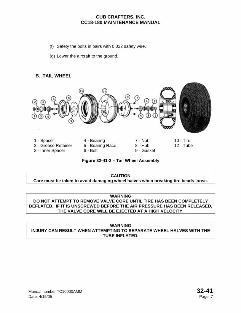
CUB CRAFTERS, INC. CC18-180 MAINTENANCE MANUAL
Manual number TC10000AMM 32-41 Date: 4/15/05 Page: 7
(f) Safety the bolts in pairs with 0.032 safety wire.
(g) Lower the aircraft to the ground.
B. TAIL WHEEL
1 - Spacer 4 - Bearing 7 - Nut 10 - Tire 2 - Grease Retainer 5 - Bearing Race 8 - Hub 12 - Tube 3 - Inner Spacer 6 - Bolt 9 - Gasket
Figure 32-41-2 – Tail Wheel Assembly
CAUTION Care must be taken to avoid damaging wheel halves when breaking tire beads loose.
WARNING DO NOT ATTEMPT TO REMOVE VALVE CORE UNTIL TIRE HAS BEEN COMPLETELY
DEFLATED. IF IT IS UNSCREWED BEFORE THE AIR PRESSURE HAS BEEN RELEASED, THE VALVE CORE WILL BE EJECTED AT A HIGH VELOCITY.
WARNING INJURY CAN RESULT WHEN ATTEMPTING TO SEPARATE WHEEL HALVES WITH THE
TUBE INFLATED.
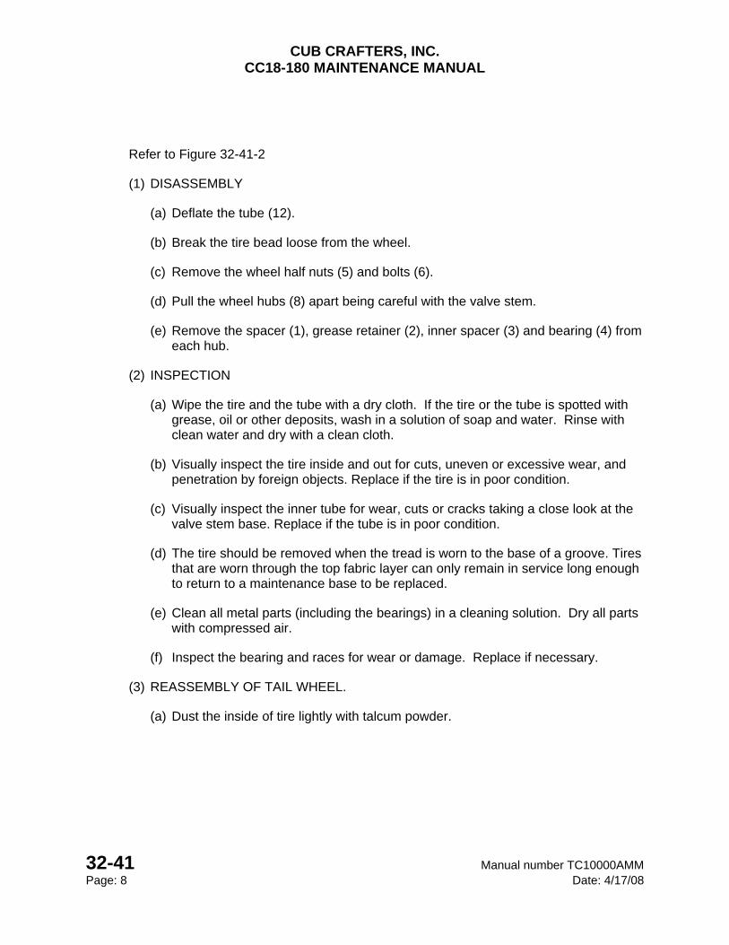
CUB CRAFTERS, INC. CC18-180 MAINTENANCE MANUAL
32-41 Manual number TC10000AMM Page: 8 Date: 4/17/08
Refer to Figure 32-41-2
(1) DISASSEMBLY
(a) Deflate the tube (12).
(b) Break the tire bead loose from the wheel.
(c) Remove the wheel half nuts (5) and bolts (6).
(d) Pull the wheel hubs (8) apart being careful with the valve stem.
(e) Remove the spacer (1), grease retainer (2), inner spacer (3) and bearing (4) from each hub.
(2) INSPECTION
(a) Wipe the tire and the tube with a dry cloth. If the tire or the tube is spotted with grease, oil or other deposits, wash in a solution of soap and water. Rinse with clean water and dry with a clean cloth.
(b) Visually inspect the tire inside and out for cuts, uneven or excessive wear, and penetration by foreign objects. Replace if the tire is in poor condition.
(c) Visually inspect the inner tube for wear, cuts or cracks taking a close look at the valve stem base. Replace if the tube is in poor condition.
(d) The tire should be removed when the tread is worn to the base of a groove. Tires that are worn through the top fabric layer can only remain in service long enough to return to a maintenance base to be replaced.
(e) Clean all metal parts (including the bearings) in a cleaning solution. Dry all parts with compressed air.
(f) Inspect the bearing and races for wear or damage. Replace if necessary.
(3) REASSEMBLY OF TAIL WHEEL.
(a) Dust the inside of tire lightly with talcum powder.

CUB CRAFTERS, INC. CC18-180 MAINTENANCE MANUAL
Manual number TC10000AMM 32-41 Date: 4/15/05 Page: 9
(b) Place the tube (12) in the tire (10).
(c) Insert the wheel hubs (8) with the gasket (9) in between into the tire and tube assembly. Make certain the gasket (9) is properly aligned with tube valve and hub bolt holes.
(d) Insert 4 bolts and engage with 4 nuts. Torque to 80-100 in/lbs.
(e) Inflate the tire to 38 pounds.
(f) Pack the bearings with grease (MIL-G-81322E).
(g) Insert a bearing (4), inner spacer (3), grease retainer (2) and spacer (1) into the each wheel hub.
(h) To install on the airplane see Chapter 32-20 2.A.(7)(J).
CUB CRAFTERS, INC. CC18-180 MAINTENANCE MANUAL
32-41 Manual number TC10000AMM Page: 10 Date: 4/17/08
INTENTIONALLY LEFT BLANK
CUB CRAFTERS, INC. CC18-180 MAINTENANCE MANUAL
Manual number TC10000AMM 32-20 Date: 04/17/08 Page: 1
32-20 TAIL LANDING GEAR TABLE OF CONTENTS 1. GENERAL .............................................................................................................................. 2
2. MAINTENANCE PRACTICES ............................................................................................... 2
A. TAIL LANDING GEAR .................................................................................................... 2
(1) REMOVAL OF TAIL WHEEL AND LEAF SPRINGS .................................................. 2
(2) DISASSEMBLY OF TAIL WHEEL BRACKET AND FORK ......................................... 4
(3) CLEANING .................................................................................................................. 5
(4) INSPECTION OF TAIL WHEEL COMPONENTS ....................................................... 5
(5) MINOR REPAIRS OF TAIL WHEEL COMPONENTS ................................................ 5
(6) REPLACEMENT OF PARTS. ..................................................................................... 5
(7) REASSEMBLY OF TAIL WHEEL BRACKET AND FORK .......................................... 6
(8) INSTALLATION OF TAIL WHEEL AND LEAF SPRINGS .......................................... 7

CUB CRAFTERS, INC. CC18-180 MAINTENANCE MANUAL
32-20 Manual number TC10000AMM Page: 2 Date: 04/17/08
1. GENERAL
The tail landing gear has a tail wheel assembly that swivels through 360 degrees and is steerable via the rudder pedals. It is mounted to the fuselage with steel leaf springs.
2. MAINTENANCE PRACTICES
A. TAIL LANDING GEAR
(1) REMOVAL OF TAIL WHEEL AND LEAF SPRINGS
A - Nut D - Clamp G - Small Bolt (2) J - Bolt B - Washer (5) E - Small Nut (2) H - Large Area Nut (2) K - Short Bushing C - Long Bolt F - Small Washer (2) I - Short Bolt L - Long Bushing
Figure 32-20-1 – Tail Wheel and Leaf Spring Installation
(2-Hole Configuration Shown. Some hardware omitted for 1-Hole configuration)

CUB CRAFTERS, INC. CC18-180 MAINTENANCE MANUAL
Manual number TC10000AMM 32-20 Date: 04/17/08 Page: 3
(a) Lift the tail section of the airplane and rest the fuselage on a bench so the tail landing gear clears the ground.
(b) Disconnect the chain links from the tail wheel arms.
(c) Remove the front tail spring attach nut (A) and washer (B).
(d) Disconnect the tail spring clamp (D) by removing the nuts (E), washers (F) and bolts (G).
(e) To separate the springs from the tail wheel, remove the large area nuts (H), washers (B), and bolts (I & J).

CUB CRAFTERS, INC. CC18-180 MAINTENANCE MANUAL
32-20 Manual number TC10000AMM Page: 4 Date: 04/17/08
(2) DISASSEMBLY OF TAIL WHEEL BRACKET AND FORK
1 - Cotter Pin 7 - Thrust Washer 13 - Bracket Assy. 19 - Shim 2 - Short Castle Nut 8 - Arm Assy. 14 - Grease Retainer 20 - Lock Washer 3 - Washer 9- Upper Dust Cap 15 - Bearing 21 - Axle 4 - Fork Assy. 10 - Springs 16 - Pin 22 - Spacer 5 - Lower Dust Cap 11 - Thrust Plate 17 - Flat Spring 23 - Castle Nut 6 - Pawl 12 - Fiber Thrust Plate 18 - Shim
Figure 32-20-2 – Tail Wheel Assembly
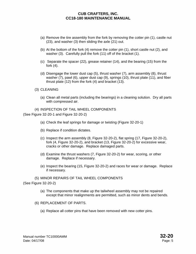
CUB CRAFTERS, INC. CC18-180 MAINTENANCE MANUAL
Manual number TC10000AMM 32-20 Date: 04/17/08 Page: 5
(a) Remove the tire assembly from the fork by removing the cotter pin (1), castle nut (23), and washer (3) then sliding the axle (21) out.
(b) At the bottom of the fork (4) remove the cotter pin (1), short castle nut (2), and washer (3). Carefully pull the fork (11) off of the bracket (1).
(c) Separate the spacer (22), grease retainer (14), and the bearing (15) from the fork (4).
(d) Disengage the lower dust cap (5), thrust washer (7), arm assembly (8), thrust washer (7), pawl (6), upper dust cap (9), springs (10), thrust plate (11), and fiber thrust plate (12) from the fork (4) and bracket (13).
(3) CLEANING
(a) Clean all metal parts (including the bearings) in a cleaning solution. Dry all parts with compressed air.
(4) INSPECTION OF TAIL WHEEL COMPONENTS
(See Figure 32-20-1 and Figure 32-20-2)
(a) Check the leaf springs for damage or twisting (Figure 32-20-1)
(b) Replace if condition dictates.
(c) Inspect the arm assembly (8, Figure 32-20-2), flat spring (17, Figure 32-20-2), fork (4, Figure 32-20-2), and bracket (13, Figure 32-20-2) for excessive wear, cracks or other damage. Replace damaged parts.
(d) Examine the thrust washers (7, Figure 32-20-2) for wear, scoring, or other damage. Replace if necessary.
(e) Inspect the bearing (15, Figure 32-20-2) and races for wear or damage. Replace if necessary.
(5) MINOR REPAIRS OF TAIL WHEEL COMPONENTS
(See Figure 32-20-2)
(a) The components that make up the tailwheel assembly may not be repaired except that minor realignments are permitted, such as minor dents and bends.
(6) REPLACEMENT OF PARTS.
(a) Replace all cotter pins that have been removed with new cotter pins.
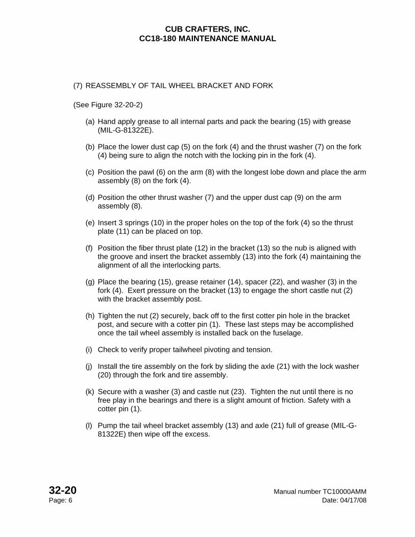
CUB CRAFTERS, INC. CC18-180 MAINTENANCE MANUAL
32-20 Manual number TC10000AMM Page: 6 Date: 04/17/08
(7) REASSEMBLY OF TAIL WHEEL BRACKET AND FORK
(See Figure 32-20-2)
(a) Hand apply grease to all internal parts and pack the bearing (15) with grease (MIL-G-81322E).
(b) Place the lower dust cap (5) on the fork (4) and the thrust washer (7) on the fork (4) being sure to align the notch with the locking pin in the fork (4).
(c) Position the pawl (6) on the arm (8) with the longest lobe down and place the arm assembly (8) on the fork (4).
(d) Position the other thrust washer (7) and the upper dust cap (9) on the arm assembly (8).
(e) Insert 3 springs (10) in the proper holes on the top of the fork (4) so the thrust plate (11) can be placed on top.
(f) Position the fiber thrust plate (12) in the bracket (13) so the nub is aligned with the groove and insert the bracket assembly (13) into the fork (4) maintaining the alignment of all the interlocking parts.
(g) Place the bearing (15), grease retainer (14), spacer (22), and washer (3) in the fork (4). Exert pressure on the bracket (13) to engage the short castle nut (2) with the bracket assembly post.
(h) Tighten the nut (2) securely, back off to the first cotter pin hole in the bracket post, and secure with a cotter pin (1). These last steps may be accomplished once the tail wheel assembly is installed back on the fuselage.
(i) Check to verify proper tailwheel pivoting and tension.
(j) Install the tire assembly on the fork by sliding the axle (21) with the lock washer (20) through the fork and tire assembly.
(k) Secure with a washer (3) and castle nut (23). Tighten the nut until there is no free play in the bearings and there is a slight amount of friction. Safety with a cotter pin (1).
(l) Pump the tail wheel bracket assembly (13) and axle (21) full of grease (MIL-G-81322E) then wipe off the excess.

CUB CRAFTERS, INC. CC18-180 MAINTENANCE MANUAL
Manual number TC10000AMM 32-20 Date: 04/17/08 Page: 7
(8) INSTALLATION OF TAIL WHEEL AND LEAF SPRINGS
(See Figure 32-20-1)
(a) Position the tail wheel springs on the fuselage with long bolt (C) and hold in place with a washer (B) and a nut (A).
(b) Install the small bolts (G), clamp (D), and small washers (F) with the small nuts (E) only finger tight.
(c) Insert the bushings (K, L) into the tail wheel assembly, if they were removed.
(d) Insert the bolts (I, J) through the bushings and tail wheel assembly.
(e) Hold in place with two washers (B) and two large area nuts (H).
(f) Tighten the large area nuts (H) to 270-300 in/lbs.
(g) Tighten the nut (A) to 270-300 in/lbs.
(h) Tighten the small nuts (E) to 70-100 in/lbs.
(i) Reconnect the chain links to the tail wheel arms. The springs and chains should neither be slack nor have tension when the wheel is centered. It may be necessary to adjust the number of chain links to achieve this.
(j) Lower the tail section to the ground.

CUB CRAFTERS, INC. CC18-180 MAINTENANCE MANUAL
32-20 Manual number TC10000AMM Page: 8 Date: 04/17/08
INTENTIONALLY LEFT BLANK

CUB CRAFTERS, INC. CC18-180 MAINTENANCE MANUAL
Manual number TC10000AMM 32-41 Date: 4/15/05 Page: 1
32-41 MAIN WHEELS AND TIRES
TABLE OF CONTENTS 1. GENERAL .............................................................................................................................. 2
2. MAINTENANCE PRACTICES ............................................................................................... 2
A. MAIN WHEELS .............................................................................................................. 2
(1) REMOVAL ...................................................................................................................... 2
(2) WHEEL DISASSEMBLY ................................................................................................ 3
(3) INSPECTION ................................................................................................................. 5
(4) WHEEL ASSEMBLY ...................................................................................................... 6
B. TAIL WHEEL .................................................................................................................. 7
(1) DISASSEMBLY .............................................................................................................. 8
(2) INSPECTION ................................................................................................................. 8
(3) REASSEMBLY OF TAIL WHEEL. .................................................................................. 8
CUB CRAFTERS, INC. CC18-180 MAINTENANCE MANUAL
32-41 Manual number TC10000AMM Page: 2 Date: 4/17/08
1. GENERAL
The main wheels are of aluminum construction and are designed to be used with tires and tubes. The standard CC18-180 is equipped with 8.50 X 6-6 tires. Larger tires are offered as optional equipment.
2. MAINTENANCE PRACTICES
A. MAIN WHEELS
(1) REMOVAL
(a) Chock the main wheel on the opposite side of the landing gear that is to be worked on. Chock the tail wheel. It is not recommended to carry this work out in windy conditions.
(b) Remove the hubcap and the axle nut cotter pin.
(c) Cut the safety wire and remove the brake back plate bolts.
(d) Place a jack under the axle and raise the tire off the ground (See Chapter 07-00).
(e) Remove the axle nut and wheel.
(f) The bearings can be removed, cleaned and inspected without disassembling the wheel and removing the tire.

CUB CRAFTERS, INC. CC18-180 MAINTENANCE MANUAL
Manual number TC10000AMM 32-41 Date: 4/15/05 Page: 3
(2) WHEEL DISASSEMBLY
See Figure 32-41-1
CAUTION Care must be taken to avoid damaging wheel halves when breaking tire beads loose.
WARNING DO NOT ATTEMPT TO REMOVE VALVE CORE UNTIL TIRE HAS BEEN COMPLETELY
DEFLATED. THE VALVE CORE WILL BE EJECTED AT A HIGH VELOCITY IF IT IS UNSCREWED BEFORE THE AIR PRESSURE HAS BEEN RELEASED.
WARNING INJURY CAN RESULT WHEN ATTEMPTING TO SEPARATE WHEEL HALVES WITH THE
TUBE INFLATED.
(a) Deflate the tire.
(b) Break the tire bead loose from the wheel.
(c) Remove the wheel halve nuts (6) and washers (5).
(d) Pull the wheel halves (1, 3) apart being careful with the tubes valve stem.
(e) Remove the snap ring (11), grease seals (8, 9) and bearing (2). Repeat on other wheel half.
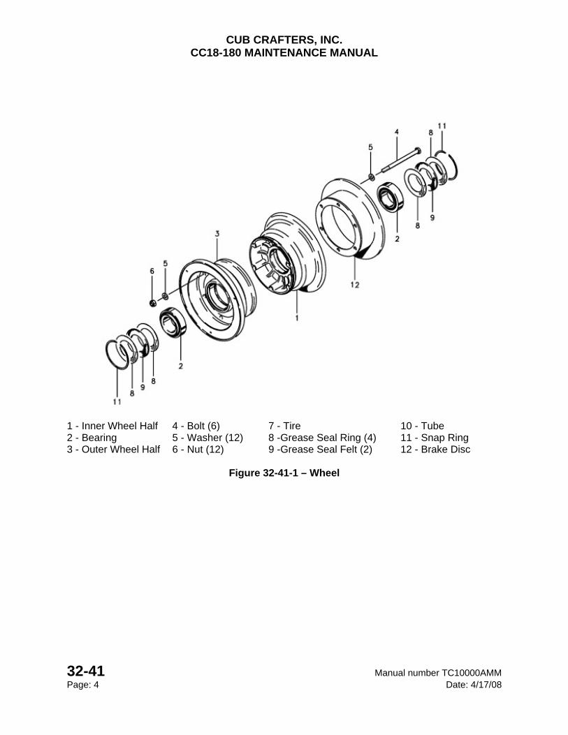
CUB CRAFTERS, INC. CC18-180 MAINTENANCE MANUAL
32-41 Manual number TC10000AMM Page: 4 Date: 4/17/08
1 - Inner Wheel Half 4 - Bolt (6) 7 - Tire 10 - Tube 2 - Bearing 5 - Washer (12) 8 -Grease Seal Ring (4) 11 - Snap Ring 3 - Outer Wheel Half 6 - Nut (12) 9 -Grease Seal Felt (2) 12 - Brake Disc
Figure 32-41-1 – Wheel
CUB CRAFTERS, INC. CC18-180 MAINTENANCE MANUAL
Manual number TC10000AMM 32-41 Date: 4/15/05 Page: 5
(3) INSPECTION
(f) Axle
Visually inspect the axle to make sure there are no cracks or grooves.
(g) Tire and Tube
Visually inspect the tires inside and outside for cuts, uneven or excessive wear, and penetration by foreign objects.
Visually inspect the inner tube for wear, cuts or cracks. Pay close attention to the valve stem base.
The tire should be removed when the tread is worn to the base of a groove. Tires with wear through the top fabric layer can only remain in service long enough to return to a maintenance base to be replaced.
(h) Wheel Halves
Inspect the wheel halves for cracks or corrosion.
(i) Discs
Inspect the brake disc attachment points for cracking or distortion.
Minimum disc thickness is 0.220 in.
(j) Bearings
Clean all metal parts (including the bearings) in a cleaning solution. Dry all parts with compressed air.
Inspect the bearing and races for wear or damage. Replace if necessary.
(k) Replace unserviceable parts as required.

CUB CRAFTERS, INC. CC18-180 MAINTENANCE MANUAL
32-41 Manual number TC10000AMM Page: 6 Date: 4/17/08
(4) WHEEL ASSEMBLY
(l) If a new tire or tube is used or the old one is sticky, dust the inside of the tire lightly with talcum powder.
(m) Inflate the tube, inside the tire, with enough air to start to fill it out so it will not be pinched between the wheel halves.
(n) Insert the outboard wheel half (1) over the valve stem and into the tire.
(o) Mount the inner wheel half (1) onto the outer wheel half (3).
(p) Secure the brake disc (12) using six bolts (4) with a washer (5) under each head.
(q) Place a washer (5) and nut (6) on each bolt (4) and torque to 85-95 in/lbs.
(r) Inflate the tires per recommended pressure (Reference Chapter 12-00).
(s) Allow time for the air trapped between the tube and tire to escape and recheck the pressure.
(t) Pack the bearings with grease (MIL-G-81322E).
(u) Insert the bearing (4), inner grease seal ring (8), grease seal felt (9), outer grease seal ring (8) and secure with a snap ring (11). Repeat on the opposite side.
(5) MAIN WHEEL INSTALLATION
(a) Place the wheel on axle and tighten the axle nut so the tire will turn 1 ½ -2 times after a good spin.
(b) Safety with a cotter pin.
(c) Verify the tire pressure. Reference Chapter 12-00.
(d) Safety the axle nut with a cotter pin. Verify before attaching the hubcaps.
(e) Position the brake back plates, insert the bolts, and torque to 65-75 in/lbs.

CUB CRAFTERS, INC. CC18-180 MAINTENANCE MANUAL
Manual number TC10000AMM 32-41 Date: 4/15/05 Page: 7
(f) Safety the bolts in pairs with 0.032 safety wire.
(g) Lower the aircraft to the ground.
B. TAIL WHEEL
1 - Spacer 4 - Bearing 7 - Nut 10 - Tire 2 - Grease Retainer 5 - Bearing Race 8 - Hub 12 - Tube 3 - Inner Spacer 6 - Bolt 9 - Gasket
Figure 32-41-2 – Tail Wheel Assembly
CAUTION Care must be taken to avoid damaging wheel halves when breaking tire beads loose.
WARNING DO NOT ATTEMPT TO REMOVE VALVE CORE UNTIL TIRE HAS BEEN COMPLETELY
DEFLATED. IF IT IS UNSCREWED BEFORE THE AIR PRESSURE HAS BEEN RELEASED, THE VALVE CORE WILL BE EJECTED AT A HIGH VELOCITY.
WARNING INJURY CAN RESULT WHEN ATTEMPTING TO SEPARATE WHEEL HALVES WITH THE
TUBE INFLATED.

CUB CRAFTERS, INC. CC18-180 MAINTENANCE MANUAL
32-41 Manual number TC10000AMM Page: 8 Date: 4/17/08
Refer to Figure 32-41-2
(1) DISASSEMBLY
(a) Deflate the tube (12).
(b) Break the tire bead loose from the wheel.
(c) Remove the wheel half nuts (5) and bolts (6).
(d) Pull the wheel hubs (8) apart being careful with the valve stem.
(e) Remove the spacer (1), grease retainer (2), inner spacer (3) and bearing (4) from each hub.
(2) INSPECTION
(a) Wipe the tire and the tube with a dry cloth. If the tire or the tube is spotted with grease, oil or other deposits, wash in a solution of soap and water. Rinse with clean water and dry with a clean cloth.
(b) Visually inspect the tire inside and out for cuts, uneven or excessive wear, and penetration by foreign objects. Replace if the tire is in poor condition.
(c) Visually inspect the inner tube for wear, cuts or cracks taking a close look at the valve stem base. Replace if the tube is in poor condition.
(d) The tire should be removed when the tread is worn to the base of a groove. Tires that are worn through the top fabric layer can only remain in service long enough to return to a maintenance base to be replaced.
(e) Clean all metal parts (including the bearings) in a cleaning solution. Dry all parts with compressed air.
(f) Inspect the bearing and races for wear or damage. Replace if necessary.
(3) REASSEMBLY OF TAIL WHEEL.
(a) Dust the inside of tire lightly with talcum powder.
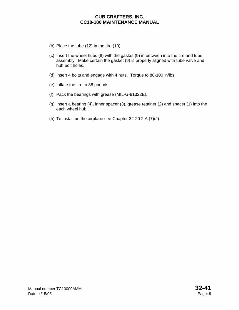
CUB CRAFTERS, INC. CC18-180 MAINTENANCE MANUAL
Manual number TC10000AMM 32-41 Date: 4/15/05 Page: 9
(b) Place the tube (12) in the tire (10).
(c) Insert the wheel hubs (8) with the gasket (9) in between into the tire and tube assembly. Make certain the gasket (9) is properly aligned with tube valve and hub bolt holes.
(d) Insert 4 bolts and engage with 4 nuts. Torque to 80-100 in/lbs.
(e) Inflate the tire to 38 pounds.
(f) Pack the bearings with grease (MIL-G-81322E).
(g) Insert a bearing (4), inner spacer (3), grease retainer (2) and spacer (1) into the each wheel hub.
(h) To install on the airplane see Chapter 32-20 2.A.(7)(J).

CUB CRAFTERS, INC. CC18-180 MAINTENANCE MANUAL
32-41 Manual number TC10000AMM Page: 10 Date: 4/17/08
INTENTIONALLY LEFT BLANK
CUB CRAFTERS, INC. CC18-180 MAINTENANCE MANUAL
Manual number TC10000AMM 32-42 Date: 06/20/14 Page: 1
32-42 BRAKES
TABLE OF CONTENTS 1 GENERAL .............................................................................................................................. 2 2 MAINTENANCE PRACTICES ............................................................................................... 3
2.1 BRAKE CALIPERS ............................................................................................................ 3 2.1.1 REMOVAL .................................................................................................................. 4 2.1.2 INSPECTION .............................................................................................................. 4 2.1.3 INSTALLATION .......................................................................................................... 4
2.2 MASTER CYLINDER AND PARKING BRAKE VALVE...................................................... 5 2.2.1 REMOVAL .................................................................................................................. 5 2.2.2 INSPECTION .............................................................................................................. 6 2.2.3 INSTALLATION .......................................................................................................... 7
2.3 PARKING BRAKE VALVE .............................................................................................. 7 2.3.1 REMOVAL .................................................................................................................. 7 2.3.2 INSPECTION .............................................................................................................. 7 2.3.3 INSTALLATION .......................................................................................................... 7
2.4 SETTING BRAKE PEDAL TRAVEL ............................................................................... 8 2.4.1 PROCESS .................................................................................................................. 8
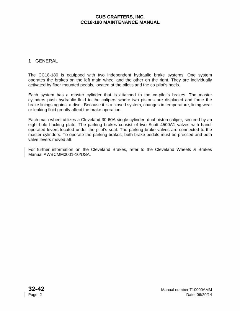
CUB CRAFTERS, INC. CC18-180 MAINTENANCE MANUAL
32-42 Manual number T10000AMM Page: 2 Date: 06/20/14
1 GENERAL
The CC18-180 is equipped with two independent hydraulic brake systems. One system operates the brakes on the left main wheel and the other on the right. They are individually activated by floor-mounted pedals, located at the pilot's and the co-pilot’s heels. Each system has a master cylinder that is attached to the co-pilot’s brakes. The master cylinders push hydraulic fluid to the calipers where two pistons are displaced and force the brake linings against a disc. Because it is a closed system, changes in temperature, lining wear or leaking fluid greatly affect the brake operation. Each main wheel utilizes a Cleveland 30-60A single cylinder, dual piston caliper, secured by an eight-hole backing plate. The parking brakes consist of two Scott 4500A1 valves with hand-operated levers located under the pilot’s seat. The parking brake valves are connected to the master cylinders. To operate the parking brakes, both brake pedals must be pressed and both valve levers moved aft. For further information on the Cleveland Brakes, refer to the Cleveland Wheels & Brakes Manual AWBCMM0001-10/USA.
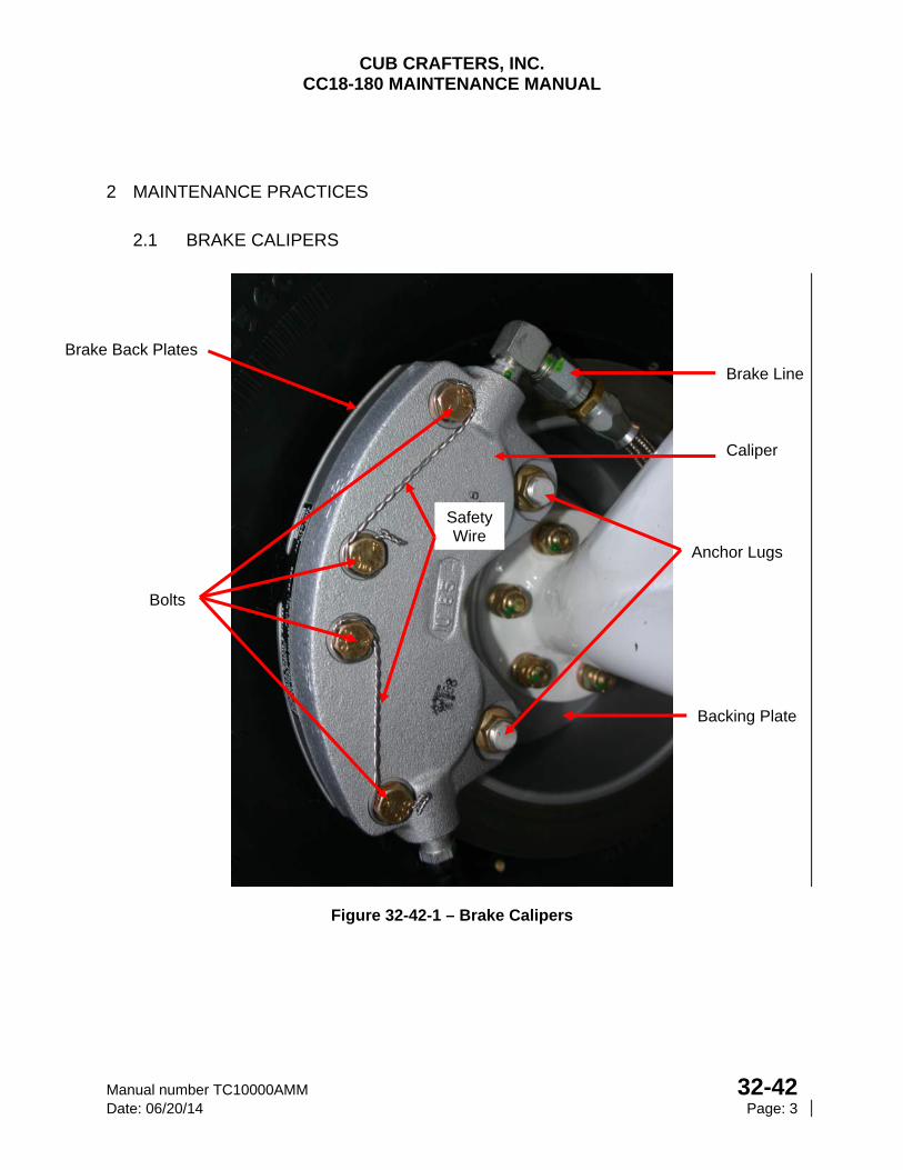
CUB CRAFTERS, INC. CC18-180 MAINTENANCE MANUAL
Manual number TC10000AMM 32-42 Date: 06/20/14 Page: 3
2 MAINTENANCE PRACTICES
2.1 BRAKE CALIPERS
Figure 32-42-1 – Brake Calipers
Brake Line
Caliper
Anchor Lugs
Bolts
Brake Back Plates
Safety Wire
Backing Plate
CUB CRAFTERS, INC. CC18-180 MAINTENANCE MANUAL
32-42 Manual number T10000AMM Page: 4 Date: 06/20/14
2.4.1 REMOVAL
a. Cut the safety wire and remove the brake back plate bolts.
b. Disconnect the brake line from the caliper.
c. Separate the caliper from backing plate.
2.4.2 INSPECTION
a. Inspect the brake linings for loose rivets, cracks and uneven wear.
b. The minimum lining thickness is 0.100 inches.
c. Inspect the calipers for leaks and excessive corrosion.
d. If leaks are present at the pistons, overhaul the caliper.
e. Inspect the brake backing plate for cracks or excessive wear.
f. Replace the parts if their condition so dictates.
2.4.3 INSTALLATION
a. Position the brake pressure plate on the caliper so the linings are facing the disc.
b. Insert the caliper anchor lugs into the backing plate holes.
c. Connect the brake line and tighten. Confirm that there is no resistance on the wheel.
d. Position the brake back plates, insert the bolts, and torque to 65-75 in/lbs.
e. Safety bolts with 0.032 safety wire.
f. Make sure the wheel turns freely.
NOTE Verify that there is positive clearance between the brake pad lining and disc.
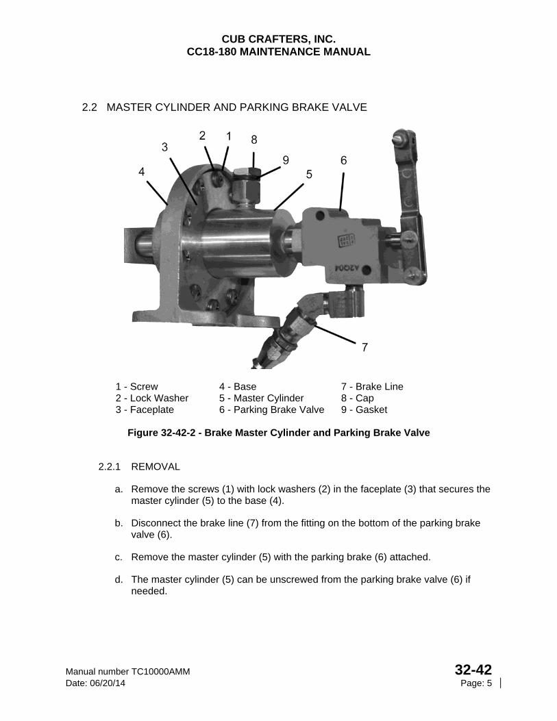
CUB CRAFTERS, INC. CC18-180 MAINTENANCE MANUAL
Manual number TC10000AMM 32-42 Date: 06/20/14 Page: 5
2.2 MASTER CYLINDER AND PARKING BRAKE VALVE
1 - Screw 4 - Base 7 - Brake Line 2 - Lock Washer 5 - Master Cylinder 8 - Cap 3 - Faceplate 6 - Parking Brake Valve 9 - Gasket
Figure 32-42-2 - Brake Master Cylinder and Parking Brake Valve
2.2.1 REMOVAL
a. Remove the screws (1) with lock washers (2) in the faceplate (3) that secures the master cylinder (5) to the base (4).
b. Disconnect the brake line (7) from the fitting on the bottom of the parking brake valve (6).
c. Remove the master cylinder (5) with the parking brake (6) attached.
d. The master cylinder (5) can be unscrewed from the parking brake valve (6) if needed.
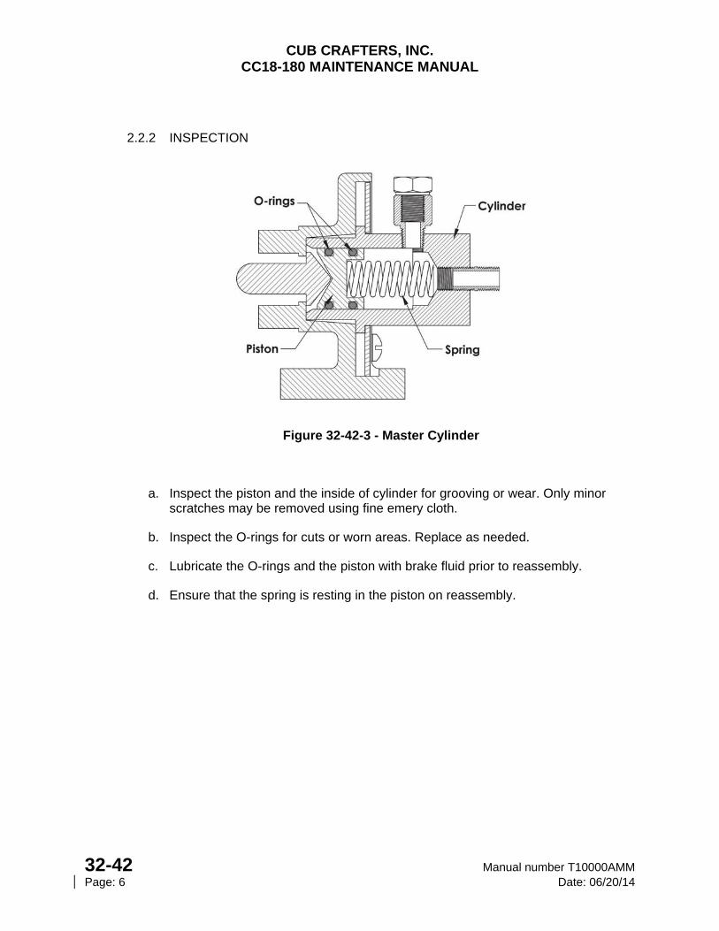
CUB CRAFTERS, INC. CC18-180 MAINTENANCE MANUAL
32-42 Manual number T10000AMM Page: 6 Date: 06/20/14
2.2.2 INSPECTION
Figure 32-42-3 - Master Cylinder
a. Inspect the piston and the inside of cylinder for grooving or wear. Only minor scratches may be removed using fine emery cloth.
b. Inspect the O-rings for cuts or worn areas. Replace as needed.
c. Lubricate the O-rings and the piston with brake fluid prior to reassembly.
d. Ensure that the spring is resting in the piston on reassembly.
CUB CRAFTERS, INC. CC18-180 MAINTENANCE MANUAL
Manual number TC10000AMM 32-42 Date: 06/20/14 Page: 7
2.2.3 INSTALLATION
See Figure 32-42-1
a. If the parking brake valve was separated from the master cylinder, apply a thin coat of EZ TURN Lubricant to the threads on the front fitting. Tighten enough so that it does not to leak but not so tight so as to break the nipple. The parking brake handle and filler standoff must point up.
b. Reconnect the brake line (7) to the fitting on the bottom of the parking brake valve (6) and tighten.
c. Reposition the master cylinder (5) against the base (4).
d. Reinstall the screws (1) with new lock washers (2) under the head through the faceplate (3) into the base (4).
e. Rotate the cylinder (5) so that the vent/filler hole is pointed straight up.
f. Tighten the screws (1), in several steps to 28-32 in/lb. in an alternating pattern.
2.3 PARKING BRAKE VALVE
The parking brake valve locks the brake fluid pressure in the system. It is released when the brakes by pressing the brake pedals or by moving the parking brake lever forward.
2.3.1 REMOVAL
See Figure 32-42-2
a. The parking brake valve (6) is attached to the master cylinder (5). Remove master cylinder (5) as described in 32-42 2.B.(1).
b. Unscrew the parking brake valve (6) from the master cylinder (5).
2.3.2 INSPECTION
a. Visually check for damage or leaks. Replace if condition dictates.
2.3.3 INSTALLATION
a. Reinstall as described in 32-42 2.B.(3).
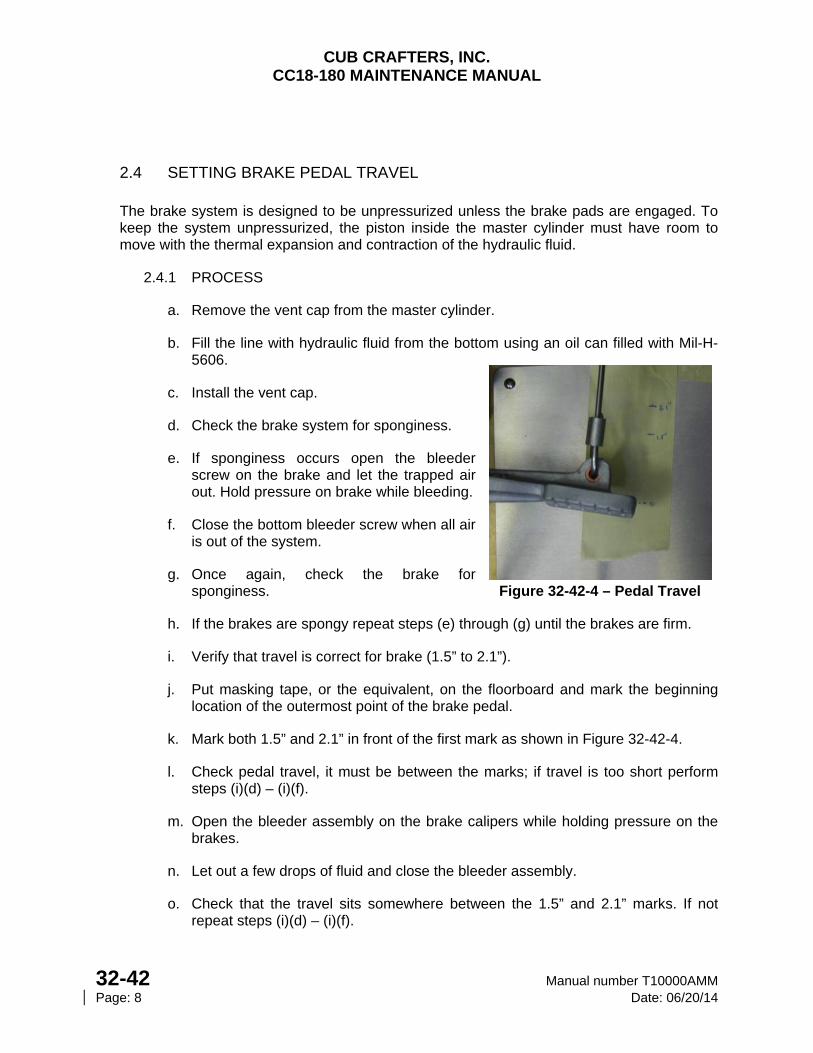
CUB CRAFTERS, INC. CC18-180 MAINTENANCE MANUAL
32-42 Manual number T10000AMM Page: 8 Date: 06/20/14
2.4 SETTING BRAKE PEDAL TRAVEL
The brake system is designed to be unpressurized unless the brake pads are engaged. To keep the system unpressurized, the piston inside the master cylinder must have room to move with the thermal expansion and contraction of the hydraulic fluid.
2.4.1 PROCESS
a. Remove the vent cap from the master cylinder.
b. Fill the line with hydraulic fluid from the bottom using an oil can filled with Mil-H-5606.
c. Install the vent cap.
d. Check the brake system for sponginess.
e. If sponginess occurs open the bleeder screw on the brake and let the trapped air out. Hold pressure on brake while bleeding.
f. Close the bottom bleeder screw when all air is out of the system.
g. Once again, check the brake for sponginess. Figure 32-42-4 – Pedal Travel
h. If the brakes are spongy repeat steps (e) through (g) until the brakes are firm.
i. Verify that travel is correct for brake (1.5” to 2.1”).
j. Put masking tape, or the equivalent, on the floorboard and mark the beginning location of the outermost point of the brake pedal.
k. Mark both 1.5” and 2.1” in front of the first mark as shown in Figure 32-42-4.
l. Check pedal travel, it must be between the marks; if travel is too short perform steps (i)(d) – (i)(f).
m. Open the bleeder assembly on the brake calipers while holding pressure on the brakes.
n. Let out a few drops of fluid and close the bleeder assembly.
o. Check that the travel sits somewhere between the 1.5” and 2.1” marks. If not repeat steps (i)(d) – (i)(f).
CUB CRAFTERS, INC. CC18-180 MAINTENANCE MANUAL
Manual number TC10000AMM 32-60 Date: 05/20/08 Page: 1
32-60 WIPAIRE 2100A AMPHIBIOUS FLOATS
TABLE OF CONTENTS
1. GENERAL .............................................................................................................................. 2
2. MAINTENANCE PRACTICES ............................................................................................... 2
A. INSTALLATION AND REMOVAL OF WIPAIRE 2100A AMPHIBIAN FLOATS .............. 2
(1) AIRCRAFT CONFIGURATION ................................................................................... 2
(2) INSTALLATION AND REMOVAL ............................................................................... 3
B. LAKE AND AIR AMPHIBIAN LANDING GEAR POSITION ADVISORY SYSTEM ........ 3
(1) ADJUSTMENT ............................................................................................................ 3
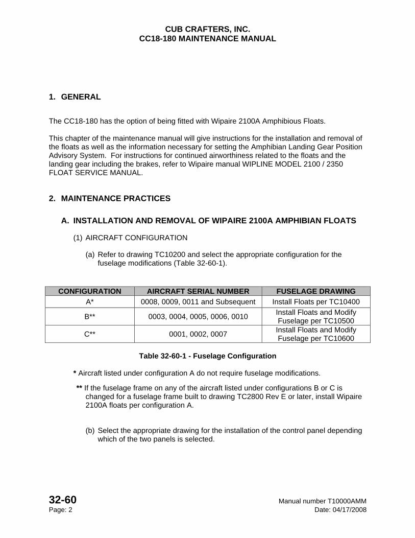
CUB CRAFTERS, INC. CC18-180 MAINTENANCE MANUAL
32-60 Manual number T10000AMM Page: 2 Date: 04/17/2008
1. GENERAL
The CC18-180 has the option of being fitted with Wipaire 2100A Amphibious Floats. This chapter of the maintenance manual will give instructions for the installation and removal of the floats as well as the information necessary for setting the Amphibian Landing Gear Position Advisory System. For instructions for continued airworthiness related to the floats and the landing gear including the brakes, refer to Wipaire manual WIPLINE MODEL 2100 / 2350 FLOAT SERVICE MANUAL.
2. MAINTENANCE PRACTICES
A. INSTALLATION AND REMOVAL OF WIPAIRE 2100A AMPHIBIAN FLOATS
(1) AIRCRAFT CONFIGURATION
(a) Refer to drawing TC10200 and select the appropriate configuration for the fuselage modifications (Table 32-60-1).
CONFIGURATION AIRCRAFT SERIAL NUMBER FUSELAGE DRAWING
A* 0008, 0009, 0011 and Subsequent Install Floats per TC10400
B** 0003, 0004, 0005, 0006, 0010 Install Floats and Modify Fuselage per TC10500
C** 0001, 0002, 0007 Install Floats and Modify Fuselage per TC10600
Table 32-60-1 - Fuselage Configuration
* Aircraft listed under configuration A do not require fuselage modifications.
** If the fuselage frame on any of the aircraft listed under configurations B or C is changed for a fuselage frame built to drawing TC2800 Rev E or later, install Wipaire 2100A floats per configuration A.
(b) Select the appropriate drawing for the installation of the control panel depending which of the two panels is selected.
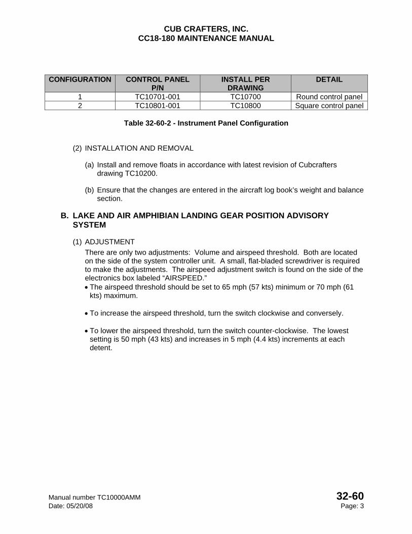
CUB CRAFTERS, INC. CC18-180 MAINTENANCE MANUAL
Manual number TC10000AMM 32-60 Date: 05/20/08 Page: 3
CONFIGURATION CONTROL PANEL P/N
INSTALL PER DRAWING
DETAIL
1 TC10701-001 TC10700 Round control panel 2 TC10801-001 TC10800 Square control panel
Table 32-60-2 - Instrument Panel Configuration
(2) INSTALLATION AND REMOVAL
(a) Install and remove floats in accordance with latest revision of Cubcrafters drawing TC10200.
(b) Ensure that the changes are entered in the aircraft log book’s weight and balance section.
B. LAKE AND AIR AMPHIBIAN LANDING GEAR POSITION ADVISORY SYSTEM
(1) ADJUSTMENT
There are only two adjustments: Volume and airspeed threshold. Both are located on the side of the system controller unit. A small, flat-bladed screwdriver is required to make the adjustments. The airspeed adjustment switch is found on the side of the electronics box labeled “AIRSPEED.” The airspeed threshold should be set to 65 mph (57 kts) minimum or 70 mph (61
kts) maximum. To increase the airspeed threshold, turn the switch clockwise and conversely. To lower the airspeed threshold, turn the switch counter-clockwise. The lowest
setting is 50 mph (43 kts) and increases in 5 mph (4.4 kts) increments at each detent.
CUB CRAFTERS, INC. CC18-180 MAINTENANCE MANUAL
32-60 Manual number T10000AMM Page: 4 Date: 11/15/05
INTENTIONALLY LEFT BLANK
CUB CRAFTERS, INC. CC18-180 MAINTENANCE MANUAL
Manual number T10000AMM 32-61 Date: 11/20/12 Page: 1
32-61 WIPAIRE 2100S SEAPLANE FLOATS
TABLE OF CONTENTS
1. GENERAL .............................................................................................................................. 6
2. MAINTENANCE PRACTICES ............................................................................................... 6
A. INSTALLATION AND REMOVAL OF WIPAIRE 2100S SEAPLANE FLOATS .................. 6
(1) AIRCRAFT CONFIGURATION ................................................................................... 6
(2) INSTALLATION AND REMOVAL ............................................................................... 6
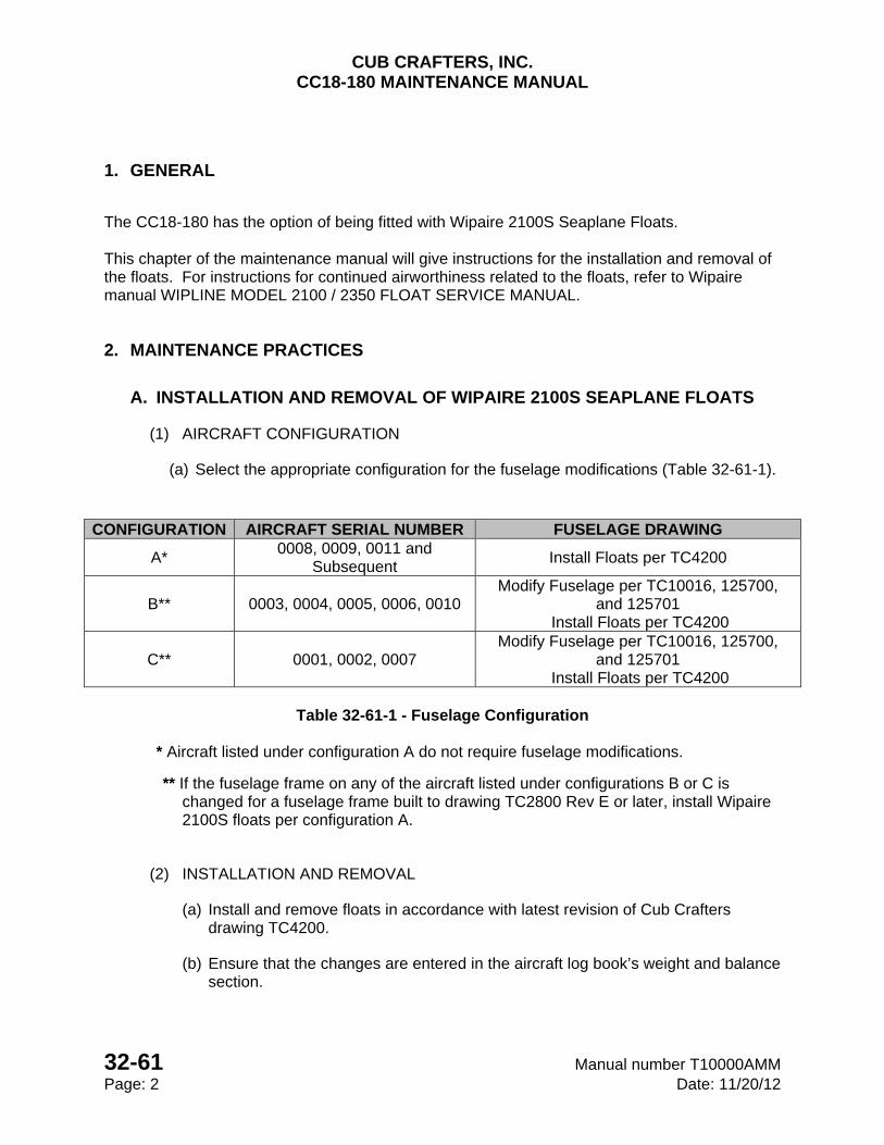
CUB CRAFTERS, INC. CC18-180 MAINTENANCE MANUAL
32-61 Manual number T10000AMM Page: 2 Date: 11/20/12
1. GENERAL
The CC18-180 has the option of being fitted with Wipaire 2100S Seaplane Floats. This chapter of the maintenance manual will give instructions for the installation and removal of the floats. For instructions for continued airworthiness related to the floats, refer to Wipaire manual WIPLINE MODEL 2100 / 2350 FLOAT SERVICE MANUAL.
2. MAINTENANCE PRACTICES
A. INSTALLATION AND REMOVAL OF WIPAIRE 2100S SEAPLANE FLOATS
(1) AIRCRAFT CONFIGURATION
(a) Select the appropriate configuration for the fuselage modifications (Table 32-61-1).
CONFIGURATION AIRCRAFT SERIAL NUMBER FUSELAGE DRAWING
A* 0008, 0009, 0011 and
Subsequent Install Floats per TC4200
B** 0003, 0004, 0005, 0006, 0010 Modify Fuselage per TC10016, 125700,
and 125701 Install Floats per TC4200
C** 0001, 0002, 0007 Modify Fuselage per TC10016, 125700,
and 125701 Install Floats per TC4200
Table 32-61-1 - Fuselage Configuration
* Aircraft listed under configuration A do not require fuselage modifications.
** If the fuselage frame on any of the aircraft listed under configurations B or C is changed for a fuselage frame built to drawing TC2800 Rev E or later, install Wipaire 2100S floats per configuration A.
(2) INSTALLATION AND REMOVAL
(a) Install and remove floats in accordance with latest revision of Cub Crafters drawing TC4200.
(b) Ensure that the changes are entered in the aircraft log book’s weight and balance section.

CHAPTER
33-00
LIGHTS

CUB CRAFTERS, INC. CC18-180 MAINTENANCE MANUAL
Manual number TC10000AMM 33-00 Date: 05/21/14 Page: 1
33-00 LIGHTS
TABLE OF CONTENTS 1 GENERAL ...................................................................................... 2
2. TROUBLESHOOTING ...................................................................... 2
3. MAINTENANCE PRACTICES.............................................................. 2
A. LANDING AND TAXI LIGHT ......................................................... 2
(1) GENERAL ............................................................................... 2
(2) REMOVAL .............................................................................. 3
(3) INSTALLATION ....................................................................... 3
B. NAVIGATION LIGHTS ................................................................. 3
(1) GENERAL ............................................................................... 3
(2) REMOVAL .............................................................................. 3
(3) INSTALLATION ....................................................................... 3
C. ANTI COLLISION ....................................................................... 4
(1) GENERAL ............................................................................... 4
(2) REMOVAL .............................................................................. 4
(3) INSTALLATION ....................................................................... 4
D. CABIN LIGHTING ...................................................................... 4
(1) GENERAL ............................................................................... 4
i) PLACARD LIGHTS ........................................................................ 5
ii) FUEL GAUGE POST LIGHTS ......................................................... 5
iii) INSTRUMENT LIGHTS ................................................................ 6
iv) DOME LIGHT ............................................................................ 6
v) MAP LIGHTS ............................................................................. 6
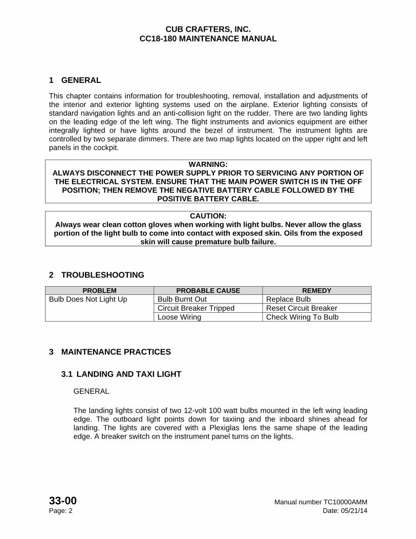
CUB CRAFTERS, INC. CC18-180 MAINTENANCE MANUAL
33-00 Manual number TC10000AMM Page: 2 Date: 05/21/14
1 GENERAL
This chapter contains information for troubleshooting, removal, installation and adjustments of the interior and exterior lighting systems used on the airplane. Exterior lighting consists of standard navigation lights and an anti-collision light on the rudder. There are two landing lights on the leading edge of the left wing. The flight instruments and avionics equipment are either integrally lighted or have lights around the bezel of instrument. The instrument lights are controlled by two separate dimmers. There are two map lights located on the upper right and left panels in the cockpit.
WARNING: ALWAYS DISCONNECT THE POWER SUPPLY PRIOR TO SERVICING ANY PORTION OF THE ELECTRICAL SYSTEM. ENSURE THAT THE MAIN POWER SWITCH IS IN THE OFF
POSITION; THEN REMOVE THE NEGATIVE BATTERY CABLE FOLLOWED BY THE POSITIVE BATTERY CABLE.
CAUTION:
Always wear clean cotton gloves when working with light bulbs. Never allow the glass portion of the light bulb to come into contact with exposed skin. Oils from the exposed
skin will cause premature bulb failure.
2 TROUBLESHOOTING
PROBLEM PROBABLE CAUSE REMEDY Bulb Does Not Light Up Bulb Burnt Out Replace Bulb
Circuit Breaker Tripped Reset Circuit Breaker Loose Wiring Check Wiring To Bulb
3 MAINTENANCE PRACTICES
3.1 LANDING AND TAXI LIGHT
GENERAL
The landing lights consist of two 12-volt 100 watt bulbs mounted in the left wing leading edge. The outboard light points down for taxiing and the inboard shines ahead for landing. The lights are covered with a Plexiglas lens the same shape of the leading edge. A breaker switch on the instrument panel turns on the lights.
CUB CRAFTERS, INC. CC18-180 MAINTENANCE MANUAL
Manual number TC10000AMM 33-00 Date: 05/21/14 Page: 3
(1) REMOVAL
(a) Remove lens trim strips.
(b) Remove 4 screws that hold the front mounting bracket.
(c) Disconnect wires from bulb and remove bulb.
(2) INSTALLATION
(a) Attach bulb to wires. On S/N 0056 and on, verify the polarity on LED lights is correct.
(b) Reposition front mounting plate and secure with 4 screws.
(c) Reattach the lens and trim strips being very careful not to crack the Plexiglas.
A. NAVIGATION LIGHTS
(1) GENERAL
The colors of the navigation lights conform to standard aeronautical practice. The left wing navigation light is red, the right wing navigation light is green and the tail navigation light is white. A breaker switch on the instrument panel turns on all three lights.
(2) REMOVAL
(a) Wing tip - Remove the light shield lens and turn the bulb a quarter turn to unscrew. Be careful not to drop the glass lens or the gasket.
(b) Tail - Remove the lens retainer and lens and turn the bulb a quarter turn to unscrew. Be careful not to drop the glass lens or the gasket.
CAUTION Only approved navigation lights may be installed. The rudder navigation light affects the balance of the rudder.
(3) INSTALLATION
(a) Wing tip - Insert the bulb and reinstall the lens and the shield.
(b) Tail - Insert a bulb and reinstall the lens and the lens retainer.
CUB CRAFTERS, INC. CC18-180 MAINTENANCE MANUAL
33-00 Manual number TC10000AMM Page: 4 Date: 05/21/14
B. ANTI COLLISION
(1) GENERAL
(a) The anti collision beacon is a self-contained flashing light with a red and white lens mounted on the top of the rudder. A breaker switch on the instrument panel turns it on. For aircraft serial number 0056 and on and aircraft modified in accordance with Service Letter 002 a portion of the red lens is masked. This part must face forward.
(2) REMOVAL
(a) Loosen the plastic clamp at the base of light.
(b) Remove the lens.
(c) Remove the bulb.
(3) INSTALLATION
(a) Install the bulb, being careful not to bend or misalign the wire bulb contacts.
(b) Install the lens with the white half facing aft.
(c) Secure by tightening the clamp screw.
C. CABIN LIGHTING
(1) GENERAL
(a) Aircraft serial number 0056 and on and aircraft modified in accordance with Service Letter 002 are equipped with interior lights for night VFR operations. The interior contains lighting for fuel, placards, and instruments as well as a dome light and two maps lights. The map lights and instrument lighting are on the same circuit as the navigation lights. The intensity of the instrument lights may be changed by means of two controls located on the instrument panel.
(b) The upper dimmers control:
Large knob: The backlight to the digital readouts of the engine instruments and placards.
Small Knob: The operational range LED lights on the perimeter of the engine instruments, placards and emergency hand pump light (for amphibious float option only).
c. The lower dimmer controls:
Large knob: Fuel sight gauges and map lights.
Small knob: Navigation instruments.
CUB CRAFTERS, INC. CC18-180 MAINTENANCE MANUAL
Manual number TC10000AMM 33-00 Date: 05/21/14 Page: 5
(c) Aircraft serial numbers 0001 through 0055 were equipped from the factory with two dimmers and one map light. The map light and instrument lighting are on the same circuit as the navigation lights. However, the instrument lights have two knob-controlled rheostats located on the instrument panel. Dimmer #1 controls the instrument lighting and Dimmer #2 controls the warning lights on the oil pressure and temperature gauge. See electrical schematics in Section 24-00 Electrical Power for more information.
i) PLACARD LIGHTS
(1) REMOVAL
(a) If LED’s have been determined as faulty, the faulty LED harness needs replacing. The LED’s are grouped onto the following harnesses:
(a) Fuel selector and trim indicator.
(b) Mixture and dimmer knobs.
(c) Circuit breakers and instrument panel switches.
(b) Remove the LED’s from the rear of placards by pulling the bulbs from the fiber optic sleeves. (Fuel selector and trim indicator placards will need to be unscrewed first)
(c) Disconnect and remove the LED harness.
(2) INSTALLATION
(a) Replace wiring harness.
(b) Reattach light(s) to fiber optic sleeves.
(c) Install placard if necessary.
ii) FUEL GAUGE POST LIGHTS
(1) REMOVAL
(a) Disconnect wire from post light.
(b) Unscrew nut and lock washer from outboard face of wing root panel.
(c) Remove post light.
(2) INSTALLATION
(a) Install post light.
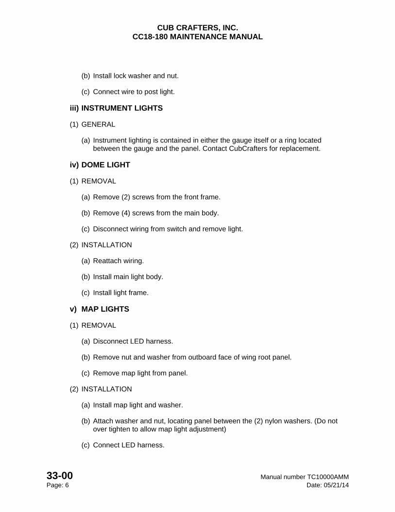
CUB CRAFTERS, INC. CC18-180 MAINTENANCE MANUAL
33-00 Manual number TC10000AMM Page: 6 Date: 05/21/14
(b) Install lock washer and nut.
(c) Connect wire to post light.
iii) INSTRUMENT LIGHTS
(1) GENERAL
(a) Instrument lighting is contained in either the gauge itself or a ring located between the gauge and the panel. Contact CubCrafters for replacement.
iv) DOME LIGHT
(1) REMOVAL
(a) Remove (2) screws from the front frame.
(b) Remove (4) screws from the main body.
(c) Disconnect wiring from switch and remove light.
(2) INSTALLATION
(a) Reattach wiring.
(b) Install main light body.
(c) Install light frame.
v) MAP LIGHTS
(1) REMOVAL
(a) Disconnect LED harness.
(b) Remove nut and washer from outboard face of wing root panel.
(c) Remove map light from panel.
(2) INSTALLATION
(a) Install map light and washer.
(b) Attach washer and nut, locating panel between the (2) nylon washers. (Do not over tighten to allow map light adjustment)
(c) Connect LED harness.
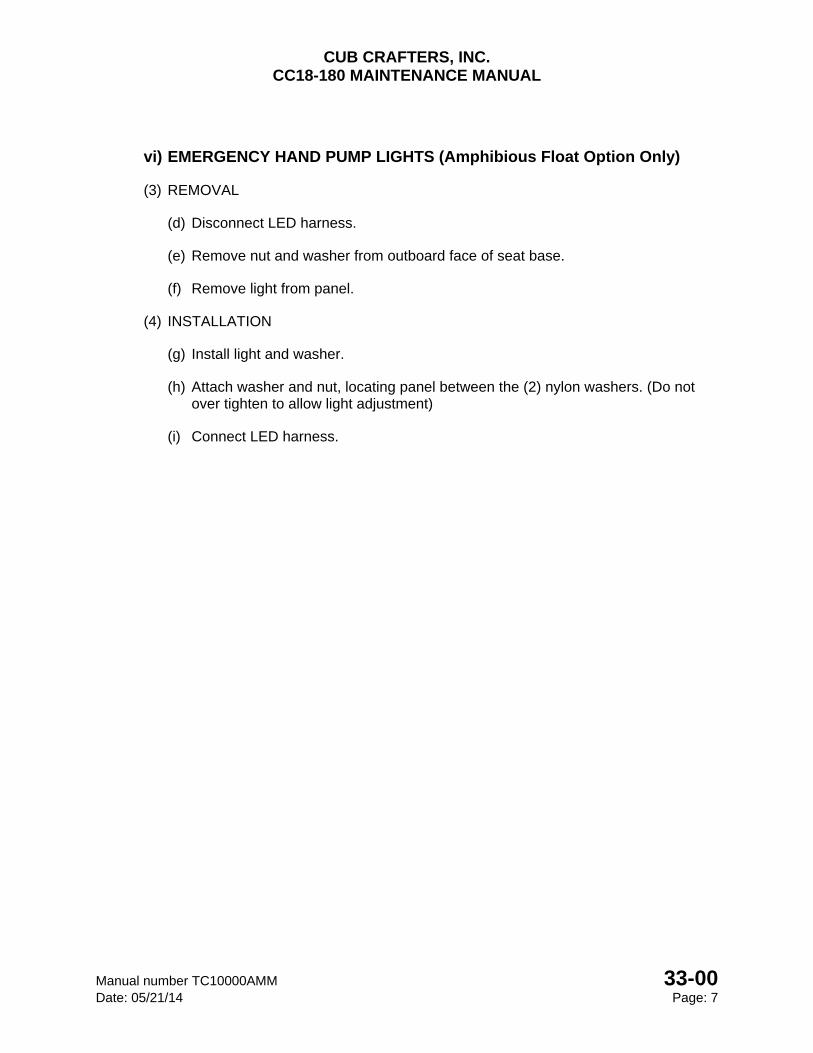
CUB CRAFTERS, INC. CC18-180 MAINTENANCE MANUAL
Manual number TC10000AMM 33-00 Date: 05/21/14 Page: 7
vi) EMERGENCY HAND PUMP LIGHTS (Amphibious Float Option Only)
(3) REMOVAL
(d) Disconnect LED harness.
(e) Remove nut and washer from outboard face of seat base.
(f) Remove light from panel.
(4) INSTALLATION
(g) Install light and washer.
(h) Attach washer and nut, locating panel between the (2) nylon washers. (Do not over tighten to allow light adjustment)
(i) Connect LED harness.
CUB CRAFTERS, INC. CC18-180 MAINTENANCE MANUAL
33-00 Manual number TC10000AMM Page: 8 Date: 05/21/14
INTENTIONALLY LEFT BLANK
CHAPTER
34-00
PITOT STATIC

CUB CRAFTERS, INC. CC18-180 MAINTENANCE MANUAL
Manual number TC100000AMM 34-00 Date: 05/20/08 Page: 1
34-00 PITOT STATIC SYSTEM
TABLE OF CONTENTS 1. GENERAL ............................................................................................................................. 2
2. TROUBLESHOOTING .......................................................................................................... 5
3. MAINTENANCE PRACTICES .............................................................................................. 6
A. ATC TRANSPONDER TEST ............................................................................................ 6
B. ALTIMETER STATIC SYSTEM TEST AND INSPECTION ............................................... 6
(1) STATIC SYSTEM LEAK TEST ................................................................................... 6
(2) PITOT SYSTEM LEAK CHECK .................................................................................. 6
CUB CRAFTERS, INC. CC18-180 MAINTENANCE MANUAL
34-00 Manual numberTC10000AMM Page: 2 Date: 05/20/08
1. GENERAL
This section covers the Pitot and Static systems. These systems provide the information required by the airspeed indicator, the altimeter, the vertical speed indicator and the altitude encoder. The pitot system senses dynamic pressure through a tube that is aligned with the flow of air and is located under the left wing. The tube is heated. The static pressure orifices are located on the both sides of the fuselage, just behind the engine. There are two orifices to counteract the effects of yaw. The alternate static source valve is found on the lower left side of the instrument panel. It provides an alternate source of static air pressure from inside the cabin in the event the normal static sources are plugged.
NOTE The alternate static source is to be used when the normal system is inoperative or
malfunctioning. When alternate static air is used, instrument readings will vary from normal readings due to static air being obtained from the cabin.
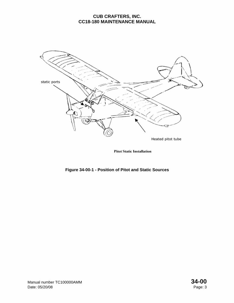
CUB CRAFTERS, INC. CC18-180 MAINTENANCE MANUAL
Manual number TC100000AMM 34-00 Date: 05/20/08 Page: 3
Figure 34-00-1 - Position of Pitot and Static Sources
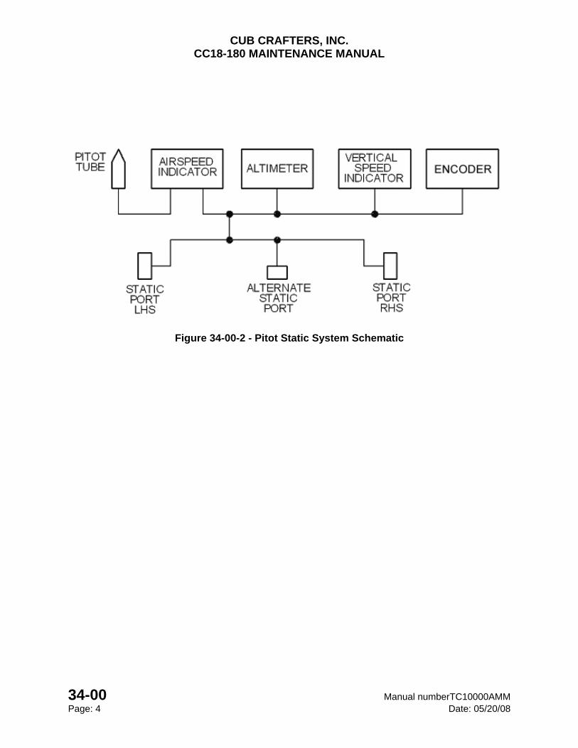
CUB CRAFTERS, INC. CC18-180 MAINTENANCE MANUAL
34-00 Manual numberTC10000AMM Page: 4 Date: 05/20/08
Figure 34-00-2 - Pitot Static System Schematic
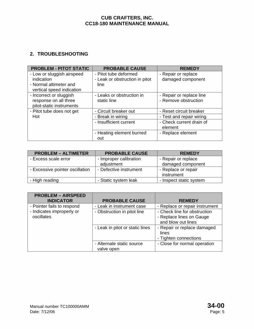
CUB CRAFTERS, INC. CC18-180 MAINTENANCE MANUAL
Manual number TC100000AMM 34-00 Date: 7/12/06 Page: 5
2. TROUBLESHOOTING
PROBLEM - PITOT STATIC PROBABLE CAUSE REMEDY - Low or sluggish airspeed indication - Normal altimeter and vertical speed indication
- Pitot tube deformed - Leak or obstruction in pitot line
- Repair or replace damaged component
- Incorrect or sluggish response on all three pitot-static instruments
- Leaks or obstruction in static line
- Repair or replace line - Remove obstruction
- Pitot tube does not get Hot
- Circuit breaker out - Reset circuit breaker - Break in wiring - Test and repair wiring - Insufficient current - Check current drain of
element - Heating element burned out
- Replace element
PROBLEM – ALTIMETER PROBABLE CAUSE REMEDY - Excess scale error - Improper calibration
adjustment - Repair or replace damaged component
- Excessive pointer oscillation - Defective instrument - Replace or repair instrument
- High reading - Static system leak - Inspect static system
PROBLEM – AIRSPEED INDICATOR PROBABLE CAUSE REMEDY
- Pointer fails to respond - Indicates improperly or oscillates
- Leak in instrument case - Replace or repair instrument - Obstruction in pitot line - Check line for obstruction
- Replace lines on Gauge and blow out lines
- Leak in pitot or static lines - Repair or replace damaged lines - Tighten connections
- Alternate static source valve open
- Close for normal operation
CUB CRAFTERS, INC. CC18-180 MAINTENANCE MANUAL
34-00 Manual numberTC10000AMM Page: 6 Date: 05/20/08
3. MAINTENANCE PRACTICES
A. ATC TRANSPONDER TEST A transponder test is required every 24 calendar months in accordance with 14 CFR 91.413. The transponder is located in the instrument panel at the bottom of the radio stack. The encoder is mounted to the top of the front right interior panel underneath the instrument panel.
B. ALTIMETER STATIC SYSTEM TEST AND INSPECTION Static system tests must comply with the requirements of 14 CFR 91.411 and be performed by a rated repair station with the appropriate test equipment. A static leak test should be accomplished whenever a connection has been loosened or an instrument replaced.
(1) STATIC SYSTEM LEAK TEST
(a) Connect the test equipment directly to a static port and seal off the opposite static port with plastic tape.
CAUTION
Do not blow air through the line toward the instrument panel. This may seriously damage the instruments.
(b) Apply a vacuum equivalent to 1,000 feet altitude, (differential pressure of approximately 1.07 inches of mercury or 14.5 inches of water) and hold.
(c) After 1 minute, check that the leak has not exceeded the equivalent of 100 feet of altitude (decrease in differential pressure of approximately 0.0105 inches of mercury or 1.43 inches of water).
(d) Unseal the static port and disconnect the equipment.
(2) PITOT SYSTEM LEAK CHECK
(a) Seal the drain hole on the bottom of the pitot tube and connect the pitot pressure opening to a tee to which a source of pressure and manometer or reliable indicator is connected.
(b) Restrain the hoses to prevent them from moving excessively when the pressure is applied.
(c) Apply pressure until the airspeed indicator indicates 150 m.p.h. (130 kts) (equivalent to a differential pressure 1.1 inches of mercury or 14.9 inches of water). Hold this pressure and clamp off from the source of pressure. After 1
CUB CRAFTERS, INC. CC18-180 MAINTENANCE MANUAL
Manual number TC100000AMM 34-00 Date: 05/20/08 Page: 7
minute, the leakage should not exceed 10 m.p.h. (8.7 kts) (decrease in differential pressure of approximately 0.15 inches of mercury or 2.04 inches of water).
CAUTION:
To avoid rupturing the diaphragm of the airspeed indicator, apply pressure slowly and do not build up excessive pressure in the line. Release pressure slowly to avoid damaging
the airspeed indicator.
(d) If the airspeed indicator reading declines, check the system for leaky hoses and loose connections.
(e) Inspect the hoses for signs of deterioration, particularly at bends and at the connection points to the pitot mast and airspeed indicator. Replace any hoses that are cracked or hardened. Any time a hose is replaced, perform a pressure check.
CAUTION
Do not apply suction to pitot lines.
(f) Unseal the drain hole and disconnect the equipment.

CUB CRAFTERS, INC. CC18-180 MAINTENANCE MANUAL
34-00 Manual numberTC10000AMM Page: 8 Date: 05/20/08
INTENTIONALLY LEFT BLANK
CHAPTER
37-00
VACUUM SYSTEM

CUB CRAFTERS, INC. CC18-180 MAINTENANCE MANUAL
Manual number TC10000AMM 37-00 Date: 05/20/08 Page: 1
37-00 VACUUM SYSTEM TABLE OF CONTENTS 1. GENERAL ......................................................................................................................... 2
2. MAINTENANCE PRACTICES .......................................................................................... 3
A. VACUUM PUMP ............................................................................................................... 3
(1) REMOVAL ..................................................................................................................... 3
(2) INSPECTION ................................................................................................................ 3
(3) INSTALLATION ............................................................................................................. 3
B. AIR FILTER ....................................................................................................................... 3
(1) REMOVAL ..................................................................................................................... 3
(2) INSPECTION ................................................................................................................ 3
(3) INSTALLATION ............................................................................................................. 3
C. TROUBLESHOOTING ...................................................................................................... 4
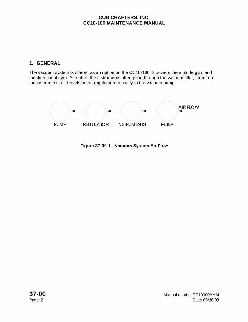
CUB CRAFTERS, INC. CC18-180 MAINTENANCE MANUAL
37-00 Manual number TC10000AMM Page: 2 Date: 05/20/08
1. GENERAL
The vacuum system is offered as an option on the CC18-180. It powers the attitude gyro and the directional gyro. Air enters the instruments after going through the vacuum filter, then from the instruments air travels to the regulator and finally to the vacuum pump.
PUMP REGULATOR INSTRUMENTS
AIR FLOW
FILTER
Figure 37-00-1 - Vacuum System Air Flow
CUB CRAFTERS, INC. CC18-180 MAINTENANCE MANUAL
Manual number TC10000AMM 37-00 Date: 05/20/08 Page: 3
2. MAINTENANCE PRACTICES
A. VACUUM PUMP
(1) REMOVAL
(a) Disconnect the hoses
(b) Unbolt from engine
(2) INSPECTION
(a) Check vacuum pressure: Normal reading us between 4.8 and 5.2 inches of mercury. Check to see if shaft is sheared.
(3) INSTALLATION
(a) Install pump with a new gasket
(b) Torque nuts to manufacturers recommended values
(c) Reconnect hoses
B. AIR FILTER
(1) REMOVAL
(a) Remove bolt from top of air filter
(b) Pull out
(2) INSPECTION
(a) Visually inspect filter for excessive contamination
(3) INSTALLATION
(a) Install new air filter
(b) Reinstall bolt
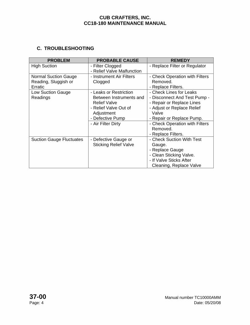
CUB CRAFTERS, INC. CC18-180 MAINTENANCE MANUAL
37-00 Manual number TC10000AMM Page: 4 Date: 05/20/08
C. TROUBLESHOOTING
PROBLEM PROBABLE CAUSE REMEDY High Suction - Filter Clogged
- Relief Valve Malfunction - Replace Filter or Regulator
Normal Suction Gauge Reading, Sluggish or Erratic
- Instrument Air Filters Clogged
- Check Operation with Filters Removed. - Replace Filters.
Low Suction Gauge Readings
- Leaks or Restriction Between Instruments and Relief Valve - Relief Valve Out of Adjustment - Defective Pump
- Check Lines for Leaks - Disconnect And Test Pump - - Repair or Replace Lines - Adjust or Replace Relief Valve - Repair or Replace Pump.
- Air Filter Dirty - Check Operation with Filters Removed. - Replace Filters.
Suction Gauge Fluctuates - Defective Gauge or Sticking Relief Valve
- Check Suction With Test Gauge. - Replace Gauge - Clean Sticking Valve. - If Valve Sticks After Cleaning, Replace Valve
CHAPTER
51-00
STRUCTURES

CUB CRAFTERS, INC. CC18-180 MAINTENANCE MANUAL
Manual number TC100000AMM 51-00 Date: 05/20/08 Page: 1
51-00 STRUCTURES TABLE OF CONTENTS 1. GENERAL ......................................................................................................................... 2
2. APPROVED FABRIC REPAIR MATERIALS .................................................................... 2
3. MAINTENANCE PRACTICES .......................................................................................... 2
A. INSPECTION OF FABRIC ............................................................................................ 2
B. FABRIC REPAIRS ........................................................................................................ 3
(1) SIZE OF REPAIR AREA ........................................................................................... 3
(2) PATCH REPAIR LESS THAN 8 INCHES ................................................................. 4
(3) PATCH REPAIR MORE THAN 8 INCHES ................................................................ 5
(4) STITCHING ............................................................................................................... 6
CUB CRAFTERS, INC. CC18-180 MAINTENANCE MANUAL
51-00 Manual number TC10000AMM Page: 2 Date: 05/20/08
1. GENERAL
This chapter contains information and procedures applicable to all fabric repairs as well as information and procedures for aircraft painting and priming.
2. APPROVED FABRIC REPAIR MATERIALS
Description Supplier Methyl Ethyl Ketone (MEK) Local Supplier Poly-Fiber Poly-Fiber Aircraft Coating Poly-Tak Poly-Fiber Aircraft Coating Poly-Brush Poly-Fiber Aircraft Coating Poly-Spray Poly-Fiber Aircraft Coating Flat Rib Lace Cord Poly-Fiber Aircraft Coating LOCTITE Depend 330 Adhesive Cub Crafters or Local Supplier
3. MAINTENANCE PRACTICES
A. INSPECTION OF FABRIC
The polyester fabric used on the CC18-180 is very durable and its longevity depends on maintaining the coating in good shape. Ultraviolet radiation (in other words, direct sunlight) is the main cause of deterioration of the fabric. The fabric is treated at the factory to protect it from this type of radiation.
The fabric covering on the CC18-180 meets the requirements of TSO C-15d/AMS which stipulate that the minimum breaking strength of the fabric should be at least 56 lbs. Testing fabric requires skill and experience and should only be performed by a qualified person who has experience in this matter.
The CC-18-180 has been covered using a process that is proprietary to Cub Crafters. It is similar to the Poly-Fiber Aircraft coating, more commonly referred to as the Stits method.
CUB CRAFTERS, INC. CC18-180 MAINTENANCE MANUAL
Manual number TC100000AMM 51-00 Date: 05/20/08 Page: 3
B. FABRIC REPAIRS
The decision to repair damage on the fabric or whether to replace the covering on the part will depend upon the extent of the damage and should take into account the aesthetics of the repair.
These repairs require the use of an iron to shrink the fabric. It is very important that only a good quality clothing iron is used.
WARNING
GROUND THE STRUCTURE BEING SANDED OR SPRAYED TO PREVENT STATIC ELECTRICITY FROM IGNITING VAPORES AND
EXPLODING!
(1) SIZE OF REPAIR AREA
If the length of the damaged area is 8 inches or more, the patch must overlap the old
fabric by at least 2 inches. Repairs longer than 8 inches require at least a 2 inch wide finishing tape over the seams. These tapes should be centered over the seam of the patch.
If the length of the damaged area is less than 8 inches in length, the patch must overlap
the old fabric by at least 1 inch. Finishing tapes are not required over the glued seams unless the patch is on top of the wing.
For small fabric repairs such as stick or stone damage, where the holes are ½ inch long
or less, a patch of already doped and painted fabric with the edges pinked can be used. An overlap of at least ½ inch of patch material over ½ inch of old fabric on all sides is required and it must be secured with Loctite Depend 330 Adhesive or a suitable equivalent.
Any stitching that is removed during repair must be replaced. Use the methods given in
section 3.(B)(4).
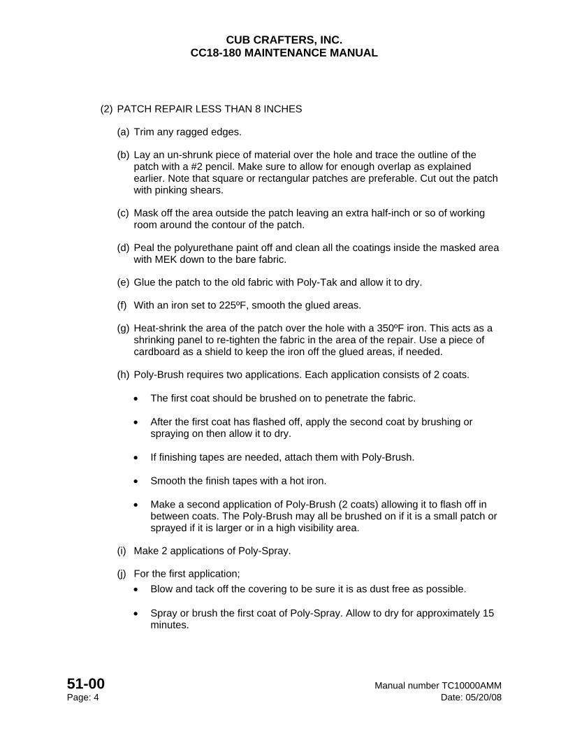
CUB CRAFTERS, INC. CC18-180 MAINTENANCE MANUAL
51-00 Manual number TC10000AMM Page: 4 Date: 05/20/08
(2) PATCH REPAIR LESS THAN 8 INCHES
(a) Trim any ragged edges.
(b) Lay an un-shrunk piece of material over the hole and trace the outline of the patch with a #2 pencil. Make sure to allow for enough overlap as explained earlier. Note that square or rectangular patches are preferable. Cut out the patch with pinking shears.
(c) Mask off the area outside the patch leaving an extra half-inch or so of working room around the contour of the patch.
(d) Peal the polyurethane paint off and clean all the coatings inside the masked area with MEK down to the bare fabric.
(e) Glue the patch to the old fabric with Poly-Tak and allow it to dry.
(f) With an iron set to 225ºF, smooth the glued areas.
(g) Heat-shrink the area of the patch over the hole with a 350ºF iron. This acts as a shrinking panel to re-tighten the fabric in the area of the repair. Use a piece of cardboard as a shield to keep the iron off the glued areas, if needed.
(h) Poly-Brush requires two applications. Each application consists of 2 coats.
The first coat should be brushed on to penetrate the fabric.
After the first coat has flashed off, apply the second coat by brushing or spraying on then allow it to dry.
If finishing tapes are needed, attach them with Poly-Brush.
Smooth the finish tapes with a hot iron.
Make a second application of Poly-Brush (2 coats) allowing it to flash off in between coats. The Poly-Brush may all be brushed on if it is a small patch or sprayed if it is larger or in a high visibility area.
(i) Make 2 applications of Poly-Spray.
(j) For the first application;
Blow and tack off the covering to be sure it is as dust free as possible.
Spray or brush the first coat of Poly-Spray. Allow to dry for approximately 15 minutes.
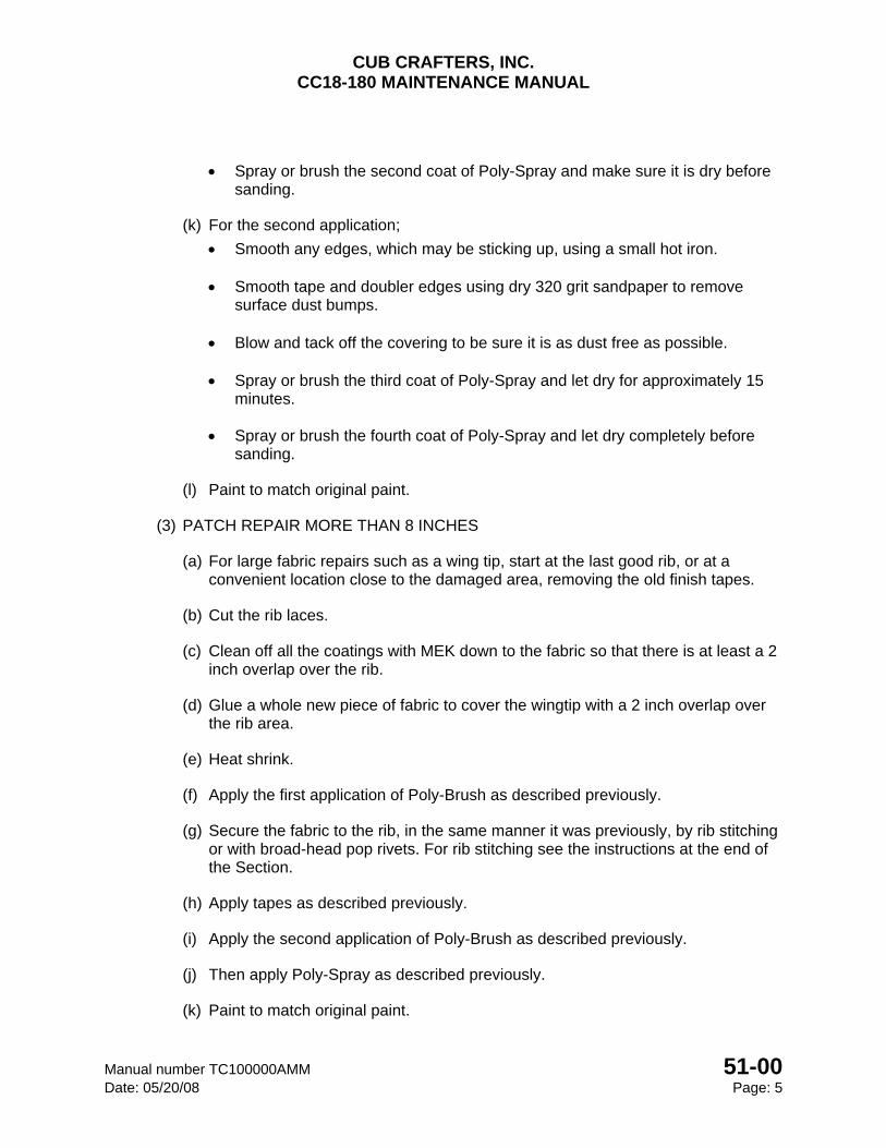
CUB CRAFTERS, INC. CC18-180 MAINTENANCE MANUAL
Manual number TC100000AMM 51-00 Date: 05/20/08 Page: 5
Spray or brush the second coat of Poly-Spray and make sure it is dry before sanding.
(k) For the second application;
Smooth any edges, which may be sticking up, using a small hot iron.
Smooth tape and doubler edges using dry 320 grit sandpaper to remove surface dust bumps.
Blow and tack off the covering to be sure it is as dust free as possible.
Spray or brush the third coat of Poly-Spray and let dry for approximately 15
minutes.
Spray or brush the fourth coat of Poly-Spray and let dry completely before sanding.
(l) Paint to match original paint.
(3) PATCH REPAIR MORE THAN 8 INCHES
(a) For large fabric repairs such as a wing tip, start at the last good rib, or at a convenient location close to the damaged area, removing the old finish tapes.
(b) Cut the rib laces.
(c) Clean off all the coatings with MEK down to the fabric so that there is at least a 2 inch overlap over the rib.
(d) Glue a whole new piece of fabric to cover the wingtip with a 2 inch overlap over the rib area.
(e) Heat shrink.
(f) Apply the first application of Poly-Brush as described previously.
(g) Secure the fabric to the rib, in the same manner it was previously, by rib stitching or with broad-head pop rivets. For rib stitching see the instructions at the end of the Section.
(h) Apply tapes as described previously.
(i) Apply the second application of Poly-Brush as described previously.
(j) Then apply Poly-Spray as described previously.
(k) Paint to match original paint.
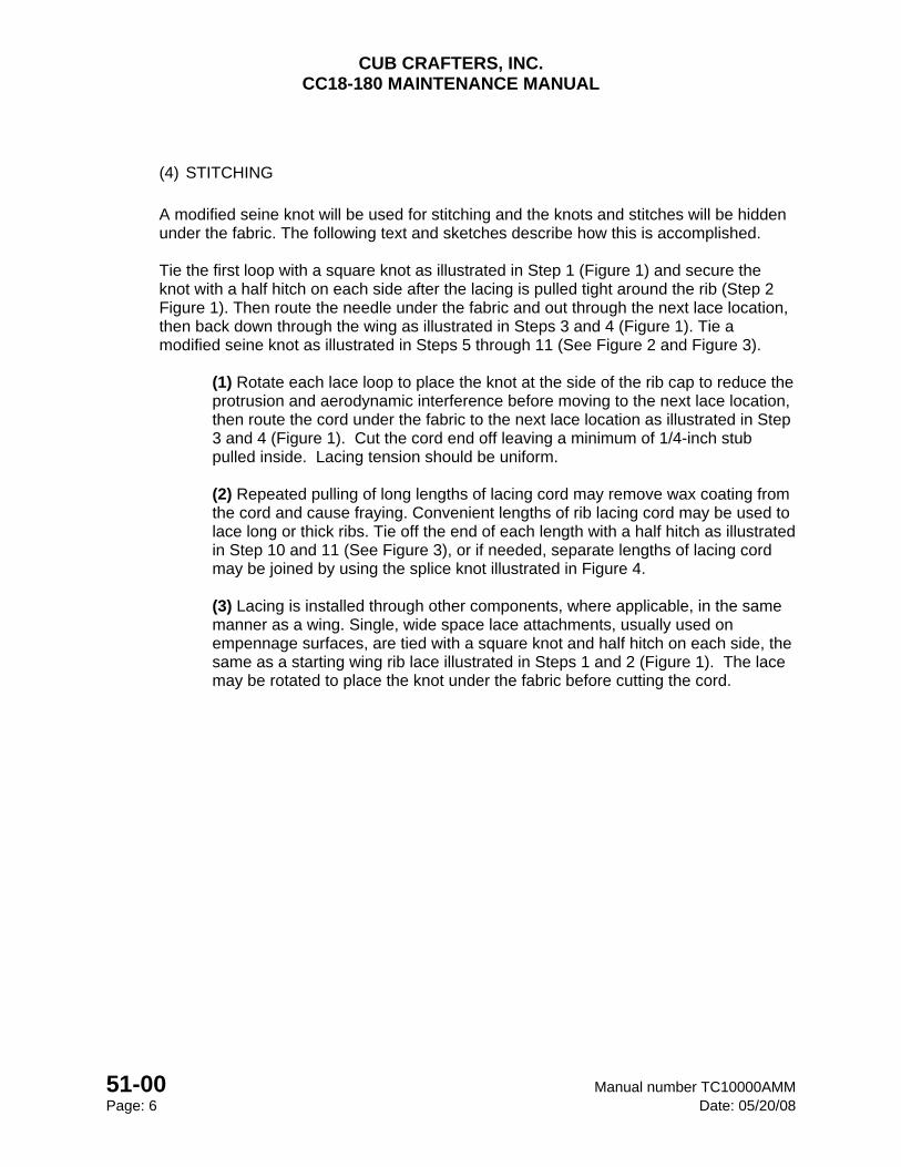
CUB CRAFTERS, INC. CC18-180 MAINTENANCE MANUAL
51-00 Manual number TC10000AMM Page: 6 Date: 05/20/08
(4) STITCHING
A modified seine knot will be used for stitching and the knots and stitches will be hidden under the fabric. The following text and sketches describe how this is accomplished.
Tie the first loop with a square knot as illustrated in Step 1 (Figure 1) and secure the knot with a half hitch on each side after the lacing is pulled tight around the rib (Step 2 Figure 1). Then route the needle under the fabric and out through the next lace location, then back down through the wing as illustrated in Steps 3 and 4 (Figure 1). Tie a modified seine knot as illustrated in Steps 5 through 11 (See Figure 2 and Figure 3).
(1) Rotate each lace loop to place the knot at the side of the rib cap to reduce the protrusion and aerodynamic interference before moving to the next lace location, then route the cord under the fabric to the next lace location as illustrated in Step 3 and 4 (Figure 1). Cut the cord end off leaving a minimum of 1/4-inch stub pulled inside. Lacing tension should be uniform.
(2) Repeated pulling of long lengths of lacing cord may remove wax coating from the cord and cause fraying. Convenient lengths of rib lacing cord may be used to lace long or thick ribs. Tie off the end of each length with a half hitch as illustrated in Step 10 and 11 (See Figure 3), or if needed, separate lengths of lacing cord may be joined by using the splice knot illustrated in Figure 4.
(3) Lacing is installed through other components, where applicable, in the same manner as a wing. Single, wide space lace attachments, usually used on empennage surfaces, are tied with a square knot and half hitch on each side, the same as a starting wing rib lace illustrated in Steps 1 and 2 (Figure 1). The lace may be rotated to place the knot under the fabric before cutting the cord.
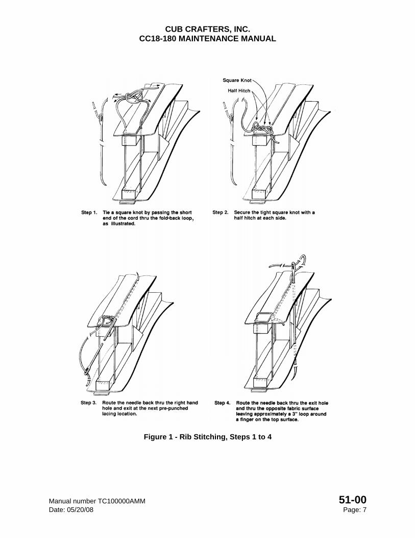
CUB CRAFTERS, INC. CC18-180 MAINTENANCE MANUAL
Manual number TC100000AMM 51-00 Date: 05/20/08 Page: 7
Figure 1 - Rib Stitching, Steps 1 to 4
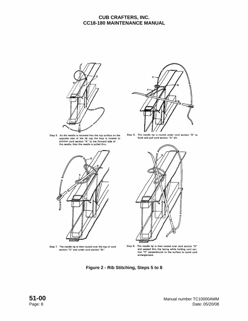
CUB CRAFTERS, INC. CC18-180 MAINTENANCE MANUAL
51-00 Manual number TC10000AMM Page: 8 Date: 05/20/08
Figure 2 - Rib Stitching, Steps 5 to 8
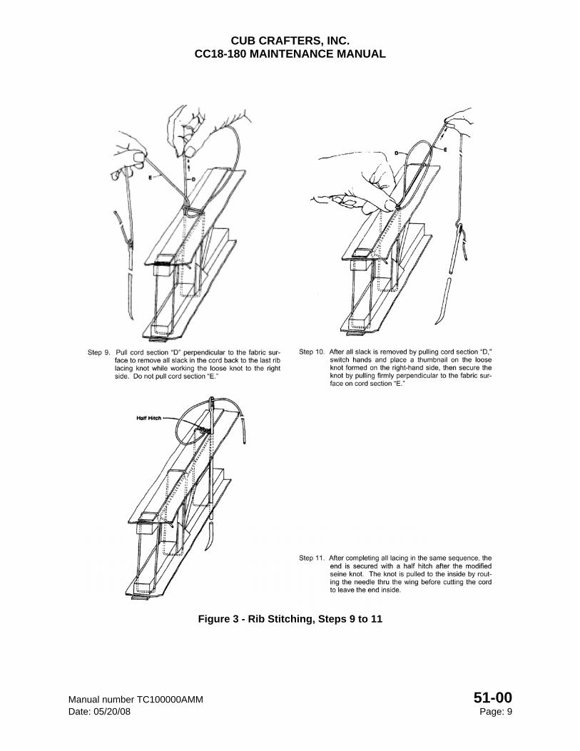
CUB CRAFTERS, INC. CC18-180 MAINTENANCE MANUAL
Manual number TC100000AMM 51-00 Date: 05/20/08 Page: 9
Figure 3 - Rib Stitching, Steps 9 to 11
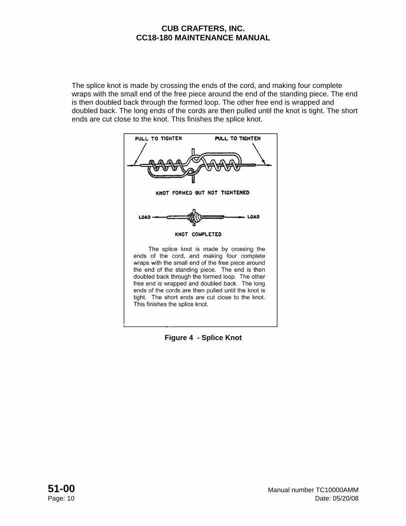
CUB CRAFTERS, INC. CC18-180 MAINTENANCE MANUAL
51-00 Manual number TC10000AMM Page: 10 Date: 05/20/08
The splice knot is made by crossing the ends of the cord, and making four complete wraps with the small end of the free piece around the end of the standing piece. The end is then doubled back through the formed loop. The other free end is wrapped and doubled back. The long ends of the cords are then pulled until the knot is tight. The short ends are cut close to the knot. This finishes the splice knot.
Figure 4 - Splice Knot
CHAPTER
57-00
WINGS

CUB CRAFTERS, INC. CC18-180 MAINTENANCE MANUAL
Manual number TC10000AMM 57-00 Date: 04/15/05 Page: 1
57-00 WINGS
TABLE OF CONTENTS 1. GENERAL ......................................................................................................................... 2
2. MAINTENANCE PRACTICES ........................................................................................... 3
A. SERVICING ................................................................................................................... 3
(1) REMOVAL .................................................................................................................. 5
(2) INSTALLATION .......................................................................................................... 6
B. RIGGING THE WINGS .................................................................................................. 8
(1) PREPARATION .......................................................................................................... 8
(2) DIHEDRAL ANGLE .................................................................................................... 8
(3) WASHOUT ANGLE .................................................................................................... 9
C. VORTEX GENERATORS ............................................................................................ 10
CUB CRAFTERS, INC. CC18-180 MAINTENANCE MANUAL
57-00 Manual number TC10000AMM Page 2 Date: 04/15/05
1. GENERAL
The wing is covered with fabric, has two extruded aluminum spars, pressed aluminum ribs and aluminum leading and trailing edge skins. Rigidity is provided by drag wires and drag braces. The left wing panel houses a landing light. The stall-warning switch is installed on the leading edge of the right wing. The wing incorporates slotted wing flaps inboard of the ailerons.
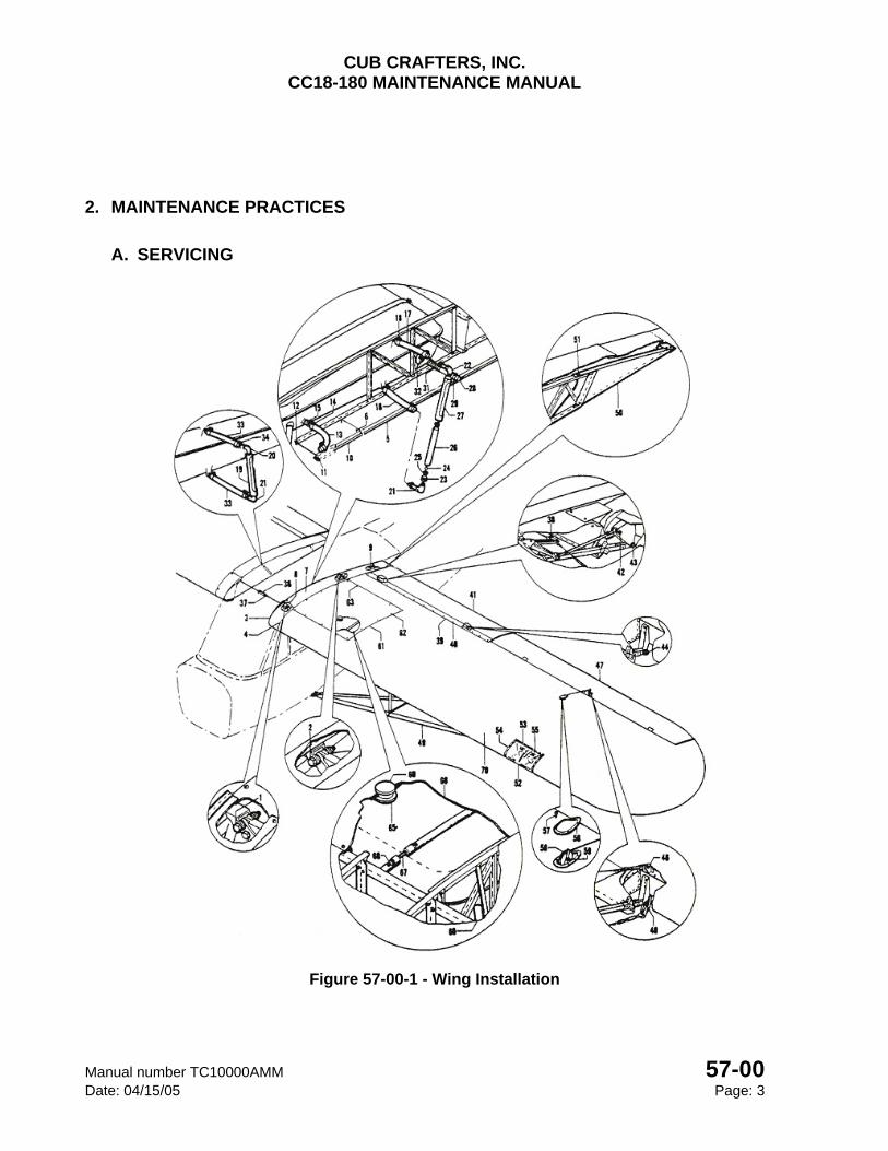
CUB CRAFTERS, INC. CC18-180 MAINTENANCE MANUAL
Manual number TC10000AMM 57-00 Date: 04/15/05 Page: 3
2. MAINTENANCE PRACTICES
A. SERVICING
Figure 57-00-1 - Wing Installation
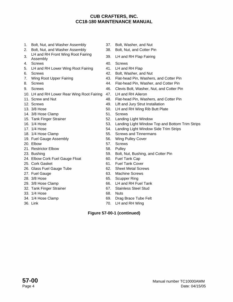
CUB CRAFTERS, INC. CC18-180 MAINTENANCE MANUAL
57-00 Manual number TC10000AMM Page 4 Date: 04/15/05
1. Bolt, Nut, and Washer Assembly 37. Bolt, Washer, and Nut 2. Bolt, Nut, and Washer Assembly 38. Bolt, Nut, and Cotter Pin
3. LH and RH Front Wing Root Fairing Assembly
39. LH and RH Flap Fairing
4. Screws 40. Screws 5. LH and RH Lower Wing Root Fairing 41. LH and RH Flap 6. Screws 42. Bolt, Washer, and Nut 7. Wing Root Upper Fairing 43. Flat-head Pin, Washers, and Cotter Pin 8. Screws 44. Flat-head Pin, Washer, and Cotter Pin
9. Screws 46. Clevis Bolt, Washer, Nut, and Cotter Pin
10. LH and RH Lower Rear Wing Root Fairing 47. LH and RH Aileron 11. Screw and Nut 48. Flat-head Pin, Washers, and Cotter Pin 12. Screws 49. Lift and Jury Strut Installation 13. 3/8 Hose 50. LH and RH Wing Rib Butt Plate 14. 3/8 Hose Clamp 51. Screws 15. Tank Finger Strainer 52. Landing Light Window 16. 1/4 Hose 53. Landing Light Window Top and Bottom Trim Strips17. 1/4 Hose 54. Landing Light Window Side Trim Strips 18. 1/4 Hose Clamp 55. Screws and Tinnermans 19. Fuel Gauge Assembly 56. Wing Pulley Cover 20. Elbow 57. Screws 21. Restrictor Elbow 58. Pulley 23. Bushing 59. Bolt, Nut, Bushing, and Cotter Pin 24. Elbow Cork Fuel Gauge Float 60. Fuel Tank Cap 25. Cork Gasket 61. Fuel Tank Cover 26. Glass Fuel Gauge Tube 62. Sheet Metal Screws 27. Fuel Gauge 63. Machine Screws 28. 3/8 Hose 65. Scupper Ring 29. 3/8 Hose Clamp 66. LH and RH Fuel Tank 32. Tank Finger Strainer 67. Stainless Steel Stud 33. 1/4 Hose 68. Nuts 34. 1/4 Hose Clamp 69. Drag Brace Tube Felt 36. Link 70. LH and RH Wing
Figure 57-00-1 (continued)
CUB CRAFTERS, INC. CC18-180 MAINTENANCE MANUAL
Manual number TC10000AMM 57-00 Date: 04/15/05 Page: 5
(1) REMOVAL
CAUTION
Before removing the wings, set the parking brakes and chock the wheels.
(a) Remove the wing root upper fairing (7), front wing root fairing (3), lower wing root fairing (5), and lower rear wing root fairing (10) from the wing root.
(b) Remove the fuel tank cover (61).
(c) Drain the fuel tank (66) and disconnect the fuel supply and gauge lines (13, 16, 17 and 22) inboard ends at the wing root. Cover all exposed ends of tubing and hoses with tape to prevent contamination of the fuel from dirt or debris.
(d) Disconnect the pitot air tube at the wing root.
(e) Disconnect the appropriate wiring, antenna cables, stall warning system, navigation and landing light at the wing root butt splices.
(f) Remove the wing pulley inspection plate covers (56) from the wing panel.
(g) Disconnect the lower aileron control cables from the torque tube link or the upper aileron horn. Remove the associated pulley and fairleads so the cable can be pulled from the strut.
(h) Disconnect the aileron crossover cable link (36 & 37) in the cabin and pull the cable ends free from the fuselage.
(i) Disconnect the flap cable end (38) from the bell crank link inside the wing.
NOTE
The flaps and ailerons may be removed from the wings at this point. See Chapter 27 Flight Controls.
(j) Unbolt and remove the jury strut braces. They are secured to the wing from the middle of the struts. Mark the struts LH and RH so they may be reinstalled in the same location.
CAUTION
To accomplish removal and installation of the wings, at least three people will be required.
Use one person to support the outboard portion of the wing and one person to support the inboard end while the third removes the attaching hardware.
CUB CRAFTERS, INC. CC18-180 MAINTENANCE MANUAL
57-00 Manual number TC10000AMM Page 6 Date: 04/15/05
(k) With a person holding the upper end of the rear lift strut, remove the lower and upper rear lift strut bolts and separate the strut from the fuselage.
(l) Remove the nuts from the wing and strut attachment bolts.
(m) Remove the lower and upper front lift strut bolts and separate the strut from the fuselage.
(n) Remove the wing (70) from the fuselage.
(o) Rest the wing on the leading edge using soft pads along the leading edge so as not to dent or damage the surfaces or place horizontally on padded sawhorses.
(p) Repeat the all the procedures on the opposite wing if necessary.
(2) INSTALLATION
(a) Support the wing at the outboard end and at the wing root.
(b) Align the wing root attachment points with the fuselage attachment points and insert bullets. (It is easier to temporarily secure the wing with bullets of the same diameter as the bolts and then push the bullets out with the bolts.)
(c) Position the front strut fork on the fuselage attachment point and align the hole with a bullet.
(d) Slide the tie-down ring over the strut attachment bracket on the wing.
(e) Align the top hole of the front strut with the wing attachment hole and secure with a bullet.
(f) Position the rear strut fork on the fuselage attachment point, align the hole with a bullet; align the top hole of the rear strut with the wing attachment point and secure with a bullet.
(g) Repeat the procedure on the opposite wing if necessary.
(h) Apply a light coat of grease to the wing attachment bolts before installation.
(i) Press out the bullets at the wing to fuselage attachment points with the proper bolts. Secure the bolts using the appropriate washers and nuts. Torque the nuts to 100-140 in/lbs. (Reference 20-00.)
(j) Press out the bullet at the wing to front strut attachment point with the proper bolt. Slide the spacer and pulley bracket over the end and secure the using the appropriate washer and nut. Torque to 160-190 in/lbs. (Reference 20-00.)
CUB CRAFTERS, INC. CC18-180 MAINTENANCE MANUAL
Manual number TC10000AMM 57-00 Date: 04/15/05 Page: 7
(k) Press out the bullet at the wing to rear strut attachment point with the proper bolt. Secure using the appropriate washer and nut. Torque to 160-190 in/lbs. (Reference 20-00.)
(l) Support the outboard end of the wing and remove the lower strut bullets. Insert the proper bolts. Torque the nut to 36-48 in/lbs and safety with a cotter pin.
(m) Check the dihedral angle in accordance with Section B (Rigging the Wings). Adjust if necessary.
(n) Check the wing washout in accordance with Section B (Rigging the Wings). Adjust if necessary.
(o) Install the jury struts making sure the longer vertical tube is in front. The strut spacer tube should have the longer slot aft. Secure using the appropriate bolt, washer and nut then torque to 38-43 in/lbs.
(p) Reconnect the aileron crossover cable link (36) in the cabin.
(q) Connect the flap cable end to the bell crank link inside the wing with the proper bolt, nut and cotter pin (38).
(r) Route the lower aileron cable down the strut.
(s) Install the associated pulley and fairleads. Make sure the cable is not hooked on a strut or fuel tank strap stud (67).
(t) Connect the lower aileron control cables to the torque tube link or the upper aileron horn. Ensure that the nuts have the appropriate cotter pins.
(u) Connect the pitot air tube at the wing root. Reconnect the antenna cables, stall warning system, navigation and landing light wires at the wing root.
(v) Remove the tape from the fuel line ends and reconnect the fuel supply and gauge lines (13, 16, 17, and 22) at the wing root. Torque the ¼ inch hose clamps to 10-14 in/lbs and the 3/8 hose clamps to 35-40 in/lbs.
(w) Ensure that the aileron cables are not rubbing or hung up. Check to verify the cable tension is 40 ± 5 lbs. and if needed, adjust in accordance with Section 27-10 Ailerons.
(x) Install the wing pulley inspection plate covers (56).
(y) Attach the lower rear wing root fairing (10), the lower wing root fairing (5), the front wing root fairing (3,), and the upper the wing root fairing (7).
(z) Install the fuel tank covers.

CUB CRAFTERS, INC. CC18-180 MAINTENANCE MANUAL
57-00 Manual number TC10000AMM Page 8 Date: 04/15/05
B. RIGGING THE WINGS
(1) PREPARATION
(a) The aircraft must be level longitudinally and laterally prior to setting or adjusting the dihedral or the washout angles. Refer to the leveling procedure described in Section 08-00.
Figure 57-00-2 - Dihedral Angle and Washout
(2) DIHEDRAL ANGLE
(a) Remove the front wing root fairings.
(b) Stretch a string from wing tip to wing tip above the front spar and pull tight and secure.
(c) Measure down from the string to the top of the inboard edge of the front spar cap (Figure 57-00-2). The measurement should be 3 inches plus or minus 0.13 (1/8) inches. This adjustment is accomplished by turning the forks in or out. However, prior to making any adjustment, proceed to step (d) and (e).
(d) To determine that each wing panel has the same dihedral, hold a straight-edge on the end of a 30-inch level so that one end of the straight-edge protrudes 0.41 (13/32) of an inch above the level (see Figure 57-00-2). Place the level combination along the front spar bottom between the lift strut and jury strut attachment fittings as
CUB CRAFTERS, INC. CC18-180 MAINTENANCE MANUAL
Manual number TC10000AMM 57-00 Date: 04/15/05 Page: 9
illustrated in Figure 57-00-2. The bubble should be approximately centered. Check the opposite wing panel in the same manner.
(e) If the dihedral angle is not equal for both wing panels, adjust the threaded fork on the lower end of the front strut until the dihedral angle is the same. Recheck the total dihedral and readjust as necessary.
(f) Record the actual results in the aircraft log book.
(3) WASHOUT ANGLE
(a) Check the washout of each wing by holding a straight-edge on the end of a 30-inch level so that one end of the straight-edge protrudes 0.38 (3/8) inches above the level (See Figure 57-00-2). Place this combination along the bottom surface of the full rib next to the outboard end of the aileron. The level end with straight-edge space should be to the rear of the rib while the other end of the level should be placed under the front spar.
(b) To obtain the proper washout, adjust the threaded fork at the lower end of the rear strut at the fuselage end until the bubble is centered.
(c) Repeat on the opposite wing if needed.
(d) Record the actual results in the aircraft log book.
CAUTION
There should not be more than 15 threads exposed on the lift strut forks.
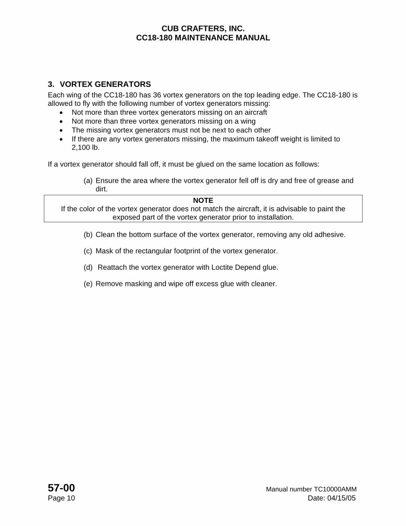
CUB CRAFTERS, INC. CC18-180 MAINTENANCE MANUAL
57-00 Manual number TC10000AMM Page 10 Date: 04/15/05
3. VORTEX GENERATORS Each wing of the CC18-180 has 36 vortex generators on the top leading edge. The CC18-180 is allowed to fly with the following number of vortex generators missing:
Not more than three vortex generators missing on an aircraft Not more than three vortex generators missing on a wing The missing vortex generators must not be next to each other If there are any vortex generators missing, the maximum takeoff weight is limited to
2,100 lb. If a vortex generator should fall off, it must be glued on the same location as follows:
(a) Ensure the area where the vortex generator fell off is dry and free of grease and dirt.
NOTE If the color of the vortex generator does not match the aircraft, it is advisable to paint the
exposed part of the vortex generator prior to installation.
(b) Clean the bottom surface of the vortex generator, removing any old adhesive.
(c) Mask of the rectangular footprint of the vortex generator.
(d) Reattach the vortex generator with Loctite Depend glue.
(e) Remove masking and wipe off excess glue with cleaner.
CHAPTER
60-00
PROPELLER

CUB CRAFTERS, INC. CC18-180 MAINTENANCE MANUAL
Manual number TC10000AMM 60-00 Date: 07/18/12 Page: 1
60-00 PROPELLER TABLE OF CONTENTS 1. GENERAL ......................................................................................................................... 2
2. METAL PROPELLERS ..................................................................................................... 2
A. TROUBLESHOOTING .................................................................................................. 2
B. MAINTENANCE PRACTICES ....................................................................................... 3
(1) REMOVAL ..................................................................................................................... 3
(2) INSPECTION ................................................................................................................ 3
(3) INSTALLATION ............................................................................................................. 3
3. WOOD PROPELLER ........................................................................................................ 4
A. TROUBLESHOOTING .................................................................................................. 4
B. MAINTENANCE PRACTICES ....................................................................................... 4
(1) PROPELLER MAINTENANCE (BOLT TORQUE) ........................................................ 4
(2) BOLT TORQUE CHECK PROCEDURE ....................................................................... 5
C. SERVICING ................................................................................................................... 6
(1) REMOVAL ..................................................................................................................... 6
(2) INSPECTION ................................................................................................................ 7
(3) HUB INSPECTION ........................................................................................................ 7
(4) INSTALLATION ............................................................................................................. 8
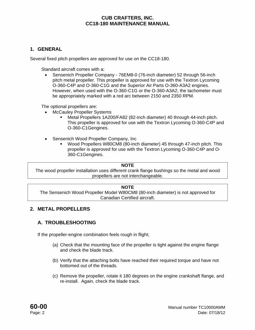
CUB CRAFTERS, INC. CC18-180 MAINTENANCE MANUAL
60-00 Manual number TC10000AMM Page: 2 Date: 07/18/12
1. GENERAL
Several fixed pitch propellers are approved for use on the CC18-180.
Standard aircraft comes with a: Sensenich Propeller Company - 76EM8-0 (76-inch diameter) 52 through 56-inch
pitch metal propeller. This propeller is approved for use with the Textron Lycoming O-360-C4P and O-360-C1G and the Superior Air Parts O-360-A3A2 engines. However, when used with the O-360-C1G or the O-360-A3A2, the tachometer must be appropriately marked with a red arc between 2150 and 2350 RPM.
The optional propellers are: McCauley Propeller Systems
Metal Propellers 1A200/FA82 (82-inch diameter) 40 through 44-inch pitch. This propeller is approved for use with the Textron Lycoming O-360-C4P and O-360-C1Gengines.
Sensenich Wood Propeller Company, Inc
Wood Propellers W80CM8 (80-inch diameter) 45 through 47-inch pitch. This propeller is approved for use with the Textron Lycoming O-360-C4P and O-360-C1Gengines.
NOTE
The wood propeller installation uses different crank flange bushings so the metal and wood propellers are not interchangeable.
NOTE
The Sensenich Wood Propeller Model W80CM8 (80-inch diameter) is not approved for Canadian Certified aircraft.
2. METAL PROPELLERS
A. TROUBLESHOOTING
If the propeller-engine combination feels rough in flight;
(a) Check that the mounting face of the propeller is tight against the engine flange and check the blade track.
(b) Verify that the attaching bolts have reached their required torque and have not bottomed out of the threads.
(c) Remove the propeller, rotate it 180 degrees on the engine crankshaft flange, and re-install. Again, check the blade track.
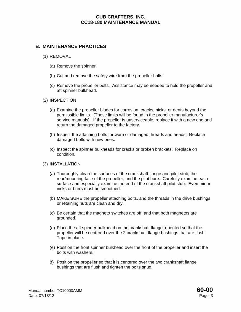
CUB CRAFTERS, INC. CC18-180 MAINTENANCE MANUAL
Manual number TC10000AMM 60-00 Date: 07/18/12 Page: 3
B. MAINTENANCE PRACTICES
(1) REMOVAL
(a) Remove the spinner.
(b) Cut and remove the safety wire from the propeller bolts.
(c) Remove the propeller bolts. Assistance may be needed to hold the propeller and aft spinner bulkhead.
(2) INSPECTION
(a) Examine the propeller blades for corrosion, cracks, nicks, or dents beyond the permissible limits. (These limits will be found in the propeller manufacturer’s service manuals). If the propeller is unserviceable, replace it with a new one and return the damaged propeller to the factory.
(b) Inspect the attaching bolts for worn or damaged threads and heads. Replace damaged bolts with new ones.
(c) Inspect the spinner bulkheads for cracks or broken brackets. Replace on condition.
(3) INSTALLATION
(a) Thoroughly clean the surfaces of the crankshaft flange and pilot stub, the rear/mounting face of the propeller, and the pilot bore. Carefully examine each surface and especially examine the end of the crankshaft pilot stub. Even minor nicks or burrs must be smoothed.
(b) MAKE SURE the propeller attaching bolts, and the threads in the drive bushings or retaining nuts are clean and dry.
(c) Be certain that the magneto switches are off, and that both magnetos are grounded.
(d) Place the aft spinner bulkhead on the crankshaft flange, oriented so that the propeller will be centered over the 2 crankshaft flange bushings that are flush. Tape in place.
(e) Position the front spinner bulkhead over the front of the propeller and insert the bolts with washers.
(f) Position the propeller so that it is centered over the two crankshaft flange bushings that are flush and tighten the bolts snug.
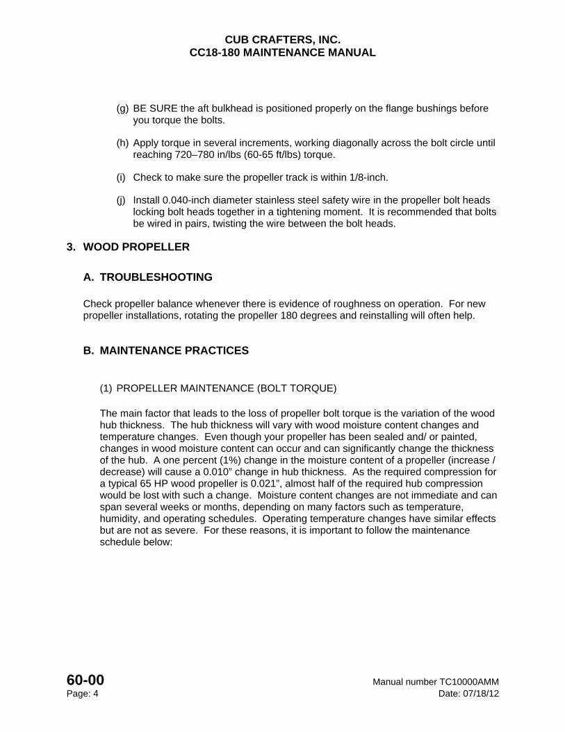
CUB CRAFTERS, INC. CC18-180 MAINTENANCE MANUAL
60-00 Manual number TC10000AMM Page: 4 Date: 07/18/12
(g) BE SURE the aft bulkhead is positioned properly on the flange bushings before you torque the bolts.
(h) Apply torque in several increments, working diagonally across the bolt circle until reaching 720–780 in/lbs (60-65 ft/lbs) torque.
(i) Check to make sure the propeller track is within 1/8-inch.
(j) Install 0.040-inch diameter stainless steel safety wire in the propeller bolt heads locking bolt heads together in a tightening moment. It is recommended that bolts be wired in pairs, twisting the wire between the bolt heads.
3. WOOD PROPELLER
A. TROUBLESHOOTING
Check propeller balance whenever there is evidence of roughness on operation. For new propeller installations, rotating the propeller 180 degrees and reinstalling will often help.
B. MAINTENANCE PRACTICES
(1) PROPELLER MAINTENANCE (BOLT TORQUE)
The main factor that leads to the loss of propeller bolt torque is the variation of the wood hub thickness. The hub thickness will vary with wood moisture content changes and temperature changes. Even though your propeller has been sealed and/ or painted, changes in wood moisture content can occur and can significantly change the thickness of the hub. A one percent (1%) change in the moisture content of a propeller (increase / decrease) will cause a 0.010” change in hub thickness. As the required compression for a typical 65 HP wood propeller is 0.021”, almost half of the required hub compression would be lost with such a change. Moisture content changes are not immediate and can span several weeks or months, depending on many factors such as temperature, humidity, and operating schedules. Operating temperature changes have similar effects but are not as severe. For these reasons, it is important to follow the maintenance schedule below:
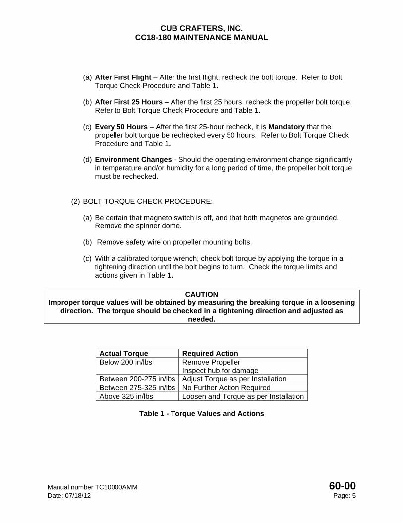
CUB CRAFTERS, INC. CC18-180 MAINTENANCE MANUAL
Manual number TC10000AMM 60-00 Date: 07/18/12 Page: 5
(a) After First Flight – After the first flight, recheck the bolt torque. Refer to Bolt Torque Check Procedure and Table 1.
(b) After First 25 Hours – After the first 25 hours, recheck the propeller bolt torque. Refer to Bolt Torque Check Procedure and Table 1.
(c) Every 50 Hours – After the first 25-hour recheck, it is Mandatory that the propeller bolt torque be rechecked every 50 hours. Refer to Bolt Torque Check Procedure and Table 1.
(d) Environment Changes - Should the operating environment change significantly in temperature and/or humidity for a long period of time, the propeller bolt torque must be rechecked.
(2) BOLT TORQUE CHECK PROCEDURE:
(a) Be certain that magneto switch is off, and that both magnetos are grounded. Remove the spinner dome.
(b) Remove safety wire on propeller mounting bolts.
(c) With a calibrated torque wrench, check bolt torque by applying the torque in a tightening direction until the bolt begins to turn. Check the torque limits and actions given in Table 1.
CAUTION
Improper torque values will be obtained by measuring the breaking torque in a loosening direction. The torque should be checked in a tightening direction and adjusted as
needed.
Actual Torque Required Action Below 200 in/lbs Remove Propeller
Inspect hub for damage Between 200-275 in/lbs Adjust Torque as per Installation Between 275-325 in/lbs No Further Action Required Above 325 in/lbs Loosen and Torque as per Installation
Table 1 - Torque Values and Actions
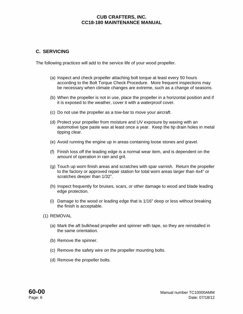
CUB CRAFTERS, INC. CC18-180 MAINTENANCE MANUAL
60-00 Manual number TC10000AMM Page: 6 Date: 07/18/12
C. SERVICING
The following practices will add to the service life of your wood propeller.
(a) Inspect and check propeller attaching bolt torque at least every 50 hours according to the Bolt Torque Check Procedure. More frequent inspections may be necessary when climate changes are extreme, such as a change of seasons.
(b) When the propeller is not in use, place the propeller in a horizontal position and if it is exposed to the weather, cover it with a waterproof cover.
(c) Do not use the propeller as a tow-bar to move your aircraft.
(d) Protect your propeller from moisture and UV exposure by waxing with an automotive type paste wax at least once a year. Keep the tip drain holes in metal tipping clear.
(e) Avoid running the engine up in areas containing loose stones and gravel.
(f) Finish loss off the leading edge is a normal wear item, and is dependent on the amount of operation in rain and grit.
(g) Touch up worn finish areas and scratches with spar varnish. Return the propeller to the factory or approved repair station for total worn areas larger than 4x4” or scratches deeper than 1/32”.
(h) Inspect frequently for bruises, scars, or other damage to wood and blade leading edge protection.
(i) Damage to the wood or leading edge that is 1/16” deep or less without breaking the finish is acceptable.
(1) REMOVAL
(a) Mark the aft bulkhead propeller and spinner with tape, so they are reinstalled in the same orientation.
(b) Remove the spinner.
(c) Remove the safety wire on the propeller mounting bolts.
(d) Remove the propeller bolts.
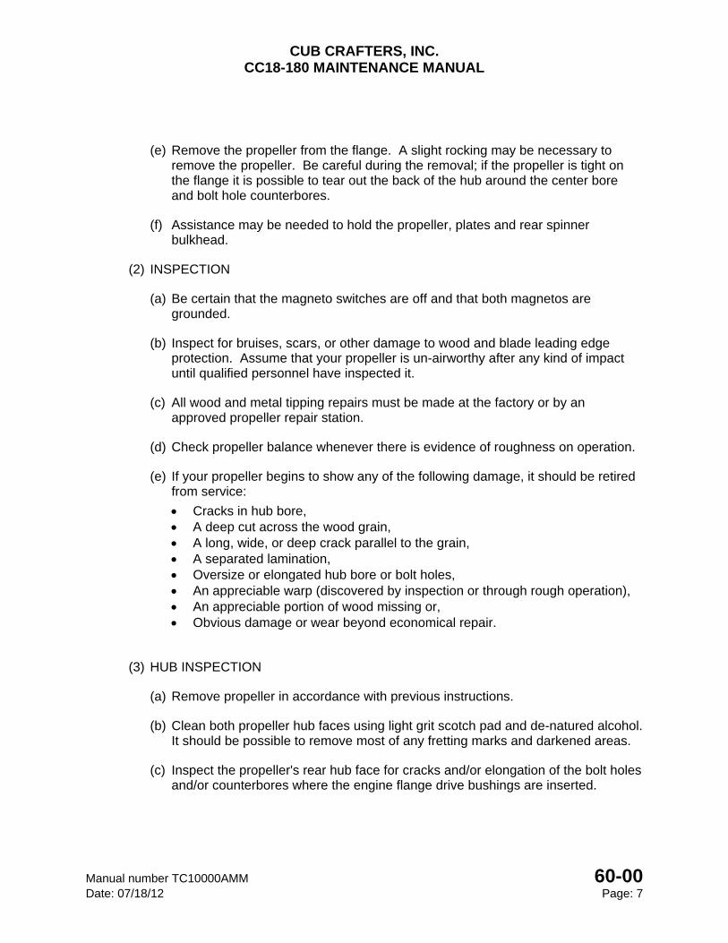
CUB CRAFTERS, INC. CC18-180 MAINTENANCE MANUAL
Manual number TC10000AMM 60-00 Date: 07/18/12 Page: 7
(e) Remove the propeller from the flange. A slight rocking may be necessary to remove the propeller. Be careful during the removal; if the propeller is tight on the flange it is possible to tear out the back of the hub around the center bore and bolt hole counterbores.
(f) Assistance may be needed to hold the propeller, plates and rear spinner bulkhead.
(2) INSPECTION
(a) Be certain that the magneto switches are off and that both magnetos are grounded.
(b) Inspect for bruises, scars, or other damage to wood and blade leading edge protection. Assume that your propeller is un-airworthy after any kind of impact until qualified personnel have inspected it.
(c) All wood and metal tipping repairs must be made at the factory or by an approved propeller repair station.
(d) Check propeller balance whenever there is evidence of roughness on operation.
(e) If your propeller begins to show any of the following damage, it should be retired from service:
Cracks in hub bore, A deep cut across the wood grain, A long, wide, or deep crack parallel to the grain, A separated lamination, Oversize or elongated hub bore or bolt holes, An appreciable warp (discovered by inspection or through rough operation), An appreciable portion of wood missing or, Obvious damage or wear beyond economical repair.
(3) HUB INSPECTION
(a) Remove propeller in accordance with previous instructions.
(b) Clean both propeller hub faces using light grit scotch pad and de-natured alcohol. It should be possible to remove most of any fretting marks and darkened areas.
(c) Inspect the propeller's rear hub face for cracks and/or elongation of the bolt holes and/or counterbores where the engine flange drive bushings are inserted.
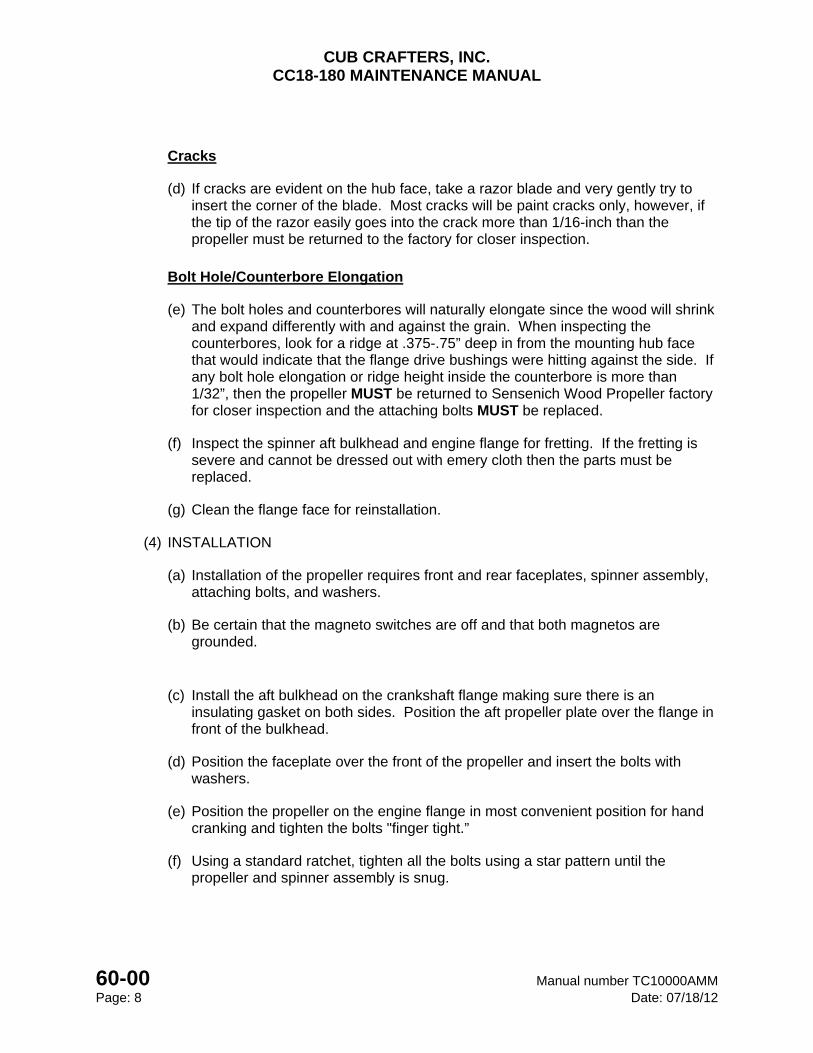
CUB CRAFTERS, INC. CC18-180 MAINTENANCE MANUAL
60-00 Manual number TC10000AMM Page: 8 Date: 07/18/12
Cracks
(d) If cracks are evident on the hub face, take a razor blade and very gently try to insert the corner of the blade. Most cracks will be paint cracks only, however, if the tip of the razor easily goes into the crack more than 1/16-inch than the propeller must be returned to the factory for closer inspection.
Bolt Hole/Counterbore Elongation
(e) The bolt holes and counterbores will naturally elongate since the wood will shrink and expand differently with and against the grain. When inspecting the counterbores, look for a ridge at .375-.75” deep in from the mounting hub face that would indicate that the flange drive bushings were hitting against the side. If any bolt hole elongation or ridge height inside the counterbore is more than 1/32”, then the propeller MUST be returned to Sensenich Wood Propeller factory for closer inspection and the attaching bolts MUST be replaced.
(f) Inspect the spinner aft bulkhead and engine flange for fretting. If the fretting is severe and cannot be dressed out with emery cloth then the parts must be replaced.
(g) Clean the flange face for reinstallation.
(4) INSTALLATION
(a) Installation of the propeller requires front and rear faceplates, spinner assembly, attaching bolts, and washers.
(b) Be certain that the magneto switches are off and that both magnetos are grounded.
(c) Install the aft bulkhead on the crankshaft flange making sure there is an insulating gasket on both sides. Position the aft propeller plate over the flange in front of the bulkhead.
(d) Position the faceplate over the front of the propeller and insert the bolts with washers.
(e) Position the propeller on the engine flange in most convenient position for hand cranking and tighten the bolts "finger tight.”
(f) Using a standard ratchet, tighten all the bolts using a star pattern until the propeller and spinner assembly is snug.
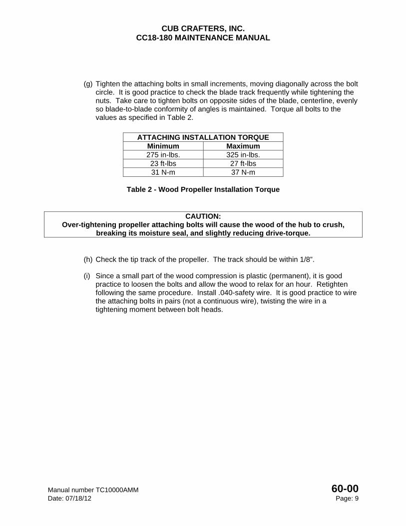
CUB CRAFTERS, INC. CC18-180 MAINTENANCE MANUAL
Manual number TC10000AMM 60-00 Date: 07/18/12 Page: 9
(g) Tighten the attaching bolts in small increments, moving diagonally across the bolt circle. It is good practice to check the blade track frequently while tightening the nuts. Take care to tighten bolts on opposite sides of the blade, centerline, evenly so blade-to-blade conformity of angles is maintained. Torque all bolts to the values as specified in Table 2.
ATTACHING INSTALLATION TORQUE
Minimum Maximum 275 in-lbs. 325 in-lbs. 23 ft-lbs 27 ft-lbs 31 N-m 37 N-m
Table 2 - Wood Propeller Installation Torque
CAUTION: Over-tightening propeller attaching bolts will cause the wood of the hub to crush,
breaking its moisture seal, and slightly reducing drive-torque.
(h) Check the tip track of the propeller. The track should be within 1/8”.
(i) Since a small part of the wood compression is plastic (permanent), it is good practice to loosen the bolts and allow the wood to relax for an hour. Retighten following the same procedure. Install .040-safety wire. It is good practice to wire the attaching bolts in pairs (not a continuous wire), twisting the wire in a tightening moment between bolt heads.
CUB CRAFTERS, INC. CC18-180 MAINTENANCE MANUAL
60-00 Manual number TC10000AMM Page: 10 Date: 07/18/12
INTENTIONALLY LEFT BLANK

CHAPTER
71
POWERPLANT

CUB CRAFTERS, INC. CC18-180 MAINTENANCE MANUAL
Manual number TC10000AMM 71 Date: 7/18/12 Page: i
71 POWERPLANT
71-00 ...................................................................................................................... POWERPLANT
71-10 ..................................................................................................................... ENGINE COWL
71-60 .................................................................................................................... AIR INDUCTION
CUB CRAFTERS, INC. CC18-180 MAINTENANCE MANUAL
71 Manual number TC10000AMM Page: ii Date: 7/18/12
INTENTIONALLY LEFT BLANK
CUB CRAFTERS, INC. CC18-180 MAINTENANCE MANUAL
Manual number TC10000AMM 71-00 Date: 7/18/12 Page: 1
71-00 POWERPLANT TABLE OF CONTENTS 1. GENERAL .............................................................................................................................. 2
2. TROUBLESHOOTING ........................................................................................................... 3
CUB CRAFTERS, INC. CC18-180 MAINTENANCE MANUAL
71-00 Manual number TC10000AMM Page: 2 Date: 7/18/12
1. GENERAL
This chapter describes maintenance practices for the airplane’s powerplant. The CC18-180 is powered by one of the following engines:
1. a Textron Lycoming O-360-C4P engine. This is an air-cooled, four cylinder, direct drive, horizontally opposed engine that is capable of delivering up to 180 hp at 2700 RPM
2. a Textron Lycoming O-360-C1G engine. This is an air-cooled, four cylinder, direct drive, horizontally opposed engine containing a hollow crankshaft for use with constant speed propeller systems capable of delivering up to 180 hp at 2700 RPM.
3. Superior Air Parts O-360-A3A3 engine This is an air-cooled, four cylinder, direct drive, horizontally opposed engine containing a hollow crankshaft for use with constant speed propeller systems capable of delivering up to 180 hp at 2700 RPM.
The engine is mounted to the fuselage with a tubular truss made of 4130N steel that is bolted to the airframe in four places. The engine is attached to the mount through rubber mounts to reduce vibration.
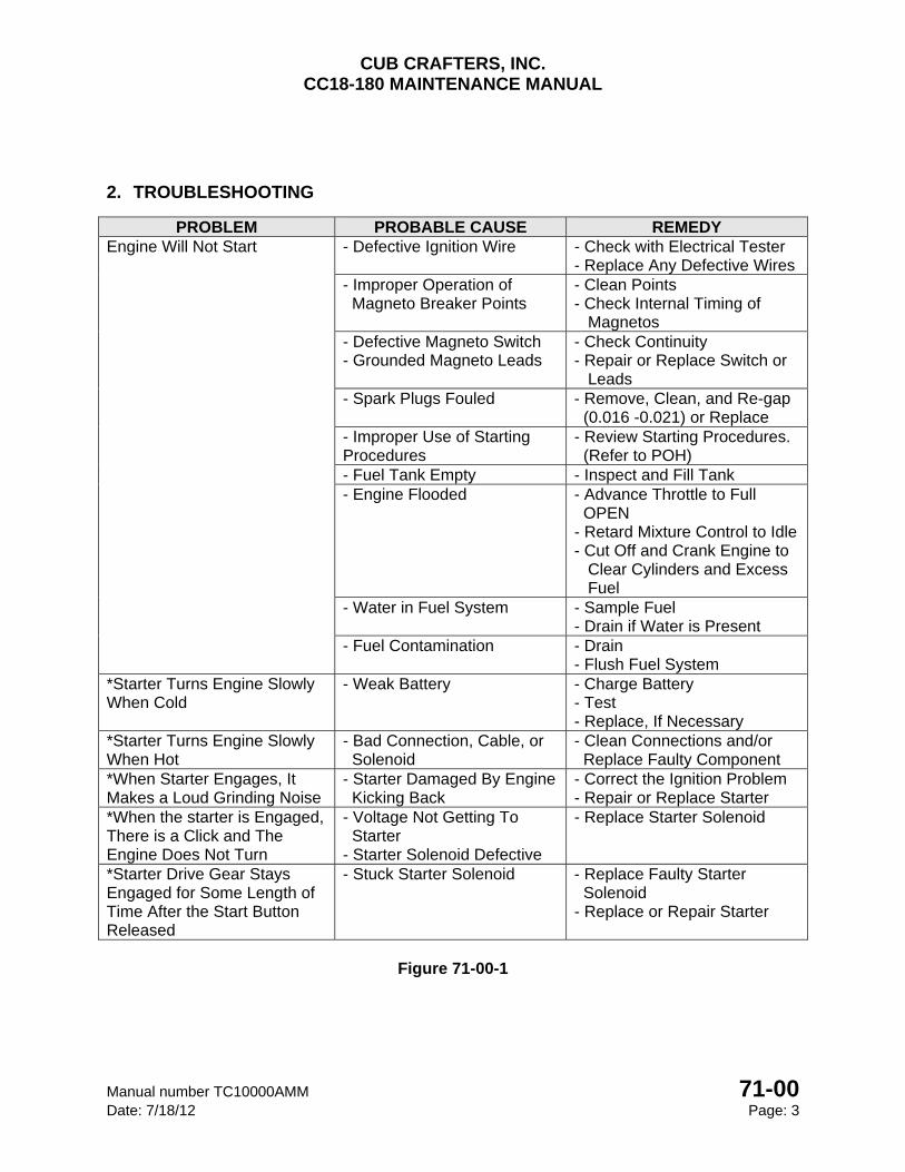
CUB CRAFTERS, INC. CC18-180 MAINTENANCE MANUAL
Manual number TC10000AMM 71-00 Date: 7/18/12 Page: 3
2. TROUBLESHOOTING
PROBLEM PROBABLE CAUSE REMEDY Engine Will Not Start - Defective Ignition Wire - Check with Electrical Tester
- Replace Any Defective Wires - Improper Operation of Magneto Breaker Points
- Clean Points - Check Internal Timing of Magnetos
- Defective Magneto Switch - Grounded Magneto Leads
- Check Continuity - Repair or Replace Switch or Leads
- Spark Plugs Fouled - Remove, Clean, and Re-gap (0.016 -0.021) or Replace
- Improper Use of Starting Procedures
- Review Starting Procedures. (Refer to POH)
- Fuel Tank Empty - Inspect and Fill Tank - Engine Flooded - Advance Throttle to Full
OPEN - Retard Mixture Control to Idle - Cut Off and Crank Engine to Clear Cylinders and Excess Fuel
- Water in Fuel System - Sample Fuel - Drain if Water is Present
- Fuel Contamination - Drain - Flush Fuel System
*Starter Turns Engine Slowly When Cold
- Weak Battery - Charge Battery - Test - Replace, If Necessary
*Starter Turns Engine Slowly When Hot
- Bad Connection, Cable, or Solenoid
- Clean Connections and/or Replace Faulty Component
*When Starter Engages, It Makes a Loud Grinding Noise
- Starter Damaged By Engine Kicking Back
- Correct the Ignition Problem - Repair or Replace Starter
*When the starter is Engaged, There is a Click and The Engine Does Not Turn
- Voltage Not Getting To Starter - Starter Solenoid Defective
- Replace Starter Solenoid
*Starter Drive Gear Stays Engaged for Some Length of Time After the Start Button Released
- Stuck Starter Solenoid - Replace Faulty Starter Solenoid - Replace or Repair Starter
Figure 71-00-1
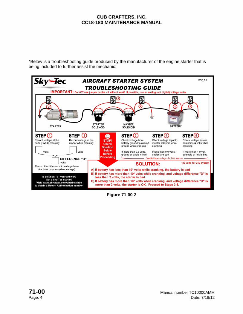
CUB CRAFTERS, INC. CC18-180 MAINTENANCE MANUAL
71-00 Manual number TC10000AMM Page: 4 Date: 7/18/12
*Below is a troubleshooting guide produced by the manufacturer of the engine starter that is being included to further assist the mechanic:
Figure 71-00-2
CUB CRAFTERS, INC. CC18-180 MAINTENANCE MANUAL
Manual number TC10000AMM 71-10 Date: 12/29/14 Page: 1
71-10 ENGINE COWL
TABLE OF CONTENTS 1 GENERAL ............................................................................................................................. 2 1.1 ENGINE COWL ..................................................................................................................... 2
1.1.1 REMOVAL ............................................................................................................... 2 1.1.2 INSPECTION .......................................................................................................... 2 1.1.3 INSTALLATION ....................................................................................................... 3
1.2 WINTERIZATION KIT ............................................................................................................ 4 1.2.1 INSTALLATION .......................................................................................................... 4
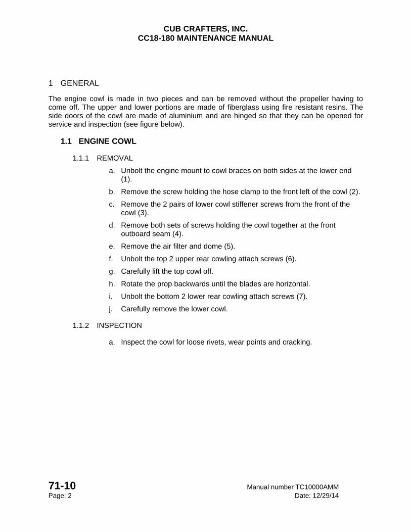
CUB CRAFTERS, INC. CC18-180 MAINTENANCE MANUAL
71-10 Manual number TC10000AMM Page: 2 Date: 12/29/14
1 GENERAL
The engine cowl is made in two pieces and can be removed without the propeller having to come off. The upper and lower portions are made of fiberglass using fire resistant resins. The side doors of the cowl are made of aluminium and are hinged so that they can be opened for service and inspection (see figure below).
1.1 ENGINE COWL
1.1.1 REMOVAL
a. Unbolt the engine mount to cowl braces on both sides at the lower end (1).
b. Remove the screw holding the hose clamp to the front left of the cowl (2).
c. Remove the 2 pairs of lower cowl stiffener screws from the front of the cowl (3).
d. Remove both sets of screws holding the cowl together at the front outboard seam (4).
e. Remove the air filter and dome (5).
f. Unbolt the top 2 upper rear cowling attach screws (6).
g. Carefully lift the top cowl off.
h. Rotate the prop backwards until the blades are horizontal.
i. Unbolt the bottom 2 lower rear cowling attach screws (7).
j. Carefully remove the lower cowl.
1.1.2 INSPECTION
a. Inspect the cowl for loose rivets, wear points and cracking.
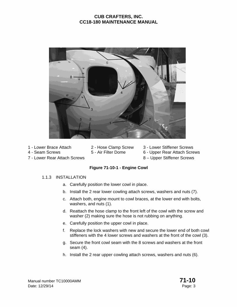
CUB CRAFTERS, INC. CC18-180 MAINTENANCE MANUAL
Manual number TC10000AMM 71-10 Date: 12/29/14 Page: 3
1 - Lower Brace Attach 2 - Hose Clamp Screw 3 - Lower Stiffener Screws 4 - Seam Screws 5 - Air Filter Dome 6 - Upper Rear Attach Screws 7 - Lower Rear Attach Screws 8 – Upper Stiffener Screws
Figure 71-10-1 - Engine Cowl
1.1.3 INSTALLATION
a. Carefully position the lower cowl in place.
b. Install the 2 rear lower cowling attach screws, washers and nuts (7).
c. Attach both, engine mount to cowl braces, at the lower end with bolts, washers, and nuts (1).
d. Reattach the hose clamp to the front left of the cowl with the screw and washer (2) making sure the hose is not rubbing on anything.
e. Carefully position the upper cowl in place.
f. Replace the lock washers with new and secure the lower end of both cowl stiffeners with the 4 lower screws and washers at the front of the cowl (3).
g. Secure the front cowl seam with the 8 screws and washers at the front seam (4).
h. Install the 2 rear upper cowling attach screws, washers and nuts (6).
CUB CRAFTERS, INC. CC18-180 MAINTENANCE MANUAL
71-10 Manual number TC10000AMM Page: 4 Date: 12/29/14
i. Install the air filter and dome (5) (Refer to 71-60 2.A.)
j. Double check to make sure all the hardware is tight.
k. Makes sure the felt baffle seal is laying properly.
l. Verify that there is equal clearance from the cowl on each side of the ring gear and that the stiffeners are properly installed and not rubbing (8).
1.2 WINTERIZATION KIT
1.2.1 INSTALLATION
CAUTION
This kit must be removed when the aircraft is operated above 40°F.
Service Letter SL0003 must be complied with prior to this installation.
a. Remove the top engine cowl, and remove the four bolts and hardware attaching the oil cooler to the engine baffles in accordance with the instructions in Section 1.1.1.
b. Remove attachment bolts and support oil cooler. Do not disconnect oil lines.
c. Install oil cooler plate (TC5021-001) in front of baffle, aligned with the four bolt holes and oriented with the flat edge down. This should leave the opening at the top. Reinstall the oil cooler and securely fasten with previous hardware.
d. Verify that 1.00”±.13 of the oil cooler is still exposed. Trim plate as needed to achieve this.
e. As required, install anti-chafe tape onto the exterior of the cowling to prevent plate from rubbing.
f. Install SCAT Tube Flange (101889-01) on forward left baffle with screws (AN526C632R7), washers (AN960-6L) and lock nuts (AN363-632).
g. Install the cowl plates with (AN526C632R6), ensuring the flat side of the cowl plates faces forward and the flange is at the top.
h. Install SCAT tube (RM0006-001) between left cowl plate and flange on baffle with hose clamps (AN737TW74).
i. Reinstall top engine cowl per the instructions in Section 1.1.3.
j. Verify that there is a 2.75”± .13 gap from the top of the plates to the top of the cowl inlets.
k. Removal of oil cooler plate and cowl inlet plates is done opposite of installation.
l. For subsequent operations in cold weather, repeat Steps a-h.
m. Make a logbook entry each time kit is installed or removed.
CUB CRAFTERS, INC. CC18-180 MAINTENANCE MANUAL
Manual number TC10000AMM 71-60 Date: 05/20/08 Page: 1
71-60 AIR INDUCTION SYSTEM TABLE OF CONTENTS 1. GENERAL ............................................................................................................. 2
2. MAINTENANCE PRACTICES .............................................................................. 3
A. AIR FILTER ........................................................................................................... 3
(1) REMOVAL ......................................................................................................... 3
(2) INSPECTION .................................................................................................... 4
(3) INSTALLATION ................................................................................................. 4
B. AIR BOX ................................................................................................................ 4
(1) REMOVAL ......................................................................................................... 4
(2) INSPECTION .................................................................................................... 5
C. CARBURETOR HEAT .......................................................................................... 7
(1) INSTALLATION OF CABLE TO AIRBOX ARM SWIVEL FITTING ................... 7
(2) CABLE CLAMP ................................................................................................. 8
(3) INSPECTION .................................................................................................... 8
CUB CRAFTERS, INC. CC18-180 MAINTENANCE MANUAL
71-60 Manual number TC10000AMM Page: 2 Date: 05/20/08
1. GENERAL
The induction air for the engine enters through a filter on the lower side of the cowling and from there the air goes through an air box into the carburetor. The carburetor heat control operates a butterfly valve that allows heated, unfiltered air to feed into the engine. The carburetor heat control is located on the top left side of the instrument panel.
CAUTION Ground operations with the carburetor heat control in the hot position
must be limited because it allows air to bypass the filter. Should the air filter become obstructed, the carburetor air control provides an alternate manual means of supplying the engine with air for the induction system.
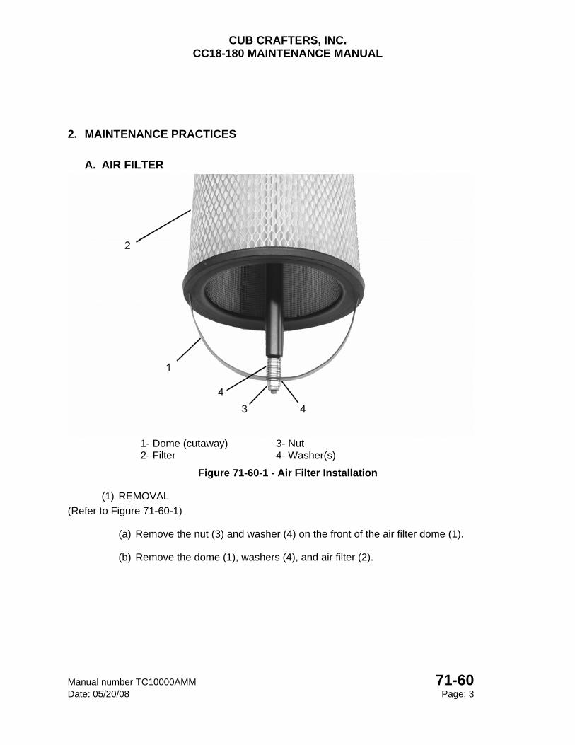
CUB CRAFTERS, INC. CC18-180 MAINTENANCE MANUAL
Manual number TC10000AMM 71-60 Date: 05/20/08 Page: 3
2. MAINTENANCE PRACTICES
A. AIR FILTER
1- Dome (cutaway) 3- Nut 2- Filter 4- Washer(s)
Figure 71-60-1 - Air Filter Installation
(1) REMOVAL
(Refer to Figure 71-60-1)
(a) Remove the nut (3) and washer (4) on the front of the air filter dome (1).
(b) Remove the dome (1), washers (4), and air filter (2).
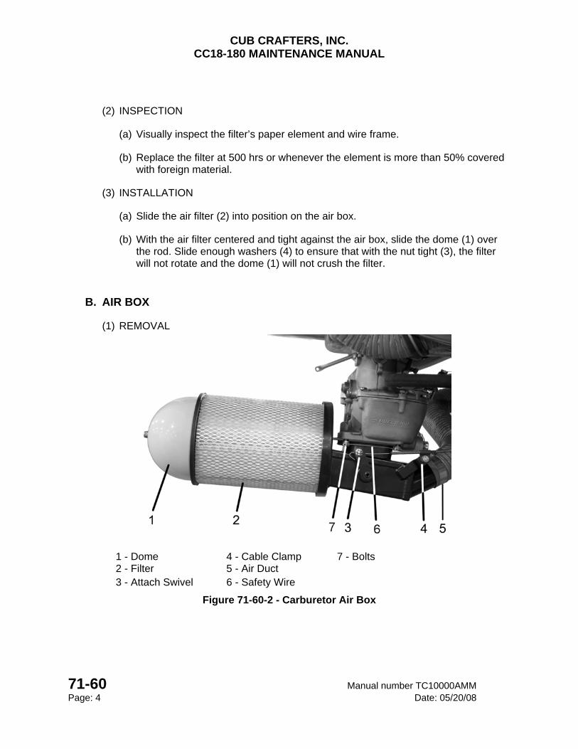
CUB CRAFTERS, INC. CC18-180 MAINTENANCE MANUAL
71-60 Manual number TC10000AMM Page: 4 Date: 05/20/08
(2) INSPECTION
(a) Visually inspect the filter’s paper element and wire frame.
(b) Replace the filter at 500 hrs or whenever the element is more than 50% covered with foreign material.
(3) INSTALLATION
(a) Slide the air filter (2) into position on the air box.
(b) With the air filter centered and tight against the air box, slide the dome (1) over the rod. Slide enough washers (4) to ensure that with the nut tight (3), the filter will not rotate and the dome (1) will not crush the filter.
B. AIR BOX
(1) REMOVAL
1 - Dome 4 - Cable Clamp 7 - Bolts 2 - Filter 5 - Air Duct 3 - Attach Swivel 6 - Safety Wire
Figure 71-60-2 - Carburetor Air Box
CUB CRAFTERS, INC. CC18-180 MAINTENANCE MANUAL
Manual number TC10000AMM 71-60 Date: 05/20/08 Page: 5
(a) Remove the air filter (2) (Refer to 71-60-2A(1)).
(b) Remove the lower cowl (Refer to 71-10).
(c) Disconnect the carburetor heat air duct (5).
(d) Mark the position of the carburetor heat control cable clamp (4) on the cable and disconnect the cable (4) from the air box.
(e) Disconnect the cable attachment swivel (3) from the butterfly arm.
(f) Cut the safety wire (6) that holds the bolts (7).
(g) Remove the bolts (7).
(2) INSPECTION
(a) Visually inspect the butterfly valve and shaft for security and wear. Pay close attention to the state of the welds that attach these parts.
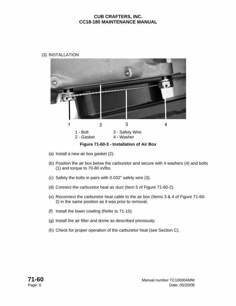
CUB CRAFTERS, INC. CC18-180 MAINTENANCE MANUAL
71-60 Manual number TC10000AMM Page: 6 Date: 05/20/08
(3) INSTALLATION
1 - Bolt 3 - Safety Wire 2 - Gasket 4 - Washer
Figure 71-60-3 - Installation of Air Box
(a) Install a new air box gasket (2).
(b) Position the air box below the carburetor and secure with 4 washers (4) and bolts (1) and torque to 70-80 in/lbs.
(c) Safety the bolts in pairs with 0.032” safety wire (3).
(d) Connect the carburetor heat air duct (Item 5 of Figure 71-60-2).
(e) Reconnect the carburetor heat cable to the air box (Items 3 & 4 of Figure 71-60-2) in the same position as it was prior to removal.
(f) Install the lower cowling (Refer to 71-10).
(g) Install the air filter and dome as described previously.
(h) Check for proper operation of the carburetor heat (see Section C).
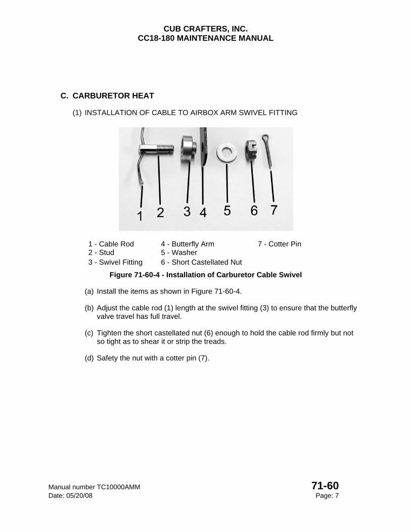
CUB CRAFTERS, INC. CC18-180 MAINTENANCE MANUAL
Manual number TC10000AMM 71-60 Date: 05/20/08 Page: 7
C. CARBURETOR HEAT
(1) INSTALLATION OF CABLE TO AIRBOX ARM SWIVEL FITTING
1 - Cable Rod 4 - Butterfly Arm 7 - Cotter Pin 2 - Stud 5 - Washer 3 - Swivel Fitting 6 - Short Castellated Nut
Figure 71-60-4 - Installation of Carburetor Cable Swivel
(a) Install the items as shown in Figure 71-60-4.
(b) Adjust the cable rod (1) length at the swivel fitting (3) to ensure that the butterfly valve travel has full travel.
(c) Tighten the short castellated nut (6) enough to hold the cable rod firmly but not so tight as to shear it or strip the treads.
(d) Safety the nut with a cotter pin (7).
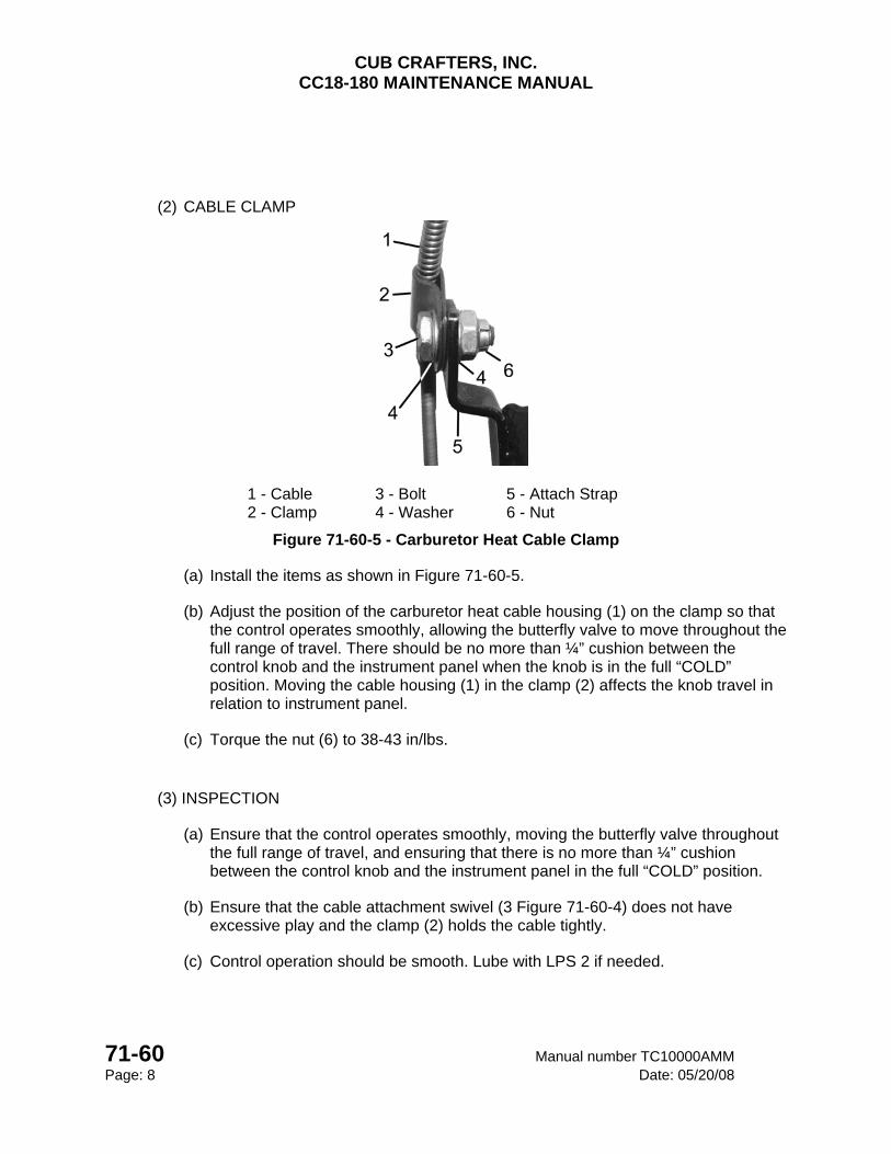
CUB CRAFTERS, INC. CC18-180 MAINTENANCE MANUAL
71-60 Manual number TC10000AMM Page: 8 Date: 05/20/08
(2) CABLE CLAMP
1 - Cable 3 - Bolt 5 - Attach Strap 2 - Clamp 4 - Washer 6 - Nut
Figure 71-60-5 - Carburetor Heat Cable Clamp
(a) Install the items as shown in Figure 71-60-5.
(b) Adjust the position of the carburetor heat cable housing (1) on the clamp so that the control operates smoothly, allowing the butterfly valve to move throughout the full range of travel. There should be no more than ¼” cushion between the control knob and the instrument panel when the knob is in the full “COLD” position. Moving the cable housing (1) in the clamp (2) affects the knob travel in relation to instrument panel.
(c) Torque the nut (6) to 38-43 in/lbs.
(3) INSPECTION
(a) Ensure that the control operates smoothly, moving the butterfly valve throughout the full range of travel, and ensuring that there is no more than ¼” cushion between the control knob and the instrument panel in the full “COLD” position.
(b) Ensure that the cable attachment swivel (3 Figure 71-60-4) does not have excessive play and the clamp (2) holds the cable tightly.
(c) Control operation should be smooth. Lube with LPS 2 if needed.

CHAPTER
74-00
IGNITION

CUB CRAFTERS, INC. CC18-180 MAINTENANCE MANUAL
Manual number TC10000AMM 74-00 Date: 05/20/08 Page: 1
74-00 IGNITION TABLE OF CONTENTS 1. GENERAL ......................................................................................................................... 2
2. MAINTENANCE PRACTICES .......................................................................................... 3
A. MAGNETOS ...................................................................................................................... 3
(1) REMOVAL ..................................................................................................................... 3
(2) INSPECTION ................................................................................................................ 4
(3) INSTALLATION ............................................................................................................. 4
B. SPARK PLUGS ................................................................................................................. 6
(1) REMOVAL ..................................................................................................................... 6
(2) INSPECTION ................................................................................................................ 6
(3) INSTALLATION ............................................................................................................. 6
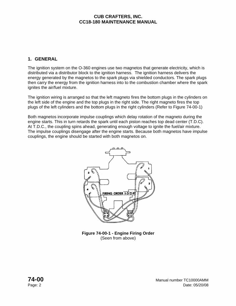
CUB CRAFTERS, INC. CC18-180 MAINTENANCE MANUAL
74-00 Manual number TC10000AMM Page: 2 Date: 05/20/08
1. GENERAL
The ignition system on the O-360 engines use two magnetos that generate electricity, which is distributed via a distributor block to the ignition harness. The ignition harness delivers the energy generated by the magnetos to the spark plugs via shielded conductors. The spark plugs then carry the energy from the ignition harness into to the combustion chamber where the spark ignites the air/fuel mixture. The ignition wiring is arranged so that the left magneto fires the bottom plugs in the cylinders on the left side of the engine and the top plugs in the right side. The right magneto fires the top plugs of the left cylinders and the bottom plugs in the right cylinders (Refer to Figure 74-00-1) Both magnetos incorporate impulse couplings which delay rotation of the magneto during the engine starts. This in turn retards the spark until each piston reaches top dead center (T.D.C). At T.D.C., the coupling spins ahead, generating enough voltage to ignite the fuel/air mixture. The impulse couplings disengage after the engine starts. Because both magnetos have impulse couplings, the engine should be started with both magnetos on.
Figure 74-00-1 - Engine Firing Order (Seen from above)
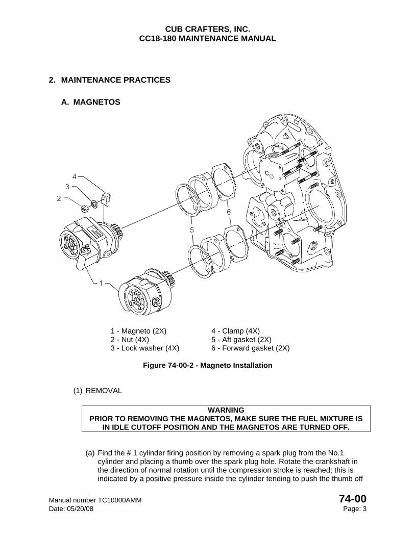
CUB CRAFTERS, INC. CC18-180 MAINTENANCE MANUAL
Manual number TC10000AMM 74-00 Date: 05/20/08 Page: 3
2. MAINTENANCE PRACTICES
A. MAGNETOS
1 - Magneto (2X) 4 - Clamp (4X) 2 - Nut (4X) 5 - Aft gasket (2X) 3 - Lock washer (4X) 6 - Forward gasket (2X)
Figure 74-00-2 - Magneto Installation
(1) REMOVAL
WARNING
PRIOR TO REMOVING THE MAGNETOS, MAKE SURE THE FUEL MIXTURE IS IN IDLE CUTOFF POSITION AND THE MAGNETOS ARE TURNED OFF.
(a) Find the # 1 cylinder firing position by removing a spark plug from the No.1 cylinder and placing a thumb over the spark plug hole. Rotate the crankshaft in the direction of normal rotation until the compression stroke is reached; this is indicated by a positive pressure inside the cylinder tending to push the thumb off
CUB CRAFTERS, INC. CC18-180 MAINTENANCE MANUAL
74-00 Manual number TC10000AMM Page: 4 Date: 05/20/08
the spark plug hole. Continue rotating the crankshaft until both impulse couplers have snapped. Line up the 25º timing mark on the front face of the starter ring gear with the alignment hole located at the two o'clock position on the front face of the starter housing (Refer to Figure 74-00-3).
(b) Unscrew the 3 harness cap screws and separate the harness from the magnetos.
(c) Disconnect the P-leads.
(d) Remove the nuts (2), washers (3) and clamps (4) that secure the magneto (1) and separate it from the engine.
(2) INSPECTION
(a) Inspect the magnetos in accordance with the current version of the Unison L-1363 maintenance manual.
(3) INSTALLATION
(a) To set the magneto’s internal timing:
Insert a T-118 timing pin in the L hole of the distributor block.
Turn the rotor shaft clockwise until the timing pin is inserted approximately 7/8” into the distributor block. When properly engaged the timing pin will “seat” against the distributor block.
NOTE
If the rotor shaft cannot be turned and the timing pin is not seated 7/8” into the distributor block, remove the pin and turn the rotor shaft 1/8 turn and reinsert the timing pin.
With the timing pin fully inserted in the distributor block, the magneto is aligned to fire cylinder #1.
CAUTION
Do not rotate the magneto rotor shaft or propeller with the timing pin fully inserted into the magneto distributor block! Rotation of the magneto shaft or propeller may damage
the internal components of the magneto and render the unit non-airworthy.
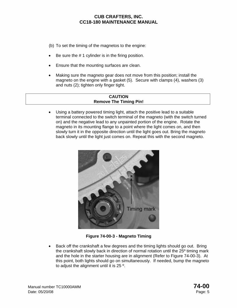
CUB CRAFTERS, INC. CC18-180 MAINTENANCE MANUAL
Manual number TC10000AMM 74-00 Date: 05/20/08 Page: 5
(b) To set the timing of the magnetos to the engine:
Be sure the # 1 cylinder is in the firing position.
Ensure that the mounting surfaces are clean.
Making sure the magneto gear does not move from this position; install the magneto on the engine with a gasket (5). Secure with clamps (4), washers (3) and nuts (2); tighten only finger tight.
CAUTION
Remove The Timing Pin!
Using a battery powered timing light, attach the positive lead to a suitable terminal connected to the switch terminal of the magneto (with the switch turned on) and the negative lead to any unpainted portion of the engine. Rotate the magneto in its mounting flange to a point where the light comes on, and then slowly turn it in the opposite direction until the light goes out. Bring the magneto back slowly until the light just comes on. Repeat this with the second magneto.
Figure 74-00-3 - Magneto Timing
Back off the crankshaft a few degrees and the timing lights should go out. Bring the crankshaft slowly back in direction of normal rotation until the 25º timing mark and the hole in the starter housing are in alignment (Refer to Figure 74-00-3). At this point, both lights should go on simultaneously. If needed, bump the magneto to adjust the alignment until it is 25 º.
CUB CRAFTERS, INC. CC18-180 MAINTENANCE MANUAL
74-00 Manual number TC10000AMM Page: 6 Date: 05/20/08
Intermediately tighten both nuts to 100 in/lbs.
Finally tighten both nuts alternately, in several steps, to 200-208 in/lbs.
Recheck the timing. If it has changed, loosen the nuts, readjust and repeat the torquing procedure.
Reconnect the P-lead ground shields with a screw to the proper magneto case. Torque to 18-20 in/lbs.
Reconnect the P-leads and tighten the nuts to 13-15 in/lbs.
Reposition the respective harness caps, insert the 3 harness cap screws and tighten to 18-20 in/lbs.
WARNING
TURN THE MAGNETO SWITCHES OFF SO THE ENGINE CANNOT ACCIDENTALLY BE STARTED.
B. SPARK PLUGS
(1) REMOVAL
(c) Unscrew all the spark plug caps.
(d) Unscrew all the spark plugs.
(2) INSPECTION
(a) Inspect the firing end of the spark plugs for any foreign material lodged between electrodes or around the insulator that could be conductive. Clean as needed.
(b) Check the electrode gap. It should be between 0.016 and 0.021 ins. Re-set if necessary.
(c) Check connector for any abnormalities and clean if needed.
(3) INSTALLATION
(a) Apply a small amount of Spark Plug Thread Lubricant (Refer to section 12-20) to the threaded area of each spark plug at the firing end. Using a new gasket, install the plugs and torque to 415-425 in/lbs.
(b) Connect the spark plug caps and torque to 80-90 in/lbs.
CHAPTER
76-00
ENGINE CONTROLS

CUB CRAFTERS, INC. CC18-180 MAINTENANCE MANUAL
Manual number TC10000AMM 76-00 Date: 05/20/08 Page: 1
76-00 ENGINE CONTROLS TABLE OF CONTENTS
1. GENERAL ............................................................................................................................. 2
2. MAINTENANCE PRACTICES .............................................................................................. 2
A. THROTTLE ........................................................................................................................ 2
(1) LEVER ATTACHMENT ................................................................................................. 2
(2) LEVER INTERCONNECT LINKAGE ............................................................................. 3
(3) ATTACHMENT OF THROTTLE CABLE TO FUSELAGE ............................................. 4
(4) MOTOR MOUNT CABLE ATTACHMENT ..................................................................... 5
(5) THROTTLE CABLE TO CARBURETOR ARM ATTACHMENT .................................... 7
(6) INSPECTION................................................................................................................. 8
B. MIXTURE ........................................................................................................................... 8
(1) MIXTURE CONTROL CABLE TO PANEL ATTACHMENT ........................................... 8
(2) MOTOR MOUNT MIXTURE CABLE ATTACHMENT ................................................... 9
(3) MIXTURE CABLE TO CARBURETOR LEVER SWIVEL ATTACHMENT .................. 10
(4) INSPECTION............................................................................................................... 11
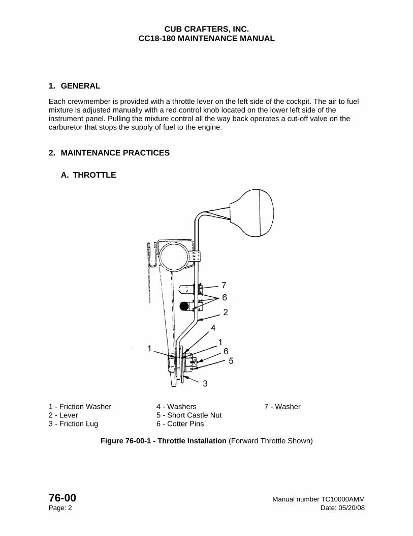
CUB CRAFTERS, INC. CC18-180 MAINTENANCE MANUAL
76-00 Manual number TC10000AMM Page: 2 Date: 05/20/08
1. GENERAL
Each crewmember is provided with a throttle lever on the left side of the cockpit. The air to fuel mixture is adjusted manually with a red control knob located on the lower left side of the instrument panel. Pulling the mixture control all the way back operates a cut-off valve on the carburetor that stops the supply of fuel to the engine.
2. MAINTENANCE PRACTICES
A. THROTTLE
1 - Friction Washer 4 - Washers 7 - Washer 2 - Lever 5 - Short Castle Nut 3 - Friction Lug 6 - Cotter Pins
Figure 76-00-1 - Throttle Installation (Forward Throttle Shown)
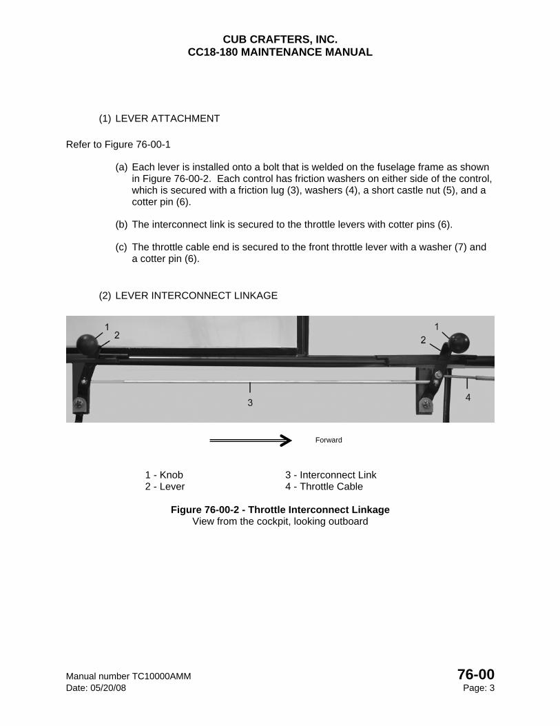
CUB CRAFTERS, INC. CC18-180 MAINTENANCE MANUAL
Manual number TC10000AMM 76-00 Date: 05/20/08 Page: 3
(1) LEVER ATTACHMENT
Refer to Figure 76-00-1
(a) Each lever is installed onto a bolt that is welded on the fuselage frame as shown in Figure 76-00-2. Each control has friction washers on either side of the control, which is secured with a friction lug (3), washers (4), a short castle nut (5), and a cotter pin (6).
(b) The interconnect link is secured to the throttle levers with cotter pins (6).
(c) The throttle cable end is secured to the front throttle lever with a washer (7) and a cotter pin (6).
(2) LEVER INTERCONNECT LINKAGE
1 - Knob 3 - Interconnect Link 2 - Lever 4 - Throttle Cable
Figure 76-00-2 - Throttle Interconnect Linkage
View from the cockpit, looking outboard
Forward
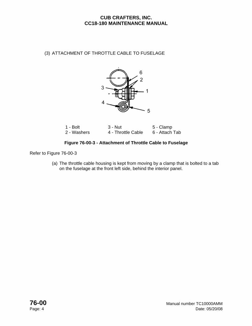
CUB CRAFTERS, INC. CC18-180 MAINTENANCE MANUAL
76-00 Manual number TC10000AMM Page: 4 Date: 05/20/08
(3) ATTACHMENT OF THROTTLE CABLE TO FUSELAGE
1 - Bolt 3 - Nut 5 - Clamp 2 - Washers 4 - Throttle Cable 6 - Attach Tab
Figure 76-00-3 - Attachment of Throttle Cable to Fuselage
Refer to Figure 76-00-3
(a) The throttle cable housing is kept from moving by a clamp that is bolted to a tab on the fuselage at the front left side, behind the interior panel.
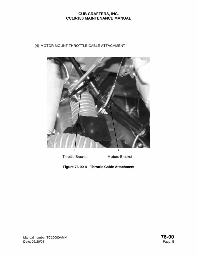
CUB CRAFTERS, INC. CC18-180 MAINTENANCE MANUAL
Manual number TC10000AMM 76-00 Date: 05/20/08 Page: 5
(4) MOTOR MOUNT THROTTLE CABLE ATTACHMENT
Figure 76-00-4 - Throttle Cable Attachment
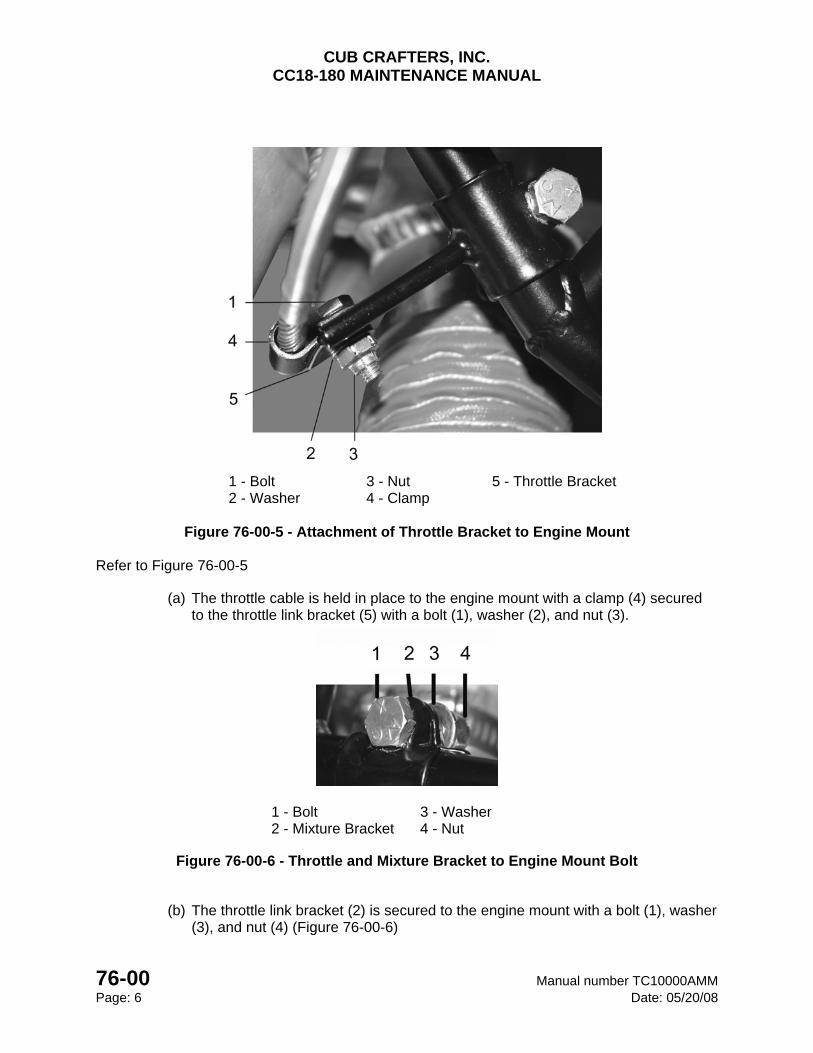
CUB CRAFTERS, INC. CC18-180 MAINTENANCE MANUAL
76-00 Manual number TC10000AMM Page: 6 Date: 05/20/08
1 - Bolt 3 - Nut 5 - Throttle Bracket 2 - Washer 4 - Clamp
Figure 76-00-5 - Attachment of Throttle Bracket to Engine Mount
Refer to Figure 76-00-5
(a) The throttle cable is held in place to the engine mount with a clamp (4) secured to the throttle link bracket (5) with a bolt (1), washer (2), and nut (3).
1 - Bolt 3 - Washer 2 - Mixture Bracket 4 - Nut
Figure 76-00-6 - Throttle and Mixture Bracket to Engine Mount Bolt
(b) The throttle link bracket (2) is secured to the engine mount with a bolt (1), washer (3), and nut (4) (Figure 76-00-6)
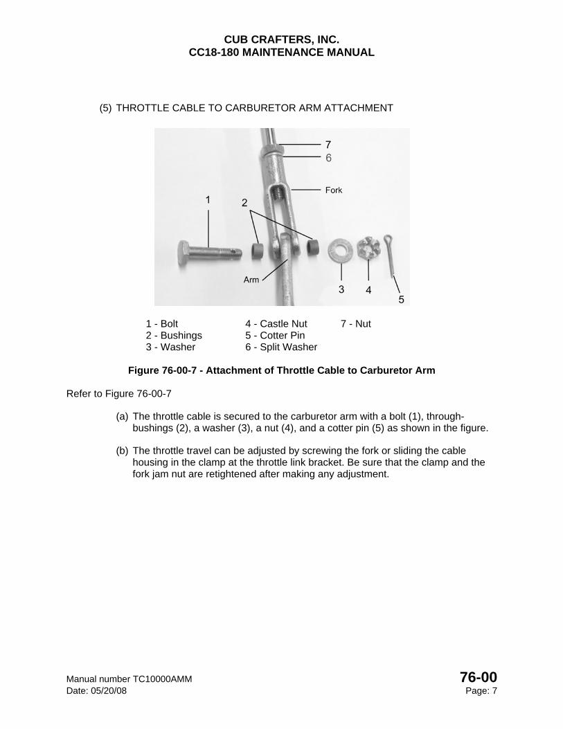
CUB CRAFTERS, INC. CC18-180 MAINTENANCE MANUAL
Manual number TC10000AMM 76-00 Date: 05/20/08 Page: 7
(5) THROTTLE CABLE TO CARBURETOR ARM ATTACHMENT
1 - Bolt 4 - Castle Nut 7 - Nut 2 - Bushings 5 - Cotter Pin 3 - Washer 6 - Split Washer
Figure 76-00-7 - Attachment of Throttle Cable to Carburetor Arm
Refer to Figure 76-00-7
(a) The throttle cable is secured to the carburetor arm with a bolt (1), through-bushings (2), a washer (3), a nut (4), and a cotter pin (5) as shown in the figure.
(b) The throttle travel can be adjusted by screwing the fork or sliding the cable housing in the clamp at the throttle link bracket. Be sure that the clamp and the fork jam nut are retightened after making any adjustment.
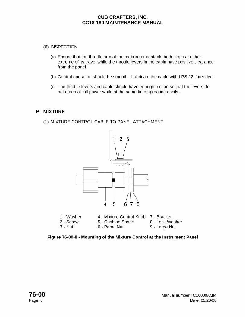
CUB CRAFTERS, INC. CC18-180 MAINTENANCE MANUAL
76-00 Manual number TC10000AMM Page: 8 Date: 05/20/08
(6) INSPECTION
(a) Ensure that the throttle arm at the carburetor contacts both stops at either extreme of its travel while the throttle levers in the cabin have positive clearance from the panel.
(b) Control operation should be smooth. Lubricate the cable with LPS #2 if needed.
(c) The throttle levers and cable should have enough friction so that the levers do not creep at full power while at the same time operating easily.
B. MIXTURE
(1) MIXTURE CONTROL CABLE TO PANEL ATTACHMENT
1 - Washer 4 - Mixture Control Knob 7 - Bracket 2 - Screw 5 - Cushion Space 8 - Lock Washer 3 - Nut 6 - Panel Nut 9 - Large Nut
Figure 76-00-8 - Mounting of the Mixture Control at the Instrument Panel
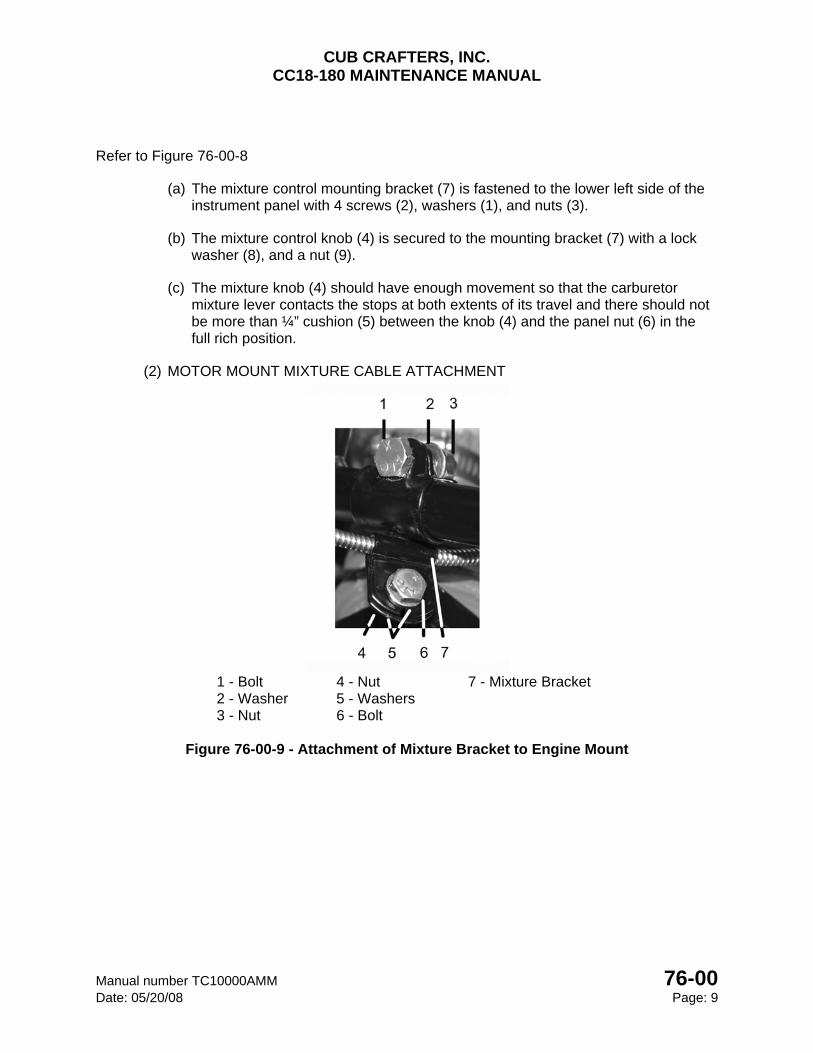
CUB CRAFTERS, INC. CC18-180 MAINTENANCE MANUAL
Manual number TC10000AMM 76-00 Date: 05/20/08 Page: 9
Refer to Figure 76-00-8
(a) The mixture control mounting bracket (7) is fastened to the lower left side of the instrument panel with 4 screws (2), washers (1), and nuts (3).
(b) The mixture control knob (4) is secured to the mounting bracket (7) with a lock washer (8), and a nut (9).
(c) The mixture knob (4) should have enough movement so that the carburetor mixture lever contacts the stops at both extents of its travel and there should not be more than ¼” cushion (5) between the knob (4) and the panel nut (6) in the full rich position.
(2) MOTOR MOUNT MIXTURE CABLE ATTACHMENT
1 - Bolt 4 - Nut 7 - Mixture Bracket 2 - Washer 5 - Washers 3 - Nut 6 - Bolt
Figure 76-00-9 - Attachment of Mixture Bracket to Engine Mount
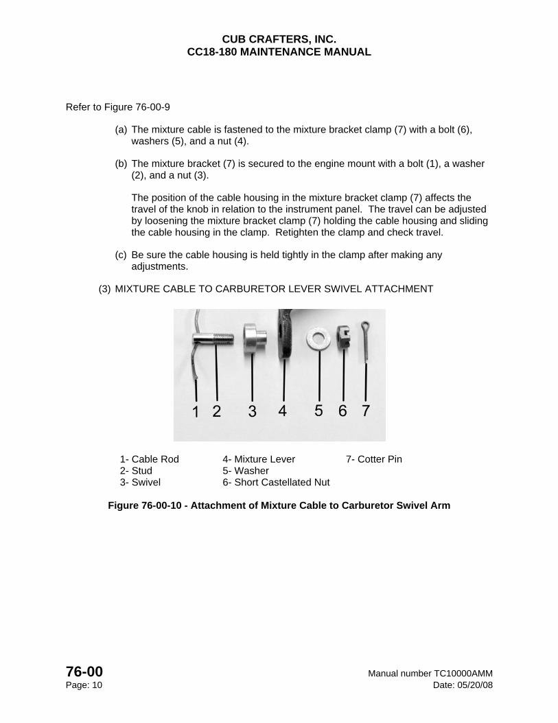
CUB CRAFTERS, INC. CC18-180 MAINTENANCE MANUAL
76-00 Manual number TC10000AMM Page: 10 Date: 05/20/08
Refer to Figure 76-00-9
(a) The mixture cable is fastened to the mixture bracket clamp (7) with a bolt (6), washers (5), and a nut (4).
(b) The mixture bracket (7) is secured to the engine mount with a bolt (1), a washer (2), and a nut (3).
The position of the cable housing in the mixture bracket clamp (7) affects the travel of the knob in relation to the instrument panel. The travel can be adjusted by loosening the mixture bracket clamp (7) holding the cable housing and sliding the cable housing in the clamp. Retighten the clamp and check travel.
(c) Be sure the cable housing is held tightly in the clamp after making any adjustments.
(3) MIXTURE CABLE TO CARBURETOR LEVER SWIVEL ATTACHMENT
1- Cable Rod 4- Mixture Lever 7- Cotter Pin 2- Stud 5- Washer 3- Swivel 6- Short Castellated Nut
Figure 76-00-10 - Attachment of Mixture Cable to Carburetor Swivel Arm
CUB CRAFTERS, INC. CC18-180 MAINTENANCE MANUAL
Manual number TC10000AMM 76-00 Date: 05/20/08 Page: 11
Refer to Figure 76-00-10
(a) The control cable rod (1) pivots the mixture control lever (4) on the carburetor. The rod (1) is held tight by the mixture swivel fitting (3).
(b) Adjusting the cable rod (1) length at the swivel fitting (3) affects the travel of the mixture control lever (4). There should be enough travel in the lever that it reaches the stops on either extreme of its travel.
(c) The swivel nut (6) should be tightened enough to hold the cable rod firmly but not enough to shear it or strip the threads.
(4) INSPECTION
(a) Ensure that the mixture lever at the carburetor contacts both stops at either extreme of its travel. At the same time, there should be no more than ¼” cushion between the knob and the panel nut in the full rich position.
(b) Inspect to be sure the cable attach swivel does not have excessive play and the cable is held tightly by the clamp.
(c) Control operation should be smooth. Lubricate with LPS #2 if required.
CUB CRAFTERS, INC. CC18-180 MAINTENANCE MANUAL
76-00 Manual number TC10000AMM Page: 12 Date: 05/20/08
INTENTIONALLY LEFT BLANK

CHAPTER
79-00
OIL SYSTEM

CUB CRAFTERS, INC. CC18-180 MAINTENANCE MANUAL
Manual number TC10000AMM 79-00 Date: 05/20/08 Page: 1
79-00 OIL SYSTEM TABLE OF CONTENTS 1. GENERAL ......................................................................................................................... 2
2. MAINTENANCE PRACTICES .......................................................................................... 2
A. OIL PRESSURE SCREEN ................................................................................................ 2
(1) REMOVAL ..................................................................................................................... 2
(2) INSPECTION ................................................................................................................ 3
(3) INSTALLATION ............................................................................................................. 3
B. OIL SUCTION SCREEN ................................................................................................... 4
(1) REMOVAL ..................................................................................................................... 4
(2) INSPECTION ................................................................................................................ 5
(3) INSTALLATION ............................................................................................................. 5
C. OIL FILTER ....................................................................................................................... 6
(1) GENERAL ..................................................................................................................... 7
(2) REMOVAL ..................................................................................................................... 8
(3) INSPECTION ................................................................................................................ 8
(4) INSTALLATION ............................................................................................................. 8
D. OIL COOLER .................................................................................................................... 9
(1) REMOVAL ................................................................................................................... 10
(2) INSTALLATION ........................................................................................................... 10
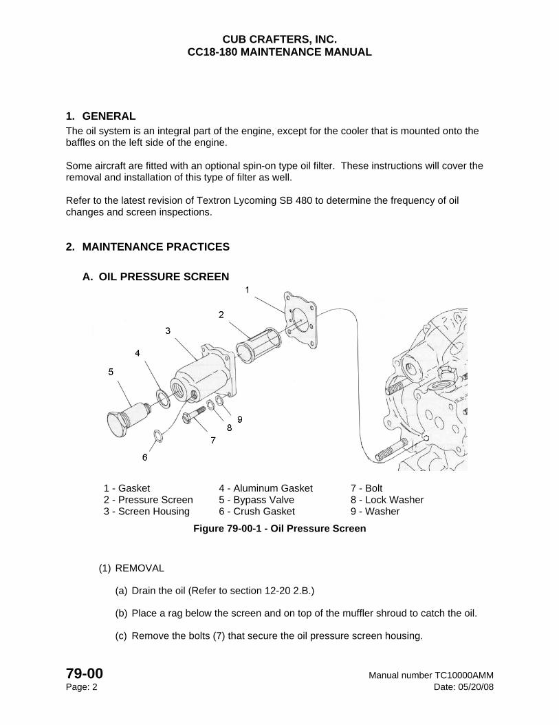
CUB CRAFTERS, INC. CC18-180 MAINTENANCE MANUAL
79-00 Manual number TC10000AMM Page: 2 Date: 05/20/08
1. GENERAL The oil system is an integral part of the engine, except for the cooler that is mounted onto the baffles on the left side of the engine. Some aircraft are fitted with an optional spin-on type oil filter. These instructions will cover the removal and installation of this type of filter as well. Refer to the latest revision of Textron Lycoming SB 480 to determine the frequency of oil changes and screen inspections.
2. MAINTENANCE PRACTICES
A. OIL PRESSURE SCREEN
1 - Gasket 4 - Aluminum Gasket 7 - Bolt 2 - Pressure Screen 5 - Bypass Valve 8 - Lock Washer 3 - Screen Housing 6 - Crush Gasket 9 - Washer
Figure 79-00-1 - Oil Pressure Screen
(1) REMOVAL
(a) Drain the oil (Refer to section 12-20 2.B.)
(b) Place a rag below the screen and on top of the muffler shroud to catch the oil.
(c) Remove the bolts (7) that secure the oil pressure screen housing.
CUB CRAFTERS, INC. CC18-180 MAINTENANCE MANUAL
Manual number TC10000AMM 79-00 Date: 05/20/08 Page: 3
CAUTION Do not damage the temperature probe wire while separating the screen housing from the
accessory case.
(d) Drain the oil from the housing and remove the screen (2).
(2) INSPECTION
(a) Inspect the screen (2) and inside the housing (3) for foreign particles.
CAUTION
If examination of the pressure screen indicates abnormal metal content, additional service may be required to determine the source and possible need for corrective
maintenance
(b) Remove the old gasket (1) and make sure the housing and case surfaces are clean.
(3) INSTALLATION
(a) Assemble the screen (2) in the housing (3), assemble the gasket (1) and the housing (3) on mounting pad.
(b) Ensure that the gasket is properly oriented.
(c) Using new lock washers (8), secure the housing with 4 bolts (7), torque to 92-100 in/lbs.
(d) Remove the rag and clean all excess oil from the engine, firewall and muffler.
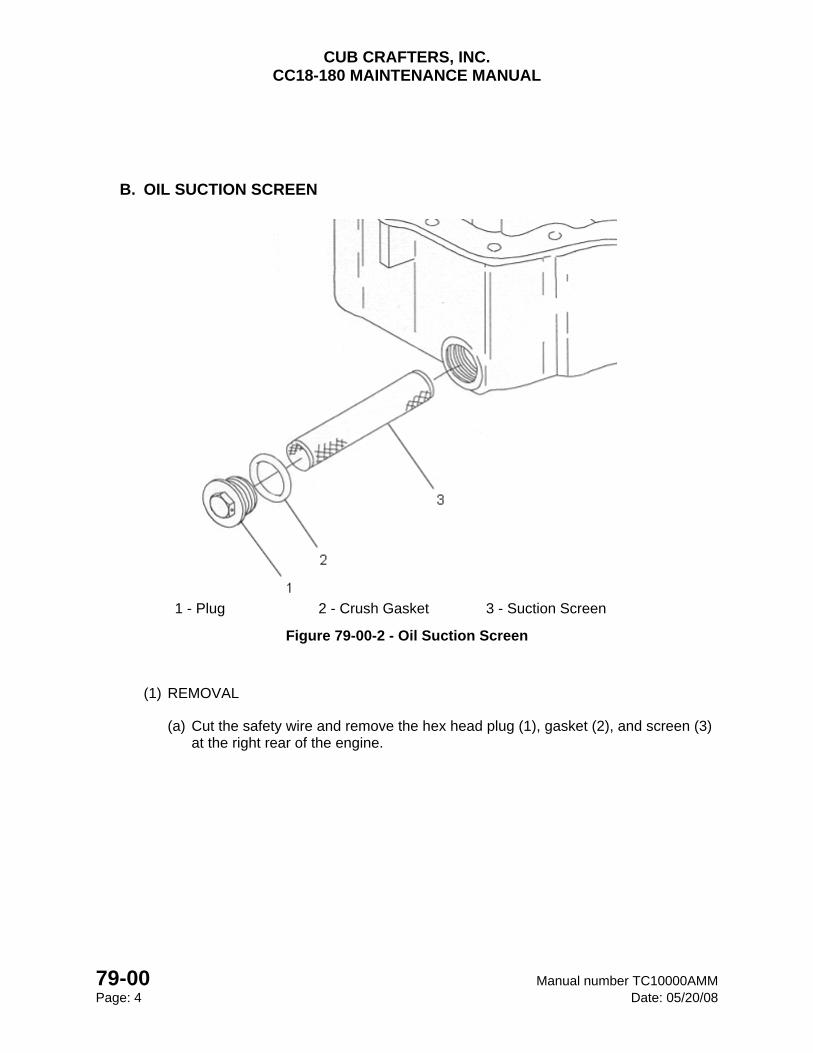
CUB CRAFTERS, INC. CC18-180 MAINTENANCE MANUAL
79-00 Manual number TC10000AMM Page: 4 Date: 05/20/08
B. OIL SUCTION SCREEN
1 - Plug 2 - Crush Gasket 3 - Suction Screen
Figure 79-00-2 - Oil Suction Screen
(1) REMOVAL
(a) Cut the safety wire and remove the hex head plug (1), gasket (2), and screen (3) at the right rear of the engine.
CUB CRAFTERS, INC. CC18-180 MAINTENANCE MANUAL
Manual number TC10000AMM 79-00 Date: 05/20/08 Page: 5
(2) INSPECTION
(a) Inspect the screen (2) for metal particles.
CAUTION
If examination of the suction screen indicates abnormal metal content, additional service may be required to determine the source and possible need for corrective
maintenance
(3) INSTALLATION
(a) Insert the screen (3) and plug (1) with a new copper crush gasket (2) with the unbroken surface against the plug.
(b) Turn the plug until the sealing surfaces are in contact and tighten 135º.
(c) Safety the plug with 0.032 safety wire.
(d) Service the engine with oil (Refer to 12-20).
(e) Run the engine and check for correct oil pressure and oil leaks. (Refer to 05-30).
(f) Check the oil level.
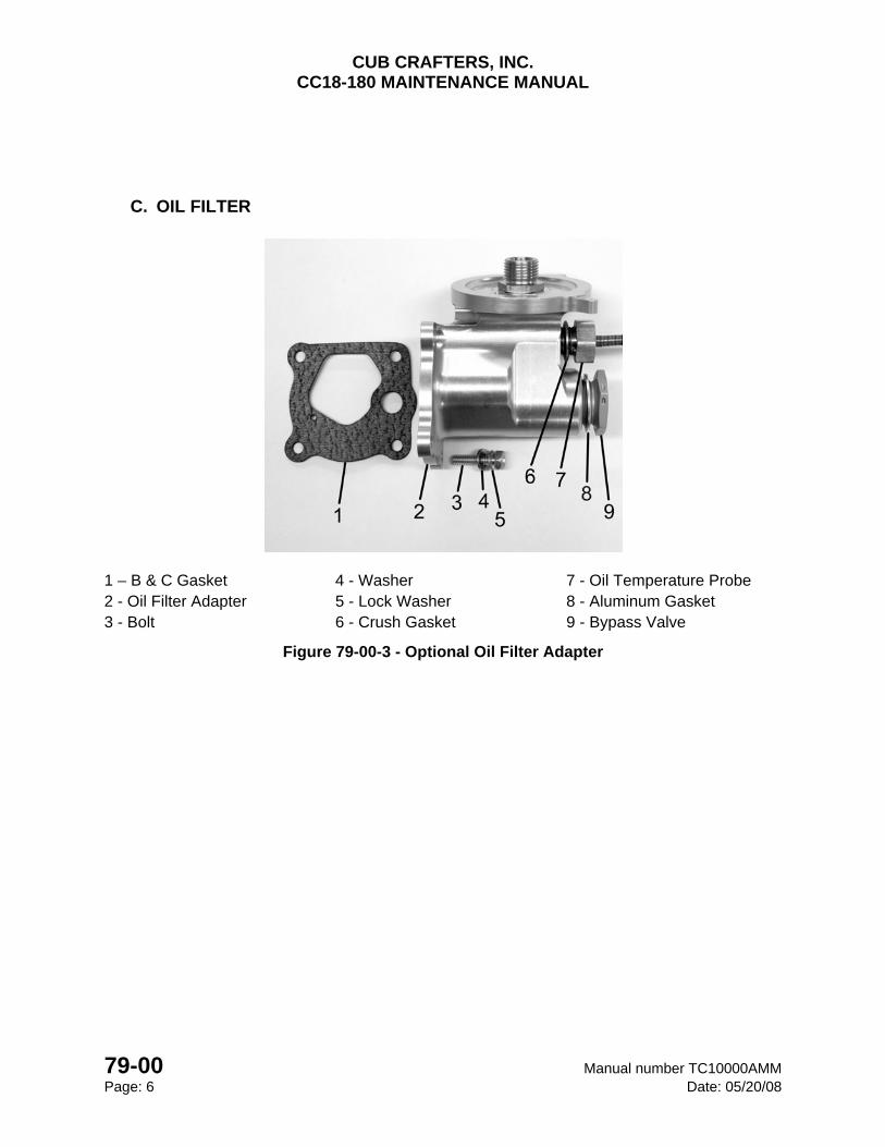
CUB CRAFTERS, INC. CC18-180 MAINTENANCE MANUAL
79-00 Manual number TC10000AMM Page: 6 Date: 05/20/08
C. OIL FILTER
1 – B & C Gasket 4 - Washer 7 - Oil Temperature Probe 2 - Oil Filter Adapter 5 - Lock Washer 8 - Aluminum Gasket 3 - Bolt 6 - Crush Gasket 9 - Bypass Valve
Figure 79-00-3 - Optional Oil Filter Adapter
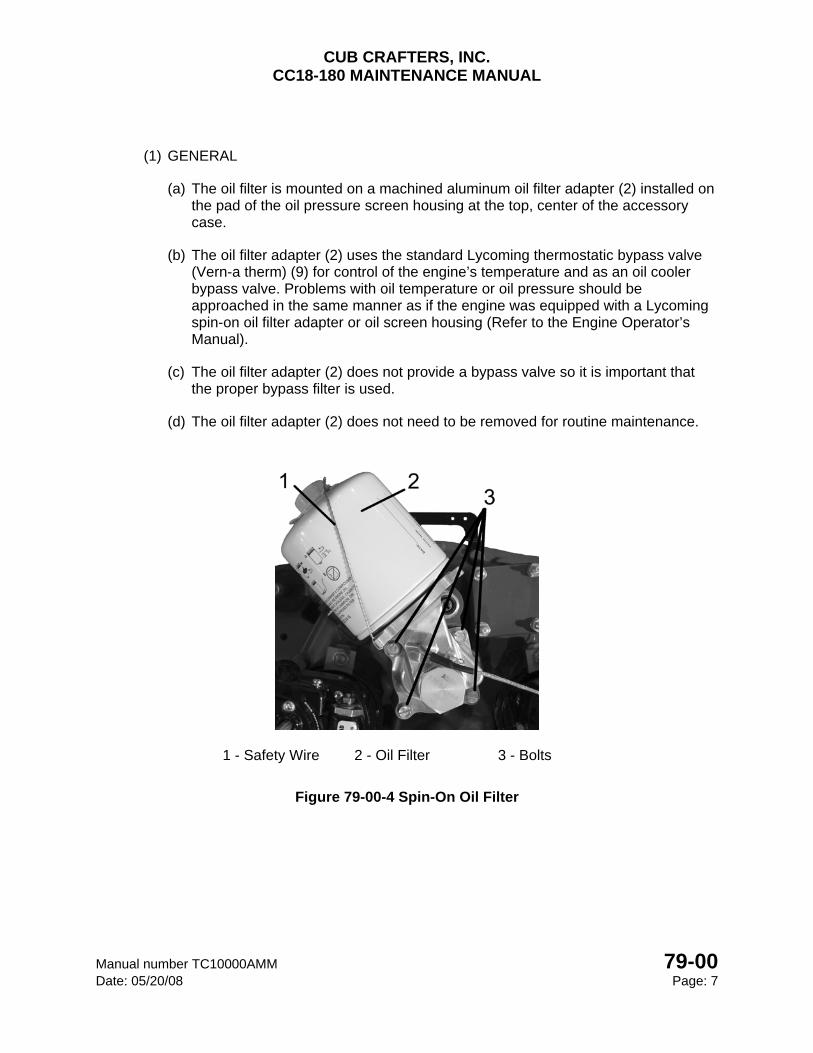
CUB CRAFTERS, INC. CC18-180 MAINTENANCE MANUAL
Manual number TC10000AMM 79-00 Date: 05/20/08 Page: 7
(1) GENERAL
(a) The oil filter is mounted on a machined aluminum oil filter adapter (2) installed on the pad of the oil pressure screen housing at the top, center of the accessory case.
(b) The oil filter adapter (2) uses the standard Lycoming thermostatic bypass valve (Vern-a therm) (9) for control of the engine’s temperature and as an oil cooler bypass valve. Problems with oil temperature or oil pressure should be approached in the same manner as if the engine was equipped with a Lycoming spin-on oil filter adapter or oil screen housing (Refer to the Engine Operator’s Manual).
(c) The oil filter adapter (2) does not provide a bypass valve so it is important that the proper bypass filter is used.
(d) The oil filter adapter (2) does not need to be removed for routine maintenance.
1 - Safety Wire 2 - Oil Filter 3 - Bolts
Figure 79-00-4 Spin-On Oil Filter
CUB CRAFTERS, INC. CC18-180 MAINTENANCE MANUAL
79-00 Manual number TC10000AMM Page: 8 Date: 05/20/08
(2) REMOVAL
(a) Poke a hole in the top of the oil filter (2) with an awl.
(b) Remove the safety wire (1) and the filter (2).
(c) Drain the oil (Refer to 12-20).
(d) After 45 minutes to 1 hour of draining, remove the filter (this will ensure minimal oil leakage). Use a plastic bag (2' X 2') that has a drawstring. Break the initial torque loose on the filter. Put the plastic bag over the filter and pull the drawstrings tight around the oil filter adapter flange and unscrew the filter inside the plastic bag. NO MESS!
(3) INSPECTION
(a) Open the filter and carefully unfold the paper element and examine the material trapped in the filter.
CAUTION
If examination of the filter paper element indicates abnormal metal content, additional service may be required to determine the source and possible need for corrective
maintenance
(4) INSTALLATION
(a) Lubricate the oil filter base gasket with D–C 4 (Refer to 12-20). If unavailable, use clean engine oil. Do not use dirty engine oil to lubricate the filter base gasket. Dirty engine oil will make the oil filter difficult to remove later on.
(b) Install the spin-on oil filter (2) and torque to 192-216 in/lbs.
(c) Safety (1) the filter in same sense as you would turn the filter to tighten it with 0.032 safety wire (Figure 79-00-4).
(d) Service the engine with oil (Refer to 12-20).
CAUTION Do not tighten the spin-on filter beyond the specified maximum torque. Over tightening
will make the filter extremely difficult to remove. Always use a 6 point, 1 inch socket when tightening a filter.
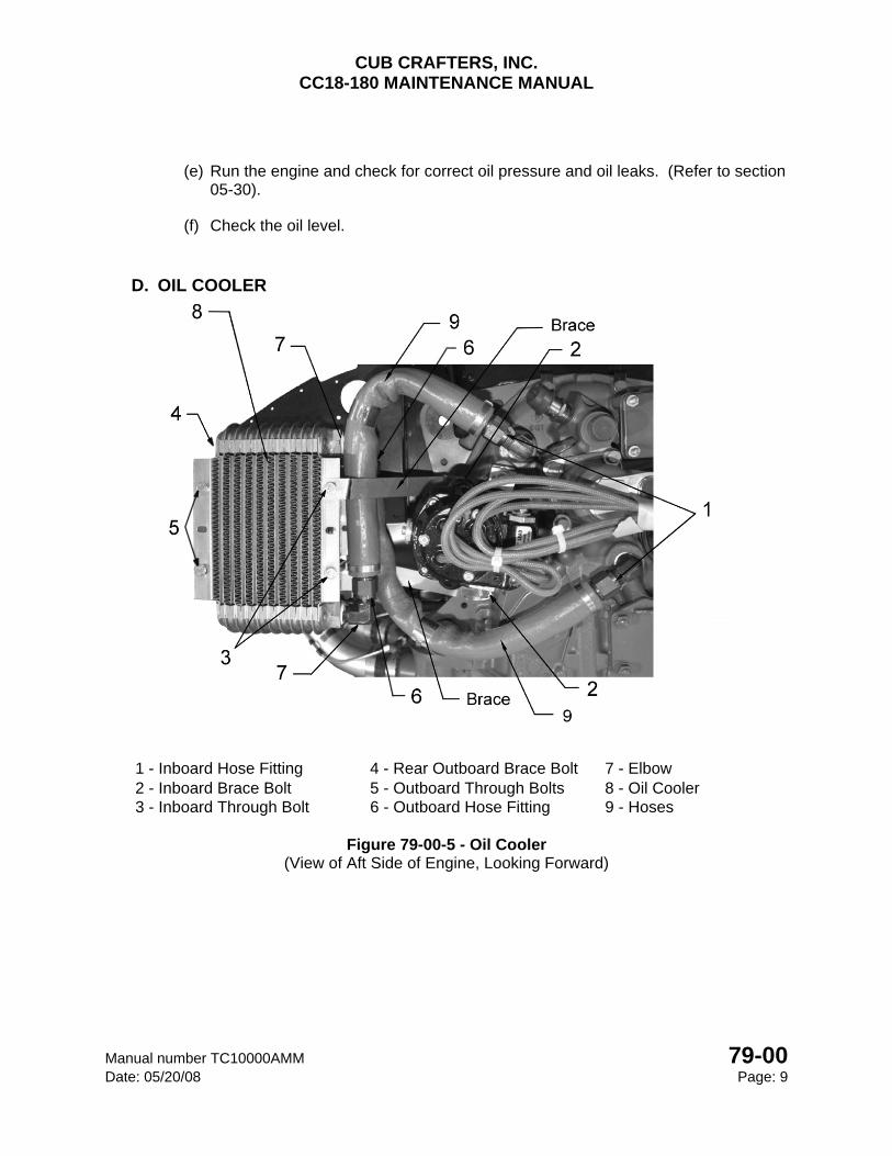
CUB CRAFTERS, INC. CC18-180 MAINTENANCE MANUAL
Manual number TC10000AMM 79-00 Date: 05/20/08 Page: 9
(e) Run the engine and check for correct oil pressure and oil leaks. (Refer to section 05-30).
(f) Check the oil level.
D. OIL COOLER
1 - Inboard Hose Fitting 4 - Rear Outboard Brace Bolt 7 - Elbow 2 - Inboard Brace Bolt 5 - Outboard Through Bolts 8 - Oil Cooler 3 - Inboard Through Bolt 6 - Outboard Hose Fitting 9 - Hoses
Figure 79-00-5 - Oil Cooler
(View of Aft Side of Engine, Looking Forward)
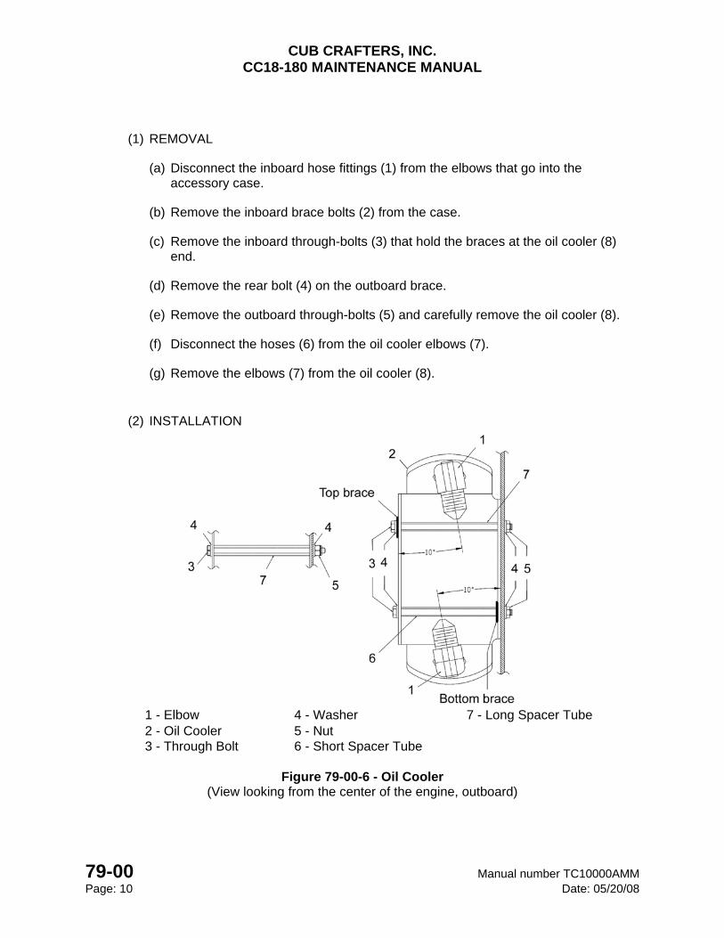
CUB CRAFTERS, INC. CC18-180 MAINTENANCE MANUAL
79-00 Manual number TC10000AMM Page: 10 Date: 05/20/08
(1) REMOVAL
(a) Disconnect the inboard hose fittings (1) from the elbows that go into the accessory case.
(b) Remove the inboard brace bolts (2) from the case.
(c) Remove the inboard through-bolts (3) that hold the braces at the oil cooler (8) end.
(d) Remove the rear bolt (4) on the outboard brace.
(e) Remove the outboard through-bolts (5) and carefully remove the oil cooler (8).
(f) Disconnect the hoses (6) from the oil cooler elbows (7).
(g) Remove the elbows (7) from the oil cooler (8).
(2) INSTALLATION
1 - Elbow 4 - Washer 7 - Long Spacer Tube 2 - Oil Cooler 5 - Nut 3 - Through Bolt 6 - Short Spacer Tube
Figure 79-00-6 - Oil Cooler
(View looking from the center of the engine, outboard)
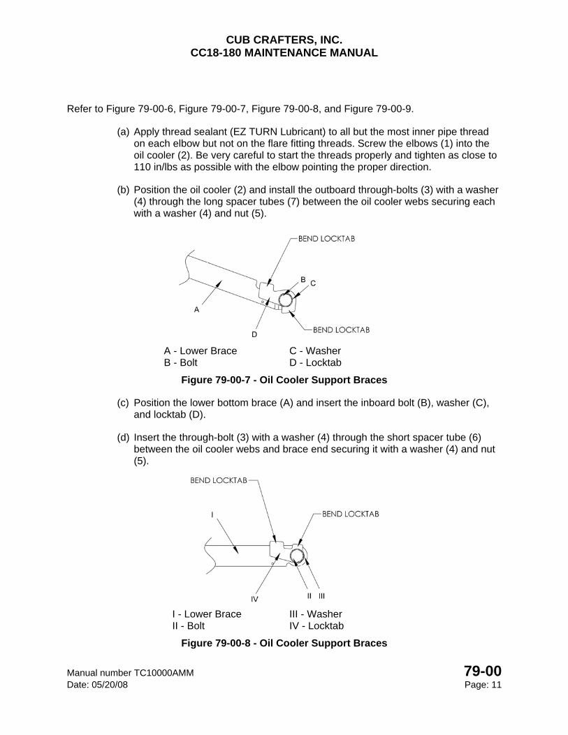
CUB CRAFTERS, INC. CC18-180 MAINTENANCE MANUAL
Manual number TC10000AMM 79-00 Date: 05/20/08 Page: 11
Refer to Figure 79-00-6, Figure 79-00-7, Figure 79-00-8, and Figure 79-00-9.
(a) Apply thread sealant (EZ TURN Lubricant) to all but the most inner pipe thread on each elbow but not on the flare fitting threads. Screw the elbows (1) into the oil cooler (2). Be very careful to start the threads properly and tighten as close to 110 in/lbs as possible with the elbow pointing the proper direction.
(b) Position the oil cooler (2) and install the outboard through-bolts (3) with a washer (4) through the long spacer tubes (7) between the oil cooler webs securing each with a washer (4) and nut (5).
A - Lower Brace C - Washer B - Bolt D - Locktab
Figure 79-00-7 - Oil Cooler Support Braces
(c) Position the lower bottom brace (A) and insert the inboard bolt (B), washer (C), and locktab (D).
(d) Insert the through-bolt (3) with a washer (4) through the short spacer tube (6) between the oil cooler webs and brace end securing it with a washer (4) and nut (5).
I - Lower Brace III - Washer II - Bolt IV - Locktab
Figure 79-00-8 - Oil Cooler Support Braces
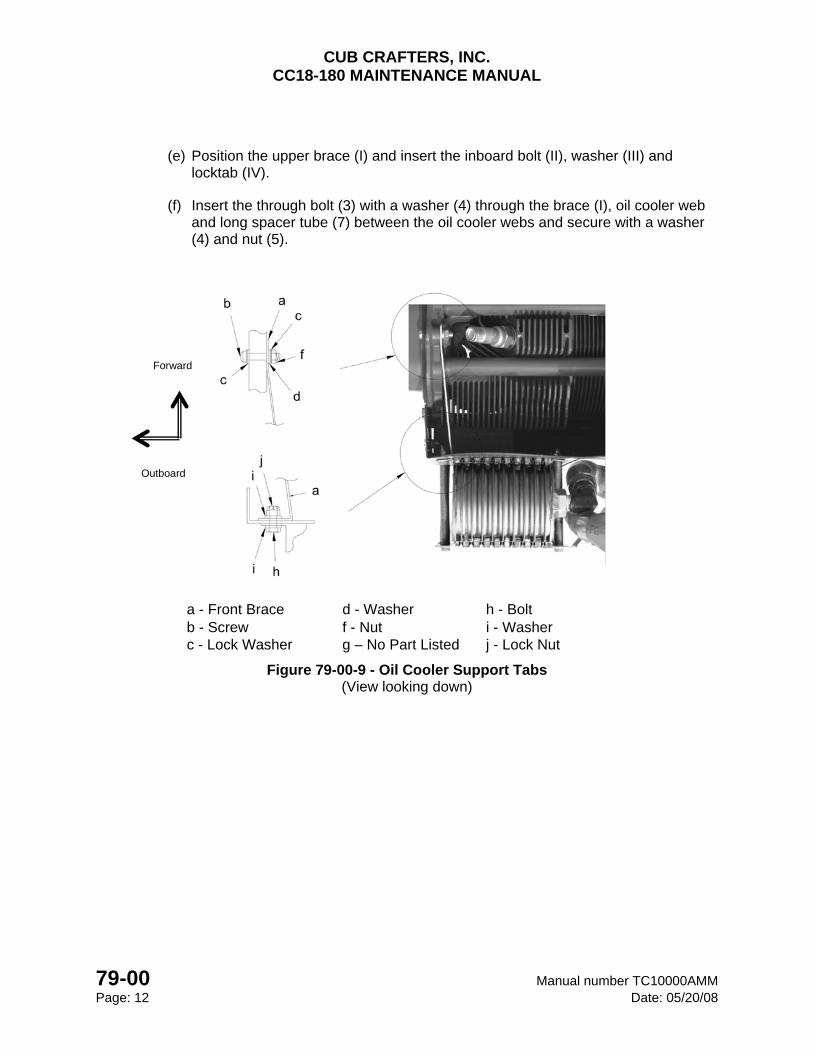
CUB CRAFTERS, INC. CC18-180 MAINTENANCE MANUAL
79-00 Manual number TC10000AMM Page: 12 Date: 05/20/08
(e) Position the upper brace (I) and insert the inboard bolt (II), washer (III) and locktab (IV).
(f) Insert the through bolt (3) with a washer (4) through the brace (I), oil cooler web and long spacer tube (7) between the oil cooler webs and secure with a washer (4) and nut (5).
a - Front Brace d - Washer h - Bolt b - Screw f - Nut i - Washer c - Lock Washer g – No Part Listed j - Lock Nut
Figure 79-00-9 - Oil Cooler Support Tabs (View looking down)
Outboard
Forward
CUB CRAFTERS, INC. CC18-180 MAINTENANCE MANUAL
Manual number TC10000AMM 79-00 Date: 05/20/08 Page: 13
(g) Attach the forward end of the front brace (a) to the end of the long rocker cover screw (b) of cylinder #4, securing it with a washer (d) lock washer (c) and nut (f) and torque to 50 in/lbs. maximum. Secure the rear end with a bolt (h), washers (i) and nut (j) and torque to 38-43 in/lbs.
(h) Torque the inboard brace bolts on the accessory case to 96 in/lbs maximum and bend lock-tabs to safety.
(i) Torque the four through-bolt nuts to 38-43 in/lbs.
(j) Attach the longer oil hose to the upper elbow (which points down) on the oil cooler and tighten the fitting to 55-65 in/lbs while holding the elbow with a wrench.
(k) Connect the inboard end of the hose to the lower elbow on the accessory case and tighten the fitting to 55-65 in/lbs while holding the elbow with a wrench.
(l) Attach the shorter oil hose to the elbow that is pointing up on the oil cooler and tighten the fitting to 55-65 in/lbs while holding the elbow with a wrench.
(m) Connect the inboard end of the hose to the upper elbow on the accessory case and tighten the fitting to 55-65 in/lbs while holding the elbow with a wrench.
CUB CRAFTERS, INC. CC18-180 MAINTENANCE MANUAL
79-00 Manual number TC10000AMM Page: 14 Date: 05/20/08
INTENTIONALLY LEFT BLANK
CHAPTER
80-00
STARTER


CUB CRAFTERS, INC. CC18-180 MAINTENANCE MANUAL
Manual number TC10000AMM 80-00 Date: 05/20/08 Page: 1
80-00 STARTER
TABLE OF CONTENTS 1. GENERAL .............................................................................................................................. 2
2. MAINTENANCE PRACTICES ............................................................................................... 2
(1) REMOVAL ..................................................................................................................... 3
(2) INSPECTION................................................................................................................. 3
(3) INSTALLATION ............................................................................................................. 3
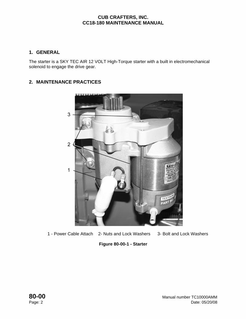
CUB CRAFTERS, INC. CC18-180 MAINTENANCE MANUAL
80-00 Manual number TC10000AMM Page: 2 Date: 05/20/08
1. GENERAL
The starter is a SKY TEC AIR 12 VOLT High-Torque starter with a built in electromechanical solenoid to engage the drive gear.
2. MAINTENANCE PRACTICES
1 - Power Cable Attach 2- Nuts and Lock Washers 3- Bolt and Lock Washers
Figure 80-00-1 - Starter
CUB CRAFTERS, INC. CC18-180 MAINTENANCE MANUAL
Manual number TC10000AMM 80-00 Date: 05/20/08 Page: 3
(1) REMOVAL
(a) Disconnect the power cable (1).
(b) Unbolt the starter attachment bolt (3) and nut (2).
(2) INSPECTION
(a) Visually inspect the teeth of the starter gear and starter’s housing for damage.
(3) INSTALLATION
(a) Secure the starter using new lock washers (2, 3).
(b) Torque the bolts (3) and nuts (2) to 95-105 in/lbs.
(c) Attach the power cable using the metric nut and new lock washer (1). Torque the nut to 50-60 in/lbs.
CAUTION
Do not over torque the nut on the copper stud.

CUB CRAFTERS, INC. CC18-180 MAINTENANCE MANUAL
80-00 Manual number TC10000AMM Page: 4 Date: 05/20/08
INTENTIONALLY LEFT BLANK
CHAPTER
95-00
SPECIAL PURPOSE
EQUIPMENT

CUB CRAFTERS, INC. CC18-180 MAINTENANCE MANUAL
Manual number TC10000 95-00 Date: 05/20/08 Page: 1
95-00 SPECIAL PURPOSE EQUIPMENT
Table of Contents 1. GENERAL ......................................................................................................................... 2
2. TOOLING .......................................................................................................................... 2
A. TL4000-001 FLOAT AXLE EXTENSION ...................................................................... 2
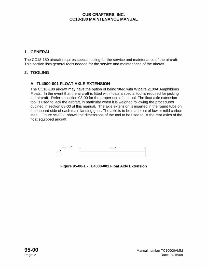
CUB CRAFTERS, INC. CC18-180 MAINTENANCE MANUAL
95-00 Manual number TC10000AMM Page: 2 Date: 04/16/08
" "
1. GENERAL
The CC18-180 aircraft requires special tooling for the service and maintenance of the aircraft. This section lists general tools needed for the service and maintenance of the aircraft.
2. TOOLING
A. TL4000-001 FLOAT AXLE EXTENSION The CC18-180 aircraft may have the option of being fitted with Wipaire 2100A Amphibious Floats. In the event that the aircraft is fitted with floats a special tool is required for jacking the aircraft. Refer to section 08-00 for the proper use of the tool. The float axle extension tool is used to jack the aircraft, in particular when it is weighed following the procedures outlined in section 08-00 of this manual. The axle extension is inserted in the round tube on the inboard side of each main landing gear. The axle is to be made out of low or mild carbon steel. Figure 95-00-1 shows the dimensions of the tool to be used to lift the rear axles of the float equipped aircraft.
Figure 95-00-1 - TL4000-001 Float Axle Extension

APPENDIX A
CONVERSIONS

CUB CRAFTERS, INC. CC18-180 MAINTENANCE MANUAL
Manual number TC10000 APPENDIX A Date: 05/20/08 Page: 1
APPENDIX A CONVERSIONS
Table of Contents
I. CONVERSIONS .................................................................................................................... 2
A. WEIGHT - POUNDS INTO KILOGRAMS .................................................................... 2
B. LENGTH - FEET INTO METERS ................................................................................ 2
C. LENGTH - INCHES INTO CENTIMETERS .................................................................. 3
D. VOLUME - GALLONS INTO LITERS .......................................................................... 3
E. TEMPERATURE - FAHRENHEIT INTO CELSIUS...................................................... 4
F. TORQUE - INCH POUNDS, FOOT POUNDS INTO NEWTON METERS ................... 4
G. SPEED - MILES PER HOUR INTO KNOTS ................................................................. 5
H. DISTANCE - STATUTE MILES, NAUTICAL MILES, AND KILOMETERS ................... 5
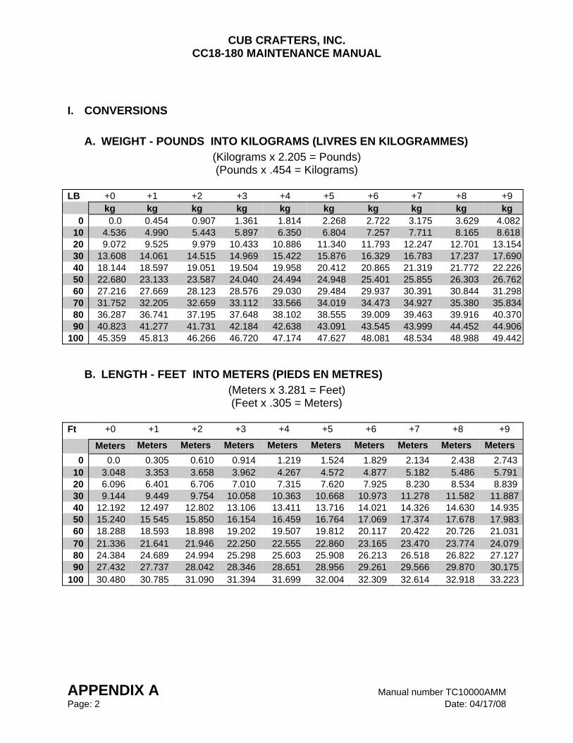
CUB CRAFTERS, INC. CC18-180 MAINTENANCE MANUAL
APPENDIX A Manual number TC10000AMM Page: 2 Date: 04/17/08
I. CONVERSIONS
A. WEIGHT - POUNDS INTO KILOGRAMS (LIVRES EN KILOGRAMMES) (Kilograms x 2.205 = Pounds) (Pounds x .454 = Kilograms)
LB +0 +1 +2 +3 +4 +5 +6 +7 +8 +9 kg kg kg kg kg kg kg kg kg kg
0 0.0 0.454 0.907 1.361 1.814 2.268 2.722 3.175 3.629 4.08210 4.536 4.990 5.443 5.897 6.350 6.804 7.257 7.711 8.165 8.61820 9.072 9.525 9.979 10.433 10.886 11.340 11.793 12.247 12.701 13.15430 13.608 14.061 14.515 14.969 15.422 15.876 16.329 16.783 17.237 17.69040 18.144 18.597 19.051 19.504 19.958 20.412 20.865 21.319 21.772 22.22650 22.680 23.133 23.587 24.040 24.494 24.948 25.401 25.855 26.303 26.76260 27.216 27.669 28.123 28.576 29.030 29.484 29.937 30.391 30.844 31.29870 31.752 32.205 32.659 33.112 33.566 34.019 34.473 34.927 35.380 35.83480 36.287 36.741 37.195 37.648 38.102 38.555 39.009 39.463 39.916 40.37090 40.823 41.277 41.731 42.184 42.638 43.091 43.545 43.999 44.452 44.906
100 45.359 45.813 46.266 46.720 47.174 47.627 48.081 48.534 48.988 49.442
B. LENGTH - FEET INTO METERS (PIEDS EN METRES) (Meters x 3.281 = Feet) (Feet x .305 = Meters)
Ft +0 +1 +2 +3 +4 +5 +6 +7 +8 +9
Meters Meters Meters Meters Meters Meters Meters Meters Meters Meters 0 0.0 0.305 0.610 0.914 1.219 1.524 1.829 2.134 2.438 2.743
10 3.048 3.353 3.658 3.962 4.267 4.572 4.877 5.182 5.486 5.791 20 6.096 6.401 6.706 7.010 7.315 7.620 7.925 8.230 8.534 8.839 30 9.144 9.449 9.754 10.058 10.363 10.668 10.973 11.278 11.582 11.88740 12.192 12.497 12.802 13.106 13.411 13.716 14.021 14.326 14.630 14.93550 15.240 15 545 15.850 16.154 16.459 16.764 17.069 17.374 17.678 17.98360 18.288 18.593 18.898 19.202 19.507 19.812 20.117 20.422 20.726 21.03170 21.336 21.641 21.946 22.250 22.555 22.860 23.165 23.470 23.774 24.07980 24.384 24.689 24.994 25.298 25.603 25.908 26.213 26.518 26.822 27.12790 27.432 27.737 28.042 28.346 28.651 28.956 29.261 29.566 29.870 30.175
100 30.480 30.785 31.090 31.394 31.699 32.004 32.309 32.614 32.918 33.223
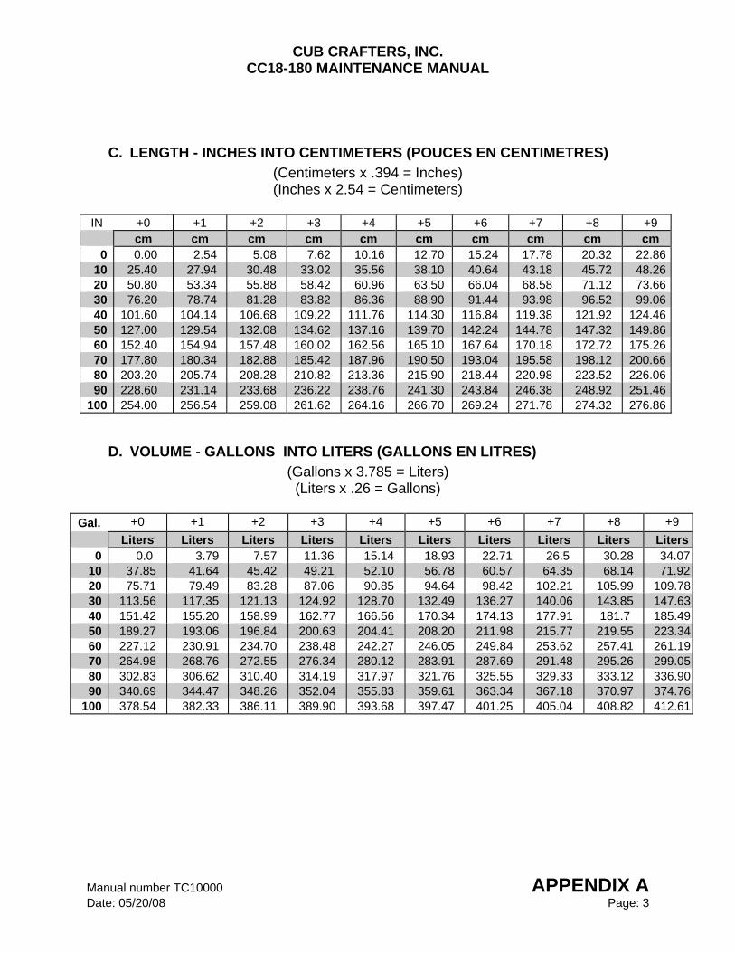
CUB CRAFTERS, INC. CC18-180 MAINTENANCE MANUAL
Manual number TC10000 APPENDIX A Date: 05/20/08 Page: 3
C. LENGTH - INCHES INTO CENTIMETERS (POUCES EN CENTIMETRES) (Centimeters x .394 = Inches) (Inches x 2.54 = Centimeters)
IN +0 +1 +2 +3 +4 +5 +6 +7 +8 +9 cm cm cm cm cm cm cm cm cm cm 0 0.00 2.54 5.08 7.62 10.16 12.70 15.24 17.78 20.32 22.86
10 25.40 27.94 30.48 33.02 35.56 38.10 40.64 43.18 45.72 48.2620 50.80 53.34 55.88 58.42 60.96 63.50 66.04 68.58 71.12 73.6630 76.20 78.74 81.28 83.82 86.36 88.90 91.44 93.98 96.52 99.0640 101.60 104.14 106.68 109.22 111.76 114.30 116.84 119.38 121.92 124.4650 127.00 129.54 132.08 134.62 137.16 139.70 142.24 144.78 147.32 149.8660 152.40 154.94 157.48 160.02 162.56 165.10 167.64 170.18 172.72 175.2670 177.80 180.34 182.88 185.42 187.96 190.50 193.04 195.58 198.12 200.6680 203.20 205.74 208.28 210.82 213.36 215.90 218.44 220.98 223.52 226.0690 228.60 231.14 233.68 236.22 238.76 241.30 243.84 246.38 248.92 251.46
100 254.00 256.54 259.08 261.62 264.16 266.70 269.24 271.78 274.32 276.86
D. VOLUME - GALLONS INTO LITERS (GALLONS EN LITRES) (Gallons x 3.785 = Liters) (Liters x .26 = Gallons)
Gal. +0 +1 +2 +3 +4 +5 +6 +7 +8 +9
Liters Liters Liters Liters Liters Liters Liters Liters Liters Liters0 0.0 3.79 7.57 11.36 15.14 18.93 22.71 26.5 30.28 34.07
10 37.85 41.64 45.42 49.21 52.10 56.78 60.57 64.35 68.14 71.9220 75.71 79.49 83.28 87.06 90.85 94.64 98.42 102.21 105.99 109.7830 113.56 117.35 121.13 124.92 128.70 132.49 136.27 140.06 143.85 147.6340 151.42 155.20 158.99 162.77 166.56 170.34 174.13 177.91 181.7 185.4950 189.27 193.06 196.84 200.63 204.41 208.20 211.98 215.77 219.55 223.3460 227.12 230.91 234.70 238.48 242.27 246.05 249.84 253.62 257.41 261.1970 264.98 268.76 272.55 276.34 280.12 283.91 287.69 291.48 295.26 299.0580 302.83 306.62 310.40 314.19 317.97 321.76 325.55 329.33 333.12 336.9090 340.69 344.47 348.26 352.04 355.83 359.61 363.34 367.18 370.97 374.76
100 378.54 382.33 386.11 389.90 393.68 397.47 401.25 405.04 408.82 412.61
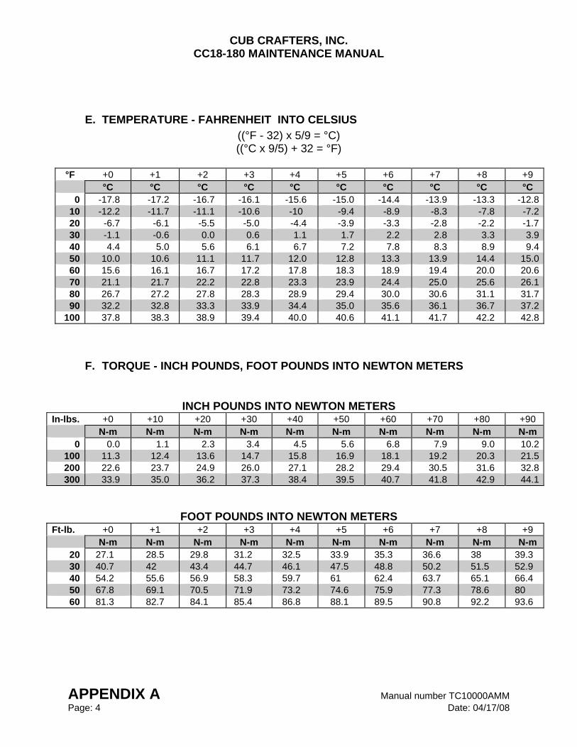
CUB CRAFTERS, INC. CC18-180 MAINTENANCE MANUAL
APPENDIX A Manual number TC10000AMM Page: 4 Date: 04/17/08
E. TEMPERATURE - FAHRENHEIT INTO CELSIUS ((°F - 32) x 5/9 = °C) ((°C x 9/5) + 32 = °F)
°F +0 +1 +2 +3 +4 +5 +6 +7 +8 +9
°C °C °C °C °C °C °C °C °C °C 0 -17.8 -17.2 -16.7 -16.1 -15.6 -15.0 -14.4 -13.9 -13.3 -12.8
10 -12.2 -11.7 -11.1 -10.6 -10 -9.4 -8.9 -8.3 -7.8 -7.220 -6.7 -6.1 -5.5 -5.0 -4.4 -3.9 -3.3 -2.8 -2.2 -1.730 -1.1 -0.6 0.0 0.6 1.1 1.7 2.2 2.8 3.3 3.940 4.4 5.0 5.6 6.1 6.7 7.2 7.8 8.3 8.9 9.450 10.0 10.6 11.1 11.7 12.0 12.8 13.3 13.9 14.4 15.060 15.6 16.1 16.7 17.2 17.8 18.3 18.9 19.4 20.0 20.670 21.1 21.7 22.2 22.8 23.3 23.9 24.4 25.0 25.6 26.180 26.7 27.2 27.8 28.3 28.9 29.4 30.0 30.6 31.1 31.790 32.2 32.8 33.3 33.9 34.4 35.0 35.6 36.1 36.7 37.2
100 37.8 38.3 38.9 39.4 40.0 40.6 41.1 41.7 42.2 42.8
F. TORQUE - INCH POUNDS, FOOT POUNDS INTO NEWTON METERS
INCH POUNDS INTO NEWTON METERS In-lbs. +0 +10 +20 +30 +40 +50 +60 +70 +80 +90 N-m N-m N-m N-m N-m N-m N-m N-m N-m N-m
0 0.0 1.1 2.3 3.4 4.5 5.6 6.8 7.9 9.0 10.2100 11.3 12.4 13.6 14.7 15.8 16.9 18.1 19.2 20.3 21.5200 22.6 23.7 24.9 26.0 27.1 28.2 29.4 30.5 31.6 32.8300 33.9 35.0 36.2 37.3 38.4 39.5 40.7 41.8 42.9 44.1
FOOT POUNDS INTO NEWTON METERS Ft-lb. +0 +1 +2 +3 +4 +5 +6 +7 +8 +9 N-m N-m N-m N-m N-m N-m N-m N-m N-m N-m
20 27.1 28.5 29.8 31.2 32.5 33.9 35.3 36.6 38 39.3 30 40.7 42 43.4 44.7 46.1 47.5 48.8 50.2 51.5 52.9 40 54.2 55.6 56.9 58.3 59.7 61 62.4 63.7 65.1 66.4 50 67.8 69.1 70.5 71.9 73.2 74.6 75.9 77.3 78.6 80 60 81.3 82.7 84.1 85.4 86.8 88.1 89.5 90.8 92.2 93.6
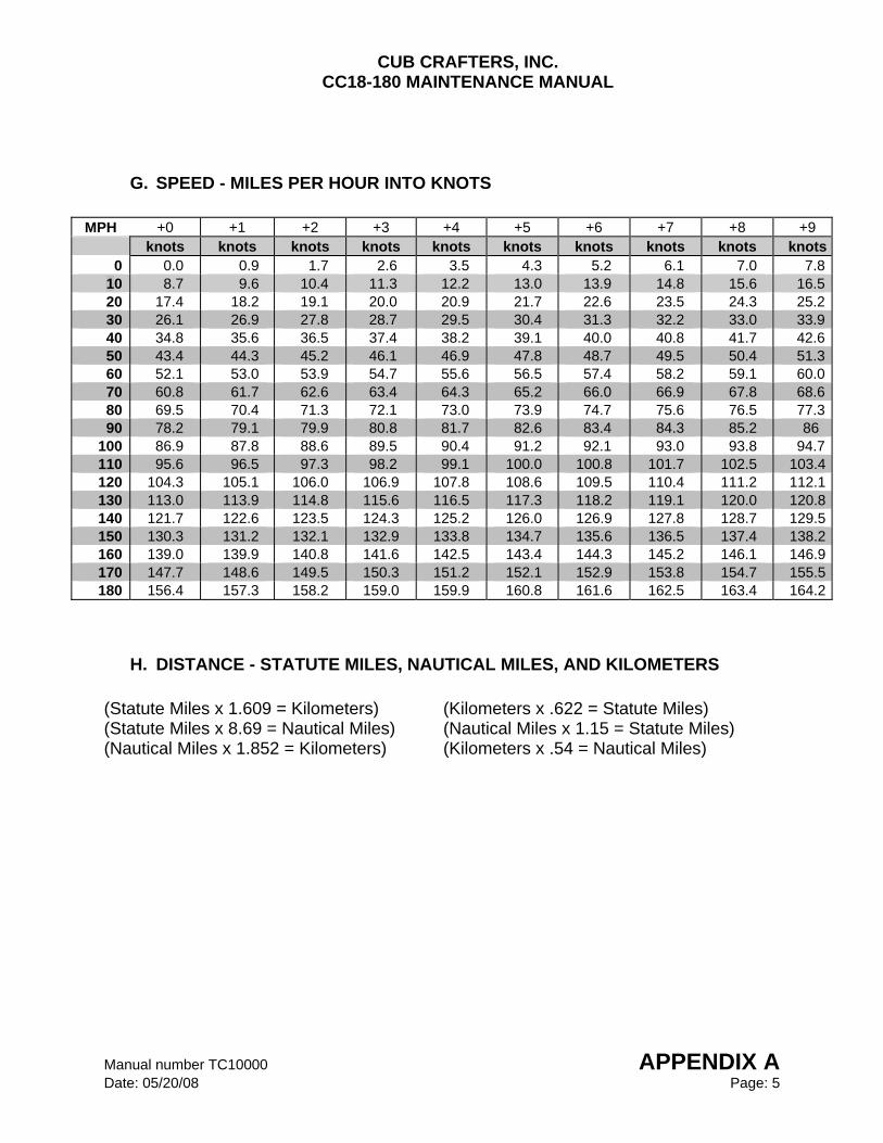
CUB CRAFTERS, INC. CC18-180 MAINTENANCE MANUAL
Manual number TC10000 APPENDIX A Date: 05/20/08 Page: 5
G. SPEED - MILES PER HOUR INTO KNOTS
MPH +0 +1 +2 +3 +4 +5 +6 +7 +8 +9
knots knots knots knots knots knots knots knots knots knots0 0.0 0.9 1.7 2.6 3.5 4.3 5.2 6.1 7.0 7.8
10 8.7 9.6 10.4 11.3 12.2 13.0 13.9 14.8 15.6 16.520 17.4 18.2 19.1 20.0 20.9 21.7 22.6 23.5 24.3 25.230 26.1 26.9 27.8 28.7 29.5 30.4 31.3 32.2 33.0 33.940 34.8 35.6 36.5 37.4 38.2 39.1 40.0 40.8 41.7 42.650 43.4 44.3 45.2 46.1 46.9 47.8 48.7 49.5 50.4 51.360 52.1 53.0 53.9 54.7 55.6 56.5 57.4 58.2 59.1 60.070 60.8 61.7 62.6 63.4 64.3 65.2 66.0 66.9 67.8 68.680 69.5 70.4 71.3 72.1 73.0 73.9 74.7 75.6 76.5 77.390 78.2 79.1 79.9 80.8 81.7 82.6 83.4 84.3 85.2 86
100 86.9 87.8 88.6 89.5 90.4 91.2 92.1 93.0 93.8 94.7110 95.6 96.5 97.3 98.2 99.1 100.0 100.8 101.7 102.5 103.4120 104.3 105.1 106.0 106.9 107.8 108.6 109.5 110.4 111.2 112.1130 113.0 113.9 114.8 115.6 116.5 117.3 118.2 119.1 120.0 120.8140 121.7 122.6 123.5 124.3 125.2 126.0 126.9 127.8 128.7 129.5150 130.3 131.2 132.1 132.9 133.8 134.7 135.6 136.5 137.4 138.2160 139.0 139.9 140.8 141.6 142.5 143.4 144.3 145.2 146.1 146.9170 147.7 148.6 149.5 150.3 151.2 152.1 152.9 153.8 154.7 155.5180 156.4 157.3 158.2 159.0 159.9 160.8 161.6 162.5 163.4 164.2
H. DISTANCE - STATUTE MILES, NAUTICAL MILES, AND KILOMETERS (Statute Miles x 1.609 = Kilometers) (Kilometers x .622 = Statute Miles) (Statute Miles x 8.69 = Nautical Miles) (Nautical Miles x 1.15 = Statute Miles) (Nautical Miles x 1.852 = Kilometers) (Kilometers x .54 = Nautical Miles)
CUB CRAFTERS, INC. CC18-180 MAINTENANCE MANUAL
APPENDIX A Manual number TC10000AMM Page: 6 Date: 04/17/08
INTENTIONALLY LEFT BLANK