
CC121 Operation Manual - Steinbergdownload.steinberg.net/.../CC121_OperationManual_en.pdf · plied...
28
EN
Transcript of CC121 Operation Manual - Steinbergdownload.steinberg.net/.../CC121_OperationManual_en.pdf · plied...

EN
SPECIAL MESSAGE SECTION
This product utilizes batteries or an external power sup-ply (adapter). DO NOT connect this product to any power supply or adapter other than one described in the manual, on the name plate, or specifically recom-mended by Steinberg/Yamaha.WARNING: Do not place this product in a position where anyone could walk on, trip over, or roll anything over power or connecting cords of any kind. The use of an extension cord is not recommended! If you must use an extension cord, the minimum wire size for a 25’ cord (or less) is 18 AWG. NOTE: The smaller the AWG num-ber, the larger the current handling capacity. For longer extension cords, consult a local electrician.
This product should be used only with the components supplied or; a cart, rack, or stand that is recommended by Steinberg/Yamaha. If a cart, etc., is used, please observe all safety markings and instructions that accompany the accessory product.
SPECIFICATIONS SUBJECT TO CHANGE: The information contained in this manual is believed to be correct at the time of printing. However, Steinberg/Yamaha reserves the right to change or modify any of the specifications without notice or obligation to update existing units.
This product, either alone or in combination with an amplifier and headphones or speaker/s, may be capable of producing sound levels that could cause permanent hearing loss. DO NOT operate for long periods of time at a high volume level or at a level that is uncomfortable. If you experience any hearing loss or ringing in the ears, you should consult an audiologist. IMPORTANT: The louder the sound, the shorter the time period before damage occurs.
Some Steinberg/Yamaha products may have benchesand / or accessory mounting fixtures that are either sup-plied with the product or as optional accessories. Some of these items are designed to be dealer assembled or installed. Please make sure that benches are stable and any optional fixtures (where applicable) are well secured BEFORE using.Benches supplied by Steinberg/Yamaha are designed for seating only. No other uses are recommended.
NOTICE: Service charges incurred due to a lack of knowledge relating to how a function or effect works (when the unit is operating as designed) are not covered by the manu-facturer’s warranty, and are therefore the owners responsibility. Please study this manual carefully and consult your dealer before requesting service.
ENVIRONMENTAL ISSUES: Steinberg/Yamaha strives to produce products that are both user safe and environmentally friendly. We sin-cerely believe that our products and the production methods used to produce them, meet these goals. In keeping with both the letter and the spirit of the law, we want you to be aware of the following:
Battery Notice: This product MAY contain a small non-rechargeable battery which (if applicable) is soldered in place. The average life span of this type of battery is approximately five years. When replacement becomes necessary, con-tact a qualified service representative to perform the replacement.
This product may also use “household” type batteries. Some of these may be rechargeable. Make sure that the battery being charged is a rechargeable type and that the charger is intended for the battery being charged.
When installing batteries, do not mix batteries with new, or with batteries of a different type. Batteries MUST be installed correctly. Mismatches or incorrect installation may result in overheating and battery case rupture.
Warning: Do not attempt to disassemble, or incinerate any bat-tery. Keep all batteries away from children. Dispose of used batteries promptly and as regulated by the laws in your area. Note: Check with any retailer of household type batteries in your area for battery disposal informa-tion.
Disposal Notice: Should this product become damaged beyond repair, or for some reason its useful life is considered to be at an end, please observe all local, state, and federal regula-tions that relate to the disposal of products that contain lead, batteries, plastics, etc. If your dealer is unable to assist you, please contact Steinberg/Yamaha directly.
NAME PLATE LOCATION: The name plate is located on the bottom of the product. The model number, serial number, power requirements, etc., are located on this plate. You should record the model number, serial number, and the date of purchase in the spaces provided below and retain this manual as a permanent record of your purchase.
Model
Serial No.
Purchase Date
PLEASE KEEP THIS MANUAL92-BP (bottom)

1. IMPORTANT NOTICE: DO NOT MODIFY does not guarantee that interference will not occur
FCC INFORMATION (U.S.A.)
THIS UNIT!This product, when installed as indicated in the instructions contained in this manual, meets FCC requirements. Modifications not expressly approved by Yamaha may void your authority, granted by the FCC, to use the product.
2. IMPORTANT: When connecting this product to accessories and/or another product use only high quality shielded cables. Cable/s supplied with this product MUST be used. Follow all installation instructions. Failure to follow instructions could void your FCC authorization to use this product in the USA.
3. NOTE: This product has been tested and found to comply with the requirements listed in FCC Regula-tions, Part 15 for Class “B” digital devices. Compli-ance with these requirements provides a reasonable level of assurance that your use of this product in a residential environment will not result in harmful interference with other electronic devices. This equipment generates/uses radio frequencies and, if not installed and used according to the instructions found in the users manual, may cause interference harmful to the operation of other elec-tronic devices. Compliance with FCC regulations
in all installations. If this product is found to be the source of interference, which can be determined by turning the unit “OFF” and “ON”, please try to elimi-nate the problem by using one of the following mea-sures:Relocate either this product or the device that is being affected by the interference. Utilize power outlets that are on different branch (circuit breaker or fuse) circuits or install AC line fil-ter/s.In the case of radio or TV interference, relocate/reorient the antenna. If the antenna lead-in is 300 ohm ribbon lead, change the lead-in to co-axial type cable.If these corrective measures do not produce satis-factory results, please contact the local retailer authorized to distribute this type of product. If you can not locate the appropriate retailer, please con-tact Yamaha Corporation of America, Electronic Service Division, 6600 Orangethorpe Ave, Buena Park, CA90620The above statements apply ONLY to those prod-ucts distributed by Yamaha Corporation of America or its subsidiaries.
* This applies only to products distributed by YAMAHA CORPORATION OF AMERICA. (class B)
This applies only to products distributed by
COMPLIANCE INFORMATION STATEMENT(DECLARATION OF CONFORMITY PROCEDURE)
Responsible Party : Yamaha Corporation of AmericaAddress : 6600 Orangethorpe Ave., Buena Park, Calif. 90620
Telephone : 714-522-9011Type of Equipment : ADVANCED INTEGRATION CONTROLLER
Model Name : CC121
This device complies with Part 15 of the FCC Rules.Operation is subject to the following two conditions:1) this device may not cause harmful interference, and2) this device must accept any interference received including interference
that may cause undesired operation.See user manual instructions if interference to radio reception is sus-pected.
(FCC DoC)
*YAMAHA CORPORATION OF AMERICA.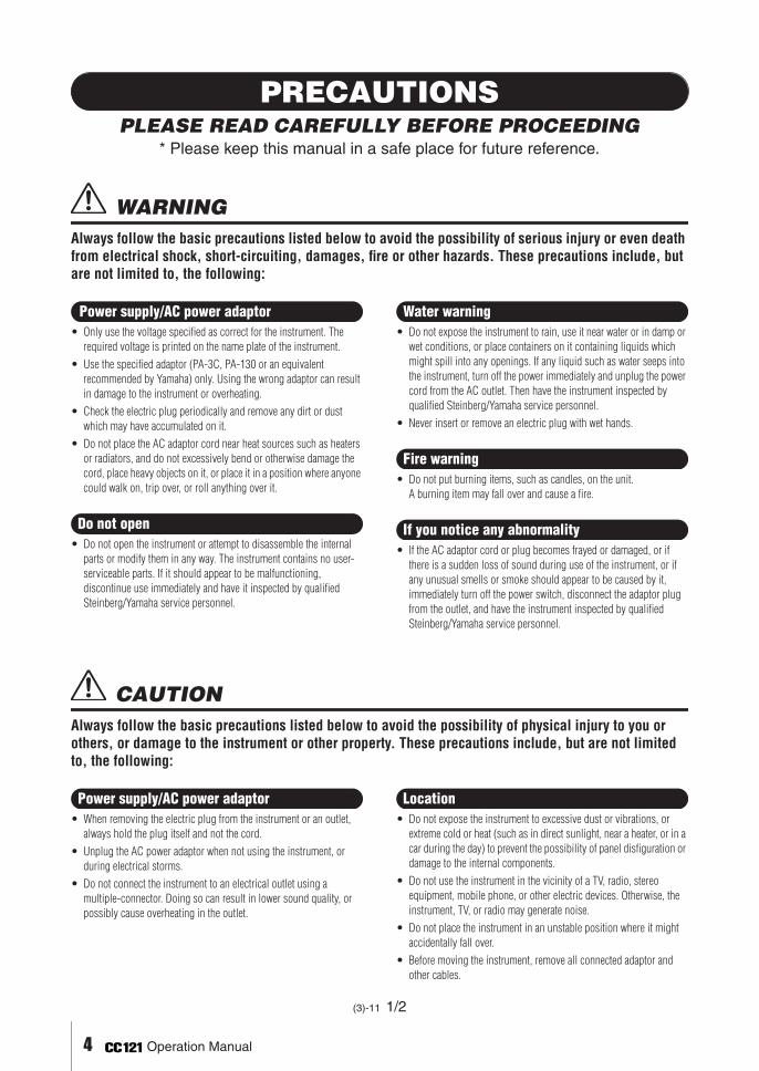
PRECAUTIONSPLEASE READ CAREFULLY BEFORE PROCEEDING
* Please keep this manual in a safe place for future reference.
WARNINGAlways follow the basic precautions listed below to avoid the possibility of serious injury or even death from electrical shock, short-circuiting, damages, fire or other hazards. These precautions include, but are not limited to, the following:
• Only use the voltage specified as correct for the instrument. The required voltage is printed on the name plate of the instrument.
• Use the specified adaptor (PA-3C, PA-130 or an equivalent recommended by Yamaha) only. Using the wrong adaptor can result in damage to the instrument or overheating.
• Check the electric plug periodically and remove any dirt or dust which may have accumulated on it.
• Do not place the AC adaptor cord near heat sources such as heaters or radiators, and do not excessively bend or otherwise damage the cord, place heavy objects on it, or place it in a position where anyone could walk on, trip over, or roll anything over it.
• Do not open the instrument or attempt to disassemble the internal parts or modify them in any way. The instrument contains no user-serviceable parts. If it should appear to be malfunctioning, discontinue use immediately and have it inspected by qualified Steinberg/Yamaha service personnel.
• Do not expose the instrument to rain, use it near water or in damp or wet conditions, or place containers on it containing liquids which might spill into any openings. If any liquid such as water seeps into the instrument, turn off the power immediately and unplug the power cord from the AC outlet. Then have the instrument inspected by qualified Steinberg/Yamaha service personnel.
• Never insert or remove an electric plug with wet hands.
• Do not put burning items, such as candles, on the unit. A burning item may fall over and cause a fire.
• If the AC adaptor cord or plug becomes frayed or damaged, or if there is a sudden loss of sound during use of the instrument, or if any unusual smells or smoke should appear to be caused by it,immediately turn off the power switch, disconnect the adaptor plug from the outlet, and have the instrument inspected by qualified Steinberg/Yamaha service personnel.
CAUTIONAlways follow the basic precautions listed below to avoid the possibility of physical injury to you or others, or damage to the instrument or other property. These precautions include, but are not limited to, the following:
• When removing the electric plug from the instrument or an outlet, always hold the plug itself and not the cord.
• Unplug the AC power adaptor when not using the instrument, or during electrical storms.
• Do not connect the instrument to an electrical outlet using a multiple-connector. Doing so can result in lower sound quality, or possibly cause overheating in the outlet.
• Do not expose the instrument to excessive dust or vibrations, or extreme cold or heat (such as in direct sunlight, near a heater, or in a car during the day) to prevent the possibility of panel disfiguration or damage to the internal components.
• Do not use the instrument in the vicinity of a TV, radio, stereo equipment, mobile phone, or other electric devices. Otherwise, the instrument, TV, or radio may generate noise.
• Do not place the instrument in an unstable position where it might accidentally fall over.
• Before moving the instrument, remove all connected adaptor and other cables.
Power supply/AC power adaptor
Do not open
Water warning
Fire warning
If you notice any abnormality
Power supply/AC power adaptor Location
(3)-11 1/2
4 Operation Manual

EN
GLIS
H
• When setting up the product, make sure that the AC outlet you are using is easily accessible. If some trouble or malfunction occurs, immediately turn off the power switch and disconnect the plug from the outlet. Even when the power switch is turned off, electricity is still flowing to the product at the minimum level. When you are not using the product for a long time, make sure to unplug the power cord from the wall AC outlet.
• When cleaning the instrument, use a soft, dry cloth. Do not use paint thinners, solvents, cleaning fluids, or chemical-impregnated wiping cloths.
• Do not insert a finger or hand in any gaps on the instrument. • Never insert or drop paper, metallic, or other objects into the gaps on
the panel. If this happens, turn off the power immediately and unplug the power cord from the AC outlet. Then have the instrument inspected by qualified Steinberg/Yamaha service personnel.
• Do not place vinyl, plastic or rubber objects on the instrument, since this might discolor the panel or keyboard.
• Do not rest your weight on, or place heavy objects on the instrument, and do not use excessive force on the buttons, switches or connectors.
• Do not use the instrument/device or headphones for a long period of time at a high or uncomfortable volume level, since this can cause permanent hearing loss. If you experience any hearing loss or ringing in the ears, consult a physician.
Information• This manual is the exclusive copyrights of Yamaha Corporation. • The screen displays as illustrated in this manual are for instructional purposes, and may appear somewhat different from the screens which appear on your
computer. • This product incorporates and bundles computer programs and contents in which Steinberg Media Technologies GmbH and Yamaha Corporation own
copyrights or with respect to which it has license to use others’ copyrights. Such copyrighted materials include, without limitation, all computer software, style files, MIDI files, WAVE data, musical scores and sound recordings. Any unauthorized use of such programs and contents outside of personal use is not permitted under relevant laws. Any violation of copyright has legal consequences. DON’T MAKE, DISTRIBUTE OR USE ILLEGAL COPIES.
• Copying of the commercially available musical data including but not limited to MIDI data and/or audio data is strictly prohibited except for your personal use.
• Steinberg and Cubase are the registered trademarks of Steinberg Media Technologies GmbH.• Windows is a registered trademark of Microsoft® Corporation in the United States and other countries. • Apple, Mac and Macintosh are trademarks of Apple Inc., registered in the U.S. and other countries. • The company names and product names in this manual are the trademarks or registered trademarks of their respective companies.
Maintenance
Handling caution
Steinberg/Yamaha cannot be held responsible for damage caused by improper use or modifications to the instrument, or data that is lost or destroyed.
(3)-11 2/2
Operation Manual 5
Introduction
6
Operation Manual
Introduction
Thank you for purchasing the ADVANCED INTEGRATION CONTROLLER CC121. If you are using Cubase, the CC121 is a highly intuitive, indispensable aid in recording, editing and sound shaping. Simply connect the CC121 to a com-puter via USB, and you’ve got a comprehensive control center and seamless environment for complete music produc-tion with Cubase.
Please read the Operation Manual (this book) so that you can take full advantage of its superlative features and enjoy trouble-free operation for years to come. After reading this manual, please keep it available for future reference.
Main Features
Dedicated Remote Control for Cubase
The CC121 serves as a comprehensive control surface for Cubase (versions that are compatible with the Link func-tion; see page 15). Simply connect the CC121 to a computer via a USB cable and enjoy a hardware/software link spe-cifically designed to give you tremendous efficiency and speed in your workflow within the Cubase environment.
Smooth Parameter Control with the AI KNOB
The CC121 lets you mouse-over a desired parameter within Cubase, and adjust or control it by simply using the AI KNOB on the front panel. In addition, you can lock operation so that only one specific parameter is controlled—regardless of where the mouse is located—by turning on the [LOCK] button. This gives you quick, constant, conve-nient control over a desired parameter, no matter where you are in the Cubase environment.
Intuitive Audio Editing and Transport
The VST Audio Channel Settings window (including EQ settings) and the Transport section of Cubase can be con-trolled directly from the CC121. In addition, you can create automated mixing by using the touch-sensitive motorized fader and intuitively control the EQ parameters by using the knobs. Each of the panel buttons light or flash in the same color as that of the corresponding button on Cubase, meaning that you can confirm the current status of each function instantly.
Assignable FUNCTION buttons
The FUNCTION [1] - [4] buttons on the front panel let you control various Cubase parameters, allowing you to assign desired parameters to each of these buttons. By using the flagship model of Cubase, you can assign one of the two templates which include the settings for controlling the Control Room Mixer to these buttons.
USB bus-powered
The CC121 can be powered by the USB connection to your computer. This means you can simply connect the CC121 to a USB terminal on your computer, get full power, and not have to worry about setting up an AC adaptor. An AC adaptor has been included to provide motorized, touch-sensitive fader operation.
Table of Contents
Introduction ........................................................ 6
Main Features ..................................................... 6
Package Contents .............................................. 7
About the Included Disks .................................. 7
Turning the Power On and Off .......................... 8
Software Installation ........................................ 10
Starting the CC121 and Cubase...................... 14
The Controls and Connectors......................... 15
Adjusting the touch sensitivity of the fader... 23
Troubleshooting ............................................... 24
Specifications ...................................................24

Package Contents
EN
GLIS
H
Package ContentsThe CC121 package contains the following items. After opening the CC121 package, make sure that it includes all of the items listed below.
· CC121· AC power adaptor (PA-3C, PA-130 or equivalent)*· CC121 Operation Manual (this book)· USB cable· TOOLS for CC121 CD-ROM· Cubase AI DVD-ROM
* May not be included depending on your particular area. Please check with your Steinberg/Yamaha dealer.
About the Included Disks
Disk Contents
Each of the included disks contains the following software (driver).
TOOLS for CC121 CD-ROM· TOOLS for CC121 installer
Executing this installer will install “USB-MIDI Driver” and “Steinberg CC121 Extension” in order.
Cubase AI DVD-ROM· Cubase AI
Special Notices
· Steinberg and Yamaha make no representations or warranties with regard to any problems while attempting to copy the disks or software and cannot be held responsible for the results of attempts to copy the data.
· These disks are NOT for audio/visual purposes. Do not attempt to play the disks on a CD/DVD player. Doing so may result in irreparable damage to your audio CD/DVD player.
· The software (USB-MIDI Driver, Steinberg CC121 Extension) included in the TOOLS for CC121 CD-ROM and the copyrights thereof are under exclusive ownership by Yamaha.
· The software included in the Cubase AI DVD-ROM and the copyrights thereof are under exclusive ownership by Steinberg Media Technologies GmbH.
· Copying/reproduction of the software in whole or in part by any means is expressly forbidden without the written consent of the manufacturer.
· For the latest information of the software contained in the accessory disk, please see the site below:Future upgrades of application and system software and any changes in specifications announced separately on the web site.http://service.steinberg.de/goto.nsf/show/supportupdates_cc121_gb
Operation Manual 7
Turning the Power On and Off
Turning the Power On and Off
Power Supply
To make the CC121 active, connect the CC121 to your computer via a USB cable so that the power can be supplied from the computer to the CC121. To activate the motorized touch-sensitive fader, you'll need to also connect the AC power adaptor to the CC121 and a proper AC outlet. Instructions for these connections are given here.
IMPORTANTConnecting the power adaptor to the CC121 and turning on the power does not supply the CC121 with necessary power; the power adaptor is merely an auxiliary power source for the motorized fader.
1 Make sure that the [STANDBY/ON] switch on the rear panel is in the STANDBY position.
2 Connect the USB TO HOST terminal on the rear panel to the computer by using a USB cable.Now you are ready to turn on the power. When you want to activate the fader as the touch-sen-sitive motorized fader, go to step 3.
CAUTION• While the CC121 is turned ON, a Mac computer
connected to the CC121 via USB cannot enter the power-saving mode (such as sleep and sus-pended) even if you do not operate the computer for a long time. When connected in this condition, the CC121 continues to draw power from the com-puter, even if you are not using it. Particularly when the computer is under battery power, you should make sure to set the [STANDBY/ON] switch of the CC121 to STANDBY in order to save power and avoid draining the computer’s battery.
NOTE
· The USB bus-power function can be used only when connecting the CC121 to a computer directly (without using a hub) or when connecting the CC121 to a computer via a self-powered USB hub. This function cannot be used when connecting the CC121 to a computer via a bus-powered USB hub.
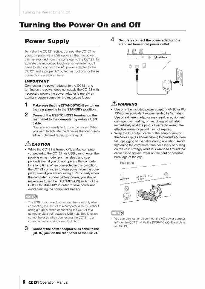
3 Connect the power adaptor’s DC cable to the [DC IN] jack on the rear panel of the CC121.
4 Securely connect the power adaptor to a standard household power outlet.
WARNING• Use only the included power adaptor (PA-3C or PA-
130) or an equivalent recommended by Yamaha). Use of a different adaptor may result in equipment damage, overheating, or fire. Doing so will also immediately void the product warranty, even if the effective warranty period has not expired.
• Wrap the DC output cable of the adaptor around the cable clip (as shown below) to prevent acciden-tal unplugging of the cable during operation. Avoid tightening the cord more than necessary or pulling on the cord strongly while it is wrapped around the cable clip to prevent wear on the cord or possible breakage of the clip.
NOTE
· You can connect or disconnect the AC power adaptor to/from the CC121 while the [STANDBY/ON] switch is set to ON.
Rear panel
8 Operation Manual
Turning the Power On and Off
EN
GLIS
H
Turning the Power On and Off
1 To supply the power actually from the con-nected host computer, press the [STANDBY/ON] switch on the rear panel to set it to the ON position.
2 To cancel the power supply from the con-nected host computer, press the [STANDBY/ON] switch to set it to the STANDBY posi-tion.
CAUTION• Note that a small amount of current continues to
flow while the switch is in the STANDBY position. If you do not plan to use the CC121 for an extended period of time, please be sure to unplug the adap-tor from the wall outlet.
• As soon as you turn off the power of the computer connected to the CC121, make sure to press the [STANDBY/ON] switch of the CC121 to set it to the STANDBY position.
Precautions when using the USB TO HOST terminalWhen connecting the computer to the USB TO HOST terminal, make sure to observe the follow-ing cautions. Failing to do so risks freezing the computer and corrupting or even losing the data. If the computer or the device freezes, restart the application software or the computer OS, or turn the power to the device off then on again.
CAUTION• Use an AB type USB cable of 1.5 meters or
less.• Before connecting the computer to the USB
TO HOST terminal, exit from any power-saving mode of the computer (such as suspended, sleep, standby).
• Before turning on the power to the device, connect the computer to the USB TO HOST terminal.
• Quit any open application software on the com-puter before turning the power to the device on/off or plugging/unplugging the USB cable to/from the USB TO HOST terminal.
• While a USB device is connected to the device, you should wait for six seconds or more between these operations: (1) when turning the power of the device off then on again, or (2) when alternately connecting/dis-connecting the USB cable.
Operation Manual 9
Software Installation
Software InstallationTo use the CC121 you must first install the software on the computer. This section explains the software installation. Install Cubase AI before you install TOOLS for CC121.
NOTE
· If you have already installed a version of Cubase that is compatible with operation with the CC121 (page 15), the instructions on installing Cubase AI described below are not necessary. Jump to the next section “Installing TOOLS for CC121.”
Installing Cubase AI
NOTE
· You are only permitted to use this software pursuant to the terms and conditions of the “Steinberg Software End User License Agreement (EULA)” shown during the installation.
· In order to have continuous use of Cubase AI, including support and other benefits, you will need to register the soft-ware and activate your software license by starting it while the computer is connected to the Internet. Click the “Regis-ter Now” button shown when the software is started, then fill in all required fields for registration. If you do not register the software, you will be unable to use it after a limited period of time expires.
1 Start the computer and log on to the Admin-istrator account.
2 Insert the Cubase AI DVD-ROM into the DVD-ROM drive.
3 When the “WELCOME TO CUBASE AI” win-dow appears, choose your preferred lan-guage by clicking on the corresponding national flag icon.
NOTE
· If this window does not appear automatically, open the DVD-ROM then double-click the file “Start Center.”
4 Follow the onscreen instructions to install the software.
Installing TOOLS for CC121
TOOLS for CC121 consists of two software components:USB-MIDI Driver and Steinberg CC121 Extension. In par-ticular, you should install the USB-MIDI Driver to enable proper communication between the CC121 and your com-puter. You should also install Steinberg CC121 Extension to ensure optimum control over Cubase. The TOOLS for CC121 Installer installs these two software components.
NOTE
· You are only permitted to use this software pursuant to the terms and conditions of the “License Agreement” shown dur-ing the installation.
■ Windows XP:
Preparing to install
1 Make sure that the [STANDBY/ON] switch of the CC121 is in the STANDBY ( ) position.
2 Disconnect all the devices other than the mouse and keyboard from the computer, then connect the CC121 directly to the com-puter (without using a hub) by using a USB cable.
3 Start the computer and log on to the Admin-istrator account.Exit any open applications and close all open windows.
4 Select [Start] (➝ [Settings]) ➝ [Control Panel], click “Switch to Classic View” in the upper left of the window.
5 Go to [System] ➝ [Hardware] ➝ [Driver Signing] ➝ [Driver Signing Options], and select the radio button to the left of “Ignore - Install the software anyway and don’t ask for my approval” and click [OK].
NOTE
· After completing the installation, make sure to restore the original settings if necessary.
6 Close the System Properties window and Control Panel by clicking [OK] or the Close button ([X]) of the windows.
10 Operation Manual

Software InstallationE
NG
LISH
7 Insert the TOOLS for CC121 CD-ROM intothe CD-ROM drive.
Installation
The installer will install the following two software components to your computer.· USB-MIDI Driver· Steinberg CC121 Extension
NOTE
· Use the Cancel button or Close button to quit the installation. Quitting by using the [Ctrl]+[Alt]+[Delete] buttons or by turning off the power while installation is in process can result in problems since the installation is terminated without performing a proper uninstall.
8 After the downloaded compressed file is properly extracted, double-click the file “setup.exe.”The “Welcome to the InstallShield Wizard for TOOLS for CC121” window appears.
9 Click [Next].
10 Follow the on-screen instructions in the Setup window for USB-MIDI Driver and Steinberg CC121 Extension appearing in order.
NOTE
· If the same or new version of Steinberg CC121 Exten-sion has already been installed in your computer, the installation window of the corresponding software will not appear.
· If a message “The software you are installing has not passed Windows Logo Testing” appears, click [Con-tinue Anyway]. You do not need to abort the installa-tion. If the message does not appear, proceed to the next step.
11 When installation is complete, a message indicating so appears. If restarting of the computer is necessary following successful completion of the installation, make sure that the radio button to the left of “Yes, I want to restart my computer now” is selected, then click [Finish] to restart the computer. If restarting the computer is unnecessary, click [Finish] to exit the instal-lation process.
12 Press the [STANDBY/ON] switch of the CC121 to set it to the ON position. The “Found New Hardware Wizard” window appears.
NOTE
· Some computers may take a while to display the Wiz-ard window.
· A dialog box may appear asking you whether you wish to connect to Windows Update. In this case, select the radio button to the left of “Not at this time,” then click [Next].
13 Select the radio button next to “Install the software automatically” then click [Next]. This operation starts the USB-MIDI driver’s installation.
NOTE
· If a message “The software you are installing has not passed Windows Logo Testing” appears, click [Con-tinue Anyway]. You do not need to abort the installa-tion. If the message does not appear, proceed to the next step.
14 When a message indicating installation is complete appears, click [Finish].
This completes installation of the necessary soft-ware.
Uninstallation
To uninstall TOOLS for CC121, you must remove the following two software components:· USB-MIDI Driver· Steinberg CC121 Extension
1 Disconnect all other USB devices except mouse and keyboard from the computer.
2 Log on to the Administrator account.Exit any open applications and close all open windows.
3 From the Start menu, select ([Settings] ➝) [Control Panel] ➝ [Add or Remove Pro-grams] to display the Add or Remove Pro-grams panel.
4 Click “Change or Remove Programs” located in the upper left, then select “Yamaha USB-MIDI Driver”/ “Steinberg CC121 Extension” from the list in the right panel.
5 To uninstall the software, click [Change/Remove]/ [Remove]. A dialog box appears. Follow the on-screen instructions to remove the software.
Operation Manual 11

Software Installation
■ Windows Vista/Windows 7:
Preparing to install
1 Make sure that the [STANDBY/ON] switch of the CC121 is in the STANDBY ( ) position.
2 Disconnect all the devices other than the mouse and keyboard from the computer, then connect the CC121 directly to the com-puter (without using a hub) by using a USB cable.
3 Start the computer and log on to the Admin-istrator account.Exit any open applications and close all open windows.
4 Insert the TOOLS for CC121 CD-ROM into the CD-ROM drive.
Installation
The installer will install the following two software components to your computer.· USB-MIDI Driver· Steinberg CC121 Extension
NOTE
· Use the Cancel button or Close button to quit the installation. Quitting by using the [Ctrl]+[Alt]+[Delete] buttons or by turning off the power while installation is in process can result in problems since the installation is terminated without performing a proper uninstall.
5 After the downloaded compressed file is properly extracted, double-click the file “setup.exe.”The “Welcome to the InstallShield Wizard for TOOLS for CC121” window appears.
NOTE
· If the “User Account Control” window appears, click [Continue].
6 Click [Next].
7 Follow the on-screen instructions in the Setup window for USB-MIDI Driver and Steinberg CC121 Extension appearing in order.
NOTE
· If the same or new version of Steinberg CC121 Exten-sion has already been installed in your computer, the installation window of the corresponding software will not appear.
· If the “Windows Security” window appears, confirm that the publisher is “YAMAHA CORPORATION,” then click [Install].
8 When installation is complete, a message indicating so appears. If restarting of the computer is necessary following successful completion of the installation, make sure that the radio button to the left of “Yes, I want to restart my computer now” is selected, then click [Finish] to restart the computer. If restarting the computer is unnecessary, click [Finish] to exit the instal-lation process.
9 Press the [STANDBY/ON] switch of the CC121 to set it to the ON position. The USB-MIDI Driver is installed automatically.
This completes installation of the necessary soft-ware.
Uninstallation
To uninstall TOOLS for CC121, you must remove the following two software components:· USB-MIDI Driver· Steinberg CC121 Extension
1 Disconnect all other USB devices except mouse and keyboard from the computer.
2 Log on to the Administrator account.Exit any open applications and close all open windows.
3 From the Start menu, select [Control Panel] ➝ [Programs and Features] to call up the “Uninstall or change a program” panel.
4 Select the “Yamaha USB-MIDI Driver”/ “Steinberg CC121 Extension.”
5 Click the [Uninstall]/[Uninstall/Change].Follow the on-screen instructions to remove the software.
NOTE
· If the “User Account Control“ window appears, click [Continue].
12 Operation Manual

Software InstallationE
NG
LISH
■ Mac:Preparing to install
1 Make sure that the [STANDBY/ON] switch of the CC121 is in the STANDBY ( ) position.
2 Disconnect all the devices other than the mouse and keyboard from the computer, then connect the CC121 directly to the com-puter (without using a hub) by using a USB cable.
3 Start the computer and log on to the Admin-istrator account. Exit any open applications and close all open windows.
4 Insert the TOOLS for CC121 CD-ROM into the CD-ROM drive.
Installation
5 After the downloaded compressed file is properly extracted, double-click the file “TOOLS for CC121.mpkg.”The “Welcome to the TOOLS for CC121 Installer” window appears.
NOTE
· If a dialog box appears asking if you want to install the software, click [Continue].
6 Execute the installation by following the on-screen directions.
NOTE
· Only the boot disk can be selected for the installer.
7 When a message appears indicating that the installation is complete, click [Close].
This completes installation of the necessary soft-ware.
Uninstallation
Remove the following files from the boot disk (gener-ally Macintosh HD) to uninstall TOOLS for CC121 (USB-MIDI Driver and Steinberg CC121 Extension.)
NOTE
· If the folders described below are not displayed in the Finder, select [Go to Folder…] under the [Go] menu of the Finder, input the folder locations, and then click [Go].
/Users/“User name” /Library/Preferences/jp.co.yamaha.USBMIDIDriver.plist(This file is created after the driver is loaded.)
/Library/Audio/MIDI Drivers/YAMAHA-USBMIDIDriver.plugin
/Library/PreferencePanes/YAMAHA-USBMIDIPatch.prefPane
/Library/Receipts/YAMAHA-USBMIDIDriver.pkgYAMAHA-USBMIDIPatch.pkg
NOTE
· “User name” applies to the account name that you are using.
· Only the administrator can delete the driver. Normal users do not have the authority to delete.
/Library/Application Support/Steinberg/Componentscc121_extension_u.bundle
/Library/Receipts/Steinberg CC121 Extension.pkg
Removing USB-MIDI driver
Removing Steinberg CC121 Extension
Operation Manual 13
Starting the CC121 and Cubase
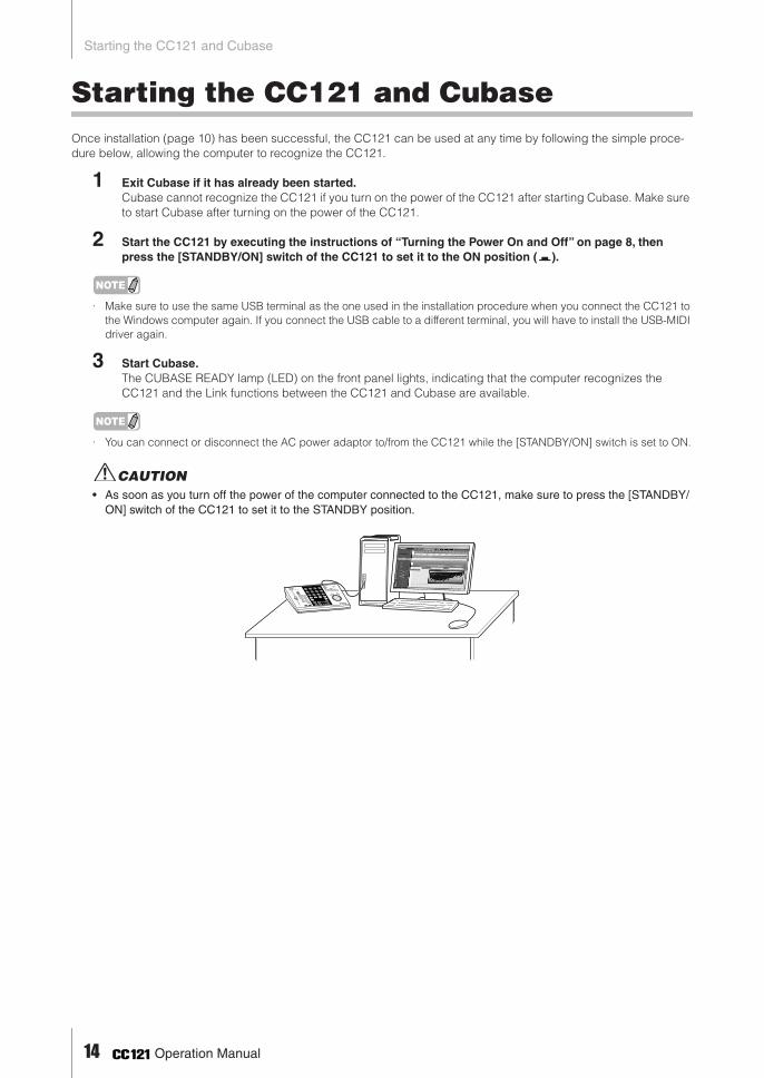
Starting the CC121 and CubaseOnce installation (page 10) has been successful, the CC121 can be used at any time by following the simple proce-dure below, allowing the computer to recognize the CC121.
1 Exit Cubase if it has already been started. Cubase cannot recognize the CC121 if you turn on the power of the CC121 after starting Cubase. Make sure to start Cubase after turning on the power of the CC121.
2 Start the CC121 by executing the instructions of “Turning the Power On and Off” on page 8, then press the [STANDBY/ON] switch of the CC121 to set it to the ON position ( ).
NOTE
· Make sure to use the same USB terminal as the one used in the installation procedure when you connect the CC121 to the Windows computer again. If you connect the USB cable to a different terminal, you will have to install the USB-MIDI driver again.
3 Start Cubase. The CUBASE READY lamp (LED) on the front panel lights, indicating that the computer recognizes the CC121 and the Link functions between the CC121 and Cubase are available.
NOTE
· You can connect or disconnect the AC power adaptor to/from the CC121 while the [STANDBY/ON] switch is set to ON.
CAUTION• As soon as you turn off the power of the computer connected to the CC121, make sure to press the [STANDBY/
ON] switch of the CC121 to set it to the STANDBY position.
14 Operation Manual

The Controls and ConnectorsE
NG
LISH
The Controls and ConnectorsFront Panel
■ CUBASE READY lamp
This LED lamp indicates whether the CC121 is turned on or not and whether communication between the CC121 and the computer is enabled or not. This lamp flashes to indicate that the CC121 is bus-powered from the connected computer. When the lamp is lit continuously, communication with the computer is enabled and Link functions are avail-able.
IMPORTANTTo use the Link function between the CC121 and Cubase, you will need to install Cubase/Cubase AI version 5 or higher. For details, refer to the following website.
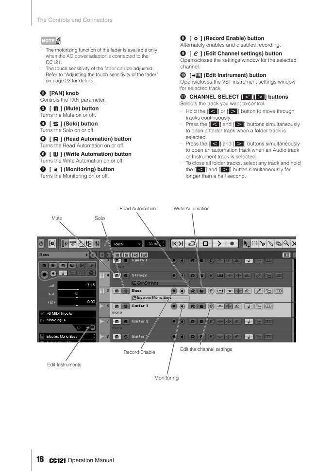
■ Channel sections
This section lets you control the track selected on Cubase. When the Read Automation is turned on, the events generated via the operations in this sec-tion will be recorded to the current track on Cubase.
1 FaderThis 100 mm touch-sensitive motorized fader lets you control the mixer fader of the current track on Cubase.
Channel sections (page 15) EQ sections (page 17) Function section (page 19)
AI KNOB section (page 21)Transport section (page 19)
CUBASE READY lamp (page 15)
http://service.steinberg.de/goto.nsf/show/supportupdates_cc121_gb
37
8
9
)
!
4
5
6
2
1
Operation Manual 15
The Controls and Connectors
NOTE
· The motorizing function of the fader is available only when the AC power adaptor is connected to the CC121.
· The touch sensitivity of the fader can be adjusted. Refer to “Adjusting the touch sensitivity of the fader” on page 23 for details.
2 [PAN] knobControls the PAN parameter.
3 [ ] (Mute) buttonTurns the Mute on or off.
4 [ ] (Solo) buttonTurns the Solo on or off.
5 [ ] (Read Automation) buttonTurns the Read Automation on or off.
6 [ ] (Write Automation) buttonTurns the Write Automation on or off.
7 [ ] (Monitoring) buttonTurns the Monitoring on or off.
8 [ ] (Record Enable) buttonAlternately enables and disables recording.
9 [ ] (Edit Channel settings) buttonOpens/closes the settings window for the selected channel.
) [ ] (Edit Instrument) buttonOpens/closes the VST instrument settings window for selected track.
! CHANNEL SELECT [ ][ ] buttonsSelects the track you want to control.
· Hold the [ ] or [ ] button to move through tracks continuously.
· Press the [ ] and [ ] buttons simultaneously to open a folder track when a folder track is selected.
· Press the [ ] and [ ] buttons simultaneously to open an automation track when an Audio track or Instrument track is selected.
· To close all folder tracks, select any track and hold the [ ] and [ ] button simultaneously for longer than a half second.
Mute Solo
Read Automation
Edit the channel settings
Monitoring
Record Enable
Edit Instruments
Write Automation
16 Operation Manual

The Controls and ConnectorsE
NG
LISH
■ EQ sectionsThe functions of the EQ section differ according to the mode: Normal, Selecting EQ TYPE, and Operat-ing Quick Control. Refer to the following table for explanations of the function in each mode.
Normal mode
This mode lets you adjust the parameters of the 4-band EQ built into the Audio track or Instrument track.
1 [Q] knobs
Adjusts the Q (bandwidth) of each EQ band.
2 [F] (Frequency) knobs
Adjusts the center frequency of each EQ band.
3 [G] (Gain) knobs
Adjusts the gain of each EQ band.
4 [ON] button
Turns each EQ band on or off.
5 [EQ TYPE] button
Enters the Selecting EQ TYPE mode. Refer to the “Selecting EQ TYPE mode” for details.
6 [ALL BYPASS] button
Turns EQ bypass on or off.
1
2
3
4
5 6
Operation Manual 17
The Controls and Connectors
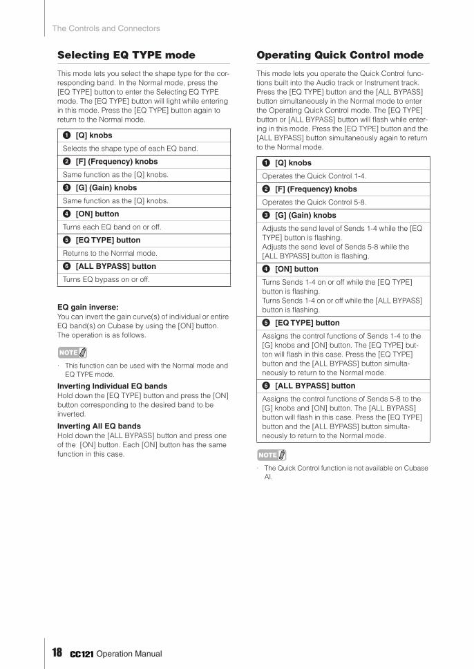
Selecting EQ TYPE mode
This mode lets you select the shape type for the cor-responding band. In the Normal mode, press the [EQ TYPE] button to enter the Selecting EQ TYPE mode. The [EQ TYPE] button will light while entering in this mode. Press the [EQ TYPE] button again to return to the Normal mode.
EQ gain inverse:You can invert the gain curve(s) of individual or entire EQ band(s) on Cubase by using the [ON] button. The operation is as follows.
NOTE
· This function can be used with the Normal mode and EQ TYPE mode.
Inverting Individual EQ bandsHold down the [EQ TYPE] button and press the [ON] button corresponding to the desired band to be inverted.
Inverting All EQ bandsHold down the [ALL BYPASS] button and press one of the [ON] button. Each [ON] button has the same function in this case.
Operating Quick Control mode
This mode lets you operate the Quick Control func-tions built into the Audio track or Instrument track. Press the [EQ TYPE] button and the [ALL BYPASS] button simultaneously in the Normal mode to enter the Operating Quick Control mode. The [EQ TYPE] button or [ALL BYPASS] button will flash while enter-ing in this mode. Press the [EQ TYPE] button and the [ALL BYPASS] button simultaneously again to return to the Normal mode.
NOTE
· The Quick Control function is not available on Cubase AI.
1 [Q] knobs
Selects the shape type of each EQ band.
2 [F] (Frequency) knobs
Same function as the [Q] knobs.
3 [G] (Gain) knobs
Same function as the [Q] knobs.
4 [ON] button
Turns each EQ band on or off.
5 [EQ TYPE] button
Returns to the Normal mode.
6 [ALL BYPASS] button
Turns EQ bypass on or off.
1 [Q] knobs
Operates the Quick Control 1-4.
2 [F] (Frequency) knobs
Operates the Quick Control 5-8.
3 [G] (Gain) knobs
Adjusts the send level of Sends 1-4 while the [EQ TYPE] button is flashing. Adjusts the send level of Sends 5-8 while the [ALL BYPASS] button is flashing.
4 [ON] button
Turns Sends 1-4 on or off while the [EQ TYPE] button is flashing.Turns Sends 1-4 on or off while the [ALL BYPASS] button is flashing.
5 [EQ TYPE] button
Assigns the control functions of Sends 1-4 to the [G] knobs and [ON] button. The [EQ TYPE] but-ton will flash in this case. Press the [EQ TYPE] button and the [ALL BYPASS] button simulta-neously to return to the Normal mode.
6 [ALL BYPASS] button
Assigns the control functions of Sends 5-8 to the [G] knobs and [ON] button. The [ALL BYPASS] button will flash in this case. Press the [EQ TYPE] button and the [ALL BYPASS] button simulta-neously to return to the Normal mode.
18 Operation Manual
The Controls and Connectors
EN
GLIS
H
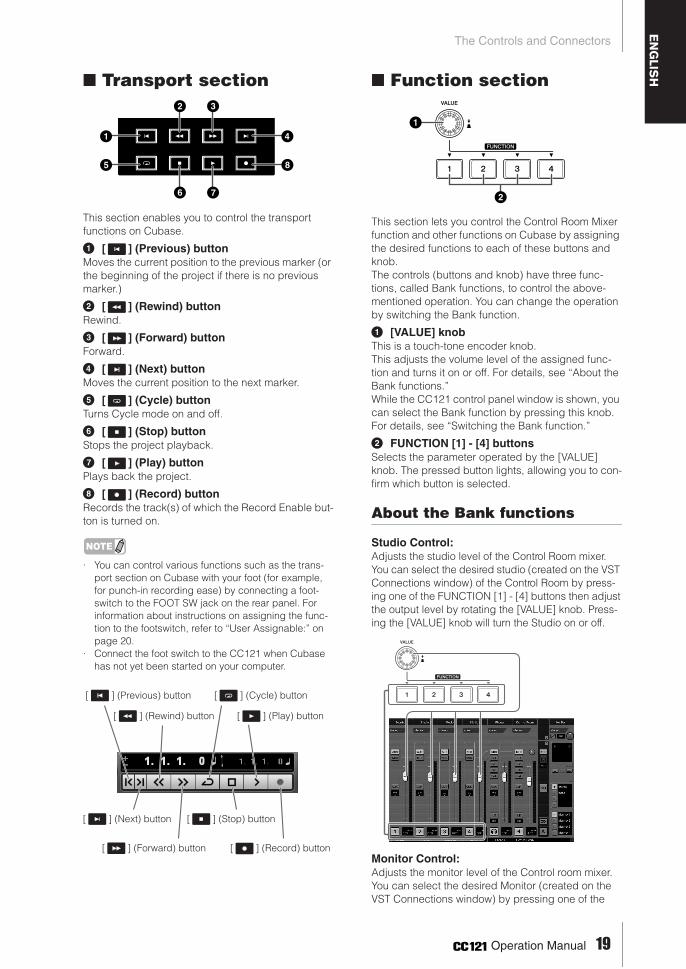
■ Transport section
This section enables you to control the transport functions on Cubase.
1 [ ] (Previous) buttonMoves the current position to the previous marker (or the beginning of the project if there is no previous marker.)
2 [ ] (Rewind) buttonRewind.
3 [ ] (Forward) buttonForward.
4 [ ] (Next) buttonMoves the current position to the next marker.
5 [ ] (Cycle) buttonTurns Cycle mode on and off.
6 [ ] (Stop) buttonStops the project playback.
7 [ ] (Play) buttonPlays back the project.
8 [ ] (Record) buttonRecords the track(s) of which the Record Enable but-ton is turned on.
NOTE
· You can control various functions such as the trans-port section on Cubase with your foot (for example, for punch-in recording ease) by connecting a foot-switch to the FOOT SW jack on the rear panel. For information about instructions on assigning the func-tion to the footswitch, refer to “User Assignable:” on page 20.
· Connect the foot switch to the CC121 when Cubase has not yet been started on your computer.
■ Function section
This section lets you control the Control Room Mixer function and other functions on Cubase by assigning the desired functions to each of these buttons and knob.The controls (buttons and knob) have three func-tions, called Bank functions, to control the above-mentioned operation. You can change the operation by switching the Bank function.
1 [VALUE] knobThis is a touch-tone encoder knob.This adjusts the volume level of the assigned func-tion and turns it on or off. For details, see “About the Bank functions.”While the CC121 control panel window is shown, you can select the Bank function by pressing this knob. For details, see “Switching the Bank function.”
2 FUNCTION [1] - [4] buttonsSelects the parameter operated by the [VALUE] knob. The pressed button lights, allowing you to con-firm which button is selected.
About the Bank functions
Studio Control: Adjusts the studio level of the Control Room mixer.You can select the desired studio (created on the VST Connections window) of the Control Room by press-ing one of the FUNCTION [1] - [4] buttons then adjust the output level by rotating the [VALUE] knob. Press-ing the [VALUE] knob will turn the Studio on or off.
Monitor Control: Adjusts the monitor level of the Control room mixer.You can select the desired Monitor (created on the VST Connections window) by pressing one of the
1
2 3
6 7
5
4
8
[ ] (Previous) button [ ] (Cycle) button
[ ] (Rewind) button [ ] (Play) button
[ ] (Next) button
[ ] (Forward) button
[ ] (Stop) button
[ ] (Record) button
1
2
Operation Manual 19

The Controls and Connectors
FUNCTION [1] - [4] buttons then adjust the monitor output level by rotating the [VALUE] knob. Pressing the [VALUE] knob will turn the Control Room’s output on or off.
User Assignable:You can freely assign desired parameters of Cubase to the [VALUE] knob, FUNCTION [1] - [4] buttons and foot switch connected to the FOOT SW jack (page 22). The parameter assignment can be per-formed in the Device Setup window (called up via [Device Setup...] under the [Devices] menu.) After selecting “Steinberg CC121” under “Remote Devices” in the Devices box, set 1 and 3 displayed (see below.)
1 User CommandsSelect the desired function for the FUNCTION [1] - [4] buttons (“Fnuction1” - “Function4”) and foot switch connected to the FOOT SW jack by clicking the “Category” column and “Command” column.
2 ResetResets all settings of “User Commands” (1) to default setting.
3 Custom AssignmentSet the desired function to the [VALUE] knob. The following four values can be set.
NOTE
· If you are using Cubase AI, which does not feature the Control Room function, only “User Assignable” func-tion is available from the above three function sets.
Switching the Bank function
You can switch the Bank function using the [VALUE] knob. The operation is as follows.
1 Hold down the [JOG] button to call up the CC121 control panel window.When the window appears, release the [JOG] button.CC121 control panel window
2 Press the [VALUE] knob to select “Bank.”
3 Press the [VALUE] knob again to switch the Bank function.
4 Hold down the [JOG] button to close the CC121 control panel window.When the window closes, release the [JOG] button.
NOTE
· The Bank functions can also be selected from the Device Setup window (called up via [Device Setup...] under the [Devices] menu) on Cubase. From this win-dow, select “Steinberg CC121” under “Remote Devices” in the Devices box, then select a desired Bank function at the “Bank” column at the bottom right corner of the window.
Metronome Level:
Rotating the [VALUE] knob adjusts the output level of metronome sound. Pressing the [VALUE] knob switches the metronome sound on/off.
3
1
2
Main Mix Volume:
Rotating the [VALUE] knob adjusts the output level of main output. Pressing the [VALUE] knob switches the mute on/off.
CR Volume:
Rotating the [VALUE] knob adjusts the Monitor output level of the Control Room Mixer. Pressing the [VALUE] knob alternately enables/disables the Monitor output. This value is available only for the flagship model of Cubase.
CR Phones:
Rotating the [VALUE] knob adjusts the Phones output level of the Control Room Mixer. Pressing the [VALUE] knob alternately enables/disables the Phones output. This value is available only for the flagship model of Cubase.
Bank functions
20 Operation Manual

The Controls and ConnectorsE
NG
LISH
■ AI KNOB sectionThis section lets you con-trol a desired parameter specified via the mouse pointer and moving the current position of the project.1 AI KNOBThis multi-function knob can control a desired parameter within the principal window and plug-in software on Cubase, specified via the mouse pointer (as long as the [LOCK] button and [JOG] button are turned off). The assignable parameters to the AI KNOB change according to the on/off status of the [LOCK] button and [JOG] button.
NOTE
· The assignable parameters to the AI KNOB are parameters that can be automated within the principal window and plug-in software on Cubase. Plug-in soft-ware compatible with the AI KNOB are the VST 3 plug-ins included with Cubase (as of November 2011.) For the latest information about compatible plug-in software, refer to the following URL:http://service.steinberg.de/goto.nsf/show/supportupdates_cc121_gb
2 [LOCK] buttonYou can “lock” the parameter to be edited via the AI KNOB by turning this button on. When you locate the mouse pointer to the desired parameter then turn the [LOCK] button on, the AI KNOB will control the “locked” parameter regardless of the mouse pointer’s position. By turning the [LOCK] button off, you can unlock the parameter to be edited and the AI KNOB can then be used to edit another parameter to which the mouse pointer is located.
3 [JOG] buttonTurns functions which are controlled by the AI KNOB on or off. You can choose the functions from among “Jog,” “Shuttle” and “Scrub.”Hold down this button to switch the CC121 control panel window. Pressing this again after the CC121 control panel window appears will switch the func-tion settings (Jog Mode settings).
The name and feature of the Jog Mode settings are as follows;
Jog:Controls the “time position slider” on Cubase. Turn-ing the [LOCK] button on after selecting this setting will continue moving the time position slider even if you release the AI KNOB after rotating. The current position appears on the time position slider.
Shuttle:Works as the “Shuttle speed” function on Cubase. Audio is played back while operating this function.
Scrub:Works as the “Jog wheel” function on Cubase. Audio is played back while operating this function.You can adjust the Jog wheel speed by the pull-down menu on the right side. The larger the number, the faster the speed.
1
2 3
Adjusting the parameter to which the mouse pointer is located
Locking the parameter to be edited
Editing the “locked” parameter regardless of the mouse pointer’s location
Jog Mode settings
CC121 control panel window
Time position slider
Operation Manual 21
The Controls and Connectors
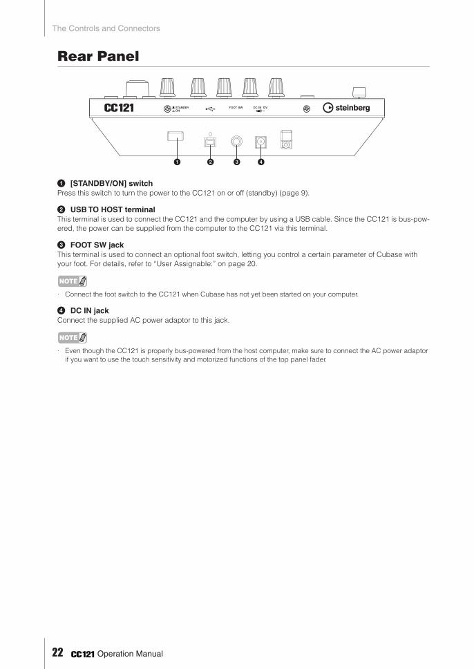
Rear Panel
1 [STANDBY/ON] switchPress this switch to turn the power to the CC121 on or off (standby) (page 9).
2 USB TO HOST terminalThis terminal is used to connect the CC121 and the computer by using a USB cable. Since the CC121 is bus-pow-ered, the power can be supplied from the computer to the CC121 via this terminal.
3 FOOT SW jackThis terminal is used to connect an optional foot switch, letting you control a certain parameter of Cubase with your foot. For details, refer to “User Assignable:” on page 20.
NOTE
· Connect the foot switch to the CC121 when Cubase has not yet been started on your computer.
4 DC IN jackConnect the supplied AC power adaptor to this jack.
NOTE
· Even though the CC121 is properly bus-powered from the host computer, make sure to connect the AC power adaptor if you want to use the touch sensitivity and motorized functions of the top panel fader.
1 2 3 4
22 Operation Manual

Adjusting the touch sensitivity of the faderE
NG
LISH
Adjusting the touch sensitivity of thefaderYou can adjust the touch sensitivity of the fader over a range from 1 to 8.
1 Press the [STANDBY/ON] switch of the CC121 to set it to the STANDBY ( ) posi-tion, then connect the CC121 to the com-puter via a USB cable.
2 Start the computer.
3 Press the [STANDBY/ON] switch to set it the ON position while holding the CHANNEL SELECT [ ] button and CHANNEL SELECT [ ] button.Hold the CHANNEL SELECT [ ] and [ ] buttons continuously.All of LEDs on the CC121 will light briefly, then some LEDs will light. (This indicates the version of the CC121 firmware.)
4 When some LEDs light on the CC121, release the CHANNEL SELECT [ ] and [ ] buttons.The CUBASE READY lamp will flash and the current setting of the touch sensitivity is indi-cated by the on/off status of the eight buttons (show below) in the Channel section. When the touch sensitivity is set to 2, for example, the [ ] (Read Automation) button and [ ] (Edit Instrument) button are turned on.
5 Press the button corresponding to the desired sensitivity, following the list below. A setting of “1” produces the most gradual response while a setting of “8” produces the most sensitive response.
Pressing the button will set the touch sensitivity, turn on the lamps of the pressed button and all buttons representing values below, then store the specified value to the internal memory of the CC121.
6 Confirm the result of the setting by touching the fader. The lamp of the [ ] (Record) button of the Transport section will light as soon as the CC121 recognizes that the fader is operated.
7 Repeat steps 4 - 5 to adjust the sensitivity.
8 After finishing the setting, press the [STANDBY/ON] switch to set it to the STANDBY position.
Now the setting is complete.
Lighting of these two buttons only indicates that the touch sensitivity is set to 2.
Sensitivity Button
8 [ ] (Mute) button
7 [ ] (Monitor) button
6 [ ] (Solo) button
5 [ ] (Enable Record) button
4 [ ] (Read Enable) button
3 [ ] (Channel Settings) button
2 [ ] (Write Enable) button
1 [ ] (Edit Instrument) button
Touch sensitivity 8
Touch sensitivity 6
Touch sensitivity 4
Touch sensitivity 2
Touch sensitivity 7
Touch sensitivity 5
Touch sensitivity 3
Touch sensitivity 1
Operation Manual 23

Troubleshooting
Troubleshooting■ The power of the instrument does not
turn on.· Make sure that the CC121 is properly connected
to the computer via a USB cable. The USB bus-power is necessary to use the CC121. The AC power adaptor is used as the auxiliary power sup-ply for driving the motorized fader and cannot supply enough power necessary for using the CC121 as a controller for Cubase.
· Confirm whether or not a proper USB cable is used. If the USB cable is broken or damaged, have the USB cable replaced with a known work-ing one. Use a USB cable no longer than 1.5 meters.
· Confirm whether not the USB hub with the bus-powered type is used for connecting the CC121 and computer. If you must use USB hub, use the self-powered type.
■ Cubase does not recognize the CC121.· Make sure that the CC121 is properly connected
to the computer via a USB cable. · Confirm whether or not a proper USB cable is
used. If the USB cable is broken or damaged, have the USB cable replaced with a known work-ing one. Use a USB cable no longer than 1.5 meters.
· Confirm whether or not the CC121 is turned on before starting Cubase. If not, do so.
· Make sure that the USB-MIDI driver and Steinberg CC121 Extension has been installed.
· (Windows XP only) Make sure the “Use Device Name As Port Name” box is checked in the MIDI patch window (called up by selecting [Start] ➝ [Control Panel] ➝ [Yamaha USB-MIDI Driver]).
· Make sure that CC121 is selected as the port set-ting on Cubase. The port is described in the Device Setup window (called up via [Device Setup...] under the [Devices] menu) when select-ing “Steinberg CC121” under “Remote Devices” in the Devices box.
· Confirm whether or not the Remote Control set-tings on Cubase are proper. Refer to the manual of Cubase.
■ Cannot control Cubase even if you operate the fader of the CC121· Confirm whether or not the touch sensitivity of the
fader is proper. Adjust the touch sensitivity (page 23).
■ The motorized fader does not work· Confirm whether or not the AC power adaptor is
connected. The power supply via the AC power adaptor is necessary for driving the motorized fader as well as bus-power from the host com-puter.
· Confirm whether or not the touch sensitivity of the fader is proper. Excessive settings of the touch sensitivity may cause unexpected stopping of the fader even if you do not touch it. Adjust the touch sensitivity (page 23).
Specifications
* Specifications and descriptions in this manual are for information purposes only. Steinberg/Yamaha Corp. reserves the right to change or modify products or specifications at any time without prior notice. Since specifi-cations, equipment or options may not be the same in every locale, please check with your Steinberg/Yamaha dealer.
Connectors USB TO HOST terminal, FOOT SW jack, DC IN jack
Power Supply USB bus-powered: 5V/500mAPower adaptor (for driving the motorized fader): PA-3C, PA-130 or equivalent recommended by Yamaha
Power Consumption USB bus-powered: 1.5WPower adaptor (for driving the motorized fader): 5W
Dimensions 284 x 72 x 185 mm (W x H x D)
Weight 1.5kg
Accessories Power adaptor (PA-3C, PA-130 or equivalent), USB cable, CD-ROM (TOOLS for CC121), DVD-ROM (Cubase AI), Operation Manual (this book)
24 Operation Manual
(weee_eu)
Information for Users on Collection and Disposal of Old Equipment
This symbol on the products, packaging, and/or accompanying documents means that used electrical and electronic products should not be mixed with general household waste.For proper treatment, recovery and recycling of old products, please take them to applicable collection points, in accordance with your national legislation and the Directives 2002/96/EC.By disposing of these products correctly, you will help to save valuable resources and prevent any potential negative effects on human health and the environment which could otherwise arise from inappropriate waste handling.For more information about collection and recycling of old products, please contact your local municipality, your waste disposal service or the point of sale where you purchased the items.
[For business users in the European Union]If you wish to discard electrical and electronic equipment, please contact your dealer or supplier for further information.
[Information on Disposal in other Countries outside the European Union]This symbol is only valid in the European Union. If you wish to discard these items, please contact your local authorities or dealer and ask for the correct method of disposal.
Verbraucherinformation zur Sammlung und Entsorgung alter Elektrogeräte
Befindet sich dieses Symbol auf den Produkten, der Verpackung und/oder beiliegenden Unterlagen, so sollten benutzte elektrische Geräte nicht mit dem normalen Haushaltsabfall entsorgt werden.In Übereinstimmung mit Ihren nationalen Bestimmungen und den Richtlinien 2002/96/EC bringen Sie alte Geräte bitte zur fachgerechten Entsorgung, Wiederaufbereitung und Wiederverwendung zu den entsprechenden Sammelstellen.Durch die fachgerechte Entsorgung der Elektrogeräte helfen Sie, wertvolle Ressourcen zu schützen, und verhindern mögliche negative Auswirkungen auf die menschliche Gesundheit und die Umwelt, die andernfalls durch unsachgerechte Müllentsorgung auftreten könnten.Für weitere Informationen zum Sammeln und Wiederaufbereiten alter Elektrogeräte kontaktieren Sie bitte Ihre örtliche Stadt- oder Gemeindeverwaltung, Ihren Abfallentsorgungsdienst oder die Verkaufsstelle der Artikel.
[Information für geschäftliche Anwender in der Europäischen Union]Wenn Sie Elektrogeräte ausrangieren möchten, kontaktieren Sie bitte Ihren Händler oder Zulieferer für weitere Informationen.
[Entsorgungsinformation für Länder außerhalb der Europäischen Union]Dieses Symbol gilt nur innerhalb der Europäischen Union. Wenn Sie solche Artikel ausrangieren möchten, kontaktieren Sie bitte Ihre örtlichen Behörden oder Ihren Händler und fragen Sie nach der sachgerechten Entsorgungsmethode.
Information concernant la Collecte et le Traitement des déchets d’équipements électriques et électroniques.
Le symbole sur les produits, l'emballage et/ou les documents joints signifie que les produits électriques ou électroniques usagés ne doivent pas être mélangés avec les déchets domestiques habituels.Pour un traitement, une récupération et un recyclage appropriés des déchets d’équipements électriques et électroniques, veuillez les déposer aux points de collecte prévus à cet effet, conformément à la réglementation nationale et aux Directives 2002/96/EC.En vous débarrassant correctement des déchets d’équipements électriques et électroniques, vous contribuerez à la sauvegarde de précieuses ressources et à la prévention de potentiels effets négatifs sur la santé humaine qui pourraient advenir lors d'un traitement inapproprié des déchets.Pour plus d'informations à propos de la collecte et du recyclage des déchets d’équipements électriques et électroniques, veuillez contacter votre municipalité, votre service de traitement des déchets ou le point de vente où vous avez acheté les produits.
[Pour les professionnels dans l'Union Européenne]Si vous souhaitez vous débarrasser des déchets d’équipements électriques et électroniques veuillez contacter votre vendeur ou fournisseur pour plus d'informations.
[Information sur le traitement dans d'autres pays en dehors de l'Union Européenne]Ce symbole est seulement valable dans l'Union Européenne. Si vous souhaitez vous débarrasser de déchets d’équipements électriques et électroniques, veuillez contacter les autorités locales ou votre fournisseur et demander la méthode de traitement appropriée.
Información para Usuarios sobre Recolección y Disposición de Equipamiento Viejo
Este símbolo en los productos, embalaje, y/o documentación que se acompañe significa que los productos electrónicos y eléctricos usados no deben ser mezclados con desechos hogareños corrientes.Para el tratamiento, recuperación y reciclado apropiado de los productos viejos, por favor llévelos a puntos de recolección aplicables, de acuerdo a su legislación nacional y las directivas 2002/96/EC.Al disponer de estos productos correctamente, ayudará a ahorrar recursos valiosos y a prevenir cualquier potencial efecto negativo sobre la salud humana y el medio ambiente, el cual podría surgir de un inapropiado manejo de los desechos.Para mayor información sobre recolección y reciclado de productos viejos, por favor contacte a su municipio local, su servicio de gestión de residuos o el punto de venta en el cual usted adquirió los artículos.
[Para usuarios de negocios en la Unión Europea]Si usted desea deshacerse de equipamiento eléctrico y electrónico, por favor contacte a su vendedor o proveedor para mayor información.
[Información sobre la Disposición en otros países fuera de la Unión Europea]Este símbolo sólo es válido en la Unión Europea. Si desea deshacerse de estos artículos, por favor contacte a sus autoridades locales y pregunte por el método correcto de disposición.
EN
DE
FR
ES

►Warranty Terms and Conditions
available as printable PDF file at
www.steinberg.net/warranty
The Warranty Terms and Conditions available as printed PDF file at www.steinberg.net/warranty apply only for countries of the European Economic Area (EEA) and Switzerland.
►Gewährleistungsbestimmungen
finden Sie als druckbare PDF Datei unter
www.steinberg.de/warranty
Die Gewährleistungsbestimmungen in Schriftform sind als PDF-Datei unter www.steinberg.de/warranty erhältlich und gelten nur für den Europäischen Wirtschaftsraum (EWR) und die Schweiz.
►Les conditions de garantie
se trouvent dans le document PDF imprimable sous
www.steinberg.net/warranty
Les conditions de garantie disponibles au format PDF à la page www.steinberg.net/warranty s’appliquent uniquement aux pays de l’Espace économique européen (EEE) et à la Suisse.
►Las condiciones de garantía
se encuentran en el documento PDF en
www.steinberg.net/warranty
Los términos y condiciones de la garantía como archivo PDF para su impresión en www.steinberg.net/ warranty sólo están disponible en países del Espacio Económico Europeo (EEE) y Suiza.
►Termini e Condizioni di Garanzia
disponibili su file PDF stampabile all’indirizzo web
www.steinberg.net/warranty
I termini e le condizioni della garanzia, disponibili in formato PDF all’indirizzo www.steinberg.net/warranty, sono validi soltanto per I paesi dell’Area Economica Europea (EEA) e per la Svizzera.

If you need support or further product information please contact the distributor in your country.A list of distributors is available at this website:http://www.steinberg.net/en/company/distributor.htmlFor assistance in determining who to contact, please contact “Headquarter SMTG.”
Wenn Sie Unterstützung oder weitere Produktinformationen benötigen, wenden Sie sich bitte an den Vertrieb in Ihrem Land.Eine Liste der Vertriebspartner finden Sie auf dieser Website:http://www.steinberg.net/en/company/distributor.htmlWenn Sie Hilfe benötigen, an wen Sie sich wenden sollten, kontaktieren Sie bitte „Headquarter SMTG“.
Pour toute demande d’assistance ou d’information supplémentaire sur les produits, veuillez contacter le distributeur agréé dans votre pays.La liste des distributeurs agréés est disponible sur le site Web suivant :http://www.steinberg.net/en/company/distributor.htmlPour obtenir de l’aide sur les ressources à contacter, adressez-vous au « Siège de SMTG ».
Para solicitar asistencia o más información sobre el producto, póngase en contacto con el distribuidor de su país.Encontrará una lista de distribuidores en el siguiente sitio web:http://www.steinberg.net/en/company/distributor.htmlPara consultas sobre el contacto adecuado, diríjase a “Headquarter SMTG.”
Per ottenere assistenza o avere ulteriori informazioni sul prodotto, contattare il distributore locale.L’elenco dei distributori è disponibile sul sito Web al seguente indirizzo:http://www.steinberg.net/en/company/distributor.htmlPer individuare il distributore da contattare, rivolgersi alla sede centrale SMTG.
如需更多支持和深层产品信息,请联系您所在国家的代理商。
代理商列表请浏览下列网址 :
http://www.steinberg.net/en/company/distributor.html
如需帮助决定联系哪方代理商,请联系 "SMTG 总公司 "。
HEAD OFFICESteinberg Media Technologies GmbH
Frankenstraße 18b, 20097 Hamburg, GermanyTel: +49-(0)40-210 35 0

This document is printed on chlorine free (ECF) paper.
Auf Umweltpapier gedruckt.
Ce document a été imprimé sur du papier non blanchi au chlore.
Este documento se ha impreso en papel sin cloro alguno.
C.S.G., Pro Audio Division© 2008-2011 Yamaha Corporation
111APDH*.*-01D0Printed in Japan
ZA68190
Steinberg Web Sitehttp://www.steinberg.net


![Decision …downloads.hindawi.com/journals/complexity/2020/9602526.pdfcriteria,cangrouppatterns,wheregroupsaresetsofsimilar patterns[54,59,60].Clusteringalgorithms arewidelyap-plied](https://static.fdocuments.in/doc/165x107/5f3f6490fc08093e7c56f69c/decision-criteriacangrouppatternswheregroupsaresetsofsimilar-patterns545960clusteringalgorithms.jpg)


