CC LCD DispLay aneL - AutomationDirect · The DL06 LCD Display Panel is a 16 character, two row...
30
LCD DISPLAY P ANEL 10 10 10 CHAPTER CHAPTER CHAPTER LCD DISPLAY P ANEL 10 10 10 CHAPTER CHAPTER CHAPTER In This Chapter... Introduction to the DL06 LCD Display Panel .................................. 10–2 Keypad........................................................................................... 10–2 Snap-in installation......................................................................... 10–3 Display Priority ............................................................................... 10–4 Menu Navigation ........................................................................... 10–5 Confirm PLC Type, Firmware Revision Level, Memory Usage, Etc... 10–6 Examining Option Slot Contents .................................................... 10–8 Monitoring and Changing Data Values ........................................ 10–10 Bit Monitor .................................................................................. 10–13 Changing Date and Time ............................................................. 10–14 Setting Password and Locking...................................................... 10–17 Reviewing Error History ................................................................ 10–20 Toggle Light and Beeper, Test Keys ............................................. 10–21 PLC Memory Information for the Display ..................................... 10–22 Changing the Default Screen ....................................................... 10–25 DL06 LCD Display Panel Instruction (LCD) ................................... 10–26
-
Upload
dangkhuong -
Category
Documents
-
view
228 -
download
0
Transcript of CC LCD DispLay aneL - AutomationDirect · The DL06 LCD Display Panel is a 16 character, two row...

LCD DispLay paneL 101010ChapterChapterChapter
LCD DispLay paneL 101010ChapterChapterChapter
In This Chapter...Introduction to the DL06 LCD Display Panel .................................. 10–2Keypad ........................................................................................... 10–2Snap-in installation ......................................................................... 10–3Display Priority ............................................................................... 10–4Menu Navigation ........................................................................... 10–5Confirm PLC Type, Firmware Revision Level, Memory Usage, Etc. .. 10–6Examining Option Slot Contents .................................................... 10–8Monitoring and Changing Data Values ........................................ 10–10Bit Monitor .................................................................................. 10–13Changing Date and Time ............................................................. 10–14Setting Password and Locking ...................................................... 10–17Reviewing Error History ................................................................ 10–20Toggle Light and Beeper, Test Keys ............................................. 10–21PLC Memory Information for the Display ..................................... 10–22Changing the Default Screen ....................................................... 10–25DL06 LCD Display Panel Instruction (LCD) ................................... 10–26

DL06 Micro PLC User Manual, 3rd Edition, Rev. E10-2
Chapter 10: LCD Display Panel
1
2
3
4
5
6
7
8
9
10
11
12
13
14
A
B
C
D
Introduction to the DL06 LCD Display PanelThe DL06 LCD Display Panel is a 16 character, two row display that mounts directly on the face of the DL06 PLC. The LCD is backlit for easy readability in most lighting situations. There are multiple ways of interacting with the LCD Display Panel:
• Built-in keypad
• LCD ladder instruction
• Using ladder instructions to write bit status changes to specified memory locations
The seven function keys on the face of the LCD Display Panel give the user access to clock and calendar setup, V-memory data values or I/O status, etc. Individuals with password authorization can:
• Change clock or calendar settings or formats
• Monitor or change V-memory values (including DWord values)
• Force individual bits on or off (up to 16 per screen)
• Review error code history
• Set or change the password
• Turn the back light or buzzer on or off
The potential uses for the DL06’s LCD display vary widely. An operator can change values for setting up batch processes or machine timing for manufacturing different products. Maintenance personnel can interface in the control cabinet to identify machine problems. LCD messages can be preprogrammed for process events or alarms. The LCD can satisfy these and many other needs.
KeypadThe LCD Display Panel keypad has seven keys you can use to navigate through the menu hierarchy. Each screen displayed has a specific set of active keys associated with it. All other keys (those not associated with the current screen) are inactive.
1
2
3
4
5
6
7
8
9
10
11
12
13
14
a
B
C
D
06LOGICKoyo
ESC MENU ENT
Up Right
Down
Menu EnterEscape
LeftFunction Keys
Name Label FunctionUp arrow none Move to selection above or increase value
Down arrow none Move to selection below or decrease valueLeft arrow none Move to next digit to the left
Right arrow none Move to next digit to the right
Escape ESC Return to previous screen or next level up in the menu hierarchy
Menu MENU Scroll down through main menu or sub-menu selections
Enter ENT Enter the domain of the menu screen selected or save new value
DL06 Micro PLC User Manual, 3rd Edition, Rev. E 10-3
Chapter 10: LCD Display Panel
1
2
3
4
5
6
7
8
9
10
11
12
13
14
A
B
C
D
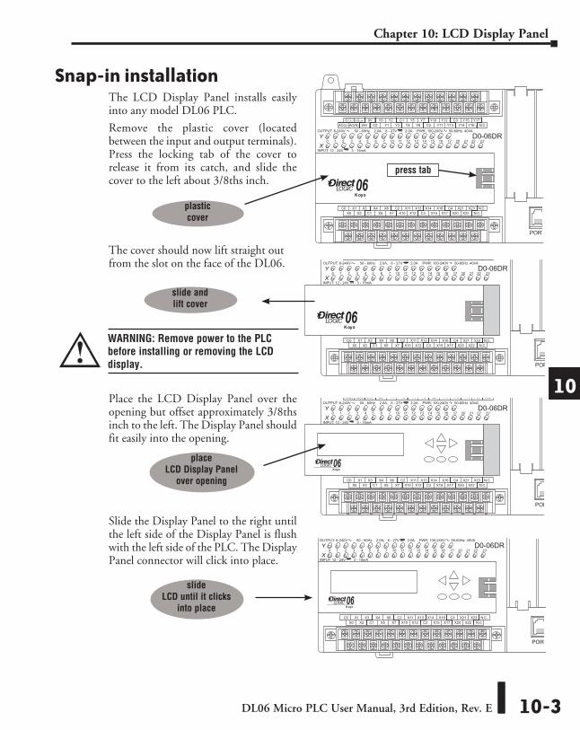
Snap-in installationThe LCD Display Panel installs easily into any model DL06 PLC.
Remove the plastic cover (located between the input and output terminals). Press the locking tab of the cover to release it from its catch, and slide the cover to the left about 3/8ths inch.
The cover should now lift straight out from the slot on the face of the DL06.
Place the LCD Display Panel over the opening but offset approximately 3/8ths inch to the left. The Display Panel should fit easily into the opening.
Slide the Display Panel to the right until the left side of the Display Panel is flush with the left side of the PLC. The Display Panel connector will click into place.
LOGICKoyo06
C0 C4C2X1 X3 X4 X6 X11 X13 X14 X16 X21 X23 N.C.C1 C3X2 X5 X7 X10 X12 X15 X17 X20 X22X0 N.C.
AC(N) 24V0V
N.C.C1 C3Y0 Y15Y12Y10 Y17Y7Y5Y2
C0 C2 Y16Y14Y13Y11Y6Y4Y3Y1LGG
AC(L)
D0-06DR2.0AOUTPUT: 6-240V 50 - 60Hz 2.0A, 6 - 27V
INPUT: 12 - 24V 3 - 15mA
YX
40VA50-60HzPWR: 100-240V
0 1 2 3 4 5 6 7 10 11 12 13 14 15 16 17 20 21 22 23
PORT1 PORT2
TERM
RUN STOP
PWRRUNCPUTX1RX1TX2RX2
06LOGICKoyo
C0 C4C2X1 X3 X4 X6 X11 X13 X14 X16 X21 X23 N.C.C1 C3X2 X5 X7 X10 X12 X15 X17 X20 X22X0 N.C.
AC(N) 24V0V
N.C.C1 C3Y0 Y15Y12Y10 Y17Y7Y5Y2
C0 C2 Y16Y14Y13Y11Y6Y4Y3Y1LGG
AC(L)
D0-06DR2.0AOUTPUT: 6-240V 50 - 60Hz 2.0A, 6 - 27V
INPUT: 12 - 24V 3 - 15mA
YX
40VA50-60HzPWR: 100-240V
0 1 2 3 4 5 6 7 10 11 12 13 14 15 16 17 20 21 22 23
PORT1 PORT2
TERM
RUN STOP
PWRRUNCPUTX1RX1TX2RX2
LOGICKoyo06
press tab
plastic cover
slide and lift cover
slide LCD until it clicks
into place
place LCD Display Panel
over opening
WARNING: Remove power to the PLC before installing or removing the LCD display.
1
2
3
4
5
6
7
8
9
10
11
12
13
14
a
B
C
D
DL06 Micro PLC User Manual, 3rd Edition, Rev. E10-4
Chapter 10: LCD Display Panel
1
2
3
4
5
6
7
8
9
10
11
12
13
14
A
B
C
D
1
2
3
4
5
6
7
8
9
10
11
12
13
14
a
B
C
D
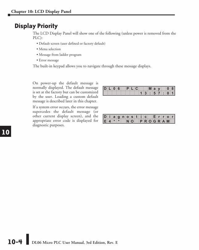
Display PriorityThe LCD Display Panel will show one of the following (unless power is removed from the PLC):
• Default screen (user defined or factory default)
• Menu selection
• Message from ladder program
• Error message
The built-in keypad allows you to navigate through these message displays.
D L 0 6 P L C M a y 0 81 3 : 5 7 : 0 1
D i a g n o s t i c E r r o rE 4 * * N O P R O G R A M
On power-up the default message is normally displayed. The default message is set at the factory but can be customized by the user. Loading a custom default message is described later in this chapter.
If a system error occurs, the error message supercedes the default message (or other current display screen), and the appropriate error code is displayed for diagnostic purposes.

DL06 Micro PLC User Manual, 3rd Edition, Rev. E 10-5
Chapter 10: LCD Display Panel
1
2
3
4
5
6
7
8
9
10
11
12
13
14
A
B
C
D
Menu NavigationBeginning at the default screen, each time you press the MENU key the display will scroll to the next menu option. The up arrow and down arrow keys also scroll through the list of menus (in the direction indicated by the arrow), but you must initially press the MENU key (at the default screen) to activate the up and down arrow keys.
There are seven built-in menus selections. Some of the menu items have sub-menus. The menus and sub-menus are described in this chapter. Each menu selection requires that you press the ENT key to view or change settings or values within the domain of that main menu selection.
Seven Menu ChoicesPressing and holding the MENU key will cause the display to scroll through the following menu options:
• M1 : PLC information
• M2 : System configuration
• M3 : Monitor
• M4 : Calendar read/write
• M5 : Password read/write
• M6 : Error history read
• M7 : LCD test and set
In this section we use illustrations of the LCD Display Panel keypad and display area to show how to navigate through the menu hierarchy. The example below shows the factory default screen as Screen 1 and the main menu entry screen as Screen 2.
The illustration of the keypad between the display screens indicates that pressing the MENU key causes a transition from Screen 1 to Screen 2. This type of representation is used throughout this section. When inside the menu hierarchy, the ESC key returns the display to the previous screen.
1
2
3
4
5
6
7
8
9
10
11
12
13
14
a
B
C
D
M E N U S C R E E N> M 1 : P L C I N F O .
> M 6 : E R R H I S T O R Y> M 7 : L C D T E S T & S E T
> M 4 : C A L E N D A R R / W> M 5 : P A S S W O R D R / W
M E N U S C R E E N> M 1 : P L C I N F O .
ESC MENU ENT
D L 0 6 P L C M a y 0 81 4 : 1 2 : 0 1
Press the MENU key to
transition from screen 1 to screen 2.
Screen 1 - factory default
Screen 2
> M 2 : S Y S T E M C F G > M 3 : M O N I T O R

DL06 Micro PLC User Manual, 3rd Edition, Rev. E10-6
Chapter 10: LCD Display Panel
1
2
3
4
5
6
7
8
9
10
11
12
13
14
A
B
C
D
1
2
3
4
5
6
7
8
9
10
11
12
13
14
a
B
C
D
Menu 1, M1:PLC INFO. From the default screen, press the MENU key one time to arrive at the PLC INFO menu option.
ESC MENU ENT
M 1 : P L C T Y P ED 0 - 0 6 D D 1
M 1 : P L C M O D ER U N
ESC MENU ENT
ESC MENU ENT
M E N U S C R E E N> M 1 : P L C I N F O .
Default screen
Step 1.1
Step 1.2
Step 1.3
ESC MENU ENT
D L 0 6 P L C M a y 0 81 4 : 1 2 : 0 1
Confirm PLC Type, Firmware Revision Level, Memory Usage, Etc.
NOTE: The menu screen examples shown in this section assume the password/lock feature is not turned on. If the password/lock feature is turned on, the user will be prompted by a message on the Display Panel to enter the password at the appropriate time. Users without password authorization will have access to a limited number of screens.
Press ENT to enter this menu selection. The first screen inside the PLC INFO selection is M1:PLC TYPE. This selection displays the model number of the PLC.
Press MENU again to sequence to PLC MODE. The PLC mode is either RUN, STOP (for Stop or Program Mode), TEST-STOP (for Test Stop Mode), or TEST-RUN (for Test Run Mode). You can put the DL06 in the Test Run Mode from the Test Stop Mode.

DL06 Micro PLC User Manual, 3rd Edition, Rev. E 10-7
Chapter 10: LCD Display Panel
1
2
3
4
5
6
7
8
9
10
11
12
13
14
A
B
C
D
1
2
3
4
5
6
7
8
9
10
11
12
13
14
a
B
C
D
ESC MENU ENT
ESC MENU ENT
ESC MENU ENT
M E N U S C R E E N> M 1 : P L C I N F O .
M 1 : L A D D E R P A S S W DN O T A C T I V A T E D
M 1 : L A D D E R M E M O R YU S E D 2 1 / 7 6 8 0
ESC MENU ENT
Default screen
Return to Step 1.1
Step 1.6
Step 1.5
M 1 : F I R M W A R E R E V .V 1 . 0 0 0
Step 1.4
D L 0 6 P L C M a y 0 81 4 : 2 2 : 1 1
Press MENU again to sequence to FIRMWARE REV.
Press MENU again to sequence to LADDER MEMORY USED. The number of words used and the total number available in the PLC are displayed.
Press MENU again to sequence to LADDER PASSWORD, ACTIVATED OR NOT ACTIVATED. This is the last screen of the PLC INFO menu and is self-explanatory.
Press ESC to exit the M1 menu and return to the main menu.
Press ESC once more to return to the default screen.
DL06 Micro PLC User Manual, 3rd Edition, Rev. E10-8
Chapter 10: LCD Display Panel
1
2
3
4
5
6
7
8
9
10
11
12
13
14
A
B
C
D
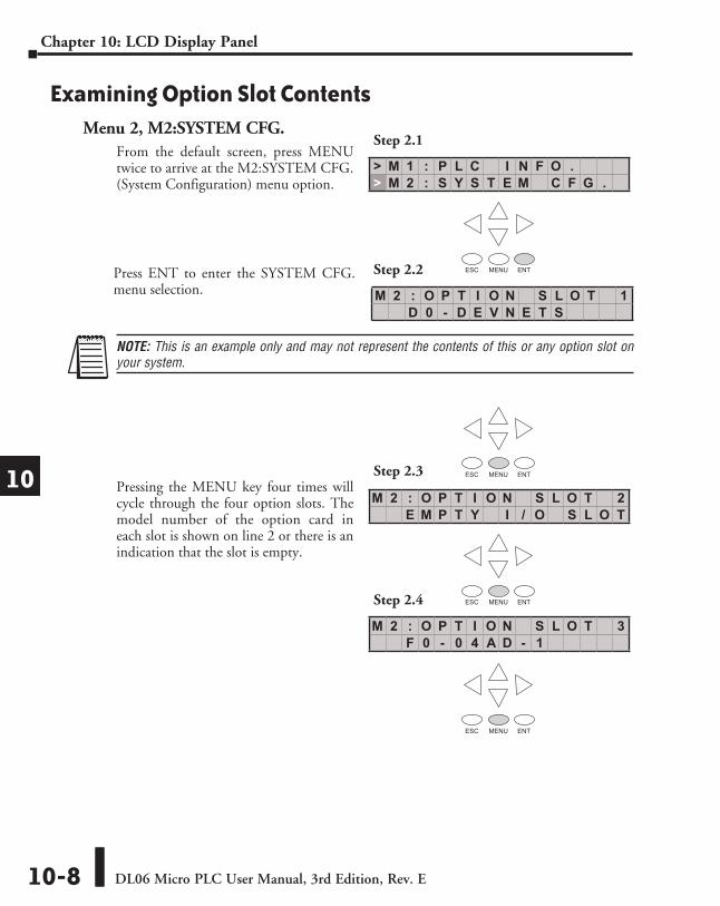
Examining Option Slot ContentsMenu 2, M2:SYSTEM CFG. 1
2
3
4
5
6
7
8
9
10
11
12
13
14
a
B
C
D
M 2 : O P T I O N S L O T 3F 0 - 0 4 A D - 1
M 2 : O P T I O N S L O T 2E M P T Y I / O S L O T
ESC MENU ENT
ESC MENU ENT
ESC MENU ENT
ESC MENU ENT
> M 1 : P L C I N F O .> M 2 : S Y S T E M C F G .
NOTE: This is an example only and may not represent the contents of this or any option slot on your system.
From the default screen, press MENU twice to arrive at the M2:SYSTEM CFG. (System Configuration) menu option.
Pressing the MENU key four times will cycle through the four option slots. The model number of the option card in each slot is shown on line 2 or there is an indication that the slot is empty.
Step 2.2
Step 2.3
Step 2.4
Step 2.1
M 2 : O P T I O N S L O T 1D 0 - D E V N E T S
Press ENT to enter the SYSTEM CFG. menu selection.
DL06 Micro PLC User Manual, 3rd Edition, Rev. E 10-9
Chapter 10: LCD Display Panel
1
2
3
4
5
6
7
8
9
10
11
12
13
14
A
B
C
D
1
2
3
4
5
6
7
8
9
10
11
12
13
14
a
B
C
D
ESC MENU ENT
ESC MENU ENT
D L 0 6 P L C M a y 0 81 4 : 5 7 : 2 1
> M 1 : P L C I N F O .> M 2 : S Y S T E M C F G .
M 2 : O P T I O N S L O T 4E M P T Y I / O S L O T
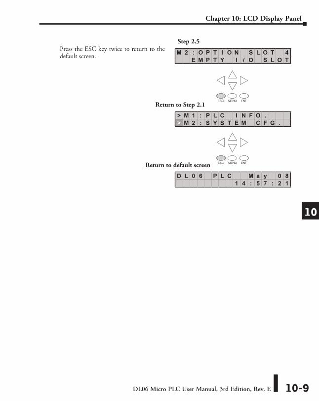
Press the ESC key twice to return to the default screen.
Step 2.5
Return to Step 2.1
Return to default screen
DL06 Micro PLC User Manual, 3rd Edition, Rev. E10-10
Chapter 10: LCD Display Panel
1
2
3
4
5
6
7
8
9
10
11
12
13
14
A
B
C
D
1
2
3
4
5
6
7
8
9
10
11
12
13
14
a
B
C
D
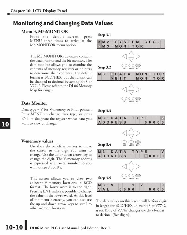
Monitoring and Changing Data ValuesMenu 3, M3:MONITOR
From the default screen, press MENU three times to arrive at the M3:MONITOR menu option.
The M3:MONITOR sub-menu contains the data monitor and the bit monitor. The data monitor allows you to examine the contents of memory registers or pointers to determine their contents. The default format is BCD/HEX, but the format can be changed to decimal by setting bit 8 of V7742. Please refer to the DL06 Memory Map for ranges.
Data MonitorData type = V for V-memory or P for pointer. Press MENU to change data type, or press ENT to designate the register whose data you want to view or change.
V-memory valuesUse the right or left arrow key to move the cursor to the digit you want to change. Use the up or down arrow key to change the digit. The V-memory address is expressed as an octal number so you will not see 8’s or 9’s.
This screen allows you to view two adjacent V-memory locations in BCD format. The lower word is to the right. Pressing ENT makes it possible to change the value in the lower word. At this level of the menu hierarchy, you can also use the up and down arrow keys to scroll to other memory locations.
The data values on this screen will be four digits in length for BCD/HEX unless bit 8 of V7742 is set. Bit 8 of V7742 changes the data format to decimal (five digits).
M 3 : D A T A T Y P E VA D D R E S S 0 0 0 0 0
ESC MENU ENT
M 3 : D A T A T Y P E VA D D R E S S 0 0 0 0 0
M 3 : > D A T A M O N I T O R> B I T M O N I T O R
> M 2 : S Y S T E M C F G .> M 3 : M O N I T O R
ESC MENU ENT
ESC MENU ENT
ESC MENU ENT
Step 3.1
Step 3.2
Step 3.3
Step 3.4
Step 3.5
M 3 : V 1 V 0V A L 0 0 0 0 0 0 0 0

DL06 Micro PLC User Manual, 3rd Edition, Rev. E 10-11
Chapter 10: LCD Display Panel
1
2
3
4
5
6
7
8
9
10
11
12
13
14
A
B
C
D
1
2
3
4
5
6
7
8
9
10
11
12
13
14
a
B
C
D
M 3 : D A T A T Y P E VA D D R E S S 0 0 0 0 0
M 3 : V 1 V 0V A L 0 0 0 0 A F 0 6
M 3 : D A T A V 0C H G = 0 0 0 0 0 0 0 0
M 3 : D A T A V 0C H G = A F 0 6 0 0 0 0
ESC MENU ENT
ESC MENU ENT
ESC MENU ENT
Use the right or left arrow key to move the cursor to the digit you want to change. Use the up or down arrow key to move to another digit. The V-memory value is expressed as a BCD number so you will see values (in the range: 0 - F) available for each digit. The data format can be changed to decimal by setting bit 8 of V7742.
ESC MENU ENT
ESC MENU ENT
Step 3.8
Returns to Step 1.1
Returns to default screen
Step 3.7
Step 3.6
D L 0 6 P L C M a y 0 81 5 : 0 2 : 1 3
Push the ESC key five (5) times to return to the default screen.
DL06 Micro PLC User Manual, 3rd Edition, Rev. E10-12
Chapter 10: LCD Display Panel
1
2
3
4
5
6
7
8
9
10
11
12
13
14
A
B
C
D
1
2
3
4
5
6
7
8
9
10
11
12
13
14
a
B
C
D
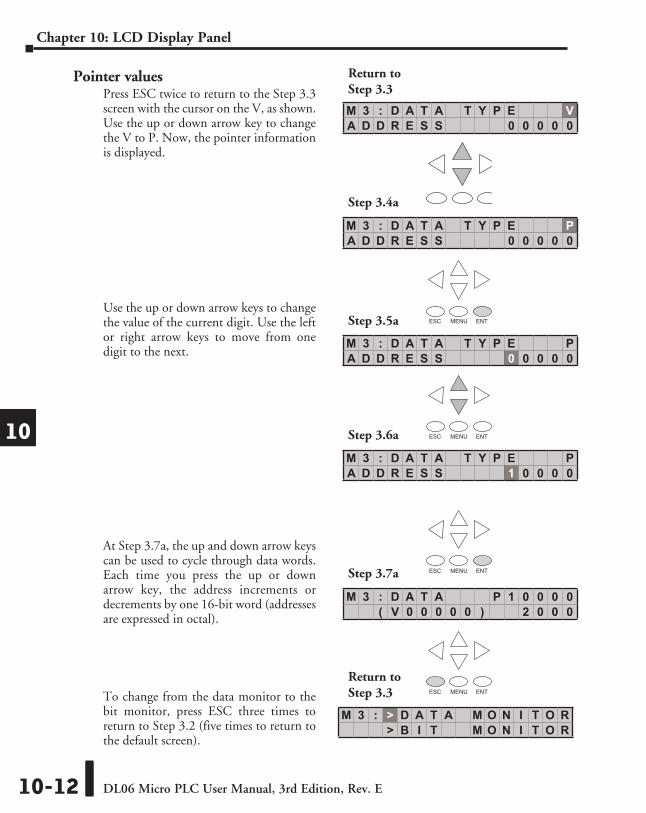
Pointer valuesPress ESC twice to return to the Step 3.3 screen with the cursor on the V, as shown. Use the up or down arrow key to change the V to P. Now, the pointer information is displayed.
Use the up or down arrow keys to change the value of the current digit. Use the left or right arrow keys to move from one digit to the next.
At Step 3.7a, the up and down arrow keys can be used to cycle through data words. Each time you press the up or down arrow key, the address increments or decrements by one 16-bit word (addresses are expressed in octal).
To change from the data monitor to the bit monitor, press ESC three times to return to Step 3.2 (five times to return to the default screen).
ESC MENU ENT
ESC MENU ENT
ESC MENU ENT
ESC MENU ENT
M 3 : D A T A P 1 0 0 0 0( V 0 0 0 0 0 ) 2 0 0 0
M 3 : D A T A T Y P E PA D D R E S S 0 0 0 0 0
M 3 : D A T A T Y P E PA D D R E S S 1 0 0 0 0
M 3 : D A T A T Y P E PA D D R E S S 0 0 0 0 0
M 3 : D A T A T Y P E VA D D R E S S 0 0 0 0 0
Return to Step 3.3
Step 3.4a
Step 3.5a
Step 3.6a
Step 3.7a
ESC MENU ENT
M 3 : > D A T A M O N I T O R> B I T M O N I T O R
Return to Step 3.3

DL06 Micro PLC User Manual, 3rd Edition, Rev. E 10-13
Chapter 10: LCD Display Panel
1
2
3
4
5
6
7
8
9
10
11
12
13
14
A
B
C
D
1
2
3
4
5
6
7
8
9
10
11
12
13
14
a
B
C
D
Bit statusFrom Step 3.3, press the up or down arrow key, then the ENT key. You will see one of eleven bit data types displayed. The data type that appears on the display is the last data type accessed. The address shown is also the last address accessed for that particular data type.
Press ENT to change the address.
Use the arrow keys to change the address as necessary.
Press ENT to view the selected bits.
Use the left and right arrow keys to select a bit whose status you want to change. Press ENT once to see the change status screen. Press ENT again to change the status from OFF to ON or ON to OFF.
Bit Monitor
ESC MENU ENT
ESC MENU ENT
Return to Step 3.3
M 3 : D A T A T Y P E PA D D R E S S 0 0 0 0 0
M 3 : B I T T Y P E VA D D R E S S 0 0 0 0 0
M 3 : B I T T Y P E CA D D R E S S 0 0 0 0 0
M 3 : B I T T Y P E VA D D R E S S 0 2 5 0 0
M 3 : B I T - 0 0 V 2 5 0 0o o o o o o o o o o o o o o o o
M 3 : B I T - 0 2 V 2 5 0 0C H G = O N S T A T : O F F
ESC MENU ENT
ESC MENU ENT
ESC MENU ENT
Return to Step 3.3
ESC MENU ENT
DL06 Micro PLC User Manual, 3rd Edition, Rev. E10-14
Chapter 10: LCD Display Panel
1
2
3
4
5
6
7
8
9
10
11
12
13
14
A
B
C
D
1
2
3
4
5
6
7
8
9
10
11
12
13
14
a
B
C
D
> M 3 : D A T A T Y P E> M 4 : C A L E N D A R R / W
M 4 : D A T E 0 5 - 0 8 - 0 2T I M E 0 1 : 2 1 : 2 8
M 4 : > C H A N G E D A T E> C H A N G E T I M E
M 4 : D A T E M M - D D - Y YC H G = 0 5 - 0 8 - 0 2
M 4 : D A T E M M - D D - Y YS E T ? 0 5 - 0 8 - 0 2
Step 4.1
Step 4.2
Step 4.3
Step 4.4
Step 4.5
ESC MENU ENT
ESC MENU ENT
ESC MENU ENT
ESC MENU ENT
ESC MENU ENT
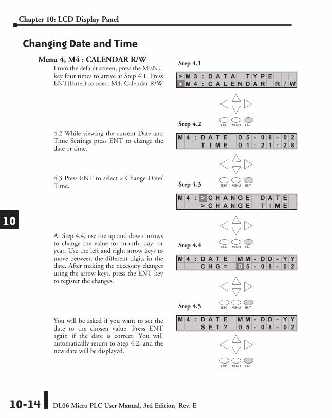
Changing Date and TimeMenu 4, M4 : CALENDAR R/W
From the default screen, press the MENU key four times to arrive at Step 4.1. Press ENT(Enter) to select M4: Calendar R/W
4.2 While viewing the current Date and Time Settings press ENT to change the date or time.
4.3 Press ENT to select > Change Date/Time.
At Step 4.4, use the up and down arrows to change the value for month, day, or year. Use the left and right arrow keys to move between the different digits in the date. After making the necessary changes using the arrow keys, press the ENT key to register the changes.
You will be asked if you want to set the date to the chosen value. Press ENT again if the date is correct. You will automatically return to Step 4.2, and the new date will be displayed.
DL06 Micro PLC User Manual, 3rd Edition, Rev. E 10-15
Chapter 10: LCD Display Panel
1
2
3
4
5
6
7
8
9
10
11
12
13
14
A
B
C
D
1
2
3
4
5
6
7
8
9
10
11
12
13
14
a
B
C
D
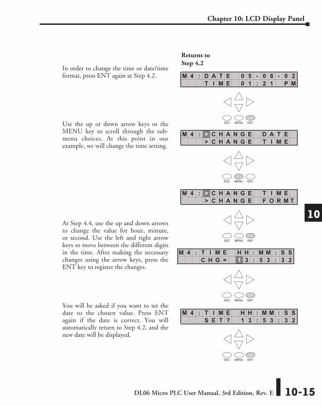
In order to change the time or date/time format, press ENT again at Step 4.2.
Use the up or down arrow keys or the MENU key to scroll through the sub-menu choices. At this point in our example, we will change the time setting.
At Step 4.4, use the up and down arrows to change the value for hour, minute, or second. Use the left and right arrow keys to move between the different digits in the time. After making the necessary changes using the arrow keys, press the ENT key to register the changes.
You will be asked if you want to set the date to the chosen value. Press ENT again if the date is correct. You will automatically return to Step 4.2, and the new date will be displayed.
M 4 : D A T E 0 5 - 0 8 - 0 2T I M E 0 1 : 2 1 P M
Returns to Step 4.2
ESC MENU ENT
ESC MENU ENT
ESC MENU ENT
ESC MENU ENT
M 4 : > C H A N G E D A T E> C H A N G E T I M E
M 4 : > C H A N G E T I M E> C H A N G E F O R M T
ESC MENU ENT
M 4 : T I M E H H : M M : S SC H G = 1 3 : 5 3 : 3 2
M 4 : T I M E H H : M M : S SS E T ? 1 3 : 5 3 : 3 2
DL06 Micro PLC User Manual, 3rd Edition, Rev. E10-16
Chapter 10: LCD Display Panel
1
2
3
4
5
6
7
8
9
10
11
12
13
14
A
B
C
D
1
2
3
4
5
6
7
8
9
10
11
12
13
14
a
B
C
D
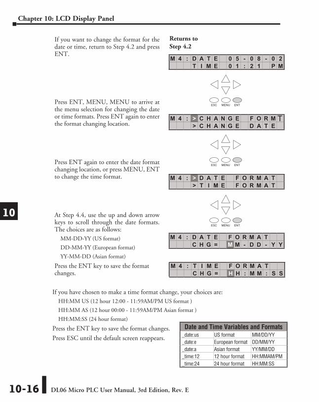
If you want to change the format for the date or time, return to Step 4.2 and press ENT.
Press ENT, MENU, MENU to arrive at the menu selection for changing the date or time formats. Press ENT again to enter the format changing location.
Press ENT again to enter the date format changing location, or press MENU, ENT to change the time format.
At Step 4.4, use the up and down arrow keys to scroll through the date formats. The choices are as follows:
MM-DD-YY (US format)
DD-MM-YY (European format)
YY-MM-DD (Asian format)
Press the ENT key to save the format changes.
If you have chosen to make a time format change, your choices are:HH:MM US (12 hour 12:00 - 11:59AM/PM US format )
HH:MM AS (12 hour 00:00 - 11:59AM/PM Asian format )
HH:MM:SS (24 hour format)
Press the ENT key to save the format changes.
Press ESC until the default screen reappears.
M 4 : D A T E 0 5 - 0 8 - 0 2T I M E 0 1 : 2 1 P M
Returns to Step 4.2
ESC MENU ENT
ESC MENU ENT
ESC MENU ENT
M 4 : > D A T E F O R M A T> T I M E F O R M A T
M 4 : D A T E F O R M A TC H G = M M - D D - Y Y
M 4 : T I M E F O R M A TC H G = H H : M M : S S
M 4 : > C H A N G E F O R M T> C H A N G E D A T E
Date and Time Variables and Formats_date:us US format MM/DD/YY_date:e European format DD/MM/YY_date:a Asian format YY/MM/DD_time:12 12 hour format HH:MMAM/PM_time:24 24 hour format HH:MM:SS
DL06 Micro PLC User Manual, 3rd Edition, Rev. E 10-17
Chapter 10: LCD Display Panel
1
2
3
4
5
6
7
8
9
10
11
12
13
14
A
B
C
D
1
2
3
4
5
6
7
8
9
10
11
12
13
14
a
B
C
D
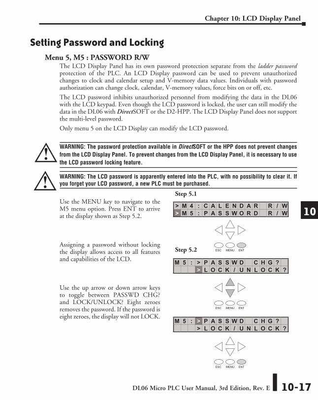
Setting Password and LockingMenu 5, M5 : PASSWORD R/W
The LCD Display Panel has its own password protection separate from the ladder password protection of the PLC. An LCD Display password can be used to prevent unauthorized changes to clock and calendar setup and V-memory data values. Individuals with password authorization can change clock, calendar, V-memory values, force bits on or off, etc.
The LCD password inhibits unauthorized personnel from modifying the data in the DL06 with the LCD keypad. Even though the LCD password is locked, the user can still modify the data in the DL06 with DirectSOFT or the D2-HPP. The LCD Display Panel does not support the multi-level password.
Only menu 5 on the LCD Display can modify the LCD password.
WARNING: The password protection available in DirectSOFT or the HPP does not prevent changes from the LCD Display Panel. To prevent changes from the LCD Display Panel, it is necessary to use the LCD password locking feature.
WARNING: The LCD password is apparently entered into the PLC, with no possibility to clear it. If you forget your LCD password, a new PLC must be purchased.
Use the MENU key to navigate to the M5 menu option. Press ENT to arrive at the display shown as Step 5.2.
Assigning a password without locking the display allows access to all features and capabilities of the LCD.
Use the up arrow or down arrow keys to toggle between PASSWD CHG? and LOCK/UNLOCK? Eight zeroes removes the password. If the password is eight zeroes, the display will not LOCK.
Step 5.1
Step 5.2
> M 4 : C A L E N D A R R / W> M 5 : P A S S W O R D R / W
ESC MENU ENT
M 5 : > P A S S W D C H G ?> L O C K / U N L O C K ?
ESC MENU ENT
M 5 : > P A S S W D C H G ?> L O C K / U N L O C K ?
ESC MENU ENT

DL06 Micro PLC User Manual, 3rd Edition, Rev. E10-18
Chapter 10: LCD Display Panel
1
2
3
4
5
6
7
8
9
10
11
12
13
14
A
B
C
D
1
2
3
4
5
6
7
8
9
10
11
12
13
14
a
B
C
D
It is not possible to lock the display without assigning a password. It is possible to assign a password without locking the display, but doing so will not protect sensitive data.
Press the ENT key at Step 5.2, and the display is now locked. If you do not wish to lock the display at this point, press ESC.
Use the up arrow or down arrow keys to scroll through number choices, and use the right arrow and left arrow keys to move from one digit position to another.
NOTE: It is important to record the password where it will not be forgotten and to issue the password only to qualified personnel. Full access to the LCD Display Panel gives access to change data values within the PLC.
M 5 : S T A T : U N L O C K E DE N T T O L O C K
M 5 : P S W D * * * * * * * *C H G = 0 0 0 0 0 0 0 0
M 5 : P S W D * * * * * * * *C H G = 2 1 7 0 8 3 0 3
M 5 : P S W D * * * * * * * *S E T ? 2 1 7 0 8 3 0 3
ESC MENU ENT
ESC MENU ENT
ESC MENU ENT
ESC MENU ENT
M 5 : > P A S S W D C H G ?> L O C K / U N L O C K ?
Return to Step 5.2
DL06 Micro PLC User Manual, 3rd Edition, Rev. E 10-19
Chapter 10: LCD Display Panel
1
2
3
4
5
6
7
8
9
10
11
12
13
14
A
B
C
D
1
2
3
4
5
6
7
8
9
10
11
12
13
14
a
B
C
D
M 5 : > P A S S W D C H G ?> L O C K / U N L O C K ?
Return to Step 5.2
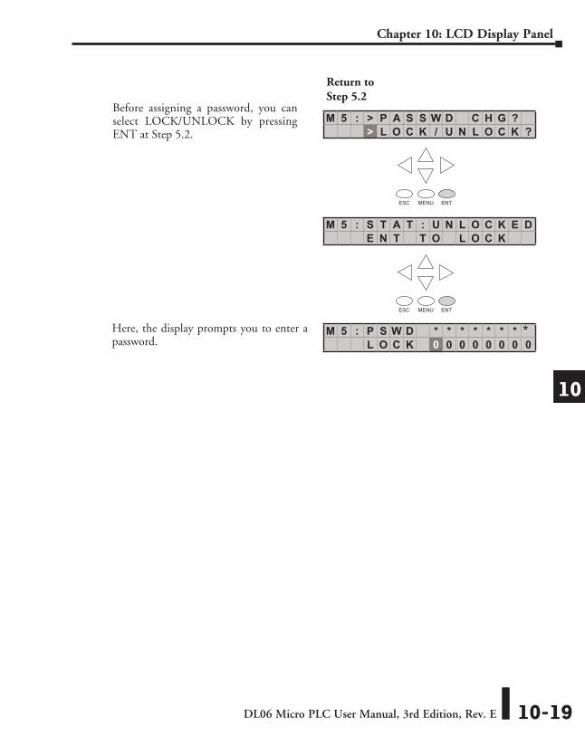
Before assigning a password, you can select LOCK/UNLOCK by pressing ENT at Step 5.2.
ESC MENU ENT
ESC MENU ENT
M 5 : S T A T : U N L O C K E DE N T T O L O C K
M 5 : P S W D * * * * * * * *L O C K 0 0 0 0 0 0 0 0
Here, the display prompts you to enter a password.
DL06 Micro PLC User Manual, 3rd Edition, Rev. E10-20
Chapter 10: LCD Display Panel
1
2
3
4
5
6
7
8
9
10
11
12
13
14
A
B
C
D
1
2
3
4
5
6
7
8
9
10
11
12
13
14
a
B
C
D
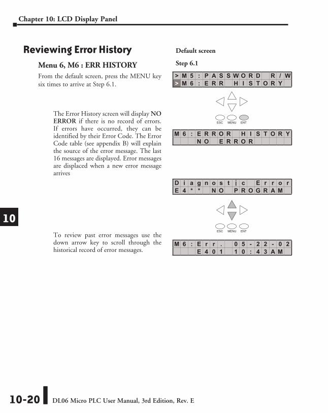
Reviewing Error HistoryMenu 6, M6 : ERR HISTORYFrom the default screen, press the MENU key six times to arrive at Step 6.1.
The Error History screen will display NO ERROR if there is no record of errors. If errors have occurred, they can be identified by their Error Code. The Error Code table (see appendix B) will explain the source of the error message. The last 16 messages are displayed. Error messages are displaced when a new error message arrives
To review past error messages use the down arrow key to scroll through the historical record of error messages.
> M 5 : P A S S W O R D R / W> M 6 : E R R H I S T O R Y
M 6 : E R R O R H I S T O R YN O E R R O R
D i a g n o s t i c E r r o rE 4 * * N O P R O G R A M
M 6 : E r r . 0 5 - 2 2 - 0 2E 4 0 1 1 0 : 4 3 A M
Default screen
Step 6.1
ESC MENU ENT
ESC MENU ENT
DL06 Micro PLC User Manual, 3rd Edition, Rev. E 10-21
Chapter 10: LCD Display Panel
1
2
3
4
5
6
7
8
9
10
11
12
13
14
A
B
C
D
1
2
3
4
5
6
7
8
9
10
11
12
13
14
a
B
C
D
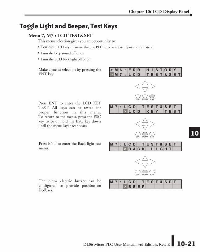
Toggle Light and Beeper, Test KeysMenu 7, M7 : LCD TEST&SET
This menu selection gives you an opportunity to:
• Test each LCD key to assure that the PLC is receiving its input appropriately
• Turn the beep sound off or on
• Turn the LCD back light off or on
> M 6 : E R R H I S T O R Y> M 7 : L C D T E S T & S E T
M 7 : L C D T E S T & S E T> L C D K E Y T E S T
M 7 : L C D T E S T & S E T> B A C K L I G H T
M 7 : L C D T E S T & S E T> B E E P
ESC MENU ENT
ESC MENU ENT
ESC MENU ENT
The piezo electric buzzer can be configured to provide pushbutton feedback.
Make a menu selection by pressing the ENT key.
Press ENT to enter the LCD KEY TEST. All keys can be tested for proper function in this menu. To return to the menu, press the ESC key twice or hold the ESC key down until the menu layer reappears.
Press ENT to enter the Back light test menu.

DL06 Micro PLC User Manual, 3rd Edition, Rev. E10-22
Chapter 10: LCD Display Panel
1
2
3
4
5
6
7
8
9
10
11
12
13
14
A
B
C
D
1
2
3
4
5
6
7
8
9
10
11
12
13
14
a
B
C
D
PLC Memory Information for the LCD Display PanelThe valid memory ranges for storing text messages in the DL06 are:
Data Format Suffixes for Embedded V-memory DataSeveral data formats are available for displaying V-memory data on the LCD. The choices are shown in the table below. A colon is used to separate the embedded V-memory location from the data format suffix and modifier.
Data Format Modifier Example Character Position/Content of the Output
none (16 bit binary
in HEX format)
V2000 = 0012 1 2 3 4V2000 s s 1 8
S [:S] V2000:S 1 8 C0 [:C0] V2000:C0 0 0 1 80 [:0] V2000:0 s s 1 8
:B (4 digit BCD)
V2000 = 0012 1 2 3 4[:B] V2000:B 0 0 1 2
S [:BS] V2000:BS 1 2 C0 [:BC0] V2000:BC0 0 0 1 20 [:B0] V2000:B0 s s 1 2
:D (32 bit binary)
V2000 = 0000V2001 = 0001 1 2 3 4 5 6 7 8 9 10 11
[:D] V2000:D s s s s s s 6 5 5 3 6S [:DS] V2000:DS 6 5 5 3 6C0 [:DC0] V2000:DC0 0 0 0 0 0 0 6 5 5 3 60 [:D0] V2000:D0 s s s s s s 6 5 5 3 6
:DB (8 digit BCD)
V2000 = 0000V2001 = 0001 1 2 3 4 5 6 7 8
[:DB] V2000:DB 0 0 0 1 0 0 0 0S [:DBS] V2000:DBS 1 0 0 0 0C0 [:DBC0] V2000:DBC0 0 0 0 1 0 0 0 00 [:DB0] V2000:DB0 s s s 1 0 0 0 0
:R (Floating point
number)
Value = 222.11111V2000 = 1C72V2001 = 435E 1 2 3 4 5 6 7 8 9 10 11 12 13
[:R] V2000:R s s s f 2 2 2 . 1 1 1 1 1S [:RS] V2000:RS f 2 2 2 . 1 1 1 1 1C0 [:RC0] V2000:RC0 f 0 0 0 2 2 2 . 1 1 1 1 10 [:R0] V2000:R0 s s s f 2 2 2 . 1 1 1 1 1
:E (Floating point number with
exponent)
Value = 222.1V2000 = 199AV2001 = 435E 1 2 3 4 5 6 7 8 9 10 11 12 13
[:E] V2000:E s f 2 . 2 2 1 0 0 E + 0 2S [:ES] V2000:ES f 2 . 2 2 1 0 0 E + 0 2C0 [:EC0] V2000:EC0 f 2 . 2 2 1 0 0 E + 0 20 [:E0] V2000:E0 f 2 . 2 2 1 0 0 E + 0 2
s = space f = plus/minus flag (plus = no symbol, minus = - )
V400 - V677 V1200 - V7577 V10000 - V17777

DL06 Micro PLC User Manual, 3rd Edition, Rev. E 10-23
Chapter 10: LCD Display Panel
1
2
3
4
5
6
7
8
9
10
11
12
13
14
A
B
C
D
1
2
3
4
5
6
7
8
9
10
11
12
13
14
a
B
C
D
Reserved memory registers for the LCD Display PanelTwo V-memory registers are reserved for making changes to LCD functions via ladder logic. V7742 allows for bit flags to be set in the ladder program. The bit flags control such things as data formats, the back light, and the beeper. All V7742 bit flags are defined in the table on the next page.
The other reserved register is V7743. This register is used to write a customized default screen message to the LCD. A sample program for this purpose is illustrated later in this chapter.
C0
SET
C1
RST
B7742.12
B7742.12
V-memory address Contents
V7742
Various LCD flags• Calendar date and time format • Default operation menu • Data format of data monitor • LCD password status flag • Key press acknowledgement buzzer on/off setting • Back light on/off setting
V7743 Default message location (writing 0 to this address returns the default message to the factory setting)
The following program segment uses the SET and RST coils to turn on and off bit 12 of V7742. When C0 is on, bit 12 is turned on. Bit 12 turns on the beeper in the LCD Display Panel. The C1 contact resets bit 12 to the off state.
The S, C0 and 0 modifiers alter the presentation of leading zeros and spaces. S removes leading spaces and left justifies the result. C0 replaces leading spaces with leading zeros. 0 is a modification of C0. 0 eliminates any leading zeros in the C0 format version and converts them to spaces.
DL06 Micro PLC User Manual, 3rd Edition, Rev. E10-24
Chapter 10: LCD Display Panel
1
2
3
4
5
6
7
8
9
10
11
12
13
14
A
B
C
D
1
2
3
4
5
6
7
8
9
10
11
12
13
14
a
B
C
D
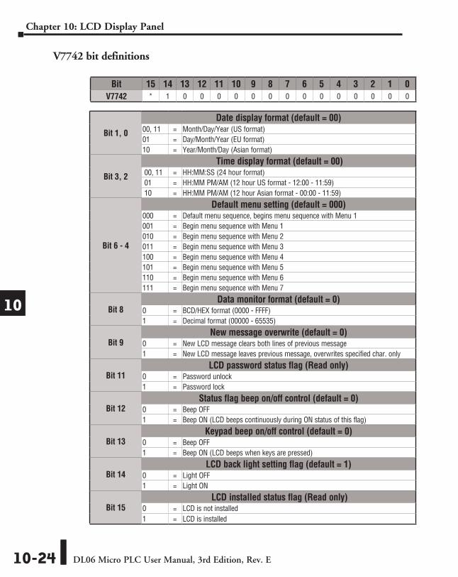
Bit 15 14 13 12 11 10 9 8 7 6 5 4 3 2 1 0V7742 * 1 0 0 0 0 0 0 0 0 0 0 0 0 0 0
Bit 1, 0
Date display format (default = 00)00, 11 = Month/Day/Year (US format)01 = Day/Month/Year (EU format)10 = Year/Month/Day (Asian format)
Bit 3, 2
Time display format (default = 00)00, 11 = HH:MM:SS (24 hour format)01 = HH:MM PM/AM (12 hour US format - 12:00 - 11:59)10 = HH:MM PM/AM (12 hour Asian format - 00:00 - 11:59)
Bit 6 - 4
Default menu setting (default = 000)000 = Default menu sequence, begins menu sequence with Menu 1001 = Begin menu sequence with Menu 1010 = Begin menu sequence with Menu 2011 = Begin menu sequence with Menu 3100 = Begin menu sequence with Menu 4101 = Begin menu sequence with Menu 5110 = Begin menu sequence with Menu 6111 = Begin menu sequence with Menu 7
Bit 8Data monitor format (default = 0)
0 = BCD/HEX format (0000 - FFFF)1 = Decimal format (00000 - 65535)
Bit 9New message overwrite (default = 0)
0 = New LCD message clears both lines of previous message1 = New LCD message leaves previous message, overwrites specified char. only
Bit 11LCD password status flag (Read only)
0 = Password unlock1 = Password lock
Bit 12Status flag beep on/off control (default = 0)
0 = Beep OFF1 = Beep ON (LCD beeps continuously during ON status of this flag)
Bit 13Keypad beep on/off control (default = 0)
0 = Beep OFF1 = Beep ON (LCD beeps when keys are pressed)
Bit 14LCD back light setting flag (default = 1)
0 = Light OFF1 = Light ON
Bit 15LCD installed status flag (Read only)
0 = LCD is not installed1 = LCD is installed
V7742 bit definitions

DL06 Micro PLC User Manual, 3rd Edition, Rev. E 10-25
Chapter 10: LCD Display Panel
1
2
3
4
5
6
7
8
9
10
11
12
13
14
A
B
C
D
1
2
3
4
5
6
7
8
9
10
11
12
13
14
a
B
C
D
Changing the Default ScreenAt power-up the default screen is displayed. The default screen message is set at the factory but can be customized by the user. One method of customizing the default message uses the VPRINT instruction. The VPRINT instruction is described in Chapter 5.
Example program for setting the default screen messageThe following program can be used to set up the default screen message. This program uses the VPRINT instruction to load ASCII text to a designated V-memory location and to embed a pointer to the current date.
The LDA and OUT instructions are used to point to the V-memory location (+1) where the text is located. The memory location V7743 is reserved for the pointer to the default message.
NOTE: The VPRINT instruction adds a one word (2 bytes) non-printing header to the text. For this reason, the LDA instruction points to the V-memory location V10001 rather than V10000.
After running this program, press MENU, then ESC or cycle power. The new default message should look as indicated. See Menu 4 instructions for changing date and time information.
NOTE: It is possible to return to the factory default screen by writing 0 to V7743 and cycling power.
SP0VPRINT
Byte Swap: None
"Print to" Address: V10000
"AutomationDirect"
END
LDA
O10001
OUT
V7743
SP0
A u t o m a t i o n D i r e c t
V10000 00h 16h
V10001 u A
V10002 o t
V10003 a m
V10004 i t
V10005 n o
V10006 i D
V10007 e r
V10010 t c
V10011V10012V10013V10014V10015V10016V10017V10020
D L 0 6 P L C M a y 0 81 4 : 2 0 : 4 9
Factory default message

DL06 Micro PLC User Manual, 3rd Edition, Rev. E10-26
Chapter 10: LCD Display Panel
1
2
3
4
5
6
7
8
9
10
11
12
13
14
A
B
C
D
1
2
3
4
5
6
7
8
9
10
11
12
13
14
a
B
C
D
DL06 LCD Display Panel Instruction (LCD)
From the DirectSOFT project folder, use the Instruction Browser to locate the LCD instruction. When you select the LCD instruction and click OK, the LCD dialog will appear.
The LCD Display Panel instruction is inserted into the ladder program via the set-up dialog box shown to the right. The dialog is used to specify a message to be displayed on line 1 or line 2 LCD Display Panel.
Source of messageThe text of the message can originate from one of two places. It can be input directly from the instruction as a literal text string (see figure A), or it can originate as ASCII text stored in a V-memory location (figure B). In the latter case, it is necessary to specify its beginning V-memory location and length within the dialog box.
Display text strings can include embedded data. Any V-memory value or date and time settings can be embedded in the displayed text.
NOTE: The LCD Display Panel instruction is supported by DirectSOFT, Ver. 5 or later. It is not supported by the D2-HPP handheld programmer.
figure A
figure B
LCD
Line Number: Kn
A aaa
"AAAAAAAAAAAAAAAA"
LCD
Line Number: Kn
Starting V Memory Address:
Number of Characters:
"Effluent Overflo"
"Sludge Pit Alarm"
LCD
Line Number: K1
LCD
Line Number: K2
S l u d g e P i t A l a r mE f f l u e n t O v e r f l o
DL06 Micro PLC User Manual, 3rd Edition, Rev. E 10-27
Chapter 10: LCD Display Panel
1
2
3
4
5
6
7
8
9
10
11
12
13
14
A
B
C
D
1
2
3
4
5
6
7
8
9
10
11
12
13
14
a
B
C
D
2 3 4 5 6 7
10
23456789ABCDEF
ASCIICharacter Codes
First Digit
Sec
ond
Dig
it
(BCD/HEX)
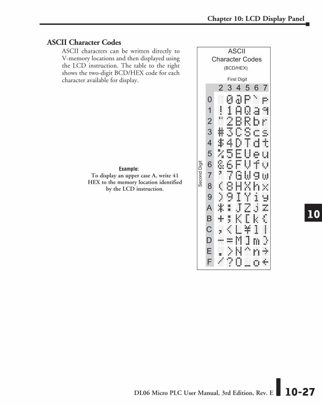
ASCII Character CodesASCII characters can be written directly to V-memory locations and then displayed using the LCD instruction. The table to the right shows the two-digit BCD/HEX code for each character available for display.
Example:To display an upper case A, write 41
HEX to the memory location identified by the LCD instruction.

DL06 Micro PLC User Manual, 3rd Edition, Rev. E10-28
Chapter 10: LCD Display Panel
1
2
3
4
5
6
7
8
9
10
11
12
13
14
A
B
C
D
1
2
3
4
5
6
7
8
9
10
11
12
13
14
a
B
C
D
Example program: alarm with embedded date/time stampThe following program will display the message “Alarm ” and the time on line K1 of the display screen with the date on line K2.
The one-shot, or positive differential (PDd), is used so that the message displays but does not block other messages or menu options. Pressing MENU or ESC will cause the alarm message text to disappear.
C0
_date:us " " _time:12
END
C1
PD
"Alarm 1 "
LCD
Line Number: K1
LCD
Line Number: K2
C1
A l a r m 10 5 / 0 8 / 0 4 5 : 2 3 P M
DL06 Micro PLC User Manual, 3rd Edition, Rev. E 10-29
Chapter 10: LCD Display Panel
1
2
3
4
5
6
7
8
9
10
11
12
13
14
A
B
C
D
1
2
3
4
5
6
7
8
9
10
11
12
13
14
a
B
C
D
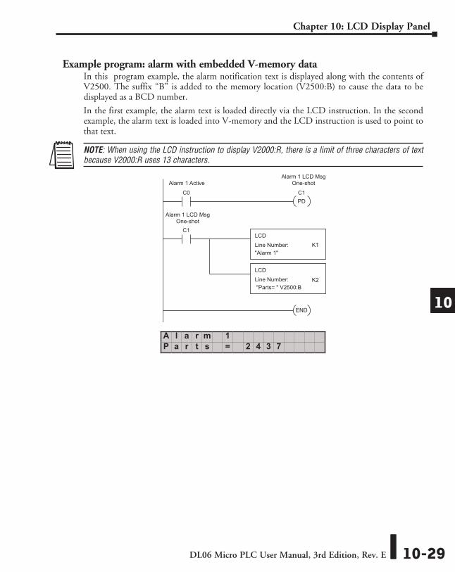
Example program: alarm with embedded V-memory dataIn this program example, the alarm notification text is displayed along with the contents of V2500. The suffix “B” is added to the memory location (V2500:B) to cause the data to be displayed as a BCD number.
In the first example, the alarm text is loaded directly via the LCD instruction. In the second example, the alarm text is loaded into V-memory and the LCD instruction is used to point to that text.
NOTE: When using the LCD instruction to display V2000:R, there is a limit of three characters of text because V2000:R uses 13 characters.
C0
"Parts= " V2500:B
END
C1
PD
"Alarm 1"
LCD
Line Number: K1
LCD
Line Number: K2
C1
Alarm 1 LCD MsgOne-shotAlarm 1 Active
Alarm 1 LCD MsgOne-shot
A l a r m 1P a r t s = 2 4 3 7
DL06 Micro PLC User Manual, 3rd Edition, Rev. E10-30
Chapter 10: LCD Display Panel
1
2
3
4
5
6
7
8
9
10
11
12
13
14
A
B
C
D
1
2
3
4
5
6
7
8
9
10
11
12
13
14
a
B
C
D
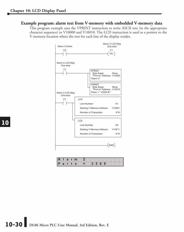
Example program: alarm text from V-memory with embedded V-memory dataThis program example uses the VPRINT instruction to write ASCII text (in the appropriate character sequence) to V10000 and V10010. The LCD instruction is used as a pointer to the V-memory location where the text for each line of the display resides.
C0
END
PD
C1
C1
V10001
LCD
Line Number: K1
Starting V Memory Address:
Number of Characters:
C1 VPRINTByte Swap: None"Print to" Address: V10000
"Alarm 2"
VPRINTByte Swap: None"Print to" Address: V10010
"Parts = " V2500:B "
V10011
LCD
Line Number: K2
Starting V Memory Address:
Number of Characters:
K16
K16
Alarm 2 LCD MsgOne-shot
Alarm 2 LCD MsgOne-shot
Alarm 2 LCD MsgOne-shot
Alarm 2 Active
A l a r m 2P a r t s = 3 5 8 9