Route to Professional Engineers BPK 4032 Engineers and Society.

CBC-4032 REMOTE PEOPLE COUNTER MODULES 8200-0745-01, REV. F INSTALLATION GUIDE 1 of 16
CBC-4032 Remote People Counter Modules Installation Guide
Contents About This Guide ........................................................... 1 Product Overview .......................................................... 1 Installation Requirements .............................................. 3 Installation ..................................................................... 3
Mounting the Back Cover ......................................... 4 Routing the Tx and Rx Cables ................................. 5 Attaching the Tx Module Top Cover ......................... 5 Connecting to a Display Device ............................... 6 Connecting to an UltraLink ....................................... 7 Connecting to a Local Device Manager (LDM) ......... 8 Connecting to an LDM via an AMS-9050
Controller ............................................................ 9 Connecting to a Digital Remote Alarm (DRA) via
AMS-9050 Controller .......................................... 9 Setup and Verification ............................................ 11 Available LDM Addresses ...................................... 12 Mounting the Rx Module ........................................ 13 Adjusting the IR Beams .......................................... 13 Resetting the Count to Zero ................................... 13 Completing the Installation ..................................... 14
© 2013 Sensormatic Electronics, LLC
Troubleshooting ...................................................... 14 Specifications ............................................................... 15 Declarations ................................................................. 15 Appendix A: Module Accessories ................................. 16 Appendix B: Direct RS-232 Connections ..................... 16
About This Guide WARNING: Do not install this device where highly combustible or explosive products are stored or used.
WARNING: Do not install this device above the ceiling when the airflow is part of the HVAC system.
Product Overview The CBC-4032 Remote People Counter Modules count people going into and out of a store or facility. • Remote People Counter Modules consist of a
transmit (Tx) module and receive (Rx) module mounted opposite each other.
• Each pair of modules can cover a zone up to 4.3m (14ft) wide.
• The Tx module contains two infrared (IR) emitters and requires a 12Vdc power supply.
• The Rx module contains two IR receivers and a circuit board. When the beams are broken sequentially: – In one direction, the circuit board records a
count of “1 in” and sends the data to a remote display device.
– In the opposite direction, the circuit board records a count of “1 out” and sends the data to a remote display device.
Tx and Rx modules: • Connect to the following remote display
devices: UltraLink, Local Device Manager, and AMS-9050 controller with AMS-1060 Digital Remote Alarm.
• Mount on a wall or metal doorframe 135±5cm (53±2in) from the floor to the horizontal center of the module.
• Can mount beyond the zone up to 18.3m (60ft) apart so they can attach to the most accessible mounting surface.
135±5cm (53±2in)
Tx Module
Rx Module
18.3m (60ft) Cables
4.3m (14ft) max. doorway width
To attach to the most accessible mounting surface, yet cover the maximum doorway width, the modules can be separated up to 18.3m (60ft) apart.
135±5cm (53±2in)

CBC-4032 REMOTE PEOPLE COUNTER MODULES 8200-0745-01, REV. F INSTALLATION GUIDE 2 of 16
Cable exit options in module
Cable Exit Options Mounting Hardware
Wood, Drywall
Cable exits side of module. –or– Cable exits top, bottom, or rear of module (remove knockouts in module). Also remove cable from cable clamp inside module. Note: If cable exits rear of module, drill through the center detent in the back cover.
Screws and Anchors
Glass, Plexiglas
Cable exits top, bottom, or side of module (remove knockouts in module). If cable exits the top or bottom, also remove cable from cable clamp inside module.
Adhesive Tape
Metal Doorframe
Cable exits side of module (remove knockout in module).
Mounting Bracket
Out side of module and into Wiremold or doorframe
If going into Wiremold, drill hole as close to rear of module as possible. If going into the doorframe, remove the side knockout.
Out rear of module and into wall
Drill out center indentation.
For this option, release the cable from the clamp.
Out top of module and into Wiremold
Drill hole below knockout so cable aligns with Wiremold. Use drain hole in module to position drill bit.
For this option, release the cable from the clamp.
Out bottom of module and into Wiremold
Drill hole below knockout so cable aligns with Wiremold. Use drain hole in module to position drill bit.
For this option, release the cable from the clamp.

CBC-4032 REMOTE PEOPLE COUNTER MODULES 8200-0745-01, REV. F INSTALLATION GUIDE 3 of 16
Installation Requirements Installer/Contractor • Shall have electrical work comply with the latest
national electrical code, national fire code, and all applicable local codes and ordinances.
• Shall coordinate work with other trades to avoid interference.
• Shall verify existing site conditions and coordinate with the owner’s representative and appropriate utilities as required.
• Shall obtain copies of all related plans, specifications, shop drawings and addenda to schedule and coordinate related work.
• Shall thoroughly review the project to ensure that all work meets or exceeds the above requirements. Any alleged discrepancies shall be brought to the attention of Sensormatic Electronics.
Mounting Requirements WARNING: Do not install this device where highly combustible or explosive products are stored or used.
CAUTION: The Rx module is sensitive to emissions from red neon signs. If neon signs are near the doorway, the Rx module should mounted to face away from the sign.
Installation It is preferable to mount the Tx and Rx modules on the edge of the wall or metal doorframe closest to the doorway (A). Although the modules can be separated up to 18.3m (60ft) apart on a wall closest to the doorway (B) if necessary, the door opening must be no more than 4.3m (14ft) wide. Note: Any break in the IR beam between the Tx and Rx modules is interpreted as a “traffic count.” To prevent erroneous counts, ensure only the intended doorway is between the modules.
Parts Required Part Qty. Part Number Module, Tx, 2-Wire 1 0101-0085-02 Module, Rx, 8-Wire 1 0101-0204-02 Install Kit 0352-0168-02 Part Qty. Part Number Sensor Cover (Appliqué) 3 2412-2085-01 Bracket, Mounting (L-Bracket) 2 0505-0859-01 Screw, Mach, M3x6, PHP 4 5801-1041-120 Screw, PWHP, M3x4 4 5899-0066-10 Screw, Typ, AB, PHP, #6x3/4” 4 2816-7634-32 Screw, Self Drill, M4, 8x25, PHP 4 5899-0031-01 Anchor, Self Drill, #6, No Screw 4 2880-0084-02 Tubing, Insulation, Clear, .042 ID,
PVC 1 3121-0033-08
Tubing, Heat Shrink, ¼ ID, 2in 1 3121-0034-01 Tape, Double-Sided, White 12in 3200-0216-02 Cable Tie, Nylon, 3.25” Long 2 6009-0002 Cable Mount, Adhesive, 3/4x3/4 2 6009-0004 Pad, Alcohol 2 1600-0033 Jack, Modular, TF Connection 1 0304-3006-01
Store A A B B
4.3m (14ft) max.
18.3m (60ft) max.

CBC-4032 REMOTE PEOPLE COUNTER MODULES 8200-0745-01, REV. F INSTALLATION GUIDE 4 of 16
Mounting the Back Cover The back cover can mount to a wall or metal doorframe.
To a Wall 1. Prepare the Tx and Rx back covers for
attachment.
If the cable is to enter the wall: Using a 4.75mm (3/16in) bit, drill through the three indentations (A). Using a 9.5mm (3/8in) bit, enlarge the center hole for cable access.
If the cable is to exit from the top, bottom, or side of the module: Using a 4.75mm (3/16in) bit, drill through the outside indentations (B). Then, using a 9.5mm (3/8in) bit, drill the appropriate hole at location (C).
2. Attach the back cover of each module to the wall using screws and anchors or adhesive tape.
Using screws and anchors: Ensuring the Tx and Rx modules are oriented correctly, place each back cover against the wall with its horizontal center 135±5cm (53±2in) above the floor, then mark the locations for cable access (A) and for two mounting screws (B). Drill a 13–19mm (1/2–3/4in) hole in the wall at the center mark for cable access, and two 4.75mm (3/16in) holes for mounting screws and/or anchors. Attach the back cover to the wall using the supplied screws and/or anchors (C).
Using adhesive tape: For each back cover:
CAUTION: Adhesive tape is not acceptable for outdoor use or for sheetrock.
Cut the supplied double-sided white adhesive tape into two 10cm (4in) strips. On the rear of the cover and starting at the flat edge, apply one strip centered along the length of the cover.
Affix the back cover to the wall with its horizontal center 135±5cm (53±2in) above the floor.
Back cover (rear)
Tape Flat edge
B
C Back cover
C
A Back cover
B
Back cover
C
A

CBC-4032 REMOTE PEOPLE COUNTER MODULES 8200-0745-01, REV. F INSTALLATION GUIDE 5 of 16
To a Metal Doorframe L-brackets are used to mount the modules to the doorframe.
1. Mount each L-bracket with its horizontal center 135±5cm (53±2in) from the floor, its long end flush with the edge of the doorframe, and its short end facing the doorway as follows: Using the bracket as a template, mark the locations for the cable access hole (A) and two mounting screws (B). Drill a 9.5mm (3/8in) hole in the doorframe for cable access. Drill two 4.75mm (3/16in) holes for the mounting screws. Mount each bracket to the doorframe using two of the four supplied screws (C).
2. Using side cutters or other suitable tool, remove knockout (D) at the side of each back cover.
3. Using a 4.75mm (3/16in) drill bit, drill through the two outside indentations inside each back cover (A). Note: Drill completely through the cover. DO NOT punch out. Two screws are installed in each bracket; use them to attach the back covers to the brackets.
Routing the Tx and Rx Cables Route the cable through the desired exit in the back cover and to the remote display device or power supply. When mounting to a doorframe: Route the cable exiting the module through the cable access hole in the doorframe, up through the doorframe to the ceiling, and to the remote display device.
Attaching the Tx Module Top Cover Attach the top cover using the two supplied screws. If the cable exits the top, bottom, or side of the module, use Wiremold to cover the cable. Connect the Tx module to a 12Vdc power supply.
DO NOT attach the Rx module until after its operation is verified.
When mounting to a doorframe: Fish excess cable of the module through the cable access hole. Then attach the top cover to the assembly using two screws supplied.
Screws Front cover Back cover
Store
Tx module Rx module
Screws Back cover
Bracket
A
Doorway
A
B
Bracket C
D
Back cover
CBC-4032 REMOTE PEOPLE COUNTER MODULES 8200-0745-01, REV. F INSTALLATION GUIDE 6 of 16
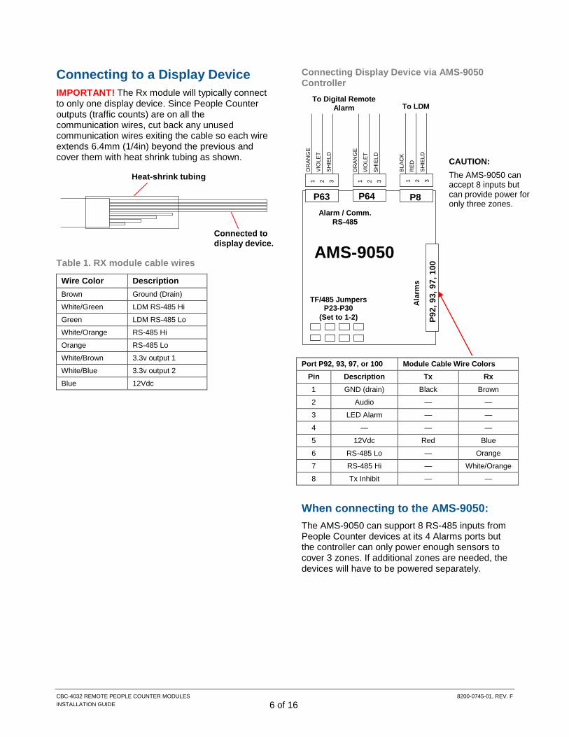
Connecting to a Display Device IMPORTANT! The Rx module will typically connect to only one display device. Since People Counter outputs (traffic counts) are on all the communication wires, cut back any unused communication wires exiting the cable so each wire extends 6.4mm (1/4in) beyond the previous and cover them with heat shrink tubing as shown.
Table 1. RX module cable wires
Wire Color Description Brown Ground (Drain)
White/Green LDM RS-485 Hi
Green LDM RS-485 Lo
White/Orange RS-485 Hi
Orange RS-485 Lo
White/Brown 3.3v output 1
White/Blue 3.3v output 2
Blue 12Vdc
Connecting Display Device via AMS-9050 Controller
Port P92, 93, 97, or 100 Module Cable Wire Colors Pin Description Tx Rx 1 GND (drain) Black Brown
2 Audio — —
3 LED Alarm — —
4 — — —
5 12Vdc Red Blue
6 RS-485 Lo — Orange
7 RS-485 Hi — White/Orange
8 Tx Inhibit — —
When connecting to the AMS-9050: The AMS-9050 can support 8 RS-485 inputs from People Counter devices at its 4 Alarms ports but the controller can only power enough sensors to cover 3 zones. If additional zones are needed, the devices will have to be powered separately.
Connected to display device.
Heat-shrink tubing
OR
ANG
E
VIO
LET
SHIE
LD
1 2 3
P63 P64 Alarm / Comm.
RS-485
To Digital Remote Alarm
P92,
93,
97,
100
Ala
rms
AMS-9050
TF/485 Jumpers P23-P30
(Set to 1-2)
CAUTION: The AMS-9050 can accept 8 inputs but can provide power for only three zones.
P8
1 2 3 1 2 3
OR
ANG
E
VIO
LET
SHIE
LD
BLAC
K
RED
SHIE
LD
To LDM

CBC-4032 REMOTE PEOPLE COUNTER MODULES 8200-0745-01, REV. F INSTALLATION GUIDE 7 of 16
Connecting to an UltraLink Requires two 5-pin, 3.81 pitch connectors. If unavailable, order AMS-9050 Connector Kit ZP9050-CONN and use two 5-pin, 3.81 pitch connectors included to connect the remote people counter modules. Follow the connection diagram below.
CBC-4032 UL (I/O Board)
Doo
r 1
Doo
r 2
TX
RX
TX
RX
Pin 1
Pin 16
Pin 2 Pin 4
Pin 2 Pin 1 Pin 4 Pin 5
Pin 10 Pin 12
Pin 10 Pin 9 Pin 12 Pin 13
TX Black (GND)
TX Red (12VDC)
RX Brown (GND)
RX Blue (12VDC)
RX White/Brown (3.3V output 1)
RX White/Blue (3.3V output 2)
TX Black (GND)
TX Red (12VDC)
RX Brown (GND)
RX Blue (12VDC)
RX White/Brown (3.3V output 1)
RX White/Blue (3.3V output 2)

CBC-4032 REMOTE PEOPLE COUNTER MODULES 8200-0745-01, REV. F INSTALLATION GUIDE 8 of 16
Connecting to a Local Device Manager (LDM) Note: These instructions only cover the connection of People Counter Modules to the power insertion hub. For connection to the network hub and LDM, see instructions included in the Power Insertion Kit and Local Device Manager.
Referring to Table 1 on page 6, and using the instructions below, do the following:
1. Detach the cover from the modular jack, then
attach cables from the transmit and receive People Counter Modules to the modular jack as follows: a. Connect the white/green wire from the
receive module to terminal 1. b. Connect the green wire from the receive
module to terminal 2. c. Move the green wire from terminal 5 to
terminal 4. d. Connect the blue wire from the receive
module and the red wire from the transmit module to terminal 4.
e. Move the brown wire from terminal 7 to terminal 8.
f. Connect the brown wire of the receive module and the black wire from the transmit module to terminal 8.
2. Cut back the unused communication wires as outlined in the “Connecting to a Display Device” section on page 6.
3. Reattach the jack cover.
4. Route a 0.9m (3ft) Cat5 cable from the modular jack to the power insertion hub using Cat5 standard T-568B. Note: Total cable length from the People Counter Modules to the power insertion hub cannot exceed 19.8m (65ft).
5. From the IP Address label sheet supplied with the LDM, affix a label to the jack and write the device address of the People Counter module on it.
8
1 2 4 BLU GRN WHT/GRN BRN RED BLK
RX
TX LDM Hub
Power Insertion
Hub TF
Modules
Power Insertion Jack
Cat5*
Cat5*
* Length limited by what Cat5 cable can handle.
19.8m (65ft) max
TF Connection Jack
Cat5
Power Supply
0.9m (3ft)
IMPORTANT! Make sure to move the pre-attached brown wire from terminal 7 to terminal 8, and the pre-attached green wire from terminal 5 to terminal 4.
8
1 2 4

CBC-4032 REMOTE PEOPLE COUNTER MODULES 8200-0745-01, REV. F INSTALLATION GUIDE 9 of 16
Connecting to an LDM via an AMS-9050 Controller 1. Using instructions supplied with the LDM, attach
the LDM to the AMS-9050 controller.
2. Refer to the “Connecting Display Device via AMS-9050” wiring diagram and connect the peripheral RS-485 from the RX module to the AMS-9050.
3. In the AMS-9050 controller, ensure jumpers P23 through P30 are set to 1-2 position.
4. Perform the procedures in “Setup and Verification” and “Mounting the Rx Module” and “Adjusting the IR Beams” on page 13 before continuing.
5. Verify software versions: • AMS-9050 software configurator is Version
2.01, build 409 or later. • On the configurator Flash Download screen,
confirm AMS-9050 controller firmware is version 1.9018 or later. In the Peripheral Device Download section, confirm People Counter board firmware is Version 5.5 or later.
6. Verify RS-485 communication: On the configurator Flash Download screen, click on the Peripheral Device Download dropdown menu. Each uniquely addressed People Counter device connected should be displayed.
7. Verify operation: Select Traffic Flow Mapping from the system menu. Each People Counter device should increment their corresponding “In Count” and “Out Count” display.
Connecting to a Digital Remote Alarm (DRA) via AMS-9050 Controller Installation 1. Referring to the “Connecting to a Display
Device” wiring diagram on page 6 and using instructions supplied with the alarm, attach the DRA to the AMS-9050 controller.
2. In the AMS-9050 controller, ensure jumpers P23 through P30 are set to 1-2 position.
3. Perform the procedures in “Setup and Verification” and “Mounting the Rx Module” and “Adjusting the IR Beams” on page 13 before continuing.
DRA Setup 1. Verify software versions:
• AMS-9050 software configurator is Version 2.01, build 409 or later.
• AMS-9050 controller firmware is version 1.9018 or later, and in the Peripheral Device Download section: DRA firmware is Version 5.5000 or later. Traffic Flow board firmware is Version 5.5 or later.
2. On the AMS-9050 Setup screen, select the Count Mode.
0 - Alarm Counts: Displays EAS alarm counts. Use AMS-9050 Alarm Mapping screen in the System menu to map alarm counts. People counts are tracked but not displayed.
CBC-4032 REMOTE PEOPLE COUNTER MODULES 8200-0745-01, REV. F INSTALLATION GUIDE 10 of 16
1 - People Counts: Displays people counts. Use the Traffic Flow Mapping screen to map people counts to each zone (doorway). EAS alarm counts are tracked but not displayed. Remote alarm zone mapping for people counts is independent from EAS alarm mapping. 2 - Toggle Counts: Displays people counts until EAS alarm is triggered, during which the display changes to EAS alarm counts for the duration of the alarm.
3. If the customer chooses to hear a chime when an “In Count/Out Count/Blocked sensor” event occurs, enable PC Chimes. a. On the Setup screen, check the “Enable PC
Chimes” box. b. On the Flash download screen, in the
Peripheral Device Download section, choose the appropriate DRA from the drop down list.
c. Choose “PC Chimes” in the Flash Type drop down list, and download the appropriate PC Chimes audio file.
Note: PC Chimes uses the first four seconds of an 18 second interval allowed for voice messages. If using a voice message with PC Chimes, you must load a new voice message that is no more than 14 seconds in length. If “Enable PC Chimes” is de-selected and a voice message is still being used, you must reload the voice message.
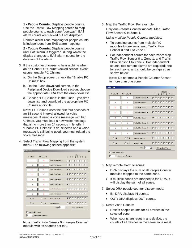
4. Select Traffic Flow Mapping from the system menu. The following screen appears:
Note: Traffic Flow Sensor 0 = People Counter module with its address set to 0.
5. Map the Traffic Flow. For example: Only one People Counter module: Map Traffic Flow Sensor 0 to Zone 1. Using multiple People Counter modules: • To combine counts from multiple RX
modules to one zone, map Traffic Flow Sensor 0 and 1 to Zone 1.
• For independent counts for each zone: Map Traffic Flow Sensor 0 to Zone 1, and Traffic Flow Sensor 1 to Zone 2. For independent counts, two remote alarms are required; one for each zone, and should be configured as shown below.
Note: Do not map a People Counter Sensor to more than one zone.
6. Map remote alarm to zones: • DRA displays the sum of all People Counter
modules mapped to the same zone. • If multiple zones are mapped to the DRA, it
will display the sum of all zones.
7. Select DRA people counter display mode. • IN: DRA displays IN counts. • OUT: DRA displays OUT counts.
8. Reset Zone Counts: • Resets people counts for all devices in the
selected zone. • When counts are reset in any device, the
counts of all devices in the same zone reset.

CBC-4032 REMOTE PEOPLE COUNTER MODULES 8200-0745-01, REV. F INSTALLATION GUIDE 11 of 16
Setup and Verification Note: The front cover of the Tx module should be already mounted and the front cover of the Rx module should be unattached so it can be adjusted during the verification process.
1. Apply power to the Tx and Rx modules and the display device.
2. On the front of each module, confirm the green power LEDs are illuminated.
3. On the circuit board of the Rx module, set the address using rotary switch S4 (if connecting directly to an LDM, switch S3 is also used). Use a unique address for each Rx module (0, 1, 2, and so on).
4. Place the Rx module in the path of the IR beam and confirm the amber LEDs are illuminated. These LEDs indicate that the Rx sensors are receiving the IR beams. Note: If unwanted IR from sources such as sunlight or neon signs interferes with reception, it may be necessary to swap the Tx and Rx modules so the receivers face away from the unwanted IR source. Note: LEDs may be above or below the emitters or receivers depending on module orientation.
5. With the Rx module in the path of the IR beam, confirm directionality of the system by observing LEDs on the circuit board of the receive module while someone walks between the modules (or you pass your hand in front of the Rx sensors). • DS2 (Red) = IN • DS3 (Green) = OUT If IN and OUT do not correspond to the doorway’s actual traffic flow, swap them by changing the position of dipswitch 2 on switch S5.
6. If connecting to an RS-485 device, confirm LEDs DS4-DS5 (peripheral) or DS6-DS7 (LDM) are illuminated.
7. If the modules are operating properly, mount the Rx module to the back cover, adjust the IR beams if necessary, and then reset the counter to zero.
S3
S4
DS6-DS7
DS4-DS5
DS2-DS3
S5

CBC-4032 REMOTE PEOPLE COUNTER MODULES 8200-0745-01, REV. F INSTALLATION GUIDE 12 of 16
Available LDM Addresses People Counter Address for LDM
RS-485 Device Address
Address Switch Settings
SW3 SW4 1 0 1 2 0 2 3 0 3 4 0 4 5 0 5 6 0 6 7 0 7
8-15 Not Allowed 16 1 0 17 1 1 18 1 2 19 1 3 20 1 4 21 1 5 22 1 6 23 1 7
24-30 Not Allowed 32 2 0 33 2 1 34 2 2 35 2 3 36 2 4 37 2 5 38 2 6 39 2 7
40-47 Not Allowed 48 3 0 49 3 1 50 3 2 51 3 3 52 3 4 53 3 5 54 3 6 55 3 7
56-63 Not Allowed
(Table, continued)
RS-485 Device Address
Address Switch Settings
SW3 SW4 64 4 0 65 4 1 66 4 2 67 4 3 68 4 4 69 4 5 70 4 6 71 4 7
72-79 Not Allowed 80 5 0 81 5 1 82 5 2 83 5 3 84 5 4 85 5 5 86 5 6 87 5 7
88-95 Not Allowed 96 6 0 97 6 1 98 6 2 99 6 3
100 6 4 101 6 5 102 6 6 103 6 7
104-111 Not Allowed 112 7 0 113 7 1 114 7 2 115 7 3 116 7 4 117 7 5 118 7 6
119 7 7

CBC-4032 REMOTE PEOPLE COUNTER MODULES 8200-0745-01, REV. F INSTALLATION GUIDE 13 of 16
Mounting the Rx Module Attach the top cover to the back cover using the two supplied screws. If the cable exits the top, bottom, or side of the module, use Wiremold to cover the cable.
Adjusting the IR Beams Are yellow LEDs on the Rx module off or flickering? If yes, do the following:
1. Verify nothing is blocking the IR beams.
2. Use the four alignment screws on the Tx module to adjust the beams until both amber LEDs on the Rx module are illuminated steady (do not over-tighten the screws). If required, repeat for the Rx module.
Resetting the Count to Zero The traffic flow count can be reset to zero using one of the following methods:
• Sensor Initiated Reset caused by successive IN-OUT-IN-OUT readings. To do this, quickly move an approximately 2.5cm (1in) wide object or two fingers back and forth five times in front of the IR receivers.
• Press switch S2 on the Rx module circuit board.
• Use the Reset Zone button on the Traffic Flow Mapping screen in the software configurator.
• Use the Reset button on the AMS-9050 software configurator Setup screen to reset all zones and peripheral devices.
Screws Front cover Back cover
S2
Alignment screws (4)

CBC-4032 REMOTE PEOPLE COUNTER MODULES 8200-0745-01, REV. F INSTALLATION GUIDE 14 of 16
Completing the Installation 1. Using the alcohol pad provided, thoroughly
clean the front surface of the module. Allow the surface to completely dry.
2. Attach a piece of double-sided tape to protective film on the appliqué and lift the tape to remove the film. Then peel adhesive backing from the appliqué.
3. With “Sensormatic” facing up, carefully align and insert the appliqué over the sensors.
Troubleshooting If the modules produce faulty or inconsistent counts after you properly align the modules and perform the verification process, there may be a multi-path issue. This occurs when the Rx module receives IR beams from the Tx module as well as IR reflected off of nearby surfaces. This may occur when the modules are mounted directly next to glass or metal, which can reflect the IR beams.
To correct the problem the modules must be readjusted away from the reflective surface.
1. Use the four alignment screws on the Tx module to adjust the beams away from the reflective surface while making sure the amber lights on the Rx remain on. To achieve maximum movement of the sensors, you can raise the alignment screws on one side while you lower on the other. Do not over-tighten the screws
2. Test performance of the system by moving an
opaque object at least 15cm x 15cm (6in x 6in) in size, like a piece of cardboard, between the modules at 30cm (1ft) increments.
3. If the problem still persists, use the four alignment screws on the Rx module to adjust the beams away from the reflective surface while making sure the amber lights remain on.
Clean
Remove protective film
Adhesive backing

CBC-4032 REMOTE PEOPLE COUNTER MODULES 8200-0745-01, REV. F INSTALLATION GUIDE 15 of 16
Specifications Electrical Type CBC-4032:
NEC Class 2, Certified Limited Power Source required Voltage ......................................................... 12–15Vdc Current ....................................................... 0.20A max.
Environmental Operating Temperature: ........... 0° to 40°C (32° to 104°F) Relative Humidity: .................... 0 to 90% non-condensing
Declarations Regulatory Compliance REG ID ............................................................ CBC-4032 EMC ........................................................ 47 CFR, Part 15 EN 55022 EN 55024 ICES-003 Safety: Complies with .................................... UL 60950-1 CSA C22.2.60950-1 EN 60950-1 IEC 60950-1 Environmental rating: IP20
FCC COMPLIANCE: This device complies with part 15 of the FCC Rules. Operation is subject to the following two conditions: (1) This device may not cause harmful interference, and (2) this device must accept any interference received, including interference that may cause undesired operation. NOTE: This equipment has been tested and found to comply with the limits for a Class A digital device, pursuant to part 15 of the FCC Rules. These limits are designed to provide reasonable protection against harmful interference when the equipment is operated in a commercial environment. This equipment generates, uses, and can radiate radio frequency energy and, if not installed and used in accordance with the instruction manual, may cause harmful interference to radio communications. Operation of this equipment in a residential area is likely to cause harmful interference in which case the user will be required to correct the interference at his own expense. CANADIAN COMPLIANCE: This Class A digital apparatus complies with Canadian ICES-003. Cet appareil numérique de la classe A est conforme à la norme NMB-003 du Canada. EQUIPMENT MODIFICATION CAUTION: Equipment changes or modifications not expressly approved by Sensormatic Electronics, LLC, the party responsible for FCC compliance, could void the user's authority to operate the equipment and could create a hazardous condition.
Other Declarations WARRANTY DISCLAIMER: Sensormatic Electronics, LLC makes no representation or warranty with respect to the contents hereof and specifically disclaims any implied warranties of merchantability or fitness for any particular purpose. Further, Sensormatic Electronics, LLC reserves the right to revise this publication and make changes from time to time in the content hereof without obligation of Sensormatic Electronics, LLC to notify any person of such revision or changes. LIMITED RIGHTS NOTICE: For units of the Department of Defense, all documentation and manuals were developed at private expense and no part of it was developed using Government Funds. The restrictions governing the use and disclosure of technical data marked with this legend are set forth in the definition of “limited rights” in paragraph (a) (15) of the clause of DFARS 252.227.7013. Unpublished - rights reserved under the Copyright Laws of the United States. TRADEMARK NOTICE: Sensormatic is a trademark or registered trademark of Sensormatic Electronics, LLC. Other product names mentioned herein may be trademarks or registered trademarks of Sensormatic or other companies. No part of this guide may be reproduced in any form without written permission from Sensormatic Electronics, LLC.

CBC-4032 REMOTE PEOPLE COUNTER MODULES 8200-0745-01, REV. F INSTALLATION GUIDE 16 of 16
Appendix A: Module Accessories Mounting Post (CBC-4030-Post)
Door-Max® Mounting Bracket (0404-0251-01)
Appendix B: Direct RS-232 Connections Set dip switches 5 and 6 on S5 to ON.
Connect using cable made in field (shown below)
1 2 3
Telephone Jack 1 2 3 4
3-pin Molex Shroud