Caution: This document contains mixed page sizes …n0nas/manuals/onan/981-0522B Onan HDKAJ...
93
Caution: This document contains mixed page sizes (8.5 x 11 or 11 x 17), which may affect printing. Please adjust your printer settings according to the size of each page you wish to print.
Transcript of Caution: This document contains mixed page sizes …n0nas/manuals/onan/981-0522B Onan HDKAJ...

Caution: This document contains mixed page sizes (8.5 x 11 or 11 x 17), which may affect printing. Please adjust your printer settings
according to the size of each page you wish to print.

HDKAJ, HDKAK, HDKAT
Printed in U.S.A. 981-0522B 7-99

California
Proposition 65 WarningDiesel engine exhaust and some of its constituents are knownto the State of California to cause cancer, birth defects, andother reproductive harm.
diesel warnings

Page 1 of 1
Supplement: 981-1049Date: 09/04Insert with-
Manual Number (Date): 981-0173 (08/04) 981-0174 (08/04) 981-0540 (08/04)981-0170 (11/03) 981-0171 (11/03) 981-0526D (02/04)981-0166B (06/03) 981-0167B (06/03) 981-0535 (10/02)981-0161 (08/89) 981-0522B (07/99)
Purpose: These instructions supplement the instructions for filling the engine cooling system found in thePeriodic Maintenance sections of the Operator’s and Service Manuals listed above.
WARNING To prevent severe burns from hot coolant under pressure, carefully observe all of theSafety Precautions and Instructions in the Manual for handling and filling coolant.
Instructions: Use a funnel when filling the cooling system through the fill opening (Figure 1) to preventcoolant from entering the vent hose and blocking the escape of air as the system fills. The system will seem fullwhen it actually is not if the air cannot escape through the vent hose. If the vent hose does get blocked, pinchthe overflow hose and blow the vent hose clear.
CAUTION Coolant trapped in the vent hose will prevent the system from filling to its capacity, whichcan lead to serious engine damage.
PRESSURE CAPAND SYSTEM FILL
OPENING
FIGURE 1. TYPICAL COOLANT FILL OPENING WITH CONNECTED FILL, OVERFLOW AND VENT HOSES

Table of Contents
i
SAFETY PRECAUTIONS iii. . . . . . . . . . . . . . . . . . . . . . . . . . . . . . . . . . . . . . . . . . . . . . . . . . . .
INTRODUCTION 1-1. . . . . . . . . . . . . . . . . . . . . . . . . . . . . . . . . . . . . . . . . . . . . . . . . . . . . . . . . . .
SPECIFICATIONS 2-1. . . . . . . . . . . . . . . . . . . . . . . . . . . . . . . . . . . . . . . . . . . . . . . . . . . . . . . . . .
THREAD TORQUES 3-1. . . . . . . . . . . . . . . . . . . . . . . . . . . . . . . . . . . . . . . . . . . . . . . . . . . . . . . .
OPERATION 4-1. . . . . . . . . . . . . . . . . . . . . . . . . . . . . . . . . . . . . . . . . . . . . . . . . . . . . . . . . . . . . . .
Fuel Recommendations 4-1. . . . . . . . . . . . . . . . . . . . . . . . . . . . . . . . . . . . . . . . . . . . . . . . .
Engine Oil Recommendations 4-1. . . . . . . . . . . . . . . . . . . . . . . . . . . . . . . . . . . . . . . . . . . .
Starting Batteries 4-1. . . . . . . . . . . . . . . . . . . . . . . . . . . . . . . . . . . . . . . . . . . . . . . . . . . . . . .
Operator’s Console 4-2. . . . . . . . . . . . . . . . . . . . . . . . . . . . . . . . . . . . . . . . . . . . . . . . . . . . .
Remote Control Panel 4-2. . . . . . . . . . . . . . . . . . . . . . . . . . . . . . . . . . . . . . . . . . . . . . . . . . .
Priming the Fuel System 4-3. . . . . . . . . . . . . . . . . . . . . . . . . . . . . . . . . . . . . . . . . . . . . . . . .
Starting 4-3. . . . . . . . . . . . . . . . . . . . . . . . . . . . . . . . . . . . . . . . . . . . . . . . . . . . . . . . . . . . . . . .
Stopping 4-3. . . . . . . . . . . . . . . . . . . . . . . . . . . . . . . . . . . . . . . . . . . . . . . . . . . . . . . . . . . . . . .
PERIODIC MAINTENANCE 5-1. . . . . . . . . . . . . . . . . . . . . . . . . . . . . . . . . . . . . . . . . . . . . . . . .
General Inspection 5-2. . . . . . . . . . . . . . . . . . . . . . . . . . . . . . . . . . . . . . . . . . . . . . . . . . . . . .
Checking Engine Oil Level 5-3. . . . . . . . . . . . . . . . . . . . . . . . . . . . . . . . . . . . . . . . . . . . . . .
Changing Engine Oil and Oil Filter 5-3. . . . . . . . . . . . . . . . . . . . . . . . . . . . . . . . . . . . . . . .
Spark Arrestor 5-5. . . . . . . . . . . . . . . . . . . . . . . . . . . . . . . . . . . . . . . . . . . . . . . . . . . . . . . . . .
Batteries 5-6. . . . . . . . . . . . . . . . . . . . . . . . . . . . . . . . . . . . . . . . . . . . . . . . . . . . . . . . . . . . . . .
Air Filter 5-6. . . . . . . . . . . . . . . . . . . . . . . . . . . . . . . . . . . . . . . . . . . . . . . . . . . . . . . . . . . . . . .
Fuel Filter 5-7. . . . . . . . . . . . . . . . . . . . . . . . . . . . . . . . . . . . . . . . . . . . . . . . . . . . . . . . . . . . . .
Changing Coolant 5-8. . . . . . . . . . . . . . . . . . . . . . . . . . . . . . . . . . . . . . . . . . . . . . . . . . . . . .
PREPARATIONS FOR SERVICE 6-1. . . . . . . . . . . . . . . . . . . . . . . . . . . . . . . . . . . . . . . . . . . . .
Special Tools 6-1. . . . . . . . . . . . . . . . . . . . . . . . . . . . . . . . . . . . . . . . . . . . . . . . . . . . . . . . . . .
Safety 6-1. . . . . . . . . . . . . . . . . . . . . . . . . . . . . . . . . . . . . . . . . . . . . . . . . . . . . . . . . . . . . . . . .
Removing the Genset from the Vehicle 6-2. . . . . . . . . . . . . . . . . . . . . . . . . . . . . . . . . . . .
Test Stand 6-2. . . . . . . . . . . . . . . . . . . . . . . . . . . . . . . . . . . . . . . . . . . . . . . . . . . . . . . . . . . . .
Removing and Installing the Housing Panels 6-3. . . . . . . . . . . . . . . . . . . . . . . . . . . . . . .
ENGINE AIR INTAKE SERVICE 7-1. . . . . . . . . . . . . . . . . . . . . . . . . . . . . . . . . . . . . . . . . . . . . .
MUFFLER SERVICE 8-1. . . . . . . . . . . . . . . . . . . . . . . . . . . . . . . . . . . . . . . . . . . . . . . . . . . . . . . .
Removal and Installation 8-1. . . . . . . . . . . . . . . . . . . . . . . . . . . . . . . . . . . . . . . . . . . . . . . . .
ENGINE COOLING SYSTEM SERVICE 9-1. . . . . . . . . . . . . . . . . . . . . . . . . . . . . . . . . . . . . . .
Radiator Removal and Installation 9-1. . . . . . . . . . . . . . . . . . . . . . . . . . . . . . . . . . . . . . . .
CONTROLLER/INVERTER SERVICE 10-1. . . . . . . . . . . . . . . . . . . . . . . . . . . . . . . . . . . . . . . .
Removal and Installation 10-1. . . . . . . . . . . . . . . . . . . . . . . . . . . . . . . . . . . . . . . . . . . . . . . .
Controller-Inverter Functions 10-3. . . . . . . . . . . . . . . . . . . . . . . . . . . . . . . . . . . . . . . . . . . .

ii
PMA (GENERATOR) SERVICE 11-1. . . . . . . . . . . . . . . . . . . . . . . . . . . . . . . . . . . . . . . . . . . . .
Stator Tests 11-1. . . . . . . . . . . . . . . . . . . . . . . . . . . . . . . . . . . . . . . . . . . . . . . . . . . . . . . . . . .
Stator Removal and Installation 11-3. . . . . . . . . . . . . . . . . . . . . . . . . . . . . . . . . . . . . . . . . .
Rotor Removal and Installation 11-3. . . . . . . . . . . . . . . . . . . . . . . . . . . . . . . . . . . . . . . . . .
ENGINE AND ACCESSORY SERVICE 12-1. . . . . . . . . . . . . . . . . . . . . . . . . . . . . . . . . . . . . .
Engine Service 12-1. . . . . . . . . . . . . . . . . . . . . . . . . . . . . . . . . . . . . . . . . . . . . . . . . . . . . . . .
Replacing the Coolant Pump Belt 12-1. . . . . . . . . . . . . . . . . . . . . . . . . . . . . . . . . . . . . . . .
Engine Sensors 12-1. . . . . . . . . . . . . . . . . . . . . . . . . . . . . . . . . . . . . . . . . . . . . . . . . . . . . . .
Engine Removal and Installation 12-2. . . . . . . . . . . . . . . . . . . . . . . . . . . . . . . . . . . . . . . . .
Replacing the Low Oil Pressure Cutoff Switch 12-2. . . . . . . . . . . . . . . . . . . . . . . . . . . . .
GOVERNOR ACTUATOR SERVICE 13-1. . . . . . . . . . . . . . . . . . . . . . . . . . . . . . . . . . . . . . . . .
Removal and Installation 13-1. . . . . . . . . . . . . . . . . . . . . . . . . . . . . . . . . . . . . . . . . . . . . . . .
Actuator Disassembly and Reassembly 13-4. . . . . . . . . . . . . . . . . . . . . . . . . . . . . . . . . . .
Actuator Speed Control Lever Stop (Beginning Spec B) 13-5. . . . . . . . . . . . . . . . . . . . .
High Idle Speed Adjustment 13-6. . . . . . . . . . . . . . . . . . . . . . . . . . . . . . . . . . . . . . . . . . . . .
High Idle Stop Screw Adjustment 13-7. . . . . . . . . . . . . . . . . . . . . . . . . . . . . . . . . . . . . . . .
FUEL SYSTEM SERVICE 14-1. . . . . . . . . . . . . . . . . . . . . . . . . . . . . . . . . . . . . . . . . . . . . . . . . .
Fuel Pump 14-1. . . . . . . . . . . . . . . . . . . . . . . . . . . . . . . . . . . . . . . . . . . . . . . . . . . . . . . . . . . .
Fuel Filter 14-1. . . . . . . . . . . . . . . . . . . . . . . . . . . . . . . . . . . . . . . . . . . . . . . . . . . . . . . . . . . . .
Fuel Injection System 14-1. . . . . . . . . . . . . . . . . . . . . . . . . . . . . . . . . . . . . . . . . . . . . . . . . .
BATTERY CHARGER SERVICE 15-1. . . . . . . . . . . . . . . . . . . . . . . . . . . . . . . . . . . . . . . . . . . .
Removal and Installation 15-1. . . . . . . . . . . . . . . . . . . . . . . . . . . . . . . . . . . . . . . . . . . . . . . .
STARTER MOTOR SERVICE 16-1. . . . . . . . . . . . . . . . . . . . . . . . . . . . . . . . . . . . . . . . . . . . . . .
Removal and Installation 16-1. . . . . . . . . . . . . . . . . . . . . . . . . . . . . . . . . . . . . . . . . . . . . . . .
Starter Solenoid Replacement 16-2. . . . . . . . . . . . . . . . . . . . . . . . . . . . . . . . . . . . . . . . . . .
SERVICE CHECKLIST 17-1. . . . . . . . . . . . . . . . . . . . . . . . . . . . . . . . . . . . . . . . . . . . . . . . . . . . .
TROUBLESHOOTING 18-1. . . . . . . . . . . . . . . . . . . . . . . . . . . . . . . . . . . . . . . . . . . . . . . . . . . . .
Fault Codes 18-1. . . . . . . . . . . . . . . . . . . . . . . . . . . . . . . . . . . . . . . . . . . . . . . . . . . . . . . . . . .
Bypassable Faults (Prior to Spec F) 18-1. . . . . . . . . . . . . . . . . . . . . . . . . . . . . . . . . . . . . .
Table 18-1. Troubleshooting 18-2. . . . . . . . . . . . . . . . . . . . . . . . . . . . . . . . . . . . . . . . . . . . .
ENGINE WIRING HARNESS 19-1. . . . . . . . . . . . . . . . . . . . . . . . . . . . . . . . . . . . . . . . . . . . . . .
AC WIRING HARNESS 19-2. . . . . . . . . . . . . . . . . . . . . . . . . . . . . . . . . . . . . . . . . . . . . . . . . . . .
BATTERY WIRING HARNESS 19-3. . . . . . . . . . . . . . . . . . . . . . . . . . . . . . . . . . . . . . . . . . . . . .
WIRING DIAGRAM 19-4. . . . . . . . . . . . . . . . . . . . . . . . . . . . . . . . . . . . . . . . . . . . . . . . . . . . . . . .

iii
Safety Precautions
Thoroughly read the OPERATOR’S MANUAL be-fore operating the genset. Safe operation and topperformance can be obtained only with properoperation and maintenance.
The following symbols in this Manual alert you to po-tential hazards to the operator, service person andequipment.
Alerts you to an immediate hazardwhich will result in severe personal injury ordeath.
WARNING Alerts you to a hazard or unsafe prac-tice which can result in severe personal injury ordeath.
CAUTION Alerts you to a hazard or unsafe prac-tice which can result in personal injury or equip-ment damage.
Electricity, fuel, exhaust, moving parts and batteriespresent hazards which can result in severe personalinjury or death.
GENERAL PRECAUTIONS
• Keep ABC fire extinguishers handy.
• Make sure all fasteners are secure and torquedproperly.
• Keep the genset and its compartment clean. Ex-cess oil and oily rags can catch fire. Dirt and gearstowed in the compartment can restrict coolingair.
• Let the engine cool down before removing thecoolant pressure cap or opening the coolantdrain. Hot coolant under pressure can spray outand cause severe burns.
• Before working on the genset, disconnect thenegative (–) battery cable at the battery to pre-vent starting.
• Use caution when making adjustments while thegenset is running—hot, moving or electricallylive parts can cause severe personal injury ordeath.
• Used engine oil has been identified by somestate and federal agencies as causing cancer orreproductive toxicity. Do not ingest, inhale, orcontact used oil or its vapors.
• Benzene and lead in some gasolines have beenidentified by some state and federal agencies ascausing cancer or reproductive toxicity. Do not toingest, inhale or contact gasoline or its vapors.
• Do not work on the genset when mentally orphysically fatigued or after consuming alcohol ordrugs.
• Carefully follow all applicable local, state andfederal codes.
GENERATOR VOLTAGE IS DEADLY!
• Generator output connections must be made bya qualified electrician in accordance with appli-cable codes.
• The genset must not be connected to the publicutility or any other source of electrical power.Connection could lead to electrocution of utilityworkers, damage to equipment and fire. An ap-proved switching device must be used to preventinterconnections.
• Use caution when working on live electricalequipment. Remove jewelry, make sure clothingand shoes are dry and stand on a dry woodenplatform on the ground or floor.
FUEL IS FLAMMABLE AND EXPLOSIVE
• Keep flames, cigarettes, sparks, pilot lights,electrical arc-producing equipment and switchesand all other sources of ignition well away fromareas where fuel fumes are present and areassharing ventilation.
• Fuel lines must be secured, free of leaks andseparated or shielded from electrical wiring.
• Use approved non-conductive flexible fuel hosefor fuel connections at the genset.

iv
ENGINE EXHAUST IS DEADLY!
• Learn the symptoms of carbon monoxide poi-soning in this Manual.
• Never sleep in the vehicle while the genset isrunning unless the vehicle has a working carbonmonoxide detector.
• The exhaust system must be installed in accor-dance with the genset Installation Manual.
• Do not use engine cooling air to heat the vehicleinterior.
• Make sure there is ample fresh air when operat-ing the genset in a confined area.
MOVING PARTS CAN CAUSE SEVEREPERSONAL INJURY OR DEATH
• Do not wear loose clothing or jewelry near mov-ing parts such as PTO shafts, fans, belts and pul-leys.
• Keep hands away from moving parts.
• Keep guards in place over fans, belts, pulleys,etc.
BATTERY GAS IS EXPLOSIVE
• Wear safety glasses and do not smoke while ser-vicing batteries.
• When disconnecting or reconnecting batterycables, always disconnect the negative (–) bat-tery cable first and reconnect it last to reduce arc-ing.
DO NOT OPERATE IN FLAMMABLE ANDEXPLOSIVE ENVIRONMENTS
Flammable vapor can cause a diesel engine to over-speed and become difficult to stop, resulting in pos-sible fire, explosion, severe personal injury anddeath. Do not operate a diesel-powered gensetwhere a flammable vapor environment can becreated by fuel spill, leak, etc., unless the gensetis equipped with an automatic safety device toblock the air intake and stop the engine. The own-ers and operators of the genset are solely responsi-ble for operating the genset safely. Contact your au-thorized Onan/Cummins dealer or distributor formore information.
Mobile-3

1. Introduction
1-1
This is the Service Manual for the HDKAJ, HDKAKand HDKAT Series of generator sets (gensets).Read and carefully observe all of the instructionsand precautions in this manual.
WARNING Improper service or parts replace-ment can lead to severe personal injury or deathand to damage to equipment and property. Ser-vice personnel must be qualified to performelectrical and mechanical service.
CAUTION Unauthorized modifications or re-placement of fuel, exhaust, air intake or speedcontrol system components that affect engineemissions are prohibited by law in the State ofCalifornia.
See the Installation Manual for important recom-mendations concerning the installation and for a listof the installation codes and standards for safetywhich may be applicable.
See the Parts Catalog for parts identification num-bers and required quantities. Genuine Onan re-placement parts are recommended for best results.
When contacting Onan for parts, service or productinformation, be ready to provide the model numberand the serial number, both of which appear on thegenset nameplate. Figure 1-1 illustrates the name-plate and its location. The numbers in the grayboxes are typical model and serial numbers. Everycharacter in these numbers is significant. (The lastcharacter of the model number is the specificationletter, which is important for obtaining the rightparts.)
SKB719U6D2RA 719 cc
80HDKAK11454JF990 123456
FIGURE 1-1. TYPICAL NAMEPLATE

1-2
COOLANTRECOVERY
TANK
RADIATOR
CONTROLLER/INVERTERHOUSING
INTAKE AIRRESONATOR
STARTERMOTOR
GENERATOR(PMA) STATOR
INNERBULKHEAD
ENGINE
COOLINGBLOWER
GOVERNORACTUATOR
COOLANTPRESSURE
CAP
FUELFILTER
OILFILTER
FUELPUMP
MUFFLERASSEMBLY
FIGURE 1-2. TYPICAL GENSET WITH HOUSING PANELS REMOVED

2. Specifications
2-1
Model HDKAJ / HDKAT Model HDKAK
GENSET CONTROLLER: Integrated Microprocessor Based Engine and Generator Controller
GENERATOR: Brushless, Exciterless, Bearingless, Permanent Magnet Alternator
AC OUTPUT RATINGS:Power (@1.0 power factor) 7500 W 8000 W
Voltage 120 volts 120 volts
Frequency 60 Hz 60 Hz
Number of Phases 1 1
Current 62.5 ampere 66.7 ampere
Line Circuit Breaker(s) One 2-pole, 30 or 35 amp One 2-pole, 30 or 35 amp
ENGINE: 3-Cylinder In-Line, Water-Cooled, Indirect-Injection, 4-Stroke Cycle DieselBore 2.64 inch (67 mm)
Stroke 2.68 inch (68 mm)
Displacement 44 inch3 (719 cc)
Compression Ratio 23 : 1
Oil Capacity (with filter)* 3 quart (2.6 l)Cooling System Capacity** 4.2 quart (4 l)Intake and Exhaust Valve Lash (Cold) 0.0065 inch (0.165 mm)
OPERATING SPEED RANGE: 1600 to 3200 RPM (HDKAJ)2300 to 3200 RPM (HDKAT) 1600 to 3300 RPM
FUEL CONSUMPTION:
No-loadHalf-load (4000 W)Full-load
.13 gph (.49 l/h)
.49 gph (1.85 l/h)
.96 gph (3.63 l/h)
.13 gph (.49 l/h)
.49 gph (1.85 l/h)
1.02 gph (3.86 l/h)
DC SYSTEM:Nominal Battery Voltage 12 voltsMinimum Battery CapacityCCA (Cold Cranking Amps)
450 ampere down to 0° F (–17° C)650 ampere down to –20° F (–29° C)
Maximum Regulated-Voltage BatteryCharging Current (Optional) 10 ampere
Fuse F1 (control circuit) 10 ampere mini-bayonetFuse F2 (starter solenoid circuit) 10 ampere mini-bayonetFuse F3 (glow plug circuit) 25 ampere
WEIGHT AND SIZE:
Weight (wet)Length x Width x Height
420 lbs (191 kg)
36.3 x 23.6 x 22.3 inch (922 x 599 x 566 mm)* See CHANGING ENGINE OIL AND OIL FILTER, Page 5-3, for oil filling instructions.** Includes coolant recovery tank.

2-2

3. Thread Torques
3-1
lbf-ft* N-m *
Air Cleaner Cover Bolt—Three to four clicks past seating. – –
Air Cleaner Housing Mounting Screws 7-9 10-12
Intake Air Hose Clamp Screws 7-9 10-12
Air Intake Resonator Mounting Screws 7-9 10-12
Fuel Pump Mounting Screws 75-80 lbf-inch 8.5-9
Fuel Fitting At Fuel Pump 7-9 10-12
Fuel Fittings at Fuel Filter—One flat passed finger tight. – –
Exhaust Assembly Flange Bolts 16-20 22-28
Exhaust Isolator Clamp Screws 7-9 10-12
Housing Panel Screws 11-13 15-18
Component Mounting Screws (threads into skid-base) 7-9 10-12
Vibration Isolator Center Bolt 43-53 58-72
Vibration Isolator Mounting Screws 7-9 10-12
Battery Cable Terminal Block Terminal Nuts 6.7-8.3 9-11
Battery Cable Terminal Block Mounting Screws 7-9 10-12
Starter Solenoid Terminal Nuts 4.4-8.7 5.9-11.8
AC Output Terminal Block Terminal Screws 12-14 lbf-inch 1.4-1.6
AC Output Terminal Block Mounting Screws 20-22 lbf-inch 2.2-2.5
Circuit Breaker Terminal Screws 12-14 lbf-inch 1.4-1.6
Circuit Breaker Mounting Screws 12-14 lbf-inch 1.4-1.6
Flywheel Housing Mounting Bolts 18-22 24-30
Rotor/Flywheel Mounting Bolts 40-43 53.9-58.8
Stator Mounting Bolts 7-9 10-12
Blower Mounting Bolts 7-9 10-12
Starter Mounting Bolts 18-22 24-30
Oil Pan Mounting Bolts 5.8-6.9 7.9-9.3
Coolant Temperature Sender (use thread sealant) 26-32 35-43
Low Oil Pressure Switch (use thread sealant) 10.8-14.5 14.7-19.6
Governor Actuator Bearing Carrier Mounting Screws 21-27 lbf-inch 2.4-3.0
Oil Fill Hose Support Clip Screw 7-9 10-12
M6 Engine Bolts Except When Otherwise Specified 5.8-6.9 7.9-9.3
M8 Engine Bolts Except When Otherwise Specified 13.0-15.2 17.7-20.6
M10 Engine Bolts Except When Otherwise Specified 28.9-33.3 39.2-45.1
M12 Engine Bolts Except When Otherwise Specified 46.3-53.5 62.8-72.6
* – Use engine oil as a lubricant for all threads except when otherwise specified.

3-2

4. Operation
4-1
FUEL RECOMMENDATIONS
Use clean, fresh No. 2 diesel fuel (ASTM 2-D) inambients above freezing and No. 1 diesel fuel(ASTM 1-D) in ambients below freezing. The fuelshould have a Cetane number of at least 45 for reli-able starting.
WARNING Diesel fuel is combustible and cancause severe personal injury or death. Do notsmoke near diesel fuel tanks or equipment.Keep flames, sparks, pilot lights, electrical arcsand arc-producing equipment and switchesand all other sources of ignition well away. Keepa type ABC fire extinguisher in the vehicle.
ENGINE OIL RECOMMENDATIONS
Use API (American Petroleum Institute) perfor-mance Class CH-4, CG-4 or CF-4D engine oil,which may be in combination with performanceClass SJ, SH or SG (for example: CH-4/SJ). Also
look for the SAE (Society of Automotive Engineers)viscosity grade. Referring to Chart 4-1, choose theviscosity grade appropriate for the ambient temper-atures expected until the next scheduled oilchange.
STARTING BATTERIES
These gensets have a 12 volt, direct current (DC)starting and control system. See Specifications forminimum battery requirements (cold cranking am-peres) for genset starting.
Regular, monthly maintenance of batteries may berequired. See Periodic Maintenance, and any in-structions available from the vehicle manufactureror battery manufacturer. Either the vehicle or thegenset will be equipped with a battery charger.
Reliable genset starting and starter service life de-pend upon adequate battery system capacity andproper maintenance.
CHART 4-1. OIL VISCOSITY VS. TEMPERATURE
Anticipated Ambient Temperature

4-2
OPERATOR’S CONSOLE
The operator’s console (Figure 4-1) has the follow-ing features:
Control Switch – This switch is used to start andstop the genset, prime the engine fuel system andrestore the fault code (blinking status light).
Status Light – This is an LED (light emitting diode)in the control switch which blinks rapidly during pre-heat and cranking. (Preheat is the period of timeprior to engine cranking when the glow plugs pre-heat the combustion chambers. The time is auto-matically varied by the genset controller on the ba-sis of engine temperature.) After the genset startsup, this light stays on continuously, indicating thatthe genset is running and that the starter has dis-connected. Also, if the genset shuts down, this lightblinks in a coded fashion to indicate the nature of theshutdown. See Troubleshooting.
Line Circuit Breaker(s) – The line circuit break-er(s) protect the AC power leads connected to thegenset.
Engine Oil Fill Cap/Dipstick – The oil dipstick is at-tached to the fill cap and is marked ADD and FULL.
Coolant Recovery Tank Fill Cap – The recoverytank provides for coolant expansion. Replenish thenormal loss of coolant by filling here.
Coolant Pressure Cap – The coolant pressure capis accessible by removing the access plate on thecontrol console. It provides for a pressurized enginecooling system. Fill coolant here when refilling thesystem.
Fuses F1, F2 and F3 – These fuses are accessibleby removing the access plate on the control con-sole. They protect the control circuits of the genset.
REMOTE CONTROL PANEL
The vehicle may be equipped with a remote controlpanel having a Control Switch and Preheat/Diag-nostics Light . In addition, it may have an hour me-ter and the following engine gauges:
Oil Pressure Gauge – The oil pressure gauge indi-cates the presence of engine oil pressure.
Water Temperature Gauge – The water tempera-ture gauge indicates engine coolant temperature.
Voltmeter – The voltmeter indicates battery volt-age.
ACCESSPLATE
COOLANTRECOVERY TANKFILL CAP (BLUE)
OIL FILL CAPAND DIP STICK
(YELLOW)
LINE CIRCUITBREAKER
HOUR METER(OPTIONAL)
CONTROLSWITCH AND
STATUS LIGHT
FIGURE 4-1. OPERATOR’S CONSOLE

4-3
WARNING EXHAUST GAS IS DEADLY!
All engine exhaust contains carbon monoxide, an odorless, colorless, poisonous gas that can causeunconsciousness and death. Symptoms of carbon monoxide poisoning include:
• Dizziness • Headache• Nausea • Weakness and Sleepiness• Vomiting • Inability to Think Coherently
IF YOU EXPERIENCE ANY OF THESE SYMPTOMS, GET INTO FRESH AIR IMMEDIATELY. If symptomspersist, seek medical attention. Shut down the genset and do not operate it until it has been inspectedand repaired.
Never sleep in the vehicle while the genset is running unless the vehicle has a working carbon monox-ide detector. The exhaust system must be installed in accordance with the genset Installation Manual.Make sure there is ample fresh air when operating the genset in a confined area.
PRIMING THE FUEL SYSTEM
The fuel system should be primed after replacingthe fuel filter or running the genset out of fuel. Toprime the fuel system hold the control switch downin its Stop position for at least 1 minute.
STARTING
The genset can be started and stopped from thegenset control panel or from a remote control panelinside the vehicle.
1. Review Powering Equipment, Varying Operat-ing Conditions, Genset Break-In, Exercise andStorage and the Maintenance Record in theOperator’s Manual before starting or servicingthe genset.
2. Check fuel, oil and coolant levels, prime thefuel system if necessary (by pushing the Stopswitch), and turn off the air conditioner(s) andother large electrical loads.
3. Push the control switch to its Start position andhold it there while the status light blinks rapidlyindicating preheat. Let go when the light comeson continuously, indicating that the genset isrunning and that the starter has been discon-nected. (Depending on how cold it is, preheatcan take up to 15 seconds, extending the timethat the light blinks.)
CAUTION Excessive cranking can over-heat and damage the starter motor. Do notcrank for more than 30 seconds at a time.Wait at least 2 minutes before trying again.
4. See Troubleshooting if the genset does notstart after three tries.
5. Let the genset warm up a few minutes until it isrunning smoothly before connecting the ve-hicle electrical loads (appliances).
6. Monitor the engine gauges if the remote panelis so equipped. Normal readings during opera-tion are as follows:
Oil Pressure: Approximately center of scale
Temperature: 160°-220° F (71°-104° C)
DC Voltage: 14-15 volts.
7. Check for fuel, coolant and exhaust leaks. Stopthe genset immediately if there is a fuel, coolantor exhaust leak and repair it before continuingoperation.
STOPPING
Run the genset at no load for a few minutes to allowthe engine to cool down and then push the controlswitch briefly to its Stop position.

4-4

5. Periodic Maintenance
5-1
Periodic maintenance is essential for top perfor-mance and long genset life. Use Table 5-1 as aguide for normal periodic maintenance. Under hot
or dusty operating conditions some maintenanceoperations should be performed more frequently,as indicated by the footnotes in the table.
TABLE 5-1. PERIODIC MAINTENANCE SCHEDULE
MAINTENANCE FREQUENCY
MAINTENANCE OPERATION EveryDay
EveryMonth
Every150 Hours
Every500 Hours
Every1000 Hours
Page
General Inspection • 5-2
Check Engine Oil Level • 5-3
Check Engine Coolant Level • 5-8
Clean and Check Battery •3 5-6
Change Engine Oil and Filter •1, 2, 3, 4 5-3
Clean Spark Arrestor •4 5-5
Replace Engine Air Filter •2, 4 5-6
Replace Fuel Filter •4 5-7
Check Coolant Anti-freeze Protection •4 5-8
Flush Coolant System •5 5-8
Replace Coolant Pressure Cap •5 5-8
Replace Engine V-belt •6,7 12-1
Clean Crankcase Breather •6,7 12-1
Replace Coolant Hoses and Thermostat •6, 7 9-1
1 – As a part of engine break-in, change the engine oil and oil filter after the first 50 hours of operation.2 – Perform more often when operating in dusty conditions.3 – Perform more often when operating in hot weather.4 – Perform at least once a year.5 – Perform at least once every two years.6 – Perform at least once every five years.7 – Must be performed by a qualified mechanic (authorized Onan dealer).

5-2
GENERAL INSPECTION
Inspect the genset before the first start of the day.
Oil Level
Check engine oil level (p. 5-3).
Engine Coolant System
Check the coolant level and look for coolant leaksaround the bottom of the genset and on the groundbelow. Minor leaks that can be replenished by dailyadditions of coolant to the recovery tank should berepaired by a qualified service technician as soonas possible. Larger leaks are cause for shuttingdown the genset until it can be repaired.
CAUTION Operating the genset when thecoolant level is low can cause serious enginedamage.
Exhaust System
Look and listen for exhaust system leaks while thegenset is running. Shut down the genset if a leak isfound and have it repaired before operating thegenset.
Look for openings or holes between the gensetcompartment and vehicle cab or living space if thegenset engine sounds louder than usual. Have allsuch openings or holes closed off and sealed to pre-vent exhaust gases from entering the vehicle.
Replace dented, bent or severely rusted sections ofthe tailpipe and make sure the tailpipe extends atleast 1 inch (25.4 mm) beyond the perimeter of thevehicle.
Park the vehicle so that the genset exhaust gasescan disperse away from the vehicle. Barriers suchas walls, snow banks, high grass and brush andother vehicles can cause exhaust gases to accumu-late in and around the vehicle.
Do not operate power ventilators or exhaust fanswhile the vehicle is standing with the genset run-ning. The ventilator or fan can draw exhaust gasesinto the vehicle.
WARNING EXHAUST GAS IS DEADLY! Do notoperate the genset if there is an exhaust leak orany danger of exhaust gases entering or beingdrawn into the vehicle.
WARNING Do not park the vehicle in highgrass or brush. Contact with the exhaust sys-tem can cause a fire.
Fuel System
Look for fuel leaks around the bottom of the gensetand its fuel supply lines when the genset is running.Do not operate the genset if there is a fuel leak.Have the leaks fixed as soon as possible.
WARNING Diesel fuel leaks can lead to fire. Donot operate the genset if operation causes fuelto leak.
Mechanical
Look for mechanical damage. Start the genset andlook, listen and feel for any unusual noises andvibrations.
Check the genset mounting bolts to make sure theyare secure.
Check to see that the genset air inlet and outletopenings are not clogged with debris or blocked.
Check the engine gauges from time to time whilethe genset is running (if so equipped).
Battery Connections
Check the battery terminals for clean, tight connec-tions. See BATTERIES (p. 5-6).
WARNING Arcing at battery terminals, lightswitch or other equipment, flame, and sparkscan ignite battery gas causing severe personalinjury.
Ventilate battery area before working on or nearbattery—Wear safety glasses—Do not smoke—Switch trouble light ON or OFF away from bat-tery—Stop genset and disconnect charger be-fore disconnecting battery cables—Disconnectnegative (–) cable first and reconnect last.

5-3
CHECKING ENGINE OIL LEVEL
Shut off the genset before checking the engine oillevel.
1. Remove the oil fill cap (yellow) and wipe thestick clean (Figure 5-1).
2. Screw the oil fill cap back on and remove it tocheck the oil level on the dipstick.
3. Add oil as necessary until the full mark isreached. See ENGINE OIL RECOMMEN-DATIONS (p. 4-1).
DO NOT FILL TO A LEVEL ABOVE THE FULLMARK ON THE DIPSTICK. Drain the excessoil if too much has been added.
CAUTION Too much oil can cause high oilconsumption, high operating temperaturesand oil foaming. Too little oil can cause se-vere engine damage. Keep the oil level be-tween the Full and Add marks on the dip-stick.
4. Screw the oil fill cap on securely to prevent oilleakage.
CHANGING ENGINE OIL AND OIL FILTER
Refer to Table 5-1 for scheduled engine oil change.In hot weather and dusty conditions the oil shouldbe changed more often.
WARNING State and federal agencies have de-termined that contact with used engine oil cancause cancer or reproductive toxicity. Take careto limit skin contact and breathing of vapors asmuch as possible. Use rubber gloves and washexposed skin.
1. Place a pan under the oil drain plug. Run theengine until it is warm and shut it off.
2. Remove the oil fill cap (Figure 5-1).
3. Unscrew the oil drain plug (Figure 5-2) and al-low all of the oil to drain from the engine.
4. Reinstall the oil drain plug and tighten it secure-ly to prevent oil leakage.
FIGURE 5-1. OIL DIPSTICK

5-4
5. Squeeze the access door latches together andlet the door swing down (Figure 5-2). Spin offthe oil filter canister, drain it of oil and discardit according to local regulations.
6. Thoroughly wipe off the filter mounting surface.Remove the old gasket if it does not come offwith the filter canister.
7. Make sure the new gasket is in place on thenew filter canister and apply a thin film of oil tothe gasket. (The replacement filter canister has
a larger diameter than the original filter cannis-ter, but will fit.)
8. Spin on the new filter canister by hand until thegasket just touches the mounting pad and thenturn it an additional 1/2 to 3/4 turn. Do not over-tighten. Close the access door, making sure itlatches securely.
9. Refill and check the oil level. See Specifica-tions for oil capacity.
10. Dispose of the used oil properly.
OIL DRAINPLUG
OILFILTER
ACCESSDOOR
FIGURE 5-2. OIL DRAIN PLUG AND OIL FILTER

5-5
SPARK ARRESTOR
Refer to Table 5-1 for scheduled cleaning of thespark arrestor muffler (which meets U.S. ForestService requirements). Cleaning is required formaximum genset performance.
WARNING A hot muffler can cause severeburns. Let the muffler cool down before remov-ing or installing the cleanout plug.
The muffler is mounted inside the genset housing.The cleanout plug is located on the side of the muf-
fler, accessible through the air outlet opening in thebottom of the genset. Clean out the spark arrestormuffler as follows:
1. Remove the cleanout plug from the muffler(Figure 5-3).
2. Restart the genset and load it nearly to full pow-er. Let the genset run for about five minutes toexpel the soot in the muffler.
3. Stop the genset, allow the muffler to cool downand then reinstall the plug.
CLEANOUTPLUG
FIGURE 5-3. SPARK ARRESTOR CLEANOUT PLUG

5-6
BATTERIES
WARNING Arcing at battery terminals, lightswitch or other equipment, flame, and sparkscan ignite battery gas causing severe personalinjury.
Ventilate battery area before working on or nearbattery—Wear safety glasses—Do not smoke—Switch trouble light ON or OFF away from bat-tery—Stop genset and disconnect charger be-fore disconnecting battery cables—Disconnectnegative (–) cable first and reconnect last.
Refer to Table 5-1 for scheduled battery mainte-nance, and follow the battery manufacturer’s in-structions. Have the battery charging system ser-viced if DC system voltage is consistently low orhigh. Always:
1. Keep the battery case and terminals clean anddry and the terminals tight.
2. Remove battery cables with a battery terminalpuller.
3. Make sure which terminal is positive (+) andwhich is negative (–) before making batteryconnections, always removing the negative (–)cable first and reconnecting it last to reducearcing.
AIR FILTER
Refer to Table 5-1 for scheduled air filter replace-ment. In dusty conditions the air filter elementshould be inspected and changed more frequentlyfor best operation. To change the air filter element,remove the outer and inner covers (Figure 5-4) andreassemble with a new air filter element. Turn the in-ner cover wingnut three to four clicks past seating.Make sure the outer cover is seated before tighten-ing its wingnut Check for noise when the gensetis running, and retighten if necessary.
OUTER COVER INNER COVER FILTER ELEMENT SPACER SEAL HOUSING
FIGURE 5-4. AIR FILTER ELEMENT

5-7
FUEL FILTER
Refer to Table 5-1 for scheduled replacement of thefuel filter (Figure 5-5). A dirty fuel filter may be thecause if the engine fails to start. The fuel filter is ac-cessible through the maintenance access door inthe skid-base. Squeeze the latches together toopen the door.
CAUTION Wipe the dirt off the fuel fittings be-fore disconnecting them to keep dirt from enter-ing the fuel system.
WARNING Diesel fuel is combustible and cancause severe personal injury or death. Do notsmoke. Keep flames, sparks, pilot lights, electri-cal arcs and arc-producing equipment and allother sources of ignition well away. Keep a typeABC fire extinguisher handy.
Removing the Fuel Filter: To remove the filter, dis-connect the two fittings at the filter and remove themounting nut. Apply a wrench on the filter fitting aswell as on the flare nut so as not to stress the fitting.Flare nut wrenches should be used on the flare nutsso as not to round the corners on the nuts. Disposeof the fuel filter according to local regulations.
Installing the Fuel Filter: Rotate the filter half aturn around its mounting stud if the fittings interferewith the bracket. It only fits properly one way.
Connect the fuel fittings before tightening the filtermounting nut. Take care not to crossthread the fuelfittings. Thread them in by hand and tighten one flatpast seating.
Close the access door and prime the fuel system byholding the control switch down in its Stop positionfor at least 1 minute. Priming is necessary to dis-place the air in the new filter with fuel.
FILTERMOUNTING
NUT
TUBING FROMFUEL PUMP
FUEL HOSETO ENGINE
FUELFILTER
FIGURE 5-5. FUEL FILTER

5-8
CHANGING COOLANT
Refer to Table 5-1 for scheduled maintenance. Theengine cooling system is filled with a 50/50 mixtureof ethylene glycol anti-freeze and water when thegenset leaves the factory, which is suitable for tem-peratures down to -34° F (-37° C).
Replace the coolant every two years. Use ethyleneor propylene glycol anti-freeze solution that con-tains a rust and corrosion inhibitor. The anti-freezemust not contain a stop-leak additive.
The water used for engine coolant must be clean,low in minerals, and free of corrosive chemicals.Use distilled water if available.
See Specifications for cooling system capacity.
Pressure Cap
Replace the pressure cap every two years becauseits seals can deteriorate and begin to leak. Propercooling system pressure (14 psi) is essential for op-timal engine cooling and minimal coolant loss.
Draining the Cooling System
WARNING Hot coolant spray can cause severeburns. Let the engine cool before releasing thepressure cap or removing the drain cap.
Allow the engine to cool before removing the pres-sure cap. Then relieve any remaining pressure byturning the pressure cap slowly, without pushingdown on it, until it catches. When the pressure hasbeen relieved, remove the pressure cap by pushing
down and turning it until it can be withdrawn. Thenget a suitable container and drain the coolant by re-moving the system drain cap (Figure 5-6).
WARNING Ethylene glycol antifreeze is con-sidered toxic. Dispose of it according to localregulations for hazardous substances.
It is recommended that the system be cleaned andflushed before refilling. Radiator cleaning chemi-cals are available at local auto parts stores. Followthe instructions for cleaning and flushing that comewith the cleaning solution.
Refilling the Cooling System
Fill the recovery tank with coolant mixture to theCOLD mark.
Secure the system drain cap. Fill the cooling systemwith coolant mixture through the pressure cap/fillopening. Pull the hose connected to the pressurecap assembly out as far as it will go. When coolantfills up to the fill opening, start and operate the gen-set for a few minutes and shut it down. (It is recom-mended that the air conditioners or other largeloads be turned on so that the genset will operateunder load, causing the engine to run faster and ex-pel trapped air.) Add more coolant if necessary andsecure the pressure cap.
Coolant Level Check
Check coolant level in the recovery tank before thefirst startup of each day and fill to the COLD mark ifnecessary.

5-9
PRESSURE CAPAND SYSTEM FILL
OPENING
COOLINGSYSTEM
DRAIN CAP
COOLANT RECOVERYTANK FILL CAP (BLUE)
FIGURE 5-6. ENGINE COOLING SYSTEM FILL AND DRAIN CAPS

5-10

6. Preparations for Service
6-1
SPECIAL TOOLS
The following tools are necessary for servicing thegenset:
Torque wrench: 0-75 lbs-ft (0-100 N-m)
Tachometer
Digital multi-meter: AC and DC Voltage, Ohms
Load test panel and leads
SAFETY
There are hazards in servicing gensets. StudySafety Precautions and become familiar with thehazards listed in Table 6-1. Note the following safe-guards and ways of avoiding hazards:
• Use personal protection: Wear appropriateprotective safety equipment, such as safetyshoes and safety glasses.
Do not wear rings or jewelry and do not wearloose or damp clothing that might get caught inequipment or conduct electricity.
• Reduce the hazard: A safe, orderly workshoparea and well-maintained equipment reducethe hazard potential. Keep guards and shieldsin place on machinery and maintain equipmentin good working condition. Store flammable liq-uids in approved containers; away from fire,flame, spark, pilot light, switches, arc-produc-ing equipment and other ignition sources. Keepthe workshop clean and well-lighted and pro-vide adequate ventilation.
• Develop safe work habits: Unsafe actionscause accidents with tools and machines. Befamiliar with the equipment and know how touse it safely. Use the correct tool for the job and
check its condition before starting. Comply withthe warnings in this manual and take specialprecautions when working around electricalequipment. Do not work alone if possible andtake no risks.
• Be prepared for an accident: Keep fire extin-guishers and safety equipment nearby. Agen-cies such as the Red Cross and public safetydepartments offer courses in first aid, CPR andfire control. Take advantage of this informationto be ready to respond to an accident. Learn tobe safety-conscious and make safety proce-dures part of the work routine.
TABLE 6-1. HAZARDS AND THEIR SOURCES
Fire andExplosion
• Leaking or spilled fuel• Hydrogen gas from battery• Oily rags improperly stored• Flammable liquids improperly
stored
Burns
• Hot exhaust pipes• Hot engine and generator sur-
faces• Electrical shorts
PoisonousGas
• Operating genset where ex-haust gases can accumulate
ElectricalShock (AC)
• Improper generator connec-tions
• Faulty wiring• Working in damp conditions• Jewelry touching electrical
components
RotatingMachinery
• Fan guards not in place
SlipperySurfaces
• Leaking or spilled oil
HeavyObjects
• Removing genset from vehicle• Removing heavy components

6-2
REMOVING THE GENSET FROM THEVEHICLE
See Troubleshooting to determine the probablecause of the problem before removing the gensetfor service. The genset is normally mounted in aspecial compartment on the floor of the vehicle oron a supporting frame. Contact the vehiclemanufacturer or installer if the best way to removethe genset is not obvious.
Disconnections
1. Disconnect the negative (-) battery cable fromthe battery and then disconnect the batterycables from the genset.
WARNING Sparks and high current couldcause fire and other damage to the battery,battery cables and vehicle if the loose endsof cables connected to the battery touch.Always disconnect the negative (–) batterycable from the battery before disconnect-ing the battery cables from the genset.
2. Disconnect the remote control wiring harnessconnector at the genset.
3. Disconnect the AC output leads at the gensetterminals.
4. Disconnect the exhaust tailpipe from the muf-fler flange.
5. Disconnect the supply and return fuel linesfrom the genset.
WARNING Diesel fuel is combustible andcan cause severe personal injury or death.Do not smoke if you are near fuel tanks orfuel-burning equipment or are in an areasharing ventilation with such equipment.Keep flames, sparks, pilot lights, electricalarcs and arc-producing equipment and allother sources of ignition well away.
Removal from the Vehicle
Make sure that the genset is firmly supported beforeloosening any mounting bolts. There are four boltholes in the skid-base for securing the genset to thefloor or supporting frame. A lifting eye is accessiblethrough the access opening in the top panel of thegenset (Figure 6-2).
WARNING Gensets are heavy and can causesevere personal in jury if dropped during remov-al. Use adequate lifting devices. Keep handsand feet clear while lifting.
TEST STAND
When testing and servicing the genset on a work-bench or test stand make sure the openings in theskid-base shown in Figure 6-1 (shaded areas) arefree and clear. Also, make sure there is ample freshair when operating the genset.
WARNING EXHAUST GAS IS DEADLY! Engineexhaust must be vented outside if the genset isoperated inside a building.
CAUTION Restricting the air inlet and outletopenings could lead to damage to the gensetdue to overheating.
ÁÁÁÁÁÁ
AIR
AIR
ACCESS
OUT
IN
DOOR
FIGURE 6-1. BOTTOM VIEW OF SKID-BASE

6-3
REMOVING AND INSTALLING THEHOUSING PANELS
WARNING Do not operate the genset withoutthe housing panels secure in place. The panelsguard against rotating parts and bare live elec-trical parts that can cause severe personal inju-ry or death. The housing is also required forproper genset cooling.
See Figure 6-2. The housing consists of five remov-able panels. The front (service) panel may also in-clude a removable service door secured by latches.Note that the screws which secure the panels to theskid-base are slightly longer than the screws be-tween panels. Keep the screws separated to makereassembly easier.
Removing the Front and Top Panels
It may be necessary to remove only the front (ser-vice) or front and top panels for access to the partswhich need service (Figure 1-2). To do so, removeall the screws around the perimeter of each paneland pull the panel away. Note that the three screwsin the top panel which are circled also support thecoolant recovery tank.
CAUTION Screws that are too long will dam-age the coolant recovery tank and may cause itto break away. Make sure the shorter panelscrews are used for the recovery tank.
Removing the Back Panel
Remove the top panel, all the screws around the pe-rimeter of the back panel and the two screws into
the radiator frame. Because of overlapping edgeflanges, loosen the screws along the bottom edgeof the left end panel so that it can be tilted out of theway while lifting out the back panel.
Removing the Right End Panel
Remove the top panel and all the screws around theperimeter of the right end panel and lift it out.
Removing the Left End Panel
1. Remove the front, top and back panels.
2. Remove the AC terminal block mountingscrews so that it will be unnecessary to loosenthe wire binding screws.
3. Remove the line circuit breaker mountingscrews (on the operator’s console).
4. Disconnect the engine harness from the con-trol switch and hour meter (if provided).
5. Remove the screws along the bottom edge, tiltthe panel out, disconnect the leads to the con-trol switch and hour meter (if so equipped) andcut the wire ties which secure the wiring har-ness to the panel.
Installing the Housing Panels
Installation is the reverse of removal. Use wire tiesto secure the engine and AC harnesses (p. 19-1and 19-2) to the left end panel when reassemblingthe genset. Tighten the panel screws according toThread Torques.

6-4
FRONT (SERVICE) PANEL(MAY INCLUDE A SERVICE DOOR)
RIGHT ENDPANEL
LEFT ENDPANEL
ACCESS COVERLIFTING EYE
ACCESS COVERAC TERMINALS
ACCESS COVERFUSES AND COOLANT
PRESSURE CAP
BACKPANEL
TOPPANEL
SCREW HOLES FORSCREWS WHICH ALSO
SECURE THE COOLANTRECOVERY TANK
OPERATOR‘SCONSOLE
FIGURE 6-2. THE GENSET HOUSING PANELS

7. Engine Air Intake Service
7-1
Figure 7-1 illustrates the series of parts connectedto the engine air intake manifold. The arrows indi-cate the flow of air.
See Periodic Maintenance regarding filter elementreplacement.
SECURE THE END OF THE AIRINLET HOSE TO THE INLETGRILLE WITH A WIRE TIE
RESONATOR
INLET BAFFLEASSEMBLY
AIR FILTERELEMENTHOUSING
CLAMP AT ENGINEINTAKE MANIFOLD
MAKE SURE THESE HOSECLAMP SCREWS ARE ON TOPAND ORIENTED AS SHOWN TOMAKE DISASSEMBLY EASIER
BAFFLE SCREWS TOSKID-BASE
FIGURE 7-1. ENGINE AIR INTAKE ASSEMBLY

7-2

8. Muffler Service
8-1
See Periodic Maintenance regarding spark arrestorcleaning.
REMOVAL AND INSTALLATION
The muffler assembly is mounted inside the gensethousing. See Figure 8-1. To remove the muffler:
1. Disconnect the negative (-) battery cable fromthe battery to prevent the genset from startingand remove the top and back genset housingpanels (p. 6-4).
2. Disconnect the tailpipe.
3. Remove the flange bolts on both ends of theflexible connector and remove it carefully.
4. Remove the outboard bearing clamp and slidethe assembly to the right (while facing the gen-set from the back) until the pins in the two in-board bearings are free.
Installation is the reverse of removal. Always usenew flange gaskets on both ends of the flexible con-
nector when installing the muffler. Tighten all boltsand screws according to Thread Torques.
CAUTION The flexible connector is fragilewhen removed from the assembly and must notbe bent or twisted. Make sure the muffler is se-curely in place and properly aligned before con-necting the flexible connector.
Important safety warnings and instructions regard-ing the routing and termination of the tailpipe (notsupplied by Onan) are included in the InstallationManual. Always use a new flange gasket when con-necting the tail pipe.
WARNING Exhaust gas is deadly. The exhaustsystem must not leak. Liability for injury, death,damage and warranty expense due to the use ofan unapproved muffler or due to modificationsbecomes the responsibility of the person instal-ling the unapproved muffler or performing themodifications. Use Onan approved exhaustsystem parts.

8-2
ENGINE EXHAUSTMANIFOLD FLANGE
MUFFLERASSEMBLY
ELBOW ANDFLEXIBLE
CONNECTOR
OUTBOARDMOUNTINGBEARING
MUFFLEROUTLETFLANGE
FLANGEGASKETS
INBOARDMOUNTINGBEARING
(TWO)
FIGURE 8-1. MUFFLER ASSEMBLY

9. Engine Cooling System Service
9-1
The genset has a liquid cooled engine. A centrifugalblower (p. 11-2) is mounted on the end of the gener-ator (PMA) rotor to move air for cooling the gensetand radiator. The blower pulls air in from an openingin the bottom of the genset to pressurize the enginecompartment. Air flows through the radiator fromthe top side into the muffler compartment and thenout the bottom. See Figures 9-1 and 9-2.
See Periodic Maintenance for cooling system main-tenance.
See Page 12-1 for instructions on how to replacethe coolant pump drive belt.
See the engine service manual for thermostat andpump service.
RADIATOR REMOVAL ANDINSTALLATION
To remove the radiator:
1. Remove the top and back housing panels ofthe genset (p. 6-4).
2. Drain the system.
WARNING Hot coolant spray can causesevere burns. Let the engine cool before re-leasing the pressure cap or removing thedrain cap.
3. Disconnect all four hoses.
4. Remove the two screws which secure the ra-diator to the inner bulkhead and pull it away.
Alternatively:
1. Perform Steps 1 and 2.
2. Remove the muffler (p. 8-1).
3. Disconnect the upper and lower hoses from theengine and loosen the hose bracket at the frontof the engine.
4. Remove the screw which secures the systemdrain “T” (Figure 9-2).
5. Remove the two screws in the horizontal por-tion of the bulkhead that projects under the ra-diator.
6. Pull the radiator, coolant recovery tank and in-ner bulkhead away as an assembly with all thehoses connected.
Installation is the reverse of removal. If the innerbulkhead was removed, make sure the end of thecrankcase breather hose (Figure 9-2) is pushedback through the exit hole in the bulkhead (Fig-ure 9-1).
Make sure to reinstall the hose bracket at the front ofthe engine to keep the belt from rubbing on thehose. (The bracket squeezes the hose slightly.)
Tighten all screws according to Thread Torques.

9-2
PRESSURECAP
COOLANTRECOVERY
TANK
RADIATOR THERMOSTATHOUSING
HOSEBRACKET
LOWER ENGINEHOSE
COOLANTPUMP
PULLEY
UPPER RADIATORHOSE
INNERBULKHEAD
CRANKCASE BREATHERHOSE EXIT
FIGURE 9-1. ENGINE COOLING SYSTEM (I OF 2)

9-3
UPPERRADIATOR
HOSE
PRESSURECAP
COOLANTRECOVERY
TANK
SYSTEMDRAIN “T”AND CAP
LOWERENGINEHOSE
INNERBULKHEAD
LOWERRADIATOR
HOSE
SYSTEMFILL HOSE
RADIATOR
SYSTEMVENT HOSE
HOSEBRACKET
CRANKCASEBREATHER
HOSE
FIGURE 9-2. ENGINE COOLING SYSTEM (2 OF 2)

9-4

10. Controller-Inverter Service
10-1
Figure 10-1 shows two views of the housing for thecontroller and inverter components. Also shown areall of the wiring leads, connectors and terminals onthe housing, and the heat sink for the electroniccomponents inside.
REMOVAL AND INSTALLATION
There are no field replaceable parts inside the con-troller/inverter housing shown in Figure 10-1. SeeTroubleshooting to determine when it may be nec-essary to replace the assembly.
Note: Tests with an ohmmeter or diode checkeracross the leads, terminals and connector pins onthe controller/inverter housing itself have not beenprescribed, as they would not lead to useful serviceinformation.
Note also that attempting to operate the genset withany of the wiring disconnected from the controller/inverter assembly results only in shutdown and aFault Code being displayed.
To remove the controller-inverter assembly:
1. Disconnect the negative (-) battery cable fromthe battery to prevent the genset from startingand remove the genset housing panels(p. 6-4).
2. Disconnect all external wiring connections andthe grounding strap from the housing.
3. Remove the screw securing the housing to theradiator frame and inner bulkhead.
4. Remove the 6 screws securing the housing tothe inlet baffle assembly (p. 7-1).
5. Remove the 5 screws along the lower back ofthe housing and lift out the housing.
Installation is the reverse of removal.
1. Make sure to reconnect the grounding eyelet inthe AC harness (p. 19-2) and the groundingstrap from the skid-base.
2. Tighten all screws according to ThreadTorques.

10-2
HEATSINK
6 LEADS WITH QUICKCONNECTORS TO PMA LEADS
J1 AND J2FOR ENGINE
HARNESS
TB3FOR AC
HARNESS
6 LEADS WITH QUICK CONNECTORS2 TO CT (CURRENT TRANSFORMER) IN AC HARNESSAND 4 TO GLOW PLUGS AND STARTER SOLENOID IN
ENGINE HARNESS
CONNECT GROUND STRAP FROMSKID-BASE AND GROUNDING
EYELET IN AC HARNESS HERE
SECURE ENGINE ANDAC HARNESS SUPPORT
CLIPS HERE
FIGURE 10-1. CONTROLLER-INVERTER HOUSING

10-3
CONTROLLER-INVERTER FUNCTIONS
The controller-inverter is an integrated micropro-cessor-based engine and generator control. Seethe block diagram in Figure 10-2. It provides all thecontrol, monitoring and diagnostics functions re-quired to operate the genset. Major functions in-clude:
Initialization: Control initialization consists ofchecking memory (RAM, ROM, EEPROM) andgenset configuration (HDKAJ, HDKAK, HDKAT).
Start: Press and hold until start disconnect. In thestartup sequence the controller:
1. Energizes the fuel pump.
2. Flashes the status indicator to indicate preheatand crank.
3. Energizes the glow plugs for temperature-de-pendent durations (Tables 10-1 and 10-2).
TABLE 10-1. PREHEAT TIMINGSCoolant Temp > 120 °F 0 sec
Coolant Temp 50 °F 5 sec
Coolant Temp 23 °F 10 sec
Coolant Temp < –4 °F 15 sec
TABLE 10-2. POSTHEAT TIMINGS*Coolant Temp > 70 °F 0 sec
Coolant Temp < 70 °F 5 sec
* – Following start disconnect
4. Energizes the governor actuator (moves to-ward full rack).
5. Energizes the starter when preheat has beencompleted.
6. Deenergizes the starter at 800 rpm.
7. Turns on the status indicator to indicate startdisconnect.
8. Turns on Switched B+ (remote connectorpin J8-F).
9. Enables the inverter (output voltage).
Note: Beginning Spec F, Start must be released andreapplied for subsequent start attempts.
Stop: One touch. The Controller commands the in-verter to disable output voltage, deenergizes thefuel pump and governor actuator, turns off the sta-tus indicator, writes session data (number ofcranks, minutes of operation, last fault, etc.) to non-volatile memory (NVM) and removes processorpower when idle 5 minutes (battery saver function).
Note: Stop takes precedence over Start if both pres-ent due to a faulty switch or other cause.
Prime: Press and hold Stop for more than 2 sec-onds. The Controller energizes the fuel pump andturns on the status indicator as long as Stop is held.
Note: Beginning Spec F, Stop must be released ifstopping the genset and reapplied to prime.
Speed Control: The Controller maintains thespeed range for which the genset is configured(Table 10-3). For RV configurations (HDKAJ andHDKAK) a speed of approximately 2300 rpm iscommanded during the first minute, 1950 rpm dur-ing the second minute and 1600 rpm (idle) thereaf-ter. Speed will be increased at any time as loadingrequires (variable speed control).
TABLE 10-3. GENSET SPEED RANGESHDKAJ 1600–3200 RPM
HDKAK 1600–3300 RPM
HDKAT 2300–3200 RPM
Voltage Control: The Inverter converts the3-phase AC output of the engine-driven PMA (per-manent magnet alternator) into 1-phase AC outputat the voltage and frequency for which the genset isconfigured (follow the heavy arrows in Figure 10-2).The Controller maintains nominal AC voltage out-put during steady state operation. In response totransient loads the Controller adjusts the voltagesetpoint to allow engine recovery.

10-4
Fault Monitoring, Shutdown and Diagnostics:See Troubleshooting.
Last Fault Display: See Troubleshooting for faultcodes.
� Prior to Spec F, one touch to Stop displays the
first level of the fault and one more touch (within2 seconds), the second level.
� Beginning Spec F, three touches to Stop (within5 seconds) displays the first level of the faultand one more touch (within 2 seconds), thesecond level.
GLOW PLUGS
GOVERNOR ACTUATOR
STARTER
ENGINE SENSORS
FUEL PUMP
LOCAL CONTROL
REMOTE CONTROL
PC SERIAL CONNECTION(FOR FACTORY ONLY)
BATTERY
PMA
CONTROLLER
AC OUTPUT
CURRENTSENSOR
CONTROLLER-INVERTER ASSEMBLY
CONTROL & FEEDBACK
OUTPUT POWER
AC
POWER
DC BUS
DEVICES
FILTERS
SWITCHED B+
INVERTEROVERTEMP
(FOR ILLUSTRATION ONLY—INTERNAL PARTS NOT FIELD SERVICEABLE)
FIGURE 10-2. CONTROLLER-INVERTER BLOCK DIAGRAM

11. PMA (Generator) Service
11-1
The genset has an 8-pole permanent magnet alter-nator (PMA) type of generator with a 3-phase stator(Figure 11-1). The magnets are bonded to the rotorwith adhesive. The rotor is a one piece casting withthe flywheel. A bearing is not used to support theend of the rotor and there are no slip rings, brushesor exciters. See Figure 11-2.
STATOR TESTS
Winding Insulation Resistance Test
Disconnect the negative (-) battery cable from thebattery to prevent the genset from starting and re-move the top panel of the housing (p. 6-4).
WARNING Do not operate the genset withoutthe housing panels secured in place. The pan-els guard against rotating parts and bare liveelectrical parts that can cause severe personalinjury or death.
Disconnect the six PMA winding leads from the con-troller/inverter assembly leads (p. 10-2).
Testing with a Megger: A 500 VDC megger is rec-ommended for testing winding insulation resist-ance. Apply the test voltage between a lead fromeach winding group (T1-1 and T1-2) and ground(stator laminations) for 10 minutes and record re-sistance values at one minute and at 10 minutes.
Resistance values of at least 5 megohms should beobtained for a new stator with dry windings. The po-larization index (the ratio of the resistance readingat 10 minutes to the reading at one minute) shouldalso be at least 2. For a genset that has been in ser-vice, the resistance reading should not be less than1 megohm nor the polarization index less than 2.
If the readings are low, or the genset has been instorage for a long time in a high-humidity environ-ment, the test should be repeated after the windings
have been dried. The most effective way of dryingthe stator windings, if the genset is operable, is torun it under full load for at least one hour.
Testing with a Digital Ohmmeter: A digital ohm-meter can be used (highest scale) as a preliminarycheck. It should read infinite resistance.
Winding Resistance
Testing with a Digital Ohmmeter: A digital ohm-meter can be used (lowest scale) as a preliminarycheck for an open winding. It should read approxi-mately 1 ohm.
Testing with a Wheatstone Bridge: Use a Wheat-stone bridge having at least a 0.001 ohm precisionto measure the resistance across each windinglead pair: T1-1—T2-1, T3-1—T2-1, T1-1—T3-1,T1-2—T2-2, T3-2—T2-2, T1-2—T3-2. The resist-ance should be 0.997-1.219 ohms at 70° F (21° C).
T1-1
T3-1
T2-1
T1-2
T3-2
T2-2
FIGURE 11-1. STATOR WINDING GROUPS

11-2
ENGINE COOLINGBLOWER
PMA ROTOR, FLYWHEELAND STARTER RING GEAR
ENGINE
FLYWHEELHOUSING
PMA STATOR ANDWINDING LEADS
FIGURE 11-2. PMA ASSEMBLY

11-3
STATOR REMOVAL AND INSTALLATION
See Page 12-1 if the stator and engine are to be re-moved as an assembly. If the engine and rotor are toremain in place, remove the stator as follows:
1. Disconnect the negative (-) battery cable fromthe battery to prevent the genset from startingand remove the housing (p. 6-4).
2. Disconnect the stator winding leads.
3. Remove the controller/inverter assembly(p. 10-2).
4. Remove the blower (Figure 11-2).
5. Remove the air filter cover and element.
6. Remove the three screws which secure the in-let baffle assembly (p. 7-1) to the base and thetwo screws which secure it to the inner bulk-head and tilt it out.
7. Remove the 4 stator mounting bolts and pullthe stator straight back. (The rotor magnets willresist the motion.)
Installation is the reverse of removal. The statorleads must be oriented as shown (Figure 11-2). Thestator must sit square within the four guide ears inthe flywheel housing. Tighten all bolts and screwsaccording to Thread Torques.
CAUTION The rotor magnets can be chippedby rough handling, especially along the edges.Guide the stator on and off carefully to avoidchipping the edges of the magnets.
To prevent loss of magnetism due to shock, pro-tect the rotor from being dropped or struckwhile the stator is off, and keep metal chipsaway from the rotor.
ROTOR REMOVAL AND INSTALLATION
The rotor can be unbolted from the engine after thestator has been removed.
Note when installing the rotor that the five rotor-to-crankshaft bolts are not equally spaced, thoughthey look as if they are. The unequal spacing of thebolts prevents reassembly that would throw off thedynamic balance of the rotor/crankshaft assembly.To register the rotor and crankshaft bolt holes prop-erly before bolting:
1. Bar the engine until the counterweight on thefront engine pulley is straight down.
2. Mate the rotor to the crankshaft such that themiddle line on the back of the flywheel lines upwith the pointer in the window in the flywheelhousing. See Figure 11-3.
3. Tighten all bolts according to Thread Torques.
PULLEY COUNTERWEIGHTMUST BE DOWN
MIDDLE LINE ON FLYWHEELMUST LINE UP WITH
POINTER IN HOUSING
FIGURE 11-3. ROTOR-CRANKSHAFT ALIGNMENT

11-4

12. Engine and Accessory Service
12-1
ENGINE SERVICE
See the engine Workshop Manual for servicing theengine proper and for adjusting valve clearance(lash), replacing the glow plugs, cleaning the crank-case breather assembly, replacing the coolant ther-mostat and pump and servicing the fuel injectionsystem. See Page 16-1 for starter motor removal.See Periodic Maintenance regarding regular main-tenance.
Use the flywheel timing mark shown in Figure 12-1when adjusting valve lash and fuel injector pumptiming. The center line is 20° BTDC. The referencemarks on either side are 4° degrees from the timingmark.
REPLACING THE COOLANT PUMP BELT
See Periodic Maintenance for the belt replacementinterval. Since there is no means to adjust belt ten-sion, it is critical that the correct replacement belt beused. (Belt tension increases slightly as the engineruns and is sufficient for the relatively light pumpload.)
CAUTION Using the wrong coolant pumpdrive belt can lead to engine overheating.
To remove the belt, remove the negative (–) batterycable from the battery to prevent accidental startingof the set during replacement. Remove the 4 boltswhich secure the pump pulley to its hub and pull thepulley and belt off.
To install a new belt, run the belt over both pulleysand pull the pump pulley up to its hub and push it on.Secure the pulley with the 4 bolts and tighten thebolts according to Thread Torques.
Re-attach negative (–) battery cable to the battery.
ENGINE SENSORS
The engine is equipped with a coolant temperaturesensor and low oil pressure cutout switch (Fig-ure 12-2). The associated fault codes are as fol-lows:
• No. 2—Low Oil Pressure
• No. 23—Oil Pressure Switch Fault
• No. 24—Temperature Sender Fault
• No. 33—High Engine Temperature Fault
See Troubleshooting.
TIMING MARK
FIGURE 12-1. ENGINE TIMING MARKS

12-2
ENGINE REMOVAL AND INSTALLATION
The engine is mounted on 3 vibration isolatormounts secured to the skid-base (Figure 12-2). Toremove the engine:
1. Disconnect the negative (-) battery cable fromthe battery to prevent the genset from starting.Remove the front, top, back and right endhousing panels (p. 6-4).
2. Remove the muffler (p. 8-1).
3. Remove the oil dipstick and disconnect the oilfill tube from the coolant recovery tank. (If theoil fill tube is to be removed from the oil pan,drain the oil first to avoid spillage.)
4. Drain the coolant system, disconnect thehoses at the engine and remove the radiatorand inner bulkhead (p. 9-1).
5. Disconnect the air inlet hose at the resonator(p. 7-1).
6. Disconnect the PMA stator leads (p. 11-1).
7. Disconnect the engine harness from the con-troller/inverter assembly and fuel pump.
8. Disconnect the skid-base ground strap fromthe flywheel housing.
9. Disconnect the battery harness from the en-gine.
CAUTION Using only one lifting eye willcause the unit to rotate and drop, causingsevere equipment damage and possiblepersonal injury.
10. Attach a hoist at both the flywheel housing lift-ing eye and the front engine lifting eye.
11. Remove the three isolator-mount center boltsand lift the engine/PMA assembly away.
12. Remove the cooling blower, PMA stator, rotorand flywheel housing from the engine (p. 11-1).
Installation is the reverse of removal.
1. Make sure the air seal ring is in place aroundthe oil drain hole in the skid-base to sealagainst leakage of cooling air and noise.
2. Tighten all screws and bolts according toThread Torques.
3. Make sure the engine crankcase breatherhose is pushed back through the hole in the in-ner bulkhead (p. 9-3).
REPLACING THE LOW OIL PRESSURECUTOFF SWITCH
To replace the switch:
1. Disconnect the negative (-) battery cable fromthe battery to prevent the genset from startingand remove the front, top, back and right endhousing panels (p. 6-4)).
2. Remove the muffler (p. 8-1).
3. Disconnect the the PMA stator leads (p. 11-1)to prevent strain when the inner bulkhead istilted.
4. Remove the screw that secures the coolantdrain “T” (p. 9-3), the two screws in the horizon-tal portion of the bulkhead that projects underthe radiator and the screw that secures the ra-diator to the controller/inverter assembly.
5. Lift and tilt the inner bulkhead until the switchis accessible.
6. Disconnect the lead and remove the switch.
Reassembly is the reverse of removal. Use threadsealant and tighten according to Thread Torques.Make sure the engine crankcase breather hose ispushed back through the hole in the inner bulkhead(p. 9-3).

12-3
HOT COOLANT OUTLET ANDTHERMOSTAT HOUSING
COOLANT PUMPDRIVE PULLEY
AND BELT
COOLANTTEMPERATURE
SENDER
CRANKCASE BREATHERFILTER HOUSING AND
DISCHARGE TUBE
LOW OIL PRESSURECUTOFF SWITCH
1 OF 3 ENGINEMOUNTS
GOVERNORACTUATOR
STARTERMOTOR ANDSOLENOID
OIL FILLTUBE
OILFILTER
COOLANT PUMPINLET
OIL PAN
AIR SEALAROUND OILDRAIN PLUG
FIGURE 12-2. ENGINE AND ACCESSORIES

12-4

13. Governor Actuator Service
13-1
The governor actuator (Figure 13-1) is powered bythe genset controller to position the fuel rack (Figure13-2) according to demand.
Note: The engine governor used with these gensetshas 4 steel balls (Figure 13-2) instead of the 8 shownin the engine Workshop Manual.
REMOVAL AND INSTALLATION
Actuator Assembly Removal:1. Disconnect the negative (-) battery cable from
the battery to prevent the genset from startingand remove the front, top and side housingpanels (p. 6-4).
2. Pull the two leads off the terminals at the gover-nor actuator and remove the cover.
3. Remove the four screws that secure the baseto the top of the engine gear cover. Note thatthere are copper washers under the two in-board screw heads. These washers sealagainst oil seepage since these screw holesrun through into the gear case.
WARNING Uncontrolled release of springtension can cause eye damage. Wear safe-ty glasses with side shields when removingspring.
4. Unhook the governor spring from the actuatorhigh-idle speed control lever (top lever) whilelifting the actuator assembly away.
Actuator Assembly Installation: Installation is thereverse of removal. Note the following:
1. Use a long-nose pliers to rehook the governorspring to the actuator high-idle speed controllever.
2. Apply a liquid-type gasket (Three Bond 1215 orequivalent) to both sides of the new gasket be-tween the engine gear cover and actuatorbase.
3. Tighten the four mounting screws according toThread Torques.
4. Readjust high-idle speed (p. 13-6).
5. If a different actuator base assembly has beeninstalled, adjust the speed control lever stop(p. 13-5).
Note: The actuator base assembly used forgensets beginning Spec B is the replacementpart also for Spec A gensets.
6. Snap the cover onto the actuator and thenwrap a wire tie around the actuator and cov-er to make sure the cover stays in place.

13-2
STATOR
BEARINGCARRIER
ROTORFUELRACK
RETURNSPRING
TERMINALS
SHAFT
SNAP-ONCOVER
SPRING, SHAFT, BEARING ASSEMBLY
ROTORRETAINER
RING
FIGURE 13-1. GOVERNOR ACTUATOR
13-3
FUEL INJECTIONPUMP ASSEMBLY
FUEL RACKCONTROL ROD
GOVERNORSPRING
ACTUATOR HIGH-IDLESPEED CONTROL
LEVER
4-BALLGOVERNOR
ACTUATOR SPEEDCONTROL LEVER
HIGH-IDLESTOP
SCREW
FIGURE 13-2. INTERNAL GOVERNOR PARTS

13-4
ACTUATOR DISASSEMBLY ANDREASSEMBLY
Actuator Stator Removal:
1. Disconnect the negative (-) battery cable fromthe battery to prevent the genset from startingand remove the front housing panel (p. 6-4).
2. Pull the two leads off the terminals at the gover-nor actuator and remove the cover.
WARNING Uncontrolled release of springtension can cause eye damage. Wear safe-ty glasses with side shields when removingspring.
3. Use a screwdriver to pry the leg of the fuel rackreturn spring out of its slot in the bearing carrier.Be prepared to catch the spring from flying off.
4. Remove the four stator screws and lift off thebearing carrier and stator.
Actuator Stator Installation: Reassembly is thereverse of disassembly. Note the following:
1. Tighten the four stator screws according toThread Torques.
2. Check the fuel rack return spring for wear andreplace it if worn. This spring returns the fuelrack to the no-fuel position.
CAUTION The genset may not stop reli-ably on command if the fuel rack returnspring is not assembled properly.When reinstalling the fuel rack return spring,push it on over the flat on the shaft and then prythe leg into its slot in the bearing carrier (Fig-ure 13-1). The extension below the knee mustcatch under the bearing carrier. Finally, pushthe spring down as far as it will go on the shaft.
3. Use a wire tie to secure the cover to the actua-tor.
Actuator Rotor Removal: The rotor can be priedoff the shaft after the bearing carrier has been re-moved.
Actuator Rotor Installation: Adjust the actuatorspeed control lever stop (beginning Spec B) beforeinstalling the rotor. Use a new retainer ring when re-assembling. Note that the ring is concave (dished).Push the dished side up against the rotor to keep itin place on the shaft.
Actuator Base Assembly: The actuator base as-sembly does not have separately replaceable parts.
Note: The actuator base assembly used for gensetsbeginning Spec B is the replacement part also forSpec A gensets.

13-5
ACTUATOR SPEED CONTROL LEVERSTOP (BEGINNING SPEC B)
The actuator speed control lever stop (Figure 13-3)must be adjusted whenever a different actuatorbase assembly is installed. The stop screw, ratherthan the fuel rack control lever, must stop the speedcontrol linkage when the fuel rack is driven to the no-fuel position (to the right, as shown in Figure 13-2).
If the actuator rotor is not in place:
1. Assemble the actuator stator and bearing carri-er to the base so that the shaft will be supportedin its bearing.
2. Loosen the stop screw locknut and back thescrew out a few turns. (Top one in the group ofthree.)
3. Turn the stop screw in until it just makes con-tact. Turn the screw one more full turn in andset the locknut.
4. Remove the bearing carrier and stator andcomplete reassembly with the rotor in place.
If the actuator rotor is in place:
1. Loosen the stop screw locknut and back thescrew out a few turns. (Top one in the group ofthree.)
2. Turn the stop screw in until it just makes contactand set the locknut.
ACTUATOR SPEEDCONTROL LEVER
STOP SCREW
FIGURE 13-3. ACTUATOR SPEED CONTROL LE-VER STOP (BEGINNING SPEC B)

13-6
HIGH-IDLE SPEED ADJUSTMENT
High-idle speed must be readjusted each time thegovernor actuator base or the fuel injector pump isinstalled.
WARNING This adjustment involves operatingthe genset without a housing panel in place. Thepanels guard against rotating parts and barelive electrical parts that can cause severe per-sonal injury or death. Keep your hands, cloth-ing, and jewelry away from the engine pulleys,blower blades and electrical terminal block TB3on the controller/inverter housing (p. 10-2).
Note: The genset will only run a few minutes be-fore shutting down because the controller hasshut down the fuel pump.
1. Remove the front housing panel (p. 6-4).
2. Set up a tachometer to indicate engine speed.(If the tachometer has to be held or adjustedwhile taking a reading, it will take two people tomake this adjustment.)
3. Remove the cover and reconnect the leads.
4. Start the genset and push the actuator rotorclockwise by hand as far as it will go (about 1/2inch [12 mm]) and hold it there. (It may be easi-er to use a wrench on the flat at the top of theshaft to hold the rotor position.) Make sure thefuel rack return spring is in place on the rotorshaft to shut down the genset if you lose hold.
CAUTION Do not let engine speed exceed3600 rpm. PMA voltages caused by higherspeeds can damage the controller/inverter.
5. Adjust high-idle speed to 3500-3600 rpm:
Spec A: (Figure 13-4)
A. If the genset hunts under full load, seeHIGH IDLE STOP SCREW ADJUST-MENT (p. 13-7).
B. Adjust high-idle speed by turning the ad-justing screw (2.5 mm allen head).
Beginning Spec B: (Figure 13-5).
C. Loosen the lock nuts on the two screws inthe bottom row and remove the clampingscrew.
D. Adjust high-idle speed by turning the ad-justing screw and set its lock nut.
E. Run the clamping screw back in by handuntil snug, back it out 1-1/2 turns and setits lock nut.
6. Let the rotor go. The genset should stop anddisplay a fault code. Restart the genset and re-check high idle speed. Readjust if necessary.
SPEED ADJUSTINGSCREW ACCESS
(2.5 MM ALLEN HEAD)
PUSH HERETO ROTATE
ROTOR
FIGURE 13-4. HIGH-IDLE SPEED ADJUSTMENT(SPEC A)
SPEEDADJUSTING
SCREWCLAMPING
SCREW
PUSH HERETO ROTATE
ROTOR
FIGURE 13-5. HIGH-IDLE SPEED ADJUSTMENT(BEGINNING SPEC B)

13-7
HIGH-IDLE STOP SCREW ADJUSTMENT
On Spec A engines prior to 1997 adjust the high-idlespeed stop screw if the genset hunts under full load.
1. Back off high-idle speed in accordance withSteps 4 and 5 (p. 13-6) to less than 3300 rpm.
2. Adjust the high-idle stop screw in the front ofthe engine to obtain a speed of 3525 rpm, whileholding the actuator fully clockwise, and set thejam nuts.
3. Readjust high-idle speed according to Step 5(p. 13-6).
FUEL INJECTIONPUMP ASSEMBLY
FUEL RACKCONTROL ROD
GOVERNORSPRING
ACTUATOR HIGH-IDLESPEED CONTROL
LEVER
4-BALLGOVERNOR
ACTUATOR SPEEDCONTROL LEVER
HIGH-IDLESTOP
SCREW
FIGURE 13-6. HIGH-IDLE STOP SCREW ADJUSTMENT (SPEC A PRIOR TO 1997)

13-8
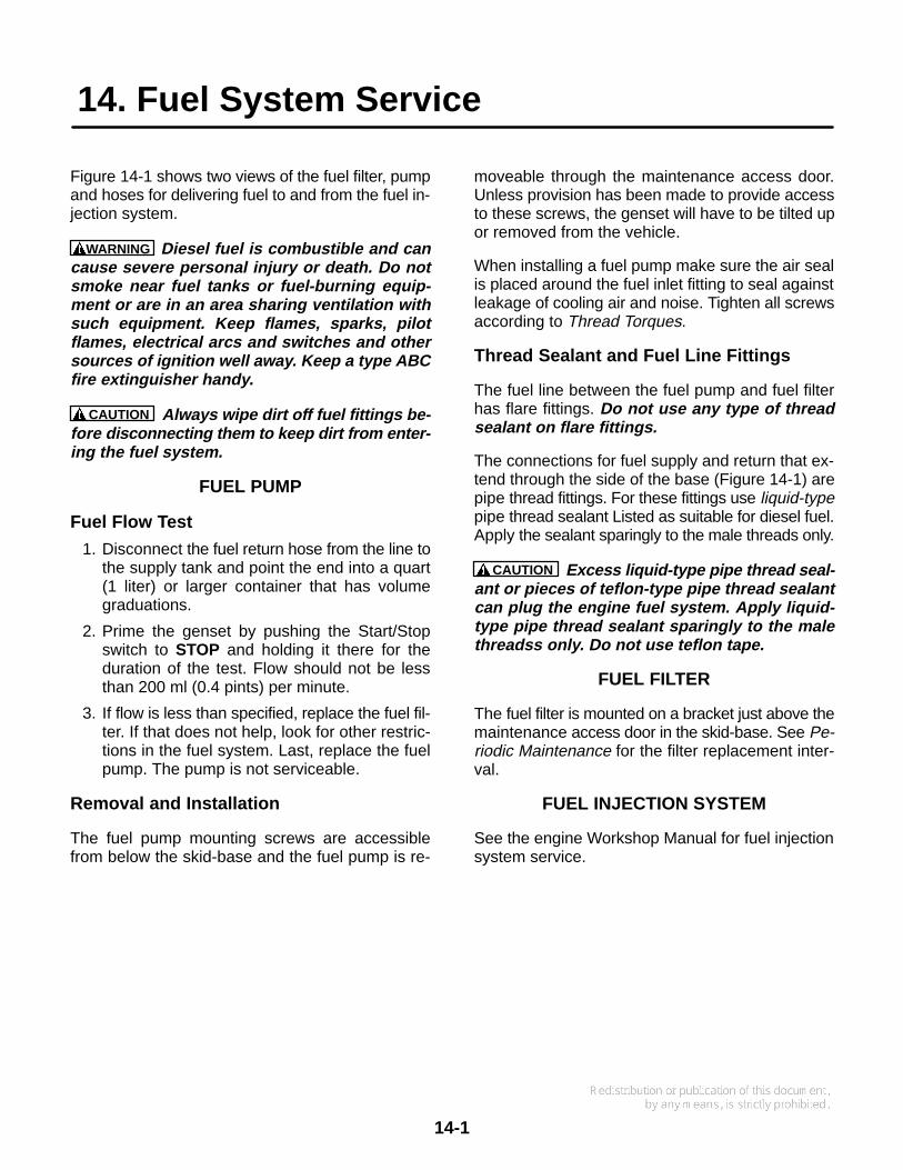
14. Fuel System Service
14-1
Figure 14-1 shows two views of the fuel filter, pumpand hoses for delivering fuel to and from the fuel in-jection system.
WARNING Diesel fuel is combustible and cancause severe personal injury or death. Do notsmoke near fuel tanks or fuel-burning equip-ment or are in an area sharing ventilation withsuch equipment. Keep flames, sparks, pilotflames, electrical arcs and switches and othersources of ignition well away. Keep a type ABCfire extinguisher handy.
CAUTION Always wipe dirt off fuel fittings be-fore disconnecting them to keep dirt from enter-ing the fuel system.
FUEL PUMP
Fuel Flow Test
1. Disconnect the fuel return hose from the line tothe supply tank and point the end into a quart(1 liter) or larger container that has volumegraduations.
2. Prime the genset by pushing the Start/Stopswitch to STOP and holding it there for theduration of the test. Flow should not be lessthan 200 ml (0.4 pints) per minute.
3. If flow is less than specified, replace the fuel fil-ter. If that does not help, look for other restric-tions in the fuel system. Last, replace the fuelpump. The pump is not serviceable.
Removal and Installation
The fuel pump mounting screws are accessiblefrom below the skid-base and the fuel pump is re-
moveable through the maintenance access door.Unless provision has been made to provide accessto these screws, the genset will have to be tilted upor removed from the vehicle.
When installing a fuel pump make sure the air sealis placed around the fuel inlet fitting to seal againstleakage of cooling air and noise. Tighten all screwsaccording to Thread Torques.
Thread Sealant and Fuel Line Fittings
The fuel line between the fuel pump and fuel filterhas flare fittings. Do not use any type of threadsealant on flare fittings.
The connections for fuel supply and return that ex-tend through the side of the base (Figure 14-1) arepipe thread fittings. For these fittings use liquid-typepipe thread sealant Listed as suitable for diesel fuel.Apply the sealant sparingly to the male threads only.
CAUTION Excess liquid-type pipe thread seal-ant or pieces of teflon-type pipe thread sealantcan plug the engine fuel system. Apply liquid-type pipe thread sealant sparingly to the malethreadss only. Do not use teflon tape.
FUEL FILTER
The fuel filter is mounted on a bracket just above themaintenance access door in the skid-base. See Pe-riodic Maintenance for the filter replacement inter-val.
FUEL INJECTION SYSTEM
See the engine Workshop Manual for fuel injectionsystem service.

14-2
FUELFILTER
FUEL RETURNFITTING
INJECTORRETURN
LINE
FUEL PUMPSHIELD
FUEL PUMP
AIR SEAL
PUMPMOUNTINGSCREWS
FUEL FILTERBRACKET
MOUNTINGSCREWS
INJECTORPUMP
SUPPLY
PUMP TOFILTER LINE
FUEL SUPPLYFITTING
FIGURE 14-1. FUEL DELIVERY SYSTEM

15. Battery Charger Service
15-1
The battery charger is optional. The charger and itstransformer are mounted on the skid-base asshown in Figure 15-1.
REMOVAL AND INSTALLATION
To remove the battery charger:
1. Disconnect the negative (-) battery cable fromthe battery to prevent the genset from startingand remove the front housing panel (p. 6-4).
2. Disconnect the quick-connectors in the twoleads to the transformer and disconnect thethird lead at the starter solenoid.
3. Remove the mounting screw.
To remove the transformer:
1. Disconnect the negative (-) battery cable fromthe battery to prevent the genset from startingand remove the front, top and left end housingpanels (p. 6-4).
2. Remove the battery charger.
3. Remove the controller/inverter assembly(p. 10-2), the cooling blower (p. 11-2) and theair intake hoses from the back of the air filterhousing (p. 7-1).
4. Disconnect the quick connectors in the two re-maining leads (four leads altogether).
5. Remove the two mounting screws.
Installation of the battery charger and transformer isthe reverse of removal. Tighten all screws accord-ing to Thread Torques.
TRANSFORMER
BATTERY CHARGER
FIGURE 15-1. BATTERY CHARGER AND TRANSFORMER

15-2

16. Starter Motor Service
16-1
REMOVAL AND INSTALLATION
See Figure 16-1. To remove the starter motor as-sembly from the genset:
1. Disconnect the negative (-) battery cable fromthe battery to prevent the genset from starting.
2. If the genset is installed in the vehicle and doesnot have an access door in the front panel,open the maintenance access door in the skid-base and remove the fuel filter and its mountingbracket (p. 14-1).
WARNING Diesel fuel is combustible andcan cause severe personal injury or death.Do not smoke. Keep flames, sparks, pilotlights, electrical arcs and arc-producingequipment and all other sources of ignitionwell away. Keep a type ABC fire extinguish-er handy.
If the genset has been removed from the ve-hicle, remove the front housing panel (p. 6-4).(If the genset has an access door in the frontpanel, remove the access door instead.)
3. Disconnect all wires and cables from the motorterminals.
4. Remove the two starter mounting bolts and re-move the starter.
Installation is the reverse of removal. Tighten boltsand terminals according to Thread Torques. FIGURE 16-1. STARTER MOTOR AND SOLENOID

16-2
STARTER SOLENOID REPLACEMENT
WARNING This test involves high electricalcurrents, strong arcing and moving parts thatcan cause severe personal injury. Do not con-duct this test near fuel tanks or when flammablevapors are present. Wear safety glasses. Keepfingers away from the pinion gear.
The starter solenoid is separately replaceable. Todetermine whether the problem is in the solenoid orin the motor:
1. Secure the motor assembly in a vice after it hasbeen removed from the genset.
2. Using a heavy jumper cable, because of thelarge currents involved, connect the motor ter-minal on the solenoid (the one closest to the
motor) to the positive (+) terminal on a 12 voltbattery.
3. Using a heavy cable from the negative (–) ter-minal on the battery, briefly touch the mountingflange on the motor.
• If the motor does not spin up quickly andsmoothly, replace the motor/solenoid as-sembly.
• If the motor does spin up quickly andsmoothly, the motor is probably okay: re-place the solenoid.The solenoid is removeable by discon-necting the motor lead from the solenoidterminal and removing the two solenoidmounting nuts. When installing a new so-lenoid, make sure the solenoid plungerengages the shift fork.

17. Service Checklist
17-1
After servicing, inspect and test the installation toconfirm that the genset will operate as intended.Check each of the areas described below beforeputting the genset into service.
Housing
Check to see that all housing panels and accesscovers are in place and secure (p. 6-4).
Mounting
Examine all mounting bolts and supporting mem-bers to verify that the genset is properly mounted.All fasteners should be tightened securely to pre-vent them from working loose when subjected tovibration.
Lubrication
If the engine oil was drained, refill as instructed inPeriodic Maintenance.
Cooling System
If the engine coolant was drained, refill as instructedin Periodic Maintenance.
Wiring
Verify that all wiring connections are tight andinstalled properly. Check each of these connec-tions:
• Load wires
• Control wires
• Ground straps
• Battery cables
Output Check
Apply a full load to make sure the genset can pro-duce its full rated output. Use a load test panel to ap-ply a progressively greater load until full load isreached.
Exhaust System
While the genset is running inspect the entire ex-haust system. Look and listen for leaks at all con-nections, welds, gaskets and joints. Also make surethe exhaust pipe is not overheating adjacent materi-als or equipment. Do not run the genset until all ex-haust leaks have been repaired.
WARNING Exhaust gas is deadly. The exhaustsystem must not leak and must discharge all ex-haust away from the vehicle. Do not run the gen-set until the exhaust leaks have been repaired.
The exhaust tailpipe must be supported by ahanger near the vehicle perimeter and terminateat least 1 inch outside the perimeter and at least1 foot from doors and windows.
Fuel System
While the genset is running, inspect the fuel supplyand return lines, filter and fittings for leaks. Checkflexible sections for cuts, cracks and abrasions andmake sure they are not rubbing against anythingthat could cause leakage. Repair all fuel leaks im-mediately.
WARNING Diesel fuel is combustible. Leakingfuel could lead to fire and to severe personal in-jury or death. Repair fuel leaks immediately.
Control
Stop and start the genset several times at the con-trol panel on the genset and at the remote controlboard (if provided) to verify that they work properly.
Mechanical
Stop the genset and inspect it for leaking gaskets,loose fasteners, damaged components and inter-ference with other equipment. Repair as necessary.Inspect the generator compartment and verify thatthere are no breaks or openings in the vapor-proofwall that separates the compartment from the ve-hicle interior. Seal openings as necessary. Makesure that all soundproofing material is in place.

17-2

18-1
18. Troubleshooting
TABLE 18-1 tabulates the Fault Codes in numericalorder along with step-by-step instructions for cor-rective action. (Fault Code numbers skipped havenot been assigned to these gensets.) First note thefollowing:
• Most shutdowns can be prevented by propermaintenance and use of the genset—main-taining oil and coolant levels, keeping batteryconnections clean and tight, watching the fuelgauge, and not overloading the genset.
• When the genset and vehicle engine share acommon fuel tank the fuel dip tubes are usu-ally arranged so that the genset will run out offuel first. Marking the genset empty point onthe fuel gauge will make it easier to tell whento stop the genset before running it out of fuel.
• The controller remains powered for 5 minutesafter genset shutdown, during which time cer-tain parameters are reset. Therefore, to re-store transient performance following a shut-down due to a high transient or load, wait atleast 5 minutes before disconnecting the bat-tery or restarting the genset.
FAULT CODESThe genset controller provides extensive diagnos-tics by causing the status indicator light on the Con-trol Switch to blink in a coded fashion. Following afault shutdown, the indicator light will blink repeat-edly: 1, 2 or 3 blinks at a time.
• One blink is code for shut down due to hightemperature
• Two blinks is code for shutdown due to a lossof engine oil pressure
• Three blinks is code for shutdown due tosome other abnormal condition.
For a 1-blink or 3-blink fault code, one touch to Stopbrings up a second-level fault code. This code con-sists of 1, 2, 3 or 4 or blinks, a brief pause, and then1 to 9 blinks. The first set of blinks represents thetens digit and the second set of blinks the units digitof the fault code number in Table 18-1. For example,Fault Code No. 23 would be:
blink-blink—pause—blink-blink-blink—...
NOTE: Consciously avoid mistaking Fault Codes 11,22 and 33 for Fault Codes 1, 2 and 3. The pauses be-
tween repetitions of the fault code are longer thanthe pauses between the tens and units digits of thethe code. For example, Fault Code 33 would be:
blink-blink-blink— pause —blink-blink-blink—longer pause —
blink-blink-blink— pause —blink-blink-blink—...
The fault code stops blinking after five minutes.Prior to Spec F , one touch to Stop restores faultcode blinking. Beginning Spec F , 3 touches to Stopare required (also earlier Spec gensets with newerreplacement controller-inverter assemblies).
NOTE: The fault displayed will be the last faultlogged, even though the condition has been cor-rected and the genset is running normally.
BYPASSABLE FAULTS(PRIOR TO SPEC F)
When a fault condition persists, the genset shutsdown when an attempt is made to restart. Prior toSpec F, (unless the controller assembly has beenreplaced) there are four faults the genset controllerwill bypass on a second attempt at restart:
• No. 17—fuel pump fault
• No. 18—glow plug fault
• No. 23—oil pressure switch fault
• No. 24—temperature sender fault.
Before making the second attempt at starting thegenset, however, consider the following:
• As long as the ambient temperature is greaterthan 77° F (25° C), a glow plug fault (No. 18)will not affect starting or operation. As the am-bient temperature keeps dropping, however,the genset will eventually fail to start.
• Bypassing an oil pressure switch fault(No. 23) or temperature sender fault (No. 24)could lead to serious engine damage if the oilpressure fails or the engine overheats.
CAUTION Operating the genset under oilpressure switch or temperature senderfault conditions can lead to serious enginedamage. Read the Warranty regarding pos-sible exclusions when operating the gensetunder such conditions.

18-2
TABLE 18-1. TROUBLESHOOTING
Some genset service procedures present hazards that can result in severe per-sonal injury or death. Only qualified service personnel with knowledge of fuels, electricity, andmachinery hazards should perform genset service. See Safety Precautions.
WARNING
GENSET WON’T STOP RUNNING—STATUS INDICATOR LIGHT ON(Faulty Stop Switch or grounded wiring)
Removing genset panels or disconnecting fuel lines to stop a genset that won’t stopcan lead to severe personal injury or death from electrocution, contact with moving parts or fire.
• Try the genset Stop Switch if the remote Stop Switch does not work and vice versa.
• If possible, pinch flexible fuel hoses until the genset stops.
• Otherwise, let the genset run out of fuel before attempting to service it.
Corrective Action:1. Try the genset Stop Switch if the remote Stop Switch does not work, and vice versa. If only the genset
Stop Switch works, go to Step 2. If neither switch works, or only the remote Stop Switch, go to Step 3.2. Disconnect the remote control panel connector (J8/P8). While pressing the Remote Stop Switch,
check for electrical continuity between remote control connector pins J8-A and J8-E. Replace aswitch that does not close when pressed to Stop and repair or reconnect wiring as necessary.
3. Remove the front and top housing panels (p. 6-4) and disconnect engine harness connector P2 fromthe controller (p. 19-1, 19-4, 10-2). Reconnect the remote control panel (J8/P8) and while pressingthe respective Stop Switch, check for electrical continuity between:
A. Pin P2-3 (remote stop) and pin P2-2 (remote ground).B. Pin P2-10 (local stop) and pin P2-11 (local ground).C. Replace a switch that does not close when pressed to Stop, check for missing, bent or corroded
terminals and connector pins and repair or reconnect wiring as necessary.4. Replace the controller assembly (p. 10-2).
WARNING
GENSET WON’T STOP RUNNING—STATUS INDICATOR LIGHT OFF(Binding governor mechanism, misadjusted speed stop)
Removing genset panels or disconnecting fuel lines to stop a genset that won’t stopcan lead to severe personal injury or death from electrocution, contact with moving parts or fire.
• Wait 5 minutes. If the governor is stuck but the fuel pump is off, it may run out of fuel.
• If possible, pinch flexible fuel hoses until the genset stops.
• Otherwise, let the genset run out of fuel before attempting to service it.
Corrective Action:1. Remove the front and top housing panels (p. 6-4) and check the fuel rack return spring and replace
it if worn or broken (p. 13-2). Make sure it is reassembled correctly.2. Check for binding in the governor mechanism by pushing the actuator rotor clockwise by hand—
against the action of the fuel rack return spring. It should rotate smoothly about 1/2 inch (12 mm) andreturn smoothly. If it binds or catches, remove the governor actuator base assembly and replace itor service the internal engine governor mechanism (p. 13-3) as necessary.
3. Readjust the actuator speed control lever stop so that the fuel rack can go to no-fuel (p. 13-5).
WARNING

18-3
TABLE 18-1. TROUBLESHOOTING (CONT.)
Some genset service procedures present hazards that can result in severe per-sonal injury or death. Only qualified service personnel with knowledge of fuels, electricity, andmachinery hazards should perform genset service. See Safety Precautions.
WARNING
STATUS INDICATOR LIGHT STAYS ON(Reversed battery connections)
Corrective Action: Reconnect the battery correctly.
ENGINE CRANKS WHEN BATTERY CONNECTED(Faulty Start Switch or grounded wiring)
Corrective Action:1. Disconnect the remote control panel connector (J8/P8). Check for electrical continuity between re-
mote control connector pins J8-A and J8-C. Replace a switch that does not open when released andrepair or reconnect wiring as necessary.
2. Remove the front and top housing panels (p. 6-4) and disconnect engine harness connector P2 fromthe controller (p. 19-1, 19-4, 10-2). Reconnect the remote control panel (J8/P8) and check for electri-cal continuity between:
A. Pin P2-1 (remote start) and pin P2-2 (remote ground).B. Pin P2-12 (local start) and pin P2-11 (local ground).C. Replace a switch that does not open when released and repair or reconnect wiring as necessary.
3. Replace the controller assembly (p. 10-2).
ENGINE WON’T CRANK—FUEL PUMP WON’T STOP(Faulty Stop Switch or grounded wiring)
Corrective Action:1. Disconnect the remote control panel connector. Check for electrical continuity between remote con-
trol connector pins J8-A and J8-E. Replace a switch that does not open when released and repairor reconnect wiring as necessary.
2. Remove the front and top housing panels (p. 6-4) and disconnect engine harness connector P2 fromthe controller (p. 19-1, 19-4, 10-2). Reconnect the remote control panel (J8/P8) and check for electri-cal continuity between:
A. Pin P2-3 (remote stop) and pin P2-2 (remote ground).B. Pin P2-10 (local stop) and pin P2-11 (local ground).C. Replace a switch that does not open when released and repair or reconnect wiring as necessary.
3. Replace the controller assembly (p. 10-2).

18-4
TABLE 18-1. TROUBLESHOOTING (CONT.)
Some genset service procedures present hazards that can result in severe per-sonal injury or death. Only qualified service personnel with knowledge of fuels, electricity, andmachinery hazards should perform genset service. See Safety Precautions.
WARNING
STATUS INDICATOR LIGHT DEAD(Faulty connections, no battery voltage)
Corrective Action:1. Try the genset Start Switch if the remote Start Switch does not work, and vice versa. Disconnect the
remote control panel (J8/P8) and try the genset Start Switch again. If nothing works, go to Step 2.If only the genset start switch works, go to Step 9. If only the remote start switch works, go to Step 12.
2. Replace Fuse F1 (B+) if blown.3. Clean and tighten the positive (+) and negative (–) battery cable connections at the battery, vehicle
frame and genset.4. Recharge or replace the battery. Refer to the battery manufacturer’s recommendations.5. Remove the front and top housing panels (p. 6-4). Check that all engine and battery harness wires
(p. 19-1, 19-3) are properly connected to the grounding bolt on the flywheel housing, to the B+ termi-nal on the starter solenoid and to the battery terminal block (p. 19-3). Clean and tighten connectionsand replace wiring as necessary.
6. Disconnect engine harness connector P1 from the controller (p. 19-1, 19-4, 10-2). Check for B+(12 VDC) at pin P1-8 and for continuity to ground at pin P1-7. Check for missing, bent or corrodedconnector pins and faulty wiring and repair as necessary.
7. Disconnect engine harness connector P2 from the controller (p. 19-1, 19-4, 10-2) and reconnect theremote control panel (J8/P8). Press the switch and check for electrical continuity between:
A. Pin P2-1 (remote start) and pin P2-2 (remote ground).B. Pin P2-3 (remote stop) and pin P2-2 (remote ground).C. Pin P2-12 (local start) and pin P2-11 (local ground).D. Pin P2-10 (local stop) and pin P2-11 (local ground).E. Replace switches that do not close when pressed, check for missing, bent or corroded terminals
and connector pins and faulty wiring and repair as necessary.8. Replace the controller assembly (p. 10-2).9. Disconnect the remote control panel (J8/P8). Check for electrical continuity between remote control
connector pins J8-A and J8-C. Replace a switch that does not close when pressed and repair or re-connect wiring as necessary.
10. Remove the front and top housing panels (p. 6-4) and disconnect engine harness connector P2 fromthe controller (p. 19-1, 19-4, 10-2) and reconnect the remote control panel (J8/P8). Press the switch,check and for electrical continuity between:
A. Pin P2-1 (remote start) and pin P2-2 (remote ground).B. Pin P2-3 (remote stop) and pin P2-2 (remote ground).C. Replace a switch that does not close when pressed, check for missing, bent or corroded termi-
nals and connector pins and faulty wiring and repair as necessary.11. Replace the controller assembly (p. 10-2).12. Remove the front and top housing panels (p. 6-4) and disconnect engine harness connector P2 from
the controller (p. 19-1, 19-4, 10-2). Press the switch and check for electrical continuity between:A. Pin P2-12 (local start) and pin P2-11 (local ground).B. Pin P2-10 (local stop) and pin P2-11 (local ground).C. Replace a switch that does not close when pressed, check for missing, bent or corroded termi-
nals and connector pins and faulty wiring and repair as necessary.13. Replace the controller assembly (p. 10-2).

18-5
TABLE 18-1. TROUBLESHOOTING (CONT.)
Some genset service procedures present hazards that can result in severe per-sonal injury or death. Only qualified service personnel with knowledge of fuels, electricity, andmachinery hazards should perform genset service. See Safety Precautions.
WARNING
STARTING BATTERIES RUN DOWN(Marginal battery[ies], connections, or charging system or parasitic loads)
Corrective Action:1. Clean and tighten the positive (+) and negative (–) battery cable connections at the battery, vehicle
frame and genset.2. Recharge or replace the battery. Refer to the battery manufacturer’s recommendations.3. Install or service a battery charging system in the vehicle if the genset is not so equipped.4. If the genset is equipped with a battery charging system, check performance by measuring voltage
across the battery terminals while running the genset. Watch the meter while turning the genset cir-cuit breaker (operator’s console) on and off several times. The battery charger is probably okay ifvoltage jumps to more than 12 VDC each time the breaker is turned on. Check for parasitic loadsexternal to the genset and/or replace the battery.
5. If the battery charger does not seem to be working, remove the front housing panel (p. 6-4). If loose,reconnect battery charger transformer input connectors J12 and J13 to the AC harness (p. 19-2,19-4), output connectors J14 and J15 to the battery charger (p. 19-4) and the battery charger outputlead to the B+ terminal on the starter solenoid.
6. Disconnect transformer connectors J12 through J15 and check winding continuity across J12–J13and across J14–J15. Replace the transformer if a winding is open (p. 15-1).
7. Reconnect J12 and J13 and run the genset. Replace the battery charger if transformer output acrossJ14–J15 is approximately 16.3 VAC. If not, go to Step 8.
8. Disconnect J12 and J13 and measure voltage. Replace the transformer if there is approximately 120VAC across J12–J13. If not, go to Step 9.
9. Replace or repair wiring in the AC harness if there is no voltage.
This test involves operating the genset with housing panels removed. The panelsguard against rotating parts and bare live electrical parts that can cause severe personal injuryor death. Keep your hands away from the engine pulleys, blower blades and electrical terminalblock TB3 on the controller housing (p. 10-2).
WARNING
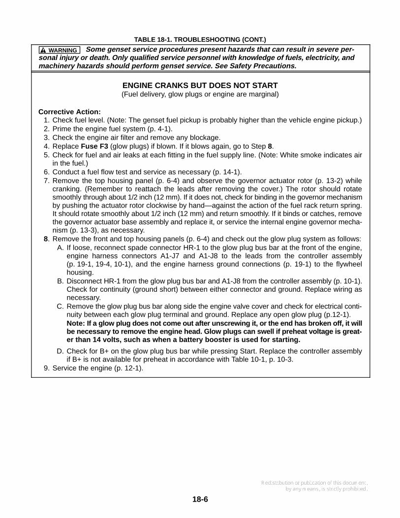
18-6
TABLE 18-1. TROUBLESHOOTING (CONT.)
Some genset service procedures present hazards that can result in severe per-sonal injury or death. Only qualified service personnel with knowledge of fuels, electricity, andmachinery hazards should perform genset service. See Safety Precautions.
WARNING
ENGINE CRANKS BUT DOES NOT START(Fuel delivery, glow plugs or engine are marginal)
Corrective Action:1. Check fuel level. (Note: The genset fuel pickup is probably higher than the vehicle engine pickup.)2. Prime the engine fuel system (p. 4-1).3. Check the engine air filter and remove any blockage.4. Replace Fuse F3 (glow plugs) if blown. If it blows again, go to Step 8.5. Check for fuel and air leaks at each fitting in the fuel supply line. (Note: White smoke indicates air
in the fuel.)6. Conduct a fuel flow test and service as necessary (p. 14-1).7. Remove the top housing panel (p. 6-4) and observe the governor actuator rotor (p. 13-2) while
cranking. (Remember to reattach the leads after removing the cover.) The rotor should rotatesmoothly through about 1/2 inch (12 mm). If it does not, check for binding in the governor mechanismby pushing the actuator rotor clockwise by hand—against the action of the fuel rack return spring.It should rotate smoothly about 1/2 inch (12 mm) and return smoothly. If it binds or catches, removethe governor actuator base assembly and replace it, or service the internal engine governor mecha-nism (p. 13-3), as necessary.
8. Remove the front and top housing panels (p. 6-4) and check out the glow plug system as follows:A. If loose, reconnect spade connector HR-1 to the glow plug bus bar at the front of the engine,
engine harness connectors A1-J7 and A1-J8 to the leads from the controller assembly(p. 19-1, 19-4, 10-1), and the engine harness ground connections (p. 19-1) to the flywheelhousing.
B. Disconnect HR-1 from the glow plug bus bar and A1-J8 from the controller assembly (p. 10-1).Check for continuity (ground short) between either connector and ground. Replace wiring asnecessary.
C. Remove the glow plug bus bar along side the engine valve cover and check for electrical conti-nuity between each glow plug terminal and ground. Replace any open glow plug (p.12-1).Note: If a glow plug does not come out after unscrewing it, or the end has broken off, it willbe necessary to remove the engine head. Glow plugs can swell if preheat voltage is great-er than 14 volts, such as when a battery booster is used for starting.
D. Check for B+ on the glow plug bus bar while pressing Start. Replace the controller assemblyif B+ is not available for preheat in accordance with Table 10-1, p. 10-3.
9. Service the engine (p. 12-1).

18-7
TABLE 18-1. TROUBLESHOOTING (CONT.)
Some genset service procedures present hazards that can result in severe per-sonal injury or death. Only qualified service personnel with knowledge of fuels, electricity, andmachinery hazards should perform genset service. See Safety Precautions.
WARNING
STARTER ENGAGES-DISENGAGES(Cranking voltage dips below 6 volts—low battery charge, poor connections, long cables)
Corrective Action:1. Have the vehicle propulsion engine running while trying to start the genset—the battery charging
alternator may be able to maintain starting voltage high enough to get the genset started.2. Clean and tighten the positive (+) and negative (–) battery cable connections at the battery, vehicle
frame and genset.3. Recharge or replace the battery. Refer to the battery manufacturer’s recommendations.4. Increase battery cable size or run parallel cables.5. Remove the front and top housing panels (p. 6-4) Check that all engine and battery harness wires
(p. 19-1, 19-3) are properly connected to the grounding bolt on the flywheel housing, to the B+ termi-nal on the starter solenoid and to the battery terminal block (p. 19-3). Clean and tighten connectionsand replace wiring as necessary.
6. Disconnect engine harness connector P1 from the controller (p. 19-1, 19-4, 10-2). Check for B+(12 VDC) at pin P1-8 and for continuity to ground at pin P1-7. Check for missing, bent or corrodedconnector pins and faulty wiring and repair as necessary.
NO POWER—GENSET RUNNING, RUN LIGHT ON(Line circuit breaker OFF or tripped or faulty wiring)
Corrective Action:1. Reset or turn “On” the line circuit breaker on the genset operator’s console.2. Reset or turn “On” the line circuit breakers on the main distribution panel in the vehicle.3. Check the voltage at genset AC output terminal block TB2. If there is approximately 120 VAC across
TB2-1 and TB2-3 and across TB2-2 and TB2-4, repair or reconnect the wiring between the gensetand the vehicle. If there is no voltage, go to Step 4.
4. Remove the front and top housing panels (p. 6-4) and check for proper AC harness connections atTB3 (p. 10-1, 19-2, 19-4), at TB2 and at the line circuit breakers (p. 19-2). Reconnect wiring as nec-essary and tighten all terminal screws and nuts.
5. Check for electrical continuity across the terminals of each breaker (p. 19-2). Replace a circuit break-er which lacks electrical continuity when “On”.
6. Run the genset and measure voltages. If there is approximately 120 VAC across TB3-1 and TB3-2,replace the AC wiring harness. If there is no voltage, replace the controller assembly (p. 10-1).
This test involves operating the genset with housing panels removed. The pan-els guard against rotating parts and bare live electrical parts that can cause severe personalinjury or death. Keep your hands, clothing, jewelry, and hair away from the engine pulleys,blower blades and electrical terminal block TB3 on the controller housing (Page 10-2).
WARNING

18-8
TABLE 18-1. TROUBLESHOOTING (CONT.)
Some genset service procedures present hazards that can result in severe per-sonal injury or death. Only qualified service personnel with knowledge of fuels, electricity, andmachinery hazards should perform genset service. See Safety Precautions.
WARNING
GENSET HUNTS UNDER FULL LOAD(Fuel delivery marginal, governor misadjusted)
Corrective Action:1. Prime the engine fuel system by holding the control switch down in its Stop position for at least 1 min-
ute.2. Check for fuel and air leaks at each fitting in the fuel supply line.3. Conduct a fuel flow test and service as necessary (p. 14-1).4. Connect a source of known fuel quality, prime the fuel system, and run the genset. If performance
improves, replace the bad fuel in the supply tank.5. Readjust high-idle speed (p. 13-6).
HIGH TEMPERATURE—FAULT CODE NO. 1(Engine coolant or inverter heat sink temperature exceeded design limit)
Corrective Action: Check the second-level fault code by touching Stop. The second-level fault will beeither No. 33 or No. 34.
LOW OIL PRESSURE—FAULT CODE NO. 2(Low oil pressure cutoff switch did not open)
Corrective Action:1. Check engine oil level and add oil as necessary.2. Drain excess oil (above dipstick Full mark).3. Remove the top housing panel (p. 6-4). Reconnect engine harness spade connector S2 to the low
oil pressure cutout switch (p. 12-3, 19-1) if it is loose (short to ground will cause shutdown).4. Disconnect engine harness connector P2 (p. 19-1) from the controller assembly (p. 10-2) and the
pressure switch. Check both ends for electrical continuity to ground. Replace wiring as necessaryif the lead is shorted to ground.
5. Install an oil pressure gauge in place of the pressure switch and observe oil pressure after the enginehas run a few minutes (let RV models step down to low idle speed). Replace the low oil pressurecutoff switch (p. 12-3) if engine oil pressure is 14 psi (98 kPa) or greater. Service the engine (p. 12-1)if engine oil pressure is less than 14 psi (98 kPa). (Simulate normal switch operation to keep the gen-set running during the test by starting with connector S2 grounded and removing it from ground whenthe engine starts.)
This test involves operating the genset with housing panels removed. The pan-els guard against rotating parts and bare live electrical parts that can cause severe personalinjury or death. Keep your hands, clothing, jewelry, and hair away from the engine pulleys,blower blades and electrical terminal block TB3 on the controller housing (Page 10-2).
WARNING

18-9
TABLE 18-1. TROUBLESHOOTING (CONT.)
Some genset service procedures present hazards that can result in severe per-sonal injury or death. Only qualified service personnel with knowledge of fuels, electricity, andmachinery hazards should perform genset service. See Safety Precautions.
WARNING
SERVICE CHECK FAULT—CODE NO. 3(A second-level fault occurred)
Corrective Action: Check the second-level fault code by touching Stop. The second-level fault will beone of the following in this table.
OVERCURRENT FAULT—CODE NO. 11(AC output short)
Corrective Action:1. Turn off the genset line circuit breaker. If the genset no longer shuts down, the genset is probably
okay—check for and repair a short circuit in the vehicle appliances, wiring or shorted battery chargertransformer.
2. Check whether the vehicle engine and genset share the same starting battery. If so, and this faultoccurs when cranking the vehicle engine, low battery voltage may be causing this shutdown. In-crease battery capacity or install a separate battery and battery charging system for the genset. Ifthe genset still shuts down and has Option Code “11296” in the Model Number, go to Step 3. If not,go to Step 4.
3. Remove the front and top housing panels (p. 6-4) and disconnect the AC harness (Page 19-3) fromTB3 on the controller assembly (p. 10-2). Reconnect the short grounding lead in the harness toTB3-2 so that the genset will run. If the genset no longer shuts down, find and repair the short in theAC harness, reconnecting the line circuit breaker (p. 19-2), output terminal block (TB2) and batterycharger as necessary.
This test involves operating the genset with housing panels removed. The pan-els guard against rotating parts and bare live electrical parts that can cause severe personalinjury or death. Keep your hands, clothing, jewelry, and hair away from the engine pulleys,blower blades and electrical terminal block TB3 on the controller housing (Page 10-2).
4. Replace the controller assembly (p. 10-2).
WARNING
INVERTER OVERVOLTAGE FAULT—CODE NO. 12(Controller not able to regulate to rated voltage)
Corrective Action:1. Check whether the vehicle engine and genset share the same starting battery. If so, and this fault
occurs when cranking the vehicle engine, low battery voltage may be causing this shutdown. In-crease battery capacity or install a separate battery and battery charging system for the genset.
2. Replace the controller assembly (p. 10-2).

18-10
TABLE 18-1. TROUBLESHOOTING (CONT.)
Some genset service procedures present hazards that can result in severe per-sonal injury or death. Only qualified service personnel with knowledge of fuels, electricity, andmachinery hazards should perform genset service. See Safety Precautions.
WARNING
INVERTER UNDERVOLTAGE FAULT—CODE NO. 13(Controller not able to regulate to rated voltage)
Corrective Action:1. Check whether the vehicle engine and genset share the same starting battery. If so, and this fault
occurs when cranking the vehicle engine, low battery voltage may be causing this shutdown. In-crease battery capacity or install a separate battery and battery charging system for the genset.
2. Remove the front and top housing panels (p. 6-4).A. If loose, reconnect the leads of current transformer (p. 19-2, 19-4) to controller leads J9 and J10.
If that does not work, check resistance. If electrical resistance is not 15 to 25 ohms, replace thecurrent transformer.
B. Check for proper connections between the generator (PMA) and the controller assembly andreconnect as necessary (p. 10-2, 11-1, 19-4).
C. Check for a shorted generator winding (p. 11-1). If a winding is shorted, replace the generator.3. Replace the controller assembly (p. 10-2).
INVERTER OVERFREQUENCY FAULT—CODE NO. 14(Controller not able to regulate to rated frequency)
Corrective Action:1. Reduce the number of connected appliances, especially when air conditioners and battery chargers
are running.2. Replace the controller assembly (p. 10-2).
INVERTER UNDERFREQUENCY FAULT—CODE NO. 15(Controller not able to regulate to rated frequency)
Corrective Action:1. Reduce the number of connected appliances, especially when air conditioners and battery chargers
are running.2. Verify that air conditioners are working properly and not creating a low power factor loading condition
on the genset.3. Remove the top housing panel (p. 6-4) and check for and correct connections at terminal TB3-1 and
TB3-2 (p. 10-2).4. Replace the controller assembly (p. 10-2).

18-11
TABLE 18-1. TROUBLESHOOTING (CONT.)
Some genset service procedures present hazards that can result in severe per-sonal injury or death. Only qualified service personnel with knowledge of fuels, electricity, andmachinery hazards should perform genset service. See Safety Precautions.
WARNING
FUEL PUMP FAULT—CODE NO. 17*(Controller sensed open circuit)
Corrective Action:1. Try priming the fuel system by holding the control switch at Stop. If the fuel pump functions, the fault
was improperly declared and will probably not recur.2. If loose, reconnect the two fuel pump leads (p. 19-1, 19-4). They are accessible through the access
door in the skid-base, and also through an access door in the front panel on some models.3. Disconnect the fuel pump leads from the engine wiring harness and connect the white fuel pump lead
to the positive (+) terminal of a 12 volt battery and the black lead to the negative (–) terminal. Replacethe pump if there is no audible sound or vibration.
4. Remove the front and top housing panels (p. 6-4) and disconnect engine harness connector P1(p. 19-1, 19-4) from the controller assembly (p. 10-2). Check for electrical continuity between pinP1-2 and connector E2-1 and between E2-2 and ground and repair as necessary. Also check formissing, bent or corroded terminals and connector pins and repair or reconnect as necessary.
* – This is a bypassable fault (p. 18-1), discontinued beginning Spec F.
GLOW PLUG CIRCUIT PROTECTION FAULT—CODE NO. 18*(Controller sensed short circuit)
Corrective Action: 1. Remove the top housing panel (p. 6-4) and, if loose, reconnect engine harness spade connector
HR-1 (p. 19-1, 19-4) to the glow plug bus bar at the front of the engine (short to ground will causeshutdown).
2. Disconnect engine harness connector HR-1 at the glow plug bus bar and A1-J8 at the controller as-sembly (p. 10-2). Check for continuity between either connector and ground (ground short). Replacethe engine harness if it is shorted to ground.
3. Replace the controller assembly (p. 10-2).* – This is a bypassable fault (p. 18-1), discontinued beginning Spec F.
GOVERNOR ACTUATOR FAULT—CODE NO. 19(Controller sensed open or short circuit)
Corrective Action:1. Remove the front housing panel (p. 6-4) and reconnect the engine wiring harness connectors E1-1
and E1-2 to the governor actuator if they are loose. Polarity does not matter (p. 19-1, 13-1).2. Measure actuator coil resistance with a digital ohmmeter. Replace the actuator stator assembly if
coil resistance is not 1.7 to 2.8 ohms.3. Disconnect engine harness connector P1 from the controller assembly (p. 19-1, 19-4). Check for
electrical continuity between pin P1-1 and quick connector E1-1 and between E1-2 and ground. Re-place the engine harness if either leg lacks electrical continuity. Also check for missing, bent or cor-roded terminals and connector pins and repair or reconnect as necessary.

18-12
TABLE 18-1. TROUBLESHOOTING (CONT.)
Some genset service procedures present hazards that can result in severe per-sonal injury or death. Only qualified service personnel with knowledge of fuels, electricity, andmachinery hazards should perform genset service. See Safety Precautions.
WARNING
STARTER SOLENOID CIRCUIT PROTECTION FAULT—CODE NO. 21*(Controller sensed short circuit)
Corrective Action:1. Open the maintenance access door and reconnect engine harness quick connector K-1 to the starter
motor solenoid if it is loose (p.19-1, 19-4).2. Disconnect engine harness connector K-1 from the starter solenoid and connect battery positive (+)
by means of a switch and jumper to energize the solenoid. If the starter does not crank the enginewhen the solenoid is energized, remove the starter motor assembly. Replace the starter motor as-sembly or solenoid, as necessary (p. 16-1).
3. Remove the top housing panel (p. 6-4) and reconnect engine harness connector A1-J6 to the leadfrom the controller/inverter assembly if it is loose (p. 10-2).
4. Disconnect engine harness connector A1-J6 at the controller/inverter assembly and connector K1at the starter solenoid and check for continuity to ground from either connector (ground short). Re-place the engine harness if it is shorted to ground.
5. Replace the controller assembly (p. 10-2).* – Discontinued beginning Spec F.
GOVERNOR ACTUATOR OVERLOAD FAULT—CODE NO. 22(Duration of operation at or near full-duty cycle beyond design limit)
Corrective Action:1. Reduce the number of connected appliances, especially when air conditioners and battery chargers
are running.2. Check for fuel and air leaks at each fitting in the fuel supply line.3. Conduct a fuel flow test and service as necessary (p. 14-1).4. Replace the engine air filter (p. 5-6) and clean the spark-arrest muffler (p. 5-5).5. Remove the front and top housing panels (p. 6-4). Check for binding in the governor mechanism by
pushing the actuator rotor clockwise by hand—against the action of the fuel rack return spring. Itshould rotate smoothly about 1/2 inch (12 mm) and return smoothly. If it binds or catches, removethe governor actuator base assembly and replace it or service the internal engine governor mecha-nism (p. 13-3) as necessary.
6. Readjust high-idle speed (p. 13-6).7. Service the fuel injectors and injection pump as necessary (p. 12-1).8. Check fuel injection timing (p. 12-1).9. Service a worn engine (p. 12-1).

18-13
TABLE 18-1. TROUBLESHOOTING (CONT.)
Some genset service procedures present hazards that can result in severe per-sonal injury or death. Only qualified service personnel with knowledge of fuels, electricity, andmachinery hazards should perform genset service. See Safety Precautions.
WARNING
LOW OIL PRESSURE CUTOFF SWITCH FAULT—CODE NO. 23*(Controller sensed switch still open during start—not a running fault**)
Corrective Action:1. Remove the top housing panel (p. 6-4). If loose, reconnect engine harness spade connector S2 to
the low oil pressure cutoff switch (p. 12-3, 19-1).2. Disconnect engine harness connector P2 from the controller assembly (p. 10-2). Check for electrical
continuity between pin P2-9 and connector S2 and for missing, bent or corroded connector pins andrepair as necessary.
3. Check for loose or corroded ground connections between the engine and the base (p. 19-3) and thebase and controller assembly (p. 10-2) and repair as necessary.
4. Replace the low oil pressure cutoff switch (p. 12-3).* – This is a bypassable fault (p. 18-1) prior to Spec F.
** – Beginning Spec F, this fault is enabled 20 seconds after the genset stops and is declared during start.
COOLANT TEMPERATURE SENDER FAULT—CODE NO. 24*(Controller did not sense temperature change during first 5 minutes of operation)
Corrective Action:1. Remove the top housing panel (p. 6-4). If loose, reconnect engine harness spade connector E3-1
to the coolant temperature sender (p. 12-3, 19-1).2. Disconnect engine harness connector P1 from the controller assembly (p. 10-2). Check for electrical
continuity between pin P1-12 and connector E3-1 and for missing, bent or corroded connector pinsand repair as necessary.
3. Replace the coolant temperature sender (p. 12-3).* – This is a bypassable fault (p. 18-1) prior to Spec F. Note also that an open circuit is sensed as cold temperature, resulting in maximum pre-heatand post-heat times.
ENGINE ABOVE SPEED TARGET FAULT—CODE NO. 25(Governor unable to regulate to target speed)
Corrective Action:1. Remove the front and top housing panels (p. 6-4). Check the fuel rack return spring and replace it
if it is worn or broken (p. 13-2). Make sure it is reassembled correctly.2. Check for binding in the governor mechanism by pushing the actuator rotor clockwise by hand—
against the action of the fuel rack return spring. It should rotate smoothly about 1/2 inch (12 mm) andreturn smoothly. If it binds or catches, remove the governor actuator base assembly and replace itor service the internal engine governor mechanism (p. 13-3) as necessary.
3. Readjust high-idle speed (p. 13-4).

18-14
TABLE 18-1. TROUBLESHOOTING (CONT.)
Some genset service procedures present hazards that can result in severe per-sonal injury or death. Only qualified service personnel with knowledge of fuels, electricity, andmachinery hazards should perform genset service. See Safety Precautions.
WARNING
ENGINE BELOW SPEED TARGET FAULT—CODE NO. 26(Governor unable to regulate to target speed)
Corrective Action:1. Reduce the number of connected appliances, especially when air conditioners and battery chargers
are running.2. Prime the engine fuel system (p. 4-1).3. Check for fuel and air leaks at each fitting in the fuel supply line.4. Conduct a fuel flow test and service as necessary (p. 14-1).5. Replace the engine air filter (p. 5-6) and clean the spark-arrest muffler (p. 5-5).6. Connect a source of known fuel quality, prime the fuel system (p. 4-1) and run the genset. If perfor-
mance improves, replace the bad fuel in the supply tank.7. Remove the front and top housing panels (p. 6-4). Check for binding in the governor mechanism by
pushing the actuator rotor clockwise by hand—against the action of the fuel rack return spring. Itshould rotate smoothly about 1/2 inch (12 mm) and return smoothly. If it binds or catches, removethe governor actuator base assembly and replace it or service the internal engine governor mecha-nism (p. 13-3) as necessary.
8. Readjust high-idle speed (p. 13-4).9. Service the fuel injectors and injection pump, as necessary (p. 12-1).
10. Check fuel injection timing (p. 12-1).11. Service a worn engine (p. 12-1).
PMA SENSE LOST FAULT—CODE NO. 27(Controller unable to sense PMA frequency)
Corrective Action:1. Check for proper connections between the generator (PMA) and the controller assembly and recon-
nect as necessary (p. 10-2, 11-1, 19-4).2. Check for an open generator winding (p. 11-1). If a winding is open, replace the generator.3. Replace the controller assembly (p. 10-2).
DC SENSE LOST FAULT—CODE NO. 28(Controller unable to sense DC bus voltage)
Corrective Action:1. Open the circuit breaker. If the fault does not persist, check for and disconnect excessive loads from
the genset before starting.2. Check for proper connections between the generator (PMA) and the controller assembly and recon-
nect as necessary (p. 10-2, 11-1, 19-4).3. Replace the controller assembly (p. 10-2).

18-15
TABLE 18-1. TROUBLESHOOTING (CONT.)
Some genset service procedures present hazards that can result in severe per-sonal injury or death. Only qualified service personnel with knowledge of fuels, electricity, andmachinery hazards should perform genset service. See Safety Precautions.
WARNING
HIGH BATTERY VOLTAGE FAULT—CODE NO. 29(Voltage across battery system greater than 17.5 volts)
Corrective Action:1. Check battery bank connections and reconnect if necessary so that the 12 volt batteries serving the
genset are connected in parallel (12 volt) rather than in series (24 volt).2. Select a lower battery booster charge rate.
OVERSPEED FAULT—CODE NO. 31(Engine speed greater than 3600 rpm)
Corrective Action:1. Remove the front and top housing panels (p. 6-4). Check for binding in the governor mechanism by
pushing the actuator rotor clockwise by hand—against the action of the fuel rack return spring. Itshould rotate smoothly about 1/2 inch (12 mm) and return smoothly. If it binds or catches, removethe governor actuator base assembly and replace it or service the internal engine governor mecha-nism (p. 13-3) as necessary.
2. Readjust high-idle speed (p. 13-4).
LOW CRANKING SPEED FAULT—CODE NO. 32(Cranking speed less than 180 rpm for more than 2 seconds)
Corrective Action:1. Replace Fuse F2 (starter solenoid) if blown. If it blows again, open the maintenance access door
(bottom) and reconnect engine harness connector K-1 (p. 19-1, 19-4) to the starter motor solenoid.2. Clean and tighten the positive (+) and negative (–) battery cable connections at the battery and at
the genset.3. Recharge or replace the battery. Refer to the battery manufacturer’s recommendations.4. Replace the engine oil (p. 5-4) with oil of proper viscosity for the ambient temperature (p. 4-1). (High
oil viscosity can slow cranking speed.)5. Open the maintenance access door and disconnect engine harness connector K-1 from the starter
solenoid. Connect battery positive (+) by means of a switch and jumper to energize the solenoid. Ifthe starter does not crank the engine when the solenoid is energized, remove the starter motor as-sembly. Replace the starter motor assembly or solenoid, as necessary (p. 16-1).
6. Remove the top housing panel (p. 6-4). Check the PMA rotor and the integrity of the magnets. At-tempt to bar the engine by hand to check for jammed magnets. Replace the rotor if damaged(p. 11-2).
7. Disconnect engine harness connector A1-J6 at the controller assembly (p. 10-2) and connector K1at the starter solenoid and check for continuity to ground at either connector (ground short) and repairas necessary.
8. Disconnect the PMA stator leads (p. 11-1) and listen to cranking speed while trying to start. If crank-ing speed is considerably higher when the PMA is not connected, replace the controller assembly(p. 10-2) as internal components have probably shorted.

18-16
TABLE 18-1. TROUBLESHOOTING (CONT.)
Some genset service procedures present hazards that can result in severe per-sonal injury or death. Only qualified service personnel with knowledge of fuels, electricity, andmachinery hazards should perform genset service. See Safety Precautions.
WARNING
HIGH ENGINE COOLANT TEMPERATURE FAULT—CODE NO. 33(Engine coolant temperature exceeded design limit)
Corrective Action:1. Check the engine coolant level and add coolant and repair leaks as necessary (p. 9-1, 12-1).2. Check for and remove any objects blocking the air inlet or outlet openings in the bottom of the genset.3. Reduce the number of appliances connected at the same time. (Note that high altitude and high am-
bient temperature decrease engine cooling capacity.)4. Look for a broken or worn coolant pump drive belt (p. 12-3) and replace as necessary (p. 12-1). (Vis-
ible through the maintenance access door in the skid-base.)5. Remove the air intake grille in the skid-base and check to see that the cooling blower (p. 11-1) is
secure and that the blades are not fouled.6. Check for air leaks in the housing—missing or loose housing panels and access covers, including
the access covers for the fuses and AC terminals.7. Clean and flush the cooling system to remove coolant passage fouling.8. Remove the top housing panel (p. 6-4). If loose, reconnect engine harness spade terminal connector
E3-1 to the coolant temperature sender (p. 12-1, 19-1). (If the lead is loose and touching ground, thecontroller will sense a high engine temperature.)
9. While the top housing panel is off (Step 8), check for fouling of the radiator air passages and clearout dust and debris with compressed air directed from below (reverse of normal air flow).
Wear safety glasses when using compressed air to prevent severe eye injury.
10. Replace the coolant thermostat (p. 12-1).11. If the genset overheats only underway, see the coach manufacture regarding air baffles or other
means to direct cooling air into the genset.
WARNING
HIGH INVERTER TEMPERATURE FAULT—CODE NO. 34(Inverter heat sink temperature exceeded design limit*)
Corrective Action:1. Check for and remove any objects blocking the air inlet or outlet openings in the bottom of the genset.2. Remove the air intake grille in the skid-base and clean the heat sink fins (p. 10-2) if they are fouled.
Also check to see that the cooling blower (p. 11-1) is secure and that the blades are not fouled.3. Reduce the number of appliances connected at the same time. (Note that high altitude and high am-
bient temperature decrease cooling capacity.)4. Replace the controller assembly (p. 10-2) if the genset cannot carry rated load.
*– Prior to Spec F, use compressed air to cool off the fins of the heat sink (p. 10-2) if it is necessary to get the genset started right away. BeginningSpec F, the genset will run for 2 minutes after being restarted, which is enough time to cool down the heat sink if the connected load is less than2 kW.
CONTROL CARD FAILURE FAULT—CODE NO. 35(Microprocessor EEPROM error during self-test)
Corrective Action: Report this failure to the Factory and replace the controller assembly (p. 10-2).This fault occurs when using obsolete software.

18-17
TABLE 18-1. TROUBLESHOOTING (CONT.)
Some genset service procedures present hazards that can result in severe per-sonal injury or death. Only qualified service personnel with knowledge of fuels, electricity, andmachinery hazards should perform genset service. See Safety Precautions.
WARNING
ENGINE STOPPED FAULT—CODE NO. 36(Engine stopped without command by controller)
Corrective Action:1. Check fuel level. (Note: The genset fuel pickup is probably higher than the vehicle engine pickup.)2. Prime the engine fuel system if the genset ran out of fuel (p. 4-1).3. Check for fuel and air leaks at each fitting in the fuel supply line. (Note: White smoke indicates air
in the fuel.)4. Check the engine air filter and remove any blockage.5. Check for mechanical damage.6. Check auxiliary fuel pump (if equipped).7. Conduct a fuel flow test and service as necessary (p. 14-1).8. Remove the front and top housing panels (p. 6-4) and disconnect engine harness connectors P1 and
P2 from the controller (p. 19-1, 19-4, 10-2). Check for missing, bent or corroded connector pins andfaulty wiring and repair as necessary.
9. Service the engine (p. 12-1).
INVALID GENSET CONFIGURATION FAULT—CODE NO. 37(Genset configuration is preprogrammed at the factory)
Corrective Action: Replace the controller assembly (p. 10-2). The controller assembly must be config-ured at the factory.

18-18
TABLE 10-3. TROUBLESHOOTING
Some genset service procedures present hazards that can result in severe per-sonal injury or death. Only qualified service personnel with knowledge of fuels, electricity, andmachinery hazards should perform genset service. See Safety Precautions.
WARNING
OVERCURRENT FAULT—CODE NO. 38(Too many loads connected)
Corrective Action:1. Reduce the number of appliances running at the same time, especially those with high motor starting
loads such as air conditioners. Start up with no load and let the genset run for five minutes to cooldown the inverter.
2. If the appliance and air conditioner loading patterns have remained the same but genset perfor-mance has deteriorated:
A. Check for fuel and air leaks at each fitting in the fuel supply line. (Note: White smoke indicatesair in the fuel.)
B. Conduct a fuel flow test and service as necessary (p. 14-1).C. Remove the front and top housing panels (p. 6-4). Check for binding in the governor mechanism
by pushing the actuator rotor clockwise by hand—against the action of the fuel rack returnspring. It should rotate smoothly about 1/2 inch (12 mm) and return smoothly. If it binds orcatches, remove the governor actuator base assembly and replace it or service the internal en-gine governor mechanism (p. 13-3) as necessary.
D. Readjust high-idle speed (p. 13-4).E. Service the fuel injectors and injection pump as necessary (p. 12-1).F. Service a worn engine (p. 12-1).
LOW BATTERY VOLTAGE FAULT—CODE NO. 39*(Battery voltage dropped below 9 volts while genset running)
Corrective Action:1. Clean and tighten the positive (+) and negative (–) battery cable connections at the battery and at
the genset.2. Avoid running the genset while cranking the vehicle engine in installations where the genset batteries
are used to supplement the vehicle engine batteries.* – Discontinued beginning Spec F.
PROCESSOR FAULT—CODE NO. 42*(Microprocessor ROM error during self-test)
Corrective Action: Replace the controller assembly (p. 10-2).* – Beginning Spec F and for replacement controller assemblies

18-19
TABLE 10-3. TROUBLESHOOTING (CONT.)
Some genset service procedures present hazards that can result in severe per-sonal injury or death. Only qualified service personnel with knowledge of fuels, electricity, andmachinery hazards should perform genset service. See Safety Precautions.
WARNING
PROCESSOR FAULT—CODE NO. 43*((Microprocessor RAM error during self-test)
Corrective Action: Replace the controller assembly (p. 10-2).* – Beginning Spec F and for replacement controller assemblies
INVERTER POWER SUPPLY FAULT—CODE NO. 46*(Low battery voltage or power supply device failure)
Corrective Action:1. Avoid running the genset while cranking the vehicle engine in installations where the genset batteries
are used to supplement the vehicle engine batteries.2. Clean and tighten the positive (+) and negative (–) battery cable connections at the battery, vehicle
frame and genset.3. Recharge or replace the battery. Refer to the battery manufacturer’s recommendations.4. Install or service a battery charging system in the vehicle if the genset is not so equipped.5. Replace the controller assembly (p. 10-2).
* – Beginning Spec F and for replacement controller assemblies

18-20

19-1
ENGINE WIRING HARNESS
TIE TO ACHARNESS
SECURE TO TOP OF CONTROLLERHOUSING WITH SUPPORT CLIP
SECURE TO TOP OF INTAKE RES-ONATOR WITH SUPPORT CLIP
SECURE TO END OFINTAKE RESONATORWITH SUPPORT CLIP
1
EARLIER MODELS
LATER MODELS

19-2
AC WIRING HARNESS
HARNESS WHEN GENSET IS NOTEQUIPPED WITH BATTERY CHARGER
HARNESS WHEN GENSET ISEQUIPPED WITH BATTERY CHARGER
SECURE TO TOP OF CONTROLLERHOUSING WITH SUPPORT CLIP
TIE WITH ENGINEHARNESS
NOT USED
TWO LEADS WHEN GEN-SET IS EQUIPPED WITHA BATTERY CHARGER
CURRENTTRANSFORMER
2
EARLIER MODELS
LATER MODELS

19-3
BATTERY WIRING HARNESS
SECURE HARNESSSUPPORT CLIPS HERE
SECURE PCBGROUND HERE
SECURE GNDCABLE HERE
SECURE B+CABLE HERE
SECURE HARNESSSUPPORT CLIPS HERE
3
EARLIER MODELS ONLY

19-4
WIRING DIAGRAM
CONTROLLER/INVERTER ASSEMBLY
PRIOR TO SPEC F
4

Cummins Power Generation1400 73rd Avenue N.E.Minneapolis, MN 55432763-574-5000Fax: 763-528-7229
Cummins and Onan are registered trademarks of Cummins Inc.