Causal Patterns in Simple Circuits - · Causal Patterns in Simple Circuits: Lessons to Infuse ......
143
Causal Patterns in Simple Circuits: Lessons to Infuse into Electricity Units to Enable Deeper Understanding The Understandings of Consequence Project Project Zero, Harvard Graduate School of Education
Transcript of Causal Patterns in Simple Circuits - · Causal Patterns in Simple Circuits: Lessons to Infuse ......
Causal Patterns in Simple Circuits:
Lessons to Infuse into Electricity Units to Enable Deeper Understanding
The Understandings of Consequence Project Project Zero, Harvard Graduate School of Education

This module was created by Tina Grotzer and Margot Sudbury with contributions from a number of individuals. Dorothy MacGillivray, Rebecca Lincoln, and Sarah Mittlefehldt made numerous substantive improvements and worked diligently to bring the module to fruition. Eric Buchovecky offered detailed and insightful comments on the teaching and learning challenges involved. David Perkins provided insights on the nature of the causalities involved. Belinda Bell Basca, Kiki Donis, Dorothy MacGillivray, and Melanie Pincus assisted in analyzing the data that we collected on teaching the concepts in these lessons. Dorothy MacGillivray was responsible for much of the design and lay-out. Rebecca Lincoln made numerous edits to strike a balance between clarity and accuracy given the complexity of the material. Sarah Mittlefehldt worked magic editing images and diagrams. Kiki Donis and Rebekah Gould helped to develop diagrams and explanations. We are especially appreciative to our science consultants: Roger Sudbury, Electrical Engineer at MIT and Joseph Snir, Physics Education Professor at the University of Haifa, Israel, for their patience with our many questions and their good humor in finding ways to explain complex concepts in ways that students could grasp. We are immensely grateful to Nora Sabelli, Ken Whang, and Elizabeth Vanderputten at the National Science Foundation for their support and guidance. The teachers in the Burlington, Arlington, and Billerica, MA Public Schools, specifically David Thibault, Kim Piccolo, Jim Stanger, Lynda Verity, Gini MacAuley, Eric Buchovecky, and Eileen Kenneally worked with us to test the concepts with their students. We are grateful to them for their patience and insight. Thank you to John Papadonis of the Burlington Schools’ Science Center for his support and helpful suggestions. We thank the administrators, Dr. Bill Conners, Mr. Richard Connors, Dr. Joanne Gurry, Mr. Stephen Carme, Mr. Mike McCabe, Dr. Thomas Sharkey, and Mr. Joseph LoDuca. We especially thank the many students who shared their thinking with us over the past six years. ©2004, President and Fellows of Harvard College for the Understandings of Consequence Project of Project Zero, Harvard Graduate School of Education, 124 Mount Auburn Street, 5th Floor, Cambridge, MA 01238
This work was supported by the National Science Foundation, Grant No. REC-9725502 and No. REC-0106988 to Tina Grotzer and David Perkins, Co- Principal Investigators. Any opinions, findings, conclusions or recommendations expressed here are those of the authors and do not necessarily reflect the views of the National Science Foundation.
©2004, President and Fellows of Harvard College
Table of Contents
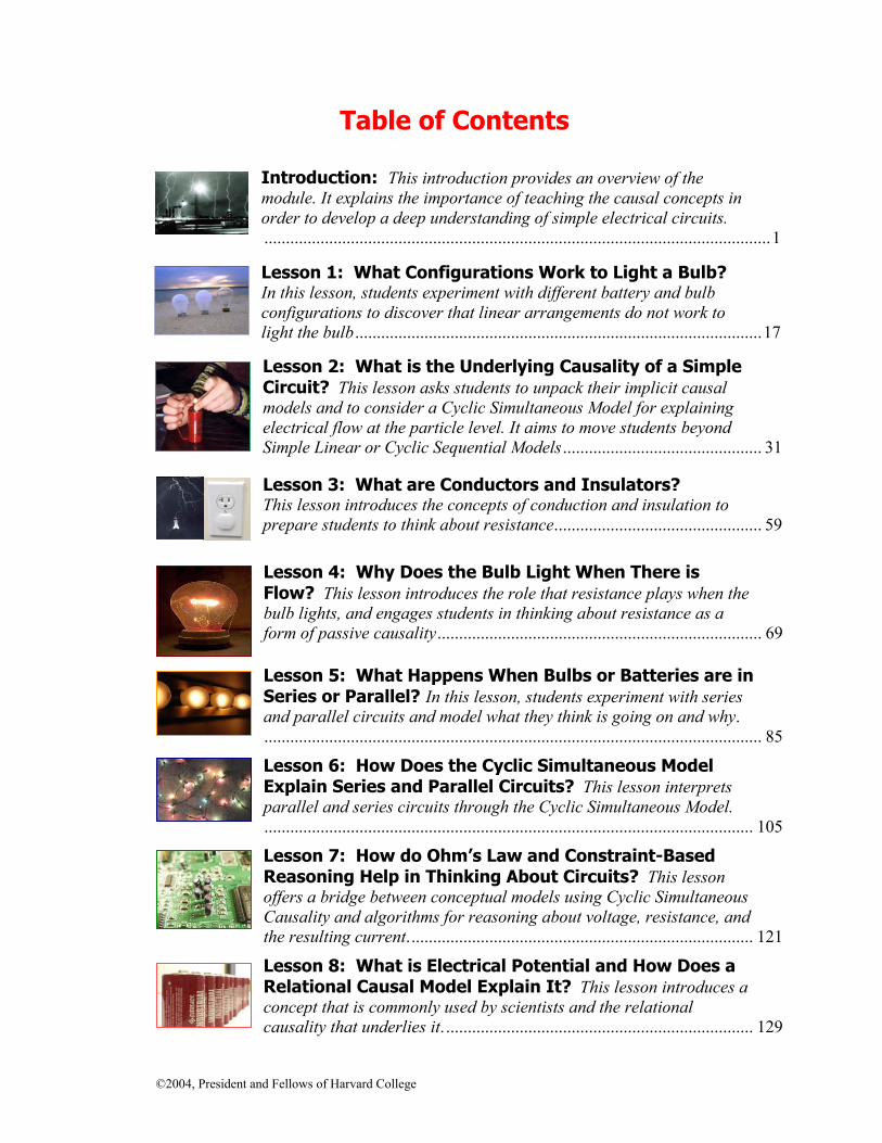
Introduction: This introduction provides an overview of the module. It explains the importance of teaching the causal concepts in order to develop a deep understanding of simple electrical circuits. .....................................................................................................................1
Lesson 1: What Configurations Work to Light a Bulb? In this lesson, students experiment with different battery and bulb configurations to discover that linear arrangements do not work to light the bulb ..............................................................................................17
Lesson 2: What is the Underlying Causality of a Simple Circuit? This lesson asks students to unpack their implicit causal models and to consider a Cyclic Simultaneous Model for explaining electrical flow at the particle level. It aims to move students beyond Simple Linear or Cyclic Sequential Models .............................................. 31
Lesson 3: What are Conductors and Insulators? This lesson introduces the concepts of conduction and insulation to prepare students to think about resistance................................................ 59
Lesson 4: Why Does the Bulb Light When There is Flow? This lesson introduces the role that resistance plays when the bulb lights, and engages students in thinking about resistance as a form of passive causality........................................................................... 69
Lesson 5: What Happens When Bulbs or Batteries are in Series or Parallel? In this lesson, students experiment with series and parallel circuits and model what they think is going on and why. ................................................................................................................... 85
Lesson 6: How Does the Cyclic Simultaneous Model Explain Series and Parallel Circuits? This lesson interprets parallel and series circuits through the Cyclic Simultaneous Model. ................................................................................................................. 105
Lesson 7: How do Ohm’s Law and Constraint-Based Reasoning Help in Thinking About Circuits? This lesson offers a bridge between conceptual models using Cyclic Simultaneous Causality and algorithms for reasoning about voltage, resistance, and the resulting current................................................................................ 121
Lesson 8: What is Electrical Potential and How Does a Relational Causal Model Explain It? This lesson introduces a concept that is commonly used by scientists and the relational causality that underlies it. ....................................................................... 129


©2004, President and Fellows of Harvard College 1
INTRODUCTION
This introduction provides an overview of the module. It explains the
importance of teaching the causal concepts presented in order to develop a deep understanding of simple electrical circuits. It suggests ways to encourage a classroom culture that supports the development of the
understanding goals of the module.

©2004, President and Fellows of Harvard College 3
Introduction
Overview This curriculum module consists of a set of lessons that are to be infused into a broader unit on simple electrical circuits. The lessons are designed to address a set of persistent misunderstandings that students have when learning about simple circuits. These misunderstandings stem from how students reason about the nature of causality. The lessons address persistent and problematic linear and sequential models that students typically use to reason about simple circuits. The module is designed to move students away from these linear and sequential models towards more complex models that better explain the way circuits work. Two models (each with an underlying causality that is different from the linear model) are introduced and used to reason about topics such as why the bulb in a simple circuit lights, series and parallel circuits, and Ohm’s Law. Background information is given to help teachers understand typical misunderstandings and how each shows up in students’ reasoning about simple circuits. Each lesson includes subject matter goals and more general goals about the nature of cause and effect. The module is designed for middle school, but can be adjusted for use with younger and older students. Teaching about static electricity is recommended before teaching about electrical circuits. Understanding electrical charge helps prepare students for understanding electrical circuits. Each lesson consists of a set of steps. Analyze Thinking is typically the first step. It asks students to reflect on their current ideas because these ideas can be resistant to change if they are not addressed. Next, students are asked to Explore Outcomes by gathering data towards future model revision, or to RECAST Thinking by completing an activity or discussion designed to REveal CAusal STructure or help students RECAST their understandings so that they fit with the causal patterns that scientists use. The Explore Causality step engages students in explicit conversation about the nature of the causality involved in the specific phenomenon under consideration. Finally, the Review, Extend, Apply step asks students to assess their understanding and to connect the knowledge beyond the original learning context. The steps are used in lessons as needed. Not all lessons have all steps. The curriculum is designed around best practices in science education. Lessons involve students in inquiry-based activities that ask them to observe and construct understandings. Lessons typically begin by getting students to examine their current beliefs and accommodate the fact that students’ ideas will evolve during the course of the unit. Student discussion is a central activity, and teachers are encouraged to create an environment where students are comfortable sharing their ideas and where they realize that science involves revising ideas to come up with ones that best explain the phenomena in question.
Causal Patterns in Simple Circuits: Introduction
4 ©2004, President and Fellows of Harvard College
Challenges in Understanding the Causality of Simple Circuits Students typically have misconceptions about how simple circuits work.1 If you ask your students to draw a model to explain a simple circuit, you will probably notice the following things about their responses. Their models tend to be linear and sequential rather than systemic and simultaneous. (These terms and how they describe students’ models are explained fully below.) Research shows that students’ (and adults’) understanding of simple circuits typically develops along a certain progression of models. It also shows that most people get stuck at the point where they need to reason about the circuit as a system2 and to visualize forms of causality that differ from our typical default assumptions about causes and effects. The most common misconceptions follow from these linear and sequential models. Once you figure out what models your students have, you hold the key to diagnosing their misconceptions and helping them towards greater understanding. A Typical Progression of Students’ Causal Models Students’ causal models usually progress from a Simple Linear Model, to a Double Linear Model, to a Cyclic Sequential Model. Simple Linear Model
When given a battery, a bulb, and a wire and asked to light the bulb, students of all ages tend to begin by making the same kind of model. They join one part of the battery to one part of the bulb with the wire and show the "flow" of electricity going from the battery to the bulb.3 This is a Simple Linear Model (example on p. 7) where students expect one thing to make another thing happen in a domino-like pattern of effects. This model assumes that causes always closely and neatly precede effects (this is known as temporal priority), and that there is one cause and one effect.4
1 Andersson, B. (1986). The experiential gestalt of causation: A common core to pupils’
preconceptions in science. European Journal of Science Education, (8)2, 155-171. Barbas, A. & Psillos, D. (1997). Causal reasoning as a base for advancing a systemic approach to simple electrical circuits. Research in Science Education, 27(3), 445-459.
2 Dupin, J.J. & Johsua, S. (1987). Conceptions of French pupils concerning electric circuits: Structure and evolution. Journal of Research in Science Teaching, 24(9), 791-806.
3 Andersson, B. & Karrqvist, C., (1979). Electric Circuits, EKNA Report No. 2, Gotesberg University, Molndal, Sweden. Fredette, N. & Lochhead, J. (1980). Student conceptions of simple circuits. The Physics Teacher, 18, 194-198. Osborne, R. & Gilbert, J.K. (1980). A method for investigating concept understanding in science. European Journal of Science Education, 2(3), 311-321. Tiberghien, A. & Delacotte, G. (1976). Manipulations et representations de circuits electrique simples chez les infants de 7 a 12 ans. Revue Francais de Pedagogie, 34.
4 Grotzer, T.A. (1993). Children's understanding of complex causal relationships in natural systems. Unpublished doctoral dissertation. Cambridge, MA: Harvard University.

Causal Patterns in Simple Circuits: Introduction
©2004, President and Fellows of Harvard College 5
Students realize pretty quickly that this simple linear arrangement doesn’t work to light the bulb. However, students find it very hard to give up this underlying Simple Linear Model. Even when students realize that they need another wire (or more specifically, a positive contact to the battery and a negative contact to the battery), they often argue that the “other wire is just a ground.” A common related misconception is that the bulb “consumes” electrons. Double Linear Model
Students, especially those who understand how static electricity works, often modify their drawings to Double Linear Models (example on p. 8). These models retain the linear and sequential causality but typically show two paths. The paths may simply be additive (electricity flows up both sides) or they may have “attraction” or “clashing currents” aspects5 where students think that protons move up one wire and electrons move up the other wire to meet or clash in the bulb. Students may still envision electrical charge being consumed (therefore, they do not see charge as conserved) or going away by virtue of having lost its ionization. Unless challenged to think about it, students typically do not see an accumulation of electrons and protons in the bulb as problematic, even though this model predicts accumulation. Cyclic Sequential Model
Through teaching, students typically progress next to a Cyclic Sequential Model (example on p. 9). Here, they view the circuit as initially empty and think of electrical current as a substance that fills the circuit and eventually reaches the bulb causing it to light. The current is envisioned as traveling from point to point and affecting each component in turn as it is encountered within the circuit.6 The electrical current or electrons continue on into the battery and are recycled. Students typically think that the current is used up so that there is less available to other components (such as bulbs) further along in the circuit. Students who hold this model often (erroneously) think that increasing the length of the wire will result in a noticeable increase in the length of time that it takes for the bulb to light. The Cyclic Sequential Model is very common and it is particularly resistant to change. Even some students who have taken university courses and passed university level exams in physics still hold this model.7 Research shows that many classroom teachers, as well as students through the college level, reveal Cyclic Sequential Models. In order to get beyond this model, learners must shift their attention to the 5 Osborne, R. (1983). Towards modifying children’s ideas about electric current. Research in Science
and Technological Education, (1)1, 73-82. 6 Closset, J. L. (1983). Sequential reasoning in electricity. In Research on Physics Education.
Proceedings of the First International Workshop. June 26 to July 13, La Londes Les Maures, France, Editions du Centre National de Recherche Scientifique, Paris, (1984) pp. 313-19. Shipstone, D. M. (1984). A study of childrens’ understanding of electricity in simple DC circuits. European Journal of Science Education, (6)2, 185-198.
7 Picciarelli, V., Di Gennaro, M., Stella, R., & Conte, E. (1991). European Journal of Engineering Education, (16)1, 41-56.

Causal Patterns in Simple Circuits: Introduction
6 ©2004, President and Fellows of Harvard College
circuit as a system and think about what is happening simultaneously, rather than focus their attention on components of the circuit sequentially. This is challenging for many of us because it requires us to go beyond the simple linear and sequential causality that is typically our default for analyzing and understanding the world. This module includes a very simple computer program designed to help students see the difference between a Cyclic Sequential Model and a Cyclic Simultaneous Model of a simple circuit. Beyond students’ difficulties in understanding the more complex forms of causality, other related misconceptions reinforce erroneous Linear and Cyclic Sequential Models. For instance, students often view electricity as a substance to be consumed. This can be exacerbated by “water and hose” analogies unless the analogies are carefully analyzed. Students often believe that electrons are used up. Students may generally believe that if they see a bulb make light, something must have been used up to make it happen, just as gasoline is used up in a car to make it go. Therefore, it’s important to present students with an alternative mechanism for why light is produced (resistance is involved) and to help them reconcile this mechanism with their competing explanation.8 To further complicate the problem, when students see an electrical cord, it looks like a simple linear path unless one looks carefully and notices that two wires are bound together.
8 Observation made by Eric Buchovecky, a participating teacher in the development of the
Understandings of Consequence modules.
Causal Patterns in Simple Circuits: Introduction
©2004, President and Fellows of Harvard College 7
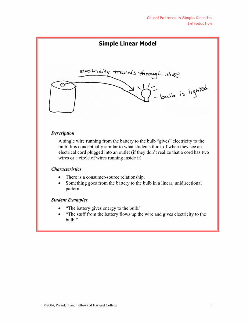
Simple Linear Model
Description
A single wire running from the battery to the bulb “gives” electricity to the bulb. It is conceptually similar to what students think of when they see an electrical cord plugged into an outlet (if they don’t realize that a cord has two wires or a circle of wires running inside it).
Characteristics
• There is a consumer-source relationship. • Something goes from the battery to the bulb in a linear, unidirectional
pattern.
Student Examples
• “The battery gives energy to the bulb.” • “The stuff from the battery flows up the wire and gives electricity to the
bulb.”

Causal Patterns in Simple Circuits: Introduction
8 ©2004, President and Fellows of Harvard College
Double Linear Model
Description
Electricity is envisioned as traveling along wires from both terminals of the battery to fuel the bulb. It may be seen as additive (traveling up both sides so there is enough) or as having attraction aspects where protons go up one wire and electrons go up the other and meet in the bulb. Attraction versions are typically held by students who know about static electricity and know that protons and electrons are attracted to each other.
Characteristics
• Often involves a consumer-source relationship between the battery and the bulb. • Something goes from the battery to the bulb in a linear, unidirectional pattern. It
does something in the bulb to make it light (feeds it, attracts, clashes, cancels out).
• Students may draw Double Linear Models but consider one wire to be a “ground,” or in some respects extra. Their underlying model is really a Simple Linear Model.
Student Examples
• “You need two wires to get enough power to make it light.” • “The electricity goes up both wires to make it light.” • “The electrons travel up one side and the protons travel up the other and they
clash together to make it light.” • “Electrons from one side of the battery and protons from the other attract and
meet in the bulb.”
Causal Patterns in Simple Circuits: Introduction
©2004, President and Fellows of Harvard College 9
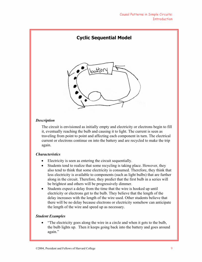
Cyclic Sequential Model
Description
The circuit is envisioned as initially empty and electricity or electrons begin to fill it, eventually reaching the bulb and causing it to light. The current is seen as traveling from point to point and affecting each component in turn. The electrical current or electrons continue on into the battery and are recycled to make the trip again.
Characteristics
• Electricity is seen as entering the circuit sequentially. • Students tend to realize that some recycling is taking place. However, they
also tend to think that some electricity is consumed. Therefore, they think that less electricity is available to components (such as light bulbs) that are further along in the circuit. Therefore, they predict that the first bulb in a series will be brightest and others will be progressively dimmer.
• Students expect a delay from the time that the wire is hooked up until electricity or electrons get to the bulb. They believe that the length of the delay increases with the length of the wire used. Other students believe that there will be no delay because electrons or electricity somehow can anticipate the length of the wire and speed up as necessary.
Student Examples
• “The electricity goes along the wire in a circle and when it gets to the bulb, the bulb lights up. Then it keeps going back into the battery and goes around again.”
Causal Patterns in Simple Circuits: Introduction
10 ©2004, President and Fellows of Harvard College
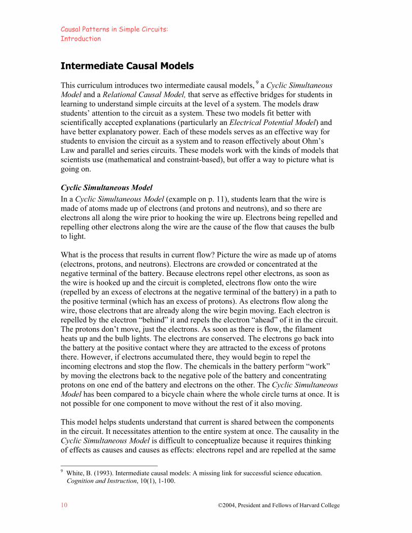
Intermediate Causal Models This curriculum introduces two intermediate causal models, 9 a Cyclic Simultaneous Model and a Relational Causal Model, that serve as effective bridges for students in learning to understand simple circuits at the level of a system. The models draw students’ attention to the circuit as a system. These two models fit better with scientifically accepted explanations (particularly an Electrical Potential Model) and have better explanatory power. Each of these models serves as an effective way for students to envision the circuit as a system and to reason effectively about Ohm’s Law and parallel and series circuits. These models work with the kinds of models that scientists use (mathematical and constraint-based), but offer a way to picture what is going on. Cyclic Simultaneous Model
In a Cyclic Simultaneous Model (example on p. 11), students learn that the wire is made of atoms made up of electrons (and protons and neutrons), and so there are electrons all along the wire prior to hooking the wire up. Electrons being repelled and repelling other electrons along the wire are the cause of the flow that causes the bulb to light. What is the process that results in current flow? Picture the wire as made up of atoms (electrons, protons, and neutrons). Electrons are crowded or concentrated at the negative terminal of the battery. Because electrons repel other electrons, as soon as the wire is hooked up and the circuit is completed, electrons flow onto the wire (repelled by an excess of electrons at the negative terminal of the battery) in a path to the positive terminal (which has an excess of protons). As electrons flow along the wire, those electrons that are already along the wire begin moving. Each electron is repelled by the electron “behind” it and repels the electron “ahead” of it in the circuit. The protons don’t move, just the electrons. As soon as there is flow, the filament heats up and the bulb lights. The electrons are conserved. The electrons go back into the battery at the positive contact where they are attracted to the excess of protons there. However, if electrons accumulated there, they would begin to repel the incoming electrons and stop the flow. The chemicals in the battery perform “work” by moving the electrons back to the negative pole of the battery and concentrating protons on one end of the battery and electrons on the other. The Cyclic Simultaneous Model has been compared to a bicycle chain where the whole circle turns at once. It is not possible for one component to move without the rest of it also moving. This model helps students understand that current is shared between the components in the circuit. It necessitates attention to the entire system at once. The causality in the Cyclic Simultaneous Model is difficult to conceptualize because it requires thinking of effects as causes and causes as effects: electrons repel and are repelled at the same
9 White, B. (1993). Intermediate causal models: A missing link for successful science education.
Cognition and Instruction, 10(1), 1-100.

Causal Patterns in Simple Circuits: Introduction
©2004, President and Fellows of Harvard College 11
time. It also requires suspending the idea of temporal priority between causes and effects. They are simultaneous or near simultaneous. It is not as easily constructed from a Simple Linear Model as a Cyclic Sequential Model is. However, it is important for understanding the circuit as a system, and it offers an explanation of what happens along a simple circuit at the level of the particle. This serves as an important bridge to models that focus on electrical potential, a less zoomed-in level of analysis, where differences in electrical charge across the entire system enable electrical vibrations to propagate through the system. Relational Model
The Relational Model (example on p. 13) underlies the scientifically accepted concept of electrical potential (sometimes called Electrical Potential or Electrical Differential Models). It focuses on differential and balance. An excess of electrons at the negative contact of the battery, and the relatively fewer electrons as well as the excess of protons at the positive contact, result in a differential so that the electrons flow away from areas of higher concentration to areas of lower concentration of electrons. The chemicals in the battery perform “work” by concentrating net protons on one end of the battery and net electrons on the other. This is work because the protons and electrons are attracted to each other, and creating an excess of electrons (which repel each other) and protons (which repel each other) requires energy. The excess of electrons at the negative contact and the depletion of electrons at the positive contact, as well as the excess of protons, create a differential so that the electrons flow away along the circuit path from the area of higher concentration to the area of lower concentration of electrons. The concept of electrical potential involves relational causal reasoning, where students need to think about the relationship between two variables as the cause of an outcome rather than one variable or one event as the cause. This form of causality departs significantly from linear or additive forms of causality. The Relational Model helps students understand why electrical impulses propagate along the wire and offers an important segue into thinking about the circuit using Ohm’s Law and the constraints of voltage, resistance, and ultimately current. It takes into account the entire system and how different variables impact it.
Causal Patterns in Simple Circuits: Introduction
12 ©2004, President and Fellows of Harvard College
Cyclic Simultaneous Model
Description
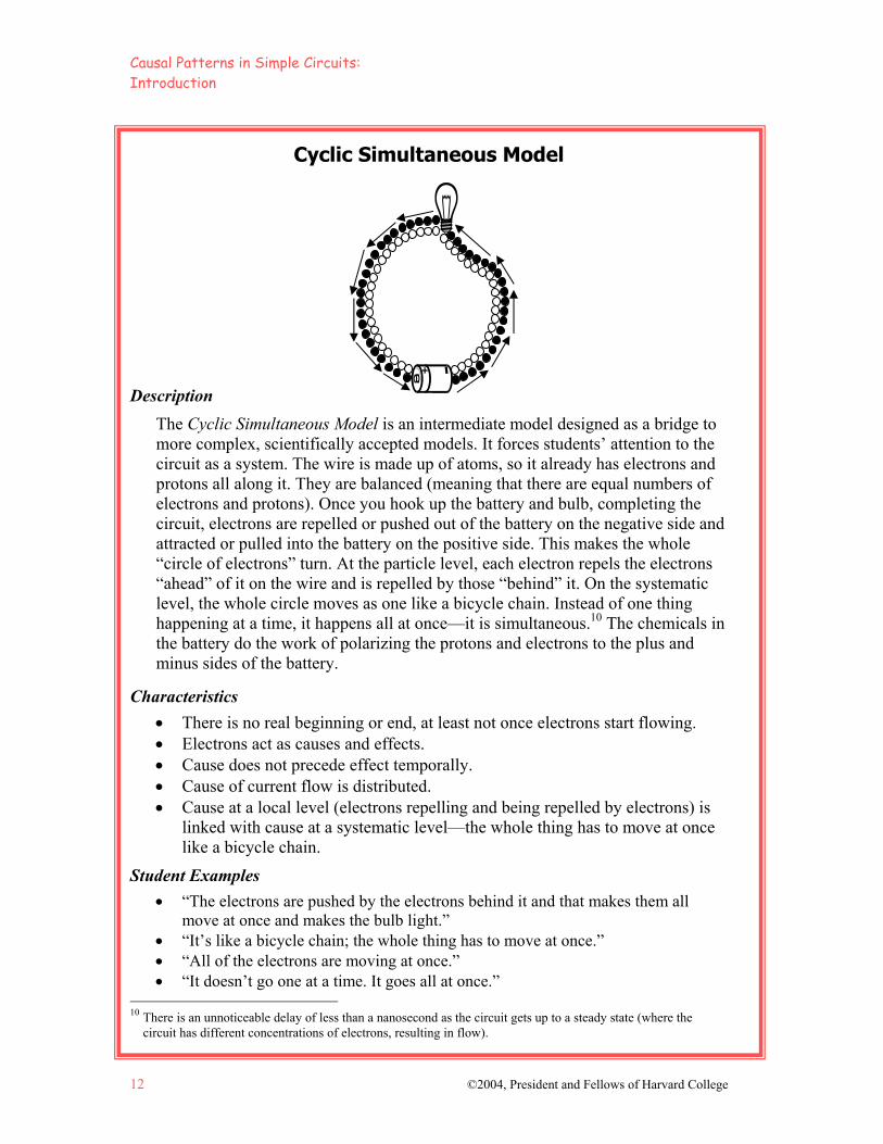
The Cyclic Simultaneous Model is an intermediate model designed as a bridge to more complex, scientifically accepted models. It forces students’ attention to the circuit as a system. The wire is made up of atoms, so it already has electrons and protons all along it. They are balanced (meaning that there are equal numbers of electrons and protons). Once you hook up the battery and bulb, completing the circuit, electrons are repelled or pushed out of the battery on the negative side and attracted or pulled into the battery on the positive side. This makes the whole “circle of electrons” turn. At the particle level, each electron repels the electrons “ahead” of it on the wire and is repelled by those “behind” it. On the systematic level, the whole circle moves as one like a bicycle chain. Instead of one thing happening at a time, it happens all at once—it is simultaneous.10 The chemicals in the battery do the work of polarizing the protons and electrons to the plus and minus sides of the battery.
Characteristics
• There is no real beginning or end, at least not once electrons start flowing. • Electrons act as causes and effects. • Cause does not precede effect temporally. • Cause of current flow is distributed. • Cause at a local level (electrons repelling and being repelled by electrons) is
linked with cause at a systematic level—the whole thing has to move at once like a bicycle chain.
Student Examples
• “The electrons are pushed by the electrons behind it and that makes them all move at once and makes the bulb light.”
• “It’s like a bicycle chain; the whole thing has to move at once.” • “All of the electrons are moving at once.” • “It doesn’t go one at a time. It goes all at once.”
10 There is an unnoticeable delay of less than a nanosecond as the circuit gets up to a steady state (where the
circuit has different concentrations of electrons, resulting in flow).
Causal Patterns in Simple Circuits: Introduction
©2004, President and Fellows of Harvard College 13
Relational Model
Description
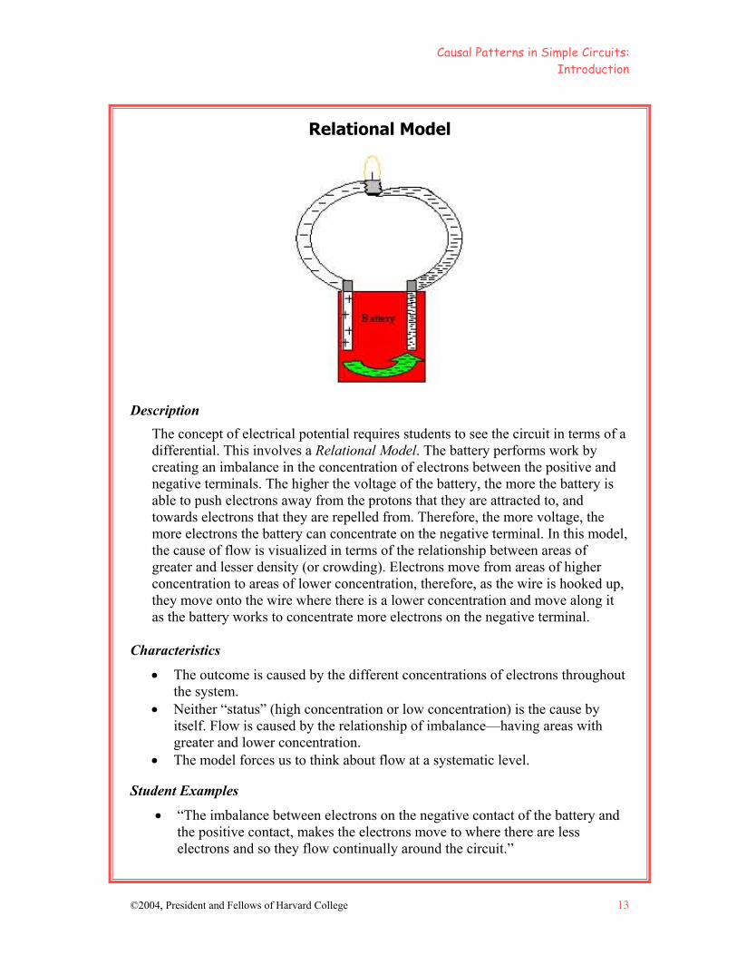
The concept of electrical potential requires students to see the circuit in terms of a differential. This involves a Relational Model. The battery performs work by creating an imbalance in the concentration of electrons between the positive and negative terminals. The higher the voltage of the battery, the more the battery is able to push electrons away from the protons that they are attracted to, and towards electrons that they are repelled from. Therefore, the more voltage, the more electrons the battery can concentrate on the negative terminal. In this model, the cause of flow is visualized in terms of the relationship between areas of greater and lesser density (or crowding). Electrons move from areas of higher concentration to areas of lower concentration, therefore, as the wire is hooked up, they move onto the wire where there is a lower concentration and move along it as the battery works to concentrate more electrons on the negative terminal.
Characteristics
• The outcome is caused by the different concentrations of electrons throughout the system.
• Neither “status” (high concentration or low concentration) is the cause by itself. Flow is caused by the relationship of imbalance—having areas with greater and lower concentration.
• The model forces us to think about flow at a systematic level.
Student Examples
• “The imbalance between electrons on the negative contact of the battery and the positive contact, makes the electrons move to where there are less electrons and so they flow continually around the circuit.”
Causal Patterns in Simple Circuits: Introduction
14 ©2004, President and Fellows of Harvard College
The Connection Between Current Flow and the Bulb Lighting Why does the bulb light when there is current flow? Characteristics of the wire inside the bulb (known as the filament) make it difficult for electrons to move along it. Impeding the flow of electrons results in energy transfer that heats the filament, which becomes hot enough to glow and give off light. One way to help students move beyond the notion, that in order to produce light something must be used up, is to consider the analogy of a water wheel. In a water wheel there is turning without using something up. However, the concept is even more complex than the analogy accounts for. Eventually, the link must be made between flow and the creation of light and heat11 (as explained in the background notes to Lesson 4). Helping Your Students Achieve Deeper Understanding The activities in this module are designed to reveal your students’ current causal models, and to help them progress towards models that have greater explanatory power. It is likely that your students’ ideas will fall along a continuum of the models presented in these lessons and that they will hold many of the misconceptions related to the particular model. Some students may hold a combination of models or idiosyncratic versions of these or other models. However, a wealth of research suggests that these models outline the kinds of ideas your students bring to their learning. It is important to note that the kinds of models presented here are conceptual models. They are not the same as the schematic diagrams that electricians draw to illustrate different kinds of circuit configurations and that some science curriculums attempt to teach. The models here attempt to illuminate why circuits work, to the extent of our scientific understanding and at a level that provides effective models from which middle school students can reason.
11 Ideas from Eric Buchovecky.
Causal Patterns in Simple Circuits: Introduction
©2004, President and Fellows of Harvard College 15
Instructional Approach The activities in this module are based on a set of pedagogical assumptions and are best supported by a certain type of classroom culture as outlined below:
• Gear your classroom culture towards developing understanding, not just “right answers.” Deep understanding enables students to apply their knowledge in authentic contexts beyond the original learning context. It takes longer to develop but the pay-off is greater.
• Provide opportunities for students to engage in the kind of scientific inquiry that scientists engage in—where the process of learning the subject matter mimics the process of “finding out”. However, not all learning can be inquiry-based or constructivist. Students also need exposure to the models that scientists have evolved during centuries of scientific inquiry.
• Students already hold general principles about how the world works. These are based on their own sense making. Often students don’t explicitly know what assumptions they are making. They need opportunities to reflect on their own thinking. Drawing, explaining, and discussing their ideas can help.
• Students won’t really change their minds until their objections have been dealt with and the evidence is convincing to them. Their most challenging questions can drive a discussion towards more sophisticated models.
• Science involves the systematic discard and revision of models for ones with greater explanatory power. Understanding evolves in a similar way. Expect students to move through the models towards scientifically accepted models, but understand that they won’t all accept the scientific model before the end of the unit.
• Encourage testing and revising one’s model over “getting it right.” Students who adopt the “right” model without deeply reasoning it through are likely to revert to their less evolved models as soon as the unit ends.
• Encourage students to take risks in their thinking and to test their ideas in a social context. Instead of shooting ideas down, consider the relevant evidence.
• Encourage students NOT to just accept ideas because someone else says they should. They should change their ideas when the evidence is convincing to them.
• No model explains everything about a particular phenomenon. Each model works in some ways and not in others. Models should be critiqued as a regular part of classroom discussions. Some models have more explanatory power than others, but no model captures the whole idea.
• Encourage students to generate “rival models”—two different ways of explaining the same event—as often as possible. This helps them to view the models more flexibly and to resist becoming overly invested in one model. However, if students already have a firm idea in mind, they often aren’t able to generate two possibilities and need to grapple with their current model.


©2004, President and Fellows of Harvard College 17
LESSON 1 WHAT CONFIGURATIONS WORK
TO LIGHT A BULB?
This lesson invites students to experiment with different battery and bulb configurations to discover that linear arrangements do not work to light the bulb. Students are encouraged to find different ways to light the bulb using just a wire and a battery. There are versions of this lesson in most
hands-on materials for elementary students.
Additional Resources for Lesson 1
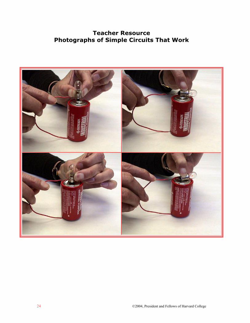
Simple Circuits: What Works? sheet Teacher Resource: Photographs of Simple Circuits That Work
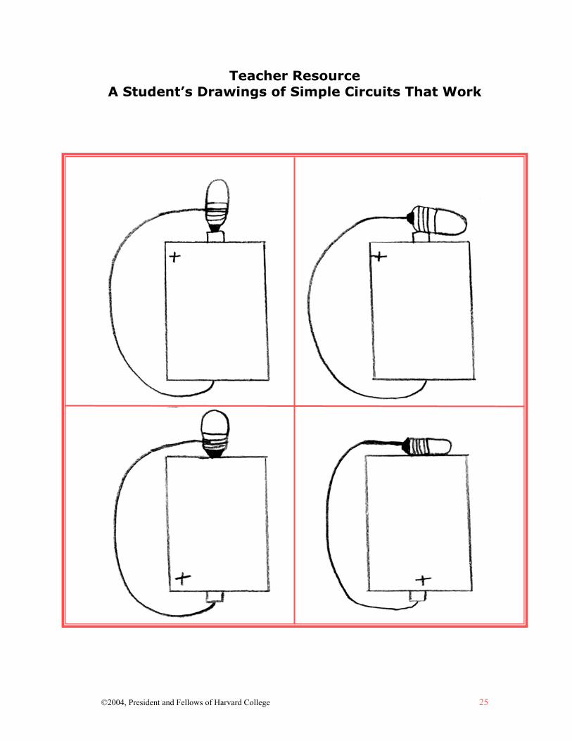
Teacher Resource: A Student’s Drawings of Simple Circuits That Work Student Examples of Simple Circuits: What Works?

©2004, President and Fellows of Harvard College 19
Lesson 1: What Configurations Work to Light a Bulb?
Understanding Goals Subject Matter
It is possible to light a bulb with just a wire and a battery. Four configurations with one wire and a battery work to light the bulb. We all have implicit models for what we think is going on when the bulb
lights. Causality
A Simple Linear Model does not explain how a simple circuit works. It is important for us to unpack our own causal models for what makes the
bulb light and to revise them as suggested by the evidence.
Background Information Finding Configurations That Light the Bulb
In this lesson, students experiment with lighting a bulb using a single wire and a battery. Many students think that it is impossible to do this with just one wire and are surprised to discover that it is not only possible, but that there is more than one configuration that works. For this initial exploration, students should work individually so that each student has a chance to explore his or her current conceptions. They are encouraged to try to find as many different configurations as they can. Students are purposely not given battery or bulb holders because they tend to think that the bulb holder is necessary for the bulb to light. Implicit Causal Models Impact Which Configurations Students Try
Students typically have implicit causal models for what is going on, but the focus of this lesson is on finding configurations that work. The link to underlying causal models will be the explicit focus of the next lesson. After the exploration, students are asked to reflect on what causal models they hold. Students typically begin trying to light the bulb by attaching the wire to the battery such that one wire connects the battery directly to the bulb so electrons can flow in one direction from the battery to the bulb. They may be surprised when this doesn’t work because it fits with their notion of what it means to “plug something in.” (For this reason, an activity later in the unit involves separating some extension cords.) Some students believe that they need two wires to light the bulb. These students are often surprised to find that they don’t.
Causal Patterns in Simple Circuits: What Configurations Work to Light a Bulb?
20 ©2004, President and Fellows of Harvard College
Lesson Plan Materials
Wire, (insulated copper wire with plastic coating, apx. 6 inches long with copper ends exposed), 2 per student
“D” cell batteries, 1 per student Flashlight Bulbs, 1 per student (have a few extra bulbs on hand in case one is
dropped) Simple Circuits: What Works? sheet, 1 per student
Prep Step
Review the lesson plan, background information, and understanding goals. Gather batteries, bulbs and wire. Test all bulbs and batteries to ensure that they are working properly. Photocopy the sheet, Simple Circuits: What Works? (pp. 22-23).
Analyze Thinking Step 1: Considering Initial Models
Explain to the students that they will be learning about how simple electrical circuits work. As a safety precaution, stress that while this unit will help them understand some things about the electricity in their homes, they should never experiment with electricity at home. It is very dangerous to do so. The batteries used in class have a voltage that is low so that the students will not be hurt. This is not true of the electricity in their homes.
Show the students a battery, a bulb, and one wire. Ask them to think about what they would do if they wanted to light the bulb using the wire and the battery. Ask them to draw a diagram on paper or in their journals, and under their diagram to explain why it would work. As students are working, circulate to see what kinds of models they are drawing. Most students typically draw a Simple Linear Model as outlined in the introduction.
RECAST Thinking Step 2: Discovering That Linear Configurations Don’t Work
Pass out the Simple Circuits: What Works? sheet, a battery, a bulb, and one wire to each student (the second wire will be passed out later in the lesson). Explain to your students that their challenge is to try to light the bulb using just the materials that you have given them. Make sure that students record ALL of the configurations that they try, even those that don’t work. Finding patterns in what doesn’t work is as important as finding patterns in what does work for developing

Causal Patterns in Simple Circuits: What Configurations Work to Light a Bulb?
©2004, President and Fellows of Harvard College 21
a good explanatory model. Explain that it might take them a while to find ways that work. That is fine. The idea is to explore possible configurations until they find some that do work. Circulate while students are working. Ask:
• Why do they think different arrangements are working? What do they think is going on? (Tell your students that there are at least four configurations that work to light the bulb.)
After students have successfully figured out how to light the bulb with a battery and one wire in four different ways, give them a second wire and see if they can apply what they have learned to lighting the bulb using two wires instead of one. Surprisingly, some students are initially uncertain about how to use two wires and grappling with the second wire reinforces what it is about the configurations that work. Afterwards, students may continue to experiment. Encourage this experimentation by offering additional wires, bulbs, and batteries. Ask students to predict whether certain arrangements work and what they found out when they tried them.
Explore Causality Step 3: Revising Initial Models
Have students consider the following questions:
• What similarities are there between the arrangements that work? • What differences are there between those that work and those that don’t? • What do you think is going on at the atomic level (electrons, protons, and
neutrons) when the bulb lights? Have students revise the models that they drew at the beginning of the class. After they have drawn one model, have them create a rival model by drawing a second diagram that is different from their first diagram, but that also could explain what is going on.
Review, Extend, Apply Step 4: Making Connections
Encourage students to take a look at battery-operated toys and other devices (such as flashlights and clocks) at home, and to note the ways batteries are connected to the devices. What similarities do they see compared to the configurations that they created in class?

22 ©2004, President and Fellows of Harvard College
Name Date
Simple Circuits: What Works? Draw diagrams of the configurations that worked to light the bulb using the battery and the wire. Make sure it’s clear which end of the battery is which and exactly where you are attaching the wire.
©2004, President and Fellows of Harvard College 23
Draw diagrams of configurations that did NOT work to light the bulb using the battery and the wire.
24 ©2004, President and Fellows of Harvard College
Teacher Resource Photographs of Simple Circuits That Work
©2004, President and Fellows of Harvard College 25
Teacher Resource A Student’s Drawings of Simple Circuits That Work
Student Example Simple Circuits: What Works?
26 ©2004, President and Fellows of Harvard College
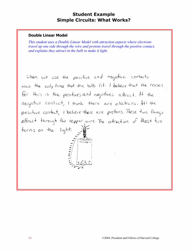
Double Linear Model
This student uses a Double Linear Model with attraction aspects where electrons travel up one side through the wire and protons travel through the positive contact, and explains they attract in the bulb to make it light.
Student Example Simple Circuits: What Works?
©2004, President and Fellows of Harvard College 27
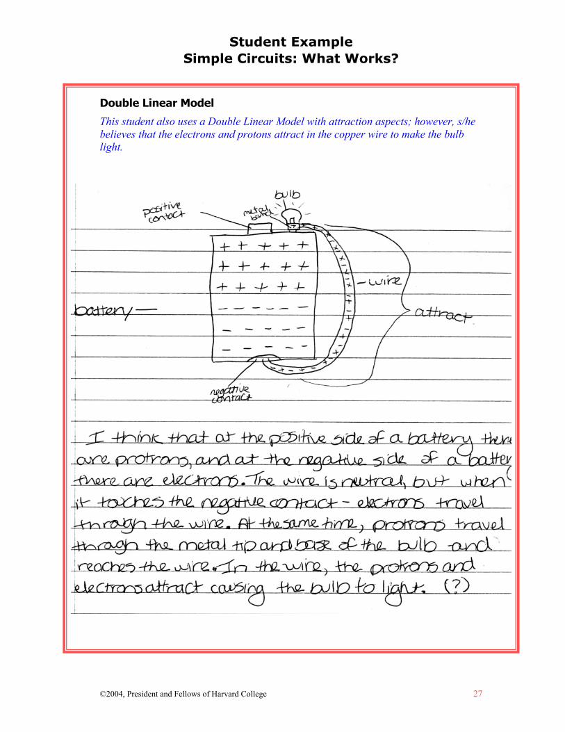
Double Linear Model
This student also uses a Double Linear Model with attraction aspects; however, s/he believes that the electrons and protons attract in the copper wire to make the bulb light.

Student Example Simple Circuits: What Works?
28 ©2004, President and Fellows of Harvard College
Cyclic Sequential Model
This student uses a Cyclic Sequential Model where the bulb lights as the electrons and protons reach the filament. The student believes that protons also travel. The student’s language in the last sentence is consistent with a Cyclic Simultaneous Model and may suggest that the student is beginning to understand some aspects of that model.

Student Example Simple Circuits: What Works?
©2004, President and Fellows of Harvard College 29
Simple Linear Model
This student uses a Simple Linear Model. Even though s/he illustrates the circuit with a cyclic configuration, s/he explains it as a simple linear, consumer-source model where electricity travels from the battery to the bulb to make it light.


©2004, President and Fellows of Harvard College 31
LESSON 2 WHAT IS THE UNDERLYING
CAUSALITY OF A SIMPLE CIRCUIT?
This lesson asks students to unpack their implicit causal models and to consider a Cyclic Simultaneous Model for explaining electrical flow at the
particle level. It aims to help students move beyond Simple Linear or Cyclic Sequential Models. They discuss the models that they hold for how a simple circuit works in light of the supporting evidence. The Cyclic Simultaneous
Model for energy flow is introduced and critiqued along with the other models.
Additional Resources for Lesson 2
Picture of Practice How to Open a Light Bulb Without Breaking the Insides
Photograph of the Inside of a Light Bulb Photograph and Diagram of Household Bulb With Base
Photograph and Diagram of Household Bulb Without Base Bulb and Battery Circuit Model
Shower Curtain Illustration Using Cyclic Simultaneous Causality to Explain the Simple Circuit sheet
Thinking About Causality and the Simple Circuit: Why is it so Hard? sheet


©2004, President and Fellows of Harvard College 33
Lesson 2: What is the Underlying Causality of a Simple Circuit?
Understanding Goals Subject Matter
Electrons are conserved in a circuit. The bulb lights when electrons flow in the circuit. Flow requires a continuous
“push.” The battery does “work” by providing push or tension. Voltage can be thought of simply as push, or the force that moves electrons. The circuit is process-like, not substance-like. There is no point at which the
circuit is “empty.” Everything is made up of atoms; therefore, there are electrons all along the wire at all times.
Causality
At the particle level, the causality in a Cyclic Simultaneous Model explains the process of flow better than Simple Linear or Cyclic Sequential Models. It involves thinking about the entire circuit as a system.
In the Cyclic Simultaneous Model, electrons repel and are repelled by those around them. In essence, cause is effect and effect is cause. This results in flow.
The battery completes the Cyclic Simultaneous Model by pushing the electrons back to the negative contact.
It can be difficult to move beyond linear models of electrical flow. Many everyday experiences encourage us to view it as a linear process (such as one-way electrical cords coming out of appliances).
Background Information Revealing the Causal Models Implicit in Students’ Configurations
The purpose of this lesson is to get students to reflect upon and, hopefully, begin revising their mental models of how a simple circuit works. Setting up configurations of circuits that work and don’t work, as in Lesson 1, is a way to get students thinking about their models. However, while students realize pretty quickly that a simple linear arrangement doesn’t work, they tend to cling to aspects of theunderlying Simple Linear Model. There are a number of things that students may say
Causal Patterns in Simple Circuits: What is the Underlying Causality of a Simple Circuit?
34 ©2004, President and Fellows of Harvard College
and do that will alert you to whether students truly have a cyclic model or are holding onto their linear models. For instance, some students say that the wires need to be in a circle, but they may think, “the other wire is just a ground.” Some students understand the cyclic aspects of the circuit but say things like, “the wire is empty and the electrons travel to the bulb and light it up when they reach the bulb.” These students often (erroneously) believe that if you extend the length of the wire, it will take longer for the bulb to light. In order to prepare for this lesson, it is important that you carefully review the progression of models outlined on pages 4 to 9. You will most certainly recognize these models in your students’ thinking. Because most students (and sometimes teachers) get stuck at a Cyclic Sequential Model and find it hard to make the leap to the Cyclic Simultaneous Model, this lesson focuses directly on this conceptual leap. If you find that your students are stuck at an earlier point in the progression, you will need to address those models first. Moving Beyond the Cyclic Sequential Model
You can help your students move beyond the Cyclic Sequential Model by helping them realize that all matter is made up of atoms (which are made up of electrons, protons, and neutrons); and that therefore the circuit cannot be “empty.” It is made up partly of electrons. Many students think of electrons as flowing “inside” the wire. Try to make them aware of this and the language that they use to reveal it. Encourage them to see the electrons as part of the metal that is conducting charge. You can also ask students to think about what happens when they flip a light switch. Do the lights on the end of the hallway take a perceptibly longer time to come on than those at the beginning of the hallway? Most students realize that this is not the case. However, don’t be surprised if your students patch their current model by saying things like, “the electrons just speed up because they know that they have to go further.” It can be difficult to give up a mental model that you strongly believe in! Introducing the Cyclic Simultaneous Model The Cyclic Simultaneous Model is an intermediate model designed as a bridge to more complex scientifically accepted models. It draws students’ attention to the circuit as a system. How does it work? The wire is made up of atoms, so it already has electrons and protons all along it. They are balanced. Once you hook the battery and bulb up completing the circuit, electrons are repelled or pushed out of the battery on the negative side and attracted or pulled into the battery on the positive side. This makes the whole “circle of electrons” turn. At the particulate level, each electron repels the electrons “ahead” of it on the wire and is repelled by those “behind” it. On the systematic level, the whole circle moves as one, like a bicycle chain. Instead of one thing happening at a time, it happens all at once—it is simultaneous.

Causal Patterns in Simple Circuits: What is the Underlying Causality of a Simple Circuit?
©2004, President and Fellows of Harvard College 35
What is the Role of the Battery in the Cyclic Simultaneous Model?
Understanding this model also depends upon having some knowledge of what the battery does. Later in the module, an in-depth lesson explores the role of the battery to support understanding of an Electrical Potential Model. However, the following information is enough to understand the Cyclic Simultaneous Model. Why is the push of the battery important if electrons are being repelled and repelling all along the wires in the circuit? Why doesn’t this repelling continue to create flow? In the Cyclic Simultaneous Model, something needs to keep the “bicycle chain” turning, so to speak. Without the push of the battery, the electrons would be attracted to the protons and stay at the positive contact. Students may realize that once electrons flow into the positive terminal and accumulate there, they could begin to repel the incoming electrons and stop the flow. Why don’t they? The battery addresses this problem by accomplishing the task of moving the electrons back to the negative contact of the battery. The chemicals in the battery do the work of polarizing the protons and electrons to the plus and minus sides of the battery. The “work” of the battery results in an excess of protons on one end of the battery and an excess of electrons on the other. This is work because the protons and electrons are attracted to each other, and creating an excess of electrons (which repel each other) and protons (which repel each other) requires energy, which is provided by the chemicals in the battery. So what is voltage? The battery is performing work. The negatively charged electrons are attracted to the protons. The higher the concentration of electrons on the negative terminal, the harder it is for the battery to push more electrons onto it. The higher the voltage of the battery, the greater chemical capacity it has to concentrate electrons on the negative contact. Voltage can be thought of simply as a push, or the force that moves electrons. Lesson 8 introduces a more complex way to think about voltage.
Causal Patterns in Simple Circuits: What is the Underlying Causality of a Simple Circuit?
36 ©2004, President and Fellows of Harvard College
Lesson Plan Materials
White boards (apx. 1½ x 2 feet) or pieces of large paper to draw models Bulb with glass top removed Shower curtain, preferably white or off-white, with circuit drawn on it; or a
white board with circuit drawn on it and black and white magnetic disks Tennis balls, 4 Tennis ball can, 1 (2 cans can be taped together for a longer model) Clear tubing, apx. 3 feet in length, 1 ½ inches in diameter (available at most
hardware stores) Black and white marbles, apx. 100 of each Comparing Causal Models for Electricity, CD-ROM of computer models that
accompanies this module Using Cyclic Simultaneous Causality to Explain the Simple Circuit sheet Thinking About Causality and the Simple Circuit: Why is it so Hard? sheet
Prep Step
Review the lesson plan, background information, and understanding goals. Remove the top of a bulb (following the directions on p. 46 and see example
on p. 47) so that students can see the wires and their placement. Draw a circuit pattern with battery, bulb and wires on the shower curtain. The
drawing should be large enough to fill the shower curtain. See the Bulb and Battery Circuit Model (p.52) and a photograph of what a finished shower curtain looks like (p. 53).
Gather black and white marbles, dividing the lot so that there are enough to fill the clear tubing and reserving the rest to demonstrate the flow of electrons on the shower curtain model (see pp. 39-40).
Gather clear tubing. Fill the tube with black and white marbles side by side and tape the tubing closed to keep marbles from escaping (see p. 40).
Gather the tennis ball canister and balls. Cut the bottom off of the tennis can and remove the label (see p. 41).
Have computer and monitor set up for the software simulation, Comparing Causal Models for Electricity.
Photocopy the sheets Using Cyclic Simultaneous Causality to Explain the Simple Circuit and Thinking About Causality and the Simple Circuit: Why is it so Hard? (pp. 54-56).
Read the Picture of Practice (pp. 44-45).
Causal Patterns in Simple Circuits: What is the Underlying Causality of a Simple Circuit?
©2004, President and Fellows of Harvard College 37
Analyze Thinking
Step 1: Analyzing Configurations That Work to Find Patterns
Have students put the configurations of the four models that they worked on from the previous lesson on the board. Discuss what is similar and different about them. Also, ask a few students to explain what their explorations were like. What are some of the first things they tried? What did they learn from it? What are some of the later things that they tried and what made them decide to try these things?
Explain to the students that this lesson will focus on the models that they drew to explain the simple circuit following Lesson 1. However, before doing that, you’d like to share some additional information and give them a chance to revise their models in whatever ways make sense to them given the new information.
Step 2: Considering How the Bulb is a Part of the Model
Ask the students to do a quick sketch in their journals or on a sheet of paper of what they think the inside of a bulb looks like based on their observations from the previous lesson. Give them a few moments to draw what they infer must be inside.
Invite some students to share their ideas. Next, show students a bulb with the top removed. (Refer to How to Open a Light Bulb Without Breaking the Insides for instructions, pp. 46-47). Point out the wire coming out the side of the bulb and the other wire coming from the bottom of the bulb and be sure that students note the arrangement of the wires. How do these spots correspond to where they put their wire or battery contacts to light the bulb? Have them refer back to their sheets, Simple Circuits: What Works? to remind them of their findings.
Step 3: Analyzing Revised Student Models
Ask all of the students to choose one of the models that they did for Lesson 1, Step 3 and draw it on an individual white board. They should feel free to revise their model based upon what they now know about the design of a bulb.
As students are working, circulate and look for a representative set of models to focus the class discussion. Try to include examples of Simple Linear Models, Double Linear Models, Cyclic Sequential Models, and if any students have created them, Cyclic Simultaneous and/or Relational Models. Ask these students to share their models with the class.
Discuss each of the models in turn. It helps to structure the conversation by beginning with a Simple Linear Model, moving next to a Double Linear Model, and then to a Cyclic Sequential Model (and if anyone drew them, Cyclic Simultaneous or Relational Models). Remind the class that models typically work in some ways and not others. When considering the models, they should think about what evidence it helps to explain and what evidence it doesn’t. Guide the discussion in this direction as students share their ideas.

Causal Patterns in Simple Circuits: What is the Underlying Causality of a Simple Circuit?
38 ©2004, President and Fellows of Harvard College
Note to Teacher: A good assessment that can be conducted at this point in the unit, and again at the end, is to ask students what would happen if you increased the length of the wire between the battery and the bulb. Students will often say that it will take longer for the bulb to light and that the difference is observable. Others will say that the electrons just "know" that they have further to travel so they speed up. Others may realize that it won't take longer (not in any way that anyone could notice)1 because there are atoms making up the wire (that are in turn made up partly of electrons).
1 There is an unnoticeable delay of less than a nanosecond as the circuit gets up to steady state (where
the circuit has different concentrations of electrons, resulting in flow).
Recast Thinking
Step 4: Comparing How Well the Models Explain the Simple Circuit
To help students evaluate the various models, offer the following information. Share the rule that electrons are conserved. They don’t disappear or get used up. What does this suggest for the models on the board? There has to be a place for the electrons to go. Electrons are atomic particles that make up matter. They are very tiny, but still they are “stuff.” Which models violate that principle? Which ones follow it? Guide students to the realization that models that have an end, such as the Simple Linear or Double Linear Models, violate this principle.
Focus on the cyclic models on the board. Typically a couple of students have drawn a Cyclic Sequential Model. If this is not the case, draw one on the board and ask students to explain how it works. Ask why the cyclic part is important. Explain that you will be illustrating some different ways to think about the cyclic models to help students see how their models work and how they could work better.
The following activities illustrate aspects of the abstract process of electrical flow and offer ways to introduce the Cyclic Simultaneous Model. Use one or both activities to focus the discussion of models with your students.
Step 5a: Contrasting the Cyclic Sequential and Cyclic Simultaneous Models Using the Shower Curtain Illustration
This illustration uses a shower curtain with a circuit pattern drawn on it, some clear plastic tubing, black and white marbles, a clear tennis can with the bottom removed, and four tennis balls. The shower curtain shows a cyclic path. As an alternative to using the shower curtain and marble model, one teacher recommended drawing the model on a whiteboard and using black and white magnetic disks to represent the circuit and flow of electrons and protons.

Causal Patterns in Simple Circuits: What is the Underlying Causality of a Simple Circuit?
©2004, President and Fellows of Harvard College 39
Set the shower curtain out on the floor and gather students around it. Explain that it shows a battery, a wire “path,” and a bulb, and that you are going to use it to show them the difference between a model called a Cyclic Sequential Model and one called a Cyclic Simultaneous Model. Write each term on the board.
First, talk about the Cyclic Sequential Model with your students. Explain that this model is similar to what many of them drew and to what a lot of people (including adults) believe. In the battery, there is a concentration of electrons at the negative contact and a concentration of protons at the positive contact. Illustrate this by putting white marbles for protons at the positive contact and black marbles for electrons at the negative contact. When the battery is hooked up electrons start to flow onto the wire path, through the bulb, and to the positive terminal. Put some black marbles at the “beginning” of the path to illustrate electrons moving onto the wire.
Example of a Cyclic Sequential Model
Discussion of a Cyclic Sequential Model Using the Shower Curtain Illustration
Electrons flowing to the bulb and positive terminal
Black Marbles = Electrons
White Marbles = Protons
Causal Patterns in Simple Circuits: What is the Underlying Causality of a Simple Circuit?
40 ©2004, President and Fellows of Harvard College
Ask: • What makes the electrons move onto the wire? The other electrons at the
negative terminal repel them and so they move away. The lower concentration of electrons on the wire allows electrons from the battery to move onto the wire and fill it up.
• What makes the bulb light up in this model? When the electrons reach the bulb, the bulb lights. Then the electrons keep on going and go back to the battery and to the positive terminal.
• What are some things that work about this model? It explains the cyclic configurations. It recycles electrons so they don’t get stuck anywhere.
• What are some things that don’t work about the model? It doesn’t explain why, if the electrons don’t immediately reach the bulb, it still lights right away, with no time delay. It shows the wire as empty, and because the wire is made of electrons and protons, it cannot ever be empty.
You can test whether or not is actually takes time for the electrons to reach the bulb by increasing the length of the wire to see what happens. (For this you will need a piece of wire that is at least one to two feet in length.) Students will not be able to perceive any difference. However, this is not necessarily convincing evidence for a few reasons:
• Some students will think that if the light switch is far from the lights, the electrons can just speed up at will;
• Some students think that electricity “travels” so fast that you couldn’t see a difference anyway; and
• There actually is a small imperceptible transient delay in the measure of nanoseconds. This is because it can take a small amount of time for the circuit to reach “steady state” (where the circuit has different concentrations of electrons, resulting in flow, as explained in Lesson 8).
Connect this to their real world knowledge. Ask:
• If there were an electrical outage in your neighborhood, would all the lights go out and come back on at once or in a sequential pattern?
• What do you know about the nature of matter? All matter is made up of atoms, which are made up of electrons, protons, and neutrons.
Another problem with the Cyclic Sequential Model is that it doesn’t take into account that the wire is made up of atoms and atoms are made up of protons and electrons. The wire can’t possibly be “empty.”

Causal Patterns in Simple Circuits: What is the Underlying Causality of a Simple Circuit?
©2004, President and Fellows of Harvard College 41
Next contrast the Cyclic Sequential Model to another model that fits a little better with how scientists think about what is happening: the Cyclic Simultaneous Model. Line the entire wire path with white and black marbles next to each other—proton and electron “partners” (or explain that the entire path would be lined with electrons and protons). Ask:
• What will happen as electrons come in contact with other electrons? Students who understand static electricity will realize that each electron will be repelled by the electron “behind” it and will repel the electron “ahead” of it in the circuit.
Explain to your students that in the Cyclic Simultaneous Model, the wire already has electrons all around it and when you hook up the wire, each electron begins to repel (and be repelled by) the ones on either side of it. Each electron is a cause and an effect. It causes the one beyond it to move at the same time that the one behind it causes it to move. It is like a bicycle chain: the whole thing moves at once. Electrons move or flow along the path. Protons stay where they are. Discuss the process of the electron movement as simultaneous; that it happens all at once. Show students a tube filled with marbles to convey the idea that all of the electrons have to move together, when more are put in the end, more move out the other end. It can be difficult to get the black and white marbles lined up in the tube to show just the black ones moving. At this point, you could just fill the tube with black ones as long as your students are aware that the protons are still there.
Example of a Cyclic Simultaneous Model
Protons stay where they are
Electrons move

Causal Patterns in Simple Circuits: What is the Underlying Causality of a Simple Circuit?
42 ©2004, President and Fellows of Harvard College
It can be tricky to line the marbles up in the tube so that the white ones are all on one side and the black ones on the other. There’s no need to worry about this. How the marbles line up in the tube invites a nice opportunity to discuss the nature of models. No model is the same as the actual phenomenon it attempts to show. It represents the phenomenon and makes certain compromises in the process. Ask students to consider in what ways the marbles in the tube are like the electrons and protons along a circuit and in what ways they are not. How would the actual electrons and protons behave? Students might make some of the following critiques of the model: There are many, many electrons and the electrons are actually much smaller than the protons. They are not neatly matched, one to one with a partner. There is no such thing as a static model and that electrons would not just sit next to other electrons as in the marble tube, and so on.
You can also show this idea with a tennis ball can and some tennis balls as well: as you push one ball in, another one comes out. Explain that the tennis can and clear tubing with marbles work to show the kind of movement, but they are not good models in the sense that they look “filled up.” The idea is more that there are electrons all along the wire because the wire is made up of them, not so much because it is “filled up.”
Marble Illustration of Cyclic Simultaneous Model
Setting up the Tube and Marbles
Causal Patterns in Simple Circuits: What is the Underlying Causality of a Simple Circuit?
©2004, President and Fellows of Harvard College 43
Another way to show the illustration is to have students role-play the parts of electrons and protons. In order to differentiate electrons from protons, give students tags of opposite colors or tags with pluses and minuses, or choose students wearing opposite color shirts. Acting out the scenario engages students in thinking through the behavior of protons and electrons. However, it is slightly more difficult to visualize the overall process when one is playing a particular role in it. Therefore, some teachers have opted to have the straight discussion to introduce the ideas and then act it out to reinforce those ideas. Step 5b: Contrasting the Cyclic Sequential and Cyclic Simultaneous Models Using the Software Simulation
Another way to contrast the two models is by using the software, Comparing Causal Models for Electricity provided with this module. Even if you do the shower curtain illustration, you can use the software simulation to reinforce the concepts. As you talk about the computer simulation, engage students in the conversation outlined above for the shower curtain illustration. The software simulation shows both the Cyclic Sequential and Cyclic Simultaneous Models. It gives some other options that you may wish to use depending upon what ideas the students bring to the unit. For instance, you can turn the protons on or off, and show both protons and electrons moving (though only the electrons actually move in the circuit). These options are given because they fit with ideas that students tend to bring to the unit and provide a means for teachers to address those ideas.
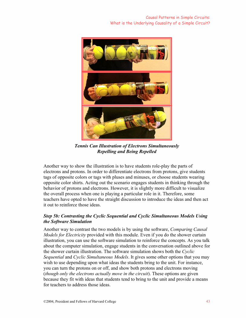
Tennis Can Illustration of Electrons Simultaneously Repelling and Being Repelled
Causal Patterns in Simple Circuits: What is the Underlying Causality of a Simple Circuit?
44 ©2004, President and Fellows of Harvard College
Step 6: What is the Role of the Battery in the Cyclic Simultaneous Model?
Some students will realize that the electrons are going towards the positive contact of the battery as electrons are attracted to the excess of protons there. Scientists think of the primary force as a push from the electrons behind, but students may also think of it as a pull from the protons in the battery. Students may also realize that once electrons flow into the positive terminal and accumulate there, they could begin to repel the electrons and stop the flow. Why don’t they? This question leads nicely into a discussion of the role of the battery. Explain to the students that the “work” of the battery is to move charges, which results in an excess of protons on one end of the battery and an excess of electrons on the other end. This is work because the protons and electrons are attracted to each other, and creating an excess of electrons (which repel each other) and protons (which repel each other) requires energy that is provided by the chemicals in the battery. In Lesson 8, students will learn that the excess of electrons at the negative contact, and a depletion of electrons at the positive contact (leaving an excess of protons at the positive contact) results in a differential. This causes the electrons to flow away from areas of higher concentration to areas of lower concentration of electrons.
Explore Causality
Step 7: Analyzing Cyclic Sequential and Cyclic Simultaneous Causality
Ask the students to think about each cyclic model. First, find out what questions they have about the models. Second, have the students compare and contrast the models. What are the differences and similarities between them? Which model does a better job of explaining the circuit, and why? What evidence can they think of to support their choice?
Review each model in terms of its explanatory fit.
• What problems does the Cyclic Sequential Model solve? The electrons are conserved. It explains why you need a cycle.
• What problems does the Cyclic Sequential Model create? The wire appears empty before it starts to flow.
• How is the Cyclic Simultaneous Model different from the Cyclic Sequential Model? Notice that with the Cyclic Simultaneous Model the bulb lights when the flow starts, as opposed to the Cyclic Sequential Model where it lights when the electrons get to the bulb.
• Discuss what problems the Cyclic Simultaneous Model solves. You can lengthen the wire and not observe a delay. The wire is made up of electrons and protons, and this fits with the model.
Causal Patterns in Simple Circuits: What is the Underlying Causality of a Simple Circuit?
©2004, President and Fellows of Harvard College 45
The Cyclic Simultaneous Model helps students to reason about the circuit as a system. It will help students analyze what is going on in slightly more complex types of circuits, which they will encounter in future lessons. Read the sheet entitled, Using Cyclic Simultaneous Causality to Explain the Simple Circuit (p. 54) as a class.
Step 8: Taking a Step Back to Consider Different Forms of Causality: Linear vs. Cyclic, and Sequential vs. Simultaneous
Introduce the sheet, Thinking About Causality and the Simple Circuit: Why is it so Hard? (pp. 55-56). This sheet is designed to take a careful look at the causal concepts embedded in the models above. It contrasts linear versus cyclic causality and explains what is difficult to understand about cyclic causality. It is intended to help students realize why linear models are appealing even though they don’t work in this case. Next, it contrasts sequential versus simultaneous causality and considers why it is hard to grasp simultaneous causality. Read the sheet together and discuss it.
Review, Extend, Apply
Step 9: Making Connections: Why is the Linear Model so Hard to Resist?
Even after students have learned about circuits, many of them go back to explaining how a circuit works in a linear way. Ask the students to reflect on what makes it so hard to think about a circuit as a cycle, and to write down their thoughts. Why might someone think about electricity in a linear way? (Example: A lamp has one cord. This makes you think electricity only goes into the lamp.) Each student should aim for 2-3 ideas.
Discuss together why it is hard to remember that the causal model should be cyclic. Consider what you can do to help each other move beyond a linear model. One way is to take linear examples and show how they really aren’t linear. For example, take an electrical cord and divide it down the center, revealing that it has two halves and is really not a line after all. It is part of a big circle.
46 ©2004, President and Fellows of Harvard College
PICTURE OF PRACTICE
Comparing Cyclic Sequential and Simultaneous Models for Circuits: An 8th Grade Class Discussion
The following picture of practice describes a lesson in which students discuss the behavior of electrons and protons in a circuit, and the way in which the interaction within a wire and battery results in the flow that causes a bulb to light. Through this discussion with their teacher, students learn that there are two ways to think about the cause of flow (or current). One is a cyclic model that occurs in a sequential fashion, where a cause leads to an effect. The other is a cyclic model that occurs simultaneously, where effects also act as causes within the system, resulting in simultaneous cause and effect reactions. • Ms. Hughes: Class, today we’re going to discuss why the flow of current in a
circuit causes the bulb to light up. Before we begin, are there any questions from last time?
• Sara: Yeah, I have one. You know how the protons and electrons are still going through this part here and back into the battery (pointing to the wire), but wouldn’t the neutrons be attracted to the protons here, so then wouldn’t there be a bunch of neutrons in the top of the battery?
• Ms. Hughes: Actually, neutrons don’t have a charge, they aren’t part of what is involved in attraction.
• Sara: I meant the protons and electrons. • Ms. Hughes: Oh, okay, say it again then? • Sara: Wouldn’t the electrons be attracted to the protons when they go back into
the battery? • Ms. Hughes: Yes! • Sara: Then wouldn’t there be a bunch of electrons in the positive part of the
battery? • Ms. Hughes: Yes, they get attracted back in and then the chemical pushes them to
the negative terminal. That’s why the battery’s doing work. And that’s why batteries die. People think that batteries are like a little container of energy and they just send it to the bulb and the bulb is just eating it up. That’s not quite how it works. There is a chemical in the battery that has the ability to do work or push apart these protons and electrons that are so attracted to each other that they want to be together.
• Sara: I have another question. Aren’t there protons on the wire? What are they doing?
• Ms. Hughes: Um, the protons, let’s talk about the protons all along this wire (pointing to the mat on the floor). The protons don’t move. Only the electrons move along the path…

©2004, President and Fellows of Harvard College 47
Picture of Practice
Continued from previous page
• Sara: …so the electrons are attracted? • Ms. Hughes: The electrons are moving to the next proton partner. They’re
pushing the one in front, who’s pushing the one in front, who’s pushing the one in front. And the whole thing is pushing at once like this (demonstrating with hand-turning motion), so it’s turning at once because all of them…its not like one is the cause and one is the effect. Its like, one is the cause of the next one and that’s the effect, but then that one is the cause of the next one, is the cause of the next one, is the cause of the next one. So as more get pushed along the wire, every single electron is repelling the one in front of it. Okay? And that’s why you get this constant flow. We’re going to come back and talk about this a little bit more. First, we’ll talk about different kinds of cyclic causality. Let me talk about two different types. Now, some people when they think about circuits what they think about is this whole thing empty (pointing toward the mat with the circuit drawn, wire and battery). And they think when you hook the battery up, electrons start marching along and they get up to the bulb.
• Justin: That’s wrong. • Ms. Hughes: How is it wrong? How do you know? • Justin: Well, everything is made up of atoms and atoms have protons and
electrons. And the wire’s copper, it’s made of atoms, so it already has protons and electrons in it, so when you connect it, it is already a cycle.
• Ms Hughes: That’s right. What would you see when we hooked up the bulb to the battery if it took a while for the electrons to get up there— if this were empty? What kind of evidence would we look for to determine if that is how it works?
• Emma: There’d be a delayed reaction. • Ms. Hughes: Yes, there’d be a delayed reaction. So if there were no electrons in
the wire, and you had to wait for them to get to the bulb every time you turned on a light switch, you’d be standing there waiting for the electrons to get through the circuit. You’d have to wait for them to get all the way to the light. But because it’s already filled up, it happens almost immediately when you flip the switch, the flow starts moving. So it’s not a cyclic “one-at-a-time,” cyclic sequential thing, where it is taking a little march along the wire. It’s a cyclic “all-at-once” or simultaneous event.
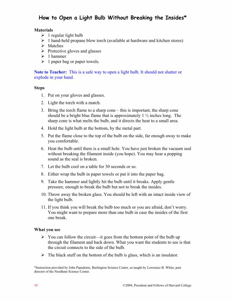
How to Open a Light Bulb Without Breaking the Insides*
48 ©2004, President and Fellows of Harvard College
Materials 1 regular light bulb 1 hand-held propane blow torch (available at hardware and kitchen stores) Matches Protective gloves and glasses 1 hammer 1 paper bag or paper towels.
Note to Teacher: This is a safe way to open a light bulb. It should not shatter or explode in your hand. Steps
1. Put on your gloves and glasses.
2. Light the torch with a match.
3. Bring the torch flame to a sharp cone – this is important, the sharp cone should be a bright blue flame that is approximately 1 ½ inches long. The sharp cone is what melts the bulb, and it directs the heat to a small area.
4. Hold the light bulb at the bottom, by the metal part.
5. Put the flame close to the top of the bulb on the side, far enough away to make you comfortable.
6. Heat the bulb until there is a small hole. You have just broken the vacuum seal without breaking the filament inside (you hope). You may hear a popping sound as the seal is broken.
7. Let the bulb cool on a table for 30 seconds or so.
8. Either wrap the bulb in paper towels or put it into the paper bag.
9. Take the hammer and lightly hit the bulb until it breaks. Apply gentle pressure, enough to break the bulb but not to break the insides.
10. Throw away the broken glass. You should be left with an intact inside view of the light bulb.
11. If you think you will break the bulb too much or you are afraid, don’t worry. You might want to prepare more than one bulb in case the insides of the first one break.
What you see
You can follow the circuit—it goes from the bottom point of the bulb up through the filament and back down. What you want the students to see is that the circuit connects to the side of the bulb.
The black stuff on the bottom of the bulb is glass, which is an insulator.
*Instruction provided by John Papadonis, Burlington Science Center, as taught by Lawrence B. White, past director of the Needham Science Center.
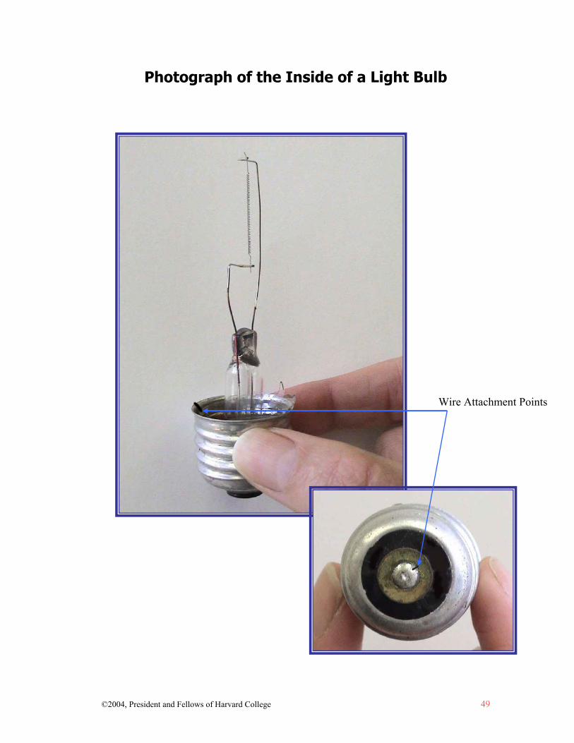
©2004, President and Fellows of Harvard College 49
Photograph of the Inside of a Light Bulb
Wire Attachment Points
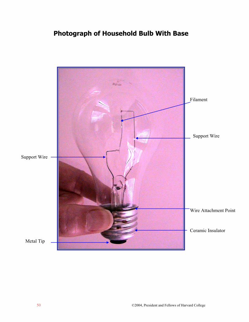
50 ©2004, President and Fellows of Harvard College
Photograph of Household Bulb With Base
Support Wire
Support Wire
Filament
Ceramic Insulator
Metal Tip
Wire Attachment Point

©2004, President and Fellows of Harvard College 51
Diagram of Household Bulb With Base
Filament
Support Wire Support Wire
Metal Tip
Wire Attachment Point
Ceramic Insulator

52 ©2004, President and Fellows of Harvard College
Photograph of Household Bulb Without Base
Support Wire
Support Wire
Filament
Support Wire Support Wire
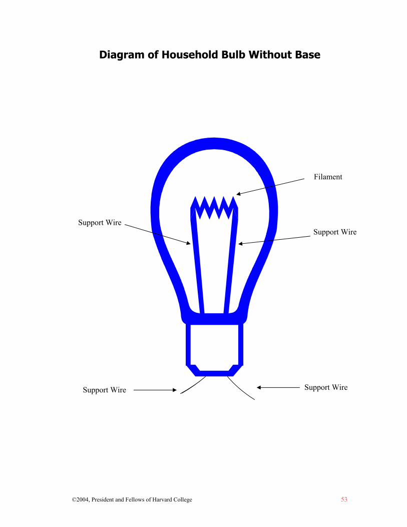
©2004, President and Fellows of Harvard College 53
Diagram of Household Bulb Without Base
Support Wire Support Wire
Filament
Support Wire Support Wire
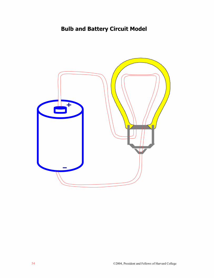
54 ©2004, President and Fellows of Harvard College
Bulb and Battery Circuit Model
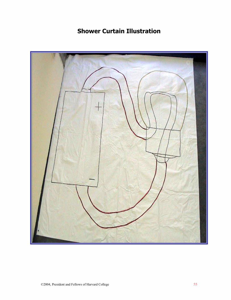
©2004, President and Fellows of Harvard College 55
Shower Curtain Illustration
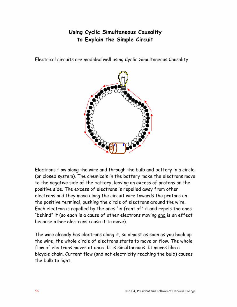
56 ©2004, President and Fellows of Harvard College
Using Cyclic Simultaneous Causality to Explain the Simple Circuit
Electrical circuits are modeled well using Cyclic Simultaneous Causality. Electrons flow along the wire and through the bulb and battery in a circle (or closed system). The chemicals in the battery make the electrons move to the negative side of the battery, leaving an excess of protons on the positive side. The excess of electrons is repelled away from other electrons and they move along the circuit wire towards the protons on the positive terminal, pushing the circle of electrons around the wire. Each electron is repelled by the ones “in front of” it and repels the ones “behind” it (so each is a cause of other electrons moving and is an effect because other electrons cause it to move). The wire already has electrons along it, so almost as soon as you hook up the wire, the whole circle of electrons starts to move or flow. The whole flow of electrons moves at once. It is simultaneous. It moves like a bicycle chain. Current flow (and not electricity reaching the bulb) causes the bulb to light.
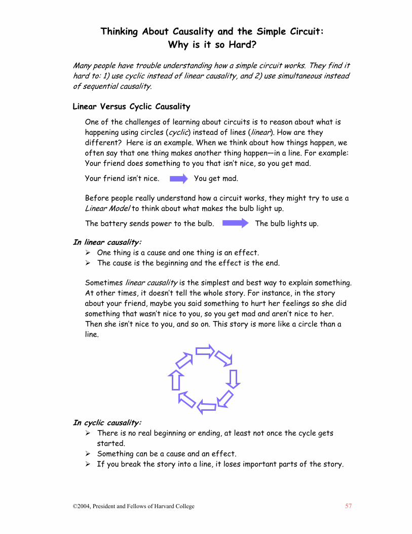
Thinking About Causality and the Simple Circuit: Why is it so Hard?
©2004, President and Fellows of Harvard College 57
Many people have trouble understanding how a simple circuit works. They find it hard to: 1) use cyclic instead of linear causality, and 2) use simultaneous instead of sequential causality. Linear Versus Cyclic Causality
One of the challenges of learning about circuits is to reason about what is happening using circles (cyclic) instead of lines (linear). How are they different? Here is an example. When we think about how things happen, we often say that one thing makes another thing happen—in a line. For example: Your friend does something to you that isn’t nice, so you get mad.
Your friend isn’t nice. You get mad.
Before people really understand how a circuit works, they might try to use a Linear Model to think about what makes the bulb light up.
The battery sends power to the bulb. The bulb lights up. In linear causality:
One thing is a cause and one thing is an effect. The cause is the beginning and the effect is the end.
Sometimes linear causality is the simplest and best way to explain something. At other times, it doesn’t tell the whole story. For instance, in the story about your friend, maybe you said something to hurt her feelings so she did something that wasn’t nice to you, so you get mad and aren’t nice to her. Then she isn’t nice to you, and so on. This story is more like a circle than a line.
In cyclic causality:
There is no real beginning or ending, at least not once the cycle gets started.
Something can be a cause and an effect. If you break the story into a line, it loses important parts of the story.
58 ©2004, President and Fellows of Harvard College
Sequential Versus Simultaneous Causality
A second challenge of learning about circuits is to reason about what is happening by thinking about it all at once (simultaneous) instead of step-by-step (sequential). How are these approaches different? Here is an example. When we think about how things happen, we often use steps even when it is not how things work. For example, the hands of a clock all move at once, but we might break it down into the following steps:
1. The second hand moves. 2. Then, the minute hand moves. 3. Then, the hour hand moves.
Before people really understand how a circuit works, they might use sequential causality to think about what causes current flow.
1. Electrons crowd onto the wire. 2. Then, they move to where the bulb is. 3. Then, they light the bulb. 4. Then, they continue through the wire to the battery. 5. Then, they make the trip again.
In sequential causality:
Things happen step by step or in order. There is a pattern that unfolds over time. Causes occur before effects.
However, some events are not sequential. They can be simultaneous. This means that they happen all at once. For example, the clock hands really all turn at once. We just break it down into steps to make it easier to think about. Circuits are also like that. Electrons repel the ones “ahead” of them while being repelled by the ones “behind” them. It happens all at once and the current flows or moves the way that a bicycle chain moves.
In simultaneous causality:
Things happen all at once. There is a pattern that unfolds over time. Causes and effects happen at the same time.
Simultaneous causality is hard to understand because causes and effects can happen at the same time. We usually expect causes to come before effects. Simultaneous causality is also hard to talk about because if you break it up into steps to tell the story of what happens, you lose the idea that it all happens at once.

©2004, President and Fellows of Harvard College 59
LESSON 3: WHAT ARE CONDUCTORS AND
INSULATORS? This lesson introduces conduction and insulation to prepare students to
think about resistance and why the filament in a light bulb behaves differently than the copper conduction wires. The lesson invites students to explore a variety of materials to determine their level of conductivity. There are versions of this lesson in most elementary science programs.
Additional Resources for Lesson 3 Predicting Conductors and Insulators sheet

©2004, President and Fellows of Harvard College 61
Lesson 3: What are Conductors and Insulators?
Understanding Goals Subject Matter
Some materials allow electrons to move more freely along them than others. This has to do with the nature of their bonds.
Materials that allow electrons to move freely are called conductors. Materials that do not allow electrons to move easily are called insulators.
Causality Material types affect current flow, comprising a form of passive causality.
Background What Makes a Good Conductor or Insulator?
The nature of the bonds at the atomic level of a material determines whether or not it is a good conductor. Some materials are bonded so that the electrons in their outer shells are very stable. This is true for materials that are ionically or covalently bonded. These do not make good conductors. Instead, they are good insulators. Materials that have metallic bonds have electrons that are free to move about in an electron cloud (not associated with any atom in particular.) These make good conductors. This lesson invites students to experiment with different materials to see which work as conductors and which do not. Students keep a record of their findings so that they can compare the types of materials that work as conductors and those that work as insulators. A Passive Causal Variable
Often when we think about causality, we think about agent-oriented causality, where there is a clear actor in a causal relationship—such as electrons causing flow in the circuit. It can be harder to realize the role of variables that are, in some sense, passive. However, as the testing of materials in this lesson indicates, the type of material plays an important role in current flow. Material type is a variable that plays a passive causal role in relation to conduction and insulation. It is analogous to the role that structures like train tracks and bridges play in travel. These things aren’t active in their role, but they are critical to the outcome. This lesson alerts students to the fact that the type of material plays a role in current flow.

Causal Patterns in Simple Circuits: What are Conductors and Insulators?
62 ©2004, President and Fellows of Harvard College
Lesson Plan Materials
“D” cell battery, 1 per pair of students Wire, (insulated copper wire with plastic coating, apx. 6 inches long with
copper ends exposed), 3 per pair of students Flashlight bulbs, 1 per pair of students Bulb holders, 1 per pair of students Battery holders, 1 per pair of students Re-sealable plastic bag for insulation/conduction test. 1 bag per pair of
students filled with the following items: o Toothpick o 1" piece of straw o Paper clip o 1" x 1" piece of aluminum foil o Wooden pencil stub sharpened at both ends o Marble o Piece of paper o 1" piece of chalk o Brass paper fastener o Penny, dime, nickel, and quarter o 1" x 1" piece of plastic screen o 1" x 1" piece of aluminum screen o Styrofoam peanut
Prep Step
Review the lesson plan, background information, and understanding goals. Gather items for the insulation/conduction test. Create a set of testing materials for each pair of students by bagging together
each of the items. Photocopy the sheets, Predicting Conductors and Insulators (pp. 64-66), 1 per
pair of students.
Analyze Thinking Step 1: Revealing Current Thinking
Ask, “Do all things let electrical current flow move along them?” Another way to ask the question is, “Do all things allow their electrons to move easily?” Have each student record some thoughts in their journal and give examples before opening up group discussion. So far, we have mostly talked about the role of active causes in how a circuit works, such as electrons that move. However, as this lesson will show, some variables are part of the causal story but are passive causes.

Causal Patterns in Simple Circuits: What are Conductors and Insulators?
©2004, President and Fellows of Harvard College 63
Example of a Tester
Have students share their ideas. The activity that they do in this lesson will either support or challenge their current ideas.
RECAST Thinking Step 2: Testing Whether Different Materials Affect Current Flow
Have students work in pairs to experiment with a variety of materials to discover their level of conductivity. (For this lesson, students group the materials as conductors or insulators, but in the next lesson we’ll begin to talk about conduction on a continuum.) Pass out the sheets, Predicting Conductors and Insulators (pp. 64-66), and the bags filled with testing materials to each pair of students. They will record their findings on the handout, or they can set up a recording sheet in their journals.
Demonstrate to the class how to set up a tester. Explain that in this activity, they will be using a bulb holder and a battery holder. The holders don’t do anything besides help to hold the wires in the right places so that the students don’t have to. (As they saw in earlier lessons, you don’t have to have a bulb holder or a battery holder to make the bulb light.) The tester should have one wire coming from each end of the battery. One of those wires should go directly to the bulb holder. A third wire should extend from the bulb holder. When they test an item, they will hold it between the two wires with free ends (one coming from the battery holder and one coming from the bulb holder). In order to make sure that they have set their tester up correctly, they should test it by touching the two loose wire ends together to make sure that the bulb lights.

Causal Patterns in Simple Circuits: What are Conductors and Insulators?
64 ©2004, President and Fellows of Harvard College
Students should work through the objects systematically. For each one, they should first predict what they think will happen and record their prediction on the recording sheet. Then they should check the conductivity of each material by placing it between the ends of two wires as part of a circuit to try to light the bulb. They should record their finding on their recording sheet.
Step 3: Making Generalizations
Afterwards, have students summarize what they found out. Review each of the materials on their list. Students will have noticed that in some cases the bulb lit and in some cases it didn’t. When it did light, it was brighter with some materials than with others.
Some materials are more conductive than others. We call these conductors. Materials that are not very conductive are called insulators. Explain that this has to do with how the material is bonded and how easily electrons can move within it.
Explore Causality Step 4: Introducing Passive Causality
Often, when we think about causality, we think about cases where there is a clear agent in a causal relationship, such as the electrons. It can be harder to realize the role of variables that are, in some sense, passive. The variable of material type
Checking the Conductivity of the Testing Materials

Causal Patterns in Simple Circuits: What are Conductors and Insulators?
©2004, President and Fellows of Harvard College 65
plays a passive causal role in relation to conduction and insulation. However, as the testing of materials above indicates, the type of material plays an important role in current flow. Here is an analogy. We think of a train as the way that we get places, but in order to get somewhere we also need train tracks, bridges to get across rivers, etc. These things aren’t active in their role, but they are critical to the outcome.
Review, Extend, Apply Step 5: Making Connections
Ask: • If only some materials conduct electricity, why is it possible for humans to
get a shock? See what your students think. Our bodies contain a lot of water and salt. These substances are very conductive.
• If only some materials are conductors, how could lightning hitting telephone wires result in you getting a shock from your plastic telephone? Discuss how the amount of force behind the electrons makes a difference. With enough voltage, even the most tightly bonded electrons can be made to move. Voltage is the amount of push that the electrons “behind” any given electron can deliver. This means that anything, even things that we call insulators, can conduct electricity if there is enough force. However, it is also the case that electrons tend to move down the “easiest” or most conductive path when there is one for them to go to. That is why lightning, which has extremely high voltage, choose certain paths over others. The electrons will take the path of least resistance.
In order to prepare for the next lesson, ask students to take a look around their homes for different types of bulbs. Have them try to find a few different kinds and see if they can see what each looks like inside. They should make a quick sketch of each type they find. Warning: Tell students not to touch the bulbs that they find around their homes while lit. If they want to take them out of a lamp, they must unplug it first and put the bulb back in before they plug it in. Also, they need to be careful not to break the glass of the bulb.
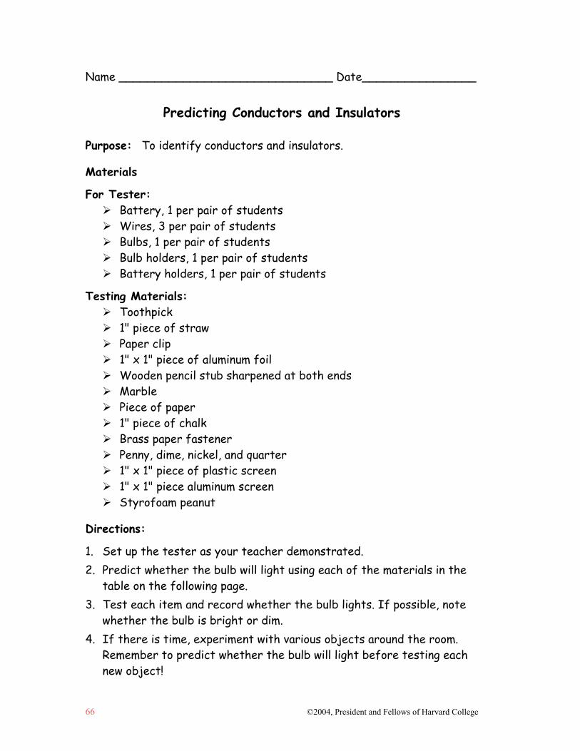
66 ©2004, President and Fellows of Harvard College
Name ______________________________ Date________________
Predicting Conductors and Insulators Purpose: To identify conductors and insulators.
Materials
For Tester: Battery, 1 per pair of students Wires, 3 per pair of students Bulbs, 1 per pair of students Bulb holders, 1 per pair of students Battery holders, 1 per pair of students
Testing Materials: Toothpick 1" piece of straw Paper clip 1" x 1" piece of aluminum foil Wooden pencil stub sharpened at both ends Marble Piece of paper 1" piece of chalk Brass paper fastener Penny, dime, nickel, and quarter 1" x 1" piece of plastic screen 1" x 1" piece aluminum screen Styrofoam peanut
Directions:
1. Set up the tester as your teacher demonstrated. 2. Predict whether the bulb will light using each of the materials in the
table on the following page. 3. Test each item and record whether the bulb lights. If possible, note
whether the bulb is bright or dim. 4. If there is time, experiment with various objects around the room.
Remember to predict whether the bulb will light before testing each new object!

©2004, President and Fellows of Harvard College 67
Results Item Predictions: Will the bulb be on
or off? Why do you think this will happen?
Actual Results
Toothpick
Straw
Paper clip
Aluminum foil
Pencil stub
Marble
Paper
Chalk
Brass paper fastener
Penny
Dime
Nickel
Quarter
Plastic screen
Aluminum screen
Styrofoam peanut
68 ©2004, President and Fellows of Harvard College
Conclusion 1. In your own words, what is a conductor? 2. In your own words, what is an insulator? 3. If you were to test the different parts of the bulb (base, glass, etc.)
what parts would be conductors? What parts would be insulators? What about the glass itself?
©2004, President and Fellows of Harvard College 69
LESSON 4: WHY DOES THE BULB LIGHT WHEN
THERE IS FLOW?
This lesson engages students in thinking about resistance as a passive type of causality, and helps them to view resistance on a continuum between
conductivity and insulation. There are similar lessons in many science programs to help students learn about the nature of resistance. However, this one is modified to offer systematic inquiry into variables that affect resistance
and to help students understand the passive causality involved.
Additional Resources for Lesson 4 What Contributes to a Good Filament?: Testing Variables sheet
Diagram of a Circuit Tester Photograph of a Circuit Tester

©2004, President and Fellows of Harvard College 71
Lesson 4: Why Does the Bulb Light When There is Flow?
Understanding Goals Subject Matter
On the continuum of insulators and conductors, some materials are “in between.” With enough “push,” or voltage, the electrons in a material flow along it, but it is difficult for them to do so.
These materials are called resistors. Resistance can be thought of as an impediment to the flow of the current.
Causality
Resistors are passive causal agents. For instance, a resistor passively causes a bulb in a circuit to light by making the path of the current more difficult. Because resistors are passive, people sometimes forget to think about them when assembling the causal story of a simple circuit.
Background Information Developing a Mental Model of Resistance
The purpose of this lesson is to help students develop a mental model of how resistance affects a circuit and to understand what variables contribute to resistance. Resistance is an impediment to the flow of electrical current. The electrons in the filament of the bulb are jostled and move very vigorously, but their movement is random and therefore it inhibits forward flow. With enough “push” or voltage, electrons do flow through the filament material, but due to all the random movement, they heat up, and this heat gives off light. Students often forget to think about resistance when conceptualizing a simple circuit because the role of resistance is passive. While a filament’s resistance impedes current flow and is the reason the bulb lights, most learners focus on the active role of electrons in making the bulb light. However, it is important not to use language that tries to make the passive effect active. For instance, some teachers talk about resistance as a push in the opposite direction. One problem with this is that it could lead students to incorrectly think that the push is there when there is no current flow. Instead, help students focus on resistance as an impediment to flow. Students also tend to think of resistance as slowing down the current. Many analogies inadvertently support this “speed” notion. This can lead to confusions. For instance, the more particles heat up, the faster—or better put, more vigorously—they move. However,
Causal Patterns in Simple Circuits: Why Does the Bulb Light When There is Flow?
72 ©2004, President and Fellows of Harvard College
faster or more vigorously moving particles result in greater impediment to flow. For these reasons and others, it is important to get students to focus on the impediment as limiting the amount of current that can flow rather than the mistaken idea that it has to do with speed of flow. Some Variables that Contribute to Resistance
The variables of material type, diameter, and the temperature of the filament wire all contribute to the amount of resistance. These variables work to create an impediment to the flow of electrons, thereby affecting the current in the circuit.
• The type of material of the filament wire. The type of material affects the amount of resistance, as described in the previous lesson. In an insulator, nearly all of the electrons are tightly held by individual atoms or are shared by pairs of atoms. Since no electrons are free to move from atom to atom, insulators do not conduct electricity. In a conductor, one or two electrons from each atom are free to move from atom to atom. The movement of these free electrons from areas of higher electron concentration to areas of lower electron concentration is what we call current.
Some materials, like Nichrome, include both free electrons and electrons that are tightly held in covalent bonds. The electrons in the covalent bonds repel the free electrons and act as obstacles to the movement of the free electrons. As the free electrons move through the material they bump into the electrons and atoms in the covalent bonds. This makes it more difficult for electrical current to flow and all the jostling causes the material to heat up. Materials like Nichrome are said to have higher resistance than better conductors like pure copper. Even good conductors include minor obstacles to the movement of free electrons, which is why even a good conductor will heat up when a large current passes through it.
• The diameter (width or thickness) of the filament wire. The diameter of the
wire also affects the amount of resistance. The conductivity of the wire is proportional to the area of the cross-section. This means that the more cross-sectional area a wire has, the more easily it will conduct the forward flow of electrons; and the less cross-sectional area it has, the more it will resist the forward flow of electrons. So as diameter (and cross-sectional area) is increased or decreased, a change takes place. (For example, compare two wires, one with a 1 inch diameter and one with a 2 inch diameter. The 2 inch wire actually has four times the cross-sectional area of the 1 inch wire. For round wires, the cross-sectional area is proportional to the square of the radius.) A way to envision it (see p. 77) is to think of a pipe and imagine that it is square instead of round. Draw a square that is 1 inch on each side and then expand it to a square that is 2 inches on each side. You will see that the area of the 2 inch pipe (and therefore the flow that it can carry) is 4 times that of the 1inch pipe. The 1 inch square pipe fits in 1/4 of the 2 inch square pipe.
Causal Patterns in Simple Circuits: Why Does the Bulb Light When There is Flow?
©2004, President and Fellows of Harvard College 73
• The temperature of the filament wire. The temperature of the wire also matters. As electrons flow throughout the wires when the circuit is complete, all the atoms in the wire become more energetic. This excited state of the atoms is reflected in a higher temperature (that is, temperature is a measure of a higher energy state). The resistance materials increase as the temperature increases. For instance, when current flows through the filament, it gets hotter, which means that it becomes increasingly thermally energetic, making it harder for current to flow. Think of it this way: heat is kinetic energy. This means that the hotter something is, the more vigorously its atoms are moving. The greater the random motion of the atoms (and of the electrons as part of atoms), the harder it is to sustain the flow, because as electrons move forward, they collide with other fast moving atoms and get knocked around. Eventually the filament gets so hot that it glows white.
Note to Teacher: In the process of experimentation, students may discover that the length of the filament wire also matters. If students use a ½ inch length of #32 Nichrome wire, it will glow. If they use a 1 inch length of #32 Nichrome wire, it will not. This is hard to explain without understanding a potential difference model and attending to the circuit as an entire system. This lesson does not attempt to explain filament length.
The important contribution of resistance to current flow can be seen when one creates a short circuit. A short circuit (i.e. a battery and a wire, but no bulb) has no resistors or devices that add significant resistance into the circuit. Therefore, there is nothing to minimize the amount of current, and the wires heat up very quickly. This can be counter-intuitive. Above we said that increased resistance (in the filament) results in heat. Here, the opposite case is being made. How can both be true? They heat up for slightly different reasons. Whereas the filament heats up because of the random bouncing around of electrons and the resistance to forward flow, the circuit wires in a short circuit heat up because there is nothing to minimize the amount of flow. The more atoms that pass through a given area, the more jostling and bouncing that can occur—this movement is kinetic energy, or heat energy.
The Challenge of Isolating the Role of the Filament
The explanation of the filament that follows offers information that is beyond the scope of what this module covers, but addresses some puzzles that could arise for students. It is offered here for teachers as background, but is not needed for the lesson. Like most science concepts, as soon as you delve deeply into electricity/electrical circuits, the concepts become complex. This lesson introduces the concept of
Causal Patterns in Simple Circuits: Why Does the Bulb Light When There is Flow?
74 ©2004, President and Fellows of Harvard College
resistance at a level that students should be able to grasp given the background provided thus far. However, a deep understanding of why filaments glow requires students to reason about the circuit as a complex system. As students begin to deeply probe the model presented here, they may discover some puzzles. This is because it isn’t strictly possible to examine just the filament wire without attending to the entire system. You can’t actually isolate the role of the filament in the circuit. However, students also need to develop some understanding of how the filament acts as a limiting factor in the broader system. The resolution to these puzzles engages students in complex concepts that are beyond the scope of this module. However, the issues are elaborated further here for those teachers who would like to understand it for background information or would like to consider presenting aspects of the ideas to their students. The experiments in this lesson are designed to help students understand the variables involved in resistance. However, it is important for teachers to realize that the experiment is actually an imperfect one in a couple of ways. The primary reason is that a battery is an imperfect voltage source. In the case of a circuit with a copper filament wire, the wire’s resistance is so low that the battery, and not the wire, limits the rate of current flow. Electrons can flow from the negative terminal to the positive terminal through the wire faster than the chemical reactions in the battery can move the charge. The battery cannot maintain the full level of electrical imbalance (voltage difference) between the terminals. As a result the current through the wire drops until it matches the rate at which the battery can move charge internally. If you measure the voltage between the terminals of the battery when you do the filament experiments, you will find a much lower voltage than 1.5V (the voltage of the batteries used here and in most classroom experiments) while the current flows. By contrast, the Nichrome filament wire glows because it has enough resistance to be the rate-limiting factor in the system, meaning that the battery maintains a full 1.5V difference between the terminals. The greater potential difference distributed through the Nichrome wire means electrons flow more energetically through the wire than they do through copper, thus jostling the atoms of the Nichrome more vigorously. Because of the different voltages, the comparison between the copper and Nichrome wires is not completely parallel. Some classrooms use a rheostat, a device that enables the teacher to adjust the amount of voltage coming out of outlets in the science lab. This makes it possible to make a more direct comparison. However, we DO NOT recommend this. Students can easily forget that the voltage has been adjusted to be different from that in their home and might engage in unsafe behavior with electrical outlets at home. While the lesson introduces three contributing variables (material type, diameter and temperature of the filament wire) the story of how a light bulb lights is actually quite complex—more complex than students will readily be able to reason about or are asked to in this module. Therefore, they may discover puzzles when trying to apply
Causal Patterns in Simple Circuits: Why Does the Bulb Light When There is Flow?
©2004, President and Fellows of Harvard College 75
the three variables. For instance, students might notice that electrical bulbs have different brightness levels.1 They might also notice that bulbs with high intensity also have filaments that are thicker and low resistance, and bulbs with low intensity have filaments that are thinner and high resistance. This appears to contradict what was learned in the lesson. The contradiction can be resolved, but it quickly engages students in a complex systems problem beyond the scope of this module. In order to resolve these problems that may arise, one needs to reason about the system at the level of the entire circuit and about how factors interact in complex ways. For instance, one needs to include factors such as the ability of the battery to maintain voltage and the internal resistance of the battery itself. One also needs to reason about the complex balance involved in the variables related to the filament. The trick to creating a filament, or having a wire work as a filament, is to move enough current through the circuit but also to have enough resistance to convert the energy to heat and ultimately light energy. (So in choosing a filament, a balance needs to be struck between allowing enough energy in (in terms of current flow), but creating enough resistance to convert that energy to light to give the brightest or most intense light. In this case, the most current is allowed to flow, but the filament creates enough resistance to get the most voltage drop.) So the balance between enough current flow and enough resistance to convert that energy to light energy (as opposed to just heat2) is a tricky one. This is all cognitively complex enough, yet in order to reason about what is happening, one needs to think about the components of the circuit as a system—connected and impacting one another. The “bicycle chain of electrons” cannot move at more than the rate of the most limiting component. As Ohm’s Law (the focus of Lesson 8) explains, the amount of current (flow) in a circuit depends upon voltage (push) and resistance (impediment).
1 The physics term that is used to specify brightness is power. That is the amount of energy generated
by the bulb each second and is measured in watts. A 100 watt bulb generates 100 joules (energy or work) each second.
2 A wire can have a lot of current flowing along it and give off heat energy but not necessarily light
energy. If a voltage differential between the two ends of a wire filament is maintained, the wire with the least resistance would generate the most heat (as in a short circuit). This wire would not necessarily glow the brightest, though, because the power achieved depends upon the relative rate of flow of thermal energy in AND out of the wire (Power = Current x Voltage Drop) and while this wire would have the greater thermal energy flow in, greater surface area means that it would also have a higher rate of heat flow out.
Causal Patterns in Simple Circuits: Why Does the Bulb Light When There is Flow?
76 ©2004, President and Fellows of Harvard College
Lesson Plan Materials
“D” cell battery, 2 per pair of students Wire, (insulated copper wire with plastic coating, apx. 6 inches long with
copper ends exposed), 3 per pair of students Lumps of clay or play dough, 1-2 lumps per pair of students Re-sealable plastic bags, 1 per pair of students, with the following items:
o 2 inch piece of #26 and #32 Nichrome wire o 2 inch piece of #32 steel wire
What Contributes to a Good Filament?: Testing Variables sheet, 1 per pair of students
For resistance demonstration: o Marbles, apx. 100 white and 100 black o Clear plastic tubing filled with marbles from Lesson 3, approximately 3
feet long, 1 ½ inches in diameter o Small plastic tubing that is approximately half of the circumference of the
larger tube. o One set of objects that were tested in Lesson 3 (p. 60).
Prep Step
Review the lesson plan, background information, and understanding goals. Collect materials and put 2 inch piece of #26 and #32 Nichrome wire, and 2
inch piece of #32 steel wire in a re-sealable plastic bag. (Nichrome and steel wires can be purchased at a hardware store; however, they may be difficult to find. Plan ahead as you may need to go to a specialty hardware store to buy these.)
Photocopy What Contributes to a Good Filament?: Testing Variables sheet (p. 79), 1 sheet for each pair of students
Analyze Thinking Step 1: Analyzing Initial Thinking about the Filament
Ask students to think about what is in a light bulb. This is a review from Lesson 2. What do they think is going on along the filament that causes the light bulb to light? Have them draw a model of their ideas. You may see some of the ideas explained in the introduction (where protons and electrons clash or attract and so forth).
Explore Outcomes Step 2: Creating Filaments
Explain to your students that they are going to create filaments in class today. Students should work in pairs. Demonstrate how to build a circuit for testing the

Causal Patterns in Simple Circuits: Why Does the Bulb Light When There is Flow?
©2004, President and Fellows of Harvard College 77
filaments. The graphic and photograph on pages 80 and 81 illustrate how the circuit should look. The students will use lumps of clay or play dough to secure the wires in an upright position. Pass out the sheet, What Contributes to a Good Filament?: Testing Variables. Students should make the comparisons in steps 1-3 below to see what happens when they hook up a wire as a filament.
IMPORTANT SAFETY INSTRUCTIONS
• When hooking up the filament wire, you MUST disconnect the battery first. The wire can get very hot, and touching it when it is hooked up could result in a burn. Reconnect the battery after the filament wire is in place.
• When disconnecting the filament wire, first disconnect the battery, wait for the wire to cool, and then remove it.
• DO NOT touch the wire to test it if it looks like it isn't doing anything. It could be hot. Instead put your hand near the wire to see if you feel heat.
• Handle the wires carefully. Some of the wires are thin and it is possible to get pricked or cut by them.
Students should work step-by-step exploring answers to the following questions:
1. Does the thickness (width or diameter) of the filament wire matter?
Have students first wrap a 2 inch length of #26 of Nichrome wire between the two supporting wires and test it with the battery. Then, have them wrap a 2 inch length of #32 wire and compare. Explain that #26 is actually thicker than #32. Discuss findings.
2. Does the type of material of the filament wire matter? Have students compare a 2 inch length of Nichrome wire to a 2 inch length of steel wire of the same thickness (#32 Steel to #32 Nichrome). Discuss findings.
3. Does the temperature of the filament wire matter? When students first hooked up any of the wires, did the effects happen immediately, or did it take a while to notice the effects? Did the effects appear to increase as the wire got hotter?
Step 3: Thinking About Resistance
After the students have had a chance to test each variable, gather them together as a group and review their results. They should have found that the #32 Nichrome wire glows a bright red and that it takes a few seconds to turn bright red. The #26 wire gets hot and appears a little white. The steel wire warms up some but the least of all.
Causal Patterns in Simple Circuits: Why Does the Bulb Light When There is Flow?
78 ©2004, President and Fellows of Harvard College
Discuss what is happening using the Cyclic Simultaneous Model to think about the circuit. Use the shower curtain model and the plastic tubing model as part of the discussion, or draw the concepts on the board. Remind students that the circuit has electrons all along it. Review the idea that the electrons are all moving at once like a bicycle chain. Focus on the filament. Point out that the filament is very hard to get through and this makes it harder for the electrons to flow. We call this resistance. Resistance is measured in ohms. Try to stay away from the idea of resistance as having to do with speed. It really has to do with the possibility of pushing electrons along the filament and the difficulty of doing so.
Give students an analogy to help them think about what is going on, such as; “Think about how it feels when you run along a beach. Now think about how it feels when you run in the water. Which one feels harder?" Nichrome wire is like "running in the water" for electrons, and copper wire is like "running on the beach" for electrons. There is more resistance to movement through water than through air. Illustrate each of the variables that determine how easy it is for electrons to move along the filament.
• The thickness (width or diameter) of the filament wire: Show your students the wide tubing with marbles in it. Next, show the small piece of tubing that represents the filament. Electrons have a harder time moving through the narrower wire than the wider wire, so forward flow is impeded. Draw a 2 inch square on board. Then draw a 1inch square that fits in one corner. The #32 Nichrome wire is much smaller that the #26 Nichrome wire. (Remind the students that the larger number goes with the thinner wire.) This shows that the smaller wire (though not hollow) makes the flow harder because there are not as many atoms available (i.e. electrons to flow). Make sure students understand that while the pipe and the tubing in the analogies allow things to flow within them, a wire allows things to flow along it. The electrons that make up the wire are moving.

Causal Patterns in Simple Circuits: Why Does the Bulb Light When There is Flow?
©2004, President and Fellows of Harvard College 79
Comparison of Conductivity of Material in Relation to Size:
Square Pipe Example
• The type of material of the filament wire: Discuss the concept of insulators
and conductors on a continuum. In an insulator, there is not much opportunity for electrons to move. In a conductor, there are many opportunities for electrons to move, allowing the current to flow easily. Explain that the Nichrome wire is somewhere in between. Because of the way that the atoms are bonded, there are places where electrons cannot move, and these places become obstacles to the overall flow of electrons. Electrons can move along the wire, but it is very difficult. Impeding the flow of electrons results in an energy transfer (the electrons bounce all around instead of moving forward, further impeding flow) that heats the fine wire, which becomes hot enough to glow and give off light. Show students some materials along the rough scale of conductors to insulators (from their experimentation in the last lesson).
Ask, "Where would we put these materials on the scale?"
Copper wire Aluminum foil Nichrome wire Plastic straw
Good Conductors Good Insulators
Make sure that students realize that the circuit wire has less resistance than the filament wire. The circuit wire is typically made of copper. Resistance is an impediment to the flow of electrons. The resulting amount of current throughout the entire circuit depends upon the amount of resistance in the circuit.
2 inch pipe Size and flow rate of 1 inch pipe compared to 2 inch pipe
1 inch pipe
Causal Patterns in Simple Circuits: Why Does the Bulb Light When There is Flow?
80 ©2004, President and Fellows of Harvard College
• The temperature of the filament wire: The hotter the wire gets, the more the electrons bounce all around, raising the temperature and giving off heat and light energy. With an increase in how much the electrons are bouncing around, resistance increases. Imagine trying to move in a forward direction in a crowd where everyone is bouncing back and forth in random directions. It would be pretty tough to maintain your forward path!
Explore Causality Step 4: Reflecting on Passive Causality
Explain to the students that when we think about a circuit, it is easy to forget about resistance. The role of the electrons is easier to think about because they are doing something active—they are agents! But resistance is a very important part of what determines the amount of current flowing in the circuit. Later lessons will further address the role of resistance. Passive causality can be understood by thinking of other variables or structures that somehow cause an effect but do not actively “do” anything. For instance, a high fence keeps people out of certain places and a bridge allows people to cross a river, but neither a fence nor a bridge is moving or active.
Pose the following question:
“Some students want to talk about resistance as a push in the opposite direction. Do you think that this is a good idea or not?” Gather students’ thoughts. A problem with this is that it could lead students to incorrectly think that the push is there when there is no current flow. Instead, it helps to focus on resistance as an impediment to flow.
Review, Extend, Apply Step 5: Making Connections: Explaining a Short Circuit
Now that students have thought more about resistance, ask them how they would explain a short circuit. What’s going on? Students should realize that a lot of current moves through the circuit because there is nothing to make it more difficult for electrons to move.
Step 6: Making Connections: Blowing a Bulb
Show what happens when you burn out a bulb by using too high a voltage. You can see material from the filament wire splattered across the inside of the bulb. Metal atoms that make up the filament are now inside the glass bulb. The very high current created so much heat in the filament that the metal vaporized. Atoms got jostled so hard that they literally blew apart! Even though there was resistance, the voltage was so great that the electrons really moved, overheating the filament.

©2004, President and Fellows of Harvard College 81
Name Date What Contributes to a Good Filament?: Testing Variables
Record the results from testing filaments below:
Type of Material
Thickness of Wire
Result after 3 seconds?
Result after 10 seconds?
Nichrome
#26 (thicker)
Nichrome
#32 (thinner)
Steel
#32
Summarize your findings about filaments:
1. Which of the variables above make a difference in whether or not the filament lights?
2. What do you think is going on? 3. Write down any ideas that you have that could explain why the
filament glowed in some instances but not in others.

82 ©2004, President and Fellows of Harvard College
Diagram of a Circuit Tester
Alternately, # 26 Nichrome Wire # 32 Nichrome Wire # 32 Steel Wire
Hook-up wire
Clay or Play Dough
Batteries in Battery Holders

©2004, President and Fellows of Harvard College 83
Photograph of a Circuit Tester


©2004, President and Fellows of Harvard College 85
LESSON 5: WHAT HAPPENS WHEN BULBS OR
BATTERIES ARE IN SERIES OR PARALLEL?
This lesson engages students in experimenting with series and parallel circuits and asks them to model what they think is going on and why.
It asks students to record and compare their results and to begin thinking about why the differences exist between the different types of circuits.
Additional Resources for Lesson 5 Predictions on Parallel and Series Circuits sheet
Student Examples: Predictions on Parallel and Series Circuits Investigating Series and Parallel Circuits sheet
Student Example: Investigating Series and Parallel Circuits

©2004, President and Fellows of Harvard College 87
Lesson 5: What Happens When Bulbs or Batteries are in Series or Parallel?
Understanding Goals Subject Matter
When you arrange two bulbs in series, they will shine less brightly than if there was one bulb, and less brightly than if they are arranged in parallel. Both bulbs have equal brightness.
Two bulbs arranged in parallel shine as brightly as when there is only one bulb. (However, if you keep adding bulbs in parallel until there are many bulbs, eventually they will all get dimmer.)
Arranging batteries in series increases the amount of voltage in the circuit. Arranging batteries in parallel results in the same amount of voltage in the
circuit but there is more (battery) chemical available, so the batteries are able to last longer and will be able to maintain their voltage (differential) when higher current flows in the circuit. The bulbs will be the same brightness as they were before the additional batteries were added.
Causality
Students could analyze series and parallel circuits using any of the causal models previously discussed, and find ways to explain the results. However, their explanations would differ from scientifically accepted explanations.
The Cyclic Simultaneous Model is a good intermediate model for explaining what happens in series and parallel circuits. It pushes us to view the circuit as a system instead of as isolated parts.
Background Information The Basics of Series and Parallel Circuits
Series and parallel circuits are some of the most commonly taught concepts in units on electrical circuits. Understanding the differences between them is not always easy. In a series circuit, two or more bulbs are connected in a line, or a series. The wire from the negative contact of the battery goes to a bulb, and a wire from that bulb goes to another bulb and so on, until the wire coming from the last bulb in the series goes back to the positive contact of the battery. When current in the circuit flows, it passes through each of the bulbs directly. In the case of a series circuit with two bulbs, each
Causal Patterns in Simple Circuits: What happens When Bulbs or Batteries are in Series or Parallel?
88 ©2004, President and Fellows of Harvard College
bulb is directly connected to one node of the battery, but not the other node; the pathway from the bulb to the second node has to go through the other bulb. Two bulbs provide more resistance in the circuit than one, so given a standard voltage, the current flowing in a two-bulb series circuit is less than the current flowing in a single-bulb circuit. In a parallel circuit, two or more bulbs are both connected directly to the same battery. So typically more than one wire leaves the negative contact of the battery1
and each wire is connected to a bulb. The wires coming from the bulbs typically each attach back to the positive contact of the battery. Parallel circuits characteristically have branches or splits in the circuit, and are sometimes difficult to identify, because the bulbs may seem to be connected to each other in a series-like way with wires. In order to decide if a bulb is in a parallel circuit, see if you can trace a line from each node of the battery directly to each bulb without passing through another bulb. If so, the circuit is a parallel circuit. The resistance of a bulb is a physical property and doesn't change regardless of what type of circuit it is in. In a two-bulb parallel circuit, each bulb has the same individual resistance as it did in the series circuit. However, the resistance of the entire parallel circuit is less than the resistance of a series circuit because the current has multiple pathways through a parallel circuit. It can be difficult for students to think about resistance in the individual bulbs and in the entire circuit at the same time—in fact, it can be hard to understand why the two are different at all. A "cars on the highway" analogy may help explain the distinction: think of a wide highway narrowing to a one-lane bridge to cross a river. Now imagine that in order to get rid of traffic jams, the highway department builds another one-lane bridge over the river. The "resistance" (in this case analogous to the width), of both bridges stays the same, but the amount of "current" or traffic that can cross the river has increased, so the overall "resistance" of the entire system has decreased.2 In a parallel circuit, the brightness of the bulbs does not change with the addition of more bulbs, but if you added many parallel circuits, eventually all of the bulbs would dim down as you approached the capacity of the battery.
1 There can also be a split after the wire leaves the battery. 2 Mathematically, the relationship of the resistances of individual bulbs in a circuit and the overall
resistance of the entire circuit is very different for series and parallel circuits. In a series circuit, the overall resistance of the entire circuit is the sum of the resistances of each bulb in the circuit. In a parallel circuit, the overall resistance of the entire circuit is the sum of the reciprocals of the resistances of each bulb in the circuit. For a two-bulb circuit, where R1 and R2 are the resistances of the two bulbs, the resistance in the entire circuit is: Series: Rtotal = R1 + R2 Parallel: Rtotal = 1/R1 + 1/R2

Causal Patterns in Simple Circuits: What happens When Bulbs or Batteries are in Series or Parallel?
©2004, President and Fellows of Harvard College 89
Some Configurations of Series and Parallel Circuits
Series Circuit (Bulbs in series)
Parallel Circuit (Bulbs in parallel)
Series Circuit (Batteries in series)
Parallel Circuit (Batteries in parallel)

Causal Patterns in Simple Circuits: What happens When Bulbs or Batteries are in Series or Parallel?
90 ©2004, President and Fellows of Harvard College
Wire
This lesson also introduces what happens when batteries are in series or in parallel. Arranging batteries in series increases the amount of voltage so bulbs will appear brighter. Arranging the batteries in parallel results in the same amount of voltage, but there is more (battery) material available so that the batteries are able to last longer and will be able to maintain their voltage (differential) when there is a higher flow of current. The bulbs in the circuit will be the same brightness as they were before adding additional batteries. Students’ Intuitive Models of Parallel and Series Circuits Teachers commonly ask students to hook up series and parallel circuits and to see what happens. However, this experimentation does not necessarily lead students to formulate new models of the circuit. In fact, they typically use whatever model made sense to them before (Double Linear, Cyclic Sequential, and so on) and apply it to reasoning about circuits in parallel or in series. Their underlying models can be so strong that sometimes students actually perceive what they expect to happen and are unable to see what really happens in their experiments. So while you might think that one set of ideas is being conveyed, your students may be extending their misconceptions into new territory. What do these misconceptions sound like? When student hold Linear or Cyclic Sequential Models, they typically think that the bulb closest to the negative terminal of the battery lights before bulbs “further along” (from the perspective of this model) in the circuit. They also think that bulbs “further along” will be less bright because “some of the current will be used up.” Another common belief is that only the bulb closest to the negative terminal will light. They often extend this reasoning to parallel circuits and use distance from the negative terminal to reason about how bulbs in a parallel circuit will light as well.
Note to Teacher: There are a variety of representations to illustrate circuits: conceptual models, schematic diagrams, and illustrations, for example. This curriculum focuses on conceptual models. The schematic diagrams below are the type that electricians and scientists use to show the configuration of a circuit. We include these examples to share with students. However, these schematic diagrams do not offer insight into why or how the circuit works. Therefore, the focus of the module is on conceptual models instead of schematic diagrams. Schematic Diagram of Parallel Circuit Schematic Diagram of Series Circuit
Bulb’s Filament
Battery
Causal Patterns in Simple Circuits: What happens When Bulbs or Batteries are in Series or Parallel?
©2004, President and Fellows of Harvard College 91
Applying the Cyclic Simultaneous Model to Parallel and Series Circuits
Even if students have learned about the Cyclic Simultaneous Model, they will not necessarily apply it on their own. Therefore, it is important to get students to model what is going on so that you can see their responses, and to talk explicitly with students about how to apply the Cyclic Simultaneous Model. Without this opportunity, students will learn what happens in the particular circuits that they test. However, they will not have the conceptual tools to reason about any variations on these circuits. The Cyclic Simultaneous Model is a good intermediate model for explaining what happens in series and parallel circuits. It forces us to look at the circuit as a system instead of as isolated parts. It serves as a good bridge between the Cyclic Sequential Model and the Electrical Potential Model in Lesson 8. Because the amount of resistance in a circuit varies with the number of light bulbs, and the amount of voltage varies with the number of batteries in the circuit, parallel and series circuits can help students learn about Ohm’s Law and the relationship between voltage, resistance, and current.
Causal Patterns in Simple Circuits: What happens When Bulbs or Batteries are in Series or Parallel?
92 ©2004, President and Fellows of Harvard College
Lesson Plan Materials
“D” cell Batteries, 2 per pair of students Flashlight bulbs, 2 per pair of students Bulb holders, 2 per pair of students Battery holders, 2 per pair of students Wire, (insulated copper wire with plastic coating, apx. 6 inches long with
copper ends exposed), 4 per pair of students Predictions on Parallel and Series Circuits sheet, 1 per student Investigating Series and Parallel Circuits sheet, 1 per pair of students
Prep Step
Review the lesson plan, background information, and understanding goals Gather materials. Photocopy the sheets, Predictions on Parallel and Series Circuits and
Investigating Series and Parallel Circuits (pp. 92-93 and pp. 99-100). Analyze Thinking Step 1: Revealing Current Models
Ask students to complete the sheets, Predictions on Parallel and Series Circuits (pp. 92-93). They should try to use what they know about the Cyclic Simultaneous Model and about resistance to help them think about the answers to the questions.
Go over the predictions that students made for each type of configuration. Ask them to explain what they think will happen and why they think it will happen. If any students created models showing what happens at the level of electrons and protons, have them draw them on the board and share them with the group.
Explore Outcomes Step 2: Exploring What Happens with Series and Parallel Circuits
Give each pair of students the materials and the sheet, Investigating Series and Parallel Circuits (pp. 99-100). The sheet asks the students to experiment with series and parallel circuits in which either the batteries or the bulbs are in series or in parallel. The activity sheet is self-explanatory. It’s very important that students work step by step, trying each type of circuit, recording their results, and then drawing a model of what they think is going on. To help students with their predictions, make sure that students realize that there is less resistance in the circuit wire (typically made of copper) than in the filament wire. If there is extra time, they can experiment

Causal Patterns in Simple Circuits: What happens When Bulbs or Batteries are in Series or Parallel?
©2004, President and Fellows of Harvard College 93
Note to Teacher: This lesson does not have an “Explore Causality” step given the length of time needed to explore what happens with series and parallel circuits. The causality steps are part of the next lesson.
with adding additional batteries and bulbs. If they add too many batteries, they can blow the bulbs because there is too much voltage. This is an interesting finding if you have bulbs to spare. As students are working, make sure they understand why some circuits are called series circuits and others are called parallel circuits. Circulate and ask students to notice that the bulbs are set up in a series (or line) in a series circuit, while they are parallel to each other in a parallel circuit. If you notice that students have difficulty understanding what happens with parallel bulbs as they are configured on the sheet (where it looks like one is further from the battery than the other) you can show them a configuration where the battery is in the center with a bulb equidistant on each side. While it is functionally the same as the parallel circuit on the sheet, it is conceptually a smaller leap for students.
Review, Extend, Apply Step 3: Looking for Examples of Series and Parallel Circuits Ask students to look for examples of what might be series and parallel circuits around them. They should try to find examples at school and at home to be discussed in the next lesson.
Alternate Way of Setting up a Parallel Circuit
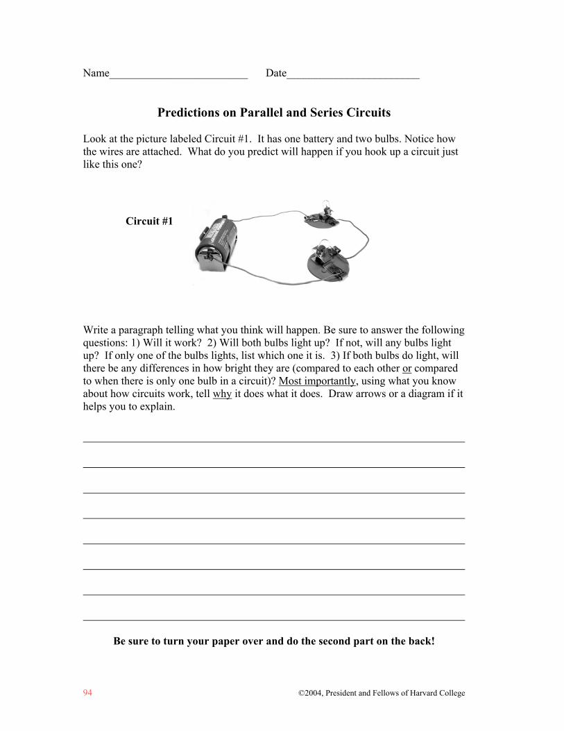
94 ©2004, President and Fellows of Harvard College
Name_________________________ Date________________________
Predictions on Parallel and Series Circuits
Look at the picture labeled Circuit #1. It has one battery and two bulbs. Notice how the wires are attached. What do you predict will happen if you hook up a circuit just like this one? Write a paragraph telling what you think will happen. Be sure to answer the following questions: 1) Will it work? 2) Will both bulbs light up? If not, will any bulbs light up? If only one of the bulbs lights, list which one it is. 3) If both bulbs do light, will there be any differences in how bright they are (compared to each other or compared to when there is only one bulb in a circuit)? Most importantly, using what you know about how circuits work, tell why it does what it does. Draw arrows or a diagram if it helps you to explain.
Be sure to turn your paper over and do the second part on the back!
Circuit #1

©2004, President and Fellows of Harvard College 95
Look at the picture labeled Circuit #2. It also has one battery and two bulbs. Notice how the wires are attached. What do you predict will happen if you hook up a circuit just like this one? Write a paragraph telling what you think will happen. Be sure to answer the following questions: 1) Will it work? 2) Will both bulbs light up? If not, will any bulbs light up? If only one of the bulbs lights, list which one it is. 3) If both bulbs do light, will there be any differences in how bright they are (compared to each other or compared to when there is only one bulb in a circuit)? Most importantly, using what you know about how circuits work, tell why it does what it does. Draw arrows or a diagram if it helps you to explain.
Read over BOTH of your answers and make sure that they are clear and well-explained.
Circuit #2

Student Example: Predictions on Parallel and Series Circuits Analyzing a Series Circuit
96 ©2004, President and Fellows of Harvard College
Notice how this student uses a traveling or substance notion of electrical flow. The underlying causal model is at best Cyclic Sequential and reveals that the student does not attend to the whole circuit at once as a system. Rather s/he reasons that the electricity will reach certain components before it reaches others.
Circuit #1
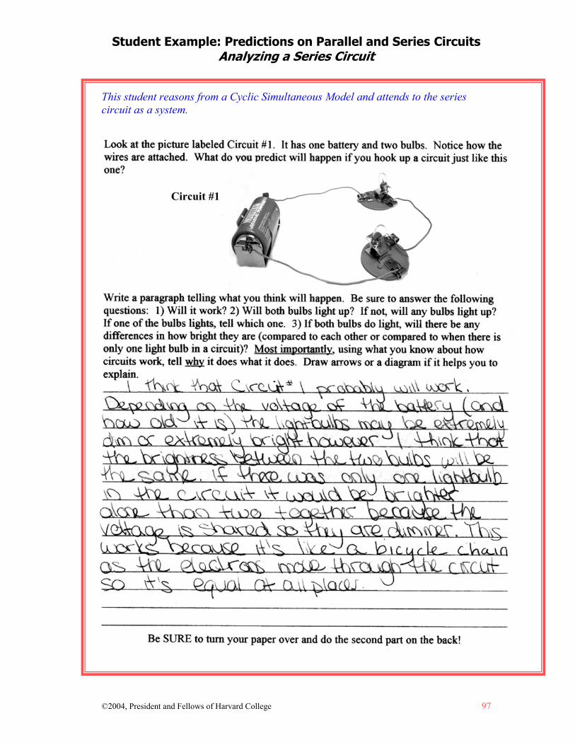
Student Example: Predictions on Parallel and Series Circuits Analyzing a Series Circuit
©2004, President and Fellows of Harvard College 97
This student reasons from a Cyclic Simultaneous Model and attends to the series circuit as a system.
Circuit #1
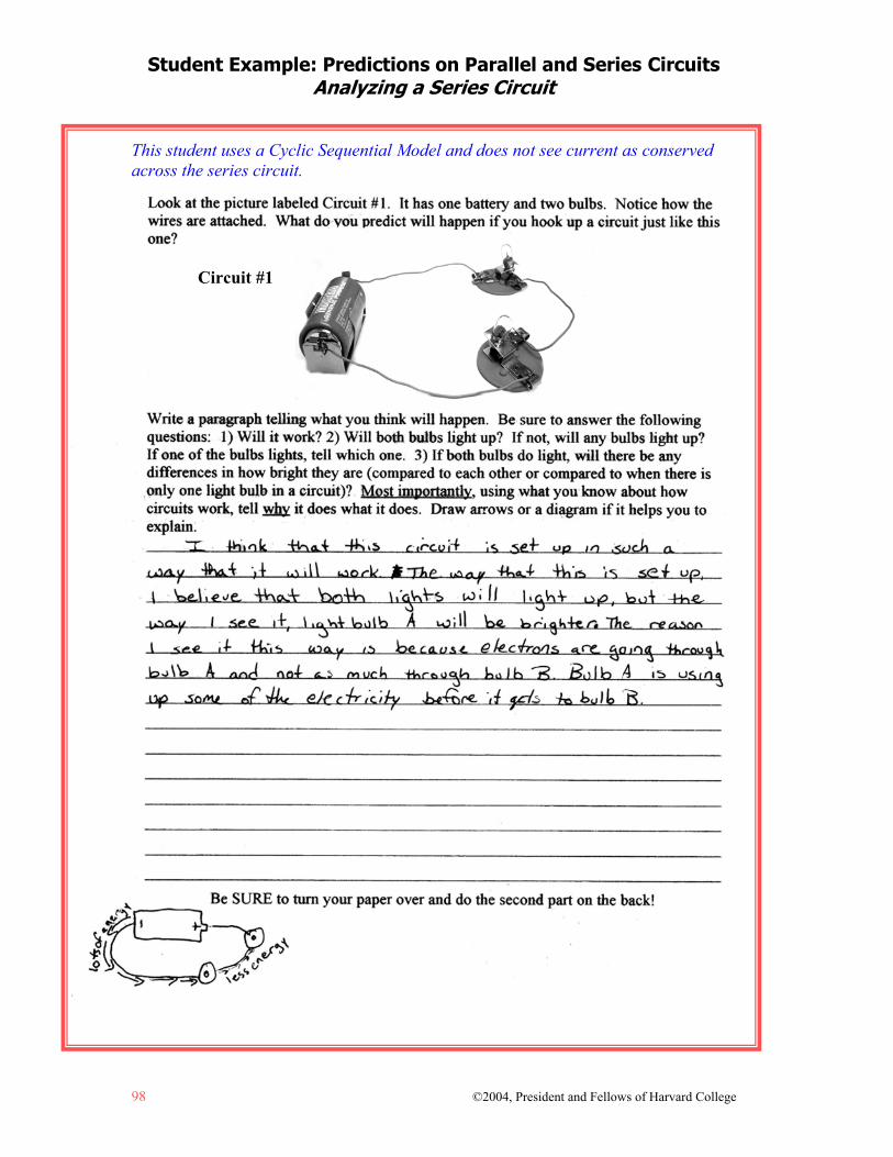
Student Example: Predictions on Parallel and Series Circuits Analyzing a Series Circuit
98 ©2004, President and Fellows of Harvard College
This student uses a Cyclic Sequential Model and does not see current as conserved across the series circuit.
Circuit #1
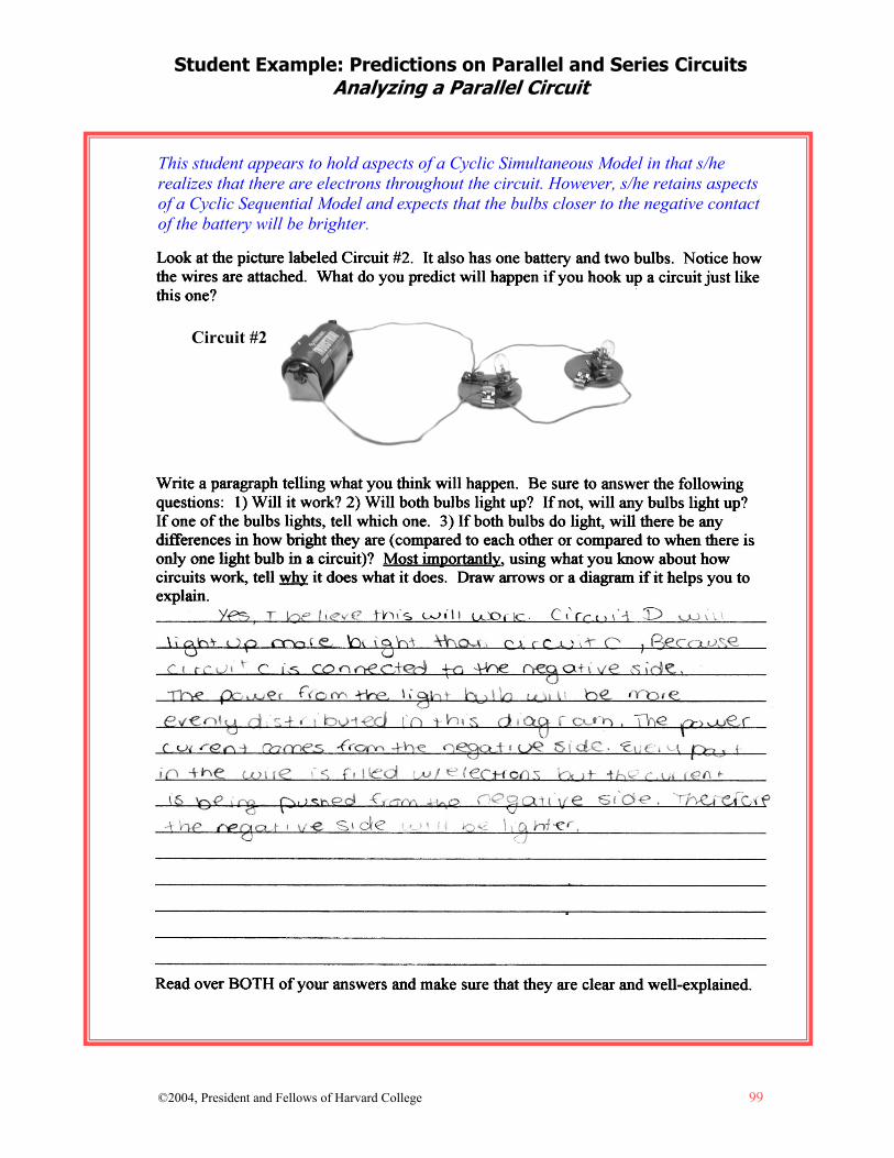
Student Example: Predictions on Parallel and Series Circuits Analyzing a Parallel Circuit
©2004, President and Fellows of Harvard College 99
This student appears to hold aspects of a Cyclic Simultaneous Model in that s/he realizes that there are electrons throughout the circuit. However, s/he retains aspects of a Cyclic Sequential Model and expects that the bulbs closer to the negative contact of the battery will be brighter.
Circuit #2

Student Example: Predictions on Parallel and Series Circuits Analyzing a Parallel Circuit
100 ©2004, President and Fellows of Harvard College
This student reasons from a Cyclic Simultaneous Model and reasons about the circuit as a system. This leads the student to realize that both bulbs will light.
Circuit #2
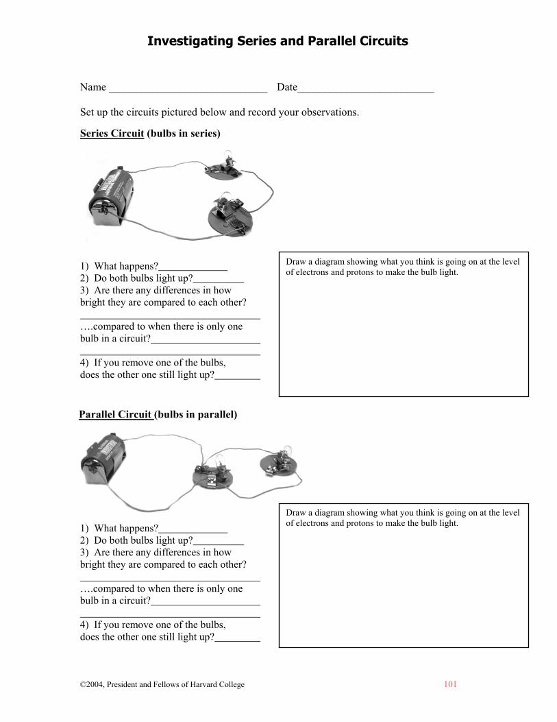
Investigating Series and Parallel Circuits
©2004, President and Fellows of Harvard College 101
Name _____________________________ Date_________________________ Set up the circuits pictured below and record your observations.
1) What happens? 2) Do both bulbs light up? 3) Are there any differences in how bright they are compared to each other? ….compared to when there is only one bulb in a circuit? 4) If you remove one of the bulbs, does the other one still light up?
1) What happens? 2) Do both bulbs light up? 3) Are there any differences in how bright they are compared to each other? ….compared to when there is only one bulb in a circuit? 4) If you remove one of the bulbs, does the other one still light up?
Draw a diagram showing what you think is going on at the level of electrons and protons to make the bulb light.
Draw a diagram showing what you think is going on at the level of electrons and protons to make the bulb light.
Series Circuit (bulbs in series)
Parallel Circuit (bulbs in parallel)
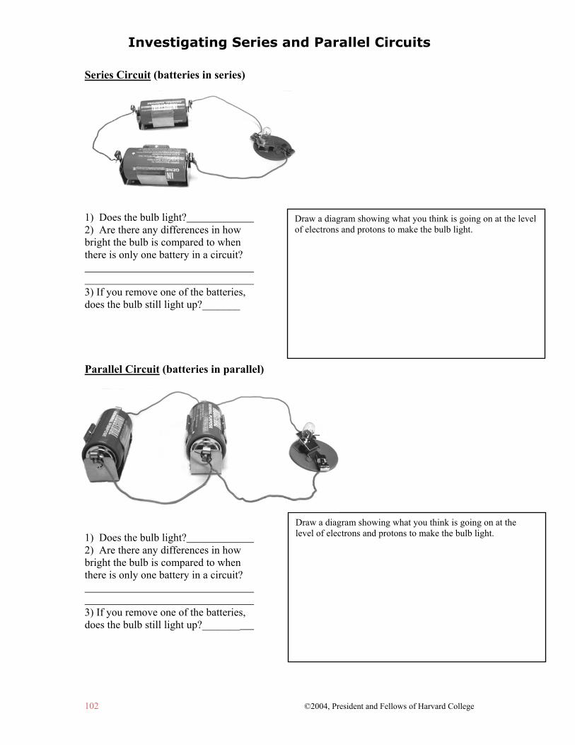
Investigating Series and Parallel Circuits
102 ©2004, President and Fellows of Harvard College
Series Circuit (batteries in series)
1) Does the bulb light? 2) Are there any differences in how bright the bulb is compared to when there is only one battery in a circuit? 3) If you remove one of the batteries, does the bulb still light up?_______ Parallel Circuit (batteries in parallel)
1) Does the bulb light? 2) Are there any differences in how bright the bulb is compared to when there is only one battery in a circuit? 3) If you remove one of the batteries, does the bulb still light up?_______
Draw a diagram showing what you think is going on at the level of electrons and protons to make the bulb light.
Draw a diagram showing what you think is going on at the level of electrons and protons to make the bulb light.

Student Example: Investigating Series and Parallel Circuits
©2004, President and Fellows of Harvard College 103

Student Example: Investigating Series and Parallel Circuits
104 ©2004, President and Fellows of Harvard College
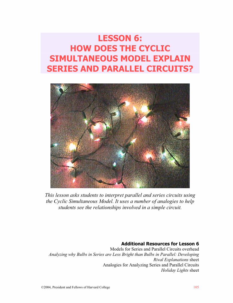
©2004, President and Fellows of Harvard College 105
LESSON 6: HOW DOES THE CYCLIC
SIMULTANEOUS MODEL EXPLAIN SERIES AND PARALLEL CIRCUITS?
This lesson asks students to interpret parallel and series circuits using the Cyclic Simultaneous Model. It uses a number of analogies to help
students see the relationships involved in a simple circuit. Additional Resources for Lesson 6
Models for Series and Parallel Circuits overhead Analyzing why Bulbs in Series are Less Bright than Bulbs in Parallel: Developing
Rival Explanations sheet Analogies for Analyzing Series and Parallel Circuits
Holiday Lights sheet

©2004, President and Fellows of Harvard College 107
Lesson 6: How does the Cyclic Simultaneous Model Explain Series and Parallel Circuits?
Understanding Goals Subject Matter
When you arrange two bulbs in series, they will shine less brightly than if there was only one bulb. They will also shine less brightly than if they were arranged in parallel. This is because there is less current in the circuit due to greater resistance.1
When you arrange two bulbs in parallel, they will shine as brightly as if there were only one bulb. (If you keep adding bulbs in parallel, eventually they will get dimmer due to the voltage of the battery.) This is because the amount of resistance for any single complete battery and bulb circuit stays the same. (Each bulb is, in effect, connected directly to the battery.)
Causality
Using a Cyclic Simultaneous Model to reason about series and parallel circuits helps us to focus on what happens across the system as a whole, rather than focusing locally at each bulb.
Background Information Analyzing Parallel and Series Circuits Using the Cyclic Simultaneous Model
Students generate explanations, starting from whatever model they hold for the simple circuit, to explain why bulbs behave as they do in series or in parallel circuits. Their underlying models can be so strong that sometimes students actually perceive what they expect to see happening and are unable to see what really happens in their experiments. Therefore, it is important to have students discuss their various ideas and share what they think is going on. It is important to give them opportunities to use the Cyclic Simultaneous Model to explain what happens with bulbs in series and in parallel because it helps them to focus on the system as a whole, not just on local features of it. An example of this is focusing on what happens to each bulb separately, as opposed to what happens to all the bulbs together as a system.
1 More precisely, this is because of a combination of less current (due to the greater resistance) and
less voltage drop across each bulb.
Causal Patterns in Simple Circuits: How does the Cyclic Simultaneous Model Explain Series and Parallel Circuits?
108 ©2004, President and Fellows of Harvard College
The Importance of Presenting AND Critiquing Analogies
Further, the analogies that teachers often use to explain the simple circuit can lead tonew misconceptions or support ones that students already hold. For instance, the “water in a hose” model, presented in this lesson and commonly used in units on electrical circuits, furthers the notion of electricity as substance-like rather than process-like. While this model can be useful in helping students to think about the relationship between voltage and current, the potential misconceptions it introduces also need to be discussed. One could just decide not to present potentially problematic analogies to students. However, when analogies are common enough, it is likely that students will hear them at some time or another. Therefore, it is better to address the embedded cognitive challenges in the analogy rather than avoid it altogether.
Causal Patterns in Simple Circuits: How does the Cyclic Simultaneous Model Explain Series and Parallel Circuits?
©2004, President and Fellows of Harvard College 109
Lesson Plan Materials
Analyzing Why Bulbs in Series are Less Bright than Bulbs in Parallel: Developing Rival Explanations sheet
Models for Series and Parallel Circuits overhead (optional) Analogies for Analyzing Series and Parallel Circuits sheet Holiday Lights sheet One string of holiday lights (optional)
Prep Step
Review the lesson plan, background information, and understanding goals. Photocopy: Analyzing Why Bulbs in Series are Less Bright than Bulbs in
Parallel: Developing Rival Explanations; Holiday Lights; and Analogies for Analyzing Series and Parallel Circuits sheets (pp. 114-117) for each student.
Make an overhead of Models for Series and Parallel Circuits (p. 113). (This is optional. It can be drawn on the board instead.)
Analyze Thinking Step 1: Analyzing the WHY Behind What Happens
Hand out the sheet, Analyzing Why Bulbs in Series are Less Bright than Bulbs in Parallel: Developing Rival Explanations (p. 114) and have students think about the questions. Explain that the purpose of generating a rival explanation is to keep your mind open to other possibilities and keep you from becoming too invested in your first idea.
As a group, discuss the rival explanations that students created to explain what is going on with bulbs in series and in parallel. Are there parts of the explanations that they agree with? Are there parts of the explanations that they disagree with?
Note to Teacher: This lesson does not have an “Explore Outcomes” or “RECAST Thinking” step because it follows up on the experimentation in the previous lesson.
Explore Causality Step 2: Analyzing Series and Parallel Circuits with a Cyclic Simultaneous Model
Explain to students that they are going to use the Cyclic Simultaneous Model for thinking about what is going on.
Draw the following diagrams on the board or use an overhead of Models for Series and Parallel Circuits on page 113 to project on an overhead projector.
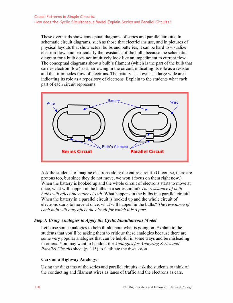
Causal Patterns in Simple Circuits: How does the Cyclic Simultaneous Model Explain Series and Parallel Circuits?
110 ©2004, President and Fellows of Harvard College
These overheads show conceptual diagrams of series and parallel circuits. In schematic circuit diagrams, such as those that electricians use, and in pictures of physical layouts that show actual bulbs and batteries, it can be hard to visualize electron flow, and particularly the resistance of the bulb, because the schematic diagram for a bulb does not intuitively look like an impediment to current flow. The conceptual diagrams show a bulb’s filament (which is the part of the bulb that carries electron flow) as a narrowing in the circuit, indicating its role as a resistor and that it impedes flow of electrons. The battery is shown as a large wide area indicating its role as a repository of electrons. Explain to the students what each part of each circuit represents.
Series Circuit Parallel Circuit Ask the students to imagine electrons along the entire circuit. (Of course, there are protons too, but since they do not move, we won’t focus on them right now.) When the battery is hooked up and the whole circuit of electrons starts to move at once, what will happen in the bulbs in a series circuit? The resistance of both bulbs will affect the entire circuit. What happens in the bulbs in a parallel circuit? When the battery in a parallel circuit is hooked up and the whole circuit of electrons starts to move at once, what will happen in the bulbs? The resistance of each bulb will only affect the circuit for which it is a part.
Step 3: Using Analogies to Apply the Cyclic Simultaneous Model
Let’s use some analogies to help think about what is going on. Explain to the students that you’ll be asking them to critique these analogies because there are some very popular analogies that can be helpful in some ways and be misleading in others. You may want to handout the Analogies for Analyzing Series and Parallel Circuits sheet (p. 115) to facilitate the discussion.
Cars on a Highway Analogy:
Using the diagrams of the series and parallel circuits, ask the students to think of the conducting and filament wires as lanes of traffic and the electrons as cars.
Bulb’s filament
Battery Wire Wire

Causal Patterns in Simple Circuits: How does the Cyclic Simultaneous Model Explain Series and Parallel Circuits?
©2004, President and Fellows of Harvard College 111
Notice the places where the bulbs are; it’s like a tunnel or narrowed lane and only a certain amount of traffic can get through at once—for the purposes of illustration, say that only one lane of traffic can get through and the lanes on either side have to merge. The cars in the side lanes can’t merge or flow through the tunnel very well. How many lanes will be flowing in each type of circuit? The series circuit will have one lane of traffic flowing, and it will be tough going where the bulbs/tunnels are. Since the electrons/cars can’t go through easily, traffic will be affected in the entire circuit/highway. Everyone is affected because fewer cars can get through the tunnels, so movement in the whole circuit is limited.
The parallel circuit will have two lanes flowing because electrons/cars can go through either tunnel/filament; there are twice as many lanes to go through as in the series circuit. Because the electrons/cars can’t get through easily, the bulbs/tunnels will still affect the entire circuit (because fewer cars can get through the tunnels than through the circuit wire), but much less so than for the series circuit.
What are some ways that the Cars on a Highway analogy works? • It captures the difference in amount of flow of current between series and
parallel circuits. • It builds on the Cyclic Simultaneous Model to show what is going on. • It explains the difference in resistance between the two circuits to show
why, given the same amount of voltage, one allows there to be more flow of current (parallel) than the other (series).
• It forces students to view the circuit as a system, because if cars in one part can’t move, neither can cars in another part. It’s like one big traffic jam.
What are some ways that the Cars on a Highway analogy doesn’t work? • It makes it look like there are a few “rows” of electrons when in fact, there
are many. Electrons don’t move neatly in lines the way cars do. • It doesn’t communicate the idea of how difficult it actually is for electrons
to move through the filaments. • It might give the impression that resistance has to do with the speed of
electron movement. Resistance is really NOT about speed, it is about how difficult it is for electrons to get through and how many of them can get through.
• It doesn’t account for voltage. The closest analogy is horsepower or speed, but again this leads to the idea that the effect of resistance is speed/slowness, not ease/difficulty.
Causal Patterns in Simple Circuits: How does the Cyclic Simultaneous Model Explain Series and Parallel Circuits?
112 ©2004, President and Fellows of Harvard College
• It may lead students to think that there is half as much resistance in a parallel circuit, because there are twice as many “lanes.” This is not the case; there isn’t a simple relationship between resistance in parallel and series circuits.
Water in a Hose Analogy:
Another analogy that people like to use is “water in a hose.” The circuit is thought of as a hose. When you turn on the water, the amount that you turn on (or the pressure you create) is analogous to the voltage or amount of push that the battery has. If you clamp down on any part of the hose, it is analogous to adding resistance the way that a bulb adds resistance. The water has a harder time getting through the clamped part of the hose, and affects all of the water behind it. The current is represented by how much water flows, and is the result of how much water pressure/voltage there is and how much clamping/resistance there is. If you clamp multiple places in the hose, less water is able to get through the entire hose. How does this help in understanding series and parallel circuits? How much “water” will flow through each? The series circuit will have two or more clamped spots but only one hose, and it will be difficult for water to go through the clamped spots (bulbs). Since water can’t go through the clamped parts easily, this will affect the water on both sides of the clamps. Less water will flow in the entire hose and less will trickle out the end of the hose.
The parallel circuit will have two or more clamped spots too, but it will branch from one hose into two (or more) hoses for the water to go through. The water can’t get through the clamped spots easily, so it affects the water on both sides of the clamp, but less so than for the series circuit because there are more hoses to travel through.
What are some ways that the Water in a Hose analogy works? • It turns students’ attention to the systemic nature of what is going on. • It shows the relationship between voltage (how much you turn the spigot),
resistance (how many kinks in the hose), and current (how much water is flowing).
• It explains the difference in resistance between the two circuits and shows why, given the same amount of voltage, one allows for more current (parallel) than the other (series).
• Many students have experience with hoses, so they understand the components of this analogy well.
What are some ways that the Water in a Hose analogy doesn’t work? • It gives the erroneous idea that electrons are substance-like, rather than
process-like.

Causal Patterns in Simple Circuits: How does the Cyclic Simultaneous Model Explain Series and Parallel Circuits?
©2004, President and Fellows of Harvard College 113
• The hose is empty before the water enters it. This could inadvertently reinforce a Cyclic Sequential Model instead of a Cyclic Simultaneous Model.
• It does a nice job conveying that less water gets through, but doesn’t convey the aspects of resistance that are related to difficulty of electron movement.
• In order to think about the result of resistance on current, one has to think about what comes out of the hose, but a circuit does not have a similar “ending.” This could inadvertently reinforce a Linear Model.
• In reality, one clamp on a water hose would decrease the flow of water. However, it is not clear whether a second clamp would actually affect the system in the same way that a second light bulb adds additional resistance in a circuit. So increasing the number of clamps is not directly analogous to adding bulbs and therefore increasing resistance.
What questions do students have? What do they understand? What do they find confusing about the analogies? Encourage them to explain what they think is helpful and not so helpful about the analogies. Are there any other analogies that the students can think of? Ask the students to put their heads together with a neighbor and to think of other analogies to explain what is going on with parallel and series circuits. Share and discuss whatever ideas they come up with.
Review, Extend, Apply Step 4: Analyzing Analogies for Series and Parallel Circuits
Ask students to choose one of the analogies presented, or one that they or others thought of in class, and explain it in their own words and drawings. They should also look for ways to fix the “problems” that we identified with the analogy they choose.
Step 5: Making Connections
Ask students to think about the examples of parallel and series circuits that they looked for around home and school in Step 3 of Lesson 5. Together, analyze a few of the examples in terms of the analogies discussed in this lesson. Ask, “Do you think that the lights in your school are wired in series or in parallel? Decide which you think it is and come up with an argument to support it.”
Students might consider what happens when one light goes out in their room. Do the others go out, too? If it was a simple series circuit, they would. It would be inconvenient if one burned-out bulb affected the lights in the entire building!
Causal Patterns in Simple Circuits: How does the Cyclic Simultaneous Model Explain Series and Parallel Circuits?
114 ©2004, President and Fellows of Harvard College
Perhaps they also considered how much resistance such a long series of lights would entail. A lot of voltage would be necessary to have enough light. One example that many students come up with is holiday lights. However, unless the lights are quite old, how they work is not as straightforward as it would seem. The sheet, Holiday Lights (pp. 116-117) can be used with students as an explanation for how holiday lights work
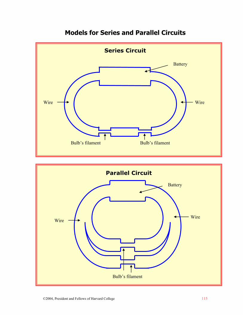
©2004, President and Fellows of Harvard College 115
Parallel Circuit
Bulb’s filament
Models for Series and Parallel Circuits
Series Circuit
Bulb’s filament Bulb’s filament
Battery
WireWire
Wire Wire
Battery
116 ©2004, President and Fellows of Harvard College
Name _______________ Date_________________ Analyzing Why Bulbs in Series are Less Bright than Bulbs in
Parallel: Developing Rival Explanations
When you hook up bulbs in series, they are less bright than when you hook up bulbs in parallel. What do you think is going on? Explain what you think is happening. Draw a diagram on the back if it helps you to explain. Now that you have finished one possible explanation, try to think of another. Explain your second idea. Draw a diagram if it helps you to explain. Try to make your second idea as different as possible from your first.
Now, read each idea over carefully to make sure that there aren’t any gaps in your explanation. If there are, make a carrot (^) and add the missing piece of the explanation.
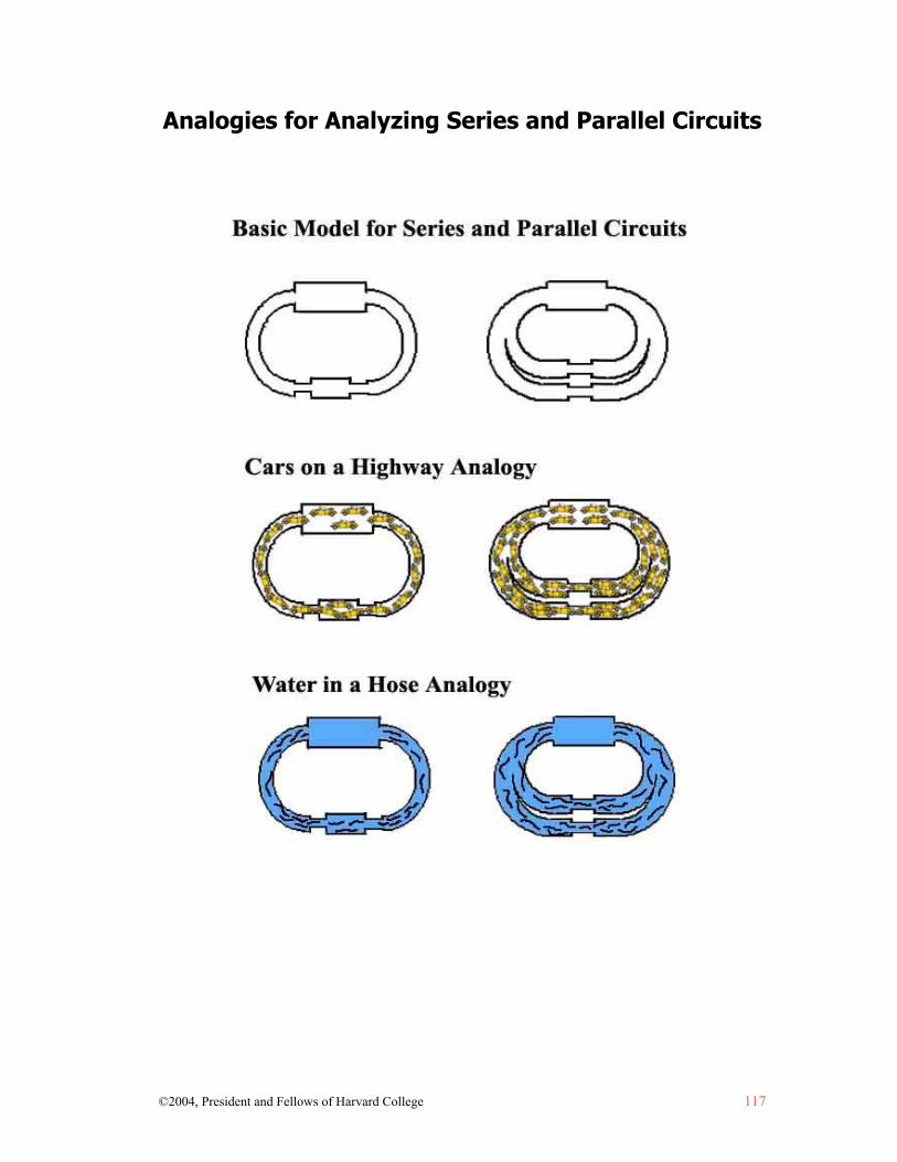
©2004, President and Fellows of Harvard College 117
Analogies for Analyzing Series and Parallel Circuits

118 ©2004, President and Fellows of Harvard College
Holiday Lights How do you think holiday lights work? What kind of electrical circuit do you think they make? Let’s think about what we know about them. Holiday lights often come in sets of 50 bulbs. Sometimes if one bulb goes out the whole strand of lights will no longer work. Which kind of circuit would this be, series or parallel? How you can tell what kind of circuit you have? For starters, imagine a strand of holiday lights. There is a plug at one end that goes into a wall socket. Along the strand, you have the 50 mini-lights that are connected to each other. Look at the diagram. If one bulb was removed from this circuit, what do you think would happen? What about when a bulb goes dead? The entire circuit would be broken, and none of the lights would light. This is a series circuit. How come my holiday lights can have a burnt-out bulb and still work? Scientists developed bulbs that have something inside them called an internal shunt. A shunt is a strand of wire that gets wrapped around the two posts inside the bulb. When the filament breaks (see Shunt Image for detail) the shunt gets really hot and a coating burns off, activating the shunt. The shunt allows the current to continue to flow even if the bulb is no longer working, and therefore the strand stays lit!
Plug
Mini-lights
Wire

©2004, President and Fellows of Harvard College 119
Shunt Image How come some holiday lights have three wires? There are three wires in most holiday lights sold today. This is because the third wire attaches to a socket so another strand can be attached. The dashed diagonal line in the diagram below indicates the third wire. This wire attaches to the outlet at the end of the strand. It will light up the next string of holiday lights plugged into it. When another set of lights is plugged in, it becomes a parallel circuit. So how do the lights receive the charge? It may not be the way you imagine! The circuit includes the socket, the solid diagonal wire and the top strand, which connects the lights and the socket.
This is the shunt wire that wraps
around the 2 posts inside the
bulb.
This is the broken filament, which causes the shunt to activate and
keeps the strand of bulbs lit.
3rd wire
The next strand would plug in
the end.

©2004, President and Fellows of Harvard College 121
LESSON 7 HOW DO OHM’S LAW AND
CONSTRAINT-BASED REASONING HELP IN THINKING ABOUT
CIRCUITS?
This lesson offers a bridge between different conceptual models using Cyclic Simultaneous Causality and algorithms for reasoning about voltage,
resistance, and the resulting current. It is designed to help students see the links between resistance, voltage, and current so that the relationship known
as Ohm’s Law makes sense to them. It involves reasoning from the constraints in the system.
There are no Additional Resources for Lesson 7

©2004, President and Fellows of Harvard College 123
Lesson 7: How Do Ohm’s Law and Constraint-Based Reasoning Help in Thinking About Circuits?
Understanding Goals Subject Matter
Ohm’s Law specifies the relationship between voltage, resistance, and current. Ohm’s Law is I = V/R, where I = current, V = voltage, and R = resistance.
Causality
Current can be viewed as caused by the relationship between voltage and resistance. You can’t manipulate current directly. You can only manipulate the relationship between voltage and resistance to change the current.
Instead of reasoning about the circuit by using a causal model, you can reason about it using the “constraints” (resistance, voltage, and current). Many scientists think of it this way. Constraint-based reasoning makes it easy to do calculations. Difficulties can arise if you forget how the constraints are related to each other, so it helps to have a causal model to fall back on.
Background Information Causal Models and Constraint-Based Reasoning
Ohm’s Law asks students to think about the relationship between voltage, resistance, and current. Ohm’s Law specifies that I = V/R where I = current, V = voltage, and R = resistance. Voltage (V) is measured in volts. The voltage of a battery is typically listed on the side of the battery. Voltage is a difference in charge measured between two points. In a simple circuit, the voltage of the battery is essentially the difference in charge between each node of the battery.1 Current (I) is measured in amps. The current or rate of flow can be measured at any point along the circuit. Resistance (R) is measured in ohms. It is a characteristic that describes the conductivity of material, and each component of the circuit has a constant value of resistance.
1 The actual voltage is really a little less due to the internal resistance of the battery. At this point, when
students are learning to reason across the whole circuit as a system, it is helpful to think of the voltage as one number across the circuit. However, as students start to learn about more complex circuits, they will need to reason about the differences in voltage (and corresponding voltage drops) between components of the system. Therefore, we introduce the idea that voltage is the difference in charge between the battery nodes even though students may find it simpler to first think about voltage as the number of volts that they read on the side of the battery.
Causal Patterns in Simple Circuits: How Do Ohm’s Law and Constraint-Based Reasoning Help in Thinking About Circuits?
124 ©2004, President and Fellows of Harvard College
Typically, Ohm’s Law is taught by having students memorize it. However, that makes it difficult for students to reconstruct it if they forget parts of it. Understanding the Cyclic Simultaneous Model allows students to reason out why Ohm’s Law applies and to reconstruct the relationships it describes if they forget them. The Cyclic Simultaneous Model offers a more conceptually oriented model to support the more mathematically oriented, constraint-based model. Thinking About Current as Caused
This lesson illustrates the relationship between each of the variables in Ohm’s Law. It allows you to see how these relationships work by letting you manipulate the variables that you have control over (voltage and resistance) and assessing the impact this has on the other variable (current). You can manipulate the voltage (adding more batteries or higher voltage batteries, for instance) or the resistance (by adding more bulbs, for instance), and changes in the amount of current are the result. Manipulating these variables helps students to realize that the amount of current in a circuit is caused by the amount of voltage and resistance in the circuit.

Causal Patterns in Simple Circuits: How Do Ohm’s Law and Constraint-Based Reasoning Help in Thinking About Circuits?
©2004, President and Fellows of Harvard College 125
Lesson Plan Materials
Re-sealable plastic bag, 1 per pair of students, containing: • “D” cell battery, 3 per pair of students • Flashlight bulb, 4 per pair of students • Wire, (insulated copper wire with plastic coating, apx. 6 inches long
with copper ends exposed), 10 per pair of students • Bulb holders, 4 per pair of students • Battery holders, 3 per pair of students
Overhead of Models for Series and Parallel Circuits on p. 113 For voltage demonstration:
• 9 volt battery • “D” cell battery • Household bulb
Prep Step
Review the lesson plan, background information, and understanding goals. Gather materials for demonstration and put all other materials in the bags.
Analyze Thinking Step 1: Checking Current Understanding
Ask students to explain, in their own words, what voltage, resistance, and current are. They can write their explanations down or discuss them in small groups. Gather their ideas.
Remind the students that voltage can be thought of as a “push” from the battery. Remind them about the drawing of the battery and how we discussed the power of the battery to push the electrons away from the protons (where they are attracted) and towards the negatives (where they are repelled). This power is voltage. It is measured in volts. Resistance can be thought of as opposition to the flow of electric current. It is measured in ohms. Current flow results from the amount of voltage and resistance, and is measured in amperes, or amps.
Find out what ideas students have about how voltage, resistance, and current relate to each other based on their explorations with parallel and series circuits. What do they think will happen in a circuit if any of the variables are increased or decreased?
Causal Patterns in Simple Circuits: How Do Ohm’s Law and Constraint-Based Reasoning Help in Thinking About Circuits?
126 ©2004, President and Fellows of Harvard College
Note to Teacher: This lesson does not have an “Explore Outcomes” or “RECAST Thinking” step because it advances understanding by analysis of the causality involved—the constraint-based relationship between voltage, resistance, and the resulting current.
Explore Causality Step 2: Introducing Ohm’s Law
Show the symbols in Ohm’s Law: V = Voltage; R = Resistance; I = Current.
Pair the students up and give each pair a bag of materials. Have students set up a simple circuit.
Ask, “What can you do to increase the voltage?” Have students explain how they would increase the voltage. Add more batteries in series. What is the result in terms of resistance and current? The resistance stays the same because the students didn’t add any more bulbs (or other resistors), and current increases.
Then ask, “What can you do to increase the resistance?” Have students show how they would increase the resistance. Add more bulbs or other resistors in series. What is the result in terms of voltage and current? Voltage stays the same because they haven’t changed it, and current decreases.
Then ask, “What if you wanted to increase the current?” Have students show what they would do. Add more voltage or decrease the resistance. Ask, “Can you directly change the current? Why or why not?”
Step 3: Calculating with Ohm’s Law
Introduce Ohm’s Law: I = V/R.
Calculate some examples together: • What is the current if the voltage is 9 volts and there is a resistance of 4.5
ohms? 2 amps.
• What is the current if the voltage is 220 volts and the resistance is 40 ohms? 5.5 amps.
• Can you figure out the voltage if you know the current and resistance? Yes. You just adjust the equation to V = I x R. Calculate some examples together.
• What is the voltage if the current is 5 amps and the resistance is 25 ohms? 125 volts.
• What is the voltage if the current is 12 amps and the resistance is 4 ohms? 48 volts.
Causal Patterns in Simple Circuits: How Do Ohm’s Law and Constraint-Based Reasoning Help in Thinking About Circuits?
©2004, President and Fellows of Harvard College 127
• Can you figure out the resistance if you know the current and voltage? Yes. You just adjust the equation to R = V/I. Calculate some examples together.
• What is the resistance if the voltage is 110 volts and the current is 5 amps? 22 ohms.
• What is the resistance if the voltage is 60 volts and the current is 5 amps? 12 ohms.
Students do not need to memorize the three equations; if they know one, they should be able to figure out all three equations without any memorization. They can deduce any equation from the others.
Have students calculate the answers to some math questions about Ohm’s Law.
• If the voltage is 100 volts and the resistance is 4 ohms, what is the current? 25 amps
• If the voltage is 100 volts and the resistance is 50 ohms, what is the current? 2 amps
• If the voltage is 300 volts and the resistance is 50 ohms, what is the current? 6 amps
• If the voltage is 300 volts and the current is 10 amps, what is the resistance? 30 ohms
• If the voltage is 300 volts and the current is 50 amps, what is the resistance? 6 ohms
• If the current is 30 amps and the resistance is 10 ohms, what is the voltage? 300 volts
• If the current is 50 amps and the resistance is 10 ohms, what is the voltage? 500 volts
Ask, “How can we conceptually assess our answers as a check on our computation?” They can check to see if their computation goes in the right direction by knowing that current goes up if there is higher voltage and the resistance stays the same. The current drops if there is lower voltage and the resistance stays the same. The reverse is also true. The current goes up if there is lower resistance and the voltage stays the same. The current drops if there is higher resistance and the voltage stays the same.
Review, Extend, Apply Step 4: Thinking About Which Batteries Can Light Which Bulbs
Show the students a “D” cell battery (1.5 volt), a 9 volt battery, and a large (household size) light bulb. Demonstrate that you can light the bulb with the 9 volt battery but not with the 1.5 volt battery. Ask, “What do you think is going on?” Help students to realize that the ‘D’ cell does not have enough voltage, or

Causal Patterns in Simple Circuits: How Do Ohm’s Law and Constraint-Based Reasoning Help in Thinking About Circuits?
128 ©2004, President and Fellows of Harvard College
“push,” to light the large bulb given the bulb’s resistance. It cannot move enough electrons through the wire at one time. Therefore, the bulb does not light. A 9 volt battery does have enough push.
Step 5: Applying Ohm’s Law to Series and Parallel Circuits
Go back to the Models for Series and Parallel Circuits on page 113 and have students describe what is going on in each case. In the case of series circuits where you are adding more bulbs, you are increasing the amount of resistance in the circuit. In the case of series circuits, where you are adding more batteries, you are increasing the amount of voltage. In the case of parallel circuits where you are adding more bulbs, you are keeping the amount of resistance for each circuit the same. A parallel circuit is just like parallel loops of single-bulb circuits, with each bulb directly connected to both ends of the battery, so each circuit only has the resistance of one bulb, no matter how many parallel bulbs you add. In the case of parallel circuits where you are adding more batteries, you are keeping the amount of voltage for each circuit the same.2
Have students draw a model to show what is going on in at least one set of cases. If there is time, have them draw a model for both sets of cases (where you manipulate resistance and where you manipulate voltage.) You could use this activity as a good embedded assessment to see what the students understand.
Have students share and discuss their models.
2 Technically speaking, Ohm’s Law gives an adequate explanation for parallel bulbs but only part of
the story for series bulbs. From Ohm’s Law, current through two bulbs in a series is half what it is through one bulb alone. But potential difference across each bulb is only half the total battery voltage as well. So half the current and half the voltage means each bulb only gets one fourth the power.
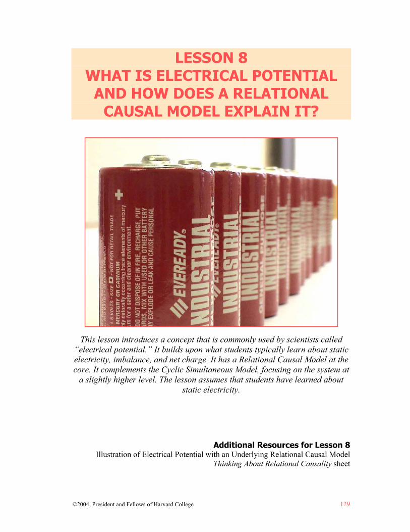
©2004, President and Fellows of Harvard College 129
LESSON 8 WHAT IS ELECTRICAL POTENTIAL
AND HOW DOES A RELATIONAL CAUSAL MODEL EXPLAIN IT?
This lesson introduces a concept that is commonly used by scientists called
“electrical potential.” It builds upon what students typically learn about static electricity, imbalance, and net charge. It has a Relational Causal Model at the core. It complements the Cyclic Simultaneous Model, focusing on the system at
a slightly higher level. The lesson assumes that students have learned about static electricity.
Additional Resources for Lesson 8 Illustration of Electrical Potential with an Underlying Relational Causal Model
Thinking About Relational Causality sheet

©2004, President and Fellows of Harvard College 131
Lesson 8: What is Electrical Potential and How Does a Relational Causal Model Explain It?
Understanding Goals Subject Matter
In a circuit, electric charge flows from areas of greater charge to areas of lesser charge, just as it does in the build-up of static electricity.
The role of the battery in a circuit is to maintain an imbalance in the concentration of electrons between opposite ends of the battery.
Even though the circuit is “full” of electrons when the wires are first hooked up, the electrons and protons are balanced so there is no electrical charge along the wires. (The electrons are equally crowded or spaced out throughout.) It is the movement of imbalance along the wires that results in flow and lights the bulb.
Causality
The concept of “electrical potential” introduces another casual model for thinking about what happens in a circuit. Electrical potential has an underlying Relational Causal Model. The cause of electrical flow has to do with balance and imbalance.
Reasoning about electrical potential and the inherent Relational Causal Model complements a Cyclic Simultaneous Model. Even though they each have a different type of causality at the core, they work to explain electrical flow at different levels of focus within the system.
The concept of electrical potential may appear superficially similar to the Cyclic Sequential Model if students don’t grasp the differences at a deeper level. However, models that use the concept of electrical potential and an underlying Relational Causal Model necessitate that we attend to the whole system at once, not just a part of it.
Background Information Introducing the Concept of Electrical Potential
Scientists often reason about a circuit in terms of “electrical potential” or “electrical differential.” These concepts explain why electrical currents propagate along the wire, and connect nicely to thinking about the circuit using constraint-based reasoning that
Causal Patterns in Simple Circuits: What is Electrical Potential and How Does a Relational Causal Model Explain It?
132 ©2004, President and Fellows of Harvard College
takes into account the entire system and how different variables impact it. The phenomenon is referred to as electrical potential because there is potential energy in a circuit as a result of the difference in charge between the positive and negative poles of the battery. Understanding electrical potential requires a basic understanding of concepts related to static electricity. The concept of electrical potential uses the idea of net excess charge. Before hooking up the wires in a circuit, everything along the wires is balanced. There are electrons and protons all along the wire, as discussed in the Cyclic Simultaneous Model, but they are not charged. There is a charge in the battery because the chemical in the battery carries out “work" to separate protons and electrons. This results in an excess of protons at the positive contact and an excess of electrons at the negative contact. The excess charge propagates through the circuit to the positive terminal. There is a very small transient delay (not noticeable at all) as the circuit gets up to the point where excess negative charge flows along the wire. This point is called “steady state.” The Role of the Battery in Maintaining Electrical Potential
In models based on electrical potential, the battery accomplishes the task of getting the electrons back to the negative contact on the battery, concentrating electrons on the negative contact and leaving a deficit on the positive terminal. This results in the imbalance that causes the electrical flow. The difference in the concentration of electrons between the positive and negative terminals gets distributed along the circuit and causes electrical impulses to move along the circuit. The chemical reaction inside the battery maintains a constant level of imbalance between the positive and negative terminals. Volts are the unit that we use to measure the voltage differential. The chemical particles inside the battery can each only make a single trip carrying a single electron’s worth of charge from one side of the battery to the other. Once it has made its trip, that chemical particle cannot be used again. When does a battery die? When all the chemical material has been moved from one side to the other and there is no more unused chemical left to move electrons and protons. This is why big batteries last longer. Voltage is always measured as a difference in electron crowding (concentration) between two points. A particular spot in a circuit can’t have a voltage. A 1.5 volt battery really means that it will maintain a 1.5 volt difference between its positive and negative terminals. If the concentration goes down between two points, it is referred to as a voltage loss or voltage “drop.” If the concentration goes up between two points, it is a voltage gain. An Underlying Relational Causality
The causality inherent in the concept of electrical potential is a Relational Causal Model. The relationship between two variables rather than one variable or one event causes an outcome. This is the same underlying causal structure involved in thinking about differentials and equilibrium in the topics of pressure or density. This model

Causal Patterns in Simple Circuits: What is Electrical Potential and How Does a Relational Causal Model Explain It?
©2004, President and Fellows of Harvard College 133
builds on an understanding of density and knowledge about balance versus imbalance in terms of electrical charge. Electrical potential focuses on differential and balance. The excess of electrons at the battery’s negative contact and the depletion of electrons (resulting in an excess of protons) at the positive contact results in a differential that causes the electrons to flow away from areas of higher concentration and to areas of lower concentration. The chemicals in the battery perform the “work” of concentrating protons on one end of the battery and electrons on the other. Thinking About a Circuit using Electrical Potential in Comparison to the Cyclic Simultaneous Model
Models that use electrical potential (and the underlying Relational Causality) are less “zoomed-in” than the Cyclic Simultaneous Model, in that they focus less on the behavior of individual particles and more on the behavior of the system as a whole. The Cyclic Simultaneous Model describes the repelling of individual electrons (repelling and being repelled) as the cause of flow. Models based on electrical potential take a different perspective. They look at the behavior of the population or collection of electrons and use net charge as the cause of flow. Like the Cyclic Simultaneous Model, this requires that students look at the circuit as a system and reason about the entire system at once, rather than focusing on portions locally or on one bulb or battery at a time. A Difficult Distinction that Challenges Understanding
A difficulty in presenting the concept of electrical potential and the underlying Relational Causal Model to students too early in their learning is that it shares aspects of the Cyclic Sequential Model that is so embedded in students’ everyday reasoning. In the case of electrical potential, the circuit has electrons all along it before the battery is hooked up, but it is electrically balanced so it does not have net charge. On a surface level, this might fit with a student’s idea that it is empty and will be filled with electricity. Although individual electrons don’t have to travel to get from battery to bulb in the case of electrical potential, the gradient in electron concentration does propagate through the system. This aspect of its behavior IS cyclic sequential in its causal pattern. These overlaps may lead students back to that model, rather than to a more sophisticated model. One way to get around this is to explicitly point out its similarities and its differences to the Cyclic Sequential Model, reminding students of how the Cyclic Sequential Model is problematic.
Causal Patterns in Simple Circuits: What is Electrical Potential and How Does a Relational Causal Model Explain It?
134 ©2004, President and Fellows of Harvard College
Lesson Plan Materials
White board or overhead of the diagram, Illustration of Electrical Potential with an Underlying Relational Causal Model
Thinking About Relational Causality sheet, 1 per student Prep Step
Review the lesson plan, background information, and understanding goals. Prepare white board or overhead of the diagram, Illustration of Electrical
Potential with an Underlying Relational Causal Model (p. 136). Photocopy the sheet, Thinking About Relational Causality, (p. 137), 1 per
student. Analyze Thinking Step 1: Reviewing Concepts from Static Electricity
Remind the students about the ideas of imbalance and net charge from static electricity. Can anyone explain it? Ask them to draw a model that illustrates the concept.
When there are equal numbers of electrons and protons in a part of a material, they are balanced and there is no net electrical charge. When there is an excess of electrons or an excess of protons, there is net electrical charge. Because electrons are repelled by other electrons and attracted to protons (and protons are repelled by other protons and attracted to electrons) they “seek out” balance, i.e. electrons without proton pairs will move away from other electrons and towards protons. This is what happens when you get charged, or “shocked” from, for example, shuffling your feet on the rug. You have an excess of electrons, and you feel a shock when they repel each other and seek out protons by repelling their electron partners and attracting to the protons. Imbalance = charge, and net charge refers to the net difference between the number of electrons and the number of protons when there are more of one than the other.
RECAST Thinking Step 2: Introducing the Concept of Electrical Potential
Explain to the students that you are going to show them another way of explaining a simple circuit. It is similar to the Cyclic Simultaneous Model in some ways, and different in other ways. Both are “scientifically accepted” ways of explaining how a simple circuit works. It uses the concept of “electrical potential.” It is less zoomed in than the Cyclic Simultaneous Model. You still look at what the electrons are doing, but don’t worry about the behavior of individual electrons as much as how they behave as a group.

Causal Patterns in Simple Circuits: What is Electrical Potential and How Does a Relational Causal Model Explain It?
©2004, President and Fellows of Harvard College 135
The model based on electrical potential uses the idea of net excess charge, which the students should have learned when studying static electricity. Draw the following diagram on the board or use the version on page 136 to project with an overhead projector. The narrowest part of the diagram represents the bulb’s filament (the part of the bulb that carries electron flow and acts as a resistor). The widest part at the top represents the battery (the repository of electrons), and the wide bands connecting the battery and the bulb(s) represent the wire. The minus signs throughout the circuit represent electrons. Explain to the students what each part of each circuit represents.
Illustration of Electrical Potential with an Underlying Relational Causal Model Tell your students that before they hook up the wires, the wires are balanced. There are electrons and protons all along the wire, as discussed in the Cyclic Simultaneous Model, but they are not charged. There is a charge in the battery because the chemical in the battery does work to separate protons and electrons. This results in an excess of protons at the positive contact and an excess of electrons at the negative contact. In order to illustrate this, draw all of the negatives at the negative terminal of the battery. If you hook the wires up to the battery but don’t put the bulb in yet, it would look like this. Notice the higher density of electrons on one side and the lower density of electrons on the other.
Illustration of Electrical Potential with an Underlying Relational Causal Model
No Bulb
Bulb’s filament
Causal Patterns in Simple Circuits: What is Electrical Potential and How Does a Relational Causal Model Explain It?
136 ©2004, President and Fellows of Harvard College
Now ask the students to think about where that excess charge is going to go. It is going to move through the circuit to the positive terminal. If they know about air pressure, remind them that things move from areas of greater concentration to areas of lesser concentration. There is a very small transient delay (not noticeable at all) as the circuit gets up to the point where excess electrons flow along the wire. This point is called “steady state.” Explain that the “work” that the battery does results in an excess of protons on one end of the battery and an excess of electrons on the other. This is work because the protons and electrons are attracted to each other and creating excesses of electrons (which repel each other) and protons (which repel each other) requires energy, which is provided by the chemicals in the battery. The accumulation of electrons at the negative contact, and the depletion of electrons at the positive contact as well as the abundance of protons, creates a differential so that the electrons flow away from areas of higher concentration and towards areas of lower concentration of electrons. So what is voltage? Explain that the battery is performing work. The electrons are attracted to the protons. The more electrons that concentrate on the negative terminal, the harder it is for the battery to push more of them over there. The net negative electrical charge is increased at the negative terminal, and the net positive charge is increased at the positive terminal. The higher the voltage of the battery, the greater the chemical potential it has to separate protons and electrons. The chemical has the ability to concentrate electrons on the negative contact, resulting in a differential between the negative contact and other parts of the circuit that results in flow. Volts are the unit by which voltage is measured. Explore Causality Step 3: The Concept of Electrical Potential and Relational Causality
The concept of electrical potential and models based upon it have an underlying causality that is relational. Have the students read the sheet, Thinking About Relational Causality (p. 137), and discuss it together. Have they seen this type of causality in any other science topics that they have studied? It is the underlying causality in air pressure and density differentials, for example.
Step 4: Comparing Models Based on Electrical Potential (with Relational Causality) to those with Cyclic Simultaneous Causality
Discuss how models based on electrical potential that use relational causality are similar to the Cyclic Simultaneous Model and how they are different. In both types, you have to analyze what is going on by looking at the whole system. The Cyclic Simultaneous Model involves thinking about particles as though they are a bicycle chain. The Electrical Potential/Relational Causal Model involves thinking about particles as a continual wave of oscillating movement as electrons repel each other along the circuit.
Causal Patterns in Simple Circuits: What is Electrical Potential and How Does a Relational Causal Model Explain It?
©2004, President and Fellows of Harvard College 137
However, the gradient in amount of “crowdedness” of electrons exists only when the current is flowing through the system. Discuss how the Electrical Potential/Relational Causal Model is similar to the Cyclic Sequential Model. Tell the students that one reason for not showing them the concept of electrical potential first is that it has some similarities to the Cyclic Sequential Model, and could lead them to revert back to that earlier model, which has lots of problems from a scientific point of view. It is similar in that the Cyclic Sequential Model involves something moving along the wires. However, it is usually thought of as a substance, electricity as stuff, rather than a process of electrons repelling other electrons. Because of this, the Cyclic Sequential Model encourages the erroneous view that the current (seen as “stuff”) is used up and that there is less of it available to components further from the battery. It diverts attention from a systemic view of the circuit.
Ask students to raise questions. What is clear? What is still unclear? Discuss answers to their questions. You may need to review ideas about balance and imbalance in static electricity. Raise the question, “If the process is like static electricity, why doesn’t it just stop after one surge like static electricity does? What makes it continue to flow?” The battery maintains a differential.
Review, Extend, Apply Step 5: Assessing Understanding
Ask students to explain the concept of electrical potential and the underlying Relational Causal Model in their own words and then critique it. They should draw a model and write a paragraph or two explaining it. They should include two to three things that they think work well about their model as an explanation; and two to three things that they think don’t work well. They should also list any questions that they have about it.

138 ©2004, President and Fellows of Harvard College
Illustration of Electrical Potential with an Underlying Relational Causal Model
Bulb’s Filament
Battery
Electrons
Wire Wire
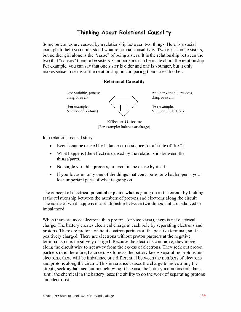
©2004, President and Fellows of Harvard College 139
Thinking About Relational Causality Some outcomes are caused by a relationship between two things. Here is a social example to help you understand what relational causality is. Two girls can be sisters, but neither girl alone is the “cause” of being sisters. It is the relationship between the two that “causes” them to be sisters. Comparisons can be made about the relationship. For example, you can say that one sister is older and one is younger, but it only makes sense in terms of the relationship, in comparing them to each other.
Relational Causality
In a relational causal story:
• Events can be caused by balance or unbalance (or a “state of flux”). • What happens (the effect) is caused by the relationship between the
things/parts. • No single variable, process, or event is the cause by itself. • If you focus on only one of the things that contributes to what happens, you
lose important parts of what is going on. The concept of electrical potential explains what is going on in the circuit by looking at the relationship between the numbers of protons and electrons along the circuit. The cause of what happens is a relationship between two things that are balanced or imbalanced. When there are more electrons than protons (or vice versa), there is net electrical charge. The battery creates electrical charge at each pole by separating electrons and protons. There are protons without electron partners at the positive terminal, so it is positively charged. There are electrons without proton partners at the negative terminal, so it is negatively charged. Because the electrons can move, they move along the circuit wire to get away from the excess of electrons. They seek out proton partners (and therefore, balance). As long as the battery keeps separating protons and electrons, there will be imbalance or a differential between the numbers of electrons and protons along the circuit. This imbalance causes the charge to move along the circuit, seeking balance but not achieving it because the battery maintains imbalance (until the chemical in the battery loses the ability to do the work of separating protons and electrons).
One variable, process, thing or event. (For example: Number of protons)
Another variable, process, thing or event. (For example: Number of electrons)
Effect or Outcome (For example: balance or charge)