CATO-2 Deliverable WP 2.1-D15C Anti-surge system for...
27
Anti-surge system for CO2 compressor Doc.nr: Version: Classification: Page: CATO2-WP2.1-D15c 2013.12.21 Public 1 of 27 This document contains proprietary information of CATO 2 Program. All rights reserved Copying of (parts) of this document is prohibited without prior permission in writing CATO-2 Deliverable WP 2.1-D15C Anti-surge system for CO 2 compressor Prepared by: N. González Díez (TNO) Reviewed by: J. Smeulers (TNO) J. Veltin (TNO) Approved by: J.Brouwer (CATO-2 Director)
Transcript of CATO-2 Deliverable WP 2.1-D15C Anti-surge system for...
Anti-surge system for CO2 compressor
Doc.nr: Version: Classification: Page:
CATO2-WP2.1-D15c 2013.12.21 Public 1 of 27
This document contains proprietary information of CATO 2 Program. All rights reserved
Copying of (parts) of this document is prohibited without prior permission in writing
CATO-2 Deliverable WP 2.1-D15C
Anti-surge system for CO 2 compressor
Prepared by: N. González Díez (TNO)
Reviewed by: J. Smeulers (TNO) J. Veltin (TNO)
Approved by:
J.Brouwer (CATO-2 Director)
Anti-surge system for CO2 compressor
Doc.nr: Version: Classification: Page:
CATO2-WP2.1-D15c 2013.12.21 Public 2 of 27
This document contains proprietary information of CATO 2 Program. All rights reserved
Copying of (parts) of this document is prohibited without prior permission in writing
1 Executive Summary In the process of Carbon Capture and Storage (CCS), the compression stage is of paramount importance. Typically, the stream of CO2 is compressed from pressures of about 1.5 bar to above 100 bar, for which several stages are necessary. Isothermal compression is strived for, since it delivers the optimal efficiency. The compression follows a quasi-isothermal process, by making use of heat exchangers to cool down the stream right after it is compressed and enters the next stage. Because the stream contains a small amount of water, which can cause corrosion and thus jeopardize the integrity of the compressor itself or the transfer line downstream, dehydration also takes place at some stage during the compressor process. Centrifugal compressors are equipped with a so-called anti-surge control (ASC) system. The mission of this system is preventing the compressor to go into surge, i.e. regime of unstable operation in which the flow can even reverse resulting in extreme loads that can lead to catastrophic failures. Anti-surge systems are composed of by-pass lines around the compressor, with an anti-surge valve that is closed during the normal operation of the compressor. Should the ASC system detect the appearance of surge, then the AS valve will open to alleviate the pressure downstream of the compressor. The extreme pressures necessary at the outlet of the compressor, as well as the presence of heat exchangers and separators in between the different stages, poses a number of technical challenges and uncertainties on the design of the anti-surge control system. More specifically, first the ASC system philosophy needs to be evaluated. This involves checking whether a single ASC system for all stages of the compressor is sufficient to prevent surge in any of the stages, or on the contrary, an ASC system per stage is necessary. The effectiveness of using hot or cold by-pass should also be assessed. Secondly, typical parameters such as the volume downstream of each stage, the response time of the actuator on the AS valve, as well as the inertia in the compressor present uncertainties due to the presence of the heat exchangers and the separator(s). Another effect typical of the CCS application is the icing formation due to Joule-Thomson cooling, when the stream is isenthalpically expanded from a high to a low pressure, as it happens in an AS valve. One solution to this problem is steam-tracing the A/S valve to keep the temperatures above a certain value. The current study investigates further into the issues discussed above. General guidelines on the design of the anti-surge system are provided. Since a CCS system design with a sufficient level of detail has not been available at the time of the study, corroboration of the guidelines can not be proved as of yet by means of simulation. Steps into this direction have been taken by proactively performing preliminary design of parts of the system. Within this task, first a preliminary design of an integrally-geared compressor needs to be done to be able to obtain the compressor performance curves which determine the conditions under which surge can be expected. Estimations for the dimensions of the heat exchanger and separators are needed to complete a dynamic model of the system, built into an enhanced version of the PULSIM simulation tool. Several configurations of the anti-surge system are then tested by means of System Dynamics Simulation (SDS), in which the behaviour in time of the compressor stages can be fully studied.
Anti-surge system for CO2 compressor
Doc.nr: Version: Classification: Page:
CATO2-WP2.1-D15c 2013.12.21 Public 3 of 27
This document contains proprietary information of CATO 2 Program. All rights reserved
Copying of (parts) of this document is prohibited without prior permission in writing
Distribution List (this section shows the initial distribution list) External Copies Internal Copies
Document Change Record (this section shows the historical versions, with a short description of the updates) Version Nr of pages Short description of change Pages 2010.02.29 First Draft for review by partners
Anti-surge system for CO2 compressor
Doc.nr: Version: Classification: Page:
CATO2-WP2.1-D15c 2013.12.21 Public 4 of 27
This document contains proprietary information of CATO 2 Program. All rights reserved
Copying of (parts) of this document is prohibited without prior permission in writing
2 Table of Content 1 Executive Summary ................................. .................................................. 2
2 Table of Content .................................. ....................................................... 4
3 Applicable/Reference documents and Abbreviations .. .......................... 5
3.1 Applicable Documents ................................................................................................... 5 3.2 Reference Documents ................................................................................................... 5 3.3 Abbreviations ................................................................................................................ 5
4 Introduction ...................................... .......................................................... 6
4.1 Compression system for CCS applications .................................................................... 7
5 Anti-surge control systems ........................ ............................................... 9
5.1 Normal operating scenario for CCS applications ............................................................ 9 5.2 Anti-surge control components ...................................................................................... 9
6 Anti-surge system layout .......................... .............................................. 12
7 Joule-Thomson effect in anti-surge valves ......... .................................. 14
8 System Dynamics Simulations for ASC evaluation .... .......................... 18
8.1 General information System Dynamics Simulations ..................................................... 18 8.2 Preliminary design of the system ................................................................................. 18
9 Conclusions ....................................... ...................................................... 27
Anti-surge system for CO2 compressor
Doc.nr: Version: Classification: Page:
CATO2-WP2.1-D15c 2013.12.21 Public 5 of 27
This document contains proprietary information of CATO 2 Program. All rights reserved
Copying of (parts) of this document is prohibited without prior permission in writing
3 Applicable/Reference documents and Abbreviations
3.1 Applicable Documents (Applicable Documents, including their version, are documents that are the “legal” basis to the work performed) Title Doc nr Version AD-01d Toezegging CATO-2b FES10036GXDU 2010.08.05 AD-01f Besluit wijziging project CATO2b FES1003AQ1FU 2010.09.21 AD-02a Consortium Agreement CATO-2-CA 2009.09.07 AD-02b CATO-2 Consortium Agreement CATO-2-CA 2010.09.09 AD-03g Program Plan 2013b CATO2-WP0.A-D03 2013.04.01
3.2 Reference Documents (Reference Documents are referred to in the document) Title Doc nr Issue /version date [1] Inventory and quantitative characterization of
technologies available for each part of the CO2 infrastructure system
CATO-2-WP2.1-D03
2010.31.07
[2] Application Guideline for Centrifugal Compressor Surge Control Systems
4.3 April, 2008
[3] On-Site Determination of the Control Line for Integrally Geared Compressors for Avoidance of Impeller Fatigue Failures
February, 2011
[4] GMRC Guideline for Field Testing of Gas Turbine and Centrifugal Compressor Performance
[5] A sensor for incipient surge detection and surge control
[6] CO2 Compression Using an Eight Stage, Integrally Geared, Centrifugal Compressor
IPC2004-0475
October, 2004
[7] Impacts of equations of state (EOS) and impurities on the colum calculation of CO2 mixtures in the application of CO2 capture and storage (CCS) processes
H.Li, J.Yan Applied Energy 86
2009
3.3 Abbreviations (this refers to abbreviations used in this document) ASC Anti-Surge Control ASV Anti-Surge Valve CCS Carbon Capture and Storage EOS Equation Of State ESD Emergency Shut-Down IGC Integrally Geared Compressor NRV Non-Return Valve
Anti-surge system for CO2 compressor
Doc.nr: Version: Classification: Page:
CATO2-WP2.1-D15c 2013.12.21 Public 6 of 27
This document contains proprietary information of CATO 2 Program. All rights reserved
Copying of (parts) of this document is prohibited without prior permission in writing
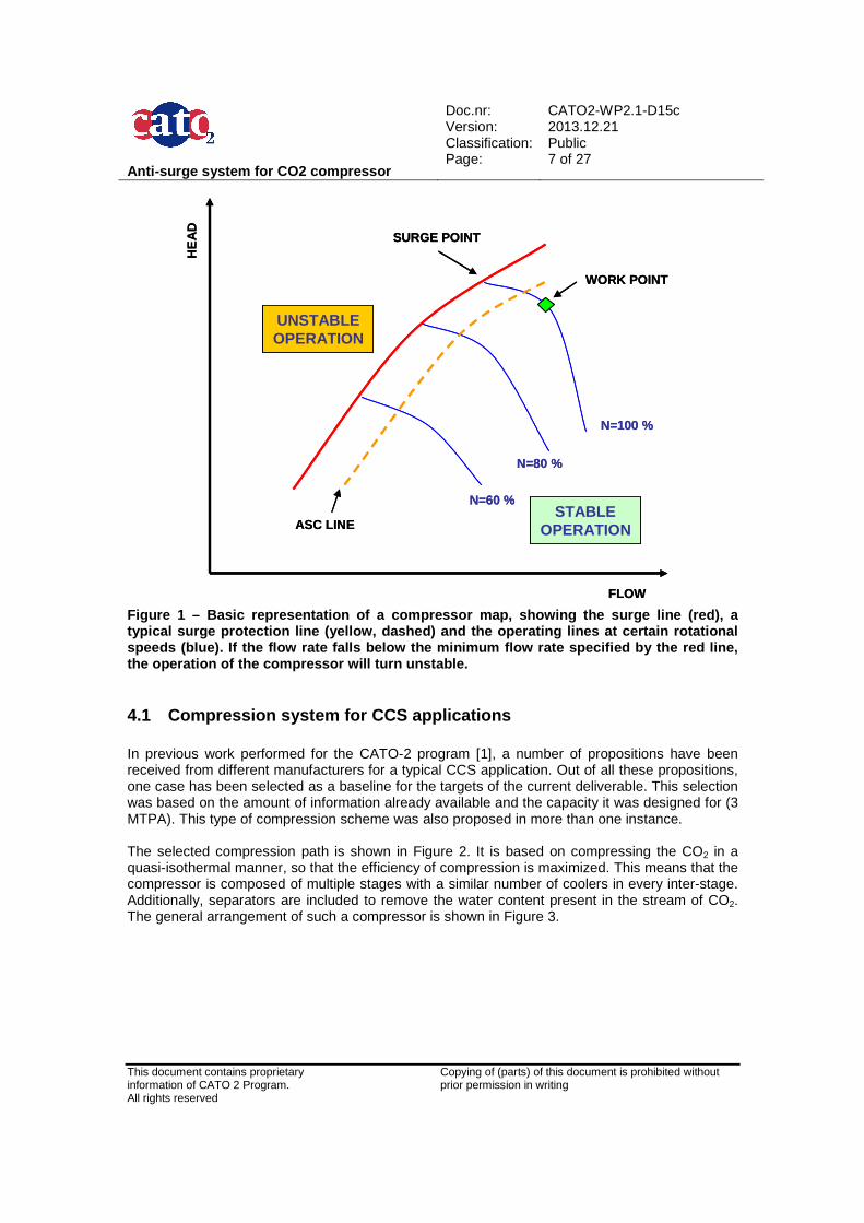
4 Introduction For any CCS system, the compressor is certainly one of the most vital components of the installation. The compressor has the mission of increasing the pressure of the CO2 gas stream, thereby increasing its density, to make it fit for delivery. A typical requirement of the compressor for this type of application consists of an overall pressure ratio of over 70 and up to 150 or higher. The economics of the system also impose a strict requirement on the power efficiency of the device. Reliability is however also major driver of some of the design choices. When the compressor is down, the full process is down. Therefore it is extremely important to ensure the integrity of the compressor at all times since the overall process depends heavily on it. There are a number of challenges for any compressor, but some of them particular to CO2 have been identified in a separate CATO deliverable [1]. Concerning the reliability, and not the performance, corrosion is probably the worst issue. This drives the need of installing separators in between different compression stages, so that any water present in the stream is removed and the life of the parts is maximized. From the operational point of view, several conditions might jeopardize the integrity of the compressor. The most challenging condition that can be imposed on the compressor is known as Emergency Shut-Down (ESD), since it can easily lead to a condition known as surge. Surge is the unstable operation of the compressor in which the resistance of the system is so high that flow reversal occurs cyclically, resulting in massive dynamic loads on the compressor. Whether or not the operating point is close to fall into surge can be told from the compressor map (see Figure 1). The compressor map represents the performance of the compressor in terms of head as a function of the flow rate and usually isolines of rotational speed. The surge line marks the final frontier for stable operation of the compressor. Surge cycles typically have a frequency of ~ 1 Hz. Surge induces loads that are so high that few surge cycles can literally destroy the compressor. Depending on the particular sensitivity of the system and the working point of the compressor, other transient phenomena could also potentially drive the compressor into surge, but it is less likely if the compressor is protected by a properly designed Anti-Surge Control (ASC) System. No compressor nowadays is delivered without an ASC system around it. The mission of the ASC is normally to prevent surge, but, due to economic reasons, it might be set to allow a limited number of surge cycles. In all cases, its primary objective is ensure the integrity of the compressor and the connected process equipment. The ASC system considers an ASC line beyond which it executes some correcting action. This line has been overlaid also in Figure 1. In the following chapters, further exploration is done on ASC systems.
Anti-surge system for CO2 compressor
Doc.nr: Version: Classification: Page:
CATO2-WP2.1-D15c 2013.12.21 Public 7 of 27
This document contains proprietary information of CATO 2 Program. All rights reserved
Copying of (parts) of this document is prohibited without prior permission in writing
N=60 %
N=80 %
N=100 %
FLOW
SURGE POINT
WORK POINT
HE
AD
STABLEOPERATION
UNSTABLEOPERATION
ASC LINE
N=60 %
N=80 %
N=100 %
FLOW
SURGE POINT
WORK POINT
HE
AD
STABLEOPERATION
UNSTABLEOPERATION
ASC LINE
Figure 1 – Basic representation of a compressor map , showing the surge line (red), a typical surge protection line (yellow, dashed) and the operating lines at certain rotational speeds (blue). If the flow rate falls below the min imum flow rate specified by the red line, the operation of the compressor will turn unstable.
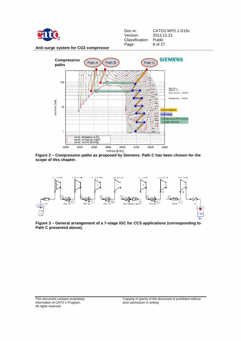
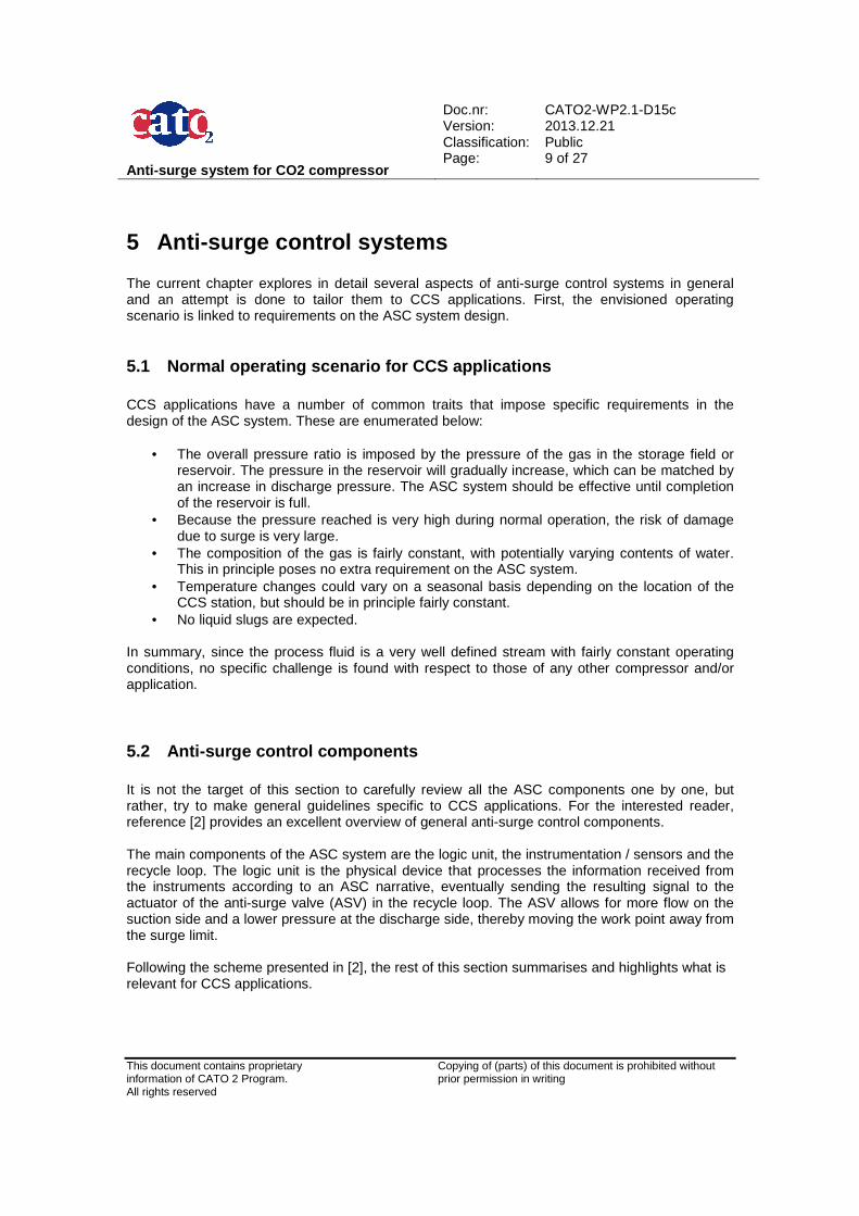
4.1 Compression system for CCS applications In previous work performed for the CATO-2 program [1], a number of propositions have been received from different manufacturers for a typical CCS application. Out of all these propositions, one case has been selected as a baseline for the targets of the current deliverable. This selection was based on the amount of information already available and the capacity it was designed for (3 MTPA). This type of compression scheme was also proposed in more than one instance. The selected compression path is shown in Figure 2. It is based on compressing the CO2 in a quasi-isothermal manner, so that the efficiency of compression is maximized. This means that the compressor is composed of multiple stages with a similar number of coolers in every inter-stage. Additionally, separators are included to remove the water content present in the stream of CO2. The general arrangement of such a compressor is shown in Figure 3.
Anti-surge system for CO2 compressor
Doc.nr: Version: Classification: Page:
CATO2-WP2.1-D15c 2013.12.21 Public 8 of 27
This document contains proprietary information of CATO 2 Program. All rights reserved
Copying of (parts) of this document is prohibited without prior permission in writing
Figure 2 – Compression paths as proposed by Siemens . Path C has been chosen for the scope of this chapter.
Figure 3 – General arrangement of a 7-stage IGC for CCS applications (corresponding to Path C presented above).
Anti-surge system for CO2 compressor
Doc.nr: Version: Classification: Page:
CATO2-WP2.1-D15c 2013.12.21 Public 9 of 27
This document contains proprietary information of CATO 2 Program. All rights reserved
Copying of (parts) of this document is prohibited without prior permission in writing
5 Anti-surge control systems The current chapter explores in detail several aspects of anti-surge control systems in general and an attempt is done to tailor them to CCS applications. First, the envisioned operating scenario is linked to requirements on the ASC system design.
5.1 Normal operating scenario for CCS applications CCS applications have a number of common traits that impose specific requirements in the design of the ASC system. These are enumerated below:
• The overall pressure ratio is imposed by the pressure of the gas in the storage field or reservoir. The pressure in the reservoir will gradually increase, which can be matched by an increase in discharge pressure. The ASC system should be effective until completion of the reservoir is full.
• Because the pressure reached is very high during normal operation, the risk of damage due to surge is very large.
• The composition of the gas is fairly constant, with potentially varying contents of water. This in principle poses no extra requirement on the ASC system.
• Temperature changes could vary on a seasonal basis depending on the location of the CCS station, but should be in principle fairly constant.
• No liquid slugs are expected. In summary, since the process fluid is a very well defined stream with fairly constant operating conditions, no specific challenge is found with respect to those of any other compressor and/or application.
5.2 Anti-surge control components It is not the target of this section to carefully review all the ASC components one by one, but rather, try to make general guidelines specific to CCS applications. For the interested reader, reference [2] provides an excellent overview of general anti-surge control components. The main components of the ASC system are the logic unit, the instrumentation / sensors and the recycle loop. The logic unit is the physical device that processes the information received from the instruments according to an ASC narrative, eventually sending the resulting signal to the actuator of the anti-surge valve (ASV) in the recycle loop. The ASV allows for more flow on the suction side and a lower pressure at the discharge side, thereby moving the work point away from the surge limit. Following the scheme presented in [2], the rest of this section summarises and highlights what is relevant for CCS applications.
Anti-surge system for CO2 compressor
Doc.nr: Version: Classification: Page:
CATO2-WP2.1-D15c 2013.12.21 Public 10 of 27
This document contains proprietary information of CATO 2 Program. All rights reserved
Copying of (parts) of this document is prohibited without prior permission in writing
5.2.1 Surge Limit Line and Margin
The surge line determines the point where the compressor will go into surge, and the surge margin, how far from this line the ASC should take correcting action. These two lines have been previously shown in Figure 1. The surge limit line for a CO2 compressor is best tested at the factory and verified on-site. It should be based on reduced representations of the head and flow, to ensure maximum accuracy even with varying contents of water present in the CO2 stream. When verification is performed on-site, industry guidelines such as [4] should be followed. The surge margin has to be chosen as the best compromise between adequate protection of the compressor and operation flexibility and efficiency. Depending on the application, the pressures and flows, and thus the work point, may vary considerably. The likelihood of the occurrence of a worst-case event such as an emergency shut-down, may require a large surge margin, with the consequence of reduced compression efficiency, and/or an expensive, very fast acting ASC and AS Valve. On the other hand, centrifugal compressors are known to be able to survive a limited number of surge cycles. Therefore the design of a ASC system implies finding a compromise between the operating conditions, the chance that an exceptional event may occur and the requirements of the ASC. In some cases it is impossible to avoid any surge cycle when an exceptional event, such as an ESD, occurs. Therefore it is good engineering practice to analyse the surge behaviour of a compressor. Compressor integrity is much more relevant than other criteria. Commonly, a surge margin of 10 % is recommended. Care should be taken in selecting appropriate hardware (ASV-actuator system) that is fast enough to respond with the surge margin selected. Sometimes a combination of a quick opening valve and a (slower) control valve is applied, in which the quick opening valve is used to cope with sudden changes. If the ASC system is too slow, a wider surge margin can be applied to avoid surge. The surge margin for multi-stage compressors (such as the one presented in 4.1) should be further adjusted to prevent one particular stage from surging and thus drive the others into surge. Unexpected failures of one stage could potentially occur even in stable operation close to surge, due to local blade stall [3]. Basically, a blade stalls when the flow can’t cope with the adverse pressure gradient, thus leading to flow separation. The wakes of separated flow impose a substantially different pressure field that can cause an adjacent blade to stall, and so this one to the following. Because of this rotating pattern of separated flow region, this phenomenon is commonly known as rotating stall.
5.2.2 Anti-surge valve
The ASV is of paramount importance when it comes to evaluate the performance of the surge protection system. Many design choices have to be considered:
• The ASV minimum opening time has to be short enough to protect the compressor in the event of an ESD. Its capacity should be also sufficient to reduce the compressor backpressure in this event.
• Depending on the operation environment, the ASV can have competing requirements leading to multiple-valve systems. Single-valve systems are however more cost-effective and therefore a requirement for the economic viability of a CCS station. A compromise is recommended based on the selection of a very fast response valve, whose capacity is matched to the compressor and the volume on the discharge side, with an equal percentage characteristic. Appropriate modelling of the system and its transient response in all potentially dangerous scenarios seems a necessity to judge the performance of the ASV.
Anti-surge system for CO2 compressor
Doc.nr: Version: Classification: Page:
CATO2-WP2.1-D15c 2013.12.21 Public 11 of 27
This document contains proprietary information of CATO 2 Program. All rights reserved
Copying of (parts) of this document is prohibited without prior permission in writing
• The recycle system should be designed to account for a potentially severe Joule-Thomson effect. It is recommended to trace the AS line if necessary to control the temperature and avoid CO2 phase changes. Appendix A contains calculations applicable to the baseline case selected for this document.
5.2.3 Instrumentation
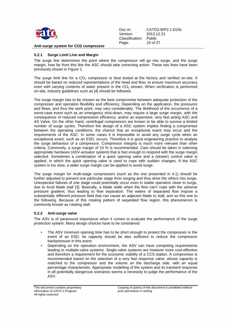
The ASC logic unit is provided with signals obtained by sensors in the system, eventually sending a correcting signal (or not) to the actuating system/ASV. An example of instrumentation location around the compressor is provided in Figure 4.
• A flow meter of an appropriate type needs to be in place for comparison of the actual flow rate compared to the surge flow rate. A device installed at the impeller’s eye is recommended for early incipient surge detection [5].
• Pressure and temperature sensors have to be installed at suction and discharge side of the compressor to determine the actual head. A factor to consider is the time constant, which should be one order of magnitude better than the system requirements.
• There are a number of sources that can lead to inaccurate sensor measurements. One of the most important ones for CCS application is the equation of state used by the control algorithm. Significant deviations are found for CO2 at high pressure when using different equations of state [7]. Using a “reduced head vs reduced flow rate” representation of the performance can reduce such an uncertainty, because the magnitudes sensitive to the chosen EOS apply to both head and flow and thus cancel each other out. The uncertainties shown in Table 1 are recommended to be taken into account.
COMPRESSOR
LOGIC UNIT
TT FT PT TTPT
ASV
COMPRESSORCOMPRESSOR
LOGIC UNIT
TT FT PT TTPT
ASV
Figure 4 – Basic representation of the compressor, the recycle loop and the location for the flow (FT), temperature (TT) and pressure transducers (PT).
Table 1 – Recommended uncertainties to consider for the AS instrumentation, as proposed in [2].
Measurement Recommended Accuracy
Pressure 0.3 – 2 % at full scale
Temperature 0.3 – 4.0 °C
Flow 1.0 – 3 %
Anti-surge system for CO2 compressor
Doc.nr: Version: Classification: Page:
CATO2-WP2.1-D15c 2013.12.21 Public 12 of 27
This document contains proprietary information of CATO 2 Program. All rights reserved
Copying of (parts) of this document is prohibited without prior permission in writing
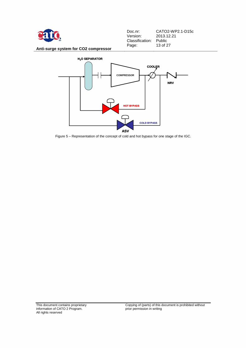
6 Anti-surge system layout In this chapter, possible layouts for the compressor presented in chapter 4 are considered. In the selection of the anti-surge system layout, there are mainly two degrees of freedom. The first one is the number of loops and their tie-in points. The second one is the choice for cold or hot gas in the recycle line (see Figure 5). Ideally every stage would have a recycle loop around it, so that every stage has independent surge protection. This however can be very costly and difficult to implement in practice, especially for a fully integrated geared compressor. The alternative is installing loops at the stage that is most sensitive for surge. Additional controls can be installed for suction temperatures to avoid dramatic compressibility variations. The inter-stage coolers should also be regulated. A system similar to the one used as baseline case in this document is described in [6]. Regarding the specific configuration of each loop, a non-return valve (NRV) has to be present right downstream of the recycle loop to minimize the volume of gas that needs to be recycled. This is for every choice of layout. It is also recommended that the tie-in point on the suction side is upstream of the compressor flow measurement device. The following general facts lead to guidelines about the arrangement of the AS system. It is strongly advised to confirm these by means of modelling.
• During a shut-down event, the flow rate decreases so rapidly that there is a big chance of running into surge. Hence, it is recommended to reduce the head and increase the flow as quickly as possible by means of minimization of the discharge volume. The discharge volume consists of the volume of all piping in between the check valve, the compressor and the ASV. So the NRV should be close to the compressor discharge flange, and all vessels with water separation should be placed in the suction side.
• During start-up, the gas is continuously recycled leading potentially to overheating. To allow for more time to get the compressor up to speed, larger volumes are beneficial. To make this compatible with the previous point, cooling can be installed in the hot recycle line.
• When a single loop is used for two or multiple stages, a certain level of risk is assumed that the ASV will not be able to prevent one stage to surge and drive the rest into it. It is therefore recommended to carefully check the performance of the system by means of simulation.
Anti-surge system for CO2 compressor
Doc.nr: Version: Classification: Page:
CATO2-WP2.1-D15c 2013.12.21 Public 13 of 27
This document contains proprietary information of CATO 2 Program. All rights reserved
Copying of (parts) of this document is prohibited without prior permission in writing
COMPRESSOR
ASV
COLD BYPASS
HOT BYPASS
NRV
COOLER
H2O SEPARATOR
COMPRESSORCOMPRESSOR
ASV
COLD BYPASS
HOT BYPASS
NRV
COOLER
H2O SEPARATOR
Figure 5 – Representation of the concept of cold and hot bypass for one stage of the IGC.
Anti-surge system for CO2 compressor
Doc.nr: Version: Classification: Page:
CATO2-WP2.1-D15c 2013.12.21 Public 14 of 27
This document contains proprietary information of CATO 2 Program. All rights reserved
Copying of (parts) of this document is prohibited without prior permission in writing
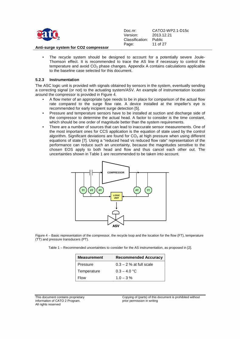
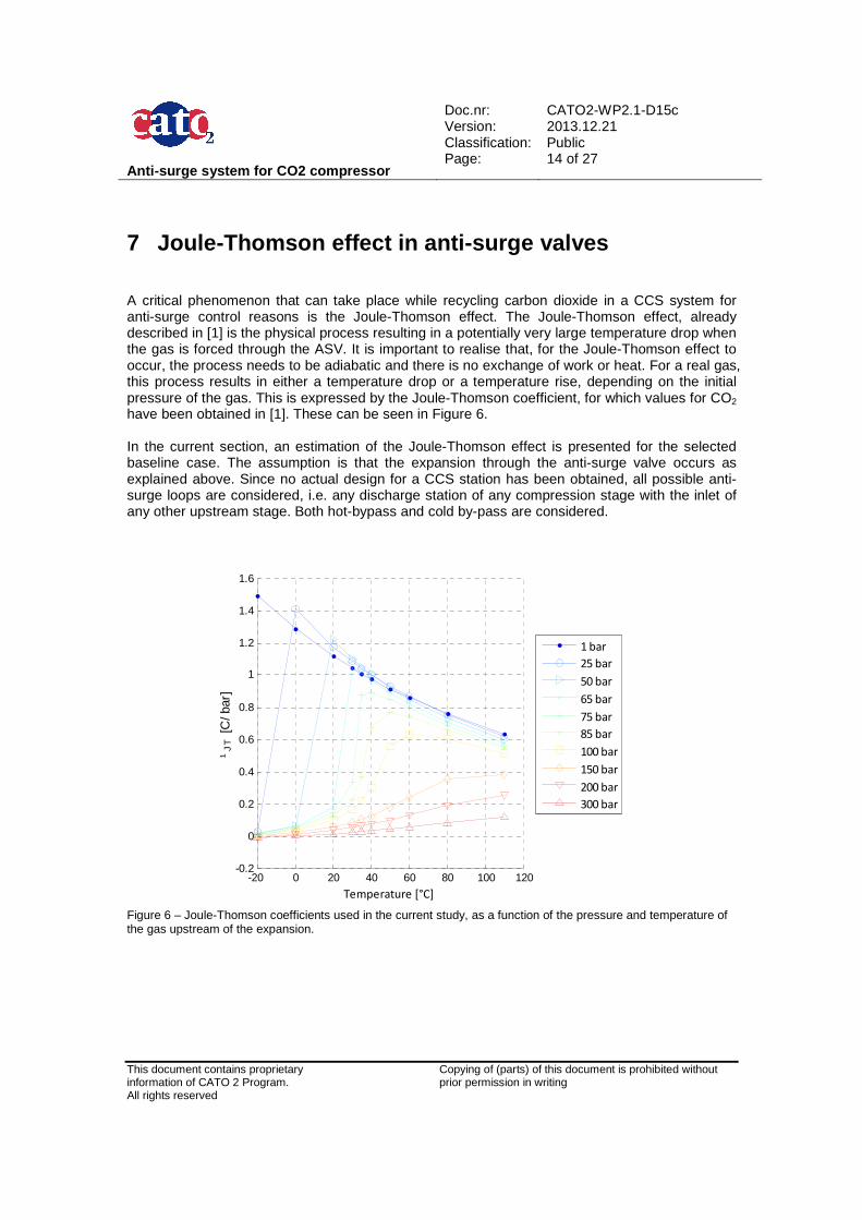
7 Joule-Thomson effect in anti-surge valves A critical phenomenon that can take place while recycling carbon dioxide in a CCS system for anti-surge control reasons is the Joule-Thomson effect. The Joule-Thomson effect, already described in [1] is the physical process resulting in a potentially very large temperature drop when the gas is forced through the ASV. It is important to realise that, for the Joule-Thomson effect to occur, the process needs to be adiabatic and there is no exchange of work or heat. For a real gas, this process results in either a temperature drop or a temperature rise, depending on the initial pressure of the gas. This is expressed by the Joule-Thomson coefficient, for which values for CO2 have been obtained in [1]. These can be seen in Figure 6. In the current section, an estimation of the Joule-Thomson effect is presented for the selected baseline case. The assumption is that the expansion through the anti-surge valve occurs as explained above. Since no actual design for a CCS station has been obtained, all possible anti-surge loops are considered, i.e. any discharge station of any compression stage with the inlet of any other upstream stage. Both hot-bypass and cold by-pass are considered.
-20 0 20 40 60 80 100 120-0.2
0
0.2
0.4
0.6
0.8
1
1.2
1.4
1.6
Temperature [°C]
¹ JT
[C/b
ar]
1 bar
25 bar
50 bar
65 bar
75 bar
85 bar
100 bar
150 bar
200 bar
300 bar
Figure 6 – Joule-Thomson coefficients used in the current study, as a function of the pressure and temperature of the gas upstream of the expansion.
Anti-surge system for CO2 compressor
Doc.nr: Version: Classification: Page:
CATO2-WP2.1-D15c 2013.12.21 Public 15 of 27
This document contains proprietary information of CATO 2 Program. All rights reserved
Copying of (parts) of this document is prohibited without prior permission in writing
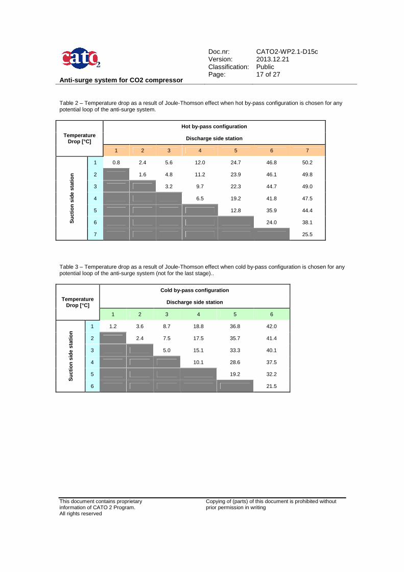
Table 2 and Table 3 collect the results of temperature drop due to the Joule-Thomson effect. The following observations can be made:
• A cold-bypass configuration always results in a stronger cooling effect due to Joule-Thomson effect in the ASV, unless the pressure is sufficiently high.
• The maximum cooling found for the baseline case corresponds to a temperature drop of approximately 50 °C. This would occur when connecting the hot stream of the discharge of the last stage with the low-pressure inlet station of the first stage.
• Because of the high temperatures of the gas right at the discharge of any compression stage, none of the hot by-pass configurations presented here seem to have a potential risk of phase change.
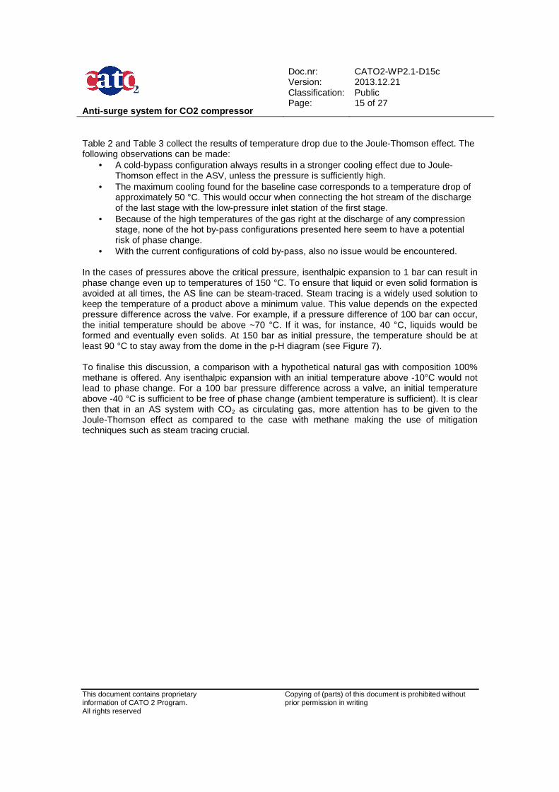
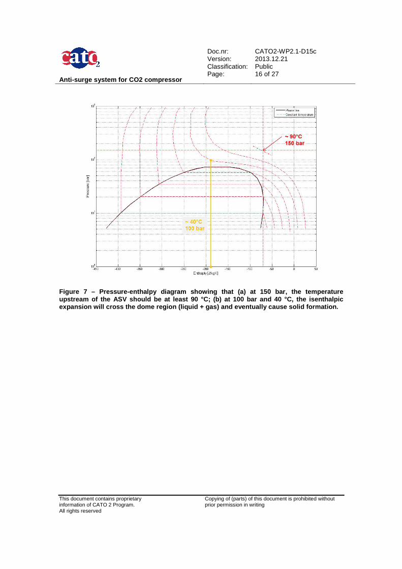
• With the current configurations of cold by-pass, also no issue would be encountered. In the cases of pressures above the critical pressure, isenthalpic expansion to 1 bar can result in phase change even up to temperatures of 150 °C. To ensure that liquid or even solid formation is avoided at all times, the AS line can be steam-traced. Steam tracing is a widely used solution to keep the temperature of a product above a minimum value. This value depends on the expected pressure difference across the valve. For example, if a pressure difference of 100 bar can occur, the initial temperature should be above ~70 °C. If it was, for instance, 40 °C, liquids would be formed and eventually even solids. At 150 bar as initial pressure, the temperature should be at least 90 °C to stay away from the dome in the p-H diagram (see Figure 7). To finalise this discussion, a comparison with a hypothetical natural gas with composition 100% methane is offered. Any isenthalpic expansion with an initial temperature above -10°C would not lead to phase change. For a 100 bar pressure difference across a valve, an initial temperature above -40 °C is sufficient to be free of phase change (ambient temperature is sufficient). It is clear then that in an AS system with CO2 as circulating gas, more attention has to be given to the Joule-Thomson effect as compared to the case with methane making the use of mitigation techniques such as steam tracing crucial.
Anti-surge system for CO2 compressor
Doc.nr: Version: Classification: Page:
CATO2-WP2.1-D15c 2013.12.21 Public 16 of 27
This document contains proprietary information of CATO 2 Program. All rights reserved
Copying of (parts) of this document is prohibited without prior permission in writing
Figure 7 – Pressure-enthalpy diagram showing that ( a) at 150 bar, the temperature upstream of the ASV should be at least 90 °C; (b) a t 100 bar and 40 °C, the isenthalpic expansion will cross the dome region (liquid + gas) and eventually cause solid formation.
Anti-surge system for CO2 compressor
Doc.nr: Version: Classification: Page:
CATO2-WP2.1-D15c 2013.12.21 Public 17 of 27
This document contains proprietary information of CATO 2 Program. All rights reserved
Copying of (parts) of this document is prohibited without prior permission in writing
Table 2 – Temperature drop as a result of Joule-Thomson effect when hot by-pass configuration is chosen for any potential loop of the anti-surge system.
Temperature Drop [°C]
Hot by-pass configuration
Discharge side station
1 2 3 4 5 6 7
Suc
tion
side
sta
tion
1 0.8 2.4 5.6 12.0 24.7 46.8 50.2
2 1.6 4.8 11.2 23.9 46.1 49.8
3 3.2 9.7 22.3 44.7 49.0
4 6.5 19.2 41.8 47.5
5 12.8 35.9 44.4
6 24.0 38.1
7 25.5
Table 3 – Temperature drop as a result of Joule-Thomson effect when cold by-pass configuration is chosen for any potential loop of the anti-surge system (not for the last stage)..
Temperature Drop [°C]
Cold by-pass configuration
Discharge side station
1 2 3 4 5 6
Suc
tion
side
sta
tion
1 1.2 3.6 8.7 18.8 36.8 42.0
2 2.4 7.5 17.5 35.7 41.4
3 5.0 15.1 33.3 40.1
4 10.1 28.6 37.5
5 19.2 32.2
6 21.5
Anti-surge system for CO2 compressor
Doc.nr: Version: Classification: Page:
CATO2-WP2.1-D15c 2013.12.21 Public 18 of 27
This document contains proprietary information of CATO 2 Program. All rights reserved
Copying of (parts) of this document is prohibited without prior permission in writing
8 System Dynamics Simulations for ASC evaluation It has been stated in several occasions on this report that modelling of a particular system is strongly recommended to evaluate the performance of its ASC system. Unfortunately, no CCS detailed design has been available at the time of the present study, neither the design of the compressor nor the general system layout. However, preliminary design of the main parts has been performed with the knowledge and tools available at the moment. This appendix contains first general information regarding system dynamic simulations followed by the results of the preliminary design for the compressor.
8.1 General information System Dynamics Simulations Simulation plays an important role both in the analysis of transient operations (e.g. shutdown) and the evaluation of process dynamics at steady-state operating conditions (e.g. stability and controllability). These so-called System Dynamics Simulations can be applied for a number of examples, including:
• System lay out and equipment selection. • Process control and safeguarding. • Plant availability. • Process stability (e.g. limit cycling, surge). • Dynamic operating procedures.(e.g. start-up, emergency shutdown or variation of feed
gas composition). • Trip response of (instrumented) safeguarding actions as defined in the cause and effect
diagrams (e.g. response of a HIPPS system). • The effect of failure on demand of (instrumented) safeguarding functions during
emergency situations (e.g. failure modes relating to ESD valves, depressurisation valves or instrument malfunction).
• The effect of revealed failures such as a spurious trip of single piece of rotating or static equipment, a valve or an instrument.
This is realised by simulating the dynamic behaviour of flow in the pipe system, flow lines, process equipment (e.g. separators, furnaces), fluid machinery (e.g. compressors, pumps, turbines) and process control functionality. Current software capabilities allow for analyses involving:
• Mass, impulse and energy balances. • Heat transfer between the fluid flow, the pipe of duct wall and the environment. • Tracking of composition variations of process flows. • Process controllers, anti-surge control, control valves and safety valves. • Fluid machinery, including controllable inlet guide vanes, speed control and rotor inertia. • Furnaces with (sub)stoichiometric combustion.
8.2 Preliminary design of the system This section presents the results obtained for the preliminary design of the compressor. The same information as provided to the manufacturers for their proposition [1] was used as input for
Anti-surge system for CO2 compressor
Doc.nr: Version: Classification: Page:
CATO2-WP2.1-D15c 2013.12.21 Public 19 of 27
This document contains proprietary information of CATO 2 Program. All rights reserved
Copying of (parts) of this document is prohibited without prior permission in writing
the current design. The compression path however is assumed to follow that described in chapter 4. The tool to perform the preliminary design of the compressor is CompAero, which is a suite of centrifugal and axial-flow compressor aerodynamic design and analysis programs. The following factors have been used in the preliminary design of the compressor:
• The compressor designed assumes an IGC type – i.e. every stage can have a different rotational speed.
• Every stage is composed of a single shrouded wheel or impeller with no splitter blades. • The pressure ratio across each stage at the design point is the same, in this case, 2.02. • The Mach number at the inlet of each stage has been assumed lower than 0.3 to safely
assume that static and stagnation conditions are very similar. • The philosophy followed regarding the compromise between rotational and impeller
diameter has been to maximize the rotational speed without reaching supersonic speed at any point of the impeller.
• The circulating fluid is CO2, assumed dry for the sake of simplicity, whose conditions are calculated according to Aungier’s modified Redlich-Kwong EOS.
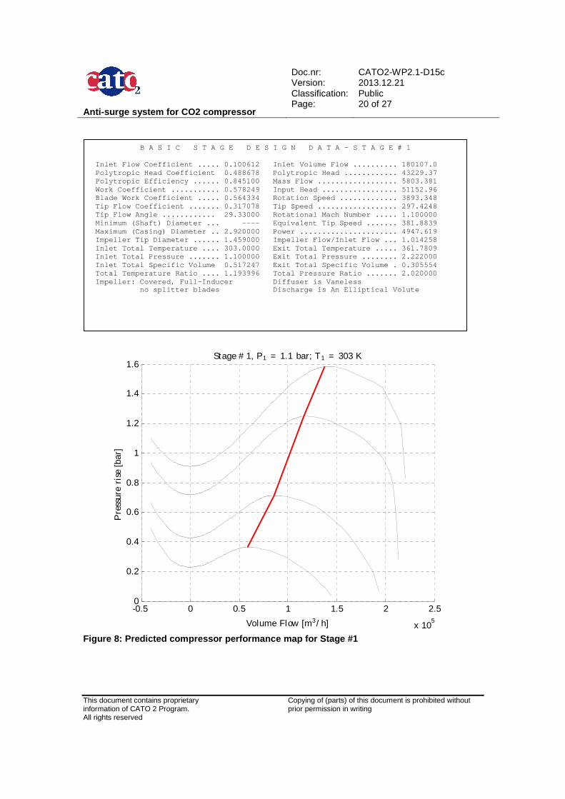
The results for each of the seven stages of this compressor are shown in subsequent pages. Once the compressor is designed, the compressor performance maps can be calculated (shown below in one figure per stage). These maps are a fundamental input for a dynamic simulation.
Anti-surge system for CO2 compressor
Doc.nr: Version: Classification: Page:
CATO2-WP2.1-D15c 2013.12.21 Public 20 of 27
This document contains proprietary information of CATO 2 Program. All rights reserved
Copying of (parts) of this document is prohibited without prior permission in writing
-0.5 0 0.5 1 1.5 2 2.5
x 105
0
0.2
0.4
0.6
0.8
1
1.2
1.4
1.6Stage # 1, P1 = 1.1 bar; T1 = 303 K
Volume Flow [m3/ h]
Pre
ssur
eri
se[b
ar]
Figure 8: Predicted compressor performance map for Stage #1
B A S I C S T A G E D E S I G N D A T A – S T A G E # 1 Inlet Flow Coefficient ..... 0.100612 Inlet Volu me Flow .......... 180107.0 Polytropic Head Coefficient 0.488678 Polytropic Head ............ 43229.37 Polytropic Efficiency ...... 0.845100 Mass Flow .................. 5803.381 Work Coefficient ........... 0.578249 Input Head ................. 51152.96 Blade Work Coefficient ..... 0.564334 Rotation S peed ............. 3893.348 Tip Flow Coefficient ....... 0.317078 Tip Speed .................. 297.4248 Tip Flow Angle ............ 29.33000 Rotational Mach Number ..... 1.100000 Minimum (Shaft) Diameter ... ---- Equivalent Tip Speed ....... 381.8839 Maximum (Casing) Diameter .. 2.920000 Power .... .................. 4947.619 Impeller Tip Diameter ...... 1.459000 Impeller F low/Inlet Flow ... 1.014258 Inlet Total Temperature .... 303.0000 Exit Total Temperature ..... 361.7809 Inlet Total Pressure ....... 1.100000 Exit Total Pressure ........ 2.222000 Inlet Total Specific Volume 0.517247 Exit Total Specific Volume . 0.305554 Total Temperature Ratio .... 1.193996 Total Pres sure Ratio ....... 2.020000 Impeller: Covered, Full-Inducer Diffuser i s Vaneless no splitter blades Discharge is An Elliptical Volute
Anti-surge system for CO2 compressor
Doc.nr: Version: Classification: Page:
CATO2-WP2.1-D15c 2013.12.21 Public 21 of 27
This document contains proprietary information of CATO 2 Program. All rights reserved
Copying of (parts) of this document is prohibited without prior permission in writing
-4 -2 0 2 4 6 8 10
x 104
0
0.5
1
1.5
2
2.5
3
3.5
4Stage # 2, P1 = 2.22 bar; T1 = 305 K
Volume Flow [m3/ h]
Pre
ssur
eri
se[b
ar]
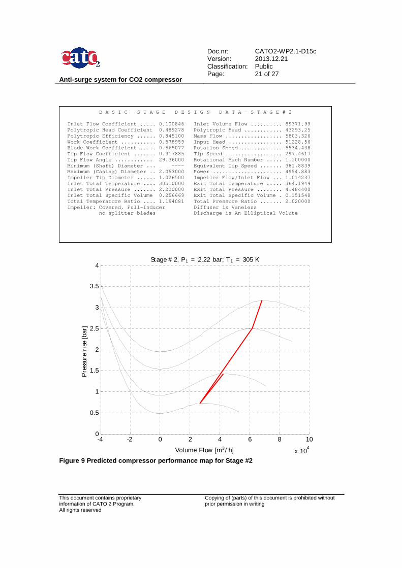
Figure 9 Predicted compressor performance map for S tage #2
B A S I C S T A G E D E S I G N D A T A – S T A G E # 2 Inlet Flow Coefficient ..... 0.100846 Inlet Volu me Flow .......... 89371.99 Polytropic Head Coefficient 0.489278 Polytropic Head ............ 43293.25 Polytropic Efficiency ...... 0.845100 Mass Flow .................. 5803.326 Work Coefficient ........... 0.578959 Input Head ................. 51228.56 Blade Work Coefficient ..... 0.565077 Rotation S peed ............. 5534.438 Tip Flow Coefficient ....... 0.317885 Tip Speed .................. 297.4617 Tip Flow Angle ............ 29.36000 Rotational Mach Number ..... 1.100000 Minimum (Shaft) Diameter ... ---- Equivalent Tip Speed ....... 381.8839 Maximum (Casing) Diameter .. 2.053000 Power .... .................. 4954.883 Impeller Tip Diameter ...... 1.026500 Impeller F low/Inlet Flow ... 1.014237 Inlet Total Temperature .... 305.0000 Exit Total Temperature ..... 364.1949 Inlet Total Pressure ....... 2.220000 Exit Total Pressure ........ 4.484400 Inlet Total Specific Volume 0.256669 Exit Total Specific Volume . 0.151548 Total Temperature Ratio .... 1.194081 Total Pres sure Ratio ....... 2.020000 Impeller: Covered, Full-Inducer Diffuser i s Vaneless no splitter blades Discharge is An Elliptical Volute
Anti-surge system for CO2 compressor
Doc.nr: Version: Classification: Page:
CATO2-WP2.1-D15c 2013.12.21 Public 22 of 27
This document contains proprietary information of CATO 2 Program. All rights reserved
Copying of (parts) of this document is prohibited without prior permission in writing
-1 0 1 2 3 4 5
x 104
0
1
2
3
4
5
6Stage # 3, P1 = 4.48 bar; T1 = 305 K
Volume Flow [m3/ h]
Pre
ssur
eri
se[b
ar]
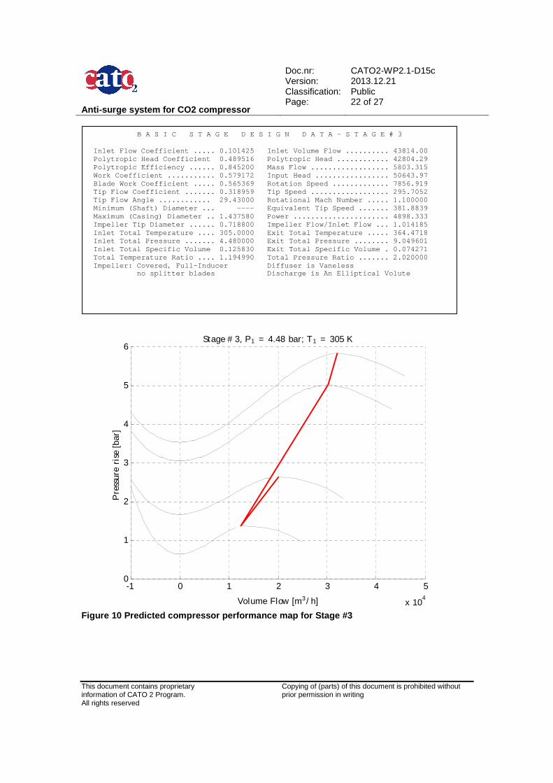
Figure 10 Predicted compressor performance map for Stage #3
B A S I C S T A G E D E S I G N D A T A – S T A G E # 3 Inlet Flow Coefficient ..... 0.101425 Inlet Volu me Flow .......... 43814.00 Polytropic Head Coefficient 0.489516 Polytropic Head ............ 42804.29 Polytropic Efficiency ...... 0.845200 Mass Flow .................. 5803.315 Work Coefficient ........... 0.579172 Input Head ................. 50643.97 Blade Work Coefficient ..... 0.565369 Rotation S peed ............. 7856.919 Tip Flow Coefficient ....... 0.318959 Tip Speed .................. 295.7052 Tip Flow Angle ............ 29.43000 Rotational Mach Number ..... 1.100000 Minimum (Shaft) Diameter ... ---- Equivalent Tip Speed ....... 381.8839 Maximum (Casing) Diameter .. 1.437580 Power .... .................. 4898.333 Impeller Tip Diameter ...... 0.718800 Impeller F low/Inlet Flow ... 1.014185 Inlet Total Temperature .... 305.0000 Exit Total Temperature ..... 364.4718 Inlet Total Pressure ....... 4.480000 Exit Total Pressure ........ 9.049601 Inlet Total Specific Volume 0.125830 Exit Total Specific Volume . 0.074271 Total Temperature Ratio .... 1.194990 Total Pres sure Ratio ....... 2.020000 Impeller: Covered, Full-Inducer Diffuser i s Vaneless no splitter blades Discharge is An Elliptical Volute
Anti-surge system for CO2 compressor
Doc.nr: Version: Classification: Page:
CATO2-WP2.1-D15c 2013.12.21 Public 23 of 27
This document contains proprietary information of CATO 2 Program. All rights reserved
Copying of (parts) of this document is prohibited without prior permission in writing
-1 -0.5 0 0.5 1 1.5 2 2.5
x 104
0
2
4
6
8
10
12
14
16Stage # 4, P1 = 9.0 bar; T1 = 305 K
Volume Flow [m3/ h]
Pre
ssur
eri
se[b
ar]
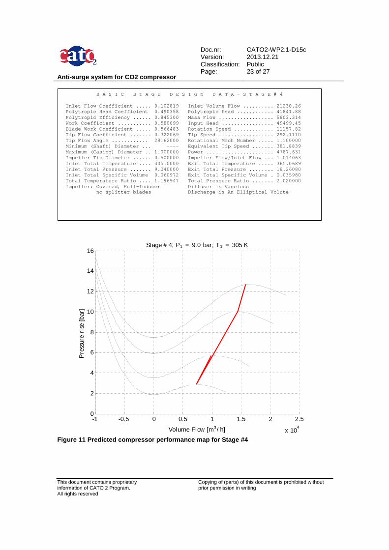
Figure 11 Predicted compressor performance map for Stage #4
B A S I C S T A G E D E S I G N D A T A – S T A G E # 4 Inlet Flow Coefficient ..... 0.102819 Inlet Volu me Flow .......... 21230.26 Polytropic Head Coefficient 0.490358 Polytropic Head ............ 41841.88 Polytropic Efficiency ...... 0.845300 Mass Flow .................. 5803.314 Work Coefficient ........... 0.580099 Input Head ................. 49499.45 Blade Work Coefficient ..... 0.566483 Rotation S peed ............. 11157.82 Tip Flow Coefficient ....... 0.322069 Tip Speed .................. 292.1110 Tip Flow Angle ............ 29.62000 Rotational Mach Number ..... 1.100000 Minimum (Shaft) Diameter ... ---- Equivalent Tip Speed ....... 381.8839 Maximum (Casing) Diameter .. 1.000000 Power .... .................. 4787.631 Impeller Tip Diameter ...... 0.500000 Impeller F low/Inlet Flow ... 1.014063 Inlet Total Temperature .... 305.0000 Exit Total Temperature ..... 365.0689 Inlet Total Pressure ....... 9.040000 Exit Total Pressure ........ 18.26080 Inlet Total Specific Volume 0.060972 Exit Total Specific Volume . 0.035980 Total Temperature Ratio .... 1.196947 Total Pres sure Ratio ....... 2.020000 Impeller: Covered, Full-Inducer Diffuser i s Vaneless no splitter blades Discharge is An Elliptical Volute
Anti-surge system for CO2 compressor
Doc.nr: Version: Classification: Page:
CATO2-WP2.1-D15c 2013.12.21 Public 24 of 27
This document contains proprietary information of CATO 2 Program. All rights reserved
Copying of (parts) of this document is prohibited without prior permission in writing
-6000 -4000 -2000 0 2000 4000 6000 8000 10000 120000
5
10
15
20
25
30
35Stage # 5, P1 = 18.2 bar; T1 = 305 K
Volume Flow [m3/ h]
Pre
ssur
eri
se[b
ar]
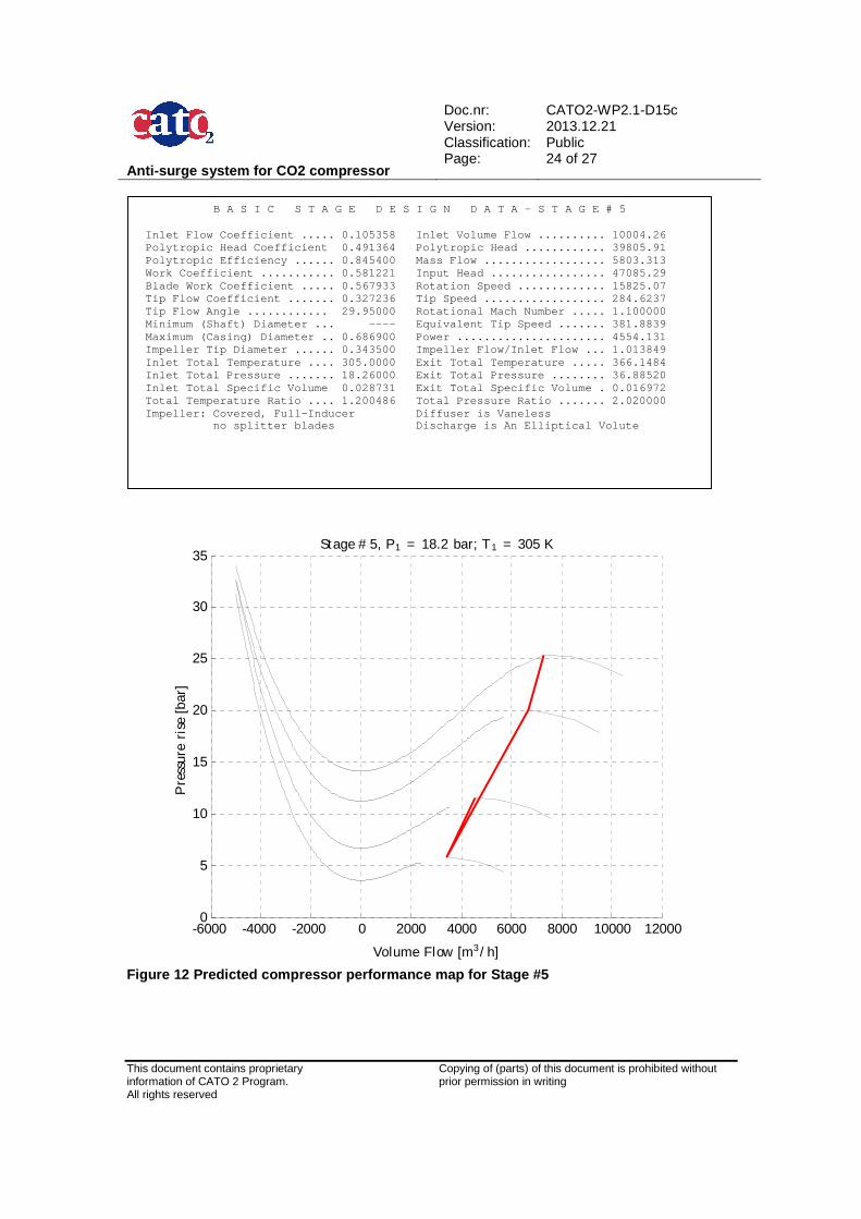
Figure 12 Predicted compressor performance map for Stage #5
B A S I C S T A G E D E S I G N D A T A – S T A G E # 5 Inlet Flow Coefficient ..... 0.105358 Inlet Volu me Flow .......... 10004.26 Polytropic Head Coefficient 0.491364 Polytropic Head ............ 39805.91 Polytropic Efficiency ...... 0.845400 Mass Flow .................. 5803.313 Work Coefficient ........... 0.581221 Input Head ................. 47085.29 Blade Work Coefficient ..... 0.567933 Rotation S peed ............. 15825.07 Tip Flow Coefficient ....... 0.327236 Tip Speed .................. 284.6237 Tip Flow Angle ............ 29.95000 Rotational Mach Number ..... 1.100000 Minimum (Shaft) Diameter ... ---- Equivalent Tip Speed ....... 381.8839 Maximum (Casing) Diameter .. 0.686900 Power .... .................. 4554.131 Impeller Tip Diameter ...... 0.343500 Impeller F low/Inlet Flow ... 1.013849 Inlet Total Temperature .... 305.0000 Exit Total Temperature ..... 366.1484 Inlet Total Pressure ....... 18.26000 Exit Total Pressure ........ 36.88520 Inlet Total Specific Volume 0.028731 Exit Total Specific Volume . 0.016972 Total Temperature Ratio .... 1.200486 Total Pres sure Ratio ....... 2.020000 Impeller: Covered, Full-Inducer Diffuser i s Vaneless no splitter blades Discharge is An Elliptical Volute
Anti-surge system for CO2 compressor
Doc.nr: Version: Classification: Page:
CATO2-WP2.1-D15c 2013.12.21 Public 25 of 27
This document contains proprietary information of CATO 2 Program. All rights reserved
Copying of (parts) of this document is prohibited without prior permission in writing
-2000 -1000 0 1000 2000 3000 4000 50000
10
20
30
40
50
60
70Stage # 6, P1 = 36.9 bar; T1 = 305 K
Volume Flow [m3/ h]
Pre
ssur
eri
se[b
ar]
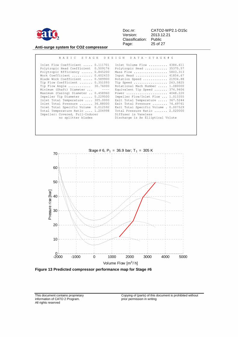
Figure 13 Predicted compressor performance map for Stage #6
B A S I C S T A G E D E S I G N D A T A – S T A G E # 6 Inlet Flow Coefficient ..... 0.111701 Inlet Volu me Flow .......... 4384.611 Polytropic Head Coefficient 0.509176 Polytropic Head ............ 35375.57 Polytropic Efficiency ...... 0.845200 Mass Flow .................. 5803.313 Work Coefficient ........... 0.602433 Input Head ................. 41854.67 Blade Work Coefficient ..... 0.589900 Rotation S peed ............. 21934.88 Tip Flow Coefficient ....... 0.351093 Tip Speed .................. 263.5825 Tip Flow Angle ............ 30.76000 Rotational Mach Number ..... 1.080000 Minimum (Shaft) Diameter ... ---- Equivalent Tip Speed ....... 374.9406 Maximum (Casing) Diameter .. 0.458960 Power .... .................. 4048.220 Impeller Tip Diameter ...... 0.229500 Impeller F low/Inlet Flow ... 1.013355 Inlet Total Temperature .... 305.0000 Exit Total Temperature ..... 367.5244 Inlet Total Pressure ....... 36.88000 Exit Total Pressure ........ 74.49761 Inlet Total Specific Volume 0.012592 Exit Total Specific Volume . 0.007529 Total Temperature Ratio .... 1.204998 Total Pres sure Ratio ....... 2.020000 Impeller: Covered, Full-Inducer Diffuser i s Vaneless no splitter blades Discharge is An Elliptical Volute
Anti-surge system for CO2 compressor
Doc.nr: Version: Classification: Page:
CATO2-WP2.1-D15c 2013.12.21 Public 26 of 27
This document contains proprietary information of CATO 2 Program. All rights reserved
Copying of (parts) of this document is prohibited without prior permission in writing
-1000 -500 0 500 1000 1500 2000 2500 3000 35000
10
20
30
40
50
60
70
80Stage # 7, P1 = 74.5 bar; T1 = 368 K
Volume Flow [m3/ h]
Pre
ssur
eri
se[b
ar]
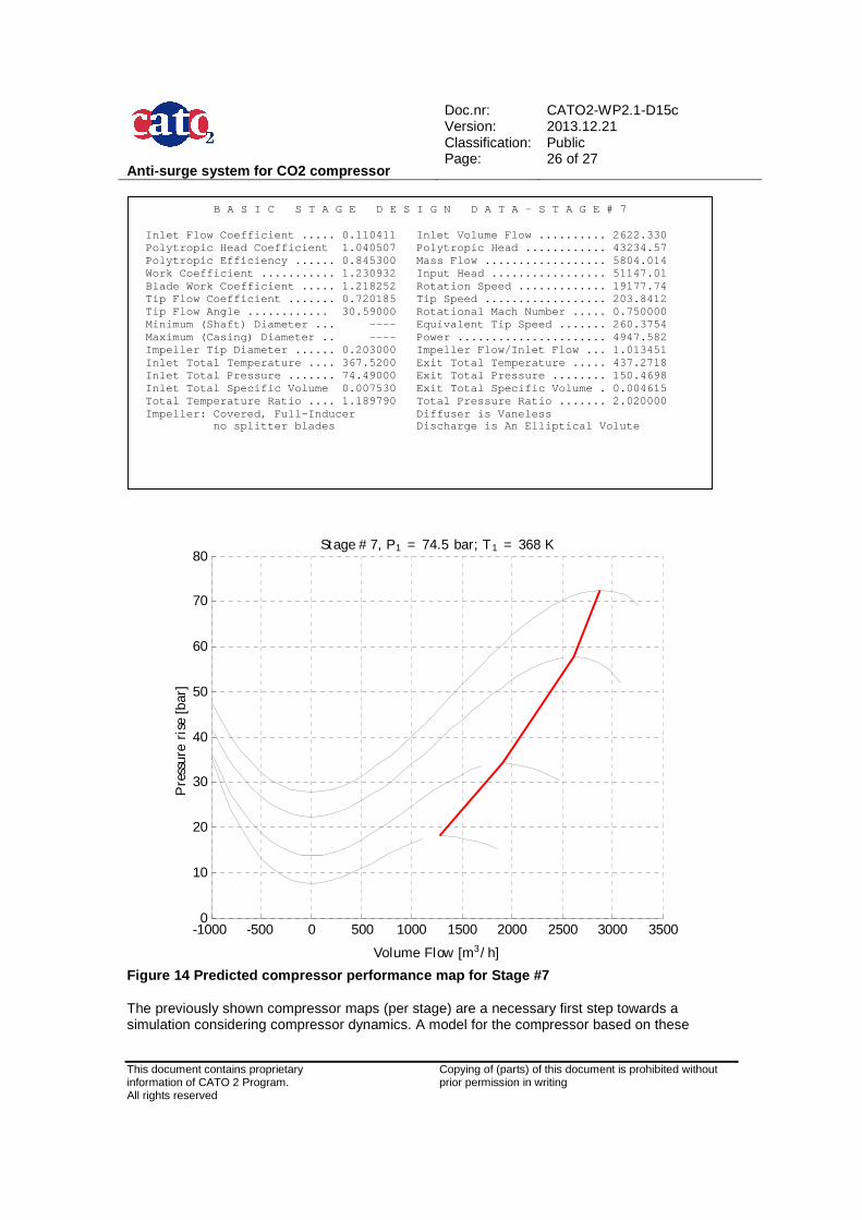
Figure 14 Predicted compressor performance map for Stage #7 The previously shown compressor maps (per stage) are a necessary first step towards a simulation considering compressor dynamics. A model for the compressor based on these
B A S I C S T A G E D E S I G N D A T A – S T A G E # 7 Inlet Flow Coefficient ..... 0.110411 Inlet Volu me Flow .......... 2622.330 Polytropic Head Coefficient 1.040507 Polytropic Head ............ 43234.57 Polytropic Efficiency ...... 0.845300 Mass Flow .................. 5804.014 Work Coefficient ........... 1.230932 Input Head ................. 51147.01 Blade Work Coefficient ..... 1.218252 Rotation S peed ............. 19177.74 Tip Flow Coefficient ....... 0.720185 Tip Speed .................. 203.8412 Tip Flow Angle ............ 30.59000 Rotational Mach Number ..... 0.750000 Minimum (Shaft) Diameter ... ---- Equivalent Tip Speed ....... 260.3754 Maximum (Casing) Diameter .. ---- Power .... .................. 4947.582 Impeller Tip Diameter ...... 0.203000 Impeller F low/Inlet Flow ... 1.013451 Inlet Total Temperature .... 367.5200 Exit Total Temperature ..... 437.2718 Inlet Total Pressure ....... 74.49000 Exit Total Pressure ........ 150.4698 Inlet Total Specific Volume 0.007530 Exit Total Specific Volume . 0.004615 Total Temperature Ratio .... 1.189790 Total Pres sure Ratio ....... 2.020000 Impeller: Covered, Full-Inducer Diffuser i s Vaneless no splitter blades Discharge is An Elliptical Volute
Anti-surge system for CO2 compressor
Doc.nr: Version: Classification: Page:
CATO2-WP2.1-D15c 2013.12.21 Public 27 of 27
This document contains proprietary information of CATO 2 Program. All rights reserved
Copying of (parts) of this document is prohibited without prior permission in writing
performance curves and a model for a pipeline system can be combined to further study likelihood of surge to occur. In this respect, the analysis would be no different than that performed for a natural gas transport system. In essence, the design of a compressor anti surge system for CO2 therefore does not constitute a specific challenge.
9 Conclusions
In this report, a close look has been given at the specific issues expected during surge of a CO2 compressor system. guidelines on the design of the anti-surge system are provided. In essence, they do not differ very much from a typical ASC system for natural gas compression. The only main difference is in the higher Joule-Thomson cooling expected with CO2 compared to for example methane. This may lead to low temperatures and liquid or solid formation that could jeopardize the system’s integrity. Mitigation techniques such as stream tracing are however routinely used for natural gas and could be efficiently applied for CO2 compression as well.
A preliminary design of the main components of a CO2 compressor train has been performed with the knowledge and tools available at the moment and reported here. This also illustrates that traditional compressor design techniques can be applied for CO2 without expected show-stopper.