Cathodic Protection Survey - Subops · Cathodic Potential is measured in mV and is only one of the...
32
SupOps, Haugesund, Norway - 2018.08.08 AUV iCP Results from an integrated Cathodic Protection Survey of a North Sea Pipeline Brian Claus, Ph.D., Matthew Kowalczyk, Eng. - OFG Craig Donald BSc. Dip Eng – ISES Technical Services Cathodic Protection Survey
Transcript of Cathodic Protection Survey - Subops · Cathodic Potential is measured in mV and is only one of the...
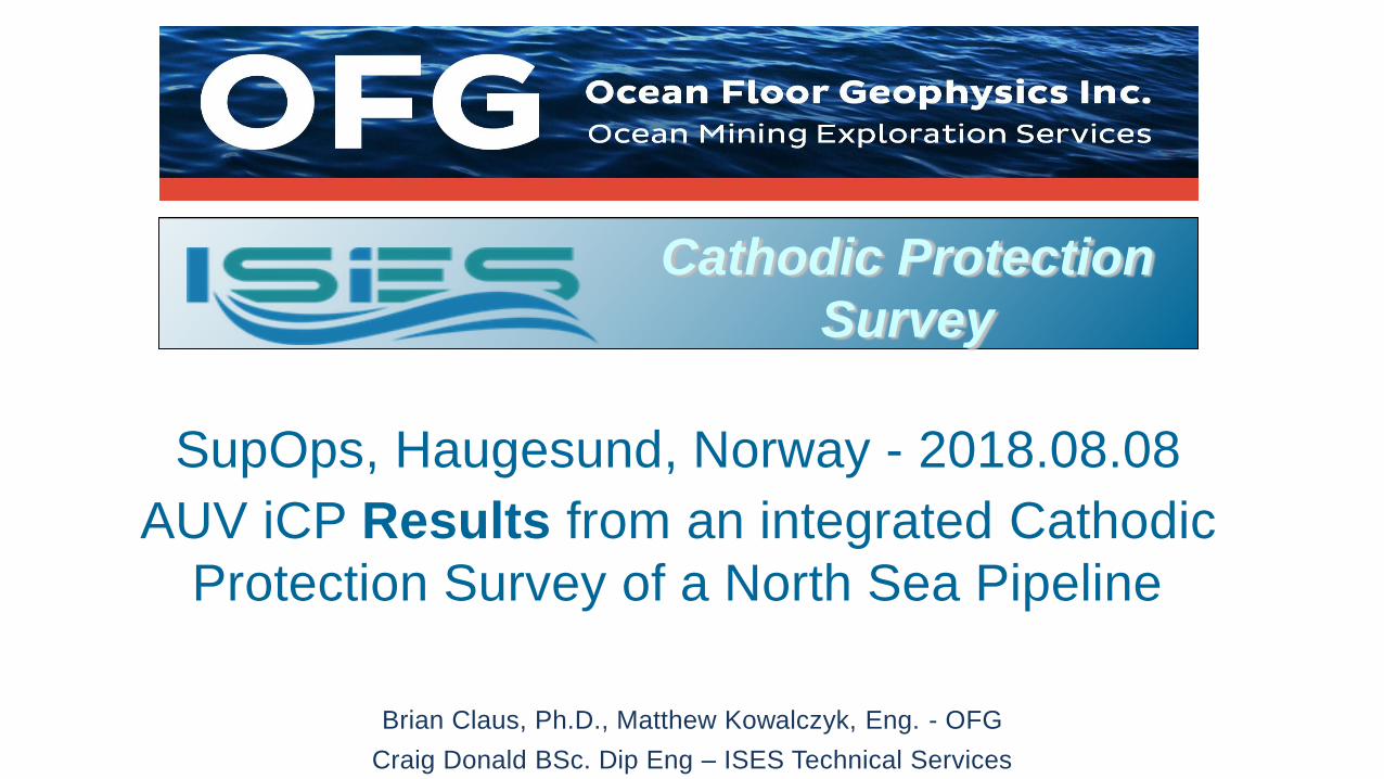
SupOps, Haugesund, Norway - 2018.08.08
AUV iCP Results from an integrated Cathodic
Protection Survey of a North Sea Pipeline
Brian Claus, Ph.D., Matthew Kowalczyk, Eng. - OFG
Craig Donald BSc. Dip Eng – ISES Technical Services
Cathodic Protection
Survey
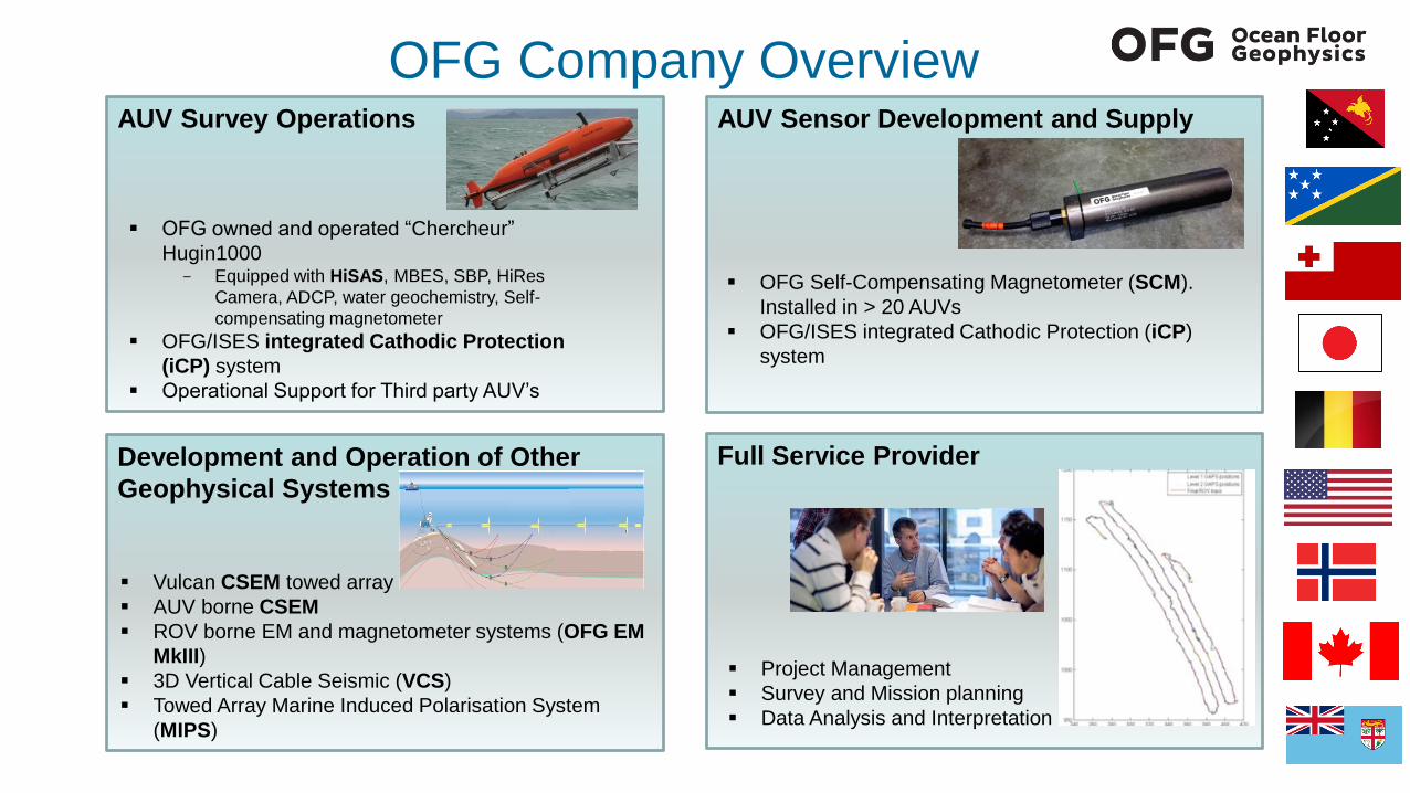
OFG Company OverviewAUV Sensor Development and SupplyAUV Survey Operations
OFG owned and operated “Chercheur”
Hugin1000 - Equipped with HiSAS, MBES, SBP, HiRes
Camera, ADCP, water geochemistry, Self-
compensating magnetometer
OFG/ISES integrated Cathodic Protection
(iCP) system
Operational Support for Third party AUV’s
OFG Self-Compensating Magnetometer (SCM).
Installed in > 20 AUVs
OFG/ISES integrated Cathodic Protection (iCP)
system
Full Service Provider
Project Management
Survey and Mission planning
Data Analysis and Interpretation
Development and Operation of Other
Geophysical Systems
Vulcan CSEM towed array
AUV borne CSEM
ROV borne EM and magnetometer systems (OFG EM
MkIII)
3D Vertical Cable Seismic (VCS)
Towed Array Marine Induced Polarisation System
(MIPS)
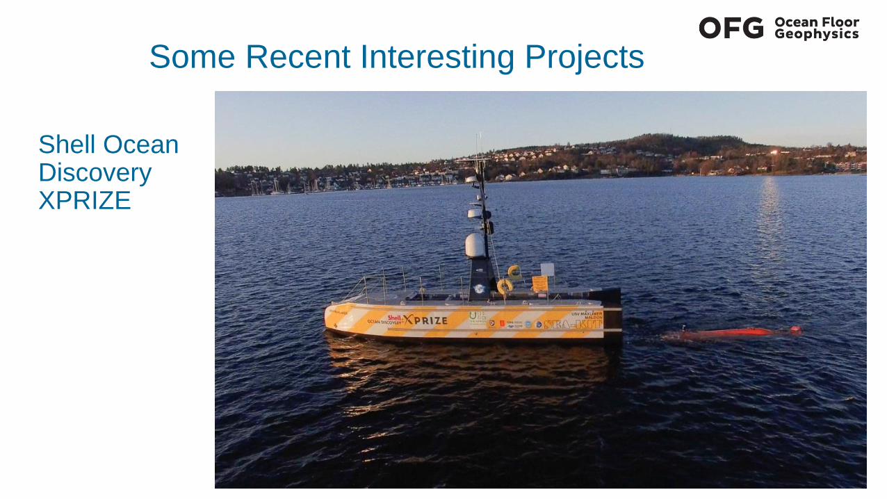
Some Recent Interesting Projects
Shell Ocean Discovery XPRIZE
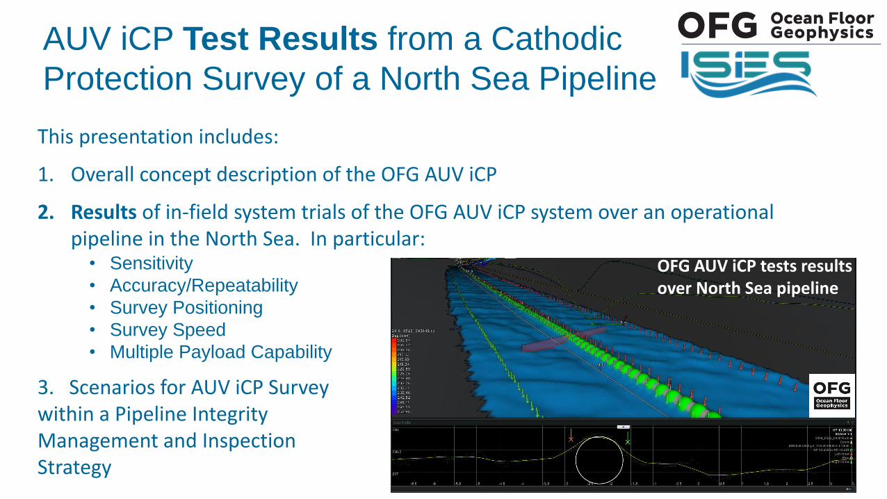
AUV iCP Test Results from a Cathodic
Protection Survey of a North Sea Pipeline
This presentation includes:
1. Overall concept description of the OFG AUV iCP
2. Results of in-field system trials of the OFG AUV iCP system over an operational pipeline in the North Sea. In particular:
• Sensitivity
• Accuracy/Repeatability
• Survey Positioning
• Survey Speed
• Multiple Payload Capability
3. Scenarios for AUV iCP Surveywithin a Pipeline Integrity Management and Inspection Strategy
OFG AUV iCP tests results over North Sea pipeline
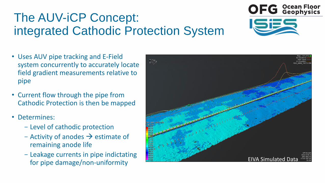
• Uses AUV pipe tracking and E-Field system concurrently to accurately locate field gradient measurements relative to pipe
• Current flow through the pipe from Cathodic Protection is then be mapped
• Determines:
- Level of cathodic protection
- Activity of anodes estimate of remaining anode life
- Leakage currents in pipe indictatingfor pipe damage/non-uniformity
The AUV-iCP Concept:integrated Cathodic Protection System
EIVA Simulated Data
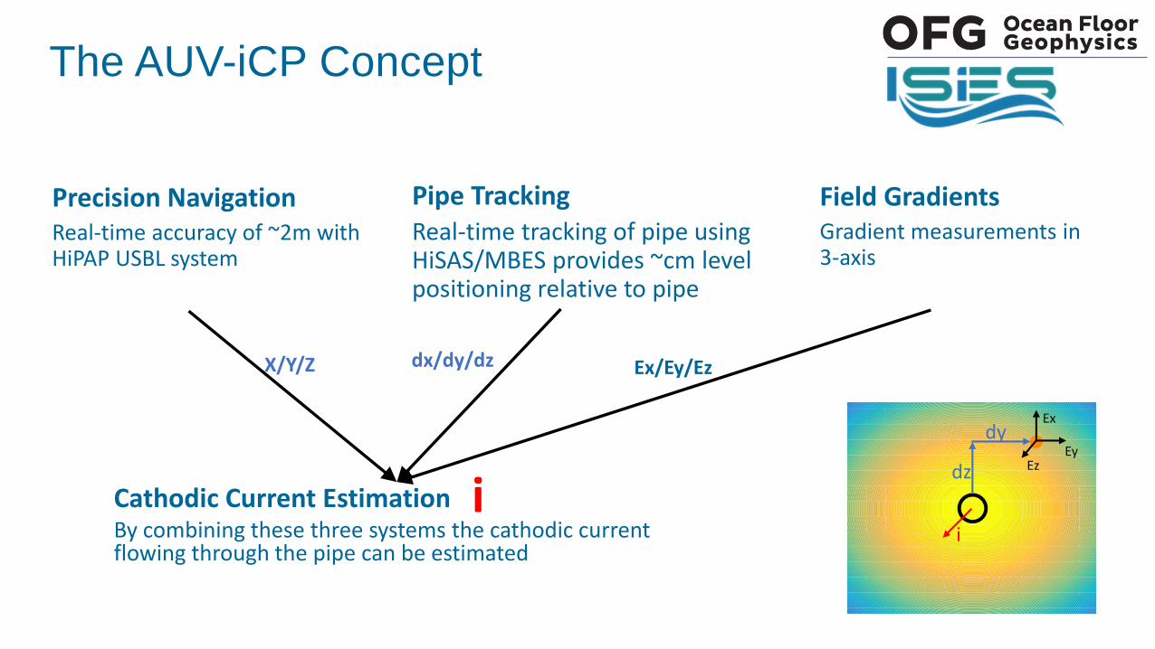
Precision NavigationReal-time accuracy of ~2m with HiPAP USBL system
Pipe TrackingReal-time tracking of pipe using HiSAS/MBES provides ~cm level positioning relative to pipe
Field GradientsGradient measurements in 3-axis
Cathodic Current EstimationBy combining these three systems the cathodic current flowing through the pipe can be estimated
dz
dyEx
EyEz
i
dx/dy/dz Ex/Ey/Ez
i
X/Y/Z
The AUV-iCP Concept
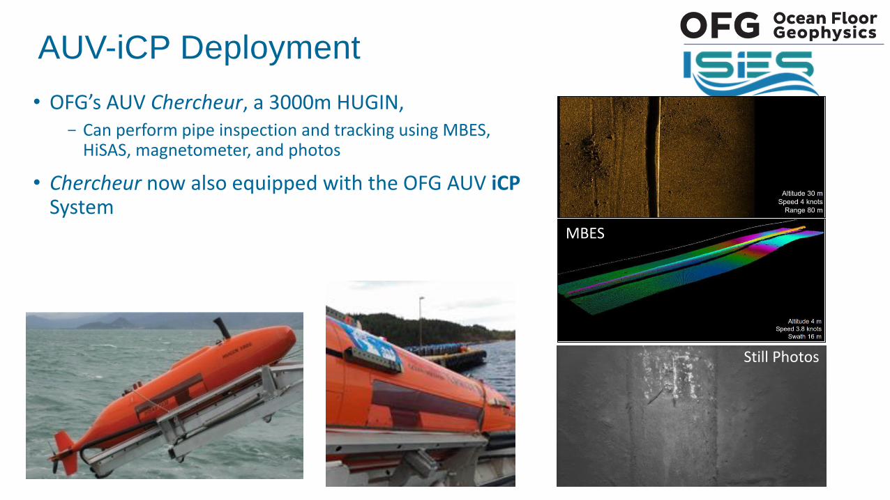
• OFG’s AUV Chercheur, a 3000m HUGIN, - Can perform pipe inspection and tracking using MBES,
HiSAS, magnetometer, and photos
• Chercheur now also equipped with the OFG AUV iCPSystem
MBES
AUV-iCP Deployment
Still Photos
AUV iCP Trials over a North Sea Pipeline
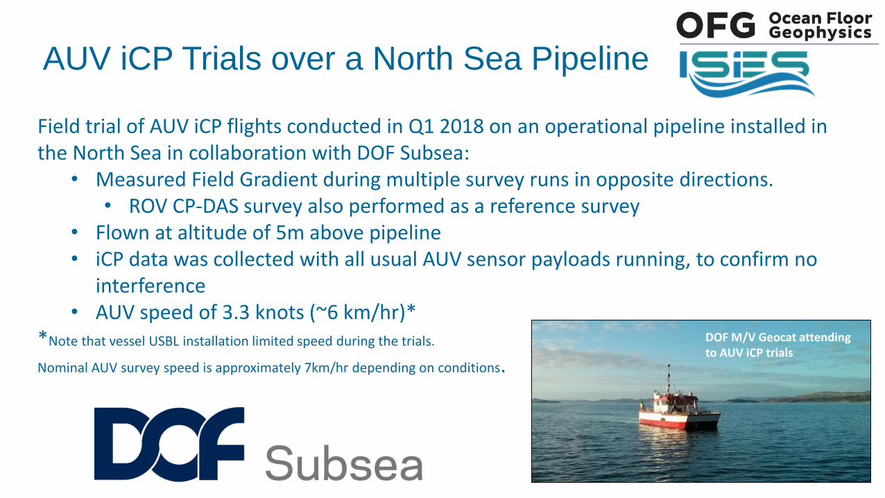
Field trial of AUV iCP flights conducted in Q1 2018 on an operational pipeline installed in the North Sea in collaboration with DOF Subsea:
• Measured Field Gradient during multiple survey runs in opposite directions. • ROV CP-DAS survey also performed as a reference survey
• Flown at altitude of 5m above pipeline• iCP data was collected with all usual AUV sensor payloads running, to confirm no
interference• AUV speed of 3.3 knots (~6 km/hr)*
*Note that vessel USBL installation limited speed during the trials.
Nominal AUV survey speed is approximately 7km/hr depending on conditions.
DOF M/V Geocat attending to AUV iCP trials
AUV iCP Sensitivity Test Results
• Variations of approximately 0.01µV/cm were reliably and repeatedly detected.
• The results confirmed during multiple test runs in both directions along pipeline
• The test results indicate that the system is approaching a detection limit TEN times that of any other available field gradient logging system (as per published results).
• UNAMBIGUOUS AND REPEATABLE

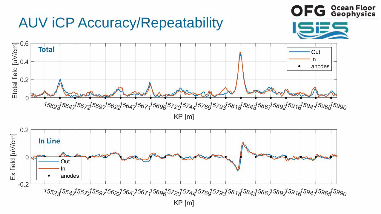
AUV iCP Accuracy/Repeatability
Measured FG data showing 2 survey runs in opposite directions
Cross
Vertical
In Line
Standard deviation of difference between measurements in opposite directions:
Et = 0.021µV/cmEx = 0.012µV/cmEy = 0.015µV/cmEz = 0.027µV/cm
- Without correction for position, range, attitude. - Difference is between entire length of pipe that was surveyed in both
directions at the same altitude.
Total
AUV iCP Accuracy/Repeatability
In Line
Total
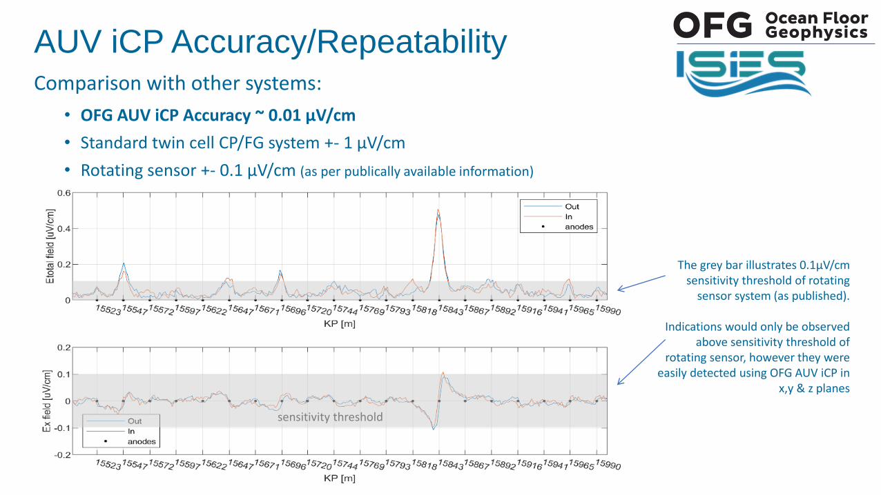
• OFG AUV iCP Accuracy ~ 0.01 µV/cm
• Standard twin cell CP/FG system +- 1 µV/cm
• Rotating sensor +- 0.1 µV/cm (as per publically available information)
AUV iCP Accuracy/RepeatabilityComparison with other systems:
The grey bar illustrates 0.1µV/cm sensitivity threshold of rotating
sensor system (as published).
Indications would only be observed above sensitivity threshold of
rotating sensor, however they were easily detected using OFG AUV iCP in
x,y & z planes
sensitivity threshold
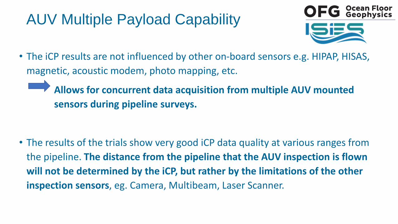
• The iCP results are not influenced by other on-board sensors e.g. HIPAP, HISAS,
magnetic, acoustic modem, photo mapping, etc.
Allows for concurrent data acquisition from multiple AUV mounted
sensors during pipeline surveys.
• The results of the trials show very good iCP data quality at various ranges from
the pipeline. The distance from the pipeline that the AUV inspection is flown
will not be determined by the iCP, but rather by the limitations of the other
inspection sensors, eg. Camera, Multibeam, Laser Scanner.
AUV Multiple Payload Capability
OFG AUV iCP tests results over North Sea pipelineThis image- MBES bathymetry - Pipeline model from MBES data- Camera imagery draped over pipeline
model
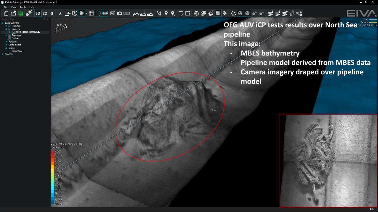
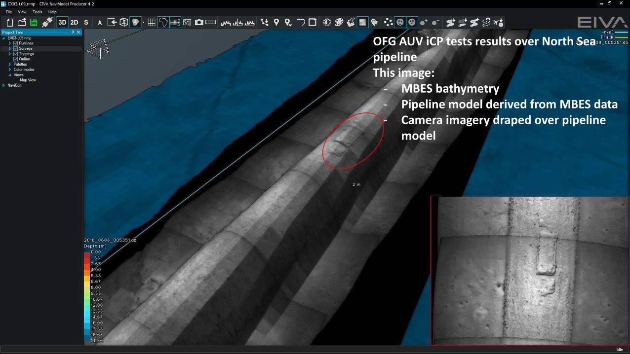
OFG AUV iCP tests results over North Sea pipelineThis image:
- MBES bathymetry - Pipeline model derived from MBES data- Camera imagery draped over pipeline
model
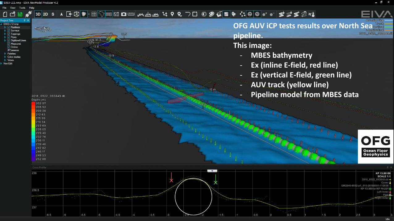
OFG AUV iCP tests results over North Sea pipeline.This image:
- MBES bathymetry - Ex (inline E-field, red line)- Ez (vertical E-field, green line)- AUV track (yellow line)- Pipeline model from MBES data
OFG AUV iCP tests results over North Sea pipelineThis image:
- MBES bathymetry - Pipeline model derived from MBES data- Camera imagery draped over pipeline
model
OFG AUV iCP tests results over North Sea pipelineThis image- MBES bathymetry - Pipeline model from MBES data- Camera imagery draped over pipeline
model
OFG AUV iCP tests results over North Sea pipelineThis image- MBES bathymetry - Pipeline model derived from MBES
data- Camera imagery draped over pipeline
model
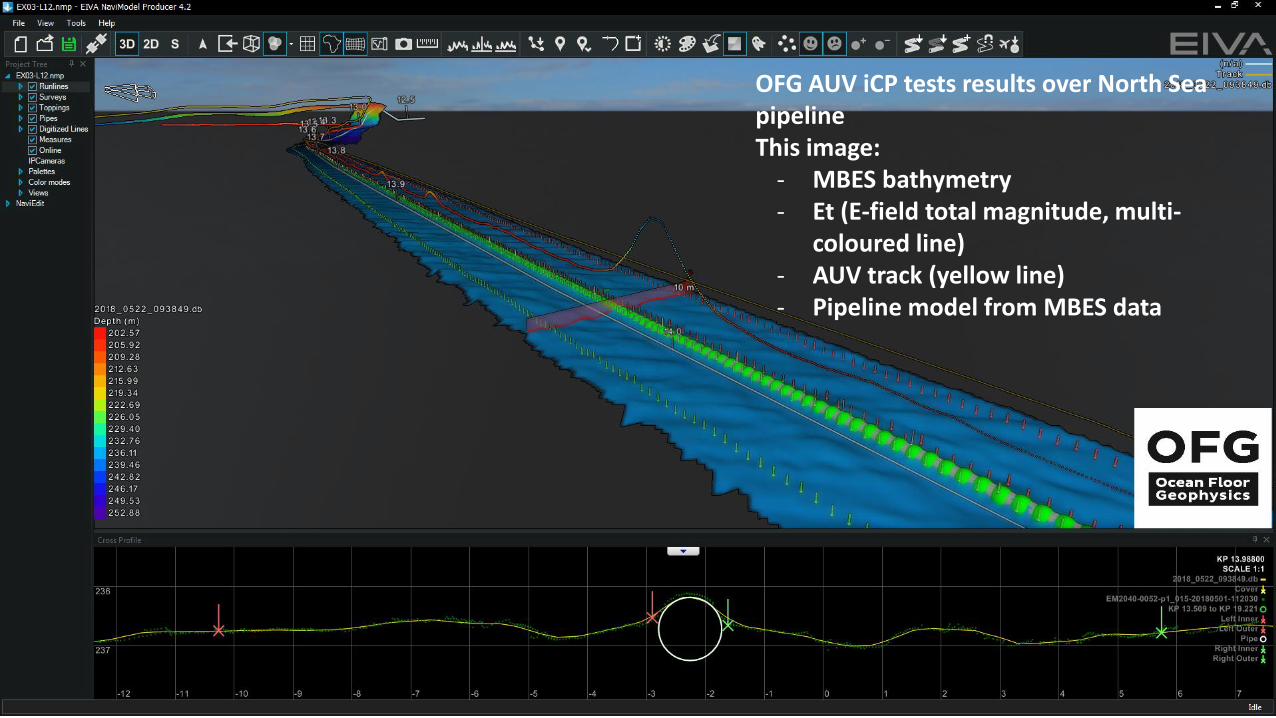
OFG AUV iCP tests results over North Sea pipelineThis image:
- MBES bathymetry - Et (E-field total magnitude, multi-
coloured line)- AUV track (yellow line)- Pipeline model from MBES data
Scenarios for AUV iCP Survey within a
Pipeline Integrity Management and
Inspection Strategy
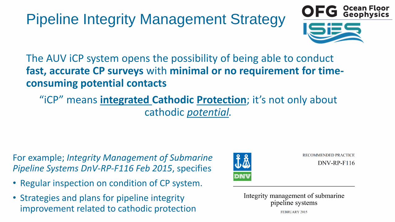
For example; Integrity Management of Submarine Pipeline Systems DnV-RP-F116 Feb 2015, specifies
• Regular inspection on condition of CP system.
• Strategies and plans for pipeline integrity improvement related to cathodic protection
Pipeline Integrity Management Strategy
The AUV iCP system opens the possibility of being able to conduct fast, accurate CP surveys with minimal or no requirement for time-consuming potential contacts
“iCP” means integrated Cathodic Protection; it’s not only about cathodic potential.
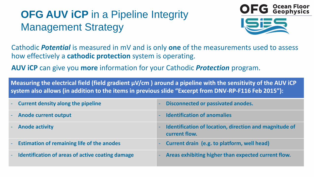
Cathodic Potential is measured in mV and is only one of the measurements used to assess how effectively a cathodic protection system is operating.
AUV iCP can give you more information for your Cathodic Protection program.
OFG AUV iCP in a Pipeline Integrity
Management Strategy
Measuring the electrical field (field gradient µV/cm ) around a pipeline with the sensitivity of the AUV iCP system also allows (in addition to the items in previous slide “Excerpt from DNV-RP-F116 Feb 2015”):
- Current density along the pipeline - Disconnected or passivated anodes.
- Anode current output - Identification of anomalies
- Anode activity - Identification of location, direction and magnitude of current flow.
- Estimation of remaining life of the anodes - Current drain (e.g. to platform, well head)
- Identification of areas of active coating damage - Areas exhibiting higher than expected current flow.
Pipeline Integrity Management Strategy
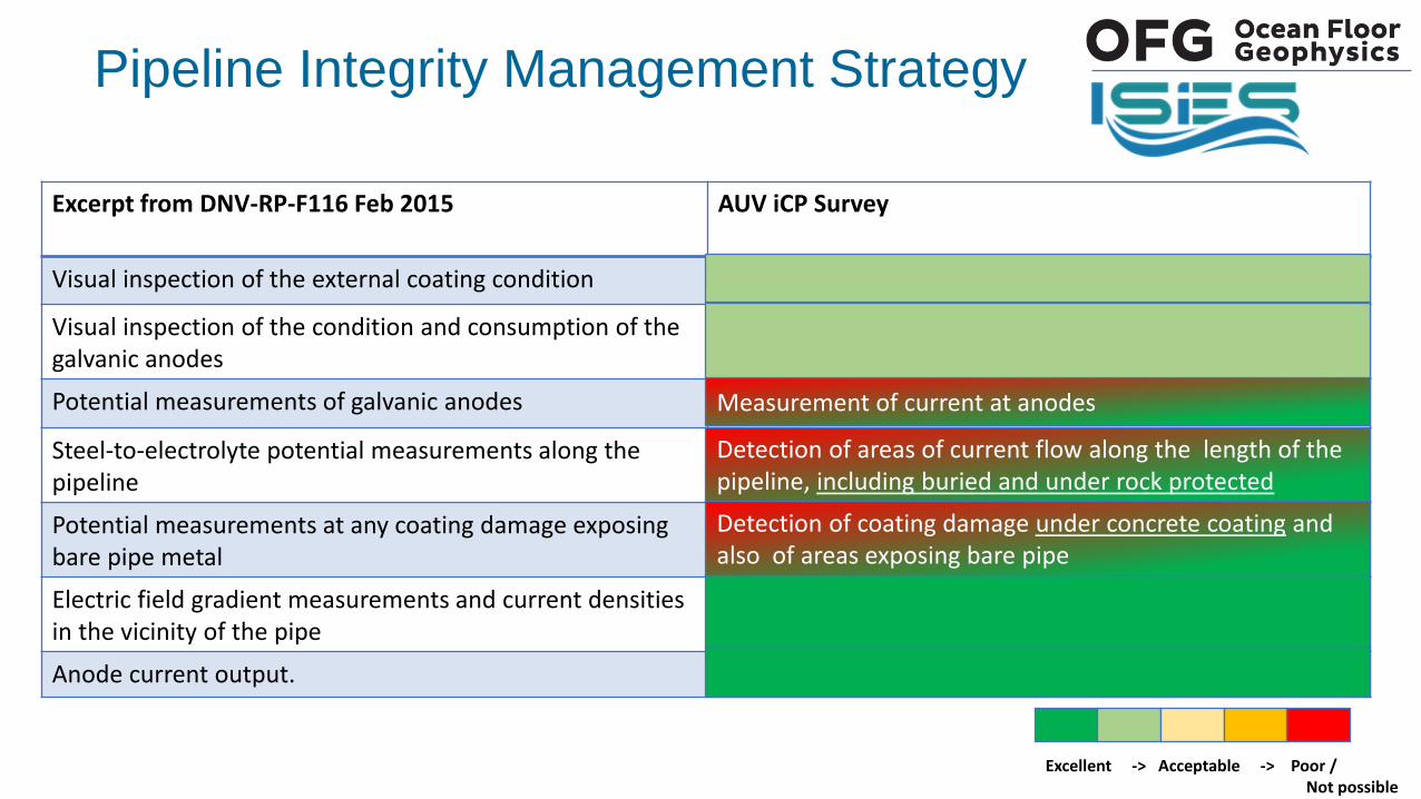
Excerpt from DNV-RP-F116 Feb 2015 AUV iCP Survey
Visual inspection of the external coating condition
Visual inspection of the condition and consumption of the galvanic anodes
Potential measurements of galvanic anodes
Steel-to-electrolyte potential measurements along the pipeline
Potential measurements at any coating damage exposing bare pipe metal
Electric field gradient measurements and current densities in the vicinity of the pipe
Anode current output.
Excellent -> Acceptable -> Poor / Not possible
Measurement of current at anodes
Detection of areas of current flow along the length of the pipeline, including buried and under rock protected
Detection of coating damage under concrete coating and also of areas exposing bare pipe
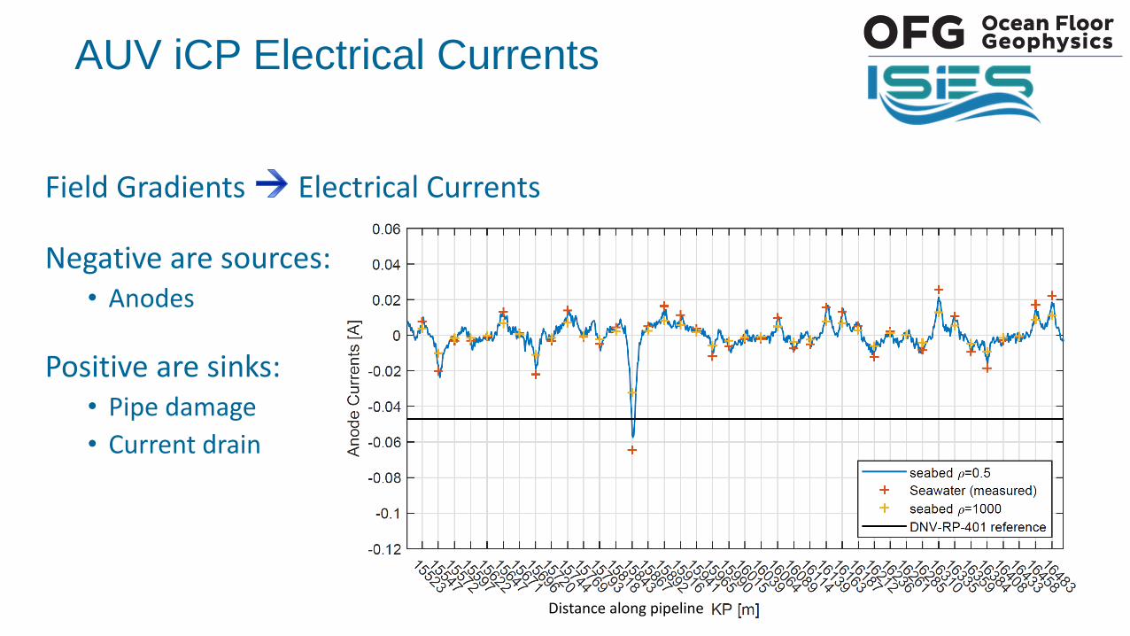
AUV iCP Electrical Currents
Field Gradients Electrical Currents
Negative are sources:• Anodes
Positive are sinks:• Pipe damage
• Current drain
Distance along pipeline
A D
-1040
-900
-850
-650
mV wrt Ag/AgCl
B C
Protected Design Life – Stable Conditions (e.g. 20 years)
Polar-isation
Depolar-
isationUnder Protected
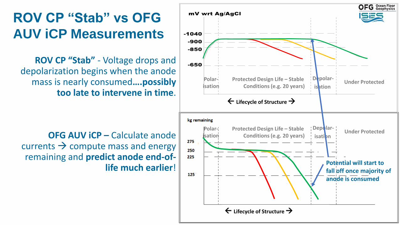
ROV CP “Stab” vs OFG
AUV iCP Measurements
Lifecycle of Structure
ROV CP “Stab” - Voltage drops and depolarization begins when the anode
mass is nearly consumed….possibly too late to intervene in time.
OFG AUV iCP – Calculate anode currents compute mass and energy remaining and predict anode end-of-
life much earlier!
Protected Design Life – Stable Conditions (e.g. 20 years)
Polar-isation
Depolar-
isationUnder Protected
Potential will start to fall off once majority of anode is consumed
Lifecycle of Structure
Scenario One - Post lay baseline/tie-in CP survey
Scenario Two - Maintenance CP survey
Scenario Three - Intervention CP survey
OFG AUV iCP Usage Scenarios
in a Pipeline Integrity Management Strategy
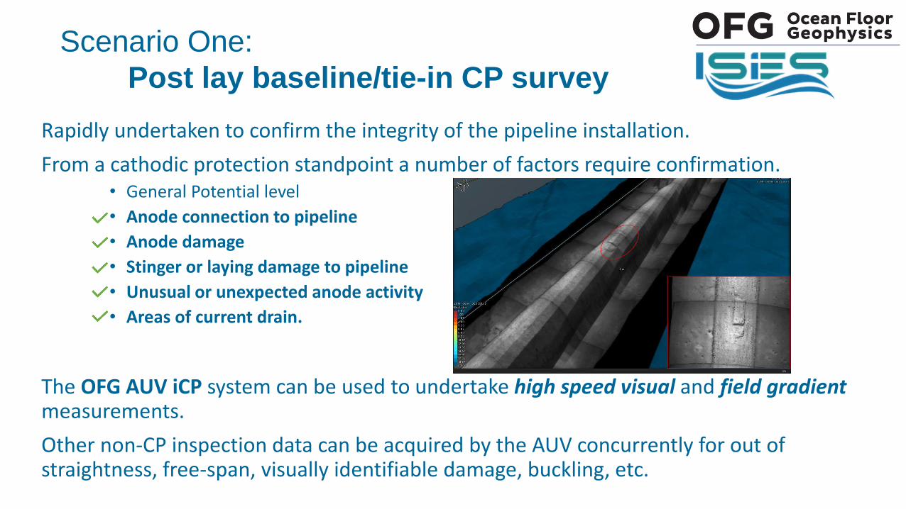
Rapidly undertaken to confirm the integrity of the pipeline installation.
From a cathodic protection standpoint a number of factors require confirmation. • General Potential level
• Anode connection to pipeline
• Anode damage
• Stinger or laying damage to pipeline
• Unusual or unexpected anode activity
• Areas of current drain.
The OFG AUV iCP system can be used to undertake high speed visual and field gradient measurements.
Other non-CP inspection data can be acquired by the AUV concurrently for out of straightness, free-span, visually identifiable damage, buckling, etc.
Scenario One:
Post lay baseline/tie-in CP survey
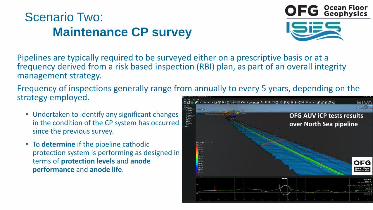
Pipelines are typically required to be surveyed either on a prescriptive basis or at a frequency derived from a risk based inspection (RBI) plan, as part of an overall integrity management strategy.
Frequency of inspections generally range from annually to every 5 years, depending on the strategy employed.
Scenario Two:
Maintenance CP survey
• Undertaken to identify any significant changes in the condition of the CP system has occurred since the previous survey.
• To determine if the pipeline cathodic protection system is performing as designed in terms of protection levels and anode performance and anode life.
OFG AUV iCP tests results over North Sea pipeline
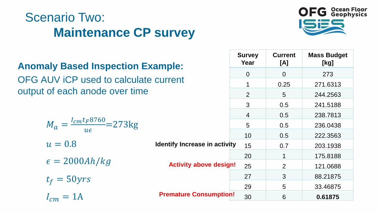
Anomaly Based Inspection Example:
OFG AUV iCP used to calculate current
output of each anode over time
𝑀𝑎 =𝐼𝑐𝑚𝑡𝐹8760
𝑢𝜖=273kg
𝑢 = 0.8
𝜖 = 2000𝐴ℎ/𝑘𝑔
𝑡𝑓 = 50𝑦𝑟𝑠
𝐼𝑐𝑚 = 1A
Scenario Two:
Maintenance CP survey
Survey
Year
Current
[A]
Mass Budget
[kg]
0 0 273
1 0.25 271.6313
2 5 244.2563
3 0.5 241.5188
4 0.5 238.7813
5 0.5 236.0438
10 0.5 222.3563
15 0.7 203.1938
20 1 175.8188
25 2 121.0688
27 3 88.21875
29 5 33.46875
30 6 0.61875Premature Consumption!
Identify Increase in activity
Activity above design!
Undertaken if something significant has been identified which could affect the cathodic protection system, for example:
• Pipeline damage• Post anode retrofit survey• Additional connections to pipeline e.g. tie-ins new well, risers, manifolds and structures.
The iCP system can be used to undertake a rapid assessment of the condition of the pipeline after the event has occurred to provide accurate information on the activity of the anodes and identify if there is a correlation between areas of damage and current drain and measure the effects.
Scenario Three:
Intervention CP surveys
The passive, non-contact AUV iCP system allows fast, accurate CP surveys to be conducted:
1. Real-time pipe tracking and inspection using MBES, HISAS, magnetometer and photos
2. Accurately detect and quantify Field Gradient (FG) along a pipeline route at significantly higher speeds than an ROV survey.
3. Detect & quantify pipeline electrical fields to an unprecedented level (variations of ~0.01µV/cm) from which currents (anodes and also damaged areas) can be calculated
4. Signal accuracy was not reduced by either vertical or horizontal standoff distances between the AUV and the pipeline.
5. Gather multiple data sets from other sensors simultaneously without degrading the received FG signals due to system’s operations noise.
6. The system can add significant value in efficiency and cost savings when used as part of an integrated pipeline inspection management strategy.
• Instead of a contact every km this could may be reduced to a handful of selected key point contacts along the entire pipeline route
OFG AUV iCP
Conclusions Based on Field Trials
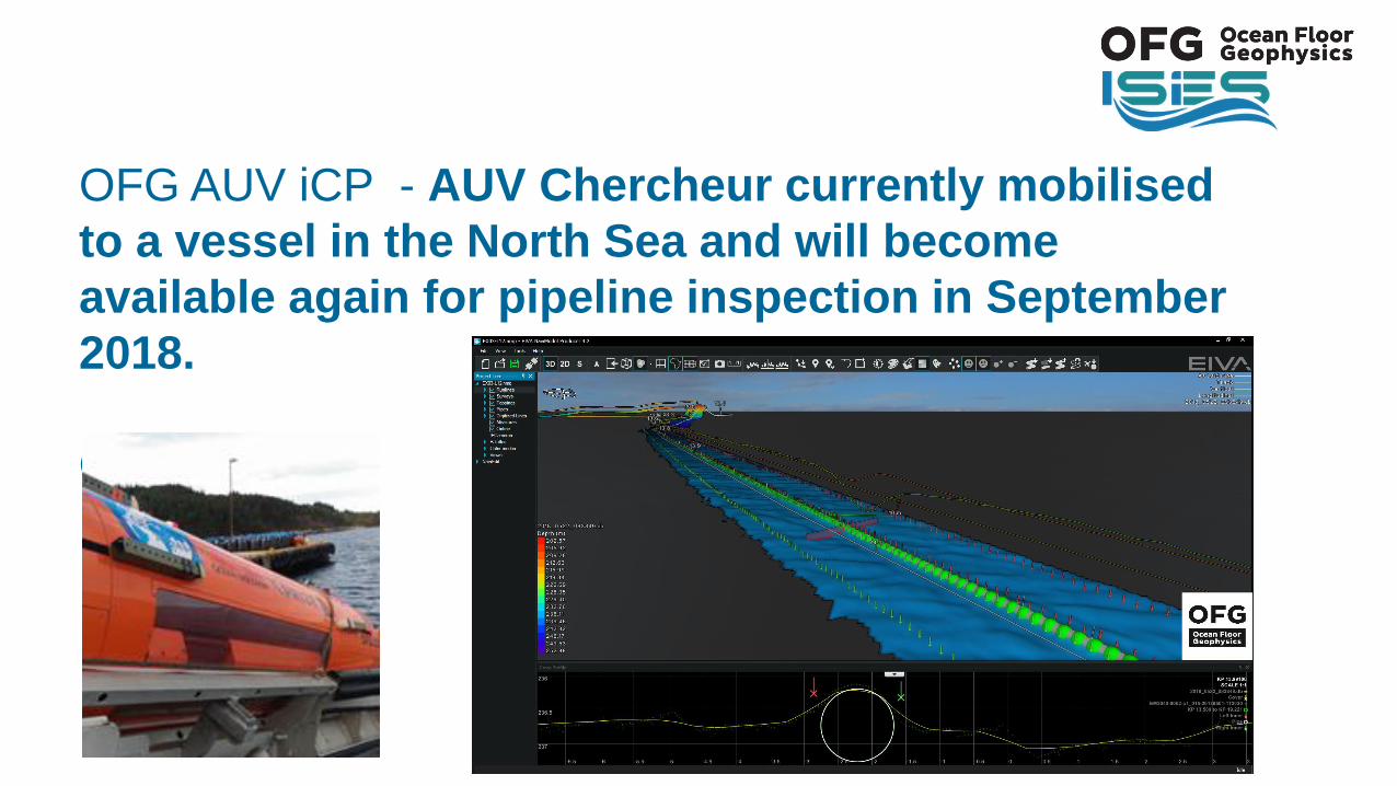
OFG AUV iCP - AUV Chercheur currently mobilised
to a vessel in the North Sea and will become
available again for pipeline inspection in September
2018.
Questions?

Technical Services Ltd
Europe
ISES Technical Services Limited
1st Floor, Block 7, The Altec Centre
Minto Drive, Altens Industrial Estate
Aberdeen AB12 3LW, Scotland
Tel: 01224 874440
Fax: 01224 872211
Asia Pacific
ISES Technical Services PTE Ltd.
No 38 Loyang Drive, Unit 01-03
Loyang Industrial Estate
Singapore 508960
Tel +65 65 467228
Malaysia
Inspection Survey & Integrity Services Sdn Bhd
CT-10-07 Subang Square Corporate Tower
Jln SS15/4G, 47500 Suband Jaya, Selangor, Malaysia
Tel: +6 03 5635 9500 / 9850 / 9750
Fax: +6 03 5635 9655
Web Site: www.ises.techEmail: [email protected]

34
Ocean Floor Geophysics Inc.
B108 – 9000 Bill Fox Way
Burnaby, BC
Canada V5J 5J3
T: +1-778-654-7781