CATHODIC PROTECTION AN OVERVIEW · CATHODIC PROTECTION AN OVERVIEW WHAT IS IT? Cathodic protection...
22
CATHODIC PROTECTION AN OVERVIEW WHAT IS IT? Cathodic protection (CP) is a method of corrosion control that can be applied to buried and submerged metallic structures. It is normally used in conjunction with coatings and can be considered as a secondary corrosion control technique. The primary corrosion control method on any given structure is normally a coating system which is can be between 50 and 99 % efficient depending upon age, type, method of installation, etc. A properly designed and maintained cathodic protection system will take up the remainder resulting in a 100 % efficient corrosion protection system. WHY IS IT IMPORTANT? Corrosion costs money. It is estimated that somewhere between 3 and 5 % of the gross national product (GNP) of industrialised countries is attributed to corrosion damage 1 . Corrosion of metals costs the USA economy almost $300 billion per year and it is estimated that one third of this value could be saved with better selection of corrosion prevention techniques, including cathodic protection. WHY DOES CORROSION OCCUR? The corrosion of metals, in particular steel, in an aqueous environment (which can be either soil or water), occurs because the metal interacts with the local environment. In the case of steel, man has mined iron ore and processed it into steel. However due to certain characteristics of the steel, it is not ‘stable’ once in contact with an aqueous environment and interacts with the local environment in an attempt to return to its naturally occurring state. This process is corrosion. The basic process at an anodic site is the release of iron (Fe) from the steel surface into the environment and can be expressed as: Fe → Fe 2+ + 2e ‐ 1 Handbook of Corrosion Engineering; Pierre R. Roberge; 1 st Edition
Transcript of CATHODIC PROTECTION AN OVERVIEW · CATHODIC PROTECTION AN OVERVIEW WHAT IS IT? Cathodic protection...

CATHODIC PROTECTION AN OVERVIEW
WHAT IS IT?
Cathodic protection (CP) is a method of corrosion control that can be applied to buried and submerged
metallic structures.
It is normally used in conjunction with coatings and can be considered as a secondary corrosion control
technique. The primary corrosion control method on any given structure is normally a coating system
which is can be between 50 and 99 % efficient depending upon age, type, method of installation, etc.
A properly designed and maintained cathodic protection system will take up the remainder resulting
in a 100 % efficient corrosion protection system.
WHY IS IT IMPORTANT?
Corrosion costs money.
It is estimated that somewhere between 3 and 5 % of the gross national product (GNP) of
industrialised countries is attributed to corrosion damage1. Corrosion of metals costs the USA
economy almost $300 billion per year and it is estimated that one third of this value could be saved
with better selection of corrosion prevention techniques, including cathodic protection.
WHY DOES CORROSION OCCUR?
The corrosion of metals, in particular steel, in an aqueous environment (which can be either soil or
water), occurs because the metal interacts with the local environment. In the case of steel, man has
mined iron ore and processed it into steel. However due to certain characteristics of the steel, it is not
‘stable’ once in contact with an aqueous environment and interacts with the local environment in an
attempt to return to its naturally occurring state. This process is corrosion.
The basic process at an anodic site is the release of iron (Fe) from the steel surface into the
environment and can be expressed as:
Fe → Fe2+ + 2e‐
1 Handbook of Corrosion Engineering; Pierre R. Roberge; 1st Edition

During the process two electrons (2e‐) are generated which must be consumed by the environment
(in aerated systems) and can be expressed as:
4H+ + O2 + 4e‐ → 2H2O
A summary of the above half reactions can be expressed as:
2Fe + 2H2O + O2 → 2Fe(OH)2
The term Fe(OH)2 is iron oxide which can be oxidised to form the red‐brown Fe(OH)3 commonly
referred to as rust.
HISTORY
The first application of CP dates back to 1824, long before its theoretical foundation was established,
and is credited to Sir Humphrey Davy. Davy cathodically protected copper sheeting used for cladding
the hulls of naval vessels in seawater with iron, zinc or tin.
In the USA by 1945 the use of CP was commonly applied to the rapidly expanding oil and natural gas
industry. In the UK CP was applied from the 1950s onwards and Cathodic Protection Company Limited
was established in this period, pioneering it’s use in the UK.
CP is now well established on a large variety of immersed and buried metallic structures as well as
reinforced concrete structures, and provides effective corrosion control.
HOW DOES IT WORK?
Simply CP works by preventing the anodic reaction of metal dissolution occurring on the structure
under protection.
As shown in the equations in the section above, generally, corrosion can be classified as an
electrochemical process and subsequent control of these equations can prevent corrosion from
occurring.
Corrosion occurs at the anode as this is where electrons are released. In order to complete the
electrical circuit the electrons must flow to the cathode, as per the illustrations below:

The principle of cathodic protection is to prevent anodic sites occurring on the structure under
protection by allowing the anodic reactions to occur on specially designed and installed anodes. For
simplification the illustration “Corrosion Cell Stage 3” above demonstrates this with all the “rust”
formed on the anode and none on the cathode.
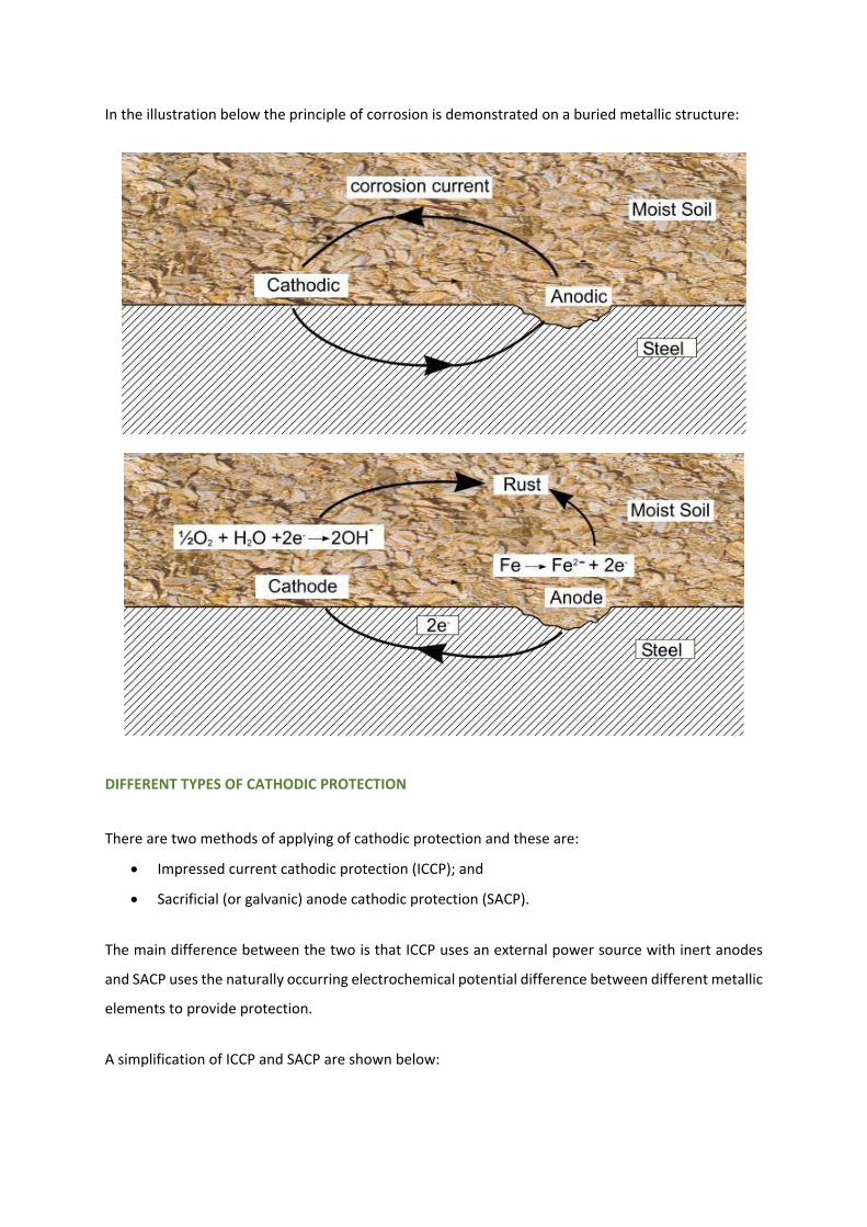
In the illustration below the principle of corrosion is demonstrated on a buried metallic structure:
DIFFERENT TYPES OF CATHODIC PROTECTION
There are two methods of applying of cathodic protection and these are:
Impressed current cathodic protection (ICCP); and
Sacrificial (or galvanic) anode cathodic protection (SACP).
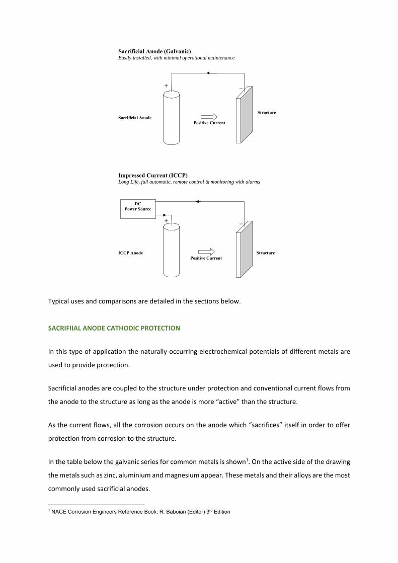
The main difference between the two is that ICCP uses an external power source with inert anodes
and SACP uses the naturally occurring electrochemical potential difference between different metallic
elements to provide protection.
A simplification of ICCP and SACP are shown below:
Typical uses and comparisons are detailed in the sections below.
SACRIFIIAL ANODE CATHODIC PROTECTION
In this type of application the naturally occurring electrochemical potentials of different metals are
used to provide protection.
Sacrificial anodes are coupled to the structure under protection and conventional current flows from
the anode to the structure as long as the anode is more “active” than the structure.
As the current flows, all the corrosion occurs on the anode which “sacrifices” itself in order to offer
protection from corrosion to the structure.
In the table below the galvanic series for common metals is shown1. On the active side of the drawing
the metals such as zinc, aluminium and magnesium appear. These metals and their alloys are the most
commonly used sacrificial anodes.
1 NACE Corrosion Engineers Reference Book; R. Baboian (Editor) 3rd Edition
Sacrificial Anode (Galvanic)Easily installed, with minimal operational maintenance
+ _
StructureSacrificial Anode
Positive Current
Impressed Current (ICCP)Long Life, full automatic, remote control & monitoring with alarms
+ _
ICCP Anode Structure Positive Current
DCPower Source

The uses and benefits of SACP systems are detailed in the comparison table below.
IMPRESSED CURRENT CATHODIC PROTECTION
With an impressed current system the current is “impressed” or forced by a power supply. The power
source must be able to deliver direct current (DC) and examples are transformer rectifier units, solar
generating units or thermo‐electric generators.
The anodes are either inert or have low consumption rates and can be surrounded by carbonaceous
backfill to increase efficiency and decrease costs. Typical anodes are titanium coated with mixed metal
oxide (MMO) or platinum, silicon iron, graphite and magnetite.
The uses and benefits of ICCP systems are detailed in the comparison table below.
NEW BUILD OR RETROFIT
Cathodic protection can be applied to both new build and existing structures. It is recommended that
cathodic protection is considered for all metallic structures, especially carbon and other low alloy
steels, in contact with soil or water.

CORROSIVENESS OF SOILS AND WATERS
The corrosivity of soils and waters is dependent upon several characteristics, which determine the
rate of oxygen related corrosion. These include resistivity, salt content (chloride), sulphate content,
pH and oxygen availability.
Significant numbers of corrosion events can be attributed to bacterial and micro‐bacterial corrosion
and common terminology includes sulphate reducing bacteria (SRB) and accelerated low water
corrosion (ALWC).
The most important of all the factors is the resistivity of the environment and it can be easily measured
by CP personnel. However it is not possible to determine resistivity from the type of soil, location or
water content and must be measured at each and every location.
The corrosiveness of an environment can be classified due to its resistivity and from BS 7361: Part 1:
Resistivity Corrosivity Ranking
Up to 10 Ohm.m Severely Corrosive
10 to 50 Ohm.m Corrosive
50 to 100 Ohm.m Moderately Corrosive
100 Ohm.m and above Slightly Corrosive
The resistivity of seawater is generally in the region of 0.25 to 0.3 Ohm.m but varies greatly in brackish
and estuarine locations.

COMPARISON TABLE OF THE TYPES OF CP
A comparison of the two types of CP is shown below and adapted from BS 7361: Part 1: 1991:
SACRIFICIAL ANODES (GALVANIC)
IMPRESSED CURRENT (ICCP)
USES o Generally used for protection of well coated
areas where protective current requirements and soil or water resistivities are low.
o Where the surface area of a protected
structure is relatively small due to economic restrictions.
BENEFITS AND FEATURES No independent source of electric power
required. Limited affects on neighbouring structures. Extremely simple to install. May be directly
fixed to the structure.
Simple additions can be made until the desired effect is achieved
Anode connections are also protected.
Self adjusting but the output generally
cannot be controlled Correct material selection ensures no over
protection, thus avoiding metal embrittlement and coating damage.
No possibility of plant damage due to
incorrect connections ie. reversed polarity.
Straight forward to install, operate and maintain
USES o For structures where protective current
requirements and life requirements are high. o Can be used over a wider range of soil and
water resistivities. o For protection of large uncoated areas, where
relatively few anodes are required. BENEFITS AND FEATURES Requires external power source
Can be applied to a wide range of structures
in various states of coating condition. May be adjusted manually or automatically to
cater for changing conditions. May be remotely adjusted, monitored and
connected to Plant Alarm System. Anodes are very compact, thus drag and
water flow restriction are negligible. Requires a small number of anodes
compared to a galvanic system.
Needs careful design and operation to ensure ongoing protection
Can affect other structures if not properly
monitored
Installation needs to ensure all connections have a high integrity of insulation and that damage does not occur due to reversed polarity.
WHAT STRUCTURES CAN IT PROTECT?
Cathodic protection can protect all types of buried and submerged metallic structures including:
Cross country pipelines

In plant piping
Aboveground storage tank bases
Buried tanks and vessels
Internal surfaces of tanks, vessels, condensers and pipes
Well casings
Piling – tubular, sheet steel and foundation
Marine structures including jetties, wharfs, harbours, piers, platforms
Ships
Reinforcing steel in concrete
The cathodic protection system can be designed to prevent both oxygen controlled and micro‐
biologically controlled corrosion.
Each CP system tends to be of bespoke design and the main materials are manufactured to order as
every location has it’s own variation in environment and current demand.
In addition to providing protective current each CP system design must consider:
Electrical continuity – structures must be electrical continuous to allow the protective current
to return to the power source.
Electrical isolation – structures must be electrically isolated from other buried metallic
structures to prevent current loss and under protection of the structure under consideration.
Testing facilities – must be installed to monitor the effectiveness of the CP system. Adjacent
CP and buried metallic structures should also be monitored to ensure no detrimental effects.
MARINE STRUCTURES
Marine structures are commonly cathodically protected by either impressed current or sacrificial
anodes. Cathodic protection is effective for the embedded and submerged sections of the pile. It
becomes less effective in increasing height of the splash zone where coatings need to be considered.
A typical unprotected pile and zones is demonstrated below:

SACP systems are normally of either aluminium or zinc anodes and less commonly magnesium. The
anode size is determined by current required and lifetime. Typical lifetime is around 10 to 20 years.
The anodes can be directly welded to the structure (stand‐off or flush mounted), mounted on a sled
or on the seabed and allowed to silt up. If the anodes are not directly connected then continuity to
the structure must be completed by a cable.
ICCP systems consist of a power source, normally transformer rectifiers, located on deck level and
submerged anodes. The anodes can be mounted on the structure, placed on a sled on the seabed or
buried in the seabed. Anode types can be mixed metal oxide (MMO) coated titanium – wire or tubular
type, platinised titanium or silicon iron (if buried). Typical lifetime is 20 plus years.
The anodes are connected to the transformer rectifier and in turn to the structure via series of suitably
rated (for immersion etc) and sized cables and junction boxes which must be suitable for the marine
environment. Junction boxes can be plastic, aluminium, steel or stainless steel and be certified for
hazardous areas as required. Common jackets and sheaths for cathodic protection cables are
XLPE/PVC, HMWPE, PVDF, EPR/CSP and armoured where necessary.
Cable to structure connections can be by pin brazing, thermit welding or welded connection plates
and connections require recoating after completion.
Monitoring of a marine CP system can be completed by permanently installed or portable reference
electrodes and test facilities. Permanent reference electrodes are normally either silver / silver
chloride or zinc type while portable can be similar or copper / copper sulphate. A multimeter
measuring milli‐volts and connection to the structure via cables and test post is required to complete

basic measurements. Structure‐to‐electrolyte potentials can also be monitored through CP coupons
located near to the permanently installed reference electrodes to reduce any effects of the “IR drop”.
INDUSTRIAL APPLICATIONS
Cathodic Protection can be used to protect the following structures either individually or more than
one type of structure with a single CP system.
PIPELINES
The application of cathodic protection to cross‐country pipelines and in‐plant piping can be completed
by the following means:
SACP
o Pre‐packaged anodes
o Ribbon anodes
ICCP
o Horizontal and vertical shallow groundbeds
o Canistered anodes
o Deepwell groundbeds
o Ribbon or wire anodes
A typical set‐up for SACP with pre‐packaged magnesium anodes is shown in the schematic drawing
below. Magnesium anodes are the most commonly used for soil applications due to their greater
electrochemical potential difference to steel, however in some applications zinc anodes are used.
Magnesium anode are supplied in two grades – “standard” or “high potential”. The high potential
grade has a more active potential of about 200 mV than the standard grade and can produce more
protective current in higher soil resistivities.
Magnesium anodes are normally installed within a few metres of pipe and at pipe invert depth. Due
to the limited driving potentials it is necessary to install anodes every few hundred metres which is
more suited to shorter pipe lengths. The numbers, sizes and weights of the anodes are determined by
calculation largely depending upon soil resistivity and the quality of the coating. Alternatively
magnesium or zinc ribbon anodes can be installed within the pipe trench, for the entire pipe length,
to provide local protection.
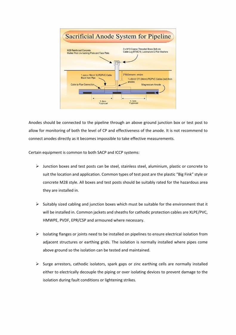
Anodes should be connected to the pipeline through an above ground junction box or test post to
allow for monitoring of both the level of CP and effectiveness of the anode. It is not recommend to
connect anodes directly as it becomes impossible to take effective measurements.
Certain equipment is common to both SACP and ICCP systems:
Junction boxes and test posts can be steel, stainless steel, aluminium, plastic or concrete to
suit the location and application. Common types of test post are the plastic “Big Fink” style or
concrete M28 style. All boxes and test posts should be suitably rated for the hazardous area
they are installed in.
Suitably sized cabling and junction boxes which must be suitable for the environment that it
will be installed in. Common jackets and sheaths for cathodic protection cables are XLPE/PVC,
HMWPE, PVDF, EPR/CSP and armoured where necessary.
Isolating flanges or joints need to be installed on pipelines to ensure electrical isolation from
adjacent structures or earthing grids. The isolation is normally installed where pipes come
above ground so the isolation can be tested and maintained.
Surge arrestors, cathodic isolators, spark gaps or zinc earthing cells are normally installed
either to electrically decouple the piping or over isolating devices to prevent damage to the
isolation during fault conditions or lightening strikes.

Cable to structure connections can be by pin brazing, thermit welding or welded connection
plates and connections should always be recoated after completion. Recoating of pipes should
be completed by a coating equivalent or better and compatible with the original.
Where pipelines enter cased crossings or other structures such as walls, chambers, pits etc
then casing insulators, link seals and end seals need to be considered to ensure isolation is
maintained and the pipe is adequately protected in these areas.
Monitoring of a CP systems can be completed by permanently installed or portable reference
electrodes and test facilities. Reference electrodes are normally copper / copper sulphate. A
multimeter measuring milli‐volts and connection to the structure via cables and test post is
required to complete basic measurements. Structure‐to‐electrolyte potentials can also be
monitored through CP coupons locate near the permanently installed reference electrodes to
reduce any effects of the “IR drop”.
Monitoring can also be completed using “pipeline compliance software”, field computers and
current interrupters or by installing remote monitoring equipment.
The ICCP system in the vast majority of cases is powered by a transformer rectifier unit which receives
AC power from the grid and produces controllable DC current used to provide the cathodic protection.
However in remote areas or where AC power is not available DC current can be generated from solar
panel units, thermo‐electric generators or DC‐DC convertors.
Groundbeds can either be close or remote. A close groundbed, as the name suggests is close to the
structure under protection and provides local protection. A remote groundbed is electrically speaking
located at “remote earth” which in general is 50 to 100 m from the structure. If the groundbed is at
remote earth the groundbed can protect the pipeline up to tens of kilometres away – which means
this is especially effective for protecting cross‐country pipelines. The actual length of the pipeline
protected is calculated by CP engineers and depends upon pipe thickness, driving voltage, coating and
soil resistivity.
Shown below is a typical schematic set‐up for an ICCP shallow vertical groundbed arrangement:

Mainly due to economical factors cross‐country pipelines are protected by horizontal or deepwell
remote groundbeds. In plant piping can be protected in the same manner. Alternatively for the shorter
lengths of pipes and other factors such as earthing grids, mass concrete shielding; then canistered
anodes or continuous ribbon anodes in a “close anode” arrangement can be both economically and
technically preferable.
Typical groundbeds used for ICCP pipeline systems are:
Horizontal and vertical shallow groundbeds
Horizontal and vertical shallow groundbeds are typically used for pipelines where space is not
an issue as the groundbed will need to be up to 100 m away from the pipeline and where soil
resistivity is reasonably low at the surface. These types of groundbed are more cost effective
to install than deepwell groundbeds.
Horizontal or vertical shallow groundbeds can consist of either rod or tubular silicon iron,
tubular MMO coated titanium anodes and less commonly graphite or magnetite anodes. Each
of the anodes has a cable tail which is connected by splice kit to a main header cable and in
turn is routed back the power supply. Alternatively a single anode string, especially common
with MMO coated titanium tubular anodes, can be manufactured for simplified installation.
The anodes are surrounded by a conductive backfill of metallurgical coke breeze which, in the
case of a horizontal installation, has the effect of creating a single low resistance groundbed
and current is passed from the entire length of anode and backfill.

The groundbed is normally buried at a depth of up to 1.5 m below grade to prevent damage
during excavations. The total length of the groundbed is determined by CP calculations.
Deepwell groundbed
Deepwell groundbeds are typically used where space is restricted or surface soil resistivity is
reasonably high. They can be any depth and width but typically are in the region of 100 to 200
m total depth with the anodes or “active” section in the lower part and up to 300 mm in width.
The upper section is inactive and allows for separation (electrical remoteness) between anode
and structure.
Deepwell groundbeds can consist of tubular MMO coated titanium anodes and less commonly
magnetite anodes. Individual anodes form part of an anode string where multiple anodes are
connected to the same cable and tend to be fed from both ends. One or more anode strings
is inserted into the groundbed. The anodes are centred in the hole by centralisers and
correctly weighted by an end weight. The casing if required can be metallic or perforated
plastic.
The anodes can be surrounded by a conductive backfill of petroleum coke breeze which has
the effect of creating a single low resistance groundbed and current is passed from the entire
length of anode and backfill. Alternatively if the anode is installed below the water table then
backfill may not be required.
A vent pipe (perforated plastic tube) is also installed to prevent any produced gas blocking
current flow. The top of the groundbed is capped with a wellhead where the cables are
supported and gas vented. Cables are normally terminated in an anode junction box located
on or near the wellhead.
The length of the groundbed is determined by CP calculations and a typical groundbed is
shown below:

Canistered anodes
Canistered anodes are easy to install and come ready for direct burial – a simple installation
of an entire groundbed.
The canister is a thin walled steel tube with cap at both ends into which the anode is centred
and backfilled with carbonaceous backfill. The anodes can be silicon iron or MMO coated
titanium in either tubular or wire form and cable tails are routed back to the power supply via
junction boxes.
This type of system is normally used in congested areas or for compact CP systems where only
a small number of anodes are required.
Wire or ribbon anodes
MMO coated titanium in wire or ribbon form can be buried in the pipe trench during
construction and run adjacent to the pipeline for its entire length. Sometimes two wires
opposite from each other are required to prevent shielding.
The anode can be supplied in a carbonaceous backfill sock which extends life and equalises
current output. The anode is connected to a header cable at regular intervals which in turn is
connected back to the power supply.
This type of system is normally used in congested areas.

ONSHORE PILING AND INDUSTRIAL PLANTS
Onshore piling can be protected in the same way as pipelines. However as the coating on piles will be
damaged during installation the current required by the CP system is significantly larger. Systems can
be as much as hundreds of amps and require detailed control to prevent any interference.
On a plant a “blanket” CP system can be designed and installed. This type of system protects or
includes all buried metallic structures including piping, piling, earthing, steel in concrete foundations
etc. Again this system can be large if there is a substantial amount of buried metal to protect.
The benefit of the “blanket” system is that it is easier to install, operate and maintain then trying to
protect piping alone. If the piping alone were to be protected then during construction it is imperative
that it is electrically isolated from all other metallic objects including where pipes:
enter tanks and vessels (via isolating flanges or joints),
pass into steel‐reinforced concrete pits,
are earthed.
A simple connection will cause the CP system to be ineffective, hence the benefits of the “blanket”
system.
ABOVEGROUND STORAGE TANKS – EXTERNAL BASE OF NEW TANKS
Aboveground storage tanks, when a CP is installed during tank construction, can be protected using a
“close” CP system. This system is particularly effective when a containment layer is to be installed as
part of the tank design.
A typical undertank system is shown below:

The CP system consists of an MMO coated titanium ribbon anode which runs in parallel straight lines
mainly in one direction. In the other direction runs conductor bar which is titanium ribbon and at each
intersection the two are spot welded together. The MMO activated titanium has much lower
resistance to earth and current only passes into the soil from the anode.
Power feed connectors and splice kits are used to connect the conductor bar to cables which run
through ducts to junction boxes located outside the tank wall. Cables are then run from the junction
boxes to the power supply which is typically located outside the bunded area in a non‐hazardous zone.
To monitor the system permanent reference electrodes can be installed under the tank with the cable
tails routed through conduit to outside the tank wall. In addition a perforated plastic tube can be
installed under the tank to allow a portable reference electrode to be pulled through to take
measurements at regular intervals under the tank.
A similar system can be installed with MMO coated titanium wire running in concentric circles which
is also suitable with or without a containment layer. If a containment layer is not used then it may be
necessary to isolate the tank base from other metallic structures with polarisation cells. These types of
systems can be installed in small gaps and used where new bases are installed on top of an existing
base.
Alternatively horizontal, vertical or deepwell groundbeds can be used to protect tank bases however
these can only be used if containment layers are not installed. It is also possible to use SACP in form
of zinc or magnesium ribbon in concentric circles or strips to protect tank bases but uses are limited
due to the low driving potentials involved.

ABOVEGROUND STORAGE TANKS – EXTERNAL BASE OF EXISTING TANKS
Existing aboveground storage tank bases can be protected using horizontal, vertical or deepwell
groundbeds. These systems need to be carefully designed to ensure full and even protection is
achieved across the entire tank base. In order to achieve full protection the anodes need to be at a
suitable depth and can be directionally drilled under the tank.
“Blanket systems” should also be considered to protect all buried metallic structures when retrofitting
CP to tank bases.
EXTERNAL SURFACES OF BURRIED VESSELS
The external surface of buried vessels can be protected generally with the same considerations as
piping by either SACP or ICCP and can be bonded into “blanket systems”. If they are not part of a larger
system then isolation must be achieved from all other metallic structures including earthing systems
typically by polarisation cells.
INTERNAL SURFACES OF TANKS AND VESSELS
Internal CP of tanks and vessels can be installed on any equipment containing an aqueous phase.
Oil storage tanks with aqueous cuts tend to protected by SACP with aluminium anodes welded to the
tank base and monitoring system are often not installed.
Water tanks and other aqueous based environments can be protected by either SACP or ICCP with the
decision normally based upon the resistivity of the electrolyte. For SACP anodes are connected directly
to the structure. For ICCP anodes can be suspended from the roof, drilled through the tank walls or
suspended with non‐metallic eyelets mounted in the tank. Anodes can be MMO or platinised activated
titanium in tubular, wire or ribbon form.
Anodes cable tails need to be routed back via junction boxes to the power source, normally located in
a non‐hazardous area.
In particularly for ICCP systems it is recommended that permanently installed monitoring systems are
installed to ensure adequate levels of protection are achieved.

TESTING AND MONITORING OF CATHODIC PROTECTION SYSTEMS
The most significant test used in the monitoring of CP systems is the structure‐to‐electrolyte potential.
Generally this is taken by connecting the structure to a calibrated reference electrode through a
voltmeter and measuring the potential difference.
Typical reference electrodes for use in soil and water are copper | copper sulphate, silver | silver
chloride or zinc. The reference electrodes can be permanently installed with or without coupons (a
bare area of metal) or portable. The measurement of potentials must be “IR free” which removes the
effect of applying a voltage (the CP system) onto the structure.
Other common CP measurements are:
integrity of isolation flanges and joints using an “IF tester”
current monitoring with clamp or swain meters
measuring the voltage and current flow from the power source with multimeters
measuring soil resistivity prior to the design of a cathodic protection system. This is critical in
the sizing of anodes and groundbeds. It can be achieved with speciality earth testers for
surface measurements and application of the Wenner or Schlumberger 4 pin methods of
analysis. Other techniques, such as Geonics, can achieve greater depths in higher resistance
environments.
PROTECTION CRITERIA
Typical protection criteria for structure‐to‐electrolyte potentials (in contact with soil / water) are as
recommended within industry standards and are in summary:
‐850 mV vs. Cu|CuSO4 reference electrode for steel in aerated soils / water.
‐950 mV vs. Cu|CuSO4 reference electrode for steel in anaerobic soils confirmed presence
of active sulphate reducing bacteria.
All above potentials are IR free or “off” potentials.
Alternative criterion – a minimum of 100 mV of cathodic polarisation between the
structure and a stable electrode contacting the electrolyte. The formation or decay of
polarisation can be measured to satisfy this criterion.

COST COMPARISON
Below is an example of cost comparison between submerged steel with no CP, with SACP and with
ICCP:
The economic comparison of the installation, operation and maintenance of CP systems are as follows:
ICCP
Installation is a factor of two or three times less expensive than SACP
Electricity supply is required
Replacement anodes are possible
Regular monitoring is required
Lifetime – can be in excess of 30 years
Suitable for all resistivity locations
SACP
Installation is more expensive than ICCP
No real running costs
Low monitoring requirements
No interference effects
Lifetime – normally 10 to 20 years
Limited resistivity ranges
0
10000
20000
30000
40000
50000
60000
0 4 8 12 16 20
To
tal
Co
st U
S$
CP
an
d C
orr
osi
on
Rep
airs
Service Life Years
COST COMPARISION OF CATHODIC PROTECTION (per 100 m² of underwater steel)
No CP
SAC ANODE
ICCP

REFERENCES
1. “Handbook of Corrosion Engineering”; Pierre R. Roberge; 1st Edition, 2000
2. “Cathodic Protection”; DTI publication 1st issue 1981 and updated by NPL for the DTI
3. “Cathodic Protection”; L. Lazzari and P. Pedeferri, 1st Edition, 2006
4. “Cathodic Protection”; J.H. Morgan, 2nd Edition, 1987
5. “Peabody’s Control of Pipeline Corrosion”; Edited by R. Bianchetti, 2nd Edition, 2000
6. “Handbook of Cathodic Corrosion Protection”; W.V. Baeckmann, 3rd Edition, 1997
7. “NACE Corrosion Engineers Reference Book”; R. Baboian (Editor) 3rd Edition, 2002
8. Cathodic Protection Company Limited Product Datasheets; CPCL, 2008
STANDARDS
A non‐exhaustive list of commonly used cathodic protection standards is given below:
1. BS7361 Part 1 1991 “Cathodic Protection Part 1 – Code of Practice for Land and Marine
Applications”
2. BS EN 12473 “General Principles of Cathodic Protection in Sea Water”
3. BS EN 12954 “Cathodic Protection of Buried and Immersed Metallic Structures – General
Principles and Application for Pipelines”
4. BS EN 13174 “Cathodic Protection for Harbour Installations”
5. ISO 15589‐1 “Petroleum and Natural Gas Industries – Cathodic Protection of Pipeline
Transportation Systems; Part 1 On‐land Pipelines”
6. NACE SP‐0169‐2007 “Control of External Corrosion on Underground or Submerged Metallic
Piping Systems”
7. NACE RP‐0193‐2001 “External Cathodic Protection of On‐grade Carbon Steel Storage Tank
Bottoms”
8. API Recommended Practice 651, “Cathodic Protection of Aboveground Petroleum Storage
Tanks”, 1997


![Cathodic Protection - An Overview [Recovered] · PDF fileIMPRESSED CURRENT CATHODIC PROTECTION With an impressed current system the current is “impressed” or forced by a power](https://static.fdocuments.in/doc/165x107/5a6ffbdf7f8b9aa2538b8eca/cathodic-protection-an-overview-recoveredwwwcathodiccoukwp-contentuploads201610pdf.jpg)